

Craftsman 315.22811 Owner's Manual
Owner's Manual
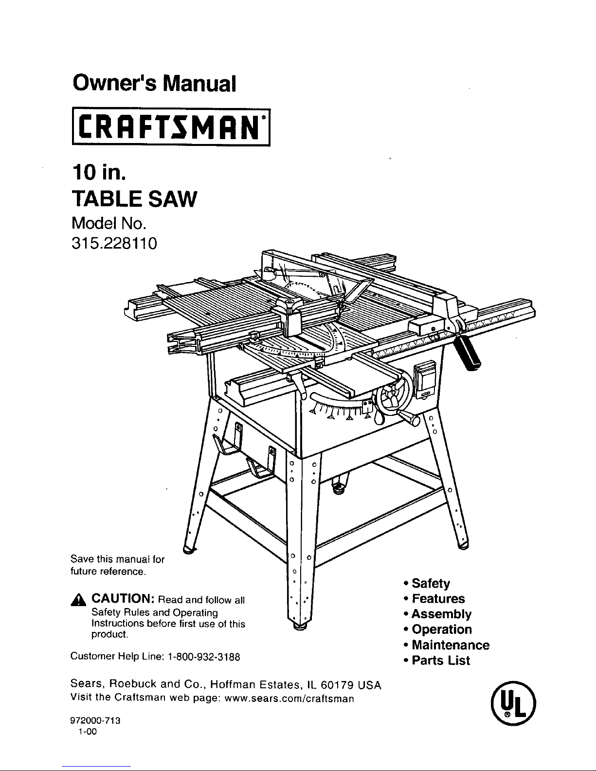
10 in.
TABLE SAW
Model No.
315.228110
Save this manual for
future reference.
_, CAUTION: Read and follow all
Safety Rules and Operating
Instructions before first use of this
product.
Customer Help Line: 1-800-932-3188
Sears, Roebuck and Co., Hoffman Estates, IL 60179 USA
visit the Craftsman web page: www.sears.com/craftsman
972000-713
1-00
• Safety
• Features
• Assembly
• Operation
• Maintenance
• Parts List
®
FULL ONE YEAR WARRANTY ON CRAFTSMAN TABLE SAW
If this rRRFTSMRN Table Saw fails due to a defect in material or workmanship within one year from the date of
purchase, Sears will repair it, free of charge
Contact a Sears Service Center for repair.
If this product is used for commercial or rental purposes, this warranty applies only for 90 days from the date of
purchase.
This warranty gives you specific legal rights, and you may also have other rights which vary from state to state.
Sears, Roebuck and Co., Dept. 817WA, Hoftman Estates, IL 60179
Your saw has many features for making cutting operations more pleasant and enjoyable. Safety, performance
and dependability have been given top priority in the design of this saw making it easy to maintain and operate.
CAUTION: Carefully read through this entire owner's manual before using your new saw. Pay close
attention to the Rules For Safe Operation, and all Safety Alert Symbols, including Danger, Warning and
Caution. If you use your saw properly and only for what it is intended, you will enjoy years of safe, reliable
service.
_. Look for this symbol to point out important safety precautions. It means attention!!! Your safety is involved.
,_ WARNING:
The operation of any power tool can resultinforeign objects being thrown into your eyes,
which can result in severe eye damage, Before beginning power tool operation, always
wear safety goggles or safety glasses with side shields and a full face shield when needed.
We recommend a Wide Vision Safety Mask for use over eyeglasses or standard safety
giasses with side shields, available at Sears Retail Stores.
• Warranty and Introduction .......................................................................................................................... 2
• Table Of Contents ..................................................................................................................................... 2-3
• Rules For Safe Operation ......................................................................................................................... 4-6
• Electrical ........................................................................................................................................................ 7
• Glossary and Product Specifications ........................................................................................................ 8
• Unpacking and Accessories ....................................................................................................................... 9
• Loose Parts List .................................................................................................................................... 10-11
• Tools Needed .............................................................................................................................................. 12
• Features .................................................................................................................................................. 13-15
• Assembly ................................................................................................................................................ 16-20
A. Assembly Of Leg Stand, Storage Brackets, and Mounting To Saw .................................................. 16-17
Assembling Leg Stand ............................................................................................................................ 16
Assembling Storage Brackets ................................................................................................................. 17
Mounting The Leg Stand On The Table Saw Base ................................................................................ 17
B. Assembly Of Rails, Tables, and Fences ............................................................................................ 18-19
To Install Front and Back Rail ................................................................................................................. 18
To Install Miter Table and Fence ............................................................................................................. 18
To Install Accessory Table and Rip Fence ............................................................................................. 19
(RRFTSMRN" TABLESAW315.228110 2
C.BladeCheckandBladeGuardAssembly..........................................................................................19-20
To Check Saw Blade Installation ............................................................................................................ 19
To Install Blade Guard ............................................................................................................................. 20
• Operation ................................................................................................................................................ 21-33
A. General Information ................................................................................................................................. 21
Grounding ................................................................................................................................................ 2t
Types Of Cuts ..................................................................................................................................... 21-22
Cutting Tips ............................................................................................................................................. 22
B. Settings and Adjustments ................................................................................................................... 23-28
To Remove The Blade ............................................................................................................................ 23
To Check Replace Or Adjust The Riving Knife and Blade Guard Assembly .......................................... 24
1. Remove The Throat Plate ............................................................................................................... 24
To Reduce The Risk Of Kickback ........................................................................................................... 25
To Avoid Kickback ................................................................................................................................... 25
To Make A Push Stick ............................................................................................................................. 26
Featherboard ........................................................................................................................................... 26
How To Make A Featherboard ................................................................................................................ 26
How To Mount A Featherboard ............................................................................................................... 26
To Adjust Blade Depth ............................................................................................................................ 27
To Adjust Blade Angle ............................................................................................................................. 27
To Set The Scale To The Blade .............................................................................................................. 27
To Lock Miter Table ................................................................................................................................. 28
C. Making Cuts ........................................................................................................................................ 28-33
To Make A Straight Cross Cut ............................................................................................................ 28-29
To Make A Miter Cut ............................................................................................................................... 29
To Make A Straight Rip Cut ..................................................................................................................... 29
To Make A Bevel Cross Cut .................................................................................................................... 30
To Make A Bevel Rip Cut ................................................................................................................... 30-31
To Make A Compound Miter Cut ............................................................................................................. 31
To Make A Large Panel Cut .................................................................................................................... 31
To Make Non-Through Cuts .................................................................................................................... 32
To Make Dado Cuts ................................................................................................................................ 33
• Maintenance ......................................................................................................................................... .. 34-36
A. General Maintenance .............................................................................................................................. 34
B. Specific Table Saw Maintenance ....................................................................................................... 34-36
To Set Blade At 0 Or 45 Degrees ........................................................................................................... 34
To Check The Alignment Of The Rip Fence To The Blade .................................................................... 35
To Adjust The Bevel Locking Lever ........................................................................................................ 35
To Align The Miter Locking Clamps ........................................................................................................ 36
To Adjust The Front and Rear Rail Clamps ............................................................................................ 36
To Adjust The Accessory Table .............................................................................................................. 36
• Sliding Miter Table Assembly .............................................................................................................. 37-41
Checking Sliding Miter Table Assembly ....................................................................................................... 38
To Check Miter Base Parallelism ............................................................................................................ 38
To Check Miter Fence Alignment ............................................................................................................ 39
Making Adjustments To Sliding Miter Table Assembly ........................................................................... 39-41
To Adjust The Miter Base ........................................................................................................................ 39
To Adjust The Miter Fence ...................................................................................................................... 40
To Adjust Quick Stop ............................................................................................................................... 41
• Lubrication .................................................................................................................................................. 42
Locker Bracket Assembly ............................................................................................................................. 42
Tilt / Elevating Mechanism ........................................................................................................................... 42
• Troubleshooting .................................................................................................................................... 44-45
• Exploded View and Repair Parts List .................................................................................................. 46-53
• Parts Ordering / Service ............................................................................................................... back page
3 CRAFTSMAN"TABLESAW315.228110
The purpose of safety symbols isto attract your attention to possible dangers. The safety symbols, and the
explanations with them, deserve your careful atten'iion and understanding. The safety warnings do not by
themselves eliminate any danger. The instructions or warnings they give are not substitutes for proper accident
prevention measures.
SYMBOL
A
A
A
A
Note:
MEANING
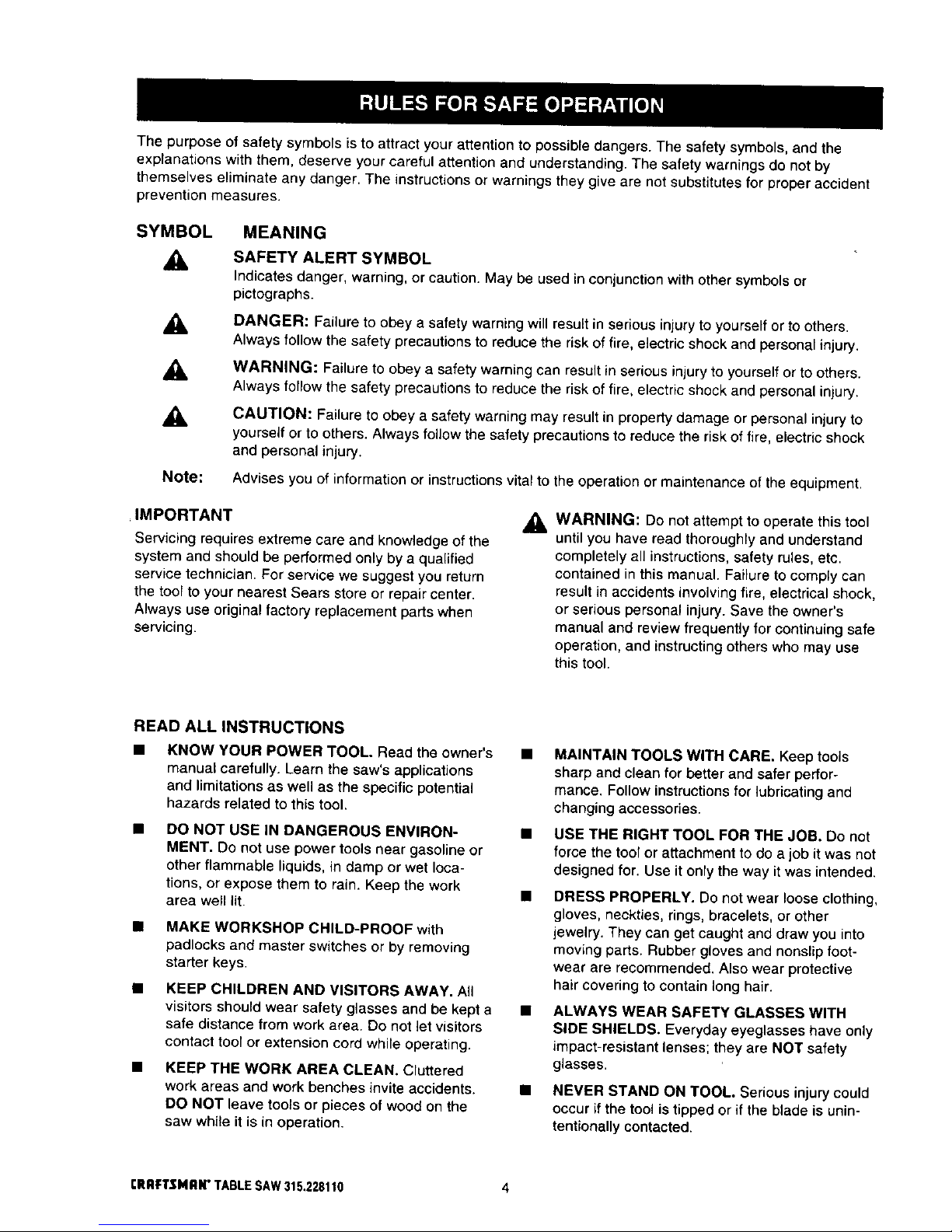
SAFETY ALERT SYMBOL
Indicatesdanger, warning, or caution, May be used in conjunctionwith other symbolsor
pictographs.
DANGER: Failure to obey a safety warning will result in serious injury to yourself orto others.
Always follow the safety precautions to reduce the risk of fire, electric shock and personal injury.
WARNING: Failure to obey a safety warning can result in serious injury to yourself or to others.
Always follow the safety precautions to reduce the risk of fire, electric shock and personal injury.
CAUTION: Failure to obey a safety warning may result in property damage or personal injury to
yourself or to others. Always follow the safety precautions to reduce the risk of fire, electric shock
and personal injury.
Advises you of information or instructions vital to the operation or maintenance of the equipment.
IMPORTANT
Servicing requires extreme care and knowledge of the
system and should be performed only by a qualified
service technician. For service we suggest you return
the tool to your nearest Sears store or repair center,
Always use original factory replacement parts when
servicing.
WARNING: Do not attempt to operate this tool
until you have read thoroughly and understand
completely all instructions, safety rules, etc.
contained in this manual. Failure to comply can
result in accidents involving fire, electrical shock,
or serious personal injury. Save the owner's
manual and review frequently for continuing safe
operation, and instructingothers who may use
this tool.
READ ALL INSTRUCTIONS
KNOW YOUR POWER TOOL. Read the owner's
manual carefully. Learn the saw's applications
and limitations as well as the specific potentia_
hazards related to this tool.
DO NOT USE IN DANGEROUS ENVIRON-
MENT. Do not use power tools near gasoline or
otherflammable liquids, in damp or wet loca-
tions, or expose them to rain. Keep the work
area well lit.
• MAKE WORKSHOP CHILD-PROOF with
padlocks and master switches or by removing
starter keys
• KEEP CHILDREN AND VISITORS AWAY. All
visitors should wear safety glasses and be kept a
safe distance from work area. Do not let visitors
contact tool or extension cord white operating.
• KEEP THE WORK AREA CLEAN. Cluttered
work areas and work benches invite accidents.
DO NOT leave tools or pieces of wood on the
saw while it is in operation,
• MAINTAIN TOOLS WITH CARE. Keep tools
sharp and clean for better and safer perfor-
mance. Follow instructions for lubricating and
changing accessories.
• USE THE RIGHT TOOL FOR THE JOB. Do not
force the tool or attachment todo a job itwas not
designed for. Use it only the way itwas intended.
• DRESS PROPERLY. Do not wear loose clothing,
gloves, neckties, rings, bracelets, or other
jewelry. They can get caughtand draw you into
movingparts. Rubber glovesand nonslipfoot-
wear are recommended. Also wear protective
haircovering to contain long hair.
• ALWAYS WEAR SAFETY GLASSES WITH
SIDE SHIELDS, Everyday eyeglasses have only
impact-resistant lenses; they are NOT safety
glasses.
• NEVER STAND ON TOOL. Serious injury could
occur if the tool is tipped or if the blade is unin-
tentionally contacted.
rRRFTSNRN* TABLESAW315.228110 4
RULES FOR SAFE OPERATION (Continued)
• DO NOT OVERREACH. Keep proper footing and
balance at all times.
SECURE WORK. Use clamps or a vise to hold
work when practical. It's safer than using your
hand and frees both hands to operate tool.
USE THE PROPER EXTENSION CORD. Make
sure your extension cord is in good condition.
Use only a cord heavy er_oughto carry the
current your productwill draw. An undersized
cord will cause a drop in linevoltage resultingin
lossof power and overheating.A wire gage size
(A.W.G.) ofat least 14 is recommended for an
extension cord 25 feet or less in length. If in
doubt, use the next heavier gage. The smaller
the gage number, the heavier the cord.
AVOID ACCIDENTAL STARTING. Be sure
switch is off when plugging in.
REMOVE WRENCHES AND ADJUSTING
KEYS. Get in the habit of checking - before
turningon tool- that hex keys and adjusting
wrenches are removed from tool.
CHECK DAMAGED PARTS. Before using the
tool again, check any damaged parts, including
guards,for properoperation and performance.
Check alignment of moving parts, binding of
moving parts,breakage of parts, saw stability,
mountingand any other conditionsthat may
affect itsoperation. A damaged part must be
properly repairedor replaced by a qualified
service technicianat a Sears store or repair
center to avoid riskof personal injury.
USE ONLY CORRECT BLADES. Use the right
blade size, style and cutting speed for the
material and the type of cut. Bladeteeth should
point downtoward the front of the table.
USE RECOMMENDED ACCESSORIES. Using
improper accessories may riskinjury.
USE ONLY SEARS REPLACEMENT PARTS.
All repairs, whether electrical or mechanical,
shouldbe made by a qualified service technician
at a Sears store or repaircenter.
KEEP GUARDS IN PLACE and in good working
order. This includes the blade guard, riving knife,
and anti-kickback pawls.
CHECK DIRECTION OF FEED. Feed work into
a blade or cutter against the direction of rotation
of the blade or cutter only.
DISCONNECT ALL TOOLS. When not in use,
before servicing, or when changing attachments,
blades, bits, cutters, etc., all tools should be
disconnected from power supply.
• DO NOT FORCE THE TOOL. It will do the job
better and more safely at the rate for which it
was designed.
• NEVER LEAVE TOOL RUNNING UNAT-
TENDED. TURN THE POWER OFF. Do not
leave tool until it comes to a complete stop.
• BEFORE DISCONNECTING THE MOTOR;
unplug the saw from power supply.
WARNING: When servicing, use only identical
Craftsman replacement parts. Use of any other
parts may create a hazard or cause product
damage.
NEVER USE THIS TOOL IN AN EXPLOSIVE
ATMOSPHERE. Normal sparking of the motor
could ignite fumes.
MAKE SURE THE WORK AREA HAS AMPLE
LIGHTING to see the work and that no obstruc-
tions will interfere with safe operation BEFORE
performing any work using this tool.
DO NOT USE TOOL IF SWITCH DOES NOT
TURN IT ON AND OFF. Have defective switches
replaced by a qualified service technician at a
Sears store or repair center
GUARD AGAINST ELECTRICAL SHOCK by
preventing body contact with grounded surfaces
such as pipes, radiators,ranges, refrigerator
enclosures.
• GROUND ALL TOOLS. See Electrical page.
• WEAR A DUST MASK to keep from inhaling fine
particles.
• PROTECT YOUR HEARING. Wear hearing
protection during extended periods of operation.
• DO NOT OPERATE THIS TOOL WHILE UN-
DER THE INFLUENCE OF DRUGS, ALCOHOL,
OR ANY MEDICATION.
STAY ALERT AND EXERCISE CONTROL.
Watch what you are doing and use common
sense. Do not operate tool when you are tired.
Do not rush.
• AVOID AWKWARD OPERATIONS AND HAND
POSITIONS where a sudden slip could cause
your hand to move into the blade. ALWAYS
make sure you have good balance.
• ALWAYS SUPPORT LARGE WORK PIECES
while cutting to minimize risk of blade pinching
and kickback. Saw may slip, walk or slide while
cutting large or heavy boards,
5 CRRFTSMaW TABLESAW315.228110
RULES FOR SAFE OPERATION (Continued)
GUARD AGAINST KICKBACK. Kickback can
occur when the blade stalls, drivingthe work
piece back toward the operator. It can pull your
hand into the blade, resultingin serious personal
injury. Stay out ofthe blade path and turn switch
off immediately if blade bindsor stalls.
USE A SUPPORT FOR THE SIDES AND BACK
.OF THE SAW TABLE when sawingwide or long
workpieces. Use a sturdy"outrigger" support if a
table extension is more than 24 inches longand
is attached to the saw, to prevent tipping.
CUT ONLY WOOD, PLASTIC OR WOOD-LIKE
MATERIALS. Do notcut metal.
• NEVER cut more than one piece at a time. DO
NOT STACK more than one workpiece on the
saw table at a time.
DO NOT REMOVE THE SAW'S BLADE
GUARDS. Never operate the saw with any guard
or cover removed. Make sure all guards are
operating properly before each use.
NEVER PERFORM ANY OPERATION FREE-
HAND. Always place the workpieceto be cut on
the saw table and positionit firmlyagainst the
fence as a backstop.
USE THE RIP FENCE. Always use a fence or
straight edge guide when ripping.
BEFORE MAKING A CUT, be sure all adjust-
merits are secure.
• BE SURE THE BLADE PATH IS FREE OF
NAILS. Inspect for and remove all nailsfrom
lumber before cutting. •
• BE SURE THE BLADE CLEARS THE
WORKPIECE. Never start the saw with the blade
touchingthe workpiece.
• KEEP HANDS AWAY FROM cu'rrlNG AREA.
Do not reach underneath work or in blade cutting •
path with your hands and fingers for any reason.
Always turn the power off.
• USE A PUSH BLOCK OR PUSH STICK for
workpieces so small that your fingers go under
the blade guard. NEVER TOUCH BLADE or
other moving parts during use, for any reason.
,_ WARNING: Blade coasts after being turned off.
ALLOW THE MOTOR TO COME UP TO FULL
SPEED before startinga cut to avoid blade
binding or stalling.
ALWAYS PUSH THE WORKPIECE; never pull it
toward the saw.
DO NOT FEED THE MATERIAL TOO QUICKLY.
Do not force the workpiece againstthe blade.
ALWAYS TURN OFF SAW before disconnecting
it, to avoid accidental starting when reconnecting
to power supply. NEVER leave the table saw
unattended while connected to a power source.
BEFORE CHANGING THE SETUP, REMOVING
COVERS, GUARDS, OR BLADE; unplug the
saw from power supply.
KEEP TOOL DRY, CLEAN, AND FREE FROM
OIL AND GREASE. Always use a clean cloth
when cleaning. Never use brake fluids, gasoline,
petroleum-based products,or any solventsto
clean tool.
KEEP BLADES CLEAN, SHARP AND WITH
SUFFICIENT SET. Sharp blades minimize
stalling and kickback.
USE ONLY OUTDOOR EXTENSION CORDS.
Use only extension cords withthe marking
"Acceptable for use with outdoorappliances;
store cordsindoorswhile not in use." Use
extension cordswith an electrical rating not less
than the saw's rating. Always disconnectthe
extension cordfrom the outletbefore disconnect-
ing the productfrom the extension cord.
INSPECT TOOL CORDS AND EXTENSION
CORDS PERIODICALLY and, ifdamaged, have
repaired by a qualifiedservice technicianat a
Sears store or repair center. Stay constantly
aware of cord location and keep itwell away
from the moving blade.
DO NOT ABUSE CORD. Never yank cord to
disconnect itfrom receptacle. Keep cord from
heat, oil, and sharp edges.
SAVE THESE INSTRUCTIONS. Refer tothem
frequently and use to instructother users. If you
loan someone thistool, loanthem these instruc-
tions also.
SAVE THESE INSTRUCTIONS
[RAFTSMAN" TABLESAW315.228110 6
EXTENSION CORDS
Use only 3-wire extension cords that have 3-prong
grounding plugs and 3-pole receptacles that accept
the tool's plug. When using a power tool at a consid-
erable distance from the power source, use an
extension cord heavy enough to carry the current that
the tool will draw. An undersized extension cord will
cause a drop in line voltage, resulting in a loss of
power and causing the motor to overheat. Use the
chart provided below to determine the minimum wire
size required in an extension cord. Only round jack-
eted cords _isted by Underwdter's Laboratories (UL_
should be used.
Length of Extension Cord Wire Size (A.W.G.)
Up to 25 feet 14
26-100 feet 12
When working with the tool outdoors, use an exten-
sion cord that is designed for outside use. This is
indicated by the letters WA on the cord's jacket.
Before using an extension cord, inspect it for loose or
exposed wires and cut or worn insulation.
_k CAUTION: Keep the cord away from the cutting
area and position the cord so that it will not be
caught on lumber, tools, or other objects during
cutting operations.
ELECTRICAL CONNECTION
Your Sears Craftsman Table Saw is powered by a
precision built electric motor. It should be connected
to a power supply that is 120 volts, 60 Hz, AC only
(normal household current). Do not operate this tool
on direct current (DC). A substantial voltage drop will
cause a loss of power and the motor will overheat. If
the saw does not operate when plugged into an
out_et,double check the power supply.
SPEED AND WIRING
The no-load speed of your table saw is approximately
4,800 rpm. This speed is not constant and decreases
under a load or with lower voltage. For voltage, the
wiring in a shop is as important as the motor's horse-
power rating. A line intended only for lights cannot
properly carry a power tool motor. Wire that is heavy
enough for a short distance will be too light for a
greater dist.ance. A line that can support one power
tool may not be able to support two or three tools.
GROUNDING INSTRUCTIONS
In the event of a malfunction or breakdown, grounding
provides a path of least resistance for electric current
to reduce the risk of electric shock. This tool is
equipped with an electric cord having an equipment-
grounding conductor and a grounding plug. The plug
must be plugged into a matching outlet that is properly
installed and grounded in accordance with all local
codes and ordinances.
Do not modify the plug provided. If it will not fit the
outlet, have the proper outlet installed by a qualified
electrician, improper connection of the equipment-
grounding conductor can result in a risk of electric
shock. The conductor with insulation having an outer
sudace that is green with or without yellow stripes is
the equipment-grounding conductor, if repair or
replacement of the electric cord or plug is necessary,
do not connect the equipment-grounding conductor to
a live terminal.
Check with a qualified electrician or service personnel
if the grounding instructions are not completely
understood, or if in doubt as to whether the tool is
properly grounded.
Repair or replace a damaged or worn cord immedi-
ately.
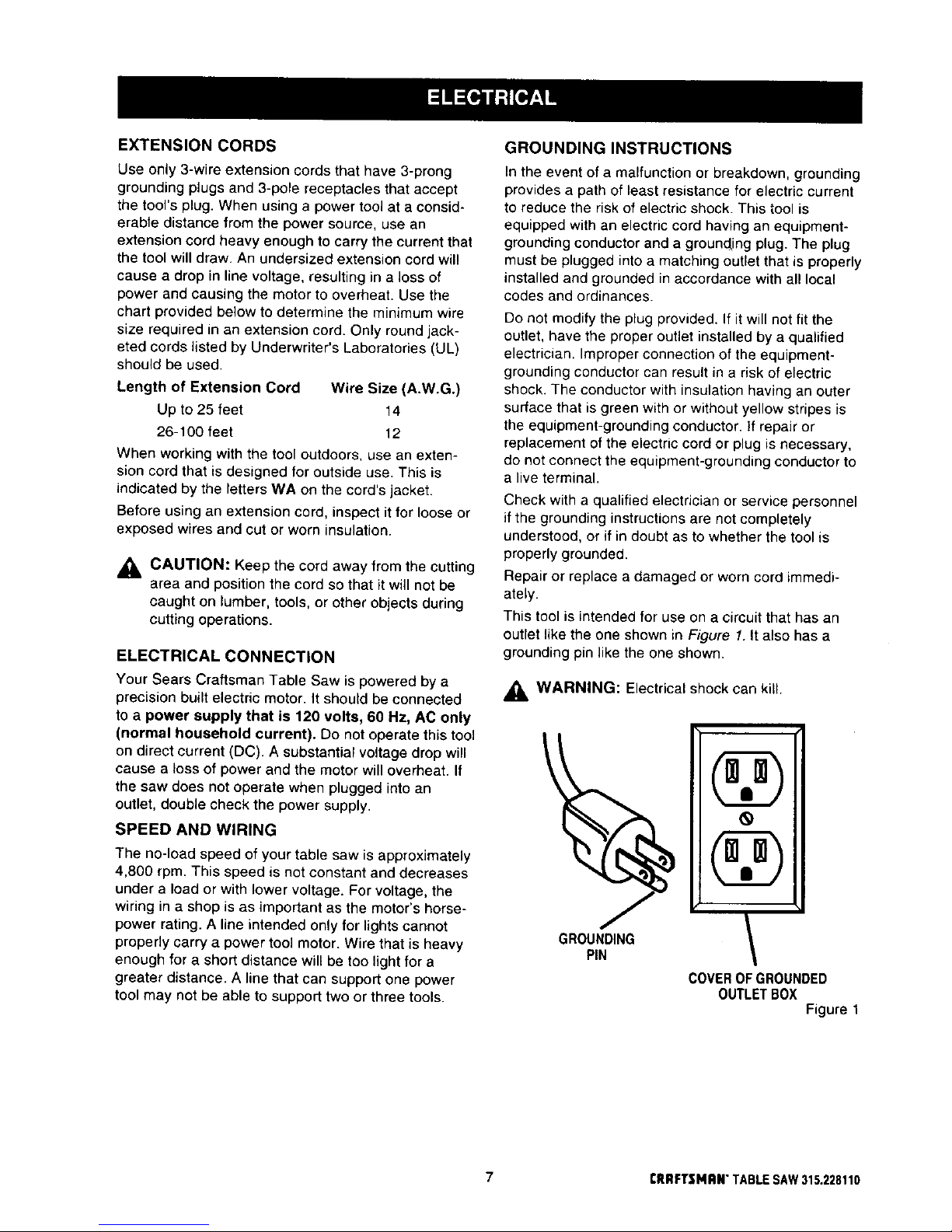
This tool is intended for use on a circuit that has an
outlet like the one shown in Figure I. tt also has a
grounding pin like the one shown.
_, WARNING: Electrical shock can kill.
@
GROUNDING
PIN
\
DOVER OF GROUNDED
OUTLET BOX
Figure 1
7 I"RRFTSMRN" TABLE SAW 315.228110

Anti-Kickback Pawls
Toothed safety devices behind the blade designed to
stop a workpiece from being kicked back at the
operator during a rippingoperation.
Arbor
The shaft on which a blade or cuttingtool is mounted.
Bevel Cut
A cutting operation made withthe blade at any angle
other than 90" to the saw table.
Compound Cut
A cut with both a miter angle and a bevel angle.
Crosscut
A cuttingoperation made across the grain or the width
of the workpiece.
Dado
A non-throughcut that gives a square notch or trough;
requiresa special blade.
Featherboard
A device to helpguide workpieces duringrip cuts.
Freehand (for talole saw)
Dangerous practice of making a cut withoutusing rip
or miter fences. See Safety Rules.
Gum
A sticky, sap-based residue from wood products.
Heel
Alignment of the blade.
Kerr
The material removed by the blade in a throughcutor
the slot produced by the blade in a non-throughcut.
Kickback
A hazard that can occur when blade binds or stalls,
throwingworkpiece back toward operator.
Leading End
The end of the workpiece pushed intothe cuttingtool
first.
Miter Cut
A cutting operation made with the miter gage using
any angle other than 0°on the miter gage.
Molding
A non-through cut that gives a varied shape to the
workpiece and requires a special blade.
Push Stick
A device used to feed the workpiece through the saw to
help keep the operator's hands well away from the blade.
Push Block
A device used for non-through cut type operations to
help keep the operator's hands away from the blade.
Rabbet
A notch in the edge of a workpiece.
Resaw
A cutting operation to reduce the thickness of the
workpiece in order to make thinner pieces.
Resin
A sticky, sap-based substance.
Rip Cut
A cut made with the grain of the workpiece.
Saw Blade Path
The area directly in line withthe blade -- over, under,
behind, or in front of it. Also, the workpiecearea
whichwill be or has been cut by the blade.
Set
The distance that the tip of the saw blade tooth is bent
(or set) outward from the face of the blade.
Throw-Back
Saw throwing back a workpiece; similar to kickback.
Through Sawing
Any cutting operationwhere the blade extends
completelythroughthe workpiece.
Trailing End
The workpiece end last cut by the blade in a rip cut.
Workpiece
The itemon which the cutting operation is being done.
The surfacesof a workpiece are commonly referred to
as faces, ends, and edges.
Worktable
The surface on which the workpiece rests while
performinga cuttingoperation.
Blade Arbor 5/8 in,
Blade Diameter 10 in.
Blade Tilt 0° - 45°
Net Weight Without Leg Stand 75 Ibs,
Net Weight With Leg Stand 97 Ibs,
Rating 120 V, 60 Hz - AC only
Input 15 Amperes
No Load Speed 4,800 RPM
Cutting Capacity with Miter at 0"/Bevel 0°: 3-9/16 in.
Cutting Capacity with Miter at 0VBevel 45°: 2-t/2 in.
CRRFTSNAN"TABLESAW315.228110 8
Your new table saw has been designed to give you
many years of high quality performance. To insure
this goal, proper care and treatment is important.
Careful treatment begins with removing all parts from
the canon and checking them against the list of loose
pans.
Your table saw is shipped complete in one carton and
includes a leg stand, two table extensions, a rip fence,
a miter fence with adjusting clamp, a blade guard, rails
and hardware.
• Separate the saw and all parts from the packing
materials and check each against the packing list,
especially the small parts that can be hidden in the
packing material.
Note: Do not discard the packing materials until you
have carefully inspected the saw, identifiedall
parts, and satisfactorily operated your new saw.
If you are missing a part, check the packaging before
contacting Sears.
If any parts are missing, do not attempt to assemble
your table saw, plug in the power cord, or turn the switch
on until the missing parts are obtained and are installed
correctly. Complete parts lists are lecated at the end of
this manual. Use these lists to identify the part number
of any missing part. Contact your Sears Service Center
or Retail store and get the missing part(s) before
assembling and trying to use your saw.
A
WARNING: Never use gasoline, naptha, or
other highly volatile solvents. Do not ever let
brake fluids, gasoline, petroleum-based
products, or penetrating oils contact plastic pans.
Such chemicals can weaken or destroy plastic.
A
WARNING: To prevent accidental starting that
could cause possible serious personal injury,
assemble all parts to your saw before connecting
it to power supply. Saw should never be
connected to power supply when you are
assembling parts, making adjustments, installing
or removing blades, or when not in use.
_1, WARNING: If any parts are missing, do not
operate this tool until the missing parts are
replaced. Failure to do so could result in possible
serious personal injury.
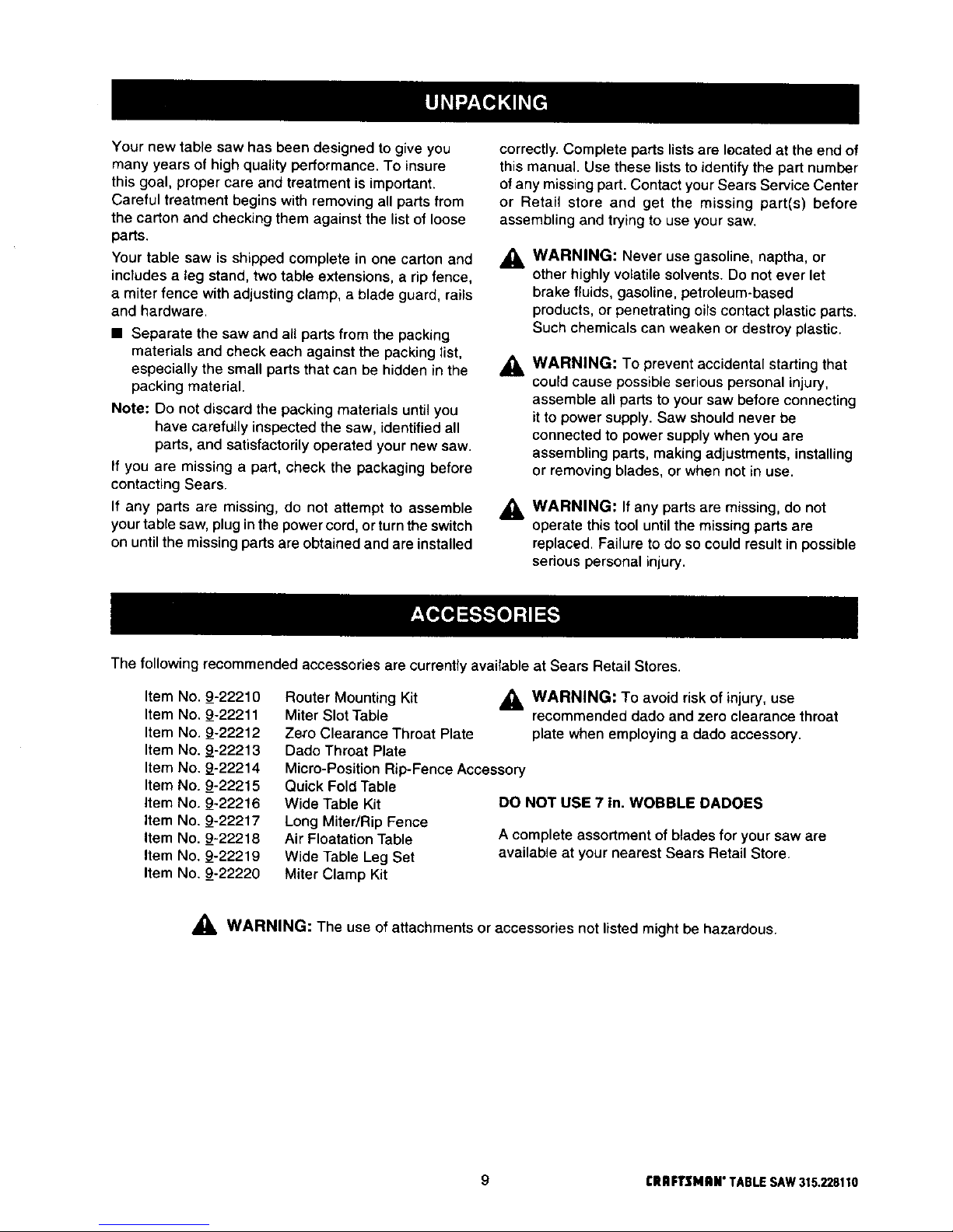
The following recommended accessories are currently available at Sears Retail Stores.
Item No. 9-22210
Item No. 9-22211
Item No. 9-22212
Item No. 9-22213
Item No. 9-22214
Item No. 9_-22215
Item No. 9-22216
Item No. 9-22217
Item No. 9-22218
Item No. 9-22219
Item No. 9_-22220
Router Mounting Kit _1, WARNING: To avoid risk of injury, use
Miter Slot Table recommended dado and zero clearance throat
Ze_'oClearance Throat Plate plate when employing a dado accessory.
Dado Throat Plate
Micro-Position Rip-Fence Accessory
Quick Fold Table
Wide Table Kit
Long Miter/Rip Fence
Air Floatation Table
Wide Table Leg Set
Miter Clamp Kit
DO NOT USE 7 in. WOBBLE DADOES
A complete assortment of blades for your saw are
available at your nearest Sears Retail Store.
,_, WARNING: The use of attachments or accessories not listed might be hazardous.
9 rRRFTSMIIN" TABLESAW315.228110
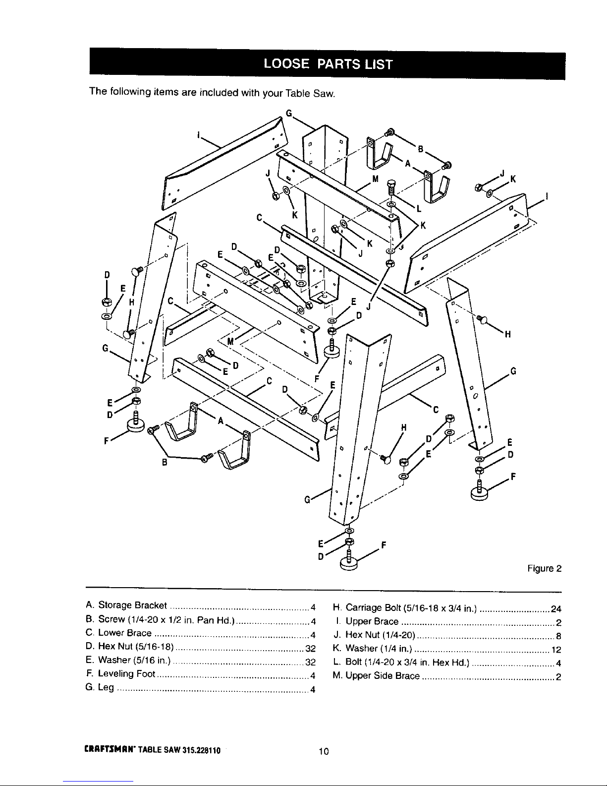
The following items are included with your Table Saw.
D
D
H
E
Figure 2
A. Storage Bracket ..................................................... 4
B. Screw (1/4-20 x 1/2 in. Pan Hd.) ............................ 4
C. Lower Brace ........................................................... 4
D. Hex Nut (5/16-18) ................................................. 32
E. Washer (5/16 in.} .................................................. 32
E Leveling Foot .......................................................... 4
G, Leg ......................................................................... 4
H. Carriage Bolt (5/16-18 x 3/4 in.) ........................... 24
I. Upper Brace ........................................................... 2
J. Hex Nut (1/4-20) ..................................................... 8
K. Washer (1/4 in.) .................................................... 12
L. Bolt/1/4-20 x 3/4 in. Hex Hd.) ................................ 4
M. Upper Side Brace ................................................... 2
rRAFTSMIIN" TABLESAW315.228110 10
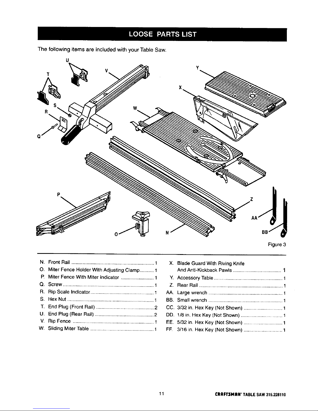
The following items are included with your Table Saw.
T
R
Q
U
Y
N
Z
AA/
BB/
Figure 3
N. Front Rail ............................................................ 1
O. Miter Fence Holder With Adjusting Clamp .......... 1
P. Miter Fence With Miter Indicator ........................ 1
Q. Screw .................................................................. 1
R. Rip Scale Indicator .............................................. 1
S. Hex Nut ............................................................... 1
T. End Plug (Front Rail) .......................................... 2
U. End Plug (Rear Rail) ........................................... 2
V. Rip Fence ........................................................... 1
W. Sliding Miter Table .............................................. 1
X. Blade Guard With Riving Knife
And Anti-Kickback Pawls ................................... 1
Y. Accessory Table .................................................. 1
Z. Rear Rail ............................................................. 1
AA. Large wrench ...................................................... 1
BB. Small wrench ...................................................... 1
CC. 3/32 in. Hex Key (Not Shown) ............................ 1
DD. 1/8 in. Hex Key (Not Shown) .............................. 1
EE, 5/32 in. Hex Key (Not Shown) ............................ 1
FIE 3/16 in. Hex Key (Not Shown) ............................ 1
11 CRRFTSMRN"TABLESAW315.228110
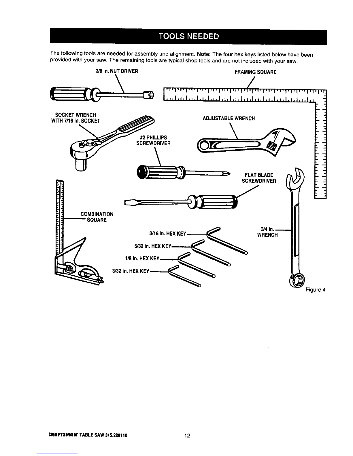
The following tools are needed for assembly and alignment. Note: The four hex keys listed below have been
provided with your saw. The remaining tools are typical shop tools and are not included with your saw.
3/8 in. NUT DRIVER
SOCKETWRENCH
WITH7/16in.SOCKET
COMBINATION
SQUARE
FRAMING SQUARE
'U'l'O'l'l'l'l'l,U,l,l,l,l,t, ,_rl,g,f,v,l,l,l,l,l,l,l,U,l,f.
.t.l,',l,*.l.,.l,L,J.l,l.,.I,*,l.*,l,,,I.,,I,_.l.,,I.i
ADJUSTABLEWRENCH
#2 PHILLIPS
SCREWDRIVER
FLATBLADE I _
SCREWDRIVER
3/'16in.HEXKEY,---,_-,_,_
5/32in. HEXKEY._.._-_._._
1/8in. HEXKEY._--__
3/32in,HEXKEY_
3/4in.
WRENCH
_ Figure
CRRFTSMRN"TABLESAW315.228110 12
Your saw is designed to perform as a versatile,
accurate, precision cutting tool that is easy to operate.
It is equipped with the following features for safety,
ease of use, and high-quality performance:
• a carbide tipped combination blade
• a bevel indicator to set the exact angle of the blade,
with locking lever
• an adjustable and reversible sliding miter table
• an adjustable miter fence with miter indicator
• an adjustable accessory table
• an adjustable rip fence with scale indicator
• an adjustable riving knife (splitter) and blade guard
with anti-kickback pawls
• front and rear guide rails with an easy-to-read scale
on front rail
• a dust exhaust (2-1/2 in. hole) that can be adapted
to a standard shop vacuum if desired
• blade adjusting handle to set depth of cut
• switch with Iockable cover plate to help prevent
unauthorized use
• aleg stand
These features provide ease of cutting with all types of
wood.
_, WARNING: Before attempting to use your saw,
familiarize yourself with all operating features
and safety requirements.
OPERATING COMPONENTS
The upper portion of the blade projects up through the
table, surrounded by an insert called the throat plate.
To cut wood at a bevel, the blade must be tilted, using
the blade adjustment handTe,scale, and bevel indica-
tor found on the front of the cabinet. Inside the
cabinet, adjustable positive stops control the degree
of movement.
The sliding miter table assembly is used for all cross-
cutting operations. The miter fence is easily adjusted
to cut wood at an angle by loosening the adjusting
clamp, setting the fence to the miter scale, and
retightening the clamp. The sliding miter table, which
rests on a base mounted on the rails, can be reposi-
tioned along the rails for wide work. It can be reversed
for ripping so the projecting base is in the back.
Your saw includes a rip fence and an accessory table.
The accessory table can be moved from the right side
of the saw to the left side as needed. The rip fence is
used to position work that will be cut lengthwise. A
scale on the front rail shows the distance between the
rip fence and the blade.
_lL CAUTION: The saw blade "coasts" after the
saw is turned off.
SPEED AND WIRING
The no-load speed of your table saw is approximately
4,800 rpm. The speed will not remain constant but will
be less under a load. The wiring in a shop is as
important as the motor's horsepower rating. A line
intended for lights only will not properly carry a
power tool motor. Wire that is heavy enough for a
short distance will be too light for a greater distance. A
line that can support one power tool may not be able
to support two or three tools.
_i, WARNING: To prevent possible electrical
hazards, have a qualified electrician check the
line if you are not certain that it is properly wired.
_i, WARNING: Observe all normal safety
precautions related to avoiding electrical shock.
SAFETY DEVICES
Safety devices on your saw include the blade guard,
the anti-kickback pawls, and the riving knife (also
known as a splitter or spreader). The blade guard =sa
clear strong plastic shield designed to prevent acci-
dental contact with the blade. It also deflects any
flying debris from within.
_, WARNING: Although many of the illustrations in
this manualare shownwith the blade guard
removed for clarity,do notoperate the saw
withoutthe blade guard unless specifically
instructedto do so.
The riving knife is a metal device directly behind and
above the blade. It is used to help keep the cut wood
from binding together and causing possible kickback. It
is very important to use the riving knife for all through-
sawing operations. The anti-kickback pawls are
toothed plates mounted on the riving knife. Their teeth
point away from the work in case the work should be
pulled back, toward the operator. Then the teeth dig
into the wood to help prevent or reduce the possibility
of kickback.
Your saw features a receptacle on the right side of the
cabinet that permits use of accessories. Use only
accessories that are listed for use with this tool. When
using a listed accessory, unplug the saw motor cord
and use the receptacle and the saws main power
switch to operate the accessory.
13 CRRFTSMRN"TABLESAW315.228110
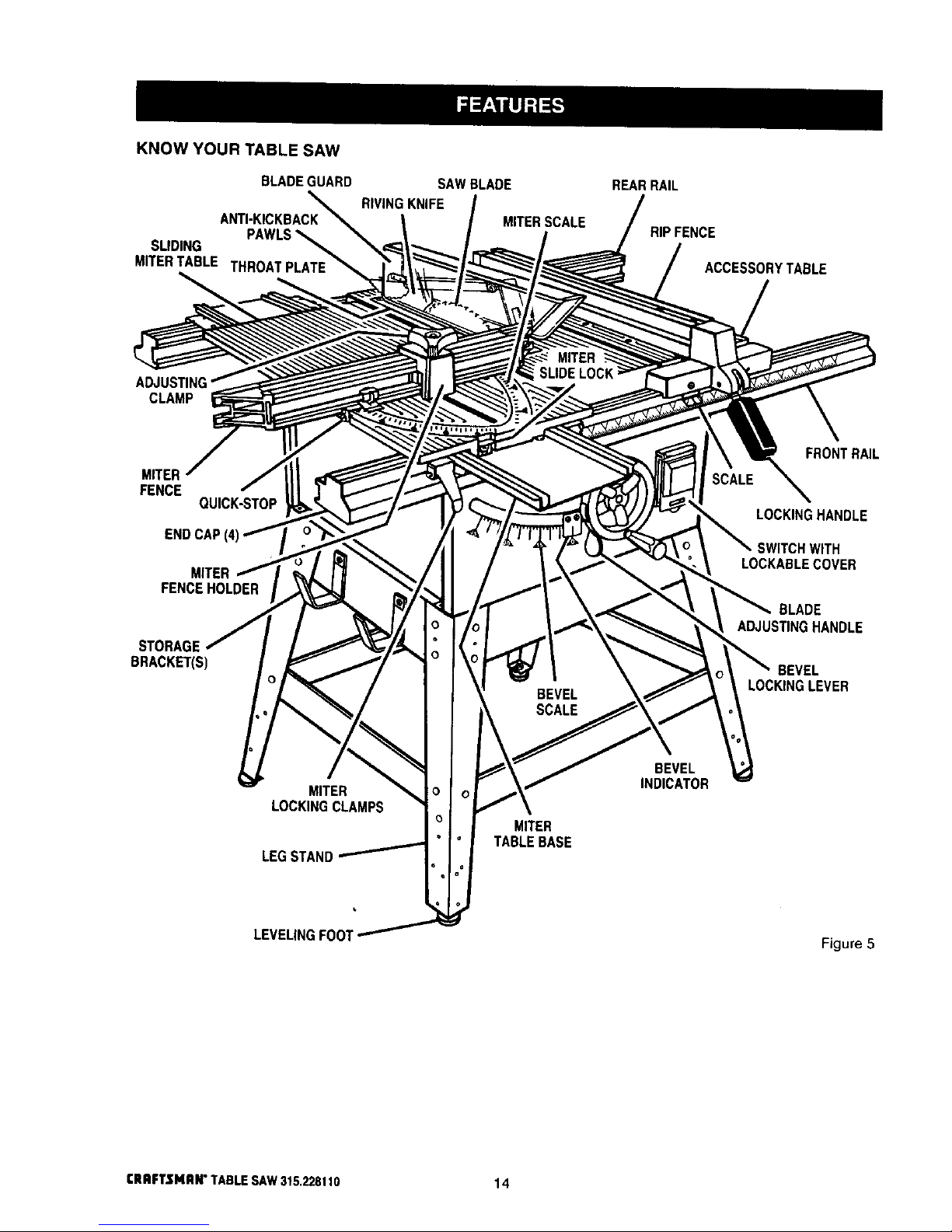
KNOW YOUR TABLE SAW
BLADEGUARD
SLIDING PAWLS_
MITERTABLE THROATPLATE
SAW BLADE
RIVING KNIFE
MITER SCALE
REARRAIL
RIP FENCE
ACCESSORYTABLE
ADJUST
CLAMP
MITER
FENCE
QUICK-STOP
END CAP
MITER
FENCEHOLDER
STORAGE
BRACKETS)
LOCKINGCLAMPS
LEGSTAND
MITER
TABLE BASE
BEVEL
INDICATOR
FRONTRAIL
HANDLE
NITH
LOCKABLECOVER
BLADE
ADJUSTINGHANDLE
BEVEL
LOCKINGLEVER
LEVELINGFOOl
Figure5
CRAFTSMAN"TABLESAW315,228110 14
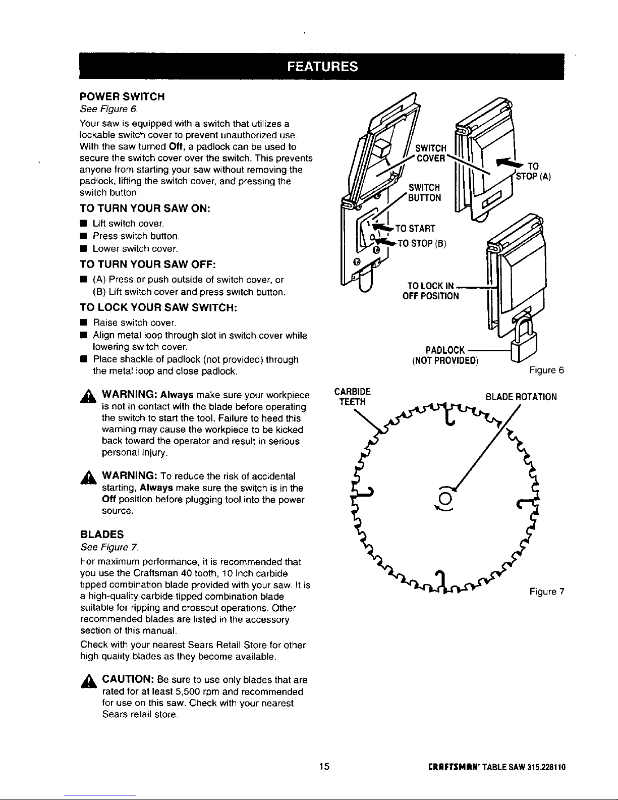
POWER SWITCH
See Figure 6.
Your saw is equipped with a switch that utilizes a
Iockable switch cover to prevent unauthorized use.
With the saw turned Off, a padlock can be used to
secure the switch cover over the switch. This prevents
anyone from starting your saw without removing the
padlock, lifting the switch cover, and pressing the
switch button.
TO TURN YOUR SAW ON:
• Lift switch cover.
• Press switch button.
• Lower switch cover.
TO TURN YOUR SAW OFF:
• (A) Press or push outside of switch cover, or
(B) Lift switch cover and press switch button.
TO LOCK YOUR SAW SWITCH:
• Raise switch cover.
• Align metal loop through slot in switch cover while
lowering switch cover.
• Place shackle of padlock (not provided) through
the metal loop and close padlock.
_1= W ARNING: Always make sure your workpiece
=snot in contact with the blade before operating
the switch to start the tool. Failure to heed this
warning may cause the workpiece to be kicked
back toward the operator and result in serious
personal injury.
,_ WARNING: To reduce the risk ofaccidental
starting, Always make sure the switch is in the
Off position before pluggingtool intothe power
source.
BLADES
See Figure 7.
For maximum performance, it is recommended that
you use the Craftsman 40 tooth, 10 inch carbide
tipped combination blade provided with your saw. It is
a high-quality carbide tipped combination blade
suitable for ripping and crosscut operations. Other
recommended blades are listed in the accessory
section of this manual.
Check with your nearest Sears Retail Store for other
high quality blades as they become available.
_k CAUTION: Be sure to use only blades that are
rated for at least 5,500 rpm and recommended
for use on this saw. Check with your nearest
Sears retail store.
CARBIDE
TEETH
SWITCH
SWITCH
_TO START
I
(B)
TO LOCK IN
OFF POSITION
PADLOCK
(NOTPROVIDED)
TO
Figure 6
BLADE ROTATION
Figure 7
15 CRRFTSMRN"TABLESAW315.228110
Assembly is best done in the area where the saw will be used. When you remove the table saw base, loose
parts, and hardware from the packing materials, check all items with the loose parts list and drawing. If you are
unsure about the description of any part, refer to the drawing. If any parts are missing, delay assembling until
you have obtained the missing part(s).
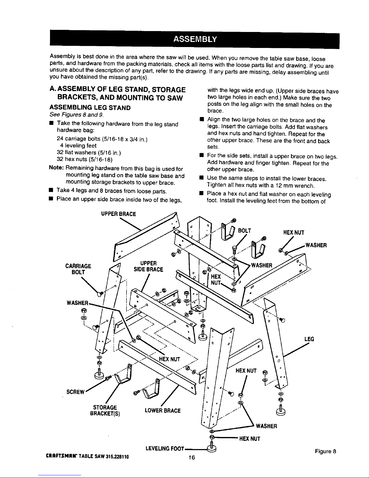
A. ASSEMBLY OF LEG STAND, STORAGE
BRACKETS, AND MOUNTING TO SAW
ASSEMBLING LEG STAND
See Figures 8 and 9
• Take the fottowing hardware from theteg stand
hardware bag:
24 carriage bolts (5/16-18 x 3/4 in)
4 leveling feet
32 fiat washers (5/16 in)
32 hex nuts (5/16-18)
Note: Remaining hardware from this bag is usedfor
mounting leg stand on the table saw base and
mounting storage brackets to upper brace.
• Take 4 legs and 8 braces from loose parts.
• Place an upper side brace inside two of the legs,
with the legs wide end up. (Upper side braces have
two large holes in each end.) Make sure the two
posts on the leg align with the small holes on the
brace.
Align the two large holes on the brace and the
legs. Insertthe carriage bolts. Add flat washers
and hex nuts and hand tighten. Repeat for the
other upper brace. These are the front and back
sets.
• For the side sets, install a upper brace on two legs.
Add hardware and finger tighten. Repeat for the
other upper brace.
• Use the same steps to install the lower braces.
Tighten all hex nuts with a 12 mm wrench.
• Place a hex nut and flat washer on each leveling
foot. Install the leveling feet from the bottom of
UPPERBRACE
BOLT HEXNUT
CARRIAGE
BOLT
I
L
LEG
STORAGE LOWERBRACE
BRACKET(S)
LEVELINGFOOT--_'_ HEX
16
WASHER
NUT
Figure 8
CRAFTSMAN"TABLESAW315.228110
each leg with the bolts pointing up. Cap with the
remaining fiat washers and hex nuts but do not
tighten.
• Move the leg set to desired location. Adjust the
leveling feet with a 12 mm wrench, then tighten the
top hex nut.
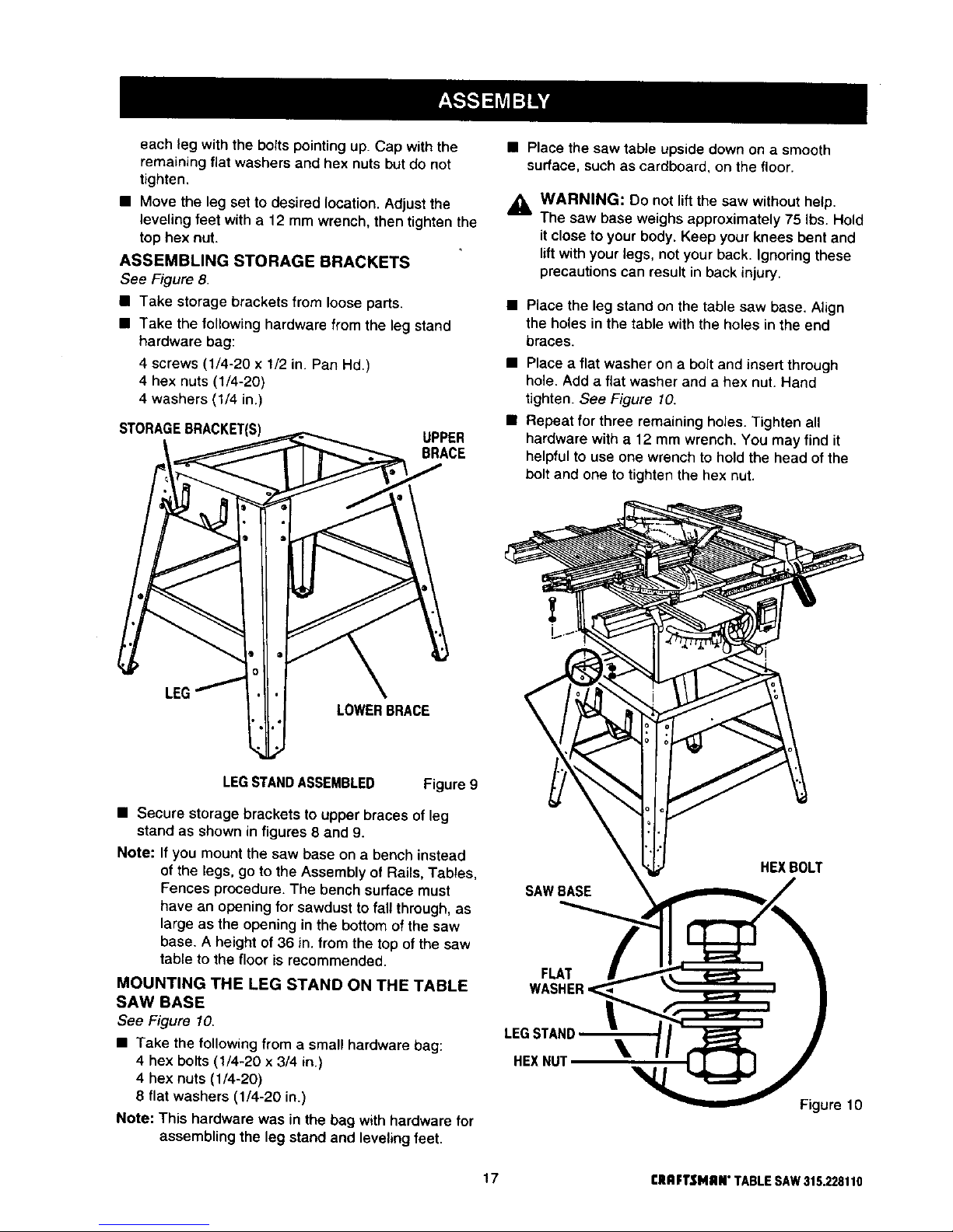
ASSEMBLING STORAGE BRACKETS
See Figure 8,
• Take storage brackets from loosepads.
• Take the followinghardware fromthe leg stand
hardware bag:
4 screws (1/4-20 x 1/2 in. Pan Hd.)
4 hex nuts (1/4-20)
4 washers (1/4 in.)
STORAGEBRACKET(S)
UPPER
BRACE
• Place the saw tabte upside down on a smooth
surface, such as cardboard, on the floor.
_i, WARNING: Do not lift the saw without help.
The saw base weighs approximately 75 Ibs. Hold
it close to your body. Keep your knees bent and
lift with your legs, not your back. Ignoring these
precautions can result in back injury.
• Place the leg stand on the table saw base. Align
the holes in the table with the holes in the end
braces.
• Place a flat washer on a bolt and insert through
hole. Add a flat washer and a hex nut. Hand
tighten. See Figure 10.
• Repeat for three remaining hotes. Tighten aU
hardware with a 12 mm wrench. You may find it
helpful to use one wrench to hold the head of the
bolt and one to tighten the hex nut.
$
LOWERBRACE
LEGSTANDASSEMBLED Figure 9
• Secure storage brackets to upper braces of leg
stand as shown in figures 8 and 9.
Note: If you mount the saw base on a bench instead
of the legs, go to the Assembly of Rails, Tables,
Fences procedure. The bench surface must
have an opening for sawdust to fall through, as
large as the opening in the bottom of the saw
base. A height ot 36 in. from the top of the saw
table to the floor is recommended.
MOUNTING THE LEG STAND ON THE TABLE
SAW BASE
See Figure 10.
• Take the followingfrom a smaUhardware bag:
4 hex bolts (1/4-20 x 3/4 in.)
4 hex nuts (1/4-20)
8 flat washers {114-20 in.)
Note: This hardware was in the bag with hardware for
assembling the leg stand and leveling feet.
SAW BASE
FLAT
LEGSTAND
\
HEXNUT
HEXBOLT
Figure 10
17 CRAFTSMAN"TABLESAW315.228110
 Loading...