

Page 1
OPERATOR’S MANUAL
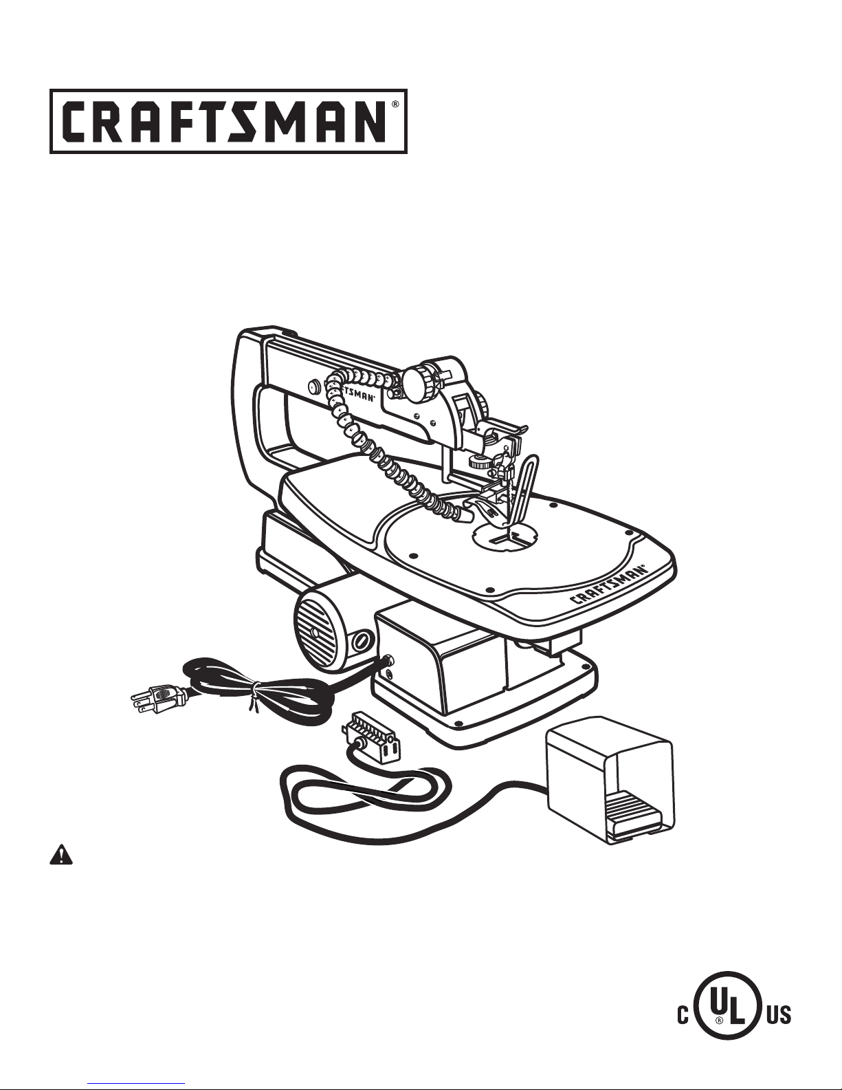
18 in. SCROLL SAW
VARIABLE SPEED
Model No.
315.216090
WARNING: To reduce the risk of injury,
the user must read and understand the
operator’s manual before using this product.
Customer Help Line: 1-800-932-3188
Sears, Roebuck and Co., 3333 Beverly Rd., Hoffman Estates, IL 60179 USA
Visit the Craftsman web page: www.sears.com/craftsman
983000-769
09-05
Save this manual for future reference
Page 2

3
TABLE OF CONTENTS
n Warranty ............................................................................................................................................................................2
n Introduction .......................................................................................................................................................................2
n General Safety Rules..................................................................................................................................................... 3-4
n Specific Safety Rules.........................................................................................................................................................5
n Symbols......................................................................................................................................................................... 6-7
n Electrical ............................................................................................................................................................................8
n Glossary of Terms ..............................................................................................................................................................9
n Features..................................................................................................................................................................... 10-11
n Tools Needed ................................................................................................................................................................. 12
n Loose Parts .................................................................................................................................................................... 12
n Assembly................................................................................................................................................................... 13-15
n Operation................................................................................................................................................................... 15-19
n Adjustments.................................................................................................................................................................... 20
n Maintenance.............................................................................................................................................................. 20-21
n Troubleshooting.............................................................................................................................................................. 22
n Notes .............................................................................................................................................................................. 23
n Exploded View and Parts List.................................................................................................................................... 24-27
n Parts Ordering/Service...................................................................................................................................... Back Page
WARRANTY
ONE YEAR FULL WARRANTY ON CRAFTSMAN TOOL
If this Craftsman tool fails due to a defect in material or workmanship within one year from the date of purchase, CON-
TACT THE NEAREST SEARS PARTS & REPAIR CENTER at 1-800-4-MY-HOME® and Sears will repair it, free of
charge. This warranty applies only while this product is in the United States.
If this tool is used for commercial or rental purposes, this warranty will apply for only ninety days from the date of pur-
chase.
This warranty gives you specific legal rights, and you may also have other rights which vary from state to state.
Sears, Roebuck and Co., Dept. 817WA, Hoffman Estates, IL 60179
INTRODUCTION
This tool has many features for making its use more pleasant and enjoyable. Safety, performance, and dependability
have been given top priority in the design of this product making it easy to maintain and operate.
2
Page 3

GENERAL SAFETY RULES
WARNING: Read and understand all instruc-
tions. Failure to follow all instructions listed below
may result in electric shock, fire, and/or serious
personal injury.
READ ALL INSTRUCTIONS
n KNOW YOUR POWER TOOL. Read the operator’s
manual carefully. Learn the applications and limitations
as well as the specific potential hazards related to this
tool.
n GUARD AGAINST ELECTRICAL SHOCK BY PRE-
VENTING BODY CONTACT WITH GROUNDED
SURFACES. For example: pipes, radiators, ranges,
refrigerator enclosures.
n KEEP GUARDS IN PLACE and in good working order.
n REMOVE ADJUSTING KEYS AND WRENCHES. Form
the habit of checking to see that keys and adjusting
wrenches are removed from tool before turning it on.
n KEEP WORK AREA CLEAN. Cluttered areas and
benches invite accidents. DO NOT leave tools or
pieces of wood on the tool while it is in operation.
n DO NOT USE IN DANGEROUS ENVIRONMENTS.
Do not use power tools in damp or wet locations or
expose to rain. Keep the work area well lit.
n KEEP CHILDREN AND VISITORS AWAY. All visitors
should wear safety glasses and be kept a safe
distance from work area. Do not let visitors contact
tool or extension cord while operating.
n MAKE WORKSHOP CHILDPROOF with padlocks,
master switches, or by removing starter keys.
n DON’T FORCE THE TOOL. It will do the job better and
safer at the feed rate for which it was designed.
n USE THE RIGHT TOOL. Do not force the tool or at-
tachment to do a job for which it was not designed.
n USE THE PROPER EXTENSION CORD. Make sure
the extension cord is in good condition. Use only a
cord heavy enough to carry the current the product will
draw. An undersized cord will cause a drop in line voltage resulting in loss of power and overheating. A wire
gauge size (A.W.G.) of at least 16 is recommended for
an extension cord 25 feet or less in length. If in doubt,
use the next heavier gauge. The smaller the gauge
number, the heavier the cord.
n DRESS PROPERLY. Do not wear loose clothing, neck-
ties, or jewelry that can get caught and draw you into
moving parts. Rubber gloves and nonskid footwear
are recommended when working outdoors. Also wear
protective hair covering to contain long hair.
n ALWAYS WEAR SAFETY GLASSES WITH SIDE
SHIELDS. Everyday eyeglasses have only impact-
resistant lenses, they are NOT safety glasses.
n SECURE WORK. Use clamps or a vise to hold work
when practical, it is safer than using your hand and
frees both hands to operate the tool.
n DO NOT OVERREACH. Keep proper footing and
balance at all times.
n MAINTAIN TOOLS WITH CARE. Keep tools sharp
and clean for better and safer performance. Follow
instructions for lubricating and changing accessories.
n DISCONNECT TOOLS. When not in use, before
servicing, or when changing attachments, blades, bits,
cutters, etc., all tools should be disconnected from
power source.
n AVOID ACCIDENTAL STARTING. Be sure switch is off
when plugging in any tool.
n USE RECOMMENDED ACCESSORIES. Consult the
operator’s manual for recommended accessories. The
use of improper accessories may result in injury.
n NEVER STAND ON TOOL. Serious injury could occur
if the tool is tipped.
n CHECK DAMAGED PARTS. Before further use of
the tool, a guard or other part that is damaged should
be carefully checked to determine that it will operate
properly and perform its intended function. Check for
alignment of moving parts, binding of moving parts,
breakage of parts, mounting and any other conditions
that may affect its operation. A guard or other part that
is damaged must be properly repaired or replaced by
an authorized service center to avoid risk of personal
injury.
n USE THE RIGHT DIRECTION OF FEED. Feed work
into a blade, cutter, or sanding spindle against the
direction or rotation of the blade, cutter, or sanding
spindle only.
n NEVER LEAVE TOOL RUNNING UNATTENDED.
TURN THE POWER OFF. Don’t leave tool until it
comes to a complete stop.
n PROTECT YOUR LUNGS. Wear a face or dust mask if
the cutting operation is dusty.
n PROTECT YOUR HEARING. Wear hearing protection
during extended periods of operation.
n DO NOT ABUSE CORD. Never carry tool by the cord
or yank it to disconnect from receptacle. Keep cord
from heat, oil, and sharp edges.
n USE OUTDOOR EXTENSION CORDS. When tool
is used outdoors, use only extension cords with
approved ground connection that are intended for use
outdoors and so marked.
n KEEP BLADES CLEAN, SHARP, AND WITH
SUFFICIENT SET. Sharp blades minimize stalling
and kickback.
n BLADE COASTS AFTER BEING TURNED OFF.
3
Page 4

5
GENERAL SAFETY RULES
n NEVER USE IN AN EXPLOSIVE ATMOSPHERE.
Normal sparking of the motor could ignite fumes.
n INSPECT TOOL CORDS PERIODICALLY. If damaged,
have repaired by a qualified service technician at
an authorized service facility. The conductor with
insulation having an outer surface that is green with
or without yellow stripes is the equipment-grounding conductor. If repair or replacement of the electric
cord or plug is necessary, do not connect the equipment-grounding conductor to a live terminal. Repair
or replace a damaged or worn cord immediately. Stay
constantly aware of cord location and keep it well away
from the rotating blade.
n INSPECT EXTENSION CORDS PERIODICALLY and
replace if damaged.
n KEEP TOOL DRY, CLEAN, AND FREE FROM OIL
AND GREASE. Always use a clean cloth when clean-
ing. Never use brake fluids, gasoline, petroleum-based
products, or any solvents to clean tool.
n STAY ALERT AND EXERCISE CONTROL. Watch
what you are doing and use common sense. Do not
operate tool when you are tired. Do not rush.
n DO NOT USE TOOL IF SWITCH DOES NOT TURN IT
ON AND OFF. Have defective switches replaced by an
authorized service center.
n USE ONLY CORRECT BLADES. Use the right blade
size, style, and cutting speed for the material and the
type of cut. Blade teeth should point down toward the
table.
n BEFORE MAKING A CUT, BE SURE ALL ADJUST-
MENTS ARE SECURE.
n BE SURE BLADE PATH IS FREE OF NAILS. Inspect
for and remove all nails from lumber before cutting.
n NEVER TOUCH BLADE or other moving parts during
use.
n NEVER START A TOOL WHEN ANY ROTATING COM-
PONENT IS IN CONTACT WITH THE WORKPIECE.
n DO NOT OPERATE A TOOL WHILE UNDER THE
INFLUENCE OF DRUGS, ALCOHOL, OR ANY
MEDICATION.
n WHEN SERVICING use only identical replacement
parts. Use of any other parts may create a hazard or
cause product damage.
n USE ONLY RECOMMENDED ACCESSORIES listed
in this manual or addendums. Use of accessories
that are not listed may cause the risk of personal
injury. Instructions for safe use of accessories are
included with the accessory.
n DOUBLE CHECK ALL SETUPS. Make sure blade is
tight and not making contact with saw or workpiece
before connecting to power supply.
4
Page 5

SPECIFIC SAFETY RULES
n FIRMLY CLAMP OR BOLT the tool to a workbench or
table at approximately hip height.
n KEEP HANDS AWAY FROM CUTTING AREA. Do not
reach underneath work or in blade cutting path with
your hands and fingers for any reason. Always turn the
power off.
n ALWAYS USE A CLAMP to secure the workpiece
when possible.
n ALWAYS SUPPORT LONG WORKPIECES while cut-
ting to minimize risk of blade pinching and kickback.
Saw may slip, walk or slide while cutting long or heavy
boards.
n BE SURE THE BLADE CLEARS THE WORKPIECE.
Never start the saw with the blade touching the
workpiece. Allow motor to come up to full speed
before starting cut.
n DO NOT FEED THE MATERIAL TOO QUICKLY. Do
not force the workpiece against the blade.
n NEVER reach behind, under, or within three inches
of the blade and its cutting path with your hands and
fingers for any reason.
n NEVER reach to pick up a workpiece, a piece of scrap,
or anything else that is in or near the cutting path of the
blade.
n AVOID AWKWARD OPERATIONS AND HAND
POSITIONS where a sudden slip could cause your
hand to move into the blade. ALWAYS make sure you
have good balance. NEVER operate the saw on the
floor or in a crouched position.
n IF ANY PART OF THIS SAW IS MISSING or should
break, bend, or fail in any way, or should any electrical
component fail to perform properly, shut off the power
switch, remove the plug from the power source, and
have damaged, missing, or failed parts replaced before
resuming operation.
n IF THE POWER SUPPLY CORD IS DAMAGED, it
must be replaced only by the manufacturer or by an
authorized service center to avoid risk.
n ALWAYS STAY ALERT! Do not allow familiarity (gained
from frequent use of the saw) to cause a careless mistake. ALWAYS REMEMBER that a careless fraction of
a second is sufficient to inflict severe injury.
n MAKE SURE THE WORK AREA HAS AMPLE LIGHT-
ING to see the work and that no obstructions will inter-
fere with safe operation BEFORE performing any work
using the saw.
n ALWAYS TURN OFF THE SAW before disconnecting
it to avoid accidental starting when reconnecting to
power supply. NEVER leave the saw unattended while
connected to a power source.
n TURN OFF TOOL and wait for saw blade to come to
a complete stop before moving workpiece or changing
settings.
n SAVE THESE INSTRUCTIONS. Refer to them
frequently and use to instruct other users. If you loan
someone this tool, loan them these instructions also.
WARNING: Some dust created by power sanding, sawing, grinding, drilling, and other construction activities
contains chemicals known to cause cancer, birth defects or other reproductive harm. Some examples of these
chemicals are:
• lead from lead-based paints,
• crystalline silica from bricks and cement and other masonry products, and
• arsenic and chromium from chemically-treated lumber.
Your risk from these exposures varies, depending on how often you do this type of work. To reduce your exposure
to these chemicals: work in a well ventilated area, and work with approved safety equipment, such as those dust
masks that are specially designed to filter out microscopic particles.
5
Page 6

7
SYMBOLS
Some of the following symbols may be used on this tool. Please study them and learn their meaning. Proper
interpretation of these symbols will allow you to operate the tool better and safer.
SYMBOL NAME DESIGNATION/EXPLANATION
V Volts
A Amperes
Hz Hertz
W Watt
min Minutes
Alternating Current
Direct Current
n
o
.../min
No Load Speed
Class II Construction
Per Minute
Wet Conditions Alert
Voltage
Current
Frequency (cycles per second)
Power
Time
Type of current
Type or a characteristic of current
Rotational speed, at no load
Double-insulated construction
Revolutions, strokes, surface speed, orbits etc., per minute
Do not expose to rain or use in damp locations.
Read The Operator’s Manual
Eye Protection
Safety Alert
No Hands Symbol
No Hands Symbol
No Hands Symbol
No Hands Symbol
Hot Surface
To reduce the risk of injury, user must read and understand
operator’s manual before using this product.
Always wear safety goggles or safety glasses with side
shields, or a full face shield when operating this product.
Precautions that involve your safety.
Failure to keep your hands away from the blade will result in
serious personal injury.
Failure to keep your hands away from the blade will result in
serious personal injury.
Failure to keep your hands away from the blade will result in
serious personal injury.
Failure to keep your hands away from the blade will result in
serious personal injury.
To reduce the risk of injury or damage, avoid contact with
any hot surface.
6
Page 7
SYMBOLS
The following signal words and meanings are intended to explain the levels of risk associated with this
product.
SYMBOL SIGNAL MEANING
DANGER:
WARNING:
CAUTION:
CAUTION:
Indicates an imminently hazardous situation, which, if not avoided, will
result in death or serious injury.
Indicates a potentially hazardous situation, which, if not avoided, could
result in death or serious injury.
Indicates a potentially hazardous situation, which, if not avoided, may
result in minor or moderate injury.
(Without Safety Alert Symbol) Indicates a situation that may result in
property damage.
SERVICE
Servicing requires extreme care and knowledge and
should be performed only by a qualified service technician. For service we suggest you return the product to
your nearest AUTHORIZED SERVICE CENTER for repair.
When servicing, use only identical replacement parts.
WARNING:
The operation of any power tool can result in foreign objects being thrown into your eyes, which can
result in severe eye damage. Before beginning power tool operation, always wear safety goggles or
safety glasses with side shields and a full face shield when needed. We recommend Wide Vision Safety
Mask for use over eyeglasses or standard safety glasses with side shields. Always use eye protection
which is marked to comply with ANSI Z87.1.
WARNING: To avoid serious personal injury, do not
attempt to use this product until you read thoroughly
and understand completely the operator’s manual.
Save this operator’s manual and review frequently for
continuing safe operation and instructing others who
may use this product.
SAVE THESE INSTRUCTIONS
7
Page 8
9
ELECTRICAL
EXTENSION CORDS
Use only 3-wire extension cords that have 3-prong
grounding plugs and 3-pole receptacles that accept the
tool’s plug. When using a power tool at a considerable
distance from the power source, use an extension cord
heavy enough to carry the current that the tool will draw.
An undersized extension cord will cause a drop in line
voltage, resulting in a loss of power and causing the motor
to overheat. Use the chart provided below to determine
the minimum wire size required in an extension cord. Only
round jacketed cords listed by Underwriter’s Laboratories
(UL) should be used.
**Ampere rating (on tool data plate)
0-2.0 2.1-3.4 3.5-5.0 5.1-7.0 7.1-12.0 12.1-16.0
Cord Length Wire Size (A.W.G.)
25' 16 16 16 16 14 14
50' 16 16 16 14 14 12
100' 16 16 14 12 10 —
**Used on 12 gauge - 20 amp circuit.
NOTE: AWG = American Wire Gauge
When working with the tool outdoors, use an extension
cord that is designed for outside use. This is indicated by
the letters “WA” on the cord’s jacket.
Before using an extension cord, inspect it for loose or
exposed wires and cut or worn insulation.
WARNING: Keep the extension cord clear of the
working area. Position the cord so that it will not get
caught on lumber, tools or other obstructions while
you are working with a power tool. Failure to do so
can result in serious personal injury.
WARNING: Check extension cords before each
use. If damaged replace immediately. Never use tool
with a damaged cord since touching the damaged
area could cause electrical shock resulting in serious
injury.
ELECTRICAL CONNECTION
This tool is powered by a precision built electric motor.
It should be connected to a power supply that is 120
volts, 60 Hz, AC only (normal household current). Do
not operate this tool on direct current (DC). A substantial
voltage drop will cause a loss of power and the motor will
overheat. If the saw does not operate when plugged into
an outlet, double check the power supply.
SPEED AND WIRING
The no-load speed of this tool is approximately 1,600
spm. This speed is not constant and decreases under
a load or with lower voltage. For voltage, the wiring in a
shop is as important as the motor’s horsepower rating. A
line intended only for lights cannot properly carry a power
tool motor. Wire that is heavy enough for a short distance
will be too light for a greater distance. A line that can
support one power tool may not be able to support two
or three tools.
GROUNDING INSTRUCTIONS
In the event of a malfunc
provides a path of least resistance for electric current to
reduce the risk of electric shock. This tool is equipped with
an electric cord having an equipment-grounding conductor and a grounding plug. The plug must be plugged into a
matching outlet that is properly installed and grounded in
accordance with all local codes and ordinances.
Do not modify the plug provided. If it will not fit the outlet,
have the proper outlet installed by a qualified electrician.
Improper connection of the equipment-grounding conductor can result in a risk of electric shock. The conductor
with insulation having an outer surface that is green with or
without yellow stripes is the equipment-grounding
conductor. If repair or replacement of the electric cord or
plug is necessary, do not connect the equipmentgrounding conductor to a live terminal.
Check with a qualified electrician or service personnel if
the grounding instructions are not completely understood,
or if in doubt as to whether the tool is properly grounded.
Repair or replace a damaged or worn cord immediately.
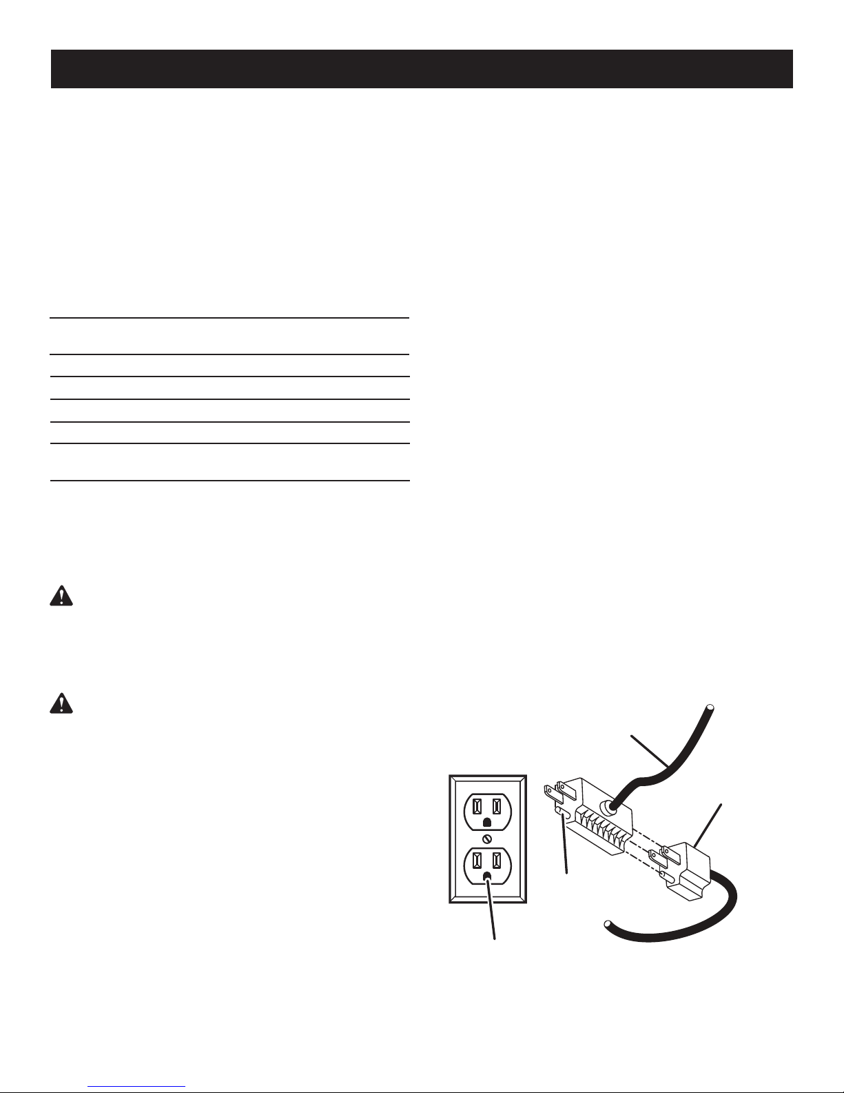
This tool is intended for use on a circuit that has an outlet
like the one shown in figure 1. It also has a grounding pin
like the one shown.
GROUNDING
tion or breakdown, grou
FOOT SWITCH
PLUG
PIN
nding
SCROLL SAW
PLUG
120V GROUNDED OUTLET
8
Fig. 1
Page 9

GLOSSARY OF TERMS
Anti-Kickback Pawls (radial arm and table saws)
A device which, when properly installed and maintained,
is designed to stop the workpiece from being kicked back
toward the front of the saw during a ripping operation.
Arbor
The shaft on which a blade or cutting tool is mounted.
Bevel Cut
A cutting operation made with the blade at any angle
other than 90° to the table surface.
Chamfer
A cut removing a wedge from a block so the end (or part
of the end) is angled rather than at 90°.
Compound Cut
A cross cut made with both a miter and a bevel angle.
Cross Cut
A cutting or shaping operation made across the grain or
the width of the workpiece.
Cutterhead (planers and jointer planers)
A rotating cutterhead with adjustable blades or knives.
The blades or knives remove material from the workpiece.
Dado Cut
A non-through cut which produces a square-sided notch
or trough in the workpiece (requires a special blade).
Featherboard
A device used to help control the workpiece by guiding it
securely against the table or fence during any ripping
operation.
FPM or SPM
Feet per minute (or strokes per minute), used in reference
to blade movement.
Freehand
Performing a cut without the workpiece being guided by a
fence, miter gauge, or other aids.
Gum
A sticky, sap-based residue from wood products.
Heel
Alignment of the blade to the fence.
Kerf
The material removed by the blade in a through cut or the
slot produced by the blade in a non-through or partial cut.
Kickback
A hazard that can occur when the blade binds or stalls,
throwing the workpiece back toward operator.
Leading End
The end of the workpiece pushed into the tool first.
Miter Cut
A cutting operation made with the workpiece at any angle
to the blade other than 90°.
Non-Through Cuts
Any cutting operation where the blade does not extend
completely through the thickness of the workpiece.
Pilot Hole (drill presses)
A small hole drilled in a workpiece that serves as a guide
for drilling large holes accurately.
Push Blocks (for jointer planers)
Device used to feed the workpiece over the jointer planer
cutterhead during any operation. This aid helps keep the
operator’s hands well away from the cutterhead.
Push Blocks and Push Sticks (for table saws)
Devices used to feed the workpiece through the saw
blade during cutting operations. A push stick (not a push
block) should be used for narrow ripping operations.
These aids help keep the operator’s hands well away from
the blade.
Resaw
A cutting operation to reduce the thickness of the workpiece to make thinner pieces.
Resin
A sticky, sap-based substance that has hardened.
Revolutions Per Minute (RPM)
The number of turns completed by a spinning object in
one minute.
Ripping or Rip Cut
A cutting operation along the length of the workpiece.
Riving Knife/Spreader/Splitter (table saws)
A metal piece, slightly thinner than the blade, which helps
keep the kerf open and also helps to prevent kickback.
Saw Blade Path
The area over, under, behind, or in front of the blade. As
it applies to the workpiece, that area which will be or has
been cut by the blade.
Set
The distance that the tip of the saw blade tooth is bent (or
set) outward from the face of the blade.
Snipe (planers)
Depression made at either end of a workpiece by cutter
blades when the workpiece is not properly supported.
Through Sawing
Any cutting operation where the blade extends completely
through the thickness of the workpiece.
Throw-Back
The throwing back of a workpiece usually caused by the
workpiece being dropped into the blade or being placed
inadvertently in contact with the blade.
Workpiece or Material
The item on which the operation is being done.
Worktable
Surface where the workpiece rests while performing a
cutting, drilling, planing, or sanding operation.
9
Page 10

11
FEATURES
PRODUCT SPECIFICATIONS
Throat ..............................................................................................................................................................................18 in.
Blade Size ...................................................................................................................................................... 5 in. plain or pin
No Load Speed ............................................................................................................................................. 500 - 1,600/min.
Input .................................................................................................................................... 120 V, 60 Hz, AC Only, 1.2 Amps
Net Weight..................................................................................................................................................................... 28 lbs.
LIGHT SWITCH
ON / OFF KNOB WITH
VARIABLE SPEED
TENSION KNOB
BLADE
BLADE
TENSION LEVER
DROP
FOOT
BLADE CLAMP
SCREWS
THROAT
PLATE
SAW
BLADE
DROP FOOT
LOCK KNOB
SAW
TABLE
SAWDUST
EXHAUST
ARMATURE
ACCESS
SAWDUST
BLOWER / LIGHT
BLADE
STORAGE DRAWER
10
BEVEL SCALE
TABLE
LOCK KNOB
FOOT SWITCH
Fig. 2
Page 11

FEATURES
KNOW YOUR SCROLL SAW
See Figures 2 - 3.
Before attempting to use this product, familiarize yourself
with all operating features and safety rules.
BEVEL SCALE
The bevel scale and indicator show the degree the saw
table is tilted.
BLADE CLAMP SCREWS
Blade clamp screws are used when changing saw blades.
BLADE STORAGE DRAWER
Attached under the left side of the table is a blade storage
drawer. It will hold up to 20 blades.
BLADE TENSION KNOB
Loosen or tighten blade tension by turning the blade tension knob.
DROP FOOT AND DROP FOOT LOCK KNOB
This foot should be lowered until it just rests on top of the
workpiece to prevent the workpiece from lifting, yet not so
much that the workpiece drags. The vertical portion provides a blade guard to prevent accidental blade contact.
FOOT SWITCH
Use the foot switch to conveniently turn your scroll saw
off and on.
LOCK POST
To prevent unauthorized use of the scroll saw, we suggest
that you disconnect it from the power supply and install
a padlock (not supplied) through the lock post beside the
knob, as illustrated, to lock the knob in the OFF position.
When the lock is properly installed and locked, the switch
is inoperable. Store the padlock key in another location.
LOCK POST
ON / OFF KNOB
WARNING: For your own safety, always push
the knob OFF when machine is not in use. Also, in
the event of a power failure, push knob OFF. Lock
the scroll saw switch OFF with a padlock. This will
prevent the machine from starting up again when the
power comes back on. Failure to heed this warning
can result in serious personal injury.
ON / OFF KNOB WITH VARIABLE SPEED
Pull the knob out to turn ON the scroll saw and push the
knob in to turn OFF the scroll saw. Turn the knob to adjust
the speed from the high speed of approximately 1,600
SPM (strokes per minute) to the low speed of approximately 500 SPM.
SAWDUST BLOWER / LIGHT
With a convenient ON / OFF switch, the sawdust blower/
light keeps the line of cut on the workpiece clean and
lighted for more accurate scroll cuts. Place the switch in
the ON position, then depress the foot switch to activate
the blower and/or light. For best results, always direct air
flow at the blade and the workpiece.
SAWDUST EXHAUST
This feature will allow you to attach any 1-1/4 in. vacuum
hose for easy sawdust collection.
SAW TABLE WITH THROAT PLATE
Your scroll saw has an aluminum saw table with tilt control
for maximum accuracy. The throat plate inserted in the
saw table allows for blade clearance.
SWITCH
A power switch turns the sawdust blower/light on and off.
TABLE LOCK KNOB
Allows you to tilt the table and lock it at any desired angle
from 5° left to 45° right.
PADLOCK
Fig. 3
11
Page 12

13
TOOLS NEEDED
The following tools (not included) are needed for making adjustments:
HEX KEY
PHILLIPS SCREWDRIVER
ADJUSTABLE WRENCH
SMALL COMBINATION SQUARE
The following items are included with the tool:
n Plain Blades (3)
n Pin Blades (2)
n Operator’s Manual (Not Shown)
PIN BLADE
FLAT HEAD SCREWDRIVER
Fig. 4
LOOSE PARTS
PLAIN BLADE
WARNING: The use of attachments or accessories not listed might be hazardous and could cause serious
personal injury.
12
Fig. 5
Page 13

ASSEMBLY
UNPACKING
This product has been shipped completely assembled.
n Carefully lift the saw from the carton and place it on a
level work surface.
n Inspect the tool carefully to make sure no breakage or
damage occurred during shipping.
n Do not discard the packing material until you have
carefully inspected and satisfactorily operated the tool.
n The saw is factory set for accurate cutting. After
assembling it, check for accuracy. If shipping has
influenced the settings, refer to specific procedures
explained in this manual.
n If any parts are damaged or missing, please call
1-800-932-3188 for assistance.
WARNING: If any parts are missing, do not operate
this tool until the missing parts are replaced. Failure
to do so could result in possible serious personal
injury.
WARNING: Do not attempt to modify this tool
or create accessories not recommended for use
with this tool. Any such alteration or modification is
misuse and could result in a hazardous condition
leading to possible serious personal injury.
WARNING: Do not connect to a power supply until
assembly is complete. Failure to comply could result
in accidental starting and possible serious personal
injury.
MOUNTING SCROLL SAW TO WORKBENCH
NOTE: All bolts should be inserted from the top. Install
the washers and nuts from the underside of the bench.
The supporting surface where the scroll saw is mounted
should be examined carefully after mounting to insure
that no movement during use can result. If any tipping or
walking is noted, secure workbench or supporting surface
before beginning cutting operations.
To Reduce Noise and Vibration:
You may wish to place a foam pad or piece of carpet
between the saw base and the workbench to help reduce
noise and vibration.
If a foam pad or piece of carpet is used, do not overtighten the mounting bolts. Leave some cushion between the
padding and the saw base to help absorb the noise and
vibration.
The size of the padding material should be approximately
24 in. x 12 in. x 1/2 in.
CLAMPING SCROLL SAW TO WORKBENCH
See Figure 6.
If the scroll saw is to be used in a portable application, it is
recommended that you fasten it permanently to a mounting board that can easily be clamped to a workbench or
other supporting surface. The mounting board should be
of sufficient size to avoid tipping of saw while in use. Any
good grade plywood or chipboard with a 3/4 in. thickness
is recommended.
n Mount saw to board using holes in saw base as a tem-
plate for hole pattern. Locate and mark the holes where
scroll saw is to be mounted.
�n Follow last three steps in previous section called
Mounting Scroll Saw to Workbench.
WARNING: To avoid serious personal injury from
unexpected tool movement, always securely mount
scroll saw to a workbench.
If the scroll saw is to be used in a permanent application,
we recommend that you secure it in a permanent location such as a workbench. When mounting the saw to a
workbench, holes should be drilled through the supporting
surface of the workbench.
n Each hole in the base of the saw should be bolted
securely using machine bolts, washers, and nuts (not
included). Bolts should be of sufficient length to accommodate the saw base, washers, nuts, and the
thickness of the workbench.
n Place scroll saw on workbench. Using the saw base as
a pattern, locate and mark the holes where the scroll
saw is to be mounted.
n Drill three holes through the workbench.
n Place scroll saw on workbench aligning holes in the
saw base with the holes drilled in the workbench.
n Insert all three bolts (not included) and tighten securely
with washers and nuts (not included).
13
C-CLAMP
SAW BASE
C-CLAMP
WORKBENCH
MOUNTING
BOARD
Fig. 6
Page 14

15
ASSEMBLY
If lag bolts are being used, make sure they are long
enough to go through holes in the saw base and the material to which the saw is being mounted.
If machine bolts are being used, make sure they are long
enough to go through holes in the saw base, the material
the saw is being mounted to, and the washers and nuts.
NOTE: It may be necessary to countersink washers and
nuts on the bottom side of mounting board.
SQUARING THE SAW TABLE TO THE BLADE
See Figures 7 - 8.
n Loosen the drop foot lock knob and move drop foot
rod all the way up. Retighten drop foot lock knob.
n Loosen the table lock knob to tilt the saw table until it
is approximately perpendicular or at a right angle to
the blade.
n Place a small combination square on the saw table
next to the blade to check squareness.
n Loosen the screw holding the scale indicator. Move
indicator to the 0° mark and securely tighten screw.
Remember, the bevel scale is a convenient guide but
DROP FOOT
LOCK KNOB
DROP
FOOT
should not be relied upon for precision. Make practice
cuts on scrap material to determine if your angle settings are correct.
n Adjust the drop foot to desired position and securely
retighten the drop foot lock knob.
SETTING THE TABLE FOR HORIZONTAL OR
BEVEL CUTTING
See Figures 8 - 10.
A bevel scale is located under the saw table as a convenient guide for setting the approximate saw table angle for
bevel cutting. When greater precision is required, make
practice cuts on scrap material and adjust the saw table
as necessary for your requirements.
NOTE: When cutting at angles, the drop foot should be
tilted so it is parallel to the saw table and rests flat against
the workpiece. To tilt the drop foot, loosen phillips screw,
tilt drop foot to the proper angle, then retighten screw.
n Loosen the table lock knob and push down on the right
side of the table. If the table stops at 0°, the zero degree stop is properly set. If the table stops somewhere
other than zero, adjust the zero degree stop.
To adjust:
n To access the zero degree stop, loosen the table lock
knob, and tilt the table with the right side all the way
down. Just under the front of the saw table is the zero
degree stop.
n Loosen the hex nut and rotate the hex bolt to raise
or lower the bolt as needed to adjust the zero degree
stop. Be sure to check to see that the table is square to
the blade.
DROP
FOOT ROD
SMALL
COMBINATION
SQUARE
TABLE
LOCK KNOB
Fig. 7
14
BEVEL
SCALE
SCALE
INDICATOR
ZERO DEGREE STOP
TABLE LOCK
KNOB
SCREW
Fig. 8
Page 15

ASSEMBLY
HEX BOLT
HEX NUT
ZERO DEGREE
STOP ASSEMBLY
n Now, by returning the table to the zero position, the
zero degree stop provides a quick reference to the
preset position.
The zero stop assembly can be rotated to the left and
Fig. 9
OPERATION
down out of the way, and the table can be angled up to
12˚ to the left.
NOTE: Make sure the zero degree stop is rotated all the
way down or it will contact the blade storage drawer as
you angle to the left.
ZERO DEGREE
STOP ASSEMBLY
Fig. 10
WARNING: Do not allow familiarity with tools to
make you careless. Remember that a careless fraction of a second is sufficient to inflict severe injury.
WARNING: Always wear safety goggles or safety
glasses with side shields when operating tools.
Failure to do so could result in objects being thrown
into your eyes resulting in possible serious injury.
WARNING: Do not use any attachments or acces-
sories not recommended by the manufacturer of
this tool. The use of attachments or accessories not
recommended can result in serious personal injury.
WARNING: To prevent serious personal injury,
never leave the saw unattended until the blade has
come to a complete stop.
APPLICATIONS
You may use this tool for the following purposes:
n Cutting wood, wood composition products, plastic,
and other fibrous material up to 2 in. thick
n Cutting nonferrous metals such as aluminum, brass,
and copper
WARNING: Before starting any cutting operation,
clamp or bolt the saw to a workbench. Never operate the saw on the floor or in a crouched position.
Failure to heed this warning can result in serious
personal injury.
BASIC OPERATION OF THE SCROLL SAW
Before starting a cut, watch the saw run. If you experience
excessive vibration or unusual noise, stop immediately.
Turn the saw off, remove the switch key, and unplug saw.
Do not restart until locating and correcting the problem.
NOTE: After the saw is turned ON, a hesitation before
blade movement is normal.
CUTTING PROCEDURES
n During each person’s learning period on this saw, it is
expected that some blades will break until proper use
and adjustments are learned.
�n Plan how to hold the workpiece from start to finish.
n Keep your hands away from the blade. Do not hand
hold pieces so small your fingers will go under the
blade guard.
�n Hold the workpiece firmly against the saw table.
n Use gentle pressure and both hands when feeding the
work into the blade. Do not force the work.
n Guide the workpiece into the blade slowly because the
teeth of the blade are very small and can only remove
material on the down stroke.
n Avoid awkward operations and hand positions where
a sudden slip could cause serious injury from contact
with the blade. Never place hands in blade path.
n To get accurate cuts, compensate for blade’s tendency
to follow the wood grain as you are cutting wood.
n Use extra supports (tables, saw horses, blocks, etc.)
when cutting large, small or awkward workpieces.
15
Page 16

17
OPERATION
n Never use another person as a substitute for a table
extension or as additional support for a workpiece that
is longer or wider than the basic saw table.
n When cutting irregularly shaped workpieces, plan your
work so it will not pinch the blade. Workpieces must
not twist, rock or slip while being cut.
AVOIDING INJURY
n Make sure saw is level and does not rock. Saw should
always be on a firm, level surface with plenty of room
for handling and properly supporting the workpiece.
�n Bolt saw to the support surface to prevent slipping,
walking or sliding during operations like cutting long,
heavy boards.
�n Turn saw off, remove switch key, and unplug cord from
the power source before moving the saw.
�n Do not remove jammed cutoff pieces until blade has
come to a full and complete stop.
�n Choose the right size and style blade for the material
and type of cut you plan to do.
�n Use only recommended accessories.
�n With the exception of the workpiece and related sup-
port devises, clear everything off the saw table before
turning the saw on.
�n Properly support round materials such as dowel rods
or tubing because they have a tendency to roll during
a cut causing the blade to “bite.” To avoid this, always
use a “V” block or clamp workpiece to a miter gauge
�n Before removing loose pieces from the saw table, turn
saw off and wait for all moving parts to stop.
REMOVING JAMMED MATERIAL
When backing out the workpiece, the blade may bind in
the kerf (cut). This is usually caused by sawdust clogging
the kerf or when the blade comes out of the blade holders. If this happens:
n Wait until saw has come to a full and complete stop.
n Place the switch in the OFF position.
n Unplug the saw from the power source.
n Remove the saw’s blade and the workpiece. See
Removing the Saw Blade.
n Wedge the kerf open with a flat screwdriver or wooden
wedge, then remove the blade from the workpiece.
WARNING: To avoid serious personal injury, turn
saw off and wait for all moving parts to stop before
removing loose pieces from the table.
Teeth/
Inch
10
7
13
Width Thickness
.110 in.
(2.8 mm)
.067 in.
(1.1 mm)
.037 in.
(0.5 mm)
.020 in.
(0.5 mm)
.020 in.
(0.5 mm)
.015 in.
(0.4 mm)
Speed or Strokes
Per Minute
500-1600
750-1250
500-1000
BLADE INFORMATION
�n Scroll saw blades wear out and must be replaced
frequently for best cutting results. Scroll saw blades
generally stay sharp for 1/2 hour to 2 hours of cutting,
depending on type of material and speed of operation.
�n When cutting wood, best results are achieved when
cutting wood less than one inch thick.
�n When cutting wood thicker than one inch, the user
must guide the workpiece very slowly into the blade
and take extra care not to bend or twist the blade while
cutting.
Material Cut
Popular size for cutting hard and soft woods
3/16 in. (4.8 mm) up to 2 in. (51 mm)
Plastics, paper, felt, bone, etc.
Extremely thin cuts on materials
3/32 in. (2.4 mm) to 1/2 in. (13 mm) thick
Wood, plastics
For tight radius work in thin materials
3/32 in. (2.4 mm) to 1/8 in. (3 mm)
Wood, veneer, bone, fiber, ivory, plastic, etc.
�n When choosing a blade, carefully consider the following:
• Very fine, narrow blades should be used to scroll cut
in thin material 1/4 in. (6 mm) thick or less.
• Most blade packages state the size or thickness and
type of material which that blade is intended to cut.
The package should also state the radius or size of
curve that can be cut with that blade size.
• Wider blades cannot cut curves as tight or as small
as thinner blades.
�n Blades wear faster when:
• Cutting plywood, hardwood, and other laminates.
• Cutting material thicker than 3/4 in.
• Side pressure is applied to the blade.
16
Page 17

OPERATION
CHOICE OF BLADE AND SPEED
The scroll saw accepts a wide variety of blade widths and
thicknesses for cutting wood and other fibrous materials.
It uses 5 in. long blades of either the pin end or plain end
style. The blade width and thickness and the number of
teeth per inch to use are determined by the type of material and the size of the radius being cut.
NOTE: As a general rule, always select narrow blades for
intricate curve cutting and wide blades for straight and
large curve cutting.
INSTALLING BLADES
See Figure 11.
Scroll saw blades wear out quickly and must be replaced
frequently for best cutting results. Expect to break some
blades while you learn to use and adjust the saw. Blades
generally stay sharp for 1/2 hour to 2 hours of cutting,
depending on the type of material and speed of operation.
PIN BLADES
Removing the Saw Blade:
n Turn off the saw and unplug from power source.
WARNING: Failure to turn the saw off and unplug
the saw from the power source could result in accidental starting causing possible serious injury.
TENSION
RELEASE
V-NOTCH
BLADE
SAW
BLADE
BLADE
CLAMP
SCREW
TENSION
KNOB
Fig. 11
n Pull up on the tension release.
n Turn blade tension knob clockwise to decrease (or
loosen) blade tension.
n Pushing up from under the saw table, remove the
throat plate.
n Loosen both the upper and lower blade clamp screws.
n Pull up on the blade and push down on the saw arm
to disengage the upper pin in the V-notch of the upper
blade holder. Push the blade downward to disengage
the lower pin in the lower blade holder.
n Remove the blade.
Replacing the Saw Blade:
n Turn off the saw and unplug from power source.
n Place the new blade through the opening in the saw
table with the teeth to the front of the saw and pointing
down toward the saw table. The pins on the blade go
under the blade holder in the lower blade holder.
n Pull up on the blade and press the upper arm down to
position the upper end of the blade in the V-notch in
the upper blade holder.
n Securely tighten the upper and lower blade clamp
screws.
n Push the tension release back down.
n Turn the blade tension knob counterclockwise until the
blade has the desired amount of tension.
n Replace the throat plate.
NOTE: If the blade touches the drop foot on either side
then the drop foot must be adjusted. See Adjusting Drop
Foot in the Adjustments section of this manual.
PLAIN BLADES
Removing the Saw Blade:
n Turn off the saw and unplug from power source.
n Pull up on the tension release.
n Turn blade tension knob counterclockwise to decrease
(or loosen) blade tension.
n Pushing up from under the saw table, remove the
throat plate.
n Loosen both the upper and lower blade clamp screws.
n Remove the blade.
Replacing the Saw Blade:
n Turn off the saw and unplug from power source.
n Place the new blade through the opening in the saw
table with the teeth to the front of the saw and pointing
down toward the saw table.
n Position blade and tighten the lower blade clamp
screw securely.
17
Page 18

19
OPERATION
SPM
1600
1250
1000
750
500
n Pull up on the blade and press the upper arm down to
position the upper end of the blade in the upper blade
holder.
n Securely tighten the upper blade clamp screw.
n Push the tension release back down.
n Turn the blade tension knob clockwise until the blade
has the desired amount of tension.
n Replace the throat plate.
NOTE: If the blade touches the drop foot on either side
then the drop foot must be adjusted. See Adjusting Drop
Foot in the Adjustments section of this manual.
DROP FOOT
See Figure 12.
To prevent the workpiece from lifting, the drop foot should
be adjusted so it just rests on the top of the workpiece.
The drop foot should not be adjusted so that the
workpiece drags.
Always retighten the drop foot lock knob after each adjustment has been made.
n Loosen the drop foot lock knob.
n Lower or raise the drop foot to the desired position.
n Retighten the drop foot lock knob.
The tall, front part of the drop foot acts as a blade guard
to prevent accidental contact with the blade.
LIGHT SWITCH
TURNING THE SCROLL SAW ON AND OFF
See Figures 13 - 14.
n Plug the foot switch into the power source.
n Plug the scroll saw into the foot switch.
Fig. 13
n Pull the ON / OFF knob out to the ON position. The
knob must remain in this position for the foot switch to
supply power to the saw.
n Depress foot switch to turn saw ON.
NOTE: After saw is turned on, a hesitation before blade
movement is normal.
n Release foot switch to turn saw OFF.
SWITCH
PULL / ON
PUSH / OFF
SPEED
INDICATOR
ON
OFF
DROP FOOT
LOCK KNOB
DROP FOOT
WARNING: Do not use this foot switch with any tool
other than 21609 Scroll Saw. Failure to follow this
warning may result in serious injury.
DROP
FOOT ROD
SAWDUST
BLOWER / LIGHT
Fig. 12
TO
DECREASE
TO
INCREASE
VARIABLE SPEED
See Figure 14.
The ON / OFF knob also controls the variable speed of
the saw. By turning the knob, the variable speed control
may be adjusted from the high speed of approximately
1,600 SPM to the low speed of approximately 500 SPM.
Turn the ON / OFF knob clockwise to increase strokes per
minute and counterclockwise to reduce the strokes per
minute.
18
Fig. 14
Page 19

OPERATION
This motor has an electronic control that regulates the
speed and provides overload protection to the motor. If
the motor fails to start after about two seconds, push the
knob OFF and disconnect the saw from the power source.
Refer to the troubleshooting chart.
NOTE: If the internal overload protector has been tripped,
pushing the ON / OFF knob OFF will reset it.
SCROLL CUTTING
For general scroll cutting, follow the pattern lines by pushing and turning the workpiece at the same time. Attempting to turn the workpiece without also pushing it could
cause the workpiece to bind or twist the blade.
INTERIOR SCROLL CUTTING
See Figure 15.
One convenient feature of a scroll saw is that it can be
used to make scroll cuts on the interior of a workpiece
without breaking or cutting through the edge or perimeter
of the board.
To make interior cuts in the workpiece:
n Remove the scroll saw blade as explained in the In-
stalling Blades section previously in this manual.
n Drill a 1/4 in. (6 mm) hole in the workpiece.
n Place the workpiece on the saw table with the drilled
hole over the access hole in the table.
n Install the blade through the hole in the workpiece;
adjust the drop foot and blade tension.
n When finished making the interior scroll cuts, simply
remove the blade from the blade holders as described
in the Installing Blades section, and remove the
workpiece from the saw table.
STACK CUTTING
See Figure 16.
After becoming well acquainted with the saw through
practice and experience, you may wish to try stack cutting. Stack cutting may be used when several identical
shapes need to be cut. Several pieces of wood may be
stacked on top and secured to each other before cutting. The wood pieces may be joined together by placing
double-sided tape between each piece or by wrapping
masking tape around the corners or ends of the stacked
wood. You must attach the stacked pieces of wood to
each other so they will move on the table as a single piece
of material.
WARNING: To avoid possible serious personal
injury, do not cut more than one loose piece of material at a time.
WOOD
PIECES
DRILL HOLE
WORKPIECE
TAPE
INTERIOR
CUT
Fig. 16
Fig. 15
19
Page 20

21
ADJUSTMENTS
WARNING: Before performing any adjustment,
make sure the tool is unplugged from the power
supply and the switch is in the OFF ( O ) position.
Failure to heed this warning could result in serious
personal injury.
ADJUSTING DROP FOOT
n Loosen the drop foot lock knob.
n Center the drop foot around the saw blade to the de-
sired position.
n Tighten the drop foot lock knob.
ADJUSTING BLADE TENSION
See Figure 17.
Adjustments to blade tension can be made at any time.
Check the blade tension by the sound the blade makes
when plucked like a guitar string. This method can be
developed with practice and requires knowing the scroll
saw.
Pluck the back straight edge of blade while turning blade
tension knob. The sound should be a musical note. The
sound becomes less flat as tension increases, and decreases with too much tension.
To adjust the blade tension:
n Turn off and unplug the saw from the power source.
BLADE
TENSION KNOB
Fig. 17
n Turn the blade tension knob clockwise to decrease (or
loosen) the blade tension.
NOTE: Be careful not to make the blade too loose.
Too little tension may cause the blade to bend or break
before the teeth wear out.
n Turn the blade tension knob counterclockwise to in-
crease (or tighten) blade tension.
NOTE: Be careful not to adjust the blade too tightly.
Too much tension may cause the blade to break as
soon as you start cutting.
MAINTENANCE
WARNING: When servicing, use only identical
replacement parts. Use of any other part may create
a hazard or cause product damage.
WARNING: Always wear safety goggles or safety
glasses with side shields during power tool operation
or when blowing dust. If operation is dusty, also wear
a dust mask.
GENERAL
Avoid using solvents when cleaning plastic parts. Most
plastics are susceptible to damage from various types of
commercial solvents and may be damaged by their use.
Use clean cloths to remove dirt, carbon dust, etc.
WARNING: Do not at any time let brake fluids,
gasoline, petroleum-based products, penetrating
oils, etc. come in contact with plastic parts. Chemicals can damage, weaken or destroy plastic which
may result in serious personal injury.
It has been found that electric tools are subject to
accelerated wear and possible premature failure when
they are used on fiberglass boats, sports cars, wallboard,
spackling compounds, or plaster. The chips and grindings
from these materials are highly abrasive to electric tool
parts such as bearings, brushes, commutators, etc.
Consequently, it is not recommended that this tool be
used for extended work on any fiberglass material, wallboard, spackling compounds, or plaster. During any use
on these materials it is extremely important that the tool is
cleaned frequently by blowing with an air jet.
n Keep the scroll saw clean.
n After cleaning the table top initially, apply a thin coat
of automobile type (paste) wax to the table top so the
wood slides easily while cutting.
n Do not allow pitch to accumulate on the saw table.
Clean with gum and pitch remover.
20
Page 21

MAINTENANCE
ARM BEARINGS
See Figure 18.
Lubricate the arm bearings after the first 10 hours of use.
Oil after every 50 hours of use or whenever there is a
squeak coming from the bearings.
n Carefully place the saw on its side as shown.
n Remove the rubber cap from the upper and the lower
arm of the saw.
n Squirt a few drops of SAE20 oil around the shaft end
and arm bearings. Let oil soak in overnight, remaining
in this position.
NOTE: Lubricate the bearings on the other side of the saw
in this same manner.
ARM BEARING
MOTOR BRUSHES
See Figure 19.
The saw has externally accessible motor brush assemblies that should be checked periodically for wear. When
either one of the two brushes becomes worn, replace
both brushes.
n Unplug the saw from the power source.
n Carefully place the saw on its side, exposing the under-
side of the saw housing.
n Using a flat blade screwdriver, remove the bottom
brush assembly cap through the access hole in the
base and the top brush assembly cap from the top of
the motor.
n Gently pry the brush assemblies out using a small
screwdriver, point of a nail, or paper clip.
n If one motor brush is worn down shorter than 1/4 in.,
replace both motor brushes. Do not replace one side
without replacing the other.
NOTE: Ensure curvature of brush matches curvature
of motor, and that motor brush moves freely in brush
tube. Use the blunt end of something thin (eraser end
of pencil, etc.) to push the motor brush into the tube
until it stays.
n Ensure the motor brush cap is oriented correctly
(straight), then tighten motor brush cap using a hand
powered screwdriver only. Do not overtighten.
ARM BEARING
Fig. 18
MOTOR
BRUSH
BRUSH
CAP
Fig. 19
21
Page 22

23
TROUBLESHOOTING
PROBLEM CAUSE SOLUTION
Motor will not run. Problem with ON / OFF switch, power
cord, foot switch, or outlet
Have worn parts replaced before using scroll saw again. Have the proper
outlet installed by a qualified electrician.
Motor defective
Blades breaking. Too much tension
Feeding too quickly
Wrong blade
Blade twisting in wood
Vibration (there is always some vibration when the saw is running).
Blade runout (blade not properly
aligned with arm motion).
Improper mounting of saw
Mounting surface
Loose table or table resting against
motor
Loose motor mounting
Blade holders out of line Realign blade.
Do not attempt any repair. Have
repaired by a qualified service technician.
Adjust tension.
Reduce feed rate.
Use narrow blades for cutting thin
wood or tight corners and turns; use
wide blades for thicker wood or wide
turns.
Reduce side pressure on blade; check
blade tension.
Check mounting.
Check mounting in manual.
Tighten table lock knob.
Tighten mounting screws.
22
Page 23

NOTES
23
Page 24

25
7
6
69
5
9
8
66
64
63
67
68
15
62
16
65
11
10
4
12
13
18
17
70
12
14
20
19
21
22
61
31
23
9
8
35
32
41
3
2
29
30
27
25
28
26
1
44
35
55
45
CRAFTSMAN 18 in. (457 mm) SCROLL SAW – MODEL NO. 216090
53
POINT INTO PART 38
SEE FIGURE B FOR INSERTION
50
46
52
49
52
54
48
47
46
56
57
25
58
24
59
60
42
43
40
41
36
37
38
39
35
FIGURE A
Page 25

37 E07000846157 Clamp (UC-15) ............................................... 3
38 A10003050105 * Screw (M5 x 10 Pan Hd.) ............................... 3
KEY PART
NO. NUMBER DESCRIPTION QTY.
39 979769001 * Hex Bolt (M6 x 20).......................................... 4
PARTS LIST FOR FIGURE A
CRAFTSMAN 18 in. (457 mm) SCROLL SAW – MODEL NO. 216090
40 180257000 Data Plate....................................................... 1
41 A03003050168 * Hex Bolt (M5 x 16).......................................... 3
42 979766001 * Screw (M4 x 30) ............................................. 2
43 979767001 Nozzle ............................................................ 1
44 979775001 Left Counterbalance....................................... 1
45 979762001 Link................................................................. 1
46 979758001 Ball Bearing (625ZZ)....................................... 2
47 180237100 Right Counterbalance .................................... 1
48 A36030508123 * Washer (M5) ................................................... 1
49 180238000 Screw ............................................................. 1
50 180242000 Spacer............................................................ 1
52 979776001 Set Screw (M6 x 6 mm).................................. 2
53 979759001 * Screw (M4 x 8) ............................................... 1
54 180250000 * Fixed Plate ..................................................... 1
55 180241000 Spacer............................................................ 1
56 A63000000051 * O-ring (P-5) .................................................... 1
57 A10003040180 * Screw (M4 x 18 mm) ...................................... 2
58 180106000 Table Spindle.................................................. 1
59 180110000 Table Pivot Stand ........................................... 1
60 A30003004005 * Hex Nut (M4) .................................................. 2
61 904222009 Label .............................................................. 1
62 180108000 Large Sponge................................................. 2
63 8180a00110 Pc Board ........................................................ 1
64 180112000 Inslulation Film ............................................... 1
65 180101000 Lead Wire ....................................................... 1
66 180109000 Small Sponge................................................. 1
67 8180A21000 Transformer Board Assembly......................... 1
68 180107000 Medium Sponge............................................. 1
69 180311000 Blade Drawn Bracket ..................................... 1
70 180607000 Foot Switch .................................................... 1
* STANDARD HARDWARE ITEM — MAY BE PURCHASED LOCALLY
1 180A02030 Upper Clamp Assembly ................................. 1
2 101069006 Saw Blade ...................................................... 3
3 180308000 Throat Plate.................................................... 1
4 180309000 Table............................................................... 1
5 979809001 Table Screw.................................................... 1
6 101072009 Saw Blade ...................................................... 2
KEY PART
NO. NUMBER DESCRIPTION QTY.
7 180310000 Blade Drawer ................................................. 1
8 A37130510060 * Washer (M5) ................................................... 3
9 979730001 * Screw (M5 x 8) ............................................... 3
10 A11003050083 * Screw (M5 x 8) ............................................... 2
11 180312000 Lock Handle ................................................... 1
12 979804001 * Washer (M6) ................................................... 2
13 180313000 Scale .............................................................. 1
14 180303000 Scale Bracket................................................. 1
15 180102000 Motor Cover ................................................... 1
16 180105000 Power Cord Assembly ................................... 1
17 E07050613002 Stain Relief ..................................................... 1
18 A10003060103 * Screw (M6 x 10) ............................................. 4
19 A18003050109 Clamp Screw.................................................. 2
20 980123001 Motor Assembly ............................................. 1
21 979786001 Brush Holder .................................................. 2
22 979785001 Brush Assembly ............................................. 2
23 979784001 Brush Cap ...................................................... 2
25 A10003050150 * Screw (M5 x 15) ............................................. 3
26 979772001 Indicator ......................................................... 1
27 979820001 * Hex Bolt (M5 x 15).......................................... 1
28 979821001 * Hex Nut (M5) .................................................. 1
29 979822001 Hex Bolt (Socket Hd. Special)........................ 1
30 A38030612019 * Washer (M6) ................................................... 1
31 979824001 Stopper .......................................................... 1
32 979825001 Spring Pin (M5 x 10 mm)................................ 1
35 180111000 Rubber Feet ................................................... 4
36 180113000 Base ............................................................... 1
25
Page 26

23
19
20
48
51
24
18
21
22
43
26
17
25
16
15
50
14
13
29
11
5
12
30
31
32
52
33
27
28
8
2
1
CRAFTSMAN 18 in. (457 mm) SCROLL SAW – MODEL NO. 216090
6
10
9
3
4
34
28
37
14
35
7
44
28
36
41
40
39
38
SEE FIGURE A
35
36
49
47
42
46
27
49
44
45
44
49
FIGURE B
26
Page 27

28 979765001 Bearing Bushing......................................... 4
29 A41001052340 Spring Pin (M5 x 23.4 mm) ........................ 1
30 180215000 Spring......................................................... 1
31 180205000 Adjustment Screw...................................... 1
32 A35030616160 * Washer (M6)............................................... 1
KEY PART
NO. NUMBER DESCRIPTION QTY.
33 180254000 Tension Knob ............................................. 1
PARTS LIST FOR FIGURE B
34 180201000 Upper Arm.................................................. 1
35 180223000 Bearing....................................................... 2
36 A42001050220 Spring Pin (M5 x 22 mm) ........................... 2
37 180a02040 Lower Clamp Assembly ............................. 1
38 180212000 Lower Arm.................................................. 1
39 180240000 Pin .............................................................. 1
40 180248000 Washer ....................................................... 4
41 180211000 Link ............................................................ 1
42 180a02070 Lead Wire Assembly .................................. 1
43 180245000 Retaining Ring (K7) .................................... 1
44 A11003040255 * Screw (M4 x 25) ......................................... 3
45 180114000 Warning Label ............................................ 1
46 A11003040350 * Screw (M4 x 35) ......................................... 3
47 180251000 Drop Foot Lock Knob ................................ 1
48 A95001050120 Set Screw (M5 x 12 mm)............................ 1
49 A11003040400 Screw, Ph. Hd. (M4 x 40 mm + S).............. 4
50 180262000 Led Label ................................................... 1
51 A10003040107 Screw, Ph. Hd. (M4 x 10 mm) .................... 4
52 180244000 Spacer........................................................ 1
983000769 Operator’s Manual
09-27-05
SEE BACK PAGE FOR PARTS ORDERING INSTRUCTIONS
CRAFTSMAN 18 in. (457 mm) SCROLL SAW – MODEL NO. 216090
The model number will be found on a plate attached to the motor housing. Always mention the model number in all correspondence regarding your
Scroll Saw or when ordering repair parts.
1 102032002 Tension Adjusting Knob ............................. 1
KEY PART
NO. NUMBER DESCRIPTION QTY.
2 979745001 Support Plate ............................................. 1
* STANDARD HARDWARE ITEM — MAY BE PURCHASED LOCALLY
3 979747001 Drop Foot ................................................... 1
4 180243000 Washer (M5) ............................................... 1
5 979749001 Hold Down Clamp...................................... 1
6 180a04010 Support Bar Assembly ............................... 1
7 A42001030109 Spring Pin (M3 x 10 mm) ........................... 1
8 A42001030140 Spring Pin (M3 x 14 mm) ........................... 1
9 180232000 Bellow ........................................................ 1
10 108217000 Blower ........................................................ 1
11 180253000 Blade Tension Lever................................... 1
12 180210000 Washer ....................................................... 1
13 180204000 Bracket....................................................... 1
14 A41001050150 Pin (M5 x 15 mm) ....................................... 2
15 8000200011 Vr Switch .................................................... 1
16 180226000 Switch ........................................................ 1
17 180259000 Switch Label .............................................. 1
18 180258000 Warning Label ............................................ 1
19 180260000 On/Off Knob Label ..................................... 1
20 180255000 On/Off Knob............................................... 1
21 166102100 Motor Pointer ............................................. 1
22 180219000 Switch Cover.............................................. 1
23 180229000 Led ............................................................. 1
24 180a02060 Sawdust Blower/Light................................ 1
25 180261000 Logo Plate .................................................. 2
26 979829001 Rubber Stopper ......................................... 4
27 089130100123 Arm Cover Assembly ................................. 1
27
Page 28

Get it fixed, at your home or ours!
Your Home
For repair – in your home – of all major brand appliances,
lawn and garden equipment, or heating and cooling systems,
no matter who made it, no matter who sold it!
For the replacement parts, accessories and
owner’s manuals that you need to do-it-yourself.
For Sears professional installation of home appliances
and items like garage door openers and water heaters.
®
1-800-4-MY-HOME
Call anytime, day or night (U.S.A. and Canada)
www.sears.com www.sears.ca
Our Home
(1-800-469-4663)
For repair of carry-in items like vacuums, lawn equipment,
and electronics, call or go on-line for the location of your nearest
Sears Parts & Repair Center.
1-800-488-1222
Call anytime, day or night (U.S.A. only)
www.sears.com
To purchase a protection agreement (U.S.A.)
or maintenance agreement (Canada) on a product serviced by Sears:
1-800-827-6655 (U.S.A.) 1-800-361-6665 (Canada)
Para pedir servicio de reparación
a domicilio, y para ordenar piezas:
1-888-SU-HOGAR
(1-888-784-6427)
SM
Au Canada pour service en français:
1-800-LE-FOYER
(1-800-533-6937)
www.sears.ca
MC
® Registered Trademark / TM Trademark /
® Marca Registrada /
MC
Marque de commerce / MD Marque déposée de Sears, Roebuck and Co. © Sears, Roebuck and Co.
TM
Marca de Fábrica / SM Marca de Servicio de Sears, Roebuck and Co.
SM
Service Mark of Sears, Roebuck and Co.
 Loading...