

Page 1
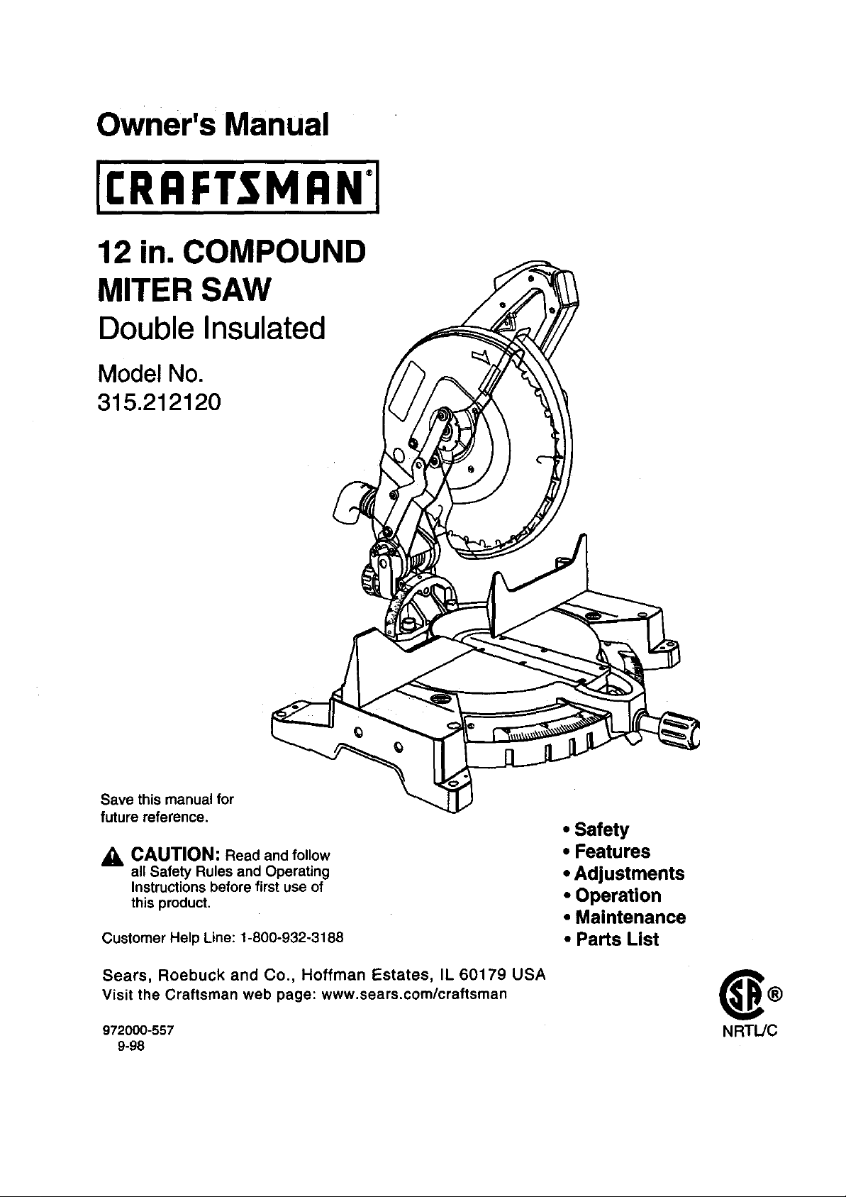
Owner's Manual
12 in. COMPOUND
MITER SAW
Double Insulated
Model No.
315.212120
Save this manual for
future reference.
CAUTION: Read and follow
all Safety Rules and Operating
Instructions before first use of
this product.
Customer Help Line: 1-800-932-3188
Sears, Roebuck and Co., Hoffman Estates, IL 60179 USA
Visit the Craftsman web page: www.sears.com/craftsman
972000-557
9-98
• Safety
• Features
• Adjustments
• Operation
• Maintenance
• Parts List
NRT_C
Page 2
• Table ofContents........................................................................................................................................... 2
• Warranty and Introduction........................................................... _.................................................................. 2
• Rules For Safe Operation ........................................................................................................................... 3-6
• Glossary ......................................................................................................................................................... 6
• ProductSpecificationsand Unpacking.......................................................................................................... 7
• Labels............................................................................................................................................................. 8
• LooseParts and Tools Needed...................................................................................................................... 9
• Features .................................................................................................................................................. 10-12
• Adjustments............................................................................................................................................. 13-19
• Operation................................................................................................................................................. 20-26
• Maintenance............................................................................................................................................ 27-28
• ExplodedView and Repair Parts List...................................................................................................... 30-35
• PartsOrdering/Service ............................................................................................................................... 36
FULL ONE YEAR WARRANTY
Ifthis productfails due to a defect in material or workmanshipwithinone yearfrom the dateof purchase,
Sears will repairitfree of charge.
Contact a Sears Service Center for repair.
Ifthis productis usedfor commercialor rentalpurposes,this warranty appliesonlyfor90 days from the date
of purchase.
Thiswarranty gives you specificlegal rights,and you may also have other rightswhich varyfromstate to state.
Sears, Roebuck and Co., Dept. 817WA, Hoffman Estates, IL 60179
II_li |',,[o]b]_l[O]lll[O]_i
Yoursew hasmany features for makingcutting
operationsmore pleasantand enjoyable.Safety,
performance and dependabilityhave been given top
priodtyinthe designof this sew makingit easy to
maintain andoperate.
_k Look for this symbol to point out important safety precautions. It means attention!l!
Your safety is involved.
_IL WARNING:
The operationof any powertool can result inforeignobjects beingthrown intoyour eyes,
whichcan resultin severe eye damage. Before beginningpowertool operation,always
wear safety gogglesor safetyglasseswith side shieldsand a fullface shieldwhen needed.
We recommendW'_leVisionSafety Mask for use over eyeglassesor standardsafety
glasses withside shields, availableat Sears Retail Stores.
_k CAUTION: Carefully read throughthis entire
owner'smanual beforeusingyour newsew. Pay
close attentionto the RulesFor Safe Operation,
and all Safety AlertSymbols includingDanger,
Warningand Caution. Ifyou use yoursew
propedyand only forwhat it is intended,you will
enjoyyears of safe, reliableservice.
2
Page 3
ThepurposeofsafetysymbolsIs to attract your attention to poulbio dangers. The safety Symbols, and
the explanations with them, deserve your careful attention and uhderstanding. The safety warnings do
not by themselvse eliminate any.JFlanger.The Instructions or warnings they give are not 8ubetltutee for
proper accident prevention inseams.
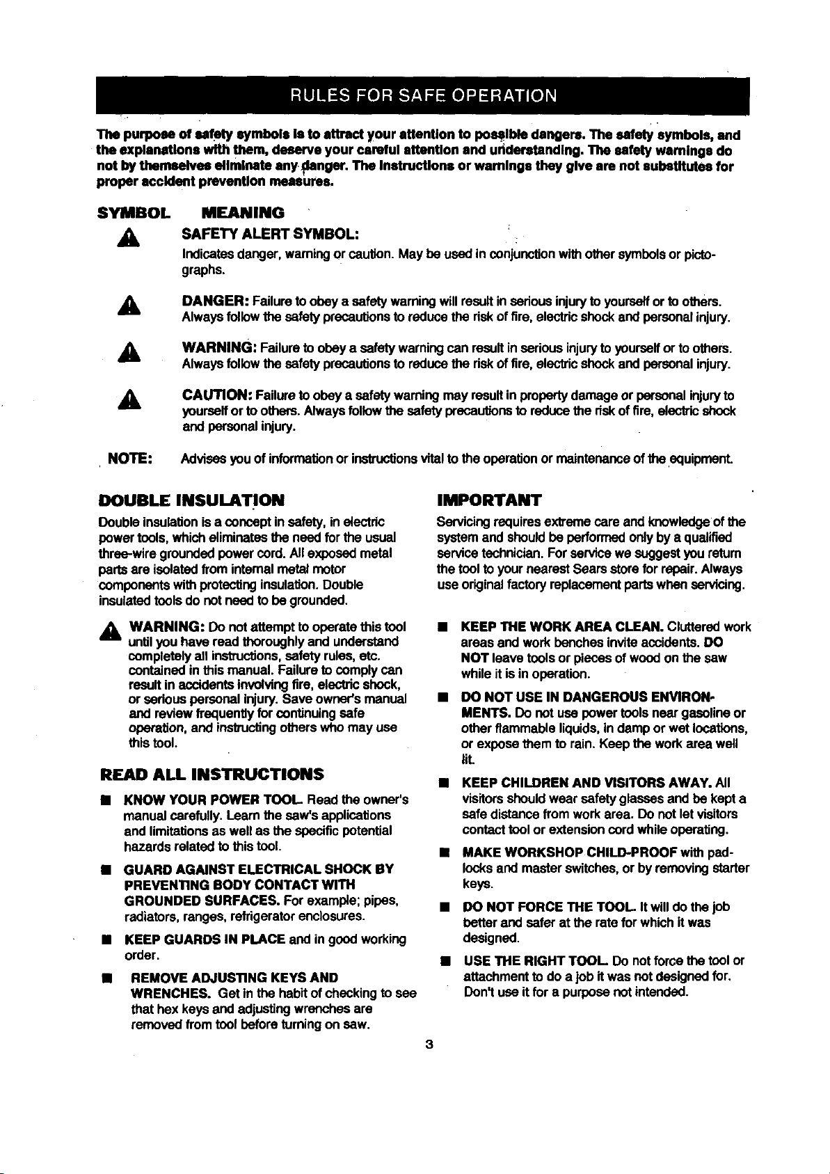
SYMBOL
A
A
A
A
NOTE: Advisesyou of information or instructions vitalto the operationor maintenanceoftheequipment.
DOUBLE INSULATION
Doubleinsulationisa concept in safety,inalectric
powertools,which eliminatesthe need forthe usual
three-wiregroundedpower cord. Allexposedmetal
partsare isolatedfrom intemal metalmotor
components withprotectinginsulation.Double
insulatedtoolsdo not needto be grounded.
A WARNING: Do not attemptto operatethis tool
untilyou have read thoroughlyand understand
completelyall instructions,safety rules, etc.
contained inthis manual. Failureto comply can
resultin accidentsinvolvingfire, electricshock,
or sedous personal injury.Save owner'smanual
and reviewfrequently for continuing safe
operation,and instructingotherswho may usa
this tool.
READ ALL INSTRUCTIONS
• KNOW YOUR POWER TOOL Readthe owner's
manual carefully. Learnthe saw's applications
and limitationsas wellas the specificpotential
hazards relatedto this tool.
• GUARD AGAINST ELECTRICAL SHOCK BY
PREVENTING BODY CONTACT WITH
GROUNDED SURFACES. Forexample; pipes,
radiators,ranges, refrigeratorenclosures.
• KEEP GUARDS IN PLACE and ingood working
order.
REMOVE ADJUSTING KEYS AND
WRENCHES. Get In the habitofchecking to see
that hexkeysand adjusting wrenchesare
removedfromtool before turningon saw.
MEANING
SAFETY ALERT SYMBOL:
Indicatesdanger,warningor caution. May be used inconjunctionwithother symbolsorpicto-
graphs.
DANGER: Failuretoobey a safetywarningwillresultinsedousinjuryto yourselforto others.
Alwaysfollowthesafety precautionsto reducethe riskof fire, electricshockand personalinjury.
WARNING: Failureto obeya safety warningcan resultin seriousinjurytoyourselfor to others.
Alwaysfollowthesafety precautionsto reducethe riskoftire, electricshockand personalinjury.
CAUTION: Failureto obeya safetywarningmayresultin properlydamage or personalinjuryto
yourselfor to others.Alwaysfollowthe safety precautionsto reducethe dsk offire, electricshock
and personalinjury.
IMPORTANT
Servicingrequiresextremecare and knowledgeofthe
systemand shouldbe performed onlyby a qualified
service technician.For service we suggestyou return
the tool to your nearestSears storefor repair.Always
useoriginalfactory replacementpartswhen servicing.
KEEP THE WORK AREA CLEAN. Clutteredwork
areas and work benches inviteaccidents.DO
NOT leave tools or pieces ofwood on the saw
whileit isin operation.
DO NOT USE IN DANGEROUS ENVIRON-
MENTS. Do not use power toolsneargasolineor
otherflammable liquids,indamp or wet locations,
or expose them to rain. Keep the workarea wall
IlL
KEEP CHILDREN AND VISITORS AWAY. All
visitorsshouldwear safety glasses and be kept a
safe distancefrom work area. Do notletvisitors
contacttoolor extensioncord while operating.
• MAKE WORKSHOP CHILD-PROOF with pad-
locksand masterswitches,or byremoving starter
keys.
• DO NOT FORCE THE TOOL Itwilldo thejob
betterand safer at the rate for whichit was
designed.
• USE THE RIGHT TOOL Do notforce the toolor
attachment to do a job itwas not designedfor.
Don't use itfor a purposenotintended.
Page 4
RULES FOR SAFE OPERATION (Continued)
USE THE PROPER EXTENSION CORD. Make
sure yourextensioncord is ingood condition.
When usingan extensioncord, be sure to use
one heavy enoughto carrythe currentyour
productwill draw.An undersizedcordwill cause
a drop in linevoltage resultingin lossof power
and overheating.A wiregage size (A.W.G.) of at
least 14 is recommendedfor an extensioncord
25 feet orless in length. If in doubt, usethe next
heaviergage. The smallerthe gage number,the
heavierthe cord.
m
INSPECT EXTENSION CORDS PERIODI-
CALLY and replace ifdamaged.
m
DRESS PROPERLY. DOnotwear looseclothing,
gloves, neckties,rings, bracelets,or other
jewelry. They can get caughtand draw you into
movmgparts.Rubber glovesand nonslipfoot-
wear are recommendedwhen workingoutdoors.
Alsowear protectivehaircovering tocontain long
hair.
ALWAYS WEAR SAFETY GLASSES WITH
SIDE SHIELDS. Everydayeyeglasses have only
impact-resistantlenses;they are NOT safety
glasses.
PROTECT YOUR LUNGS. Wear a face or dust
mask ifthe cuffingoperationisdusty.
PROTECT YOUR HEARING. Wear hearing
protectionduringextended periodsof operation.
SECURE WORK. Useclampsora viseto hold
workwhen practical.It's safer than usingyour
handand it frees beth handstooperate tool.
DO NOT OVERREACH. Keep proper footingand
balance at all times.
MAINTAIN TOOLS WITH CARE. Keep tools
sharpand clean for betterand safer perfor-
mance. Followinstructionsfor lubricatingand
changingaccessories.
DISCONNECT ALL TOOLS. When not in use,
before servicing, or when changingattachments,
blades, bits,cutters, etc., all toolsshouldbe
disconnected.
AVOID ACCIDENTAL STARTING. Be sure
switchisoff when pluggingin.
USE RECOMMENDED ACCESSORIES. The
useof improperaccessoriesmay cause risk of
injury.
M
NEVER STAND ON TOOL Serious injurycould
occur ifthe toolis tippedor ifthe blade is unin-
tonflonally contacted.
CHECK DAMAGED PARTS. Before further use
m
of the tool, a guardor other partthat isdamaged
shouldbe carefullychecked todetermine that it
willoperate properlyand perform itsintended
function.Check for alignmentof movingparts,
bindingof movingparts,breakage ofparts,
mountingand any other conditionsthatmay
affectitsoperation. A guardor other partthat is
damaged must be properlyrepaired or replaced
by a qualified servicetechnicianat a Sears store
to avoid riskof personalinjury.
NEVER LEAVE TOOL RUNNING UNAT-
TENDED. TURN THE POWER OFF. Do not
leave tool untilitcomes to a complete stop.
FIRMLY CLAMP OR BOLT yourmiter saw to a
workbenchor table at approximatelyhipheight.
USE ONLY CORRECT BLADES. Do not use
bladeswithincorrect size holes Never usa blade
washersor blade boltsthat are defectiveor
incorrect.The maximumbladecapacity ofyour
saw is 12 in.
KEEP BLADES CLEAN, SHARP AND WITH
SUFFICIENT SET. Sharp bladesminimize
stallingand kickback.
DO NOT REMOVE THE SAW'S BLADE
GUARDS. Never operatethe saw with anyguard
or cover removed. Make sure all guardsare
operatingproperlybeforeeach use.
KEEP HANDS AWAY FROM CUTnNG AREA.
Keep handsaway from blades. Do not reach
underneathworkor aroundor underthe blade
whileblade is rotating. Do notattemptto remove
cutmaterial when blade is moving.
_i, WARNING: Blade coasts after turnoff.
DO NOT ABUSE CORD. Never yankcord to
disconnect it from receptacle. Keep cordfrom
heat, oil, and sharpedges.
INSPECT TOOL CORDS PERIODICALLY and if
damaged, have repaired bya qualified service
technicianat a Sears store.Stay constantly
aware of cord locationand keep it well away
fromthe rotatingblade.
USE OUTDOOR EXTENSION CORDS, When
tool is used outdoors,use onlyextensioncords
withapprovedgroundconnectionthat are
intendedfor use outdoorsand so marked.
DO NOT USE TOOL IF SWITCH DOES NOT
TURN IT ON AND OFF. Havedefectiveswitches
replaced bya qualifiedservicetechnicianat a
Sears store.
KEEP TOOL DRY, CLEAN, AND FREE FROM
OIL AND GREASE. Always use a clean cloth
whencleaning. Never use brake fluids,gasoline,
petroleum-basedproducts,or any solventsto
clean tool.
Page 5

RULES FOR SAFE OPERATION (Continued)
ALWAYS SUPPORT LONG WORKPIECES to
minimizedsk of bladeI_nchingand kickback.
Saw may slip,walk, or slide whilecuttinglongor
heavy beards.
BEFORE •AKING A CUT, BE SURE ALL
ADJUSTMENTS ARE SECURE.
GUARD AGAINST KICKBACK. Kickbackoccurs
when the blade stallsrapidlyand workpioceis
drivenback towardsthe operator. It can pullyour
hand intothe bladeresultingin sedous personal •
injury. Stay out of blade pathand turnswitchoff
immediatelyifblade bindsor stalls.
AVOID CUTTING NAILS. Inspectforand
remove all nailsfrom lumberbefore cuffing.
ALWAYS USE A CLAMP to secure the work-
piece when possible.
NEVER TOUCH BLADE or othermovingparts
during use.
NEVER START A TOOL WHEN THE BLADE IS
IN CONTACT WITH WORKPIECE. Allow motor
to come up tofull speed beforestartingcut.
• AKE SURE THE MITER TABLE AND SAW
ARM (BEVEL FUNCtiON) ARE LOCKED IN
POSITION BEFORE OPERATING YOUR SAW.
Lockthe miter table by securelytighteningthe
miter lockhandle. Lockthe saw arm (bevel
funciton)by securelytighteningthe bevel lock
knob.
NEVER USE A LENGTH STOP ON THE FREE
SCRAP END OF A CLAMPED WORKPIECE.
NEVER hold ontoor bindthe free scrapend of
the workpiocein anyoperation. Ifa workclamp
and lengthstopare used together,they must
both be installedon the same side ofthe saw
table to preventthe saw from catchingthe loose
end and kickingup.
NEVER cut more than one piece at a time. DO
NOT STACK more than one workpieceon the
saw table at a time.
NEVER PERFORM ANY OPERATION "FREE-
HAND". Alwaysplace the workpieceto becuton
the mitertable and position it firmlyagainst the
fence as a backstop. Always usa the fence.
NEVER hand holda workpiecethatistoosmall
to be clamped. Keep hands clear of the no hands
zone.
NEVER reach behind,under,or withinthree
inches.ofthe bladeand itscuttingpath withyour
handsand fingersfor any reason.
NEVER reach to pickup a workpioce,a piece of
scrap,or anythingelse that is in or near the
cuffingpathofthe blade.
AVOID AWl(WARD OPERATIONS AND HAND
POSITIONS where a suddenslipcouldcause
yourhandto move intothe blade. ALWAYS
make sure you havegood balance. NEVER
operateyour miter sew on the flooror in a
crouchedposition.
NEVER standor have any partof your bodyin
linewiththe path of the saw blade.
ALWAYS release the powerswitchand allowthe
saw bladeto stop rotatingbefore raisingitoutof
theworkpiece.
DO NOT TURN THE •OTOR SWITCH ON AND
OFF RAPIDLY. Thiscould cause the saw blade
to loosenand couldcreate a hazard. Shouldthis
ever occur,standclear and allow the sew blade
to come toa complete stop. Disconnectyoursaw
fromthe power supplyand securelyretightenthe"
blade bolt.
REPLACEMENT PARTS. Allrepairs,whether
electricalor mechanical, shouldbe madeby
qualifiedservice technicianat a Sears store.
WARNING: When servicing use onlyidentical
Craftsmanreplacementparts. Use of any other
parts may create a hazard or cause product
damage.
NEVER USE IN AN EXPLOSIVE ATMO-
SPHERE. Normalsparkingofthe motorcould
ignitefumes.
NEVER leave the miter saw unattendedwhile
connectedtoa power source.
POLARIZED PLUGS. To reducethe dskof
electricshock, thistoolhas a paladzed plug(one
bladeis widerthan the other).This plugwillfitin
a polarized outletonly one way. If the plugdoes
not fit fullyin the outlet,reverse the plug. Ifit still
does notfit, contacta qualifiedelectricianto
installthe properoutlet. Do not changethe plug
in any way.
IF ANY PART OF THIS MITER SAW IS MISS-
ING or shouldbreak, band, or fail inany way, or
shouldany electricalcomponentfail to perform
properly,shutoff the power switch,removethe
mitersaw plugfromthe power sourceandhave
damaged, missing,or failed partsreplaced
beforeresumingoperation.
DO NOT OPERATE THIS TOOL WHILE UN-
DER THE INFLUENCE OF DRUGS, ALCOHOL,
OR ANY MEDICATION.
5
Page 6
RULES FOR SAFE OPERATION (Continued)
ALWAYS STAY ALERT! Do not allow familiarity
(gained from frequent use of your saw) to cause
a careless mistake. ALWAYS REMEMBER that
a careless fraction of a second is sufficient to
inflict severe injury.
STAY ALERT AND EXERCISE CONTROL
Watch what you ere doing and usecommon
sense. Do not operate tool when you are tired.
Do not rush.
SAVE THESE INSTRUCTIONS
Arbor
The shafton which a bladeor cuttingtool ismounted.
,Bevel Cut
Acuttingoperation made withthe blade at any angle
otherthan 90° to the mitertable.
Cresacut
Acuttingor shapingoperationmade acrossthe grain
ofthe workplace.
Compound Miter Cut
Acompoundmitercut isa cut made usinga miter
angleand a bevel angle atthe same time.
Freehand
Performinga cutwithoutusinga fence, mitergage,
fixture,workclamp, or other properdevice to keepthe
workpiecefrom twis_ngor movingduringthe cut.
Gum
A sticky,sap based residuefrom wood products.
Mlter Cut
A cuttingoperation made with the blade at anyangle
otherthan 90" to the fence.
Resin
A sticky,sap bass substancethat has hardened.
Revolutions Per Minute (RPM)
The numberof toms completedby a spinningobject
inone minute.
Saw Blade Path
The area over, under,behind, or in frontof the blade.
As it appliesto the workplace,that area whichwillbe,
or has been, cut by the blade.
MAKE SURE THE WORK AREA HAS AMPLE
UGHTING tosee thework and that noobstruc-
tionswill interferewith safe operationBEFORE
performing any workusingyour saw.
ALWAYS TURN OFF SAW before disconnecting
it, to avoid accidentalslarlJngwhen re-connect-
ingto powersupply.
SAVE THESE INSTRUClrlONS. Refer tothem
frequently and usa to instructotherusers. Ifyou
loan someonethis tool,loan them these instruc-
tionsalso.
Set
The distancethat the tip ofthe sawblade toothis bent
(or sat) outwardfrom the face of the blade,
Throw-Back
Throwing of aworkplacein a mannersimilartoa
kickback.Usuallyassociated witha cause otherthan
the kerf closing,suchas a workplacenot being
againstthe fence, beingdroppedintothe blade,or
being placedinadvertentlyincontact withthe blade.
Through Sawing
Any cuttingoperationwhere the blade extends
completely throughthe thickness of the workplace.
Workplace
The item on whichthe cuttingoperationis beingdone.
The surfacesofa workpieceare commonlyreferredto
as faces, ends, and edges.
Zero Clearance Throat Plate
A plasticthreat plate insertedinthe miter tablethat
allowsfor blade clearance. When you makeyour first
cutwithyour compoundmitersaw, the saw blade cuts
a slotthrough the throat platethe exact widthofthe
blade. Thisprovidesfor a zero clearancekerf that
minimizesworkplecetaar-out.
No Hands Zone
The area between the marked linesonthe leftand
rightsideof the mitertable base. Thiszone is
identifiedby no hands zone labels placedinsidethe
marked lineson the miter table base.
6
Page 7
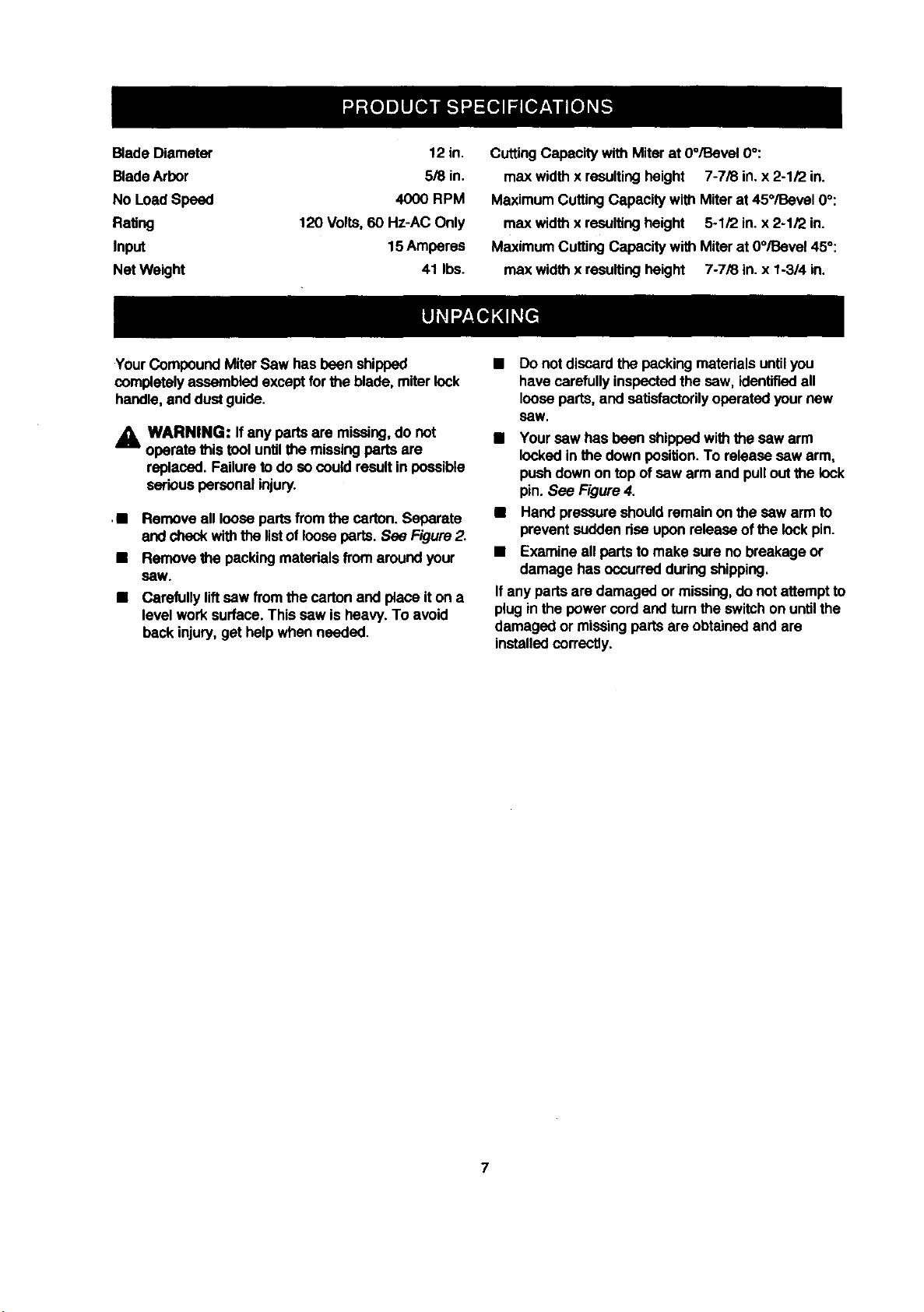
BladeDiameter 12in.
Blade Arbor 5/8 in.
No LoadSpeed 4000 RPM
Rating 120 Volts,60 Hz-AC Only
Input 15 Amperes
Nat Weight 41 Ibs.
CuttingCapacity with Miterat 0°/Bevel 0°:
max widthx resultingheight 7-7/8 in. x 2-1/2 in.
MaximumCuttingCapacity with Miterat 45°/Bevel 0°:
max widthx resultingheight 5-1/2 in. x 2-1/2 in.
MaximumCuttingCapacity with Miter at 0°/Bevel 450:
max widthx resultingheight 7-7/8 in.x 1-3/4 in.
YourCompound MiterSaw has been shipped
completelyassembledexcept forthe blade, miter lock
handle,and dust guide.
A WARNING: Ifany parts are missing,do not
operate this tool untilthe missing partsare
replaced. Failure todo so could result in possible
seriouspersonalinjury.
• Remove all loosepartsfromthe carton. Separate
andcheckwiththe listof looseparts. See Figure2.
• Remove the packingmaterials fromaround your
seW.
• Carefully liftsaw fromthe carton and place iton a
level work surface.This saw isheavy. To avoid
back injury,get helpwhen needed.
• Do notdiscardthe packingmaterials untilyou
have carefullyinspectedthe sew, identifiedall
looseparts, and satisfactorilyoperated yournew
SeW.
• Your sew has been shippedwiththe sew arm
lockedin the downposition.To release sew arm,
pushdown on top of sew arm and pullout the lock
pin. See Figure4.
• Hand pressureshould remainon the saw arm to
preventsudden dse uponreleaseof the lockpin.
• Examine all partsto make sure no breakage or
damage has occurredduringshipping.
Ifany partsare damaged or missing,do notattemptto
plug inthe power cordand turn the switchon untilthe
damaged or missingpartsare obtainedand are
installedcorrectly.
Page 8
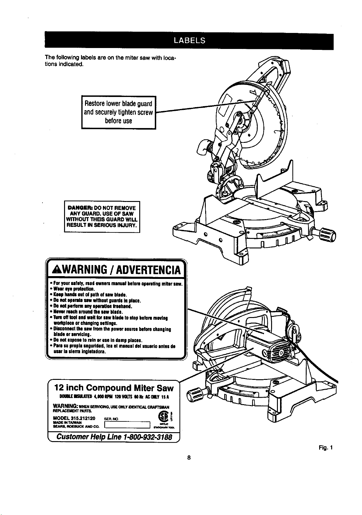
Thefollowinglabelsareonthemitersawwithloca-
tionsindicated,
Restorelowerbladeguard
andsecurelytightenscrew
beforeuse
DANGER: DO NOT REMOVE
ANY GUARD. USE OF SAW
WITHOUT THEIS GUARD WILL
RESULT IN SERIOUS INJURY.
tRNING/ ADVERTENI
• FOryoursafety,read owners manual beforeoparutln
• Wear eye protection,
• Keep bends Outut path of sawblade.
• DOnotoparath sawwithout guardsin place.
• O0 notperlorm anyoporutlonIreahad.
• Never roacharound the saw blade.
• Turnutf fool end waitfor saw blade to stopbefore moving
wad(piece or cbanoinOsethnos.
• Disconnectthe caw fromthe powersourcebalers changing
blade orservicing.
• Oo nutexposetorain or use In dampplaces.
• Pare se propiasepuridsd, lea el manual del usuorioautosde
userla €lerfa inplctadora.
12 inch Compound Miter Saw
WARNING:wa_,senwoNo, use ONLYmemlc_.
MOOEL 315.212120 SER.NO.
MADE INTAIWAN
. Customer Help Line 1-800-932-3188
Sl_l_m _OL
Fig. 1
8
Page 9
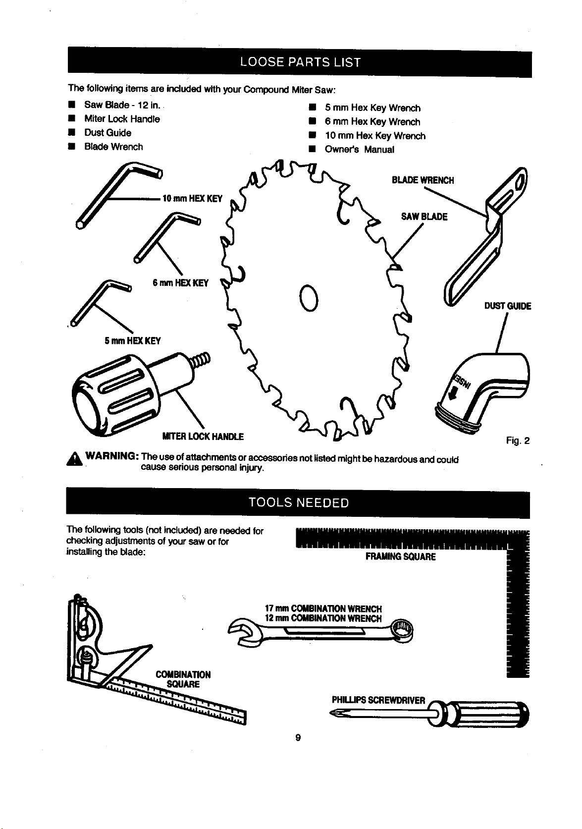
Thefollowingitemsare included with yourCompoundMiter Saw:
• SawBlade- 12in.,
• Miter Lock Handle
• Dust Guide
• BladeWrench
F IOtamHEXKEY
,_ 6mm HEXKEY
5 mmHEXKEY
• 5 mm Hex Key Wrench
• 6 mm Hex Key Wrench
• 10 mm Hex KeyWrench
• Owner's Manual
BLADEWRENCH
SAWBLADE
DUSTGUIDE
MITERLOCKHANDLE
A WARNING: The useo!attachmentsoraccessoriesnotlistedmightbe hazardousand coud
The followingtools(notincluded)are needed for
checking adjustmentsofyour sew or for
installingthe blade:
cause serious personalinjury.
FRAMINGSQUARE
17 mm COMBINATIONWRENCH
WR?H
COMBINATION
SQUARE
PHIUJPSSCREWDRIVER
Fig. 2
9
Page 10
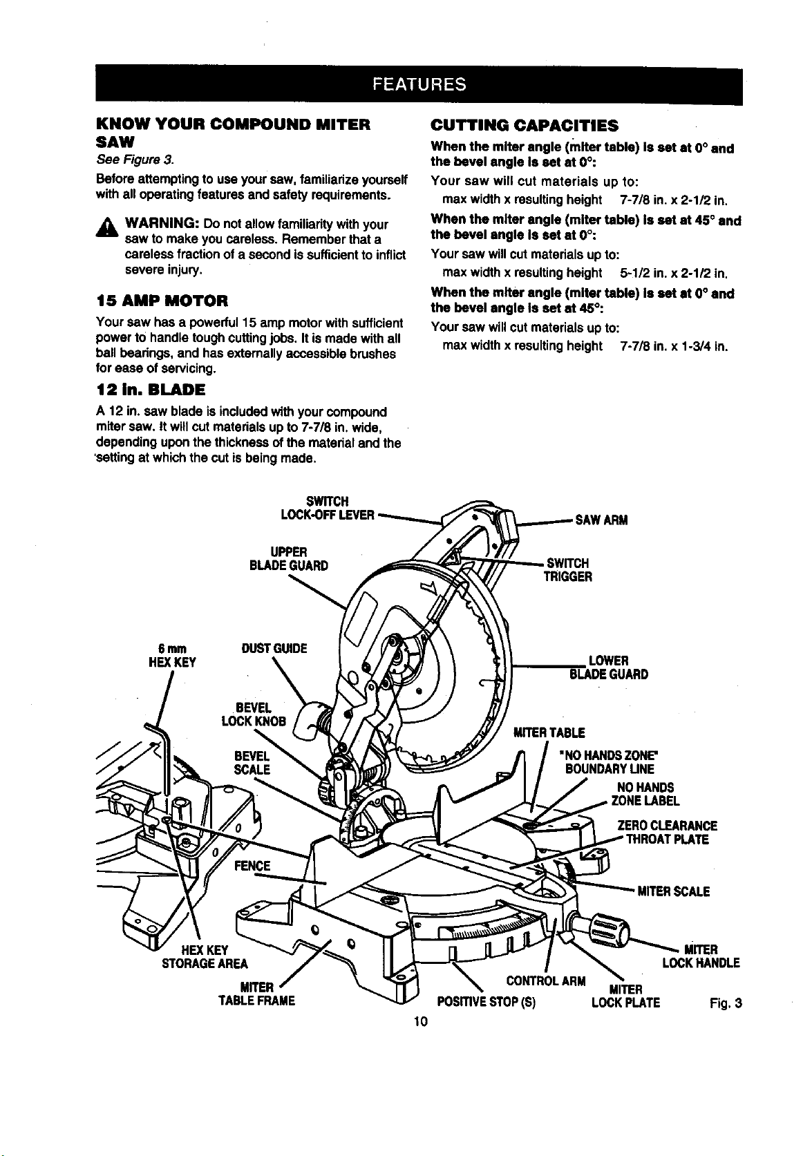
KNOW YOUR COMPOUND MITER
SAW
See Figure3.
Beforeattemptingto useyour saw, familiarizeyourself
withall operatingfeatures and safety requirements.
_i WARNING: Do notallowfamiliaritywithyour
saw to make youcareless. Rememberthat a
careless fractionof a second issufficientto inflict
severe injury.
15 AMP MOTOR
Your saw has a powerful15 amp motorwithsufficient
powerto handle toughcuttingjobs. It is made withall
hellbearings, and has extemally accessiblebrushes
for ease of servicing.
12 in. BLADE
A 12 in. saw blade is includedwithyourcompound
miter saw. it willcut materialsupto 7-7/8 in. wide,
dependinguponthe thicknessof the material and the
'settingat which the cut isbeing made.
SWITCH
LOCK-OFFLEVER
CUTTING CAPACITIES
When the miter angle (raRer table) Is set at 0° and
the bevel angle Is set at 0°:
Your saw win cut materials up to:
max widthx resultingheight 7-7/8 in. x 2-1/2 in.
When the miter angle (miter table) Is set at 45° and
the bevel angle Is eat at O°:
Yoursaw will cutmaterials upto:
max widthx resultingheight 5-1/2 in. x 2-1/2 in.
When the miter angle (miter table) Is set at O° and
the bevel angle Is sat at 45°:
Yoursaw will cutmaterials upto:
max widthx resultingheight 7-7/8 in. x 1-3/4 in.
UPPER
BLADEGUARD
6 mm DUSTGUIDE
HEXKEY
\
STORAGEAREA
HEXKEY __
MRER
TABLEFRAME
TRIGGER
LOWER
BLADEGUARD
MITERTABLE
"NOHANDSZONE"
BOUNDARYMNE
CONTROLARM
PosmvE STOP(S) LOCKPLATE
10
NOHANDS
ZEROCLEARANCE
PLATE
' MRERSCALE
MmER
LOCKHANDLE
MITER
Fig. 3
Page 11
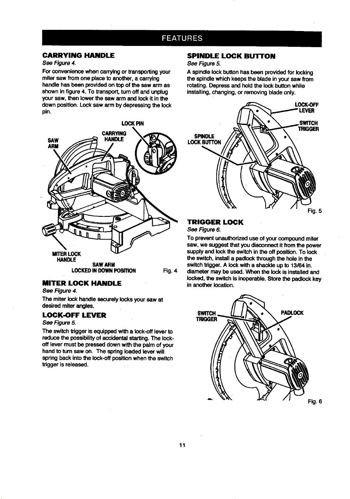
CARRYING HANDLE
See Figure4.
Forconvenience when carryingor transportingyour
miter saw from one place to another, a carrying
handle hasbeen providedon top of the saw arm as
shownin figure 4. To transport,turnoff and unplug
your saw, then lowerthe saw arm and lockit inthe
down position: Locksaw arm bydepressing the lock
pin.
SPINDLE LOCK BUTrON
See Figure5.
A spindlelockbuttonhas been providedfor locking
the spindlewhichkeeps the blade in yoursaw from
rotating.Depressand hold the lock button while
installing,changing,or removingbladeonly.
LOCK-OFF
LOCKPiN
CARRYING %%
SAW
ARM
HANDLE
\
MITERLOCK
HANDLE
LOCKEDINDOWNPOSITION
MITER LOCK HANDLE
See Figure 4.
The miterlockhandle securely locksyour saw at
desired miter angles.
LOCK-OFF LEVER
See Figure5.
The switchtriggerisequippedwith a rock-offleverto
reducethe possibilityof accidentaletartJng.The lock-
off lever must be pressed downwiththe palm of your
handto turn saw on. The spdngloaded lever will
springback intothe lock-offposition when the switch
triggeris released.
SAWARM
Fig. 4
,SWITCH
TRIGGER
SPINDLE
LOCKBUTrON
Fig. 5
TRIGGER LOCK
See Figure6.
To preventunauthorizeduse of your compound miter
saw, we suggestthat youdisconnectit fromthe power
supplyand lockthe switchinthe offposition. To lock
the switch, installa padlockthrough the hole inthe
switchtrigger.A lock witha shackleup to 13/64 in.
diameter may be used.When the lockis installedand
locked,the switchis inoperable.Store the padlockkey
in anotherlocation.
SWITCH PADLOCK
TRIGGER
11
Fig. 6
Page 12

POSITIVE STOPS ON MITER TABLE
Positivestops have been providedat 0°, 15°, 22-1/'Z',
31.62_, and 45° on beththe left and rightside of the
mitertable.
BEVEL LOCK KNOB
The bevel lockknobsecurely locksyourcompound
mitersaw at desired hovelangles. Positive stop
adjustmentscrewshave been providedon each side
ofthe saw arm. These adjustmentscrewsare for
makingfine adjustmentsat 0° and 45°. Sea pages 18
and 19.
ELECTRIC BRAKE
An electricbrake has been providedto quicklystop
blade rotationafterthe switchisreleased.
FENCE
The fence on yourcompound miter saw has been
providedto holdyour workpiecesecurelyagainst
when making all cuts.
SELF-RETRACTING LOWER BLADE
GUARD
The lowerblade guard is made ofshock-resistant,
see-throughplasticthat providesprotectionfrom each
side ofthe blade. Itretractsover the upper blade
guardas the saw is lowered into the workpiece.
MOUNTING HOLES
See Figure 7.
Your compound mitersaw shouldbe permanently
mountedto a firm supportingsurfacesuchas work-
bench. Four 7/16 in, boltholes have been providedin
the saw base forthis purpose.Each of the four
mountingholesshould be belted securelyusing7/16
in. machine bolts,lockwashers, and hex nuts(not
included).Beltsshouldbe of sufficientlengthto
accommodatethe saw base, lockwashers, hex nuts,
and the thicknessofthe workbench.
Tightenall four belts securely.
The holepattern for an 20 in. x 30 in.workbench is
shownin Figure 7. Carefully checkthe workbench
after mounting to make sure that no movement can
occurduring use. If anytipping, sliding,or walkingis
noted, secure the workbenchto the floorbefore
operating.
_k WARNING: Alwaysmake sureyour compound
miter saw is securelymountedto a workbenchor
an approved workstand.Failure todo so could
resultin an accident resultingin possibleserious
personal injury.
30in.
21-3/4in.
Fig. 7
Nextto the belt holes,four nail holes have been
providedinthe saw basefor temporarilymounting
yourcompoundmiter saw. Use 4 nailsabout2-1/2 in.
longto secureyour saw temporarily.
Note: Make sure the surfacewhere you are mounting
yoursaw, isthick enoughto accommodatethe nails
being used.
ELECTRICAL CONNECTION
Your saw has a precisionbuiltelectricmotor. It should
be connected to a power supply that Is 120 volts,
60 Hz, AC only (normal household current). Do not
operatethis toolon direct current(DC). A substantial
voltagedropwill cause a lossof power and the motor
willoverheat, if yourtool does not operate when
pluggedintoan outlet,double-checkthe power
supply.
& WARNING: The operationofany saw can
resultin foreign objectsbeing thrown intoyour
eyes, which can resultin severe eye damage.
Beforestartingpower tooloperation,always
wear safely gogglesorsafety glasseswithside
shieldsand a fullface shieldwhen needed. We
recommendwide vision safety maskfor use over
eyeglassesor standardsafetyglasses withside
shields,
WARNING: Do net attemptto modifythis toolor
create accessories not recommendedfor use
with this tool. Any suchalteration or modification
is misuseand couldresult in a hazardous
condition leadingto possible serious personal
injury.
12
Page 13

_, WARNING: To preventaccidentalstartingthat
couldcause possibleseriouspersonalinjury,
assemble all partsto your saw beforeconnecting
itto powersupply.Saw shouldnever be
connectedtopower supplywhen you are
assemblingparts, makingadjustments,installing
or removingblades, or when not in use.
Asmentioned previouslyyoursew has been factory
assembled and adjusted.The miterlock handle, dust
guide,and blade are the onlypartsthat haveto be
installed.
MITER LOCK HANDLE
See Figure 8.
To installthe miter lockhandle,place the threaded
studon the end of the miterlockhandle intothe
threaded holeinthe controlarm. Tumclockwiseto
tighten.
TO
LOOSEN
TO INSTALL BLADE
See Figures 10, 11, and 12.
WARNING: A 12 in. bladeis the maximum
blade capacity ofyour saw. Never use a blade
that is toothickto allow outerblade washerto
engage withthe flatsonthe spindle.Larger
bladeswill come in contact with the blade
guards,while thicker blades willprevent the
blade screwfrom secudngthe blade onthe
spindle.Eitherof these situationscould resultin
a sedousaccidentand cancause serious
personalinjury.
• Unplugyoursew.
& WARNING: Failuretounplugyoursaw could
resultinaccidentalstartingcausingpossible
sedouspersonal injury.
Push downon the sew arm and pullout the lock
[)into release saw arm. Raise sew armto itsfull
raisedposition.Be cautious, sew arm is spring
loadedto raise.
• Loosenthe phillipsscrew on the blade bolt
cover untilbladeboltcover can be raised.
See Figure 10.
• Gently raisethe lowerblade guard bracketso that
the lower bladeguard and blade belt cover can be
rotatedup and back to expose the bladebelt. See
Figures10.
CONTROL MITER
MITER ARM TABLE
LOCKHANDLE Fig. 8
DUST GUIDE
Sea Figure 9.
To installthe dust guide, place the end marked
INSERT over the exhaustport in the upperblade
guard.Tum the guide sothat the open end is facing
downor toward the rear of the saw.
EXHAUST
PORT
DUSTGUIDE
Fig. 9
LOWER
BLADEGUARD
PHILUPS
SCREW
BLADE
BOLT
ILADE
GUARDBRACKET Fig. 10
13
Page 14

LOWER
BLADEGUARD
ARROW
• Wipe a dropof oil ontoinner blade washer and
outerblade washerwhere theycontactthe blade.
BLADE
BOLTCOVER
TO
ONSPINDLE
INNERBLADE
TO WASHERWITH
TIGHTEN DOUBLE'D"FLATS
BLADEBOLT BLADE
OUTERBLADEWASHER
wm.I DOUBLE"D"FLATS Fig. 11
• Depress the spindlelock buttonand rotatethe
blade belt untilthe spindlelooks.See Figure 12.
• Usingthe bladewrench provided,loosenand
remove the blade belt.
Note: The blade belt hasleft handthreads. Tum
blade belt clockwiseto loosen.
• Remove outerblade washer. Do not remove
inner blade washer.
(s)
& WARNING: If innerblade washer has been
removed, replace it beforeplacing blade on
spindle. Failureto do so couldcause an accident
since bladewill not tightenproperly.
• Fit saw blade insidelower bladeguardand onto
spindle.The bladeteeth pointdownwardat the
frontof saw as showninfigure 1I.
_k CAUTION: Alwaysinstall the blade with the
blade teeth and the arrow printedon the sideof
the blade pointingdown at the frontof the saw.
The directionof blade rotationisalso stamped
withan arrow on the upperblade guard.
• Replace outer blade washer. The double"D"fiats
on the blade washers alignwiththe fiats on the
spindle.
• Depressspindle lockbuttonand replace blade
belt.
Note: The blade bolt has left hand threads.Turn
blade boltcounterclockwise to tighten.
• Tightenblade belt securely.
• Remove the blade wrenchand storeit in a safe
place for futureuse.
• Replace the lowerbladeguard and blade belt
cover.
• Retightenphillipsscrew securingblade bolt cover.
Tightenscrew securely. See Figure 11.
SPINDLE
BuTroN
Fig. 12
_k WARNING: To preventdamage to the spindle
lock,always allowmotorto come toa comPlete
stop before engagingspindle lock.Make sure the
spindlelockbuttonis not engaged before
reconnectingsew into powersource.
Your compoundmiter saw has been adjustedat the
factoryfor making veryaccurate cuts. However,some
of the componentsmight have been jarred out of
alignmentduringshipping. Also,over a periodof time,
readjustmentwill probablybecome necessarydue to
wear. After unpackingyoursaw, checkthe following
adjustmentsbefore you beginusingsaw. Makeany
readjustmentsthat are necessaryand peflodically
checkthe parts alignmentto make sure thatyoursaw
is cuttingaccurately.
A WARNING: Your saw shouldnever be
connectedto power supplywhen you are
assemblingparts, makingadjustments,installing
or removingblades, or when not inuse.
Disconnectingyour saw willpreventaccidental
startingthat could cause serious injury.
14
Page 15

Note: Many of the illustrationsinthis manual show
onlyportionsof yourcompound mitersaw. Thisis
intentionalso that we can clearlyshow points being
made in the illustrations.Neveroperate your saw
withoutall guards securelyin place and ingood
operatingcondition.
CUTTING A SLOT IN THE ZERO
CLEARANCE THROAT PLATE
In order to use your compound miter saw, youmust
cuta slotthrough the zeroclearance throat plate to
allowfor bladeclearance.To cutthe slot,set your
saw at 0 degreesmiter, turnsew on and allowthe
bladeto roachfull speed, then carefullymake a
straightcut as far as it willgo through the throat plate.
Turn your saw off and allowthe bladeto cometo a
complete stopbefore raisingthe saw arm.
Next, adjustthe bevel angle to45 degrees, turn your
sew on and allowthe bladeto reach full speed, then
carefully make another cutthroughthe zero clearance
throatplate. The throatplate will than be wide enough
toallow the blade to pass through it at any anglefrom
0 to 45 degrees.
SQUARING THE MITER TABLE
TO THE FENCE
See Figures 13- 16.
• Unplugyoursaw.
FRAMING
FENCE
SQUARE
MITER LOCKHANDLE
LOCKPLATE
VIEWOFMITERTABLESQUAREWITHFENCE
ANDCORRECTLYADJUSTED
FENCE
MITER TABLE r
ZEROCLEARANCE
THROATPLATE
MITER
Fig. 13
MITERTABLE
_k WARNING: Failureto unplugyour saw could
resultin accidentalstartingcausingpossible
seriouspersonal injury.
• Push downon the sew arm and pulloutthe lock
pin to release the sew arm.
• Raise saw arm to itsfull raised position.
• Loosen the miter lockhandle approximatelyone-
half turn.
• Depressthe miter lockplate and rotatethe miter
table until the pointer on the controlarm is posi-
tioned at 0°.
Release the miterlock plate and securelytighten
the miterlock handle.
Lay a framing square flaton the mitertable. Place
one leg of the square againstthe fence. Place the
other leg of the square beside the zero clearance
throat plate in the mitertable. The edge of the
squareand the zero clearance throat plate in
the mitertable shouldbe parallel as shownin
figure 13.
If the edge ofthe framing square and the zero
clearancethroat plate in the miter table are not
parallelas shown infigures 14 and 15, adjust-
mentsare needed.
FRAMING ZEROCLEARANCE
SOUARE THROATPLATE
VIEWOFMITERTABLENOTSQUAREWITH
FENCE,ADJUS1MENTEAREREQUIRED
Fig. 14
FENCE
MITERTABLE
FRAMING ZEROCLEARANCE
SQUARE THROATPLATE
VIEWOFMITERTABLENOTSQUAREWITH
FENCE,ADJUSTMENTSAREREQUIRED
Fig. 15
15
Page 16

• Using a 6 mm hex key, loosenthe socket head
screwssecudngthe fence. See Figure 16.Adjust
the fence leftor dght untilthe framingsquare and
zero clearance throat plate are parallel.
• Retightenthe screwssecurelyand recheckthe
fence-to-tablealignment.
FENCE
FRAMING
SQUARE
6 mmSOCKET
HEADSCREWS
6 mmSOCKET
HEADSCREWS
Fig. 16
SQUARING THE SAW BLADE TO THE
FENCE
See Figures 17- 20.
• Unplugyoursew.
& WARNING: Failureto unplugyoursew could
result inaccidental startingcausingpossible
seriouspersonalinjury.
• Pullthe sew arm all theway down and engage
the lock pin to holdthe saw arm intransport
position;
Loosen the miter lock handle approximately
one-half turn.
Depress the miter lock plate and rotate the miter
table untilthe pointer on the control arm is
positioned at 0°.
Release the miterlockplate and securelytighten
the miter lockhandle.
• Laya framing square fiat on the mitertable. Place
one leg ofthe square against the fence. Slide the
otherleg of the square againstthe fiat pert of sew
blade.
Note: Make surethat the square contactsthe fiat
part of the sew blade, not the bladeteeth.
MITER BLADE
TABLE MITER
FENCE
MITER BLADE
TABLE MITER
VIEWOFBLADENOTSQUAREWITH
FENCE,ADJUSTMENTSAREREOUIRED Rg. 18
MITER BLADE
TABLE MITER
VIEWOF BLADE NOTSQUAREWITH
FENCE,ADJUSTMENTSARE REQUIRED
LOCKPLATE
MITER
VIEWOFBLADE LOCKHANDLE
SQUAREWITHFENCE Fig. 17
LOCKPLATE
LOCKPLATE
Fig. 19
16
Page 17

• The edge of the squareand the saw bladeshould
be parallel as shownin figure 17.
• Ifthe front or back edge of the saw bladeangles
away from the square as showninfigures 18 and
19, adjustmentsare needed.
• Usingthe 10 mm hex key provided,loosenthe
sockethead screwsthat secure the mounting
brackettothe mitertable. See Figure20.
f0 mmSOCKET
10mln ._
HEXKEY"_"
Loosenbevel lockknoband set saw arm at 0°
bevel (blade set 90° to mitertable). Tighten bevel
lockknob.
Place a combinationsquareagainst the miter
table and the flat part of saw blade.
Note=Make sure that the squarecontactsthefiat
partofthe saw blade, notthe bladeteeth.
• Rotate the blade byhand and checkthe blade-to-
table alignmentat several points.
• The edge ofthe square and the saw bladeshould
be pe.mllal as showninfigure 21.
FENCE
MITER
TABLE
/
Fig. 20
M_NTING
B_CK_
• Rotate the mountingbracketleft or right untilthe
saw blade is parallelwiththe square.
• Retightenthe screwssecurelyand recheckthe
blade-to-fansaalignment.
SQUARING THE BLADE TO THE
MITER TABLE
See Figures21.24.
• Unplugyoursaw.
,_k WARNING: Failureto unplugyour saw could
resultin accidentalstaffingcausingpossible
serious personalInjury.
Pullthe saw arm all the way downand engage
the lockpin to holdthe saw arm intransport
position.
Loosenthe miter lockhandle approximatelyone-
halfturn.
Depress the miterlock plate and rotatethe miter
table untilthe pointeron the controlarm Is posi-
tioned at 0°.
Release the miterlockplate end securelytighten
the miterlockhandle.
MITER
TABLE BLADE
MITER
LOCKPLATE MITER
CORRECTVIEWOFBLADE
SQUAREWITHMITERTABLE Fig. 21
• Ifthe top or bottomofthe saw bladeangles away
fromthe square as shownin figures22 and 23,
adjustmentsare needed.
FENCE
MITER
TABLE BLADE
MITER MITER
LOCKPLATE LOCKHANDLE
VIEWOFBLADENOTSQUAREWITHMITER
TABLE,ADJUSTMENTSAREREQUIRED Fig,22
LOCKHANDLE
17
Page 18

FENCE
COMBINATION=
SQUARE
MITER
TABLE BLADE
VIEWOF BLADENOTSQUAREWITH MITER
TABLE, ADJUSTMENTSARE REQUIRED Fig. 23
• Usinga 10 mm wrenchor adjustablewrench,
loosenthe locknut securingpositivestopadjust-
ment screw. Alsoloosen bevel lockknob.
• Adjustpositive stop adjustmentscrewto bring
saw bladeinto alignmentwith the square. See
Figure24.
BEVELLOCK
KNOB
POSITIVESTOP
ADJUSTMENT
45° ANGLES
LOCKNUT(S) Fig. 24
• Retightenbevel lookknob.Next,retightenlock nut
secudngthe positive stopadjustmentscrew.
Recheck blade-to-tablealignment.
Note: The above procedurecan be usedto check
blade squareness ofthe saw blade to the miter
table at both 0° and 45° angles.
Yoursaw hasthree scale indicators,twoon either
sideof the bevel scaleand one on the miterscale.
Aftersquaring adjustmentshave been made, it may
be necessaryto loosenthe indicatorsscrewsand
resetthem tozero.
PIVOT ADJUSTMENTS
Note: These adjustmentswere made at the factory
and normallydo not require readjustment.
TRAVEL PIVOT ADJUSTMENT
• The saw arm should risecompletelytothe up
position by itself.
• Ifthe saw arm doesnotraisebyitselfor ifthere is
play inthe pivotjoints,have saw repairedby a
qualified servicetechnicianat your nearest Sears
storetoavoid riskof personal injury.
BEVEL PIVOT ADJUSTMENT
• Yourcompoundmitersaw should bevel easily by
looseningthe bevel lockknob and tiltingthe saw
armto the left.
• If movementis tightor if there is play inthe pivot,
have saw repaired by a qualified servicetechni-
cian at yournearest Sears store toavoid dskof
personalinjury.
DEPTH STOP
The depthstoplimitsthe blade's downwardtravel. It
allowsthe bladeto go below the mitertable enoughto
maintainfullcuttingcapacities.The depth stop posi-
tions the blade 114in.from the mitertable support.
Note: The mitertable supportis located insidemiter
table.
The depth stop isfactorysetto providemaximum
cuttingcapacityfor the 12 in. saw blade providedwith
yoursaw. Therefore, the saw blade providedshould
never need adjustments.
However, when the diameter of the blade has been
reduceddue to sharpening,it may be necessaryto
adjust the depth stop to providemaximumcuffing
capacity.Also, when a new blade is installed,it Is
necessarytocheck the clearance ofthe blade to the
mitertable supportbefore starting the saw. Make
adjustmentsif needed.
DEPTH STOP ADJUSTMENTS
See Figure25.
• Unplugyour saw.
WARNING: Failureto unplugyour saw could
resultin accidentalstartingcausing possible
seriouspersonalinjury.
To adjust the depth stop usea 17 mm wrenchor
adjustablewrench and loosenthe hex nutat the
rear of the mitersaw arm.
Usethe 5 mm hexkey wrench providedtoadjust
the depth stop adjustmentscrew. The saw blade
is loweredby turningthe screw counter-clockwiso
and raisedby tuming the screw clockwise.
18
Page 19

DEPTHSTOP
ADJUSTMENT
BEVEL
LOCKKNOB
MITER
PosmvE TABLE
STOPADJUSmENTLOCKNUT(S) Fig.25
• Lowerthebladeintothezeroclearancethroat
plataofthe miter table. Check blade clearance
and maximum cuttingdistance(distance from
fence where blade enters) tofront of mitertable
sloL
• Readjustif necessary.
WARNING: Do not startyour compoundmiter
saw withoutcheckingfor interferencebetween
the blade and the mitertable support.Damage
couldresultto the bladeif itstrikesthe miter
table supportduringoperationof the saw.
• Tightenthe hex nutwitha 17 mmwrenchor
adjustablewrench.
• To preventthe depthstopadjustmentscrew from
tuming whiletighteningthehex nut,carefullyheld
itwiththe hex keywhiletighteningthe hex nut.
APPLICATIONS
(Use only for the purposes limed below)
• Crosscuttingwood and plastic.
• Crosscuttingmiters,joints,etc. for pictureframes,
moldings, doorcasings, and fine joinery.
Note: The blade providedisfineformostwood
cuttingoperations,butforfine joinery cutsor cutting
plastic,usa one of the accessoryblades available
fromyour nearestSears store.
& WARNING: Beforestartinganycutting
operation,clamp, boltor nail your compound
mitersaw to a workbench.Never operate your
miter saw on the flooror ina crouched position.
Failureto heed this waming can resultinsorious
personalinjury.
cu'n'ING WITH YOUR COMPOUND
MITER SAW
WARNING: When usinga workclamp or
&
C-clampto secure your workpiece, clamp
workpieceon one side ofthe blade only. The
workpiecemustremain free on one side ofthe
blade to preventthe bladefrom bindingin
workpiece.The workpiecebindingthe blade will
cause motor stallingand kickback.This situation
couldcause an accidentresultingin possible
serious personal injury.
CROSSCUTTING
See Figure26.
A crosscutismade bycuttingacross the grainofthe
workpiece.A straightcrosscutis made withthe miter
table set at the zero degree position. Mitercrosscuts
are made with the mitertable set st some angle other
than zero.
TO CROSSCUT WITH YOUR MITER
SAW:
• Pulloutthe lock pinand liftsaw arm to itsfull
height.
• Loosenthe miterlock handle. Rotatethe miter
lockhandle approximately one-haftturnto the left
toloosen.
• Pressthe miter lockplate downwithyour thumb
and held.
• Rotate the control arm untilthe pointer alignswith
the desired angle on the miterscale.
• Release the miterlockplate.
Note: You canquicklylocate0°, 15°, 22-1/2°,
31.62°, and 45° leftor rightbyreleasingthe lock
plate as you rotate the controlarm. The lockplate
willseat itselfin one of the positive stopnotches,
locatedin the mitertable frame,
• Tightenthe miterlock handle securely.
,_ WARNING: To avoidseriouspersonal injury,
alwaystightenthe miter lockhandle securely
before makinga cut. Failureto do so could result
in movement of the control armor mitertable
whilemaking a cut.
19
Page 20

STRAIGHT
CROSSCUT
C-CLAMP
Fig. 26
• Placethe workpiecefiat on the mitertable with
one edge securelyagainst the fence. If the board
iswarped, place the convexside againstthe
fence. If the concave edge ofa boardisplaced
againstthe fence, the board couldcollapse on the
blade at the end ofthe cut,jammingthe blade.
See Figures33 and 34.
• When cuttinglong piecesof lumberor molding,
supportthe oppositeend of the stockwith a roller
stand or witha work surfacelevel withthe sew
table.
Aligncuttinglineon the workpiecewith the edge
of sew blade.
Grasp the stock firmlywith one hand and secure
itagainst the fence. Use the optionalwork clamp
or a C-clamp to secure the workpiecewhen
possible.See Figure26.
_k WARNING: To avoid seriouspersonalinjury,
keep your handsoutside the no handszone; at
least 3 in. from blade. Never performany cutting
operationfreehand (withoutholdingworkpiece
againstthe fence). The blade couldgrab the
workpieceif it slipsor twists.
• Beforeturningon the saw, performa dryrunofthe
cuttingoperationjust to make surethat no
problemswilloccurwhen the cut is made.
• Grasp the saw handlefirmly,pressthe lock-offtab
down, then squeeze the switchtrigger.Allow
several secondsfor the blade to reach maximum
speed.
• Slowlylower theblade intoandthroughthe
workpiece.See Figure 26.
•• Release theswitchtriggerand allowthe sew
bladeto stoprotatingbefore raisingthe bladeout
ofworkpiece. Wait untilthe electricbrake stops
bladefrom fuming before removingthe workpiece
from the mitertable.
BEVEL CUT
See Figures27 and 28.
A bevel outis made by cuttingacrossthe grain ofthe
workpiecewiththe blade angled tothe workpieca.A
straightbevelcut is made withthe mitertable set at
the zero degreepositionand the blade set at an angle
between 0° and 45°,
LEFTSIDE RIGHTSIDE
LEFT
INDICATOR/ INDICATOR
POINT t POINT
SCALE
MOUNTINGBRACKET SCALE Fig. 27
TO BEVEL CUT WITH YOUR MITER
SAW:
• Pulloutthe lock pinand liftsew arm to its full
height.
• Loosenthe miterlockhandle. Rotate the miter
lockhandle approximatelyone-half fum to the left
to loosen.
• Pressthe miterlock plate downwithyourthumb
and hold.
• Rotatethe control arm untilthe pointeralignswith
zero on the miter scale.
• Release the miter lockplate.
Note: You can quicklylocatezero byreleasing
the lockplate as you rotatethe controlarm. The
lockplate willseat itselfin one of the built-in
positivestop notches,locatedinthe mitertable
frame.
• Tightenthe miter lockhandle securely.
_k WARNING: To avoid seriouspersonalinjury,
always tightenthe miterlockhandle securely
beforemaking a cut. Failureto do so could result
in movementofthe controlarm or mitertable
while making a cut.
20
Page 21

\
Fig. 28
• Loosen the bevel look knoband movethe sew
arm to the left tothe desiredbevel angle.
• Bevel angles can be set from 0° to 45°.
• Foryour conveniencethere is a doublescale
located on the mounting brackeLSee F_jure 27. If
one side becomes difficultto read as you move
thesaw arm tothe left, simplyrefer to the other
side.Align the indicatorpointforthe side you
choosewiththe desiredangle.
• Once the sew arm has been setat the desired
angle, securelytightenthe bevel lockknob.
• Place the workpiecefiaton the mitertable with
one edge securelyagainst thefence. If the board
is warped, place the convexside againstthe
fence. Ifthe concave edge of a boardis placed
againstthe fence, the beard couldcollapseon the
bladeat the end ofthe cut,jamming the blade.
See Figures33 and 34.
• When cuttinglongpieces of lumberor molding,
supportthe oppositeendofthe stockwitha roller
stand or witha worksurface level withthe sew
table.
Alignthe cuttingline on the workpisoewiththe
edge of sawblade.
Grasp the stock firmlywithone hand and secure it
against the fence. Use the optionalworkclamp or
a C-clamp to securethe workplecewhen pos-
sible. See Figure28.
_1= WARNING: To avoid serious personal injury,
keep your handsoutsidethe no handszone;at
least3 in. from blade. Never perform any cutting
operationfreehand (withoutholdingworkplece
againstthe fence). The bladecould grab the
workpieceif it slipsor twists,
• Before tuming on the sew, perform a dry runof
the cuttingoperationjust to make sure that no
problemswill occurwhenthe cut is made.
• Grasp the sew handlefirmly,pressthe lock-offtab
down, then squeeze the switchtrigger.Allow
severalsecondsforthe bladeto reach maximum
speed.
• Slowlylower the blade intoand through the
workpiese.See Figure28.
• Release the switchtriggerand allowthe saw
bladeto stoprotatingbefore raisingthe blade out
ofworkpiece. Wait untilthe electricbrake stops
bladefrom turningbefore removingthe workploce
from miter table.
COMPOUND MITER CUT
A compoundmitercut isa cut made usinga miter
angle and a bevel angle at the same time. This typeof
cut is usedto make pictureframes, cut molding,make
boxeswith slopingsides,and for certain roofframing
cuts.
To make thistypeof cutthe controlarmon the miter
table must be rotatedto the correct angle andthe sew
arm must be tiltedto thecorrectbevel angle. Care
shouldalways be taken when makingcompoundmiter
setups due to the interactionof the two angle settings.
Adjustmentsof miterand bevel settings are interde-
pendent withone another. Each time you adjustthe
miter setting you changethe effectof the bevel
setting. Also, each time you adjustthe bevel setting
you change the effect of the miter setting.
It maytake several settings to obtain the desired cut.
The firstangle setting shouldbecheckedafter setting
the second angle, since adjustingthe second angle
affects the first.
Once the two correct settings for a particularcuthave
been obtained, alwaysmake a test cut in scrap
materialbefore makinga finish cut in goodmaterial.
21
Page 22

TO MAKE A COMPOUND CUT WITH
YOUR MITER SAW:
• Pulloutthe lockpinand liftsaw arm to its full
height.
• Loosenthe miterlock handle. Rotatethe miterlock
handle approximatelyone-halftom tothe leftto
loosen.
• Pressthe miterlockplatedownwithyourthumb
and hold.
• Rotatethe controlarmuntilthe pointeralignswith
the desiredangle on themiterscale.
• Release the miterlock plate.
Note- You can quicklylocate0°, 15°, 22-1/2°,
31.52°, and 45° left orrightby releasingthe miter
lockplate as you rotatethe controlarm.The miter
lockplate will seat itselfinone ofthe positivestop
notches,locatedin mitertableframe.
• Tightenthe miterlockhandlesecurely.
A WARNING: To avoid sedous persor_| k_jury,
alwaystightenthe miterlockhandle securely
beforemakinga cut. Failureto do socouldresult
in movementofthe controlarm or mitertable
whilemaking a cut.
• Recheck miteranglesetting.Make a testcut in
scrapmaterial.
• Placethe workplecefiat onthemiter table with
one edge securelyagainstthe fence. If the hoard
iswarped, place the convex side against the
fence. Ifthe concaveedge ofa boardcould
collapse on the hiade atthe end of thecut,
jammingthe blade. See Figures33 and 34.
• When cuttinglong piecesof lumberor molding,
supportthe oppositeend of the stockwith a roller
standor witha worksurfacelevel withthe sew
table.
• Alignthe cuttinglineon the workplecewiththe
edge of saw blue.
Grasp the stock firmly withone hand and secure it
againstthe fence. Use the optionalwork clampor
a C-clampto secure the workpiecewhen possible.
See Figure29.
_1= WARNING: To avoidserious personalinjury,
a_wayskeep your hands outsidethe no hands
zone;at least3 in. from blade. Never performany
cuttingoperationfreehand (withoutholding
workpleceagainstthe fence), The blade could
grabthe workpieceifit slipsortwists.
• Loosenthe bevel lockknoband movethe saw arm
tothe leftto the desiredbevelangle.
• Bevelanglescan be setfrom 0° to 45".
• Foryour convenience there isa double scale
locatedon the mountingbracket.See Figure27. ff
one side becomesdifficultto read as you move the
saw armto theleft,simplyrefertothe otherside.
Alignthe indicatorpointforthe side you choose
withthe desired angle.
• Oocethe saw arm has been set at the desired
angle, securelytighten the bevel lockknob.
COMPOUND
MITIERCUT
C-CLAMP Fig. 29
22
Page 23

• Beforetuming onthe saw, performa dry runof the
cuttingoperationjustto makesurethatno problems
willoccur whenthe cut is made.
• Grasp the saw handlefirmly, press the lock-offtab
down, then squeeze the switchtrigger.Allow sev-
eralsecondsfor thebladetoreachmaximumspeed.
• Slowly lower the blade into and through the
workpiece.See Figures29 and 30.
• Release the switchtdggerand allow the saw blade
to stop rotating before raising the blade out of
workpiece.Wait untilthe electdcbrake stopsblade
from turning before removing the workpiece from
mitertable.
SUPPORT LONG WORKPIECES
See Figure31.
Longworkpieces need extra supports.Supports
shouldbe placed along the workpieceso itdoes not
sag. The supportshouldlet the workpiecelayflat on
the base ofthe saw and worktable duringthe cutting .
operation.Use the optionalworkclamp or a C-clamp
tosecure the workpiece.
_k WARNING: To avoid sadous personal injury,
always keep yourhands outsidethe no hands
zone; at least3 in.from blade. Never perform
any cuttingoperationfreehand (withoutholding
workpiece againstthe fence). The bladecould
grab the workpieceifit slipsor twists.
LONGWORKPIECE
WORKPIECESUPPORTS
45° X45°COMPOUND MITERCUT
Fig. 30
23
Fig. 31
Page 24

CUTTING COMPOUND MITERS
To aid in makingthe correctsettings,the compound angle seffingchart belowhas been provided.Sincecom-
poundcuts are the mostdifficultto accuratelyobtain,trial cutsshouldbe made inscrap material, and much
thoughtand planningmade, priorto makingyour requiredcut.
PITCH _U_BEROFSIDES
OFmDE 4 I 5 I 8 I 7 8 I 9 I 10
0O M- 45.00O M- 36.00° M- 30.00O M- 25.71° M- 22.50° M- 20.00O M- 18.00O
5° M-44.89 ° M-35.90 ° M-29.91 ° M-25.63 ° M-22.42 ° M-19.93 ° M-17.94 °
10°
15°
200 M-43.22O M-34.32O M-28.48 ° M-24.35 ° M-21o27° M-18.88 ° M-16.98 °
25o M-42.19 ° M-33.36 ° M-27.62O M-23.56 ° M-20.58 ° M-18.26 ° M-16.41 °
30o M"40.89° M'32.18 ° M'26.57 ° M'22.64 ° M'19.73 ° M'17.50 ° M-15.72O
35° M"39.32o! M-30.76 ° M-25.31 ° M-21.53 ° M-18.74 ° M-16.60 ° M-14.90 °
40° M-37.45 ° M-29.10O M-23.86 ° M-20.25 ° M-17.60 ° M-15.58 o M. 13.98o
45°
50° 13"32.80° 13-26.76° 13-22.52° B- 19.41° B- 17.05° B- 15.19° B- 13.69°
55o
60°
65° B-39.86 ° B-32.19 ° B-26.95 ° B-23.16 ° B-20.29 ° B- 18.06° B-16.26 °
70°
75o M'14.51 ° M-10.65 ° M- 8.50° M- 7.10 ° M- 6.12° M- 5.38° M- 4.81°
80o
85° B- 44.78° B-35.84 ° B-29.87 ° B-25.61° B-22.41° B- 19.92° B- 17.93°
B- 0.00O B- 0.00 ° B- 0.00 ° B- 0.00° B- 0.00O B- 0.00O 13" 0.00°
13- 3.53° B- 2.94° B- 2.50° B- 2.17° 13- 1.91° B- 1.71° B- 1.54°
M-44.56 ° M-35.58 ° M-29.62O M-25.37O M-22;19 ° M-19.72O M-17.74 °
B- 7.05° B- 5.86° B- 4.98 ° B- 4.32° B- 3.81° B- 3.40`> B- 3.08°
M-44.01 o M-35.06 o M-29.15 o M-24.95 o M-21.81 o M-19.37 o M-17.42 o
B'10.55 ° B- 8.75° B- 7.44° B- 6.45 ° B- 5.68° B- 5.08° B- 4.59°
13-14.00° B-11.60 ° B- 9.85 ° B- 8.53° B- 7.52° B- 6.72° B- 6.07 °
B- 17.39° B-14.38 + B- 12.20 ° B- 10.57° B- 9.31 ° B- 8.31° B- 7.50°
B- 20.70`> 13-17.09° B- 14.48° B- 12.53° B- 11.03° B- 9.85° B- 8.89°
B-23.93 ° B-19.70 ° 13-16.67° B-14.41 ° B-12.68 ° B-11.31 ° B-10.21 °
B-27.03 ° B-22.20° B- 18.75° B-16.19 ° B- 14.24° B- 12.70° B- 11.46°
M'35.26 ° M-27.19 ° M-22.21 ° M-18.80O M-16.32 ° M-14.43 ° M-12.94 °
13"30.00° 13-24.56° B-20.70 ° 13"17.87° B- 15.70° 13"14.00° B- 12.62°
M-32.73 ° M-25.03 ° M-20.36 ° M- 17.20° M- 14.91° M- 13.17° M- 11.80°
M-29.84 ° M-22.62 ° M-18.32O M-15.44 ° M-13.36 ° M-11.79 ° M-10.56 o
13-35.40 ° B- 28.78° 13"24.18° B- 20.82° B- 18.27° 13-16.27° B- 14.66°
M"26.57° M"19,96° M'16.10 ° M'13.54 ° M-11.70 ° M'10.31 ° M- 9.23°
B-37.76 ° 13"30.60° B-25.66 ° B-22.07 ° B- 19.35° B- 17.23° B-15.52 °
M'22.91 ° M'17.07 ° M'13.71 ° M'11.50 ° M- 9.93° M- 8.74° M- 7.82°
M'18.88 ° M-13.95 ° M-11.17 ° M- 9.35 ° M- 8.06° M- 7.10° M" 6.34°
B-41.64 ° B-33.53 ° B-28.02 ° B-24.06 ° j B-21.08 ° B- 18.75 ° B- 16.88°
B-43.08 ° 13"34.59° B- 28.88 ° B- 24.78° B-21.69 ° B- 19.29° B- 17.37°
M- 9.85° M- 7.19° M- 5.73° M- 4.78° M- 4.11 ° M- 3.62 ° M- 3.23?
B-44.14 ° B-35.37 ° B-29.50O B-25.30 ° B-22.14°! B-19.68 ° B-17.72 o
M- 4.98° M- 3.62° M- 2.88<' M- 2.40° M-2.07 ° M-1.82 ° M- 1.62°
90o M- 0.00O M- 0.00° M- 0.00° M- 0.00° M- 0.00° M- 0.00° M- 0,00°
B- 45.00° B- 36.00° B- 30.00O B- 25.71° B-22.50° B- 20.00° B- 18.00°
Each B (Bevel) and M (Miter) Settingis Given to the Closest 0.005°.
COMPOUND-ANGLE SETTINGS FOR POPULAR STRUCTURES
24
Page 25

cu'rI'ING CROWN MOLDING
Yourcompoundmitersew does an excellentjob of
cuttingcrown molding.In general,compoundmiter
sews do a betterjob ofcuttingcrown moldingthan
anyother toolmade.
In orderto fit properly,crown moldingmustbecom-
pound miteredwith extreme accuracy.
The two contact surfaceson a piece ofcrown molding
that fit fiat against the ceilingand the wall of a room
are at angles that, when addedtogether, equal
exactly90°. Most crown moldinghas a top rear angle
(the sectionthat fits flat against the ceiling)of 52° and
a bottomrear angle (the sectionthat fits fiat against
the wall) of 38°.
52o CEILING
W
A
L
L FENCE
TOPEDGEAGAINSTFENCE:
• LEFTSIDE,iNSIDECORNER
• RIGHTSIDE,OUTSIOECORNER
MITERTABLE
LAYING MOLDING FLAT ON THE
MITER TABLE
See Figure32.
To usethis methodfor accuratelycutting crown
moldingfor a 90° insideor outsidecorner, laythe
molding withitsbroad back surface fiaton the miter
table and againstthe fence.
When settingthe bevel and miteranglesfor Com-
poundmiters, rememberthat the seffings are interde-
pendent;changingone angle Changesthe otherangle
as well.
Keep in mindthat the angles for crown moldings are
veryprecisea_nddifficultto set. Since itis veryeasy
for these anglestoshift,allsettingsshouldfirstbe
tested on scrap molding.Also most wallsdo not have
anglesof exactly90°, therefore, youwill need to fine
tuneyour settings.
CORNER
OUTSIDE
FENCE CORNER
BoI"roMEDGEAGAINSTFENCE:
• RIGHTSIDE,INSIDECORNER
• LEFTSIDE,OUTSIDECORNER
MITERTABLE
O O
O O
CROWNMOI.D_IGFLATONMITERTABLE
25
Fig. 32
Page 26

Whencuttingcrownmoldingbythismethodthebevel
angleshouldbe set at 33.85°. The miterangle should
be set at 31.62° either dghtor left,dependingonthe
desired cutfor the application.See the chartbelow for
correctangle settingsand correct positioningof crown
moldingon mitertable.
The settings inthe chartbelow can be used forcutting
AllStandard (U.S.) crownmoldingwith52° and 38°
angles.The crownmoldingis placedfiat onthe miter
table usingthe compound features ofyour miter saw.
%
Bevel
Angle Type of Cut
Setting
Left aide, inside comer
1.Top edge ofmoldingagainstfence
33'85° 2. Mitertableset dght31.62 °
3. Save left end ofcut
Right side, Inside comer
1.Bottomedge ofmoldingagainstfence
33"85° 2. Miter table sat left31.62°_
3. Save left end ofcut
Fig. 34
When cuttingwarped material, alwaysmake sure it is
positioned on the mitertablewiththe convex side
againstthe fenceas shown in figure33.
If the warped matadal is positioned the wrongway as
shownin figure34, itwillpinchthe blade near the
completionof the cut.
Left side, outside comer
1.Bottomedge ofmolding againstfence
33"85° 2. Miter table set left31.62°
3. Save dght end of cut
Right side, outside comer
1. Top edge of moldingagainst fence
33"85° 2. Mitertable set right31.62°
3. Save rightend of cut
CUTTING WARPED MATERIAL
See Figures33 and 34.
WARNING: To avoid a kickbackand to avoid
sedouspersonal injury,never positionthe
concave edge of bowed or warped matedal
againstthe fence,
CLAMPING WIDE WORKPIECES
See Figure35.
WIDE
BOARD
RIGHT Fig. 33
Fig. 35
When cuttingwide workpiecessuch as a 2 in. x 6 in.,
boardsshouldbe clamped witha C-clamp as shownin
figure 35.
26
Page 27

_k WARNING: When servicing,useonly identical
Craftsmanreplacement ports. Use of any other
part may create a hazard or cause product
damage.
GENERAL
Avoid usingsolventswhen cleaning plasticparts.
Most plasticsare susceptibleto damage fromvarious
typesof commercialsolvents and may be damaged
by their use. Use cleanclothsto removedirt,carbon
dust,etc.
_i_ WARNING: Do not at any time letbrake fluids,
gasoline, petroleum-basedproducts, penetrating
oils, etc. come incontact withplasticports. They
contain chemicalsthat candamage, weaken or
destroyplastic.
It has been found that electrictools are subjectto
acceleratedwear end possiblepremature failure when
they are usedonfiberglassbeats, sportscars,
wallboard,spacklingcompounds, or plaster.The
chipsand grindingsfrom these matedals are highly
abrasiveto electrictool parts suchas bearings,
brushes,commutators, etc. Consequently,it is not
recommendedthat this tool be usedfor extended
workon anyfiberglassmaterial, wallboard,spackling
compounds, or p_estar.Dudngany use onthese
materialsit isextremely importantthat the toolis
cleanedfrequently by blowingwith an air jet.
LUBRICATION
Allof the beadngs in this tool are lubricatedwith a
sufficientamountof highgrade lubricantfor the lifeof
the unit undernormal operatingconditions. Therefore,
no furtherlubricationisrequired.
EXTENSION CORDS
The useofany extensioncordwillcause some lossof
power.To keep the losstoa minimumand to prevent
tooloverheating, use an extensioncordthat is heavy
enoughto carrythe currentthe toolwilldraw.
A wiregage size (A.W.G.) of at least 14 isrecom-
mendedfor an extensioncord 25 feet or less in
length.When workingoutdoors,usean extension
cordthat is suitableforoutdooruse. The cord's jacket
willbe marked WA.
_ CAUTION: Keep extensioncordsaway fromthe
cuttingarea end positionthe cord so that itwill
notget caught on lumber,tools,etc., dudng
cuffingoperation.
A WARNING: Check extensioncords beforeeach
use. Ifdamaged, replace immediately. Never use
toolwitha damaged cord sincetouching the
damaged area couldcause electricalshock
resultinginserious injury.
_1 WARNING: Alwayswear safetygogglesor
safety glasses withside shieldsduringpower
tooloperationor when blowingdust. Ifoperation
isdusty, alsowear a dust mask.
27
Page 28

& WARNING: To ensure safety and reliability,all
repairs -- with the exceptionofthe externally
accessiblebrushes-- shouldbe performed bya
qualifiedservicetechnicianat a Sears storeto
avoid riskof personal injury.
BRUSH REPLACEMENT
See Figure36.
Yoursaw has externallyaccessiblebrushassemblies
that shouldbe periodically checkedfor wear.
Proceed u follows when replacement Is required:
• Unplugyoursaw.
,_ WARNING: Failt_reto unplugyour saw could
resultin accidentatstartir_lcausingserious
injury.
BRUSH
CAP BRUSH
ASSEMBLY Fig. 36
BRUSH
ASSEMBLYBRUSH
CAP
• Remove brushcap witha screwdriver.Brush
assemblyis springtoadedandwiltpop out wben
you remove brushcap.
• Remove brushassembly,
• Check for wear. Replace bothbrusheswhen
either has lessthan 1/4 in. lengthof carbon
remaining.Do not replace one side without
replacingthe other.
• Reassembleusingnew brushassemblies. Make
sure curvatureof brushmatches curvatureof
motor and that brushmoves frse_yinbrushtube.
• Make surebrushcap isorientedcorrectly
(straight)and replace.
• Tighten brushcap securely. Do not overtighten.
28
Page 29

29
Page 30

'----- CRAFTSMAN COMPOUND MITER SAW - MODEL NUMBER 315.212120 -'--
27
28
Figure A
34
4
30
Page 31

CRAFTSMAN COMPOUND MITER SAW - MODEL NUMBER 315.212120 ---,
number in all correspondence regardingyour COMPOUND MITER SAW or when ordering repair
I The modelnumberwillbefoundon aplateattachedtothe motorhousing.Alwaysmentionthe model |
parts.
SEE BACK PAGE FOR PARTS ORDERING INSTRUCTIONS
!
KEY PART
NO. NUMBER
1 976512-001
2 976578-001
3 980229-001
4 980230-001
5 980253-001
6 980232-001
7 360308-142
8 980117-001
9 980261-001
10 976568-001
11 976605-001
12 976570-001
13 980418-001
14 980243-001
15 980259-001
16 980244-001
17 980245-001
18 980234-001
19 976531-001
20 980239-001
21 980263-001
22 980256-001
23 980250-001
24 976507-001
25 980257o001
26 980251-001
27 980258-001
28 980233÷001
29 976242-001
30 980252o001
31 980264÷001
32 980260÷001
33 980231 o001
34 980240-001
35 977435-001
36 977434-001
PARTS LIST FOR FIGURE A
DESCRIPTION QUAN.
Flat Washer .......................................................................................... 2
Self-LockingNut ................................................................................... 1
SpringWasher ...................................................................................... 1
MiterTable Frame ................................................................................ 1
Table Spindle........................................................................................ 1
Fence .................................................................................................... 1
SpringWasher ...................................................................................... 4
Belt (Hex Hd,) ....................................................................................... 4
Hex Key Holder..................................................................................... 1
BladeWrench ........................... :........................................................... 1
Hex Key (6 ram) .................................................................................... 1
Hex Key (5 ram).................................................................................... 1
Hex Key (10 ram).................................................................................. 1
MiterTable .................................. _......................................................... 1
Hex Nut ................................................................................................. 2
Hex Belt ...................................................... :......................................... 2
Bevel PivotBracket............................................................................... 1
Bevel Scale ........................................................................................... 1
Rivet ...................................................................................................... 3
Belt (Hex Hd.) ....................................................................................... 2
SpringWasher ...................................................................................... 2
Screw (Pan Hd,) ................................................................................... 6
Screw (Pan Hd.) ............................................................................ _,..,..1
Flat Washer .......................................................................................... 1
Throat Plate .......................................................................................... 1
MiterScale indicator............................................................................. 1
Clamp Nut ............................................................................................. 1
MiterLockHandle ................................................................................. 1
FixedPlate ............................................................................................ 1
Screw (Pan Hd.) ................................................................................... 2
LockPlate ............................................................................................. 1
Screw(Pan Hd.) ................................................................................... 2
Screw(Pan Hd,) ................................................................................... 3
MiterScale ............................................................................................ 1
LineWarning Label............................................................................... 2
HandWarning Label ............................................................................. 2
31
Page 32

CRAFTSMAN COMPOUND MITER SAW - MODEL NUMBER 315.212120
11m
21
8
7
r_
23
24
29
49
\
'\, 32
30
52
50
42
54
FigureB
41
39
37
Page 33

I The model number willbe found on a plate attachedto the motorhousing. Alwaysmention the modelnumber inallcorrespondence regarding your |
KEY PART
NO. NUMBER
1 976512-001
2 980249-001
3 980255-001
4 980262-001
5 980238-001
6 980235-001
7 980247-001
8 976643-001
9 980254-001
¢o
10 980246-001
11 980237-001
12 976512-001
13 980236-001
14 976641-001
15 980266-001
16 980276-001
17 980275-001
18 980281-001
19 976526-001
20 980287-001
21 980248-001
22 976526-001
23 980265-001
24 979693-00!
25 976567-001
26 980293-001
27 976733-001
CRAFTSMAN COMPOUND MITER SAW - MODEL NUMBER 315.212120
COMPOUND MITER SAW or when ordering repair parts.
SEE BACK PAGE FOR PARTS ORDERING INSTRUCTIONS
PARTS LIST FOR FIGURE B
DESCRIPTION QUAN.
Flat Washer ............................................................. 1
Stop ......................................................................... 1
Screw(Pan Hd.) ...................................................... 1
ShoulderScrew ....................................................... 1
LinkAssembly......................................................... 1
Screw (Pan Hd.) ...................................................... 2
LinkHolder .............................................................. 1
Retaining'E' Ring.................................................... 1
Washer .................................................................... 1
PivotShaft............................................................... 1
Bevel LockKnob ..................................................... 1
FlatWasher ............................................................. 1
SupportBracket....................................................... 1
"O" Ring................................................................... 1
Stop Pin................................................................... 1
LockBolt.................................................................. 1
TensionShaft........................................................... 1
Screw(Pan Hd.) ...................................................... 1
FlatWasher ............................................................. 1
Scale Indicator(R) ................................................... 1
Scale Indicator(L) ................................................... 1
Flat Washer ............................................................. 1
Screw (Pan Hal.)...................................................... 1
LogoPlate ............................................................... 1
DustGuide .............................................................. 1
UpperBlade Guard ................................................. 1
LowerBlade Guard Label ....................................... 1
KEY PART
NO. NUMBER
28 976540-001
29 980290-001
30 980282-001
31 980269-001
32 976599-001
35 976507-001
36 980297-001
37 980299-501
38 980291-501
39 980274-501
40 980278-501
41 980268-501
42 180030-501
43 300030-001
44 980298-001
45 980285-001
46 980417-001
47 980416-001
48 980280-001
49 980286-001
50 980279-001
51 980267-001
52 976554-001
53 980292-001
54 976507-001
55 980277-001
J
DESCRIPTION QUAN.
Caution Label .......................................................... 1
SpringPositionLocator........................................... 1
TensionSpring......................................................... I
SpringWasher ................."i....................................... 4
Screw(Pan Hd.)...................................................... 4
FlatWasher ............................................................. 1
Screw (Pan Hd.) ...................................................... 1
Dust Shield.............................................................. 1
Stop Block...........,,.................................................. 1
Screw (Pan Hd.) ......................................................
Sleeve...................................................................... 1
Screw (Pan Hd.) ...................................................... 1
Set Screw ................................................................ 2
Hex Nut (17mm) ...................................................... 1
Clamp Bolt (5mm) ................................................... 1
Clamp Nut ............................................................... 1
Roller....................................................................... 1
Screw....................................................................... 1
BladeBolt Cover ..................................................... 1
FixedScrew ............................................................. 1
Screw (Pan Hd.) ...................................................... 1
LowerBlade Guard ................................................. 1
TensionSpring......................................................... 1
TensionSpringHolder............................................. 1
Flat Washer............................................................. 1
Screw(Pan Hd.)...................................................... 1
Page 34

CRAFTSMAN COMPOUND MITER SAW - MODEL NUMBER 315.212120
SEENOTE"A"
O O
17
16
18
c_
6
7
4 \
2
Figure C
Page 35

CRAFTSMAN COMPOUND MITER SAW - MODEL NUMBER 315.212120
GO
O1
I The model numberwill befoundon a plateattachedto the motor housing.Alwaysmention the modelnumberin all correspondenceregardingyour ICOMPOUND'MITER SAW or when orderingrepair parts.
SEE BACK PAGE FOR PARTS ORDERING INSTRUCTIONS
PARTS LIST FOR FIGURE C
Key Part
No. Number
1 980296-001
2 980288-001
3 "**
4 980270-001
5 980283-001
6 980294-001
7 980271-001
8 976648-001
9 980272-001
10 976653-001
11 980289-001
12 980083-001
13 980295-001
14 980284-001
15 979695-001
16 976683-001
17 976682-001
18 979697-001
19 976650-001
20 976651-001
21 976649-001
972000-567
Description Quan.
Blade Bolt .............................................................................................................................................................. 1
Outer BladeWasher .............................................................................................................................................. 1
Blade...................................................................................................................................................................... 1
Inner BladeWasher ...................................................................................................... ......................................... 1
Screw (Par) Hd.) .................................................................................................................................................... 2
BearingPlate ......................................................................................................................................................... 1
BallBearing ........................................................................................................................................................... 1
Retaining'C' Ring.................................................................................................................................................. 1
Gear Shaft ........................................................................... .................................................................................. 1
Lock Ring................................................................................................................ :.............................................. 1
Gear ....................................................................................................................................................................... 1
Ball Bearing ........................................................................................................................................................... 1
Paralled Key .......................................................................................................................................................... 1
PhillipsPan Head Screw ....................................................................................................................................... 2
WarningLabel........................................................................................................................................................ 1
Carbon Brush........................................................................................................................................................ 2
BrushCap .............................................................................................................................................................. 2
Data Plate ............................................................................................................................................................... 1
Spindle LockPin.................................................................................................................................................... 1
Retaining'E'Ring.................................................................................................................................................. 1
CompressionSpring.............................................................................................................................................. 1
Owner's Manual
I
NOTE: "A"-THE ASSEMBLY SHOWN REPRESENTS ANIMPORTANT PARTOFTHE DOUBLE INSULATED SYSTEM. TO AVOIDTHE POSSIBILITY
OF ALTERATION OR DAMAGE TO THE SYSTEM, SERVICE SHOULD BE PERFORMED BY YOUR NEAREST SEARS REPAIR
CENTER. CONTACT YOUR NEAREST SEARS CATALOG ORDER OR RETAIL STORE FOR SERVICE CENTER INFORMATION.
Page 36

For in-home major brand repair service:
Call 24 hours a day, 7 days a week
1-800-4-MY-Home s, (1-800-469-4663)
Para pedir servicio de reparacibn a domicilio - 1-800-676-581t
In Canada for all your service and parts needs cell
Au Canada pourtout le service ou les pibces
For the repair or replacement parts you need:
Call 7 am - 7 pm, 7 days a week
1-800-366-PART (1-800-366o7278)
Para ordenar piezas con entrega a domicilio - 1-800-659-7084
For the location of a Sears Parts and Repair Center in your area:
Call 24 hoursa day, 7 days a week
- %800-665-4455
1-800-488-1222
For information on purchasing a Sears Maintenance Agreement
or to inquire about an existing Agreement:
Call 9 am - 5 pm, Monday - Saturday
1-800-827-6655
The Service Side of Sears"
 Loading...