

Page 1
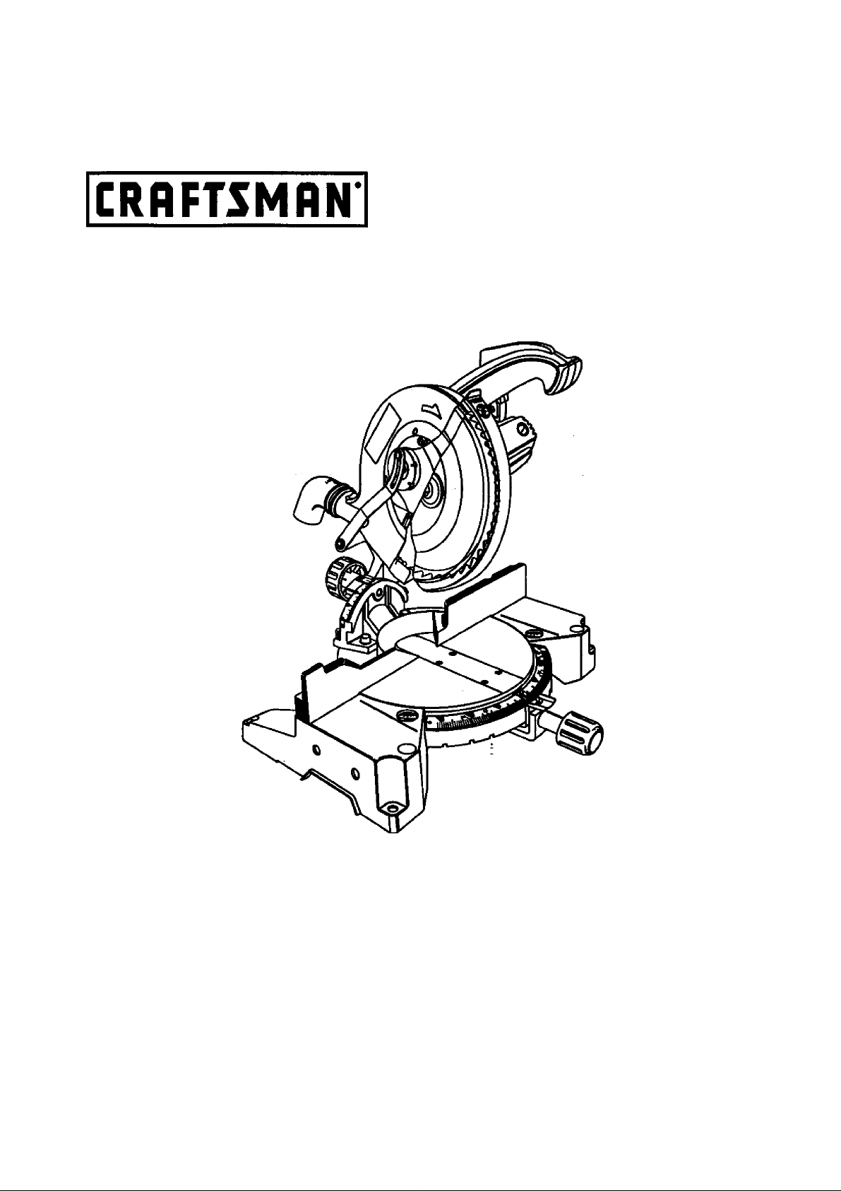
Owner's Manual
10 in. COMPOUND MITER SAW
Double Insulated
Model No.
315.212100
Save this manual for
future reference
A CAUTION: Read and follow
all Safety Rules and Operating
Instructions before first use of
this product.
Customer Help Line: 1-800-932-3188
Sears, Roebuck and Co., Hoffman Estates, IL 60179 USA
Visit the Craftsman web page:
972000-578
8-98
www.sears.com/craftsman -
• Safety
• Features
• Adjustments
• Operation
• Maintenance
• Parts List
NRTL/C
Page 2

TABLE OF CONTENTS
Table of Contents
Warranty and Introduction............................................................................................................................ 2
Rules For Safe Operation.............................................................................................................................. 3-6
Glossary........................................................................................................................................................... 6
Product Specifications and Unpacking.............................................................................................................. 7
Labels........................................................................................................................................................... 8
Loose Parts and Tools Needed......................................................................................................................... 9
Features............................................................................................................................................... 10-12
Adjustments.......................................................................................................................................... 13-19
Operation...................................................................................................................................................20-26
Maintenance......................................................................................................................................... 27-28
Exploded View and Repair Parts List...........................................................................................................30-37
Parts Ordering / Service................................................................................................................................. 38
.............................................
...............................................................................................
WARRANTY
FULL ONE YEAR WARRANTY
If this product fails due to a defect In material or workmanship within one year from the date of purchase,
Sears wilt repair it free of charge.
Contact a Sears Service Center for repair.
If this product is used for commercial or rental purposes, this wanwity applies only for 90 days from the date
of purchase.
This warranty gives you specific legal rights, and you may also have other rights which vary from state to state.
2
Sears, Roebuck and Co., DepL 81 TWA, Hoffman Estates, 1L 60179
INTRODUCTION
Your saw heis many features for making cutting
operations more pleasant and enjoyable. Safety,
performance and dependability have been given top
priority ih the design of this saw making it easy to
maintain and operate.
CAUTION: Carefuiiy read through this entire
owner's manual before using your new saw. Pay
close attention to the Rules For Safe Operation,
and aii Safety Alert Symbols including Danger,
Warning and Caution. If you use your saw
property and only for what it is intended, you will
enjoy years of safe, reliable service.
^ Look for this symbol to point out important safety precautions. It means attentionilt
Your safety is involved.
The operation of any power tool can result in foreign objects being thrown into your eyes,
which can result in severe eye damage. Before beginning power tool operation, always
wear safety goggles or safety glstsses with side shields and a full face shield when needed.
We recommend Wide Vision Safety Mask for use over eyeglasses or standard safety
glasses with side shields, available at Sears Retail Stores.:
Page 3

RULES FOR SAFE OPERATION
The purpose of safety symbols Is to attract your attention to possible dangers. The safety symbols, and
the explanations with them, deserve your careful attention and understanding. The safety warnings do
not by themselves eliminate any danger. The instructions or warnings they give are not substitutes for
proper accident prevention measures.
SYMBOL MEANING
^ SAFETY ALEFTT SYMBOL:
Indicates danger, warning or caution. May be used In conjunction with other symbc^ or pictographs.
A DANGER: Failure to obey a safety warning wiR result in serious injury to yourself or to others.
Always follow the safety precautions to reduce the risk of fire, electric shock and personal injury.
A WARNING: Failure to obey a safety warning can result in serious injury to yourself or to others.
Always follow the safety precautions to reduce the risk of fire, electric shock and personal injury.
CAUTION: Failure to obey a safety warning may result In property damage or personal injury to
yourself or to others. Always follow the safety precautions to r^uce the risk of fire, electric shock
and personal injury.
NOTE: Advises you of information or instmctions vital to the operation or maintenance of the equipment.
DOUBLE INSULATION
Double insulation is a concept in safety, in electric
power tools, which eliminates the need for the usual
three>wire grounded power cord. All exposed metal
parts are isolated from internal metal motor
components virith protecting insulation. Double
insulated tools do not need to be grounded.
A WARNING: Do not attempt to operate this tool
** until you have read thoroughly and understand
completely all instructions, safety rules, etc.
contained in this manual. Failure to comply can
result in accidents involving fire, electric shock,
or serious personal injury. Save owner's manual
and re\^ew frequently for continuing safe
operation, and instructing others who may use
this tool.
READ ALL INSTRUCTIONS
■ KNOW YOUR POWER TOOL. Read the owner's
manual carefully. Learn the saw's applications
and limitations as well as the specific potential
hazards related to this tool.
■ GUARD AGAINST ELECTRICAL SHOCK BY
PREVENTING BODY CONTACT WITH
GROUNDED SURFACES. For example; pipes,
radiators, ranges, refrigerator enclosures.
■ KEEP GUARDS IN PLACE and in good working
order.
■ REMOVE ADJUSTING KEYS AND
WRENCHES. Get in the habit of checking to see
that hex keys and adjusting wrenches are
removed from tool before turning on saw.
IMPORTANT
Servicing requires extreme care and knowledge of the
system and should be performed only by a qualified
service technician. For sen/ice we suggest you return
toe tool to your nearest Sears store for repair. Mways
use original factory replacement parts when servicing.
KEEP THE WORK AREA CLEAN. Cluttered work
areas and work benches invite accidents. DO
NOT leave tools or pieces of wood on the saw
while it is in operation.
DO NOT USE IN DANGEROUS ENVIRON
MENTS. Do r)ot use power tools near gasoline or
other flammable liquids, in damp or wet locations,
or expose them to rain. Keep the work area well
lit.
KEEP CHILDREN AND VISITORS AWAY. All
visitors should wear safety glasses and be kept a
safe distance from work area. Do not let visitors
contact tool or extension cord while operating.
MAKE WORKSHOP CHILD-PROOF with pad
locks and master switches, or by removing starter
keys.
DO NOT FORCE THE TOOL. It will do the job
better and safer at the rate for which it was
designed.
USE THE RIGHT TOOL. Do not force the tool or
attachment to do a job it was not designed for.
Don't use it for a purpose not intended.
Page 4

RULES FOR SAFE OPERATION (Continued)
■ USE THE PROPER EXTENSION CORD. Make
sure your extension cord is tn good condition.
When using an extension cord, be sure to use
one heavy enough to carry the current your
product wiii draw. An undersized cord wiii cause
a drop in iine voitage resulting in ioss of power
and overheating. A wire gage size (A.W.G.) of at
least 14 is recommended for an extension cord
25 feet or less in length. If in doubt, use the next
heavier gage. The smaller the gage number, the
heavier the cord.
■ INSPECT EXTENSION CORDS PERIODI
CALLY and replace if damaged.
■ DRESS PROPERLY. Do not wear loose clothing,
gloves, neckties, rings, bracelets, or other
jewelry. They can get caught and draw you into
moving parts. Rubber gloves and nor^lip foot
wear are recommended vt^en working outdoors.
Also wear protective hair covering to contsJn long
hair.
■ ALWAYS WEAR SAFETY GLASSES WITH
SIDE SHIELDS. Everyday eyeglasses have only
impact-resistant lenses; they are NOT safety
glasses.
■ PROTECT YOUR LUNGS. Wear a face or dust
mask if the cutting operation is dusty.
■ PROTECT YOUR HEARING. Wear hearing
protection during extended periods of operation.
■ SECURE WORK. Use clamps or a vise to hold
work when practical. Ifs safer than using your
hand and it frees both hands to operate tool.
■ DO NOT OVERREACH. Keep proper footing and
balance at all times.
■ MAINTAIN TOOLS WITH CARE. Keep tools
sharp and dean for better and safer perfor, mance. Follow instructions for lubricating and
= changing accessories.
■ DISCONNECT ALL TOOLS. When not in use,
before servidng, or when changing attadiments,
blades, bits, cutters, etc., all tools should be
disconnected.
■ AVOID ACCIDENTAL STARTING. Be sure
switch is off when plugging in.
■ USE RECOMMENDED ACCESSORIES. The
use of improper accessories may cause risk of
injury.
■ NEVER STAND ON TOOL. Serious injury could
occur if tiie tool is tipped or if the blade is unin
tentionally contacted.
■ CHECK DAMAGED PARTS. Before further use
of the tool, a guard or other part that is damaged
should be carefully checked to determine that it
will operate properly and perform its intended
function. Check for alignment of moving parts,
binding of moving parts, breakage of parts,
mounting and any other conditions that may
affect its operation. A guard or other part ttiat is
damaged must be properly repaired or replaced
by a qualified service technician at a Sears store
to avoid risk of personal injury.
NEVER LEAVE TOOL RUNNING UNAT
TENDED. TURN THE POWER OFF. Do not
leave tool until it comes to a complete stop.
RRMLY CLAMP OR BOLT your miter saw to a
workbench or table at approximately hip height.
USE ONLY CORRECT BLADES. Do not use
blades with incorrect size holes. Never use blade
washers or blade bolts that are defective or
incorrect. The maximum blade capacity of your
saw is 10 in.
KEEP BLADES CLEAN, SHARP AND WITH
SUFFICIENT SET. Sharp blades minimize
stalling and kickback.
DO NOT REMOVE THE SAWS BLADE ,
GUARDS. Never operate the saw with any guard
or cover removed. Make sure all guards are
operating properly before each use.
KEEP HANDS AWAY FROM CUTTING AREA.
Keep hands away from blades. Do not reach
underneath work or around or under the blade
while blade is rotating. Do not attempt to remove
cut material when blade is moving.
^ WARNING: Blade coasts after turn off.
DO NOT ABUSE CORD. Never yank cord to
disconnect it from receptacle. Keep cord from
heat oil, and sharp edges.
INSPECT TOOL CORDS PERIODICALLY and if
damaged, have repaired by a qualified service
technician at a Sears store. Stay constantly
aware of cord location and keep it well away
from tire rotating blade.
USE OUTDOOR EXTENSION CORDS. When
tool is used outdoors, use only extension cords
with approved ground connection that are
Intended for use outdoors and so marked.
DO NOT USE TOOL IF SWITCH DOES NOT
TURN IT ON AND OFF. Have defective switches
re(tiaced by a qualified service techniciem at a
Sears store.
KEEP TOOL DRY, CLEAN, AND FREE FROM
OIL AND GREASE. Always use a clean doth
when cleaning. Never use brake fluids, gasoline,
petroleum-based products, or any solvents to
clean tool.
Page 5

RULES FOR SAFE OPERATION (Continued)
■ ALWAYS SUPPORT LONG WORKPIECES to
minimize risk of blade pinctiing and Idckback.
Saw may siip, walk, or slide while cutting long or
heavy boards.
■ BEFORE MAKING A CUT, BE SURE ALL
ADJUSTMENTS ARE SECURE.
■ GUARD AGAINST KICKBACK. Kickback occurs
when the blade stalls rapidly and workpiece is
driven back towards the operator. It can pull your
hand into the blade resulting in serious personal
injury. Stay out of blade path and turn switch off
immediately if blade binds or stalls.
■ AVOID CUTTING NAILS. Inspect for and
remove all nails from lumber before cutting.
■ ALWAYS USE A CLAMP to secure the work
piece when possible.
■ NEVER TOUCH BLADE or other moving parte
during use.
■ NEVER START A TOOL WHEN THE BLADE IS
IN CONTACT WITH WORKPIECE. Allow motor
to come up to full speed before starting cut
■ MAKE SURE THE MITER TABLE AND SAW
ARM (BEVEL FUNCTION) ARE LOC№D IN
POSITION BEFORE OPERATING YOUR SAW.
Lock the miter teble by securely tightening the
miter lock handle. Lock the saw arm (bevel
function) by securely tightening the bevel lock
knob.
■ NEVER USE A LENGTH STOP ON THE FREE
SCRAP END OF A CLAMPED WORKPIECE.
NEVER hold onto or bind the free scrap end of
the workpiece in any operation. If a work damp
and length stop are used together, they must
both be installed on the same side of the saw
table to prevent the saw from catching №e loose
end and kicking up.
M NEVER cut more than one piece at a time. DO
NOT STACK more than one workpiece on the
saw table at a time.
■ NEVER PERFORM ANY OPERATION “FREE
HAND". Always place the workpiece to be cut on
the miter table and position it firmly against the
fence as a backstop. Always use №e fence.
■ NEVER hand hold a workpiece that is too small
to be clamped. Keep hands dear of the no hands
zone.
■ NEVER reach behind, under, or within three
inches of the biade and its cutting path with your
hands and fingers for any reason.
NEVER reach to pick up a workpiece, a piece of
scrap, or anything else that is in or near the
cutting path of the blade.
AVOID AWKWARD OPERATIONS AND HAND
POSITIONS where a sudden slip could cause
your hand to move into the blade. ALWAYS
m€d<e sure you have good balance. NEVER
operate your miter saw on the floor or in a
crouched position.
NEVER stand or have any part of your body in
line wite the path of the saw blade.
ALWAYS release the power switch and allow the
saw blade to stop rotating before raising it out of
the workpiece.
DO NOT TURN THE MOTOR SWITCH ON AND
OFF RAPIDLY. This could cause the saw blade
to loosen and could create a hazard. Should this
ever occur, stand dear and allow the saw Uade
to come to a complete stop. Disconnect your saw
from the power supply and securely retighten the
blade bolt.
REPLACEMENT PARTS. All repairs, whether
electrical or mechanical, should be made by
qualified sen/ice technician at a Sears store.
WARNING: When senricing use only identical
' Craftsman replacement parte. Use of any other
parts may create a hazard or cause product
damage.
NEVER USE IN AN EXPLOSIVE ATMO
SPHERE. Normal sparking of the motor could
ignite fumes.
NEVER leave the miter saw unattended while
connected to a power source.
POLARIZED PLUGS. To reduce the risk of
electric shock; this tool has a polarized plug (one
blade is wider than the other). This plug will № in
a polarized outlet only one way. If the plug does
not fit fully in the outlet, reverse the plug. If it still
does not fit, contact a qualified electrician to
instdt the proper outlet. Do not change the plug
in any way.
IF ANY PART OF THIS MITER SAW IS MISS
ING or should break, bend, or fail in any way, or
should any electriod component fail to perform
property, shut off tee power switch, remove the
miter saw plug from the power source and have
damaged, missing, or failed parts replaced
before resuming operation.
DO NOT OPERATE THIS TOOL WHILE UN
DER THE INFLUENCE OF DRUGS, ALCOHOL,
OR ANY MEDICATION.
Page 6

RULES FOR SAFE OPERATION (Continued)
■ ALWAYS STAY ALERT! Do not allow familiarity
(gained from frequent use of your saw) to cause
a careless mistake. ALWAYS REMEMBER that
a careless fraction of a second is sufficient to
inflict severe injury.
■ STAY ALERT AND EXERCISE CONTROL.
Watch what you are doing and use common
sense. Do not operate tool when you are Bred.
Do not rush.
SAVE THESE INSTRUCTIONS
GLOSSARY OFTERMS FOR WOODWORKING
Arbor
The shaft cm which a blade or cutting tool is mounted.
Bevel Cut
A cutting operation made with the blade at any angle
other than 90* to the miter table.
Crosscut
A oitting or shaping operation made across the grain
of the workpiece.
Compound Miter Cut
A compound miter cut is a cut made using a miter
angle and a bevel angle at the same time.
Freehand
Performing a cut without using a fence, miter gage,
fixture, work ctamp, or other proper device to keep the
workpiece from twisting or moving during the cut.
Gum
A sticky, sap based residue from wood products.
Miter Cut
A cutting operation made with the blade at any angle
other than 90* to the fence.
Resin
A sticky, sap base substance that has hardened.
Revolutions Per Minute (RPM)
The number of turns completed by a spinning object
in one minute.
Saw Blade Path
The area over, under, behind, or in front of the blade.
As it applies to the workpiece, that area which will be,
or has been, cut by the blade.
MAKE SURE THE WORK AREA HAS AMPLE
LIGHTING to see the work and that no obstnjc-
tions will interfere with safe operation BEFORE
performing any work using your saw.
ALWAYS TURN OFF SAW before disconnecting
it, to avoid accidental starting when re-connect
ing to power supply.
SAVE THESE INSTRUCTIONS. Refer to them
frequently and use to instruct otiier users. If you
loan someone this tool, loan them these instruc
tions also.
Set
The distance that the tip of the sawblade tooth is bent
(or set) outward horn the face of the blade.
Throw-Back ,
Throwing of a workpiece in a manner similar to a
kickback. Usually assodated with a cause other than
the kerf closing, such as a workpiece not being
against the fence, being dropped into the blade, or
being placed inadvertentiy in contact with the blade.
Through Sawing
Any cutting operation where the blade exterxls
completely through the thickness of the workpiece.
Workpiece
The Hern on which the cutting operation is being done.
The surfaces of a workpiece are commonly referred to
as faces, ends, and edges.
Zero Clearance Throat Plate
A plastic throat plate inserted in the miter table that
allows for blade clearance. Wheniyou make your first
cut with your compound miter saw, the saw blade cuts
a slot through the throat plate the exact width of the
blade. This provides for a zero clearance kerf that
minimizes workpiece tear-out.
No Hands Zone
The area between the marked lines on the left and
right side of the miter table base. This zone is
identified by no hands zone labels placed inside the
marked lines on the miter table base.
I
a
Page 7

PRODUCT SPECIFICATIONS
Blade Diameter
Blade Arbor
No Load Speed
Rating
Input
Net Weight
120 Volts, 60 Hz-AC Only
10 in.
5/8 in.
5000 RPM
15 Amperes
32 lbs.
UNPACKING
Your Compound Miter Saw has been shipped
compietely assembled except for the blade, miter lock
handle, and dust guide. .
WARNING: If any parts are missing, do not
operate this tool until the missing parts are
replaced. Failure to do so could result in possible
serious personal injury.
■ Remove all loose parts from the carton. Separate
and check with the list of loose parts. See Figure 2.
■ Remove the packing materials from around your
saw.
■ Carefully lift saw from the carton and place it on a
level work surface. Although small, this saw is
heavy. To avoid back injury, get help when
needed.
Cutting Capacity with Miter at 0°/Bevel 0°:
5-3/4 in. Wx 2-5/8 in. T
Maximum Cutting Capacity with Miter at 45°/Bevei 0°;
4-1/4 in. Wx 2-5/8 in. T
Maximum Cutting Capacity with Miter at 0°/Bevel 45°;
5-3/4 in. W x 1-7/8 in. T
Maximum Cutting Capacity with Miter at 45°/Bevel 45°:
4-1/4in. Wx 1-7/8in. T
■ Do not discard the packing materials until you
have carefully inspected the saw, identified alt
loose parts, and satisfactorily operated your new
saw.
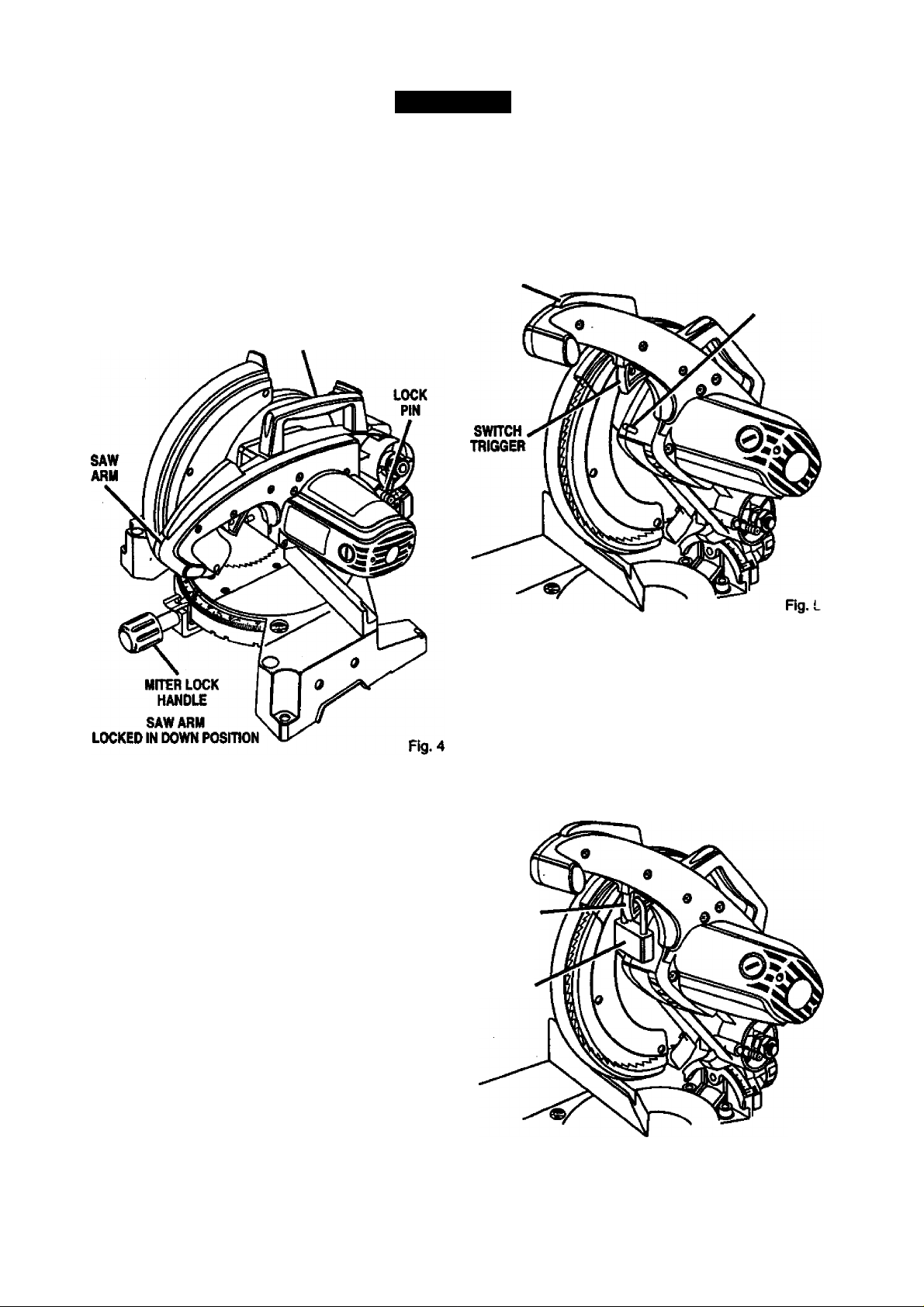
■ Your saw has been shipped with the saw arm
locked in the down position. To release saw arm,
push down on top of saw arm and pull out the lock
pin. See Figure 4. '
■ Lift the saw arm by the handle. Hand pressure
should remain on the saw arm to prevent sudden
rise upon release of the lock pin.
■ Examine all parts to make sure no breakage or
damage has occurred during shipping.
If any parts are damaged or missing, do not attempt to
plug in the power cord and turn the switch on until the
damaged or missing parts are obtained and are
installed correctly.
Page 8
The following labels are on the miter saw with toca
tions indicated.
Restore lower blade guard
and securely tighten screw
before use
Uft For Blade Change. See Owner's Manual.
G
DANGER: DO NOT REMOVE
ANY GUARD, USE OF SAW
WITHOUT THIS GUARD WILL
RESULT IN SERIOUS INJURY.
A WARNING / ADVERTENCIA
• For your safety, read ownen manual bulon optnllng
mitef saw.
• wear aya protaellon.
• Keep hands out of path of saw Mada.
• Do not operata saw wtthout guards In placa.
• Do not poifom any oparaUwi freehand.
• Nevar reach aroimd №a saw Uada.
• lUin off tool and wM for saw Made to atop before
moving woilipleee or changing satUnga.
• Disconnect the saw from the power source before
changing blade or servicing.
• Do not expose to rain or use in damp iriaces.
• Para su seguridad, lea el manual del usutulo antes
de usar la sierra ingletadwa.
10 inch Compound Miter Saw
DOUBLEMSUUra S,000RPN 12SV0US 611b MIMUr 15À
WARNING: when servkunu»
CRAFTSMAN REPLACEMENT PARTS.
MODEL 315.212100
ASseuauDM MEXICO
SEAHS,YKieSUCK AND CO.
USE (WILY IDENTICAL
36H.no.
Customer Help Line 1-S00-932-3188
Rg. 1
Page 9
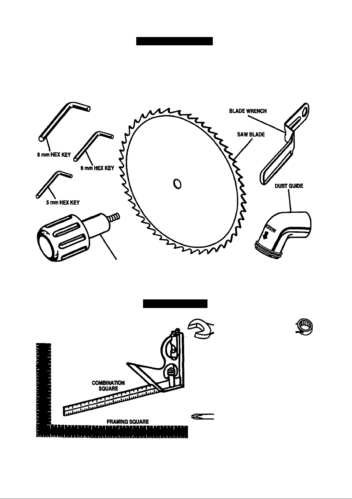
LOOSE PARTS LIST
The following items are included with your Compound Miter Saw:
Saw Blade • 10 in.
Miter Lock Handle
Dust Guide
Blade Wrench
5 mm Hex Key Wrench
6 mm Hex Key Wrench
8 mm Hex Key Wrench
Owner's Manual
MITER LOCK HANDLE
WARNING: The use of attachments or accessories not listed might be hazardous and could
** cause serious personal injury.
TOOLS NEEDED
The following tools (not included) are needed for
checking adjustments of your saw or for
installing the blade:
17 mm COMBINATION WRENCH
10 mm COMBINATION WRENCH
PHILUPS SCREWDRIVER
Fig. 2
Page 10
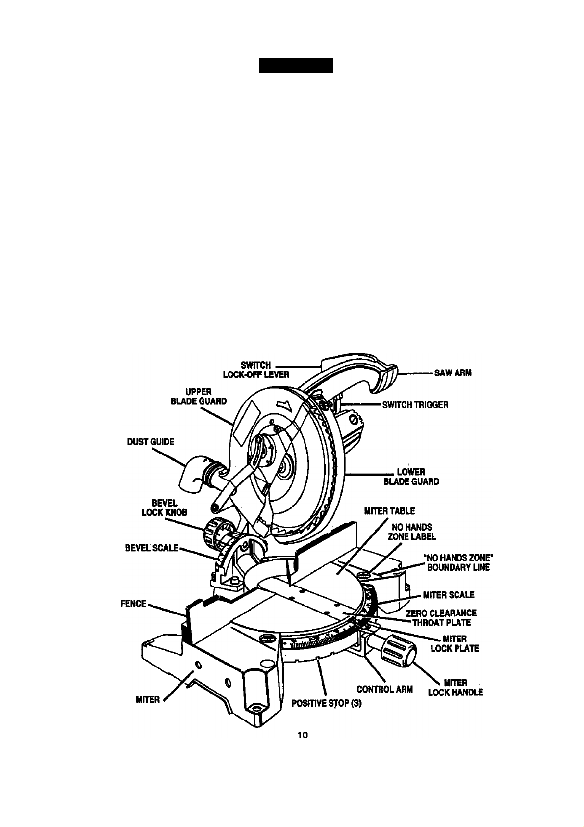
FEATURES
KNOW YOUR COMPOUND MITER
SAW
See Figure 3.
Before attempting to use your saw, familiatize yourself
with all operating features and safety requirements.
A WARNING; Do not allow familiarity with your
saw to make you careless. Remember that a
careless fraction of a second is sufficient to inflict
severe injury.
15 AMP MOTOR
Your saw has a powerful 15 amp motor with sufficient
power to handle tough cutting jobs. It is made eJI
ball bearings, and has externally accessible brushes
for ease of servicing.
10 In. BLADE
A10 in. saw blade is included with your compound
miter saw. It will cut materials up to 2-5№ in. thick or
5-3/4 in. wide, depending upon the thldmess of the
material and №e setting at ^ich the cut is being
made.
CUTTING CAPACITIES
When the miter angle (miter table) Is set at 0° and
the bevel angle Is set at 0°:
Your saw will cut materials up to a maximum of
5-3/4 in. wide X 2-5/8 in. thick.
When the miter angle (miter table) is set at 45° and
the bevel angle is set at 0°:
Your saw will cut materials up to a maximum of
4- 1/4 in. wide X 2-5/8 in. thick.
When the miter angle (miter table) Is set at 0° and
the bevel angle Is set at 45°:
Your saw will cut materials up to a maximum of
5- 3/4 in. wide X1-7/8 in. thick.
When the miter angle (miter table) Is set at 45° and
the bevel angle Is set at 45°:
Your saw will cut materials up to a maximum of
4*1/4 in. wide X 1-7/8 in. thick.
Fig.3
Page 11
FEATURES
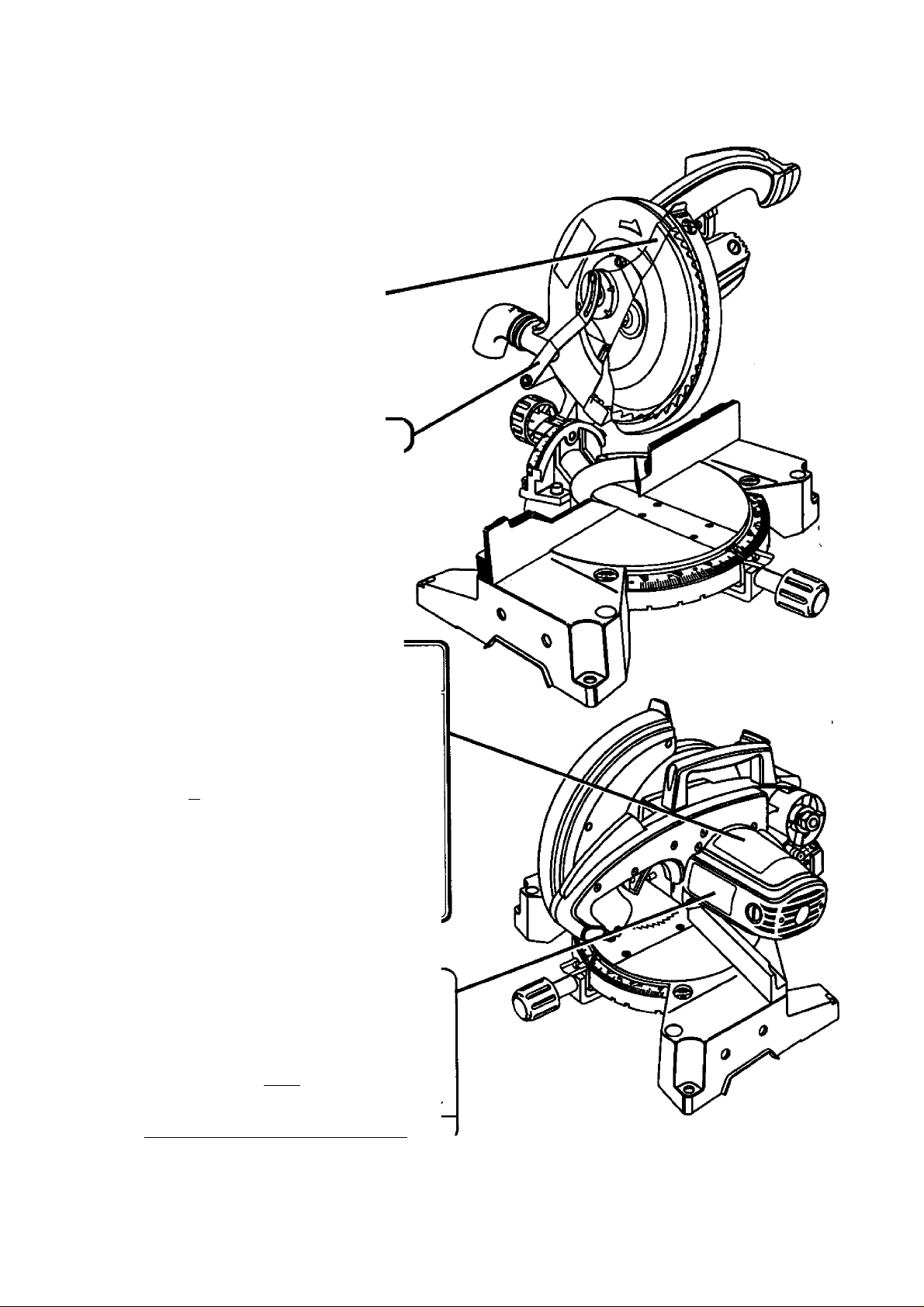
CARRYING HANDLE
See Figure 4.
For convenience when carrying or transporting your
miter saw from one place to another, a carrying
handle has been provided on top of the saw arm as
shown in figure 4. To transport, turn off and unplug
your saw, then lower the saw arm and lock it in the
down position. Lock saw amn by depressing the lock
pin.
CARRYING
HANDLE
SPINDLE LOCK BUTTON
See Figure 5.
A kindle lock button has been provided for locking
the spirtdie which stops the rotation of the blade in
your saw. Depress and hold the lock button while
installing, changing, or removing blade.
LOCK-OFF
LEVER
SPINDLE
LOCKBUnON
MITER LOCK HANDLE
See Figure 4.
Theiniter lock handle securely locks your saw at
desired miter angles.
LOCK-OFF LEVER
See Figure 5.
The switch trigger is equipped with a lock-off lever to
reduce the possibility of accidental starting. The tockoff lever must be pressed down with the palm of your
hand to turn saw on. Once the saw is on, the lock-off
lever can be released. The spring loaded lever wilt
spring back into the lock-off position when the switch
trigger is released.
TRIGGER LOCK
See Figure 6.
To prevent unauthorized use of your compound miter
saw, we suggest that you disconnect it from the power
supply and lock №e switch in the off position. To lock
the switch, install a padlock through the hole in the
switch trigger. A lock with a shackle up to 13/64 in.
diameter may be used. When the lock is installed and
locked, the switch is inoperable. Store the padlock key
in another location.
SWITCH
TRIGGER
PADLOCK
11
Fig. 6
Page 12

FEATURES
POSITIVE STOPS ON MITER TABLE
Positive stops have been provided at 0°, 22-1/2° and
45°. The 22-1/2° and 45° positive stops have been
provided on both the left and right side of the miter
table.
BEVEL LOCK KNOB
The bevel lock knob securely locks your compound
miter saw at desired bevel angles. Positive stop
adjustment screws have been provided on each side
of the saw arm. These adjustment screws are for
maJ<ing fine adjustments at 0° and 45°. See pages 18
and 19.
ELECTRIC BRAKE
An electric brake has been provided to quickly stop
blade rotabon after the switch is released.
FENCE
The fence on your compound miter saw has been
provided to hold your workpiece securely against
when making all cuts.
SELF-RETRACTING LOWER BLADE
GUARD
The tower blade guard is made of shock-resistant,
see-through plastic that provides protection from each
side of tile blade. It retracts over the upper blade
guard as the saw is lowered into the workpiece.
MOUNTING HOLES
See Figure 7.
Your compound miter saw should be permanently
mounted to a firm supporting surface such as work
bench. Four 7/16 in. bolt holes have been provided in
the saw base for this purpose. Each of the four
mounting holes should be bolted securely using 7/16
in. machine bolts, lock washers, and hex nuts (not
included). Bolts should be of sufficient length to
accommodate the^saw base, lock washers, hex nuts,
and the thickness of the workbench.
Tighten all four bolts securely.
The hole pattern for an 18 in. x 24 in. workbench is
shown in Figure 7. Carefully check the workbench
after mounting to make sure that no movement can
occur during use. If any tipping, sliding, or walking is
noted, secure the workbench to the floor before
operating.
---------------------------- 2T
32or
*
ir
ID inr
y-mrakWAi
/ .A,
33nr
----------------------------
-----------------------------
24“
-------^------------------
-313f3r-
S-
-t
Fig. 7
ELECTRICAL CONNECTION
Your saw has a precision built electric motor. It should
be connected to a power supply that Is 120 volts,
60 Hz, AC only (normal household current). Do not
operate this tool on direct current (DC). A substantial
voltage drop will cause a loss of power and the motor
will overheat. If your tool does not operate when
plugged into an outlet, double-check the power
supply.
A WARNING: The operation of any saw can
result in foreign objects being thrown into your
eyes, which can result in severe eye damage.
Before starting power tool operation, always
wear safety goggles or safety glasses with side'
shields and a full face shield when needed. We
recommend wide vision safety mask for use over
eyeglasses or standard safety glasses with side
shields.
A^ WARNING: Do not attempt to modify this tool or
create accessories not recommended for use
with this toot. Any such alteration or modification
is misuse and could result in a hazardous
condition leading to possible serious personal
injury.
A WARNING: Always make sure your compound
miter saw is securely mounted to a workbench or
an approved workstand. Failure to do so could
result in an accident resulting in possible serious
personal injury.
12
Page 13

ADJUSTMENTS
A WARNING: To prevent accidental starting that
could cause possible serious personal injury,
assemble all parts to your saw before connecting
it to power supply. Saw should never be
connected to power supply when you are
assembling parts, making adjustments, installing
or removing blades, or when not in use.
As mentioned previously your saw has been factory
assembled and adjusted. The miter lock handle, dust
guide, and blade are the only parts that have to be
installed.
MITER LOCK HANDLE
See Figure 8.
To install the miter lock handle, place the threaded
stud on the end of the miter lock handle into the
threaded hole in the control arm. Turn clockwise to
tighten.
TO INSTALL BLADE
See Figures 10, 11, and 12.
WARNING: A 10 in. blade Is the maximum
blade capacity of your saw. Never use a blade
that is too thick to allow outer blade washer to
engage with the flats on the spindle. Larger
blades will come in contact with the blade
guards, while thicker blades will prevent the
blade screw from securing the blade on the
spindle. Either of these situations could result in
a serious accident and can cause serious
personal injury.
■ Unplug your saw.
WARNING; Failure to unplug your saw could
result in accidental starting causing possible
serious personal injury.
■ Push down on the saw arm and pull out the lock
pin to release saw arm. Raise saw arm to its full
raised position. Be cautious, saw arm is spring
loaded to raise.
■ Loosen the phillips screw on the blade bolt
cover until blade bolt cover can be raised.
See Figure 10 and 11.
■ Gently raise the lower blade guard bracket,
releasing lower blade guard from notch so that
lower blade guard and blade bolt cover can be
rotated up and back to expose the blade bolt See
Figures 10 and 11.
DUST GUIDE
See Figure 9.
To install the dust guide, place the end marked
INSERT over the exhaust port in the upper blade
guard. Turn the guide so that №e open end Is facing
down or toward the rear of the saw.
Page 14

ADJUSTMENTS
LOWER
BLADE GUARD
BLADE
BOLT COVER
BUDEBOLT Fig. 11
PHILUPS
SCREW
FUT(S)
ON SPINDLE
INNER BLADE
WASHER WITH
DOUBLE "D* FLATS
»OUTER BLADE WASHER
WITH DOUBLE "D* FUTS
Depress the spindle lock button and rotate die
blade bolt until the spindle locks. See Figure 12.
Using the blade wrench provided, loosen and
remove the blade bolt.
Note: The blade bolt has left hand threads. Turn
blade bolt clockwise to loosen.
Remove outer blade washer. Do not remove
inner blade washer.
■ Wipe a drop of oil onto inner blade washer and
outer blade washer where they contact the blade.
A WARNING: If inner blade washer has been
removed, replace it before placing blade on
spindle. Failure to do so could cause an accident
since blade will not tighten properly.
■ Fit saw blade inside lower blade guard and onto
spindle. The blade teeth point downward at the
front of saw as shown in figure 11.
iV CAUTION: Always install the blade wth the
blade teeth and the arrow printed on the side of
the blade pointing down at the front of the saw.
The direction of blade rotation is also stamped
with an arrow on the upper blade guard.
■ Replace outer blade washer. The double ''D* flats
on tite blade washers align with the flats on the
spindle.
■ Depress spindle lock button and replace blade
bolt. <
Note: The blade bolt has left hand threads. Turrt
blade bolt counterclockwise to tighten.
■ Tighten blade bolt securely.
■ Remove the blade wrench and store it in a safe
place for future use.
■ Replace the lower blade guard and blade bolt
cover.
■ Retighten phillips screw securing blade bolt cover.
Tighten screw securely. See Figure 11.
SPINDLE
LOCK
BUnON
Fig. 12 ^
14
A WARNING: To prevent damage to the spindle
** lock, always allow motor to come to a complete
stop before engaging spindle lock. Make sure the
spindle lock button is not engaged before
reconnecting saw into power source.
Your compound miter saw has been adjusted at the
factory for making very accurate cuts. However, some
of the components might have been jarred out of
alignment during shipping. Also, over a period of time,
readjustment will probably become necessary due to
wear. After unpacking your saw, check the following
adjustments before you begin using saw. Make any
readjustments that are necessary and periodically
check the parts alignment to make sure that your saw
is cutting accurately.
WARNING: Your saw should never be
connected to power supply when you are
assembling parts, making adjustments, installing
or removing blades, or when not in use.
Disconnecting your saw will prevent accidental'
starting that could cause serious injury.
Page 15

ADJUSTMENTS
Note: Many of the illustrations in this manual show
only portions of your compound miter saw. This is
intentional so that we can clearly show points being
made in the illustrations. Never operate your saw
without all guards securely in place and in good
operating condition.
CUtTINQ A SLOT IN THE ZERO
CLEARANCE THROAT PLATE
In order to use your compound miter saw, you must
cut a slot through the zero clearance throat plate to
allow for blade clearance. To cut the slot, set your
saw at 0 degrees miter, turn saw on and allow the
blade to reach full speed, then carefully make a
straight cut as far as it will go through the throat plate.
Turn your saw off and allow the blade to come to a
complete stop before raising the saw ami.
Next, adjust bie bevel angle to 45 degrees, turn your
saw on and allow the blade to reach full speed, then
carefully make another cut through the zero clearance
throat plate. The throat plate will then be wide enough
to allow the blade to pass through it at any angle from
0 to 45 degrees.
SQUARING THE MITER TABLE
TO THE FENCE
See Figures 13 -16.
■ Unplug your saw.
FRAMING
SQUARE
MITER
LOCK HANDLE
VIEW OF MITER TABLE SQUARE WITH FENCE
AND COTRECTLY ADJUSTED
Fig. 13
A WARNING; Failure to unplug your saw could
result in accidental starting causing possible
serious personal injury.
■ Push down on the saw arm and pull out the lock
pin to release the saw arm.
■ Raise saw arm to its full raised position.
■ Loosen the miter lock handle approximately one-
haOf turn.
■ Depress theimiter lock plate and rotate the miter
table until the pointer on tfie control arm is posi
tioned at 0°.
■ Release the miter lock plate and securely tighten
the miter lock handle.
■ Lay a framing square flat on the miter table. Place
one leg of the square against the fence. Place the
other leg of the square beside the zero clearance
throat plate in the miter table. The edge of the
square and the zero clearance throat plate in
the miter table should be parallel as shown in
figure 13.
■ If the edge of the framing square and the zero
clearance throat plate in the miter table are not
parallel as shown in figures 14 and 15, adjust
ments are nmded.
15
FRAMING
SQUARE
VIEW OF MITER TABLE NOT SQUARE WITH
FENCE, ADJUSTMENTS ARE REQUIRED
VIEW OF MITER TABLE NOT SQUARE WITH
FENCE, ADJUSTMENTS ARE REQUIRED
ZERO CLEARANCE
THROAT PUTE
MITER TABLE
ZERO CLEARANCE
THROAT PUTE
Fig. 14
Fig. 15
Page 16

ADJUSTMENTS
Using an 6 mm key, loosen the socket head
screws securing the fence. See Figure 16. Adjust
the fence left or right until the framing square and
zero clearance throat plate are parallel.
Retighten the screws securely and recheck the
fence-to-table alignment.
SQUARING THE SAW BLADE TO THE
FENCE
See Figures 17-20.
■ Unplug your saw.
FENCE
FENCE
MfTER
TABLE
VIEW OF BLADE
SQUARE WTTH FENCE
MITER
LOCK HANDLE
Fig. 17
WARNING; Failure to unplug your saw could
result in accidental starting causing possible
serious personal injury.
■ Pull the saw arm alt the way down and engage
the lock pin to hold the saw arm In transport
position.
■ Loosen the miter lock handle approximately
one-half turn.
■ Depress the miter lock plate and rotate the miter
table until the pointer on the control arm is
positioned at 0°.
■ Release the miter lock plate and securely tighten
the miter lock handle.
■ Lay a framing square flat on the miter table. Place
one leg of the square against the fence. Slide the
other leg of the square against the flat part of saw
blade.
Note; Make sure that the square contacts the flat
part of the saw blade, not the blade teeth.
MITER FRAMING
TABLE SQUARE
VIEW OF BLADE NOT SQUARE WITH
FENCE, ADJUSTMENTS ARE REQUIRED
MITER FRAMING
TABLE SQUARE
VIEW OF BLADE NOT SQUARE WITH
FENCE, ADJUSTMENTS ARE REQUIRED
Fig. 18
Fig. 19
16
Page 17

ADJUSTMENTS
The edge of the square and the saw blade should
be parallel as shown in figure 17.
If the front or back edge of the saw blade angles
away from the square as shown in figures 18 and
19, adjustments are needed.
Using the 8 mm hex key provided, loosen the
socket head screws that secure the mounting
bracket to the miter table. See Figure 20.
Loosen bevel lock Imob and set saw arm at 0”
bevel (blade set 90“ to miter t£*le). Tighten bevel
lock knob.
Place a combination square against the miter
table and the fiat part of saw blade.
Note: Make sure that the square contacts the flat
part of the saw blade, not the blade teeth.
Rotate the blade by hand and check the blade-totable alignment at several points.
The edge of the square and the saw blade should
be parallel as shown in figure 21.
FENCE
COMBINATION
UfTER SQUARE
TABLE
LOCK HANDLE
CORRECT VIEW OF BLADE
SQUARE WITH MITER TABLE
MITER
Fig. 21
■ Retighten the screws securely and recheck the
blade-to-fence alignment.
SQUARING THE BLADE TO THE
MITER TABLE
See Figures 21-24.
■ Unplug your saw.
A WARNING: Failure to unplug your saw could
resuK in accidental starting causing possible
serious personal injury.
■ Pull the saw arm all the way down and engage
the lock pin to hold the saw arm in transport
position.
■ Loosen the miter lock handle approximately one-
half turn.
■ Depress №e miter lock plate and rotate the miter
table until the pointer on the control arm is posi
tioned at 0°.
■' Relefise the miter lock plate and securely tighten
the miter lock handle.
If the top or bottom of the saw blade angles away
from the square as shown in figures 22 and 23,
adjustments are needed.
FENCE
MITER
TABLE
VIEW OF BLADE NOT SQUARE WITH MITER
TABLE, ADJUSTMENTS ARE REQUIRED
COMBINATION
SQUARE
Rg.22
17
Page 18

ADJUSTMENTS
FENCE
MrrER
TABLE
VIEW OF BLADE NOT SQUARE WITH MITER
TABLE, ADJUSTMENTS ARE REQUIRED
SQUARE
Using a 10 mm wrench or adjustable wrench,
loosen №e lod< nut securing positive stop adjust
ment screw. Aiso ioosen bevei lock knob.
Adjust positive stop adjustment screw to bring
saw biade into aiignment with Uie square. See
Figure 24.
Fig. 23
POSmVESTOP
ADJUSTMENT
SCREW FOR
45° ANGLES
PIVOT ADJUSTMENTS
Note: These adjustments were made at ttie factory
and normaily do not require readjustment.
TRAVEL PIVOT ADJUSTMENT
■ The saw arm should rise completely to the up
position by itseif.
■ if the saw arm does not raise by itself or if there is
play in the pivot joints, have saw repaired by a
qualified service technician at your nearest Seeurs
store to avoid risk of personal injury.
BEVEL PIVOT ADJUSTMENT
■ Your compound miter saw should bevel easily by
loosening the bevel lock knob and tilting the saw
arm to the left.
M If movement is tight or if there is play in the pivot,
have saw repaired by a qualified service ter^nician at your nearest Sears store to avoid risk of
personal injury.
DEPTH STOP
The depth stop limits the blade's downward travel. It,
allows the blade to go below the miter table enough to
maintain full cutting capacities. The depth stop posi
tions the blade 1/4 in. from the miter table support.
Note: The miter tabie support is located inside miter
table.
The depth stop is factory set to provide maximum
cutting capacity for the 10 in. saw blade provided with
your saw. Therefore, the saw blade provided should
never need adjustments.
However, when the diameter of the blade has been '
reduced due to sharpening, it may be necessary to
adjust the depth stop to provide maximum cutting
capacity. Also, when a new blade is installed. It is
necessary to check the clearance of the blade to the
miter table support before starting the saw. Make
adjustments if needed.
DEPTH STOP ADJUSTMENTS
See Figure 25.
■ Unplug your saw.
f
■ Retighten bevei iock knob. Next, retighten iock nut
securing the positive stop adjustment screw.
Recheck blade-to-table aiignment.
Note: The above procedure can be used to check
biade squareness of the saw biade to the miter
tabie at both 0° and 45° angies.
Your saw has three scale indicators, two on either
side of the bevei scaie and one on the miter scaie.
After squaring adjustments have been made, it may
be necessary to loosen the indicators screws and
reset them to zero.
A WARNING: Failure to unplug your saw could
result in accidental starting causing possible
serious personal injury.
■ To adjust the depth stop use a 17 mm wrench or
adjustable wrench and loosen the hex nut at the
rear of the miter saw arm.
■ Use the 5 mm hex key wrench provided to adjust
the depth stop adjustment screw. The saw blade
is lowered by turning the screw counter-clockwise
and raised by turning the screw clockwise.
18
Page 19

ADJUSTMENTS
DEPTH STOP
ADJUSTMENT
SCREW
BEVEL
LOCK KNOB
MITER
TABLE
POSITIVE
STOP ADJUSTMENT
SCREW FOR 0° ANGUS
LOCKNUT(S)
Fig. 25
■ Lower the blade Into the zero clearance throat
plate of the miter table. Check blade clearance
and maximum cutting distance (distance from
fence where blade enters) to frcmt of miter table
slot.
■ Readjust if necessary.
A WARNING: Do not start your compound miter
saw without checking for interference between
the blade and the miter table support. Damage
could result to the blade If it strikes the miter
table support during operation of №e saw.
■ Tighten the hex nut with a 17 mm wrench or
adjustable wrench.
■ To prevent the depth stop adjustment screw from
turning while tightenin^the hex nut, carefully hold
it with the hex key wrench while tightening the
hex nut.
APPLICATIONS
(Use only for the purposes listed below)
■ Cross cutting wood and plastic.
■ Cross cutting miters, joints, etc. for picture frames,
moldings, door casings, and fine joinery.
Note: The 104 tooth crosscut blade provided is fine
for most wood cutting operations, but for fine joinery
cuts or cutting plastic, use one of the accessory
blades available from your nearest Sears store.
WARNING: Before starting any cutting
operation, clamp or bolt your compound miter
saw to a workbench. Never operate your miter
saw on the floor or in a crouched position.
Failure to heed this warning can result in serious
personal injury.
CUTTING WITH YOUR COMPOUND
MITER SAW
WARNING: When using a work clamp or
Oclamp to secure your workpiece, clamp
workpiece on one ¿de of the blade only. The
workpiece must remain free on one side of the
blade to prevent the blade from binding in
workpiece. The workpiece binding the blade will
cause motor stalling and kickback. This situation
could cause an acddent resulting in possible
serious personal injury.
CROSSCUTTING
See Figure 26.
A crosscut is made by cutting across the grain of №e
workpiece. A straight crosscut is made with the miter
table set at the zero degree position. Miter crosscuts
are made with the miter table set at some angle other
than zero.
TO CROSSCUT WITH YOUR MITER
SAW:
■ Pull out the lock pin and lift saw arm to its full
height.
■ Loosen the miter lock handle. Rotate tiie miter
lock handle approximately one-haK turn to the left
to loosen.
■ Press the miter lock plate down with your thumb
and hold.
■ Rotate the control arm until the pointer aligns with
the desired angle on the miter scale.
■ Release the miter lock plate.
Note: You can quickly locate 0°, 22-1/2*’ left or
right, smd 45* left or right by releasing the lock
plate as you rotate the control arm. The lock plate
will seat itself in one of the positive stop notches,
located in the miter table frame.
■ Tighten the miter lock handle securely.
A WARNING: To avoid serious personal injury,
always tighten the miter lock handle securely
before making a cut. Failure to do so could result
in movement of the control arm or miter table
while making a cut.
19
Page 20

OPERATION
■ Slowly lower the blade into and through the
■ Release the switch trigger emd allow the saw
BEVEL CUT
See Figures 27 and 28.
A bevel cut is made by cutting across the grain of the
workpiece with the blade angled to the workpiece. A
straight bevel cut is made with the miter table set at
the zero degree position and the blade set at an angle
between 0* and 45®.
workpiece. See Figure 26.
blade to stop rotating before raising the blade out
of workpiece. Wait until the electric brake stops
blade from turning before removing the workpiece
from the miter table.
OCLAMP Rg.26
Place the workpiece fiat on the miter table with
one edge securely against the fence, if the board
is warped, place the convex side against the
fence, if the concave edge of a board is placed
against the fence, the board could collapse on the
blade at the end of the cut, jamming the blade.
See Figures 33 and 34.
When cutting tong pieces of lumber or molding,
support the opposite end of the stock with a roller
stand or with a work surface level with the saw
table.
Align cutting line on the workpiece with the edge
of saw blade.
Grasp the stock firmly with one hand ^d secure
it against the fence. Use the optional work clamp
or a C-clamp to secure the workpiece when
possible. See Figure 26.
k WARNING: To avoid serious personal injury,
^ keep your hands outside the no hands zone; at
le£№t 3 in. from blade. Never perform any cutting
operation freehand (without holding workpiece
against the fence). The blade could grab the
workpiece if it slips or twists.
Before turning on tiie saw, perform a dry run of the
cutting operation just to make sure that no
problems will occur when the cut is made.
Grasp the saw handle firmly, press the lock-off tab
down, then squeeze the switch trigger.'Allow
several seconds for the blade to reach maximum
speed.
LEFTSIDE
LEFT
INDICATOR
POINT
SCALE
MOUNTING BRACI^
RIGHT SIDE
INDICATOR
SCALE
TO BEVEL CUT WITH YOUR MITER
SAW:
■ Pull out the lock pin and lift saw ann to its full
height.
■ Loosen the miter lock handle. Rotate the miter
lock handle approximately one-half turn to the left
to loosen.
■ Press the miter lock plate down with your thumb
and hold.
■ Rotate the control arm until the pointer aligns with
zero on the miter scale.
■ Release the miter lock plate.
Note: You can quickly locate zero by releasing
the lock plate eis you rotate the control arm. The
lock plate will seat itself in one of the built-in
positive stop notches, located in the miter table
frame.
■ Tighten the miter lock handle securely.
WARNING: To avoid serious personal injury,
always tighten the miter lock handle securely
before making a cut. Failure to do so could result
in movement of the control arm or miter table
while making a cut.
20
RIGHT
POINT
Fig. 27
Page 21

OPERATION
BEVEL CUT
X-CLAMP
Loosen the bevel lock knob and move the saw
arm to the left to the desired bevel angle.
Bevel angles c€in be set from 0® to 45®.
For your convenience there is a doubie scale
located on the mounting bracket. See Figure 27. If
one side becomes difficult to read as you move
the saw arm to the left, simply refer to the other
side. Align the indicator point for the side you
choose with the desired angie.
Once the saw arm has been set at the desired
angle, securely tighten the bevel lock knob.
Place the workpiece flat on tiie miter table with
one edge securely against the fence. If the board
is warped, place the convex side against the
fence. If the concave edge of a board is placed
against the fence, the board could collapse on the
blade at the end of the cut, jamming the blade.
See Figures 33 and 34.
When cutting long pieces of lumber or molding,
support the opposite end of the stock with a roller
stand or with a work surface level with the saw
table.
Align the cutting line on the workpiece with the
edge of saw blade.
Grasp the stock firmly with one hand and secure it
against the fence. Use the optional work clamp or
a C-clamp to secure the workpiece when pos
sible. See Figure 28.
Fig. 28
A WARNING: To avoid seriCHJS personal injury,
keep your hands outside the no hands zone; at
least 3 in. from blade. Never perform any cutting
operation freehand (without holding workpiece
against the fence). The blade could grab the
workpiece if it slips or twists.
■ Before turning on the saw, perform a dry run of
the cutting operation just to make sure №at no
problems will occur when the cut is made.
■ Grasp the saw handle firmly, press the lock-off te^
down, then squeeze the switch bigger. Allow
several seconds for the blade to reach maximum
speed.
■ Slowly lower the blade into and through the
workpiece. See Figure 28.
■ Release the switch trigger and allow the saw
blade to stop rotating before raising the blade out
of workpiece. Wait until the electric brake stof»
blade from turning before removing the workpiece
from miter table.
COMPOUND MITER CUT <
A compound miter cut is a cut made using a miter "
angle and a bevel angle at the same time. This type of
cut is used to make picture frames, cut molding, make
boxes with sloping sides, and for certain roof framing
cuts.
To make this type of cut the control arm on the miter
table must be rotated to the correct angle and the saw
arm must be tilted to the correct bevel angle. Care
should always be taken when making compound miter
setups due to the interaction of the two angle settings.
Adjustments of miter and bevel settings are interde
pendent with one another. Each time you adjust the
miter setting you change the effect of the bevel
setting. Also, each time you adjust the bevel setting
you ch^ge the effect of the miter setting.
It may take several settings to obtain the desired cut.
The first angle setting should be checked after setting
the second angle, since adjusting the second angle
affects the first.
Once the two correct settings for a particular cut have
been obtained, always make a test cut in scrap
material before making a finish cut in good material.
21
Page 22

OPERATION
TO MAKE A COMPOUND CUT WITH
YOUR MITER SAW:
■ Pull out the lock pin and lift saw arm to its full
height.
■ Loosen the miter lock handle. Rotate the miter lock
handle approximately one-half turn to the left to
loosen.
■ Press the miter lock plate down with your thumb
and hold.
■ Rotate the control arm until the pointer aligns with
the desired angle on the miter scale.
■ Release the miter lock plate.
Note: You can quickly locate O', 22-1/2' left or
right, and 45* left or right by releasing the miter
lock plate as you rotate the control arm. The miter
lock plate will seat itself in one of the positive stop
notches, located in miter table frame.
■ Tighten the miter lock handle securely.
^ WARNING: To avoid serious personal injury,
always tighten the miter lock handle securely
before making a cut. Failure to do so could result
in movement of the control arm or miter table
while making a cut.
■ Recheck miter angle setting. Make a test cut in
scrap material.
■ Place the workpiece flat on the miter table wth
one edge securely against the fence. If the board
is warped, place the convex side against the
fence. If the concave edge of a board could
collapse on the blade at the end of the cut,
jamming the blade. See Figures 33 and 34,
■ When cutting long pieces of lumber or molding,
support the opposite end of the stock wi№ a roller
stand or with a work surface level with the saw
table.
■ Align the cutting line on the workpiece with the
edge of saw blade.
■ Grasp the stock firmly with one hand and secure it
against the fence. Use the optional work clamp or
a C-damp to secure the workpiece when possible.
See Figure 29.
WARNING: To avoid serious personal injury,
always keep your hands outside the no hands
zone; at least 3 in. from blade. Never perform aiiy
cutting operation freehand (without holding
workpiece against the fence). The blade could
grab the workpiece if it slips or twists.
■ Loosen the bevel lock knob and move the saw arm
to the left to the desired bevel angle.
■ Bevel angles can be set from O' to 45'.
■ For your convenience there is a double scale
located on the mounting bracket. See Figure 27. If
one side becomes difficult to read as you move the
saw arm to the left, simply refer to the other side.
Align the indicator point for the side you choose
with the desired angle.
■ Once the saw arm has been set at the desired
angle, securely tighten the bevel lock knob.
^C-CLAMP
COMPOUND
MfTER CUT
Fig. 29
22
Page 23

OPERATION
■ Before turning on the saw, perform a dry run of the
cutting operation just to make sure that no problems
will occur when the cut is made.
■ Grasp the saw handie firmly, press the lock-off tab
down, then squeeze the switch trigger. Allow sev
eral seconds forthe blade to reach maximum speed.
■ Slowly lower the blade Into and through the
workpiece. See Figures 29 and 30.
■ Release the switch trigger and allow the saw blade
to stop rotating before raising the blade out of
vrarkpiece. Wait until the electric brake stops blade
from turning before removing the workpiece from
miter table.
SUPPORT LONG WORKPIECES
See Figure 31.
Long workpieces need extra supports. Supports
should be placed along the workpiece so it does not
sag. The support should let the workpiece lay flat on
the base of the saw and work table during the cutting
operation. Use the optional work clamp or a Oclamp
to secure the workpiece.
WARNING: To avoid serious personal injury,
always keep your hands outside the no hands
zone; at least 3 in. from blade. Never perform
any cutting operation freehand (without holding
workpiece against the fence). The blade could
grab the workpiece if it slips or twists.
LONG WORKPIECE
WORKPIECE SUPPOFTTS
Fig. 31
23
Page 24

OPERATION
CUTTING COMPOUND MITERS
To aid in making the correct settings, the compound angle setting chart below has been provided. Since com
pound cuts are the most difficult to accurately obtain, trial cuts should be made in scrap material, and much
thought and planning made, prior to making your required cut.
PITCH
OFSDE
0°
5°
10*
15°
20°
25°
30°
35°
40°
45°
50°
55°
60°
65°
70°
75°
80°
85°
90°
4
M- 45.00°
B- 0.00°
M- 44.89°
B- 3.53°
M- 44.56°
B- 7.05°
M- 44.01°
B-10.55°
M- 43.22°
B-14.00°
M-42.19°
B-17.39°
M- 40.89°
B- 20.70°
M-39.32°
B- 23.93°
M- 37.45°
B- 27.03°
M- 35.26°
B- 30.00°
M- 32.73°
B- 32.80°
M- 29.84°
B- 35.40°
M- 26.57°
B- 37.76°
M-22.91°
B- 39.86°
M-18.88°
B- 41.64°
M-14.51°
B- 43.08°
M- 9.85°
B-44.14°
M- 4.98°
B- 44.78°
M- 0.00°
B- 45.00°
5
M- 36.00°
B- 0.00°
M- 35.90°
B- 2.94°
M- 35.58°
B- 5.86°
M- 35.06°
B- 8.75°
M- 34.32°
B-11.60°
M- 33.36°
B-14.38°
M-32.18°
B- 17.09°
M- 30.76°
B-19.70°
M- 29.10°
B- 22.20°
M-27.19°
B- 24.56°
M- 25.03°
B-26.76°
M- 22.62°
B- 28.78°
M-19.96°
B- 30.60°
M-17.07°
B-32.19°
M-13.95°
B- 33.53°
M-10.65°
B- 34.59°
M- 7.19°
B- 35.37°
M- 3.62°
B- 35.84°
M- 0.00°
B- 36.00°
nUMDCn Ur
6
M- 30.00°
B- 0.00°
M-29.91°
B- 2.50°
M- 29.62°
B- 4.98°
M- 29.15°
B- 7.44°
M- 28.48°
B- 9.85°
M- 27.62°
B-12.20°
M- 26.57°
B-14.48°
M- 25.31°
B-16.67°
M- 23.86°
B-18.75°
M-22.21°
B- 20.70°
M- 20.36°
B- 22.52°
M-18.32°
B-24.18°
M-16.10°
B- 25.66°
M-13.71°
B^ 26.95°
M-11,17°
B- 28.02°
M- 8.50°
B- 28.88°
M- 5.73°
B- 29.50°
M- 2.88°
B- 29.87°
M- 0.00°
B- 30.00°
7 8 9
M-25.71°
B- 0.00°
M- 25.63°
B- 2.17°
M- 25.37°
B- 4.32°
M- 24.95°
B- 6.45°
M- 24.35°
B- 8.53°
M- 23.56°
B- 10.57°
M- 22.64°
B-12.53°
M- 21.53°
B-14.41°
M- 20.25°
B-16.19°
M-18.80°
B-17.87°
M-17.20°
B-19.41°
M-15.44°
B- 20.82°
M-13.54°
B- 22.07°
M-11.50°
B-23.16°
M- 9.35°
B- 24.06°
M- 7.10°
B- 24.78°
M- 4.78°
B- 25.30°
M- 2.40°
B- 25.61°
M- 0.00°
B-25.71°
M- 22.50°
B- 0.00°
M- 22.42°
B- 1.91°
M- 22.19°
B- 3.81°
M- 21.81°
B- 5.68°
M-21.27°
B- 7.52°
M- 20.58°
B- 9.31°
M-19.73°
B-11.03°
M-18.74°
B-12.68°
M-17.60°
B-14.24°
M-16.32°
B-15.70°
M-14.91°
B-17.05°
M-13.36°
B-18.27°
M-11.70°
B-19.35°
M- 9.93°
B- 20.29°
M- 8.06°
B- 21.08°
M- 6.12°
B-21.69°
M- 4.11°
B-22.14°
M- 2.07°
B- 22.41°
M- 0.00°
B- 22.50°
M- 20.00°
B- 0.00°
M-19.93°
B- 1.71°
M-19.72°
B- 3.40°
M-19.37°
B- 5.08°
M-18.88°
B- 6.72°
M-18.26°
B- 8.31°
M-17.50°
B- 9.85°
M-16.60°
B-11.31°
M-15.58°
B-12.70°
M-14.43°
B-14.00°
M-13.17°
B-15.19°
M-11.79°
B-16.27°
M-10.31°
B-17.23°
M- 8.74°
B-18.06°
M- 7.10°
B-18.75°
M- 5.38°
B-19.29°
M- 3.62°
B-19.68°
M- 1.82°
B-19.92°
M- 0.00°
8- 20.00°
10
M-18.00°
B- 0.00°
M-17.94°
B- 1.54°
M-17.74°
B- 3.08°
M-17.42°
B- 4.59°
M-16.98°
B- 6.07°
M-16.41°
B- 7.50°
M-15.72°
B- 8.89°
M-14.90°
B-10.21°
M-13.98°
B-11.46°
M-12.94°
B-12.62°
M-11.80°
B-13.69°
M-10.56°
B-14.66°
M- 9.23°
B-15.52°
M- 7.82°
B-16.26°
M- 6.34°
B-16.88°
M- 4.81°
B-17.37°
M- 3.23°
B- 17.72°
M- 1.62°
B-17.93°
M- 0.00°
B-18.00°
Each B (Bevel) and M (Miter) Setting is Given to the Closest 0.005°.
COMPOUND-ANGLE SETTINGS FOR POPULAR STRUCTURES
24
Page 25

OPERATION
CUTTINQ CROWN MOLDING
Your compound miter saw does an excellent Job of
cutting crown molding. In general, compound miter
saws do a better job of cutting crown molding than
any other tool made.
In order to fit properly, crown molding must be com
pound mitered with extreme accuracy.
The two contact surfaces on a piece of crown molding
that fit flat against the ceiling and the wall of a room
are at smgles that, when added together, equal
exactly 90°. Most crown molding heis a top rear angle
(the section that fits flat against the ceiling) of 52** and
a bottom rear angle (the section that fits flat against
the wall) of 38®.
CEIUNG
LAYING MOLDING FLAT ON THE
MITER TABLE
See Figure 32.
To use this method for accurately cutting crown
molding for a 90° inside or outside comer, lay the
molding with its broad back surface flat on the miter
table and against the fence.
When setting the bevel and miter angles for com
pound miters, remember that the settings are interde
pendent; changing one angle changes the other angle
as well.
Keep in mind that the angles for crown moldings are
very precise and difficult to set. Since it is very easy
for these angles to shift, all settings should fi^ be
tested on scrap molding. Also most walls do not have
angles of exactly 90®, therefore, you will need to fine
tune your settings.
TOP EDGE AGAIftST FENCE =
• LEFT SIDE, INSIDE CORNER
• RIGHT SIDE, OUTSIDE CORNER
HfTER TABLE
b
CROWN MOLDING FLAT ON MfTER TABLE
INSIDE
CORNER
FENCE
O
OUTSIDE
CORNER
BOTTOM EDGE AGAINST FENCE <
• RIGHT SIDE, INSIDE CORNER
• LEFTSIDE, OUTSIDE CORNER
MITER TABLE
O
b
n L_
Rg.32
25
Page 26

OPERATION
When cutting crown molding by this method the bevel
angle should be set at 33.85°. The miter angle should
be set at 31.62° either right or left, depending on the
desired cut for the application. See the chart below for
correct angle settings and correct positioning of crown
molding on miter table.
The settings in the chart below can be used for cutting
All Standard (U.S.) crown molding with 52° and 38°
angies. The crown molding is placed flat on the miter
table using the compound features of your miter saw.
Bevel
Angle
Setting
33.85°
33.85°
33.85°
33.85°
Left side, Inside comer
1. Top ec^e of molding against fence
2. Miter table set right 31.62°
3. Save left end of cut
Right side, Inside comer
2. Miter table set left 31.62°
3. Save left end of cut
Type of Cut
1. Bottom edge of molding against fence
Left side, outside comer
1. Bottom edge of molding against fence
2. Miter table set left 31.62°
3. Save right end of cut
Right side, outside comw
1. Top edge of molding against fence
2. Miter table set right 31.62°
3. Save right end of cut
WRONG
Fig. 34
When cutting warped material, always make sure it is
positioned on the miter table with the convex side
against the fence as shown in figure 33.
If the warped material is positioned tiie wrong way as
shown in figure 34, it will pinch the blade near the ,
completion of the cut. ^
WARNING: To avoid a kickback and to avoid
serious personal injury, never position the
concave edge of bowed or warped material
against the fence.
CLAMPING WIDE WORKPIECES
See Figure 35.
CUTTING WARPED MATERIAL
See Figures 33 and 34.
RIGHT
Fig. 33
Fig. 35
When cutting wide workpieces such as a 2 in. x 6 in.,
boards should be clamped with a C-clamp as s^own in
figure 35.
26
Page 27

MAINTENANCE
A WARNING: When servicing, use only identical
Craftsman replacement parts. Use of any other
part may create a hazard or cause product
damage.
GENERAL
Avoid using solvents wrhen cleaning plastic parts.
Most plashes are susceptible to damage from various
types of commercial solvents and may be damaged
by their use. Use clean cloths to remove dirt, carbon
dust, etc.
A WARNING: Do not at any time let brake fluids,
gasoline, petroleum-based products, penetrating
oils, etc. come in contact with plastic parts. They
contain chemicals that can damage, weaken or
destroy plastic.
It has been fourKf that electric tools are subject to
accelerated wear and possible premature failure when
they are used on fiberglass boats, sports cars,
wallboard, spackting compounds, or plaster, l^e
chips and grindings from these materif^s are highly
abrasive to electric tool parts such as bearings,
brushes, commutators, etc. Consequently, it is not
recommended that this tool be used for extended
work on any fiberglass material, waltboard, spackling
compounds, or plaster. During any use on these
materials it is extremely important that the tool is
cleaned frequently by blowing with an air jet.
LUBRICATION
Ail of the bearings in this tool are lubricated with a
sufficient amount of high grade lubricant for the life of
the unit under noimal operating conditions. Therefore,
no further lubrication is required.
EXTENSION CORDS
The use of any extension cord will cause some loss of
power. To keep the loss to a minimum and to prevent
tool overheating, use an extension cord that is heavy
enough to carry the current the tool will draw.
A wire gage size (A.W.G.) of at least 14 Is recom
mended for an extension cord 25 feet or less in
length. When woridng outdoors, use an extension
cord that is suitable for outdoor use. The cord's jacket
will be marked WA.
A CAUTION: Keep extension cords away from the
cutting area and position the cord so that it wilt
not get caught on lumber, tools, etc., during
cutting operation.
WARNING: Check extension cords before ear^
use. If damaged, replace immediately. Never use
tool with a damaged cord since touching the
damaged area could cause electrical shock
resulting in serious Injury.
^ WARNING: Always wear safety goggles or
safety glasses with side shields during power
tool operation or when blowing dust. If operation
is dusty, also wear a dust mask.
27
Page 28

MAINTENANCE
A WARNING: To en^re safety and reliability, all
repairs — with the exception of the externally
accessible brushes — should be performed by a
qualified service technician at a Sears store to
avcrid risk of personal injury.
BRUSH REPLACEMENT
See Figure 36.
Your saw has externally accessible brush assemblies
that should be periodically checked for wear.
Proceed as follows when replacement Is required:
■ Unplug your saw.
WARNING: Failure to unplug your saw could
result in accidental starting causing serious
injury.
■ Remove brush cap w№ a screwdriver. Brush
assembly is spring loaded and will pop out when
you remove baish cap.
■ Remove brush assembly.
■ Check for wear. Replace both brushes when
either has less than 1/4 in. length of carbon
remaining. Do not replace one side without
replacing the other.
■ Reassemble using new bnish assemblies. Make
sure curvature of brush matches cunrature of
motor emd that brush moves freely in brush tube.
■ Make sure brush cap is oriented correctly ,
(straight) and replace. ^
■ Tighten brush cap securely. Do not overtighten.
28
Page 29

29
Page 30

CRAFTSMAN COMPOUND MITER SAW - MODEL NUMBER 315.212100
v>
o
Figure A
Page 31

CRAFTSMAN COMPOUND MITER SAW - MODEL NUMBER 315^12100
Tfie modcd number wilt be found on a plate attached to the motor housing. Always mention the model number in ail correspondence regarding your
CRAFTSMAN COMPOUND MITER SAW or when ordering repair parts.
PARTS LIST FOR FIGURE A
KEY PART
NO. NUMBER DESCRIPTION
1
710308-045 Bolt(M8x45Soc. Hd.)
2 360308-142
3 976498-001 Fence
4 976516-001
5 160030-400
u
6 976514-001 Miter Table
976598-001
7
Lock Washer (M8)
..........................................................
Zero Clearance Throat Plate
Screw.....................................
............................
Cover Plate
......
8 976601-001 Screw (Pan Hd.)......................
9 976610-001
Miter Table Frame 24 976527-001 Screw........................
..............
..................
!......................
.........................
.........................
.........................
.........................
.........................
.........................
.........................................2 23 976526-001 Flat Washer (M4)
QUAN. NO. NUMBER DESCRIPTION
4
4 17 976578-001 Nylon Lock Nut..
1
1
4
1
1
(Irrcludes Key Nos. 10,11,12, & 13)..............................1
10
11 976515-001 Miter Scale
12
13
14
15 976512-001
976531-001
977434-001
977435-001 Line Label
Rivet
......................................
..............................................
Hand Warning Lsi)el
.................................................
.......................
976513-001 Tabie Spindle.................................
Washer......................................
.
................
.........................
.........................................1
.........................................2
.........................................2
.
........................................
.........................................2
3
1
KEY PART
16 976511-001
18 700306-025
19 360306-121
20 976501-001
21 976505-001
22
976506-001
Spring Washer
Screw (Socket Hd. Cap)
Lock Washer
Control Arm
...................... .
................................
Miter Lock Handle....................... ....................1
Pointer...........................
25 976509-001 Miter Lock Plate
26
976568-001
27 976570-001
28
976605-001
29 976569-001
Blade Wrench
5 mm Hex Key
6 mm Hex Key
8 mm Hex Key
QUAN.
...........................
.........................
...............
...................
....................
...................
........ ....................2
...................
.
.......
.
.
........
....................1
...............................
...............................
....................1
...............................
...............................
...............................
.........
......................................
.
..........................................
.............................
.......................
............................................
....
.........................................
.....................................................................
1
1
2
1
1
1
1
1
1
1
S I. ■
*** AVAILABLE AT YOUR NEAREST SEARS CATALOG ORDER OR RETML STORE
-
-
Page 32

o>
lO
CRAFTSMAN COMPOUND MITER SAW - MODEL NUMBER 315.212100
Figure B
Page 33

CRAFTSMAN COMPOUND MITER SAW - MODEL NUMBER 315.212100
The model number will be found on a plate attached to the motor housing. Always mention the model number in all correspondence regarding your
COMPOUND MITER SAW or when ordering repair parts.
PARTS LIST FOR FIGURE B
KEY
NO.
1 976528-001
2
3 976530-001
4 976529-001
5
Co
CO
6 976519-001
7 976531-001
8
9
PART
NUMBER
977441-001
976518-001
976535-001
700310-025
DESCRIPTION QUAN.
Torsion Spring
Support Bracket
Lock Washer
................................................
.............................................
...................................................
Bolt.................................................................1
Hex Bolt..........................................................2
Hex Nut......................................................... 2
Rivet
...............................................................
Bevel Scale......................................................1
Bolt(M10x25 HexHd.)
.....................................
KEY
NO.
1
10 976609-001
1
3
11
12
13
14
15
3
16
17
PART
NUMBER
976527-001
976526-001
976525-001
976520- 001
976521- 001
976512-001
976522- 001
DESCRIPTION QUAN.
Bevel Pivot Bracket Assembly
(Includes Key Nos. 7 & 8)................................1
Screw.............................................................. 2
Washer............................................................2
Bevel Index Pointer
.......................................
Washer........................................................... 1
Pivot Shaft......................................................1
Washer (MIO).................................................1
Bevel Lock Knob............................................. 1
2
2
Page 34

CRAFTSMAN COMPOUND MITER SAW - MODEL NUMBER 315.212100
r
s
-5
Figure C
Page 35

CRAFTSMAN COMPOUND MITER SAW - MODEL NUMBER 315.212100
The model number will be found on a plate attached to the motor housing. Always mention the model number in all correspondence regarding your
COMPOUND MITER SAW or when ordering repair parts.
PARTS LIST FOR FIGURE C
KEY
NO. NUMBER DESCRIPTION
1 976539-001
2
3 976567-001
4 976543-001
5 979678-001
6 976599-001
g
7
8
9
10
.11
12
13
PART
Dust Shield...................................
976596-001 U-Clip....
Dust Guide
Upper Blade Guard
Logo Plate.......................................................
Screw (M5x 12)
976733-001
976540-001
976604-001
976600-001
976552-001
976549-001
976541-001
Lower Blade Guard Label
Caution Label
Phillips Screw
Fixed Screw
Blade Bolt Cover
Lock Nut
Stopper
.......................................
...................................
......................
............................
...............................
..................
...............................
..................................
..........................
......................................
.......................................
.............
QUAN. NO.
...................
...................
...................
...................
...................
...................
...................
...................
...................
...................
..................
1 14
2
1
1
1
4
1
1
1
1
1
1
1
21
KEY PART
NUMBER
130030-401
15
976547-001
16
17
18 976554-001
19
20 976608-001
22
23
24
**•
976548-001
976607-001
976507-001
130030-501
976740-001
976564-001
DESCRIPTION QUAN.
Screw (M4 X 15)
Blade Washer
Saw Blade ....................................................
Blade Bolt (M8 X 20)..................................... 1
Return Spring
Lower Blade Guard Assembly
Blade Guard Bracket Assembly
(Includes Key No. 23)..........................................................1
Washer (M5)................................................... 1
Screw (M5 X 10)
Label...............................................................1
Screw..............................................................1
..............................................
.........................................
................................................
.........................
..............................................
.....2
1
1
t
1
1
Page 36

CJ
0>
CRAFTSMAN COMPOUND MITER SAW - MODEL NUMBER 315.212100
■10
11
Figure D
Page 37

CRAFTSMAN COMPOUND MITER SAW - MODEL NUMBER 315.212100
The model number will be found on a plate attached to the motor housing. Always mention the model number in all correspondence regarding your
CRAFTSMAN COMPOUND MITER SAW or when ordering repair parts.
PARTS LIST FOR FIGURE D
KEY
NO.
1 976641-001 •0" Ring..............................
2
3 976643-001 E-Ring................................
4
5 976645-001 Rubber Bumper
u
■Nj
6 976536-001 Flat Washer (Ml 2)
7
8
9
10
11 976663-001 Carrying Handle
12
13
14
PART
NUMBER
976576-001 Lock Pin.............................
976644-001 Screw (M4 X 16)
976537-001 Hex Nut (M12)
DESCRIPTION QUAN.
.................
..................
...............
....................
...................
...................
...................
....................1 18 976649-001
...................
...................
....................2 21 588028-108 Gear......................................
1
1
1 17
1 19
1
180031-002 Depth Stop Adjustment Screw (M10 x 20).1 22
300030-100
976664-001 Screw
976686-001
Hex Nut (M10)
.................................
Data Plate
976683-001 Brush Assembly
976682-001
Brush Cap
.....................
..................
...........................
.................
..........................
...................
...................
...................
....................1
...................
....................2
1
2 24 588030-008
1
2
KEY
NO.
15 976691-001
16 976650-001 Spindle Lock Pin
20 976648-001
PART
NUMBER DESCRIPTION QUAN
Warning Label.......................
...................
976651-001 E-Ring
Compression Spring
976647-001
Ball Bearing (6000zz)
External Retaining Ring
976653-001 Lock Ring
..................................
.............
............
........
.............................
23 976654-001 Square Key (4 x 4 x 28)..........
Gear Shaft.............................
25 976658-001 Ball Bearing (6004zz).............
26 588031-004 Screw (Special)
.....................
972000-578 Owner’s Manual
..................
..................
..................
..................
..................
..................
..................
..................
..................
..................
.................
.................
1
1
1
1
1
1
1
1
1
1
1
2
NOTE:" A"-THE ASSEMBLY SHOWN REPRESENTS AN IMPORTANT PART OFTHE DOUBLE INSULATED SYSTEM. TO AVOID THE POSSIBILITY
OF ALTERATION OR DAMAGE TO THE SYSTEM, SERVICE SHOULD BE PERFORMED BY YOUR NEAREST SEARS REPAIR
CENTER. CONTACT YOUR NEAREST SEARS CATALOG ORDER OR RETAIL STORE FOR SERVICE CENTER INFORMATION.
Page 38

For in-home major brand repair service:
Call 24 hours a day, 7 days a week
1-800-4-MY-Home®" (1-800-469-4663)
Para pedir servicio de reparación a domicilio -1-800-676-5811
In Canada for all your service and parts needs call
Au Canada pour tout le service ou les piéces
-1-800-665-4455
For the repair or replacement parts you need:
Call 7 am - 7 pm, 7 days a week
1-800-366-PART (1-800-366-7278)
Para ordenar piezas con entrega a domicilio -1-800-659-7084
For the location of a Sears Parts and Repair Center in your area:
Call 24 hours a day, 7 days a week
1-800-488-1222
For information on purchasing a Sears Maintenance Agreement
or to inquire about an existing Agreement:
Call 9 am - 5 pm, Monday - Saturday
1-800-827-6655
The Service Side of Sears®
 Loading...