

Page 1

Operator's Manual
ROUTER
Double Insulated
Model No.
315.175140
Save this manual for
future reference
CAUTION: Read and
follow all Safety Rules and
Operating Instructions before
first use of this product.
Soars, Roebuck and Co., 3333 Beverly Rd., Hoffman Estates, IL 60179 USA
Visit the Craftsman web page: www.sears.com/craftsman
972000-975
5-02
• Safety
• Features
• Adjustments
• Operation
• Maintenance
• Parts List
®
Page 2

• Table Of Contents .......................................................................................................................................... 2
• Warranty ......................................................................................................................................................... 2
• Introduction ..................................................................................................................................................... 2
• Rules for Safe Operation ............................................................................................................................. 3-4
• Product Specifications .................................................................................................................................... 5
• Unpacking ....................................................................................................................................................... 5
• Accessories .................................................................................................................................................... 5
• Features ......................................................................................................................................................... 6
• Adjustments ................................................................................................................................................. 7-9
• Operation ................................................................................................................................................... 9-13
• Maintenance ............................................................................................................................................ 14-15
• Exploded View and Repair Parts List...................................................................................................... 16-17
• Parts Ordering / Service ............................................................................................................................... 18
FULL ONE YEAR WARRANTY ON CRAFTSMANROUTER
Ifthis I:RAFTSMAN Router fails to give complete satisfaction within one year from the date of purchase,
RETURN IT TO THE NEAREST SEARS STORE IN THE UNITED STATES, and Sears will replace it, free of
charge.
Ifthis rRAFT$14AN Router is used for commercial or rental purposes, this warranty applies for only 90 days
from the date of pumhase.
This warranty gives you specific legal rights, and you may also have other rights which vary from state to state.
Sears, Roebuck and Co., Dept. 817 WA, Hoffman Estates, IL 60179
Your router has many features for making routing
operations more pleasant and enjoyable. Safety,
performance and dependability have been given top
pdority in the design of this router making it easy to
maintain and operate.
,_ CAUTION: Carefully road through thisentire
operator's manual before using your new router.
Pay close attention to the Rules for Safe
Operation, Warnings and Cautions. If you use
your router properly and only for what it is
intended, you will enjoy years of safe, reliable
service.
_IL Look for this symbol to point out important safety precautions. It means attentionH! Your
safety is involved.
,_ WARNING:
The operation of any router can result in foreign objects being thrown into your eyes, which
can result insevere eye damage. Before beginning power tool operation, always wear safety
goggles or safety glasses with side shields and a full face shield when needed. We
recommend Wide Vision Safety Mask for use over eyeglasses or standard safety glasses
with side shields, available at Sears Retail Stores. Always wear eye protection which is
marked to comply with ANSI Z87.1.
Page 3

Thepurposeof safetysymbolsIs to attract your attention to possible dangers. The safety symbols, and
the explanations with them, deserve your careful attention and understanding. The safety warnings do
not by themselves eliminate any danger. The instructions or warnings they give are not substitutes for
proper accident prevention measures.
SYMBOL MEANING
A
A
A
A
SAFETY ALERTSYMBOL:
Indicatesdanger, waming, or_ution. M_ beusedinco_un_ionwith_her_mbolsorpictogrsphs.
DANGER: Failure to obey a safety warning will result in serious injury to yourself or to others.
Always follow the safety precautions to reduce the risk of fire, electric shock and personal injury.
WARNING: Failure to obey a safety warning can result in serious injury to yourself or to others.
Always follow the safety precautions to reduce the risk of fire, electric shock and personal injury.
CAUTION: Failure to obey a safety warning may result in property damage or personal injury to
yourself or to others. Always follow the safety precautions to reduce the risk of fire, electric shock
and personal injury.
NOTE: Advises you of information or instructionsvital to the operation or maintenance of the equipment.
DOUBLE INSULATION
Double insulation is a concept in safety, in electric
power tools, which eliminates the need for the usual
thrae-wire grounded power cord. All exposed metal
parts are isolated from internal metal motor
components with protecting insulation. Double
insulated tools do not need to be grounded.
_i WARNING: Do not attempt to operate this tool
until you have read thoroughly and understand
completely all instructions, safety rules, etc.
contained in this manual. Failure to comply can
result in accidents involving fire, electric shock,
or serious personal injury. Save operator's
manual and review frequently for continuing safe
operation, and instructing others who may use
this tool.
READ ALL INSTRUCTIONS
• KNOW YOUR POWER TOOL. Read operator's
manual carefully. Learn its applications and
limitations as well as the specific potential hazards
related to this tool.
• GUARD AGAINST ELECTRICAL SHOCK by
preventing body contact with grounded surfaces.
For example; pipes, radiators, ranges, refrigerator
enclosures.
• KEEP GUARDS IN PLACE and in working order.
• KEEP WORK AREA CLEAN. Cluttered areas and
benches invite accidents.
• AVOID DANGEROUS ENVIRONMENT. Do
not use power tools in damp or wet locations or
expose to rain. Keep work area well lit.
IMPORTANT
Servicing of a tool with double insulation requires
extreme care and knowledge of the system and
should be performed only by a qualified service
technician. For service we suggest you return the tool
to your nearest Sears Store for repair. Always use
original factory replacement parts when servicing.
KEEP CHILDREN AND VISITORS AWAY. All
visitors should wear safety glasses and be kept a
safe distance from work area. Do not let visitors
contact tool or extension cord.
• STORE IDLE TOOLS. When not in use, tools
should be stored in a dry and high or locked-up
place - out of the reach of children.
• DO NOT FORCE TOOL. It will do the job better
and safer at the rate for which it was designed.
• USE RIGHT TOOL. Don't force small tool or
attachment to do the job of a heavy duty tool.
Don't use tool for purpose not intended -- for
example -- don't use a circular saw for cutting tree
limbs or logs.
• WEAR PROPER APPAREL. Do not wear loose
clothing or jewelry that can get caught in tool's
moving parts and cause personal injury. Rubber
gloves and nonskid footwear are recommended
when working outdoors. Wear protective hair
covering to contain long hair and keep it from being
drawn into nearby air vents.
• ALWAYS WEAR SAFETY GLASSES. Everyday
eyeglasses have only impact-resistant lenses; they
are not safety glasses.
B PROTECT YOUR LUNGS. Wear a face or dust
mask ifthe operation is dusty.
3
Page 4

• PROTECT YOUR HEARING. Wear hearing
protection during extended periods of operation.
• DO NOT ABUSE CORD. Never carry tool by cord
or yank it to disconnect from receptacle. Keep cord
from heat, oil, and sharp edges.
• SECURE WORK. Use clamps or a vise to hold
work. It is safer than using your hand and it frees
both hands to operate tool.
B DO NOT OVERREACH. Keep proper footing and
balance at all times. Do not use on a ladder or
unstable support. Secure tools when working at
elevated positions.
• MAINTAIN TOOLS WITH CARE. Keep tools sharp
and clean for best and safest performance. Follow
instructions for lubricating and changing accesso-
ries.
• DISCONNECT TOOLS. When not in use, before
servicing, or when changing attachments, tools
should be disconnected from power supply.
B REMOVE ADJUSTING KEYS AND WRENCHES.
Form habit of checking to see that keys and
adjusting wrenches are removed from tool before
turning it on.
B AVOID ACCIDENTAL STARTING. Do not carry
plugged-in tool with finger on switch. Be sure
switch is off when plugging in.
B MAKE SURE YOUR EXTENSION CORD IS IN
GOOD CONDITION. When using an extension
cord, be sure to use one heavy enough to carry the
current your product will draw. An undersized cord
will cause a drop in line voltage resulting in loss of
power and overheating. A wire gage size (A.W.G.)
of at least 14 is recommended for an extension
cord 100 feet or less in length. A cord exceeding
100 feet is not recommended. If in doubt, use the
next heavier gage. The smaller the gage number,
the heavier the cord.
• OUTDOOR USE EXTENSION CORDS. When tool
is used outdoors, use only extension cords suitable
for use outdoors. Outdoor approved cords are
marked with the suffix W-A, for example - SJTW-A
or SJOW-A.
B KEEP CUTTERS CLEAN AND SHARP. Sharp
cutters minimize stalling and kickback.
• KEEP HANDS AWAY FROM ROUTING AREA.
Keep hands away from cutters. Donot reach under-
neath work while cutteris rotating.Do notattempt to
remove material while cutteris rotating.
• NEVER USE IN AN EXPLOSIVE
ATMOSPHERE. Normal sparking of the motor
could ignite fumes.
• INSPECT TOOL CORDS PERIODICALLY and if
damaged, have repaired at your nearest Sears
Repair Center. Stay constantly aware of cord
location.
• INSPECT EXTENSION CORDS
PERIODICALLY and replace if damaged.
• KEEP HANDLES DRY, CLEAN, AND FREE
FROM OIL AND GREASE. Always use a clean
cloth when cleaning. Never use brake fluids,
gasoline, petroleum-based products, or any strong
solvents to clean your tool.
• STAY ALERT AND EXERCISE CONTROL. Watch
what you are doing and use common sense. Do
not operate tool when you are tired. Do not rush.
• CHECK DAMAGED PARTS. Before further use of
the tool, a guard or other part that is damaged
should be carefully checked to determine that it will
operate properly and perform its intended function.
Check for alignment of moving parts, binding of
moving parts, breakage of parts, mounting and any
other conditions that may affect its operation. A
guard or other part that is damaged should be
properly repaired or replaced by an authorized
service center.
• DO NOT USE TOOL IF SWITCH DOES NOT
TURN IT ON AND OFF. Have defective switches
replaced by an authorized service center.
• INSPECT FOR and remove atl nails from lumber
before routing.
• DO NOT operate this tool while under the influence
of drugs, alcohol, or any medication.
• POLARIZED PLUGS. To reduce the risk of electric
shock, this tool has a polarized plug (one blade is
wider than the other). This plug will fit in a polar-
ized outlet only one way. Ifthe plug does notfit
fully in the outlet, reverse the plug. If it still does
not fit, contact a qualified electrician to install the
proper outlet. Do not change the plug in any way.
• WHEN SERVICING USE ONLY IDENTICAL
CRAFTSMAN REPLACEMENT PARTS.
• WHEN USING THIS ROUTER WITH A ROUTER
TABLE, HELP PREVENT POSSIBLE SERIOUS
INJURY BY KEEPING THE CUTTER GUARDED
AT ALL TIMES. Use only router tables, with
guards, that have been designed for use on routers
that are ofthis type, size, and weight.
• DO NOT USE TOOL UNDER "BROWNOUT" OR
OTHER LOW VOLTAGE CONDITIONS. Also, do
not use with any device that could cause the power
supply voltage to change.
• SAVE THESE INSTRUCTIONS. Refer to them
frequently and use them to instruct others who may
use this tool. If youloan someone this tool, loan
them these instructions also.
SAVE THESE INSTRUCTIONS
4
Page 5

,_ WARNING: Some dust created by power
sanding, sawing, grinding, drilling, and other
construction activities contains chemicals known
to cause cancer, birth defects or other
reproductive harm. Some examples of these
chemicals are:
• lead from lead-based paints,
• crystalline silica from bricks and cement
and other masonry products, and
• arsenic and chromium from chemically-treated
lumber.
Your risk from these exposures varies,
depending on howoften you do this type of work.
To reduce your exposure to these chemicals:
work in a well ventilated area, and work with
approved safety equipment, such as those dust
masks that are specially designed to filter out
microscopic particles.
Depth of cut 0 - 1-1/2 in.
Collet 1/4 in.
Horsepower 1-1/2
Rating 120 volts, 60 Hz, AC only
Your router has been shipped completely assembled.
Inspect itcarefully to make sure no breakage or
damage has occurred during shipping. If any parts are
damaged or missing, contact your nearest Sears
Retail Store to obtain replacement parts before
attempting to operate router. A wrench and this
Operator's Manual are also included.
THE FOLLOWING RECOMMENDED ACCESSORIES ARE
CURRENTLY AVAILABLE AT SEARS RETAIL STORES
Template Guide Bushings
Dovetail Template
Box Joint Template
Amperes 8
No load speed 25,000 RPM
Power cord 6 ft.
Net weight 8.13 Ibs.
_k WARNING: If any parts are missing, do not
operate this tool until the missing parts are
replaced. Failure to do so could result in possible
serious personal injury.
Butt Hinge Template
Multi-Purpose Router Guide
Rout - A - Form Pantograph
COMBI- VEINING
NATION BIT
PANEL
CUTrER
,_ WARNING: The use of attachments accessories not listed above be hazardous.
COREBOX
BIT
V-GROOVE
CHAMFER
,!,
STRAIGHT
FACE
BIT
COMB-
INATION
STRAIGHT
BEVEL
CUTTER
HINGE
MORTISING
BIT
DOVETAILRABBE1 OGEE,
CUTTER BIT ROMANO
BITS
[
L
*25895FORCARBIDETIPPEDEDGEFORMINGBITS
2589FORHIGHSPEEDSTEELEDGEFORMINGBITS
llll'1 III IIIIII
or
5
L_
*CARBIDETIPPEDBITS I
CHAMFER
might
COVE
BIT,
45°
BIT
BEAD ARBOR
QUARTER. 2589
BITS
ROUND !
wrrH2
BALL
3EARINGS
(1i2IN.&
S/SIN.)
*25895
I
Page 6
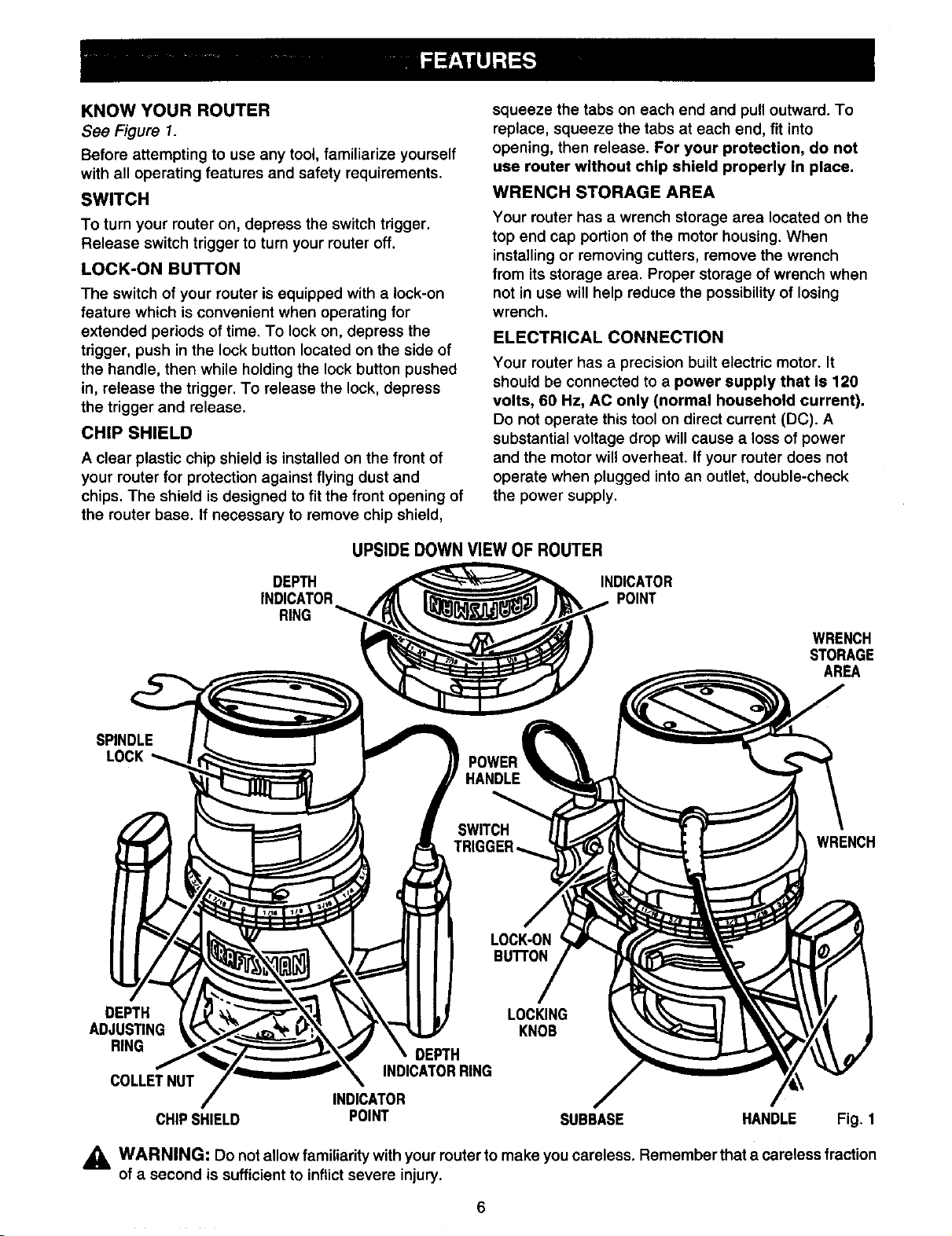
KNOW YOUR ROUTER
See Figure 1.
Before attempting to use any tool, familiarize yourself
with all operating features and safety requirements.
SWITCH
To turn your router on, depress the switch trigger.
Release switch trigger to turn your router off.
LOCK-ON BUTTON
The switch of your router is equipped with a lock-on
feature which is convenient when operating for
extended periods of time. To lock on, depress the
trigger, push in the lock button located on the side of
the handle, then while holding the lock button pushed
in, release the trigger. To release the lock, depress
the trigger and release.
CHIP SHIELD
A clear plastic chip shield is installed on the front of
your router for protection against flying dust and
chips. The shield is designed to fit the front opening of
the router base. If necessary to remove chip shield,
UPSIDEDOWN VIEW OF ROUTER
squeeze the tabs on each end and pull outward. To
replace, squeeze the tabs at each end, fit into
opening, then release. For your protection, do not
use router without chip shield properly In place.
WRENCH STORAGE AREA
Your router has a wrench storage area located on the
top end cap portion of the motor housing. When
installing or removing cutters, remove the wrench
from its storage area. Proper storage of wrench when
not in use will help reduce the possibility of losing
wrench.
ELECTRICAL CONNECTION
Your router has a precision built electric motor. It
should be connected to a power supply that is 120
volts, 60 Hz, AC only (normal household current).
Do not operate this tool on direct current (DC). A
substantial voltage drop will cause a loss of power
and the motor wil! overheat. If your router does not
operate when plugged into an outlet, double-check
the power supply.
SPINDLE
LOCK
DEPTH
ADJUSTING
RING
COLLETNUT
CHIPSHIELD POINT SUBBASE HANDLE Fig. 1
DEPTH
INDICATOR
RING
INDICATOR
POINT
WRENCH
STORAGE
AREA
POWER
WRENCH
LOCKING
KNOB
DEPTH
INDICATORRING
INDICATOR /
_ WARNING: Do not allow familiarity with your router to make you careless. Remember that a careless fraction
of a second is sufficient to inflictsevere injury.
Page 7

_1= WARNING: Your router should never be
connected to power supply when you are
assembling parts, making adjustments,
installing or removing cutters, cleaning,
or when not in use. Disconnecting router
will prevent accidental starting that could
cause serious personal injury.
INSTALLING/REMOVING CUTTERS
See Figures 2 and 3.
• Unplug your router.
_i WARNING: Failure to unplug your router could
result in accidental starting causing serious
injury.
• A spindle lock is located on the front of the motor
housing. To activate lock, push spindle lock in and
slide into lock position. See Figure 2.
,_ WARNING: To prevent damage to the spindle
or spindle lock, always allow motor to come to a
complete stop before engaging spindle lock.
SPINDLELOCK
TOLOCK
SPINDLE
Fig. 2
• Place your router upside down on table, then turn
collet nut with wrench until lock mechanism
interlocks. See Figure 3.
CUTTER
WRENCH
_i, WARNING: If you are changing a cutter
immediately after use, be careful not to touch the
cutter or collet with your hands or fingers. They
will get burned because of the heat buildup from
cutting. Always use the wrench provided.
• Remove cutters by turning collet nut counter-
clockwise enough to allow cutter to slip easily from
collet. See Figure 3. The collet is machined to
precision tolerances to fit cutters with 1/4 in.
diameter shanks.
• With your router still upside down on table, insert
shank of cutter into collet. The shank of your cutter
should be close to but not touching bottom of
collet.
• Tighten the collet nut securely by turning clockwise
with the wrench provided. See Figure 3. Push
spindle lock in and slide into unlock position.
Otherwise, the interlocking mechanism of the
spindle lock will not let you turn your router on.
COLLET
Fig. 3
Note: Spindle lock is spring loaded and will snap into
position when lock mechanism interlocks.
WARNING: Do not use cutters with undersized
shanks. Undersized shanks will not tighten
properly and could be thrown from tool causing
injury.
7
Page 8
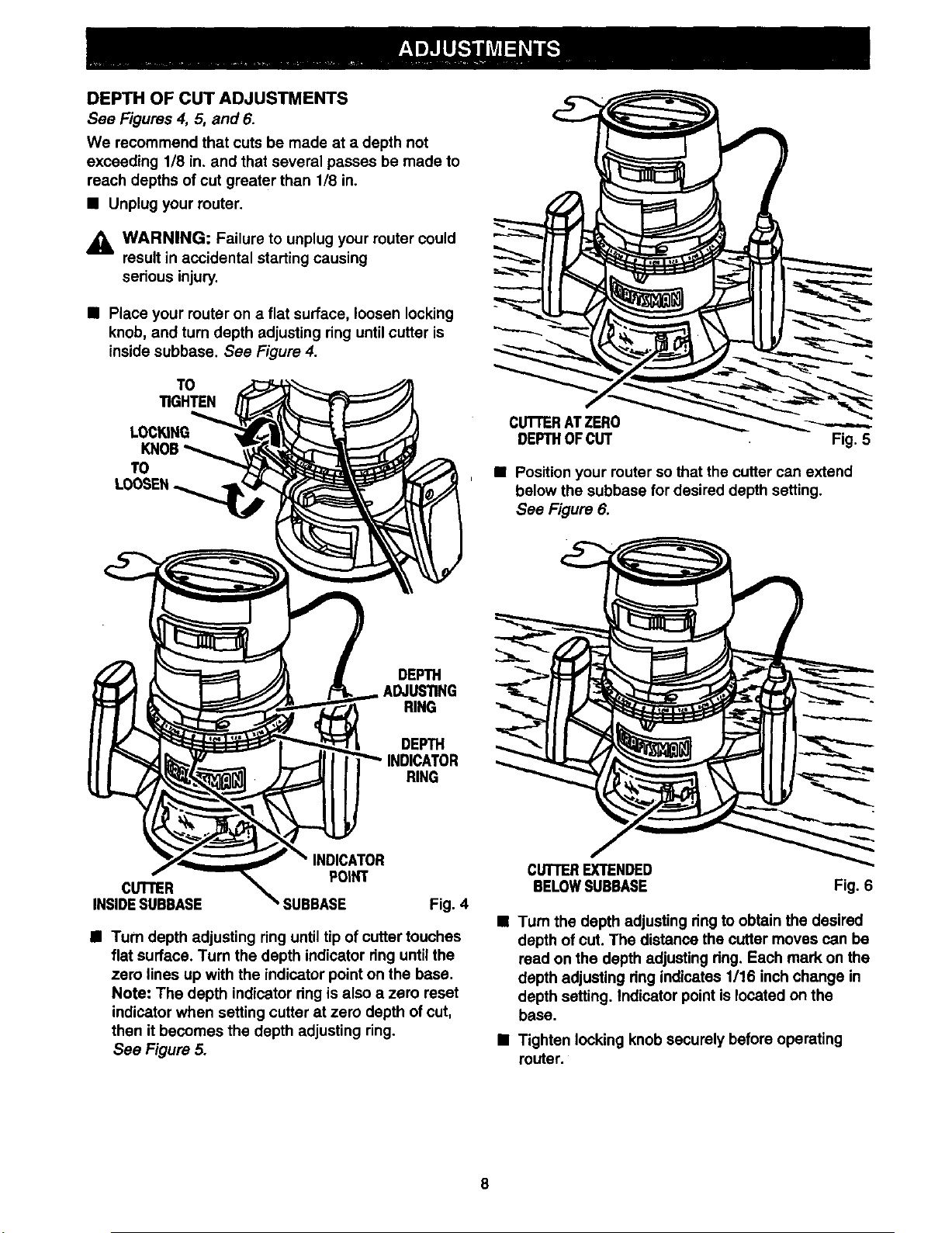
DEPTH OF CUT ADJUSTMENTS
See Figures 4, 5, and 6.
We recommend that cuts be made at a depth not
exceeding 1/8 in. and that several passes be made to
reach depths of cut greater than 1/8 in.
• Unplug your router.
,_i WARNING: Failure to unplug your router could
result in accidental starting causing
serious injury.
• Place your router on a flat surface, loosen locking
knob, and turn depth adjusting ring until cutter is
inside subbase. See Figure 4.
TO
TIGHTEN
LOCKING
KNOB
TO
CUTrERATZERO
DEPTHOFCUT Fig. 5
• Position your router sothat the cutter can extend
below the subbase for desired depth setting.
See Figure 6.
DEPTH
ADJUSllNG
RING
DEPTH
RING
INDICATOR
CUTrER
INSIDESUBBASE ' SUBBASE Fig. 4
• Turn depth adjusting ring untiltip of cutter touches
flat surface. Turn the depth indicator ringuntil the
zero lines up with the indicator point on the base.
Note: The depth indicator ring is also a zero reset
indicator when setting cutter at zero depth of cut,
then it becomes the depth adjusting ring.
See Figure 5.
POIHT
CUTTEREXTENDED
BELOWSUBBASE Fig. 6
•Tum the depth adjusting ring to obtain the desired
depth of cut. The distance the cutter moves can be
read on the depth adjusting dng. Each mark on the
depth adjusting dng indicates 1/16 inch change in
depth setting. Indicator point is located on the
base.
• Tighten locking knob securely before operating
router.
8
Page 9

DEPTHOFCUTADJUSTMENTSWHEN
ROUTERISMOUNTEDTOA ROUTERTABLE
See Figure 7.
The depth of cut is readable from both sides of the depth
indicator ring. The bottom dng is convenient when using
your router mounted upside down to a router table. The
indicator point on the base can also be used when using
your router mounted to a router table.
Set the cutter at zero depth of cut, rotate depth
indicator ring to desired depth of cut on the scale,
then tighten locking knob securely.
FOR ROUTERTABLE USE ONLY
INDICATOR DEPTH
POINT INDICATORRING
Fig. 7
ROUTER TABLES
The use of Craftsman reuters on router tables offered
by other manufacturers has not been investigated for
compliance with applicable safety standards.
_ WARNING: Do not use with router tables that
fail to conform to safe wood working practices
and offer proper guarding for the cutter. Failure
to comply can result in an accident causing
possible serious injury.
HELPFUL HINTS
_/ Always clamp workpiece securely before muting.
_/ A safe operator isone who thinks ahead.
•/ Always wear eye protection when muting.
,/ Make setup adjustments carefully. Then double
check. Measure twice and cut once.
J Keep cutters clean and preperly sharpened.
4' Don't let familiarity make you careless.
J Study all safety rules and do the job safely.
/ Never place your hands in jeopardy.
J Make certain clamps can't loosen while in use.
J Test difficultsetups on scrap -- Don't waste
lumber.
J Pla'neach operation before you begin.
4" Provide for smoother operation by cleaning your
muter frequently. Shake muter or blow with an air
jet to remove sawdust buildup.
Think safety by thinking ahead.
ROUTING
See Figure 8.
For ease of operation and maintaining proper control,
your router has two handles, one on each side of the
router base. When using your router hold it firmly with
both hands as shown in Figure 8.
Turn router on and let motor build to its full speed,
then gradually feed cutter intoworkpiece. Remain
alert and watch what you are doing. Do not operate
router when fatigued.
HANDLE
POWER
HANDLE
PRACTICE BEFORE ACTUAL USE
We suggest that you practice with your router before
installing a cutter and making cuts in wood. Check
the following before connecting your router to
power supply.
• Make sure power supply is 120 volts, 60 Hz, AC
only.
• Make sure the spindle lock isinthe unlocked
position.
• Make sure the tdgger is not in the lock.on position.
• Make sure there is not a cutter in the toilet.
• Make sure the toilet does not extend below the
subbase.
• Plug your routerinto power supply.
• Grasp your routerfirmly with both hands and turn on.
,_ WARNING'- Keep a firm grip on router with both
hands at all times. Failure to do so could result in
loss of control leading to possible serious injury.
9
Fig. 8
Page 10

FREEHAND ROUTING
See Figure 9.
FREEHANDROUTING Fig. 9
When used freehand, your router becomes a flexible
and versatile tool. This flexibility makes it possible to
easily rout signs, relief sculptures, etc.
There are two basic techniques
for freehand routing:
• Routing letters, grooves, and patterns into wood.
See Figure 9.
• Routing out the background, leaving the letters
or pattern raised above the surface.
When freehand routing, we suggest the following:
• Draw or layout the pattern on workpiece.
• Choose the appropriate cutter.
Note: A core box or V-groove bit is often used for
routing letters and engraving objects. Straight bits
and ball mills are often used to make relief
carvings. Veining bitsare used to carve small,
intricate details.
• Rout the pattern in two or more passes. Make the
first pass at 25% of the desired depth of cut. This
will provide better control as well as being a guide
for the next pass.
• Do not rout deeper than 1/8 in. per pass or cut.
WARNING: Do not use large router bits for
A
freehand routing. Use of large router bits when
freehand routing could cause loss of control or
create other hazardous conditions that could
cause possible serious personal injury.When
using a router table, large router bits should be
used for edging only. Do not use router bits that
are larger in diameter than the opening in router
base for any purpose.
RATE OF FEED
IMPORTANT: The whole "secret" of professional
routing and edge shaping lies in making a careful
setup for the cut to be made and in selecting the
proper rate of feed.
PROPER FEEDING
The right feed is neither too fast nor too slow. It is the
rate at which the bit is being advanced firmly and
surely to produce a continuous spiral of uniform chips
-- without hogging into the wood to make large
individual chips or, on the other hand, to create only
sawdust. If you are making a small diameter, shallow
groove in soft, dry wood, the proper feed may be
about as fast as you can travel your router along your
guide line. On the other hand, ifthe bit is a large one,
the cut is deep or the wood is hard to cut, the proper
feed may be a very slow one. A cross-grain cut may
require a slower pace than an identical with grain cut
in the same workpiece.
There is no fixed rule. You will learn by experience
from practice and use. The best rate of feed is
determined by listening to the sound of the router
motor and by feeling the progress of each cut. Always
test a cut on a scrap piece of the workpiece wood,
beforehand.
FORCEFEEDING
Clean, smooth routing and edge shaping can be done
only when the bit is revolving at a relatively high
speed and istaking very small bites to produce tiny,
cleanly severed chips. If your router is forced to move
forward too fast, the RPM of the bit becomes slower
than normal in relation to its forward movement. As a
result, the bit must take bigger bites as it revolves.
"Bigger bites" mean bigger chips, and a rougher
finish. Bigger chips also require more power, which
could result in the router motor becoming overloaded.
Under extreme force-feeding conditions the relative
RPM of the bit can become so slow -- and the bites it
has to take so large -- that chips will be partially
knocked off (rather thanfully cut off), with resulting
splintering and gouging of the workpiece.
See Figure 10.
10
Page 11
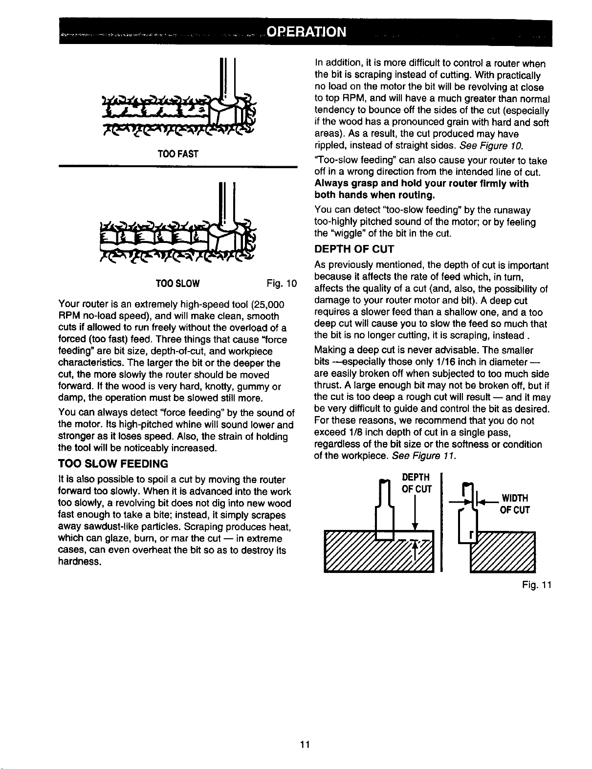
TOOFAST
TOOSLOW Fig.10
Your router is an extremely high-speed tool (25,000
RPM no-load speed), and will make clean, smooth
cuts ifallowed to run freely without the overload of a
forced (too fast) feed. Three things that cause "force
feeding" are bit size, depth-of-cut, and workpiece
characteristics. The larger the bit or the deeper the
cut, the more slowly the router should be moved
forward. If the wood is very hard, knotty, gummy or
damp, the operation must be slowed stillmore.
You can always detect "force feeding" by the sound of
the motor. Its high-pitched whine will sound lower and
stronger as it loses speed. Also, the strain of holding
the tool will be noticeably increased.
TOO SLOW FEEDING
It is also possible to spoil a cut by moving the router
forward too slowly. When it is advanced into the work
too slowly, a revolving bit does not dig into new wood
fast enough to take a bite; instead, it simply scrapes
away sawdust-like particles. Scraping produces heat,
which can glaze, burn, or mar the cut -- in extreme
cases, can even overheat the bit so as to destroy its
hardness.
In addition, it is more difficult to control a routerwhen
the bit is scraping instead of cutting. With practically
no load on the motor the bit will be revolving at close
to top RPM, and will have a much greater than normal
tendency to bounce off the sides of the cut (especially
if the wood has a pronounced grain with hard and soft
areas). As a result,the cut produced may have
rippled, instead of straight sides. See Figure 10.
'q'oo-slow feeding" can also cause your router to take
off in a wrong directionfrom the intended line of cut.
Always grasp and hold your router firmly with
both hands when routing.
You can detect "too-slow feeding" by the runaway
too-highly pitched sound of the motor; or by feeling
the "wiggle" of the bit inthe cut.
DEPTH OF CUT
As previously mentioned, the depth of cut is important
because it affects the rate of feed which, inturn,
affects the quality of a cut (and, also, the possibilityof
damage to your router motor and bit). A deep cut
requires a slower feed than a shallow one, and a too
deep cut will cause you to slow the feed so much that
the bit is no longer cutting, it is scraping, instead.
Making a deep cut is never advisable. The smaller
bits --especially those only 1/16 inch in diameter-
are easily broken off when subjected to too much side
thrust. A large enough bit may not be broken off, but if
the cut is too deep a rough cut will result -- and it may
be very difficult to guide and controlthe bitas desired.
For these reasons, we recommend that you do not
exceed 118inch depth of cut in a single pass,
regardless of the bit size or the softness or condition
ofthe workpiece. See Figure 11.
DEPTH
WIDTH
OFCUT
OFIUT
W/YJ d
11
Fig. 11
Page 12

Tomakedeepercutsitisthereforenecessaryto
makeasmanysuccessivepassesasrequired,
loweringthebit1/8inchfor each new pass. In order to
save time, do all the cutting necessary at one depth
setting, before lowering the bit for the next pass. This
will also assure a uniform depth when the final pass is
completed. See Figure 12.
2ND.PASS
2ND. 1ST.
PASS PASS
Fig. 12
DIRECTION OF FEED AND THRUST
The router motor and bitrevolve in a clockwise direc-
tion. This gives the tool a slight tendency to twist (in
your hands) in a counterclockwise direction, especially
when the motor revs up (as at starting).
Because of the extremely high speed of bit rotation
dudng a "proper feeding" operation, there is very little
kickback to contend with under normal conditions.
However, should the bit strike a knot, hard grain,
foreign object, etc. that would affect the normal
progress of the cutting action, there will be a slight
kickback-- sufficient to spoil the trueness of your cut if
you are not prepared. Such a kickback is always in the
direction opposite to the direction of bit rotation.
To guard against such a kickback, plan your setup and
direction of feed so that you will always be thrusting
the tool -- to hold it against whatever you are using to
guide the cut-- in the same direction that the leading
edge of the bit is moving. In short, the thrust should be
in a direction that keeps the sharp edges of the bit
continuously biting straight into new (uncut) wood.
ROUTING
Whenever you are routing a groove, your travel
should be in a direction that places whatever guide
you are using at the rigHt-handside. In short, when
the guide is positioned as shown in the first part of
Figure 13, tool travel should be left to right and
counterclockwise around curves. When the guide is
positioned as shown in the second part of Figure 13,
tool travel should be right to left and clockwise around
curves. If there is a choice, the first setup is generally
the easiest to use. In either case, the sideways thrust
you use is against the guide.
GUIDEOUTSIDE
ROTATION
THRUST
ROTATION
FEED GUIDE
GUIDEINSIDE
ROTATION_"_
Gu,oE-- '/J
ROTATION_____
_ THRUST
/
FEED
Fig. 13
12
Page 13

STARTING AND ENDING A CUT
INTERNAL ROUTING
Tilt router and place on workpiece, letting edge of
subbase contact workpieoe first. Be careful not to let
router bit contact workpiece. Turn router on and let
motor build to its full speed. Gradually feed cutter into
workpiece until subbase is level with workpiece.
_1 WARNING: Keep a firm grip on router with both
hands at all times. Failure to do so could result in
loss of control leading to possible serious injury.
Upon completion of cut, turn motor off and let it come
to a complete stop before removing router from work
surface.
_1, WARNING: Never pull router out of work and
place upside down on work surface before the
cutter stops.
EDGING WITH PILOT BITS
See Figure 14.
II .ouTE. II
WORKI I I /
Whenever the workpiece thickness together with the
desired depth of cut (as adjusted by router depth
setting) are such that only the top part of the edge is
to be shaped (leaving at least a 1/16 inch thick uncut
portion at bottom), the pilot can ride against the uncut
portion, which will serve to guide it. See Figure 14.
However, if the workpiece is too thin or the bit set too
low so that there will be no uncut edge to ridethe pilot
against, an extra board to act as a guide must be
placed under the workpiece. This "guide" board must
have exactly the same contour -- straight or curved
-- as the workpiece edge. If it is positioned so that its
edge is flush with the workpiece edge, the bit will
make a full cut (in as far as the bit radius). On the
other hand, if the guide is positioned as shown in
Figure14 (out from the workpiece edge), the bit will
make less than a full cut -- which will alter the shape
of the finished edge.
Note: Any of the piloted bits can be used without a
pilot for edge shaping with guides, as preceding. The
size (diameter) of the pilot that is used determines the
maximum cut width that can be made with the pilot
against the workpiece edge - the small pilot exposes
all ofthe bit; the large one reduces thisamount by
1/16 inch.
TOPEDGESHAPING
|
PILOT
WHOLE EDGESHAPING Fig. 14
Arbor-type bits with pilots are excellent for quick,
easy, edge shaping, They will follow workpiece edges
that are either straight or curved. The pilot prevents
the bit from making too deep a cut; and holding the
pilot firmly in contact with the workpiece edge
throughout prevents the cut from becoming too
shallow.
EDGE ROUTING
Place router on workpiece, making sure the router bit
does not contact workpiece. Turn router on and let
motor build to its full speed. Begin your cut, gradually
feeding cutter into workpiece.
_k WARNING: Keep a firm grip on router with both
hands at all times. Failure to do so could result in
loss of control leading to possible serious injury.
Upon completion of cut, turn motor off and let it come
to a complete stop before removing router from work
surface.
d_i WARNING: Never pull router out of work and
place upside down on work surface before the
cutter stops.
ROUTING WITH GUIDE BUSHINGS
When using the Template Guide Bushings Item No.
9-25082 with your router, you must visually center the
bit with the bushing before beginning your cut. Your
router subbase may be adjusted by loosening the
screws holding the subbase to your router. Be sure
locking knob is tightened before centering bit in
bushing. After centedng bit with bushing, tighten
screws securely.
13
Page 14

,_ WARNING: When servicing, use only identical
Craftsman replacement parts. Use of any other
part may create a hazard or cause product
damage.
GENERAL
Only the parts shown on parts list, page 17, are
intended to be repaired or replaced by the customer.
All other parts represent an important part of the
double insulation system and should be serviced only
by a qualified Sears service technician.
Avoid using solvents when cleaning plastic parts.
Most plastics are susceptible to damage from various
types of commercial solvents and may be damaged
by their use. Use clean cloths to remove dirt, carbon
dust, etc.
_k WARNING: Do not at any time let brake fluids,
gasoline, petroleum-based products, penetrating
oils, etc. come in contact with plastic parts. They
contain chemicals that can damage, weaken or
destroy plastic.
It has been found that electric tools are subject to
accelerated wear and possible premature failure when
they are used on fiberglass boats, sports cars,
wallboard, spackling compounds, or plaster. The
chips and grindings from these materials are highly
abrasive to electric tool parts such as bearings,
brushes, commutators, etc. Consequently, it is not
recommended that this tool be used for extended
work on any fiberglass material, wallboard, spackling
compounds, or plaster. During any use on these
materials it is extremely important that the tool is
cleaned frequently by blowing with an air jet.
LUBRICATION
All of the bearings in this tool are lubricated with a
sufficient amount of high grade lubricant for the life of
the unit under normal operating conditions. Therefore,
no further lubrication is required.
EXTENSION CORDS
The use of any extension cord will cause some loss of
power. To keep the loss to a minimum and to prevent
tool overheating, use an extension cord that is heavy
enough to carry the current the tool will draw.
A wire gage size (A.W.G.) of at least 14 is
recommended for an extension cord 100 feet or less
in length. When working outdoors, use an extension
cord that is suitable for outdoor use. The cord's jacket
will be marked WA.
CAUTION: Keep extension cords away from the
A
cutting area and position the cord so that it will
not get caught on lumber, tools, etc., during
cutting operation.
_ WARNING: Check extension cords before each
use. If damaged replace immediately. Never use
tool with a damaged cord since touching the
damaged area could cause electrical shock
resulting in serious injury.
Extension cords suitable for use with your router are
available at your nearest Sears Retail Store.
,_ WARNING: Always wear safety goggles or
safety glasses with side shields during power
tool operation or when blowing dust. If operation
is dusty, also wear a dust mask.
PROPER CARE OFCU'n'ERS
Get faster more accurate cutting results by keeping
cutters clean and sharp. Remove all accumulated
pitch and gum from cutters after each use.
When sharpening cutters, sharpen only the inside of
the cutting edge. Never grind the outside diameter. Be
sure when sharpening the end of a cutter to grind the
clearance angle the same as originally ground.
PROPER CARE OFCOLLET
From time to time, it also becomes necessary to clean
your collet and collet nut. To do so, simply remove
collet nut from collet and clean the dust and chips that
have collected. Then return conet nut to its original
position.
14
Page 15

SWITCH REPLACEMENT
See Figures 15and 16.
• Unplug your router.
_k WARNING: Failure to unplug your router could
result in accidental starting causing
serious injury.
• Remove screws (A) and handle cover (B).
See Figure 15.
• Make lead connections to new switch. Push each
lead as far as possible into proper switch
receptacle. Pull on leads to check lead connections
with lead receptacles.
• Locate switch in handle and place leads so they
won't be pinched or contact screws when handle
cover is replaced.
• Make sure molded bend relief (C) is correctly
positioned in switch handle, then replace handle
cover and screws.
• Tighten all screws securely.
LIGHT BULB REPLACEMENT
See Figure 17.
• Unplug your router.
A
Fig. 15
Note the location of the molded bend relief (C)
on the power handle cord. Also note all wiring
In the handle end how each lead is connected
to the switch. Connections and wiring position
must be identical when installing new switch.
See Figure 15.
Remove leads from switch (D) by inserting a 1/32
in. diameter nail or pin into switch lead receptacle
and pulling on lead as shown in Figure 16.
Remove nail or pin with a twisting, pulling motion.
LEAD
_ WARNING: Failure to unplug router could
result in accidental starting causing serious
injury.
• Remove cutter from router. Refer to page 7 to
remove cutter.
• Adjust router to maximum height.
• Remove screws (A) and subbase (B).
See Figure 17.
A
C
D I
your
B
E
POWER
HANDLE
CORD
WHITE
1/32In, DIAMETER
NAILORPIN
RED
WORK
LIGHT
Fig. 17
• Remove screw (C) and work light lens (D).
• With bulb (E) pointing toward you, push bulb in and
turn to the left to remove from bulb socket.
Note: Light bulb removal and installation is similar
to removing and installing a standard automotive
bulb.
• Install new bulb by reversing the above procedure.
• Reassemble all parts and tighten screws securely.
Fig. 16
15
Page 16

CRAFTSMAN ROUTER - MODEL NUMBER 315.175140
I I
SEE NOTE "A"
24 25
21
9
10
NOTE: "A" - The assembly shown represents an Important part of the Double Insulated System. To avoid
the possibility of alteration or damage to the System, service should be performed by your near-
est Sears Repair Center. Contact your nearest Sears Retsll Store for Service Center Information.
16
Page 17

CRAFTSMAN ROUTER- MODEL NUMBER 315.175140
The model number will be found on a plate attached to the motor housing. Always mention the model number |
in all correspondence regarding your ROUTER or when ordering repair parts,
SEE BACK PAGE FOR PARTS ORDERING INSTRUCTIONS
PARTS LIST
Key Pad
No. Number
1 983256-001
2 970692-001
3 989985-903
4 983217-001
5 974131-002
6 623166-006
7 622832-014
8 606066-004
9 617966-030
10 970697-000
11 973735-002
12 606688-002
13 998586-001
14 612191-004
15 989684-001
16 975041-001
17 610930-001
18 970696-000
19 610951-001
20 998895-001
21 623173-006
22 999603-001
23 931744-059
24 999053-003
25 989935-006
972000-975
Description Quan.
Data Plate .............................................................................................. 1
Label ...................................................................................................... 1
Collet Nut (1/4 in.) ................................................................................. 1
Depth Adjusting Ring Assembly (Includes Key No. 24) ........................ 1
Depth Indicator Ring.............................................................................. 1
* Square Head Bolt(#1/4-20 x 1-1/4 in.).................................................. 1
Roll Pin .................................................................................................. 1
* Screw (#10-32 x 3/4 in. Pan Hd.) .......................................................... 4
* Screw (#8-10 x 5/8 in. Pan Hd.) ............................................................ 8
Handle Assembly .................................................................................. 1
Base ...................................................................................................... 1
Chip Shield ............................................................................................ 1
* Screw (#10-32 x 1/4 in. Pan Hd.) .......................................................... 3
Subbase ................................................................................................ 1
* Screw (#6-32 x 1/4 in. T. C. Pan Hd.) ................................................... 1
Work Light Lens .................................................................................... 1
Light Housing ........................................................................................ 1
Power Handle Assembly ....................................................................... 1
Light Bulb .............................................................................................. 1
Switch .................................................................................................... 1
Wire Nut ................................................................................................ 1
Knob ...................................................................................................... t
Washer .................................................................................................. 3
* Screw (#5-10 x 1/2 in. Fil. Hd.) .............................................................. 2
Wrench (9/16 in.) ................................................................................... 1
Operator's Manual
I
* Standard Hardware Item - May Be Purchased Locally
17
Page 18

For repair of major brand appliances in your own home...
no matter who made it, no matter who sold it!
1-800-4-MY-HOM EsMAnytime,dayornight
(1-800-469-4663)
www.sears.com
To bring in products such as vacuums, lawn equipment and electronics
for repair, call for the location of your nearest Sears Parts & Repair Center
1-800-488-1222 Anytime, day or night
www.sears.com
For the replacement parts, accessories and owner's manuals
that you need to do-it-yourself, call Sears PartsDirect sM!
1-800-366-PART 6 a.m. - 11 p.m. CST,
(1-800-366"7278) 7 days a week
www.sears.condpartsdirect
To purchase or inquire about a Sears Service Agreement:
1-800-827-6655
7 a.m. - 5 p.m. CST, Mon.- Sat.
Para pedir servicio de reparacibn a domicilio,
y para ordenar piezas con entrega a domicilio:
1-888-SU-HOGAR sM
(1-888-784"6427)
® Registered Trademark / TM Trademark of Sears, Roebuck and Co.
O Sears, Roebuck and Co. ® Mama Reglstrada / _'_ Mama de Fdbdca de Sears, Roebuck and Co.
Au Canada pour serviceen fran_ais:
1-877-LE-FOYER sM
(1-877-533-6937)
Page 19

Manual del Usuario
TUPI
Aislamiento Doble
Modelo No
315.175140
Conserve este manual
para referencia futura
ATENClON: Lea cuidadosamente
todas las Reglas de Seguridad y las
Instruccionesantes de usar esta
herramienta.
Sears, Roebuck and Co., 3333 Beverly Rd., Hoffman Estates, IL 60179 USA
Visite la p_gina Web de Craftsman: www.sears.com/craftsman
972000-975
5-02
• Seguridad
• Caracter|sticas
• Ajustes
• Funcionamiento
• Mantenimiento
• Lista de Repuestos
®
Page 20

• Tabla de Materias ........................................................................................................................................... 2
• Garantia .......................................................................................................................................................... 2
• Introducci6n .................................................................................................................................................... 2
• Reglas para Funcionamiento Seguro ......................................................................................................... 3-4
• Especificaciones del Producto ....................................................................................................................... 5
• Desempaque .................................................................................................................................................. 5
• Accesodos ...................................................................................................................................................... 5
• Caracteristicas ............................................................................................................................................... 6
• Ajustes ......................................................................................................................................................... 7-9
• Funcionamiento ......................................................................................................................................... 9-13
• Mantenimiento ......................................................................................................................................... 14-15
• Vista Esquemdtica y Lista de Repuestos ................................................................................................ 16-17
• Pedidos de Repuestos / Servicio ................................................................................................................. 18
GARANTIA COMPLETA DE UN AI_IO DEL TUPI [RRFTSMRN
Si este Tupf £RRFTSMRN no le proporciona completa satisfacci6n a partir de un aSo desde la fecha de compra,
DEVUELVALO AL ALMACEN SEARS MAS CERCANO EN LOS ESTADOS UNIDOS y Sears Io reemplazard
gratuitamente.
Si este Tupf CRRFTSMRNse usa para prop6sitos comerciales o de alquiler, esta garantfa es vdlida solamente
durante 90 dlas desde la fecha de compra.
Esta garant{a le otorga derechos legales especfficos y usted puede ademds tener otros derechos que varfan de
un estado a otro.
Sears, Roebuck and Co., Dept. 817 WA, Hoffman Estates, IL 60179
Su tupf tiene muchas caracterfsticas que contribuyena
facilitar y hacer rods agradable su trabajo. Se ha dado
prioridad mdxima a la seguridad, rendimiento y '
dependabilidad en el diseSo de este tupi por Io cual es
fdcil de mantener y operar.
Este sfmbolo le indica de
su seguridad.
_k ADVERTENCIA:
La utilizaci6n de cualquier tup{ puede causar la proyeccibn de objetos extraSos a sus ojos, Io
cual puede ocasionar daSos oculares severos. Antes de comenzar a usar la herramienta
mecdnica, siempre use sus lentes protectores o gafas de seguridad con protecci6n lateral y
una mdscara completa cuando sea necesario. Recomendamos una M_.scara de Visibn Amplia
para usar sobre sus lentes protectores o lentes de seguridad estdndar, con protecci6n lateral,
disponible en los Almacenes Sears. Siempre use lentes protectores que ¢umplan con la
norma ANSI Z87.1 y que esten asi marcados.
importantes reglas seguridad, iSignifica atenciSn! Existe riesgo para
_ ATENCION: Lea cuidadosamente todoeste
manual antes de usar su nuevo tupf. Preste mucha
atenci6na las Reglas para FuncionamientoSeguro
asi como alas Advertencias y Avisos. Si usted
utitizaeltupfdebidamente y solamente para el
prop6sitoque ha sido disefiado, usted disfrutardde
muchosaSos de servicio seguro.
2
Page 21

Estoss|mbolosdesegurldadseutilizanpareadvertirlesobreclertosrlesgosposibles.Lossimbolosde
segurldadylasexpllcaclonesqueacompafianestossimbolosmerecencuidadosaatencibnycomprenslbn.
Lasadvertenclasporelmismasnoelimlnannlngdnpeligro.LasInstruccloneso lasadvertenclasquese
proporclonannoreemplazanalasmedidasadecuadasdeprevenclbndeaccldentes.
SIMBOLO SIGNIFICADO
A
A
SIMBOLO DE ALERTA SOBRE SEGURIDAD: Indica atenci6n, advertenciao peligro. Puede
usarseconjuntamentecon otrossfmboloso pictogramas.
PELIGRO: Si no se obedece una advertenciade seguridadpuede lesionarse esi mismo y a otros.
Siempresiga las precaucionesde seguridad para reducirel riesgode incendio,choque electrico y
lesibn personal.
ADVERTENCIA: Si no se obedece una advertencia de seguridad puede lesionarse a si mismoy a
otros.Siempre siga las precaucionesde seguridad para reducirel riesgode incendio,choque el(_ctrico
y lesi6n personal.
ATENClON: Si no se obedece una advertencia de seguridad puede lesionarse a si mismo y a otros.
Siempre siga las precaucionesde seguridadpara reducir el riesgode incendio,choque el_ctricoy
lesibn personal.
NOTA: Informaci6n o instrucciones vitalespara el funcionamiento o mantenimiento de la herramienta.
AISLAMIENTO DOBLE
El aislamientodobte es un concepto de seguridad, en las
herramientas rnecdnicas electricas, que elimina la
necesidad del cord6n normal trifilar puesto a tierra.
Todas las piezas met&licas expuestas est_.naisladas de
los componentes internesdel motor con aislamiento
protector. Las herramientascon dobleaislamiento no
necesitan ser puestasa tierra.
IMPORTANTE
La reparacibn de las herramientas con aislamiento doble
requiere extremo cuidado y conocimiento del sistema y
debe ser realizada solarnente pot un t_cnico de servicio
calificado. Para toda reparaci6n, le sugerimos que neve
la herramienta a su Almac_n Sears m&s cercano.
Siempre use repuestos de f&brica originales cuando
efect0e alguna reparacibn.
ADVERTENCIA: No intentehacerfuncionar
esta herramienta sin antes haber leido y
oomprendido bien todas las instrucciones, las reglas
de seguridad, etc. indicadas en este manual. El
incumplimiento de estas instrucciones puede
ooasionar accidentes, incendio, choque el_ctrico o
lesiones personales graves. Conserve el manual
del usuario y estt_dielo frecuentemente para poder
utilizar el equipo con seguridad y poder comunicar
las instrucciones apropiadas a otras personas que
utilicen esta herramienta.
LEA TODAS LAS INSTRUCCIONES
• CONOZCA SU HERRAMIENTA MECANICA. Lea
cuidadosamente el manual del usuario. Aprenda sus
aplicaciones y limitaciones asi como tambi_n los riesgos
potenciales especificos relacionados con esta
herramienta.
• PROTEJASE CONTRA CHOQUE ELECTRICO evitando
contacto del cuerpo con las superficies puestas a tierra.
Por ejemplo: las cajas de las tuberias, radiadores,
estufas, refrigeradores.
• MANTENGA LOS PROTECTORES EN SU LUGAR yen
buen estado de funcionamiento.
• MANTENGA EL AREA DE TRABAJO LIMPIA. Los
lugares y bancos de trabajo desordenados invitan a los
accidentes.
• EVITE TODOS LOS AMBIENTES PELIGROSOS. No
use su herramienta mec&nica donde haya humedad, en
lugares mojados o donde est6 expuesta ala Iluvia.
Mantenga el lugar de trabajo bien iluminado.
• MANTENGA A LOS NIl;lOS Y A LOS ESPECTADORES
ALEJADOS, Todos los espectadores deben usar lentes
de seguridad y ser mantenidos a una distancia prudente
del _rea de trabajo. No deje que los espectadores
toquen la herramienta o el cordbn de extensi6n,
• ALMACENAMIENTO DE LAS HERRAMIENTAS QUE
NO SE USAN. Cuando no est_n en uso las
herramientas deben ser guardadas en un lugar seco, alto
o bajo Ilave - fuera del alcance de los nifios.
• NO FUERCE LA HERRAMIENTA. El trabajo quedar&
hecho mejor y de manera m&s segura si la herramienta
trabaja ala velocidad a la cual fu6 disefiada.
• USE LA HERRAMIENTA CORRECTA. No fuerce a una
herramienta o a un accesorio pequer_o que haga el
trabajo de una herramienta de servicio pesado. No use
ia herramienta para prop6sitos que no ha sido diseflada.
Por ejemplo, no use una sierra circular pare cortar
troncos o ramas de _rboles.
• USE VESTIMENTA ADECUADA. No use ropa o joyas
sueltas, pues pueden quedar atrapadas en las piezas
m6viles de la herramienta y causar lesibn personal. Se
recomienda usar guantes de gorna y calzado
antirresbaladizo cuando se trabaja al aire libre. Tambi6n,
prot_jase el cabello largo y suj_telo a fin de evitar que
quede atrapado en los respiraderos cercanos.
• USE SIEMPRE LENTES PROTECTORES. Los anteojos
regulares tienen solamente lentes resistentes al impacto;
ellos no son lentes de seguridad.
3
Page 22

• PROTEJA SUS PULMONES. Utiliceuna m_L_cara
contrael polvosi laoperacibnde cortevaa despedir
mucho polvo.
• PROTEJA SU AUDIClON. Utiliceproteccibnparalos
oidosdurantepeHodosprolongadosde funcionamiento.
• NO ABUSE DEL CORDON. Nuncatransportela
herramientaporel cordbno latiredet cordbnpara
desconectadadeltomacorriente.Mantengaelcord6n
alejadodelcalor,del aceitey de loshordesafilados.
• SUJETE EL TRABAJO. Use mordazas oun tornillode
bancopara sujetarel trabajo. Es m_sseguroque usar
su manoy ledejaambasmanes libresparautilizarla
herramienta.
• NO USE LA HERRAMIENTA A UNA DISTANCIA
DEMASIADO ALEJADA. Mantengasiempreunbuen
equilibrioy una posicibnfirme. No lautiliceen una
escalerao enun apoyoinestable.Asegurelas
herramientascuandotrabajeen posicionesaltas.
• MANTENGA BIEN CUIDADA LA HERRAMIENTA.
Mantengala herramientaafiladaen todomomento y
limpiapara unrendimientomejory m_sseguro. Siga las
instruccionesdelubricacibny de cambiode accesorios.
• DESCONECTE I.AS HERRAMIENTAS. Cuandono
est_nen uso,antesdelservicioocuandocambia
accesorios, todaslas herramientasdebende estar
desconectadasde lafuente de alimentacibn.
• SAQUE LAS LLAVES DE AJUSTE Y LLAVES
INGLESAS. Acost0mbresea verificarsise han sacado
todaslasIlavesde laherramientaantesde ponerlaen
marcha.
• EVITE LA PUESTA EN MARCHA ACCIDENTAL. No
transporte las herramientas que est&n enchufadas con
dedo sobre el interruptor. AsegOrese de que el
interruptor est_ en la posicibn "OFF" (apagado) al
enchufarla.
• ASEGURESE DE QUE SU CORDON DE EXTENSION
ESTE EN BUEN ESTADO. Cuando use un cord6n de
extensi6n, aseg_rese de qua su di_.metro sea suficiente
para portar la cordente qua necesita su herramienta. Un
cordbn de calibre inferior causaret una p_rdida en el
voltaje de linea resultando en p_rdida de potencia y
sobrecalentamiento. Se recomienda un cord6n de pot Io
menos calibre 14 (A.W.G.) para un cordbn de extensi6n
de lOg pies o menos de largo. No se recomienda'el uso
de un cord6n qua sobrepase los 100 pies de largo.
Mientras mds pequet_o es el n_mero del calibre, mayor
es el di_metro del cord6n.
• USE CORDONES DE EXTENSION APROPIADOS
PARA EL EXTERIOR. Cuando la herramienta es usada
al aire libre use solamente cordones de extensi6n
adecuados para uso al aire libra. Los cordones
aprobados para uso al aire libra est_n marcados con el
sufijo W-A, por ejemplo - SJTW-A o SJOW-A.
• MANTENGA LAS FRESAS LIMPIAS Y AFILADAS. Las
fresas afiladas reducen a un mfnimo la p_rdida de
velocidad y ei contragolpe.
• MANTENGA LAS MANOS ALEJADAS DEL AREA DE
CORTE. Mantenga las manos alejadas de las fresas.
No trate de alcanzar por debajo del trabajo cuando la
fresa est_ girando. No intente sacar material, pedazos o
astillas cuando el cortador est_ girando.
• NUNCA USE EN UNA ATMOSFERAEXPLOSIVA. I-as
chispasnormalesdel motorpueden hacerexplotar los
vapores.
• INSPECCIONE PERIODICAMENTELOS CORDONES
DE LA HERRAMIENTAy si est_n dahados,hdgalos
repararpot el centrodeservicioSears. Siempreestd
atentode la ubicaci6ndelcord6n.
• INSPECCIONE LOSCORDONES DE EXTENSION
PERIODICAMENTE yreempl_lcelossiest._nda_ados.
• MANTENGA LAS MANIJAS SECAS, LIMPIAS YSIN
ACEITE NI GRASA. Siempreuse unpaso limpiopara
efectuar la Iimpieza.Nuncause I{quidode frenos,
gasolina,productosa base de petrbleoo solventespara
limpiar suherramienta.
• MANTENGASE ALERTAY EN CONTROL. Ponga
atenci6na Ioqua est_ haciendoy usesentidocom,',n.
No hagafuncionarla herramientacuandoest_cansado.
No se apresurepararealizarel trabajo.
• INSPECClON DE PIEZAS DAI[IADAS. Antesde seguir
utilizandola herramienta, inspeccioneparadeterminarsi
alg0nprotector ocualquierpiezaqueest_ da_ada
funcionar_ debidamente.Verifiqueelalineamientode las
piezasm6viles, si est_matascadaso si hay roturade
piezas,reviseadem_isel montaje ycualquierotroestado
que puedaafectarsufuncionamiento. Si seda_a un
protectoro cualquierotrapiezadebeser reparadao
reemplazadapotun centrodeservicioautorizado.
• NO USE LA HERRAMIENTASI EL INTERRUPTOR NO
FUNClONA DEBIDAMENTE. Haga reemplazarel
interruptordefectuosopor undistribuidorautorizado.
• INSPECClONE y saquetodoslosclavosde lamadera
el
antesde ranurar.
• NO hagafuncionaresta herramientacuandoestd bajola
influenciade drogas,alcoholo hayatornadomedicina.
• ENCHUFES POLARIZADOS. Para reducirel riesgode
choqueelectrico,laherramientatiene unenchufe
polarizado(unahoja de contactoes m_lsanchaqua la
otra). EsteenchufepuedecoFocarseen un
tomacorrientepolarizado enunasola direccibn
solamente. Si etenchufenocalza bienenel
tomacorriente,inviertaelenchufe. Si todaviano calza,
pbngaseencontactoconun electricistacalificadopara
que instaleuntomacorrienteadecuado. Nomodifique el
enchufede ningunamanera.
• CUANDO EFECTUE LABORESDE MANTENIMIENTO
USESOLAMENTE REPUESTOSCRAFTSMAN
AUTENTICOS.
• CUANDO USE ESTE TUPI CON UNA MESA PARA
TUPI, AYUDE A EVITAR POSlBLES LESIONES
GRAVES MANTENIENDO LA FRESA PROTEGIDA EN
TODO MOMENTO. Use solamente mesas para tupis,
con protectores, qua ban sido dise_lados para usar con
tupfs de este tipo, tama_o y peso.
• NO USE LA HERRAMIENTA SI SE PRODUCE
PERDIDA DE TENSION U OTRAS SITUAClONES EN
QUE EL VOLTAJE SEA BAJO. Tampoco use con
ningL_notro dispositivoqua pueda provocar cambio en el
voltaje de la fuente de energ{a.
• CONSERVE ESTAS INSTRUCClONES. Cons01telas
con frecuencia y _seLas para ayudar a otros que puedan
usar esta herramienta. Si usted presta esta herramienta
a otra persona, entregue tambi_n las instrucciones.
CONSERVE ESTAS INSTRUCCIONES
4
Page 23

_ ADVERTENClA: El polvo creado por el lijado
mec_nico, aserrado, rectificado, taladrado y otras
actividades empleadas en construcci6n contiene
productos qufmicos que se sabe causan cdncer,
defectos cong6nitos u otros dafios al sistema
reproductor. Algunos de estos productos
qufmicos son:
• plomo proveniente de pinturas a base de plomo
• sl'licecristalizada de laddllos y cemento y
otros productos de albafiileda y,
• ars6nico y cromo de madera tratada
qufmicamente.
Su desgo de exposici6n a estos productos varfa
dependiendo de cuan a menudo usted hace este
tipo de trabajo. Para reducir su exposici6n a
estos productos quimicos: trabaje en lugares
bien ventilados y utilice equipo de seguddad
aprobado, tal como mdscaras contra el polvo
especialmente disefiadas para filtrar partfculas
microscbpicas.
Profundidad del Corte 0 - 1-1/2 pulg.
Portafresa 1/4 pulg.
HP 1-1/2
Alimentacibn 120 voltios, 60 Hz, CA solamente
Su tup{ ha sido embarcado completamente armado.
Inspecci6nelo cuidadosamente para asegurarse de
que no ha ocurddo daho o rotura durante el transporte.
Si hay partes dafiadas o faltantes, Ilame a su Almac_n
Sears mds cercano para obtener piezas de repuesto
Amperios 8
Velocidad sin Carga 25.000 RPM
Cord6n El_ctrico 6 pies
Peso Neto 8,13 libras
ADVERTENClA: Si falta cualquiera de las
piezas, no haga funcionar esta herramienta hasta
que las piezas faltantes no hayan sido
reemplazadas. De Io contrario puede resoltar en
una posible lesi6n personal grave.
antes que intente utilizar el tupL Tambi_n se incluye
una Ilave y este Manual del Usuario.
LOS SIGUIENTES ACCESORIOS RECOMENDADOS
ESTAN DISPONIBLES EN LOS ALMACEN SEARS
Bujes de Gu|a de Plantilla PlanUlla para Bisagra de Puerta
Plantilla para Cola de Milano Guia de Tupf para Prop6sitos Mdltiples
Plantllla de Ensamblaje de Cajas Pant6grafo "Rout - A - Form"
FRESA FRESADE
COMBI- ACANALAR
NADA
PARA
PANEL
FRESADE
CAJADE
MACHOS
BISEL PARA
RANURA
ENV
BROCA
DERECHA
COMBINADA
DEFRESA
DERECHAY
ANGULO
ESCO-
PLEADORA
DEBISAGRA
[
COLADE REBA- GOLA CONCAVA,
MILANO JADORA ROMANA BISELADO
DE45°
L
i *FRESASCONPUNTADE CARBURO I
"25895- PARA FRESASPERFILADORASDEBORDESCON PUNTADE CARBURO
2589 - PARAFRESASPERFILADORASDEBORDESDE ACERODE ALTAVELOCIDAD
!:..... ! _--J!L!':.........................!LLZ_-=:- ........ "_
_L ADVERTENCIA: El uso de accesorios que no estdn incluidos en la lista anterior puede ser peligroso.
5
REBORDE ARBOL
DE 2589
CUARTO
BOCEL !c
CON2
COJINETES
DE BOLAS
(1/2'ySR')
"2S8_
I
Page 24

CONOZCA SU TUPI
Ver Figura 1.
Antes de intentar usarsu tupf,familiarfcese con todaslas
caracteristicasde operaci6n y los requerimientosde
seguridad.
INTERRUPTOR
Para poner en MARCHA (ON) su tupf, aprieteel gatillo.
Para APAGAR (OFF) el tupi,suelte el gatillo.
BOTON DE BLOQUEO EN MARCHA
El interruptordel tup{ est_l equipado con una
caracter{stica de bloqueo en marcha que es conveniente
cuando se trabaja durante perfodos prolongados de
tiempo. Para bloquear en marcha, apriete el gatillo,
oprima el bot6n de bloqueo en marcha situado en el lado
de ia manija, luego manteniendo oprimido el bot6n de
bloqueo en marcha, suelte el gatillo. Para desenganchar
el bloqueo en marcha, apriete y suelte el gatillo.
PROTECTOR CONTRA ASTILLAS
En la parte delantera de su tup{ se ha instalado un
protector contra astillas, de pl&stico transparente, para
protecci6n contra el potvo y las astillas que saltan. Ha
sido diseSado para que calce en la abertura delantera en
VISTA DELTUPI AL REVES
la base del tupf. Si es necesario sacarel protector contra
astillas, apriete laslengOetasen cada extremo y tire
hacia afuera. Para volvera colocarapriete las lengOetas
de cada extremo, para que calce en la abertura y
su61telas.Pare su protecclbn, no use el tupl sin tener
el protector contra astlllas en su lugar.
AREA DEL GUARDALLAVE
Su tupf tiene una &rea para guardar las Ilaves situada en
la parte superiorde la tapa del motor. Cuando instaleo
saque fresas, saque la Ilave de su_rea de
almacenamiento. Coloque la Ilave en el guardallave tan
prontocomo termine de usarlaa fin de reducirla
posibilidadde que se pierda.
CONEXlON ELECTRICA
Su tup{tiene un motor el_ctrico construido a precisibn.
Debe set conectado a una fuente de allmentacl6n de
120 voltios, 60 Hz, CA solamente (la corrlente normal
del hogar). No haga funcionar esta herramientacon
corrientecontinua(CC). Una cafda significativade
voltajepuede causar p6rdidade potenciay
sobrecalentamiento del motor. Si sutupi con efecto de
_mbolo no funciona cuando est&enchufado,vuelva a
verificarla fuente de alimentacibn.
ANILLOINDICADOR
DEPROFUNDIDAD
BLOQUE0
DEL
HUSILL0
ANILLODE BOTONDE
AJUSTEDE BLOQUEO
PROFUNDIDAD
TUERCA DEPROFUNDIOAD
PORTAFRESA
PROTECTOR PUNTO
CONTRAASTILLAS INDICADOR SUBBASE MANIJA
ANILLOINDICADOR
MANIJADE
PUESTAEN
BOTONDE
BLOQUEO
ENMARCHA
PUNTO
INDICADOR
GUARDALLAVE
L_VE
Fig. 1
_. ADVERTENCIA: No permita que su familiaridad con su tupf Io haga descuidado. Recuerde que un
descuido de una fraeci6n de segundo es suficiente para ocasionar una lesi6n grave.
6
Page 25

,_ ADVERTENClA: Su tupf no debe estar
enchufado en la fuente de alimentacibn cuando
est_ instalando piezas, haciendo ajustes,
instalando o sacando fresas, Ifmpibndoloo
cuando no est', en uso. AI desenchufar el tupf
evitard la puesta en marcha accidental que
podrfa provocar una lesibn personal grave.
INSTALACION/CAMBIO DE FRESAS
Ver Figuras 2 y 3.
• Desenchufe su tupf.
_ ADVERTENClA: Si no se desenchufa el tupf,
se puede producir la puesta en marcha
accidental causando una lesibn grave.
En el frente de la caja del motor se encuentra un
bloqueo del husillo. Para activar el bloqueo,
oprima el bloqueo del husillo y deslicelo a la
posici6n de bloqueo. Ver Figura 2.
,_ ADVERTENClA: Para evitar que se daSe el
husillo o el bloqueo del husillo, espere hasta
que el motor se detenga completamente antes
de enganchar el bloqueo del husillo.
BLOQUEODEL
HUSILLO
PARA
BLOQUEAR
DEL HUSILLC
Fig. 2
• Coloque su tupi al rev_s sobre una mesa, luego
gire la tuerca del portafresa con una Ilave hasta
que el mecanismo de bloqueo se enganche.
Ver Figura 3.
Nota: El bloqueo del husillo es a resorte y se
acomodar& en su posicibn cuando el mecanismo de
bloqueo se enclave.
TUERCADEL
PORTAFRESA
.LLAVE_
ADVERTENCIA: Si usted est,. cambiando una
A
fresa inmediamente despu6s de haber usado la
herramienta, tenga cuidadode no tocarla fresa o
el portafresa consusmanos o con losdedos. Se
puede quemar debidoa la acumulacibn de calor
producidapor el corte.Siempre use la Ilave que
se proporciona.
Saque las fresas girandola tuerca del portafresa a
la izquierda Io suficiente para permitir que la fresa
se deslice f&cilmente fuera del portafresa. Ver
Figura 3. El portafresa est,. labrado a tolerancias
muy precisas para poder recibir fresas con espigas
de 1/4 pulg. de diametro.
Con su tupi todavfa al rev_s sobre la mesa, inserte
la espiga de la fresa en el portafresa. La espiga de
la fresa debe estar cerca pero sin tocar el fondo del
portafresa.
Apriete firmemente la tuerca del portafresa gir&ndola
a la derecha con la Ilave provista. Ver Figura 3.
Coloque el bloqueo del husillo nuevamente en la
posici6n de desbloqueo. De Io contrario, el
mecanismo de enclavamiento del bloqueo del
husillo le impedir& poner en marcha su tupf.
ADVERTENCIA: No use fresas que tengan
A
v&stagos demasiado pequeSos. Losv_stagos
m_.spequeSos noquedar&ndebidamente
apretados y puedansalirse de la herramienta
causando lesiones.
FRESA
AFLOJARLA
TUERCADEL
PORTAFRESA
PARA
Fig. 3
Page 26

AJUSTES DE LA PROFUNDIDAD DE CORTE
Ver Figuras 4, 5 y 6.
Recomendamos que loscortes sean hechos a
prefundidades no mayores de 1/8 pulg. y que se
hagan varias pasadas para hacer cortes m&s
profundos de 1/8 pulg.
• Desenchufe su tupf.
_i, ADVERTENCIA: Si no se desenchufa el tupi,
se puede producir la puesta en marcha
accidental causando una lesibn grave.
• Coloque su tup{ sobre una superficie plana, afloje
el bot6n de bloqueo y gire el anillo de ajuste de
profundidad hasta que la fresa est6 dentro de la
subbase. Ver Figura 4.
PARAAPRETAR
BOTONDE
BLOQUEO_
PARA
AFLOJAR
FRESAENLA
PROFUNDIDAD -_.,....,._
DECORTECERO Fig. 5
• Coloque su tup{ de modo que la fresa pueda
extenderse m_.s all& de la subbase para el ajuste
de profundidad deseado. Ver Figura 6.
ANILLODE "_
AJUSTEDE
PROFUNDIDAD
ANILLO
•INDICADORDE
PROFUNDIDAD
_" PUNTO
INDICADOR
SUBBASE Fig. 4
• Gire el anillo de ajuste de profundidad hasta que la
punta de ta fresa toque la superficie plana. Gire el
anillo de ajuste de profundidad hasta que el cero se
alinee con el punto indicador en la base.
Nota: El anilto indicador de profundidad tambi_n es
un indicador de reposici6n a cero cuando se est&
ajustando la fresa a la profundidad de corte zero,
despu_s pasa a ser el anillo de ajuste de
profundidad. Ver Figura 5.
FRESAEXTENDIDAMAS
ABAJODELASUBBASE
Fig. 6
• Gire el anillo de ajuste de profundidad para obtener
la profundidad de corte deseada. La distancia a
que Ilega la fresa puede leerse en el anillo de
ajuste de profundidad. Cada marca en el anillo de
ajuste de profundidad indica un cambio de
1/16 pulg. en el ajuste de la profundidad. Punto
indicador est& situado en la base.
• Apriete firmemente el bot6n de bloqueo antes de
poner en marcha el tupL
R
Page 27

AJUSTES DE LA PROFUNDIDAD DE CORTE
CUANDO EL TUPI ESTA INSTALADO EN UNA
MESA DE TUPI
Ver Figura 7.
La profundidad de corte puede leerse desde ambos tados
del anillo de ajuste de profundidad. Elanillo infedor es
conveniente cuando se usa el tupf instalado en una mesa
de tupL El punto indicador en la base tambi6n debe usarse
cuando trabaje con el tupi instalado en una mesade tupL
Ajuste la fresa a la profundidad de corte cero, gire el aniile
indicador de ajuste a )a profundidad de corte deseada en la
escala, luego apriete firmemente el botbn de bloqueo.
SOLAMENTE PARA USO EN LA MESA DE TUPI
PUNTO
INDICADOR
ANILLOINDICADOR
DEPROFUNDIDAD Fig. 7
MESAS DE TUPI
No se ha investigadoel use de un tupi Craftsman en mesas
de otros fabricantes, pare verificar su cumplimiento con las
normas de seguridad aplicables.
_i, ADVERTENCIA: No use con mesas que no
cumplen con las pr&cticas segurasde trabajoen
madera y que no ofrezcan proteccibnadecuada para el
cortador. Si no se cumple con _sto se puede producir
un accidente que cause posiblemente una lesi6n grave.
SUGERENCIAS UTILES
/ Siempre sujete la pieza de trabajo firmemente antes
de comenzar el recorte.
/ Es mejor prever el peligro para trabajarcon
seguridad.
,/ Siempre use proteccibnpara los ojoscuando est_
trabajando con el tupl.
•/ Haga losajustes cuidadosamente. Vu_lvalos a
revisar. Mida dos veces y corte una vez.
•/ Mantenga las fresas limpias y debidamente afiladas.
/ No deje que la familiaridad Io haga desatento.
,/" Estudie todas las reglas de seguddad y haga el
trabajo de manera segura.
,/ Nunca coloque sus manos en peligro.
,/ Asegt3rese de que las grampas no se van a soltar
cuando se est& usando la herramienta.
•/ Pruebe ajustes diffciles en un pedazo sobrante - No
desperdicie madera.
,/ Planee cada operacibn antes de empezar.
,/ Limpie su tupf con frecuencia. Esto le proporcionar&
un funcionamiento m._ssuave. Sacuda el tupf o
Ifmpielo con un chorro de aire para sacar la
acumulacibn de aserrfn.
,/ Actde con seguridad previniendo el peligro.
UTILIZACION DEL TUPI
Vet Figura8.
Para facilidadde operaci6ny mantenimiento de control
apropiadosutupf tiene dosmanijas,una a cada lado de
la base. Cuande use su tup(,suj_telo firmemente con
ambas manes como se muestraen la Figura 8.
Ponga en marchael tupfy deje que el motoradquiera
velocidad, luego gradualmentebaje o avance el embolo
o la fresa haciala pieza de trabajo.Permanezca alerta y
observeIo que est& haciendo. No haga funcionarel tupf
cuando est_ fatigado.
MANIJADE
PUESTAEN
MANIJA
MARCHA
PRACTIQUE ANTES DE USAR LA
HERRAMIENTA
Sugerimos que usted practique con su tupi antes de instalar
una fresa y hacer cortes en la madera. Verifique Io
siguiente antes de conectar su tupl a la fuente de energfa
eldctrica.
• Asegdrese de que la corrlente eldctrica es de
120 voltlos, 60 Hz, CA solamente.
• Aseg0rese de que el bloqueo del husilloest_ en la
posici6n desbloqueado.
• Aseg0rese de que el gatillo no est& en laposiciOnde
bloqueo en marcha.
• Aseg0rese de no haya una fresa en el portafresa.
• Aseg0rese de que el portafresa no se extiende mds abajo
de la subbase.
• Enchufe el tup( en la fuente de arimentaci6nelL_ctrica.
• Sujete el tup( firmemente con ambas manos y p6ngalo
en marcha.
,_ ADVERTENCIA: Mantenga el tupf bien
con ambas manos en todomomento. De Io
contrariopuede perderel contro]de la herramienta
resultando en una posible lesibngrave.
Q
Fig. 8
sujeto
Page 28

RECORTE A PULSO
VerFigura 9.
RECORTEAPULSO
Fig. 9
Cuando se usa a pulso su tupi se transformaen una
herramienta vers&til y flexible. Esta flexibilidad le hace
posible recortar avisos, hacer eeculpido en relieve, etc.
Hay dos tdcnicas b_sicas para el recorte a pulso:
• Recortede letras, ranurasy modelosen madera.
Ver Figura9.
• Recorte del fondo y dejando las letras o los modelos
en relieve sobre la superficio.
Cuando se hace recorte a pulso sugerimos Io
slguiente:
• Dibuje o ponga el modelo en la pieza de trabajo.
• Seleccione la fresa apropiada.
Nora: A menudo se usa una fresa de ranura en V o
de cilindro hueco para recortar letras y escutpjr
objetos. Las fresas derechas y las fresas redondas a
menudo son usadas para hacer grabados en relieve.
Lasfresas de acanalar se usan para recortar detalles
intricadosy pequeSos.
• Recorte el patrbn en dos o m_.spasadas. Haga la
primera pasada a 25% de la profundidad deseada
del corte. Esto le dar& mejor control y ser& una guia
para la siguiente pasada.
• No penetre a m_.sde 1/8 pulg. por cada pasada o
corte.
ADVERTENCIA: No use una fresa de tupf
A
grande para ranurado a pulso. Si se usa una
fresa de tupf grande para el ranurado a pulso
puecle perder el control de la herramienta o crear
otras situaciones de peligro que puedan
posiblemente resultar en lesiones personales
graves. Cuando use una mesa de tupf, se deben
usar fresas grandes solamente para el labrado
de bordes. No use fresas que sean m&s grandes
que el di&metro de la abertura en la base del tupf
para ningOn prop6sito.
VELOCIDAD DE AVANCE
IMPORTANTE: El "secreto" profesional del buen
ranuradoy labrado de bordes yaceen hacer una
cuidadosapreparacionpara el corteque va a efectuarse
y en seleccionarla velocidadde avance adecuada.
AVANCE CORRECTO
El avance correcto no debe serni demasiado r&pido ni
demasiado lento. Es la velocidad a la cual la fresa est,.
siendo avanzada firme y seguramente para producir una
espiral continua de astillas uniformes - sin formar astillas
demasiado grandes cuando recorta la madera o por otro
lado, produciendo solamente aserrfn. Si usted est_
haciendo una ranura poco profunda de di_metro peque_fio
en madera seca blanda, el avance adecuado puede ser
m&s o menos tan r_lpido como usted pueda pasar el tup{
a Io largo de la Ifnea de guia. Por otro lado, si ta fresa es
grande, el corte es profundo o la madera es dificil de
cortar, el avance adecuado ser& uno lento. Un recorte en
contra del grano de la madera, puede requerir un ritmo
ma.slento que uno id_ntico a favor del grano en el mismo
trabajo.
No hay una regla fija. Usted aprender& por experiencia
adquirida de la pr&ctica y el use. La mejor velocidad de
avance se determina escuchando el ruidoque hace el
motor del tup{ y sintiendo el progreso de cada corte.
Siempre pruebe en un pedazo sobrante de madera con
anterioridad.
AVANCE FORZADO
El recorte limpio, suave y el modelado de bordes puede
ser solamente hecho cuando la fresa est& girando a una
velocidad relativamente alta y est_ sacando pedazos
muy pequeSos para producir astillas peque£tas y muy
bien cortadas. Si su tupi es forzado a moverse hacia
adelante demasiado r_.pido,las revoluciones por minuto
de la fresa son m_.slentas que Io normal en relacibn a su
movimiento hacia adelante. Como resultado, la fresa
puede tomar mascadas m_e grandes a medida que va
girando. Las mascadas m&s grandes significan astitlas
m_s pequeSas y un acabado m&s _spero. Las astillas
m_.sgrandes tambi_n requieren m_lspotencia Io cual
podria resultar en que el motor del tup{ se sobrecargara.
Bajo condiciones de extremo "avance forzado" las
revoluciones por minuto relativas de la fresa pueden
hacerse demasiado lentas - y las mascadas que saca
pueden ser tan grandes - que las astillas pueden ser
parcialmente golpeadas para hacerlas salir (en vez de
que totalmente cortadas) produciendo astillado y
escoplado de la pieza de trabajo. VerFigura 10.
10
Page 29

DEMASIADORAPIDO
I
DEMASIADOLENTO
Fig. 10
Su tup| es una herramienta de velocidad
extremadamente alta (25.000 RPM con velocidad en
vacfo) y har_l cortes limpios y suaves si se permite
funcionar libremente sin la sobrecarga de un avance
forzado (demasiado r&pido). Tres cosas que causan
alimentaci6n forzada son el tamaSo de la fresa, la
profundidad del corte y las caracterfsticas de la pieza
de trabajo. Mientras m&s grande sea la fresa o m&s
profundo sea el corte, m&s lento se mover& hacia
adelante el tup{. Si la madera es muy dura, nudosa,
gomosa o hL_meda,la operaci6n puede ser at_n m_.s
lenta.
Usted siempre puede detectar el "avance forzado"
oyendo el sonido del motor. Su sonido de tono alto se
escuchar__ m_tsbajo y fuerte a medida que pierde
velocidad. Adem&s el esfuerzo de sostener la
herramienta ser_ notablemente mayor.
AVANCE DEMASIADO LENTO
Es posible echar a perder un corte al mover el tupf
hacia adelante muy lentamente. Cuando avanza
lentamente hacia el trabajo una fresa que gira no
puede penetrar en la madera nueva Io suficientemente
r_.pido como para sacar una mascada; en vez
simplemente raspa part{culas similares a aserrfn. El
raspado produce calor, que puede quemar o manchar
el corte - en casos extremos, puede sobrecalentar la
fresa y destruir su dureza.
Adem__s,es m_.s dificil controlar un tupi cuando la
fresa est,. raspando en vez que recortando.
Pr-4,cticamente sin carga en el motor, la fresa girar_l
aproximadamente al m&ximo de revoluciones por
minuto y tendr& una mayor tendencia normal a rebotar
de los lados del corte (especialmente si la madera
tiene un grano pronunciado con _treas duras y
blandas). Como resultado, el corte producido puede
quedar con los lados ondulados en vez que rectos.
Ver Figura 10.
El "avance demasiado lento" tambi_n puede causar
que el tupf se salga de la Ifnea que se intenta cortar.
Siempre sujete y mantenga firmemente su tupi con
ambas manos cuando est_ usdndolo.
Usted puede detectar el avance demasiado lento por
el sonido demasiado elevado del motor o sintiendo el
"vaiv_n" de la fresa en el corte.
PROFUNDIDAD DELCORTE
Como se mencionb anteriormente, la profundidad del
corte es importante porque afecta la velocidad de
avanee la cual a su vez afecta la calidad del corte (y
adem&s la posibilidad de daSar el motor de su tupf y la
fresa). Un corte profundo requiere un avance m&s
lento que un corte poco profundo y un corte
demasiado profundo puede causar que el avance sea
tan lento que la fresa ya no corta m&s sino que
solamente esta raspando la superficie.
No es aconsejable hacer un corte profundo. Las
fresas m&s peque¢_as - especialmente aquellas que
tienen un di_.metro de 1/16 pulg. - se rompen
facilmente cuando se someten a demasiado empuje
lateral. Una fresa Io suficientemente grande no se
romper& pero si el corte es demasiado profundo,
puede resultar en un corte poco _.spero - y puede ser
muy dificil guiar y controlar la fresa como se desea.
Pot estas razones, recomendamos que no haga
cortes m_.s profundos que 1/8 pulg. en cada pasada,
independiente del tamaSo de la fresa o de la blandura
o estado de la pieza de trabajo. Ver Figura 11.
PROFUNDIDAD
DELCORTE
ANCHO
DELCORTE
11
Fig. 11
Page 30

Para hacercortes m_s profundoses por Io tanto
necesado hacer tantas pasadas sucesivas come sea
requerido haciendo descender la fresa 1/8 pulg. en
cada nueva paseda. Para ahorrar tiempo, haga todo
el corte necesario en un ajuste de profundidad, antes
de bajar la fresa para la siguiente pasada. Esto le
asegurar_ una profundidad uniforme cuando se
completelat_ltimapasada. VerFigura 12.
SEGUNDA
SEGUNDA PASADA
PRIMERA
PASADA
PASADA
PRIMERA
PASADA
Fig. 12
SENTIDO DEL AVANCE Y EMPUJE
La fresa y el motor del tupf giran hacia la derecha.
Esto da ala herramienta una leve tendencia a
torcerse (en sus manos) en direcci6n opuesta
especialmente cuando el motor empieza a girar (como
cuando reci_n se pone en marcha).
Debido ala extremadamente alta velocidad de
rotaci6n de la fresa durante una operacibn de avarice
normal, hay muy poco contragolpe bajo condiciones
normales. Sin embargo, si la fresa golpea un nudo, el
grano duro o un objeto extraSo etc., eso afectaria el
progreso normal de la acci6n del corte y habr_ un
pequeSo contragolpe - suficiente para echar a perder
la rectitudde su corte si es que no est_ atento. Tal
contragolpe siempre es en la direcci6n opuesta ala
direcci6n de rotaci6n de la fresa.
Pare protegerse contra este tipo de contragolpe,
organice su plan de acci6n en la direcci6n de avance
de manera que usted siempre est6 empujando la
herramienta -para sujetarla contra cualquier cosa que
est_ usando para guiar el corte - en la misma
direcci6n en que el borde de la fresa se estd
moviendo. En resumen, el empuje debe ser en la
direcci6n que mantenga los bordes afilados de la fresa
continuamente penetrando en madera nueva, es decir
en madera que no ha sido cortada.
RANURADO
Siempre que estd cortando una ranura, su recorddo
debe ser en el sentido que coloque cualquier gufa que
usted est6 usando al lado derecho. En resumen,
cuando la gufa est_ colocada como se muestra en la
primera parte de la Figura 13, el recorddo de la
herramienta debe ser de izquierda a derecha y ala
izquierda en las curvas. Cuando la gufa se posiciona
como se muestra en la segunda parte de la Figure 13,
el recorrido de la herrarnienta debe ser de la derecha
ala izquierda y ala derecha alrededor de las curvas.
Si se puede elegir, la primera configuraci6n es
generalmente la mds ff,cil de user. En cualquier caso,
el empuje lateral que usted use es contra la gufa.
GUIAEXTERIOR
ROTACION _ .-" "J
AVANCE GUIA
GUIAINTERIOR
EMPUJE
AVANCE
Fig. 13
12
Page 31

COMIENZO Y FIN DE UN CORTE
CORTE INTERNO
Incline el tupf y col0quelo sobra la pieza de trabajo,
dejando que el borde de la subbase toque primero la
pieza. Tenga cuidado de no dejar que la fresa toque la
pieza de trabajo. Ponga en marcha el tupf y deje que
el motor alcance su velocidad plena. Gradualmente
vaya entrando la fresa en la pieza de trabajo hasta
que la subbase est_ a nivelcon la pieza de trabajo.
ADVERTENCIA: Mantenga el tupf bien sujeto
con ambas manos en todo momento. De Io
contrario puede perdar el control de la
herramienta resultando en una posible lesi6n
grave,
Despuds de completar el corte, apague el motor y
d_jelo que se detenga completamente antes de sacar
el tupf de la superficie de trabajo.
_k ADVERTENClA: Nunoa levante el tupi del
trabajo ni Io coloque invertido en la superficie de
trabajo antes de que la fresa se haya detenido
completamente.
LABRADO DE BORDES CON FRESAS CON
GUIAS
Vet Figura 14.
II TUPI II
TRABAJO]I I I
Siempre que el grosor de la pieza de trabajo junto con
la profundidad deseada del corte (ajustada mediante el
ajuste de profundidad del tupf) son tales que solamente
la parte superior del bordedebe set labrada (dejando
per Io menos una porcibnde 1/16 pulg. sincortar en la
parte inferior), la gufa puede seguir la percibn no
cortada, sirviendo as( de gufa. VerFigura 14. Sin
embargo, si la pieza de trabajo es demasiado delgada
o la fresa estd ajustada demasiado baja de modo que
no habrd bordes sin cortar donde colocar la gul'a,se
puede usar una madera extra debajo de la pieza de
trabajo para qua act_e como una gufa. Esta madera
de gufa debe tener exactamente el mismo contorno
derecho o curvo que el borde de la pieza de trabajo. Si
se coloca de modo que su borde estd al ras con el
horde de la pieza de trabajo, la fresa har_ un corte
completo (en Io que se refiere al radio de la fresa). Pot
otro lado, si la gufa es colocada como se muestra en la
Figura 14 (fuera del horde de la pieza de trabajo), la
fresa har_ menos que un corte completo - Io cual
alterar-_la torma del borde terminado.
Note: Cualquiera de las fresas con gufa, pueden ser
usadas sin una gufa para labrado de bordes con gula,
como se indicb antariormente. Adem_.s, el tamaSo
(didmetro) de la gufa que se usa determina el ancho
m&ximo del corte que puede ser hecho con la gufa
contra el borde de la pieza de trabajo - la gula
pequeSa deja al descubierto toda la fresa; la grande
reduce esta cantidad en 1/16 pulg.
LABRADO DE BORDES
Coloque el tupi en la pieza de trabajo asegur_.ndose de
que la fresa no toque la pieza de trabajo. Ponga en
maroha el tupi y deje que el motor adquiera velocidad.
Comience su corte gradualmente avanzando la fresa
hacia la pieza de trabajo.
LABRADO DELBORDESUPERIOR
7
FRESA _ I'--
CONGUIA_--"_-_-.t.i _. e- .
LABRAD0 DETOD0 EL BORDE Fig. t4
Las fresas con gufas son excelentes para modelado
r_pido y f_cil de cualquier borde. Siguen los bordes de
la pieza de trabajo que sean derechos o curvados. La
guia impide que la fresa haga un corte demasiado
protundo; y sujetando la guia firmemente en contacto
con el borde de la pieza de trabajo se avita que el
corte sea poco profundo.
_k ADVERTENClA: Mantenga el tupf bien sujeto
con ambas manos en todo momento. De Io
contrario puede perder el controlde la
herramienta resultando en una posible lesibn
grave.
Despu_s de completar el code, apague el motor y
d_jelo que se detenga completamente antes de sacar
el tupi de la superficie de trabajo.
_i, ADVERTENOIA: Nunca levante el tup{ del
trabajo ni Io coloque invertido en la superficie de
trabajo antes de que la fresa se haya detenido
completamente.
RECORTE CON BUJES DE GUIA
Cuando use los Bujes de Gula de Plantilla Ref. N_
_.-25082 con su tupi, usted debe centrar visualmente la
fresa con el buje antes de comenzar a hacer el corte.
La subbase del tup[ puede set ajustada aflojando los
tornillos que sujetan la subbase a su tupi. Aseg_rese
de que el bot0n de bloqueo est_ apretado antes de
centrar la fresa en el buje. Despu_s de centrar la fresa
con el buje, apriete los tornillosfirmemante.
13
Page 32

_, ADVERTENCIA: Cuando repare la herramienta
use solamente repuestos aut_nticos Craftsman.
El usode cualquier otro repuesto puede crear un
riesgo o dafiar el producto.
GENERALIDADES
Solamente las piezas mostradas en la lista de piezas,
en la pdgina 17, est&n destinadas a ser reparadas o
reemplazadas por el cliente. Todas las otras piezas
representan una parte importante del sistema de
aislamiento doble y deben ser reparadas pot un
t_cnico de servicio/calificado de Sears.
Evite usar solventes cuando limpie las piezas de
pl_.stico. La mayoria de los pldsticos son susceptibles
a diversos tipos de solventes comerciales y pueden
dafiarse con su uso. Use patios limpios para sacar la
suciedad, polvo de carb6n, etc.
_1= ADVERTENCIA: Evite en todo momento que
los liquJdos de frenos, gasolina, productos a base
de petr61eo, aceites penetrantes, etc. entren en
contacto con las piezas de pl&stico.EI!os
contienen productos qufmicos que pueden dafiar,
debilitar o destruir el pldstico.
Se ha comprobado que las herramientas el_ctricas se
someten a desgaste acelerado y posible falla
prematura cuando se utilizan en botes de fibra de
vidrio, autom6viles deportivos, madera laminada,
compuestos obturadores o yeso. Las astillas y el
polvo de la fibra de vidrio son altamente abrasivos
para los cojinetee, escobillas, conmutadores, etc. Por
1otanto no se recomienda que esta herramienta se
use para trabajo prolongado en cualquier material de
fibra de vidrio, madera laminada, compuestos
obturadores o yeso. Durante cualquier uso de estos
materiales, es extremadamente importante que ta
herramienta se limpie con frecuencia, sopl&ndola con
un chorro de aire.
LUBRICACION
Todos los cojinetes en eeta herramienta hart eido
lubricados con suficiente cantidad de lubricante de alta
calidad para durar toda la vida 0til de la herramienta,
bajo condiciones normales de funcionamiento. Por Io
tanto, no se requiere lubrieaci6n adicional.
CORDONES DE EXTENSION
El uso de un cordon de extensi6n causar_, una cierta
p_rdida de potencia. Para mantener la p_rdida a un
mfnimo y evitar el sobrecalentamiento de la
herramienta, asegOrese de usar un cordbn de
extensi6n que sea Io suficientemente grueeo como
para transportar la corriente que necesitar& su
herramienta.
Para un cord6n de extensi6n de 100 pies o menos de
largo se recomienda por Io menos el calibre 14
(A.W.G.). Cuando trabaje al aire libre, use un cord6n
de extensibn adecuado para uso al aire libre. La
envoltura del cord6n estar_, marcada con las letras
WA.
ATENClON: Mantenga los cordones de
A
extensi6n alejados de la zona del corte y coloque
el cord6n de tal manera que no se enredar& en la
madera, herramientas, etc., cuando est_
cortando.
_. ADVERTENCIA: Revise los cordones de
,=m=
extensibn antes de cada uso. Si est&ndafiadoe
reempldcelos inmediatamente. Nunca use una
herramienta con un cord6n dafiado pues al tocar
el lugar dafiado puede causar un choque
el_ctrico que resulte en una lesi6n grave.
Los cordones de extensi6n adecuados para usar con
su tupf estan disponibles de su Almac_n Sears m_.s
cercano.
,_ ADVERTENClA: Siempre use lentes
protectores o lentes de seguridad con protectores
taterales cuando utilice una herramienta
mec_.nica o cuando est8 soplando polvo. En los
ambientes con demasiado polvo use tambi_n une
mdscara antipolvo.
CUIDADO ADECUADO DE LAS FRESAS
Obtendr_. resultados de cortes m_.s precisos y mds
r_.pidos si mantiene las fresas limpias y afitadas.
Saque toda la goma y suciedad de las fresas despu_)s
de cada uso.
Cuando afile las fresas, afile sotamente el interior del
borde cortante. Nunca esmerile el di_.metro exterior.
Aseg6rese de que cuando est'} afilando el extremo de
la fresa, esmerile el a.ngulo de salida de corte igual
como estaba originalmente fresado.
CUIDADO ADECUADO DEL PORTAFRESA
Es necesario que se limpie a intervalos regulares, el
portafresa y la tuerca del portafresa. Para hacerlo,
simplemente saque la tuerca del portafresa y limpie el
polvo y las astillas que se puedan haber acumulado.
Luego retorne la tuerca a su lugar original.
14
Page 33

REEMPLAZO DEL INTERRUPTOR
Ver Figuras 15y 16.
• Desenchufe sutup{.
_, ADVERTENCIA: Si no se desenchufael tup{,se
puede producirla puesta en marcha accidental
causando una lesibngrave.
Saque los torniltos(A) y la tapa de la manija (B).
Ver Figura 15.
B
Fig. 15
• Observe la ubicacibn del relieve moldeado curvo
(C) en el cordbn de la manija de puseta en
marcha. Adem_s observe todo el cableado en la
manlja y como cada cable setd conectado al
Interruptor. Las conexionesy posicibndel cableado
deben ser id_nticascuando se instalael nuevo
interruptor. Vet Figura 15.
• Saque los conductoresque van al interruptor(D)
insertandoun clavode 1/32" de di_zmetroo un alfiler
en el tomacorrientedel cable del interruptory tirando
del conductorcomo se muestra en la Figure 16.
Saque el clavo o alfiler torciendoo tirdndolo.
• Haga las conexionesde losconductoresal nuevo
interruptor. Empujecada conductortan adentro
como sea posibleen el tomacorrientedel interruptor
correspondiente. Tire losconductorespara verificar
que lasconexionesest_nbien hechas en los
tomacorrientes.
Ubique el interruptoren la manijay coloque los
conductoresde modoque ellos no vayan a ser
apretados o vayan a tocar lostornilloscuando se
coloquela tapa de la menU&
Asegt_resede que el relievecurvomoldeado est_
correctamentecolocadoen la manijadel interruptor,
luego vuelva a colocarlatapa de la manija y los
torninos.
• Aprietetodos los torninos firmemente.
REEMPLAZO DE LA AMPOLLETA
Ver Figura 17.
• Desenchufesu tupL
,_ ADVERTENClA: Si no se desenchufa el tupJ,se
puede producir la puesta en marcha accidental
causando una lesibngrave.
Saquela fresa del tupi. Consulte P_.gina7 para
sacar la fresa.
Ajusteel tup| a la altura m_zxima.
Saque lostornillos(A) y la subbase (Bi. Vet
Figura 17.
A
C
\
D
B
CORDONDE
LA MANIJA
DEPUESTA
ENMARCHA
BLANCO
ROJO
NEGRO
CONDUCTOR
ALFILEROCLAVO
DEI_2PULGADAS
ROJO
LUZDE
TRABAJO
_PTOR
Fig. 16
Fig. 17
• Saque el tornillo (C) y el lente de la luz (D).
• Con la ampolleta (E) dirigida hacia usted, empuje la
ampolleta hacia adentro y gire ala izquierda para
sacarla del recept&culo. Note: La instalacibn y
remoci6n de la ampolleta es similar a sacar e instalar
una ampolleta est&ndar de automovil.
• Instale la nueva ampolleta invirtiendoel
procedimiento anterior.
• Vue[va a armar todas las piezas y apriete firmemente
los tornillos.
15
Page 34

TUPI CRAFTSMAN- NUMERO DE MODELO 315.175140
VER NOTA "A"
10
24 25
4
18
9
NOTA: "A" - ElconJunto que se Ilustra representa una parte Importante del Slstema de Alslamlento Doble. Pare
evitar la poslbllldad de alteraci6n o daho al slstema, todas las reparaclones deben ser efectuadas
por su Centro de Servlclo Sears rods cercano. P6ngase en contacto con su Almac_n Sears para
informaci6n sobre Centros de Servlclo.
16
Page 35

TUPI CRAFTSMAN - NUMERO DE MODELO 315.175140
I Int_merode modelo se encuentra en unaplaca situada en la caja del motor. Siempre mencione el nt_mero |
de modelo en toda la correspondencia relacionada con su TUPI o cuando solicite repuestos.
VER LA ULTIMAPAGINA PARALAS INSTRUCClONESCOMO PEDIRREPUESTOS
REPUESTOS
Ref. Ndmero de
N_ Repuesto
1 983256-001
2 970692-001
3 989985-003
4 983217-001
5 974131-002
6 623166-006
7 622832-014
8 606066-004
9 617966-030
10 970697-000
11 973735-002
12 606688-002
13 998586-001
14 612191-004
15 989684-001
16 975041-001
17 610930-001
18 970696-000
19 610951-001
20 998895-001
21 623173-006
22 999603-001
23 931744-059
24 999053-003
25 989935-006
972000-975
Descripcibn Cant.
Placa de Datos ............................................................................................ 1
Etiqueta ....................................................................................................... 1
Tuerca del Pertafresa (1/4 pulg.) ................................................................ 1
Conjunto del Anillo de Ajuste de Profundiclad(Incluye Ref. N_24) ............ 1
Anillo Indicador de Profundidad .................................................................. 1
* Perno de Cabeza Cuadrada (#1/4-20 x 1-1/4 pulg.) ................................... 1
Pasador ....................................................................................................... 1
* Tornillo de Cab. Cil. (#10-32 x 3/4 pulg.) .................................................... 4
* Tornillo de Cab. Cil. (#8-10 x 5/8 pulg.) ...................................................... 8
Conjunto de la Manija ................................................................................. 1
Base ............................................................................................................ 1
Protector Contra Astillas ............................................................................. 1
* Tornillo de Cab. Cil. (#10-32 x 1/4 pulg.) .................................................... 3
Subbase ...................................................................................................... 1
* Tornillo de Cab. Cil. (#6-32 x 1/4 pulg. T. C.) ............................................. 1
Lente de la Luz de Trabajo ......................................................................... 1
Caja de la Luz ............................................................................................. 1
Conjunto de Manija de Puesta de Marcha .................................................. 1
Ampolleta .................................................................................................... 1
Interruptor .................................................................................................... 1
Tuerca de Alambre ...................................................................................... 1
Botbn ........................................................................................................... 1
Arandela ...................................................................................................... 3
* Tornillo de Cab. Cil. Ranur. (#5-10 x 1/2 pulg.) .......................................... 2
Uave (9/!6 pulg.) ........................................................................................ 1
Manual del Usuario
I
* Articulo de Ferreter|a Est=tndar-- Puede ser Adquirido Localmente.
17
Page 36

For repair of major brand appliances in your own home...
no matter who made it, no matter who sold it!
1-800-4-MY-HOME sMAnytime, day or night
(1-800-469-4663)
www.sears.com
To bring in products such as vacuums, lawn equipment and electronics
for repair, call for the location of your nearest Sears Parts & Repair Center.
1-800-488-1222 Anytime, day or night
www.sears.com
For the replacement parts, accessories and owner's manuals
that you need to do-it-yourself, call Sears PartsDirect sM!
1-800-366-PART 6 a.m - 11 p.m. CST,
(1-800-366-7278) 7 days a week
www.sears.com/partsdirect
To purchase or inquire about a Sears Service Agreement:
1-800-827-6655
7 a.m. '- 5 p.m. CST, Mon. - Sat.
Para pedir servicio de reparacibn a domicilio,
y para 0rdenar piezas con entrega a domicilio:
1-888-SU-HOGAR sM
(1-888-784-6427)
® Registered Trademark / TMTrademark of Sears, Roebuck and CO.
© Seam, Roebuck and Co. ® Marca Registrada / TMMama de FSbrica de Sears, Roebuck and Co
Au Canada pour service en fran_ais:
1-877-LE-FOYERS"
(1-877-533-6937)
 Loading...