

Page 1
OWNERS
MANUAL
MODEL
NO.
315.174771
CAUTION:
Read Rules for
Safe
Operation
and
Instructions
Carefully
SAVE THIS
MANUAL FOR
FUTURE REFERENCE
CRAFTSMAN®
ELECTRONIC
ROUTER
'---
DOUBLE
Introduction
Operation
Maintenance
Repai r Parts
INSULATED
612547·563
11·88
SEARS, ROEBUCK AND CO., Dept. 698/731A, Sears Tower, Chicago, IL 60684
Designed
exclusively
for
and sold
only
by
PRINTED
IN
U.S.A.
Page 2
FULL ONE YEAR WARRANTY ON CRAFTSMAN ELECTRONIC ROUTER
If this Craftsman Electronic Router fails
of
purchase, RETURN IT
and Sears wi
If
this
date
This warranty gives you specific legal
state to state.
II
repair it, free
router is used for commercial
of
purchase.
TO
THE NEAREST SEARS STORE THROUGHOUT THE UNITED STATES
of
charge.
or
to
give
complete
rental purposes
rights
, and you may also have other rights
SEARS, ROEBUCK AND
DEPT
SEARS TOWER
CHICAGO, IL
satisfaction
this
warranty applies
. 6981731 A
60684
within
one year from the date
for
only 90 days from the j
which
CO.
vary from /
DOUBLE INSULATION is a concept in safety, in elec· IMPORTANT - Servicing
tric
power tools, which eliminates
usual three wire grounded power cord and grounded system and should be performed
supply system. Wherever there is electric current
the tool there
protect the user.
from the internal metal
tecting
GENERAL
Your electronic router is a versatile woodworking
tool which will give you years
mance. It is engineered
mind, but its ease
produce work which is beautiful and precise.
new router has advanced electronic features which
are designed to assist you in
use from your router.
selections, your router
specific
guess work previously needed
job. Both the experienced and inexperienced router
users benefit, obtaining professional like results
with fewer
are
two
complete
All exposed metal parts are isolated Always use original factory replacement parts when
insulation_.
routing needs. This eliminates much
job
motor
________________
of
operation allows the amateur to
By
can
errors.
the
need for the sulation requires extreme care and knowledge
sets
of
insulation to return
components
of
trouble-free perfor-
with
the professional in
getting
making the proper speed
be adjusted
to
with
pro· servicing.
Your
the maximum
to
your
of
perform a given
the
in
service technician. For service we suggest you
the
tool to your nearest Sears Store for repair.
_
_________
The
electronic
flexibility
quired
ding
to
using and to
Also, the best
through the material at the proper rate. When
ble, you shou
of
wood
router.
feature
of
adjusting the
job
conditions.
the approximate
the
hardness
cuts
Id
make practice
to
get a "feel"
RULES FOR SAFE OPERATION
it. WARNING -
AND UNDERSTAND COMPLETELY ALL INSTRUCTIONS, SAFETY RULES,
MANUAL. FAILURE
SERIOUS PERSONAL INJURY. SAVE OWNERS MANUAL AND REVIEW FREQUENTLY FOR CONTINUING
SAFE OPERATION,
READ
ALL
1. KNOW YOUR POWER TOOL - Read
plications
this
2.
GUARD AGAINST ELECTRICAL SHOCK
WITH GROUNDED SURFACES.
DO
NOT ATTEMPT TO OPERATE THIS TOOL UNTIL YOU HAVE READ THOROUGHLY
TO
COMPLY CAN RESULT
AND INSTRUCTING POSSIBLE THIRD·PARTY USER.
IN
ACCIDENTS INVOLVING FIRE, ELECTRIC SHOCK,
INSTRUCTIONS
owner's
and
limitations
as well as
the
tool.
For
example: Pipes, radiators, ranges, refrig-
manual
specific
BY
potential
PREVENTING BODY CONTACT
erator enclosures.
3.
KEEP GUARDS IN PLACE and in
4.
KEEP WORK AREA CLEAN.
5.
AVOID DANGEROUS ENVIRONMENT.
locations
6.
KEEP CHILDREN AWAY.
be
extension
STORE IDLE TOOLS. When
7.
locked-up place -
or
expose to rain. Keep
kept a safe
cord.
distance
out
of
working
Cluttered
areas and
Don't
work
visitors
area well lit.
All
from work area.
not
in use,
the
reach
Pag
of
e 2
tools
children.
order.
use
should
Do
not
should
benches
power
wear
let
be
of
a tool
with
only
by a qualified
_
of
your router introduces the
motor
The speed can be set accor·
cutter
are made when
of
ETC
carefully
speed to the
diameter
of
the material being cut.
the
cutter
cuts
on a scrap piece
how fast to
. CONTAINED IN THIS
. Learn
"feed"
its
hazards related
invite
accidents.
tool
in
damp
or
safety
visitors
stored
glasses and
contact
in a
dry
, high
tool
double in-
of
you will
is fed
possi-
ap-
to
wet
or
or
INTRODUCTION
the
reo
be
your
OR
Page 3
RULES FOR SAFE OPERATION (Continued)
8.
DON'T FORCE TOOL.
was designed.
USE
RIGHT TOOL. Don 't
9.
duty
tool.
circular
'--"
a
10. WEAR PROPER APPAREL. No
parts. Rubber
outdoors. Also, wear
from being drawn
11. USE
dusty
12.
DON'T ABUSE CORD. Never carry
receptacle. Keep cord
SECURE WORK. Use c lamps
13.
hand and it frees both
14
. DON'T OVERREACH. Keep
on a
15.
MAINTAIN TOOLS WITH CARE. Keep
and
cessories
16
. DISCONNECT TOOLS FROM POWER SUPPLY. When
icing,
be
17.
REMOVE ADJUSTING KEYS AND WRENCHES. Form
that keys and
18.
AVOID ACCIDENTAL STARTING.
switch.
OUTDOOR USE EXTENSION CORDS. When
19.
extension
with
20.
KEEP
Don't
saw
SAFETY GLASSES
.
ladder
or
safest
performance.
.
or
when
disconnected
changing
Be sure
cords
the
suffix
CUTTERS CLEAN AND SHARP. Sharp
It
use tool
for
cutting
gloves and
protective
into
air vents.
from
hands
unstable
from
power
adjusting
switch
is
suitable
W·A,
for
will
do
the
job
force
small tool
for
purpose
tree
limbs
or
loose
non·skid
with
heat, oil, and sharp edges.
proper
clothing
footwear
hair
covering
all tools.
tool
or
a vise
to
operate tool.
footing
support.
tools
Follow
instructions
attachments,
supply.
wrenches
off
when
for
use
example - SJTW-A
blades, bits,
are removed
Don't
plugging
outdoors.
kickback.
KEEP
21.
I
I move material
22.
23.
24.
25.
26
. STAY ALERT. Watch what you are
27.
28.
29.
30. DRUGS, ALCOHOL, MEDICATION. Do
HANDS AWAY FROM CUTTING AREA. Keep
Do
not
reach underneath
NEVER
could
ignite
INSPECT TOOL CORDS PERIODICALLY and
nearest Sears Repair Center. Stay
INSPECT EXTENSION CORDS PERIODICALLY and replace
KEEP
HANDLES DRY, CLEAN, AND FREE FROM OIL AND GREASE.
use a clean
based
erate
tool
CHECK DAMAGED PARTS. Before
other
part that
while
USE
IN
AN
fumes.
cloth
products,
when cleaning. Never use brake
or any
when you are tired. Do
is
damaged
operate properly and perform
ing parts,
conditions
should
DO
ive
Inspect
ence
binding
be properly repaired
NOT USE TOOL IF SWITCH DOES NOT TURN IT ON AND OFF. Have
switches
for
of
drugs,
of
that may
replaced by authorized service center.
and remove all nails from
alcohol
work
while
cutter
is rotating.
EXPLOSIVE ATMOSPHERE. Normal sparking
cutter
constantly
strong
solvents
doing
not
rush.
should
be
carefully
intended
, breakage
operation. A guard
replaced by
moving
affect
its
its
parts
or
lumber
, or any
medication.
Page 3
better
and safer at
or
attachment
not
intended -for
logs
.
or
jewelry to
are
recommended
to
contain
Also
face
or
by cord
to
hold
or
work.
and balance at all
sharp at all
for
lubri
cutters,
from
carry plugged-in
in.
tool
or
SJOW-A.
is used
Outdoor
cutters
is
rotating
if
damaged , have repaired at
aware
to
clean
your
and use
further
function.
common
use
checked
Check
of
'parts,
or
an
authorized service center. .
before
not
operate
the
to
do
example -
get
long
dust
mask
yank it
to
It's
safer
times,
cat in g and
not
in use, before serv-
etc., all
habit
of
tool
before
tools
outdoors
approved
minimize
hands
away
. Do
not
of
cord
location.
if
fluids,
gasoline,
tool.
sense. Do
of
the
too
to
determine
for
mounting,
other
part
routing.
tool
while
rate
for
the
job
of
Don't
caught
in moving
when
hair
and keep it
if
operation
disconnect
than
using
times.
Do
and clean
changing
tools
checking
turning
with
, use
cords
are marked
stalling
from
attempt
of
the
damaged.
petroleum
l, a guard
that
alignment
and any
that
is damaged
under
which it
a heavy
working
from
your
not
for
best
should
to
it on.
finger
only
cutters.
to
motor
your
Always
not
it will
of
mov-
other
defect·
the
influ-
use
is
use
ac·
see
on
and
re-
op·
or
Page 4
RULES
FOR
31.
DO
DITIONS. Also,
to change.
32.
WEAR HEARING PROTECTION DURING EXTENDED PERIODS OF OPERATION.
33
. SAVE THESE INSTRUCTIONS. Refer
party users.
SAFE OPERATION (Continued)
NOT USE TOOL UNDER
do not use
If
you loan someone
with
"BROWN·OUT"
any device that
to
them
this
frequently
tool, loan them these
OR
OTHER LOW VOLTAGE CON·
could
cause the
and use
power
them
supply
to
instructions
m"·"U!·J~A
The operation
your eyes,
power tool operation, always wear safety goggles or safety glasses
side shields and a full face shield when needed.
Vision Safety Mask for use over spectacles or standard safety glasses
side shields, available at Sears Catalog Order or Retail Stores.
of
any Router can result in foreign
which
can result in severe eye damage. Before
objects
being
We
recommend Wide
voltage
instruct
third
also.
thrown
into
commencing
with
with
AWARNING:
PARTS
TlNG
GLES
any parts are missing do not operate your Router until the
If
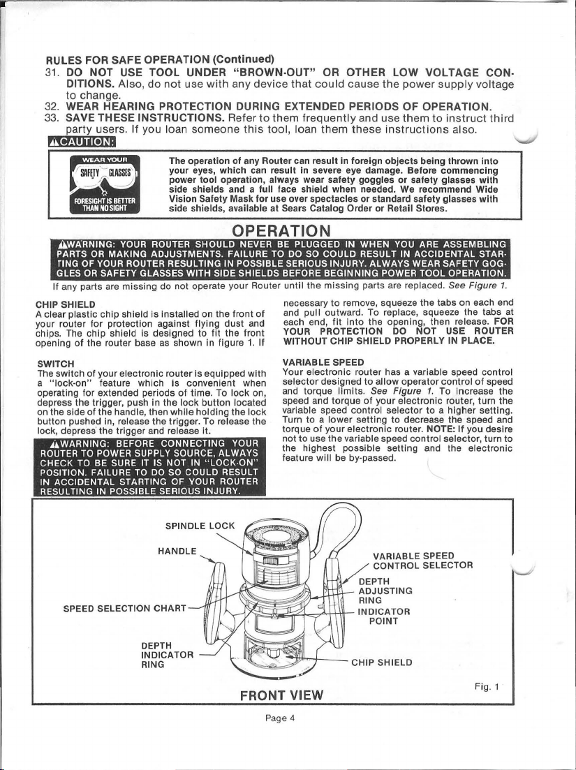
CHIP SHIELD
A clear plastic chip shield is installed on the front
your router
chips.
The
opening
of
SWITCH
The
switch
a
"Iock·on"
operating for extended periods
depress the trigger, push in the
on the side
button pushed in, release the trigger. To release
lock
, depress'
AWARNING
ROUTER
CHECK
TO
POSITION. FAILURE TO
IN
ACCIDENTAL STARTING OF
RESULTING
SPEED SELECTION CHART
YOUR
OR
MAKING ADJUSTMENTS. FAILURE
OF
YOUR
OR
SAFETY GLASSES WITH SIDE SHIELDS BEFORE BEGINNING POWER TOOL OPERATION.
for
protection against flying dust and
chip shield is designed to fit the
the
router base
of
your electronic router is equipped
feature which is convenient when
of
the
the
: BEFORE CONNECTING
TO POWER SUPPLY SOURCE, ALWAYS
BE
IN
ROUTER SHOULD NEVER BE PLUGGED IN WHEN
ROUTER RESULTING IN POSSIBLE SERIOUS INJURY. ALWAYS WEAR SAFETY
as
shown in figure
of
time. To
IT
IS
NOT
DO
SO
SPINDLE LOCK
HANDLE
lock
IN
COULD RESULT
YOUR
handle, then while holding the
trigger and release it.
SURE
POSSIBLE SERIOUS INJURY.
OPERATION
of
front
1.
If
with
lock on,
button located
" LOCK ·ON"
YOUR
ROUTER
lock
the
YOU
TO
DO
SO
COULD RESULT IN ACCIDENTAL STAR·
missing
parts are repla.ced. See Figure
necessary
and
each end,
YOUR PROTECTION
WITHOUT CHIP SHIELD
VARIABLE SPEED
Your electronic router has a variable speed control
selector
and torque limits.
speed and
variable speed control
Turn to a l
torque
not
the highest possible
feature
to
remove, squeeze
pull outward. To replace, squeeze the tabs at
fit
into
the opening, then release. FOR
designed to allow operator
of
your
to
use
the
will
__
-'+
See Figure
torque
of
your ele
ower
setting to decrease the speed and
electronic
variable speed control selector, turn to
be by· passed.
VARIABLE SPEED
CONTROL SELECTOR
t-\lt"- INDICATOR
POINT
ARE ASSEMBLING
GOG
the
tabs
on each end
DO
NOT USE ROUTER
PROPERLY
selector
router. NOTE: If you desire
setting
IN
PLACE.
control of
1.
To increase the
ctronic
router, turn the
to
a higher setti ng.
and the electronic
·
1.
speed
DEPTH
INDICATOR
RING
FRONT VIEW
Page 4
CHIP SHIELD
Fig. 1
Page 5
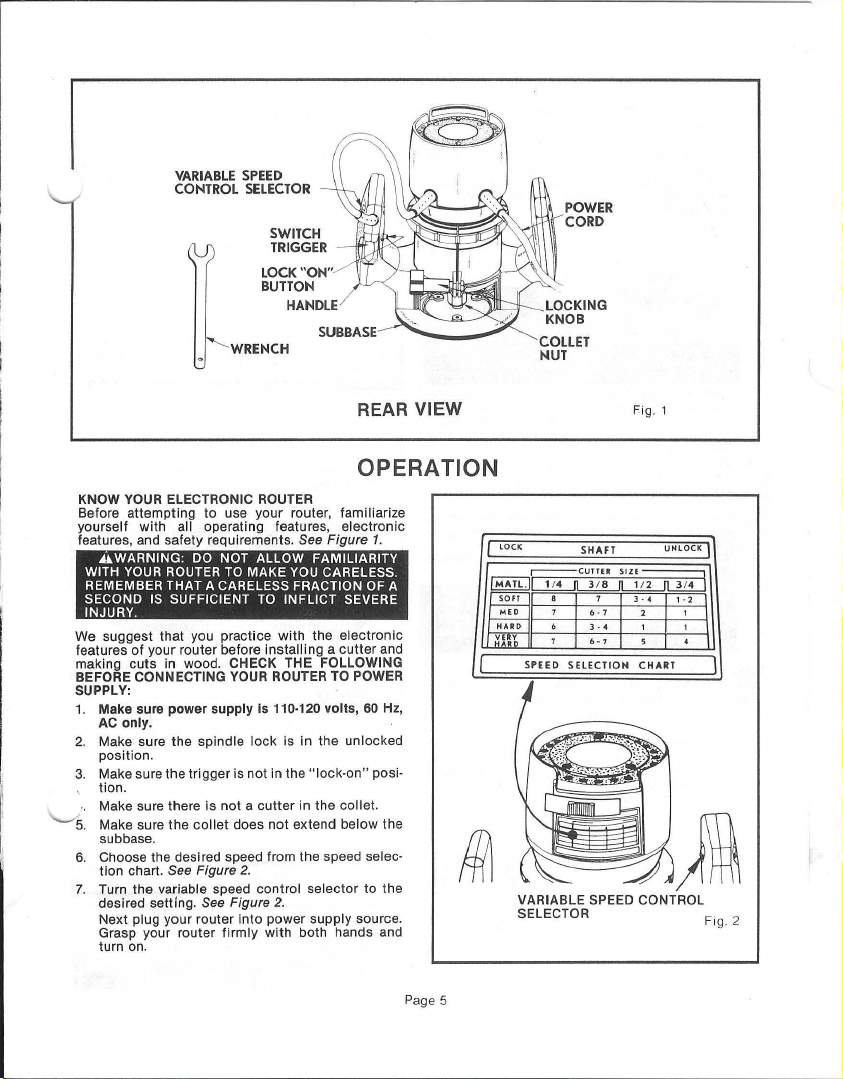
VARIABLE
CONTROL
SPEED
SELECTOR
SWITCH
TRIGGER
LOCK
BUTTON
"ON"
POWER
CORD
'--
WRENCH
SUBBASE
REAR VIEW
OPERATION
KNOW YOUR ELECTRONIC ROUTER
Before
attempting
yourself with
features, and
.... WARNING:
WITH
YOUR
REMEMBER THAT A CARELESS FRACTION OF A
SECOND
INJURY.
We suggest
features
of
making
cuts
BEFORE CONNECTING
SUPPLY:
1.
Make sure
AC
only.
2.
Make sure the
position.
3. Make sure
tion.
Make sure there is not a
5.
Make sure
subbase.
6. Choose the desi red speed from the speed selec·
tion
chart. See Figure
7.
Turn the variable speed
desired setting.
Next plug
Grasp your router
turn on .
to use
your
all operating features,
safety
requirements. See Figure
DO
NOT ALLOW FAMILIARITY
ROUTER
TO
IS
SUFFICIENT
that
you practice
your router before
in wood . CHECK THE FOLLOWING
power
supply Is 110·120 volts, 60 Hz,
spindle
the
trigger
the
collet
router, familiarize
MAKE
YOU
TO
INFLICT SEVERE
with
installing a cutter
YOUR
ROUTER TO POWER
lock
is in the
is not in the
cutter
does
in the collet.
not
extend below the
electronic
CARELESS.
the
electronic
unlocked
"Iock·on"
2.
control
selector
2.
power
supply
with
both hands and
source.
your
See Figure
router
into
firmly
to
1.
and
posi·
the
Fig. 1
LOCK
~~
SOfT
VARIABLE SPEED CONTROL
SELECTOR
r--CUTTER
SHAfT
.-
7
SIZE
3--4 '-2
UNLOCK
,
Fig. 2
Page 5
Page 6

INSTALLING/REMOVING CUTTERS
Disconnect
1. A spindle
2. Place your router upside
3. Remove
4.
5. Tighten the
DEPTH OF CUT ADJUSTMENTS
We recommend
ceeding
reach depths
Disconnect router from
justing
1.
2. Turn the depth
3.
4.
5.
router from
housing.
spindle
NEVER ATTEMPT
WHILE ROUTER MOTOR IS RUNNING OR
COASTING
turn
interlocks. See Fig. 3. NOTE:
spring
lock
CUTTER
CAREFUL
COLLET WITH YOUR
THEY WILL
HEAT
USE
clockwise
from collet. See Figure
to
diameter shank size.
With your router
sert shank
cutter
tom
clockwise
Put
wise the
lock
SHANKS WILL NOT TIGHTEN PROPERLY AND
COULD
INJURY.
Place the router
knob, and turn
Inside
touches
ring
point
Position the router so
below
Turn
desired depth
moves can be read on the depth
Each notch
1/64
Tighten
router.
lock
See
lock
collet
nut
loaded and
mechanism
.... WARNING: IF
BUILDUP FROM CUTTING. ALWAYS
THE WRENCH PROVIDED.
cutters
precision tolerances
should
of
collet.
spindle
interlocking
will
not let
~WARNING
UNDERSIZED
BE
1/8"
of
for
depth
subbase_ See Figure
flat surface. Turn the depth
until
the zero lines
on the base. See Figure
the subbase
the
inch change in
locking
power
is located on
Figure
in
and
TO
A STOP.
with wrench
interlocks
IMMEDIATELY
NOT TO TOUCH THE CUTTER
GET BURNED BECAUSE OF THE
enough
of
cutter
be
collet
with
the wrench provided. See Fig. 4 .
lock
back in
your
:
00
THROWN FROM TOOL CAUSING
that
cuts
and
that
cut
greater than
of
cut.
on a flat
depth
adjusting
depth
of
on
the depth
knob securely before operating
supply.
the
5.
slide
TO
ACTIVATE SPINDLE LOCK
will
snap
YOU
HANDS
by
turning
to
allow
4.
still
upside
into
collet. The shank
close
to
nut
mechanism
router tu
NOT
SHANKS.
be
several passes be made
power
adjusting
that
for
desired depth setting.
adjusting
cut. The
depth
front
To activate lock, push
into
lock
down
on a table, then
until
lock
mechanism
Spindle
into
position
.
ARE CHANGING A
AFTER USE, BE
OR FINGERS.
collet
nut
cutter
to
The
to
fit
but not
securely
unlock
USE
made at a depth
surface,
5.
ring
up
ring
distance
adjusting
setting.
slip
collet
is machined
cutters
down
on table, in·
touching
by
position.
of
the
rn
on.
CUTTERS WITH
UNDERSIZED
1/8"_
supply
before ad-
loosen
ring
until
until
tip
with
the
5.
the
bit
can extend
to
obtain
the
indicator
ring
OPERATION
of
motor
position.
lock
is
when
OR
counter
easily
with
1/4"
of
your
bot·
turning
Other-
spindle
\TOTIGHTEN
not
ex-
to
locking
cutter
of
cutter
indicator
indicator
cutter
indicates
INDICATOR
Is
POINT
the
ring.
~WARNING:
ING KNOB
DO
THIS WILL RESULT IN THE MOTOR MOVING
INSIDE
THIS COULD CAUSE LOSS OF CONTROL
RESULTING IN POSSIBLE SERIOUS INJURY.
Page 6
COLLET
NUT
.3
Fig
COLLET NUT
DEPTH
INDICATOR
RING
LOCKING
KNOB
DEPTH
ADJUSTING
RING
Fig
BE
ABSOLUTELY CERTAIN LOCK·
IS
FIRMLY TIGHTENED. FAILURE
THE BASE, CAUSING AN UNEVEN CUT.
.5
TO
Page 7

~"""~n":lI!'tTm.
ROUTING
See Figure
For ease
trol,
the router base. Grasp your router and hold it
with
and let
feed
what you are doing.
fatigued.
your
both
motor
cutter
6.
of
operation and
router has
hands
as
build
into
workpiece
maintaining
two
handles, one on each side
shown
in
to
Fig. 6. Turn router
its
full speed, then gradually
. Remain al
DO
NOT operate router when
ert
proper con-
and watch
OPERATION
,---
of
firmly
on
-
---------,
Fig.
6
SPEED SELECTION
In
general,
if
size is large,
1/8
slower speeds. When these
variable speed
speed
higher speeds than
when
RATE-OF-FEED
IMPORTANT:
speed
routing and edge shaping
set-up
proper rate
FORCE FEEDING
Clean,
done
per speed and is taking very small
tiny
move forward
slower than normal in relation
ment. As a result, the bit
revolves.
rougher finish.
power,
• becoming overloaded.
~
,------------------------~
the material being
or
"), then
cutting
only when the
, cleanly severed chips.
the depth of
your
electron ic
control
is
reached. NOTE: Carbide
steel
very hard materials.
In
for
for
smooth
which
addition
your
router, the
the
cut
to
of
feed.
routing and edge shaping can be
bit
too
fast, the
"Bigger
bites"
Bigger
could
TOO
FAST TOO SLOW
cut
is hard, the
cut
is
deep, (maximum
router
should
situations
selector
cutters
to selecting
"secret"
lies in making a careful
be
made and in
is
revolving at
If
your router is forced
RPM
must
mean
chips
result
exist, turn
until
cutters
and
should
to
selecting
or
bites
of
the
to
its
forward move-
take bigger
bigger
chips, and a
also require more
in
the
router
be run at
the desired
the
professional
near
to
bit
becomes
bites
Fig. 7
cutter
the
cut
be used
proper
the
its
pro-
produce
to
as
mot
or
Under extreme forcefeedi
.
RPM
of
the
bit
has to take so large knocked
splintering
at
Your Craftsman
tool (up
clean,
the overload
st
itutes "force
Bit size ,
Th
e larger the
slowly
wood is very hard, knotty,
operation
TOO SLOW FEEDING
is also possible to
It
forward too
work
wood fast enough
it
scrapes away sawdust-like particles. Scraping produces heat,
in
extreme cases, can even overheat the
destroy
In
addition, it is more
when the
practically no load on the
revolving
will
and
to
bounce
wood has a pronounced grain
areas).
ed
, instead
You can
sound of the
bit in
Pag
e 7
can become so sl
off
(rather than
and
gouging
to
25,000 rpm no-load speed), and
smooth
cuts
of
a forced (too fast) feed. What con-
-feeding" depends upon three things.
depth-of
bit
the router can
must
be slowed s
slowly. When
too
slowly
which
its
hardness .
bit
is scraping instead
close
to
have a much greater than normal
off
the sides
As a result
of
straight
detect
motor, or
the
cut.
ng
conditions
ow
that
fully
of
Electronic
if
allowed
-cut, and
workpiece
or
the deeper the cut , the more
be
moved forward. And,
spoil a cut
a revolving
to
take a bite; instead ,
can glaze, burn,
difficult
top
rpm
of
, the
cut
, sides. See Figure
"to
o-slow feeding" by the no-load
by feeling the
- and the
chips
will be partially
cut
off),
the workpiece. See
Router is a high-speed
to
run freely
characteristics.
gummy
till
mor
e.
by moving
it
is
advanced
bit
doesn't
or
mar
to
control a router
of
mot
or, the
for
the selected speed,
the
cut
(especially,
wit
h hard and
produced may have rippl-
"wiggle"
the relative
with
resul
will
or
damp, the
the
into
dig
into
it
the
bit
so as
cutting.
bit
tendency
7_
bites
ting
Fig. 7.
make
without
if
the
router
the
new
simply
cut
to
With
will
be
if
the
soft
of
the
it
Page 8

OPERATION
PROPER FEEDING
The right feed is neither
the rate at which the
surely to produce uniform chips into the wood to make
the other hand, to create
making a
wood, the proper feed may be about as fast as you
can
is a large one, the cut is deep, or the wood is hard to
cut, the proper feed may
again, a cross-grain cut may require a slower pace
than
workpiece.
Good judgement
tronic
experience
by feeling the progress
always test cut on a scrap
beforehand.
DEPTH
As previously mentioned, the depth
tant because it
affects the quality
of
requires a
deep cut will cause you to
that the
Making a deep cut is never
bits - especially those
- are easily broken
side thrust. A
but
and
bit as desired. For these reasons, we recommend
that you do
single pass, regardless
or
small diameter, shallow groove in
travel your router along your guide line. If the
an
identical cut with the grain
feature will give best results. You will learn by
...
by
OF CUT
affects
damage to your router
slower
bit
will
if
condition
large enough bit may not be broken
the cut is
it
may
be
very
not
of
the workpiece_ See Fig.
too
fast nor
bit
is
being advanced firmly and
large individual
only
be
with
the
proper use
listening
of
begin scraping instead
too
difficult
exceed
to
of
each cut. If at all possible,
of
the rate
a cut (and, also, the
motor
feed than a shallow one. A
slow
only
off
when subjected to too much
deep a rough cut will result -
to guide and control the
1/8
of
the
too
without
sawdust. If you are
a very slow one . Then,
in
the router
the workpiece wood,
of
cut is i mpor-
of
feed which, in turn,
and bit). A deep cut
the
feed so much
advisable_ The smaller
1/16
inch in diameter
inch depth
bit
size
or
the
slow. It is
hogging
chips
or, on
soft
the same
of
the Elec-
motor
possibility
of
cutting
of
cut
softness
8.
, dry
bit
and
too
.
off
in a
DIRECTION OF FEED AND THRUST
The router
tion. This gives the tool a
your hands) in a
Because
per
to contend
should the
ject, etc.
the
sufficient
not prepared.
tion
To guard against such a kickback,
and direction
thrusti
are using
that
the
sharp edges
into
ROUTING
See Figure 10.
Whenever you are routing a groove, your tool travel
should
you are using at the right-hand side. When the
is
travel should be
around curves. When the
,
shown in
should be right to
If there is a choice, the
easiest to use.
you see is against the guide.
motor
of
the
feeding"
operation, there is very
with
bit
that
cutting
action, there
to
spoil
Such a kickback is always
opposite
to
ng
the tool -
to
guide the cut - in the same
the
leading edge
thrust
should
of
new (uncut) wood.
be
in a
positioned
PASS
~
the
:
J'
as shown
and
bit
revolve
in a clockwise
slight
counterclockwise
high speed
under normal
strike a knot, hard grain, foreign ob-
wou
Id
affect
the
trueness
the
direction
of
feed so that you
to
be
the
bit
direction
left
to
second part
left
and .
In
either
tendency
direction
bit
rotation during a "pro-
little
conditions.
the normal progress
will
be a
slight
kickback -
of
your
cut
of
hold
it
agai nst whatever you
of
the
bit
in a
direction
continuously
that
places whatever guide
in
the
first
right and
guide
of
clockwlse
first
set-up is generally the
case, the sideways thrust
2ND.
PASS
in
bit
rotation.
plan your set·up
will
is moving.
that
biting
part
of
Fig.
counterclockwise
is
positioned
Fig.
10,
around curves .
MS
J
direc-
to
twist
.
kickba
However,
if
you are
the direc-
always be
direction
In
short,
keeps the
straight
guide
10,
tool
tool travel
(i"
ck
of
as
To make deeper
make as many successive passes as required, lowering the
bit
save time, do all the
setting, before loweri
will also assure a uniform depth when the final
This
pass is completed. See Fig.
cuts
it
is
therefore necessary
1/8
inch for each new pass.
cutting
necessary at one depth
ng
the
9.
bit
for
In
the
order
next pass.
to
to
Pag
e 8
GUIDE OUTSIDE
GUIDE INSIDE
Page 9

STARTING AND ENDING A CUT
INTERNAL ROUTING
Tilt
router and place on workpiece, letting edge
subbase contact workpiece first.
router
bit
'\
motor build to its full speed. Gradually feed
0
to
Upon coropletion
come
from work surface.
contact workpiece. Turn router on and let
workpiece until subbase is level
.... WARNING: KEEP A FIRM GRIP ON ROUTER
WITH BOTH HANDS
DO
SO
COULD RESULT
LEADING TO POSSIBLE SERIOUS INJURY.
to
a complete stop before removing router
A WARNING: NEVER PULL ROUTER OUT OF
WORK
AND PLACE UPSIDE DOWN
SURFACE BEFORE
ROTATING.
of
cut, turn
AT
Be
ALL
TIMES. FAILURE TO
IN
LOSS OF CONTROL
motor
THE
CUTTER STOPS
careful
with
off
ON
not
to let
cutter
workpiece.
and let
WORK
EDGE ROUTING
Place
router
on
of
bit
does not
let
motor
gradually feeding
in·
AWARNING
WITH BOTH HANDS
DO
SO
LEADING TO POSSIBLE SERIOUS INJURY.
Upon completion
come to a complete stop before removing router
it
from work surface.
AWARNING
WORK
SURFACE
ROTATING.
workpiece, making sure the router
contact
build
COULD RESULT
AND PLACE UPSIDE DOWN ON WORK
workpiece. Turn router on and
to
its full speed. Begin your cut,
cutter
into workpiece.
: KEEP A FIRM GRIP
AT ALL TIMES. FAILURE TO
IN
LOSS OF CONTROL
of
cut, turn
: NEVER PULL
BEFORE
motor
ROUTER
THE CUTTER STOPS
ON
off
ROUTER
and
let
OUT
OF
it
EDGING WITH
The arbor·type bits with
quick, easy edge shaping
is either straight or curved at a curvature
greater than the radius
prevents the
- holding the pilot firmly
edge throughout prevents the
too
shallow.
Whenever the workpiece
desired depth
ting) are such that only the top part
be shaped
tion
at
portion, which
However,
. too
low
THE PILOT BITS
bit
from making
of
cut
(leaving at least a 1
bottom), the pilot can ride against
will serve to guide it. See Fig.
if
the workpiece is
so
that there will be no uncut edge to ride the
pilots
are excellent for
of
any workpiece edge that
of
the bit
to
be
too
in
contact
thickness
(as
adjusted by router depth set·
ROUTER
deep a cut; and
with the workpiece
cut
from becoming
together
of
/16
in.
too
thin or the bit set
WOR~
c::=:
------~
----=
~&
~:::J'
TOP
EDGE
~
SHAPING
as
great
used. The
with
the edge is to
thick
uncut por·
the
PILOT
pilot
be placed under the wo rkpiece . This "guide" board
must have
or
curved
pilot
so
bit
the
Fig.
make less than a full
shape
the
NOTE: Any
pilot
size (diameter)
uncut
the maximum cut width that can be made with the
pilot against the workpiece edge (the small pilot' ex·
11.
poses all
amount
Page 9
against,
an
extra board to act as a guide
exactly the same contour - straight or
-
as
th~t
Will
other
the workpiece edge. If
its edge is flush with the workpiece edge, the
make a full cut (in
hand,
11
for
if
(out from the workpiece edge), the bit w ill
of
the finished edge.
of
the
edge shaping
of
the bit;
by
1/16
as
the guide is positioned
cut
piloted
bits can be used
with
of
inch) .
guides, as preceding. The
the
pilot
the
it
is positioned
far
as
the bit radius).
as
- which will alter the
that is used determines
large one reduces
JI
PILOT
&1:L
WHOLE
EDGE
SHAPING
must
shown
without
Fig.
On
in
this
11
a
Page 10

ROUTING WITH GUIDE BUSHINGS
When using the Template Guide Bushings Cat. No. 9-25082 with
cent er the bit with the bushing before beginning
the screws holding the subbase to
bu
shing.
After
in
~WARNING
CENTERING COULD CAUSE BIT TO COME IN CONTACT WITH BUSHING RESULTING
JURY.
EXTENSION CORDS
The use
of
power. To keep the loss
vent tool overheating,
sizes on the chart at right. When
doors, use only extension cords suitable for
use and so marked. Extension cords are available at
Sears Catalog Order
POWER CORD
See Figure 12.
Your router has a new extra·long 10' power cord
stays
soft
design
is
during use. A
cord storage easier.
THE FOLLOWING RECOMMENDED ACCESSORIES WERE AVAILABLE AT THE TIME THIS MANUAL WAS
PRINTED.
Dovetail Template
Box Joint
Butt Hinge Template
Butt Hinge
Router·Crafter
Multi·Purpose Router Guide
centering
:
FAILURE
of
any extension cord
follow
or
Retail Stores .
and flexible in cold weather. The plug
shaped so that
molded cord
Template(~
Template
(9
your
bit
with
TO
it
(9
2525C)
bushing
CENTER BIT WITH BUSHING
will
cause some loss
to a minimum
the recommended cord
tool
won't
snap on your work
clip
on
the
2579)
2580)
(~
2575)
(~
2564C)
(~
25179)
your
router.
Be
tighten
and
to
pre·
is used out·
outdoor
that
plug makes
cut. Your router subbase ma y
sure
locking
screws firmly.
Extension Cord Length
Template Guide
Rout-A·Form
Template Set
Sharpening
Carrying Case
Full View Router Base
your
Electronic
knob is securely
OR
TO FIRMLY TIGHTEN SCREWS AFTER
25·50 Feet
50·75 Feet
75·100 Feet
~
WARNING: CHECK EXTENSION CORDS
BEFORE EACH USE.
MEDIATELY.
ED
AREA
RESULTING IN SERIOUS INJURY.
NEVER USE TOOL WITH A DAMAG·
CORD SINCE TOUCHING THE DAMAGED
COULD CAUSE ELECTRICAL SHOCK
Bushings
Pantograph
(J.!.
2573)
Kit
(J.!.
(~
14701)
Router you
be
adju sted by loose ning
tightened before cent
IF
DAMAGED, REPLACE 1M·
(J.!.
25082)
(~
25183C)
66501)
(~
25086)
must
IN
SERIOUS IN.
Wire
visuall y
ering bit
Size A.W.
18
16
14
G.
'-.../
VEINING
BITS
CORE BOX
BIT FACE NATION
COMBI·
NATION
PANEL
cunER
~
25596- 1
12"
.
~
V-GROOVE
UBLE END
CHAMFER
S
2557-112"
' 25578
-1/2
~
25599-1/16"
2559- 1/8"
25592-3/ 16"
25593-7/32"
2554-1/
4"
25594.1/4"
'25541·3/8"
DO
2554545·,60·
V-GROOVE
""'!'III['l~AThe
STRAIGHT
2552-1
2552
2
25523-1/2"
255
'2
'25525-5
' 2
'25827-112
"
use of
5522-3/8"
5524-1/ 4"
5826-3/8
COMBI·
BITS STRAIGHT,
BEVEL
cunER
~
29-3
FO
R FORMICA
18"
'2541
1-1/4"
VENEE
CUTTER
/ 4"
STRAIGHT
' 25
/ 16"
"
BEVEL
"
'
attachments
~
2541
HINGE
MORTISING
BIT
~
R
1/2"
2555
41
3
2
or accessories
DOVETAIL RABBET OGEE COVE
cunER
2553-1
25531- 1
' CARBIDE TIPPED BITS
Page
10
BITS
!
/4"
12"
not
OJ
"'\0..
1/4,5/
25581
'2
listed above
BIT BIT
3/16"
25585
'W
"'\Qb
16.
ROMAN 0
3/
6"
25587-5/32
25588-1
5582
"
/4"
might
25572-3/8"
2557
'2
'25575-1
OJ
""\Qb
CHAMFER
BEAD
QUARTER·
ROUND
BITS
1-1
12"
5576
-3/8"
/2"
V
9:?b
45
·
25563-1/4"
25562-3/8"
BIT
25561-1/2"
'25566-3/8"
255B9
' 25565- 1/2"
be hazardous.
ARBOR I
25
89
i
lJ
m
W
ITH
2
BA
LL
BE
ARING S
(1
/2 & 5/8")
25895"
~
Page 11

MAINTENANCE
WHEN SERVICING
PROPER CARE OF CUTTERS
Get faster more accurate cutting results
cutters clean and sharp. Remove
itch and gum from cutters after each use.
Vhen
sharpening cutter, sharpen only the inside
the cutting edge. Never grind the outside diameter.
Be
sure when sharpening the end of a cutter
the clearance angle the same as originally ground.
A cutter sharpening kit (cat.
Sears Catalog
PROPER CARE OF COLLET
From time to time, it also becomes necessary
clean your collet and co
remove
chips that have
its original position.
SWITCH REPLACEMENT
Disconnect router from power supply.
SWITCH REPLACEMENT IS
1.
Remove screws
Figure
2.
NOTE THE LOCATIONS OF ALL WIRING
HANDLE AND HOW EACH LEAD IS CON·
NECTED TO
NUMBERS ON
SPEED CONTROL SWITCH .
wiring position must
new switch.
3.
Remove leads from switch
diameter pin or nail into switch lead receptacle
as shown
Remove nail or pin with a twisting,
tioo. .
4.
Make the lead connections
pushing each lead
receptacle in switch.
connections with lead receptacles.
5.
Locate switch
won't
cover
,
6.
Replace handle cover and screws.
7.
Tighten all screws securely.
Order or Retail Store.
collet nut from collet and clean the dust and
collected. Then return co llet nut
13.
THE
See
In
figure 14 and pulling
be
pinched or contact screws when handle
Is
replaced.
#66501)
llet
nut. To do so, simply
AS
(A)
THE
Figure
In
handle and place leads so they
FOLLOWS:
and handle cover (C). 5
SWITCH. ALSO
SIDE
OF
be
identical when installing
14.
by
to
as
far as possible into proper
Pull
on
USE
by
keeping
all accumulated
to
is
~vailable
IN
NOTE
THE
VARIABLE
Connections and
inserting a
on
the lead.
pulling mo-
the new switch by
leads
to
check lead
ONLY IDENTICAL REPLACEMENT
of
grind
from
to
to
~e
THE
THE
1/32"
PARTS
c
VARIABLE
SPEED .
SWITCH
CONTROL
Fig. 13
Fig.
14
LIGHT BULB REPLACEMENT
Disconnect router from power supply.
1.
Remove cutter from router. Adjust router
Imum
2. Remove screws
3.
4.
5.
height.
15.
Remove screw
With bulb pOinting toward you, push bulb
to
turn
Reassemble all parts.
Ihe left
(A)
and subbase
(C)
and work
10
remove.
light
(B).
See Figure
lens
(D).
to
max-
in
and
Page
11
Fig.
15
Page 12

GENERAL
iA.WARNING: ONLY THE PARTS SHOWN ON
PARTS LIST,
BE
CUSTOMER.
IMPORTANT PART OF THE DOUBLE INSULA·
TION
lY
BY
ClAN.
Avoid using solvents when cleaning plastic parts.
Most plastics are susceptible to various types
commercial solvents and may
use. Use clean
etc.
AWARNING: DO
FLUIDS, GASOLINE, PETROlEUM·BASED
DUCTS,
CONTACT WITH PLASTIC PARTS. THEY CON·
TAIN
WEAKEN,
PAGE FIFTEEN,
REPAIRED
SYSTEM AND SHOULD
A QUALIFIED SEARS SERVICE TECHNI·
PENETRATING
CHEMICALS
OR
All
OTHER PARTS REPRESENT
cloths
NOT AT ANY TIME
OR
DESTROY PLASTIC.
ARE
REPLACED
to
THAT
INTENDED
BY
BE
SERVICED ON·
be
damaged by
remove dirt, carbon dust,
lET
BRAKE
OilS,
ETC
. COME IN
CAN
DAMAGE
TO
THE
AN
their
PRO
HELPFUL HINTS
Always clamp workpiece securely before routing.
A safe operator is one who
Always wear eye protection when routi ng.
Make
set·up adjustments carefully. Then double check. Measure
Keep cutters clean and properly sharpened.
Don't let familiarity make you careless.
Study all safety rules
NEVER place your hands in jeopardy.
Make certain clamps can't loosen while in use.
Test
difficult
set·ups
Plan each operation before you begin.
THINK SAFETY
BY
thioks
ahead.
and
do the job safely.
on
scrap - Don't waste lumber.
THINKING AHEAD.
When electric
sports cars, etc .,
ject
to
failure,
highly
etc. Consequently
tool be used for extended work on any fiberglas
material. During any use on fiberglass
important
ing
with
of
GlES,
A DUST MASK BEFORE BEGINNING POWER TOOL
OPERATION
·
,
tools
are used on. fiberglass boats,
it
accelerated wear and possible premature
as
abrasive
an
SAFETY GLASSES WITH SIDE SHIELDS,
has been found
the fiberglass
to
bearings, brushes, commutators.
It is not recommended that thl
that
the tool Is cleaned frequently by
air jet. ALWAYS WEAR SAFETY GOG·
OR
BLOWING DUST.
twice
and cut once.
chips
that
and
grindings
It Is extremely
they
are sub·
are
blow
OR
·
Page
12
Page 13

NOTES
Page
13
Page 14

----
CRAFTSMAN ROUTER - M
ODEL NUMBER
3150174771,
23
14~
21~
~
20
Page 14
10
ti
<f727
Page 15

CRAFTSMAN ROUTER - MODEL NUMBER 315.174771
[G
The Model
mention
or
Number
will be
the Model
when ordering repair parts.
Number
found
on a plate
in all
correspondence
attached
to
the
End Cap. Always
regard in g
your
ROUTER
SEE BACK PAGE FOR PARTS ORDERING INSTRUCTIONS
Key
Part
No.
Number
1
989935·003
2 999701-001
3
967556·001
989652·004
4
5 989985·003
6 999603·
7
8 623166·004
9 990824·000
10
11
12
13
14
15
16
17
18
19
20
21
22
23
24
25
(-
26
27
28
29
30
NOTE: "A" - The assembly shown represents an important pari of the Double Insulated System. To avoid the possibility
· Standard Hardware Item -
··Available
001
612442·203
990822·002
610951 ·002
610930·001
606066·002
616081 ·013
623814·007
610946·
001
989684·001
612191·004
998586·
001
606688·001
999702·001
726676·002
611456·000
999498·001
612866·001
612839·001
623173·002
998116·009
998116·010
999605·001
612547·563
of alteration or damage to the
nearest Sears Catalog Order or Retail Store.
From Div. 98 - Source 980.00
Wrench.
Caution Label
Data Plate
De
pth
Adjust
Collet
Nut.
Locking
...... .
Base
'Square
Head
Po
wer Handle Ass
Variable Spe
Light Bulb (Standard
Light
Housing.
' Screw (#10·32 x
'
Scr
ew (#8·18 x 1/ 2 Pan Hd. T.C,) ' ' STD61080
Switch.
Work Light Len s
'Screw (#6·32
Subbase .....
'S
crew (#10·32 x 1/ 4 Pan Hd.).
Chip
Shield
Plate.
Logo
'S
et Screw (#8·
Handle Assemb
Speed Selection Chart .
'Ca
p Screw (#5·
tuator
Ac
Connector
Wire
Lead . . . . . . . . . . . . . . . . .
Lead. .
Spac
er.
Own er's
System, service should
May
Be Purchased Locally
PARTS LIST
Description
..........
Knob.
ed Control Selecto
x 1/ 4 Thread
..............
.
Manual
..
............
Ring and Indicator
.........
Bolt
("
'/4·20 x H/4) .........
embly
Automotive Bulb
. . .
11/16
Pan Head
..
................
32 x 7/16
ly.
40
x 1/ 4 So
..
. . • .
Assembly.
..
.......
. ..........
.
r.
)..................
Formin
g).
. ........ .
.
Hex Socket, Self Locking) ........
c.
Hd.).
......
.......
..
..
. . . . . .
be
performed by your nearest Sears Repair Center. Contact your
Page
15
. .
#100
. . . . •. . . •
.....•..
. .
4)
..
5.
. . . . . . .
. .
....
. . . . . • . .
.
.................
..
....
•.
.•...
...
..
.
. . . . .
Quantity
...
..
...
..
...
.
..
..
.
...
.
..
. . . . . 9
..
.
....
.....
..
...
.
..
......
...
.
..
...
..
. 1
1
1
1
1
. 1
1
. 1
1
1
. 1
1
1
4
1
1
. 1
. 1
3
1
. 1
1
1
. 1
1
2
2
1
Page 16

CRAFTSMAN
®
OWNERS
MANUAL
SERVICE
MODEL
315.174771
HOW
TO
REPAI
NO.
ORDER
R PARTS
ELECTR O
NIC
ROUTER
DOUBLE
Now
that
need ever
contact
Roebuck and C
nent facts whe n you
The model number of your Router will be found on
the
WHEN
THE
• PART
• MODEL
you ha
any Sears Service Center and
plate
attach~d
ORDERING
FOLLOW!~G
NUMBEF,l
315.174771
NUMBER
INSU
ve
exist
for repair parts
o.
stores.
to tDe
,
LA
TED
purchased
call
Be
or
your
Router, should a
or
sure
to
visit.
service,
provide all perti-
simply
most
.
motor
housing.
,fl
EPAIR PARTS, ALWAYS GIVE
INFORMATION:
• PART DESCRIPTION
• NAME OF ITEM
Router
Sears,
All parts listed may be ordered from any Sears Service Center and
If the parts you need are not stocked locally . your
order
will
Repair Parts
SEARS, ROEBUCK AND CO. , Dept. 6981731A. Sears Tower. Chicago. IL 60684
most
be
electronically
Distribution
Sears stores.
transmitted
Center
for
to
handlWlg.
'-..J
a Sears
 Loading...