

Page 1
OPERATOR'S MANUAL
T
3000 SERIES CHESTS & CABINETS
MODEL 31293 / 31295 MODEL 31292 / 31294
CALL 1-800-366-7278 FOR SERVICE PARTS. Refer to Service
Parts Drawing for full listingof Service Parts.
LOCATING MODEL # INFORMATION
Model numbers and other information required for service parts is
located on a label on the interior right side of the top most drawer.
• The maximum weight for each drawer should be no more than
50 Ibs.
• Empty weight of Model # 31293 is 55 Ibs.
• Empty weight of Model # 31295 is 96 Ibs.
• Empty weight of Model # 31292 is 58 Ibs.
• Empty weight of Model # 31294 is 114 Ibs.
• The maximum product weight for both models, including con-
tents, should be no more than 700 Ibs.
• For casters, use high quality bearing grease, (yearly).
• Lubricate the slides with grease or equivalent,(twice yearly.)
• Lubricate lock with graphite, (yearly).
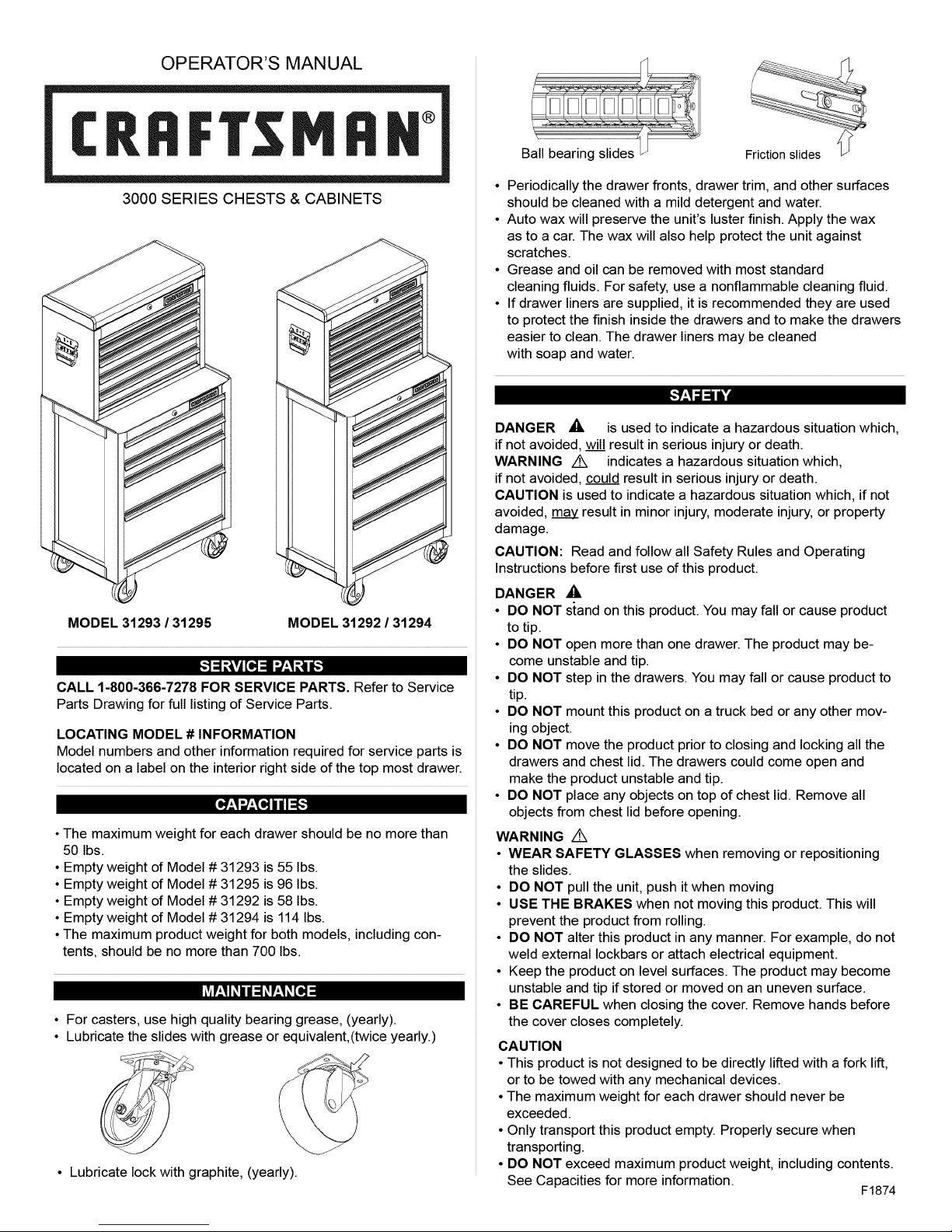
Ball bearing slides
• Periodically the drawer fronts, drawer trim, and other surfaces
should be cleaned with a mild detergent and water.
• Auto wax will preserve the unit's luster finish. Apply the wax
as to a car. The wax will also help protect the unit against
scratches.
• Grease and oil can be removed with most standard
cleaning fluids. For safety, use a nonflammable cleaning fluid.
• If drawer liners are supplied, it is recommended they are used
to protect the finish inside the drawers and to make the drawers
easier to clean. The drawer liners may be cleaned
with soap and water.
Friction slides
[-"Y-'_=1=l_
DANGER ,_, is used to indicate a hazardous situation which,
if not avoided, will result in serious injury or death.
WARNING z_ indicates a hazardous situation which,
if not avoided, could result in serious injury or death.
CAUTION is used to indicate a hazardous situation which, if not
avoided, may result in minor injury, moderate injury, or property
damage.
CAUTION: Read and follow all Safety Rules and Operating
Instructions before first use of this product.
DANGER ,_
• DO NOT s{and on this product. You may fall or cause product
to tip.
• DO NOT open more than one drawer. The product may be-
come unstable and tip.
• DO NOT step in the drawers. You may fall or cause product to
tip.
• DO NOT mount this product on a truck bed or any other mov-
ing object.
• DO NOT move the product prior to closing and locking all the
drawers and chest lid. The drawers could come open and
make the product unstable and tip.
• DO NOT place any objects on top of chest lid. Remove all
objects from chest lid before opening.
WARNING Z_
• WEAR SAFETY GLASSES when removing or repositioning
the slides.
• DO NOT pull the unit, push it when moving
• USE THE BRAKES when not moving this product. This will
prevent the product from rolling.
• DO NOT alter this product in any manner. For example, do not
weld external Iockbars or attach electrical equipment.
• Keep the product on level surfaces. The product may become
unstable and tip if stored or moved on an uneven surface.
• BE CAREFUL when closing the cover. Remove hands before
the cover closes completely.
CAUTION
• This product is not designed to be directly lifted with a fork lift,
or to be towed with any mechanical devices.
• The maximum weight for each drawer should never be
exceeded.
• Only transport this product empty. Properly secure when
transporting.
• DO NOT exceed maximum product weight, including contents.
See Capacities for more information.
F1874
Page 2
TOOLS REQUIRED: NOTE: Not all assembly instructions will relate to your model.
3/8-in Wrench
1/2-in Wrench
Cross-tip Screwdriver
HARDWARE INCLUDED:
CABINET HARDWARE
#14 - 10 x 5/8-in Hex Screws(Qty: 16)
(Qty: 4)
#14 - 10 x 3/4 Cross-tip Screw
CHEST HARDWARE
5/16 - 18 Ball Stud (Qty: 4)
5/16 - 18 Clip-on Nut (Qty: 4)
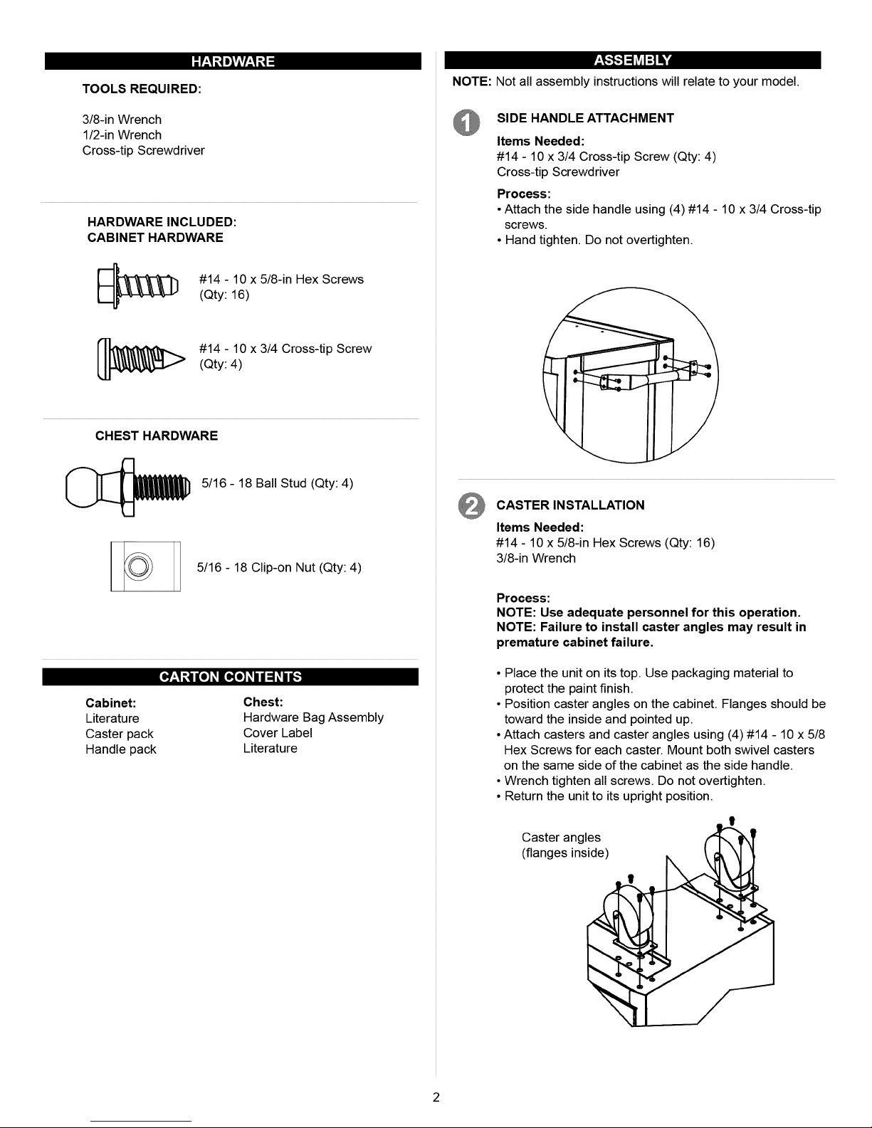
SIDE HANDLE ATTACHMENT
Items Needed:
#14 - 10 x 3/4 Cross-tip Screw (Qty: 4)
Cross-tip Screwdriver
Process:
• Attach the side handle using (4) #14 - 10 x 3/4 Cross-tip
screws.
• Hand tighten. Do not overtighten.
t
CASTER INSTALLATION
Items Needed:
#14 - 10 x 5/8-in Hex Screws (Qty: 16)
3/8-in Wrench
Process:
NOTE: Use adequate personnel for this operation.
NOTE: Failure to install caster angles may result in
premature cabinet failure.
Cabinet: Chest:
Literature Hardware Bag Assembly
Caster pack Cover Label
Handle pack Literature
• Place the unit on its top. Use packaging material to
protect the paint finish.
• Position caster angles on the cabinet. Flanges should be
toward the inside and pointed up.
• Attach casters and caster angles using (4) #14 - 10 x 5/8
Hex Screws for each caster. Mount both swivel casters
on the same side of the cabinet as the side handle.
• Wrench tighten all screws. Do not overtighten.
• Return the unit to its upright position.
Caster angles
(flanges inside)
Page 3
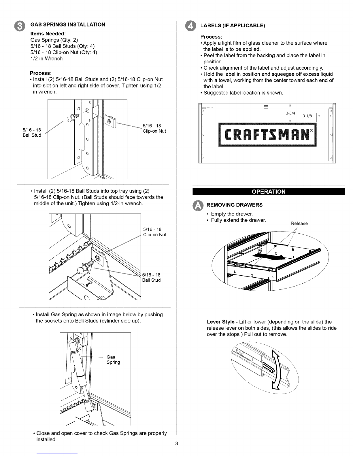
GAS SPRINGS INSTALLATION
Items Needed:
Gas Springs (Qty: 2)
5/16 - 18 Ball Studs (Qty: 4)
5/16 - 18 Clip-on Nut (Qty: 4)
1/2-in Wrench
Process:
• Install (2) 5/16-18 Ball Studs and (2) 5/16-18 Clip-on Nut
into slot on left and right side of cover. Tighten using 1/2-
in wrench.
LABELS (IF APPLICABLE)
Process:
• Apply a lightfilm of glass cleaner to the surface where
the label is to be applied.
• Peel the label from the backing and place the label in
position.
• Check alignment of the label and adjust accordingly.
• Hold the label in position and squeegee off excess liquid
with a towel, working from the center toward each end of
the label.
• Suggested label location is shown.
t
5/16 - 18
Ball Stud
....................5/16- 18
• Install (2) 5/16-18 Ball Studs into top tray using (2)
5/16-18 Clip-on Nut. (Ball Studs should face towards the
middle of the unit.) Tighten using 1/2-in wrench.
Clip-on Nut
5/16 - 18
Clip-on Nut
5/16 - 18
Ball Stud
[,]'-1 _1t,!:_li [,] l I
_ REMOVING DRAWERS
• Empty the drawer.
• Fully extend the drawer.
Release
• Install Gas Spring as shown in image below by pushing
the sockets onto Ball Studs (cylinder side up).
Gas
Spring
• Close and open cover to check Gas Springs are properly
installed.
Lever Style - Lift or lower (depending on the slide) the
release lever on both sides, (this allows the slides to ride
over the stops.) Pull out to remove.
3
Page 4

[,]_1_1_Z_li[,]_1
TabStyle-Depressthereleasetabsonbothsides,
(thisallowstheslidestorideoverthestops.)
Pullouttoremove.
FrictionStyle-Fullyextendthedrawer.Insertscrewdriver
intotheslotinthesideandpushinonthestopuntilit
clearsthelance.Pulldrawerjustpastlancebefore
releasingstop.Repeattheprocessfortheotherslide.
REMOVING AND INSTALLING SLIDES
• To remove the slide from the unit, first remove the
drawer.
• After removing the drawer check to see if the unit has
rivets located on the front of the slide. To drill out rivets,
use a 5/32-in drill bit. The rivets will need to be replaced
with 5/32-in rivets.
• Lift and hold the spring retainer and push the slide up-
ward. The slide may now be removed.
• To reinstall the slide in the appropriate position in the
unit, align front and back lances with mounting holes in
the side of the unit. Pull towards the front ofthe unit and
downwards until the spring retainer snaps into posi-
tion and secures the slide. The rivets will need to be
replaced with 5/32-in rivets.
• For smooth operation, make sure the drawers are
matched with their original slides.
Spring Retainer
_ INSTALLING DRAWERS
Ball bearing slide - Pull slides and slide carrier out to fully
extended position (see illustration.) Hold the slide on the
cabinet while aligning it with the slide on drawer. Slightly
insert one side and repeat for the other side. Slowly push
drawer to its fully closed position to engage slide. Open
drawer and reclose to ensure proper operation.
slidecarrier
/
/
slide
Page 5

MANUAL DE USUARIO
I:RRFTSMIIN°
SERIES 3000 CENTRO DE TRABAJO 135
CM CON 8 GAVETAS
Correderas de friccion
• Lubrique la cerradura con grafito (anualmente).
• Limpie con detergente suave y agua los frontales y los bordes laterales
de los cajones y las dem&s superficies.
• La cera para autom6viles preservar& el acabado brilloso de la unidad.
Aplique la cera como Io haria al carro. La cera tambien ayudar& a pro-
teger la unidad contra raspones.
• La grasa y el aceite pueden retirarse con la mayoria de los liquidos
est&ndar para limpieza. Por razones de seguridad, utilice un liquido
incombustible para limpieza.
• Si se suministran forros para las gavetas, se recomienda que se utilicen
para proteger el acabado interno de las mismas y para facilitar la limp-
ieza. Los forros para gavetas pueden limpiarse con agua y jab6n.
[.',]=[e'llJ_IJ7_,IJ]
PELIGRO _, se utiliza para indicar una situaci6n
peligrosa que, de no evitarse, resultar& en lesiones graves o la muerte.
ADVERTENClA ,,_ indica una situaci6n peligrosa que, de no
evitarse, podria producir lesiones graves o la muerte.
PRECAUClON se utiliza para indicar una situaci6n peligrosa que, de
no evitarse, puede derivar en lesiones leves o moderadas, o en daSo a la
propiedad.
ATENClON: Lea y siga todas las Normas de Seguridad y las
Instrucciones de Funcionamiento antes de utilizar por primera vez este producto.
MODELO NO. 31293 / 31295 MODELO NO. 31292 / 31294
"-]I=!._'_,%11J]=[,."]=1=_vj[=][e]
EN ESTADOS UNIDOS LLAME AL 1-800-659-7084 PARA
PIEZAS DE REPUESTO. FUERA DE ESTADOS UNIDOS
LLAME A SU DISTRIBUlDOR LOCAL. Suministre el nQmerode
modelo alcomunicarse.
UBICAClON DE INFORMAClON DEL NO. DE MODELO
El nQmerode modelo y demos informaci6nrequerida para laspiezasde
servicio se encuentran en unaetiqueta en ellado interior derecho de la
gaveta superior.
[_7-'I_2-'_]IJ7-'IJ]
El 3eso m&ximo en cada gaveta no debe ser mayor de 22,7 kg.
El 3eso vacio de la unidad Modelo 31293 es 25 kg.
El 3eso vacio de la unidad Modelo 31295 es 43,6 kg.
El 3eso vacio de la unidad Modelo 31292 es 26,4 kg.
El 3eso vacio de la unidad Modelo 31294 es 51,8 kg.
El 3eso m&ximo del producto para ambos modelos, incluyendo su con-
tenido, no debe ser mayor de 318,2 kg.
i_vlr:1_// :1_1hV41:1_/ lie]
• Para las ruedas, utilice grasa para rodamientos de alta calidad
(anualmente).
• Lubrique las guias con grasa o equivalente (dos veces por aSo).
PELIGRO _,
• NO se ponga de pie sobre esta unidad. Puede caerse u ocasionar que
el producto se vuelque.
• NO abra m&s de una gaveta. El producto podria quedar inestable y
volcarse.
• NO utilice las gavetas como peldaSos. Puede caerse u ocasionar que
el producto se vuelque.
• NO monte este producto en una cama de carro o ninguln otro objeto
m6vil.
• NO mueva la unidad antes de cerrar y asegurar todas las gavetas y
la tapa del baQI. Las gavetas podrian abrirse y hacer que la unidad se
vuelva inestable y se vuelque.
• NO coloques ningen objeto sobre la tapa del baQI. Quita todos los obje-
tos de la tapa del baQI antes de abrirlo.
ADVERTENClA Z_
• USE GAFAS DE SEGURIDAD al quitar o volver a poner las
correderas.
• NO hale la unidad, empQjela cuando la mueva.
• UTILICE LOS FRENOS cuando el producto no este en movimiento.
Esto impedir& que se deslice.
• NO altere la unidad en modo alguno. Por ejemplo, no suelde las barras
de sujeci6n externas ni le incorpore equipos electricos.
• Mantenga la unidad en superficies niveladas. La unidad puede tornarse
inestable y volcarse si se almacena o se moviliza en una superficie no
nivelada.
• TENGA cuidado cuando cierre la tapa. Quite las manos antes de que la
tapa cierre completamente.
PRECAUCION
• Este producto no est& dise_ado para ser levantado directamente con un
montacargas, ni para ser remolcado con unidades mecanizadas.
• Nunca debe exceder el peso m&ximo de cada gaveta.
• $61o transporte esta unidad cuando este vacia. AsegQrela
adecuadamente cuando la transporte.
• NO exceda el peso m&ximo del producto, incluyendo el contenido.
Refierase alas Capacidades para m&s informaci6n.
F1874
Page 6

HERRAMIENTAS NECESARIAS:
NOTA: No todas las instrucciones de ensamblaje se refieren a tu modelo.
Llave Inglesa de 3/8 inch
Llave Inglesa de 1/2 inch
Destornillador de Punta en Cruz
PIEZAS INCLUIDAS:
GABINETE DE HARDWARE
(Cant: 16)
Tornillo Hexagonal de No. 14 - 10 x 5/8
(Cant: 4)
Tuerca Phillips de No. 14 - 10 x 3/4
BAUL DE HARDWARE
[__ Perno Esfericode 5/16 - 18 (Cant: 4)
INSTALACION DE LA MANIJA LATERAL
Elementos necesarios:
TornillosPhillipsde No.14 - 10x 3/4 (Cant.:4)
Destornillador de Puntaen Cruz
Proceso:
• Fije la manija lateral usando 4 tornillos de Punta en Cruz de
No. 14- 10 x 3/4.
• Apriete a mano. No apriete demasiado.
t
INSTALACION DEL TIRADOR
Tuerca de Abrazadera de 5/16 - 18(Cant: 4)
[_o]_i i :1_11JIo_IJ]:111:To_:IY:IIII: [o_:I_31L'_]_I
Gabinete:
Material impreso
Paquete de ruedas
Paquete de Manijas
Baul:
Hardware y Asamblea de Bolso
Etiqueta de Cubierta
Literatura
Elementos necesarios:
Tornillo Hexagonal de No. 14 - 10 x 5/8 (Cant.: 16)
Llave Allen de 3/8 pig
NOTA: Utilice personal adecuado para esta operacion.
NOTA: No instalar los angulos de las ruedas giratorias
puede ocasionar falla prematura del gabinete.
• Coloque la unidad sobre su parte superior. Utilice el material de
empaque para protegaer el acabado de la pintura.
• Ubique los &ngulos de las ruedas giratorias en el gabinete. Las
pestaSas deben ir hacia el interior y apuntando hacia arriba.
• Fije las ruedas giratorias y los &ngulos de las ruedas giratorias
utilizando (4) tornillos hexagonal No. 14 - 10 x 5/8 para cada
rueda giratoria. Monte ambas ruedas pivotantes en el mismo lado
del gabinete donde se encuentra la manija lateral.
• Apriete todos los tornillos con una Ilave. No apriete demasiado.
• Vuelva a colocar la unidad en su posici6n vertical.
|
Angulos de ruedas giratoriea
(pestanas hacia adentro)
Page 7

INSTALACION DE PRIMAVERAS DE GAS
Elementos necesarios:
Amortiguador neum&ticoes (Cant: 2)
Perno Esferico de 5/16 - 18 (Cant: 4)
Tuerca de Abrazadera de 5/16 - 18 (Cant: 4)
Llave Allen de 1/4 pig
Proceso:
• Instala (2) Pernos Esfericos de 5/16 - 18 y (2) Tuercas de
Abrazadera de 5/16 - 18 en la ranura de los lados derecho e
izquierdo de la cubierta. Ajusta con una Ilave Allen de 1/2 pig.
Ajusta con una Ilave Allen de 1/2 pig.
ETIQUETAS (SI APLICA)
Proceso:
• Aplica una capa fina de limpiador para vidrios en la superficie
donde se colocar& la etiqueta.
• Quite el revestimiento de la etiqueta y col6quela en su sitio.
• Revise el alineamiento de la etiqueta y ajQstelo segQn sea
necesario.
• Sostenga la etiqueta en su lugar y elimine el exceso de liquido
con una toalla, empujando desde el centro hacia cada extremo
de la etiqueta.
Perno
Esferico de
5/16-18
• Instala (2) Pernos Esfericos de 5/16 -18 en la bandeja supe-
rior con (2)Tuercas de Abrazadera de 5/16 - 18. (Los Pernos
Esfericos deben quedar de frente al centro de la unidad). Ajusta
con una Ilave Allen de 1/2 pig.
........._.r,...,._..,.Tuerca de
Clip 5/16-18
_ REMOCl6N DE GAVETAS
• Vacie la gaveta.
• Abra completamente la gaveta.
Libere
Tuerca de
Clip 5/16-18
Perno
Esferico de
5/16-18
• Instala el Amortiguador Neum&tico como se muestra en la
siguiente ilustraci6n empujando los casquillos en los Pernos
Esfericos (con el cilindro hacia arriba).
Amortiguador
• Cierra y abre la cubierta para comprobar que los Amortigua-
dores esten instalados correctamente.
Estilo palanca - Levante o baje (dependiendo de la corredera)
la palanca de liberaci6n en ambos lados (esto permite que las
correderas pasen sobre los topes.) Jale hacia afuera para retirar.
Page 8

Estilo lengUeta - Oprima las lengQetas de liberaci6n en ambos
lados (esto permite que las correderas pasen sobre los topes.)
Jale hacia afuera para retirar.
INSTALACION Y DESINSTALCION DE CORREDERAS
• Para quitar la corredera de la unidad, primero quite la gaveta.
• Despues de quitar el caj6n, comprueba si la unidad tiene
remaches en el frente de la corredera. Para quitar los remaches
con untaladro, usa una broca para taladro de 5/32 pig. Deber_s
reemplazar los remaches con remaches de 5/32 pig.
• Levanta y sosten el reten del resorte y empuja la corredera
hacia arriba. Ahora puedes quitar la corredera.
• Para volver a instalar correctamente la corredera en la unidad,
alinea las lancetas frontales y posteriores con los orificios de
montaje en el lado de la unidad. Hala hacia adelante la unidad y
hacia abajo hasta que el reten del resorte encaje en su posici6n
y fije la corredera. Deber_s reemplazar los remaches con unos
de 5/32 pig.
• Para la operaci6n lisa, cerci6rese de que los cajones esten cor-
respondidos con con sus diapositivas originales.
Estilo friction - extienda completamente la gaveta. Inserte el
destornillador en la ranura del costado y presione el tope hasta
que libere el rej6n. Hale la gaveta justo despues del rej6n antes
de liberar el tope. Repita el proceso con la otra corredera
INSTALAClON DE GAVETAS
Correderas de rodamientos esfericos - hale hacia afuera
las correderas y el soporte de las correderas hasta que queden
en posici6n totalmente extendida (ver ilustraci6n). Sostenga la
corredera en el gabinete mientras Io alinea con la corredera de la
gaveta.
Soporte de las correderas
Reten flexible
Corredera
 Loading...