

Page 1
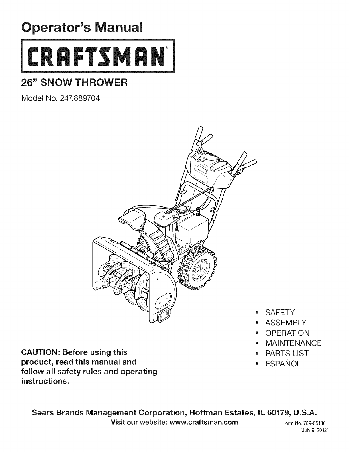
Operator's Manual
CRRFr MRN
26" SNOW THROWER
Model No. 247.889704
\
CAUTION" Before using this
product, read this manual and
follow all safety rules and operating
instructions.
Sears Brands Management Corporation, Hoffman Estates, IL 60179, U.S.A.
Visit our website: www.craftsman.com FormNo. 769-05136F
,, SAFETY
o ASSEMBLY
OPERATION
MAINTENANCE
PARTS LIST
o ESPANOL
(July9,2012)
Page 2
WarrantyStatement.................... Page2
SafeOperationPractices.............. Pages3-6
Assembly......................... Pages8-13
Operation........................ Pages14-17
Service&Maintenance.............. Pages18-25
Off-SeasonStorage................... Page26
Troubleshooting...................... Page27
PartsList......................... Pages28-45
RepairProtectionAgreement............ Page49
Espadol............................. Page50
CRAFTSMANTWOYEARFULLWARRANTY
FORTWOYEARSfromthedateofpurchase,thisproductiswarrantedagainstanydefectsinmaterialorworkmanship.Defectiveproductwill
receivefreerepairorfreereplacementifrepairisunavailable.
ADDiTiONAL LiFETiME LiMiTED WARRANTY on UPPER and LOWER CHUTE
FORAS LONGAS ITISUSEDbythe originalownerafterthe secondyearfromthedateof purchase,theupperandlowerchuteofthissnow
throwerarewarrantedagainstanydefectsinmaterialorworkmanshipas verifiedby a Searsauthorizedserviceprovider.Withproofofpurchase,
youwill receiveanewchutefree of charge.Youare responsibleforthelaborcostofinstallationandanycostincurredtoverifythedefect.
Forwarrantycoveragedetailsto obtainrepairor replacement,visitthewebsite:www.craftsman.com
ThiswarrantycoversONLYdefectsin materialandworkmanship.Warrantycoveragedoes NOTinclude:
• Expendableitemsthatcanwearoutfromnormalusewithinthewarrantyperiod,includingbutnotlimitedtoaugers,augerpaddles,drift
cutters,skidshoes,shaveplate,shearpins,sparkplug,air cleaner,belts,andoil filter.
• Standardmaintenanceservicing,oilchanges,ortune-ups.
Tirereplacementor repaircausedbypuncturesfromoutsideobjects,suchasnails,thorns,stumps,orglass.
• Tireor wheelreplacementor repairresultingfromnormalwear,accident,orimproperoperationormaintenance.
Repairsnecessarybecauseof operatorabuse,includingbutnot limitedto damagecausedbyover-speedingtheengine,orfromimpacting
objectsthatbendtheframe,augershaft,etc.
• Repairsnecessarybecauseof operatornegligence,includingbutnotlimitedto,electricalandmechanicaldamagecausedby improper
storage,failureto usethepropergradeandamountofengineoil,or failureto maintaintheequipmentaccordingtotheinstructionscontained
intheoperator'smanual.
• Engine(fuelsystem)cleaningor repairscausedbyfueldeterminedto becontaminatedoroxidized(stale).in general,fuelshouldbeused
within30 daysof itspurchasedate.
Normaldeteriorationandwearoftheexteriorfinishes,or productlabelreplacement.
Thiswarrantyisvoid if thisproductiseverusedwhileprovidingcommercialservicesor if rentedtoanotherperson.
Thiswarrantygivesyouspecificlegalrights,andyou mayalso haveotherrightswhichvaryfromstatetostate.
Sears Brands Management Corporation, Hoffman Estates, IL 60179
EngineOilType: 5W-30
EngineOilCapacity: 20ounces
FuelCapacity: 2 Quarts
SparkPlug: F6RTC(951-10292)
SparkPlugGap: .020"to .030"
©SearsBrands,LLC
ModelNumber.................................................................
Serial Number.................................................................
Dateof Purchase.............................................................
Recordthemodelnumber,serialnumber
anddateof purchaseabove
2
Page 3

Thissymbolpointsoutimportantsafetyinstructionswhich,if not
followed,couldendangerthepersonalsafetyand/orpropertyof
yourselfandothers. Readandfollowall instructionsin thismanual
beforeattemptingto operatethismachine.Failureto complywith
theseinstructionsmayresultin personalinjury.Whenyouseethis
symbol,HEEDITSWARNING!
Thismachinewasbuilttobeoperatedaccordingtothesafeopera-
tionpracticesinthis manual.Aswithanytypeof powerequipment,
carelessnessorerroron thepartoftheoperatorcanresultin serious
injury.Thismachineiscapableofamputatingfingers,hands,toes
andfeetandthrowingdebris.Failuretoobservethefollowingsafety
instructionscouldresultin seriousinjuryor death.
CALIFORNIA PROPOSITION 65
EngineExhaust,someof itsconstituents,andcertainvehicle
componentscontainoremitchemicalsknowntoStateofCalifornia
tocausecancerandbirthdefectsorotherreproductiveharm,
TRAiNiNG
• Read,understand,andfollowall instructionson themachineand
in themanual(s)beforeattemptingtoassembleandoperate.
Failuretodo socan resultinseriousinjurytotheoperatorand/
orbystanders.Keepthismanualina safeplaceforfutureand
regularreferenceandfor orderingreplacementparts.
• Befamiliarwithall controlsandtheirproperoperation.Knowhow
tostopthemachineanddisengagethemquickly.
• Neverallowchildrenunder14yearsofagetooperatethis
machine.Children14andover shouldreadandunderstandthe
instructionsandsafeoperationpracticesin thismanualandon
themachineandbe trainedandsupervisedbyanadult.
Neverallowadultsto operatethis machinewithoutproper
instruction.
• Thrownobjectscancauseseriouspersonalinjury.Planyour
snow-throwingpatterntoavoiddischargeof materialtoward
roads,bystandersandthe like.
Keepbystanders,petsandchildrenat least75feetfromthe
machinewhileitisin operation.Stopmachineif anyoneenters
thearea.
• Exercisecautiontoavoidslippingor falling,especiallywhen
operatinginreverse.
Your Responsibility--Restrict theuseofthispowermachineto
personswhoread,understandandfollowthewarningsand instruc-
tionsin thismanualandon themachine,
SAVE THESE INSTRUCTIONS!
PREPARATION
Thoroughlyinspecttheareawheretheequipmentistobeused.
Removeall doormats,newspapers,sleds,boards,wiresandother
foreignobjects,whichcouldbe trippedoverorthrownbytheauger/
impeller.
• Alwayswearsafetyglassesoreyeshieldsduringoperationand
whileperformingan adjustmentor repairto protectyoureyes.
Thrownobjectswhichricochetcancauseseriousinjurytothe
eyes.
Donot operatewithoutwearingadequatewinteroutergarments.
Donot wearjewelry,longscarvesorotherlooseclothing,which
couldbecomeentangledinmovingparts.Wearfootwearwhich
willimprovefootingonslipperysurfaces.
Usea groundedthree-wireextensioncordand receptacleforall
machineswithelectricstartengines.
Disengageall controlleversbeforestartingtheengine.
Adjustcollectorhousingheighttocleargravelorcrushedrock
surfaces.
• Neverattempttomakeanyadjustmentswhileengineis running,
exceptwherespecificallyrecommendedintheoperator'smanual.
Letengineandmachineadjusttooutdoortemperaturebefore
startingtoclearsnow.
3
Page 4
SafeHandlingof Gasoline
Toavoidpersonalinjuryor propertydamageuseextremecarein
handlinggasoline.Gasolineisextremelyflammableandthevaporsare
explosive.Seriouspersonalinjurycanoccurwhengasolineis spilled
onyourselforyourclotheswhichcan ignite. Washyourskinand
changeclothesimmediately.
• Useonlyan approvedgasolinecontainer.
• Extinguishallcigarettes,cigars,pipesandothersourcesof
ignition.
• Neverfuel machineindoors.
• Neverremovegascapor addfuelwhilethe engineis hot or
running.
• Allowenginetocoolat leasttwo minutesbeforerefueling.
• Neveroverfillfueltank.Filltankto nomorethan1/2inchbelow
bottomoffillerneckto providespaceforfuelexpansion.
• Replacegasolinecapandtightensecurely.
• Ifgasolineis spilled,wipe it off theengineandequipment.Move
machinetoanotherarea.Wait5 minutesbeforestartingthe
engine.
• Neverstorethe machineorfuelcontainerinsidewherethereisan
openflame,sparkor pilotlight(e.g.furnace,waterheater,space
heater,clothesdryeretc.).
• Allowmachineto cool at least5 minutesbeforestoring.
• Neverfill containersinsideavehicleor ona truckor trailerbed
witha plasticliner.Alwaysplacecontainersonthegroundaway
fromyourvehiclebeforefilling.
• If possible,removegas-poweredequipmentfromthe truckor
trailerandrefuelit ontheground.Ifthis is not possible,thenrefuel
suchequipmenton atrailerwitha portablecontainer,ratherthan
froma gasolinedispensernozzle.
• Keepthe nozzlein contactwiththerimofthefueltankor
containeropeningatalltimes untilfuelingiscomplete.Do not use
a nozzlelock-opendevice.
OPERATION
• Do not puthandsorfeetnearrotatingparts,intheauger/impeller
housingorchuteassembly.Contactwiththerotatingpartscan
amputatehandsandfeet.
• Theauger/impellercontrolleveris a safetydevice.Neverbypass
itsoperation.Doingsomakesthemachineunsafeandmaycause
personalinjury.
• Thecontrolleversmustoperateeasilyinbothdirectionsand
automaticallyreturntothedisengagedpositionwhenreleased.
• Neveroperatewitha missingor damagedchuteassembly.Keep
all safetydevicesin placeandworking.
• Neverrunanengineindoorsor ina poorlyventilatedarea. Engine
exhaustcontainscarbonmonoxide,anodorlessanddeadlygas.
• Do notoperatemachinewhileunderthe influenceofalcoholor
drugs.
• Mufflerandenginebecomehotandcancauseaburn.Donot
touch.Keepchildrenaway.
• Exerciseextremecautionwhenoperatingon orcrossinggravel
surfaces.Stayalertforhiddenhazardsortraffic.
Exercisecautionwhenchangingdirectionandwhileoperatingon
slopes.Do notoperateonsteepslopes.
Planyoursnow-throwingpatternto avoiddischargetowards
windows,walls,carsetc.Thus,avoidingpossibleproperty
damageorpersonalinjurycausedbya ricochet.
Neverdirectdischargeatchildren,bystandersand petsorallow
anyoneinfrontofthemachine.
Donot overloadmachinecapacitybyattemptingto clearsnowat
toofastof a rate.
Neveroperatethismachinewithoutgoodvisibilityorlight.Always
be sureofyourfootingand keepa firmholdon thehandles.Walk,
neverrun.
Disengagepowerto theauger/impellerwhentransportingor not
in use.
Neveroperatemachineathightransportspeedsonslippery
surfaces.Lookdownand behindand usecarewhenbackingup.
Ifthemachineshouldstartto vibrateabnormally,stoptheengine,
disconnectthesparkplugwire andgrounditagainsttheengine.
Inspectthoroughlyfor damage.Repairanydamagebefore
startingandoperating.
Disengageall controlleversandstopenginebeforeyouleave
theoperatingposition(behindthehandles).Waituntilthe auger/
impellercomestoa completestopbeforeuncloggingthechute
assembly,makingany adjustments,or inspections.
Neverputyourhandinthedischargeor collectoropenings.Do
notunclogchuteassemblywhileengineisrunning.Shutoff
engineand remainbehindhandlesuntilall movingpartshave
stoppedbeforeunclogging.
Useonlyattachmentsandaccessoriesapprovedbythemanufac-
turer(e.g.wheelweights,tirechains,cabsetc.). Forinformation
concerningtheseitems,call 1-800-469-4663.
Whenstartingengine,pullcordslowlyuntilresistanceisfelt,then
pull rapidly.Rapidretractionofstartercord(kickback)willpull
handandarmtowardenginefasterthanyoucan let go. Broken
bones,fractures,bruisesorsprainscouldresult.
Ifsituationsoccurwhichare notcoveredinthismanual,usecare
andgoodjudgment.
Toorderpartsor scheduleservicefor thisproduct,call 1-800-
469-4663.
CLEARING A CLOGGED DISCHARGE CHUTE
Handcontactwiththe rotatingimpellerinsidethedischargechute
is themostcommoncauseofinjuryassociatedwithsnowthrowers.
Neveruseyourhandtocleanoutthedischargechute.
Toclear thechute:
1. SHUTTHEENGINEOFF!
2. Wait 10secondsto be surethe impellerbladeshavestopped
rotating.
3. Alwaysusea clean-outtool,not yourhands.
4
Page 5
MAINTENANCE & STORAGE
• Nevertamperwithsafetydevices.Checktheirproperoperation
regularly.Refertothemaintenanceandadjustmentsectionsof
thismanual.
• Beforecleaning,repairing,or inspectingmachinedisengageall
controlleversandstopthe engine.Waituntiltheauger/impeller
cometoa completestop.Disconnectthe sparkplugwireand
groundagainsttheenginetopreventunintendedstarting.
Checkboltsand screwsforpropertightnessatfrequentintervals
tokeepthe machineinsafeworkingcondition.Also,visually
inspectmachineforanydamage.
Donotchangetheenginegovernorsettingorover-speedthe
engine.Thegovernorcontrolsthe maximumsafeoperatingspeed
oftheengine.
Snowthrowershaveplatesandskidshoesaresubjecttowear
anddamage.Foryoursafetyprotection,frequentlycheckall
componentsand replacewithoriginalequipmentmanufacturer's
(OEM)partsonlyas listedinthe Partspagesof thisoperator's
manual.Useofpartswhichdonotmeettheoriginalequipment
specificationsmayleadto improperperformanceandcompro-
misesafety!
Checkcontrolleversperiodicallytoverifytheyengageanddisen-
gageproperlyandadjust,if necessary.Refertotheadjustment
sectioninthisoperator'smanualforinstructions.
Maintainor replacesafetyandinstructionlabels,asnecessary.
Observeproperdisposallawsand regulationsfor gas,oil,etc. to
protecttheenvironment.
Priorto storing,runmachineafew minutestoclearsnowfrom
machineand preventfreezeupofauger/impeller.
Neverstorethemachineorfuelcontainerinsidewherethereisan
openflame,sparkorpilotlightsuchas a waterheater,furnace,
clothesdryeretc.
Alwaysrefertotheoperator'smanualforproperinstructionson
off-seasonstorage.
Checkfuelline,tank,cap,andfittingsfrequentlyforcracksor
leaks.Replaceif necessary.
Donotcrankenginewithsparkplugremoved.
AccordingtotheConsumerProductsSafetyCommission(CPSC)
andtheU.S.EnvironmentalProtectionAgency(EPA),thisproduct
hasan AverageUsefulLifeof seven(7)years,or60 hoursof
operation.Attheendof theAverageUsefulLifehavethe machine
inspectedannuallybyan authorizedservicedealerto ensurethat
allmechanicalandsafetysystemsareworkingproperlyandnot
wornexcessively.Failuretodo so can resultinaccidents,injuries
ordeath.
DO NOT MODIFY ENGINE
Toavoidseriousinjuryor death,do notmodifyengineinanyway.
Tamperingwiththegovernorsettingcanleadtoa runawayengineand
causeittooperateat unsafespeeds.Nevertamperwithfactorysetting
ofenginegovernor.
NOTICE REGARDING EMiSSiONS
EngineswhicharecertifiedtocomplywithCaliforniaandfederal
EPAemissionregulationsforSORE(SmallOff RoadEquipment)are
certifiedto operateon regularunleadedgasoline,and mayinclude
thefollowingemissioncontrolsystems:EngineModification(EM),
OxidizingCatalyst(OC),SecondaryAirInjection(SAI)andThreeWay
Catalyst(TWO)if so equipped.
SPARK ARRESTOR
Thismachineisequippedwithaninternalcombustionengineand
shouldnotbe usedonor nearanyunimprovedforest-covered,
brush-coveredorgrass-coveredlandunlesstheengine'sexhaust
systemisequippedwitha sparkarrestormeetingapplicablelocalor
statelaws(ifany)
Ifa sparkarrestorisused,itshouldbe maintainedin effectiveworking
orderbytheoperator.Inthe StateofCaliforniatheaboveis required
bylaw (Section4442oftheCaliforniaPublicResourcesCode).Other
statesmayhavesimilarlaws. Federallawsapplyonfederallands.
A sparkarrestorforthemufflerisavailablethroughyournearestSears
PartsandRepairServiceCenter.
Page 6
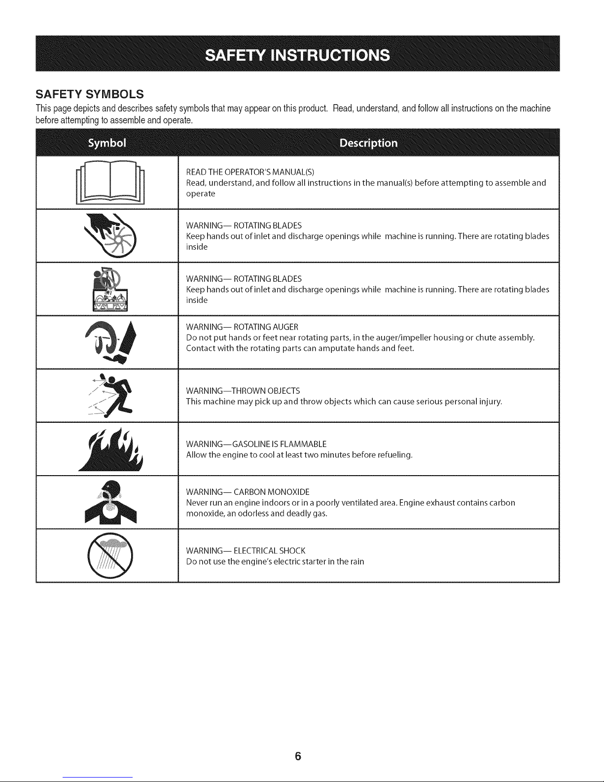
SAFETY SYMBOLS
Thispagedepictsanddescribessafetysymbolsthatmayappearonthisproduct. Read,understand,andfollowall instructionson themachine
beforeattemptingto assembleandoperate.
READ THE OPERATOR'S MANUAL(S)
i
. +
i
Read, understand, and follow all instructions in the manual(s) before attempting to assemble and
operate
WARNING-- ROTATING BLADES
Keep hands out of inlet and discharge openings while machine is running. There are rotating blades
inside
WARNING-- ROTATING BLADES
Keep hands out of inlet and discharge openings while machine is running. There are rotating blades
inside
WARNING-- ROTATING AUGER
Do not put hands or feet near rotating parts, in the auger/impeller housing or chute assembly.
Contact with the rotating parts can amputate hands and feet.
"JIp
WARNING--THROWN OBJECTS
This machine may pick up and throw objects which can cause serious personal injury.
WARNING--GASOLINE IS FLAMMABLE
Allow the engine to cool at least two minutes before refueling.
WARNING-- CARBON MONOXIDE
Never run an engine indoors or in a poorly ventilated area. Engine exhaust contains carbon
monoxide, an odorless and deadly gas+
WARNING-- ELECTRICAL SHOCK
Do not use the engine's electric starter in the rain
6
Page 7

Thispageleftintentionallyblank.
7
Page 8
NOTE:Referencesto rightorleft sideof the snowthrowerare
determinedfrombehindtheunitinthe operatingposition(standing
directlybehindthesnowthrower,facingthe handlepanel).
REMOVING FROM CARTON
1. Cutthe cornersof thecartonandlaythesidesflaton theground.
Removeanddiscardallpackinginserts.
2. Movethesnowthroweroutofthecarton.
3. Makecertainthecartonhas beencompletelyemptiedbefore
discardingit.
ASSEMBLY
1. Observethe lowerrearareaof the snowthrowerto besureboth
cablesarealignedwith rollerguidesbeforepivotingthehandle
upward.
a. Placetheshiftleverin theF6position.
b. Pullupandbackonupperhandleasshownin Figure1.As
youare raisingthehandleupward,makesurethatbothends
ofthecentercablearepositionedproperlyinthe brackets.
Alignupperhandlewiththe lowerhandle.
c. Tightenhandknobssecuringupperhandletolowerhandle.
Removeanddiscardanyrubberbands,ifpresent.Theyare
forpackagingpurposesonly.
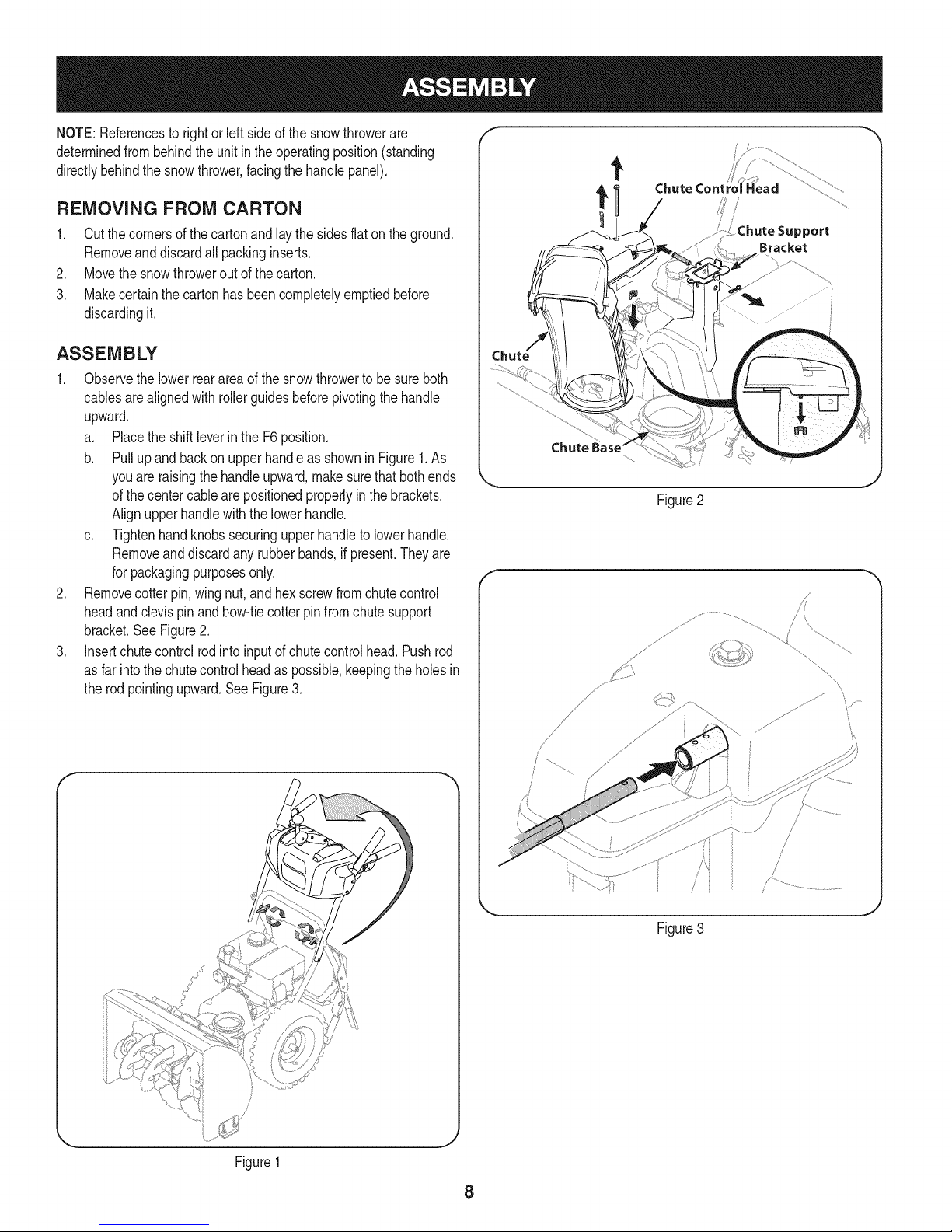
2. Removecotterpin,wingnut,and hexscrewfromchutecontrol
headandclevispinandbow-tiecotterpinfromchutesupport
bracket.See Figure2.
3. Insertchutecontrolrodintoinputof chutecontrolhead.Pushrod
asfarintothe chutecontrolheadaspossible,keepingtheholesin
therodpointingupward.SeeFigure3.
Chute Control Head
_ort
Bracket
Figure2
f
/
Figure1
/
/
/
J
Figure3
J
8
Page 9
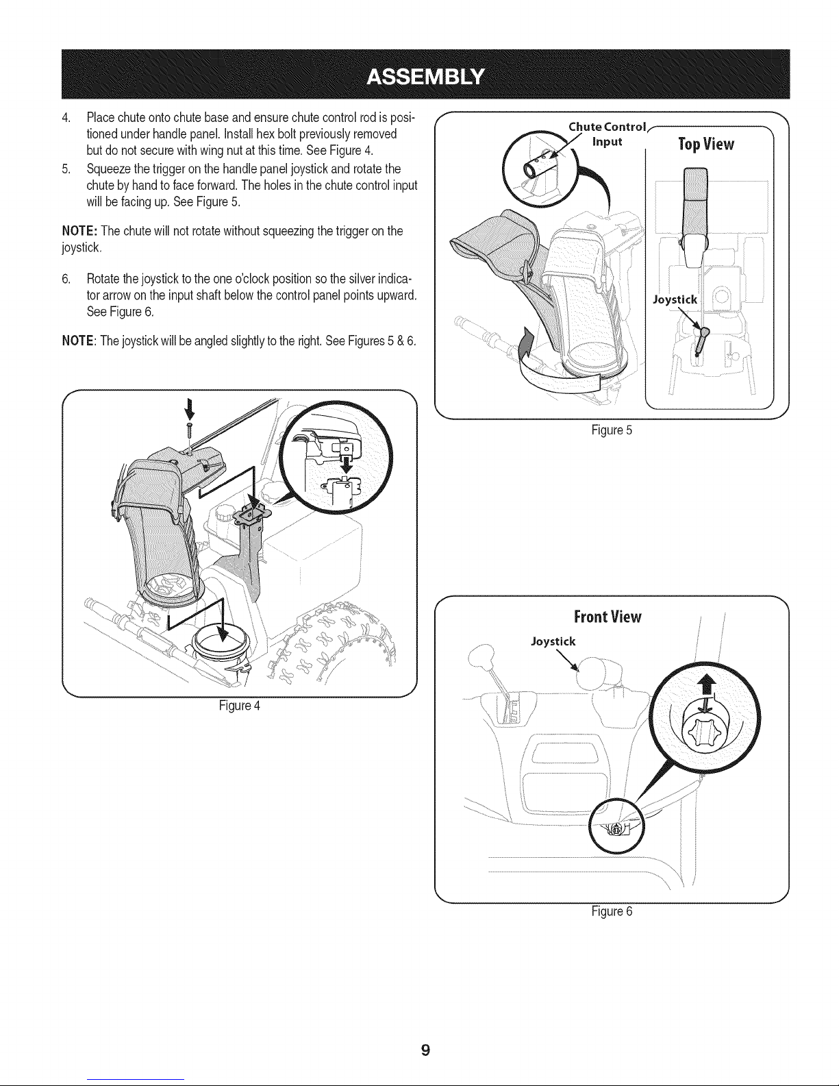
4. Placechuteontochutebaseandensurechutecontrolrodis posi-
tionedunderhandlepanel.Installhexboltpreviouslyremoved
butdonotsecurewithwingnutatthistime.SeeFigure4.
5. Squeezethetriggeron thehandlepaneljoystickand rotatethe
chutebyhandtofaceforward.Theholes inthechutecontrolinput
willbefacingup.SeeFigure5.
NOTE:The chutewill not rotatewithoutsqueezingthetriggeronthe
joystick.
6. Rotatethejoysticktotheoneo'clockpositionsothesilverindica-
torarrowontheinputshaftbelowthecontrolpanelpointsupward.
SeeFigure6.
NOTE:Thejoystickwillbeangledslightlytotheright.SeeFigures5 & 6.
f
Chute Controlf
Figure5
Figure4
f
FroatView
Joystick
J
Figure6
9
Page 10
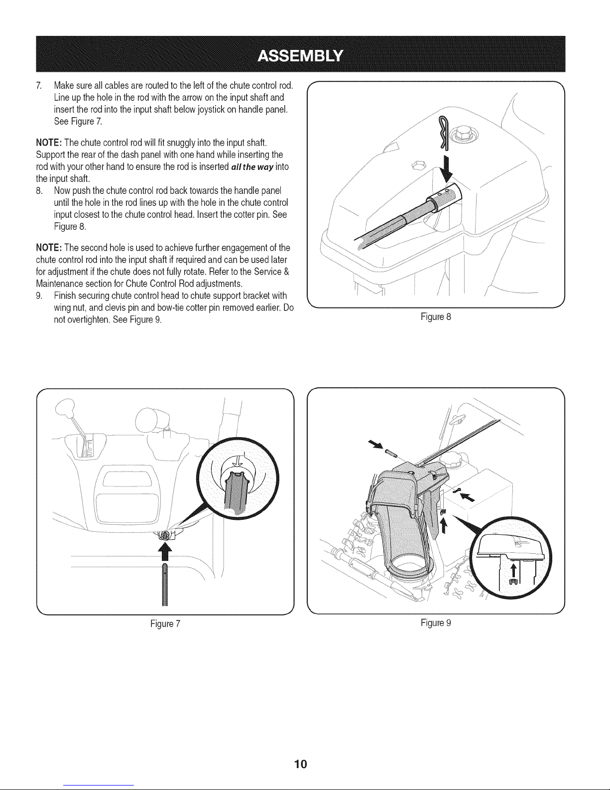
Makesureall cablesare routedtotheleftofthechutecontrolrod.
Lineupthe holein the rodwiththearrowonthe inputshaftand
inserttherodintotheinputshaftbelowjoystickonhandlepanel.
SeeFigure7.
NOTE:The chutecontrolrodwillfit snugglyintotheinputshaft.
Supportthe rearof the dashpanelwithone handwhileinsertingthe
rodwithyourotherhandtoensurethe rodisinsertedallthe way into
theinputshaft.
8. Nowpushthechutecontrolrodbacktowardsthehandlepanel
untilthe holein the rodlinesupwiththeholein thechutecontrol
inputclosestto the chutecontrolhead.Insertthecotterpin.See
Figure8.
NOTE:The secondholeisusedto achievefurtherengagementof the
chutecontrolrodintotheinputshaftifrequiredandcanbe usedlater
foradjustmentif thechutedoesnotfullyrotate.Refertothe Service&
MaintenancesectionforChuteControlRodadjustments.
9. Finishsecuringchutecontrolheadto chutesupportbracketwith
wingnut,andclevispinand bow-tiecotterpinremovedearlier.Do
notovertighten.SeeFigure9.
Figure8
y..................
\
Figure7
Figure9
10
Page 11
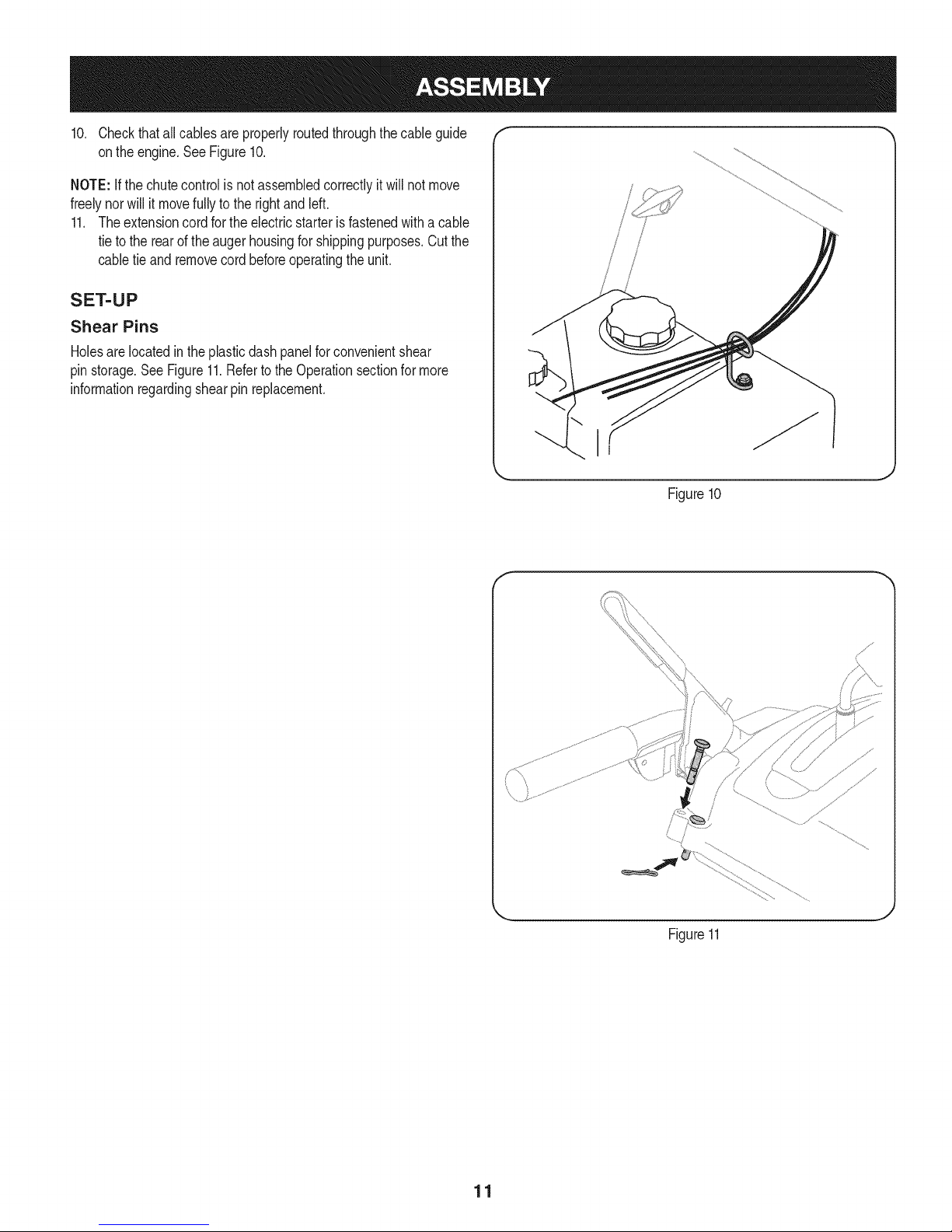
10. Checkthatall cablesareproperlyroutedthroughthecableguide
ontheengine.SeeFigure10.
NOTE:Ifthechutecontrolis notassembledcorrectlyitwillnotmove
freelynorwillit movefullyto the rightandleft.
11. Theextensioncordfortheelectricstarteris fastenedwitha cable
tietotherearoftheaugerhousingforshippingpurposes.Cutthe
cabletie and removecordbeforeoperatingtheunit.
SET-UP
Shear Pins
Holesare locatedintheplasticdashpanelforconvenientshear
pinstorage.SeeFigure11.Referto the Operationsectionformore
informationregardingshearpin replacement.
/
i
i I
iili,
!
Figure10
J
Figure11
11
Page 12
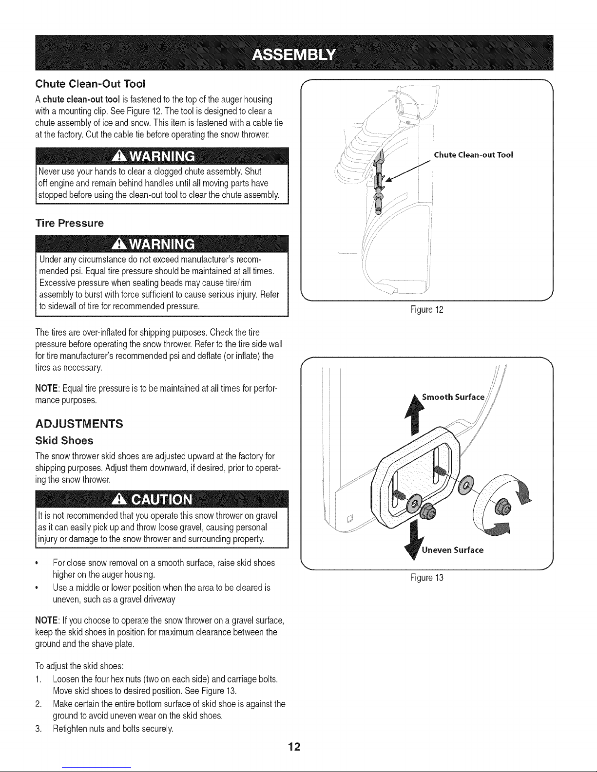
Chute Clean=Out Tool
Achute clean-out tool isfastenedtothe top of the augerhousing
witha mountingclip.SeeFigure12.Thetoolisdesignedtocleara
chuteassemblyoficeandsnow.Thisitemisfastenedwitha cabletie
atthefactory.Cutthecabletiebeforeoperatingthe snowthrower.
loff m=ovingpartshave
stoppedbeforeusingtheclean-outtooltoclearthechuteassembly.
Tire Pressure
Underanycircumstancedo notexceedmanufacturer'srecom-
mendedpsi.Equaltirepressureshouldbemaintainedatall times.
Excessivepressurewhenseatingbeadsmaycausetire/rim
assemblytoburstwithforcesufficienttocauseseriousinjury.Refer
tosidewallof tirefor recommendedpressure.
Thetiresareover-inflatedforshippingpurposes.Checkthetire
pressurebeforeoperatingthe snowthrower.Referto the tire sidewall
fortiremanufacturer'srecommendedpsianddeflate(or inflate)the
tiresasnecessary.
................
Chute Clean-out Tool
_J
Figure12
//'
NOTE:Equaltire pressureistobe maintainedat alltimesfor perfor-
mancepurposes.
ADJUSTMENTS
Skid Shoes
Thesnowthrowerskidshoesareadjustedupwardatthefactoryfor
shippingpurposes.Adjustthemdownward,ifdesired,priorto operat-
ingthesnowthrower.
It is not recommendedthatyouoperatethissnowthrowerongravel
asitcaneasilypickup andthrowloosegravel,causingpersonal
njuryordamageto the snowthrowerandsurroundng property.
• Forclosesnowremovalona smoothsurface,raiseskidshoes
higherontheaugerhousing.
• Usea middleor lowerpositionwhentheareatobe clearedis
uneven,suchas a graveldriveway
NOTE:If youchoosetooperatethesnowthrowerona gravelsurface,
keepthe skidshoesin positionfor maximumclearancebetweenthe
groundandtheshaveplate.
Toadjustthe skidshoes:
1. Loosenthefour hexnuts(twooneach side)andcarriagebolts.
Moveskidshoestodesiredposition.SeeFigure13.
2. Makecertaintheentirebottomsurfaceof skidshoeisagainstthe
groundtoavoidunevenwearontheskidshoes.
3. Retightennutsand boltssecurely.
Smooth Surface
Surface
Figure13
12
Page 13
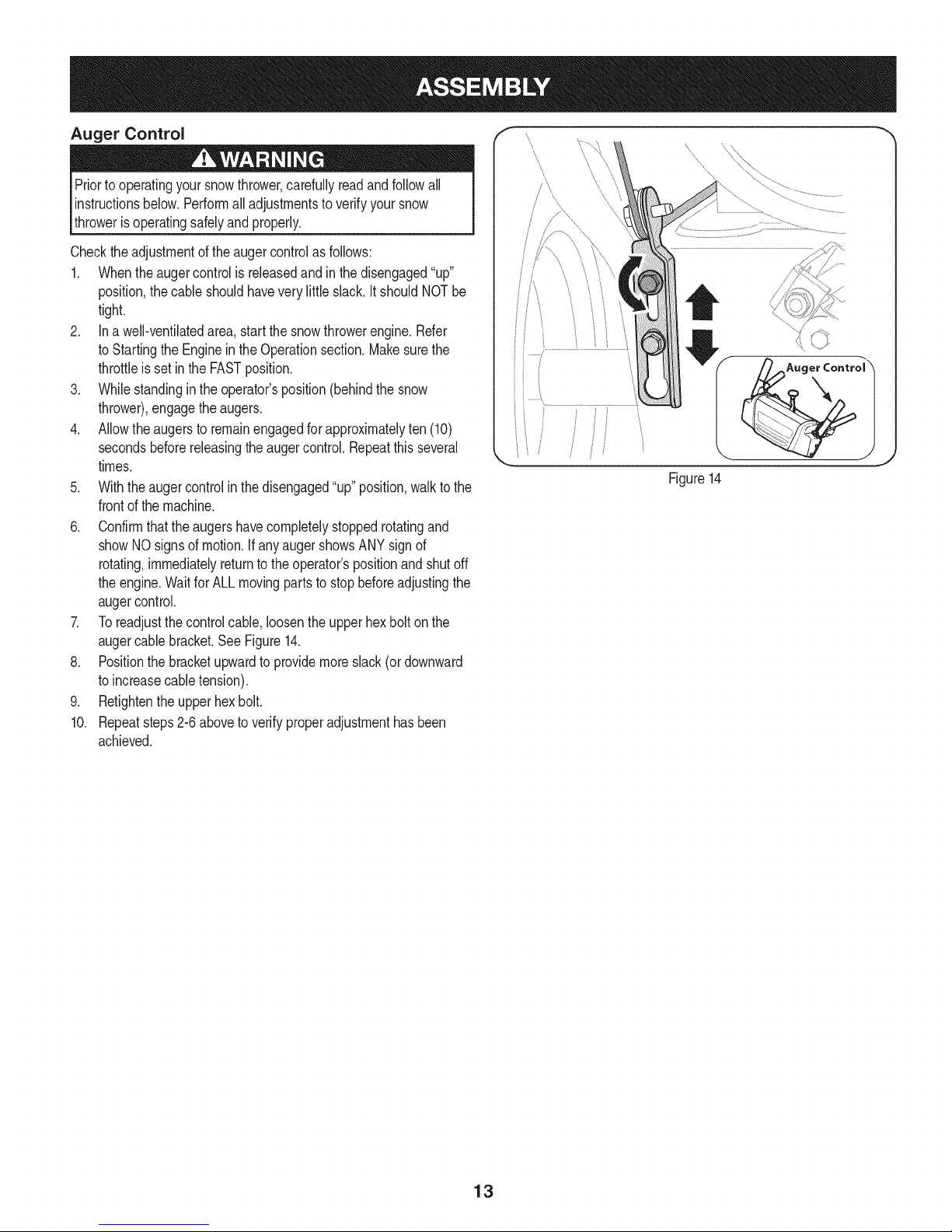
Auger Control
Priortooperatingyoursnowthrower,carefullyreadandfollowall
instructionsbelow.Performalladjustmentsto verifyyoursnow
throwerisoperatingsafelyandproperly.
Checktheadjustmentof the augercontrolas follows:
1. Whentheaugercontrolis releasedandin thedisengaged"up"
position,thecableshouldhavevery littleslack.ItshouldNOTbe
tight.
2. Ina well-ventilatedarea,startthesnowthrowerengine.Refer
toStartingtheEngineintheOperationsection.Makesurethe
throttleis setin the FASTposition.
3. Whilestandingintheoperator'sposition(behindthe snow
thrower),engagethe augers.
4. Allowtheaugersto remainengagedforapproximatelyten(10)
secondsbeforereleasingthe augercontrol.Repeatthisseveral
times.
5. Withtheaugercontrolinthedisengaged"up" position,walkto the
frontofthemachine.
6. Confirmthattheaugershavecompletelystoppedrotatingand
showNOsignsof motion.IfanyaugershowsANYsignof
rotating,immediatelyreturntotheoperator'spositionandshutoff
theengine.WaitforALLmovingpartstostopbeforeadjustingthe
augercontrol.
7. Toreadjustthecontrolcable,loosentheupperhexbolt onthe
augercablebracket.SeeFigure14.
8. Positionthe bracketupwardtoprovidemoreslack(or downward
toincreasecabletension).
9. Retightentheupperhexbolt.
10. Repeatsteps2-6aboveto verifyproperadjustmenthasbeen
achieved.
/_Auger Control \
Figure14
13
Page 14
f
Auger
Chute Assembly
Clean Out
Tool
\
Drive Control
Gas Cap
\
\
Shift Lever
Four-Way Chute ControP (Joystick)
J
J
Auger Control
\
\
\
Muffler Recoil Starter
'\ Handle
Primer FUEL LEVEL
\
\
Hous_
Augers
_ Skid Shoe
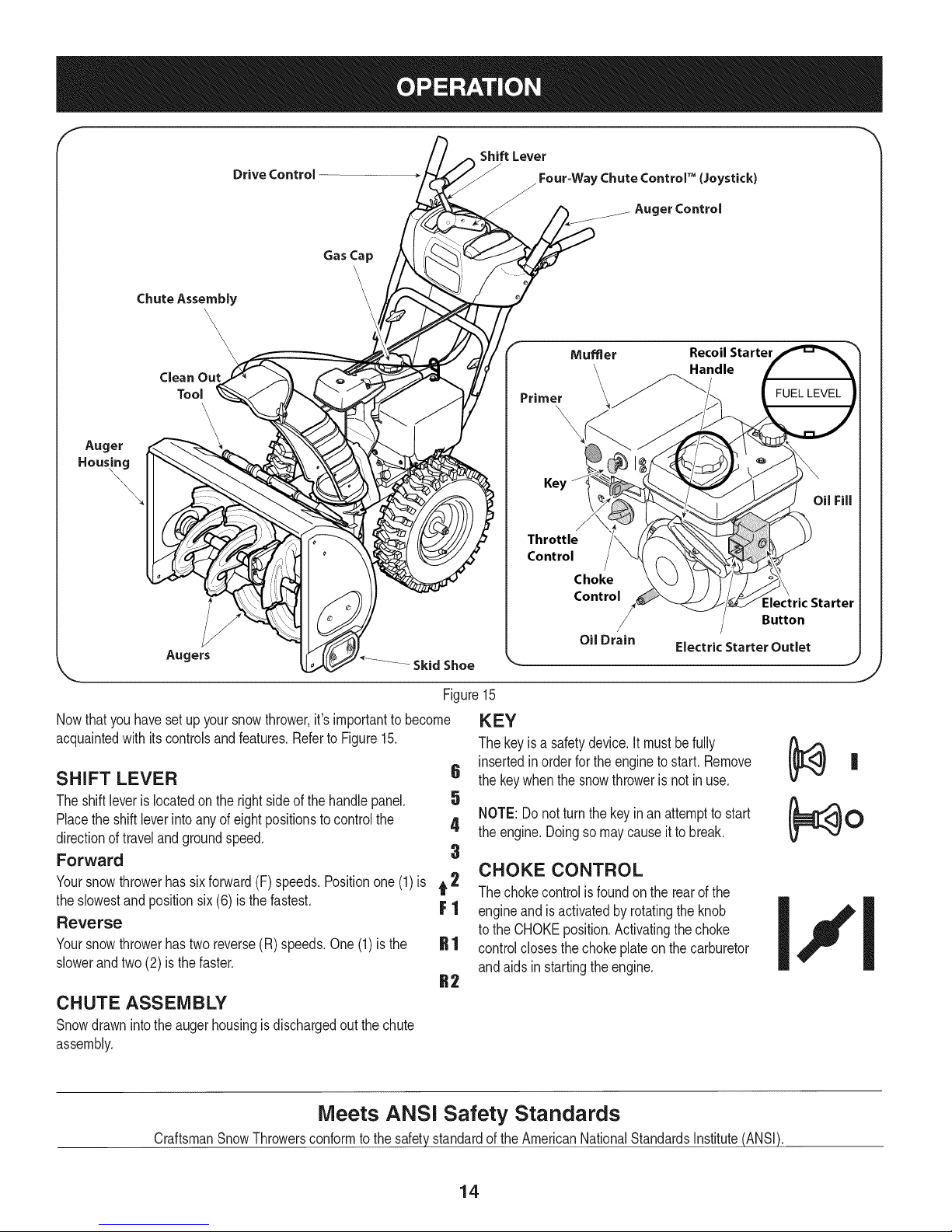
Figure15
Nowthat youhavesetup yoursnowthrower,it'simportanttobecome
acquaintedwith itscontrolsandfeatures.Referto Figure15.
SHIFT LEVER 6
Theshiftleverislocatedonthe rightsideofthehandlepanel. 5
Placethe shiftleverintoanyof eightpositionstocontrolthe 4
directionoftravelandgroundspeed.
Forward 3
Yoursnowthrowerhassixforward(F)speeds.Positionone(1)is t 2
theslowestand positionsix (6) isthefastest. F 1
Reverse
Yoursnowthrowerhastwo reverse(R)speeds.One(1)is the
slowerandtwo(2) isthefaster.
Key
Throttle
Control
Choke
Control
Oil Drain
Electric Starter Outlet
KEY
Thekeyisa safetydevice.It mustbefully
insertedinorderfortheenginetostart. Remove
thekeywhenthesnowthrowerisnotin use.
NOTE:Donot turnthekeyinan attemptto start
theengine.Doingsomaycauseit tobreak.
CHOKE CONTROL
Thechokecontrolisfoundon therearofthe
engineand is activatedbyrotatingtheknob
totheCHOKEposition.Activatingthe choke
controlclosesthe chokeplateon thecarburetor
andaidsin startingthe engine.
=lectric Starter
Button
CHUTE ASSEMBLY
Snowdrawnintotheaugerhousingisdischargedoutthechute
assembly.
Meets ANSi Safety Standards
CraftsmanSnowThrowersconformto the safetystandardoftheAmericanNationalStandardsInstitute(ANSI).
14
Page 15
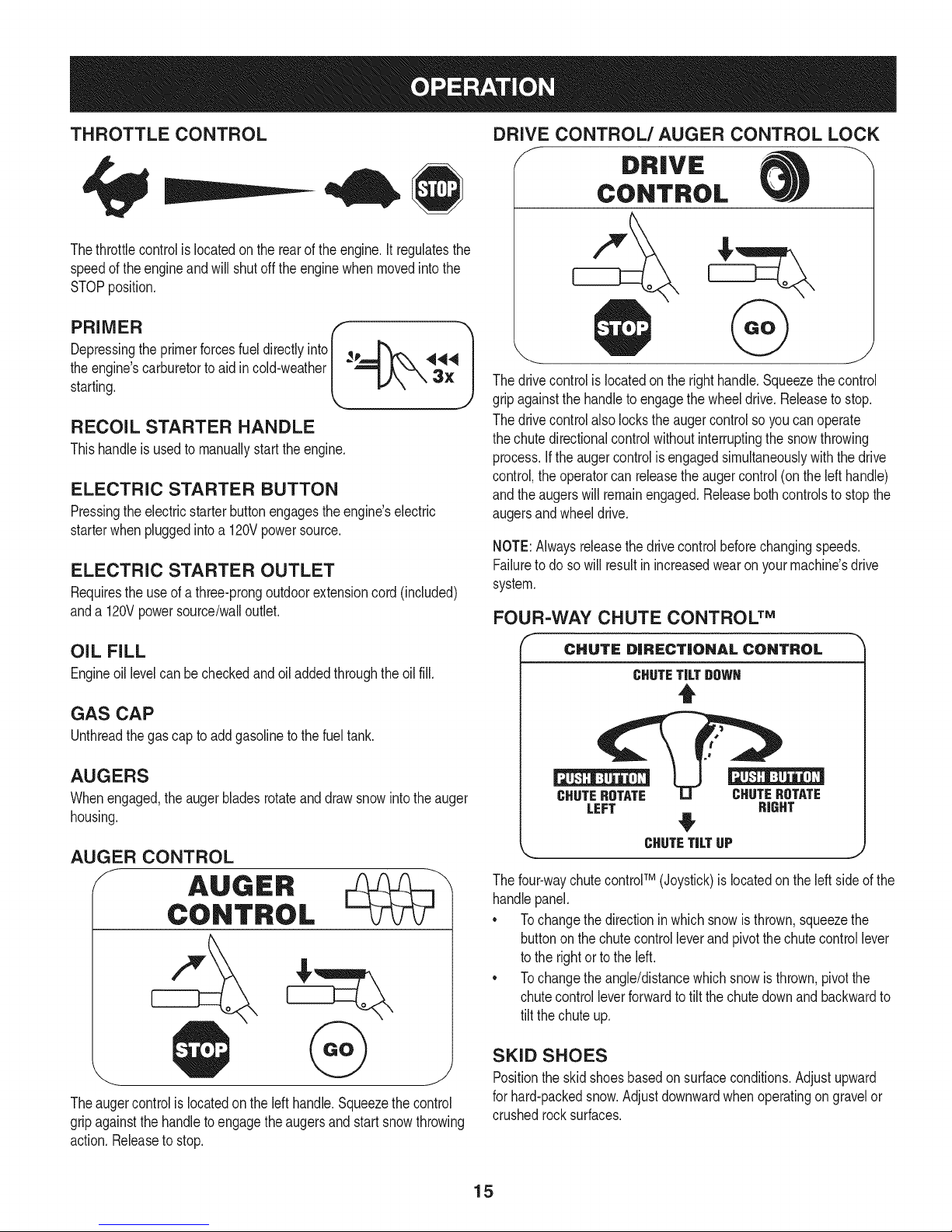
THROTTLE CONTROL
Thethrottlecontrolis locatedon therearoftheengine.It regulatesthe
speedof theengineandwillshutoff the enginewhenmovedintothe
STOPposition.
DRIVE CONTROL/AUGER CONTROL LOCK
f DRIVE
CONTROL
Depressingthe primerforcesfuel directlyinto _p
theengine'scarburetortoaid incold-weather
starting.
RECOIL STARTER HANDLE
Thishandleisusedto manuallystarttheengine.
ELECTRIC STARTER BUTTON
Pressingtheelectricstarterbuttonengagestheengine'selectric
starterwhenpluggedintoa 120Vpowersource.
ELECTRIC STARTER OUTLET
Requirestheuseof athree-prongoutdoorextensioncord(included)
anda 120Vpowersource/walloutlet.
OIL FILL
Engineoil levelcanbecheckedandoiladdedthroughtheoil fill.
GAS CAP
Unthreadthegascaptoaddgasolinetothe fuel tank.
AUGERS
Whenengaged,theaugerbladesrotateanddrawsnowintotheauger
housing.
AUGER CONTROL
f AUGER
CONTROL
@
Thedrivecontrolis locatedontherighthandle.Squeezethecontrol
gripagainstthehandletoengagethewheeldrive.Releaseto stop.
Thedrivecontrolalso lockstheaugercontrolsoyoucanoperate
thechutedirectionalcontrolwithoutinterruptingthesnowthrowing
process.If theaugercontrolis engagedsimultaneouslywiththedrive
control,the operatorcanreleasetheaugercontrol(onthelefthandle)
andtheaugerswillremainengaged.Releasebothcontrolstostopthe
augersandwheeldrive.
NOTE:Alwaysreleasethedrivecontrolbeforechangingspeeds.
Failureto dosowillresultinincreasedwearon yourmachine'sdrive
system.
FOUR-WAY CHUTE CONTROL TM
f
CHUTE DiRECTiONAL CONTROL
CHUTETiLTDOWH
t
CHUTEROTATE CHUTEROTATE
LEFT RIGHT
CHUTETiLTUP
Thefour-waychutecontroFM(Joystick)islocatedon theleft sideofthe
handlepanel.
* Tochangethe directioninwhichsnowisthrown,squeezethe
buttononthechutecontrolleverand pivotthe chutecontrollever
tothe rightortotheleft.
* Tochangethe angle/distancewhichsnowisthrown,pivotthe
chutecontrolleverforwardtotiltthechutedownandbackwardto
tilt the chuteup.
Theaugercontrolislocatedontheleft handle.Squeezethecontrol
gripagainstthehandletoengagetheaugersandstartsnowthrowing
action.Releasetostop.
SKID SHOES
Positiontheskidshoesbasedonsurfaceconditions.Adjustupward
forhard-packedsnow.Adjustdownwardwhenoperatingon gravelor
crushedrocksurfaces.
15
Page 16
CLEAN-OUT TOOL
Neveruseyourhandsto cleara cloggedchuteassembly.Shut
off engineandremainbehindhandlesuntilall movingpartshave
stoppedbeforeusingtheclean-outtoolto clear thechuteassembly.
Thechuteclean-outtoolisconvenientlyfastenedtothe rearofthe
augerhousingwitha mountingclip. Shouldsnowandice become
lodgedin thechuteassemblyduringoperation,proceedasfollowsto
safelycleanthechuteassemblyandchuteopening:
1. ReleaseboththeAugerControlandtheDriveControl.
2. Stoptheenginebyremovingtheignitionkey.
3. Removetheclean-outtoolfromtheclipwhichsecuresit to the
rearoftheaugerhousing.
4. Usethe shovel-shapedendof theclean-outtooltodislodgeand
scoopanysnowand icewhichhasformedin andnearthechute
assembly.
5. Refastenthe clean-outtooltothemountingclip ontherearof
theaugerhousing,reinserttheignitionkeyandstartthe snow
thrower'sengine.
6. Whilestandingintheoperator'sposition(behindthesnow
thrower),engagethe augercontrolfora fewsecondstoclear any
remainingsnowandice fromthechuteassembly.
BEFORE STARTING ENGINE
Read,understand,andfollowall instructionsandwarningsonthe
machineand inthismanualbeforeoperating.
Oil
Theunit wasshippedwith oil inthe engine.Checkoillevelbefore
eachoperationtoensureadequateoil intheengine.Forfurther
instructions,refertothe stepson page18.
NOTE:Besureto checktheengineon alevelsurfacewiththeengine
stopped.
1. Removetheoil fillercap/dipstickandwipethe dipstickclean.
2. insertthecap/dipstickintothe oilfillerneck,andtightenthecap
untilseated.
3. Removetheoil fillercap/dipstick,ifthelevelislow,slowlyadd
oil (5%30, witha minimumclassificationof SF/SG)untiloil level
registersbetweenhigh(H) andlow(L).
NOTE:Do notoverfill.Overfillingwithoilmayresultinenginesmoking,
hardstartingorsparkplugfouling.
4. Replaceandtightencap/dipstickfirmlybeforestartingengine.
Gasoline
Useautomotivegasoline(unleadedor low leadedto minimizecombus-
tionchamberdeposits)witha minimumof 87octane.Gasolinewith
upto 10%ethanolor 15%MTBE(MethylTertiaryButylEther)canbe
used.Neveruseanoil/gasolinemixtureordirtygasoline.Avoidgetting
dirt,dust,or waterinthefuel tank. DO NOTuse E85gasoline.
• Refuelina well-ventilatedareawiththeenginestopped.Donot
smokeorallowflamesor sparksin theareawherethe engineis
refueledor wheregasolineisstored.
• Donot overfillthe fueltank.After refueling,makesurethe tank
capisclosedproperlyandsecurely.
• Becarefulnotto spillfuel whenrefueling.Spilledfuelorfuel vapor
mayignite,ifany fuelis spilled,makesuretheareaisdrybefore
startingthe engine.
• Avoidrepeatedorprolongedcontactwithskinor breathingof
)or.
Useextremecarewhenhandlinggasoline.Gasolineisextremely
flammableandthevaporsare explosive.Neverfuelthemachine
indoorsorwhiletheengineishotor running.Extinguishcigarettes,
cigars,pipesandothersourcesof ignition.
1. Cleanaroundfuel fill beforeremovingcaptofuel.
2. A fuellevelindicatorislocatedinthe fueltank.SeeFigure15
inset.Becarefulnottooverfill.Filltank untilfuel reachesthefuel
levelindicatortoallowspaceforfuelexpansion.
STARTING THE ENGINE
Alwayskeephandsandfeetclearof movingparts.Donotusea
pressurizedstartingfluid.Vaporsareflammable.
NOTE:Allowtheenginetowarmupfora fewminutesafter starting.
Theenginewillnotdevelopfullpoweruntilitreachesoperating
temperatures.
1. Makecertainboththeaugercontrolanddrivecontrolarein the
disengaged(released)position.
2. insertignitionkeyinto slot.Makesure itsnapsintoplace.Donot
attempttoturnthekey.
NOTE:Theenginecannotstartwithoutthekeyisfully insertedintothe
ignitionswitch.
Electric Starter
Theoptionalelectricstarterisequippedwitha groundedthree-wire
powercordand plug,andis designedtooperateon120voltAC
householdcurrent.Itmustbe usedwitha properlygroundedthree-
prongreceptacleat all timesto avoidthepossibilityof electricshock.
Followall instructionscarefullypriortooperatingtheelectricstarter.
DONOTuseelectricstarterinthe rain.
Determinethatyourhome'swiringisa three-wiregroundedsystem.
Aska licensedelectricianif you arenotcertain.
Ifyou havea groundedthree-prongreceptacle,proceedasfollows.
Ifyou donothavethe properhousewiring,DONOTusetheelectric
starterunderanyconditions.
1. Plugtheextensioncordintothe outletlocatedon theengine's
surface.Plugtheotherendof extensioncord intoa three-prong
120-volt,grounded,ACoutletina well-ventilatedarea.
16
Page 17
2. MovethrottlecontroltoFAST(rabbit)_ position.
3. MovechoketotheCHOKEI,"1pos t /co denginestart).If
engineiswarm,placechokein RUNposition.
4. Pushprimerthree(3)times,makingsuretocoverventholewhen
pushing.Ifengineiswarm,pushprimeronlyonce.Alwayscover
ventholewhenpushing.Coolweathermayrequireprimingtobe
repeated.
5. Pushstarterbuttonto start engine.Oncethe enginestarts,im-
mediatelyreleasestarterbutton.Electricstarteris equippedwith
thermaloverloadprotection;systemwilltemporarilyshut-downto
allowstartertocoolifelectricstarterbecomesoverloaded.
6. Astheenginewarms,slowlyrotatethe chokecontroltoRUN
position.Iftheenginefalters,restartengineandrunwithchoke
athalf-chokepositionfor a shortperiodoftime,andthenslowly
rotatethechokeintoRUNposition.
7. Afterengineis running,disconnectpowercordfromelectric
starter.Whendisconnecting,alwaysunplugtheendatthewall
outletbeforeunpluggingtheoppositeendfromthe engine.
Recoil Starter
Donotpullthestarterhandlewhiletheenginerunning.
1. Movethrottlecontrolto FAST(rabbit)_ position.
2. MovechoketotheCHOKEJ..#Jposition(coldenginestart).If
engineiswarm,placechokein RUNposition.
3. Pushprimerthree(3)times,makingsuretocoverventholewhen
pushing.Ifengineiswarm,pushprimeronlyonce.Alwayscover
ventholewhenpushing.Coolweathermayrequireprimingtobe
repeated.
4. Pullgentlyonthe starterhandleuntilitbeginstoresist,then
pullquicklyandforcefullytoovercomethecompression.Engine
shouldstart.Donot releasethehandleandallowittosnapback.
ReturnropeSLOWLYtooriginalposition.If required,repeatthis
step.
5. Astheenginewarms,slowlyrotatethe chokecontroltoRUN
position.Iftheenginefalters,restartengineandrunwithchoke
athalf-chokepositionfor a shortperiodoftime,andthenslowly
rotatethechokeintoRUNposition.
TO ENGAGE DRIVE
1. Withthethrottlecontrolinthe Fast(rabbit)'_ position,move
shiftleverintooneof thesix forward(F) positionsortwo reverse
(R)positions.Selecta speedappropriateforthesnowconditions
anda paceyou'recomfortablewith.
NOTE:Whenselectinga DriveSpeed,usethe slowerspeedsuntil
youarecomfortableandfamiliarwiththeoperationofthesnow
thrower.
2. Squeezethedrivecontrolagainstthehandleandthesnow
throwerwillmove.Releaseitanddrivemotionwillstop.
NOTE:NEVERrepositionthe shiftlever(changespeedsordirection
oftravel)withoutfirst releasingthedrivecontrolandbringingthesnow
throwertoa completestop.Doingsowill resultin prematurewearto
thesnowthrower'sdrivesystem.
TO ENGAGE AUGERS
1. Toengagethe augersandstartthrowingsnow,squeezethe
augercontrolagainstthelefthandle.Releasetostoptheaugers.
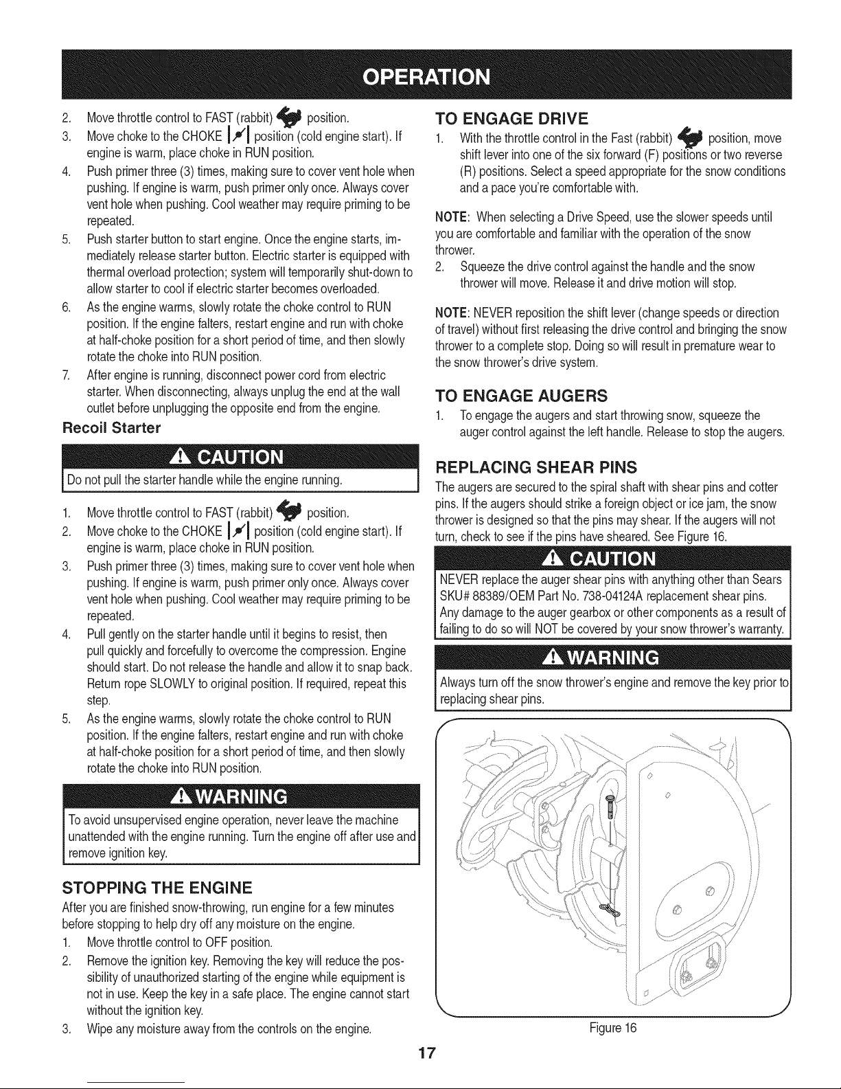
REPLACING SHEAR PINS
Theaugersaresecuredtothespiralshaftwith shearpinsandcotter
pins.If the augersshouldstrikeaforeignobjectoricejam,the snow
throwerisdesignedsothatthe pins mayshear.If theaugerswillnot
turn,checktoseeifthepinshavesheared.SeeFigure16.
NEVERreplacethe augershearpinswithanythingotherthanSears
SKU#88389/0EMPartNo.738-04124Areplacementshearpins.
Anydamagetotheaugergearboxorothercomponentsas a resultof
[fa ngto dosow NOTbe coveredby yoursnowthrowerswarranty.
Alwaysturnoff the snowthrower'sengineandremovethekeypriorto
replacingshearpins.
o
Toavoid unsupervisedengineoperation,neverleavethemachine
unattendedwiththeenginerunning.Turntheengineoffafteruseand
removeignitionkey.
STOPPING THE ENGINE
Afteryouarefinishedsnow-throwing,runenginefora fewminutes
beforestoppingtohelpdry offanymoistureonthe engine.
1. Movethrottlecontrolto OFFposition.
2. Removetheignitionkey.Removingthekeywill reducethepos-
sibilityof unauthorizedstartingof theenginewhileequipmentis
notinuse.Keepthe keyin a safeplace.Theenginecannotstart
withouttheignitionkey.
3. Wipeanymoistureawayfromthecontrolsontheengine.
iJ
Figure16
17
Page 18
MAINTENANCE SCHEDULE
Beforeperforminganytypeofmaintenance/service,disengageall
controlsandstoptheengine.Waituntilallmovingpartshavecometo
acompletestop.Disconnectsparkplugwireandgrounditagainstthe
enginetopreventunintendedstarting.Alwayswearsafetyglassesduring
operationor whileperforminganyadjustmentsorrepairs.
EachUseandevery5
hours
1st5 hours
Annuallyor25hours
Annuallyor50hours
Annuallyor100hours
BeforeStorage
1. Engineoillevel
2. Looseormissinghardware
3. Unitandengine.
1. Engineoil
1. Sparkplug
2. Controllinkagesand pivots
3. Wheels
4. GearshaftandAugershaft
5. 4-WayChuteControlTM
1. Engineoil
1. Sparkplug
1. Fuelsystem
1. Check
2. Tightenor replace
3. Clean
1. Change
1. Check
2. Lubewithlightoil
3. Lubewithmultipurposeautogrease
4. Lubewithlightoil
5. Checkforcableslackness
1. Change
1. Change
1. Runengineuntilit stopsfromlack
Followthemaintenanceschedulegivenbelow.Thischartdescribes
serviceguidelinesonly.UsetheServiceLogcolumnto keeptrackof
completedmaintenancetasks.To locate the nearestSearsService
Centeror toscheduleservice,simplycontactSearsat
1-800-4-MY-HOME®.
offuel
ENGINE MAINTENANCE
Beforelubricating,repairing,or inspecting,disengageall controls
Iandstopengine.Waituntilall movingpartshavecometo a complete
_stop.
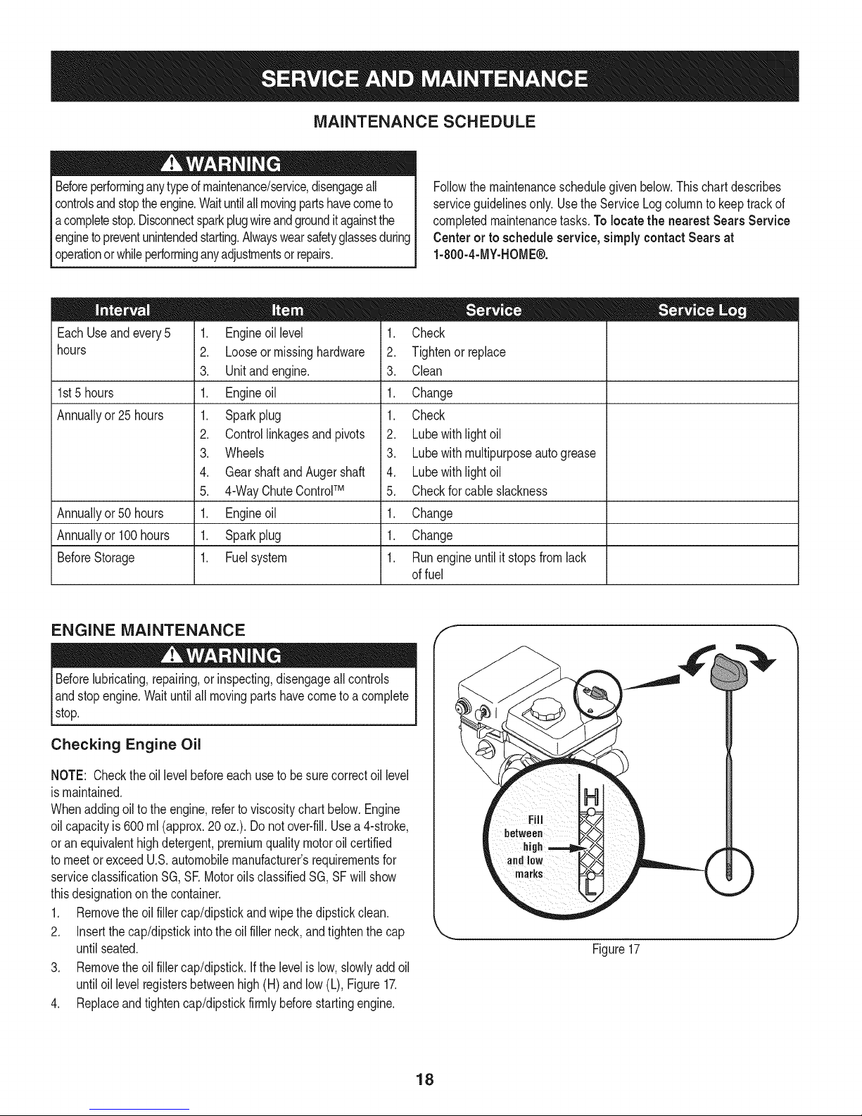
Checking Engine Oil
NOTE: Checktheoil levelbeforeeachuseto besurecorrectoil level
ismaintained.
Whenaddingoiltotheengine,referto viscositychart below.Engine
oilcapacityis 600ml (approx.20oz.).Donot over-fill.Usea 4-stroke,
oran equivalenthighdetergent,premiumqualitymotoroilcertified
tomeetorexceedU.S.automobilemanufacturer'srequirementsfor
serviceclassificationSG, SR MotoroilsclassifiedSG,SFwillshow
thisdesignationonthecontainer.
1. Removetheoil fillercap/dipstickandwipethe dipstickclean.
2. Insertthecap/dipstickintothe oilfillerneck,andtightenthecap
untilseated.
3. Removetheoil fillercap/dipstick.Ifthe levelislow,slowlyaddoil
untiloil levelregistersbetweenhigh(H) and low(L), Figure17.
4. Replaceandtightencap/dipstickfirmlybeforestartingengine.
f
Figure17
18
Page 19
Changing Engine Oil
NOTE:Changetheengineoilafterthe first 5hoursof operationand
oncea seasonorevery50hoursthereafter.
1. Drainfuelfromtankbyrunningengineuntilthe fuel tankisempty.
Besurefuelfillcapissecure.
2. Placesuitableoil collectioncontainerunderoildrainplug.
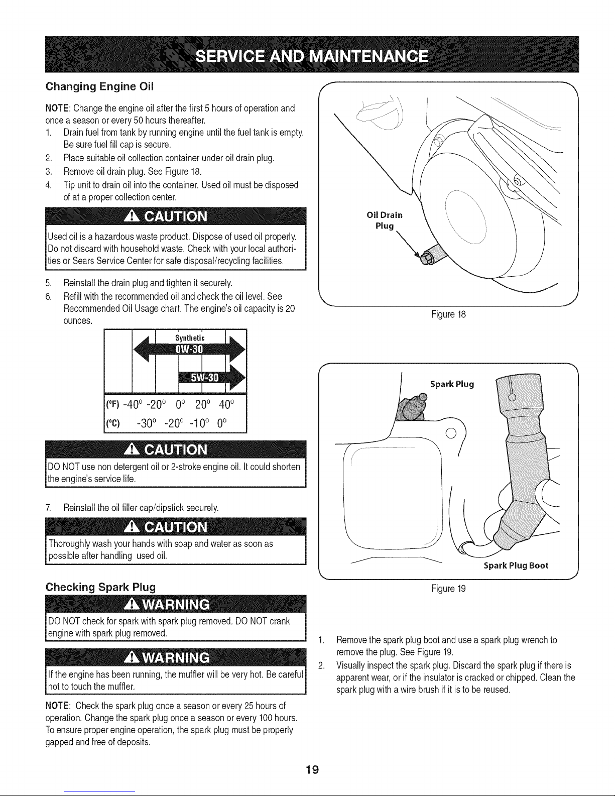
3. Removeoildrainplug.SeeFigure18.
4. Tipunittodrainoil intothecontainer.Usedoil mustbe disposed
ofata propercollectioncenter.
Usedoil isa hazardouswasteproduct.Disposeof usedoil properly.
Donotdiscardwith householdwaste.Checkwithyourlocalauthori-
tiesor SearsServiceCenterforsafedisposal/recyclingfacilities.
.
Reinstallthedrainplugandtightenit securely.
6.
Refillwiththerecommendedoilandchecktheoil level.See
RecommendedOil Usagechart.Theengine'soilcapacityis20
ounces.
u i
Synthetic
Oil Drain
Plug
_=, ,J
Figure18
(0F)-40o-20 o 0o 200 400
("c) -30° -20° -10° 0°
DONOTuse nondetergentoilor 2-strokeengineoil.It couldshorten
theengine'sservicelife.
7. Reinstalltheoilfillercap/dipsticksecurely.
Thoroughlywashyourhandswithsoapandwaterassoonas
possibleafterhandling usedoil.
Checking Spark Plug
DONOTcheckfor sparkwithsparkplugremoved.DONOTcrank
enginewithsparkplugremoved.
Iftheenginehasbeenrunning,themufflerwillbevery hot.Becareful
notto touchthemuffler.
NOTE: Checkthe sparkplugoncea seasonorevery25hoursof
operation.Changethesparkplugoncea seasonor every100hours.
Toensureproperengineoperation,thesparkplugmustbe properly
gappedandfreeofdeposits.
Spark Plug
©
J
Figure19
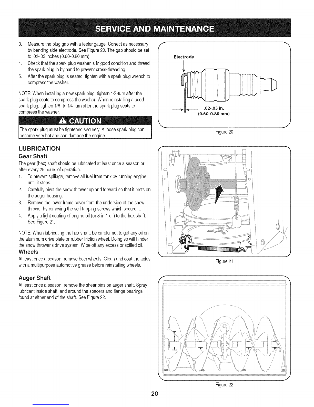
1. Removethesparkplugbootand usea sparkplugwrenchto
removetheplug.SeeFigure19.
2. Visuallyinspectthesparkplug.Discardthe sparkplugifthereis
apparentwear,oriftheinsulatoriscrackedorchipped.Cleanthe
sparkplugwithawirebrushif it is to be reused.
19
Page 20
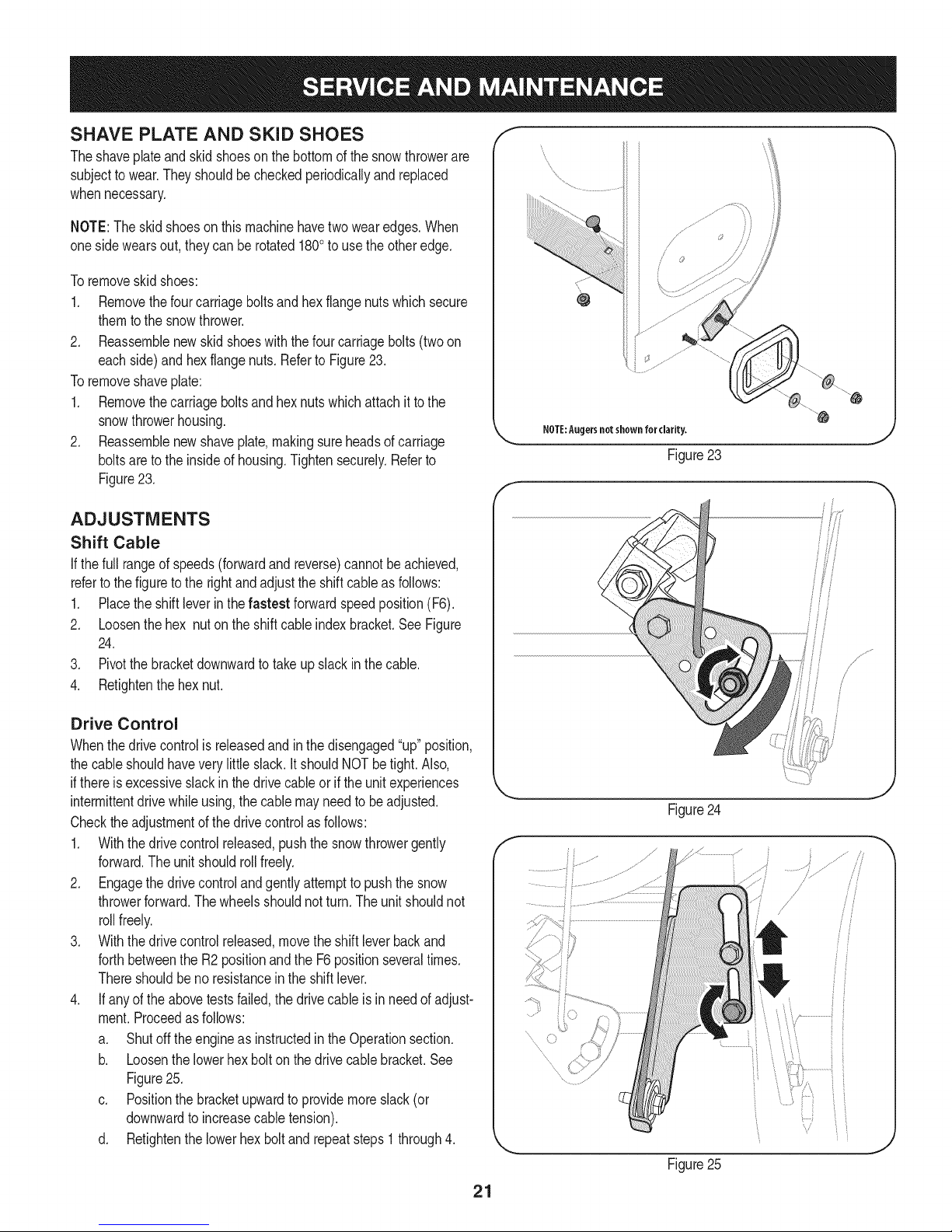
3. Measurethe pluggapwitha feelergauge.Correctas necessary
bybendingsideelectrode.SeeFigure20.Thegap shouldbe set
to.02-.03inches(0.60-0.80ram).
4. Checkthatthesparkplugwasheris ingoodconditionandthread
thesparkplugin byhandto preventcross-threading.
5. Afterthe sparkplugis seated,tightenwitha sparkplugwrenchto
compressthewasher.
NOTE:Wheninstallinga newsparkplug,tighten1/2-turnafterthe
sparkplugseatstocompressthewasher.Whenreinstallinga used
sparkplug,tighten1/8-to 1/4-turnafterthesparkplugseatsto
compressthewasher.
hotandcan ine.
LUBRICATION
Gear Shaft
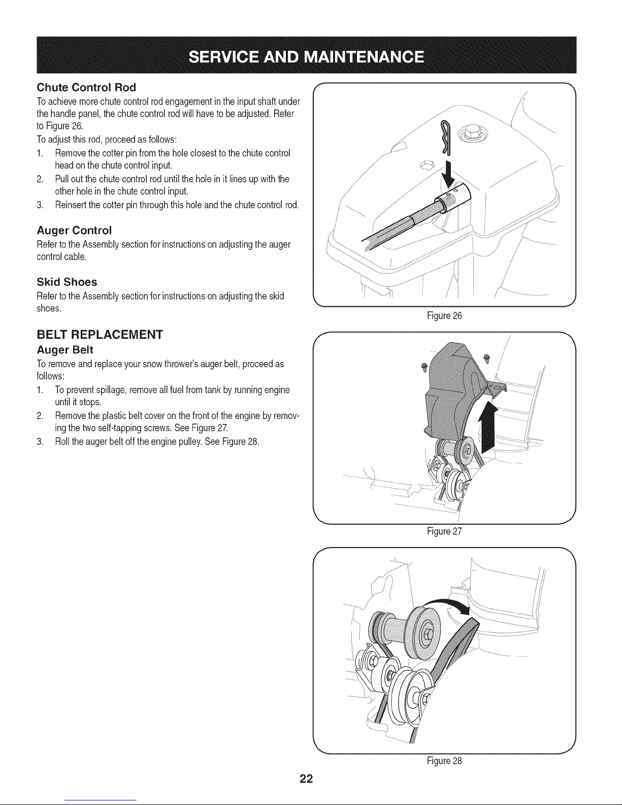
Thegear(hex)shaft shouldbe lubricatedatleastoncea seasonor
afterevery25 hoursof operation.
1. Topreventspillage,removeallfuel fromtank byrunningengine
untilitstops.
2. Carefullypivotthesnowthrowerupandforwardsothat itrestson
theaugerhousing.
3. Removethe lowerframecoverfromthe undersideofthesnow
throwerbyremovingtheself-tappingscrewswhichsecureit.
4. Applya lightcoatingofengineoil (or3-in-1oil) to the hexshaft.
SeeFigure21.
f
J
Figure20
NOTE:Whenlubricatingthehexshaft,be carefulnottogetanyoilon
thealuminumdriveplateor rubberfrictionwheel.Doingsowillhinder
thesnowthrower'sdrivesystem.Wipeoff anyexcessor spilledoil.
Wheels
Atleastoncea season,removebothwheels.Cleanandcoattheaxles
witha multipurposeautomotivegreasebeforereinstallingwheels.
Auger Shaft
Atleastoncea season,removetheshearpinson augershaft.Spray
lubricantinsideshaft,andaroundthespacersandflangebearings
foundat eitherendof the shaft.SeeFigure22.
Figure21
f
\
J
Figure22
2O
Page 21
SHAVE PLATE AND SKiD SHOES
Theshaveplateand skidshoesonthebottomofthesnowthrowerare
subjectto wear.Theyshouldbecheckedperiodicallyandreplaced
whennecessary.
NOTE:Theskidshoesonthismachinehavetwowearedges.When
onesidewearsout, theycan be rotated1800to usethe otheredge.
Toremoveskidshoes:
1. Removethefourcarriageboltsandhexflangenutswhichsecure
themtothe snowthrower.
2. Reassemblenewskidshoeswiththefour carriagebolts(twoon
eachside)and hexflangenuts.Referto Figure23.
Toremoveshaveplate:
1. Removethecarriageboltsand hexnutswhichattachit tothe
snowthrowerhousing.
2. Reassemblenewshaveplate,makingsureheadsof carriage
boltsareto the insideofhousing.Tightensecurely.Referto
Figure23.
ADJUSTMENTS
Shift Cable
If thefull rangeofspeeds(forwardandreverse)cannotbeachieved,
referto the figuretotherightandadjusttheshiftcableasfollows:
1. Placethe shiftleverin thefastest forwardspeedposition(F6).
2. Loosenthehex nutontheshiftcableindexbracket.SeeFigure
24.
3. Pivotthebracketdownwardtotakeupslack inthecable.
4. Retightenthehexnut.
NOTE:Augersnotshown for clarity.
Figure23
fj
Drive Control
Whenthedrivecontrolisreleasedandinthedisengaged"up"position,
thecableshouldhaveverylittle slack.It shouldNOTbetight.Also,
ifthereisexcessiveslackinthedrivecableor if the unitexperiences
intermittentdrivewhileusing,the cable mayneedtobeadjusted.
Checktheadjustmentof the drivecontrolasfollows:
1. Withthedrivecontrolreleased,pushthesnowthrowergently
forward.Theunitshouldrollfreely.
2. Engagethe drivecontrolandgentlyattempttopushthe snow
throwerforward.Thewheelsshouldnotturn.The unitshouldnot
rollfreely.
3. Withthedrivecontrolreleased,movetheshiftleverbackand
forthbetweenthe R2positionandthe F6 positionseveraltimes.
Thereshouldbeno resistanceintheshiftlever.
4. If anyoftheabovetestsfailed,thedrivecable isinneedof adjust-
ment.Proceedasfollows:
a. Shutoff theengineas instructedintheOperationsection.
b. Loosenthelowerhexboltonthe drivecablebracket.See
Figure25.
c. Positionthebracketupwardtoprovidemoreslack(or
downwardto increasecabletension).
d. Retightenthelowerhex boltand repeatsteps1 through4.
21
Figure24
f
/
/
........
Figure25
Page 22
Chute Control Rod
Toachievemorechutecontrolrodengagementinthe inputshaftunder
thehandlepanel,thechutecontrolrodwillhaveto beadjusted.Refer
toFigure26.
Toadjustthis rod,proceedasfollows:
1. Removethecotterpinfromtheholeclosestto the chutecontrol
headon the chutecontrolinput.
2. Pullout thechutecontrolroduntiltheholein it linesupwiththe
otherholein thechutecontrolinput.
3. Reinsertthecotterpinthroughthisholeandthechutecontrolrod.
Auger Control
RefertotheAssemblysectionforinstructionsonadjustingtheauger
controlcable.
Skid Shoes
RefertotheAssemblysectionforinstructionsonadjustingtheskid
shoes.
BELT REPLACEMENT
Auger Belt
Toremoveandreplaceyoursnowthrower'saugerbelt,proceedas
follows:
1. Topreventspillage,removeallfuel fromtank byrunningengine
untilitstops.
2. Removethe plasticbeltcoveronthe frontoftheenginebyremov-
ingthetwoself-tappingscrews.SeeFigure27.
3. Rolltheaugerbeltoff theenginepulley.SeeFigure28.
/
/
/
/
/
/
Figure26
f
J
Figure27
f
/
Figure28
22
Page 23
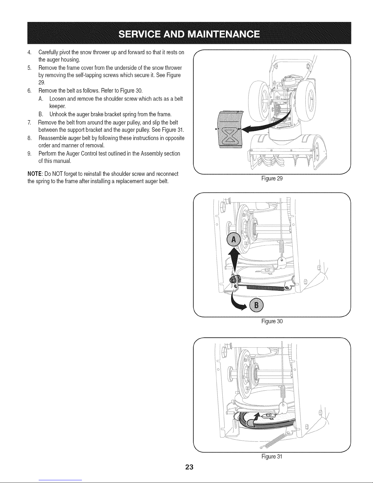
4. Carefullypivotthesnowthrowerupandforwardsothatitrestson
theaugerhousing.
5. Removetheframecoverfromtheundersideofthesnowthrower
byremovingtheself-tappingscrewswhichsecureit.SeeFigure
29.
6. Removethebeltasfollows.RefertoFigure30.
A. Loosenandremovetheshoulderscrewwhichactsasabelt
keeper.
B. Unhooktheaugerbrakebracketspringfromtheframe.
7. Removethebeltfromaroundtheaugerpulley,andslipthebelt
betweenthesupportbracketandtheaugerpulley.SeeFigure31.
8. Reassembleaugerbeltbyfollowingtheseinstructionsinopposite
orderandmannerofremoval.
9. PerformtheAugerControltestoutlinedintheAssemblysection
ofthismanual.
/
NOTE:Do NOTforgetto reinstalltheshoulderscrewandreconnect
thespringtotheframeafterinstallinga replacementaugerbelt.
Figure29
f
Figure30
f
Figure31
23
Page 24
Drive Belt
Toremoveandreplaceyoursnowthrower'sdrivebelt,proceedas
follows:
1. Topreventspillage,removeallfuel fromtank byrunningengine
untilitstops.
2. Removethe plasticbeltcoveronthe frontoftheenginebyremov-
ingthetwoself-tappingscrews.SeeFigure27on previouspage.
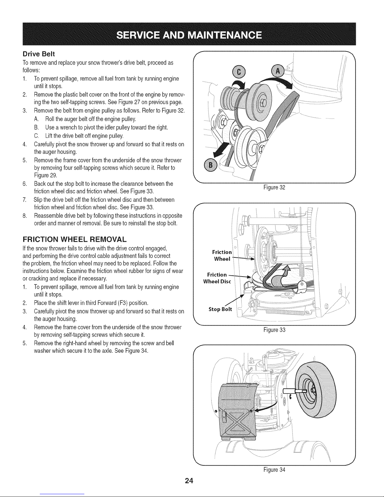
3. Removethe beltfromenginepulleyas follows.Referto Figure32.
A. Rollthe augerbeltoff theenginepulley.
B. Usea wrenchto pivottheidlerpulleytowardthe right.
C. Liftthedrivebeltoffenginepulley.
4. Carefullypivotthesnowthrowerup andforwardsothat itrestson
theaugerhousing.
5. Removetheframecoverfromtheundersideof thesnowthrower
byremovingfourself-tappingscrewswhichsecureit.Referto
Figure29.
6. Backoutthestopboltto increasetheclearancebetweenthe
frictionwheeldiscandfrictionwheel.SeeFigure33.
7. Slipthedrivebeltoffthefrictionwheeldiscandthenbetween
frictionwheelandfrictionwheeldisc.SeeFigure33.
8. Reassembledrivebeltbyfollowingtheseinstructionsin opposite
orderandmannerof removal.Besureto reinstallthestopbolt.
J
Figure32
FRICTION WHEEL REMOVAL
Ifthe snowthrowerfailstodrivewiththedrivecontrolengaged,
andperformingthe drivecontrolcableadjustmentfailstocorrect
theproblem,thefrictionwheelmayneedtobe replaced.Followthe
instructionsbelow.Examinethefrictionwheelrubberfor signsof wear
orcrackingandreplaceif necessary.
1. Topreventspillage,removeallfuel fromtank byrunningengine
untilitstops.
2. Placetheshiftleverin thirdForward(F3)position.
3. Carefullypivotthesnowthrowerupandforwardsothat itrestson
theaugerhousing.
4. Removetheframecoverfromtheundersideof the snowthrower
byremovingself-tappingscrewswhichsecureit.
5. Removethe right-handwheelbyremovingthe screwandbell
washerwhichsecureitto theaxle.SeeFigure34.
Friction
Wheel
Friction
WheelDisci i
Figure33
f
J
Figure34
24
Page 25

.
Carefullyremovethe hexnutandwasherwhichsecuresthehex
shaftto the snowthrowerframeand lightlytaptheshaft'send _;!
todislodgetheballbearingfromtherightsideoftheframe.See
Figure35. .]_j
NOTE:Becarefulnottodamagethethreadson theshaft.
7. Carefullypositionthehexshaftdownwardandto the left before
carefullyslidingthefrictionwheelassemblyoff theshaft.See
Figure36.
NOTE:Ifyou'rereplacingthefrictionwheelassemblyasa whole,
discardthewornpartand slidethenewpartontothe hexshaft.
8. Followthestepsaboveinreverseorderto reassemblecompo-
nents.
9. Performthe DriveControlTestoutlinedearlierintheServiceand
Maintenancesection.
If you'redisassemblingthefrictionwheeland replacingonlytherubber
ring,proceedasfollows:
1. Removethefourscrewswhichsecurethe frictionwheel'sside
platestogether.SeeFigure37.
2. Removetherubberringfrombetweentheplates.
3. Reassemblethesideplateswitha newrubberring.
Figure36
NOTE: Whenreassemblingthefrictionwheelassembly,makesure
thattherubberringis centeredandseatedproperlybetweenthe side
plates.Tighteneachscrewonlyone rotationbeforeturningthewheel
clockwiseandproceedingwiththe nextscrew.Repeatthisprocess
severaltimestoensurethe platesaresecuredwithequalforce
(between6 ft-lbsand 9ft-lbs).
4. Slidethefrictionwheelassemblybackontothehexshaftand
reassemblecomponentsbyfollowingtheseinstructionsin
oppositeorderand mannerofremoval.
5. Performthe DriveControlTestoutlinedearlierintheServiceand
Maintenancesection.
f
J
Figure37
Figure35
Page 26

Ifthesnowthrowerwillnotbeusedfor30daysorlonger,orifitistheendofthesnowseasonwhenthelastpossibilityofsnowisgone,the
equipmentneedstobestoredproperly.Followstorageinstructionsbelowtoensuretopperformancefromthesnowthrowerformanymoreyears.
PREPARING ENGINE
Enginesstoredover30daysneedtobedrainedoffueltoprevent
deteriorationandgumfromforminginfuelsystemoronessential
carburetorparts.If thegasolineinyourenginedeterioratesduring
storage,youmayneedto havethecarburetor,andotherfuelsystem
components,servicedor replaced.
1. Removeall fuel fromtank byrunningengineuntilitstops.Donot
attempttopourfuelfromtheengine.
2. Changetheengineoil.
3. Removesparkplugandpourapproximately1oz.(30 rnl)ofclean
engineoil intothecylinder.Pullthe recoilstarterseveraltimesto
distributetheoil,and reinstallthesparkplug.
4. Cleandebrisfromaroundengine,andunder,around,andbehind
muffler.Applya lightfilmof oilon anyareasthatare susceptible
torust.
• Storeina clean,dry andwellventilatedareaawayfromanyap-
pliancethatoperateswithaflameor pilotlight,suchasa furnace,
waterheater,or clothesdryer.Avoidanyareawitha spark
producingelectricmotor,orwherepowertoolsareoperated.
Neverstoresnowthrowerwithfuelintank indoorsor inpoorlyventi-
latedareas,wherefuelfumesmayreachanopenflame,sparkor pilol
lightas ona furnace,waterheater,clothesdryerorgasappliance.
PREPARING SNOW THROWER
Whenstoringthe snowthrowerin anunventilatedormetalstor-
age shed,careshouldbetakentorustprooftheequipment.Using
a light oilor silicone,coattheequipment,especiallyanychains,
springs,bearingsandcables.
• Removealldirt fromexteriorofengineandequipment.
• Followlubricationrecommendations.
• Storeequipmentin a clean,dry area.
• Inflatethetirestothe maximumPSi. Referto tiresidewall.
• If possible,avoidstorageareaswithhighhumidity.
• Keepthe enginelevelin storage.Tiltingcan causefuel oroil
leakage.
26
Page 27

Enginefailsto start
Enginerunningerratically/
inconsistentRPM(huntingor
surging)
Excessivevibration
Lossofpower
Unitfailstopropelitself
Unitfailstodischargesnow
1. ChokecontrolnotinCHOKEposition.
2. Sparkplugwiredisconnected.
3. Faultysparkplug.
4. Fueltankemptyor stalefuel.
5. Enginenotprimed.
6. Keynotinserted.
7. Extensioncordnotconnected(when
usingelectricstartbutton,on modelsso
equipped).
1. EnginerunningonCHOKE.
2. Stalefuel.
3. Waterordirt infuelsystem.
4. Over-governedengine.
1. Loosepartsor damagedauger.
1. Sparkplugwireloose.
2. Gascapventholeplugged.
1. Drivecableinneedofadjustment.
2. Drivebeltlooseor damaged.
3. Wornfrictionwheel.
1. Chuteassemblyclogged.
2. Foreignobjectlodgedin auger.
3. Augercablein needof adjustment.
4. Augerbeltlooseordamaged.
5. Shearpin(s)sheared.
1. Movechokecontrolto CHOKEposition.
2. Connectwireto sparkplug.
3. Clean,adjustgap,or replace.
4. Filltankwith clean,freshgasoline.
5. Primeengineasinstructedinthe OperationSection.
6. Insertkeyfully intotheswitch.
7. Connectoneendoftheextensioncordtotheelectric
starteroutletandtheotherendtoa three-prong
120-volt,grounded,ACoutlet.
1. Movechokecontrolto RUNposition.
2. Filltankwith clean,freshgasoline.
3. Drainfueltankby runningengineuntilitstops.Refill
withfreshfuel.
4. ContactyourSearsParts& RepairCenter.
1. Stopengineimmediatelyand disconnectsparkplug
wire.Tightenall boltsand nuts.Ifvibrationcontinues,
haveunit servicedbya SearsParts& RepairCenter.
1. Connectandtightensparkplugwire.
2. Removeiceand snowfromgascap. Becertainvent
holeisclear.
1. Adjustdrivecontrolcable.RefertoServiceand
Maintenancesection.
2. Replacedrive belt.Referto Serviceand Mainte-
nancesection.
3. Havefrictionwheelreplacedata SearsParts&
RepairCenter.
1. Stopengineimmediatelyand disconnectsparkplug
wire.Cleanchuteassemblyandinsideofauger
housingwithclean-outtoolor astick.
2. Stopengineimmediatelyand disconnectsparkplug
wire.Removeobjectfromaugerwith clean-outtool
ora stick.
3. Adjustaugercontrolcable.Referto Assembly
section.
4. Replaceaugerbelt.RefertoServiceand Mainte-
nancesection.
5. Replacewith newshearpin(s).
Chutefailstoeasilyrotate180 1. Disassemblechutecontroland reassembleas
1. Chuteassembledincorrectly.
degrees directedintheAssemblysection.
NEED HORE HELP?
Yot,Fttfind. th_ answer a!ld mo_e on ma_age_y_ifeocom _ for free]
Find this and att your other product manua[s ontine.
Get answers from our team of home experts.
Get a personalized maintenance p[an for your home.
Find information and tools to he[p with home projects.
managemylife
b_e'_g_t_/_eyeu by Sea_s
27
Page 28

Craftsman Snow Thrower Model 247.889704
i )
t
_39_
- _' ',_1;f
28
Page 29

Craftsman Snow Thrower IViodel 247.889704
D = 0
931-2643 Clean-OutTool
2. 712-04065 FlangeLockNut
3. 756-04224 FiatidlerPulley
4. 710-0347 HexBolt,3/8-16x 1.75
5. 790-00080B AugerIdlerBracket
6. 736-0174 WaveWasher
7. 938-0281 ShoulderScrew
8. 738-0143 ShoulderScrew
9. 790-00075 BearingHousing
10. 926-04012 PushNut
11. 712-04063 FlangeLockNut,5/16-18
12. 941-0309 BallBearing
13. 732-04460 ExtensionSpring
14. 710-04484 Screw,5/16-18x0.750
15. J731-07525 J ChuteAdapter
16. 710-0703 CarriageScrew,1/4-20x 0.75
17. 731-2635 Clean-outToolMtg.Bracket
18. 684-04264-4044 AugerHousingAssembly,26-inch
19. 712-04064 FlangeLockNut,1/4-20
20. 918-04172B GearboxAssembly,26-inch
21. 731-06439 SlideShoe
22. 710-0451 CarriageBolt
23. 790-00121-4044 ShavePlate
24. 684-04057A-0637 ImpellerAssembly
25. 917-04126 WormShaft
26. 721-0327 OilSeal
27. 741-0662 FlangeBearing
28. 718-04071 ThrustCollar
D = B
741-0663 FlangeBearing
30. 710-0642 Screw,1/4-20x0.75
31. 790-00087A-0637 BearingHousing
32. 721-0325 Plug
33. 736-3084 FiatWasher
34. 715-04021 DowelPin
35. 684-04108-0637 SpiralAssembly-RH
36. 918-0123A ReducerHsg.-RH
37. 917-04861 WormGear,20T
38. 725-0157 CableTie
39. 738-04124A ShearPin
40. 914-0161 Key
41. 936-0351 FiatWasher
42. 921-0338 OilSeal
43. 741-0661A FlangeBearing
44. 918-0124A ReducerHsg.-LH
45. 711-04284 Axle,Auger,26"
46. 684-04107-0637 SpiralAssembly-LH
47. 714-04040 BowTieCotterPin
48. 731-04870 Spacer
49. 741-0493A FlangeBushing
50. 736-0188 FiatWasher
51. 941-0245 HexFlangeBearing
52. 736-0242 BellWasher
53. 929-0071A ExtensionCord
54. 946-04230A AugerClutchCable
55. 710-0276 Screw,Carriage,5/16-18x 1.00
56. 936-0159 Washer,Fiat,.349x .879x .063
29
Page 30

Craftsman Snow Thrower IViodel 247.889704
_'.'X
'J2_\
=
<
3O
......................................................,_!:...........................¢o_......................
Page 31

Craftsman Snow Thrower Model 247.889704
D = 0 0
684-04112C HandleEngagementAssemblyRH
2. _ 738-04367 _FlangeShoulderScrew
3. 731-04894D LockPlate
4. 684-04250 PivotRod
5. 935-0199A RubberBumper
6. 710-3069 Screw,1/4-20x.500
7. 731-04896B ClutchLockCam
8. 712-04081A ShoulderNut,1/4-20
9. 710-0627 HexScrew,5/16-24x .750
10. 731-06440A LowerChute
11. 720-0274 HandleGrip
12. 710-1233 Screw,#10-24x 0.375
13. 738-04348 ShoulderScrew,1/4-20
14. 710-04586 Screw,1/4-20x 1.625
15. 749-04190A-0637 UpperHandleRH
16. 710-0572 CarriageScrew,5/16-18x2.25
17. 720-04039 ShiftKnob
18. 753-06438 HandlePanel
19. 731-05324 Lens
20. 710-04071 CarriageBolt,5/16-18x 1.0
21. 631-04134B HandleClutchLockRHAssy
22. 914-0101 CotterPin
23. 712-04064 FlangeLockNut, 1/4-20
24. 732-0193 CompressionSpring
25. 790-00311A-0637 ShiftLever
26. 790-00248C-0637 PanelBracket
27. 738-04125 ShoulderScrew
28. 684-04311A-0637 ChuteSupportBracket
29. 946-04396A SpeedSelectorCable
30. 736-04446 FiatWasher,.25x.630x .0515
31. 710-0895 Hi-LoScrew,1/4-15x .75
32. 710-04370 HexScrew,1/4-20x 3.00
33. 731-04427A UpperChute
34. _918-04801A _4-WayChuteGearboxAssembly
35. 710-04187 Hi-LoScrew,1/4-15x0.5
36. 984-04338A 4-WayChuteControlTM Assembly
D = O
749-04191A-0637 UpperHandleLH
38. 710-04326 Screw,#8-16x0.50
39. 732-04219C ClutchLockSpring
40. 712-3087 WingNut, 1/4-20
41. 714-04040 BowTie CotterPin
42. 710-0262 CarriageBolt,5/16-18x 1.50
43. 631-04133A HandleClutchLockLHAssy
44. 684-04111B HandleEngagementAssemblyLH
45. 784-5594-0637 CableBracket
46. 920-0284 WingKnob
47. 712-04063 FlangeLockNut,5/16-18
48. 731-06451 ChuteTiltCableGuide
49. 711-04469A ClevisPin
50. 710-04484 Screw,5/16-18x 0.75
51. 749-04138A-0637 LowerHandle
52. 732-04238 TorsionSpring
53. 936-0267 FiatWasher
54. 914-0145 ClickPin
55. 936-0159 FiatWasher,.349x .879x .063
56. 747-05116 ChuteRod
57. 753-06151 HandleAssembly
58. 946-04528A 4-WayCable
946-04477 4-WayCablew/Clip(NotShown)
59. 731-04893A HandlePlunger
60. 710-04879 Screw,Mach.,#8-32x .750
61. 710-04353 Screw,#8x 1.00
62. 731-07031 HandleLever
63. 984-04324A ShiftAssembly
64. 753-06152 GearSetAssembly
65. 753-06153 HandleHousingAssembly
66. 710-1256 Screw,#8-18x 1.250
67. 684-04350 JointBlockAssembly
68. 715-04095 Pin
69. 715-0150 RollPin
-- 753-080181- ChuteKit(Incl.Ref.#10&33)
1-Availableforwarrantycoverageonly.Contacta Searsauthorized
serviceproviderfordetails.
31
Page 32

Craftsman Snow Thrower Model 247.889704
i,73/
<
32
Page 33

Craftsman Snow Thrower IViodel 247.889704
|= 0 =
656-04055 DiscAssembly,FrictionWheel
2. 684-04153 FrictionWheelAssembly,5.50D
3_ L684-04154B-0637_Supp°rtBracket,Friction Wheel
4. 684-04156A ShiftAssembly,Rod
5. 710-0627 HexScrew,5/16-24,.750,Gr5
6. 710-0788 Screw,1/4-20,1.000
7. 710-1652 Screw,1/4-20x .625
8. 712-04065 Nut,FlangeLock,3/8-16,Nylon
9. 712-0417A Nut,JamLock,5/8-18,Gr5,Nylon
10. 914-0126 Key,Hi Pro,3/16x3/4 Dia.
11. 916-0104 E-ring,.500Dia.
12. 716-0136 E-ring,Retaining,.875Dia.
13. 916-0231 E-ring,.750Dia.
14. 917-04209A HexShaft,.8125,7-Tooth
15. 917-04230A Gear,80-Tooth
16. 726-0221 SpeedNut, .500
17. 932-0264 ExtensionSpring
18. 736-0242 Washer,Bell, .340x.872x .060
19. .936-0287 Washer, Flat,.793x 1.24x .060
20. 736-04161 Washer,Flat,.75x 1.00x .060
21. 748-04112B Spacer,Shldr.,.3175IDx .500x .094
22. 735-04100 Plug,1/2 ID
23. 738-04184A Screw,Shoulder,.37x.105,1/4-20
24. 738-0924A Screw,1/4-28,.375
25. 941-0245 Bearing,HexFlangex .75ID
26. 941-0563 Bearing,Ball,17x40x 12
27. ,946-04229B _ClutchCable,Wheel,44.95"
28. 790-00289A-0637 Plate,Cover
29. 748-0190 Spacer,.508IDx .75ODx .68
30. 756-0625 Roller,Cable
31. 790-00096-0637 FrontGuideBracket,AugerCable
32. 790-00180A-4044 Frame
33. 790-00206A-0637 GuideBracket,AugerCable
34. 790-00207B GuideBracket,DriveCable
35. 790-00316-0637 Cover,Frame
36. 634-04148A-0911 WheelAssembly- RH
634-04147A-0911 WheelAssembly-LH
37. 731-04873 Spacer,1.25x .75x 3.0
38. 938-04168 Axle,.75x22"
D = O O
735-04099 Plug,3/8 ID
40. 710-0809 HexScrew,1/4-20,1.25,Gr5
41. 710-0191 HexScrew,3/8-24,1.25,Gr8
42. 710-0672 HexScrew,5/16-24,1.25,Gr5
43. 710-0654A Screw,Seres,3/8-16,1.00
44. 710-1245B HexScrew,5/16-24,.875,Gr8
45. 712-04064 Nut,FlangeLock,1/4-20,Nylon
46. 926-04012 Nut,Push-on,.25Dia.
47. 731-05353 Cover,Belt
48. 732-04308A Spring,Torsion,.850IDx .354
49. 736-0247 Washer,Flat,.406x 1.25x .157
50. 936-0119 Washer,Lock.3125
51. 736-0505 Washer,Flat,.34x 1.50x .150
52. 748-04053A Pulley,Adapter,.75Dia.
53. 936-0329 LockWasher
54. 750-04303 Spacer,.875IDx 1.185OD
55. 750-04477A Spacer,.340x .750x .360
56. 954-04050 Belt,AugerDrive
57. 954-04260 Belt,WheelDrive
58. 756-04109
59. 756-04113
60. 756-04252
61. 790-00208C
62. 684-04169
63. 750-04571
64. 935-04054
65. 710-0751
66. 732-04311A
67. 712-04063
68. 936-3015
69. 790-00217A-0637
70. 790-00218A-0637
71. 936-0264
72. 732-0705
73. 710-04022
Pulley,AugerDrive,8.1x .5
Pulley,Half,Vx 2.600OD
Pulley,Half,3/8-Vx 1.7160OD
IdlerBracket,WheelDrive
IdlerPulleyAssembly
Spacer,Shoulder,.26x .79x .538
Rubber,FrictionWheel,5.50D
HexScrew,1/4-20,.620,Gr5
Spring,Torsion,.750IDx .968
Nut,FlangeLock,5/16-18,Nylon
Washer,Flat,.469x .875x .105
PivotBracket,SpeedSelector
ShiftBracket,SpeedSelector
Washer,Fiat,.330x .630x .0635
CableControlWire
Screw,M8-1.25
74. 738-04439 ShoulderScrew
75. 710-0599 Screw,AB, 1/4-20x .500
76. 952Z270-SUA ReplacementEngine
33
Page 34

Craftsman Engine Model 270=SUA For Snow Model 247.889704
24
23
23
m
l
i
i19
!
i
120
i
i
i
i20
!
!
i
121
i
i
122
i
i
i
i23
!
i
i
124
i
951-11282
710-05001
951-14190
951-11289
712-04214
710-04915
951-10642B
2
21
m = 0 O
MufflerAssembly
MufflerStud
MufflerStudKit
MufflerGasket
Nut- M8
Bolt- M6X 12Zin
MufflerShroud
34
Page 35

Craftsman Engine Model 270=SUA For Snow Model 247.889704
41 _42
m
34
35
36
37
39
4O
41
42
43
951-10634
712-04213
951-11284
951-10757
951-10637
731-05632
951-10640
951-10635
710-04943
°0
Shroud-Engine
Nut
ChokeKnob
ThrottleKnob
Switch-Ignition
IgnitionKeySwitch
PushRod-Choke
Air FilterHeating
Bolt-M61X28MSpec
37
35
D = O O
35
Page 36

Craftsman Engine IViodel 270=SUA For Snow IViodel 247.889704
131-6asketKit-Complete
132-6asketKit-External
133- CompleteEngine
36
Page 37

Craftsman Engine IViodel 270=SUA For Snow IViodel 247.889704
m
5O
51
52
53
54
55
56
57
58
59
6O
61
62
63
64
65
66
67
68
69
951-12111
951-11632
951-12007
951-11633
710-04915
951-11113
951-11573
951-14053
736-04461
951-11902
714-04078
951-11575
951-11369
951-10307
951-11247A
951-11576
715-04092
715-04096
951-11371
951-12125
951-11246
D = O
PistonRingSet
PistonPinSnapRing
Piston
PistonPin
Bolt- M6X 12Zin
Shield- Air
ConnectingRodAssembly
GovernorShaft
Washer
GovernorSeal
CotterPin
CamshaftAssembly
Bearing
Key:Flywheel
CrankshaftKit
(Incl.62,63,64,74,79)
GovernorGear/Shaft
Pin-Dowel
DowlPin9X14
CrankcaseCoverGasket
CrankcaseCover
CrankcaseCoverKit
(Incl.62,68-74)
m
7O
71
73
74
75
76
77
78
79
130
131
132
133
710-04932
951-11283
951-11577
951-11368
951-11249
951-11060B
951-11350
736-04440
710-04906
951-11370
951-10641
951-11059A
951-10661B
952Z270-SUA
D = O O
Bolt
Oil FillPlugAssembly
O-Ring15.8X 2.5
OilSeal
CrankcaseKit
(Incl.59,62,74,75,79)
ShortblockAssembly
(Incl.4,21,27-29,44,46,
47,50-53,56-79)
Oil DrainPipe
Washer
Bolt- DrainPlug
OilSeal
Oil DrainAssembly
GasketKit-Complete
(Incl.4,21,27-29,32,44,
58,59,68,74,77,79)
GasketKit-External
(Incl.4,21,27-29,32,77)
CompleteEngine
37
Page 38

Craftsman Engine Model270-SUAForSnow Model 247.889704
18
15
13
44 _p 49 46 _46
129
_ U" -"45
17
131-GasketKit-Complete
132-GasketKit-External
133-CompleteEngine
38
Page 39

Craftsman Engine IViodel 270=SUA For Snow IViodel 247.889704
m
1
2
3a
3b
4
5
6
7
8
9
10
11
12
13
14
15
16
17
18
44
45
46
47
48
49
129
131
132
133
710-04968
951-11054A
731-07059
726-04101
951-11565
951-12000
951-11892
751-11124
751-11123
951-11893
710-04902
951-12002
951-12003
951-12004
951-11894
710-04933
951-11895
951-10722B
951-10292
951-11572
951-10648
951-11899
715-04108
951-10647A
951-10647A
951-12626
951-11059A
951-10661B
952Z270-SUA
D = O O
FlangeBoltM6
ValveCover
Hose-Breather
Clamp-BreatherHose
ValveCoverGasket
IntakeValveSpringRetainer
RockerArmAssembly
Nut- PivotLockin
Nut- ValveAdjust
RockerArm
Bolt- Pivot
ExhaustValveAdjuster
ExhaustValveSpringRetainer
ValveSpring
IntakeValveSeal
Bolt- M8X 55Zin
PushRodGuide
CylinderHeadAssembly
(Incl.4-14,16,17,21,27-29,
44,48,49)
Plug:Spark
Gasket-CylinderHead
Kit-PushRod
Tappet
Pin-Dow110X 16
ValveKit
ValveKit
ValveCoverKit
GasketKit-Complete
(Incl.4,21,27-29,32,44,
58,59,68,74,77,79)
GasketKit-External
(Incl.4,21,27-29,32,77)
CompleteEngine
39
Page 40

Craftsman Engine IViodel 270=SUA For Snow IViodel 247.889704
134-CarburetorKit- Deni
135- CarburetorKit- Huayi
27
w
4O
Page 41

Craftsman Engine IViodel 270=SUA For Snow IViodel 247.889704
m
25
26
27
28
29
30
30
31
31
32
33
134
135
a
b
C
d
e
f
g
h
I
J
k
I
I1q
n
o
P
q
r
s
t
U
V
W
X
Y
710-04939
710-04910
951-11567
951-11896
951-11569A
951-10639A
951-11824
951-14026A
951-14027A
951-11897
951-11112
951-14154
951-12788A
n/a
n/a
n/a
n/a
710-05469
736-04638
n/a
n/a
n/a
n/a
951-11699
951-11906
n/a
n/a
n/a
951-12875
n/a
n/a
n/a
951-11589
n/a
951-11348
710-04945
951-11349
710-04938
D = W O
Stud-Carb
Stud- M6X 105
Gasket-CarbInsulator
CarburetorInsuiat
CarburetorGasket
Primer
PrimerBulb
CarburetorAssembly- Huayi
CarburetorAssembly- Deni
CarburetorGasket
Bracket-ChokeControl
CarburetorKit- Deni
(Incl.h,n,o,p,q,r,s,t,u,x)
CarburetorKit- Huayi
(Incl.h,n,o,p,q,r,s,t,u,x)
ChokeShaft
ChokePlate
ThrottleShaft
ThrottlePlate
ScrewM3x5
LockWasher
Gasket,ThrottlePlate
IdleJet Assembly
IdleSpeedAdjustingScrew
MixtureScrew
PrimerHose
HoseClamp
CarburetorBody
FloatPin
EmulsionTube
FloatNeedleValve
MainJet
NeedleValveSpring
Float
FuelBowlGasket
FuelBowl
FuelBowlGasket
FuelBowlMountingBolt
FuelDrainPlugGasket
FuelDrainPlug
41
Page 42

Craftsman Engine IViodel 270-SUA For Snow IViodel 247.889704
82
84
85
m
8O
81
82
83
84
85
86
87
88
90
91
92
93
951-10646
951-11110
710-04940
710-04919
951-12416
951-10934
951-10911
712-04209
710-04915
951-10663A
736-04455
710-04974
951-14151
D = O O
IgnitionCoil
Shield- Air Flow
Bolt
Bolt- FlangeM6
Flywheel
CoolingFan
StarterCup
Nut- M14
Bolt- M6X 12Zin
FanCoverComplete
FlatWasher-Recoil
FlangeBoltM6
RecoilStartAssembly
42
Page 43

Craftsman Engine IViodel 270=SUA For Snow IViodel 247.889704
95 102 _---115
,114
115
m
94
95
96
97
98
99
101
102
103
104
105
106
9s- 97 9s
94
951-10758
710-05103
951-11108
951-11935
951-10664
951-10665
951-11106
712-04212
710-04908
951-11700
951-10650
710-04915
ThrottleControlAssembly
Bolt-M6X 12
Shield- Governor
GovernorSpring
Spring-ThrottleReturn
Rod-Governor
Bracket-Governor
Nut- M6
Bolt- M6X 21Gov
HoseClamp-Oarb
Kit-FuelLine
Bolt- M6X 12Zin
D = O 0
105
104
105
m
107
108
109
110
111
112
113
114
115
116
117
951-11914
710-04905
710-04915
951-11913
951-11381
951-10656
951-11904
951-12482
951-12533
951-11933
951-10653B
D = O 0
Engine/DipstickCover
Bolt
Bolt- M6X 12Zin
Oil FillTubeAssembly
O-Ring
DipstickTube
O-RingDipstick
DipstickAssy
FuelCap
FuelLevelIndicator
FuelTank
43
Page 44

Craftsman Engine IViodel 270=SUA For Snow IViodel 247.889704
23
m
i
1118
1
1
1
i119
!
i
i 120
1
1
1
1121
1
1
1
i 122
!
i
i 123
1
1
1
i 124
!
!
i
i 125
1
1
i 126
1
1
1
i 127
!
i
1
i 128
1
710-04914
951-11680
951-11114
712-05015
710-04965
710-04935
710-05182
715-04088
951-10645A
710-04915
951-11109
D = O !
Bolt- FlangeM6
FlexibleClamp
Bracket-SwitchHousingMount
Nut
ScrewM4X 55
Screw- M4X 60
Bolt-M6X 32
Pin- Dowel
ElectricStarter
Bolt- M6X 12Zin
Shield- BlowerHousing
44
Page 45

Craftsman Snow Thrower Model 247.889704
777S32636
_m _ lool zflO-NV:Zlo
"=IVflNVW S,EIO/VEI3dO QV:IEI"_
N3HM NOIlnV3 VSIX_ 3sn "SU3ON¥1S_8lV 39UVHOSIG
IO]UIO U3A]N 'S31UflrNI $103r80 NMOUHI QIOAV01 "1
]H0_38 Q3ddOiS 3AVH SIHVd 9NIAOW 11VlllNfl S31QNVH
gNIH39 NIV_3_ ONV'3NION3 dOiS 'SU3A31HOlfl13 30VON3SIQ"I
']lflH3 ]9UVHOSIO 9010Nfl 01 ]OO1 lflO-NY313 _Sfl ";
"133_ ONVSQNVH ]lVlfld_V NVOU3OflV UOU3]]3dWI HIIM
lOVlNO3 "U]gflV QNVU3113dWI 9NIIVIOU _OUJ AVMVd33X"
"S33V-IEInS 13AVEI9 NO9NIIVEI3dO
"3NIHOV_ 9NIOIAU3S UO 9NI9901ONfl
777S32236
777D16339
777122339
777D16338
STARTING INSTRUCTIONS:
777D16341
!
777122363
AUGER CONTROL
777122435
777D16340
777X43688
USEE85ORFUEL
CONTAININGMORE
THAN10%ETHANOL
DRIVE CONTROL _)
777D18042
45
Page 46

MTD CONSUMER GROUP INC (MTD), the California Air Resources Board (CARB)
and the United States Environment Protection Agency (U. S. EPA)
Emission Control System Warranty Statement
(Owner's Defect Warranty Rights and Obligations)
EMISSIONCONTROLSYSTEMCOVERAGEISAPPLICABLETOCERTIFIEDENGINESPURCHASEDINCALIFORNIAIN2005ANDTHERE-
AFTER,WHICHAREUSEDINCALIFORNIA,ANDTO CERTIFIEDMODELYEAR2005ANDLATERENGINESWHICHAREPURCHASEDAND
USEDELSEWHEREINTHEUNITEDSTATES.
CaliforniaandelsewhereintheUnitedStatesEmissionControlDefectsWarrantyCoverage
TheCaliforniaAir ResourcesBoard(CARB),U.S.EPAandMTDarepleasedtoexplaintheemissionscontrolsystemwarrantyonyour modelyear
2006andlatersmalloff-roadengine.InCalifornia,newsmalloff-roadenginesmustbe designed,builtandequippedtomeettheStatesanti-smog
standards.ElsewhereintheUnitedStates,newnon-road,spark-ignitionenginescertifiedfor model2005and later,mustmeetsimilarstandardsset
forthbytheU.S. EPA.MTDmustwarrantytheemissioncontrolsystemonyourenginefortheperiodoftimelistedbelow,providedtherehasbeen
noabuse,neglector impropermaintenanceofyoursmalloff-roadengine.
Youremissioncontrolsystemmayincludepartssuchasthecarburetor,fuel-injectionsystem,the ignitionsystem,andcatalyticconverter,fueltanks,
fuellines,fuelcaps,valves,canisters,filters,vaporhoses,clamps,connectors,andotherassociatedemission-relatedcomponents.
Whereawarrantableconditionexists,MTDwillrepairyoursmalloff-roadengineatnocosttoyourincludingdiagnosis,partsandlabor.
MANUFACTURER'S WARRANTY COVERAGE:
Thisemissionscontrolsystemiswarrantedfortwoyears.If anyemission-relatedpartonyourengineisdefective,thepartwillberepairedor
replacedbyMTD.
OWNER'S WARRANTY RESPONSIBILITIES:
Asthesmalloff-roadengineowner,youare responsibleforthe performanceofthe requiredmaintenancelistedinyour Owner'sManual.MTD
recommendsthatyouretainallyourreceiptscoveringmaintenanceson yoursmalloff-roadengine,but MTDcannotdenywarrantysolelyforthe
lackofreceiptsorforyourfailureto ensuretheperformanceto allscheduledmaintenance.
Asthesmalloff-roadengineowner,youshouldhoweverbeawarethatMTDmaydenyyourwarrantycoverageifyoursmalloff-roadengineorpart
hasfaileddue toabuse,neglect,impropermaintenanceor unapprovedmodifications.
Youare responsiblefor presentingyour smalloff-roadengineto an AuthorizedMTDServiceDealerassoonasa problemexists.Thewarranted
repairsshouldbe completedina reasonableamountof time,notto exceed30 days.
Ifyouhaveanyquestionsregardingyourwarrantyrightsand responsibilities,you shouldcontacta MTDServiceRepresentativeat 1-800-800-7310
andaddressisMTDCONSUMERGROUP,RO.Box361131,ClevelandOH,44136-0019.
DEFECTS WARRANTY REQUIREMENTS FOR 1995 AND LATER SMALL OFF-ROAD ENGINES:
Thissectionappliesto 1995andlatersmalloff-roadengines.Thewarrantyperiodbeginsonthe datetheengineor equipmentisdeliveredtoan
ultimatepurchaser.
(a) GeneralEmissionsWarrantyCoverage_
MTDmustwarranttotheultimatepurchaserandeachsubsequentpurchaserthatthe engineis:
(1)Designed,built,andequippedsoas to conformwithallapplicableregulationsadoptedbythe AirResourcesBoardpursuanttoitsauthorityin
Chapters1and2,Part5,Division26of theHealthandSafetyCode;and
(2) Freefromdefectsin materialsandworkmanshipthatcausethefailureofa warrantedparttobeidenticalin all materialrespectstothepartas
describedin theenginemanufacturer'sapplicationfor certificationfora periodoftwoyears.
.(b)The warrantyonemissions-relatedpartswillbe interpretedasfollows:
(1)Anywarrantedpartthatisnotscheduledforreplacementas requiredmaintenanceinthewritteninstructionsrequiredbySubsection(c)
mustbewarrantedforthewarrantyperioddefinedinSubsection(a)(2).Ifanysuchpartfailsduringtheperiodof warrantycoverage,it mustbe
repairedor replacedby MTDaccordingto Subsection(4)below.Anysuchpartrepairedor replacedunderthewarrantymustbewarrantedfor
theremainingwarrantyperiod.
(2)Anywarrantedpartthat isscheduledonlyfor regularinspectioninthewritteninstructionsrequiredbySubsection(c)mustbewarrantedfor
thewarrantyperioddefinedinSubsection(a)(2).A statementinsuchwritteninstructionsto the effectof "repairorreplaceasnecessary"will
notreducetheperiodofwarrantycoverage.Anysuchpart repairedorreplacedunderwarrantymustbe warrantedforthe remainingwarranty
period.
(3) Anywarrantedpartthat whichisscheduledfor replacementas requiredmaintenanceinthewritteninstructionsrequiredbySubsection(c)
mustbewarrantedfortheperiodoftimepriortothefirstscheduledreplacementpointforthat part.Ifthe part failspriorto thefirstscheduled
replacement,thepartmustbe repairedor replacedbyMTDaccordingtoSubsection(4) below.Anysuchpart repairedor replacedunder
warrantymustbewarrantedfor the remainderoftheperiodpriorto the first scheduledreplacementpointfor the part.
(4) Repairor replacementofanywarrantedpartunderthewarrantyprovisionsof thisarticlemustbe performedatnochargetotheownerata
warrantystation.
(5) Notwithstandingthe provisionsof Subsection(4)above,warrantyservicesorrepairsmustbe providedat all MTDdistributioncentersthat
arefranchisedto servicethesubjectengines.
Page 47

(6)Theownermustnotbechargedfordiagnosticlaborthatleadstothedeterminationthatawarrantedpartisinfactdefective,providedthat
suchdiagnosticworkisperformedatawarrantystation.
(7)Theenginemanufacturerisliablefordamagestootherenginecomponentsproximatelycausedbyafailureunderwarrantyofanywarranted
part.
(8)Throughouttheengine'swarrantyperioddefinedinSubsection(a)(2),MTDwillmaintainasupplyofwarrantedpartssufficienttomeetthe
expecteddemandforsuchparts.
(9)Anyreplacementpartmaybeusedintheperformanceofanywarrantymaintenanceorrepairsandmustbeprovidedwithoutchargetothe
owner.SuchusewillnotreducethewarrantyobligationsofMTD.
(10)Add-onormodifiedpartsthatarenotexemptedbytheAirResourcesBoardmaynotbeused.Theuseofanynon-exemptedadd-onor
modifiedpartsshallbegroundsfordisallowingawarrantyclaimmadeinaccordancewiththisarticle.Theenginemanufacturershallnotbe
liableunderthisarticletowarrantfailuresofwarrantedpartscausedbytheuseofnon-exemptedadd-onormodifiedpart.
(c)MTDwill includea copyofthefollowingemissionwarrantypartslistwitheachnewengine,usingthoseportionsof the listapplicabletothe
e__&gine.
(1)FuelMeteringSystem
•Coldstartenrichmentsystem(softchoke)
,,Carburetorandinternalparts
•FuelPump
•FuelTank
(2)Air InductionSystem
•Aircleaner
•Intakemanifold
(3) IgnitionSystem
•Sparkplug(s)
•MagnetoIgnitionSystem
(4)ExhaustSystem
Catalyticconverter
•SAI(Reedvalve)
(5) MiscellaneousItemsUsedin AboveSystem
Vacuum,temperature,position,timesensitivevalvesand switches
Connectorsandassemblies
(6) Evaporativecontrol
•FuelHosecertifiedforARBevaporativeemissionof2006.
•FuelHoseClamps
Tetheredfuelcap
Carboncanister
•Vaporlines
GD0C-100174Rev.B
Page 48

Look For Relevant Emissions Durability Period and
Air index information On Your Engine Emissions Label
Engines that are certified to meet the California Air Resources Board (CARB) Tier 2 Emission Standards must
display information regarding the Emissions Durability Period and the Air Index. Sears Brands Management
Corporation makes this information available to the consumer on our emission labels.
The Emissions Durability Period describes the number of hours of actual running time for which the engine is
certified to be emissions compliant, assuming proper maintenance in accordance with the Operating & Mainte-
nance Instructions. The following categories are used:
Moderate: Engine is certified to be emission compliant for 125 hours of actual engine running time.
Intermediate: Engine is certified to be emission compliant for 250 hours of actual engine running time.
Extended: Engine is certified to be emission compliant for 500 hours of actual engine running time.
For example, a typical walk-behind lawn mower is used 20 to 25 hours per year. Therefore, the Emissions
Durability Period of an engine with an intermediate rating would equate to 10 to 12 years.
The Air index is a calculated number describing the relative level of emissions for a specific engine family. The
lower the Air Index, the cleaner the engine. This information is displayed in graphical form on the emissions label.
After July 1,2000, Look For Emissions Compliance Period
On Engine Emissions Compliance Label
After July 1, 2000 certain Sears Brands Management Corporation engines will be certified to meet the United
States Environmental Protection Agency (USEPA) Phase 2 emission standards. For Phase 2 certified engines, the
Emissions Compliance Period referred to on the Emissions Compliance label indicates the number of operating
hours for which the engine has been shown to meet Federal emission requirements.
For engines less than 225 cc displacement, Category C = 125 hours, B = 250 hours and A = 500 hours.
For engines of 225 cc or more, Category C = 250 hours, B = 500 hours and A = 1000 hours.
This isa generic representation of the emission label typically found on a certified engine.
FAMILYYBSXS.3192VA 274812
GDOC-100182Rev.B
48
Page 49

Congratulations on making a smart purchase. Your new Craftsman® product is designed and
manufactured for years of dependable operation. But like all products, it may require repair
from time to time. That's when having a Repair Protection Agreement can save you money and
aggravation.
Here's what the Repair Protection Agreement* includes:
[] Expert service by our 10,000 professional repair specialists
[] Unlimited service and no charge for parts and labor on all covered repairs
[] Product replacement up to $1500 if your covered product can't be fixed
[] Discount of 25% from regular price of service and related installed parts not covered by the
agreement; also, 25% off regular price of preventive maintenance check
[] Fast help by phone - we call it Rapid Resolution - phone support from a Sears representative.
Think of us as a "talking owner's manual."
Once you purchase the Repair Protection Agreement, a simple phone call is all that it takes for you
to schedule service. You can call anytime day or night, or schedule a service appointment online.
The Repair Protection Agreement is a risk-free purchase. If you cancel for any reason during the
product warranty period, we will provide a full refund. Or, a prorated refund anytime after the
product warranty period expires. Purchase your Repair Protection Agreement today!
Some limitations and exclusions apply. For prices and additional information in the U.S.A.
call 1=800=827=6655.
*Coverage in Canada varies on some items. For full details call Sears Canada at 1=800=361=
6665.
Sears Installation Service
For Sears professional installation of home appliances, garage door openers, water heaters, and
other major home items, in the U.S.A. or Canada call 1=800=4=MY=HOME®.
49
Page 50

Declaraci6n de garantia ............................ Pagina 50
Practicas operaci6n seguras ..................... Pagina 51
Montaje ...................................................... Pagina 55
Operaci6n .................................................. Pagina 61
Servicio y Mantenimiento .......................... Pagina 65
Almacenamiento fuera de temporada ....... Pagina 73
GARANTJA COMPLETA CRAFTSMAN POR DOS ANOS
PORDOSANOSapartir dela fechade lacornpra,esteproductoest_garantizadopordefectosenlos rnaterialesyla rnanodeobra.
Losproductosdefectuososser&nreparadossincostoo reemplazadossincostosi la reparaci6nnoest&disponible.
GARANTJA DE POR VlDA LIMITADA ADIClONAL en la tolva de UPPER y LOWER
PARASIEMPREY CUANDOSEUTILIZAporel propietariooriginaldespu6sdelsegundoaSodesdelafechade compra,el conductosuperiore
inferiordeestequitanievesest_ngarantizadoscontracualquierdefectodernaterialeso rnanodeobradebeserverificadoporun proveedorde
servicioautorizadoSears.Con elcornprobantede cornpra,ustedrecibir_unararnpanuevadeforrnagratuita.Ustedes responsableporel costo
de larnanodeobrade instalaci6ny otrosgastosocasionadosparaverificareldefecto.
Paraobtener inforrnaci6nsobreelalcancede la garantiay solicitarla reparaci6no elreernplazo,visiteelsitioWeb:www.craftsrnan.corn
Esta garantiacubre0NICAMENTElos defectosen los materialesy enla rnanode obra.EstagarantiaNOcubre:
• Elernentosno renovablesquepuedendesgastarsepor elusonormal,duranteelplazodela garantia,incluyendoentreotros,lasbarrenas,
laspaletasdelasbarrenas,los cortadoresde desplazarniento,laszapatasantideslizantes,la placade raspado,lospasadoresdecuchilla,
la bujia,elfiltrode aire,las correasy el filtrodeaceite.
• Serviciosde rnantenirnientoest_.ndar,carnbiosde aceiteo afinaci6n.
• Carnbiode neurn_.ticoso reparacionesporpinchadurasconobjetosexternoscornoclavos,espinas,toconesovidrios.
• Reernplazoo reparaci6nde neurn_.ticoso ruedascornoresultadodeldesgastenormal,unaccident&o funcionarniento
o rnantenirnientoincorrectos.
• Reparacionesrequeridascornoresultadodel usoinadecuadopot partedeloperador,incluyendoentreotrosel da_oocasionadoporobjetos
queirnpactanla rn_.quinay quetuercenel bastidor,el ejede labarrena,etc.,odebidoa queel motorrueaceleradoenexceso.
• Reparacionesnecesariasdebidoanegligenciadeloperador,incluyendoentre otros,da_osrnec_.nicoy el6ctricoocasionadopor
unalrnacenarnientonoapropiado,fallaporel usodeaceitede gradoy/ocantidadnoapropiadoso fallapornodar rnantenirniento
alequipodeacuerdoconlasinstruccionescontenidasenel manualdel operador.
• Lirnpiezao reparacionesdelmotor(sisternade combustible)debidasa combustiblequesedeterrninaest,.contarninadou oxidado(viejo).
Engeneral,elcombustibledebeutilizarseen unperiodono mayorde30diasa partirde suadquisici6n.
• Eldeterioroydesgastenormalde losacabadosexteriores,oreernplazode laetiquetadelproducto.
Soluci6n de problemas .............................. Pagina 74
Acuerdo de protecci6n para reparaciones ....Pagina 79
Lista de piezas ........................................... Pagina 28
NOmero de servicio ................................... Cubierta
posterior
Lapresentegaranfiaseanulasiseutilizaesteproductoalgunavezparaprestarservicioscornercialeso si seIoalquilaa otrapersona.
Estagaranfialeotorgaderechoslegalesespecificos,peroustedpodriagozardeotrosderechosen raz6ndesulugarde residencia.
Sears Brands Management Corporation, Hoffman Estates, IL 60179
Tipode aceitedelmotor:
Capacidaddeaceitedel motor:
Capacidaddecombustible:
Bujfas:
Separaci6nde lasbujias:
©SearsBrands,LLC
5W-30
20onzas
2 cuartos
F6RTC(951-10292)
.020"a .030"
N_merode modelo ..........................................................
N_merode serie ..............................................................
Fechade compra .............................................................
RegistrearribaelnOrnerodel rnodelo,elnOrnerode seriey lafecha
decornpra
50
Page 51

Lapresenciadeeste sfrnboloindicaque setratade instrucciones
irnportantesde seguridadquesedebenrespetarparaevitar
ponerenpeligrosu seguridadpersonaly/omaterialy lade otras
personas.Leay siga todaslas instruccionesdeestemanualantes
de poneren funcionarnientoestarn_.quina.Si no respetaestas
instruccionespodrfaprovocarlesionespersonales.Cuandoveaeste
sfrnbolo,ipresteatenci6nala advertencia!
Estarn_.quinarueconstruidaparaseroperadadeacuerdocon
lasreglasdeseguridadcontenidasenestemanual.AI igualque
concualquiertipodeequipornotorizado,undescuidoo errorpor
partedeloperadorpuedeproducirlesionesgraves.Estarn_.quina
escapazde arnputarrnanosy piesy dearrojarobjetoscon gran
fuerza.Deno respetarlasinstruccionesde seguridadsiguientesse
puedenproducirlesionesgraveso larnuerte.
PROPOSICION 65 DE CALIFORNIA
Elescapedel motordeesteproducto,algunosde suscornponentes
y algunoscornponentesdelvehfculocontieneno liberansustancias
qufrnicasqueelestadodeCaliforniaconsideraque puedenproducir
c_.ncer,defectosde nacirnientouotrosproblernasreproductivos.
CAPACITACI6N
• Lea,entiendaycurnplatodaslasinstruccionesincluidasen
la rn_.quinayen losrnanualesantesdernontarlay utiNzarla.
Guardeestemanualenun lugarseguroparaconsultasfuturasy
peri6dicas,asf cornoparasolicitarrepuestos.
• Leael ManualdelOperadorysigatodaslasadvertenciase
instruccionesdeseguridad.Elfracasode hacerasfpuedecausar
la heridaseriaal operadory/o personaspresentes.
• Farniliarfcesecontodoslos controlesyconel usoadecuado
delosrnisrnos.Sepac6rnodetenerlarn_.quinaydesactivarlos
controlesr_.pidarnente.
• No perrnitanuncaquelosni_osrnenoresde 14a_osutilicen
estarn_.quina.Losni_osde 14a_osen adelantedebenleery
entenderlasinstruccionesdeoperaci6ny norrnasdeseguridad
contenidaseneste manual,yen la rn_.quinaydebenser entrena-
dosy supervisadosporun adulto.
• Nuncaperrnitaquelosadultosoperenestarn_.quinasinrecibir
antesla instrucci6napropiada.
• Losobjetosarrojadosporla rn_.quinapuedenproducirlesiones
graves.Planifiqueel patr6nenel quevaa irarrojandonievepara
evitarque ladescargade materialserealicehacialos carninos,
losobservadores,etc.
• Mantengaalosobservadores,ayudantes,rnascotasy ni_ospor
Iornenosa75piesde la rn_.quinarnientrasla rnisrnaest,.en
funcionarniento.Detengalarn_.quinasialguienseacerca.
• Seaprecavidoparaevitarpatinarseocaerseespecialrnente
cuandooperala rn_.quinaen reversa.
Su responsabilidad--Restrinja elusode estarn_.quina
rnotorizadaalas personasque lean,cornprendany respetenlas
advertenciase instruccionesqueaparecenen estemanualyen la
rn_.quina.
iGUARDEESTASINSTRUCCIONES!
PR E PARATIVO S
Inspeccionerninuciosarnenteel_.readondeutilizar_,elequipo.Saque
todoslosfelpudos,peri6dicos,trineos,tablas,cablesy otrosobjetos
extra_osconlosquepodrfatropezaro quepodrfanserarrojadospor
labarrena/irnpulsor.
• Paraprotegerselosojosutilicesiernpreanteojosoantiparras
de seguridadrnientrasoperala rn_.quinao rnientrasla ajusta
o repara.Losobjetosarrojadosquerebotanpuedenproducir
lesionesocularesgraves.
• Nooperelarn_.quinasin la vestirnentaadecuadaparaestaral
airelibreen invierno.Noutilicealhajas,bufandaslargasu otras
prendassueltasquepodrfanenredarseenlas partesrn6viles.
UtiNceun calzadoespecialparasuperficiesresbaladizas.
• Useun prolongadory untornacorrientedetrescablescon
conexi6na tierraparatodaslas rn_.quinasconrnotoresde
encendidoel_ctrico.
• Ajustelaalturade lacajadeltornacorrienteparaNrnpiarla grava
o las superficiesconpiedrastrituradas.
• Desengranetodaslaspalancasde controlantesdearrancarel
motor.
• Nuncaintenterealizarajustesrnientraselmotorest,.enrnarcha
exceptoenloscasosespecfficarnenterecornendadosen el
manualdeloperador.
• Dejequeelmotorylarn_.quinase adaptena laternperatura
exteriorantesde cornenzarasacarla nieve.
51
Page 52

Manejosegurode la gasolina
Paraevitarlesionespersonales0 daSosrnaterialestengarnucho
cuidadocuandotrabajecongasolina.Lagasolinaessurnarnente
inflarnabley susvaporespuedencausarexplosiones.Si se derrarna
gasolinaencirna0 sobrela ropase puedelesionargravernenteyaque
sepuedeincendiar. L&vesela pielyc&rnbiesede ropadeinrnediato.
• Utilices610losrecipientesparagasolinaautorizados.
• Apaguetodoslos cigarrillos,cigarros,pipasyotrasfuentesde
cornbusfi6n.
• Nuncacarguecombustibleen larn&quinaen unespaciocerrado.
• Nuncasaquela tapadelcombustibleniagreguecombustible
rnientrasel motorest&caliente0 en rnarcha.
• Dejequeel motorseenfrieporI0rnenosdosrninutosantesde
volvera cargarcombustible.
• Nuncalleneenexcesoeldep6sitodecombustible.Lleneel
tanqueano rn&sde1/2pulgadapordebajode la basedelcuello
de Ilenadodejandoespacioparaladilataci6ndeIcombustible.
• Vuelvaa colocarla tapade lagasoiinay aj_stelabien.
• Lirnpieelcombustiblequese hayaderrarnadosobreel motoryel
equipo.Trasladela rn&quinaa otrazona.Espere5rninutosantes
deencenderelmotor.
• Nuncaalrnacenela rn&quina0el recipientedecombustibleen
unespaciocerradodondehayafuego,chispas0 luz piloto(por
ejernplo,hornos,calentadoresdeagua,calefactores,secadores
de ropa,etc.).
• Dejequela rn_.quinaseenfrieporIornenos5rninutosantesde
guardarla.
• NuncaIlenelosrecipientesenel interiordeunvehiculoo carni6n
ocajade rernolquecon recubrirnientospl_.sticos.Coloque
siernprelosrecipientesenel pisoy lejosdelvehiculoantesde
Ilenarlos.
• Sies posible,retireelequipoa gasolinadelcarni6no rernolque
yII_neloen elsuelo.Siestonoes posible,Ileneelequipoen un
rernolqueconcontenedorport_.til,envezdedesdeunaboquilla
dispensadoradegasolina.
• Mantengalaboquilladispensadoraen contactoconel hordedel
dep6sitode combustibleoconla aberturadel recipienteentodo
rnornento,hastaterrninarlacarga.Noutiliceundispositivode
apertura/cierrede boquilla.
FUNCIONANIIENTO
• No pongalas rnanoso los piescercadelaspiezasrotatorias,
en lacajade la barrena/ irnpulsoro enel rnontajedelcanalde
descarga.Hacercontactocon piezasgiratoriaspuederesultaren
laarnputaci6ndernanosopies.
• La palancadecontrolde labarrena/irnpulsoresun dispositivo
de seguridad.Nuncaevitesufuncionarniento.De hacerlola
operaci6nde la rn_.quinaes riesgosay puedeocasionarlesiones.
• Las palancasdecontroldebenfuncionarbienen arnbasdirec-
cionesy regresarautorn_.ticarnenteala posici6nde desengrane
cuandose lassuelta.
• Nuncaoperela rn_.quinasifaltaunrnontajedelcanalo si el
rnisrnoest,.daSado.Mantengatodoslosdispositivosde seguri-
daden sulugaryen funcionarniento.
• Nuncaenciendaelmotorenespacioscerradoso en unazona
conpocaventilaci6n.Elescapedel motorcontienernon6xidode
carbono,ungasinodoroyletal.
• Noutilicela rn_.quinabajola influenciadelalcoholo lasdrogas.
• Elsilenciadoryel motorsecalientany puedencausarquernadu-
ras.Nolostoque.Mantengaa losniSosalejados.
• Seasurnarnenteprecavidocuandooperelarn_.quinasobreuna
superficiecongravaocuandola cruce.Mant_ngasealerta porsi
sepresentanpeligrosocultosotr_.nsito.
• Tengacuidadocuandocarnbiededirecci6no cuandoopere
la rn_.quinaenpendientes.Nousela rn_.quinaen pendientes
pronunciadas.
• Planifiqueel patr6nenel quevaair arrojandonieveparaevitar
que ladescargade materialseproduzcahacialasventanas,
lasparedes,losautorn6viles,etc.y evitarasi posiblesdaSos
rnaterialeso lesionesproducidasporlos rebotes.
• NuncadirijaladescargahacialosniSos,losobservadoresolas
rnascotasni dejequenadieseparedelantede la rn_.quina.
• Nosobrecarguelacapacidaddela rn_.quinatratandodesacarla
nievernuyr_.pidarnente.
• Nuncaopereestarn_.quinasin buenavisibilidadoilurninaci6n.
Siernpredebeestarsegurodequeest,.bienafirrnadoy su-
jetandofirrnernentelas rnanijas.Carnine,nuncacorra.
• Cortela corrienteala barrena/ irnpulsorcuandotransportela
rn_.quinao cuandolarnisrnanoest,.en uso.
• Nuncaoperela rn_.quinaaaltavelocidaddedesplazarniento
sobresuperficiesresbaladizas.Mirehaciaabajoy haciaatr_.sy
tengacuidadocuandovayarnarchaatr_.s.
• Si la rn_.quinacornenzaraavibrarde rnaneraanorrnal,detengael
motor,desconecteel cablede labujiay p6ngaladernaneraque
hagarnasacontrael motor.Inspeccionela rn_.quinarninuciosa-
rnenteparaver si est,.daSada.ReparetodoslosdaSosantesde
encenderyoperarla rn_.quina.
• Desengranetodaslaspalancasdecontrolydetengaelmotor
antesdedejarla posici6ndeoperaci6n(detr_.sdelasrnanijas).
Espereaque labarrena/ irnpulsorsedetengaporcornpleto
antesdedestaparelrnontajedelcanalo realizarajustese
inspecciones.
• Nuncapongalasrnanosenlas aberturasdedescargao de
recolecci6n.Utilicesiernprela herrarnientadelirnpiezaquese
adjuntaparadestaparla aberturadedescarga.Nodestapeel
rnontajedelcanal rnientrasel motorest,.en funcionarniento.
Antesde destaparlo,apagueel motory perrnanezcadetr_.sdelas
rnanijashastaquetodaslaspartesrn6vilesse hayandetenido.
• Uses61ounionesyaccesoriosaprobadospotel fabricante(por
ejernplo,pesasparalas ruedas,cadenasparalos neurn_.ticos,
cabinas,etc.).Paraobtenerrn_.sinforrnaci6nacercadeestos
ternas,Ilarneal 1-800-469-4663.
52
Page 53

• Paraencenderel motor,jale delacuerdalentarnentehastaque
sientaresistencia,luegojale r_.pidarnente.Elreplieguer_.pidode
la cuerdade arranque(tensi6nderetroceso)lejalar_,la rnanoy
el brazohaciaelmotorrn_.sr_.pidodeIo queustedpuedesoltar.
El resultadopuedenserhuesosrotos,fracturas,hernatornaso
esguinces.
• Si sepresentansituacionesquenoest_.nprevistaseneste
manual,seacuidadosoyuseel sentidocornOn.
• Parapedirrepuestoso serviciohorarioparaesteproducto,Ilarne
a 1-800-469-4663.
MANTENIMIENTO Y ALMACENAMIENTO
• Nuncaalterelosdispositivosde seguridad.Controleperi6dica-
rnentequefuncionencorrectarnente.Rernitasealas secciones
demantenirnientoyajustede estemanual.
• Antesde realizarlalirnpieza,repararo revisarla rn_.quina,
desengranetodaslaspalancasdecontroly detengaelmotor.
Espereaquela barrena/ irnpulsorsedetengaporcornpleto.
Desconecteel cabledela bujfayp6ngalohaciendornasacontra
el motorparaevitarqueseenciendaaccidentalrnente.
• Controlefrecuenternentequetodoslospernosytornillosest_n
bienajustadosparacornprobarquela rn_.quinaseencuentra
encondicionessegurasde funcionarniento.Adern_.s,hagauna
inspecci6nvisualde larn_.quinaparaverificarsiest,.da_ada.
• No carnbielaconfiguraci6ndel reguladordelmotorni acelere
dernasiadoelrnisrno.Elreguladordelmotorcontrolala velocidad
rn_.xirnaseguradefuncionarnientodelmotor.
• Las placasde raspadoy laszapatasantideslizantesquese
usancon la rn_.quinaquitanievesedesgastanyse da_an.
Paraprotegersuseguridad,verifiquefrecuenternentetodoslos
cornponentesy reernpl_.celoss61oconpartesde losfabricantes
deequiposoriginales(OEM).iEI usode piezasquenocurnplen
conlasespecificacionesdelequipooriginalpuederesultaren
rendirnientoinadecuadoadern_.sde ponerenriesgolaseguridad!
• Reviselaspalancasde controlperi6dicarnenteparaverificar
queengraneny desengranenadecuadarnentey ajOstelossi es
necesario.Consultela secci6nde ajustesdeeste manualdel
operadorparaobtenerinstrucciones.
• Mantengaoreernplacelasetiquetasdeseguridade instrucciones
segQnseanecesario.
• Respetelasnorrnasreferentesa ladisposici6ncorrectay las
reglarnentacionessobregasolina,aceite,etc. paraprotegerel
medicarnbiente.
• Antesdealrnacenarlarn_.quinaenci_ndalaunosrninutospara
sacarla nievequehayaquedadoenlarnisrnay paraevitarasi
quesecongelelabarrena/irnpulsor.
• SegOnlaCornisi6ndeSeguridaddeProductosparaelConsurni-
dorde losEstadosUnidos(CPSC)y laAgenciadeProtecci6n
Arnbientalde losEstadosUnidos(EPA),esteproductotieneuna
vidaQtilmediadesiete(7)a_os,660horasdefuncionarniento.
AI finalizarlavida Otilmedia,adquieraunarn_.quinanuevao
hagainspeccionaranualrnente_staporun distribuidordeservicio
autorizadoparacerciorarsede quetodoslossisternasrnec_.nicos
y deseguridadfuncionancorrectarnentey notienenexcesivo
desgaste.Si noIohace,puedenproducirseaccidentes,lesiones
o rnuerte
• Nuncaalrnacenelarn_.quinao el recipientedecombustibleenun
espaciocerradodondehayafuego,chispasoluzpilotocornopor
ejernplo,calentadoresde agua,hornos,secadoresde ropa,etc.
• Consultesiernpreel manualdeloperadorparaobtener
instruccionesadecuadasparaelalrnacenarnientofuerade
ternporadaVerifiquefrecuenternentelaIfneade combustible,el
tanque,el tap6n,y losaccesoriosbuscandorajaduraso perdidas.
Reernplacede ser necesario.
• Nod_ arranqueal motorsinoest,. labujiade encendido.
NO MODIFIQUE EL MOTOR
Paraevitarlesionesgraveso larnuerte,nornodifiqueel motorbajo
ningunacircunstancia.Si carnbiala configuraci6ndel reguladorel
motorpuededescontrolarsey operara velocidadesinseguras.Nunca
carnbielaconfiguraci6ndef_.bricadel reguladordel motor.
AVISO REFERIDO A EMISIONES
Losrnotoresqueest&ncertificadosycurnplenconlas regulaciones
de ernisionesfederalesEPAy de CaliforniaparaSORE(Equipos
peque_ostodoterreno)est_.ncertificadosparaoperarcongasolina
cornOnsinplornoy puedenincluirlossiguientessisternasde control
de ernisiones:Modificaci6ndemotor(EM)ycatalizadorde tresvias
(TWO)si est_.nequipadosde esarnanera.
GUARDACHISPAS
Estarn&quinaest,.equipadacon unmotorde cornbusti6ninternay
nodebeser utilizadaeno cercade unterrenoagrestecubiertopor
bosque,rnalezaso hierbaexceptosiel sisternade escapedelmotor
est,.equipadocon unarnortiguadorde chispasquecurnplaconlas
leyeslocaleso estatalescorrespondientes,encasodehaberlas.
Siseutilizaun arnortiguadordechispasel operadorIodebernantener
en condicionesde usoadecuadas.Enel Estadode Californialas
rnedidasanteriorrnenternencionadassonexigidasporley (Arficulo
4442del C6digode RecursosPOblicosde California).Es posible
queexistanleyessirnilaresenotrosestados.Lasleyesfederalesse
aplicanenterritoriosfederales.
Puedeconseguirelarnortiguadorde chispasparael silenciadora
travesde sudistribuidorautorizadode rnotoresoponi_ndoseen
contactoconeldepartarnentodeservicios.
53
Page 54

SiMBOLOS DE SEGURIDAD
Estap_ginadescribelossirnbolosy figurasde seguridadinternacionalesquepuedenaparecerenesteproducto.Leael manualdeloperador
)araobtenerla inforrnaci6nterrninadasobreseguridad,reunirse,operaci6ny rnantenimientoy reparaci6n.
i
i
LEAELMANUAL DELOPERADOR(S)
Lea,entienda, y siga todas lasinstrucciones en el manual (es)antes de intentar reunirse y funcionar.
LA ADVERTENCIA -- PLATOS ROTATORIOS
Guarde manos de entrada y aperturas de la descarga mientras la m_iquina corre. Alli ellos hacen para
girar platos dentro.
LA ADVERTENCIA- LAMINAS ROTATIVAS
Guarde manos de entrada y aperturas de descarga mientras la m_iquina corre. Alli hacen girar I_iminas
dentro.
LA ADVERTENCIA -- TALADRO ROTATIVO
No ponga manos o pies cerca del giro de partes, en el alojamiento de taladro/aspa o asamblea de
tolva. Contacto con las partes rotativas puede amputar manos y pies.
OBJETOS LANZADOS POR ADVERTENClA
Esta m_iquina puede recoger y lanzar objetos que pueden causar la herida personal seria.
GASOLINA DE ADVERTENClA ESINFLAMABLE
Permita que el motor se enfrie al menos dos minutos antes del reabastecimiento de combustible.
ADVERTENCIA -- MONOXIDO DE CARBONO
Nunca dirijas un motor dentro o en un _irea mal ventilada. Los gases de combusti6n de motor
contienen el mon6xido de carbono, un gas inodoro y mortal.
ADVERTENCIA -- ELECTROCHOQUE
No use eljuez de salida el6ctrico del motor en la Iluvia.
54
Page 55

NOTA:las referenciasal ladederechooyciertosde la rn_.quina
quitanievesedeterrninandesdela parteposteriorde la unidaden
posici6ndeoperaci6n(perrnaneciendodirectarnentedetr_.sde la
rn_.quinaquitanieve,rnirandohaciael panelde la rnanija).
EXTRACCION DE LA UNIDAD DE LA CAJA
1. Cortelasesquinasdela cajade cart6ny exti6ndalaenel piso
Quitey descartetodoslosinsertosdeernpaque.
2. Saquela rn_.quinaquitanievedela caja.
3. AsegQresede vaciarcornpletarnentela cajaantesde tirarla.
MONTAJE
1. Observeel _.reainferiortraserade la rn_.quinaquitanievepara
asegurarsede quearnboscablesest6nalineadosconlasguias
rotatoriasantesdegirarla rnanijahaciaarriba.
a. Coloquelapalancadecarnbiosenla posici6ndeavance(F)
6.
b. Tirehaciaarribayhaciaatr_.sde larnanijasuperior,taly
comesernuestraen lafigura1.Cuandoustedlevantael
mangohaciaarriba,asegQresequearnbosfinalesdelcable
decentresoncolocadoscorrectarnenteen lossoportes.
Alineela rnanijasuperiorconla rnanijainferior.
c. Aprietelasperillasrnanualesquesujetanlarnanijasuperior
a larnanijainferior.Retirey descartetodoslasbandasde
pl_.stico,si Las hubiera.0nicarnenteseutilizanparael
ernpaque.
2. Retireelpasadordechaveta,latuercade rnariposay eltornillo
hexagonaldelcabezaldecontroldelcanal,y el pasadorde
horquillay el pasadordechavetaconuni6ncurvade larn6nsula
desoportedel canal.Veala figura2.
3. Inserte la varilla hexagonal dentro del cabezal de control del
canal. Empuje la varilla tan lejos dentro del cabezal de control
del canal come sea posible, manteniendo el orificio en la varilla
hexagonal se_alando hacia arriba. Vea la figura 3.
de Soporte
del Canal
Baseclel
Misme
Figura2
f
.......,/
\\
Figura1
Figura3
Page 56

4. Ubiqueelcanalsobrelabasedelmismoygarantizarlavarillahex
agonalest,.situadobajoelpanelmanejar.Instalarelperno
hexagonalpreviamenteeliminado,peronosegurocontuercade
mariposaenestemomento.Vealafigura4.
5. Aprieteeldisparadorenlapalancadecontrolygireelcanal
manualmenteparaquemirehaciadelante.Losorificiosenel
cabezaldecontroldelcanalestar_.nmirandohaciaarriba.Veala
figura5.
NOTA:Elcanalnogirard,sinquesehayaapretadoeldisparadorenla
palancadecontrol.
6. Girelapalancadecontrolalauna)osici6ntanquelaflecha
indicadoraplateadaenelengranajedelpii6npordebajodel
paneldecontrolseSalehaciaarriba.Vealafigura6.
NOTA:Lapalancadecontrolgirard,ligeramentehacialaderecha.Vea
lasFiguras5&6.
f
Control
Figura5
_, ,J
Figura4
f
Vista
Figura6
56
Page 57

7. Inserte lavarilla hexagonal dentro del engranaje del pih6n por
debajo de la palanca de control. Asegurese de alinear el orificio
en la varilla hexagonal con la flecha en el engranaje del piB6n. Vea
la figura 7.
NOTA:El orificioesunareferenciaparaalinearlavarillaconlaflecha
indicadoraen el engranajedel pi56n.
8. Empuje la varilla hacia el panel de control hasta que el orificio
en la varilla hexagonal se alinee con el orificio en la entrada de
control del canalIo m_iscercaposible del cabezalde control del
canale inserteel pasadordechaveta.Veala figura8.
NOTA:Elsegundoorificiopuedeutilizarsem&stardeparareaNzar
ajustessiel canalno giratotalmente.Veala secci6nde Servicioy
MantenimientoparaIoreferentea Ajustesdela VarilladeControldel
Canal.
9. Termineasegurandoel cabezaldecontroldel canala lam_nsula
desoportedel canalconlatuercade mariposay el pasadorde
horquillay el pasadordechavetaconuni6ncurvaretiradosenel
Paso2. Vealafigura9.
r
/
Figura8
./
/
/
J
/
/ / ...............................'_ i
Figura7
Figura 9
57
Page 58

10. Controlequetodosloscablesest_nadecuadarnentedirigidosa "" ""
travesdelagufadecablesen el motor.Veala figura10.
NOTA:Pararn_.ssuavefuncionarniento,loscablesdebenestara la
izquierdade lavarillahexagonal.
11. Elprolongadorparael arrancadorel_ctricoseajustarnediante
unauni6nde cablea laparteposteriordelacaja dela barrena
parael ernbarque.Cortela uni6ndecabley refirelaantesde
operarla rn_.quinaquitanieve.
CONFIGURACI6N
Pasador de cuchilla
Enel paneldeinstrurnentosde pl_.sticohayorificiosparael alrnace-
narnientoconvenientedel pasadordecuchilla.Veala figura 11.
Consultelasecionde servicioy rnantenirnientopararn_.sinforrnaci6n
encuantoel reernplazodelpasadordecuchiNa.
Figura10
f
Figura11
58
Page 59

Herramienta de Lirnpieza del Canal
Hayuna herrarnientade lirnpiezadel canal iajustadaa laparte
superiordelacajadela barrenaconun pasadordeensarnNado.Vea
la figura12.La herrarnientaest,.diseSadaparalirnpiarel hMoy la
nievedelrnontajedeuncanal.Esteproductosesujetarnedianteuna
uni6nde cableen laf_.brica.Cortelauni6nde cableantesdeoperar
la rnAquinaquitanieve.
Nuncausesusrnanosparaliberarunrnontajedecanaltapado.Ap-
agueel motory perrnanezcadetr_.sde las rnanijashastaquetodas
laspartesrn6vilessehayandetenidoantesdeutilizarlaherrarnienta
delirnpiezaparalirnpiarel rnontajedel canal.
Presi6n de los neumaticos
Bajoningunacircunstancianoexcedandelfabricanterecornienda
psi.Laigualdadde lapresi6ndelosneurn_.ticosdebenrnantenerse
entodornornento.Cuandolapresi6nexcesivapuedecausarasientos
bolasneurn_.tico/ Ilantadernontajeparareventarconlafuerza
suficienteparacausarunda_ograve.Serefierena los fiancosde los
neurn_.ticosde lapresi6nrecornendada.
.................
Figura12
Losneurn_.ticossondernasiadoinfladosparaprop6sitosde envio.
Reviselapresi6ndelosneurn_.ticosantesdela nievelanzador.Se
refierenala paredlateraldel neurn_.ticoparael fabricantede neurn_.ti-
cosrecornendadopsiy desinfiar(o inflar)losneurn_.ticos,segQnsea
necesario.
NOTA:Laigualdaddela presi6nde losneurn_.ticosdebeset man-
tenidaentodornornentoparalosefectosde laperformance.
AJUSTES
Zapatas antideslizantes
Laszapatasantideslizantesdela rn_.quinaquitanieveseajustanpara
arribaen f_.bricaparaelenvio.SiIodesea,puedeajustarlashacia
abajoantesdehacerfuncionarlarn_.quinaquitanieve.
Nose recorniendaqueopereestarn_.quinaquitanievesobregrava,
yaquees posiblequela rn_.quinaquitanievetomela gravasueltay
labarrenalaexpulse,Iocualpodriacausarlesionespersonaleso
da_arla rn_.quinaquitanieve.
• Sideseaquitarnieveal rasdel suelo,elevern_.slaszapatas
antideslizantesenla cajade labarrena.
• Uselasposicionesmediao bajacuandolasuperficiequedesee
lirnpiarseadespareja,cornouncarninodegrava.
59
Page 60

NOTA:Sitienequeusarla rnb.quinaquitanievesobregrava,rnantenga
lazapataantideslizanteen la posici6nrnb.selevadaparaIograruna
separaci6nrnb.xirnaentreel pisoy laplacade raspado.
f
Paraajustarlaszapatasantideslizantes:
1. Aflojelascuatrostuercashexagonales(dosencadalado)y los
pernosdelcarro.Muevalas zapatasantideslizantesa la posici6n
deseada.Vealafigura13.
2. Cornpruebequetodala superficieinferiordehs zapatas
antideslizantesest_contrael sueloparaevitarundesgaste
desparejode losrnisrnos.
3. Vuelvaaajustarbienlastuercasy lospernos.
Prueba de control de la barrena
Antesde operarsu rnb.quinaquitanieve,leaatentarnenteycurnpla
todaslasinstruccionesqueaparecenacontinuaci6n.Realice
todoslosajustesparaverificarquela rnb.quinaestb.operandocon
_segurdadycorrectarnente.
Cornpruebeel ajustedel controlde labarrenadela siguienteforrna:
1. Cuandosesueltael controlde la barrenayestb.en posici6n
desengranadaarriba,el cabledebetenet rnuypocojuego.NO
debeestartenso.
2. Enun b.reabienventilada,arranqueel motorde larnb.quina
quitanievesegQnseindicaanteriorrnenteen estamisrnasecci6n.
AsegQresedequedelestranguladorestb.ajustadoenposici6n
FAST.
3. Paradoenla posici6ndel operador(detrb.sde la rnb.quina
quitanieve),engranelabarrena.
4. Dejela barrenaengranadaduranteaproxirnadarnentediez(10)
segundosantesde soltarelcontrolde labarrena.Repitaesta
operaci6nvariasveces.
5. Conel controldelestranguladoren posici6nrb.pida(dibujode un
conejo),yla barrenaenposici6ndesengranadaarriba,carnineal
frentede larnb.quina.
6. Confirrnequelabarrenahadejadodegirarporcornpletoy no
rnuestraNINGONsignodernovirniento.Silabarrenarnuestra
CUALQUIERsignode rotaci6n,vuelvaa laposici6ndeloperador
yapagueel motorinrnediatarnente.Esperea queTODASlas
partesrn6vilessedetenganantesde volvera ajustarelcontrolde
la barrena.
7. Paravolvera ajustarelcablede control,aflojela tuercahexago-
nalsuperiorenla rn_nsuladelcablede labarrena.
8. Ubiquelarn_nsulahaciaarribaparabrindarrn_.sjuego (ohacia
abajoparaaurnentarla tensi6ndelcable).Veala figura14.
9. Vuelvaaapretarlatuercahexagonalsuperior.
10. Repitala pruebadecontrolde la barrenaparaverificarqueseha
Iogradoelajusteadecuado.
Superficie lisa
Superficie desigual
Figura13
f
Figura14
6O
Page 61

Control de Transmisi6n
Tapdn de
combustible
\
\
\
Montaje del canal
Herramienta de
limpieza del canal
\
\\\
Cajade la
barrena
\
\
\
Barrenas
Ahoraqueyaha ajustadosula rn_.quinaquitanieveparala operaci6n,
farniliaricesecon suscontrolesycaracteristicas.Veala Figura15.
PALANCA DE CAIVlBIOS 6
La palancadecarnbiosest,.ubicadaenel ladoderechodelpanel 5
demango.SitQela palancade carnbiosencualquieradelasocho
posicionesparacontrolarladirecci6ndeldesplazarnientoy la
velocidadde piso. 3
Avance t 2
Haycinco posicionesdeavance(F). Laposici6nuno(1)esla rn_sF |
lenta,y la posici6nseis(6) eslarn_sr_pida.
Retroceso
Haydosvelocidadesde retroceso(R).Launo(1)esla rn&slenta,
yla dos (2)esla rn&sr&pida.
iVIONTAJE DEL CANAL
La nieveretiradaalinteriordela cajade labarrenase descargaenel
rnontajedel canal.
Zapatas
antideslizantes
Figura15
R| parteposteriordelmotor,y seactivahaciendo
R2 AIactivarelcontrolde obturaci6nsecierrala
Palanca de Cambios
/
J Control del canal de 4 direcciones TM
de la Barrena
Silenciador Manija del arrancadol
'\ de retroceso
C° oOor
\
\
Llave
Control del
regulador
Control del
cebador
Llene del aceite Salida del ar
eldctrico
LLAVE
LaIlavees undispositivode seguridad.Debe
estarcornpletarnenteinsertadaparaqueel
motorarranque.RetirelaIlavecuandonouse la
rn_.quinaquitanieve.
4
NOTE:Nogirela Ilaveparaintentararrancarel
motor.AI hacerlopodriarornperla.
CONTROL DE OBTURACION
Elcontroldeobturaci6nseencuentraenla
girarla perillaensentidode lasagujasdelreloj.
placadeobturaci6ndelcarburadory seayudaa
encenderelmotor.
FUEL LEVEL
de
aceite
del
arrancador
/
el_ctrico
J
Cumple con los estandares de seguridad de ANSi
Lasrn&quinasquitanievedeCraftsmancurnplencon losest&ndaresdeseguridaddelinstitutoestadounidensedeest&ndaresnacionales(ANSI).
61
Page 62

CONTROL DEL ESTRANGULADOR
Elcontroldel estranguladorest_ ubicadoenel motor.Regulala
velocidaddel motor,y Ioapagacuandornuevael controla la posici6n
STOR
CEBADOR
AIpresionarel cebadorseenviacombustible
directarnenteal carburadordelmotorpara
ayudaralencendidocuandoel clirnaes frio.
MANIJA DEL ARRANCADOR DE
RETROCESO
Estarnanijase utilizaparaarrancarelmotorrnanualrnente.
BOTON DEL ARRANCADOR
ELECTRICO
Sioprirneel bot6ndelarrancadorel_ctricoseengranael arrancador
el_ctricodelmotorcuandoseIoenchufaa unafuentedeenergiade
120V.
f
CONTROL DIE
LA BARRENA
CONTROL DE LA TRANSMISION/CONTROL
DE LA BARRENA DE CERRADURA
CONTROL DiE LA
TRANSM|S|ON
SALIDA DEL ARRANCADOR
ELI_CTRICO
Esnecesariousarun cord6nprolongadorparaexterioresdetres
espigasyunafuentede energfa/ tornacorrientede paredde 120V.
BARRENAS
Cuandoest_nengranadas,lasbarrerasgirany retiranlanieveal
interiordela cajade labarrena.
LLENADO DE ACEITE
Esposiblecontrolarelniveldeaceitedel motor,asicornotarnbi_n
agregaraceite,a travesdel Ilenadodeaceite.
TAPON DE COMBUSTIBLE
Desenrosqueel tap6ndecombustibleparaagregargasolinaaltanque
decombustible.
ZAPATAS ANTI D ESLIZANTES
Ubiquelaszapatasantideslizantesen funci6ndelascondicionesde
la superficie.Ajustehaciaarribasila nieveest,.rnuycornpactada.
AjQstelashaciaabajosi usala rn&quinaengravaso superficiescon
piedrastrituradas.
CONTROL DE LA BARRENA
Elcontrolde labarrenaestaubicadoenla rnanijaizquierda.Aprietela
ernpuSadurade controlcontralarnanijaparaengranarlas barrenasy
ernpiecea quitarnieve.Suelteparaquesedetenga.
Elcontroldetransrnisi6nestaubicadoenlarnanijaderecha.Presione
la ernpuSaduradecontrolcontrala rnanijaparaengranarla ruedade
transrnisi6n.Suelteparaquesedetenga.
Elcontrolde latransrnisi6ntarnbi_nbloqueael controldelabarrena
de rnaneraquepuedeoperarel controldireccionaldel canalsin
interrurnpirel procesodequitarla nieve.Siel controlde labarrenase
engranasirnult&nearnenteconelcontrolde transrnisi6n,el operador
puedesoltarel controldelabarrena(enla rnanijaizquierda)y lasbar-
renascontinuar_.nengranadas.Sueltearnboscontrolesparadetener
tantolasbarrenascornola transrnisi6nde lasruedas.
NOTA:Sueltesiernpreel controlde latransrnisi6nantesde carnbiar
de velocidad.Deno procederasi,aurnentar&el desgastedelsisterna
de transrnisi6nde su rn_.quina.
CONTROL DEL CANAL DE 4 DIRECCIONES TM
CHUTE DiRECTiONAL CONTROL
CHUTE TiLT DOWN
t
CHUTE ROTATE CHUTE ROTATE
LEFT RIGHT
#
_,.,,,, CHUTE TiLT UP
Elcontroldelcanalde 4direcciones est&ubicadaenel ladodejado
del panelde mango.
TM
62
J
Page 63

• Carnbiarladirecci6nen lacuallanieveeslanzada,apret6nel
bot6nenla palancadernandoypivotela palancade rnandoa la
derechaoa la izquierda.
• Paracarnbiarel _.ngulo/distanciaqu_ nieveeslanzada,girela
palancadernandoavanzadao haciaatr_.s.
HERRAIVIIENTA DE LllVIPIEZA
Nuncausesusrnanosparaliberarunrnontajedecanaltapado.AntesI
dedestaparlo,apagueel motory perrnanezcadetr_.sde las rnanijas
hastaquetodas as partesrn6ves se hayandetendo. I
Laherrarnientadelirnpiezadel canalest,.ajustadaconvenienternente
a la parteposteriordela cajade labarrenacon unpasadordeensarn-
blado.Siseacurnulannievey hieloenel canaldedescargadurante
laoperaci6n,procedacornose indicaa continuaci6nparalirnpiarde
rnaneraseguraelrnontajedel canaly laaberturadelcanal:
1. Suelteelcontrolde labarrenayel controldela transrnisi6n.
2. Paradetenerelmotorsaquela Ilavede encendido.
3. Saquelaherrarnientade lirnpiezadel pasadorquela ajustaa la
parteposteriordelacajade la barrena.
4. Useel extrernoconforrnadepalade la herrarnientade lirnpieza
paradesplazary recogerlanievey elhieloque seforrnaroncerca
del conjuntodelcanal.
5. Vuelvaaajustarlaherrarnientade lirnpiezaal pasadordeen-
sarnbladoubicadoenla parteposteriordela cajade labarrena,
insertede nuevolaIlavede encendidoy enciendaelmotordela
rn_.quinaquitanieve.
6. Paradoen laposici6ndeloperador(detr_.sdela rn_.quinaquita-
nieve),engraneelcontrolde labarrenaduranteunossegundospara
elirninarlanieveo elhieloquehayanquedadoenelconjuntodel
canal.
ANTES DE ENCENDER EL MOTOR
Lea,cornprendaysigatodaslasinstruccionesyadvertenciasque
aparecenen la rn_.quinayen estemanualantesdeoperarla.
Aceite
Elmotorseenvi6conaceiteenel motor.Controleel niveldeaceite
antesdecadaoperaci6nparaasegurarsede quehayaaceite
suficienteenel motor.Paraobtenerrn_.sinstrucciones,rernitasea los
pasosqueaparecenen la p_.gina60.
NOTA:AsegOresedecornprobarel motorsobreunasuperficie
niveladay con el motorapagado.
1. Retireel tap6nde Ilenado/ la varilladernedici6ndenivelde
aceiteylirnpielavarilla.
2. Introduzcael tap6n/la varillade rnedici6ndeaceitedentrodel
cuellode Ilenadodeaceiteperonolosatornille.
3. Extraigaeltap6nde Ilenado/la varilladeniveldeaceite.Si
el nivelesbajo,agregueaceite(5W-30,conunaclasificaci6n
minimade SF/SG)lentarnentehastaqueel registromarqueentre
nivelalto(H)y bajo(L).
NOTA:NoIoIleneenexceso.ElIlenadoexcesivode aceitepuede
hacerqueel motorgenerehurno,quecuestearrancarloo fallasen la
bujia.
4. Vuelvaacolocarel tap6n/lavarilladeaceitey ajusteconfirrneza
antesde arrancarel motor.
Gasolina
Utilicegasolinaparaautorn6viles(sinplornooconbajocontenidode
plornopararninirnizarlos dep6sitosenla c_.rnarade cornbusti6n)con
unoctanajerninirnode87.Se puedeusargasolinaconhastaun 10%
deetanolo un 15%de MTBE(eterrnetilicoterciario-butilico).Nunca
useunarnezcladeaceiteygasolinanigasolinasucia.Eviteque se
introduzcasuciedad,polvoo aguaeneltanquede combustible.NO
utilicegasolinaE85.
• CarguecombustibleenunAreabienventiladayconelmotor
apagado.Nofumeni perrnitallamasochispasenel lugardonde
secargacombustibleo seencuentrael dep6sitodecombustible
delmotor.
• No Ileneen excesoel tanquede combustible.Despu_sdecargar
combustible,asegOresede queel tap6ndeltanqueest_bien
cerradoy asegurado.
• Tengacuidadodenoderrarnarcombustiblealrealizarlarecarga.
Elcombustiblederrarnadoo susvaporessepuedenincendiar.
Si sederrarnacombustible,asegQresede queelAreaest_seca
antesde arrancarel motor.
• Eviteel contactorepetidooprolongadoconla pielo inhalarlos
Tengaextrernocuidadocuandornanipulegasolina.Lagasolinaes
altarnenteinfiarnableysusvaporespuedencausarexplosiones.
Nuncaagreguecombustiblea larn_.quinaen interioreso rnientras
lel motorest,.calienteo enfuncionarniento.Apagueloscigarrillos,
lcigarros,pipasy otrasfuentesdecornbusti6n.
1. Antesde sacarla tapaparacargarcombustible,lirnpiealrededor.
2. Enel tanquedecombustiblehayunindicadordenivel.Lleneel
tanquehastaIlegaral nivelde combustibledelindicador.Veala
Figura10.Tengacuidadoparano Ilenarel dep6sitoenexceso.
ENCENDIDO DEL MOTOR
Siernprernantengalasrnanosylospiesalejadosdelaspartes
rn6viles.Noutilicefiuidoscornprirnidosparaarrancar.Losvapores
soninfiarnables.
NOTA:Dejequeel motorsecalienteduranteunosrninutostrasel
arranque.Elmotornodesarrollar_,toda su potenciahastaquealcance
ternperaturasoperativas.
1. AsegQresedequeel controlde labarrenayel controlde la
transrnisi6nest_nen posici6ndesengranada(sinpresionar).
2. InsertelaIlavede encendidoen laranura.AsegOresedeque
entrea presi6nensulugar.NointentegirarlaIlave.
NOTA:El motornopuedearrancarsila Ilavenoest,.cornpletarnente
insertadaen elinterruptorde encendido.
63
Page 64

Arrl 2. Muevalapalancadelcebadorhastala posici6nCHOKEIJl
(encendidoconel motoren frio).Si elmotoryaest,.caliente,
Elarrancadorel_ctricoopcionalest,.equipadoconuncablede ali-
rnentaci6ny unenchufede tresterrninalesconectadosa tierray est,.
diseSadoparaoperarconcorrientedorn_sticade 120voltios.Debe
setutilizadoconunrecept_.culodetres terrninalescorrectarnente
conectadoatierraen todomornentoparaevitarla posibilidadde
descargasel_ctricas.Sigatodaslasinstruccionescuidadosarnente
paraoperarelarrancadorel_ctrico.NOutiliceel arrancadorel_ctrico
bajolaIluvia.
Determinesi el cableadodesuhogaresun sisternadetrescables
conectadoa tierra.Consulteconun electricistarnatriculadosi noest,.
seguro.
Sicuentaconun recept_.culodetresterrninales,siga los siguientes
pasos.Siel cableadodesuhogarnoesel adecuado,NOuseel
arrancadorel_ctricoen ningunacircunstancia.
1. Conecteelprolongadora lasalidasituadaen lasuperficiedel
motor.Conecteel otroextrernodel prolongadoren unrecept_.culo
de CAconconexi6na tierradetresterrninalesde 120voltios,en
un_.reabienventilada.
2. Muevala palancadecontroldel regula@ra laposici6nFAST
(r_.pido,representadapor unaliebre).
3. Muevala palancadelcebadorhastala posici6nCHOKE IJl
(encendidocon el motorenfrio). Siel motorya est,.caliente,
ubiqueel cebadorenla posici6nRUN.
4. Presioneelcebadortres(3)veces,asegur_.ndosede cubrirel
orificiode ventilaci6ncuandoIohaga.Si elmotorest,.caliente,
presioneelcebadorunasolavez.Cubrasiernpreelorificiode
ventilaci6ncuandooprirnael bot6ndelcebador.Si hacefrio
puederesultarnecesariorepetirelcebado.
5. Presioneelbot6ndelarrancadorparaarrancarel motor.Una
vezencendidoel motor,suelteinrnediatarnenteel bot6ndel
arrancador.Elarrancadorel_ctricotiene unaprotecci6ncontra
sobrecargat_rrnica;elsisternaseapagar_,transitoriarnentepara
perrnitirquese enfrieel arrancadorencasoquesesobrecargue
elarrancadorel_ctrico.
6. Mientrassecalientaelmotor,girelentarnenteel controldel
obturadora la posici6nOFF(apagado).Si elmotorsedetiene,
vuelvaa encenderlo,h_.galofuncionarconel cebadorensu
posici6nmediaduranteunlapsobrevey luegogirelentarnenteel
cebadorhastalaposici6nOFF(apagado).
7. Unavezqueelmotorest_enfuncionarniento,desconectedelar-
rancadorel_ctricoel cabledealirnentaci6n.Paradesconectarlo,
desenchufesiernpreelextrernoqueest,.enchufadoaltornacor-
rientedeparedantesdedesenchufarel extrernoopuestoque
est,.conectadoal motor.
Arrancador de retroceso
ubiqueelcebadoren la posici6nRUN.
3. Presioneel cebadortres(3) veces,asegur_.ndosede cubrirel
orificiodeventilaci6ncuandoIohaga.Siel motorest,.caliente,
presioneelcebadorunasola vez.Cubrasiernpreel orificiode
ventilaci6ncuandooprirnaelbot6ndelcebador.Sihacefrio
puederesultarnecesariorepetirel cebado.
4. Jalesuavernentelarnanijadelarrancadorhastaquecornience
a ofrecerresistencia,luegoj_.lelar_.pidarnenteyconfuerzapara
superarlacornpresi6n.Motordebecornenzar.Nosueltela rnanija
ni perrnitaquesedesenganche.VuelvalacuerdaLENTAMENTE
a su posici6noriginal.Desernecesario,repitaestepaso.
5. Mientrassecalientael motor,girelentarnenteel controldel
obturadorala posici6nRUN(apagado).Si el motorsedetiene,
vuelvaa encenderlo,h_.galofuncionarconel cebadorensu
posici6nmediaduranteun lapsobrevey luegogirelentarnenteel
Paraevitarqueel motorfuncionesincontrol,nuncaIodeje sin
vigilanciarnientrasest,.en rnarcha.Apagueel motorluegode usarlo
[y saque a avedeencenddo
DETENCION DEL MOTOR
Dejeencendidoel motordurantealgunosrninutosantesde detenerlo
paraperrnitirquesesequela hurnedaden el rnisrno.
1. Muevael controldel reguladora la posici6ndetenci6n.(._
2. RetirelaIlavedeencendido.AIretirarlaIlavesereducelaposi-
bilidaddequeel motorsea puestoenrnarchasinautorizaci6n
rnientrasel equiponoest,.en uso.GuardelaIlaveen unlugar
seguro.El motornopuedearrancarsin laIlavede encendido.
3. Elirninelahurnedaddeloscontrolesdelmotor.
PROCEDIlVllENTO PARA ENGRANAR LA
TRANSMISION
1. Conelcontroldel estranguladorenposici6nr&pida_ (dibujo
de unconejo),rnuevalapalancadecarnbiosa unadelasseis
posicionesdeavance(F) o delasdosposicionesdereversa(R).
Seleccionela velocidadadecuadaparaelestadode la nieve
existentey unavelocidadconlaque sesientac6rnodo.
2. Aprieteel controlde latransrnisi6ncontrala rnanijaderecha,yla
rn_.quinaquitanievesernover_..Su_lteloy sedetendr_,el
rnovirnientode latransrnisi6n.
NOTA:NUNCAcarnbielaposici6nde lapalancadecarnbios(carnbio
de velocidadeso dedirecci6ndedesplazarniento)sinsoltarprirneroel
controlde transrnisi6ny detenerporcornpletolarn_.quinaquitanieve.
Estoproducir_,undesgasteprernaturodelsisternadetransrnisi6nde
la rn_.quinaquitanieve.
lNotirede larnanijadelarrancadorrnientraselmotorest,.enrnarcha.1
1. Muevala palancadecontroldel regula_ra la posici6nFAST
(r_.pido,representadapor unaliebre).
PROCEDIMIENTO PARA ENGRANAR LAS
BARRENAS
1. Aprieteelcontroldela barrenacontrala rnanijay lasbarrenas
rotar_.n.Su_ltelay lasbarrenassedetendr_.n.
64
Page 65

LISTA DE iVlANTENllVllENTO
Antesde realizarcualquiertipo del mantenimiento/servicio,suelte
todoslosmandosypareel motor.Esperehastaquetodaslas partes
demovimientohayanvenidoa unaparadacompleta.Desconecteel
alambredebujiay b_.selocontrael motorparaprevenirelcomienzo
involuntario.SiempreIlevepuestoscristalesinastillablesdurantela
Sigalalistade mantenimientodadaabajo.Estacartadescribepautas
deservicios61o.UselacolumnadeTroncode Servicioparaguardar
lapistade tareasdemantenimientocompletadas.Localizarel m_.s
cercanoChamuscael Centrode Serviciooprogramarel servicio,sim-
plementeponerseencontactoChamuscaen 1-800-4-MY-HOME®.
operaci6no realizandocualquierajusteo reparaciones.
CadaUsoy 5 horas
los 5
Anualmente o25 horas
1. Niveldel aceitede motor
2. Hardwaresueltoo ausente
3. Unidadymotor
1. Elaceitede motor
1. Bujfa
2. Encadenamientosde control
1. Comprobar
2. Aprieteo sustituir
3. Limpio
1. Cambio
1. Comprobar
2. Lubricaci6nconpetr61eoligero
y pivotes
3. Ruedas
3. Lubricaci6nconautomotores
multiusos
.
Ejedeengranajey ejede la
4. Lubricaci6nconpetr61eoligero
barrena
5.
Controldelcanalde
5. Cambioelestancamientodecable
4 direccionesTM
Anualmenteo50horas 1. 1. Cambio
Anualmenteo100horas 1. 1. Cambio
Antesde Almacenaje 1. 1. Elmotordirigidohastaqueestose
Elaceitede motor
Bujfa
Sistemadecombustible
parea faltadelcombustible
iVlANTENllVIIENTO DE MOTOR
Antesde realizartareasde lubricaci6n,reparaci6no inspecci6n,
desengranetodosloscontrolesy detengaelmotor.Esperea quese
[detengantodas as pezasm6v es.
Control del aceite del motor
NOTA: Verifiqueel nivelde aceiteantesdecadausoparacerciorarse
quesemantieneel nivelde aceiteindicado.
Cuandoleagregueaceiteal motor,consultelasiguientetablade
viscosidad.Lacapacidaddeaceitedelmotores600 ml(aprox.20
onzas).No Ileneexcesivamente.Useunaceiteparamotorde cuatro
tiempos,o unaceitedetergentedecalidadPremiumconcertificado
quecubrao excedalasexigenciasdelosfabricantesdeautom6viles
americanosrespectode laclasificaci6ndeservicioSGy SR Los
aceitesparamotorcon la clasificaci6nSG, SFtienenest,.designaci6n
enel envase.
1. Retireel tap6nde Ilenadode aceitey limpielavarillade medici6n
deaceite.
2. Introduzcael tap6n/la varillademedici6ndeaceitedentrodel
cuellode Ilenadode aceiteperono losatornille.
65
Figura16
.
Retireeltap6nde Ilenadodeaceite.Si elnivelest,.bajo,agregue
aceitelentamentehastaregistrosde niveldelaceiteentrealto(H)
ybajo(L).Veala Figura16.
Page 66

4. Ajustefirrnernentelavarilladernedici6nantesdearrancarel
motor.
Cambio de aceitedel motor
NOTA:Carnbieelaceitedespu_sdelas5prirnerashorasde
operaci6nydespu_sdecada50horasdeoperaci6nounavezpor
ternporada.
1. Vacieelcombustibledeltanquehaciendofuncionarelmotor
hastaqueeltanquedecombustibleest_vado.Cerci6resede
quelatapadelcombustibleest,.asegurada.
2. Coloqueunrecipienteadecuadopararecolectarelaceitebajoel
tap6ndedrenajedeaceite.
3. Retireeltap6ndedrenajedeaceite.VealaFigura17.
4. Inclinelaunidadparadrenarelaceiteenelrecipiente.Elaceite
usadosedebedescartarenuncentroderecolecci6nadecuado.
Elaceiteusadoesunresiduopeligroso.Elimineelaceiteusado
adecuadamente.NoIoarrojejuntoconlosresiduosdomiciliarios.Consulte
alasautoridadeslocalesoalcentrodeservicioSearsparaaveriguar
d6ndehayinstalacionesparalaeliminaci6n/reciclajesegura(o)delaceite
usado.
.
Vuelvaacolocareltap6ndedrenajedeaceiteyaj0stelobien.
6.
Relleneelmotorconel petr61eorecornendado.Verla cartade
UsodelAceiteRecornendada.Lacapacidaddelaceitedelmotor
es20 onzas.
Tap6n de Drenaje
de Aceite
Figura17
ia de encendido
1||
Sint_tico
(°F)-400-200 0o 200 400
(oc) -300 -200 -100 0o
NOutiliceaceitessindetergenteo paramotordedos tiernpos.Podria
acortarla vida 0tildel motor.
7. Vuelvaacolocary ajustarel tap6ndeIlenado/lavarilladenivel
de aceite.
L_.vesebienlas rnanosconaguayjab6ninrnediatarnentedespu_s
detocaraceiteusado.
Control de la bujia
NOpruebelachispasi noest&la bujiadeencendido.NOd_
arranqueal motorsinoest,. labujiade encendido.
Siel motorhaestadofuncionando,el silenciadorestate,rnuy
caliente.Tengacuidadodenotocarelsilenciador.
i j. ....................
jf
.. J
Figura18
NOTA:Controlelabujiaanualrnenteocada25horasdeoperaci6n.
Carnbiela bujiaanualrnenteocada100horas.
Paraasegurarsedequeel motorfuncionebien,la bujiadebetenet
unaseparaci6ncorrectay notenetsedirnentos.
1. Retirelafundade labujfay utiliceunaIlaveparabujiaspara
extraerla.Veala Figura18.
2. Inspeccionevisualrnentelabujfa.Descartela bujfasipresenta
rnuchodesgaste,o sielaislanteest,.agrietadooastillado.Lirnpie
labujiacon uncepillode alarnbresilava a volverautilizar.
Fundade la bujia
66
Page 67

3. Midalaseparaci6ndebujiaconuncalibrador.Corrijadeser
necesariotorciendoelelectrodolateral.VealaFigura19.La
separaci6ndebeestablecerseentre0,02y0,03pulgadas(0,60-
0,80ram).
4. Verifiquequelaarandeladelabujiaest_enbuenascondiciones
yenr6squelamanualmenteparanoestropearlarosca.
5. Unavezquelabujiaest_colocada,apri_telaconunaIlavepara
comprimirlaarandela.
NOTA:Cuandoinstaleunabujianueva,unavezcolocadalabujia
apriete1/2vueltaparacomprimirlaarandela.Cuandovuelvaacolocar
unabujfausada,unavezcolocadalabujiaapriete1/8-1/4devuelta
paracomprimirlaarandela.
Electrodo
0,02- 0,03 puigadas
{0,60-0,80 ram)
,da_arelmotor.
LUBRICACION
Eje de engranaje
Elejede engranaje(hexagonal)sedebelubricaralmenosunavezpor
temporadaotrascada25horasdeoperaci6n.
1. Gireconcuidadola m_.quinaquitanievehaciaarribay hacia
delantedemaneraquequedeapoyadasobrela cajade la
barrena.
2. Retirela cubiertadelmarcoinferiorquitandolos tornillosquela
aseguran.
3. Apiiqueal ejehexagonalunacapaligerade unagrasamultiusos
aptaparacondicionesclim_.ticasmQitiples.Vea[afigura20.
NOTA:Evitelos derramesdeaceitesobrela ruedadefricci6nde
cauchoysobrela placadetransmisi6nde aluminio.
Ruedas
Retireambasruedasalmenosunavezcadatemporada.Limpiey
recubralosejesconunagrasaparaautomotoresmultiusosantesde
volvera instalarlas ruedas.
Eje de la barrena
AImenosunavez portemporada,quitelos pasadoresdecuchilladel
ejede labarrena.Rode lubricantealinteriordeleje,alrededorde
losseparadores.Asimismo,lubriqueloscojinetesbridadosquese
encuentranen ambosextremosdeleje.Vealafigura21.
Figura19
Figura20
PLACA DE RASPADO Y ZAPATAS
ANTIDESLIZANTES
La placade raspadoy laszapatasantideslizantesubicadasen labase
dela m_.quinaquitanieveest_.nsujetasadesgaste.Peri6dicamente
deberiacontrolarlospernosy reemplazarloscuandoseanecesario.
NOTA:Laszapatasdeesta m_.quinatienendosbordesdedesgaste.
Cuandounladosedesgasta,se las puederotar1800parausarel otro
horde.
Pararetirarlaszapatasantideslizantes:
1. Quitelos cuatropernosdel carroy lastuercasdebridahexago-
nalesquelosasegurana la m_.quinaquitanieve.
J
Figura21
67
Page 68

2. Montelasnuevaszapatasantideslizantesconcuatrospernos
decarro(dosencadalado)ylastuercasdebridahexagonales.
Consultelafigura22.
Pararetirarlaplacaderaspado:
1. Quitelospernosdecarroylastuercashexagonalesquela
sujetanalacajadelarn_.quinaquitanieve.
2. Montelaplacaderaspadonueva,asegur_.ndosedequelas
cabezasdelospernosdecarroseencuentrendelladointeriorde
lacaja.Ajustebien.Consultelafigura22.
AJUSTES
Cable de cambios
Si nosepuedeIogrartodala garnadevelocidades(avancey retro-
ceso),consultela figuradela izquierday ajusteel cabledecarnbios
de lasiguienteforrna:
1. Coloquelapalancadecarnbiosenla terceraposici6nrn_.sr_.pida
deavance(F6).
2. Aflojelatuercahexagonaldelsoportedeposicionarnientodel
cabledecarnbios.Vealafigura23.
3. Gireelsoportehaciaabajoparareducirel juegodelcable.
4. Vuelvaaapretarlatuercahexagonal.
Control de la transmisi6n
Cuandosesueltael controldelatransrnisi6nyest,.en posici6n
desenganchadaarriba,el cabledebetenerrnuypocojuego.NOdebe
estartenso.Tarnbi_n,si hayexcesivofiojoen elcablede paseoo si
la unidadexperirnentael paseointerrnitenteusando,elcablepuede
tenerquesetajustado
Cornpruebeel ajustedel controlde latransrnisi6ndela siguiente
forrna:
1. Cuandosuelteelcontrolde latransrnisi6n,ernpujesuavernente
la rn_.quinaquitanievehaciadelante.La unidaddeberiaavanzar
librernente.
2. Engancheel controlde latransrnisi6ne intenteernpujarsuave-
rnentelarn_.quinaquitanievehaciadelante.Lasruedasnodeben
girar.Launidadno debeavanzarlibrernente.
3. Conel controlde latransrnisi6nsuelto,rnuevala palancade
carnbioshaciaatr_.sy haciadelanteentrelaposici6nR2y la
posici6nF5variasveces.Nodeberiahaberresistenciaen la
palancadecarnbios.
4. Sifalla cualquierade laspruebasanteriores,es necesarioajustar
elcabledela transrnisi6n.Procedadelasiguienternanera:
a. Apagueel motorcornose indicaen lasecci6ndeOperaci6n.
b. Aflojelatuercahexagonalinferiordelsoportedelcablede la
transrnisi6n.Veala figura24.
c. Ubiquelarn_nsulahaciaarribaparabrindarrn_.sjuego(o
haciaabajoparaaurnentarla tensi6ndelcable).
d. Vuelvaaapretarlatuercahexagonalsuperiory repetirlos
pasos1a 4.
f
@
NOTA:Lasbarrenasnosemuestran paramayor claridad.
Figura22
f
\
Figura23
J
Figura24
68
Page 69

Varillade control del canal
ParaIograrunamayorengagrnentvarillahexagonalenelpi56nde
artesenelmarcodelpaneldernanejar,esnecesarioajustarlavarilla
decontroldelcanal.
Paraajustarestevarilla,procedadelasiguienternanera:
1. Retireelpasadordechavetadelorificiorn_.scercanoalconjunto
delcanalsobreelrnontajederotaci6ndelcanal.Vealafigura25.
2. Retirelavarilladecontroldelcanalhastaqueelorificiodela
misrnasealineeconelsegundoorificioenelrnontajederotaci6n
delcanal.
3. Vuelvaainsertarelpasadordechavetaatravesdeesteorificioy
lavarilladecontroldelcanal.
Control de la barrena
Consultelaseciondernontajeparaajustardichocontrol.
Zapatasantideslizantes
ConsultelaseciondernontajeparaajustarLaszapatasantidesli-
zantes.
REENIPLAZO DE LA CORREA
La Correa de la barrena
Pararetirary reernplazarla correadela barrenade surn_.quina
quitanieve,procedacornose indicaacontinuaci6n:
1. Paraprevenirel derrarnarniento,elirninetodoel combustibledel
tanquehaciendofuncionarel motorhastaquesedetenga.
2. Saquela cubiertapl_.sticade lacorreaubicadaen el frentedel
motor.ParaeNosaquelosdos torniNosautorroscantes.Veala
figura26.
3. Saquela correade la barrenadela poleadelmotor.Veala figura
27.
4. Gireconcuidadola rn_.quinaquitanievehaciaarribay hacia
delantedernaneraquequedeapoyadasobrela cajade la
barrena.
5. Saquela cubiertadelmarcodesdedebajode larn_.quina
quitanieveretirandolostorniNosautorroscantesquela aseguran.
Veala figura28.
f
Figura26
.......t i
J
Figura27
Figura25
\
Figura28
69
Page 70

6. A. Aflojey retireeltornillocon rebordequeactOacornoguarda
de lacorrea.Vealafigura29.
B. Desengancheel resortedelarn_nsuladesoportedel
marco.
7. Retirelacorreadealrededorde la poleade la barrenaydeslice
la rnisrnaentrelarn_nsuladesoportey la poleadelabarrena.
Vealafigura30.
8. Pararealizarel reensarnbladode lacorreade la barrenasigalas
instruccionesenordeninverso.
9. Realicela pruebade ControldeTaladroperfiladaen lasecci6n
de Asarnbleadeestemanual.
NOTA:NOolvidevolvera instalarel tornilloconrebordeyvolvera
conectarelresorteal marcotrasinstalarunacorreadela barrenade
repuesto.
f
i i
La correa de la transmisi6n
Pararetirary reernphzarla correadela barrenadesurn_.quina
quitanieve,procedacornose indicaacontinuaci6n:
1. Paraprevenirelderramarniento,elirninetodoelcombustibledel
tanquehaciendofuncionarel motorhastaquese detenga.
2. Saquela cubiertapl_.sticade lacorreaubicadaen el frentedel
motor.Paraellosaquelosdostornillosautorroscantes.Veala
figura26.
3. A. Saquela correade la barrenadela poleadel motor.
B. TomelapoleaIocay girelahacialaderecha.Veala figura
31.
C. Levantelacorreadela barrenaparasacarlade lapoleadel
motor.
4. Gireconcuidadolarn_.quinaquitanievehaciaarribay hacia
delantedernaneraquequedeapoyadasobrela cajade la
barrena.
5. Saquelacubiertadelmarcodesdedebajode larn_.quinaquita
nieveretirandolostornillosautorroscantesquela
aseguran.Vealafigura28.
J
Figura29
J
Figura30
f
J
Figura31
70
Page 71

6, Detr_.slaparadaseescapaparaaumentarlaautorizaci6nentreel
discoderuedadefricci6nyruedadefricci6n,Vealafigura32,
7. Deslicelacorreadelatransmisi6nfueradelapoleaydeentrela
ruedadefricci6nyeldiscodelaruedadefricci6n.Vealafigura
32.
8, Retireyreemplacelacorreaenelordeninverso,AsegQresede
volverainstalarelpernodeparada,
EXTRACCION DE LA RUEDA DE FRICCION
Si lam_.quinaquitanievenose accionacuandoelcontrolde la trans-
misi6nest,.engranado,ysial realizarelajustedel cabledecontrolde
la transmisi6nqueapareceelproblemanosecorrige,tal vezsedeba
reemplazarla ruedadefricci6n.Sigalasinstruccionesqueaparecen
a continuaci6n.Examinelagomadesu ruedadefricci6nen buscade
signosde desgasteo grietasy reemplacesi es necesario.
1. Paraprevenirel derramamiento,eliminetodoel combustibledel
tanquehaciendofuncionarel motorhastaquesedetenga.
2. Coloquelapalancadecambiosenlaterceraposici6ndeavance
(F3).
3. Gireconcuidadola m_.quinaquitanievehaciaarribay hacia
delantedemaneraquequedeapoyadasobrela cajade la
barrena.
4. Saquelacubiertadelmarcodesdedebajodelam_.quinaquitanieve
retirandolostornillosautorroscantesquelaaseguran.
5. Retirela ruedaderechaquitandoeltornilloy laarandelade
campanaquela aseguranaleje. Veala figura33.
6. Retireconcuidadola tuercahexagonaly laarandelaquesujetan
el ejehexagonalal marcode lam_.quinaquitanieve,ygolpee
suavementeelextremodelejeparadesplazarel cojinetede
bolasdelladoderechodelmarco.Vealafigura34.
Rueda d_ _
fricci6n
Disco de
rueda de :
fricci6n t t
Parada
se
escapa
Figure32
71
2
t j
Figure33
Figure34
Page 72

NOTA:TengacuidadodenodaSarlasroscasdeleje. "" "
7. Concuidado,ubiqueelejehexagonalhaciaabajoyhaciala
izquierdaantesdedeslizarconprecauci6nelrnontajedelarueda
defricci6nfueradeleje.Vealafigura35.
NOTA:Cuandosedeseareernplazarelconjuntodelaruedade
fricci6ncornpleto,descartelapiezadesgastadaydeslicelanueva
piezaenelejehexagonal.
8. Parareensarnblarloscornponentessigalospasosanterioresen
ordeninverso.
9. RealicelaPruebadeControldePaseoperfiladaantesenla
secci6ndeServicioyMantenirniento.
Siest,.desrnontandolaruedadefricci6nparareernplazarQnicarnente
elanillodegorna,procedacornoseindicaacontinuaci6n:
1. Saqueloscuatrotornillosdernantienenunidaslasplacas
lateralesdelaruedadefricci6n.Vealafigura36.
2. Retireelanillodegornadeentrelasplacas.
3. Reensarnblelasplacaslateralesconunnuevoanillodegorna.
f
Figura35
NOTA:AIreensarnblarelconjuntodelaruedadefricci6n,asegQrese
dequeelanillodegornaestacorrectarnentecentradoyasentado
entrelasplacaslaterales.AprietecadatornilloQnicarnenteungiro
antesdegirarlaruedaenelsentidodelasagujasdelrelojyproceder
conelsiguientetornillo.Repitaesteprocesovariasvecespara
asegurarsedequelasplacasseaprietanconlarnisrnafuerza(entre6
y9pies-libras).
4. Vuelvaadeslizarelconjuntodelaruedadefricci6nsobreeleje
hexagonalysigalospasosanterioresenordeninversopara
reensarnblarloscornponentes.
5. RealicelaPruebadeControldePaseoperfiladaantesenla
secci6ndeServicioyMantenirniento.
BARRENAS
Lasbarrenasest_.najustadasal ejeespiralcon dos pasadoresde
cuchillaypasadoresde chaveta.Si labarrenagolpeaun objeto
extraSoo unabarrade hielo,larn_.quinaquitanieveest,.diseSadade
rnaneraquelos pasadoressepuedencortar.Silasbarrenasnogiran,
verifiquesi lospasadoressecortaron.Veala figura37.
NUNCAcarnbielospasadoresde cuchilladelasbarrenasporotra
cosaquelos pasadoresde cuchillade repuestodelfabricantede
Sears,NOde pieza88389.Cualquierda_oquesufrael engranaje
de labarrenaocualquierotrocornponentepordejardehacerloIo
anterior,NOestate,cubiertoporla garanfiadesurn_.quinaquitanieve
Siernpredebeapagarel motordela rn_.quinaquitanievey retirarla
Ilaveantesdecarnbiarlospasadoresdecuchilla.
Figura36
f
©
/
J
Figura37
72
Page 73

Sinosevaa utilizaelequipodurante30dfasorn_.s,o sieselfinaldelaternporadadenieveyyanoexisteposibilidaddequenieve,esnecesario
alrnacenarelequipode rnaneraadecuada.Sigalasinstruccionesdealrnacenarnientoqueseindicanacontinuaci6nparagarantizarelrendirniento
rn_.xirnodelarn_.quinaquitanieveduranternuchosa_os.
PREPARACI6N DEL MOTOR
Losrnotoresquese alrnacenandurantern&sde30 dfasnecesitan
serdrenadosdecombustibleparaevitarquesedeteriorenyse forrne
gornaenel sisternade combustibleoen laspiezasprincipalesdel
carburador.Si lagasoNnade su motorse deterioraduranteelalrnace-
narniento,esposiblequedeba repararo reernplazarelcarburadory
otroscornponentesdel sisternade combustible.
1. Elirninetodoel combustibledeltanquehaciendofuncionarel
motorhastaquesedetenga.Nointentede combustibleparael
motor.
2. Carnbieel aceitedel motor.
3. Extraigala bujfade encendidoy viertaen elcilindroaproxirna-
darnente1onza(30 rnl)deaceiteparamotorNrnpio.Tire varias
vecesdelarrancadorde retrocesoparadistribuirelaceitey
reinstalela bujfa.
4. Lirnpielos residuosdealrededordelmotor,ydebajo,alrededor,
ydetr_.sdel silenciador.ApNqueunacapadelgadade aceiteen
todaslas_.reasquepuedenNegaraoxidarse.
• Alrnaceneenun sectorlirnpio,secoy bienventilado,lejosde
cualquierartefactoquefuncioneconunaNarnao luzpilotocorno
unhomo,calentadordeaguao secadorde ropa.Evitecualquier
sectorconun motorel_ctricoqueproduzcachispaso dondese
utilicenherrarnientasel_ctricas.
PREPARACI6N DE LA NIAQUINA QUITANIEVE
1. Cuandoalrnacenelarn&quinaquitanieveenungalp6nde
dep6sitornet_.licoo con pocaventilaci6n,tengaespecialcuidado
de realizarleuntratarnientoanti-oxidantealequipo.Useaceite
ligeroo silic6npararecubrirelequipo,especialrnentelas
cadenas,losresortes,loscojinetesy loscables.
2. Elirninetodoel polvodelexteriordelmotory delequipo.
3. Sigalas recornendacionesde lubricaci6nen la secci6nde
rnantenirnientodeestemanual.
4. AIrnaceneel equipoenun_.readespejaday seca.
5. Inflarlosneurn_.ticosa la presi6ndepsirn_.xirna.Consulteel
costadodelneurn_.tico.
Nuncaalrnacenelarn_.quinaquitanieveconcombustibleenel
tanqueenun espaciocerradooen _.reasconpocaventilaci6n,
dondelosgasesdelcombustiblepuedanalcanzarel fuego,chispas
o unaluzpilotocornola quetienenalgunoshornos,calentadoresde
agua,secadoresde ropao algQnotto dispositivoagas.
• Sies posible,evitesectoresdealrnacenarnientoconrnucha
hurnedad.
• Mantengael motorniveladoen elalrnac_n.Lainclinaci6ndel
motorpuedecausarperdidasdecombustibleo aceite.
73
Page 74

Elmotornoarranca
Elmotorfuncionademanera
err_.tica
1. La palancadeobturaci6nnoest,.enla
posici6nON(encendido)
2. Seha desconectadoelcablede la bujia
3. La bujianofuncionacorrectamente
4. Eltanquedecombustibleest,.vado o el
combustibleesviejo
5. El motornoest,.cebado
6. La Ilavenoseencuentraenel encendido
delmotor
7. Cabledeextensi6nnoconectado(cuando
seusael bot6nde arranqueel@trico,en
losmodelosequipados).
1. La unidadest,.funcionandoen laposici6n
CHOKE(obturaci6n)
2. EIcombustibleesviejo
3. Aguao suciedadenel sistemadelcombus-
tible
4. M_.sgobernadosmotor
1. Pongael interruptoren la posici6nCHOKE(obtura-
ci6n).
2. Conecteelcablea la bujfa.
3. Limpie,ajustela distanciadisruptivao cambie.
4. Lleneel tanquecongasolinalimpiay fresca.
5. Cebeel motortal y comoseindicaen lasecci6nde
operaci6n.
6. InsertelaIlavetotalmentedentrodelinterruptor.
7. Conecteunextremodelcablede extensi6na la
salidadearranqueel@tricoyel otroextremoaun
triplede 120-voltios,detierra,tomade CA.
1. Cambiela palancade obturaci6na la posici6nOFF
(apagado).
2. Lbne eltanquecongasolinalimpiay fresca.
3. Drenareltanquedecombustibleenel motoren
marchahastaque sedetenga.VuelvaaIlenarlocon
combustiblelimpio.
4. Contactecon su centrode partesy reparaciones
Sears.
zNECESITA MAS AYUDA?
_!ncor_V:r_r5 b I_e i_uu v:_y m_ en managemylife.com _ isin cargo!
En linea podr3 encontrar este manual y los manuales de todos los otros productos que posea,
Sus preguntas ser_n respondidas pot nuestro equipo de especialistas,
Obtenga un plan de rnantenimiento personalizado para su hogar,
Encuentre informaciOn y herramientas que Io ayudar_n con los proyectos de su hogar,
managemyHfe
74
Page 75

Dernasiadavibraci6n
Perdidade potencia
Launidadno seautopropulsa
Launidadnodescargala
nieve
1. Haypiezasqueest_.nfiojaso labarrena
est,.dafiada
1. Elcabledela bujfaest,.flojo
2. Elorificiodeventilaci6ndel tap6nde
Ilenadodelcombustibleest,.obstruido
1. Elcabledelcontroldetransrnisi6nnecesita
unajuste
2. Lacorreade transrnisi6nest,.floja o
da_ada
3. Ruedadefricci6nIlevadapuesta.
1. Elrnontajedelcanalest,.tapado
2. Hayunobjetoextra_oenla barrena
3. Elcable delcontrolde la barrenanecesita
unajuste
4. Lacorreade labarrenaest,.flojao da_ada
5. El/lospasador/esdecuchillaest_.n
cortados
1. Detengael motordeinrnediatoydesconecteel
cablede la bujia.Ajustetodoslospernosylas
tuercas.Sila vibraci6ncontinQa.Ilevela unidada
reparara uncentrode partesy reparaci6nSears.
1. Conecteyajusteel cablede labujfa.
2. Retireel hieloy lanievedeltap6nde Ilenadodel
combustible.Cornpruebequeel orificiodeventi-
laci6nnoest_obstruido.
1. Ajusteel cabledelcontrolde transrnisi6n.Consulte
la secci6nde Servicioy Mantenirniento.
2. Reernplacela correade latransrnisi6n.Consultela
secci6ndeServicioy Mantenirniento.
3. Hareernplazadolaruedade fricci6nde piezasen un
CentrodeServicioSears.
1. Detengael motordeinrnediatoydesconecteel
cablede la bujia.Lirnpieel rnontajedelcanalyel
interiordela cajade labarrenaconlaherrarnienta
de lirnpiezao unavarilla.
2. Detengael motorde inrnediatoydesconecteel
cablede la bujia.Retireelobjetode labarrenacon
la herrarnientade lirnpiezao unavarilla.
3. Ajusteel cabledelcontrolde la barrena.Consultela
secci6ndernontaje.
4. Reernplacela correade la barrena Consultela
secci6ndeServicioy Mantenirniento.
5. Reernplaceconnuevo(s)pasador(es)de cuchilla.
Chutenogirar180grados 1. Chuternontadosincorrectarnente. 1. Unassernbletolvadecontroly volvera cornose
indicaen laAsarnbleasecci6n.
75
Page 76

MTD CONSUMER GROUP, iNC. (MTD), el Bordo de Recursos de Aire de California (CARB)
y la Agencia de Protecci6n Medioambiental de Estados Unidos (U. S. EPA)
Declaraci6n de Garantia del Sistema de Control de Emisiones
(Derechos y obligaciones del propietario seg_n la garantia contra defectos)
LACOBERTURADESISTEMADECONTROLDEEMISIONESAPLICABLEAMOTORESCERTIFICADOSCOMPRADOSENCALIFORNIA
EN2005Y A PARTIRDEENTONCES,QUESONUSADOSENCALIFORNIA,Y HASTAANO2005DEMODELOCERTIFICADOY MOTORES
POSTERIORESQUESON COMPRADOSY USADOSENOTRAPARTEENLOSESTADOSUNIDOS.
Californiayen otraparteen la Coberturade Garantiade DefectosdeControlde Emisi6ndelosEstadosUnidos
El Bordode Recursosde Airede California(CARB),la U.S.EPAy MTDsecomplacenenexplicarla garantiadel sistemadecontroldeemisiones
de su motorparaequipotodo terreno,modelo,aSo2005yversionesposteriores.EnCalifornia,losnuevosmotorespequeSosparaequipotodo
terrenosedebendise5ar,fabricaryequiparparacumplirconest_.ndaresde antinieblat6xicadeestados.Enotraparteen losEstadosUnidos,
el nuevonocamino,motoresdeignici6ndechispacertificadosparaelmodelo2005ym_.starde,debeencontrareljuegode est_.ndaressimilar
adelanteporlos EstadosUnidos.EPA.MTDdebegarantizarel sistemadecontrolde emisionesdesumotorpor elperiodode tiempoindicadom&s
abajo,siempreycuandono hayaexistidousoincorrecto,negligencianimantenimientoinadecuadode sumotorpequeBoparaequipotodoterreno.
El sistemadecontrolde emisionespuedeincluirpiezascomo,porejemplo,el carburador,sistemadeinyecci6ndecombustible,el sistemade
encendido,el catalizador,losdep6sitosdecombustible,abastecedecombustiblelineas,gorrasde combustible,v&lvulas,latas,filtros,mangueras
devapor,abrazaderas,conectoresy otroscomponentesrelacionadosconlasemisiones.
Dondeexistaunacondici6ncubiertaporla garantia,MTDreparar&su motorpequeBoparaequipotodoterrenosincostoalgunoincluyendoel
diagn6stico,laspiezasy la manode obra.
COBERTURA DE LA GARANTJA DEL FABRICANTE:
Estesistemade controldeemisionessegarantizaporel t@rminodedosa5os.Si algunapiezade sumotorrelacionadaconlasemisioneses
defectuosa,MTD reparar&o sustituir&dichapieza.
RESPONSABJLIDADES DEL PROPIETARIO SEGUN LA GARANTJA:
Comopropietariodeun motorpequeSodeequipotodoterreno,ustedes responsablede realizarel mantenimientonecesarioquefigura enel
manualdelpropietario.MTDle recomiendaqueconservetodoslos recibosquecubrenlosserviciosdemantenimientodel motorpeque5opara
equipotodoterreno,noobstanteIocualMTDnopodr&denegarel cumplimientodela garantiaQnicamenteporlafaltade reciboso porsuimposibi-
lidadde asegurarqueserealizar_.ntodoslosserviciosdemantenimientoprogramado.
Comopropietariodelmotorpeque5oparaequipotodoterreno,sinembargo,ustedtambi@ndebesaberque MTDpuededenegarlacoberturadela
garantiasi su motorpeque5oparaequipotodoterrenoo unapiezadelmismofallandebidoa usoincorrecto,negligencia,mantenimientoindebido
oa modificacionesnoaprobadas.
Ustedes responsablede presentarlacortadoradecespedal centrode distribuci6no demantenimientode MTDCONSUMERGROUP,INC.tan
prontocomoaparecierael problem&LasreparacionescubiertasporlagarantfasedebenIlevaracaboenun lapsorazonableque noexcedade
30dias.Si desearealizaralgunaconsultaconrespectoala coberturade lagarantia,debeponerseencontactoconsudistribuidorlocalde MTD.
Paracomunicarseconla LineadeAsistenciaalClientedeDistribuidoresde MTD,IlamealnQmero(877)282-8684.
REQUERJMJENTOS DE GARANTJA SOBRE DEFECTOS PARA MOTORES PEQUENOS DE EQUJPO TODO TERRENO
DE 1995YVERSJONES POSTERJORES:
Estasecci6nseaplicaa motorespeque5osdeequipotodoterrenode1995yversionesposteriores.Elperiododegarantiacomienzaa partirde la
fechaen queel motoro elequiposeentreganalcompradorfinal.
(a)Coberturade la garantiacontraemisionesgenerales
MTDgarantizaalcompradorfinaly acadacompradorsubsiguientequeel motor:
(1)hasido diseSado,construidoy equipadode maneraquecumplacontodaslas regulacionesvigentesadoptadasporelDepartamentodelos
RecursosdeAire envirtuda suautoridadconferidaen loscapitulos1y2, Parte5, Divisi6n26del C6digode Saludy Seguridad;y
(2)est,. librededefectosen losmaterialesyen la manodeobraquecausenlafalladeunapiezabajogarantiaqueseaid@nticaentodoslos
aspectosmaterialesa lapiezacomoaparecedescriptaen laaplicaci6ndelfabricantedelmotorparacertificaci6npor unperiododedos a5os.
Lb/LagarantiasobrepiezasrelacJonadasconemisJonesseinterpretar_,de lasJguientemanera:
(1)Cualquierpiezacubiertaporgarantiaquenoest@programadaparasu reemplazosegQnel mantenimientorequeridoenlas instrucciones
escritasdela Subsecci6n(c)debeestargarantizadapor unperiodode garantiadefinidoenla Subsecci6n(a)(2). Sila piezafalladurante
el periododecoberturadela garantia,lamismaser_.reparadao reemplazadaporMTD de acuerdocon laSubsecci6n(4)a continuaci6n.
Cualquierpiezareparadao reemplazadasegQnlagarantiasegarantizarB,porel restodelperiodode garantia.
(2) Cualquierpiezacubiertaporgarantiaqueest@programadasoloparainspecci6nregularen lasinstruccionesescritasde la Subsecci6n
(c)debeestargarantizadaporun periododegarantiadefinidoenla Subsecci6n(a) (2). Unadeclaraci6nen dichasinstruccionesporescrito
alefectode "reparaci6no reemplazosegQnseanecesario"no reducir_,elperiodode coberturadelagarantia.Cualquierpiezareparadao
reemplazadasegQnla garantiasegarantizar_,porel restodel periodode garantia.
Page 77

(3) Cualquierpiezagarantizadaqueest_prograrnadaparareernplazosegQnelrnantenirnientorequeridodeconforrnidadconlasinstruc-
clonesescritasdelaSubsecci6n(c)segarantizaporelperiododetiernpoanterioralaprirnerafechadereernplazoprograrnadaparaesa
pieza.Silapiezafallaantesdelprimerreernplazoprogramatic,larnisrnaser_.reparadaoreernplazadaporMTDdeacuerdoconlaSubsecci6n
(4)acontinuaci6n.Cualquierpiezareparadaoreernplazadabajogaranfiasegarantizar_,porelrestodelperiodoanterioralprimerreernplazo
programaticpuntualparaesapieza.
(4)Lareparaci6noelreernplazodecualquierpiezagarantizadadeconforrnidadconlasdisposicionesdelagaranfiaqueaquiseestipulase
deberealizarenuncentrodegaranfiasincostoalgunoparaelpropietario.
(5)SinperjuiciodelasdisposicionesdelaSubsecci6n(4)anterior,losserviciosoreparacionescubiertosporlagaranfiadebensersurnin-
istradosportodosloscentrosdedistribuci6ndeMTDquetenganlafranquiciapararealizarreparacionesyrnantenirnientoalosrnotoresen
cuesti6n.
(6)ElpropietarionodebeafrontarningQncargoparatrabajosdediagn6sticoqueIlevenalaconclusi6ndequeunapiezabajogaranfiapresenta
efectivarnentedefectos,siernpreycuandodichodiagn6sticoseaIlevadoacaboenuncentrocubiertoporlagarantia.
(7)ElfabricantedelmotoresresponsablepordaSoscausadosaotroscornponentesdernotoresderivadosdelafallabajogaranfiadecualquier
piezagarantizada.
(8)DurantetodoelperiododegaranfiadelmotordefinidoenlaSubsecci6n(a)(2),MTDrnantendr_,unsurninistrodepiezascubiertaspor
garantiasuficienteparasatisfacerladernandaesperadaparatalespiezas.
(9)Cualquierpiezadereernplazosepodr_,usarparaelcurnplirnientodelrnantenirnientooreparacionesbajogaranfia,ysesurninistrar_,sin
cargoalpropietario.Dichousonoreducir_,lasobligacionesdegarantiadeMTD.
(10)Nosepodr_.nusarpiezasadicionalesnirnodificadasquenoest_nexentasdeacuerdoconelDepartarnentodelosRecursosdelAire(Air
ResourcesBoard).Elusodepiezasadicionalesornodificadasnoexentasser_.causasuficienteparaanularunreclarnobajogaranfiarealizado
deacuerdoconestearticulo.Elfabricantedelmotornotendr_,responsabilidad,enconforrnidadconestearticulo,degarantizarfallasdepiezas
garantizadasquefuerencausadasporelusodeunapiezanoexentaadicionalornodificada.
.(c)MTDincluir_,unacopiade lasiguientelistade piezasbajogarantiacontraernisionesconcadanuevomotor,utilizandolaspartesde lalista
a_plicablesal motor.
(1)Sisternadernedici6ndecombustible
•Sisternadernejoraparainicioenfrio (cebadosuave)
•Carburadorycornponentesinternos
•Bornbadecombustible
•Dep6sitodecombustible
(2) Sisternadeinducci6ndeaire
•Filtrode aire
•Colectordeentrada
(3) Sisternadeencendido
•Bujia(s)
•Sisternadeencendidopormagneto
(4)Sisternadeescape
•Catalizador
•SAI(v_Jvulade CaSa)
(5) Cornponentesvariosutilizadosen el sisternaanterior
•V_Jvulase interruptoresde vado,ternperatura,posici6nsensiblesal tiernpo
•Conectoresy rnontajes
(6)Controlde Evaporative
•Manguerade CombustiblecertificadaparaARB evaporativeernisi6nde2006.
•Abrazaderasde Manguerade Combustible
•Gorrade combustibleatada
•Latade carb6n
•Lineasdevapor
GD0C-100174Rev.B
Page 78

Busque el periodo de duraci6n de emisiones importantes yla informaci6n de clasificaci6n de aire en
la etiqueta de emisiones de su motor
Los motores cuyo cumpiimiento con los estAndares de emisi6n Tier 2 de laComisi6n de Recursos Ambientales de California (CARB)
est6 certificado deben exhibir la informaci6n relacionada con el periodo de duraci6n de ias emisiones y la clasificaci6n de aire. Sears
Brands Management Corporation ponen esta informaci6n a disposici6n del consumidor en nuestras etiquetas de emisiones.
Ei Periodo de Duraci6n de las Emisiones describe el nQmero de horas de tiempo real de funcionamiento para el cuai se certifica que
el motor cumpie con ias reglas de emisi6n, descontando el mantenimiento adecuado del mismo segQn las instrucciones de oper-
aci6n y mantenimiento. Se utilizan las siguientes categonas:
Moderado:Se certifica que el motor cumpie con las reglas de emisi6n durante 125horas de tiempo real de funcionamiento del motor.
Inmediato:Se certifica que el motor cumpie con las reglas de emisi6n durante 250 horas de tiempo real de funcionamiento del motor.
Extendido:Se certifica que el motor cumpie con las reglas de emisi6n durante 500 horas de tiempo real de funcionamiento del motor.
Por ejemplo, una cortadora de c6sped tJpica que se empuja desde arras se usa entre 20 y 25 horas por aSo. Por Io tanto, el Periodo
de Duraci6n de Emisiones de un motor con una clasificaci6n intermedia sena equivaiente a entre 10 y 12 aSos.
Laciasificaci6n de aire es un nQmero calculado para describir el nivel relativo de emisiones para un grupo de motores en particular.
Cuanto menor sea la clasificaci6n de aire, mayor es la limpieza del motor. La informaci6n se presenta de forma grAfica en la etiqueta
de emisiones.
Despu_s del 1 de julio de 2000, busque el periodo de cumplimiento de las reglas de
emisiones en la etiqueta de cumplimiento de las reglas de emisiones del motor
Despu6s del 1 de julio de 2000 se certificarA que determinados motores Sears Brands Management Corporation cumplen
con los estAndares de emisiones de la fase 2 de la Agencia de Protecci6n Ambientai de los Estados Unidos (USEPA). Para
los motores certificados para la etapa 2, el periodo de cumplimiento con ias reglas de emisiones al cual se hace referencia
en la etiqueta de cumplimiento con las reglas de emisiones indica el nQmero de horas de funcionamiento para el cual se ha
demostrado que el motor cumple con los requerimientos federales de emisi6n.
Para los motores con desplazamiento inferior a 225 cc, Categoria C = 125 horas, B = 250 horas y A = 500 horas.
Para los motores con desplazamiento de 225 cc o mAs, Categoria C = 250 horas, B = 500 horas y A = 1000 horas.
El desplazamiento de los motores de la serie modelo 150112 es 249 cc.
La presente es una representaci6n gen_rica de laetiqueta de emisi6n que se encuentra generaimente en un
motor certificado.
FAMILYYBSXS.3192VA 274812
GDOC-100182Rev.A
78
Page 79

Felicitaciones por haber realizado una adquisici6n inteligente. El producto Craftsman® que ha
adquirido esta diseSado y fabricado para brindar muchos aSos de funcionamiento confiable. Pero
como todos los productos a veces puede requerir de reparaciones. Es en ese momento cuando el
disponer de un Acuerdo de protecci6n para reparaciones le puede ahorrar dinero y problemas.
A continuaci6nse detallanlos puntos incluidos en el Acuerdo:
[] Servicio experto prestadopor nuestros10,000especialistasen reparacionesprofesionales
[] Servicio ilirnitado sin cargo paralas piezasy lamano de obraen todas las reparacionescubiertas
[] Reernplazo del producto hasta 1500 d61aressi no es posible repararel productocubierto
[] Descuento de 25% del precionormal delservicio y de las piezasrelacionadascon el mismo que no estencubiertas
por el acuerdo;ademas,25% del precionormal de laverificaci6n de mantenimientopreventivo
[] Ayuda r_pida pot tel_fono - Io IlamamosResoluci6n RApida- el apoyotelef6nico de unChamusca al representante.
Pienseennosotroscomo el manual "de un dueSohablador."
Una vezadquiridoel Acuerdo,puede programarel servicio con tan s61orealizar una Ilamadatelef6nica. Puede Ilamaren
cualquier momentodel dia o de la nocheo programarun servicioen linea.
ElAcuerdo de Protecci6nde Reparaci6nes unacompra sin riesgo.Si ustedanulapor alguna raz6n duranteel periodode
garantiade producto,proporcionaremosun reembolsoIleno.O, un reembolsoprorrateadoen cualquiermomentodespues
del periodode garantia de producto expira,iAdquiera hoy su acuerdode protecci6n parareparaciones!
Se aplican determinadas limitaciones y exclusiones. Paraobtener informaciTn adicional y precios en los Estados
Unidos Ilame al 1-800-827-6655.
El *Coverage enCanad_ivaria en algunos articulos. Para detalles Ilenos la Ilamada Chamusca Canad_ien 1-800-
361-8885.
Servicio de instalaci6nde Sears
Sidesea solicitar la instalaci6nprofesionalde Sears de aparatosdomesticos, dispositivosparaabrir portones,calentado-
resde aguay otrosarticulos domesticosimportantes, en los EstadosUnidos o Canada flameal 1-800-4-MY-HOME®.
79
Page 80

Your Home
For troubleshooting, product manuals and expert advice:
managernylife
www.managemylife.com
For repair - in your home - of all major brand appliances,
lawn and garden equipment, or heating and cooling systems,
no matter who made it, no matter who sold it!
For the replacement parts, accessories and
owner's manuals that you need to do-it-yourself.
For Sears professional installation of home appliances
and items like garage door openers and water heaters.
1-800-4-MY-HOME ® (1-800-469-4663)
Call anytime, day or night (U.S.A. and Canada)
www.sears.com www.sears.ca
Our Home
For repair of carry-in items like vacuums, lawn equipment,
and electronics, call anytime for the location of your nearest
Sears Parts & Repair Service Center
1-800-488-1222 (U.S.A.) 1-800-469-4663 (Canada)
www.sears.com www.sears.ca
To purchase a protection agreement on a product serviced by Sears:
1-800-827-6655 (U.S.A.) 1-800-361-6665 (Canada)
Para pedir servicio de reparaci6n
a domicilio, y para ordenar piezas:
1-888-SU-HOGAR ®
(1-888-784-6427)
www.sears.com
® Registered Trademark / TMTrademark of KCD IP, LLC in the United States, or Sears Brands, LLC in other countries
® Marca Registrada ! TMMarca de Fabrica de KCD IP, LLC en Estados Unidos, o Sears Brands, LLC in otros paises
MCMarque de commerce ! MDMarque deposee de Sears Brands, LLC
Au Canada pour service en frangais:
1-800-LE-FOYER Mc
(1-800-533-6937)
www.sears.ca
 Loading...