

Page 1
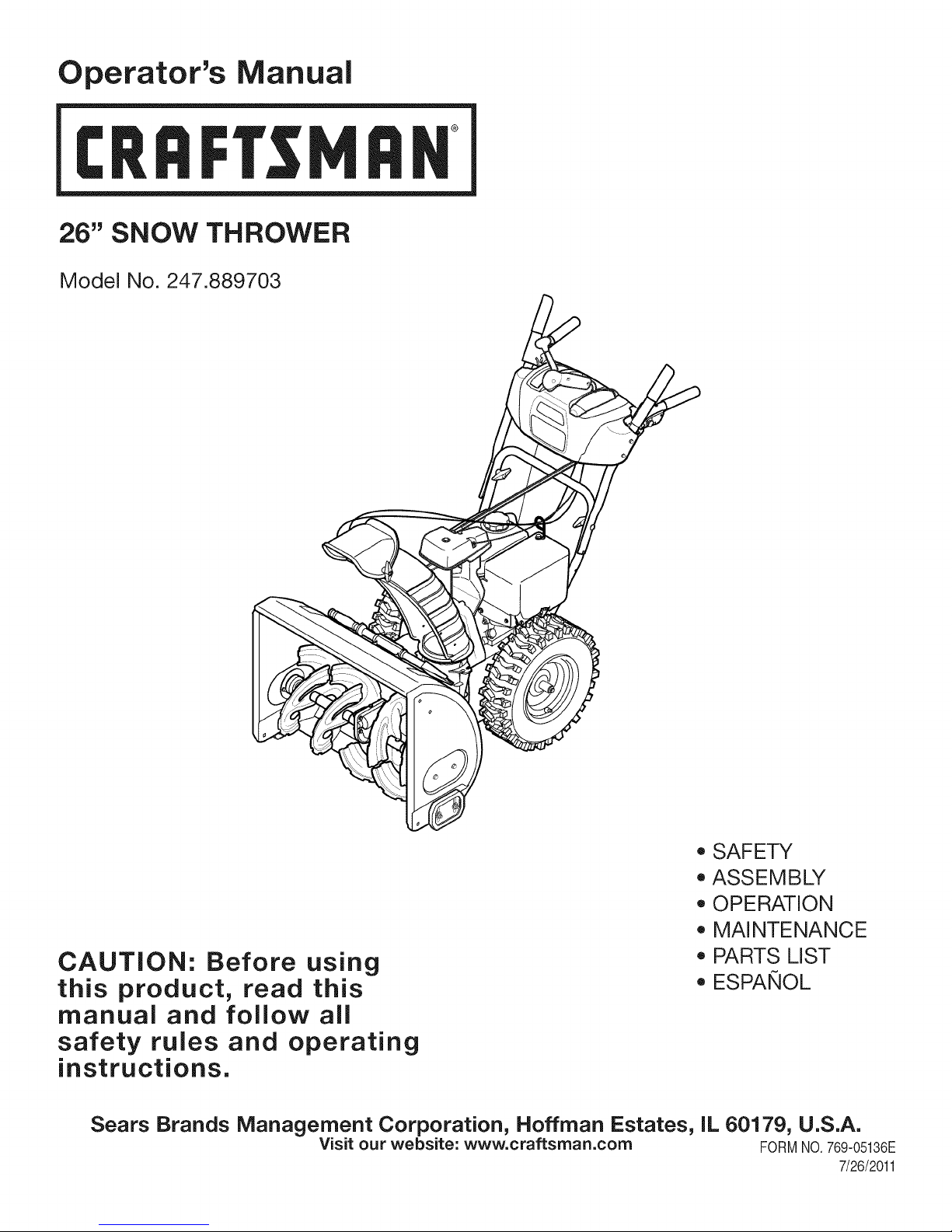
Operator's Manual
CRRFTSMRH
26" SNOW THROWER
Model No. 247.889703
CAUTION: Before using
this product, read this
manual and follow all
safety rules and operating
instructions.
Sears Brands Management Corporation, Hoffman Estates, IL 60179, U.S.A.
Visit our website: www.craftsman.com FORMNO.769-05136E
o SAFETY
ASSEMBLY
OPERATION
MAINTENANCE
PARTS LIST
o ESPANOL
7/26/2011
Page 2
WarrantyStatement.................... Page2
SafeOperationPractices.............. Pages3-6
Assembly......................... Pages8-13
Operation........................ Pages14-17
Service&Maintenance.............. Pages18-25
Off-SeasonStorage................... Page26
Troubleshooting...................... Page27
PartsList......................... Pages28-45
RepairProtectionAgreement............ Page49
Espadol............................. Page50
CRAFTSMANTWOYEARFULLWARRANTY
FORTWOYEARSfromthedateofpurchase,thisproductiswarrantedagainstanydefectsinmaterialorworkmanship.Defectiveproductwill
receivefreerepairorfreereplacementifrepairisunavailable.
Thiswarrantyisvoidifthisproductiseverusedwhileprovidingcommercialservicesorifrentedtoanotherperson.
Forwarrantycoveragedetails to obtain repairor replacement,visit the website: www.craftsman.com
This warranty covers ONLYdefects in material andworkmanship. Warrantycoverage does NOTinclude:
• Expendableitemsthatcanwearoutfromnormalusewithinthewarrantyperiod,includingbutnotlimitedtoaugers,augerpaddles,drift
cutters,skidshoes,shaveplate,shearpins,sparkplug,aircleaner,belts,andoil filter.
• Standardmaintenanceservicing,oilchanges,ortune-ups.
• Tirereplacementor repaircausedby puncturesfromoutsideobjects,suchasnails,thorns,stumps,orglass.
Tireor wheelreplacementor repairresultingfromnormalwear,accident,orimproperoperationormaintenance.
Repairsnecessarybecauseof operatorabuse,includingbutnot limitedto damagecausedbyover-speedingtheengine,or fromimpacting
objectsthatbendtheframe,augershaft,etc.
• Repairsnecessarybecauseof operatornegligence,includingbutnotlimitedto,electricalandmechanicaldamagecausedbyimproper
storage,failureto usethepropergradeandamountofengineoil, or failureto maintaintheequipmentaccordingtotheinstructionscontained
intheoperator'smanual.
• Engine(fuelsystem)cleaningorrepairscausedbyfueldeterminedto becontaminatedoroxidized(stale).Ingeneral,fuelshouldbeused
within30 daysof itspurchasedate.
Normaldeteriorationandwearoftheexteriorfinishes,orproductlabelreplacement.
Thiswarrantygivesyouspecificlegalrights,andyoumayalsohaveotherrightswhichvaryfromstatetostate.
Sears Brands Management Corporation, Hoffman Estates, IL 60179
EngineOilType: 5W-30
EngineOilCapacity: 20ounces
FuelCapacity: 2.3Quarts
SparkPlug: F6RTC
SparkPlugGap: .020"to.030"
©KCDIR LLC
Model Number.................................................................
Serial Number .................................................................
Dateof Purchase.............................................................
Recordthemodelnumber,serialnumber
anddateof purchaseabove
2
Page 3
Thissymbolpointsoutimportantsafetyinstructionswhich,if not
followed,couldendangerthepersonalsafetyand/orpropertyof
yourselfandothers. Readandfollowall instructionsin thismanual
beforeattemptingto operatethismachine.Failuretocomplywith
theseinstructionsmayresultin personalinjury.Whenyouseethis
symbol,HEEDITSWARNING!
Thismachinewasbuiltto beoperatedaccordingtothe safeopera-
tionpracticesinthis manual.As withanytypeof powerequipment,
carelessnessorerroron thepartofthe operatorcanresultin serious
injury.Thismachineiscapableofamputatingfingers,hands,toes
andfeetandthrowingdebris.Failuretoobservethe followingsafety
instructionscouldresultin seriousinjuryor death.
CALIFORNIA PROPOSITION 65
EngineExhaust,someof itsconstituents,andcertainvehicle
componentscontainoremitchemicalsknowntoStateofCalifornia
tocausecancerandbirthdefectsorotherreproductiveharm,
TRAiNiNG
• Read,understand,andfollowall instructionson themachineand
in themanual(s)beforeattemptingtoassembleandoperate.
Failuretodo socan resultinseriousinjurytothe operatorand/
orbystanders.Keepthismanualina safeplaceforfutureand
regularreferenceandfor orderingreplacementparts.
• Befamiliarwithall controlsandtheirproperoperation.Knowhow
tostopthe machineanddisengagethemquickly.
• Neverallowchildrenunder14yearsof agetooperatethis
machine.Children14andover shouldreadandunderstandthe
instructionsandsafeoperationpracticesin thismanualandon
themachineandbe trainedandsupervisedbyanadult.
Neverallowadultsto operatethis machinewithoutproper
instruction.
• Thrownobjectscancauseseriouspersonalinjury.Planyour
snow-throwingpatterntoavoiddischargeof materialtoward
roads,bystandersandthe like.
Keepbystanders,petsandchildrenat least75feetfromthe
machinewhileit is in operation.Stopmachineifanyoneenters
thearea.
• Exercisecautiontoavoidslippingorfalling,especiallywhen
operatinginreverse.
Your Responsibility--Restrict theuse of thispowermachineto
personswhoread,understandandfollowthewarningsandinstruc-
tionsin thismanualandon themachine,
SAVE THESE INSTRUCTIONS!
PREPARATION
Thoroughlyinspecttheareawherethe equipmentistobeused.
Removeall doormats,newspapers,sleds,boards,wiresandother
foreignobjects,whichcouldbe trippedoverorthrownbytheauger/
impeller.
• Alwayswearsafetyglassesoreyeshieldsduringoperationand
whileperformingan adjustmentor repairto protectyoureyes.
Thrownobjectswhichricochetcancauseseriousinjurytothe
eyes.
Donot operatewithoutwearingadequatewinteroutergarments.
Donot wearjewelry,longscarvesorotherlooseclothing,which
couldbecomeentangledinmovingparts.Wearfootwearwhich
willimprovefootingonslipperysurfaces.
Usea groundedthree-wireextensioncordand receptacleforall
machineswithelectricstartengines.
Disengageall controlleversbeforestartingtheengine.
Adjustcollectorhousingheighttocleargravelorcrushedrock
surfaces.
• Neverattemptto makeanyadjustmentswhileengineis running,
exceptwherespecificallyrecommendedintheoperator'smanual.
Letengineandmachineadjusttooutdoortemperaturebefore
startingtoclearsnow.
3
Page 4
SafeHandlingof Gasoline
Toavoidpersonalinjuryor propertydamageuseextremecarein
handlinggasoline.Gasolineisextremelyflammableandthevaporsare
explosive.Seriouspersonalinjurycanoccurwhengasolineisspilled
onyourselforyourclotheswhichcanignite.Washyourskinand
changeclothesimmediately.
• Useonlyanapprovedgasolinecontainer.
• Extinguishall cigarettes,cigars,pipesandothersources
ofignition.
• Neverfuelmachineindoors.
• Neverremovegas capor addfuel whilethe engineis hot
or running.
• Allowenginetocoolat leasttwominutesbeforerefueling.
• Neveroverfillfueltank. Filltanktono morethan1/2inch
belowbottomoffillerneckto providespaceforfuel
expansion.
• Replacegasolinecapandtightensecurely.
• Ifgasolineisspilled,wipeit offtheengineandequipment.
Movemachinetoanotherarea.Wait5 minutesbefore
startingtheengine.
• Neverstorethemachineor fuel containerinsidewhere
thereis anopenflame,sparkor pilotlight(e.g.furnace,
waterheater,spaceheater,clothesdryeretc.).
• Allowmachinetocool at least5 minutesbeforestoring.
• Neverfillcontainersinsidea vehicleor ona truckor trailer
bedwitha plasticliner.Alwaysplacecontainersonthe
groundawayfromyourvehiclebeforefilling.
• If possible,removegas-poweredequipmentfromthetruck
ortrailerand refueliton theground.Ifthisisnotpossible,
thenrefuelsuchequipmentona trailerwitha portable
container,ratherthanfromagasolinedispensernozzle.
• Keepthenozzleincontactwiththe rimof the fueltankor
containeropeningatalltimesuntil fuelingis complete.Do
notuse a nozzlelock-opendevice.
OPERATION
• Donotputhandsorfeetnear rotatingparts,inthe auger/impeller
housingorchuteassembly.Contactwiththerotatingpartscan
amputatehandsandfeet.
• Theauger/impellercontrolleveris a safetydevice.Neverbypass
itsoperation.Doingsomakesthe machineunsafeandmaycause
personalinjury.
• Thecontrolleversmustoperateeasilyin bothdirectionsand
automaticallyreturntothedisengagedpositionwhenreleased.
• Neveroperatewitha missingordamagedchuteassembly.Keep
all safetydevicesin placeandworking.
• Neverrunanengineindoorsorina poorlyventilatedarea.Engine
exhaustcontainscarbonmonoxide,anodorlessanddeadlygas.
• Donotoperatemachinewhileundertheinfluenceofalcoholor
drugs.
• Mufflerandenginebecomehotandcancausea burn.Donot
touch.Keepchildrenaway.
• Exerciseextremecautionwhenoperatingonorcrossinggravel
surfaces.Stayalertforhiddenhazardsor traffic.
• Exercisecautionwhenchangingdirectionandwhileoperatingon
slopes.Do notoperateon steepslopes.
• Planyoursnow-throwingpatternto avoiddischargetowards
windows,walls,carsetc. Thus,avoidingpossibleproperty
damageorpersonalinjurycausedbya ricochet.
• Neverdirectdischargeat children,bystandersand petsor allow
anyoneinfrontof the machine.
• Donotoverloadmachinecapacityby attemptingtoclearsnowat
toofastof arate.
• Neveroperatethis machinewithoutgoodvisibilityorlight.Always
be sureof yourfootingand keepafirmholdon thehandles.Walk,
neverrun.
• Disengagepowertotheauger/impellerwhentransportingor not
in use.
• Neveroperatemachineat hightransportspeedsonslippery
surfaces.Lookdownand behindand usecarewhenbackingup.
• Ifthe machineshouldstarttovibrateabnormally,stoptheengine,
disconnectthesparkplugwireandgroundit againstthe engine.
Inspectthoroughlyfor damage.Repairanydamagebefore
startingandoperating.
• Disengageall controlleversandstopenginebeforeyouleave
theoperatingposition(behindthehandles).Waituntiltheauger/
impellercomestoa completestopbeforeuncloggingthechute
assembly,makingany adjustments,or inspections.
• Neverput yourhandinthedischargeorcollectoropenings.Do
notunclogchuteassemblywhileengineisrunning.Shutoff
engineand remainbehindhandlesuntilall movingpartshave
stoppedbeforeunclogging.
• Useonlyattachmentsandaccessoriesapprovedbythemanufac-
turer(e.g.wheelweights,tirechains,cabsetc.).
• Whenstartingengine,pullcordslowlyuntilresistanceisfelt,then
pull rapidly.Rapidretractionofstartercord(kickback)willpull
handandarmtowardenginefasterthanyoucanletgo. Broken
bones,fractures,bruisesorsprainscouldresult.
• Ifsituationsoccurwhichare notcoveredinthis manual,usecare
andgoodjudgment.
• Forin-warrantysafety,operationormaintenancequestions,orto
orderpartsandscheduleservice,call 1-800-4-MY-HOME.
CLEARING A CLOGGED DISCHARGE CHUTE
Handcontactwiththe rotatingimpellerinsidethe dischargechute
is themostcommoncauseof injuryassociatedwithsnowthrowers.
Neveruseyourhandto cleanout thedischargechute.
Toclear thechute:
1. SHUTTHEENGINEOFF!
2. Wait 10secondstobe suretheimpellerbladeshavestopped
rotating.
3. Alwaysusea clean-outtool,notyourhands.
4
Page 5
MAINTENANCE & STORAGE
• Nevertamperwithsafetydevices.Checktheirproperoperation
regularly.Refertothe maintenanceandadjustmentsectionsof
thismanual.
• Beforecleaning,repairing,or inspectingmachinedisengageall
controlleversandstopthe engine.Waituntiltheauger/impeller
cometoa completestop.Disconnectthe sparkplugwireand
groundagainsttheenginetopreventunintendedstarting.
Checkboltsand screwsforpropertightnessatfrequentintervals
tokeepthe machineinsafeworkingcondition.Also,visually
inspectmachineforanydamage.
Donotchangetheenginegovernorsettingorover-speedthe
engine.Thegovernorcontrolsthe maximumsafeoperatingspeed
oftheengine.
Snowthrowershaveplatesandskidshoesaresubjectto wear
anddamage.Foryoursafetyprotection,frequentlycheckall
componentsand replacewithoriginalequipmentmanufacturer's
(OEM)partsonlyas listedinthe Partspagesof thisoperator's
manual.Useofpartswhichdonotmeetthe originalequipment
specificationsmayleadto improperperformanceandcompro-
misesafety!
Checkcontrolleversperiodicallytoverifytheyengageanddisen-
gageproperlyandadjust,if necessary.Referto the adjustment
sectioninthisoperator'smanualforinstructions.
Maintainor replacesafetyandinstructionlabels,as necessary.
Observeproperdisposallawsand regulationsfor gas,oil,etc.to
protecttheenvironment.
Priorto storing,runmachinea few minutestoclearsnowfrom
machineand preventfreezeupofauger/impeller.
Neverstorethemachineorfuel containerinsidewherethereisan
openflame,sparkorpilot lightsuchasa waterheater,furnace,
clothesdryeretc.
Alwaysrefertotheoperator'smanualforproperinstructionson
off-seasonstorage.
Checkfuelline,tank,cap,andfittingsfrequentlyforcracksor
leaks.Replaceif necessary.
Donotcrankenginewithsparkplugremoved.
Accordingtothe ConsumerProductsSafetyCommission(CPSC)
andtheU.S.EnvironmentalProtectionAgency(EPA),thisproduct
hasan AverageUsefulLifeof seven(7)years,or 60 hoursof
operation.Atthe endoftheAverageUsefulLifehavethemachine
inspectedannuallybyan authorizedservicedealertoensurethat
allmechanicalandsafetysystemsareworkingproperlyandnot
wornexcessively.Failuretodo socanresultinaccidents,injuries
ordeath.
DO NOT MODIFY ENGINE
Toavoidseriousinjuryor death,do not modifyengineinanyway.
Tamperingwiththegovernorsettingcanleadto a runawayengineand
causeitto operateat unsafespeeds.Nevertamperwithfactorysetting
ofenginegovernor.
NOTICE REGARDING EMiSSiONS
EngineswhicharecertifiedtocomplywithCaliforniaandfederal
EPAemissionregulationsforSORE(SmallOffRoadEquipment)are
certifiedto operateon regularunleadedgasoline,and mayinclude
thefollowingemissioncontrolsystems:EngineModification(EM),
OxidizingCatalyst(OC),SecondaryAirInjection(SAI)and ThreeWay
Catalyst(TWO)if soequipped.
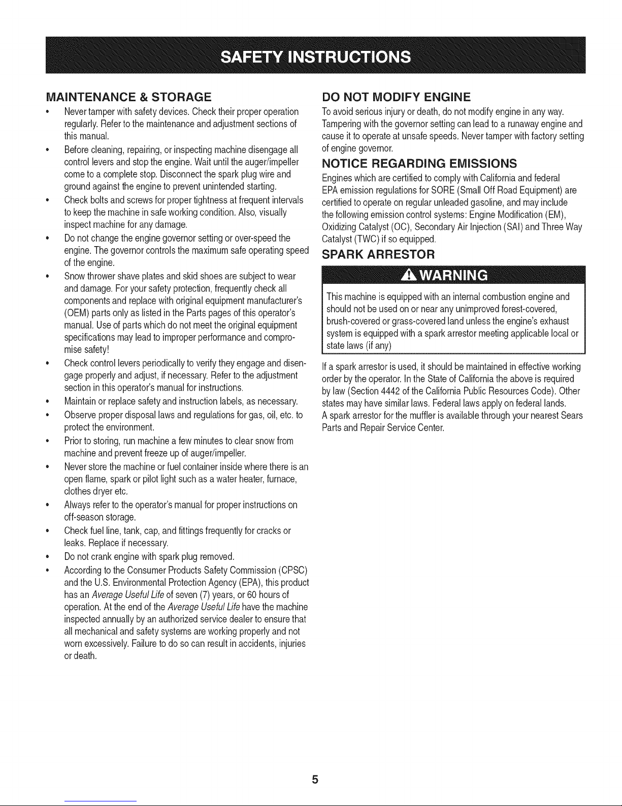
SPARK ARRESTOR
Thismachineisequippedwithaninternalcombustionengineand
shouldnotbe usedonor nearanyunimprovedforest-covered,
brush-coveredorgrass-coveredlandunlessthe engine'sexhaust
systemisequippedwitha sparkarrestormeetingapplicablelocalor
statelaws(ifany)
Ifa sparkarrestorisused,it shouldbe maintainedin effectiveworking
orderbytheoperator.IntheStateof Californiatheaboveis required
bylaw (Section4442oftheCaliforniaPublicResourcesCode).Other
statesmayhavesimilarlaws. Federallawsapplyonfederallands.
A sparkarrestorfor themuffleris availablethroughyournearestSears
PartsandRepairServiceCenter.
Page 6
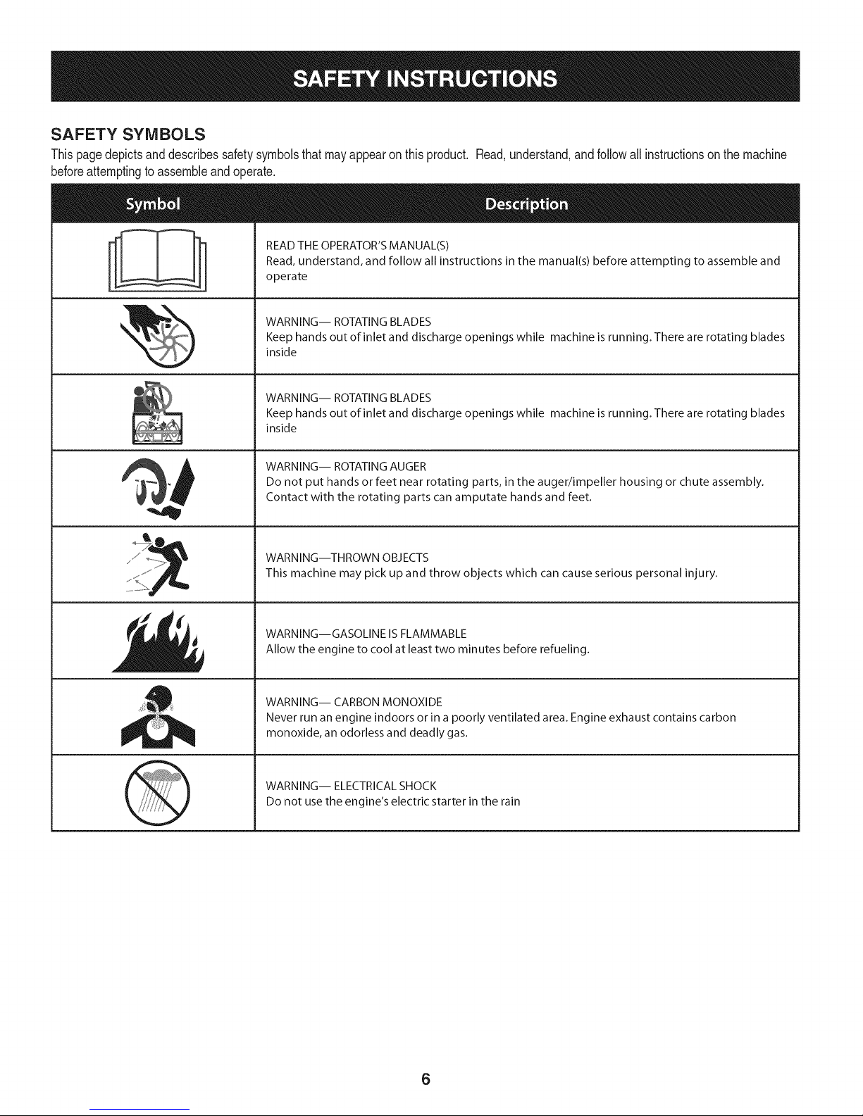
SAFETY SYMBOLS
Thispagedepictsanddescribessafetysymbolsthatmayappearonthisproduct. Read,understand,andfollowall instructionson themachine
beforeattemptingto assembleandoperate.
READ THE OPERATOR'S MANUAL(S)
i
. +
i
Read, understand, and follow all instructions in the manual(s) before attempting to assemble and
operate
WARNING-- ROTATING BLADES
Keep hands out of inlet and discharge openings while machine is running. There are rotating blades
inside
WARNING-- ROTATING BLADES
Keep hands out of inlet and discharge openings while machine is running. There are rotating blades
inside
WARNING-- ROTATING AUGER
Do not put hands or feet near rotating parts, in the auger/impeller housing or chute assembly.
Contact with the rotating parts can amputate hands and feet.
"JIp
WARNING--THROWN OBJECTS
This machine may pick up and throw objects which can cause serious personal injury.
WARNING--GASOLINE IS FLAMMABLE
Allow the engine to cool at least two minutes before refueling.
WARNING-- CARBON MONOXIDE
Never run an engine indoors or in a poorly ventilated area. Engine exhaust contains carbon
monoxide, an odorless and deadly gas+
WARNING-- ELECTRICAL SHOCK
Do not use the engine's electric starter in the rain
6
Page 7

Thispageleftintentionallyblank.
7
Page 8
NOTE:Referencesto rightorleft sideofthesnowthrowerare
determinedfrombehindtheunit intheoperatingposition(standing
directlybehindthesnowthrower,facingthe handlepanel).
REMOVING FROM CARTON
1. Cutthe cornersof thecartonandlay the sidesflaton theground.
Removeanddiscardallpackinginserts.
2. Movethesnowthroweroutofthecarton.
3. Makecertainthecartonhas beencompletelyemptiedbefore
discardingit.
ASSEMBLY
1. Observethe lowerrearareaof the snowthrowertobesureboth
cablesarealignedwith rollerguidesbeforepivotingthehandle
upward.
a. Placethe shiftleverin theF6position.
b. Pullupandbackon upperhandleasshownin Figure1.As
youare raisingthehandleupward,makesurethat bothends
ofthecentercablearepositionedproperlyinthebrackets.
Alignupperhandlewiththe lowerhandle.
c. Tightenhandknobssecuringupperhandleto lowerhandle.
Removeanddiscardany rubberbands,if present.Theyare
forpackagingpurposesonly.
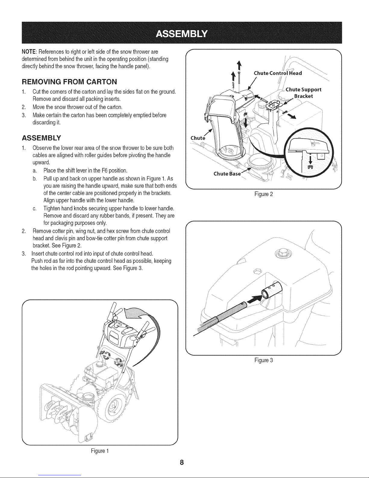
2. Removecotterpin,wing nut,andhexscrewfromchutecontrol
headandclevispinandbow-tiecotterpinfromchutesupport
bracket.SeeFigure2.
3. Insertchutecontrolrodintoinputof chutecontrolhead.
Pushrodasfarintothechutecontrolheadas possible,keeping
theholesintherod pointingupward.SeeFigure3.
Chute Control Head
_ort
Bracket
Figure2
f
I
Figure1
J
Figure3
J
8
Page 9
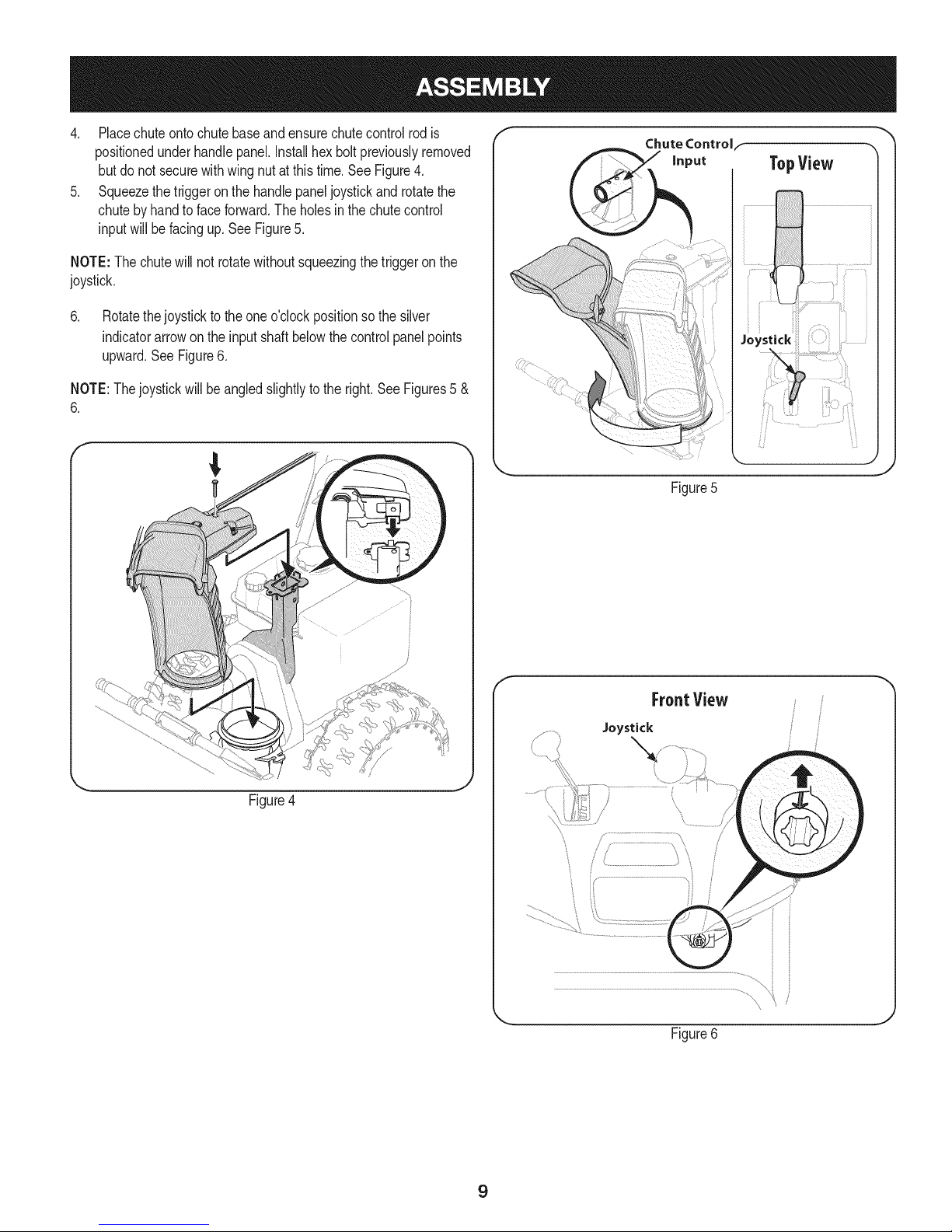
4. Placechuteontochutebaseandensurechutecontrolrodis
positionedunderhandlepanel.Installhexboltpreviouslyremoved
butdo notsecurewithwingnutatthistime.See Figure4.
5. Squeezethetriggeron the handlepaneljoystickand rotatethe
chutebyhandto faceforward.Theholesinthe chutecontrol
inputwill befacingup. SeeFigure5.
NOTE:The chutewill notrotatewithoutsqueezingthe triggeronthe
joystick.
6. Rotatethejoystickto theoneo'clockpositionsothesilver
indicatorarrowonthe inputshaftbelowthecontrolpanelpoints
upward.SeeFigure6.
NOTE:Thejoystickwillbe angledslightlyto theright.SeeFigures5 &
6.
f
Chute Controlf
Figure5
Figure4
f
FroatView
Joystick
J
Figure6
9
Page 10
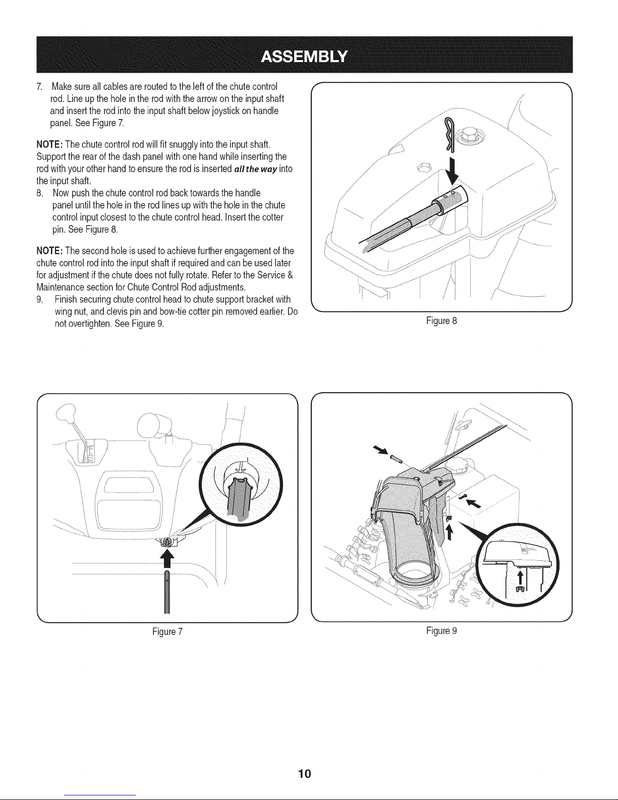
Makesureall cablesare routedtothe leftofthechutecontrol
rod.Lineupthe holein therodwiththearrowon theinputshaft
and insertthe rodintothe inputshaftbelowjoystickon handle
panel.SeeFigure7.
NOTE:The chutecontrolrodwillfit snugglyintotheinputshaft.
Supportthe rearof thedashpanelwithone handwhileinsertingthe
rodwithyourother handto ensurethe rodisinsertedallthe wey into
theinputshaft.
8. Nowpushthechutecontrolrodbacktowardsthehandle
paneluntiltheholeintherodlines upwiththeholeinthechute
controlinputclosestto the chutecontrolhead.Insertthecotter
pin.See Figure8.
NOTE:The secondholeisusedtoachievefurtherengagementofthe
chutecontrolrodintothe inputshaftif requiredandcan be usedlater
foradjustmentif thechutedoesnot fullyrotate.Refertothe Service&
MaintenancesectionforChuteControlRodadjustments.
9. Finishsecuringchutecontrolheadto chutesupportbracketwith
wingnut,andclevispin andbow-tiecotterpinremovedearlier.Do
notovertighten.See Figure9.
/i _
Figure8
y..................
\,
\
Figure7
Figure9
10
Page 11
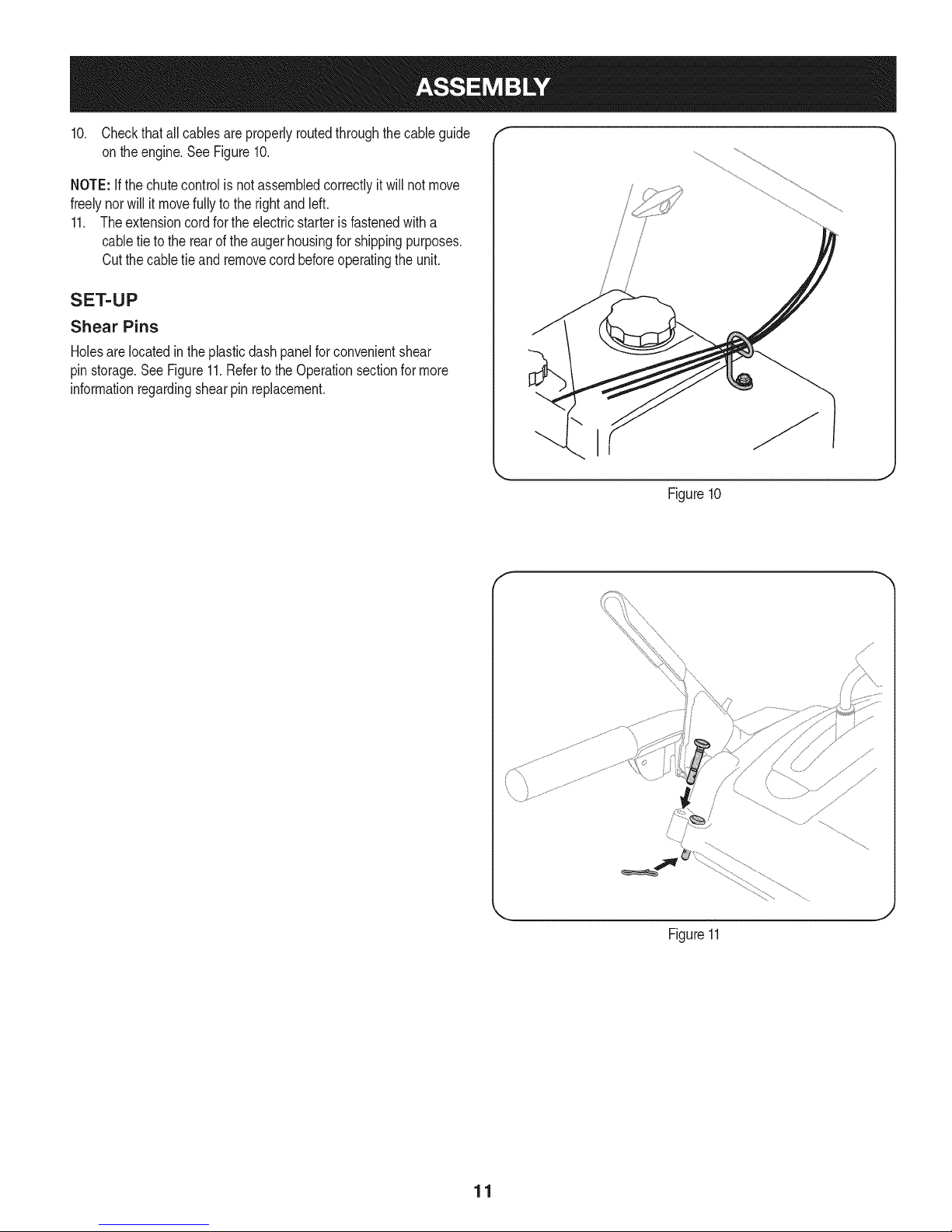
10. Checkthatallcablesareproperlyroutedthroughthecable guide
on theengine.SeeFigure10.
NOTE:ifthechutecontrolisnotassembledcorrectlyitwillnot move
freelynorwillit movefullyto therightandleft.
11. Theextensioncordforthe electricstarterisfastenedwitha
cabletie to therearof theaugerhousingforshippingpurposes.
Cutthecabletie and removecordbeforeoperatingthe unit.
SET-UP
Shear Pins
Holesare locatedintheplasticdashpanelforconvenientshear
pinstorage.SeeFigure11.RefertotheOperationsectionfor more
informationregardingshearpin replacement.
,iiiiiii!,! ii_ili
iiii 1
/
/
i I
/
M
Figure10
J
Figure11
11
Page 12
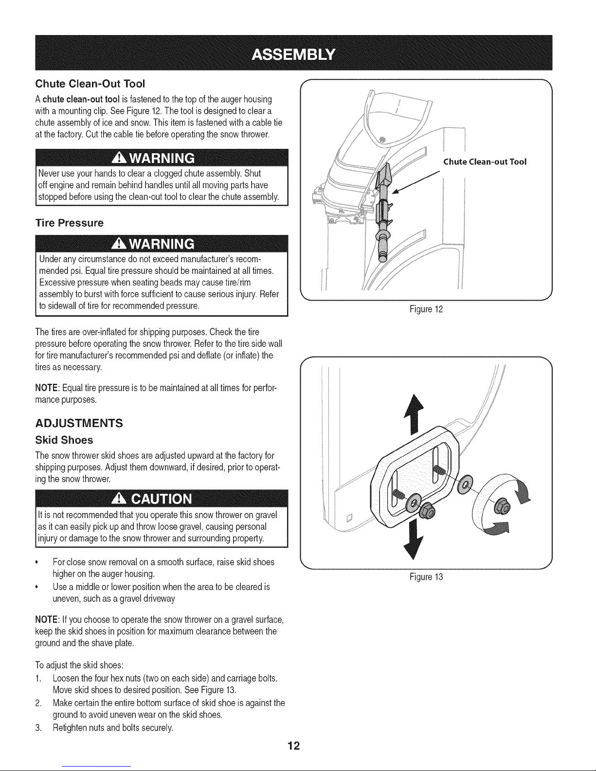
Chute Clean=Out Tool
Achute clean-out tool isfastenedtothe top oftheaugerhousing
witha mountingclip.SeeFigure12.Thetool isdesignedtocleara
chuteassemblyoficeandsnow.Thisitemisfastenedwitha cabletie
atthefactory.Cutthecable tiebeforeoperatingthesnowthrower.
loff ving partshave
stoppedbeforeusingtheclean-outtoolto clear thechuteassembly.
Tire Pressure
Underanycircumstancedo notexceedmanufacturer'srecom-
mendedpsi.Equaltire pressureshouldbe maintainedat all times.
Excessivepressurewhenseatingbeadsmaycausetire/rim
assemblytoburstwithforcesufficienttocauseseriousinjury.Refer
tosidewallof tirefor recommendedpressure.
Thetiresareover-inflatedforshippingpurposes.Checkthetire
pressurebeforeoperatingthe snowthrower.Refertothetiresidewall
fortiremanufacturer'srecommendedpsianddeflate(or inflate)the
tiresasnecessary.
Chute Clean=out Tool
Figure12
NOTE:Equaltire pressureisto be maintainedat alltimesfor perfor-
mancepurposes.
ADJUSTMENTS
Skid Shoes
Thesnowthrowerskidshoesareadjustedupwardatthefactoryfor
shippingpurposes.Adjustthemdownward,ifdesired,priorto operat-
ingthesnowthrower.
It is notrecommendedthatyouoperatethissnowthrowerongravel
asitcaneasilypickup andthrowloosegravel,causingpersonal
njuryordamageto thesnowthrowerand surroundng property.
• Forclosesnowremovalona smoothsurface,raiseskidshoes
higherontheaugerhousing.
• Usea middleorlowerpositionwhentheareatobe clearedis
uneven,suchas a graveldriveway
NOTE:If youchoosetooperatethesnowthrowerona gravelsurface,
keepthe skidshoesin positionformaximumclearancebetweenthe
groundandtheshaveplate.
Toadjustthe skidshoes:
1. Loosenthefour hexnuts(twooneachside)andcarriagebolts.
Moveskidshoestodesiredposition.SeeFigure13.
2. Makecertaintheentirebottomsurfaceof skidshoeis againstthe
groundtoavoidunevenwearontheskidshoes.
3. Retightennutsand boltssecurely.
Figure13
12
Page 13
Auger Control
Priortooperatingyoursnowthrower,carefullyreadandfollowall
instructionsbelow.Performalladjustmentsto verifyyoursnow
throwerisoperatingsafelyandproperly.
Checktheadjustmentof theaugercontrolasfollows:
1. Whentheaugercontrolis releasedandin the disengaged"up"
position,thecableshouldhavevery littleslack.ItshouldNOTbe
tight.
2. Ina well-ventilatedarea,startthesnowthrowerengine.Refer
toStartingtheEngineinthe Operationsection.Makesurethe
throttleis setin theFASTposition.
3. Whilestandingintheoperator'sposition(behindthe snow
thrower),engagethe augers.
4. Allowtheaugersto remainengagedforapproximatelyten(10)
secondsbeforereleasingthe augercontrol.Repeatthisseveral
times.
5. Withtheaugercontrolin thedisengaged"up"position,walktothe
frontofthe machine.
6. Confirmthatthe augershavecompletelystoppedrotatingand
showNOsignsof motion.If anyaugershowsANYsignof
rotating,immediatelyreturntotheoperator'spositionandshutoff
theengine.WaitforALLmovingpartstostopbeforeadjustingthe
augercontrol.
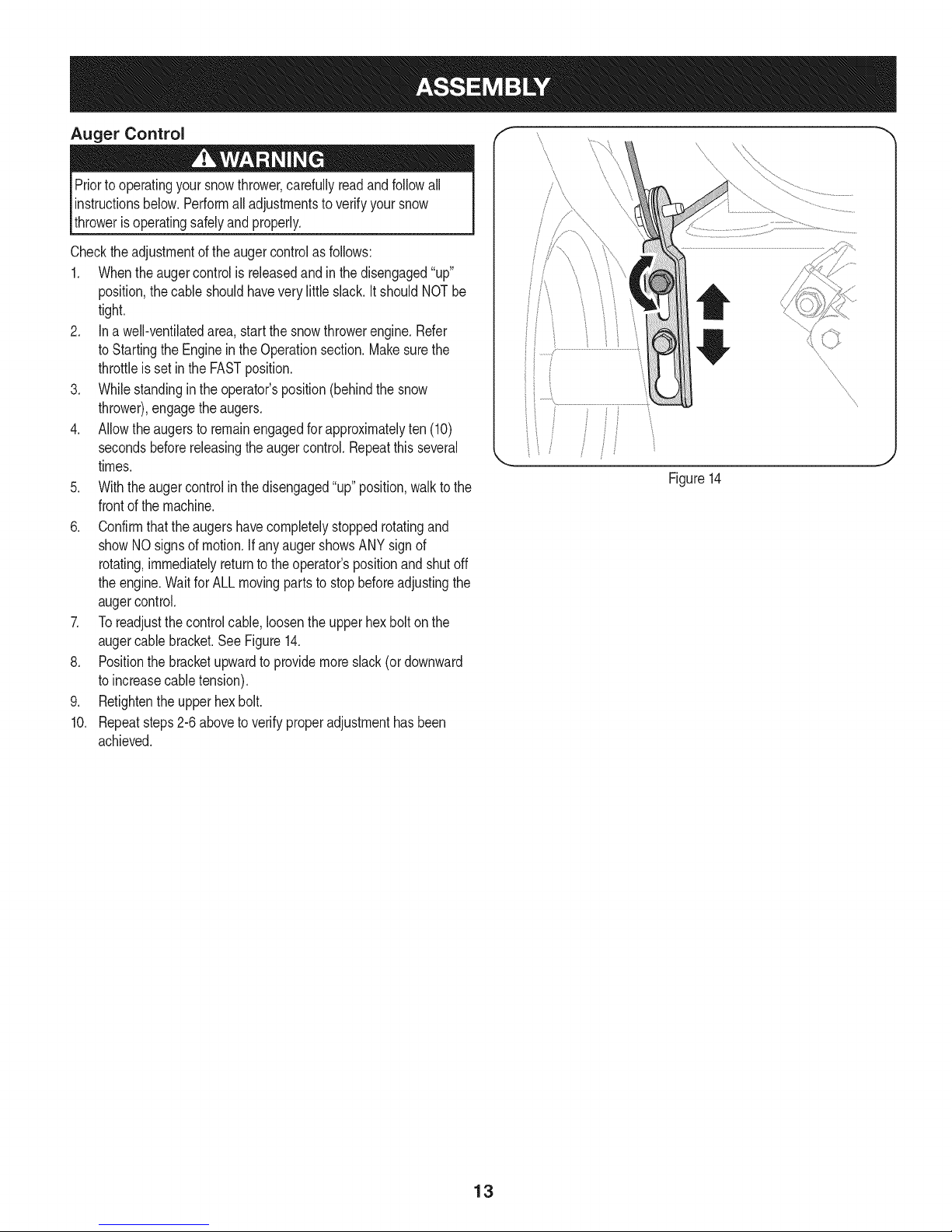
7. Toreadjustthecontrolcable,loosentheupperhexbolt onthe
augercablebracket.SeeFigure14.
8. Positionthe bracketupwardtoprovidemoreslack(or downward
toincreasecabletension).
9. Retightentheupperhexbolt.
10. Repeatsteps2-6aboveto verifyproperadjustmenthasbeen
achieved.
Figure14
\
\
\
\
\
\
13
Page 14
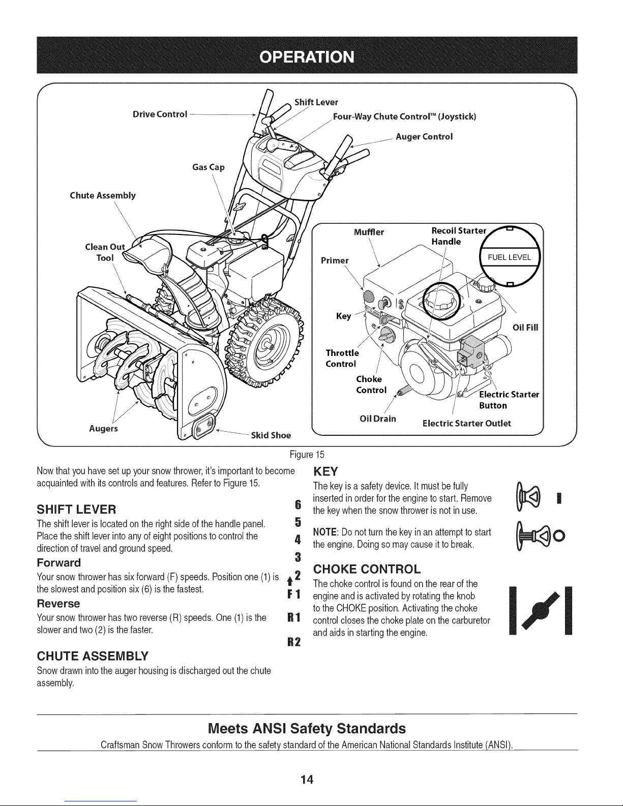
f
Drive Control
Gas Cap
Chute Assembly
Clean Out
Tool
\
\
Augers
Skid Shoe
Figure15
Nowthat youhavesetup yoursnowthrower,it'simportanttobecome
acquaintedwith itscontrolsandfeatures.RefertoFigure15.
SHIFT LEVER 6
Theshiftleveris locatedonthe rightsideofthehandlepanel. 5
Placethe shiftleverintoanyofeightpositionstocontrolthe 4
directionoftravelandgroundspeed.
Forward 3
Yoursnowthrowerhassixforward(F) speeds.Positionone(1)is t 2
theslowestand positionsix (6) isthe fastest. F 1
Reverse
Yoursnowthrowerhastwo reverse(R)speeds.One(1)is the
slowerandtwo(2) is the faster.
Shift Lever
/ Four=Way Chute Control" (Joystick)
J
Auger Control
Mumer Recoil Starter
\ Handle
Primer ___. FUEL LEVEL
\
\
Key
Throttle
Control
Choke
Control
/
Oil Drain
KEY
Thekeyis a safetydevice.It mustbefully
insertedinorderforthe engineto start, Remove
thekeywhenthesnowthrowerisnot in use,
NOTE:Donot turnthe keyinan attemptto start
theengine.Doingsomaycauseit tobreak.
CHOKE CONTROL
Thechokecontrolisfoundon therearofthe
engineand is activatedbyrotatingtheknob
totheCHOKEposition.Activatingthechoke
controlclosesthe chokeplateon thecarburetor
andaidsin startingtheengine.
Electric Starter Outlet
Electric Starter
Button
,J
CHUTE ASSEMBLY
Snowdrawnintotheaugerhousingisdischargedoutthechute
assembly.
Meets ANSi Safety Standards
CraftsmanSnowThrowersconformto thesafetystandardof the AmericanNationalStandardsInstitute(ANSi).
14
Page 15
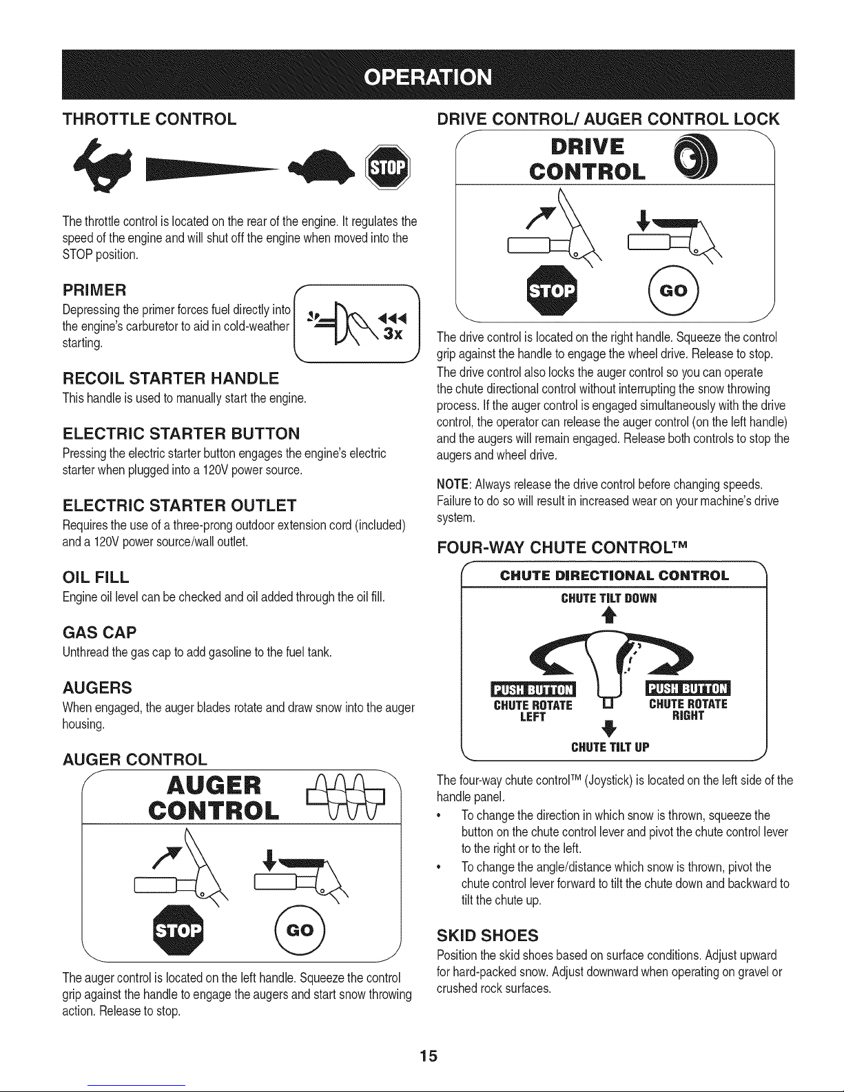
THROTTLE CONTROL
Thethrottlecontrolis locatedon therearof the engine.It regulatesthe
speedof theengineandwillshutoff theenginewhenmovedintothe
STOPposition.
DRIVE CONTROL/AUGER CONTROL LOCK
f DRIVE
CONTROL
Depressingthe primerforcesfuel directlyinto _p
theengine'scarburetorto aid incold-weather
starting.
RECOIL STARTER HANDLE
Thishandleisusedto manuallystarttheengine.
ELECTRIC STARTER BUTTON
Pressingtheelectricstarterbuttonengagestheengine'selectric
starterwhenpluggedintoa 120Vpowersource.
ELECTRIC STARTER OUTLET
Requirestheuseof athree-prongoutdoorextensioncord(included)
anda 120Vpowersource/walloutlet.
OIL FILL
Engineoil levelcanbecheckedand oiladdedthroughtheoil fill.
GAS CAP
Unthreadthegascaptoaddgasolinetothe fuel tank.
AUGERS
Whenengaged,theaugerbladesrotateanddrawsnowintothe auger
housing.
AUGER CONTROL
f AUGER
CONTROL
@
Thedrivecontrolis locatedon therighthandle.Squeezethecontrol
gripagainstthehandleto engagethe wheeldrive.Releasetostop.
Thedrivecontrolalso lockstheaugercontrolso youcan operate
thechutedirectionalcontrolwithoutinterruptingthesnowthrowing
process.If theaugercontrolisengagedsimultaneouslywiththedrive
control,the operatorcanreleasetheaugercontrol(onthelefthandle)
andtheaugerswillremainengaged.Releasebothcontrolstostopthe
augersandwheeldrive.
NOTE:Alwaysreleasethedrivecontrolbeforechangingspeeds.
Failureto dosowillresultinincreasedwearon yourmachine'sdrive
system.
FOUR-WAY CHUTE CONTROL TM
f
CHUTE DiRECTiONAL CONTROL
CHUTETiLTDOWH
t
CHUTEROTATE CHUTEROTATE
LEFT RIGHT
CHUTETiLTUP
Thefour-waychutecontroFM(Joystick)islocatedon theleft sideof the
handlepanel.
* Tochangethedirectioninwhichsnowisthrown,squeezethe
buttononthechutecontrolleverandpivotthechutecontrollever
tothe rightorto theleft.
* Tochangetheangle/distancewhichsnowisthrown,pivotthe
chutecontrolleverforwardtotiltthe chutedownandbackwardto
tilt the chuteup.
Theaugercontrolislocatedonthe left handle.Squeezethecontrol
gripagainstthehandleto engagetheaugersandstart snowthrowing
action.Releasetostop.
SKID SHOES
Positiontheskidshoesbasedonsurfaceconditions.Adjustupward
forhard-packedsnow.Adjustdownwardwhenoperatingon gravelor
crushedrocksurfaces.
15
Page 16

CLEAN-OUT TOOL
Neveruseyourhandstocleara cloggedchuteassembly.Shut
off engineandremainbehindhandlesuntilall movingpartshave
stoppedbeforeusingtheclean-outtoolto clearthechuteassembly.
Thechuteclean-outtoolis convenientlyfastenedtotherearofthe
augerhousingwitha mountingclip.Shouldsnowandicebecome
lodgedin thechuteassemblyduringoperation,proceedasfollowsto
safelycleanthechuteassemblyandchuteopening:
1. Releaseboththe AugerControlandtheDriveControl.
2. Stopthe enginebyremovingthe ignitionkey.
3. Removetheclean-outtoolfromtheclipwhichsecuresitto the
rearofthe augerhousing.
4. Usethe shovel-shapedendof theclean-outtooltodislodgeand
scoopanysnowand icewhichhasformedin andnearthechute
assembly.
5. Refastenthe clean-outtooltothe mountingclipontherearof
theaugerhousing,reinserttheignitionkeyandstartthesnow
thrower'sengine.
6. Whilestandingintheoperator'sposition(behindthesnow
thrower),engagethe augercontrolfora fewsecondstoclear any
remainingsnowandice fromthechuteassembly.
BEFORE STARTING ENGINE
Read,understand,andfollowall instructionsandwarningson the
machineand inthismanualbeforeoperating.
Oil
Theunit wasshippedwith oil inthe engine.Checkoillevelbefore
eachoperationtoensureadequateoil intheengine.Forfurther
instructions,refertothe stepson page18.
NOTE:Besureto checkthe engineon a levelsurfacewiththe engine
stopped.
1. Removetheoil fillercap/dipstickandwipethe dipstickclean.
2. insertthecap/dipstickintothe oilfillerneck,andtightenthe cap
untilseated.
3. Removetheoil fillercap/dipstick,ifthelevelislow,slowlyadd
oil (5%30, witha minimumclassificationof SF/SG)untiloil level
registersbetweenhigh(H) andlow(L).
NOTE:Do notoverfill.Overfillingwithoil mayresultinenginesmoking,
hardstartingorsparkplugfouling.
4. Replaceandtightencap/dipstickfirmlybeforestartingengine.
Gasoline
Useautomotivegasoline(unleadedor lowleadedtominimizecombus-
tionchamberdeposits)witha minimumof87octane.Gasolinewith
upto 10%ethanolor 15%MTBE(MethylTertiaryButylEther)canbe
used.Neveruseanoil/gasolinemixtureor dirtygasoline.Avoidgetting
dirt,dust,or waterinthefueltank.DONOTuse E85gasoline.
• Refuelina well-ventilatedareawiththeenginestopped.Donot
smokeorallowflamesor sparksinthe areawheretheengineis
refueledor wheregasolineisstored.
• Donotoverfillthefueltank.After refueling,makesurethetank
capisclosedproperlyandsecurely.
• Becarefulnotto spillfuelwhenrefueling.Spilledfuelorfuelvapor
mayignite,ifany fuelis spilled,makesurethe areaisdrybefore
startingthe engine.
• Avoidrepeatedorprolongedcontactwithskinor breathingof
)or.
Useextremecarewhenhandlinggasoline.Gasolineisextremely
flammableandthevaporsare explosive.Neverfuelthe machine
indoorsorwhiletheengineishotor running.Extinguishcigarettes,
cigars,pipesandothersourcesof ignition.
1. Cleanaroundfuel fill beforeremovingcap to fuel.
2. A fuellevelindicatorislocatedinthefueltank.SeeFigure15
inset.Becarefulnottooverfill.Filltank untilfuel reachesthefuel
levelindicatortoallowspaceforfuelexpansion.
STARTING THE ENGINE
Alwayskeephandsandfeetclearof movingparts.Donotusea
pressurizedstartingfluid.Vaporsareflammable.
NOTE:Allowtheengineto warmupfor a fewminutesafter starting.
Theenginewillnotdevelopfullpoweruntilitreachesoperating
temperatures.
1. Makecertainboththe augercontrolanddrivecontrolarein the
disengaged(released)position.
2. insertignitionkeyinto slot.Makesure itsnapsintoplace.Donot
attempttoturnthekey.
NOTE:Theenginecannotstartwithoutthe keyisfully insertedintothe
ignitionswitch.
Electric Starter
Theoptionalelectricstarterisequippedwitha groundedthree-wire
powercordand plug,andisdesignedtooperateon 120voltAC
householdcurrent.Itmustbe usedwitha properlygroundedthree-
prongreceptacleat all timestoavoidthepossibilityofelectricshock.
Followall instructionscarefullypriorto operatingtheelectricstarter.
DONOTuseelectricstarterinthe rain.
Determinethatyourhome'swiringis a three-wiregroundedsystem.
Aska licensedelectricianifyou arenotcertain.
Ifyou havea groundedthree-prongreceptacle,proceedasfollows.
Ifyou donothavetheproperhousewiring,DONOTusetheelectric
starterunderanyconditions.
1. Plugtheextensioncordintotheoutletlocatedon the engine's
surface.Plugtheotherendof extensioncordintoa three-prong
120-volt,grounded,ACoutletina well-ventilatedarea.
16
Page 17
2. MovethrottlecontroltoFAST(rabbit)_ position.
3. MovechoketotheCHOKEI,"1pos t /co denginestart).If
engineiswarm,placechokein RUNposition.
4. Pushprimerthree(3)times,makingsuretocoverventholewhen
pushing.Ifengineiswarm,pushprimeronlyonce.Alwayscover
ventholewhenpushing.Coolweathermayrequireprimingtobe
repeated.
5. Pushstarterbuttonto start engine.Oncetheenginestarts,im-
mediatelyreleasestarterbutton.Electricstarteris equippedwith
thermaloverloadprotection;systemwilltemporarilyshut-downto
allowstartertocool if electricstarterbecomesoverloaded.
6. Astheenginewarms,slowlyrotatethe chokecontroltoRUN
position.Iftheenginefalters,restartengineandrunwithchoke
athalf-chokepositionfor a shortperiodoftime,andthen slowly
rotatethechokeintoRUNposition.
7. Afterengineis running,disconnectpowercordfromelectric
starter.Whendisconnecting,alwaysunplugtheendat the wall
outletbeforeunpluggingtheoppositeendfromthe engine.
Recoil Starter
Donotpullthestarterhandlewhiletheenginerunning.
1. Movethrottlecontrolto FAST(rabbit)_ position.
2. MovechoketotheCHOKEJ..#Jposition(coldenginestart).If
engineiswarm,placechokein RUNposition.
3. Pushprimerthree(3)times,makingsuretocoverventholewhen
pushing.Ifengineiswarm,pushprimeronlyonce.Alwayscover
ventholewhenpushing.Coolweathermayrequireprimingtobe
repeated.
4. Pullgentlyonthe starterhandleuntilitbeginstoresist,then
pullquicklyandforcefullytoovercomethecompression.Engine
shouldstart.Donot releasethehandleandallow ittosnapback.
ReturnropeSLOWLYtooriginalposition.If required,repeatthis
step.
5. Astheenginewarms,slowlyrotatethe chokecontroltoRUN
position.Iftheenginefalters,restartengineandrunwithchoke
athalf-chokepositionfor a shortperiodoftime,andthen slowly
rotatethechokeintoRUNposition.
TO ENGAGE DRIVE
1. Withthethrottlecontrolinthe Fast(rabbit) '_ position,move
shiftleverintooneof thesix forward(F)positionsortwo reverse
(R)positions.Selecta speedappropriatefor thesnowconditions
anda paceyou'recomfortablewith.
NOTE:Whenselectinga DriveSpeed,use the slowerspeedsuntil
youarecomfortableandfamiliarwiththe operationofthesnow
thrower.
2. Squeezethedrivecontrolagainstthehandleandthesnow
throwerwillmove.Releaseit anddrivemotionwillstop.
NOTE:NEVERrepositionthe shiftlever(changespeedsordirection
oftravel)withoutfirst releasingthe drivecontrolandbringingthesnow
throwertoa completestop.Doingsowill resultinprematurewearto
thesnowthrower'sdrivesystem.
TO ENGAGE AUGERS
1. Toengagethe augersandstartthrowingsnow,squeezethe
augercontrolagainstthelefthandle.Releasetostoptheaugers.
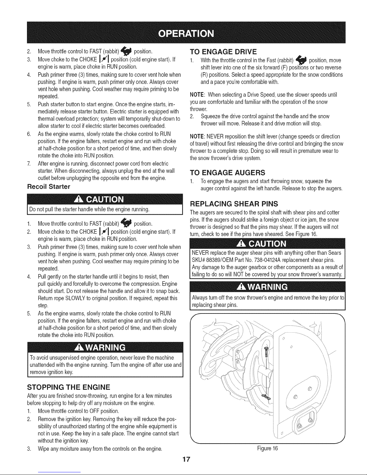
REPLACING SHEAR PINS
Theaugersaresecuredto thespiralshaftwith shearpinsandcotter
pins.If the augersshouldstrikeaforeignobjectorice jam,thesnow
throwerisdesignedsothatthepinsmayshear.If theaugerswill not
turn,checktoseeifthe pins havesheared.SeeFigure16.
NEVERreplacethe augershearpinswithanythingotherthanSears
SKU#88389/0EMPartNo.738-04124Areplacementshearpins.
Anydamagetotheaugergearboxorothercomponentsasa resultof
[fa ngto doso w NOTbe coveredbyyoursnowthrowers warranty.
Alwaysturnoff the snowthrower'sengineandremovethekeypriorto
replacingshearpins.
o
Toavoid unsupervisedengineoperation,neverleavethemachine
unattendedwiththeenginerunning.Turntheengineoffafteruseand
removeignitionkey.
STOPPING THE ENGINE
Afteryouarefinishedsnow-throwing,runenginefora fewminutes
beforestoppingtohelpdry offanymoistureontheengine.
1. Movethrottlecontrolto OFFposition.
2. Removetheignitionkey.Removingthekeywill reducethepos-
sibilityof unauthorizedstartingof theenginewhileequipmentis
notinuse.Keepthekeyin a safeplace.Theenginecannotstart
withouttheignitionkey.
3. Wipeanymoistureawayfromthecontrolsontheengine.
iJ
Figure16
17
Page 18
MAINTENANCE SCHEDULE
Beforeperforminganytypeofmaintenance/service,disengageall
controlsandstoptheengine.Waituntilallmovingpartshavecometo
acompletestop.Disconnectsparkplugwireandgrounditagainstthe
enginetopreventunintendedstarting.Alwayswearsafetyglassesduring
operationor whileperforminganyadjustmentsor repairs.
EachUseandevery5
hours
1st5 hours
Annuallyor25hours
Annuallyor50hours
Annuallyor100hours
BeforeStorage
1. Engineoillevel
2. Looseormissinghardware
3. Unitandengine.
1. Engineoil
1. Sparkplug
2. Controllinkagesand pivots
3. Wheels
4. GearshaftandAugershaft
5. 4-WayChuteControlTM
1. Engineoil
1. Sparkplug
1. Fuelsystem
1. Check
2. Tightenor replace
3. Clean
1. Change
1. Check
2. Lubewithlightoil
3. Lubewithmultipurposeautogrease
4. Lubewithlightoil
5. Checkfor cableslackness
1. Change
1. Change
1. Runengineuntilit stopsfromlack
Followthemaintenanceschedulegivenbelow.Thischartdescribes
serviceguidelinesonly.UsetheServiceLogcolumntokeeptrackof
completedmaintenancetasks.To locate the nearestSearsService
Centeror toscheduleservice,simplycontactSearsat
1-800-4-MY-HOME®.
offuel
ENGINE MAINTENANCE
Beforelubricating,repairing,or inspecting,disengageall controls
Iandstopengine.Waituntilall movingpartshavecometo acomplete
_stop.
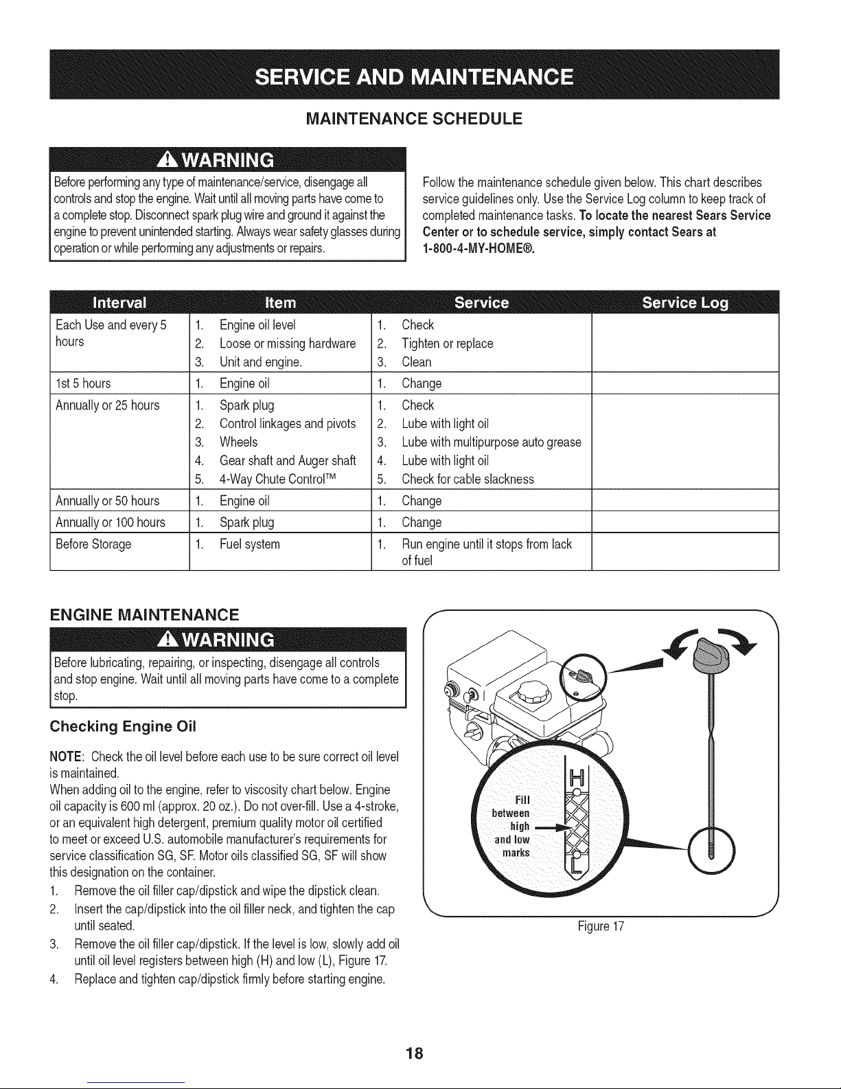
Checking Engine Oil
NOTE: Checktheoil levelbeforeeachuseto besurecorrectoil level
ismaintained.
Whenaddingoiltotheengine,referto viscositychart below.Engine
oilcapacityis 600ml (approx.20oz.).Donotover-fill.Usea4-stroke,
oran equivalenthighdetergent,premiumqualitymotoroilcertified
tomeetorexceedU.S.automobilemanufacturer'srequirementsfor
serviceclassificationSG, SR MotoroilsclassifiedSG, SFwill show
thisdesignationonthecontainer.
1. Removetheoil fillercap/dipstickandwipethe dipstickclean.
2. Insertthe cap/dipstickintothe oilfillerneck,andtightenthe cap
untilseated.
3. Removetheoil fillercap/dipstick.Ifthe levelis low,slowlyaddoil
untiloil levelregistersbetweenhigh(H)and low(L),Figure17.
4. Replaceandtightencap/dipstickfirmlybeforestartingengine.
f
Figure17
18
Page 19
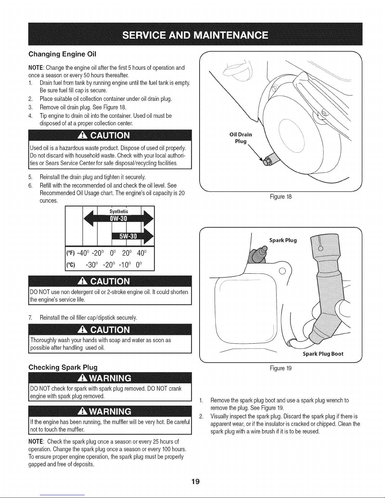
Changing Engine Oil
NOTE:Changetheengineoilafterthefirst5hoursof operationand
oncea seasonorevery50hoursthereafter.
1. Drainfuelfromtankbyrunningengineuntilthefueltankisempty.
Besurefuelfillcapis secure.
2. Placesuitableoilcollectioncontainerunderoildrainplug.
3. Removeoildrainplug.SeeFigure18.
4. Tipenginetodrainoil intothecontainer.Usedoilmustbe
disposedofat a propercollectioncenter.
Usedoil isa hazardouswasteproduct.Disposeof usedoil properly.
Donotdiscardwith householdwaste.Checkwithyourlocalauthori-
tiesor SearsServiceCenterforsafedisposal/recyclingfacilities.
.
Reinstallthedrainplugandtightenit securely.
6.
Refillwiththerecommendedoil andchecktheoil level.See
RecommendedOil Usagechart.Theengine'soil capacityis 20
ounces.
u i
Synthetic
Oil Drain
Plug
_=, ,J
Figure18
(0F)-40o-20 o 0o 200 400
("c) -30° -20° -10° 0°
DONOTuse nondetergentoilor 2-strokeengineoil.It couldshorten
theengine'sservicelife.
7. Reinstalltheoilfillercap/dipsticksecurely.
Thoroughlywashyourhandswithsoapandwateras soonas
possibleafterhandling usedoil.
Checking Spark Plug
DONOTcheckfor sparkwithsparkplugremoved.DONOTcrank
enginewithsparkplugremoved.
Iftheenginehasbeenrunning,themufflerwillbevery hot.Becareful
notto touchthemuffler.
NOTE: Checkthesparkplugoncea seasonorevery25hoursof
operation.Changethesparkplugoncea seasonor every100hours.
Toensureproperengineoperation,the sparkplugmustbe properly
gappedandfreeofdeposits.
Spark Plug
©
J
Figure19
1. Removethesparkplugbootand usea sparkplugwrenchto
removetheplug.SeeFigure19.
2. Visuallyinspectthe sparkplug.Discardthe sparkplugif thereis
apparentwear,oriftheinsulatoriscrackedorchipped.Cleanthe
sparkplugwithawirebrushifit istobe reused.
19
Page 20
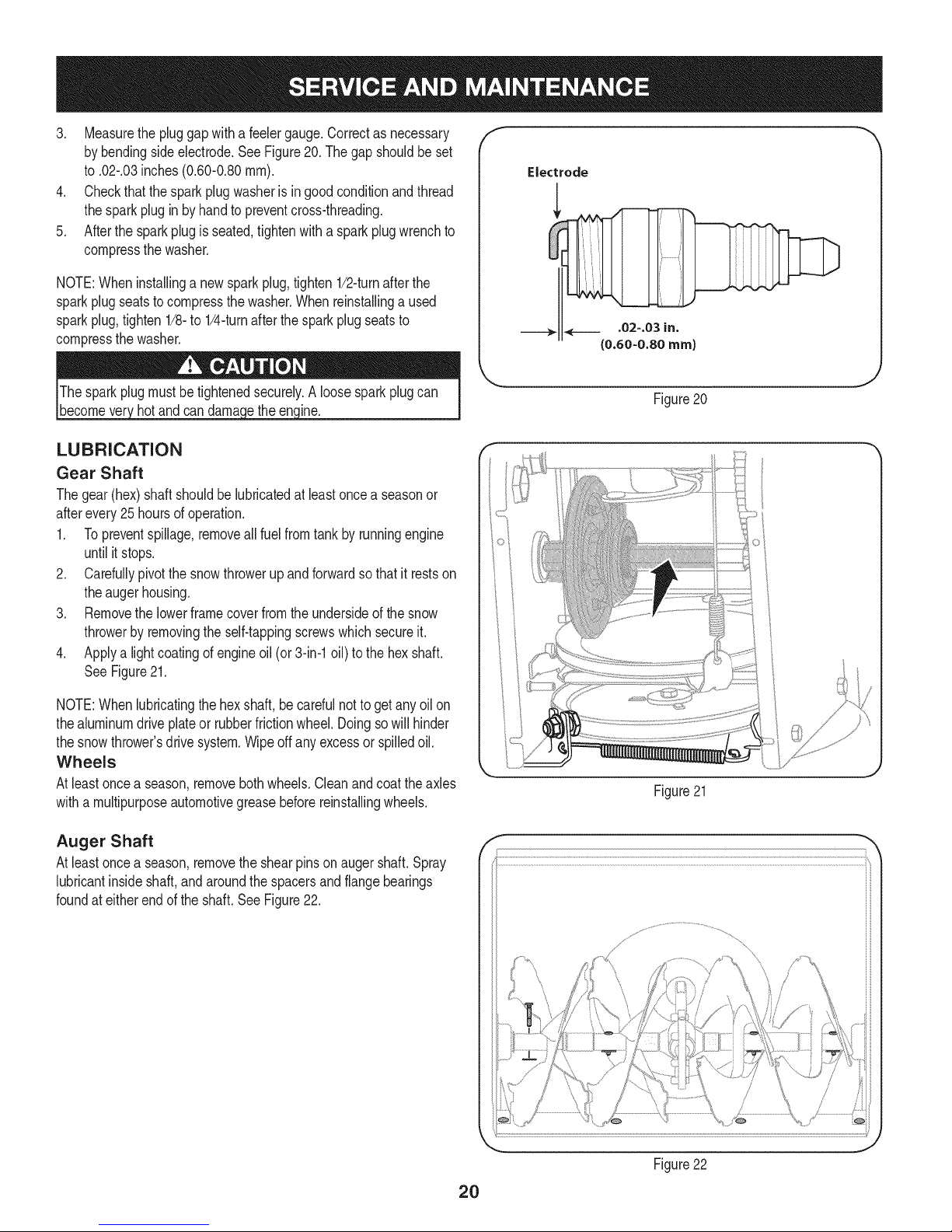
3. Measurethe pluggapwitha feelergauge.Correctas necessary
bybendingsideelectrode.SeeFigure20.Thegap shouldbeset
to.02-.03inches(0.60-0.80ram).
4. Checkthatthesparkplugwasherisingoodconditionandthread
thesparkplugin byhandto preventcross-threading.
5. Afterthe sparkplugisseated,tightenwitha sparkplugwrenchto
compressthewasher.
NOTE:Wheninstallinga newsparkplug,tighten1/2-turnafterthe
sparkplugseatstocompressthe washer.Whenreinstallinga used
sparkplug,tighten1/8-to 1/4-turnafterthesparkplugseatsto
compressthewasher.
hotandcan ine.
LUBRICATION
Gear Shaft
Thegear(hex)shaft shouldbelubricatedatleastoncea seasonor
afterevery25 hoursofoperation.
1. Topreventspillage,removeall fuel fromtank by runningengine
untilitstops.
2. Carefullypivotthesnowthrowerupandforwardsothat it restson
theaugerhousing.
3. Removethe lowerframecoverfromtheundersideofthe snow
throwerbyremovingtheself-tappingscrewswhichsecureit.
4. Applya lightcoatingofengineoil (or3-in-1oil) to thehexshaft.
SeeFigure21.
f
J
Figure20
NOTE:Whenlubricatingthehexshaft,be carefulnottogetany oilon
thealuminumdriveplateor rubberfrictionwheel.Doingsowillhinder
thesnowthrower'sdrivesystem.Wipeoffanyexcessor spilledoil.
Wheels
Atleastoncea season,removebothwheels.Cleanandcoattheaxles
witha multipurposeautomotivegreasebeforereinstallingwheels.
Auger Shaft
Atleastoncea season,removethe shearpinson augershaft.Spray
lubricantinsideshaft,andaroundthespacersandflangebearings
foundat eitherendoftheshaft.SeeFigure22.
Figure21
f
\
J
Figure22
2O
Page 21
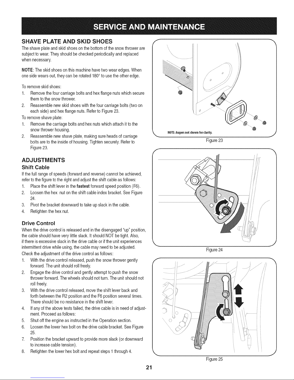
SHAVE PLATE AND SKiD SHOES
Theshaveplateand skidshoesonthebottomofthesnowthrowerare
subjectto wear.Theyshouldbecheckedperiodicallyandreplaced
whennecessary.
NOTE:Theskidshoesonthismachinehavetwowearedges.When
onesidewearsout, theycanbe rotated1800to usetheotheredge.
Toremoveskidshoes:
1. Removethefourcarriageboltsandhexflangenutswhichsecure
themtothe snowthrower.
2. Reassemblenewskidshoeswiththefourcarriagebolts(twoon
eachside)and hexflangenuts.Referto Figure23.
Toremoveshaveplate:
1. Removethecarriageboltsand hexnutswhichattachit to the
snowthrowerhousing.
2. Reassemblenewshaveplate,makingsureheadsof carriage
boltsareto theinsideof housing.Tightensecurely.Referto
Figure23.
ADJUSTMENTS
Shift Cable
If thefull rangeofspeeds(forwardandreverse)cannotbe achieved,
referto the figureto the rightandadjusttheshiftcableasfollows:
1. Placethe shiftleverin thefastest forwardspeedposition(F6).
2. Loosenthehex nuton theshiftcableindexbracket.SeeFigure
24.
3. Pivotthebracketdownwardtotakeupslackinthe cable.
4. Retightenthehexnut.
NOTE:Augersnotshown for clarity.
Figure23
Drive Control
Whenthedrivecontrolisreleasedandinthedisengaged"up"position,
thecableshouldhaveverylittle slack.It shouldNOTbetight.Also,
ifthereisexcessiveslackinthedrivecableor iftheunitexperiences
intermittentdrivewhileusing,the cable mayneedtobeadjusted.
Checktheadjustmentof thedrivecontrolas follows:
1. Withthedrivecontrolreleased,pushthesnowthrowergently
forward.Theunitshouldrollfreely.
2. Engagethe drivecontrolandgentlyattempttopushthesnow
throwerforward.Thewheelsshouldnotturn.The unitshouldnot
rollfreely.
3. Withthedrivecontrolreleased,movetheshiftleverbackand
forthbetweenthe R2positionandthe F6positionseveraltimes.
Thereshouldbeno resistanceintheshiftlever.
4. If anyof theabovetestsfailed,the drivecable isinneedofadjust-
ment.Proceedasfollows:
5. Shutoff theengineas instructedintheOperationsection.
6. Loosenthelowerhexboltonthe drivecable bracket.SeeFigure
25.
7. Positionthe bracketupwardtoprovidemoreslack(or downward
toincreasecabletension).
8. Retightenthelowerhex boltand repeatsteps1 through4.
Figure24
f
/
........
Figure25
21
Page 22
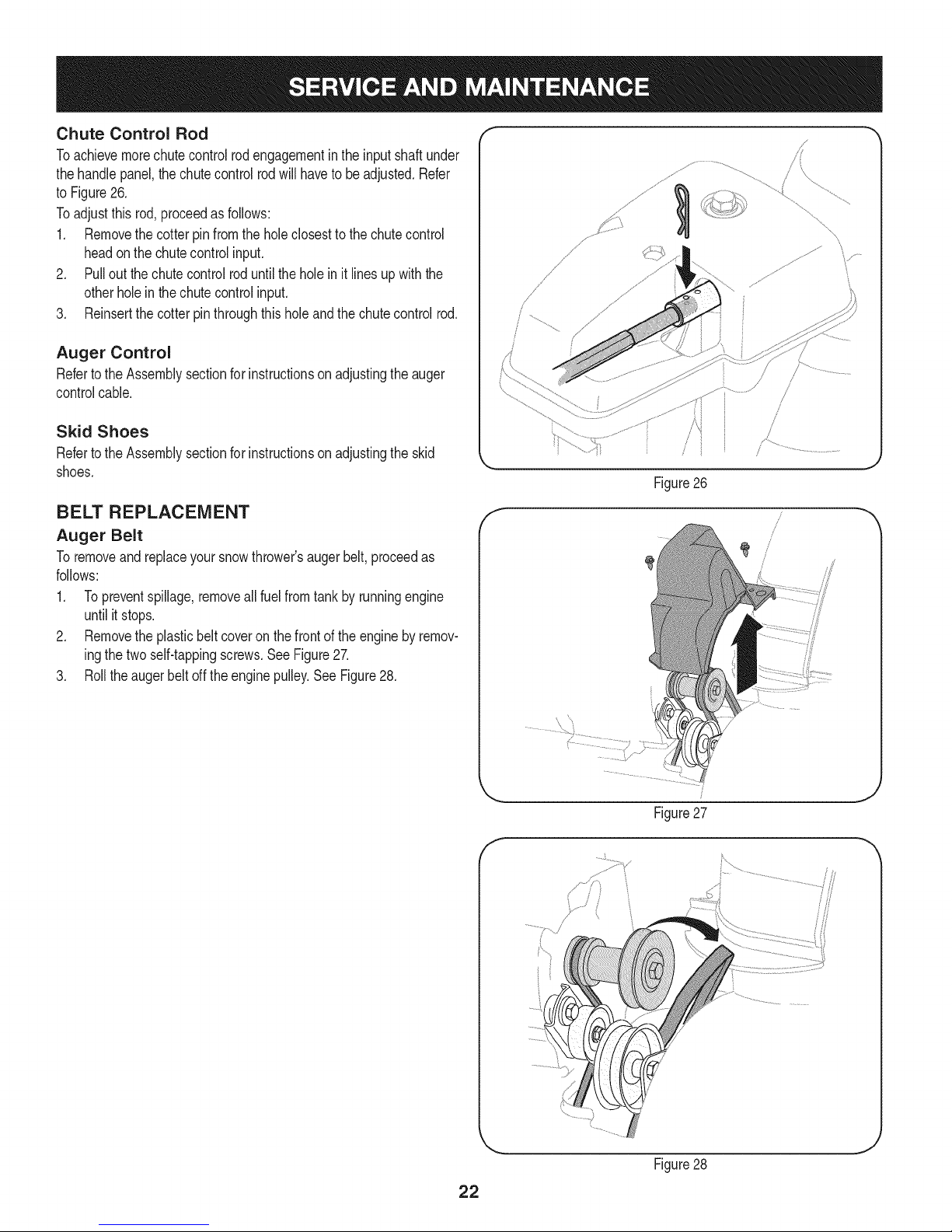
Chute Control Rod
Toachievemorechutecontrolrodengagementinthe inputshaft under
thehandlepanel,thechutecontrolrodwillhavetobeadjusted.Refer
toFigure26.
Toadjustthis rod,proceedasfollows:
1. Removethecotterpinfromthe holeclosesttothechutecontrol
headon the chutecontrolinput.
2. Pullout thechutecontrolroduntiltheholein it linesupwiththe
otherholein thechutecontrolinput.
3. Reinsertthecotterpinthroughthisholeandthechutecontrolrod.
Auger Control
RefertotheAssemblysectionforinstructionsonadjustingtheauger
controlcable.
Skid Shoes
RefertotheAssemblysectionforinstructionsonadjustingthe skid
shoes.
BELT REPLACEMENT
Auger Belt
Toremoveandreplaceyoursnowthrower'saugerbelt,proceedas
follows:
1. Topreventspillage,removeall fuel fromtank by runningengine
untilitstops.
2. Removethe plasticbeltcoveronthefrontoftheenginebyremov-
ingthetwoself-tappingscrews.SeeFigure27.
3. Rolltheaugerbeltoff theenginepulley.See Figure28.
/
/
/
/
/
/
Figure26
f
J
Figure27
f
/
Figure28
22
Page 23
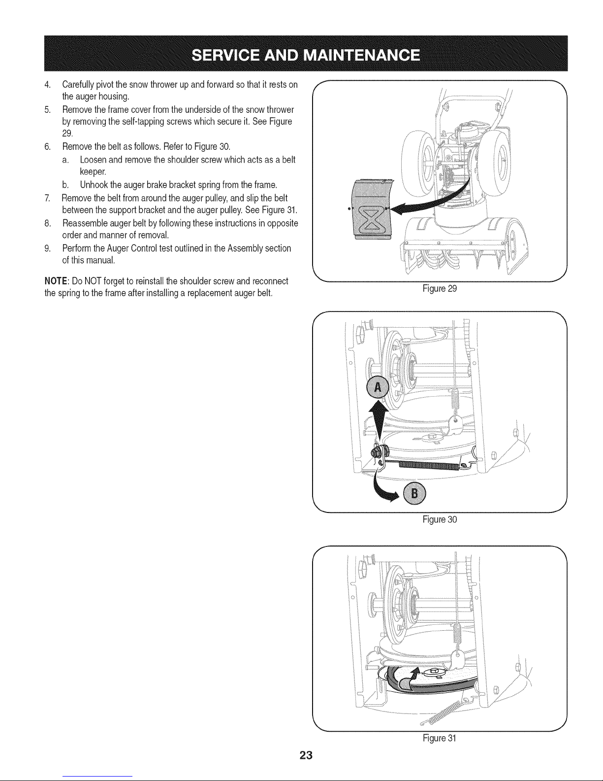
4. Carefullypivotthesnowthrowerupandforwardsothatitrestson
theaugerhousing.
5. Removetheframecoverfromtheundersideofthesnowthrower
byremovingtheself-tappingscrewswhichsecureit.SeeFigure
29.
6. Removethebeltasfollows.RefertoFigure30.
a. Loosenandremovetheshoulderscrewwhichactsasabelt
keeper.
b. Unhooktheaugerbrakebracketspringfromtheframe.
7. Removethebeltfromaroundtheaugerpulley,andslipthebelt
betweenthesupportbracketandtheaugerpulley.SeeFigure31.
8. Reassembleaugerbeltbyfollowingtheseinstructionsinopposite
orderandmannerofremoval.
9. PerformtheAugerControltestoutlinedintheAssemblysection
ofthismanual.
/
NOTE:Do NOTforgetto reinstalltheshoulderscrewandreconnect
thespringtothe frameafterinstallingareplacementaugerbelt.
Figure29
f
Figure30
f
Figure31
23
Page 24
Drive Belt
Toremoveandreplaceyoursnowthrower'sdrivebelt,proceedas
follows:
1. Topreventspillage,removeall fuel fromtank by runningengine
untilitstops.
2. Removethe plasticbeltcoveronthefrontoftheenginebyremov-
ingthetwoself-tappingscrews.SeeFigure27on previouspage.
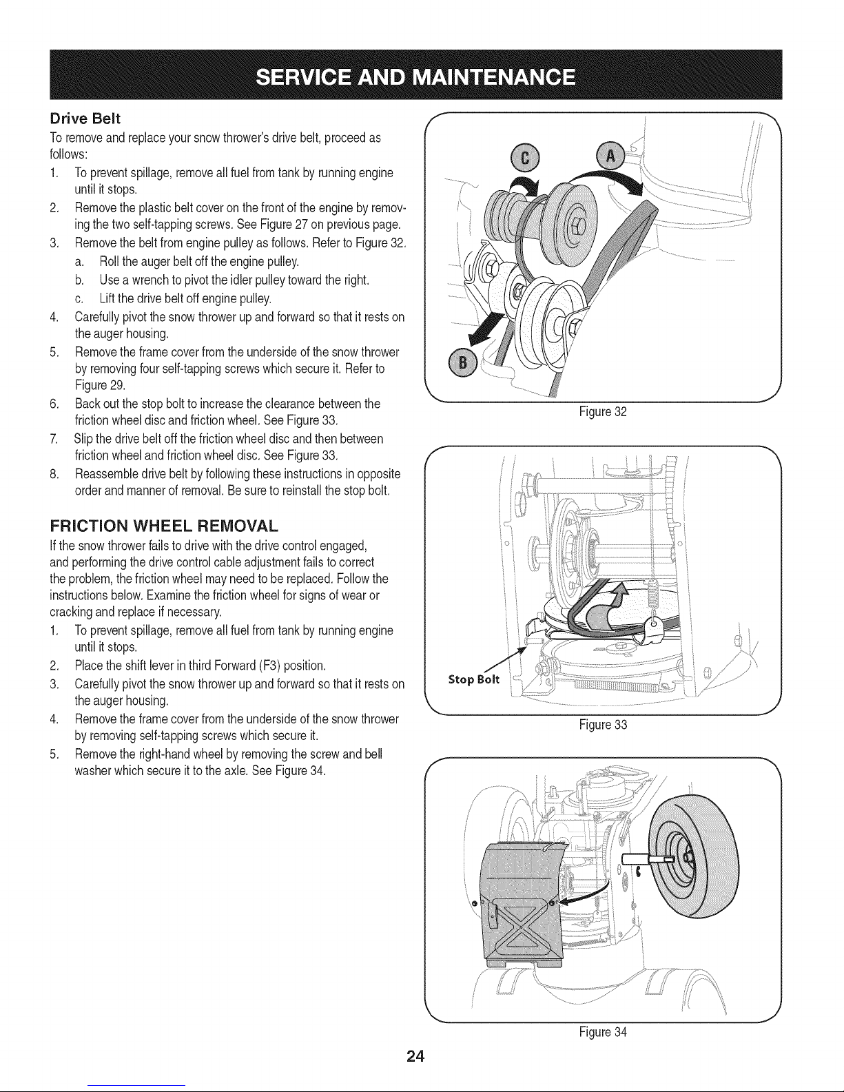
3. Removethe beltfromenginepulleyasfollows.RefertoFigure32.
a. Rolltheaugerbeltoff theenginepulley.
b. Usea wrenchtopivotthe idlerpulleytowardthe right.
c. Liftthedrivebeltoffenginepulley.
4. Carefullypivotthesnowthrowerup andforwardsothat itrestson
theaugerhousing.
5. Removetheframecoverfromtheundersideof thesnowthrower
byremovingfour self-tappingscrewswhichsecureit. Referto
Figure29.
6. Backoutthestopbolttoincreasethe clearancebetweenthe
frictionwheeldiscandfrictionwheel.SeeFigure33.
7. Slipthedrivebeltoffthefrictionwheeldiscandthenbetween
frictionwheelandfrictionwheeldisc.SeeFigure33.
8. Reassembledrivebeltbyfollowingtheseinstructionsin opposite
orderandmannerof removal.Besureto reinstallthe stopbolt.
J
Figure32
f
FRICTION WHEEL REMOVAL
Ifthe snowthrowerfailstodrivewiththedrivecontrolengaged,
andperformingthe drivecontrolcableadjustmentfailstocorrect
theproblem,the frictionwheelmayneedto be replaced.Followthe
instructionsbelow.Examinethefrictionwheelfor signsofwearor
crackingandreplaceifnecessary.
1. Topreventspillage,removeall fuel fromtank by runningengine
untilitstops.
2. Placethe shiftleverin thirdForward(F3)position.
3. Carefullypivotthesnowthrowerupandforwardsothat it restson
theaugerhousing.
4. Removetheframecoverfromtheundersideofthesnowthrower
byremovingself-tappingscrewswhichsecureit.
5. Removethe right-handwheelby removingthescrewandbell
washerwhichsecureitto theaxle.See Figure34.
Stop Bolt
Figure33
f
J
Figure34
24
Page 25

.
Carefullyremovethe hexnut andwasherwhichsecuresthehex
shaftto the snowthrowerframeand lightlytap theshaft'send
todislodgetheballbearingfromtherightsideoftheframe.See
Figure35.
NOTE:Becarefulnottodamagethethreadson theshaft.
7. Carefullypositionthehexshaftdownwardandto theleft before
carefullyslidingthefrictionwheelassemblyoff theshaft.See
Figure36.
NOTE:Ifyou'rereplacingthefrictionwheelassemblyasa whole,
discardthewornpartand slidethenewpartontothehexshaft.
8. Followthestepsaboveinreverseordertoreassemblecompo-
nents.
9. Performthe DriveControlTestoutlinedearlierinthe Serviceand
Maintenancesection.
If you'redisassemblingthefrictionwheeland replacingonlytherubber
ring,proceedasfollows:
1. Removethefourscrewswhichsecurethefrictionwheel'sside
platestogether.SeeFigure37.
2. Removetherubberringfrombetweentheplates.
3. Reassemblethesideplateswitha newrubberring.
Figure35
NOTE: Whenreassemblingthefrictionwheelassembly,makesure
thattherubberringiscenteredand seatedproperlybetweentheside
plates.Tighteneachscrewonlyone rotationbeforeturningthe wheel
clockwiseandproceedingwiththe nextscrew.Repeatthisprocess
severaltimestoensuretheplatesaresecuredwithequalforce
(between6 ft-lbsand 9 ft-lbs).
4. Slidethefrictionwheelassemblybackonto the hexshaftand
reassemblecomponentsbyfollowingtheseinstructionsin
oppositeorderand mannerofremoval.
5. Performthe DriveControlTestoutlinedearlierinthe Serviceand
Maintenancesection.
f -,
Figure36
\
Figure37
25
Page 26

Ifthe snowthrowerwillnotbe usedfor30 daysor longer,orifit istheendofthesnowseasonwhenthelastpossibilityof snowisgone,the
equipmentneedstobestoredproperly.Followstorageinstructionsbelowtoensuretopperformancefromthesnowthrowerfor manymoreyears.
PREPARING ENGINE
Enginesstoredover30daysneedtobedrainedoffueltoprevent
deteriorationandgumfromforminginfuelsystemoronessential
carburetorparts.If thegasolineinyourenginedeterioratesduring
storage,youmayneedto havethecarburetor,andotherfuelsystem
components,servicedor replaced.
1. Removeall fuel fromtank by runningengineuntilit stops.Donot
attempttopourfuelfromthe engine.
2. Changetheengineoil.
3. Removesparkplugandpourapproximately1oz.(30 rnl)ofclean
engineoil intothe cylinder.Pullthe recoilstarterseveraltimesto
distributetheoil,and reinstallthesparkplug.
4. Cleandebrisfromaroundengine,andunder,around,andbehind
muffler.Applya lightfilmof oilon anyareasthatare susceptible
torust.
• Storeina clean,dry andwellventilatedareaawayfromanyap-
pliancethatoperateswithaflameor pilotlight,suchasa furnace,
waterheater,or clothesdryer.Avoidanyareawitha spark
producingelectricmotor,orwherepowertoolsareoperated.
Neverstoresnowthrowerwithfuelintank indoorsor inpoorlyventi-
latedareas,wherefuelfumesmayreachanopenflame,sparkor pilol
lightas ona furnace,waterheater,clothesdryerorgasappliance.
PREPARING SNOW THROWER
Whenstoringthe snowthrowerin anunventilatedormetalstor-
age shed,careshouldbetakentorustprooftheequipment.Using
a light oilor silicone,coattheequipment,especiallyanychains,
springs,bearingsandcables.
• Removealldirt fromexteriorofengineandequipment.
• Followlubricationrecommendations.
• Storeequipmentina clean,dryarea.
• If possible,avoidstorageareaswithhighhumidity.
• Keeptheenginelevelin storage.Tiltingcancausefueloroil
leakage.
26
Page 27

Enginefailsto start
Enginerunningerratically/
inconsistentRPM(huntingor
surging)
Excessivevibration
Lossofpower
Unitfailstopropelitself
Unitfailstodischargesnow
1. ChokecontrolnotinCHOKEposition.
2. Sparkplugwire disconnected.
3. Faultysparkplug.
4. Fueltankemptyor stalefuel.
5. Enginenotprimed.
6. Keynot inserted.
7. Extensioncordnotconnected(when
usingelectricstartbutton,on modelsso
equipped).
1. EnginerunningonCHOKE.
2. Stalefuel.
3. Waterordirt infuel system.
4. Over-governedengine.
1. Loosepartsor damagedauger.
1. Sparkplugwire loose.
2. Gascap ventholeplugged.
1. Drivecableinneedofadjustment.
2. Drivebeltlooseor damaged.
3. Wornfrictionwheel.
1. Chuteassemblyclogged.
2. Foreignobjectlodgedin auger.
3. Augercablein needof adjustment.
4. Augerbeltlooseordamaged.
5. Shearpin(s)sheared.
1. Movechokecontrolto CHOKEposition.
2. Connectwireto sparkplug.
3. Clean,adjustgap,or replace.
4. Filltankwith clean,freshgasoline.
5. PrimeengineasinstructedintheOperationSection.
6. Insertkeyfully intotheswitch.
7. Connectoneendoftheextensioncordto the electric
starteroutletandtheotherendtoa three-prong
120-volt,grounded,ACoutlet.
1. Movechokecontrolto RUNposition.
2. Filltankwith clean,freshgasoline.
3. Drainfueltankby runningengineuntilitstops.Refill
withfreshfuel.
4. ContactyourSearsParts& RepairCenter.
1. Stopengineimmediatelyand disconnectsparkplug
wire.Tightenall boltsand nuts.Ifvibrationcontinues,
haveunit servicedbya SearsParts& RepairCenter.
1. Connectandtightensparkplugwire.
2. Removeiceand snowfromgascap. Becertainvent
holeisclear.
1. Adjustdrivecontrolcable.RefertoServiceand
Maintenancesection.
2. Replacedrive belt.Referto ServiceandMainte-
nancesection.
3. ChangefrictionwheelorcontactyourSearsParts&
RepairCenter.
1. Stopengineimmediatelyand disconnectsparkplug
wire.Cleanchuteassemblyandinsideof auger
housingwithclean-outtoolor a stick.
2. Stopengineimmediatelyand disconnectsparkplug
wire.Removeobjectfromaugerwith clean-outtool
ora stick.
3. Adjustaugercontrolcable.Referto Assembly
section.
4. Replaceaugerbelt.RefertoServiceand Mainte-
nancesection.
5. Replacewith newshearpin(s).
Chutefailstoeasilyrotate180 1. Disassemblechutecontroland reassembleas
1. Chuteassembledincorrectly.
degrees directedintheAssemblysection.
NEED HORE HELP?
Yot,Fttfind. th_ answer a!ld mo_e on ma_age_y_ifeocom _ for free]
Find this and att your other product manua[s ontine.
Get answers from our team of home experts.
Get a personalized maintenance p[an for your home.
Find information and tools to he[p with home projects.
managemylife
b_e'_g_t_/_eyeu by Sea_s
27
Page 28

Craftsman Snow Thrower Model 247.889703
i )
t
_39_
- _' ',_1;f
28
Page 29

Craftsman Snow Thrower IViodel 247.889703
D = 0
931-2643 Clean-OutTool
2. 712-04065 FlangeLockNut
3. 756-04224 FiatidlerPulley
4. 710-0347 HexBolt,3/8-16x 1.75
5. 790-00080A-0637 AugerldlerBracket
6. 736-0174 WaveWasher
7. 938-0281 ShoulderScrew
8. 738-0143 ShoulderScrew
9. 790-00075 BearingHousing
10. 926-04012 PushNut
11. 712-04063 FlangeLockNut,5/16-18
12. 941-0309 BallBearing
13. 732-04460 ExtensionSpring
14. 710-04484 Screw,5/16-18x0.750
15. J731-07525 J ChuteAdapter
16. 710-0703 CarriageScrew,1/4-20x 0.75
17. 731-2635 Clean-outToolMtg.Bracket
18. 684-04264-4044 AugerHousingAssembly,26-inch
19. 712-04064 FlangeLockNut, 1/4-20
20. 918-04172B GearboxAssembly,26-inch
21. 731-06439 SlideShoe
22. 710-0451 CarriageBolt
23. 790-00121-0721 ShavePlate
24. 684-04057A-0637 ImpellerAssembly
25. 917-04126 WormShaft
26. 721-0327 OilSeal
27. 741-0662 FlangeBearing
28. 718-04071 ThrustCollar
D = B
741-0663 FlangeBearing
30. 710-0642 Screw,1/4-20x0.75
31. 790-00087A-0637 BearingHousing
32. 721-0325 Plug
33. 736-3084 FiatWasher
34. 715-04021 DowelPin
35. 684-04108-0637 SpiralAssembly-RH
36. 918-0123A ReducerHsg.-RH
37. 717-04861 WormGear,20T
38. 725-0157 CableTie
39. 738-04124A ShearPin
40. 914-0161 Key
41. 936-0351 FiatWasher
42. 921-0338 OilSeal
43. 741-0661A FlangeBearing
44. 918-0124A ReducerHsg.-LH
45. 711-04284 Axle,Auger,26"
46. 684-04107-0637 SpiralAssembly-LH
47. 714-04040 BowTie CotterPin
48. 731-04870 Spacer
49. 741-0493A FlangeBushing
50. 736-0188 FiatWasher
51. 941-0245 HexFlangeBearing
52. 736-0242 BellWasher
53. 929-0071A ExtensionCord
54. 746-04230A AugerClutchCable
55. 710-0276 Screw,Carriage,5/16-18x 1.00
56. 936-0159 Washer,Fiat,.349x .879x .063
29
Page 30

Craftsman Snow Thrower IViodel 247.889703
_'.'X
'J2_\
=
<
3O
......................................................,_!:...........................¢o_......................
Page 31

Craftsman Snow Thrower Model 247.889703
D = 0 0
684-04112B HandleEngagementAssemblyRH
2. _ 738-04367 _FlangeShoulderScrew
3. 731-04894D LockPlate
4. 684-04250 PivotRod
5. 935-0199A RubberBumper
6. 710-3069 Screw,1/4-20x.500
7. 731-04896B ClutchLockCam
8. 712-04081A ShoulderNut,1/4-20
9. 710-0627 HexScrew,5/16-24x .750
10. 731-06440A LowerChute
11. 720-0274 HandleGrip
12. 710-1233 Screw,#10-24x 0.375
13. 738-04348 ShoulderScrew,1/4-20
14. 710-04586 Screw,1/4-20x 1.625
15. 749-04190A-0637 UpperHandleRH
16. 710-0572 CarriageScrew,5/16-18x2.25
17. 720-04039 ShiftKnob
18. 753-06438 HandlePanel
19. 731-05324 Lens
20. 710-04071 CarriageBolt,5/16-18x 1.0
21. 631-04134B HandleClutchLockRHAssy
22. 914-0101 CotterPin
23. 712-04064 FlangeLockNut,1/4-20
24. 732-0193 CompressionSpring
25. 790-00311A-0637 ShiftLever
26. 790-00248C-0637 PanelBracket
27. 738-04125 ShoulderScrew
28. 684-04311A-0637 ChuteSupportBracket
29. 946-04396A SpeedSelectorCable
30. 736-04446 FiatWasher,.25x .630x .0515
31. 710-0895 Hi-LoScrew,1/4-15x .75
32. 710-04370 HexScrew,1/4-20x 3.00
33. 731-04427A UpperChute
34. _918-04801A J 4-WayChuteGearboxAssembly
35. 710-04187 Hi-LoScrew,1/4-15x 0.5
m = O
984-04338 4-WayChuteControlTM Assembly
37. 749-04191A-0637 UpperHandleLH
38. 710-04326 Screw,#8-16x0.50
39. 732-04219C ClutchLockSpring
40. 712-3087 WingNut,1/4-20
41. 714-04040 BowTie CotterPin
42. 710-0262 CarriageBolt,5/16-18x 1.50
43. 631-04133A HandleClutchLockLHAssy
44. 684-04111B HandleEngagementAssemblyLH
45. 784-5594-0637 CableBracket
46.
720-0284 WingKnob
47. 712-04063 FlangeLockNut,5/16-18
48. 731-06451 ChuteTiltCableGuide
49. 711-04469A ClevisPin
50. 710-04484 Screw,5/16-18x 0.75
51. 749-04138A-0637 LowerHandle
52. 732-04238 TorsionSpring
53. 936-0267 FiatWasher
54. 914-0145 ClickPin
55. 936-0159 FiatWasher,.349x .879x .063
56. 747-05116 ChuteRod
57. 753-06151 HandleAssembly
58. 946-04528A 4-WayCable
946-04477 4-WayCablew/Clip (NotShown)
59. 731-04893A HandlePlunger
60. 710-04879 Screw,Mach.,#8-32x .750
61. 710-04353 Screw,#8x 1.00
62. 731-07031 HandleLever
63. 984-04324A ShiftAssembly
64. 753-06152 GearSetAssembly
65. 753-06153 HandleHousingAssembly
66. 710-1256 Screw,#8-18x 1.250
67. 684-04350 JointBlockAssembly
68. 715-04095 Pin
69. 715-0150 Roll Pin
31
Page 32

Craftsman Snow Thrower Model 247.889703
i,73/
<
32
Page 33

Craftsman Snow Thrower IViodel 247.889703
|= 0 =
656-04055 DiscAssembly,FrictionWheel
2. 684-04153 FrictionWheelAssembly,5.50D
3_ L684-04154B-0637_Supp°rtBracket,Friction Wheel
4. 684-04156A ShiftAssembly,Rod
5. 710-0627 HexScrew,5/16-24,.750,Gr5
6. 710-0788 Screw,1/4-20,1.000
7. 710-1652 Screw,1/4-20x .625
8. 712-04065 Nut,FlangeLock,3/8-16,Nylon
9. 712-0417A Nut,JamLock,5/8-18,Gr5,Nylon
10. 914-0126 Key,HiPro,3/16x 3/4 Dia.
11. 916-0104 E-ring,.500Dia.
12. 716-0136 E-ring,Retaining,.875Dia.
13. 916-0231 E-ring,.750Dia.
14. 917-04209A HexShaft,.8125,7-Tooth
15. 917-04230 Gear,80-Tooth
16. 726-0221 SpeedNut,.500
17. 932-0264 ExtensionSpring
18. 736-0242 Washer,Bell, .340x .872x .060
19. .936-0287 LWasher,Flat,.793x 1.24x .060
20. 736-04161 Washer,Flat,.75x 1.00x.060
21. 748-04112B Spacer,Shldr.,.3175IDx .500x .094
22. 735-04100 Plug,1/2ID
23. 738-04184A Screw,Shoulder,.37 x .105,1/4-20
24. 738-0924A Screw,1/4-28,.375
25. 941-0245 Bearing,HexFlangex .75ID
26. 941-0563 Bearing,Ball,17x40x 12
27. ,746-04229B _ClutchCable,Wheel,44.95"
28. 790-00289A-0637 Plate,Cover
29. 748-0190 Spacer,.508IDx .75ODx .68
30. 756-0625 Roller,Cable
31. 790-00096-0637 FrontGuideBracket,AugerCable
32. 790-00180A-4044 Frame
33. 790-00206A-0637 GuideBracket,AugerCable
34. 790-00207B GuideBracket,DriveCable
35. 790-00316-0637 Cover,Frame
36. 634-04148A-0911 WheelAssembly-RH
634-04147A-0911 WheelAssembly- LH
37. 731-04873 Spacer,1.25x .75x 3.0
38. 938-04168 Axle,.75x 22"
D = O O
735-04099 Plug,3/8 ID
40. 710-0809 HexScrew,1/4-20,1.25,Gr5
41. 710-0191 HexScrew,3/8-24,1.25,Gr8
42. 710-0672 HexScrew,5/16-24,1.25,Gr5
43. 710-0654A Screw,Seres,3/8-16,1.00
44. 710-1245B HexScrew,5/16-24,.875,Gr8
45. 712-04064 Nut, FlangeLock,1/4-20,Nylon
46. 926-04012 Nut, Push-on,.25Dia.
47. 731-05353 Cover,Belt
48. 732-04308B Spring,Torsion,.850 IDx .354
49. 736-0247 Washer,Flat,.406x 1.25x .157
50. 936-0119 Washer,Lock.3125
51. 736-0505 Washer,Flat,.34x 1.50x .150
52. 748-04053A Pulley,Adapter,.75Dia.
53. 736-0329 LockWasher
54. 750-04303 Spacer,.875IDx 1.185OD
55. 750-04477A Spacer,.340x .750x .360
56. 954-04050 Belt,AugerDrive
57. 954-04260 Belt,WheelDrive
58. 756-04109
59. 756-04113
60. 756-04252
61. 790-00208C
62. 684-04169
63. 750-04571
64. 935-04054
65. 710-0751
66. 732-04311A
67. 712-04063
68. 936-3015
69. 790-00217A-0637
70. 790-00218A-0637
71. 936-0264
72. 732-0705
73. 710-04022
Pulley,AugerDrive,8.1x .5
Pulley,Half,Vx 2.600OD
Pulley,Half,3/8-Vx 1.7160OD
IdlerBracket,WheelDrive
IdlerPulleyAssembly
Spacer,Shoulder,.26x .79x .538
Rubber,FrictionWheel,5.50D
HexScrew,1/4-20,.620,Gr5
Spring,Torsion,.750IDx .968
Nut,FlangeLock,5/16-18,Nylon
Washer,Flat,.469x .875x .105
PivotBracket,SpeedSelector
ShiftBracket,SpeedSelector
Washer,Fiat,.330x .630x .0635
CableControlWire
Screw,M8-1.25
74. 738-04439 ShoulderScrew
75. 710-0599 Screw,AB,1/4-20x .500
76. 752Z270-SU ReplacementEngine
33
Page 34

Craftsman Engine IViodel 270=SU=11 For Snow IViodel 247.889703
24
23- ,_
21
25
_2s
m
19
20
20
21
22
23
24
25
26
951-11282
710-04911
951-10657
951-11285
712-04214
951-11111
710-04914
710-04915
951-10642A
m = O O
MufflerAssembly
StudM8x36
MufflerStudAssembly
ExhaustPipeGasket
Nut,M8
ExhaustPipeShield
BoltM6xl0
BoltM6x12
MufflerShield
34
Page 35

Craftsman Engine Model 270=SU=11 For Snow Model 247.889703
43 _44
J
38 39
m
34
35
36
37
38
39
4O
42
43
44
45
951-11897
951-11112
951-10634
712-04213
951-11284
951-10757
951-10637
731-05632
951-10640
951-10635
710-04919
37
D = O Q
CarburetorGasketPlate
ChokeControl
EngineShroud
Nut
ChokeKnob
ThrottleControlKnob
IgnitionSwitchAssembly
Key
Choke PushRod
HeaterBox
BoltM6x25
35
Page 36

Craftsman Engine IViodel 270=SU=11 For Snow IViodel 247.889703
71
77
36
Page 37

Craftsman Engine IViodel 270=SU=11 For Snow IViodel 247.889703
m
52
53
54
55
56
57
58
59
6O
61
62
63
64
65
66
67
68
69
7O
71
72
951-12111
951-11632
951-12007
951-11633
710-04915
951-11113
951-11573
951-11356
736-04461
951-11902
714-04074
951-11575
951-11369
951-10307
951-11247A
951-11576
715-04092
715-04089
951-11371
951-12125
710-04932
D = O O
PistonRingSet
PistonPinSnapRing
Piston
PistonPin
BoltM6x12
Air Shield
ConnectingRodAssembly
GovernorArm Shaft
Washer5.2xl.9
GovernorSeal
CotterPin
CamshaftAssy.
RadialBallBearing,6205
WoodruffKey
CrankshaftKit
(Incl.66-65,76,81)
GovernorGear/ShaftAssembly
DowelPin7x14
DowelPin9x14
CrankcaseCoverGasket
CoverComp,Crankcase
BoltM8x32
m
73
75
76
77
78
79
8O
81
951-11283
951-11577
951-11368
951-11249
951-11350
736-04440
710-04906
951-11370
133
951-10641
952Z270-SU-11
951-11246
951-10661B
951-11059A
951-11060A
Oil FillPlugAssembly
O-Ring15.8x2.5
OilSeal,25x41.25x6
CrankcaseKit
(Incl.61,64,76,77,81)
Oil DrainPipeAssy.
Washer10x16x1.5
Oil DrainPlug
OilSeal25x41.25x6
Oil DrainAssembly
CompleteEngine
CrankcaseCoverKit
(Incl.64,70-73,76)
GasketKit- External
(Incl.4,21,29-31,34,79)
GasketKit- Complete
(Inc1.4,21,29-31,34,46,60,
61,70,76,79,82)
ShortBlock
(Incl.4,21,29,30,46,48,49,
52-55,58-72,74-81)
37
Page 38

Craftsman Engine IViodel 270=SU-11 For Snow IViodel 247.889703
18
13
12 I_ 14
5O
46
134
17
2
38
Page 39

Craftsman Engine IViodel 270=SU=11 For Snow IViodel 247.889703
m
1
2
3
3a
4
5
6
7
8
9
10
11
12
13
14
15
16
17
18
46
47
48
49
5O
51
134
710-04744
951-11054A
731-07059
726-04101
951-11565
951-12000
951-11892
751-11124
751-11123
951-11893
710-04902
951-12002
951-12003
951-12004
951-11894
710-04933
951-11895
951-10668A
951-10292
951-11572
951-10648
951-11899
715-04090
951-10647A
951-10647A
951-11063A
952Z270-SU-11
951-10661B
951-11059A
D = W O
BoltM6x16
ValveCover
BreatherHose
HoseClamp
ValveCoverGasket
Retainer,In.ValveSpring
RockerArmAssembly
Nut,PivotLocking
AdjustingNut,Valve
RockerArm
Bolt,Pivot
Adjuster,ExhValve
Retainer,Ex.ValveSpring
ValveSpring
IntakeValveSeal
BoltM8x55
PushRodGuide
CylinderHeadAssembly
(Incl.4,5,7-14,16,17,21,
29,30,46,50,51)
SparkPlug/F6Rtc
Gasket,CylinderHead
PushRod Kit
Tappet
DowelPin 10x16
ValveKit
ValveKit
ValveCoverKit
CompleteEngine
GasketKit- External
(Incl.4,21,29-31,34,79)
GasketKit- Complete
(Incl.4,21,29-31,34,46,60,
61,70,76,79,82)
39
Page 40

Craftsman Engine IViodel 270=SU=11 For Snow IViodel 247.889703
31
32
33_
4O
Page 41

Craftsman Engine IViodel 270=SU=11 For Snow IViodel 247.889703
m
27
28
29
30
31
32
32
33
34
a
b
C
d
e
f
g
h
I
J
k
I
m
n
o
P
q
r
s
t
U
V
W
X
Y
710-04939
710-04910
951-11567
951-11896
951-11569A
951-10639A
951-11824
951-10638A
951-11897
n/a
n/a
n/a
n/a
n/a
n/a
n/a
n/a
n/a
n/a
951-11699
951-11906
n/a
n/a
n/a
n/a
n/a
n/a
n/a
951-11589
n/a
951-11348
710-04945
951-11349
710-04938
951-11021A
D = O O
StudM6x117
StudM6x105
CarburetorInsulatorGasket
CarburetorInsulator
CarburetorGasket
PrimerAssembly
PrimerBulb
CarburetorAssembly
CarburetorGasketPlate
ChokeShaft
ChokePlate
ThrottleShaft
ThrottlePlate
ScrewM3x5
LockWasher
Gasket,ThrottlePlate
IdleJet Assembly
IdleSpeedAdjustingScrew
MixtureScrew
PrimerHose
HoseClamp
CarburetorBody
FloatPin
EmulsionTube
NeedleValve
MainJet
NeedleValveSpring
Float
FuelBowlGasket
FuelBowl
FuelBowlGasket
FuelBowlMountingBolt
FuelDrainPlugGasket
FuelDrainPlug
CarburetorKit- Major
(Incl.g,h,l,n,o,p,q,r,s,t,y,x)
41
Page 42

Craftsman Engine IViodel 270-SU-11 For Snow IViodel 247.889703.
84
_1 _130
82
89
31
#
94_ 135
96
m
82
83
84
85
87
88
89
90
91
93
94
95
96
87
130
131
135
88
951-10646
951-11110
710-04940
710-04919
951-12416
951-10909
951-10911
712-04209
710-04915
951-10663A
736-04455
710-04974
951-10658
710-04979
951-11109
731-05696
;o
95
_'91 91 94.4 _95
D = O O
IgnitionCoilAssembly
Air FlowShield
BoltM6xlO
BoltM6x25
Flywheel
Fan,Cooling
Pulley,Starter
Nut,Special,M14x1.5
BoltM6x12
BlowerHousing
Gasket6
BoltM6xlO
RecoilStarter
BoltM6x18
BlowerHousingShield
RecoilStarterHandle
42
Page 43

Craftsman Engine IViodel 270=SU=11 For Snow IViodel 247.889703.
m
97
98
99
100
101
102
104
105
106
107
108
109
951-10758
710-04928
951-11108
951-11935
951-10664
951-10665
951-11106
712-04212
710-04908
951-11700
951-10650
710-04915
97
D = O 0
ThrottleControlAssemlby
BoltM6x12
GovernorSystemShield
GovernorSpring
ThrottleLinkageSpring
ThrottleLinkage
GovernorArm
NutM6
GovernorArmBolt
FuelHoseClamp
FuelLineKit
BoltM6x12
m
110
111
112
114
115
116
117
118
119
120
132
951-10662
710-04905
710-04915
951-11381
951-11913
951-11904
951-12482
951-10649A
951-11933
951-10653A
951-10651
D = O @
Engine/ DipstickCover
Bolt
BoltM6x12
Oil FillTubeO-Ring
Oil FillTubeAssembly
Dipstick O-Ring
DipstickAssembly
FuelCapAssembly
FuelLevelIndicator
FuelTankAssembly
FuelTankFilter/Nipple
43
Page 44

Craftsman Engine Model 270=SU=11 For Snow Model 247.889703.
777122991
777122990
777S33610
i ,
777123026
777122992
44
Page 45

Craftsman Snow Thrower IViodel 247.889703
777S32636
1001 lno-Nv:=lo
7VflNV_ S,HOIVU3dO QV3U 7;
N3HMNOIlflV9 V91X3 389 "$830NV18t8 IV ]98VHOSIO
103810 H]A]H '$31UflrNI $133r80 NMOUH1 QIOAV01 "t'
]H0_38 O3dd01S 3AVH $1HVd ONIAO_ ]lV lllNfl S]3QNVH
ONIH38NIV_3U ONV '3NIgN] d018 '$U]A31 HOlfllO 39VgN]$10 "8
"]lflH3 39UVHOSIO 9013Nfl Ol ]OOl lflO'NV3]3 ]Sfl "Z
"133JONV SQNVH31V1fldWV NV3 _39flV UO_3]]3dWI NIIM
IOVlNOO "EI39nvONV g31"i3dl_Jl9NILVIOEI I_OEI:IkVMV d33)1"L
"S]OVJHflS 1]AVH9 NO 9NIIVH3dO
'3NIHOVVJ 9NI31^EG8 EIO 9NI99013Nn
777S32236
777D16339
777122339
777D16338
STARTING INSTRUCTIONS:
777D16341
777122363
AUGER CONTROL I_
777122435
777D16340
777X43688
/ USEE85ORFuEL
/ CONTAININGMORE
THAN 10% ETHANOL
DRIVE CONTROL
777D16357
45
Page 46

MTD CONSUMER GROUP INC (MTD), the California Air Resources Board (CARB)
and the United States Environment Protection Agency (U. S. EPA)
Emission Control System Warranty Statement
(Owner's Defect Warranty Rights and Obligations)
EMISSIONCONTROLSYSTEMCOVERAGEISAPPLICABLETOCERTIFIEDENGINESPURCHASEDINCALIFORNIAIN2005ANDTHERE-
AFTER,WHICHAREUSEDINCALIFORNIA,ANDTOCERTIFIEDMODELYEAR2005ANDLATERENGINESWHICHAREPURCHASEDAND
USEDELSEWHEREINTHEUNITEDSTATES.
CaliforniaandelsewhereintheUnitedStatesEmissionControlDefectsWarrantyCoverage
TheCaliforniaAir ResourcesBoard(CARB),U.S. EPAandMTDarepleasedtoexplaintheemissionscontrolsystemwarrantyonyourmodelyear
2006andlatersmalloff-roadengine.InCalifornia,newsmalloff-roadenginesmustbe designed,builtand equippedtomeettheStatesanti-smog
standards.ElsewhereintheUnitedStates,newnon-road,spark-ignitionenginescertifiedformodel2005and later,mustmeetsimilarstandardsset
forthbythe U.S.EPA.MTDmustwarrantytheemissioncontrolsystemonyourenginefor theperiodoftimelistedbelow,providedtherehasbeen
noabuse,neglector impropermaintenanceofyoursmalloff-roadengine.
Youremissioncontrolsystemmayincludepartssuchasthecarburetor,fuel-injectionsystem,theignitionsystem,andcatalyticconverter,fueltanks,
fuellines,fuelcaps,valves,canisters,filters,vaporhoses,clamps,connectors,andotherassociatedemission-relatedcomponents.
Whereawarrantableconditionexists,MTDwill repairyoursmalloff-roadengineat nocost to yourincludingdiagnosis,partsandlabor.
MANUFACTURER'S WARRANTY COVERAGE:
Thisemissionscontrolsystemiswarrantedfor twoyears.If anyemission-relatedpart onyourengineisdefective,thepartwill berepairedor
replacedbyMTD.
OWNER'S WARRANTY RESPONSIBILITIES:
Asthesmalloff-roadengineowner,youare responsibleforthe performanceofthe requiredmaintenancelistedinyourOwner'sManual.MTD
recommendsthatyouretainall yourreceiptscoveringmaintenanceson yoursmalloff-roadengine,butMTDcannot denywarrantysolelyforthe
lackofreceiptsor foryourfailureto ensuretheperformanceto allscheduledmaintenance.
Asthesmalloff-roadengineowner,youshouldhoweverbeawarethat MTDmaydenyyourwarrantycoverageifyoursmalloff-roadengineorpart
hasfaileddue toabuse,neglect,impropermaintenanceor unapprovedmodifications.
Youare responsiblefor presentingyoursmalloff-roadenginetoan AuthorizedMTDServiceDealerassoonasa problemexists.Thewarranted
repairsshouldbe completedina reasonableamountof time,notto exceed30 days.
Ifyouhaveanyquestionsregardingyourwarrantyrightsand responsibilities,youshouldcontacta MTDServiceRepresentativeat 1-800-800-7310
andaddressisMTDCONSUMERGROUP,RO.Box361131,ClevelandOH,44136-0019.
DEFECTS WARRANTY REQUIREMENTS FOR 1995 AND LATER SMALL OFF-ROAD ENGINES:
Thissectionappliesto 1995andlatersmalloff-roadengines.The warrantyperiodbeginsonthedatetheengineor equipmentis deliveredtoan
ultimatepurchaser.
(a) GeneralEmissionsWarrantyCoverage
MTDmustwarranttothe ultimatepurchaserandeachsubsequentpurchaserthattheengineis:
(1)Designed,built,andequippedsoas to conformwithallapplicableregulationsadoptedbythe AirResourcesBoardpursuantto itsauthorityin
Chapters1and2,Part5, Division26of theHealthandSafetyCode;and
(2) Freefromdefectsin materialsandworkmanshipthatcausethe failureofa warrantedpartto beidenticalin all materialrespectstothe partas
describedin theenginemanufacturer'sapplicationforcertificationfora periodoftwoyears.
(b)Thewarrantyonemissions-relatedpartswillbe interpretedas follows:
(1)Anywarrantedpart thatisnotscheduledforreplacementas requiredmaintenanceinthe writteninstructionsrequiredbySubsection(c)
mustbewarrantedfor the warrantyperioddefinedinSubsection(a)(2).Ifanysuchpartfailsduringtheperiodof warrantycoverage,it mustbe
repairedor replacedbyMTDaccordingto Subsection(4)below.Anysuchpartrepairedor replacedunderthewarrantymustbewarrantedfor
theremainingwarrantyperiod.
(2)Anywarrantedpartthat is scheduledonlyfor regularinspectioninthe writteninstructionsrequiredbySubsection(c)mustbewarrantedfor
thewarrantyperioddefinedinSubsection(a)(2).A statementinsuchwritteninstructionstotheeffectof"repairor replaceasnecessary"will
notreducetheperiodof warrantycoverage.Anysuchpartrepairedorreplacedunderwarrantymustbe warrantedfortheremainingwarranty
period.
(3) Anywarrantedpartthat whichis scheduledfor replacementas requiredmaintenancein the writteninstructionsrequiredby Subsection(c)
mustbewarrantedfor the periodoftimepriortothefirstscheduledreplacementpointforthat part.Ifthepartfailspriorto thefirstscheduled
replacement,thepartmustbe repairedor replacedbyMTDaccordingtoSubsection(4) below.Anysuchpart repairedor replacedunder
warrantymustbewarrantedfor theremainderof theperiodpriorto the firstscheduledreplacementpointforthepart.
Page 47

(4)Repairorreplacementofanywarrantedpartunderthewarrantyprovisionsofthisarticlemustbeperformedatnochargetotheownerata
warrantystation.
(5)NotwithstandingtheprovisionsofSubsection(4)above,warrantyservicesorrepairsmustbeprovidedatallMTDdistributioncentersthat
arefranchisedtoservicethesubjectengines.
(6)Theownermustnotbechargedfordiagnosticlaborthatleadstothedeterminationthatawarrantedpartisinfactdefective,providedthat
suchdiagnosticworkisperformedatawarrantystation.
(7)Theenginemanufacturerisliablefordamagestootherenginecomponentsproximatelycausedbyafailureunderwarrantyofanywarranted
part.
(8)Throughouttheengine'swarrantyperioddefinedinSubsection(a)(2),MTDwillmaintainasupplyofwarrantedpartssufficienttomeetthe
expecteddemandforsuchparts.
(9)Anyreplacementpartmaybeusedintheperformanceofanywarrantymaintenanceorrepairsandmustbeprovidedwithoutchargetothe
owner.SuchusewillnotreducethewarrantyobligationsofMTD.
(10)Add-onormodifiedpartsthatarenotexemptedbytheAirResourcesBoardmaynotbeused.Theuseofanynon-exemptedadd-onor
modifiedpartsshallbegroundsfordisallowingawarrantyclaimmadeinaccordancewiththisarticle.Theenginemanufacturershallnotbe
liableunderthisarticletowarrantfailuresofwarrantedpartscausedbytheuseofnon-exemptedadd-onormodifiedpart.
(c)MTDwill includeacopyof the followingemissionwarrantypartslistwitheachnewengine,usingthoseportionsofthe listapplicabletothe
e__&gine.
(1)FuelMeteringSystem
•Coldstartenrichmentsystem(softchoke)
,,Carburetorandinternalparts
•Fuel Pump
•FuelTank
(2)Air InductionSystem
•Aircleaner
•Intakemanifold
(3) IgnitionSystem
•Sparkplug(s)
•MagnetoIgnitionSystem
(4)ExhaustSystem
Catalyticconverter
•SAI (Reedvalve)
(5) MiscellaneousItemsUsedin AboveSystem
Vacuum,temperature,position,timesensitivevalvesand switches
Connectorsandassemblies
(6) Evaporativecontrol
•Fuel HosecertifiedforARBevaporativeemissionof2006.
•Fuel HoseClamps
Tetheredfuelcap
Carboncanister
Vaporlines
GD0C-100174Rev.B
Page 48

Look For Relevant Emissions Durability Period and
Air index information On Your Engine Emissions Label
Engines that are certified to meet the California Air Resources Board (CARB) Tier 2 Emission Standards must
display information regarding the Emissions Durability Period and the Air Index. Sears Brands Management
Corporation makes this information available to the consumer on our emission labels.
The Emissions Durability Period describes the number of hours of actual running time for which the engine is
certified to be emissions compliant, assuming proper maintenance inaccordance with the Operating & Mainte-
nance Instructions. The following categories are used:
Moderate: Engine is certified to be emission compliant for 125 hours of actual engine running time.
Intermediate: Engine is certified to be emission compliant for 250 hours of actual engine running time.
Extended: Engine is certified to be emission compliant for 500 hours of actual engine running time.
For example, a typical walk-behind lawn mower is used 20 to 25 hours per year. Therefore, the Emissions
Durability Period of an engine with an intermediate rating would equate to 10 to 12 years.
The Air index is a calculated number describing the relative level of emissions for a specific engine family. The
lower the Air Index, the cleaner the engine. This information is displayed in graphical form on the emissions label.
After July 1,2000, Look For Emissions Compliance Period
On Engine Emissions Compliance Label
After July 1, 2000 certain Sears Brands Management Corporation engines will be certified to meet the United
States Environmental Protection Agency (USEPA) Phase 2 emission standards. For Phase 2 certified engines, the
Emissions Compliance Period referred to on the Emissions Compliance label indicates the number of operating
hours for which the engine has been shown to meet Federal emission requirements.
For engines less than 225 cc displacement, Category C = 125 hours, B = 250 hours and A = 500 hours.
For engines of 225 cc or more, Category C = 250 hours, B = 500 hours and A = 1000 hours.
This isa generic representation of the emission label typically found on a certified engine.
FAMILYYBSXS.3192VA 274812
GDOC-100182Rev.B
48
Page 49

Congratulations on making a smart purchase. Your new Craftsman® product is designed and
manufactured for years of dependable operation. But like all products, it may require repair
from time to time. That's when having a Repair Protection Agreement can save you money and
aggravation.
Here's what the Repair Protection Agreement* includes:
[] Expert service by our 10,000 professional repair specialists
[] Unlimited service and no charge for parts and labor on all covered repairs
[] Product replacement up to $1500 if your covered product can't be fixed
[] Discount of 25% from regular price of service and related installed parts not covered by the
agreement; also, 25% off regular price of preventive maintenance check
[] Fast help by phone - we call it Rapid Resolution - phone support from a Sears representative.
Think of us as a "talking owner's manual."
Once you purchase the Repair Protection Agreement, a simple phone call is all that it takes for you
to schedule service. You can call anytime day or night, or schedule a service appointment online.
The Repair Protection Agreement is a risk-free purchase. If you cancel for any reason during the
product warranty period, we will provide a full refund. Or, a prorated refund anytime after the
product warranty period expires. Purchase your Repair Protection Agreement today!
Some limitations and exclusions apply. For prices and additional information in the U.S.A.
call 1=800=827=6655.
*Coverage in Canada varies on some items. For full details call Sears Canada at 1=800=361=
6665.
Sears Installation Service
For Sears professional installation of home appliances, garage door openers, water heaters, and
other major home items, in the U.S.A. or Canada call 1=800=4=MY=HOME®.
49
Page 50

Declaraci6n de garantia ............................ Pagina 50
Practicas operaci6n seguras ..................... Pagina 51
Montaje ...................................................... Pagina 55
Operaci6n .................................................. Pagina 61
Servicio y Mantenimiento .......................... Pagina 65
Soluci6n de problemas .............................. Pagina 74
Acuerdo de protecci6n para reparaciones .... Pagina 79
Lista de piezas ........................................... Pagina 28
NOmero de servicio ................................... Cubierta
posterior
Almacenamiento fuera de temporada ....... Pagina 73
GARANTiA COMPLETA CRAFTSMAN POR DOS AltOS
PORDOSANOSapartir dela fechade lacornpra,esteproductoest,.garantizadopordefectosenlosrnaterialesyla rnanodeobra.
Losproductosdefectuososser_.nreparadossincostoo reernplazadossincostosi lareparaci6nnoest,.disponiNe.
La presentegarantiaseanulasiseutilizaesteproductoalgunavezparaprestarservicioscornercialeso siseIoalquilaa otrapersona.
Paraobtener informaci6nsobre elalcancede la garantiay solieitar la reparaci6no el reemplazo,visite elsitio Web:www.craftsman.com
Esta garantia cubre0NICAMENTElosdefectos en los rnaterialesy enla rnanode obra. Estagarantia NOcubre:
• Elernentosno renovablesquepuedendesgastarsepor eluso normal,duranteel plazodela garantia,incluyendoentreotros,lasbarrenas,
laspaletasdelas barrenas,loscortadoresde desplazarniento,laszapatasantideslizantes,la placade raspado,lospasadoresdecuchilla,
la bujia,elfiltrode aire,lascorreasyel filtrodeaceite.
• Serviciosdernantenirnientoest_.ndar,carnbiosdeaceiteo afinaci6n.
• Carnbiode neurn_.ticoso reparacionesporpinchadurasconobjetosexternoscornoclavos,espinas,toconesovidrios.
• Reernplazoo reparaci6nde neurn_.ticoso ruedascornoresultadodel desgastenormal,unaccident&o funcionarniento
o rnantenirnientoincorrectos.
• Reparacionesrequeridascornoresultadodel usoinadecuadopot partedeloperador,incluyendoentreotrosel da_oocasionadoporobjetos
queirnpactanla rn_.quinay quetuercenel bastidor,el ejede labarrena,etc.,odebidoa queel motorrueaceleradoenexceso.
• Reparacionesnecesariasdebidoa negligenciadeloperador,incluyendoentre otros,da_osrnec_.nicoyel_ctricoocasionadopor
unalrnacenarnientonoapropiado,fallaporel uso deaceitede gradoy/o cantidadnoapropiadoso fallapornodar rnantenirniento
alequipodeacuerdoconlas instruccionescontenidasenel manualdel operador.
• Lirnpiezao reparacionesdel motor(sisternade combustible)debidasa combustiblequese deterrninaest,.contarninadou oxidado(viejo).
Engeneral,elcombustibledebeutilizarseenunperiodono mayorde30diasa partirde suadquisici6n.
• Eldeterioroydesgastenormalde losacabadosexteriores,oreernplazode laetiquetadelproducto.
Estagarantialeotorgaderechoslegalesespecificos,peroustedpodriagozardeotrosderechosen raz6ndesulugarde residencia.
Sears Brands Management Corporation, Hoffman Estates, IL 60179
Tipodeaceitedelmotor:
Capacidadde aceitedel motor:
Capacidadde combustible:
Bujias:
Separaci6ndelasbujias:
©KCDIP,LLC
5W-30
20 onzas
2.3 cuartos
F6RTC
.020" a .030"
N_mero de rnodelo ..........................................................
N_mero de sede ..............................................................
Feehadeeompra.............................................................
RegistrearribaelnOrnerodel rnodelo,el nOrnerode serieyla fecha
de cornpra
50
Page 51

Lapresenciadeeste sfrnboloindicaquesetratade instrucciones
irnportantesde seguridadquese debenrespetarparaevitar
ponerenpeligrosu seguridadpersonaly/o materialy lade otras
personas.Leay siga todaslasinstruccionesdeestemanualantes
de poneren funcionarnientoestarn_.quina.Si no respetaestas
instruccionespodrfaprovocarlesionespersonales.Cuandoveaeste
sfrnbolo,ipresteatenci6nala advertencia!
Estarn_.quinarueconstruidaparaseroperadadeacuerdocon
lasreglasdeseguridadcontenidasenestemanual.AIigualque
concualquiertipodeequipornotorizado,undescuidoo errorpor
partedeloperadorpuedeproducirlesionesgraves.Estarn_.quina
escapazde arnputarrnanosy piesy dearrojarobjetoscongran
fuerza.Deno respetarlas instruccionesde seguridadsiguientesse
puedenproducirlesionesgraveso larnuerte.
PROPOSICION 65 DE CALIFORNIA
Elescapedel motordeesteproducto,algunosde suscornponentes
y algunoscornponentesdelvehfculocontieneno liberansustancias
qufrnicasqueelestadodeCaliforniaconsideraquepuedenproducir
c_.ncer,defectosde nacirnientouotrosproblernasreproductivos.
CAPACITACI6N
• Lea,entiendaycurnplatodaslas instruccionesincluidasen
la rn_.quinayen losrnanualesantesdernontarlay utiNzarla.
Guardeestemanualenun lugarseguroparaconsultasfuturasy
peri6dicas,asf cornoparasolicitarrepuestos.
• Leael ManualdelOperadorysigatodaslasadvertenciase
instruccionesdeseguridad.Elfracasode hacerasf puedecausar
la heridaseriaal operadory/o personaspresentes.
• Farniliarfcesecontodosloscontrolesycon el usoadecuado
delosrnisrnos.Sepac6rnodetenerlarn_.quinaydesactivarlos
controlesr_.pidarnente.
• Noperrnitanuncaque losni_osrnenoresde14a_osutilicen
estarn_.quina.Losni_osde 14a_osen adelantedebenleery
entenderlasinstruccionesdeoperaci6ny norrnasdeseguridad
contenidaseneste manual,yen la rn_.quinaydebenserentrena-
dosy supervisadosporun adulto.
• Nuncaperrnitaquelos adultosoperenestarn_.quinasinrecibir
antesla instrucci6napropiada.
• Losobjetosarrojadosporla rn_.quinapuedenproducirlesiones
graves.Planifiqueel patr6nenel quevaair arrojandonievepara
evitarque ladescargade materialse realicehacialos carninos,
losobservadores,etc.
• Mantengaa losobservadores,ayudantes,rnascotasy ni_ospor
Iornenosa75piesde la rn_.quinarnientrasla rnisrnaest,.en
funcionarniento.Detengalarn_.quinasi alguienseacerca.
• Seaprecavidoparaevitarpatinarseo caerseespecialrnente
cuandooperala rn_.quinaen reversa.
Su responsabilidad--Restrinja el usode estarn_.quina
rnotorizadaa las personasque lean,cornprendany respetenlas
advertenciase instruccionesqueaparecenenestemanualyen la
rn_.quina.
iGUARDEESTASINSTRUCCIONES!
PR E PARATIVO S
Inspeccionerninuciosarnenteel_.readondeutilizar_,elequipo.Saque
todoslosfelpudos,peri6dicos,trineos,tablas,cablesy otrosobjetos
extra_osconlosquepodrfatropezaroquepodrfanserarrojadospor
labarrena/irnpulsor.
• Paraprotegerselosojosutilicesiernpreanteojosoantiparras
de seguridadrnientrasoperala rn_.quinao rnientrasla ajusta
o repara.Losobjetosarrojadosquerebotanpuedenproducir
lesionesocularesgraves.
• Nooperelarn_.quinasinla vestirnentaadecuadaparaestaral
airelibreen invierno.Noutilicealhajas,bufandaslargasu otras
prendassueltasquepodrfanenredarseenlas partesrn6viles.
UtiNceun calzadoespecialparasuperficiesresbaladizas.
• Useun prolongadory untornacorrientedetrescablescon
conexi6na tierraparatodaslasrn_.quinasconrnotoresde
encendidoel_ctrico.
• Ajustelaalturade lacaja deltornacorrienteparaNrnpiarla grava
o las superficiesconpiedrastrituradas.
• Desengranetodaslaspalancasde controlantesde arrancarel
motor.
• Nuncaintenterealizarajustesrnientraselmotorest,.enrnarcha
exceptoenloscasosespecfficarnenterecornendadosen el
manualdeloperador.
• Dejequeelmotoryla rn_.quinase adaptena laternperatura
exteriorantesde cornenzarasacarla nieve.
51
Page 52

Manejosegurode lagasolina
Paraevitarlesionespersonales0 daSosrnaterialestengarnucho
cuidadocuandotrabajecongasolina.Lagasolinaessurnarnente
inflarnabley susvaporespuedencausarexplosiones.Si sederrarna
gasolinaencirna0 sobrela ropasepuedelesionargravernenteya que
sepuedeincendiar. L&vesela pielyc&rnbiesede ropade inrnediato.
• Utilices610losrecipientesparagasolinaautorizados.
• Apaguetodoslos cigarrillos,cigarros,pipasyotrasfuentesde
cornbusfi6n.
• Nuncacarguecombustibleen larn&quinaen unespaciocerrado.
• Nuncasaquela tapadelcombustibleniagreguecombustible
rnientrasel motorest&caliente0 en rnarcha.
• Dejequeel motorseenfrieporI0rnenosdosrninutosantesde
volvera cargarcombustible.
• Nuncalleneenexcesoel dep6sitodecombustible.Lleneel
tanqueano rn&sde1/2pulgadapordebajode la basedelcuello
de Ilenadodejandoespacioparaladilataci6ndeIcombustible.
• Vuelvaacolocarla tapade lagasoiinay aj_stelabien.
• Lirnpieel combustiblequesehayaderrarnadosobreel motory el
equipo.Trasladela rn&quinaa otrazona.Espere5rninutosantes
deencenderelmotor.
• Nuncaalrnacenela rn&quina0 el recipientedecombustibleen
unespaciocerradodondehayafuego,chispas0 luzpiloto(por
ejernplo,hornos,calentadoresdeagua,calefactores,secadores
de ropa,etc.).
• Dejequela rn_.quinaseenfrieporIo rnenos5 rninutosantesde
guardarla.
• NuncaIlenelos recipientesenel interiordeunvehiculoo carni6n
ocajade rernolquecon recubrirnientospl_.sticos.Coloque
siernprelosrecipientesenel pisoy lejosdelvehiculoantesde
Ilenarlos.
• Sies posible,retireel equipoa gasolinadelcarni6no rernolque
yII_neloen el suelo.Siestonoes posible,Ileneel equipoen un
rernolqueconcontenedorport_.til,envezdedesdeunaboquilla
dispensadoradegasolina.
• Mantengala boquilladispensadoraen contactocon el hordedel
dep6sitode combustibleo conla aberturadelrecipienteentodo
rnornento,hastaterrninarlacarga.Noutiliceundispositivode
apertura/cierrede boquilla.
FUNCIONANIIENTO
• Nopongalasrnanosolospiescercadelaspiezasrotatorias,
en lacajade la barrena/ irnpulsoro en el rnontajedelcanalde
descarga.Hacercontactocon piezasgiratoriaspuederesultaren
laarnputaci6ndernanosopies.
• La palancadecontrolde la barrena/ irnpulsoresun dispositivo
de seguridad.Nuncaevitesufuncionarniento.Dehacerlola
operaci6nde la rn_.quinaes riesgosay puedeocasionarlesiones.
• Laspalancasdecontroldebenfuncionarbienen arnbasdirec-
cionesy regresarautorn_.ticarnentea la posici6nde desengrane
cuandose lassuelta.
• Nuncaoperela rn_.quinasifaltaunrnontajedelcanalo si el
rnisrnoest,.daSado.Mantengatodoslosdispositivosde seguri-
daden sulugaryen funcionarniento.
• Nuncaenciendaelmotorenespacioscerradoso en unazona
conpocaventilaci6n.Elescapedel motorcontienernon6xidode
carbono,ungasinodoroy letal.
• Noutilicela rn_.quinabajola influenciadelalcoholo lasdrogas.
• Elsilenciadoryel motorsecalientanypuedencausarquernadu-
ras.Nolostoque.Mantengaa los niSosalejados.
• Seasurnarnenteprecavidocuandooperelarn_.quinasobreuna
superficiecongravaocuandola cruce.Mant_ngasealertaporsi
sepresentanpeligrosocultosotr_.nsito.
• Tengacuidadocuandocarnbiede direcci6no cuandoopere
la rn_.quinaenpendientes.Nousela rn_.quinaen pendientes
pronunciadas.
• Planifiqueel patr6nenel queva air arrojandonieveparaevitar
que ladescargade materialse produzcahacialasventanas,
lasparedes,losautorn6viles,etc.y evitarasi posiblesdaSos
rnaterialeso lesionesproducidasporlos rebotes.
• Nuncadirijaladescargahacialos niSos,losobservadoreso las
rnascotasni dejequenadieseparedelantede la rn_.quina.
• Nosobrecarguelacapacidaddela rn_.quinatratandode sacarla
nievernuyr_.pidarnente.
• Nuncaopereestarn_.quinasin buenavisibilidado ilurninaci6n.
Siernpredebeestarsegurodequeest,.bienafirrnadoy su-
jetandofirrnernentelas rnanijas.Carnine,nuncacorra.
• Cortela corrientea la barrena/ irnpulsorcuandotransportela
rn_.quinao cuandolarnisrnanoest,.en uso.
• Nuncaoperela rn_.quinaaalta velocidadde desplazarniento
sobresuperficiesresbaladizas.Mirehaciaabajoy haciaatr_.sy
tengacuidadocuandovayarnarchaatr_.s.
• Si la rn_.quinacornenzaraavibrarde rnaneraanorrnal,detengael
motor,desconecteel cablede labujiay p6ngaladernaneraque
hagarnasacontrael motor.Inspeccionela rn_.quinarninuciosa-
rnenteparaver si est,.daSada.Reparetodoslos daSosantesde
encenderyoperarla rn_.quina.
• Desengranetodaslas palancasdecontrolydetengaelmotor
antesdedejarla posici6nde operaci6n(detr_.sdelas rnanijas).
Espereaque labarrena/ irnpulsorsedetengaporcornpleto
antesdedestaparelrnontajedelcanalo realizarajustese
inspecciones.
• Nuncapongalasrnanosenlasaberturasdedescargaode
recolecci6n.Utilicesiernprela herrarnientadelirnpiezaquese
adjuntaparadestaparla aberturadedescarga.Nodestapeel
rnontajedelcanal rnientrasel motorest,.en funcionarniento.
Antesde destaparlo,apagueel motory perrnanezcadetr_.sde las
rnanijashastaquetodaslaspartesrn6vilessehayandetenido.
• Uses61ounionesyaccesoriosaprobadosporel fabricante(por
ejernplo,pesasparalas ruedas,cadenasparalos neurn_.ticos,
cabinas,etc.).
52
Page 53

• Paraencenderelmotor,jale de lacuerdalentarnentehastaque
sientaresistencia,luegojale r_.pidarnente.Elreplieguer_.pidode
la cuerdade arranque(tensi6nde retroceso)lejalar_,la rnanoy
el brazohaciael motorrn_.sr_.pidodeIoqueustedpuedesoltar.
El resultadopuedenserhuesosrotos,fracturas,hernatornaso
esguinces.
• Si se presentansituacionesquenoest_.nprevistasen este
manual,seacuidadosoyuseel sentidocornOn.
• Porrazonesde seguridaddentrode lagarantia,operaci6no
rnantenirnientode las preguntas,o parapedirpiezasy elservicio
dehorario,Ilarneal 1-800-4-MY-HOME.
MANTENIMIENTO Y ALMACENAMIENTO
• Nuncaalterelos dispositivosde seguridad.Controleperi6dica-
rnentequefuncionencorrectarnente.Rernitasealas secciones
demantenirnientoyajustede estemanual.
• Antesde realizarla lirnpieza,repararo revisarla rn_.quina,
desengranetodaslaspalancasdecontroly detengael motor.
Espereaquela barrena/ irnpulsorse detengaporcornpleto.
Desconecteel cabledela bujfayp6ngalohaciendornasacontra
el motorparaevitarquese enciendaaccidentalrnente.
• Controlefrecuenternentequetodoslospernosy tornillosest_n
bienajustadosparacornprobarquela rn_.quinase encuentra
encondicionessegurasde funcionarniento.Adern_.s,hagauna
inspecci6nvisualde larn_.quinaparaverificarsiest,.da_ada.
• Nocarnbielaconfiguraci6ndel reguladordelmotorni acelere
dernasiadoelrnisrno.Elreguladordelmotorcontrolala velocidad
rn_.xirnaseguradefuncionarnientodelmotor.
• Lasplacasde raspadoy laszapatasantideslizantesquese
usancon la rn_.quinaquitanievesedesgastanyseda_an.
Paraprotegersuseguridad,verifiquefrecuenternentetodoslos
cornponentesy reernpl_.celoss61oconpartesde losfabricantes
deequiposoriginales(OEM).iEI usode piezasquenocurnplen
conlasespecificacionesdelequipooriginalpuederesultaren
rendirnientoinadecuadoadern_.sde poneren riesgolaseguridad!
• Reviselaspalancasde controlperi6dicarnenteparaverificar
queengraneny desengranenadecuadarnentey ajOstelossies
necesario.Consultela secci6nde ajustesdeeste manualdel
operadorparaobtenerinstrucciones.
• Mantengao reernplacelasetiquetasde seguridade instrucciones
segQnseanecesario.
• Respetelasnorrnasreferentesa ladisposici6ncorrectay las
reglarnentacionessobregasolina,aceite,etc. paraprotegerel
medicarnbiente.
• Antesdealrnacenarlarn_.quinaenci_ndalaunosrninutospara
sacarla nievequehayaquedadoenlarnisrnay paraevitarasi
quesecongelela barrena/irnpulsor.
• SegOnlaCornisi6ndeSeguridadde ProductosparaelConsurni-
dorde losEstadosUnidos(CPSC)y laAgenciade Protecci6n
Arnbientalde losEstadosUnidos(EPA),esteproductotieneuna
vidaQtilmediadesiete(7)a_os,660 horasdefuncionarniento.
AI finalizarlavida Otilmedia,adquieraunarn_.quinanuevao
hagainspeccionaranualrnente_staporun distribuidordeservicio
autorizadoparacerciorarsede quetodoslos sisternasrnec_.nicos
y deseguridadfuncionancorrectarnentey notienenexcesivo
desgaste.Si no Iohace,puedenproducirseaccidentes,lesiones
o rnuerte
• Nuncaalrnacenela rn_.quinaoel recipientedecombustibleen un
espaciocerradodondehayafuego,chispasoluzpilotocornopor
ejernplo,calentadoresde agua,hornos,secadoresde ropa,etc.
• Consultesiernpreelmanualdeloperadorparaobtener
instruccionesadecuadasparaelalrnacenarnientofuerade
ternporadaVerifiquefrecuenternentelaIfneade combustible,el
tanque,el tap6n,y losaccesoriosbuscandorajaduraso perdidas.
Reernplacede ser necesario.
• Nod_ arranquealmotorsinoest,. labujiade encendido.
NO MODIFIQUE EL MOTOR
Paraevitarlesionesgraveso larnuerte,nornodifiqueel motorbajo
ningunacircunstancia.Si carnbialaconfiguraci6ndelreguladorel
motorpuededescontrolarsey operaravelocidadesinseguras.Nunca
carnbielaconfiguraci6ndef_.bricadelreguladordelmotor.
AVISO REFERIDO A EMISIONES
Losrnotoresqueest&ncertificadosycurnplenconlasregulaciones
de ernisionesfederalesEPAy de CaliforniaparaSORE(Equipos
peque_ostodoterreno)est_.ncertificadosparaoperarcongasolina
cornOnsinplornoy puedenincluirlossiguientessisternasde control
de ernisiones:Modificaci6ndemotor(EM)y catalizadorde tresvias
(TWO)si est_.nequipadosde esarnanera.
GUARDACHISPAS
Estarn&quinaest,.equipadacon unmotorde cornbusti6ninternay
nodebeser utilizadaen o cercade unterrenoagrestecubiertopor
bosque,rnalezaso hierbaexceptosiel sisternade escapedelmotor
est,.equipadocon unarnortiguadordechispasquecurnplaconlas
leyeslocaleso estatalescorrespondientes,encasodehaberlas.
Siseutilizaun arnortiguadordechispasel operadorIodebernantener
en condicionesde usoadecuadas.Enel EstadodeCalifornialas
rnedidasanteriorrnenternencionadassonexigidasporley (Arficulo
4442del C6digodeRecursosPOblicosde California).Esposible
queexistanleyessirnilaresenotrosestados.Lasleyesfederalesse
aplicanenterritoriosfederales.
Puedeconseguirelarnortiguadorde chispasparael silenciadora
travesde sudistribuidorautorizadodernotoreso poni_ndoseen
contactoconeldepartarnentodeservicios.
53
Page 54

SiMBOLOS DE SEGURIDAD
Estap_ginadescribelossimbolosy figurasde seguridadinternacionalesquepuedenaparecerenesteproducto.Leael manualdeloperador
)araobtenerla informaci6nterminadasobreseguridad,reunirse,operaci6ny mantenimientoy reparaci6n.
i
i
LEA EL MANUAL DEL OPERADOR (S)
Lea, entienda, y siga todas las instrucciones en el manual (es) antes de intentar reunirse y funcionar.
LA ADVERTENCIA -- PLATOS ROTATORIOS
Guarde manos de entrada y aperturas de la descarga mientras la m_iquina corre. Alli ellos hacen para
girar platos dentro.
LA ADVERTENCIA- LAMINAS ROTATIVAS
Guarde manos de entrada y aperturas de descarga mientras la m_iquina corre. Alli hacen girar I_iminas
dentro.
LA ADVERTENCIA -- TALADRO ROTATIVO
No ponga manos o pies cerca del giro de partes, en el alojamiento de taladro/aspa o asamblea de
tolva. Contacto con las partes rotativas puede amputar manos y pies.
OBJETOS LANZADOS PORADVERTENCIA
Esta m_iquina puede recoger y lanzar objetos que pueden causar la herida personal seria.
GASOLINA DE ADVERTENCIA ESINFLAMABLE
Permita que el motor se enfrie al menos dos minutos antes del reabastecimiento de combustible.
ADVERTENCIA -- MONOXIDO DE CARBONO
Nunca dirijas un motor dentro o en un _irea mal ventilada. Los gases de combusti6n de motor
contienen el mon6xido de carbono, un gas inodoro y mortal.
ADVERTENCIA -- ELECTROCHOQUE
No use eljuez de salida el_ctrico del motor en la Iluvia.
54
Page 55

NOTA:las referenciasal ladederechooy ciertosde la rn_.quina
quitanievesedeterrninandesdela parteposteriorde la unidaden
posici6ndeoperaci6n(perrnaneciendodirectarnentedetr_.sde la
rn_.quinaquitanieve,rnirandohaciael panelde la rnanija).
EXTRACCION DE LA UNIDAD DE LA CAJA
1. Cortelasesquinasdela cajade cart6ny exti6ndalaenel piso
Quitey descartetodoslos insertosde ernpaque.
2. Saquela rn_.quinaquitanievede la caja.
3. AsegQresedevaciarcornpletarnentela cajaantesde tirarla.
MONTAJE
1. Observeel _.reainferiortraserade la rn_.quinaquitanievepara
asegurarsede quearnboscablesest6nalineadoscon lasguias
rotatoriasantesdegirarla rnanijahaciaarriba.
a. Coloquelapalancadecarnbiosenla posici6ndeavance(F)
6.
b. Tirehaciaarribayhaciaatr_.sde larnanijasuperior,taly
comesernuestraen la figura1.Cuandoustedlevantael
mangohaciaarriba,asegQresequearnbosfinalesdelcable
decentresoncolocadoscorrectarnenteen lossoportes.
Alineela rnanijasuperiorconla rnanijainferior.
c. Aprietelas perillasrnanualesquesujetanlarnanijasuperior
a larnanijainferior.Retirey descartetodoslasbandasde
pl_.stico,si Las hubiera.0nicarnentese utilizanparael
ernpaque.
2. Retireel pasadordechaveta,latuercade rnariposay eltornillo
hexagonaldelcabezaldecontroldelcanal,y elpasadorde
horquillay elpasadordechavetaconuni6ncurvade larn6nsula
desoportedel canal. Veala figura2.
3. Inserte la varilla hexagonal dentro del cabezal de control del
canal. Empuje la varilla tan lejos dentro del cabezal de control
del canal come sea posible, manteniendo el orificio en la varilla
hexagonal se_alando hacia arriba. Vea la figura 3.
de Soporte
del Canal
Baseclel
Misme
Figura2
f
.......,/
\\
Figura1
Figura3
Page 56

4. Ubiqueelcanalsobrelabasedelmismoygarantizarlavarillahex
agonalest,.situadobajoelpanelmanejar.Instalarelperno
hexagonalpreviamenteeliminado,peronosegurocontuercade
mariposaenestemomento.Vealafigura4.
5. Aprieteeldisparadorenlapalancadecontrolygireelcanal
manualmenteparaquemirehaciadelante.Losorificiosenel
cabezaldecontroldelcanalestar_.nmirandohaciaarriba.Veala
figura5.
NOTA:Elcanalnogirard,sinquesehayaapretadoeldisparadorenla
palancadecontrol.
6. Girelapalancadecontrolalauna)osici6ntanquelaflecha
indicadoraplateadaenelengranajedelpii6npordebajodel
paneldecontrolseSalehaciaarriba.Vealafigura6.
NOTA:Lapalancadecontrolgirard,ligeramentehacialaderecha.Vea
lasFiguras5&6.
f
Control
Figura5
_, ,J
Figura4
f
Vista
Figura6
56
Page 57

7. Inserte la varilla hexagonal dentro del engranaje del pih6n por
debajo de la palanca de control. Asegurese de alinear el orificio
en lavarilla hexagonal con la flecha en el engranaje del piB6n. Vea
la figura 7.
NOTA:El orificioesunareferenciaparaalinearlavarillaconlaflecha
indicadoraen el engranajedel pi56n.
8. Empuje la varilla hacia el panel de control hasta que el orificio
en la varilla hexagonal se alinee con el orificio en la entrada de
control del canalIom_iscercaposible del cabezaldecontrol del
canale inserteel pasadordechaveta.Veala figura8.
NOTA:Elsegundoorificiopuedeutilizarsem&stardeparareaNzar
ajustessiel canalno giratotalmente.Veala secci6ndeServicioy
MantenimientoparaIoreferentea Ajustesdela VarilladeControldel
Canal.
9. Termineasegurandoel cabezaldecontroldel canala lam_nsula
desoportedel canalconlatuercade mariposay elpasadorde
horquillay elpasadordechavetaconuni6ncurvaretiradosenel
Paso2. Vealafigura9.
r
/
Figura8
./
/
/
J
/
/ / ...............................'_ i
Figura7
Figura 9
57
Page 58

10. Controlequetodosloscablesest_nadecuadarnentedirigidosa "" ""
travesdelagufa decablesen el motor.Vealafigura10.
NOTA:Pararn_.ssuavefuncionarniento,loscablesdebenestara la
izquierdade lavarillahexagonal.
11. Elprolongadorparaelarrancadorel_ctricoseajustarnediante
unauni6nde cablea la parteposteriorde lacajadela barrena
parael ernbarque.Cortela uni6ndecabley refirelaantesde
operarla rn_.quinaquitanieve.
CONFIGURACI6N
Pasador de cuchilla
Enel panelde instrurnentosde pl_.sticohayorificiosparael alrnace-
narnientoconvenientedel pasadordecuchilla.Veala figura11.
Consultelasecionde servicioyrnantenirnientopararn_.sinforrnaci6n
encuantoel reernplazodelpasadordecuchiNa.
Figura10
f
Figura11
58
Page 59

Herramienta de Limpieza del Canal
Hayuna herrarnientade Nrnpiezadel canal iajustadaa laparte
superiordelacaja dela barrenaconun pasadordeensarnNado.Vea
la figura12.La herrarnientaest,.diseSadaparaNrnpiarel hMo y la
nievedelrnontajedeuncanal.Esteproductose sujetarnedianteuna
uni6nde cableen laf_.brica.Cortelauni6nde cableantesdeoperar
la rnAquinaquitanieve.
NuncausesusrnanosparaNberarunrnontajedecanaltapado.Ap-
agueel motory perrnanezcadetr_.sde las rnanijashastaquetodas
laspartesrn6vNessehayandetenidoantesdeutiNzarlaherrarnienta
delirnpiezaparalirnpiarel rnontajedel canal.
Presi6n de los neumaticos
Bajoningunacircunstancianoexcedandelfabricanterecornienda
psi.Laigualdadde lapresi6ndelosneurn_.ticosdebenrnantenerse
entodornornento.Cuandolapresi6nexcesivapuedecausarasientos
bolasneurn_.tico/ Ilantadernontajeparareventarconlafuerza
suficienteparacausarunda_ograve.Serefierenalosfiancosdelos
neurn_.ticosde la presi6nrecornendada.
Herrarnienta de
Limpiezadel(;anal
Figura12
Losneurn_.ticossondernasiadoinfladosparaprop6sitosde envfo.
Reviselapresi6ndelosneurn_.ticosantesdela nievelanzador.Se
refierenala paredlateraldelneurn_.ticoparael fabricantede neurn_.ti-
cosrecornendadopsiy desinfiar(o inflar)losneurn_.ticos,segOnsea
necesario.
NOTA:Laigualdaddela presi6ndelos neurn_.ticosdebeset rnan-
tenidaentodornornentoparalosefectosde la performance.
AJUSTES
Zapatas antideslizantes
Laszapatasantideslizantesdela rn_.quinaquitanieveseajustanpara
arribaen f_.bricaparaelenvfo.SiIodesea,puedeajustarlashacia
abajoantesdehacerfuncionarlarn_.quinaquitanieve.
Nose recorniendaqueopereestarn_.quinaquitanievesobregrava,
yaquees posiblequela rn_.quinaquitanievetomela gravasueltay
labarrenalaexpulse,Iocualpodrfacausarlesionespersonaleso
da_arla rn_.quinaquitanieve.
• Sideseaquitarnieveal rasdel suelo,elevern_.slaszapatas
antideslizantesenla cajade la barrena.
• Uselasposicionesmediao bajacuandolasuperficiequedesee
lirnpiarseadespareja,cornouncarninodegrava.
59
Page 60

NOTA:Sitienequeusarla rn_.quinaquitanievesobregrava,rnantenga
lazapataantideslizanteen la posici6nrn_.selevadaparaIograruna
separaci6nrn_.xirnaentreel pisoy lapbca de raspado.
Paraajustarlaszapatasantideslizantes:
1. Aflojelas cuatrostuercashexagonales(dosencadalado)y los
pernosdelcarro.Muevalaszapatasantideslizantesa la posici6n
deseada.Vealafigura13.
2. Cornpruebequetodala superficieinferiorde laszapatas
antideslizantesest_contrael sueloparaevitarundesgaste
desparejode losrnisrnos.
3. Vuelvaaajustarbienlastuercasy lospernos.
Prueba de control de la barrena
Antesde operarsu rn_.quinaquitanieve,leaatentarnenteycurnpla
todaslasinstruccionesqueaparecenacontinuaci6n.Realice
todoslosajustesparaverificarquela rn_.quinaest,.operandocon
lsegurdady correctarnente.
Cornpruebeel ajustedel controlde labarrenadela siguienteforrna:
1. Cuandosesueltael controlde la barrenayest,.en posici6n
desengranadaarriba,el cabledebetenet rnuypocojuego. NO
debeestartenso.
2. Enun Areabienventilada,arranqueel motorde larn_.quina
quitanievesegOnseindicaanteriorrnenteen estarnisrnasecci6n.
AsegOresedequedelestrangubdorest,.ajustadoenposici6n
FAST.
3. Paradoenla posici6ndeloperador(detr_.sde la rn_.quina
quitanieve),engranelabarrena.
4. Dejela barrenaengranadaduranteaproxirnadarnentediez(10)
segundosantesde soltarel controlde la barrena.Repitaesta
operaci6nvariasveces.
5. Conel controldelestranguladoren posici6nr_.pida(dibujode un
conejo),yla barrenaenposici6ndesengranadaarriba,carnineal
frentede larn_.quina.
6. Confirrnequelabarrenahadejadodegirarporcornpletoyno
rnuestraNINGONsignodemovirniento.Sila barrenarnuestra
CUALQUIERsignode rotaci6n,vuelvaa la posici6ndeloperador
yapagueel motorinrnediatarnente.Esperea queTODASlas
partesrn6vilessedetenganantesde volvera ajustarel controlde
la barrena.
7. Paravolvera ajustarel cablede control,aflojela tuercahexago-
nalsuperiorenla rn_nsubdelcablede la barrena.
8. Ubiquelarn_nsulahaciaarribaparabrindarrn_.sjuego (ohacia
abajoparaaurnentarla tensi6ndelcable).Veala figura14.
9. Vuelvaaapretarlatuercahexagonalsuperior.
10. Repitala pruebadecontrolde la barrenaparaverificarquese ha
Iogradoelajusteadecuado.
f
J
Figura13
f
.............................................................................................
i i
i
Figura14
60
Page 61

f
Control de Transmisi6n
Tap6n de
combustible
Montaje del canal
\
\
\
\
\\
Herramientade
limpiezadelcanal
Ahoraqueyahaajustadosula mAquinaquitanieveparalaoperaci6n,
farniliaricesecon suscontrolesycaracterisficas.Veala Figura15.
PALANCA DE CAMBIOS 6
La palancadecarnbiosest,.ubicadaenel ladoderechodelpanel 5
de mango.SitQela palancadecarnbiosencualquieradelas ocho
posicionesparacontrolarladirecci6ndeldesplazarnientoy la
velocidadde piso. 3
Avance A 2
Haycincoposicionesdeavance(F). La posici6nuno(1)esla rn_s_ |
lent&y la posici6nseis(6) esla rn_sr_pida.
Retroceso R1
Haydosvelocidadesde retroceso(R). Launo(1)esla rn_.slenta,
yla dos(2)es la rn_.sr_.pida. R2
MONTAJE DEL CANAL
La nieveretiradaal interiordela cajade labarrenasedescargaen el
rnontajedel canal.
\
Barrenas Zapatas
Figura15
Palanca de Cambios
Control del canal de 4 direcciones TM
Silenciador Manijadelarrancadol
de retroceso
Cebador \_ _" FUEL LEVEL
Llave
J
Control del
regulador
Control del
cebador
Llene del aceite
Salidadela ancador
el_ctrico
LLAVE
LaIlaveesundispositivode seguridad.Debe
estarcornpletarnenteinsertadaparaqueel
motorarranque.RetirelaIlavecuandonousela
rn_.quinaquitanieve.
4
NOTE:Nogirela Ilaveparaintentararrancarel
motor.AIhacerlopodriarornperh.
CONTROL DE OBTURACION
Elcontroldeobturaci6nseencuentraenla
parteposteriordel motor,y se activahaciendo
girarla perillaen sentidodelasagujasdel reloj.
AIactivarelcontrolde obturaci6nse cierrala
placade obturaci6ndelcarburadoryse ayudaa
encenderelmotor.
Barrena
Bot6n del
arrancador
r el_ctrico
.J
Curnple con los estandares de seguridad de ANSi
LasrnAquinasquitanievedeCraftsmancurnplenconlosestAndaresde seguridaddelinstitutoestadounidensedeestAndaresnacionales(ANSI).
61
Page 62

CONTROL DEL ESTRANGULADOR
Elcontroldel estranguladorest,.ubicadoenel motor.Regulala
velocidaddel motor,y Ioapagacuandornuevael controla la posici6n
STOP.
/-
CONTROL DE
LA BARRENA
AI.presionarel cebadorseenviacombustible ,_ '9<_
\
dlrectarnentealcarburadordelmotorpara 3}[
CEOAOOR
ayudaralencendidocuandoel clirnaesfrio.
MANIJA DEL ARRANCADOR DE
RETROCESO
Estarnanijase utilizaparaarrancarelmotorrnanualrnente.
BOTON DEL ARRANCADOR
ELECTRICO
Sioprirneel bot6ndelarrancadorel_ctricose engranael arrancador
el_ctricodelmotorcuandose Ioenchufaa unafuentedeenergiade
120V.
SALIDA DEL ARRANCADOR
ELI_CTRICO
Esnecesariousar uncord6nprolongadorparaexterioresdetres
espigasyunafuentede energia/tornacorrientede paredde 120V.
BARRENAS
Cuandoest_.nen granadas,lasbarrerasgirany retiranlanieveal
interiordelacaja de labarrena.
LLENADO DE ACEITE
Esposiblecontrolarelniveldeaceitedel motor,asicornotarnbi_n
agregaraceite,a travesdelIlenadode aceite.
TAPON DE COMBUSTIBLE
Desenrosqueel tap6ndecombustibleparaagregargasolinaaltanque
decombustible.
ZAPATAS ANTI DES LIZANTES
Ubiquelaszapatasantideslizantesen funci6nde lascondicionesde
la superficie.Ajustehaciaarribasi la nieveest,.rnuycornpactada.
AjQstelashaciaabajosi usala rn_.quinaengravaso superficiescon
piedrastrituradas.
CONTROL DE LA BARRENA
Elcontrolde la barrenaest,.ubicadoenla rnanijaizquierda.Aprietela
ernpu_adurade controlcontralarnanijaparaengranarlas barrenasy
ernpiecea quitarnieve.Suelteparaquese detenga.
CONTROL DE LA TRANSMISION/CONTROL
DE LA BARRENA DE CERRADURA
J CONTROL DiE LA
TRANSM|S|ON
Elcontroldetransrnisi6nest,.ubicadoenla rnanijaderecha.Presione
laernpu_aduradecontrolcontralarnanijaparaengranarla ruedade
transrnisi6n.Suelteparaquese detenga.
Elcontrolde latransrnisi6ntarnbi_nbloqueael controlde la barrena
de rnaneraquepuedeoperarelcontroldireccionaldelcanalsin
interrurnpirel procesodequitarla nieve.Siel controlde labarrenase
engranasirnult_.nearnenteconelcontroldetransrnisi6n,el operador
puedesoltarel controlde labarrena(enla rnanijaizquierda)y lasbar-
renascontinuar_.nengranadas.Sueltearnboscontrolesparadetener
tantolasbarrenascornola transrnisi6nde lasruedas.
NOTA:Sueltesiernpreel controlde latransrnisi6nantesde carnbiar
de velocidad.Deno procederasi, aurnentar_,eldesgastedelsisterna
de transrnisi6nde surn_.quina.
CONTROL DEL CANAL DE 4 DIRECCIONES TM
CHUTE DiRECTiONAL CONTROL
CHUTE ROTATE CHUTE ROTATE
LEFT RIGHT
k_,,, j
Elcontroldelcanalde 4 direcciones est,.ubicadaenelladodejado
del panelde mango.
62
CHUTE TiLT DOWN
t
4
CHUTE TiLT UP
TM
Page 63

• Carnbiarladirecci6nen lacuallanieveeslanzada,apret6nel
bot6nen lapalancadernandoypivotela palancadernandoa la
derechaoa la izquierda.
• Paracarnbiarel_.ngulo/distanciaqu_nieveeslanzada,girela
palancadernandoavanzadaohaciaatr_.s.
HERRAIVIIENTA DE LIMPIEZA
de destaparlo,apagueel motoryperrnanezcadetr_.sde lasrnanijas I
lNunca usesus rnanosparaliberarunrnontajede canaltapado.AntesI
hastaquetodaslaspartesrn6vilessehayandetenido, j
La herrarnientade lirnpiezadelcanalest,.ajustadaconvenienternente
a la parteposteriorde lacajadela barrenacon unpasadordeensarn-
blado.Si seacurnulannievey hieloenelcanal dedescargadurante
la operaci6n,procedacornoseindicaacontinuaci6nparalirnpiarde
rnanerasegurael rnontajedel canalyla aberturadelcanal:
1. Suelteelcontrolde la barrenay elcontroldela transrnisi6n.
2. Paradetenerel motorsaquelaIlavede encendido.
3. Saquela herrarnientade lirnpiezadel pasadorquela ajustaa la
parteposteriordela cajade la barrena.
4. Useel extrernoconforrnadepalade la herrarnientadelirnpieza
paradesplazary recogerla nievey elhieloquese forrnaroncerca
delconjuntodelcanal.
5. Vuelvaaajustarla herrarnientade lirnpiezaal pasadordeen-
sarnbladoubicadoenla parteposteriorde la cajade la barrena,
insertede nuevola Ilavedeencendidoy enciendaelmotorde la
rn_.quinaquitanieve.
6. Paradoenla posici6ndeloperador(detr_.sdelarn_.quinaquita-
nieve),engraneel controldelabarrenaduranteunossegundospara
elirninarlanieveo elhieloquehayanquedadoenelconjuntodel
canal.
ANTES DE ENCENDER EL MOTOR
Lea,cornprenday sigatodaslas instruccionesy advertenciasque
aparecenenlarn_.quinayen estemanualantesdeoperarla.
Aceite
El motorse envi6conaceiteenel motor.Controleel nivelde aceite
antesde cadaoperaci6nparaasegurarsede quehayaaceite
suficienteen el motor.Paraobtenerrn_.sinstrucciones,rernitasea los
pasosqueaparecenenlap_.gina60.
NOTA:AsegOresede cornprobarel motorsobreunasuperficie
niveladayconel motorapagado.
1. Retireel tap6nde Ilenado/la varilladernedici6nde nivelde
aceitey lirnpielavarilla.
2. Introduzcaeltap6n/la varillade rnedici6ndeaceitedentrodel
cuellode Ilenadode aceiteperono losatornille.
3. Extraigael tap6nde Ilenado/ lavarillade niveldeaceite.Si
el niveles bajo,agregueaceite(5W-30,conunaclasificaci6n
minimade SF/SG)lentarnentehastaqueel registromarqueentre
nivelalto (H) y bajo(L).
NOTA:NoIoIleneenexceso.ElIlenadoexcesivodeaceitepuede
hacerqueelmotorgenerehurno,quecuestearrancarloofallasen la
bujia.
4. Vuelvaa colocareltap6n/la varillade aceitey ajusteconfirrneza
antesdearrancarel motor.
Gasolina
Utilicegasolinaparaautorn6viles(sinplornoo conbajocontenidode
plornopararninirnizarlos dep6sitosen lac_.rnarade cornbusti6n)con
unoctanajerninirnode87.Se puedeusargasolinaconhastaun 10%
de etanolo un 15%de MTBE(eterrnefilicoterciario-bufilico).Nunca
useunarnezclade aceitey gasolinanigasolinasucia.Evitequese
introduzcasuciedad,polvooaguaenel tanquedecombustible.NO
utilicegasolinaE85.
• Carguecombustibleenun_.reabienventiladay conel motor
apagado.Nofumeniperrnitallamasochispasenel lugardonde
secarga combustibleo se encuentraeldep6sitode combustible
del motor.
• NoIleneenexcesoel tanquede combustible.Despu_sde cargar
combustible,asegOresede queeltap6ndel tanqueest_bien
cerradoy asegurado.
• Tengacuidadode noderrarnarcombustibleal realizarla recarga.
Elcombustiblederrarnadoo susvaporessepuedenincendiar.
Sisederrarnacombustible,asegQresedequeel _.reaest_seca
antesdearrancarel motor.
• Eviteel contactorepetidoo prolongadoconla pielo inhalarlos
)ores.
Tengaextrernocuidadocuandornanipulegasolina.Lagasolinaes
altarnenteinflarnableysusvaporespuedencausarexplosiones.
Nuncaagreguecombustiblea la rn_.quinaen interioreso rnientras
lel motorest,.calienteoen funcionarniento.Apaguelos cigarrillos,
lcigarros,pipasyotrasfuentesdecornbusti6n.
1. Antesdesacarlatapa paracargarcombustible,lirnpiealrededor.
2. Eneltanquedecombustiblehay unindicadordenivel.Lleneel
tanquehastaIlegaralnivelde combustibledel indicador.Veala
Figura10.TengacuidadoparanoIlenareldep6sitoenexceso.
ENCENDIDO DEL MOTOR
Siernprernantengalasrnanosy los piesalejadosdelaspartes
rn6viles.No utilicefluidoscornprirnidosparaarrancar.Losvapores
soninfiarnables.
NOTA:Dejequeel motorsecalienteduranteunosrninutostrasel
arranque.Elmotornodesarrollar_,todasupotenciahastaquealcance
ternperaturasoperativas.
1. AsegQresede queelcontroldela barrenayel controldela
transrnisi6nest_nenposici6ndesengranada(sinpresionar).
2. InsertelaIlavedeencendidoenla ranura.AsegOresede que
entrea presi6nensulugar.No intentegirarla Ilave.
NOTA:Elmotornopuedearrancarsi la Ilavenoest,.cornpletarnente
insertadaenel interruptordeencendido.
63
Page 64

Arr_ 2. Muevalapalancadel cebadorhastalaposici6nCHOKE IJl
(encendidocon el motorenfrio). Siel motoryaest,.caliente,
Elarrancadorel_ctricoopcionalest,.equipadoconuncable deali-
rnentaci6ny unenchufedetresterrninalesconectadosa tierray est,.
diseSadoparaoperarconcorrientedorn_sticade 120voltios.Debe
set utilizadoconun recept_.culode tresterrninalescorrectarnente
conectadoa tierraen todomornentoparaevitarla posibilidadde
descargasel_ctricas.Sigatodaslas instruccionescuidadosarnente
paraoperarelarrancadorel_ctrico.NOutiliceel arrancadorel_ctrico
bajola Iluvia.
Determinesi elcableadodesuhogaresun sisternade trescables
conectadoatierra.Consulteconunelectricistarnatriculadosi noest,.
seguro.
Si cuentacon unrecept_.culode tresterrninales,siga los siguientes
pasos.Siel cableadodesuhogarnoes el adecuado,NOuseel
arrancadorel_ctricoenningunacircunstancia.
1. Conecteelprolongadora la salidasituadaenla superficiedel
motor.Conecteel otroextrernodelprolongadoren un recept_.culo
de CAcon conexi6natierrade tresterrninalesde 120voltios,en
un_.reabienventilada.
2. Muevala palancadecontroldel reguladora la posici6nFAST
(r_.pido,representadaporunaliebre). _j_
3. Muevala palancadelcebadorhastala posici6nCHOKE IJl
(encendidoconel motoren frio).Si el motoryaest,.caliente,
ubiqueel cebadoren laposici6nRUN.
4. Presioneel cebadortres(3) veces,asegur_.ndosede cubrirel
orificiode ventilaci6ncuandoIohaga.Siel motorest,.caliente,
presioneelcebadorunasolavez.Cubrasiernpreelorificiode
ventilaci6ncuandooprirnael bot6ndelcebador.Sihacefrio
puederesultarnecesariorepetirel cebado.
5. Presioneel bot6ndelarrancadorparaarrancarelmotor.Una
vezencendidoelmotor,suelteinrnediatarnenteelbot6ndel
arrancador.Elarrancadorel_ctricotieneunaprotecci6ncontra
sobrecargat_rrnica;elsisternaseapagar_,transitoriarnentepara
perrnitirquese enfrieel arrancadorencasoquesesobrecargue
el arrancadorel_ctrico.
6. Mientrassecalientael motor,girelentarnenteelcontroldel
obturadoralaposici6nOFF(apagado).Siel motorse detiene,
vuelvaa encenderlo,h_.galofuncionarconelcebadorensu
posici6nmediaduranteunlapsobrevey luegogirelentarnenteel
cebadorhastala posici6nOFF(apagado).
7. Unavezqueel motorest_en funcionarniento,desconectedelar-
rancadorel_ctricoel cablede alirnentaci6n.Paradesconectarlo,
desenchufesiernpreel extrernoque est,.enchufadoaltornacor-
rientedeparedantesde desenchufarel extrernoopuestoque
est,.conectadoalmotor.
Arrancador de retroceso
ubiqueelcebadorenla posici6nRUN.
3. Presioneel cebadortres(3) veces,asegur_.ndosedecubrirel
orificiodeventilaci6ncuandoIo haga.Si elmotorest,.caliente,
presioneel cebadorunasolavez.Cubrasiernpreel orificiode
ventilaci6ncuandooprirnael bot6ndel cebador.Si hacefrio
puederesultarnecesariorepetirelcebado.
4. Jalesuavernentela rnanijadelarrancadorhastaquecornience
aofrecerresistencia,luegoj_.lelar_.pidarnentey confuerzapara
superarlacornpresi6n.Motordebecornenzar.Nosueltelarnanija
niperrnitaquesedesenganche.VuelvalacuerdaLENTAMENTE
a su posici6noriginal.Deser necesario,repitaestepaso.
5. Mientrassecalientael motor,girelentarnenteel controldel
obturadora la posici6nRUN(apagado).Siel motorse detiene,
vuelvaa encenderlo,h_.galofuncionarconel cebadorensu
posici6nmediaduranteunlapsobrevey luegogire lentarnenteel
Paraevitarqueel motorfuncionesincontrol,nuncaIodejesin
vigilanciarnientrasest,.enrnarcha.Apagueel motorluegode usarlo
__saquea avede encenddo
DETENCION DEL MOTOR
Dejeencendidoel motordurantealgunosrninutosantesde detenerlo
paraperrnitirquese sequela hurnedadenel rnisrno.
1. Muevael controldel reguladora laposici6ndetenci6n.
2. Retirela Ilavede encendido.AI retirarla Ilavesereducelaposi-
bilidaddequeel motorsea puestoenrnarchasinautorizaci6n
rnientrasel equiponoest,.enuso.Guardela Ilaveen un lugar
seguro.Elmotornopuedearrancarsinla Ilavedeencendido.
3. Elirninela hurnedadde loscontrolesdelmotor.
PROCEDIMIENTO PARA ENGRANAR LA
TRANSMISION
1. Conel controldelestranguladoren posici6nr&pida_ (dibujo
deunconejo),rnuevala palancadecarnbiosa unade lasseis
posicionesde avance(F)o de lasdosposicionesde reversa(R).
Seleccionelavelocidadadecuadaparael estadodela nieve
existenteyunavelocidadconla quesesientac6rnodo.
2. Aprieteelcontrolde latransrnisi6ncontrala rnanijaderecha,y la
rn_.quinaquitanievese rnover_..Su_lteloy sedetendr_,el
rnovirnientode latransrnisi6n.
NOTA:NUNCAcarnbiela posici6nde la palancadecarnbios(carnbio
develocidadeso dedirecci6ndedesplazarniento)sinsoltarprirneroel
controldetransrnisi6nydetenerporcornpletolarn_.quinaquitanieve.
Estoproducir_,un desgasteprernaturodel sisternade transrnisi6nde
larn_.quinaquitanieve.
Notire de la rnanijadelarrancadorrnientrasel motorest,.enrnarcha.1
1. Muevala palancadecontroldel regula_ra la posici6nFAST
(r_.pido,representadaporunaliebre).'_
PROCEDIMIENTO PARA ENGRANAR LAS
BARRENAS
1. Aprieteelcontroldela barrenacontrala rnanijaylas barrenas
rotar_.n.Su_ltelay lasbarrenassedetendr_.n.
64
Page 65

LISTA DE MANTENIMIENTO
Antesde realizarcualquiertipodel rnantenirniento/servicio,suelte
todoslosrnandosy pareelmotor.Esperehastaquetodaslas partes
de rnovirnientohayanvenidoa unaparadacornpleta.Desconecteel
alarnbrede bujiay b_.selocontrael motorparaprevenirelcornienzo
invohntario.SiernpreIlevepuestoscristalesinastillablesdurantela
Sigala listade rnantenirnientodadaabajo.Estacartadescribepautas
de servicios61o.Usela cohrnnade Troncode Servicioparaguardar
la pistadetareasde rnantenirnientocornpletadas.Localizarel rn_.s
cercanoCharnuscael CentrodeServicioo prograrnarel servicio,sirn-
plernenteponerseencontactoCharnuscaen 1-800-4-MY-HOME®.
operaci6norealizandocualquierajusteo reparaciones.
CadaUsoy5 horas
los 5
Anualrnente o 25 horas
1. Niveldel aceitede motor
2. Hardwaresueltooausente
3. Unidadymotor
1. Elaceitede motor
1. Bujfa
2. Encadenarnientosde control
1. Cornprobar
2. Aprieteo sustituir
3. Lirnpio
1. Carnbio
1. Cornprobar
2. Lubricaci6nconpetr61eoligero
ypivotes
3. Ruedas
3. Lubricaci6nconautornotores
rnultiusos
.
Ejedeengranajey ejede la
4. Lubricaci6nconpetr61eoligero
barrena
5.
Controldelcanalde
5. Carnbioelestancarnientodecable
4 direccionesTM
Anualrnenteo50horas 1. 1. Carnbio
Anualrnenteo100horas 1. 1. Carnbio
Antesde Alrnacenaje 1. 1. Elmotordirigidohastaqueestose
Elaceitede motor
Bujfa
Sisternadecombustible
parea faltadelcombustible
MANTENIMIENTO DE MOTOR
Antesde realizartareasde lubricaci6n,reparaci6no inspecci6n,
desengranetodosloscontrolesydetengael motor.Espereaquese
detengantodaslaspiezasrn6viles.
Control del aceite del motor
NOTA: Verifiqueel niveldeaceiteantesde cadausoparacerciorarse
quesernantieneel niveldeaceiteindicado.
Cuandoleagregueaceiteal motor,consultelasiguientetablade
viscosidad.Lacapacidaddeaceitedelmotores600 rnl(aprox.20
onzas).NoIleneexcesivarnente.Useun aceiteparamotordecuatro
tiernpos,o unaceitedetergentedecalidadPremiumconcertificado
quecubrao excedalasexigenciasdelosfabricantesdeautorn6viles
arnericanosrespectodelaclasificaci6nde servicioSGySE Los
aceitesparamotorcon la clasificaci6nSG,SFtienenest,.designaci6n
enel envase.
1. Retireel tap6ndeIlenadodeaceiteylirnpiela varilladernedici6n
deaceite.
2. Introduzcaeltap6n/la varillade rnedici6nde aceitedentrodel
cuellode Ilenadode aceiteperonolos atornille.
65
f
Figura16
.
Retireel tap6nde Ilenadodeaceite.Siel nivelest,.bajo,agregue
aceitelentarnentehastaregistrosde niveldelaceiteentrealto(H)
y bajo(L).Veala Figura16.
Page 66

4. Ajustefirmementelavarillademedici6nantesdearrancarel
motor.
Cambio de aceitedel motor
NOTA:Cambieelaceitedespu_sdelas5primerashorasde
operaci6nydespu_sdecada50horasdeoperaci6nounavezpor
temporada.
1. Vacfeelcombustibledeltanquehaciendofuncionarelmotor
hastaqueeltanquedecombustibleest_vacfo.Cerci6resede
quelatapadelcombustibleest,.asegurada.
2. Coloqueunrecipienteadecuadopararecolectarelaceitebajoel
tap6ndedrenajedeaceite.
3. Retireeltap6ndedrenajedeaceite.VealaFigura17.
4. Inclineelmotorparadrenarelaceiteenelrecipiente.Elaceite
usadosedebedescartarenuncentroderecolecci6nadecuado.
Elaceiteusadoesunresiduopeligroso.Elimineelaceiteusado
adecuadamente.NoIoarrojejuntoconlosresiduosdomiciliarios.Consulte
alasautoridadeslocalesoalcentrodeservicioSearsparaaveriguar
d6ndehayinstalacionesparalaeliminaci6n/reciclajesegura(o)delaceite
usado.
.
Vuelvaacolocareltap6ndedrenajedeaceitey ajOstelobien.
6.
ReNeneel motorconel petr61eorecomendado.Verlacarta de
UsodelAceiteRecomendada.Lacapacidaddelaceitedel motor
es20 onzas.
Tap6n de Drenaje
de Aceite
Figura17
ia de encendido
(°F)-40o-20 o 0o 200 400
(oc) -30o -20o -10o 0o
NOutiliceaceitessindetergenteoparamotordedostiempos.Podrfa
acortarla vida Otildel motor.
7. Vuelvaacolocary ajustareltap6ndeIlenado/lavarillade nivel
de aceite.
L_.vesebienlasmanosconaguayjab6ninmediatamentedespu_s
detocaraceiteusado.
Control de la bujia
NOpruebela chispasinoest,.la bujfadeencendido.NOd_
arranqueal motorsinoest,. labujfadeencendido.
Siel motorhaestadofuncionando,el silenciadorestate,muy
caliente.Tengacuidadodenotocarel silenciador.
j._ ......................
/_ _ Fundade la bujia
Figura18
NOTA:Controlelabujfaanualmenteo cada25horasdeoperaci6n.
Cambiela bujfaanualmenteo cada 100horas.
Paraasegurarsede queel motorfuncionebien.la bujfadebetenet
unaseparaci6ncorrectay notenetsedimentos.
1. Retirelafundade la bujfay utiliceunaNaveparabujfaspara
extraerla.Veala Figura18.
2. Inspeccionevisualmentela bujfa.Descartelabujfasi presenta
muchodesgaste,o siel aisianteest,.agrietadooastillado.Limpie
labujfaconuncepillodealambresi lava avolvera utilizar.
66
Page 67

3. Midala separaci6ndebujiaconuncalibrador.Corrijadeser
necesariotorciendoel electrodolateral.Veala Figura19.La
separaci6ndebeestablecerseentre0,02y0,03pulgadas(0,60-
0,80ram).
4. Verifiqueque laarandeladela bujiaest_en buenascondiciones
yenr6squelamanualmenteparano estropearla rosca.
5. Unavezquela bujfaest_colocada,apri_telaconunaIlavepara
comprimirlaarandela.
NOTA:Cuandoinstaieunabujianueva,unavezcolocadalabujia
apriete1/2vueltaparacomprimirlaarandela.Cuandovuelvaaco[ocar
unabujfausada,unavezcolocadalabujiaapriete1/8- 1/4devuelta
paracomprimirlaarandela.
da_arel motor.
LUBRICACION
Eje de engranaje
Eleje deengranaje(hexagonal)sedebelubricaral menosunavezpor
temporadaotras cada25horasde operaci6n.
1. Gireconcuidadolam_.quinaquitanievehaciaarribay hacia
delantedemaneraquequedeapoyadasobrela cajade la
barrena.
2. Retirela cubiertadelmarcoinferiorquitandolostornillosquela
aseguran.
3. Apliquealeje hexagonalunacapaligeradeunagrasa multiusos
aptaparacondicionesclim_.ticasmOltiples.Vealafigura20.
f
Electrodo
0,02= 0,03 puigadas
(0,60=0,80 ram)
J
Figura19
NOTA:Evitelos derramesdeaceitesobrela ruedadefricci6nde
cauchoysobrela placadetransmisi6ndealuminio.
Ruedas
Retireambasruedasalmenosunavezcadatemporada.Limpiey
recubralosejesconunagrasaparaautomotoresmultiusosantesde
volvera instalarlas ruedas.
Eje de la barrena
AImenosunavezportemporada,quitelos pasadoresde cuchilladel
ejede labarrena.Rodelubricantealinteriordeleje,alrededorde
losseparadores.Asimismo,lubriquelos cojinetesbridadosquese
encuentranen ambosextremosdeleje.Vealafigura21.
PLACA DE RASPADO Y ZAPATAS
ANTIDESLIZANTES
La placade raspadoy laszapatasantideslizantesubicadasenlabase
de lam_.quinaquitanieveest_.nsujetasadesgaste.Peri6dicamente
deberiacontrolarlospernosy reemplazarloscuandoseanecesario.
NOTA:Laszapatasdeestam_.quinatienendos hordesdedesgaste.
Cuandounladose desgasta,selaspuederotar1800parausarel otro
horde.
Pararetirarlaszapatasantideslizantes:
1. Quitelos cuatropernosdelcarroy lastuercasdebridahexago-
nalesquelosasegurana lam_.quinaquitanieve.
Figura20
Figura21
67
Page 68

2, Montelasnuevaszapatasantideslizantesconcuatrospernos
decarro(dosencadalado)ylastuercasdebridahexagonales,
Consultelafigura22.
Pararefirarlaplacade raspado:
1, Quitelospernosde carroy las tuercashexagonalesque la
sujetana lacajadela rn_.quinaquitanieve,
2, Montela placade raspadonueva,asegur_.ndosede quelas
cabezasdelospernosdecarroseencuentrendel ladointeriorde
la caja,Ajustebien,Consultelafigura22,
AJUSTES
Cable de cambios
Si nosepuedeIogrartodala garnadeveiocidades(avanceyretro-
ceso),consultela figuradela izquierdayajusteel cablede carnbios
dela siguienteforrna:
1. Coloquelapalancadecarnbiosenla terceraposici6nrn_.sr_.pida
deavance(F6).
2. Aflojelatuercahexagonaldel soportede posicionarnientodel
cabledecarnbios.Vealafigura23.
3. Gireel soportehaciaabajoparareducirel juegodel cable.
4. Vuelvaaapretarlatuercahexagonal.
Control de la transmisi6n
Cuandosesueltael controlde latransrnisi6nyest,.en posici6n
desenganchadaarriba,el cabledebetenerrnuypocojuego.NOdebe
estartenso.Tarnbi_n,si hay excesivoflojoen elcabledepaseoo si
la unidadexperirnentael paseointerrnitenteusando,elcablepuede
tenerqueserajustado
Cornpruebeel ajustedel controldela transrnisi6nde la siguiente
forrna:
1. Cuandosuelteelcontrolde latransrnisi6n,ernpujesuavernente
la rn_.quinaquitanievehaciadelante.Launidaddeberiaavanzar
librernente.
2. Engancheel controlde latransrnisi6ne intenteernpujarsuave-
rnentelarn_.quinaquitanievehaciadelante.Lasruedasnodeben
girar.Launidadnodebeavanzarlibrernente.
3. Conel controlde latransrnisi6nsuelto,rnuevala palancade
carnbioshaciaatr_.sy haciadelanteentrelaposici6nR2yla
posici6nF5variasveces.Nodeberiahaberresistenciaen la
palancadecarnbios.
4. Sifalla cualquierade laspruebasanteriores,es necesarioajustar
el cabledela transrnisi6n.Procedadela siguienternanera:
5. Apagueelmotorcornoseindicaen la secci6ndeOperaci6n.
6. Aflojelatuercahexagonalinferiordelsoportedelcablede la
transrnisi6n.Veala figura24.
7. Ubiquelarn_nsulahaciaarribaparabrindarrn_.sjuego(o hacia
abajoparaaurnentarla tensi6ndelcable).
8. Vuelvaaapretarlatuercahexagonalsuperioryrepetirlospasos
la4.
/
NOTA:Lasbarrenasnosemuestran para
Figura22
f
Figura23
f
.......
Figura24
68
Page 69

Varila de control del canal
ParaIograrunamayorengagrnentvariNahexagonalen el pii6n de
artesenel marcodelpanelde rnanejar,esnecesarioajustarlavariNa
decontroldel canal.
ParaajustarestevariNa,procedade la siguienternanera:
1. Retireel pasadordechavetadelorificiorn&scercanoalconjunto
delcanalsobreel rnontajede rotaci6ndelcanal.Veala figura25.
2. Retirela varilade controldelcanalhastaqueel orificiode la
misrnaseafnee conel segundoorificioenel rnontajede rotaci6n
delcanal.
3. Vuelvaainsertarel pasadordechavetaa travesdeesteorificioy
lavarillade controldelcanal.
Control de la barrena
Consutela seciondernontajeparaajustardichocontrol.
Zapatas antideslizantes
ConsultelaseciondernontajeparaajustarLaszapatasantidesN-
zantes.
REEMPLAZO DE LA CORREA
La Correa de la barrena
Pararetirary reernplazarlacorreadela barrenadesu rn_quina
quitanieve,procedacornose indicaacontinuaci6n:
1. Paraprevenirelderrarnarniento,elirninetodoelcombustibledel
tanquehaciendofuncionarel motorhastaquese detenga.
2. Saquela cubiertapl_sticadelacorreaubicadaenel frentedel
motor.ParaeNosaquelosdos tornilos autorroscantes.Veala
figura26.
3. Saquela correadela barrenade la poleadel motor.Vealafigura
27.
4. Gireconcuidadolarn_quinaquitanievehaciaarribay hacia
delantedernaneraquequedeapoyadasobrela cajade la
barrena.
5. Saquela cubiertadelmarcodesdedebajode la rn_quina
quitanieveretirandolostorniNosautorroscantesquelaaseguran.
Vealafigura28.
/
Figure25
f
\\
Figure26
/
Figura28
i
J
Figure27
69
Page 70

6. a. Aflojey retireel tornilloconrebordequeactOacomoguarda
dela correa.Vealafigura29.
b. Desengancheel resortede la m_nsuladesoportedel
marco.
7. Retirelacorreadealrededordela poleade la barrenay deslice
la mismaentrelam_nsuladesoportey lapoleadela barrena.
Vealafigura30.
8. Pararealizarelreensambladode lacorreade labarrenasiga las
instruccionesenordeninverso.
9. Realicela pruebadeControldeTaladroperfiladaenlasecci6n
deAsambleadeestemanual.
NOTA:NOolvidevolvera instalarel tornilloconrebordeyvolvera
conectarelresorteal marcotrasinstalarunacorreade la barrenade
repuesto.
La correa de la transrnisi6n
Pararetirary reemplazarla correadela barrenade sum&quina
quitanieve,procedacomoseindicaacontinuaci6n:
1. Paraprevenirel derramamiento,eliminetodoel combustibledel
tanquehaciendofuncionarel motorhastaque sedetenga.
2. Saquela cubiertapl_.sticade lacorreaubicadaenel frentedel
motor.Paraellosaquelosdos tornillosautorroscantes.Veala
figura26.
3. a. Saquela correadela barrenade la poleadelmotor.
b. TomelapoleaIocay girelahacialaderecha.Vealafigura
31.
c. Levantela correadela barrenaparasacarlade lapoleadel
motor.
4. Gireconcuidadolam&quinaquitanievehaciaarribay hacia
delantedemaneraquequedeapoyadasobrela cajade la
barrena.
5. Saquela cubiertadel marcodesdedebajode la m_.quinaquita
nieveretirandolostornillosautorroscantesquela
aseguran.Veala figura28.
/" }
Figure29
_. i j
Figure30
Figure31
7O
Page 71

6, Detr_.slaparadaseescapaparaaumentarlaautorizacbnentreel
discoderuedadefricci6nyruedadefricci6n,Vealafigura32,
7, DeslicelacorreadelatransmM6nfueradelapoleaydeentrela
ruedadefriccbnyeldiscodelaruedadefriccbn,Vealafigura
32,
8, Retireyreemplacelacorreaenelordeninverso,AsegQresede
volverainstalarelpernodeparada,
EXTRACCION DE LA RUEDA DE FRICCION
Si lamAquinaquitanievenoseaccionacuandoelcontrolde la trans-
misi6nestAengranado,y sial realizarel ajustedel cabledecontrolde
latransmisi6nqueapareceelproblemanosecorrige,talvezsedeba
reemplazarla ruedadefricci6n,Sigalasinstruccionesqueaparecen
acontinuaci6n,Examinelaruedade fricci6nenbuscade signosde
desgasteogrietasyreemplacesi esnecesario,
1, Paraprevenirelderramamiento,eliminetodoelcombustibledel
tanquehaciendofuncionarel motorhastaquese detenga.
2, Coloquelapalancadecambiosenlaterceraposici6ndeavance
(F3).
3. Gireconcuidadolam_.quinaquitanievehaciaarribay hacia
delantedemaneraquequedeapoyadasobrela cajade la
barrena.
4. Saquelacubiertadelmarcodesdedebajodelam_.quinaquitanieve
retirandolostornillosautorroscantesquelaaseguran.
5. Retirela ruedaderechaquitandoel tornilloyla arandelade
campanaquela aseguranal eje.Veala figura33.
6. Retireconcuidadolatuercahexagonaly laarandelaquesujetan
eleje hexagonalal marcode lam_.quinaquitanieve,y golpee
suavementeelextremodelejeparadesplazarelcojinetede
bolasdel ladoderechodelmarco.Vealafigura34.
ioi
Parada
se
escapa
Figure32
f
J
Figure33
J
Figure34
71
Page 72

NOTA:Tengacuidadodeno daSarlas roscasdeleje. "" ""
7. Concuidado,ubiqueel ejehexagonalhaciaabajoy haciala
izquierdaantesdedeslizarcon precauci6nelrnontajede la rueda
defricci6nfueradel eje.Vealafigura35.
NOTA:Cuandosedesea reernplazarel conjuntode la ruedade
fricci6ncornpleto,descartela piezadesgastaday deslicela nueva
piezaenel ejehexagonal.
8. Parareensarnblarlos cornponentessiga lospasosanterioresen
ordeninverso.
9. Realicela PruebadeControlde Paseoperfiladaantesenla
secciSnde ServicioyMantenirniento.
Siest,.desrnontandola ruedadefricci6nparareernplazarOnicarnente
el anillodegorna,procedacornoseindicaa continuaci6n:
1. Saqueloscuatrotornillosdernantienenunidaslasplacas
lateralesde la ruedadefricci6n.Veala figura36.
Figure35
2. Retireel anillode gornadeentrelasplacas.
3. Reensarnblelasplacaslateralescon unnuevoanillode gorna.
NOTA:AI reensarnblarel conjuntode la ruedade fricci6n,asegOrese
dequeel anillode gornaestacorrectarnentecentradoyasentado
entrelas placaslaterales.AprietecadatornilloQnicarnenteungiro
antesde girarla ruedaenel sentidode lasagujasdel relojy proceder
conel siguientetornillo.Repitaesteprocesovariasvecespara
asegurarsede quelasplacasseaprietanconla rnisrnafuerza(entre6
y9 pies-libras).
4. Vuelvaadeslizarelconjuntodela ruedade fricci6nsobreeleje
hexagonaly sigalospasosanterioresen ordeninversopara
reensarnblarloscornponentes.
5. Realicela Pruebade Controlde Paseoperfiladaantesen la
secci6ndeServicioy Mantenirniento.
BARRENAS
Lasbarrenasest_.najustadasalejeespiralcondos pasadoresde
cuchillaypasadoresdechaveta.Si labarrenagolpeaunobjeto
extraSoo unabarrade hielo,larn_.quinaquitanieveest,.diseSadade
rnaneraquelos pasadoressepuedencortar.Silas barrenasnogiran,
verifiquesi lospasadoressecortaron.Vealafigura37.
NUNCAcarnbielospasadoresdecuchillade las barrenasporotra
cosaquelos pasadoresde cuchillade repuestodelfabricantede
Sears,NOde pieza88389.Cualquierda_oquesufrael engranaje
dela barrenao cualquierotro cornponentepordejarde hacerloIo
anterior,NOestar_,cubiertoporla garantiadesurn_.quinaquitanieve.
Siernpredebeapagarel motorde la rn_.quinaquitanievey retirarla
Ilaveantesde carnbiarlospasadoresdecuchilla.
Figure36
,f _,,
jJ ...........................
ii
/
s'/
///
i i
J
.J
Figure37
72
Page 73

Sinosevaa utilizael equipodurante30dfasorn_.s,o sies elfinaldelaternporadadenieveyyanoexisteposibilidaddequenieve,esnecesario
alrnacenarelequipode rnaneraadecuada.Sigalasinstruccionesdealrnacenarnientoqueseindicanacontinuaci6nparagarantizarelrendirniento
rn_.xirnodelarn_.quinaquitanieveduranternuchosa_os.
PREPARACI6N DEL MOTOR
Losrnotoresquese alrnacenandurantern&sde30 dfasnecesitan
serdrenadosdecombustibleparaevitarquese deteriorenyseforrne
gornaenel sisternade combustibleoen las piezasprincipalesdel
carburador.Si lagasoNnade sumotorsedeterioraduranteelalrnace-
narniento,esposiblequedeba repararoreernplazarelcarburadory
otroscornponentesdel sisternade combustible.
1. Elirninetodoel combustibledel tanquehaciendofuncionarel
motorhastaquesedetenga.Nointentedecombustibleparael
motor.
2. Carnbieel aceitedel motor.
3. Extraigala bujfadeencendidoy viertaenelcilindroaproxirna-
darnente1onza(30 rnl)de aceiteparamotorNrnpio.Tirevarias
vecesdelarrancadorde retrocesoparadistribuirelaceitey
reinstalela bujfa.
4. Lirnpielos residuosdealrededordel motor,ydebajo,alrededor,
ydetr_.sdel silenciador.ApNqueunacapa delgadadeaceiteen
todaslas_.reasquepuedenNegara oxidarse.
• Alrnaceneenun sectorlirnpio,secoy bienventilado,lejosde
cualquierartefactoquefuncioneconunaNarnaoluzpilotocorno
unhomo,calentadordeaguao secadorde ropa.Evitecualquier
sectorconun motorel_ctricoqueproduzcachispaso dondese
utilicenherrarnientasel_ctricas.
PREPARACION DE LA iVlAQUINA QUITANIEVE
1. Cuandoalrnacenelarn&quinaquitanieveenungalp6nde
dep6sitornet_.licoo conpocaventilaci6n,tengaespecialcuidado
de realizarleuntratarnientoanti-oxidanteal equipo.Useaceite
ligeroo silic6npararecubrirel equipo,especialrnentelas
cadenas,losresortes,loscojinetesy loscables.
2. Elirninetodoel polvodelexteriordelmotory delequipo.
3. Sigalas recornendacionesde lubricaci6nen la secci6nde
mantenirnientodeestemanual.
4. Alrnaceneel equipoen un_.readespejaday seca.
Nuncaalrnacenelarn_.quinaquitanieveconcombustibleenel
tanqueenun espaciocerradooen _.reasconpocaventilaci6n,
dondelosgasesdelcombustiblepuedanalcanzarel fuego,chispas
o unaluzpilotocornola quetienenalgunoshornos,calentadoresde
agua,secadoresde ropao algQnotto dispositivoagas.
• Sies posible,evitesectoresdealrnacenarnientoconrnucha
hurnedad.
• Mantengael motorniveladoen el alrnac_n.Lainclinaci6ndel
motorpuedecausarperdidasdecombustibleo aceite.
73
Page 74

Elmotornoarranca
Elmotorfuncionademanera
err_.tica
1. La palancadeobturaci6nnoest,.enla
posici6nON(encendido)
2. Seha desconectadoelcablede la bujia
3. La bujianofuncionacorrectamente
4. Eltanquedecombustibleest,.vado oel
combustibleesviejo
5. El motornoest,.cebado
6. La Ilavenoseencuentraenel encendido
delmotor
7. Cabledeextensi6nnoconectado(cuando
seusael bot6nde arranqueel@trico,en
losmodelosequipados).
1. La unidadest,.funcionandoenlaposici6n
CHOKE(obturaci6n)
2. EIcombustibleesviejo
3. Aguao suciedadenel sistemadel combus-
tible
4. M_.sgobernadosmotor
1. Pongael interruptoren la posici6nCHOKE(obtura-
ci6n).
2. Conecteelcablea la bujfa.
3. Limpie,ajustela distanciadisruptivao cambie.
4. Lleneel tanquecongasolinalimpiay fresca.
5. Cebeel motortal ycomoseindicaen lasecci6nde
operaci6n.
6. InsertelaIlavetotalmentedentrodelinterruptor.
7. Conecteunextremodel cablede extensi6na la
salidadearranqueel@tricoyel otroextremoaun
triplede 120-voltios,detierra,tomade CA.
1. Cambiela palancade obturaci6na la posici6nOFF
(apagado).
2. Lbne el tanquecongasolinalimpiay fresca.
3. Drenareltanquedecombustibleenel motoren
marchahastaque sedetenga.VuelvaaIlenarlocon
combustiblelimpio.
4. Contactecon su centrode partesy reparaciones
Sears.
zNECESITA MAS AYUDA?
_!ncor_V:r_r5 b I_e i_uu v:_y m_ en managemylife.com _ isin cargo!
En linea podr3 encontrar este manual y los manuales de todos los otros productos que posea,
Sus preguntas ser_n respondidas pot nuestro equipo de especialistas,
Obtenga un plan de rnantenimiento personalizado para su hogar,
Encuentre informaciOn y herramientas que Io ayudar_n con los proyectos de su hogar,
managemyHfe
74
Page 75

Dernasiadavibraci6n
Perdidade potencia
Launidadno seautopropulsa
Launidadnodescargala
nieve
1. Haypiezasqueest_.nfiojaso la barrena
est,.dafiada
1. Elcabledela bujfaest,.flojo
2. Elorificiodeventilaci6ndel tap6nde
Ilenadodelcombustibleest,.obstruido
1. Elcabledelcontroldetransrnisi6nnecesita
unajuste
2. Lacorreade transrnisi6nest,.flojao
da_ada
3. Ruedadefricci6nIlevadapuesta.
1. Elrnontajedelcanalest,.tapado
2. Hayunobjetoextra_oenla barrena
3. Elcable delcontrolde la barrenanecesita
unajuste
4. Lacorreade labarrenaest,.flojao da_ada
5. El/lospasador/esdecuchillaest_.n
cortados
1. Detengael motorde inrnediatoy desconecteel
cablede la bujia.Ajustetodoslospernosylas
tuercas.Sila vibraci6ncontinQa.Ilevela unidada
reparara uncentrode partesy reparaci6nSears.
1. Conecteyajusteel cablede la bujfa.
2. Retireel hieloy la nievedeltap6nde Ilenadodel
combustible.Cornpruebequeel orificiode venti-
laci6nnoest_obstruido.
1. Ajusteel cabledelcontrolde transrnisi6n.Consulte
la secci6nde Servicioy Mantenirniento.
2. Reernplacela correadelatransrnisi6n.Consultela
secci6ndeServicioy Mantenirniento.
3. Ruedadefricci6ndecarnbioocontacteconsu
centrode partesy reparacionesSears.
1. Detengael motorde inrnediatoy desconecteel
cablede la bujia.Lirnpieel rnontajedelcanaly el
interiordela cajade labarrenaconlaherrarnienta
de lirnpiezao unavarilla.
2. Detengael motorde inrnediatoydesconecteel
cablede la bujia.Retireelobjetode la barrenacon
la herrarnientade lirnpiezao unavarilla.
3. Ajusteel cabledelcontrolde la barrena.Consultela
secci6ndernontaje.
4. Reernplacela correadela barrena Consultela
secci6ndeServicioy Mantenirniento.
5. Reernplaceconnuevo(s)pasador(es)de cuchilla.
Chutenogirar180grados 1. Chuternontadosincorrectarnente. 1. Unassernbletolvadecontroly volveracornose
indicaen laAsarnbleasecci6n.
75
Page 76

MTD CONSUMER GROUP, iNC. (MTD), el Bordo de Recursos de Aire de California (CARB)
y la Agencia de Protecci6n Medioambiental de Estados Unidos (U. S. EPA)
Declaraci6n de Garantia del Sistema de Control de Emisiones
(Derechos y obligaciones del propietario seg_n la garantia contra defectos)
LACOBERTURADESISTEMADECONTROLDEEMISIONESAPLICABLEA MOTORESCERTIFICADOSCOMPRADOSENCALIFORNIA
EN2005Y A PARTIRDEENTONCES,QUESON USADOSEN CALIFORNIA,Y HASTAANO2005DEMODELOCERTIFICADOY MOTORES
POSTERIORESQUESON COMPRADOSY USADOSENOTRAPARTEENLOSESTADOSUNIDOS.
Californiayen otraparteen la CoberturadeGarantiadeDefectosdeControlde Emisi6nde los EstadosUnidos
El Bordode Recursosde Airede California(CARB),laU.S.EPAy MTDsecomplacenenexplicarla garantiadel sistemadecontroldeemisiones
de su motorparaequipotodoterreno,modelo,aSo2005yversionesposteriores.EnCalifornia,losnuevosmotorespequeSosparaequipotodo
terrenosedebendise5ar,fabricaryequiparparacumplirconest_.ndaresde antinieblat6xicade estados.Enotraparteen losEstadosUnidos,
el nuevonocamino,motoresdeignici6ndechispacertificadosparaelmodelo2005ym_.starde,debeencontrareljuegode est_.ndaressimilar
adelanteporlos EstadosUnidos.EPA.MTDdebegarantizarel sistemadecontrolde emisionesdesumotorpor elperiodode tiempoindicadom&s
abajo,siempreycuandono hayaexistidousoincorrecto,negligencianimantenimientoinadecuadode sumotorpequeBoparaequipotodoterreno.
El sistemadecontrolde emisionespuedeincluirpiezascomo,porejemplo,elcarburador,sistemadeinyecci6ndecombustible,el sistemade
encendido,el catalizador,losdep6sitosdecombustible,abastecedecombustiblelineas,gorrasdecombustible,v&lvulas,latas,filtros,mangueras
devapor,abrazaderas,conectoresy otroscomponentesrelacionadosconlasemisiones.
Dondeexistaunacondici6ncubiertaporla garantia,MTDreparar&sumotorpequeBoparaequipotodoterrenosincostoalgunoincluyendoel
diagn6stico,laspiezasy la manodeobra.
COBERTURA DE LA GARANTJA DEL FABRICANTE:
Estesistemade controldeemisionessegarantizaporel t@rminodedosa5os.Si algunapiezade su motorrelacionadacon lasemisioneses
defectuosa,MTD reparar&o sustituir&dichapieza.
RESPONSABJLIDADES DEL PROPIETARIO SEGUN LA GARANTJA:
Comopropietariodeun motorpequeSode equipotodoterreno,ustedes responsablede realizarel mantenimientonecesarioquefigura enel
manualdelpropietario.MTDle recomiendaqueconservetodoslosrecibosquecubrenlosserviciosdemantenimientodel motorpeque5opara
equipotodoterreno,noobstanteIocualMTDnopodr&denegarelcumplimientodela garantiaQnicamenteporlafaltade reciboso porsuimposibi-
lidadde asegurarquese realizar_.ntodoslos serviciosdemantenimientoprogramado.
Comopropietariodelmotorpeque5oparaequipotodoterreno,sinembargo,ustedtambi@ndebesaberque MTDpuededenegarlacoberturadela
garantiasi su motorpeque5oparaequipotodoterrenoo unapiezadelmismofallandebidoa usoincorrecto,negligencia,mantenimientoindebido
oa modificacionesnoaprobadas.
Ustedes responsablede presentarlacortadoradecespedal centrode distribuci6no de mantenimientode MTDCONSUMERGROUP,INC.tan
prontocomoaparecierael problem&LasreparacionescubiertasporlagarantfasedebenIlevaracaboenun lapsorazonableque noexcedade
30dias.Si desearealizaralgunaconsultacon respectoala coberturade lagarantia,debeponerseencontactocon sudistribuidorlocalde MTD.
Paracomunicarseconla LineadeAsistenciaalClientede Distribuidoresde MTD,Ilameal nQmero(877)282-8684.
REQUERJMJENTOS DE GARANTJA SOBRE DEFECTOS PARA MOTORES PEQUENOS DE EQUJPO TODO TERRENO
DE 1995YVERSJONES POSTERJORES:
Estasecci6nseaplicaa motorespeque5osdeequipotodoterrenode1995y versionesposteriores.Elperiododegarantiacomienzaa partirde la
fechaen queel motoro elequiposeentreganal compradorfinal.
(a)Coberturade la garantiacontraemisionesgenerales
MTDgarantizaalcompradorfinaly acadacompradorsubsiguientequeel motor:
(1)hasido diseSado,construidoy equipadode maneraquecumplacontodaslas regulacionesvigentesadoptadasporel Departamentodelos
RecursosdeAire envirtuda suautoridadconferidaen los capitulos1y2, Parte5, Divisi6n26del C6digodeSaludy Seguridad;y
(2)est,. librede defectosen losmaterialesyen la manodeobraquecausenlafalla deunapiezabajogarantiaqueseaid@nticaentodoslos
aspectosmaterialesa lapiezacomoaparecedescriptaen laaplicaci6ndelfabricantedel motorparacertificaci6npor unperiododedos a5os.
Lb/LagarantiasobrepiezasrelacJonadasconemisJonesseinterpretar_,de la sJguientemanera:
(1)Cualquierpiezacubiertaporgarantiaquenoest@programadaparasu reemplazosegQnelmantenimientorequeridoenlas instrucciones
escritasdela Subsecci6n(c)debeestargarantizadapor unperiodode garantiadefinidoen la Subsecci6n(a)(2). Sila piezafalladurante
el periododecoberturadela garantia,lamismaser_.reparadao reemplazadaporMTD de acuerdoconlaSubsecci6n(4)a continuaci6n.
Cualquierpiezareparadao reemplazadasegQnlagarantiasegarantizarB,porel restodelperiodode garantia.
(2) Cualquierpiezacubiertaporgarantiaqueest@programadasoloparainspecci6nregularen lasinstruccionesescritasdela Subsecci6n
(c)debeestargarantizadaporun periododegarantiadefinidoenla Subsecci6n(a) (2). Unadeclaraci6nen dichasinstruccionesporescrito
alefectode "reparaci6no reemplazosegQnseanecesario"no reducir_,elperiodode coberturade la garantia.Cualquierpiezareparadao
Page 77

reernplazadasegQnlagarantiasegarantizar_,porelrestodelperiododegarantia.
(3) Cualquierpiezagarantizadaqueest_prograrnadaparareernplazosegQnelrnantenirnientorequeridodeconforrnidadconlasinstruc-
clonesescritasdelaSubsecci6n(c)segarantizaporelperiododetiernpoanterioralaprirnerafechadereernplazoprograrnadaparaesa
pieza.Silapiezafallaantesdelprimerreernplazoprogramatic,larnisrnaser_.reparadaoreernplazadaporMTDdeacuerdoconlaSubsecci6n
(4)acontinuaci6n.Cualquierpiezareparadaoreernplazadabajogaranfiasegarantizar_,porelrestodelperiodoanterioralprimerreernplazo
programaticpuntualparaesapieza.
(4)Lareparaci6noelreernplazodecualquierpiezagarantizadadeconforrnidadconlasdisposicionesdelagaranfiaqueaquiseestipulase
deberealizarenuncentrodegaranfiasincostoalgunoparaelpropietario.
(5)SinperjuiciodelasdisposicionesdelaSubsecci6n(4)anterior,losserviciosoreparacionescubiertosporlagaranfiadebensersurnin-
istradosportodosloscentrosdedistribuci6ndeMTDquetenganlafranquiciapararealizarreparacionesyrnantenirnientoalosrnotoresen
cuesti6n.
(6)ElpropietarionodebeafrontarningQncargoparatrabajosdediagn6sticoqueIlevenalaconclusi6ndequeunapiezabajogaranfiapresenta
efectivarnentedefectos,siernpreycuandodichodiagn6sticoseaIlevadoacaboenuncentrocubiertoporlagarantia.
(7)Elfabricantedelmotoresresponsableporda_oscausadosaotroscornponentesdernotoresderivadosdelafallabajogaranfiadecualquier
piezagarantizada.
(8)DurantetodoelperiododegaranfiadelmotordefinidoenlaSubsecci6n(a)(2),MTDrnantendr_,unsurninistrodepiezascubiertaspor
garantiasuficienteparasatisfacerladernandaesperadaparatalespiezas.
(9)Cualquierpiezadereernplazosepodr_,usarparaelcurnplirnientodelrnantenirnientooreparacionesbajogaranfia,ysesurninistrar_,sin
cargoalpropietario.Dichousonoreducir_,lasobligacionesdegarantiadeMTD.
(10)Nosepodr_.nusarpiezasadicionalesnirnodificadasquenoest_nexentasdeacuerdoconelDepartarnentodelosRecursosdelAire(Air
ResourcesBoard).Elusodepiezasadicionalesornodificadasnoexentasser_.causasuficienteparaanularunreclarnobajogaranfiarealizado
deacuerdoconestearticulo.Elfabricantedelmotornotendr_,responsabilidad,enconforrnidadconestearticulo,degarantizarfallasdepiezas
garantizadasquefuerencausadasporelusodeunapiezanoexentaadicionalornodificada.
.(c)MTDincluir_,unacopiade lasiguientelistade piezasbajogarantiacontraernisionescon cadanuevomotor,utilizandolaspartesde la lista
a_plicablesal motor.
(1)Sisternadernedici6ndecombustible
•Sisternadernejoraparainicioenfrio (cebadosuave)
•Carburadorycornponentesinternos
•Bornbadecombustible
•Dep6sitodecombustible
(2) Sisternadeinducci6ndeaire
•Filtrode aire
•Colectordeentrada
(3) Sisternadeencendido
•Bujia(s)
•Sisternadeencendidopor magneto
(4)Sisternadeescape
•Catalizador
•SAI (v_Jvulade Ca_a)
(5) Cornponentesvariosutilizadosen el sisternaanterior
•V_Jvulase interruptoresde vado, ternperatura,posici6nsensiblesal tiernpo
•Conectoresy rnontajes
(6)Controlde Evaporative
•Manguerade CombustiblecertificadaparaARBevaporativeernisi6nde 2006.
•Abrazaderasde Manguerade Combustible
•Gorrade combustibleatada
•Latade carb6n
•Lineasdevapor
GD0C-100174Rev.B
Page 78

Busque el periodo de duraci6n de emisiones importantes yla informaci6n de clasificaci6n de aire en
la etiqueta de emisiones de su motor
Los motores cuyo cumpiimiento con los estAndares de emisi6n Tier 2 de la Comisi6n de Recursos Ambientales de California (CARB)
est6 certificado deben exhibir la informaci6n relacionada con el periodo de duraci6n de ias emisiones y la clasificaci6n de aire. Sears
Brands Management Corporation ponen esta informaci6n a disposici6n del consumidor en nuestras etiquetas de emisiones.
Ei Periodo de Duraci6n de las Emisiones describe el nQmero de horas de tiempo real de funcionamiento para el cuai se certifica que
el motor cumpie con ias reglas de emisi6n, descontando el mantenimiento adecuado del mismo segQn las instrucciones de oper-
aci6n y mantenimiento. Se utilizan las siguientes categonas:
Moderado:Se certifica que el motor cumpie con las reglas de emisi6n durante 125 horas de tiempo real de funcionamiento del motor.
Inmediato:Se certifica que el motor cumpie con las reglas de emisi6n durante 250 horas de tiempo real de funcionamiento del motor.
Extendido:Se certifica que el motor cumpie con las reglas de emisi6n durante 500 horas de tiempo real de funcionamiento del motor.
Por ejemplo, una cortadora de c6sped tJpica que se empuja desde arras se usa entre 20 y 25 horas por aSo. Por Io tanto, el Periodo
de Duraci6n de Emisiones de un motor con una clasificaci6n intermedia sena equivaiente aentre 10 y 12 aSos.
Laciasificaci6n de aire es un nQmero calculado para describir el nivel relativo de emisiones para un grupo de motores en particular.
Cuanto menor sea la clasificaci6n de aire, mayor es la limpieza del motor. La informaci6n se presenta de forma grAfica en la etiqueta
de emisiones.
Despu_s del 1 de julio de 2000, busque el periodo de cumplimiento de las reglas de
emisiones en la etiqueta de cumplimiento de las reglas de emisiones del motor
Despu6s del 1 de julio de 2000 se certificarA que determinados motores Sears Brands Management Corporation cumplen
con los estAndares de emisiones de la fase 2 de la Agencia de Protecci6n Ambientai de los Estados Unidos (USEPA). Para
los motores certificados para la etapa 2, el periodo de cumplimiento con ias reglas de emisiones al cual se hace referencia
en la etiqueta de cumplimiento con las reglas de emisiones indica el nQmero de horas de funcionamiento para el cual se ha
demostrado que el motor cumple con los requerimientos federales de emisi6n.
Para los motores con desplazamiento inferior a 225 cc, Categoria C = 125 horas, B = 250 horas y A = 500 horas.
Para los motores con desplazamiento de 225 cc o mAs, Categoria C = 250 horas, B = 500 horas y A = 1000 horas.
El desplazamiento de los motores de la serie modelo 150112 es 249 cc.
La presente es una representaci6n gen_rica de laetiqueta de emisi6n que se encuentra generaimenteen un
motor certificado.
FAMILYYBSXS.3192VA 274812
GDOC-100182Rev.A
78
Page 79

Felicitaciones por haber realizado una adquisici6n inteligente. El producto Craftsman® que ha
adquirido esta diseSado y fabricado para brindar muchos aSos de funcionamiento confiable. Pero
como todos los productos a veces puede requerir de reparaciones. Es en ese momento cuando el
disponer de un Acuerdo de protecci6n para reparaciones le puede ahorrar dinero y problemas.
A continuaci6nse detallan los puntos incluidos en elAcuerdo:
[] Servicio experto prestadopor nuestros 10,000especialistasen reparacionesprofesionales
[] Servicio ilirnitado sin cargo paralas piezasy la mano de obraen todas las reparacionescubiertas
[] Reernplazo del producto hasta 1500d61aressi no es posible reparar el producto cubierto
[] Descuento de 25% del precionormal del servicio y de las piezas relacionadascon el mismo que no estencubiertas
por el acuerdo; ademas, 25% del precionormal de laverificaci6n de mantenimientopreventivo
[] Ayuda r_pida pot tel_fono - Io IlamamosResoluci6n RApida- elapoyotelef6nico de unChamusca al representante.
Pienseennosotros como el manual"de un dueSohablador."
Una vezadquirido el Acuerdo, puede programar el servicio con tans61orealizar una Ilamadatelef6nica. Puede Ilamaren
cualquier momentodeldia o de lanoche o programarunservicio en linea.
ElAcuerdo de Protecci6nde Reparaci6nes unacompra sinriesgo.Si ustedanulapor alguna raz6nduranteel periodode
garantiade producto,proporcionaremosunreembolso Ileno.O, un reembolsoprorrateadoen cualquier momentodespues
del periodo de garantiade productoexpira, iAdquiera hoysu acuerdode protecci6npara reparaciones!
Se aplican determinadas limitaciones y exclusiones. Paraobtener informaciTn adicional y precios en los Estados
Unidos Ilame al 1-800-827-6655.
El *Coverage en Canad_ivaria en algunos articulos. Para detalles Ilenos la Ilamada Chamusca Canad_ien 1-800-
361-8885.
Servicio de instalaci6nde Sears
Sidesea solicitar la instalaci6nprofesionalde Searsde aparatosdomesticos,dispositivos paraabrir portones,calentado-
resde aguay otrosarticulos domesticosimportantes,en los EstadosUnidoso Canada flameal 1-800-4-MY-HOME®.
79
Page 80

Your Home
For troubleshooting, product manuals and expert advice:
managernylife
www.managemylife.com
For repair - in your home - of all major brand appliances,
lawn and garden equipment, or heating and cooling systems,
no matter who made it, no matter who sold it!
For the replacement parts, accessories and
owner's manuals that you need to do-it-yourself.
For Sears professional installation of home appliances
and items like garage door openers and water heaters.
1-800-4-MY-HOME ® (1-800-469-4663)
Call anytime, day or night (U.S.A. and Canada)
www.sears.com www.sears.ca
Our Home
For repair of carry-in items like vacuums, lawn equipment,
and electronics, call anytime for the location of your nearest
Sears Parts & Repair Service Center
1-800-488-1222 (U.S.A.) 1-800-469-4663 (Canada)
www.sears.com www.sears.ca
To purchase a protection agreement on a product serviced by Sears:
1-800-827-6655 (U.S.A.) 1-800-361-6665 (Canada)
Para pedir servicio de reparaci6n
a domicilio, y para ordenar piezas:
1-888-SU-HOGAR ®
(1-888-784-6427)
www.sears.com
® Registered Trademark / TMTrademark of KCD IP, LLC in the United States, or Sears Brands, LLC in other countries
® Marca Registrada ! TMMarca de Fabrica de KCD IP, LLC en Estados Unidos, o Sears Brands, LLC in otros paises
MCMarque de commerce ! MDMarque deposee de Sears Brands, LLC
Au Canada pour service en frangais:
1-800-LE-FOYER Mc
(1-800-533-6937)
www.sears.ca
 Loading...