

Page 1
Operator's Manual
P R 0 F E S S I 0 N A L
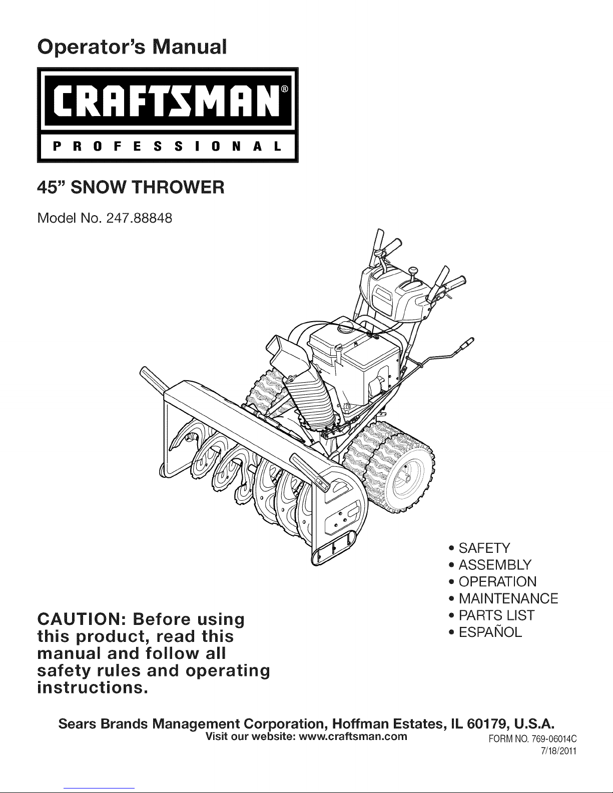
45" SNOW THROWER
Model No. 247.88848
CAUTION: Before using
this product, read this
manual and follow all
safety rules and operating
instructions.
Sears Brands Management Corporation, Hoffman Estates, IL 60179, U.S.A.
Visit our website: www.craftsman.com FORMNO.769-06014C
, SAFETY
, ASSEMBLY
, OPERATION
, MAINTENANCE
, PARTS LIST
o ESPANOL
7/18/2011
Page 2
WarrantyStatement..................................Page2
SafeOperation Practices .......................... Page 3
Safety Labels ............................................ Page 7
Assembly .................................................. Page 8
Operation .................................................. Page 14
Service and Maintenance ......................... Page 19
Off-Season Storage .................................. Page 27
Troubleshooting ........................................ Page 28
Parts List ................................................... Page 29
Repair Protection Agreement ................... Page 49
Espa_ol ..................................................... Page 50
Service Numbers ...................................... Back Cover
CRAFTSMAN PROFESSIONAL TWO YEAR FULL WARRANTY
FORTWOYEARSfromthe dateof purchase,this productiswarrantedagainstanydefectsin materialor workmanship.A defectiveproductwill
receivefreerepairorreplacementif repairisunavailable.
Thiswarrantyappliesfor onlyoneyearfromthedateof purchaseifthis productiseverusedwhileprovidingcommercialservicesor if rentedto
anotherperson.
Forwarrantycoveragedetailsto obtainfreerepairor replacement,visitthewebsite:www.craftsman.com
Thiswarranty coversONLYdefects inmaterial andworkmanship. Warrantycoverage does NOTinclude:
• Expendableitemsthatcanwearoutfromnormalusewithinthewarrantyperiod,includingbut notlimitedto augers,augerpaddles,drift
cutters,skidshoes,shaveplate,shearpins,sparkplug,aircleaner,belts,andoil filter.
• Standardmaintenanceservicing,oilchanges,or tune-ups.
• Tire replacementor repaircausedby puncturesfromoutsideobjects,suchasnails,thorns,stumps,orglass.
• Tireor wheelreplacementor repairresultingfromnormalwear,accident,orimproperoperationormaintenance.
• Repairsnecessarybecauseof operatorabuse,includingbutnot limitedtodamagecausedbyover-speedingthe engine,orfromimpacting
objectsthatbendthe frame,augershaft,etc.
• Repairsnecessarybecauseof operatornegligence,includingbutnotlimitedto,electricalandmechanicaldamagecausedby improper
storage,failureto usethepropergradeandamountofengineoil,or failureto maintaintheequipmentaccordingtotheinstructionscontained
intheoperator'smanual.
• Engine(fuelsystem)cleaningorrepairscausedbyfueldeterminedto becontaminatedoroxidized(stale).Ingeneral,fuelshouldbeused
within30 daysof itspurchasedate.
• Normaldeteriorationandwearoftheexteriorfinishes,or productlabelreplacement.
Thiswarrantygivesyouspecificlegalrights,andyou mayalsohaveotherrightswhichvaryfromstatetostate.
Sears Brands Management Corporation, Hoffman Estates, IL 60179
EngineOilType: 5W-30
EngineOilCapacity: 37ounces
FuelCapacity: Approx.5Quarts
SparkPlug: F6RTC(951-10292)
SparkPlugGap: .020"to.030"
©KCDIR LLC
ModelNumber.................................................................
Serial Number .................................................................
Dateof Purchase.............................................................
Recordthemodelnumber,serialnumber
anddateof purchaseabove
2
Page 3
Thissymbolpointsout importantsafetyinstructionswhich,if not
followed,couldendangerthepersonalsafetyand/orpropertyof
yourselfandothers. Readandfollowall instructionsin thismanual
beforeattemptingtooperatethismachine.Failuretocomplywith
theseinstructionsmayresultin personalinjury.Whenyouseethis
symbol,HEEDITSWARNING!
Thismachinewasbuiltto beoperatedaccordingtothesafeopera-
tionpracticesinthis manual.Aswithanytypeof powerequipment,
carelessnessorerroron thepartofthe operatorcanresultin serious
injury.Thismachineiscapableofamputatingfingers,hands,toes
andfeetandthrowingdebris.Failuretoobservethefollowingsafety
instructionscouldresultin seriousinjuryor death.
CALIFORNIA PROPOSITION 65
EngineExhaust,someof itsconstituents,andcertainvehicle
componentscontainoremitchemicalsknownto StateofCalifornia
tocausecancerandbirthdefectsorotherreproductiveharm,
TRAiNiNG
• Read,understand,andfollowallinstructionson themachineand
in themanual(s)beforeattemptingto assembleandoperate.
Failuretodo socan resultinseriousinjurytotheoperatorand/
orbystanders.Keepthismanualin a safeplaceforfutureand
regularreferenceandfor orderingreplacementparts.
• Befamiliarwithall controlsandtheirproperoperation.Knowhow
tostopthe machineanddisengagethemquickly.
• Neverallowchildrenunder14yearsof agetooperatethis
machine.Children14andover shouldreadandunderstandthe
instructionsandsafeoperationpracticesin thismanualandon
themachineandbe trainedandsupervisedbyanadult.
Neverallowadultsto operatethismachinewithoutproper
instruction.
• Thrownobjectscancauseseriouspersonalinjury.Planyour
snow-throwingpatterntoavoiddischargeof materialtoward
roads,bystandersandthe like.
Keepbystanders,petsandchildrenat least75feetfromthe
machinewhileitisin operation.Stopmachineifanyoneenters
thearea.
• Exercisecautiontoavoidslippingorfalling,especiallywhen
operatinginreverse.
Your Responsibility--Restrict the useof thispowermachineto
personswhoread,understandandfollowthewarningsand instruc-
tionsin thismanualandon the machine.
SAVE THESE INSTRUCTIONS!
PREPARATION
Thoroughlyinspecttheareawheretheequipmentisto beused.
Removeall doormats,newspapers,sleds,boards,wiresandother
foreignobjects,whichcouldbe trippedoverorthrownbythe auger/
impeller.
• Alwayswearsafetyglassesor eyeshieldsduringoperationand
whileperformingan adjustmentor repairto protectyoureyes.
Thrownobjectswhichricochetcancauseseriousinjurytothe
eyes.
Donot operatewithoutwearingadequatewinteroutergarments.
Donot wearjewelry,longscarvesorotherlooseclothing,which
couldbecomeentangledin movingparts.Wearfootwearwhich
willimprovefootingonslipperysurfaces.
Usea groundedthree-wireextensioncordand receptacleforall
machineswithelectricstartengines.
Disengageallcontrolleversbeforestartingtheengine.
Adjustcollectorhousingheighttocleargravelorcrushedrock
surfaces.
• Neverattempttomakeanyadjustmentswhileengineis running,
exceptwherespecificallyrecommendedintheoperator'smanual.
Letengineandmachineadjustto outdoortemperaturebefore
startingtoclearsnow.
3
Page 4
SafeHandling of Gasoline
Toavoidpersonalinjuryor propertydamageuseextremecarein
handlinggasoline.Gasolineisextremelyflammableandthevaporsare
explosive.Seriouspersonalinjurycanoccurwhengasolineis spilled
onyourselforyourclotheswhichcan ignite.Washyourskinand
changeclothesimmediately.
• Useonlyanapprovedgasolinecontainer.
• Extinguishall cigarettes,cigars,pipesandothersources
ofignition.
• Neverfuelmachineindoors.
• Neverremovegascaporaddfuelwhiletheengineishot
or running.
• Allowengineto coolat leasttwo minutesbeforerefueling.
• Neveroverfill fueltank. Filltankto no morethan1/2inch
belowbottomoffiller neckto providespaceforfuel
expansion.
• Replacegasolinecapandtightensecurely.
• Ifgasolineis spilled,wipeit offtheengineandequipment.
Movemachinetoanotherarea.Wait5 minutesbefore
startingtheengine.
• Neverstorethemachineorfuel containerinsidewhere
thereis anopenflame,sparkor pilotlight(e.g.furnace,
waterheater,spaceheater,clothesdryeretc.).
• Allowmachinetocoolat least5 minutesbeforestoring.
• Neverfillcontainersinsidea vehicleor ona truckortrailer
bedwitha plasticliner.Alwaysplacecontainersonthe
groundawayfromyourvehiclebeforefilling.
• If possible,removegas-poweredequipmentfromthetruck
ortrailerand refueliton the ground.Ifthisis notpossible,
thenrefuelsuchequipmentona trailerwitha portable
container,ratherthanfromagasolinedispensernozzle.
• Keepthenozzleincontactwiththe rimofthefueltankor
containeropeningatalltimesuntilfuelingiscomplete.Do
notuse a nozzlelock-opendevice.
OPERATION
• Do notputhandsorfeetnear rotatingparts,in theauger/impeller
housingorchuteassembly.Contactwiththe rotatingpartscan
amputatehandsandfeet.
• Theauger/impellercontrolleverisasafetydevice.Neverbypass
itsoperation.Doingsomakesthe machineunsafeandmaycause
personalinjury.
• Thecontrolleversmustoperateeasilyin bothdirectionsand
automaticallyreturntothedisengagedpositionwhenreleased.
• Neveroperatewitha missingordamagedchuteassembly.Keep
all safetydevicesinplaceandworking.
• Neverrunanengineindoorsor ina poorlyventilatedarea.Engine
exhaustcontainscarbonmonoxide,anodorlessanddeadlygas.
• Do notoperatemachinewhileundertheinfluenceof alcoholor
drugs.
• Mufflerandenginebecomehotandcan causea burn.Do not
touch.Keepchildrenaway.
• Exerciseextremecautionwhenoperatingonorcrossinggravel
surfaces.Stayalertforhiddenhazardsortraffic.
• Exercisecautionwhenchangingdirectionandwhileoperatingon
slopes.Do notoperateon steepslopes.
• Planyoursnow-throwingpatternto avoiddischargetowards
windows,walls,carsetc.Thus,avoidingpossibleproperty
damageorpersonalinjurycausedby a ricochet.
• Neverdirectdischargeat children,bystandersandpetsorallow
anyoneinfrontof themachine.
• Donot overloadmachinecapacitybyattemptingtoclearsnowat
toofastof a rate.
• Neveroperatethismachinewithoutgoodvisibilityorlight.Always
be sureof yourfootingand keepa firmholdon thehandles.Walk,
neverrun.
• Disengagepowertotheauger/impellerwhentransportingor not
in use.
• Neveroperatemachineathightransportspeedson slippery
surfaces.Lookdownand behindandusecarewhenbackingup.
• Ifthemachineshouldstartto vibrateabnormally,stopthe engine,
disconnectthe sparkplugwireandgroundit againsttheengine.
Inspectthoroughlyfor damage.Repairanydamagebefore
startingandoperating.
• Disengageallcontrolleversandstopenginebeforeyouleave
theoperatingposition(behindthehandles).Waituntiltheauger/
impellercomestoa completestopbeforeuncloggingthechute
assembly,makinganyadjustments,or inspections.
• Neverputyourhandinthedischargeor collectoropenings.Do
notunclogchuteassemblywhileengineis running.Shutoff
engineand remainbehindhandlesuntilall movingpartshave
stoppedbeforeunclogging.
• Useonlyattachmentsandaccessoriesapprovedbythemanufac-
turer(e.g.wheelweights,tire chains,cabsetc.).
• Whenstartingengine,pullcordslowlyuntilresistanceisfelt,then
pull rapidly.Rapidretractionofstartercord(kickback)willpull
handandarmtowardenginefasterthanyoucanletgo.Broken
bones,fractures,bruisesorsprainscouldresult.
• Ifsituationsoccurwhichare notcoveredinthis manual,usecare
andgoodjudgment.
• Forin-warrantysafety,operationor maintenancequestions,or to
orderpartsandscheduleservice,call 1-800-4-MY-HOME.
CLEARING A CLOGGED DISCHARGE CHUTE
Handcontactwiththe rotatingimpellerinsidethedischargechute
is the mostcommoncauseofinjuryassociatedwithsnowthrowers.
Neveruseyourhandtocleanoutthedischargechute.
Toclear thechute:
1. SHUTTHEENGINEOFF!
2. Wait 10secondstobe surethe impellerbladeshavestopped
rotating.
3. Alwaysusea clean-outtool,notyourhands.
4
Page 5
MAINTENANCE & STORAGE
• Nevertamperwithsafetydevices.Checktheirproperoperation
regularly.Refertothemaintenanceandadjustmentsectionsof
thismanual.
• Beforecleaning,repairing,or inspectingmachinedisengageall
controlleversandstoptheengine.Waituntiltheauger/impeller
cometoa completestop.Disconnectthe sparkplugwireand
groundagainsttheengineto preventunintendedstarting.
Checkboltsand screwsforpropertightnessatfrequentintervals
tokeepthemachineinsafeworkingcondition.Also,visually
inspectmachineforanydamage.
Donotchangetheenginegovernorsettingor over-speedthe
engine.Thegovernorcontrolsthe maximumsafeoperatingspeed
ofthe engine.
Snowthrowershaveplatesandskidshoesaresubjecttowear
anddamage.Foryoursafetyprotection,frequentlycheckall
componentsandreplacewithoriginalequipmentmanufacturer's
(OEM)partsonlyaslistedinthe Partspagesof thisoperator's
manual.Useofpartswhichdonot meettheoriginalequipment
specificationsmayleadto improperperformanceandcompro-
misesafety!
Checkcontrolleversperiodicallytoverifytheyengageanddisen-
gageproperlyandadjust,ifnecessary.Referto theadjustment
sectioninthisoperator'smanualforinstructions.
Maintainorreplacesafetyandinstructionlabels,as necessary.
Observeproperdisposallawsand regulationsforgas,oil,etc. to
protecttheenvironment.
Priorto storing,runmachineafewminutestoclearsnowfrom
machineandpreventfreezeupof auger/impeller.
Neverstorethemachineorfuel containerinsidewherethereisan
openflame,sparkorpilot lightsuchas a waterheater,furnace,
clothesdryeretc.
Alwaysrefertothe operator'smanualforproperinstructionson
off-seasonstorage.
Checkfuelline,tank, cap,andfittingsfrequentlyforcracksor
leaks.Replaceif necessary.
Donotcrankenginewithsparkplugremoved.
AccordingtotheConsumerProductsSafetyCommission(CPSC)
andtheU.S.EnvironmentalProtectionAgency(EPA),thisproduct
hasan AverageUsefulLifeof seven(7)years,or 60 hoursof
operation.At theendof theAverageUsefulLifehavethe machine
inspectedannuallybyan authorizedservicedealerto ensurethat
allmechanicalandsafetysystemsareworkingproperlyand not
wornexcessively.Failuretodo so canresultinaccidents,injuries
ordeath.
DO NOT MODIFY ENGINE
Toavoidseriousinjuryor death,do not modifyengineinany way.
Tamperingwiththegovernorsettingcanleadto a runawayengineand
causeitto operateat unsafespeeds.Nevertamperwithfactorysetting
ofenginegovernor.
NOTICE REGARDING EMiSSiONS
EngineswhicharecertifiedtocomplywithCaliforniaandfederal
EPAemissionregulationsforSORE(SmallOffRoadEquipment)are
certifiedto operateonregularunleadedgasoline,and mayinclude
thefollowingemissioncontrolsystems:EngineModification(EM),
OxidizingCatalyst(OC),SecondaryAirInjection(SAI)and ThreeWay
Catalyst(TWO)if soequipped.
SPARK ARRESTOR
Thismachineisequippedwithaninternalcombustionengineand
shouldnotbe usedonor nearany unimprovedforest-covered,
brush-coveredorgrass-coveredlandunlesstheengine'sexhaust
systemisequippedwitha sparkarrestormeetingapplicablelocalor
statelaws(if any)
Ifa sparkarrestorisused,it shouldbe maintainedin effectiveworking
orderbytheoperator.Inthe StateofCaliforniatheaboveisrequired
bylaw (Section4442ofthe CaliforniaPublicResourcesCode).Other
statesmayhavesimilarlaws. Federallawsapplyonfederallands.
A sparkarrestorforthemufflerisavailablethroughyournearestSears
PartsandRepairServiceCenter.
Page 6
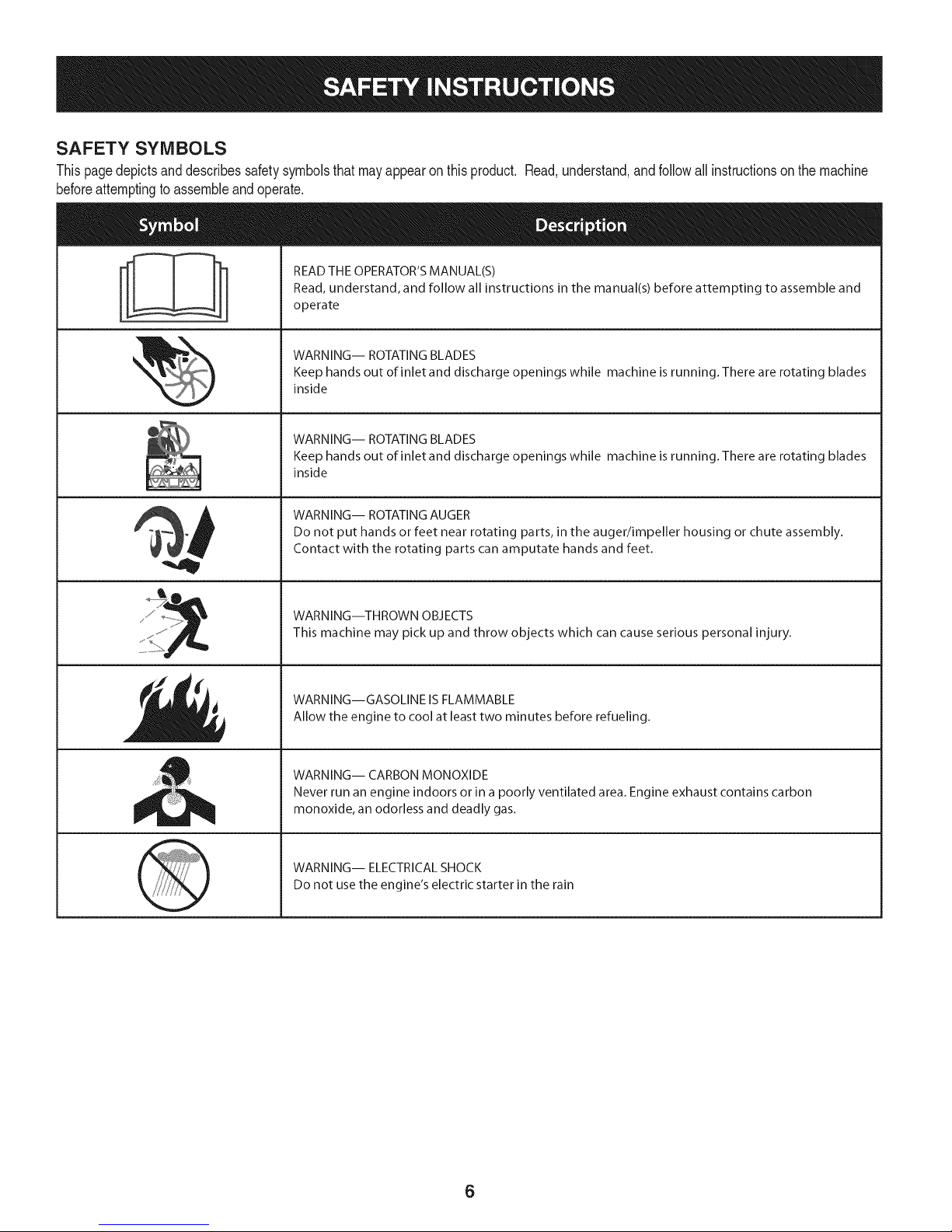
SAFETY SYMBOLS
Thispagedepictsanddescribessafetysymbolsthatmayappearonthisproduct. Read,understand,andfollowall instructionsonthemachine
beforeattemptingtoassembleandoperate.
READ THE OPERATOR'S MANUAL(S)
i
. +
i
Read, understand, and follow all instructions in the manual(s) before attempting to assemble and
operate
WARNING-- ROTATING BLADES
Keep hands out of inlet and discharge openings while machine is running. There are rotating blades
inside
WARNING-- ROTATING BLADES
Keep hands out of inlet and discharge openings while machine is running. There are rotating blades
inside
WARNING-- ROTATING AUGER
Do not put hands or feet near rotating parts, in the auger/impeller housing or chute assembly.
Contact with the rotating parts can amputate hands and feet.
'JIp
WARNING--THROWN OBJECTS
This machine may pick up and throw objects which can cause serious personal injury.
WARNING--GASOLINE IS FLAMMABLE
Allow the engine to cool at least two minutes before refueling.
WARNING-- CARBON MONOXIDE
Never run an engine indoors or in a poorly ventilated area. Engine exhaust contains carbon
monoxide, an odorless and deadly gas+
WARNING-- ELECTRICAL SHOCK
Do not use the engine's electric starter in the rain
6
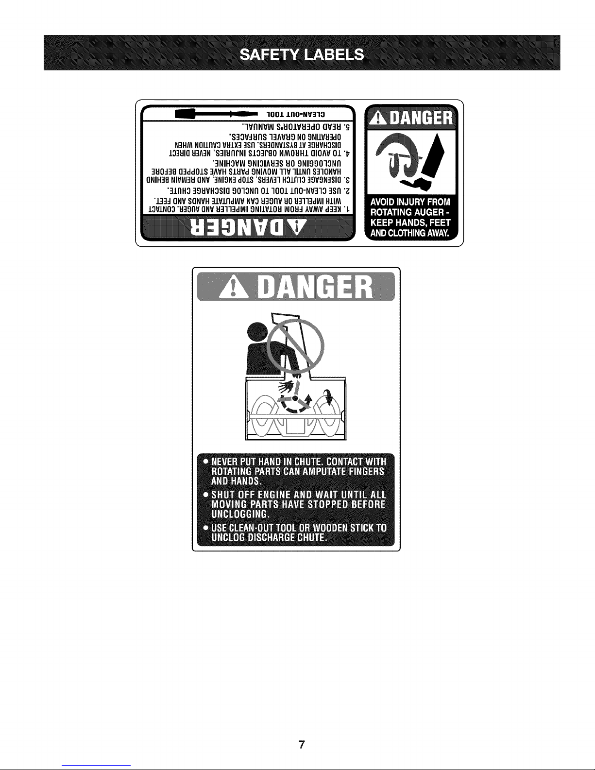
Page 7
r
100/.LIIO-NV:IIO
"lVflNV_ S,UOIVU3dOQV3H"G
"S3OV_IJflS]3AVUONO9NIIV_J3dO
N3HMNOIIflVOVSIX]qsfl"S9]ONVIS181V]98VHOSIO
10381083A3N'S]IUflrNI SI03PgoNMOUHIQIOAV01 "_
"3NIHOV_ONIOIA83SUOONIOOO]ONfl
]UO_38O3ddOIS]AVHSlHPd9NIAOW11VlllNfl S]IQNVH
ONIH]8NIVW3UONV']NION]dOlS'88]A]1HOlnlo]9VON]SIO"8
"]lnHg ]gHVHOSIO9010Nfl01 1001lflO-NP]lO ]Sfl "Z
"l]]d ONVSONVH]lPlnd_P NVOH3onvuoHq]l]d_JIHIIM
IOVINO0"u39npONV_J3113dWI9NllVIOU_JOH_IVMVd]3H "L
7
Page 8
NOTE:Referencesto rightorleft sideofthe snowthrowerare
determinedfromthe operatingpositionlookingforwardtothe frontof
themachine.
REMOVING FROM CRATE
1. Removescrewsfromthebottomofthecratesecuringthesides,
andendsof theshippingcrate.
2. Liftoff thetopoff ofthe crateandsetoutof thewayofthe
assemblyarea.
3. Removeanddiscardplasticbagthatcoversunit.
4. Removeanyloosepartsincludedwithunit(e.g.,Operator's
Manual,etc.).
5. Pushdownonthelowerhandleandpullunitbackout ofcrate.
6. Makecertainthecratehas beencompletelyemptiedbefore
discardingit.
ASSEMBLY
1. Makecertainthe springsatthelowerendofthe augeranddrive
cablesaresecurelyhookedintotheir respectiveactuator
bracketsbeforepivotingthehandleupward.Referto Fig. 10.
a. Placethe speedselectorshiftleverin theF6 position.
b. Cutthecabletiesecuringthetwo piecechutecrankto the
lowerhandle.Thecable tieis usedfor shippingpurposes.
c. Removethe upperwingknobandcarriageboltfromeach
sideof thelowerhandle.Pulluponupperhandleasshown
in Fig.1.Alignupperhandlewiththe lowerhandle.Again,
makecertainthespringsat thelowerendofthe augerand
drivecablesaresecurelyhookedintotheirrespective
actuatorbrackets.Also,removeanyrubberbandssecuring
thecablesto thewing nuts.
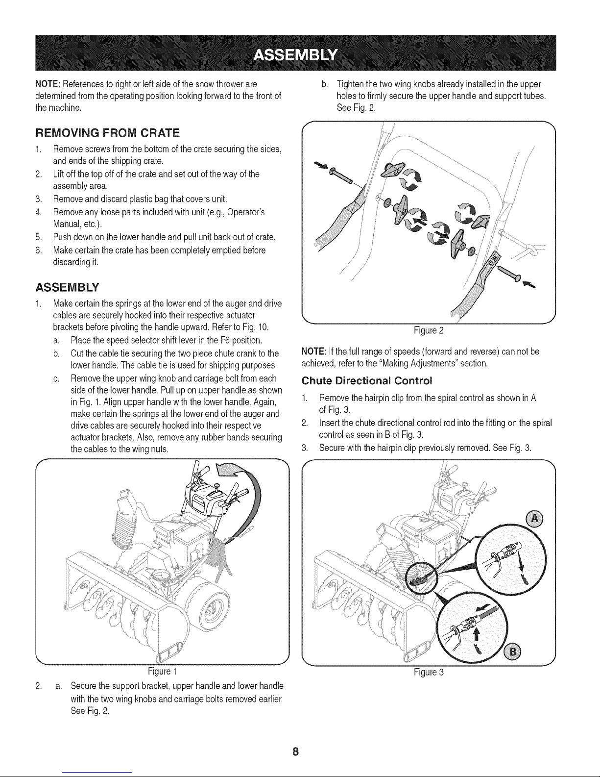
Tightenthetwowingknobsalreadyinstalledintheupper
holesto firmlysecurethe upperhandleandsupporttubes.
See Fig.2.
f
!
{
/
/
Figure2
NOTE:Ifthe fullrangeof speeds(forwardand reverse)cannotbe
achieved,refertothe "MakingAdjustments"section.
Chute Directional Control
1. Removethehairpinclipfromthespiralcontrolas showninA
of Fig.3.
2. Insertthechutedirectionalcontrolrodintothefittingonthe spiral
controlas seenin Bof Fig.3.
3. Securewiththe hairpinclippreviouslyremoved.SeeFig.3.
\
Figure1
2.
a.
Securethesupportbracket,upperhandleandlowerhandle
withthetwo wingknobsandcarriageboltsremovedearlier.
SeeFig.2.
Figure3
8
Page 9
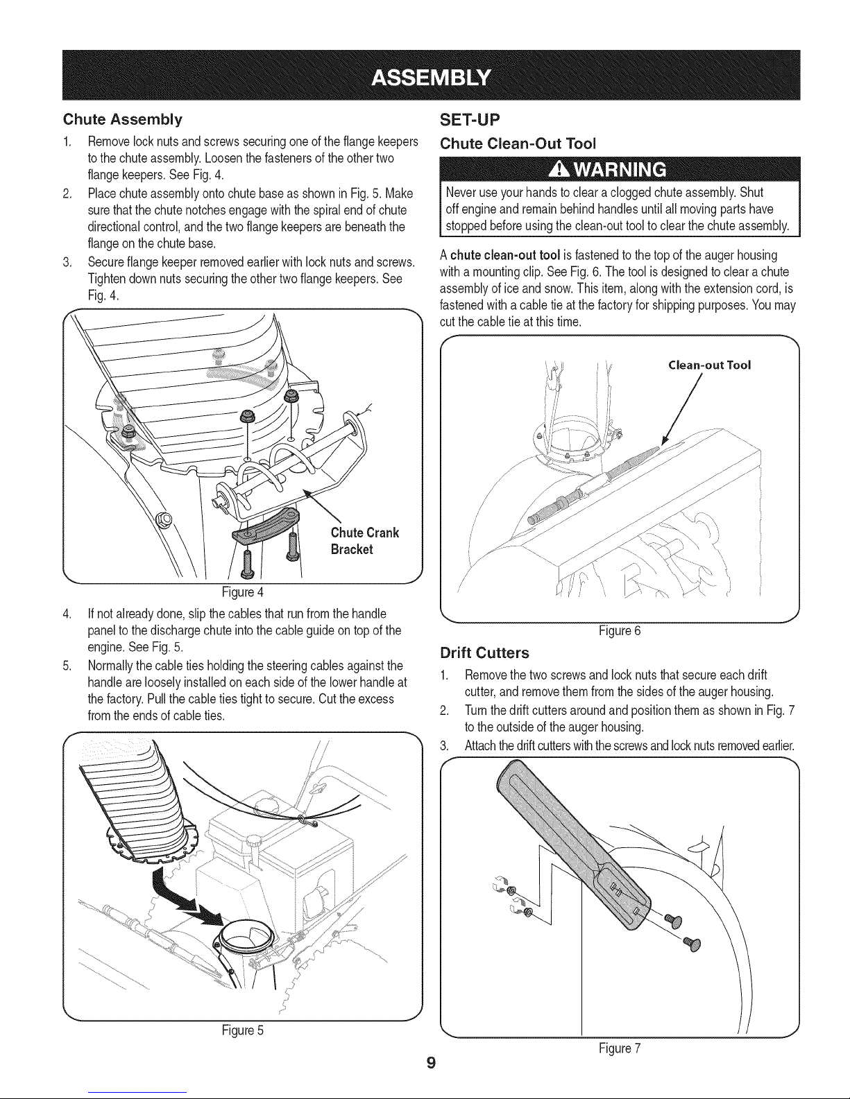
Chute Assembly
1, Removelocknutsandscrewssecuringoneoftheflangekeepers
tothe chuteassembly,Loosenthefastenersoftheothertwo
flangekeepers,SeeFig,4,
2, Placechuteassemblyontochutebaseas showninFig,5,Make
surethatthe chutenotchesengagewiththe spiralendof chute
directionalcontrol,andthetwoflangekeepersarebeneaththe
flangeonthe chutebase,
3, Secureflangekeeperremovedearlierwithlocknutsandscrews,
Tightendownnutssecuringtheothertwoflangekeepers.See
Fig.4.
SET-UP
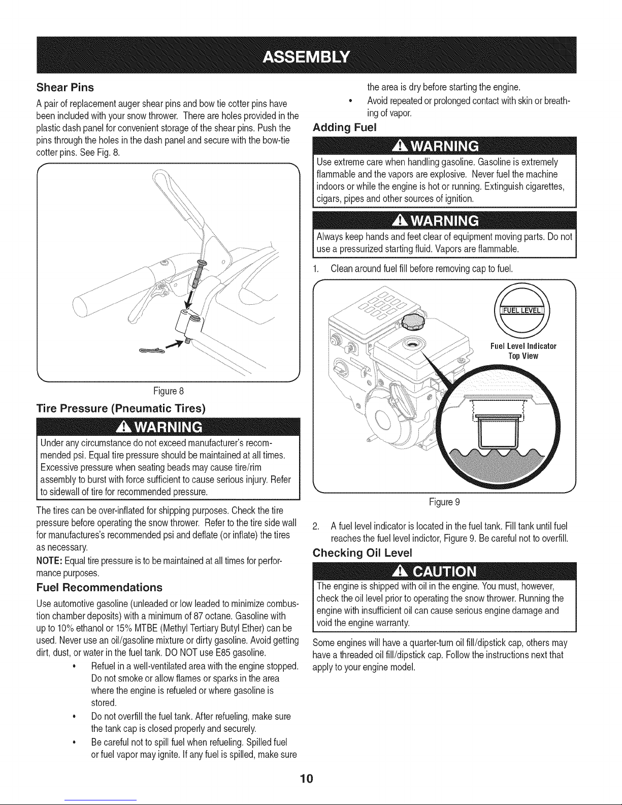
Chute Clean=Out Tool
Neveruseyourhandsto cleara cloggedchuteassembly.Shut
offengineand remainbehindhandlesuntilall movingpartshave
stoppedbeforeusingtheclean-outtooltoclearthechuteassembly,
A chuteclean-outtool isfastenedtothetopof theaugerhousing
witha mountingclip.SeeFig.6.Thetoolisdesignedtocleara chute
assemblyofice andsnow.Thisitem,alongwiththeextensioncord,is
fastenedwitha cabletieat thefactoryfor shippingpurposes.Youmay
cut thecable tieat thistime.
Clean=out Tool
Figure4
.
If notalreadydone,slipthecablesthat runfromthe handle
paneltothe dischargechuteintothecableguideontopof the
engine.SeeFig.5.
.
Normallythecabletiesholdingthe steeringcablesagainstthe
handlearelooselyinstalledoneachsideofthelowerhandleat
thefactory.Pullthecableties tighttosecure.Cuttheexcess
fromtheendsof cableties.
\,
//
//
(,
Figure6
Drift Cutters
1.
Removethetwoscrewsandlocknutsthatsecureeachdrift
cutter,and removethemfromthesidesoftheaugerhousing.
2.
Turnthedrift cuttersaroundandpositionthemasshownin Fig.7
tothe outsideofthe augerhousing.
3.
Attachthedriftcutterswiththescrewsandlocknutsremovedearlier.
J
J
Figure7
9
Page 10
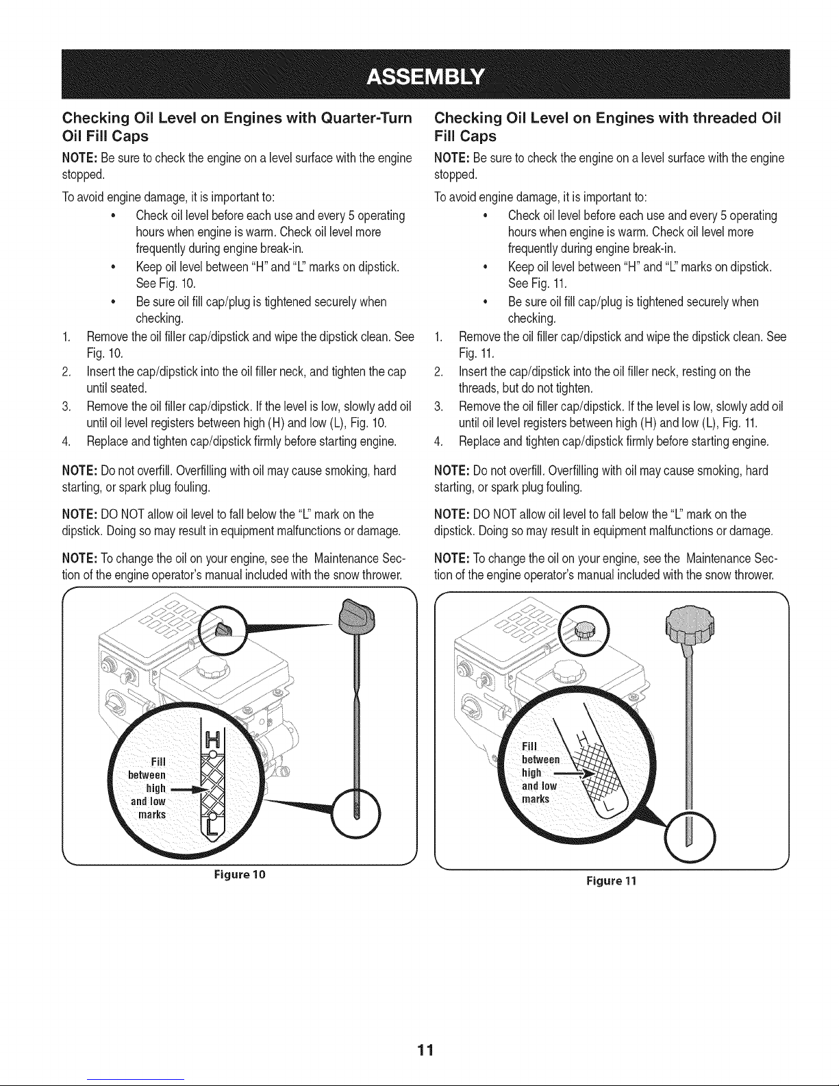
Shear Pins
A pairof replacementaugershearpinsandbowtiecotterpinshave
beenincludedwithyour snowthrower.Thereareholesprovidedinthe
plasticdashpanelforconvenientstorageof theshearpins.Pushthe
pinsthroughtheholesin thedash panelandsecurewiththebow-tie
cotterpins.See Fig.8.
theareais drybeforestartingtheengine.
• Avoidrepeatedor prolongedcontactwithskinorbreath-
ingofvapor.
Adding Fuel
Useextremecarewhenhandlinggasoline.Gasolineisextremely
flammableandthe vaporsareexplosive.Neverfuelthemachine
indoorsorwhile theengineis hotor running.Extinguishcigarettes,
cigars,pipesandothersourcesofignition.
Alwayskeephandsandfeetclear ofequipmentmovingparts.Donot
usea pressurizedstartingfluid.Vaporsareflammable.
Cleanaroundfuel fillbeforeremovingcaptofuel.
Fuel Level Indicator
TopView
Figure8
Tire Pressure (Pneumatic Tires)
Underanycircumstancedonotexceedmanufacturer'srecom-
mendedpsi.Equaltire pressureshouldbemaintainedatalltimes.
Excessivepressurewhenseatingbeadsmaycausetire/rim
assemblytoburstwithforcesufficienttocauseseriousinjury.Refer
to sidewalloftirefor recommendedpressure.
Thetirescan beover-inflatedfor shippingpurposes.Checkthetire
pressurebeforeoperatingthe snowthrower.Referto thetire sidewall
for rnanufactures'srecommendedpsianddeflate(or inflate)thetires
as necessary.
NOTE:Equaltirepressureisto bemaintainedatalltimesforperfor-
mancepurposes.
Fuel Recommendations
Useautomotivegasoline(unleadedor lowleadedto minimizecombus-
tionchamberdeposits)witha minimumof87 octane.Gasolinewith
upto 10%ethanolor 15%MTBE(MethylTertiaryButylEther)canbe
used.Neverusean oil/gasolinemixtureordirty gasoline.Avoidgetting
dirt, dust,or waterinthe fueltank.DONOTuse E85gasoline.
• Refuelina well-ventilatedareawiththeenginestopped.
Donot smokeorallowflamesor sparksin thearea
wherethe engineis rdueledor wheregasolineis
stored.
• Donot overfillthefueltank.Afterrefueling,makesure
thetankcap isclosedproperlyandsecurely.
• Becarefulnotto spillfuel whenrefueling.Spilledfuel
or fuelvapor mayignite.Ifanyfuelis spilled,makesure
Figure9
2. A fuellevelindicatorislocatedin thefueltank.Filltankuntilfuel
reachesthefuellevelindictor,Figure9.Becarefulnottooverfill.
Checking Oil Level
Theengineis shippedwithoil in theengine.Youmust,however,
checkthe oil levelpriorto operatingthe snowthrower.Runningthe
enginewith insufficientoil cancauseseriousenginedamageand
voidtheenginewarranty.
Someengineswillhavea quarter-turnoilfill/dipstickcap,othersmay
havea threadedoilfill/dipstickcap. Followthe instructionsnextthat
applyto yourenginemodel.
10
Page 11
Checking Oil Level on Engines with Quarter=Turn
Oil Fill Caps
NOTE:Besuretochecktheengineona levelsurfacewiththeengine
stopped.
Toavoidenginedamage,it isimportantto:
• Checkoillevelbeforeeachuseandevery5 operating
hourswhenengineiswarm.Checkoillevelmore
frequentlyduringenginebreak-in.
• Keepoil levelbetween"H"and'%'marksondipstick.
SeeFig.10.
• Besureoil fillcap/plugistightenedsecurelywhen
checking.
1. Removetheoil fillercap/dipstickandwipethedipstickclean.See
Fig.10.
2. Insertthe cap/dipstickintotheoil fillerneck,andtightenthecap
untilseated.
3. Removetheoil fillercap/dipstick.Ifthelevelislow,slowlyaddoil
untiloil levelregistersbetweenhigh(H) andlow(L), Fig.10.
4. Replaceandtightencap/dipstickfirmlybeforestartingengine.
Checking Oil Level on Engines with threaded Oil
Fill Caps
NOTE:Besuretochecktheengineon a levelsurfacewiththe engine
stopped.
Toavoidenginedamage,itis importantto:
• Checkoillevelbeforeeachuseandevery5 operating
hourswhenengineiswarm.Checkoil levelmore
frequentlyduringenginebreak-in.
• Keepoillevelbetween"H"and"L"marksondipstick.
SeeFig.11.
• Besureoilfill cap/plugistightenedsecurelywhen
checking.
1. Removetheoilfillercap/dipstickandwipethedipstickclean.See
Fig.11.
2. Insertthecap/dipstickintothe oilfillerneck, restingon the
threads,butdo nottighten.
3. Removethe oilfillercap/dipstick.Ifthe levelislow,slowlyaddoil
untiloillevel registersbetweenhigh(H)andlow (L),Fig.11.
4. Replaceandtightencap/dipstickfirmlybeforestartingengine.
NOTE:Donotoverfill.Overfillingwithoil maycausesmoking,hard
starting,or sparkplugfouling.
NOTE:DONOTallowoil leveltofall belowthe"L"markonthe
dipstick.Doingsomayresultinequipmentmalfunctionsordamage.
NOTE:Tochangethe oilon yourengine,seethe MaintenanceSec-
tionof theengineoperator'smanualincludedwiththesnowthrower.
NOTE:Do notoverfill.Overfillingwithoilmaycausesmoking,hard
starting,orsparkplugfouling.
NOTE:DO NOTallowoil leveltofall belowthe "L"markon the
dipstick.Doingsomayresultinequipmentmalfunctionsordamage.
NOTE:Tochangetheoil onyourengine,seethe MaintenanceSec-
tionof theengineoperator'smanualincludedwiththe snowthrower.
Figure 10
Figure 11
11
Page 12
ADJUSTMENTS
Skid Shoes
Itisnot recommendedthatyou operatethissnowthrowerongravel
asit caneasilypickupandthrowloosegravel,causingpersonal
injuryor damagetothe snowthrowerandsurroundingproperty.
Thesnowthrowerskidshoesareadjustedupwardatthefactory
forshippingpurposes.Adjustthemdownwardpriortooperatingthe
machine.
Forclosesnowremovalona smoothsurface,adjustthe skidshoesso
thattheshaveplateonthebottomof the augerhousingisjust offthe
ground.
Adjusttheskidshoesto a lowerpositionto raisethe shaveplateoff the
groundwhenclearingunevenareas,suchas a ribbontypedrivewayor
agraveldriveway
NOTE:If youchoosetooperatethesnowthrowerona gravelsurface,
keepthe skidshoesin positionformaximumclearancebetweenthe
groundandtheshaveplate.
To adjust the skid shoes:
1. Loosenthesixhexnuts(threeoneachside)andcarriagebolts.Move
skidshoestodesiredposition.SeeFig.12.
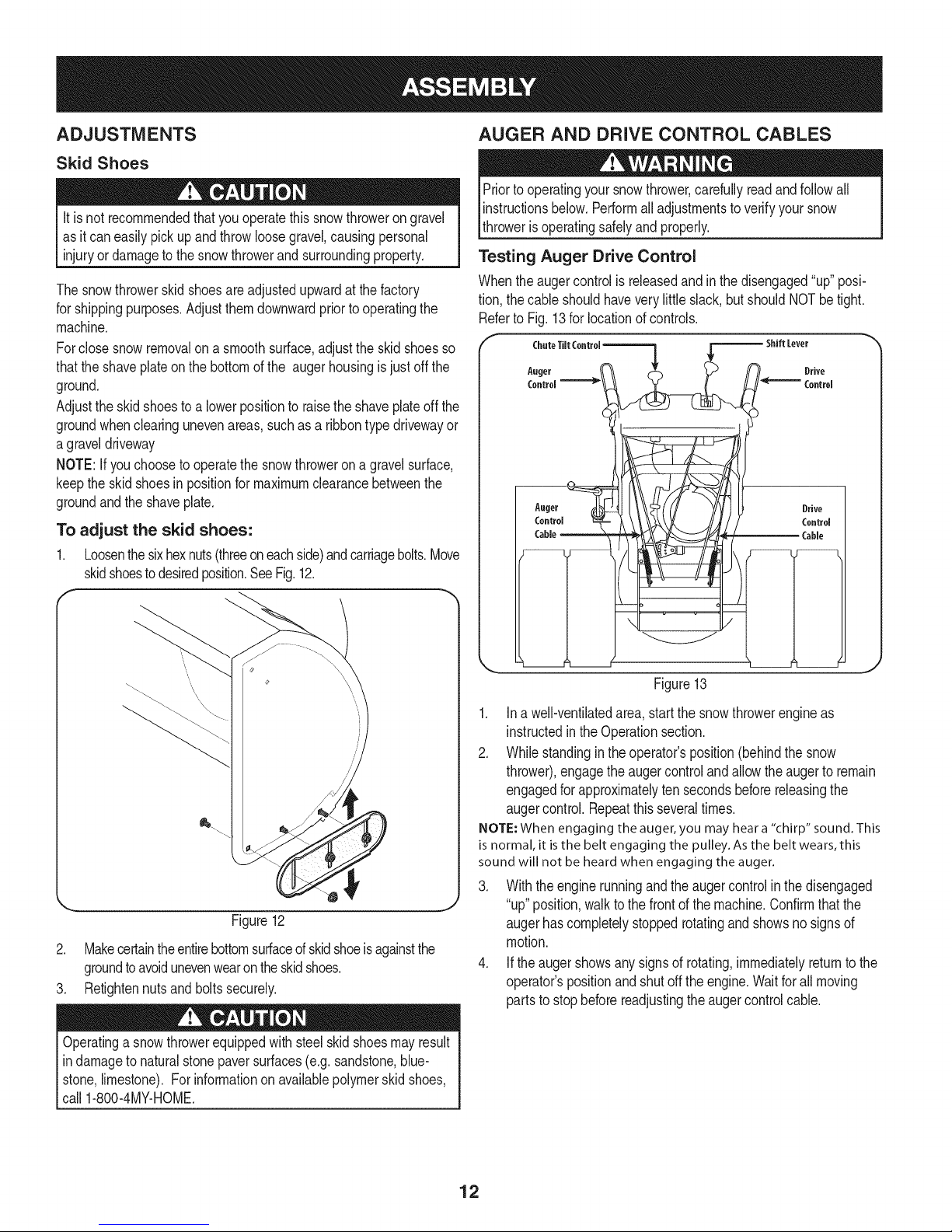
AUGER AND DRIVE CONTROL CABLES
Priortooperatingyour snowthrower,carefullyreadandfollowall
instructionsbelow.Performalladjustmentstoverifyyoursnow
throwerisoperatingsafelyandproperly.
Testing Auger Drive Control
Whenthe augercontrolisreleasedandinthedisengaged"up" posi-
tion,thecableshouldhaveverylittleslack,butshouldNOTbetight.
RefertoFig.13for locationof controls.
r c,.,o,,,co..o,-.--=q F------'"'"Lev°'
A.ge, & n. O,,vo
X..__J_ H '°°"°'
Aoter _}J__ Drive
Figure12
2. Makecertaintheentirebottomsurfaceofskidshoeisagainstthe
groundtoavoidunevenwearontheskidshoes.
3. Retightennutsand boltssecurely.
Operatinga snowthrowerequippedwithsteelskidshoesmayresult
indamageto naturalstonepaversurfaces(e.g.sandstone,blue-
stone,limestone).For informationon availablepolymerskidshoes,
call1-800-4MY-HOME.
Figure13
1. Ina well-ventilatedarea,startthe snowthrowerengineas
instructedintheOperationsection.
2. Whilestandinginthe operator'sposition(behindthesnow
thrower),engagetheaugercontrolandallowtheaugerto remain
engagedforapproximatelyten secondsbeforereleasingthe
augercontrol.Repeatthisseveraltimes.
NOTE: When engaging the auger, you may hear a "chirp" sound. This
is normal, it is the belt engaging the pulley. As the belt wears, this
sound will not be heard when engaging the auger.
3. Withtheenginerunningandthe augercontrolin thedisengaged
J
"up"position,walktothe frontofthe machine.Confirmthatthe
augerhascompletelystoppedrotatingandshowsnosignsof
motion.
4. Iftheaugershowsanysignsofrotating,immediatelyreturntothe
operator'spositionandshutofftheengine.Waitforall moving
partstostopbeforereadjustingtheaugercontrolcable.
12
Page 13
Testing Wheel Drive Control & Speed Selector Lever
RefertoFig.13forlocationofcontrols.
1. Movethespeedselectorshiftleverintosixth(6)position.
2. Withthewheeldrivecontrolreleased,pushthesnowthrowerforward,
thenpullitback.Themachineshouldmovefreely.
3. Engagethedrivecontrolandattempttomovethemachineboth
forwardandback,resistanceshouldbefelt.
4. Movethespeedselectorshiftleverintothefastreverse(R2)position
andrepeattheprevioustwosteps.
Ifyouexperiencedresistancerollingtheunit,eitherwhenrepositioning
thespeedselectorshiftleverfrom6to R2orwhenattemptingtomovethe
machinewiththedrivecontrolreleased,adjustthedrivecontrolimmedi-
ately.SeeAdjustingDriveandAugerControls.
Adjusting Wheel Drive & Auger Controls
1. Frombeneaththehandle,pulldownwardontheappropriatecable
andunhookthespringfoundontheendofthecablefromits
respectiveactuatorbracket.RefertoFig.14.
J
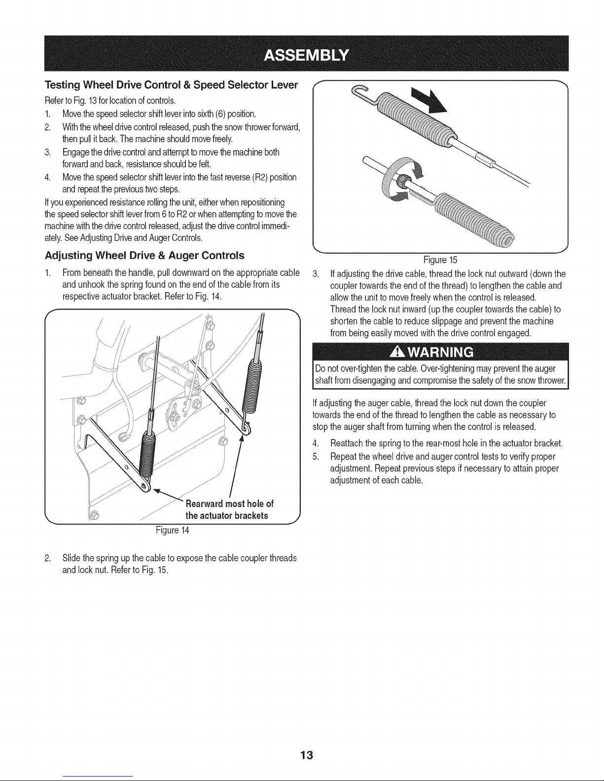
Figure15
Ifadjustingthedrivecable,threadthelock nutoutward(downthe
couplertowardstheend of thethread)tolengthenthecableand
allowthe unitto movefreelywhenthe controlisreleased.
Threadthe locknutinward(upthecouplertowardsthecable)to
shortenthecableto reduceslippageandpreventthemachine
frombeingeasilymovedwiththedrive controlengaged.
Donotover-tightenthecable.Over-tighteningmaypreventtheauger
shaftfromdisengagingandcompromisethesafetyofthe snowthrower.
b_ Rearwardmost holeof
\.. theactuator brackets .1)
Figure14
2. Slidethespringup thecableto exposethecablecouplerthreads
andlocknut. Referto Fig.15.
Ifadjustingtheaugercable,threadthe locknutdownthecoupler
towardstheendofthe threadto lengthenthecableas necessaryto
stoptheaugershaftfromturningwhenthecontrolis released.
4. Reattachthespringtothe rear-mostholeinthe actuatorbracket.
5. Repeatthewheeldriveandaugercontrolteststo verifyproper
adjustment.Repeatpreviousstepsif necessarytoattainproper
adjustmentof eachcable.
13
Page 14
"I- SpeedSelector '_
Lever
Drive 'Chute ControlTM
Control
Headli_
ChuteAssembly
WheelSteeringControl
Drift Cutters '_
Clean-outTool
Augers
\Auger
Housing
f
SkidShoes
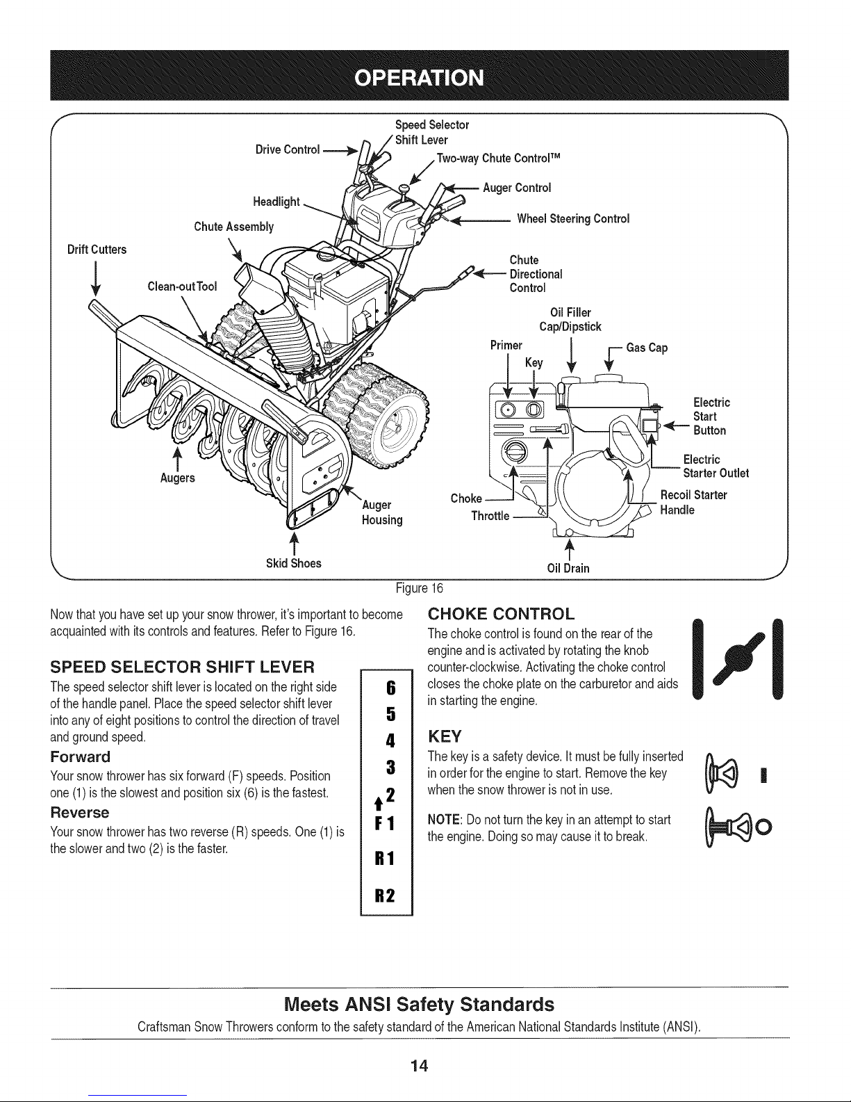
Nowthat youhavesetup yoursnowthrower,it'simportanttobecome
acquaintedwith itscontrolsandfeatures.RefertoFigure16.
SPEED SELECTOR SHIFT LEVER
Thespeedselectorshiftleveris locatedon therightside
ofthe handlepanel.Placethespeedselectorshiftlever
intoany ofeightpositionstocontrolthedirectionof travel
andgroundspeed.
Forward
Yoursnowthrowerhassixforward(F) speeds.Position
one(1)isthe slowestandpositionsix(6)isthefastest.
Reverse
Yoursnowthrowerhastwo reverse(R)speeds.One(1)is
theslowerandtwo (2) is thefaster.
6
5
4
3
t 2
F1
R1
Chute
Directional
Control
Oil Filler
Cap/Dipstick
PrimerKey
Throttle
OilDrain
Figure16
CHOKE CONTROL
Thechokecontrolisfoundon the rearofthe
engineand isactivatedbyrotatingtheknob
counter-clockwise.Activatingthechokecontrol
closesthe chokeplateon thecarburetorandaids
in startingtheengine.
KEY
Thekeyis a safetydevice.It mustbefullyinserted
in orderforthe engineto start.Removethekey
whenthe snowthroweris notinuse.
NOTE:Donotturnthekeyinan attemptto start
theengine.Doingsomaycauseit to break.
Electric
Start
Button
Electric
Starter Outlet
RecoilStarter
Handle
J
Meets ANSI Safety Standards
CraftsmanSnowThrowersconformtothe safetystandardof theAmericanNationalStandardsInstitute(ANSI).
R2
14
Page 15
ThrottleControl
GAS CAP
Unthreadthegascapto addgasolinetothefueltank.
OIL DRAIN
Engineoilcanbedrainedthroughtheoildrain.
Thethrottlecontrolis locatedonthe rearofthe engine.It regulatesthe
speedof theengineandwill shutoff theenginewhenmovedintothe
STOPposition.
PRIMER
Depressingtheprimerforcesfuel directlyintotheengine'scarburetor
toaidin cold-weatherstarting.
Engineoil levelcanbecheckedandoiladded
OIL FILL I _Tp_._-
throughtheoilfill. |
RECOIL STARTER HANDLE
Thishandleisusedto manuallystarttheengine.
ELECTRIC STARTER BUTTON
Pressingtheelectricstarterbuttonengagestheengine'selectric
starterwhenpluggedintoa 120Vpowersource.
ELECTRIC STARTER OUTLET
Requirestheuseof athree-prongoutdoorextensioncord(included)
anda 120Vpowersource/walloutlet.
AUGERS
Whenengaged,the augersrotateanddrawsnowintothe auger
housing.
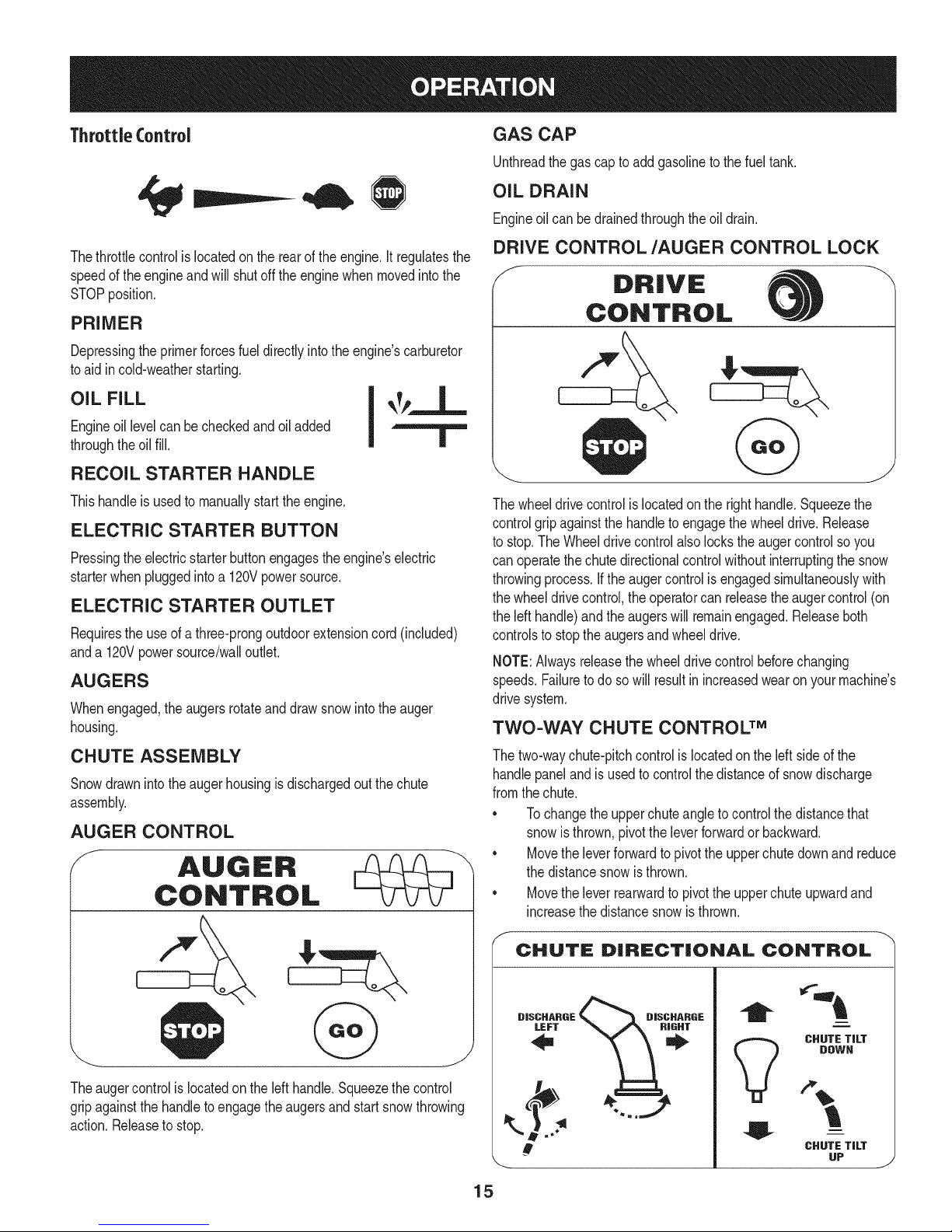
DRIVE CONTROL/AUGER CONTROL LOCK
f
DRIVE
CONTROL
Thewheeldrivecontrolis locatedonthe righthandle.Squeezethe
controlgrip againstthehandletoengagethewheeldrive.Release
to stop.TheWheeldrivecontrolalsolockstheaugercontrolsoyou
canoperatethechutedirectionalcontrolwithoutinterruptingthe snow
throwingprocess.Iftheaugercontrolis engagedsimultaneouslywith
thewheeldrivecontrol,theoperatorcanreleasetheaugercontrol(on
theleft handle)andtheaugerswill remainengaged.Releaseboth
controlsto stoptheaugersandwheeldrive.
NOTE:Alwaysreleasethewheeldrivecontrolbeforechanging
speeds.Failureto do sowillresultinincreasedwearon yourmachine's
drivesystem.
TWO-WAY CHUTE CONTROL TM
CHUTE ASSEMBLY
Snowdrawnintotheaugerhousingisdischargedout thechute
assembly.
AUGER CONTROL
f
AUGER
CONTROL
Theaugercontrolis locatedontheleft handle.Squeezethecontrol
gripagainstthehandleto engagetheaugersandstartsnowthrowing
action.Releasetostop.
Thetwo-waychute-pitchcontrolislocatedonthe left sideof the
handlepanelandisusedto controlthedistanceofsnowdischarge
fromthechute.
• Tochangetheupperchuteangletocontrolthedistancethat
snowisthrown,pivottheleverforwardor backward.
• Movetheleverforwardtopivottheupperchutedownand reduce
thedistancesnowisthrown.
• Movetheleverrearwardtopivotthe upperchuteupwardand
increasethedistancesnowisthrown.
CHUTE DiRECTiONAL CONTROL
DISCHARGE _ DISCHARGE
CHUTE TiLT
DOWN
!
CHUTE TiLT
UP
15
J
Page 16
NOTE:Toincreaseordecreasethe tensiononthetwo-waychute
control,tightenorloosenthewing knobonthe chuteassembly.
BEFORE STARTING ENGINE
CHUTE DIRECTIONAL CONTROL
Thechutedirectionalcontrolislocatedon theleftsideof thesnow
thrower.
• Tochangethedirectioninwhichsnowisthrown,crankclockwiseto
dischargetotheleftandcounterclockwiseto dischargeto theright.
SKID SHOES
Positiontheskidshoesbasedonsurfaceconditions.Adjustupward
forhard-packedsnow.Adjustdownwardwhenoperatingongravelor
crushedrocksurfaces.
WHEEL STEERING CONTROLS
Theleftandrightwheelsteeringcontrolsarelocatedonthe underside
ofthe handles.Squeezetherightcontroltoturn right;squeezetheleft
controltoturn left.
NOTE:Operatethesnowthrowerinopenareasuntilyouarefamiliar
withthesecontrols.
HEADLIGHT
Theheadlightis locatedinsideofthehandlepanel.
DRIFT CUTTERS
Thedrift cuttersaredesignedforuse indeepsnow.Theiruseis
optionalfornormalsnowconditions.Maneuverthesnowthrowerso
thatthecutterspenetrateahighstandingsnowdrifttoassistsnow
fallingintotheaugersforthrowing.
Read,understand,andfollowall instructionsand warningsonthe
machineandinthis manualbeforeoperating.
Oil
Theunitwasshippedwithoilin the engine.Checkoil levelbeforeeach
operationtoensureadequateoil inthe engine.Forfurtherinstructions,
refertotheService& Maintenancesectionofthis manual.
NOTE:Besuretochecktheengineona levelsurfacewiththeengine
stopped.
1. Removetheoilfillercap/dipstickandwipethedipstickclean.
2. Insertthecap/dipstickintotheoil fillerneck,andtightenthecap
turningclockwiseuntilcap isseated.
NOTE:Onsomeengines,athreadedscrewcapwillbe present
insteadofthe quarterturnlockingcap.Inthe instanceofa
threadedoilcap/dipstick,DONOTscrewthecap/dipstickinto
check.Checktheoil byrestingthecap/dipstickonthethreads,
butnot screwingitin.
.
Removetheoilfiller cap/dipstick.Ifthelevelis low,slowlyadd
oil (5W-30,witha minimumclassificationofSF/SG)untiloil level
registersbetweenhigh(H)andlow (L).
NOTE:Donotoverfill.Overfillingwithoil mayresultinenginesmoking,
hardstartingor sparkplugfouling.
4. Replaceandtightencap/dipstickfirmlybeforestartingengine
Gasoline
CLEAN-OUT TOOL
Thechuteclean-outtoolisconvenientlyfastenedtotherearof the
augerhousingwitha mountingclip.Shouldsnowandice become
lodgedin thechuteassemblyduringoperation,proceedas followsto
safelycleanthechuteassemblyandchuteopening:
Neveruseyourhandsto cleara cloggedchuteassembly.Shut
offengineand remainbehindhandlesuntil all movingpartshave
stoppedbeforeunclogging.
1. Releaseboththe AugerControlandtheWheeldrivecontrol.
2. Stopthe enginebyremovingthekey.
3. Removetheclean-outtoolfromtheclipwhichsecuresittothe
rearofthe augerhousing.
4. Usetheshovel-shapedendoftheclean-outtoolto dislodgeand
scoopanysnowandicewhichhasformedinandnearthechute
assembly.
5. Refastentheclean-outtooltothemountingcliponthe rearofthe
augerhousing,reinsertthekeyandstartthesnowthrower'sengine.
6. Whilestandinginthe operator'sposition(behindthesnow
thrower),engagetheaugercontrolfora fewsecondstoclearany
remainingsnowandice fromthechuteassembly.
Useextremecarewhenhandlinggasoline.Gasolineisextremely
flammableandthevaporsare explosive.Neverfuelthemachine
indoorsorwhiletheengineis hotor running.Extinguishcigarettes,
cigars,pipesandothersourcesof ignition.
Useautomotivegasoline(unleadedor lowleadedtominimizecombus-
tionchamberdeposits)witha minimumof87 octane.Gasolinewith
up to 10%ethanolor 15%MTBE(MethylTertiaryButylEther)canbe
used.Neverusean oil/gasolinemixtureordirty gasoline.Avoidgetting
dirt, dust,or waterinthe fueltank.DONOTuse E85gasoline.
• Refuelina well-ventilatedareawiththeenginestopped.Donot
smokeorallowflamesor sparksin theareawheretheengineis
refueledor wheregasolineisstored.
• Donot overfillthefueltank.After refueling,makesurethetank
capis closedproperlyandsecurely.
• Becarefulnotto spillfuelwhenrefueling.Spilledfuelorfuelvapor
mayignite.Ifanyfuelis spilled,makesuretheareais drybefore
startingthe engine.
• Avoidrepeatedor prolongedcontactwithskinorbreathingofvapor
1. Cleanaroundfuel fillbeforeremovingcaptofueltopreventdebris
fromenteringfueltank..
2. A fuellevelindicatorislocatedin thefueltank.Filltankuntilfuel
reachesthefuellevelindictor.SeeFigure10inset.Becarefulnot
tooverfill.
16
Page 17
STARTING THE ENGINE Recoil Starter
Alwayskeephandsandfeetclearofmovingparts.Donotusea
pressurizedstartingfluid.Vaporsareflammable.
NOTE:Allowtheengineto warmupfora fewminutesafterstarting.
Theenginewill notdevelopfullpoweruntilit reachesoperating
temperatures.
1. Makecertainboththe augercontrolandwheeldrivecontrolarein
thedisengaged(released)position.
2. Insertkeyintoslot.Makesureit snapsinto place.Donotattempt
toturnthekey.
NOTE:The enginecannotstartwithoutthekeyfullyinsertedintothe
ignitionswitch.
Electric Starter
Theoptionalelectricstarterisequippedwithagroundedthree-wire
powercordandplug,andis designedtooperateon 120voltAC
householdcurrent.Itmust beusedwitha properlygroundedthree-
prongreceptacleatalltimesto avoidthe possibilityof electricshock.
Followallinstructionscarefullypriorto operatingtheelectricstarter.
Determinethatyourhome'swiringis athree-wiregroundedsystem.
Aska licensedelectricianifyouarenotcertain.
If youhavea groundedthree-prongreceptacle,proceedasfollows:
1. Plugtheextensioncordinto theoutletlocatedontheengine's
surface.Plugtheotherendofextensioncordintoathree-prong
120-volt,grounded,ACoutletin awell-ventilatedarea.
2. Movethrottlecontrolto FAST(rabbit)_ position.
3. Movechoketothe CHOKEpositionI,._1 (coldenginestart).
NOTE:Ifthe engineisalreadywarm,placechokecontrolinthe
RUNpositioninsteadof CHOKEIJl position.
4. Pushprimerthreetimes(3x),makingsureto coverventholein
primerbulbwhen pushing.Ifengineiswarm,pushprimeronly
once.Alwayscoverventholewhenpushing.Coolweathermay
requireprimingtobe repeated.
5. Pushstarterbuttontostart engine.Oncetheenginestarts,im-
mediatelyreleasestarterbutton.Electricstarteris equippedwith
thermaloverloadprotection;systemwilltemporarilyshut-downto
allowstartertocool ifelectricstarterbecomesoverloaded.
Toprolongstarterlife,useshortstartingcycles(5 secondsmaximum
thenwaitoneminute).
6. Astheenginewarms,slowlyrotatethe chokecontroltothe RUN
position.Ifthe enginefalters,restartengineandrunwithchoke
athalf-chokepositionfor a shortperiodoftime,andthenslowly
rotatethechokeintothe RUNposition.
7. Afterengineisrunning,disconnectpowercordfromelectric
starter.Whendisconnecting,alwaysunplugtheendat thewall
outletbeforeunpluggingtheoppositeendfromtheengine.
Donot pullthestarterhandlewhile theenginerunning.
1. Movethrottlecontrolto FAST(rabbit)_ position.
2. Movechoketothe CHOKEIJl position'_'(coldenginestart).If
engineiswarm,placechokeinthe RUNposition.
3. Pushprimerthreetimes,makingsuretocoverventholewhen
pushing.If engineiswarm,pushprimeronlyonce.Alwayscover
ventholewhenpushing.Coolweathermayrequireprimingto be
repeated.
4. Pullgentlyonthestarterhandleuntilit beginsto resist,thenpull
quicklyandforcefullytoovercomethe compression.Engineshould
start.Donot releasethehandleandallowitto snapback.Return
ropeSLOWLYto originalposition.Ifrequired,repeatthisstep.
5. Asthe enginewarms,slowlyrotatethe chokecontroltothe RUN
position.Ifthe enginefalters,restartengineandrunwithchoke
at half-chokepositionfora shortperiodof time,andthenslowly
rotatethechokeintotheRUNposition.
Toavoidunsupervisedengineoperation,neverleavethemachine
unattendedwiththe enginerunning.Turntheengineoff afteruseand
removekey.
STOPPING THE ENGINE
Afteryouhavefinishedsnow-throwing,runenginefor a fewminutes
beforestoppingto helpdry off anymoistureon the engine.
1. Movethrottlecontrolto STOPI_ position.
inc. Backfireoren( occur.
2. Removethekey.Removingthekeywillreducethepossibilityof
unauthorizedstartingof theenginewhileequipmentisnotinuse.
Keepthekeyinasafeplace.Theenginecannotstartwithoutthekey.
3. Wipeallsnowand moisturefromtheareaaroundtheengineas
wellas theareain andaroundthe wheeldrivecontrolandauger
control.Also,engageand releasebothcontrolsseveraltimes.
TO ENGAGE WHEEL DRIVE
1. Withthethrottlecontrolinthe Fast(rabbit)_ position,move
speedselector leverintooneofthe sixforward(F)positionsor
two reverse(R)positions.Selecta speedappropriateforthe
snowconditionsanda paceyou'recomfortablewith.
NOTE: WhenselectingaDriveSpeed,usethe slowerspeeds
untilyouarecomfortableandfamiliarwiththe operationofthe
snowthrower.
2. Squeezethe drivecontrolagainstthehandleandthesnow
throwerwillmove.Releaseit anddrivemotionwillstop.
NOTE:NEVERrepositionthespeedselectorlever(changespeedsor
directionoftravel)withoutfirstreleasingthe drivecontrolandbringing
thesnowthrowertoa completestop.Doingso willresultin premature
wearto thesnowthrower'sdrivesystem.
17
Page 18
TO ENGAGE AUGER
1. Toengagetheaugerandstartthrowingsnow,squeezetheauger
controlagainstthelefthandle.Releaseto stoptheaugers.
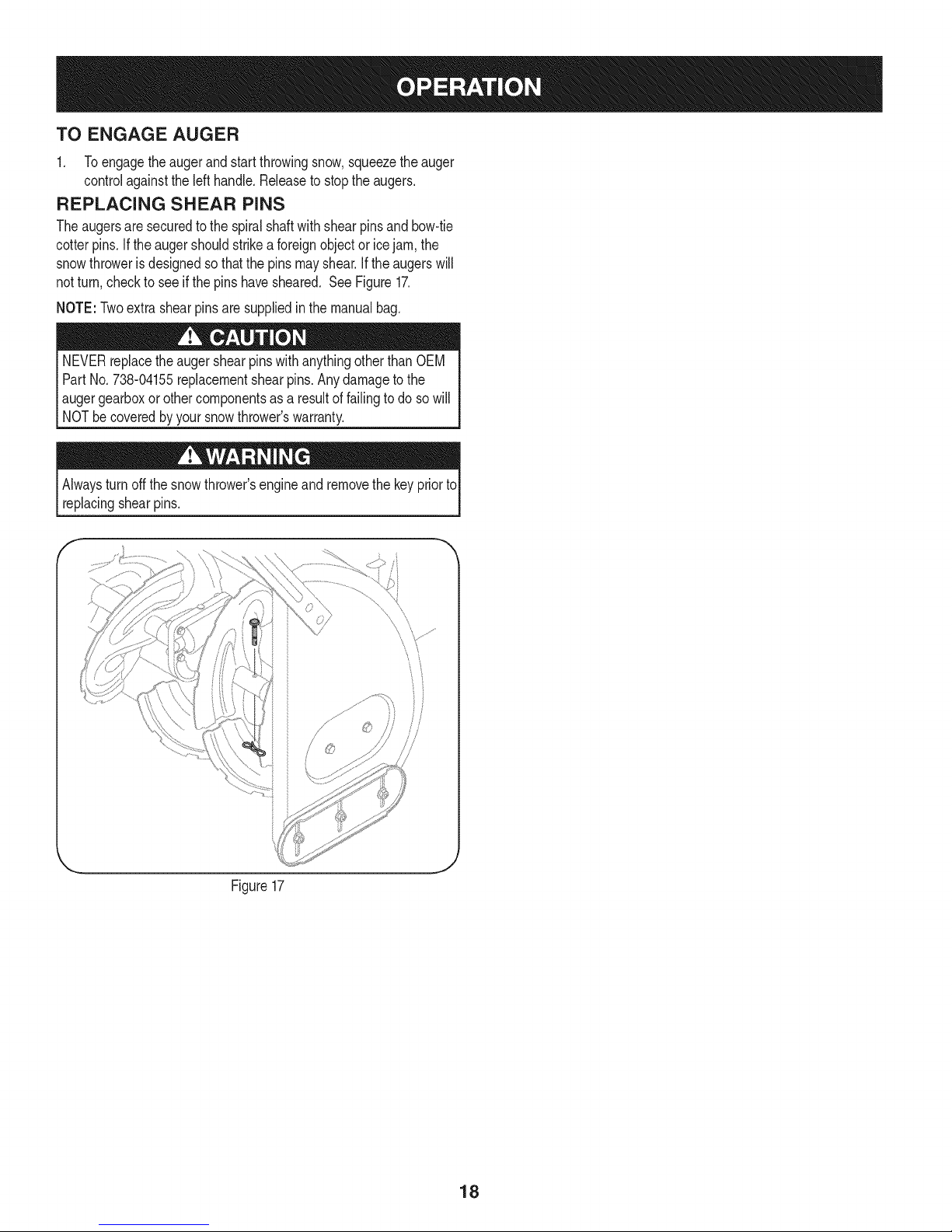
REPLACING SHEAR PINS
Theaugersaresecuredtothe spiralshaftwithshearpinsandbow-tie
cotterpins.Ifthe augershouldstrikea foreignobjector icejam,the
snowthrowerisdesignedsothatthe pinsmayshear.If theaugerswill
notturn,checkto seeifthe pinshavesheared.SeeFigure17.
NOTE:Twoextrashearpinsare suppliedinthemanualbag.
NEVERreplacetheaugershearpinswithanythingotherthanOEM
PartNo.738-04155replacementshearpins.Anydamagetothe
Iaugergearboxor othercomponentsas,a resultoffailingtodo so will
[NOTbe coveredbyyoursnowthrowers warranty.
Alwaysturnoff thesnowthrower'sengineand removethekeypriorto
replacingshearpins.
f-
Figure17
18
Page 19
MAINTENANCE SCHEDULE
Beforeperforminganytypeofmaintenance/service,disengageall
controlsandstoptheengine.Waituntilallmovingpartshavecometo a
completestop.Removethekeytopreventunintendedstarting.Always
wearsafetyglassesduringoperationorwhileperforminganyadjustments
orrepairs.
EachUse
1st5 - 8 hours
25 hours
50 hours
Annuallyor100hours
1. Engineoillevel
2. Looseormissinghardware
3. Unitandengine.
1. Engineoil
1. Engineoi11-
2. Controllinkagesand pivots
1. Engineoil
1. Sparkplug
1. Check
2. Tightenor replace
3. Clean
1. Change
1. Change
2. Lubewithlightoil
1. Change
1. Cleanand re-gap,orelse replace
withnewplug.
BeforeStorage 1. Fuelsystem
1. Runengineuntilit stopsfromlackof
fueloradda gasolineadditivetothe
gasin thetank.
Underheavyloador inhightemperatures
Followthemaintenanceschedulegivenbelow.Thischartdescribes
serviceguidelinesonly.UsetheServiceLogcolumnto keeptrackof
completedmaintenancetasks.To locate the nearest Sears Service
Centeror toscheduleservice,simplycontactSears at
1-800-4-MY-HOME®.
= =
ENGINE MAINTENANCE
Checking Engine Oil
Beforelubricating,repairing,or inspecting,disengageallcontrolsand
stopengine.Waituntilallmovingpartshavecometoa completestop.
Removethekeyto preventunintendedfiringoftheengine.
NOTE: Checktheoil levelbeforeeachuseto besurecorrectoil level
ismaintained.
Whenaddingoilto theengine,referto viscositychart below.Engineoil
capacityisapproximately37 ounces.Donot over-fill.Usea4-stroke,
oran equivalenthighdetergent,premiumqualitymotoroilcertified
tomeetorexceedU.S.automobilemanufacturer'srequirementsfor
serviceclassificationSG,SR MotoroilsclassifiedSG,SFwill show
thisdesignationonthe container.
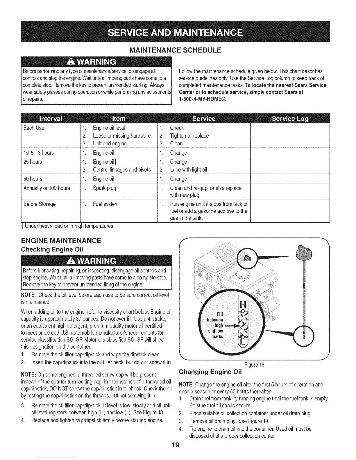
1. Removetheoilfillercap/dipstickandwipethedipstickclean.
2. Insertthe cap/dipstickintotheoil fillerneck,butdo not screwit in.
NOTE:On someengines,athreadedscrewcap willbepresent
insteadofthequarterturn lockingcap.Inthe instanceof a threadedoil
cap/dipstick,DONOTscrewthecap/dipstickin tocheck.Checktheoil
byrestingthe cap/dipstickonthe threads,butnotscrewingitin.
3. Removetheoilfillercap/dipstick,iflevelislow,slowlyaddoiluntil
oil levelregistersbetweenhigh(H)andlow(L).SeeFigure18.
4. Replaceandtightencap/dipstickfirmlybeforestartingengine.
J
Figure18
Changing Engine Oil
NOTE:Changetheengineoil afterthefirst5 hoursofoperationand
oncea seasonorevery50 hoursthereafter.
1. Drainfuelfromtankbyrunningengineuntilthefuel tankisempty.
Besurefuel fillcapis secure.
2. Placesuitableoilcollectioncontainerunderoil drainplug.
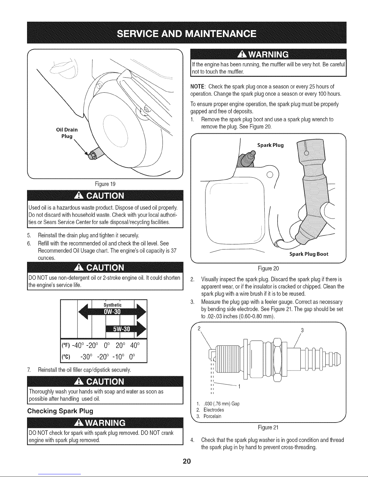
3. Removeoil drainplug.SeeFigure19.
4. Tipengineto drainoil intothe container.Usedoil mustbe
disposedofat a propercollectioncenter.
19
Page 20
f
Oil Drain
Plug
Figure19
Usedoilisa hazardouswasteproduct.Disposeof usedoilproperly.
Donotdiscardwith householdwaste.Checkwithyourlocalauthori-
tiesor SearsServiceCenterfor safedisposal/recyclingfacilities.
ifthe enginehasbeenrunning,themufflerwillbeveryhot.Becareful
notto touchthemuffler.
NOTE: Checkthesparkplugonce a seasonorevery25hoursof
operation.Changethe sparkplugoncea seasonorevery100hours.
Toensureproperengineoperation,the sparkplugmustbeproperly
gappedandfreeof deposits.
1. Removethesparkplugbootand useasparkplugwrenchto
removetheplug.SeeFigure20.
Spark Plug
.
Reinstallthedrainplugandtightenit securely.
6.
Refillwiththerecommendedoil andchecktheoil level.See
RecommendedOil Usage chart. The engine's oilcapacity is 37
ounces.
DONOTuse non-detergentoilor 2-strokeengineoil.Itcouldshorten
theengine'sservicelife.
(°F}=40o =20o 0o 200 400
(°c) -30° -20° -10° 0°
7. Reinstalltheoilfillercap/dipsticksecurely.
Thoroughlywashyour handswithsoapandwaterassoonas
possibleafterhandling usedoil.
Checking Spark Plug
DONOTcheckforsparkwithsparkplugremoved.DO NOTcrank
enginewithsparkplugremoved.
Figure20
2. Visuallyinspectthe sparkplug.Discardthe sparkplugif thereis
apparentwear,orif theinsulatoriscrackedorchipped.Cleanthe
sparkplugwithawirebrushifit istobe reused.
3. Measurethepluggapwitha feelergauge.Correctasnecessary
bybendingsideelectrode.SeeFigure21.Thegapshouldbeset
to .02-.03inches(0.60-0.80ram).
,'2 3
1..030 (.76 mm) Gap
2. Electrodes
k"_i Porcelain
Figure21
4. Checkthatthesparkplugwasheris ingoodconditionandthread
thesparkpluginby handtopreventcross-threading.
2O
Page 21
5. Afterthe sparkplugisseated,tightenwithasparkplugwrenchto
compressthewasher.
NOTE:Wheninstallinga newsparkplug,tighten1/2-turnafterthe
sparkplugseatsto compressthe washer.Whenreinstallinga used
sparkplug,tighten1/8-to 1/4-turnafterthesparkplugseatsto
compressthewasher.
hotandcan ine.
CARBURETOR ADJUSTMENT
Thecarburetoris notuseradjustable.ContactSearsParts& Repairfor
adjustment.
LUBRICATION
Drive and Shifting Mechanism
Atleastoncea seasonor afterevery25 hoursofoperation,remove
rearcover.Lubricateall chains,sprockets,gears,bearings,shafts,and
theshiftingmechanism.Useengineoilora spraylubricant.Referto
Figure22.
NOTE:Beforetippingtheunitonthe fronthousing,runthefueltank
emptyso fueldoes notleak outof thefuelcap.
1. Carefullypivotthesnowthrowerupandforwardsothat it restson
theaugerhousing.
2. Removetheframecoverfromtheundersideof thesnowthrower
byremovingtheself-tappingscrewswhichsecureit. Referto
Figure27.
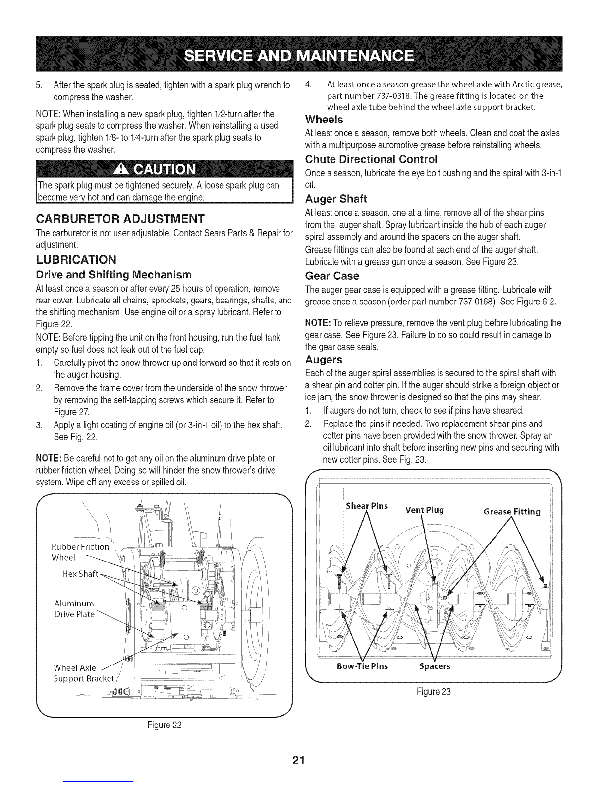
3. Applya lightcoatingof engineoil (or3-in-1oil) tothe hexshaft.
SeeFig.22.
NOTE:Becarefulnottoget anyoilon thealuminumdrive plateor
rubberfrictionwheel.Doingsowill hinderthesnowthrower'sdrive
system.Wipeoff anyexcessorspilledoil.
4. At least once a season grease the wheel axle with Arctic grease,
part number 737-0318. The grease fitting is located on the
wheel axle tube behind the wheel axle support bracket.
Wheels
At leastoncea season,removebothwheels.Cleanandcoattheaxles
witha multipurposeautomotivegreasebeforereinstallingwheels.
Chute Directional Control
Onceaseason,lubricatethe eyebolt bushingandthe spiralwith3-in-1
oil.
Auger Shaft
At leastoncea season,oneat a time,removeallof theshearpins
fromthe augershaft.Spraylubricantinsidethehubof eachauger
spiralassemblyandaroundthe spacersonthe augershaft.
Greasefittingscan alsobe foundateach endofthe augershaft.
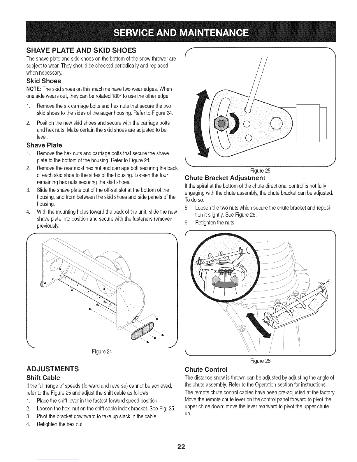
Lubricatewitha greasegunoncea season.SeeFigure23.
Gear Case
Theaugergearcaseis equippedwitha greasefitting.Lubricatewith
greaseoncea season(orderpartnumber737-0168).SeeFigure6-2.
NOTE:Torelievepressure,removetheventplugbeforelubricatingthe
gearcase.See Figure23. Failuretodoso couldresultindamageto
thegearcaseseals.
Augers
Eachoftheaugerspiralassembliesis securedtothe spiralshaftwith
a shearpinandcotter pin.If the augershouldstrikeaforeignobjector
icejam,the snowthrowerisdesignedsothatthe pinsmayshear.
1. Ifaugersdonot turn,checkto seeif pinshavesheared.
2. Replacethepinsif needed.Tworeplacementshearpinsand
cotterpins havebeenprovidedwiththe snowthrower.Sprayan
oil lubricantintoshaft beforeinsertingnewpinsand securingwith
newcotter pins.See Fig.23.
i • i I ii
i Shear Pins ii:i
" Vent Plug Grease Fitting
Aluminum
Drive
Wheel Axle
Support Bracket
Figure22
/ .............
Bow=Tie Pins Spacers
Figure23
21
Page 22
SHAVE PLATE AND SKiD SHOES
Theshaveplateand skidshoesonthebottomofthesnowthrowerare
subjectto wear.Theyshouldbecheckedperiodicallyandreplaced
whennecessary.
Skid Shoes
NOTE:Theskidshoesonthismachinehavetwowearedges.When
onesidewearsout, theycan be rotated1800to usethe otheredge.
1. Removethesix carriageboltsandhexnutsthatsecurethetwo
skidshoestothe sidesofthe augerhousing.RefertoFigure24.
2. Positionthenew skidshoesandsecurewiththecarriagebolts
andhexnuts.Makecertaintheskidshoesare adjustedtobe
level.
Shave Plate
1. Removethehexnutsandcarriageboltsthatsecuretheshave
plateto thebottomofthe housing.Referto Figure24.
2. Removetherearmosthexnutand carriageboltsecuringtheback
ofeachskidshoeto thesidesof thehousing.Loosenthefour
remaininghexnutssecuringthe skidshoes.
3. Slidetheshaveplateoutof theoff-setslotat thebottomofthe
housing,andfrombetweenthe skidshoesandsidepanelsofthe
housing.
4. Withthemountingholestowardthebackof theunit,slidethenew
shaveplateinto positionandsecurewiththe fastenersremoved
previously.
f
k
J
Figure25
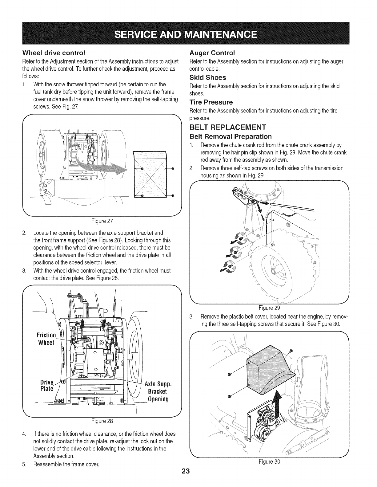
Chute Bracket Adjustment
Ifthespiralatthe bottomof thechutedirectionalcontrolis notfully
engagingwiththechuteassembly,the chutebracketcanbeadjusted.
Todo so:
5. Loosenthetwo nutswhichsecurethechutebracketandreposi-
tionit slightly.SeeFigure26.
6. Retightenthenuts.
Figure24
ADJUSTMENTS
Shift Cable
If thefull rangeofspeeds(forwardandreverse)cannotbe achieved,
referto theFigure25 andadjusttheshiftcableas follows:
1. Placethe shiftleverin thefastestforwardspeedposition.
2. Loosenthehex nutontheshiftcableindexbracket.SeeFig.25.
3. Pivotthebracketdownwardtotakeupslack inthecable.
4. Retightenthehexnut.
0
Figure26
Chute Control
Thedistancesnowisthrowncanbe adjustedbyadjustingtheangleof
thechuteassembly.Referto theOperationsectionforinstructions.
Theremotechutecontrolcableshavebeenpre-adjustedatthefactory.
Movethe remotechuteleveronthecontrolpanelforwardtopivotthe
upperchutedown;movetheleverrearwardtopivottheupperchute
up.
22
Page 23
Wheel drive control
Refertothe Adjustmentsectionofthe Assemblyinstructionsto adjust
thewheeldrivecontrol.Tofurtherchecktheadjustment,proceedas
follows:
1. Withthe snowthrowertippedforward(becertainto runthe
fueltankdry beforetippingtheunitforward),removetheframe
coverunderneaththesnowthrowerby removingtheself-tapping
screws.SeeFig.27.
J
Figure27
Auger Control
RefertotheAssemblysectionforinstructionson adjustingtheauger
controlcable.
Skid Shoes
RefertotheAssemblysectionforinstructionson adjustingtheskid
shoes.
Tire Pressure
RefertotheAssemblysectionforinstructionson adjustingthetire
pressure.
BELT REPLACEMENT
Belt Removal Preparation
1. Removethechutecrankrodfromthechutecrankassemblyby
removingthehairpinclip shownin Fig.29.Movethechutecrank
rodawayfromtheassemblyas shown.
Removethreeself-tapscrewson bothsidesof thetransmission
housingas shownin Fig.29.
2. Locatetheopeningbetweentheaxlesupportbracketand
thefrontframesupport(SeeFigure28). Lookingthroughthis
opening,withthe wheeldrivecontrolreleased,theremustbe
clearancebetweenthefrictionwheelandthedriveplateinall
positionsofthespeedselectorlever.
3. Withthewheeldrivecontrolengaged,thefrictionwheelmust
contactthedrive plate.SeeFigure28.
Drive -Axle Supp.
Plate Bracket
Opening
Figure29
3. Removethe plasticbeltcover,locatedneartheengine,byremov-
ing thethreeself-tappingscrewsthatsecureit.See Figure30.
f
Figure28
4. Ifthereisnofrictionwheelclearance,or thefrictionwheeldoes
notsolidlycontactthe driveplate,re-adjustthelocknuton the
lowerendof thedrive cablefollowingtheinstructionsin the
Assemblysection.
5. Reassemblethe framecover.
23
Page 24
.
Loosentheboltshownin Figure31securingthebeltkeeper
bracketandremovetheotherbolt.Pushthebeltkeeperand
bracketupoff the enginepulley.
Loosen
\
\
Figure31
Auger Belt Replacement
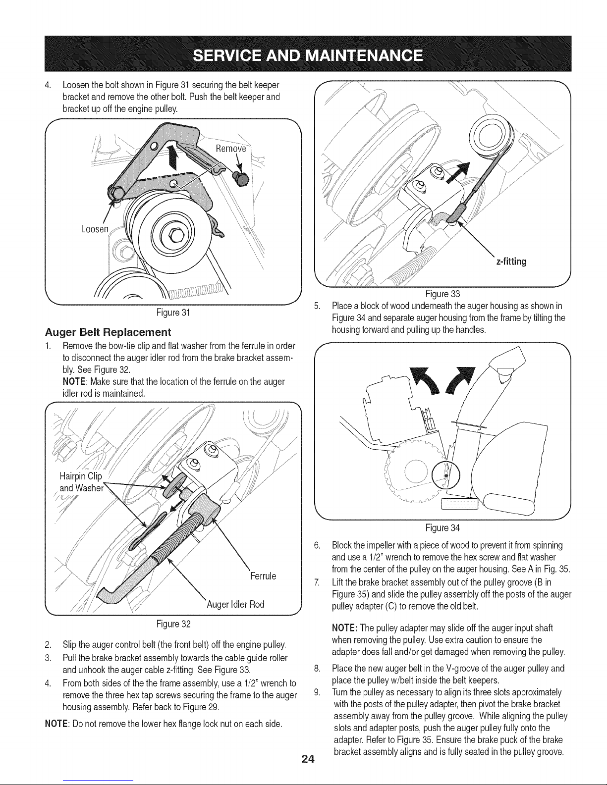
1. Removethebow-tieclipandflatwasherfromtheferrulein order
todisconnecttheaugeridlerrodfromthebrakebracketassem-
bly.SeeFigure32.
NOTE:Makesurethatthelocationof theferruleon theauger
idlerrodismaintained.
HairpinClip
Ferrule
AugerIdlerRod
z-fitting
J
Figure33
Placeablockof woodunderneaththeaugerhousingas shownin
Figure34 andseparateaugerhousingfromtheframebytiltingthe
housingforwardandpullingupthehandles.
Figure34
6. Blocktheimpellerwithapieceof woodtopreventit fromspinning
andusea 1/2"wrenchtoremovethe hexscrewandflatwasher
fromthecenterofthepulleyontheaugerhousing.SeeAinFig.35.
7. Liftthebrakebracketassemblyoutofthe pulleygroove(B in
Figure35)andslide thepulleyassemblyoff the postsof theauger
pulleyadapter(C) to removetheoldbelt.
Figure32
2. Sliptheaugercontrolbelt (thefrontbelt) offtheenginepulley.
3. Pullthebrakebracketassemblytowardsthecableguideroller
andunhooktheaugercablez-fitting.SeeFigure33.
4. Frombothsidesof thethe frameassembly,usea1/2"wrenchto
removethethreehextapscrewssecuringthe frametothe auger
housingassembly.Referbackto Figure29.
NOTE:Do notremovethelowerhexflangelocknuton eachside.
24
NOTE:Thepulleyadaptermayslideoff the augerinputshaft
whenremovingthepulley.Useextracautionto ensurethe
adapterdoesfalland/or getdamagedwhen removingthepulley.
.
Placethenewaugerbeltin theV-grooveof theaugerpulleyand
placethepulleyw/belt insidethebeltkeepers.
9.
Turnthepulleyasnecessarytoalignitsthreeslotsapproximately
withthepostsofthepulleyadapter,thenpivotthebrakebracket
assemblyawayfromthepulleygroove. Whilealigningthe pulley
slotsandadapterposts,pushtheaugerpulleyfullyontothe
adapter.RefertoFigure35.Ensurethebrakepuckofthebrake
bracketassemblyalignsandis fullyseatedin thepulleygroove.
Page 25
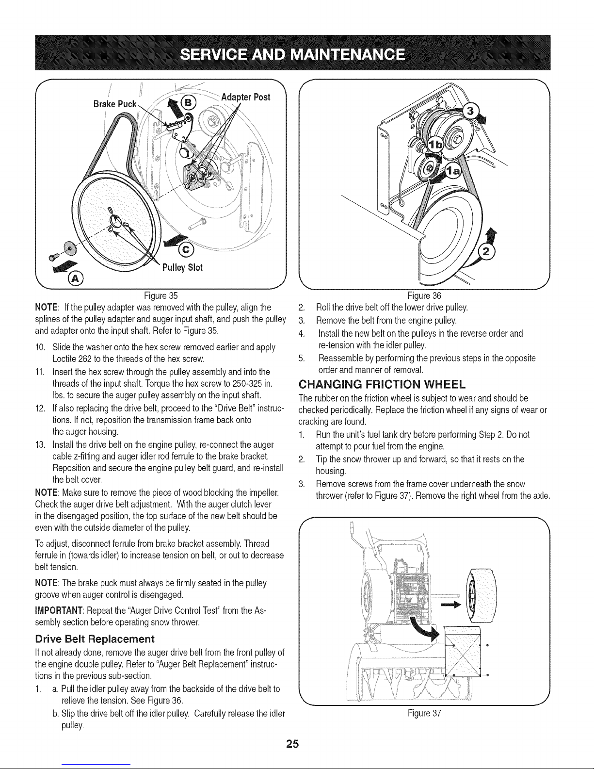
Brake
!
pterPost
%
J
Figure35
NOTE: If the pulleyadapterwasremovedwiththe pulley,alignthe
splinesofthe pulleyadapterandaugerinputshaft,andpushthepulley
andadapterontotheinputshaft.Referto Figure35.
10. Slidethewasherontothehexscrewremovedearlierandapply
Loctite262to thethreadsofthehexscrew.
11. Insertthehexscrewthroughthepulleyassemblyandintothe
threadsofthe inputshaft.Torquethehex screwto250-325in.
Ibs.to securetheaugerpulleyassemblyon the inputshaft.
12. Ifalsoreplacingthedrivebelt,proceedtothe"DriveBelt"instruc-
tions.If not,repositionthetransmissionframebackonto
theaugerhousing.
13. Installthedrivebelton theenginepulley,re-connecttheauger
cablez-fittingandaugeridler rodferruletothe brakebracket.
Repositionand securetheenginepulleybeltguard,and re-install
thebeltcover.
NOTE:Makesureto removethepieceof woodblockingthe impeller.
Checktheaugerdrivebeltadjustment.Withthe augerclutchlever
inthedisengagedposition,thetopsurfaceofthenewbeltshouldbe
evenwiththeoutsidediameterofthe pulley.
Toadjust,disconnectferrulefrombrakebracketassembly.Thread
ferrulein(towardsidler)toincreasetensiononbelt,orouttodecrease
belttension.
J
Figure36
2. Rollthedrivebeltoff thelowerdrivepulley.
3. Removethe beltfromthe enginepulley.
4. Installthe newbelton thepulleysinthe reverseorderand
re-tensionwiththeidlerpulley.
5. Reassemblebyperformingthe previousstepsintheopposite
orderand mannerofremoval.
CHANGING FRICTION WHEEL
Therubberonthe frictionwheelissubjecttowearandshouldbe
checkedperiodically.Replacethefrictionwheelifanysignsofwearor
crackingarefound.
1. Runthe unit'sfuel tankdry beforeperformingStep2. Donot
attempttopourfuel fromtheengine.
2. Tipthe snowthrowerupand forward,sothat it restsonthe
housing.
3. Removescrewsfromtheframecoverunderneaththesnow
thrower(referto Figure37).Removetherightwheelfromtheaxle.
NOTE:Thebrakepuckmustalwaysbefirmly seatedinthepulley
groovewhenaugercontrolisdisengaged.
IMPORTANT:Repeatthe"AugerDriveControlTest"fromthe As-
semblysectionbeforeoperatingsnowthrower.
Drive Belt Replacement
If notalreadydone,removetheaugerdrivebelt fromthefrontpulleyof
theenginedoublepulley.Referto "AugerBeltReplacement"instruc-
tionsintheprevioussub-section.
1. a.Pullthe idlerpulleyawayfromthe backsideofthedrivebeltto
relievethetension.SeeFigure36.
b.Slipthe drivebelt offtheidlerpulley.Carefullyreleasetheidler
pulley.
e
Figure37
25
Page 26

.
Usinga 3/4"wrench,holdthehexshaftandremovethehex
screwandbellevillewasherand bearingfromleft sideofthe
frame.Referto Figure38.
f
RemoveHexScrew
BellevilleWasher
l,
Figure38
.
Holdingthefrictionwheelassembly,slidethe hexshaftoutof
thefrictionwheelassemblyandthe rightsideof theframe.The
spacerontheleft sideofthe hexshaftwillfall andthesprocket
shouldremainhanginglosein the chain.
.
Liftthefrictionwheelassemblyoutbetweenthe axleshaftand
thedriveshaftassemblies.
7.
Removefourscrewssecuringthe frictionwheeltothe hub
assembly(referto Figure39).Discardoldfrictionwheel.
FrictionWheelAss'y.
/
SlideHex
ShaftOut
RightSide
f
!!Si¸i¸i¸;i!!¸i¸:¸¸i¸¸i¸!_¸¸_!¸¸i¸¸¸¸¸¸¸¸¸¸¸¸¸'¸¸¸"i!i_i_!!!i!i;i!iiiiii!iiiii
f
_,,, J
8. Reassemblethe newfrictionwheelontothehubassembly,
tighteningthe fourscrewsin rotationandwithequalforce.It is
importanttoassemblethefrictionwheelsymmetricallyforproper
functioning.
9. Repositionthefrictionwheelassemblyin the snowthrowerframe.
Insertthe pinfromthespeedselectorarmassemblyintothe
frictionwheelassemblyandholdassemblyinposition.Referto
Figure40.
_L
¢,
Figure39
0
Figure40
10. Slidethehexshaftthroughtherightsideof theframetowardthe
Idt sideandthroughthefrictionwheelassembly.
11. Aftermakingcertainthatthechainison boththelargeandthe
smallsprocket,alignthehexshaftwiththehexhubofthesmall
sprocket,andslidethe shaftthroughthesprocket.
NOTE:Ifthe sprocketfellfromthesnowthrowerwhile removing
thehex shaft,placethe sprocketonthechain.Realignthe
sprocketonthechainwiththehexhubfacingtherightsideof
unit.Positionthe hexhubof thesprockettowardthefrictionwheel
whenslidingthesprocketonto thehexshaft.
12. Slidethespacerontotheendofthehexshaft.
Note:The spaceristo be placedonthe hexshaftbetweenthe
sprocketandbearingpreviouslyremovedonthe leftsideofthe
frame.
13. Alignthebearingonthe rightendof thehexshaftwiththehole
intherightsideof theframe,thenpushthehexshafttotheleft
intopositioninthe frame.
14. Slidethebearingontotheleftendofthehexshaftandpressinto
theholeon theleft sidethe frame.
15. Placethebellevillewasher(roundedside towardhead)ontothe
hexscrewremovedearlier,andinsertthescrewintothethreaded
holeofthe hexshaft.
16. Graduallytightenthe hexscrewtofullyseatthe bearingsineach
sideof theframeandto securethehex shaft.
17. Positiontheframecoveron the bottomoftheframeand secure
withtheself-tappingscrews.Pivotthesnowthrowerdownto it
normaloperatingposition.
iMPORTANT:Repeatthedrivecontroltestfromthe Assemblysection
ofthis manualbeforeoperatingthe snowthrower.
26
Page 27

Ifthesnowthrowerwillnotbeusedfor30daysorlonger,orifitistheendofthesnowseasonwhenthelastpossibilityofsnowisgone,the
equipmentneedstobestoredproperly.Followstorageinstructionsbelowtoensuretopperformancefromthesnowthrowerformanymoreyears.
PREPARING ENGINE
Enginesstoredover30daysneedtobedrainedoffueltoprevent
deteriorationandgumfromforminginfuelsystemoronessential
carburetorparts.If thegasolineinyourenginedeterioratesduring
storage,youmayneedto havethecarburetor,andotherfuelsystem
components,servicedorreplaced.
1. Removeall fuelfromtankbyrunningengineuntilitstops.Donot
attempttopourfuel fromtheengine.
2. Changetheengineoil.
3. Removesparkplugandpourapproximately1oz.(30 rnl)ofclean
engineoil intothe cylinder.Pullthe recoilstarterseveraltimesto
distributetheoil,and reinstallthesparkplug.
4. Cleandebrisfromaroundengine,andunder,around,andbehind
muffler.Applya lightfilmofoilon anyareasthatare susceptible
torust.
• Storeina clean,dry andwellventilatedareaawayfromanyap-
pliancethatoperateswithaflameor pilotlight,suchasa furnace,
waterheater,or clothesdryer.Avoidanyareawitha spark
producingelectricmotor,or wherepowertoolsareoperated.
Neverstoresnowthrowerwithfuel intank indoorsorinpoorlyventi-
latedareas,wherefuelfumesmayreachanopenflame,sparkorpilol
lightas ona furnace,waterheater,clothesdryer orgasappliance.
PREPARING SNOW THROWER
Whenstoringthe snowthrowerin anunventilatedormetalstor-
age shed,careshouldbetakentorustprooftheequipment.Using
a lightoilor silicone,coattheequipment,especiallyanychains,
springs,bearingsandcables.
• Removealldirt fromexteriorofengineandequipment.
• Followlubricationrecommendations.
• Storeequipmentin a clean,dryarea.
• If possible,avoidstorageareaswithhighhumidity.
• Keepthe enginelevelin storage.Tiltingcancausefuel oroil
leakage.
27
Page 28

Enginefailstostart
Enginerunningerratically/
inconsistentRPM(huntingor
surging)
Excessivevibration
Lossofpower
Unitfailstopropelitself
Unitfailstodischargesnow
1. ChokecontrolnotinCHOKEposition.
2. Sparkplugwire disconnected.
3. Faultysparkplug.
4. Fueltankemptyor stalefuel.
5. Enginenotprimed.
6. Keynot inserted.
7. Extensioncordnotconnected(when
usingelectricstartbutton,on modelsso
equipped).
1. EnginerunningonCHOKE.
2. Stalefuel.
3. Waterordirt infuelsystem.
4. Over-governedengine.
1. Loosepartsor damagedauger.
1. Sparkplugwire loose.
2. Gascap ventholeplugged.
1. Drivecableinneedof adjustment.
2. Drivebeltlooseor damaged.
3. Wornfrictionwheel.
1. Chuteassemblyclogged.
2. Foreignobjectlodgedin auger.
3. Augercablein needof adjustment.
4. Augerbeltlooseordamaged.
5. Shearpin(s)sheared.
1. Movechokecontrolto CHOKEposition.
2. Connectwireto sparkplug.
3. Clean,adjustgap,or replace.
4. Filltankwith clean,freshgasoline.
5. PrimeengineasinstructedintheOperationSection.
6. Insertkeyfully intothe switch.
7. Connectoneendof theextensioncordto theelectric
starteroutletandthe otherendto a three-prong
120-volt,grounded,ACoutlet.
1. Movechokecontrolto RUNposition.
2. Filltankwith clean,freshgasoline.
3. Drainfueltankby runningengineuntilitstops.Refill
withfreshfuel.
4. ContactyourSearsParts& RepairCenter.
1. Stopengineimmediatelyand disconnectsparkplug
wire.Tightenall boltsand nuts.Ifvibrationcontinues,
haveunit servicedbya SearsParts&RepairCenter.
1. Connectandtightensparkplugwire.
2. Removeiceand snowfromgascap. Becertainvent
holeisclear.
1. Adjustdrivecontrolcable.Referto Serviceand
Maintenancesection.
2. Replacedrivebelt.Referto Serviceand Mainte-
nancesection.
3. Changefrictionwheelorcontactyour SearsParts&
RepairCenter.
1. Stopengineimmediatelyand disconnectsparkplug
wire.Cleanchuteassemblyandinsideofauger
housingwithclean-outtoolor a stick.
2. Stopengineimmediatelyand disconnectsparkplug
wire.Removeobjectfromaugerwith clean-outtool
ora stick.
3. Adjustaugercontrolcable.RefertoAssembly
section.
4. Replaceaugerbelt.RefertoServiceand Mainte-
nancesection.
5. Replacewith newshearpin(s).
Chutefailstoeasilyrotate180 1. Disassemblechutecontroland reassembleas
1. Chuteassembledincorrectly.
degrees directedintheAssemblysection.
NEED HORE HELP?
Yot,Fttfind. th_ answer a!ld mo_e on ma_age_y_ifeocom _ for free]
Find this and att your other product manua[s ontine.
Get answers from our team of home experts.
Get a personalized maintenance p[an for your home.
Find information and tools to he[p with home projects.
managemylife
b_e'_g_t_/_eyeu by Sea_s
27
Page 29

Craftsman Snow Thrower IViodel 247.88848
74
47
_15
21 /
\ 21
24
7O 25
\ 61
69
7O
\ 24
23
11
10
22
32
44
28
Page 30

Craftsman Snow Thrower IViodel 247.88848
D = 0
05244B Housing,Bearing
2. 784-0315A Housing,Bearing
3. 918-04514 GearBoxAssembly,Auger
4. 918-0281A BracketAssy,AugerBrake
5. 684-0090B-0637 Impellar,16"
6. 684-04224-0691 Housing,Auger- 45"
7. 684-04151-4028 SpiralAssy,LH
8. 684-04152-4028
9. 710-1245B
10. 710-0389
11. 710-0451
12. 710-0347
13. 710-0376
14. 710-04484
SpiralAssy,RH
Screw,5/16-24x .875
Bolt,Carriage,3/8-16x .750
Screw,Carriage,5/16-18x .75
Screw,HexCap,3/8-16x 1.75
Screw,HexCap,5/16-18x 1.00
Screw,5/16-18x .750
15. J 926-04012 J Nut,Push
16. 929-0071A ExtensionCord, 110V
17. 710-3168 Bolt,Carriage,3/8-16x 1.0
18. 710-04606A Screw,5/16-18x.4300
19. 911-0677 Ferrule
20. 917-0299 Gear,Worm,DblThread
21. 712-04063 Nut,FlngeLk,5/16-18
22. 712-04065 Nut,FigLk,3/8-16
23. 941-0217 Sleeve
24. 936-0291 Washer,Flat,.88IDx .38OD
25. 914-0126 Key,HiPro,3/16x 3/4
26. 914-0135 Key,Woodruff,I/4 x 3/4
27. 714-04040 Pin,BowtieCotter
28. 915-0118 Pin,Spirol,5/16x 1.75
29. 725-0157 Tie, Cable
30. 731-1696B Adapter,Chute,6"
31. 738-0275 Shaft,Gear,Worm
32. 731-05163 Spacer,1.0x 1.5x 1
33. 731-2635 Clip,Mounting
34. 931-2643 Tool,Cleanout
35. 732-0858 Spring,Extension
36. 936-0159 Washer,.349x .879x .063
37. 736-0174 Washer,.625x .885x .015
D = W O
736-0505 Washer,Flat,.34x 1.50x .150
39. 950-04020 Spacer,1.004x 1.375x .25
40. 921-0146 Oil Seal
41. 936-3008 Washer,.344x .75x .12
42. 736-3046A Washer,1.01x 1.86x .06
43. 938-0281 Screw,Shoulder,.625x .17
44. 738-04155 Pin,Shear,.25x 1.75
45. 738-04159 Axle,Spiral,45"
46. 741-0192 Bearing,Flangew/Flats
47. 941-04024 Bearing,SelfAligning
48. 941-0475 Bushing,Nylon
49. 741-0494 Bushing,Flange,1.051x 1.16
50. 747-0980A Rod,AugerIdler
51. 721-0325 Plug
52. 954-04194A V Belt,4Lx 44.60"Long
53. 756-0178 Pulley,FlatIdler,2.75OD
54. 756-04244A Pulley,AugerDrive,10.0
55. 784-0385C Bracket,AugerIdler
56. 790-00264A-0637 Bracket,GearBox Support
57. 921-0145 Seal,Oil
58. 936-0266 Washer,Flat,1.52IDx 2.00D
59. 790-00181 DriftCutter
60. 790-00280-0637 Plate,Shave,45"
61. 741-0184 Bearing,Thrust
62. 784-5697-0637 Shoe,Skid
63. 749-04384-0637 SupportTube
64. 710-3008 Screw,5/16-18x .75
65. 748-04067A Pulley,Adapter,.75Dia.
66. 918-0246 HsgAssyAugerRH(Inc.40 &70)
67. 918-0247 HsgAssyAugerLH(Inc.40 & 70)
68. 710-1260A Screw,LD,5/16-18x .750
69. 711-04714 Shaft,Drive,Auger
70. 741-0670 FlangeBearing
71. 716-0111 Ext,Ret, Ring
72. 917-1425 Gear,Worm,LH
73. 937-3000 LubeFitting,3/16#70
74. 736-0188 Washer,..76x 1.49x .06
29
Page 31

Craftsman Snow Thrower IViodel 247.88848
56
59
\©
78
77
\
57
66
58
-\
49
8
21
28_
\\\ \\\j
38
3O
Page 32

D _ O O
684-04308A ChuteCrankAssembly
2 684-04350 JointBlockAssembly
3 710-0276 Screw,Carriage,5/16-18x 1.0
4 710-04682 Screw,Hex,3/8-16x 2.00Lock,Gr5
5 710-0572 Screw,Carriage,5/16-18x2.5
6 710-3118 Screw,Hex,3/8-16x 1.0Lock,Gr5
7 712-04063 FlangeLockNut,5/16-18
8 912-3010 Hex Nut,5/16-18
9 914-0101 internalCotterPin
10 914-0104 internalCotterPin
11 715-04095 SpringPin
12 720-0201A Knob,Crank
13 720-04072A Knob,WingNut,5/16-18
14 926-0100 Cap,Push,3/8
15 735-0234 Grommet,Rubber
16 736-0105 Washer,Bel,.375x .87x .063
17 936-0159 Washer,Fiat,.349x .879.063
18 936-0185 Washer,.375x .738x .063
19 736-0242 Washer,Belleville,.34x .872x .06
20 941-0475 PlasticBushing,.380I.D.
21 747-04747 EyeBolt
22 747-04925A-0637 ChuteRod
23 749-04309-0691 Handle,Upper- LH
24 749-04310-0691 Handle,Upper- RH
25 749-0991-0691 Handle,Lower
26 790-00329-0637 ChuteCrankBracket
27 716-04036 Ring,Retainer
28 725-0157 CableTie
29 731-06113 Trigger
30 738-04126 Pin,3/16
31 710-04022 Hex HeadScrew,MB1.25
32 732-04677 CableGuide
33 936-0264 FiatWasher,.330x .630x.0635
34 984-04230 2-WayChuteControlTM Assy
35 710-04187
36 710-0458
37 710-0597
38 710-0895
39 712-04064
40 731-0846C
41 731-0851A
42 731-0903E
Hi-LoScrew,1/4-15x 0.5
Bolt,Carriage,5/16-18x 1.75
Screw,1/4-20x 1.00
Hi-LoScrew,1/4-15x .75
FlangeLockNut, 1/4-20
UpperChute
Chute,FlangeKeeper
LowerChute
D _ O O
731-1313C ChuteTiltCableGuide
44 936-0231 FiatWasher
45 784-5594-0637 CableBracket
46 631-04133A HandleClutchLock- LH
47 631-04134B HandleClutchLock- RH
48 931-04187A HandlePanel
49 646-0012 CableAssembly,Auger/Drive
746-0952 Cable,Clutch
732-0184 Spring,Extension
50 684-04111B HandleEngageAssy- LH
51 684-04112B HandleEngageAssy- RH
52 684-04250 RodAss'y,ClutchLockPivot
53 710-04326 Screw,#8-16x0.50
54 710-04586 Screw,1/4-20x 1.625
55 710-0837 ABScrew,#10-16
56 710-1233 Screw,#10-24x0.375
57 710-3069 Screw,1/4-20x.375
58 712-04081A ShoulderNut, 1/4-20
59 720-04039 ShiftKnob
60 725-05326 Lamp
61 725-05148 WiringHarness(NotShown)
62 725-04393 Htd.HandGripon/offSwitch
63 925-1649 LightSocket
64 725-05149 HeatedHandGrip
65 731-04894D LockPlate
66 731-04896B ClutchLockCam
67
732-0193 CompressionSpring
68 732-04219C ClutchLockSpring
69 732-04238 TorsionSpring
70 935-0199A RubberBumper
71 936-0267 FiatWasher,.385x .87x .06
72 738-04125 ShoulderScrew
73 738-04348 ShoulderScrew,1/4-20x 1.345
74 746-04341 SpeedSelectorCable
75 790-00248B-0637 PanelBracket
76 790-00281B-0637 ShiftLever
77 731-05324 LensPanel
78 777X41804 ReflectorLabel
79 746-04338 Cable,ChuteTilt
80 710-0599 Self-TapScrew(NotShown)
81 736-0159 FiatWasher,.349x .879x .063
31
Page 33

Craftsman Snow Thrower IViodel 247.88848
81
35
83
_101
78
53
15
7O
/7
26
11
37
55
"54
62
27
51
71
32
Page 34

Craftsman Snow Thrower IViodel 247.88848
,
3.
4.
5.
05244B
618-0279P
618-0280P
918-0282E
918-04178
718-04034
Housing,Bearing
Dogg,SteeringDrive,LH
Dogg,SteeringDrive,RH
ShaftAssembly,Steering
Assembly,FrictionWheel
Wheel,Friction,Bonded
710-0896 Screw,HexWash
6. 684-0118B-0637 Bracket,AugerActuator
7. 684-0119B-0637 Bracket,DriveActuator
8. 684-0161-0637 Arm,Shift
9. 984-04103 RodAssembly,Shift
10. 684-04212-0637 Bracket,FrictionDriveSupport
11. 684-04235 Sprocket,32T
12. 710-04484 JTTScrew,5/16-18x .750
13. 710-0538 Screw,HexCap Lock,
14. 710-0599 Screw,Hex,1/4-20x .50
15. 710-0788 Screw,Hex,1/4-20x 1.00
16. 710-1652 Screw,HexWash.
17. 710-3001 Screw,HexCap,3/8-16
18. 911-04279 Shaft,HexDrive
19. 711-04605 Shaft,Actuator
20. 912-0116 Nut,HexinsertJam Lock
21. 912-0138 Nut,Hex,1/4-28GR5
22. 712-04065 Nut,HxFlngeinsertLk
23. 912-0413 Nut,HxinsertJamLk
24. 712-0717 Nut,insert3/8-16
25. 713-0284 Chain,Endless,#41x 36L
26. 713-0286 Chain,#420x40L
27. 913-04015 Sprocket,#41x lOT
28. 914-0104 Pin,InternalCotter
29. 914-0135 Key,Woodruff
30. 914-0388 Key,Hi-Pro,3/16x 5/8
31. 916-0104 •E-Ring
32. 716-0136 Ring,Retaining 73.
33. 716-04048 Ring,Retainer 74.
34. 917-0302 Plate,Drive 75.
35. 726-0221 SpeedNut,.500 76.
36. _9320121 Spring,Extension 77.
37. 932-0209 Spring,Extension 78.
38. 936-0158 Washer,Lock,5/8 79.
39. 736-0242 Washer,Bell.,.34x.872x .06
33
D = O O
936-0300 Washer,.406x .875x.059
41. 936-0329 Washer,Lock,1/4
42. 711-04615 Pin,Clevis
43. 914-0149B Pin,InternalCotter
44. 937-3000 Fitting,Lube,3/16Drive
45. 738-0143 Screw,Shldr.,.498x .34
46. 738-0279 Spindle,DrivePlate
47. 738-0924A Screw,HexShldr.,1/4-28
48. 741-0163A Ass'y,Bearing/Housing
49. 941-04025 Bearing,SelfAligning
50. 741-04108 Bearing,HexFlange
51. 941-0563 Bearing,Ball
52. 741-0747 Bush,Fig,.5625IDx 1.375x.4375
53. 741-0748 Bush,Fig,.5IDx.627OD
54. 746-04337A Cable,Steering
55. 946-0951A Cable,AugerIdler
56. 747-0973 Rod,DriveClutch
57. 750-04703 Spacer,1.01x 1.50x .93
58. 750-04717 Spacer,.49x 7.865
59. 750-04718 Spacer,.49x 3.545
60. 750-05342 Spacer,.566x .87x .190
61. 750-05343 Spacer,.566x .87x 1.25
62. 750-0903B Spcr.,.514x.632x2.44
63. 950-0997 Spacer,.675x 1.0x .23
64. 750-1302B Spcr,.6725x 1.125x 2.48
65. 756-0344 Pulley,Drive
66. 756-0625 Roller,Cable
67. 784-0404 RetainerBracket
68. 784-0406A-0637 Bracket,FrameSupport
69. 784-0407-0637 Bracket,AxleSupport
70. 790-00257-0691 Cover,UpperFrame
71. 790-00259-0691 Cover,LowerFrame
72. 790-00349-0691 TransFrame
684-04169 IdlerPulleyAssembly
710-0157 Screw,Hex5/16-24x .75
710-0191 Screw,Hex3/8-24x 1.25
710-0607 Screw,HxWashHd Tapp
710-0624 Screw,HexCap,5/16-24x 1.50
710-0654A Screw,3/8-16x 1.00
710-0809 Screw,1/4-20x 1.25
Continuedonfollowingpage
Page 35

Craftsman Snow Thrower IViodel 247.88848
Continuedfrom previouspage
738-04439 Screw,HexCap,5/16-24x .875
81. 710-0347
82. 714-0118
83. 926-04012
84. 931-2531
85. 732-04308A
86. 936-0119
8_ 736-0247
88. 736-3092
89. 952Z490-SUA EngineComplete
90. 748-04112A ShoulderSpacer,.3175x .500x .094
91. 750-04571 ShoulderSpacer,.260x .785x.538
92. 750-04821 ShoulderSpacer,.340x 1.00
93. 750-05316 Spacer,1.02x 1.63x .1425
94. 954-04194A V-Belt,4Lx 44.60
95. 954-04202 V Belt,3/8x 36.68
96. 756-04224 Pulley,Fiatidler,2.75OD
97. 756-0241B DoublePulley,3.25x 2.75
98. 784-0385D Bracket,Augeridler
99. 790-00167A-0637 BeltKeeperBracket
100. 790-00208C idler DriveWheelBracket
101. 790-00254A-0637 BeltCoverBracket
102. 634-0225A-0911 WheelAss'y.- LH
634-0226A-0911 WheelAss'y.- RH
734-2031 Tire
D = 0 e
Screw,HexCap,3/8-16x 1.75
Key,Square,1/4x 1.5
Nut,Push
Cover,Belt
TorsionSpring,.850dia.x .333Ig.
Washer,Lock,5/16
Washer,Fiat,.406x 1.25
Washer,Fiat,.265x 1.0x .030
103. 711-04606A Axle,Wheel,45"
104. 756-04244A AugerPulley,10.0x .5
734-1124A-0662 RimAssembly
934-0255 Valve
34
Page 36

Craftsman Snow Thrower Model 247.88848
777122386
777122387 777122388
AUGER C_]
CONTROL
777D13775
777S32236
777122363
777S32636
I_=mmmmmlz1_m m 1001 IRO-NV_IO •
N3HMNOILflV3V_IX3 3Sfl'SU3QNVlSA8LV39UVHOSIQ
103910U3A3N'S31_flrNI SlO3r80 NMOHHI QIOAVOl '_
3UOJ38Q3ddOiS 3AVHSIUVd 8NIAOW11VlllNfl S31QNVH
QNIH38NIVV_3UQNV'_NIgN3dOIS'S_3A]1 HOlfllO30VON]SI0'8
"31flH3]gUVHOSIQ903ONn01 ]OO1lflO-NV310 ]Sfl ';
"133_QNVSQNVH31Vlfld_JVNV3U30nVU0 U3113d_lHIlM
13V1N03"H39nV0NVU3113d_l 9NIIV10U WOU3IVMV d33H'1
7VflNV_ S,UOIVU3dO QV3U'_
"S30WBflS 13AVB9 NO9NIIVU3dO
'3NINOV_ 9NIOIAU3SUOONIOgOlONfl
777Dl1504
777D13770
777X43688
THAN 10 '/oETHANOL
o
777Dl1503
35
Page 37

Craftsman Engine IViodel 4g0=SUA For Tiller IViodel 247.88848
1-_
_4
6
7
m
2
3
4
5
6
7
9
1
10
11
12
13
14
15
710-04915
951-11339
710-04915
951-10757
951-11595
951-10637
731-05632
951-11302
710-04914
951-11181
951-11321
710-04968
951-11338
712-04219
D = O O
BoltM6x12
MufflerShield
BoltM6x12
ThrottleControlKnob
ControlPanel
KeySwitch Base
Key
ChokeKnob
BoltM6xlO
ExhaustPipeShield
CarbIsolatorBracket
BoltM6x16
MufflerAssembly
Nut,M8
36
Page 38

Craftsman Engine IViodel 490-SUA For Tiller IViodel 247.88848
m
16
17
18
19
2O
21
22
23
24
25
26
27
28
951-12532
951-11933
710-04970
750-05312
750-05313
951-11201
951-11319
951-11318
951-11351
710-04968
736-04452
951-11336
951-11700
I
37--" _
|- o o
FuelCapAssembly
FuelLevelIndicator
BoltM8x20
Bush, GasTank
Bush , GasTank
FuelTankAssembly
LeftTrimPlate
RearMaintingBracketAssy.
RightTrimPlate
BoltM6x16
Bush
FuelLineKit
FuelHoseClamp
m
29
30
31
33
34
35
36
37
38
39
40
2o# 2;
710-04921
951-11182
712-04219
712-04212
710-04908
951-11307
951-11306
951-11203
951-11309
951-11311
710-04915
|- o o
BoltM8x14
GasTankSupportBracket
NutM8
NutM6
GovernorArmBolt
GovernorArm
GovernorSpring
ThrottleLinkageSpring
ThrottleLinkage
PrimerBracket
BoltM6x12
37
Page 39

Craftsman Engine Model 4g0=SUA For Tiller Model 247.88848
63
144 145
49
38
Page 40

Craftsman Engine Model 490=SUA For Tiller Model 247.88848
m
i
141
i
i
i
i42
!
!
i
143
i
i
144
i
i
i
i45
!
i
i
149
i
i
150
i
i
i
i51
!
i
152
i
i
i
153
i
i
i
i54
!
i
155
i
i
i
i
i
i
i
i56
!
i
157
i
i
i
158
i
i
i
159
i
i
i60
i
i
161
i
i
i
i62
!
i
163
i
i
i
i64
!
!
!
!
!
i
165
i
i
i
i66
!
i
i
167
i
951-11951
951-12092
951-11953
951-11954
951-12593
951-11956
951-11373
736-04453
714-04077
951-11958
951-11365
951-11358
951-10307
715-04102
715-04092
951-11959
951-11376
736-04476
951-11960
951-11345
951-11340
951-11375
710-04971
710-04972
m = O Q
ConnectingRodAssembly
Piston
PistonPinSnapRing
PistonPin
PistonRingSet
GovernorGear/ShaftAssembly
RadialBallBearing,6202-P6
Washer8x20x0.8
CotterPin
GovernorSeal
GovernorArmShaft
CrankshaftKit
(Incl.50,55,56,65,81)
WoodruffKey
DowelPin9x12
DowelPin7x14
CamshaftAssy.
CrankcaseCoverGasket
Washer16x24x0.5
O-Ring16x3
Oil FillerPlugAssembly
CrankcaseCoverKit
(Incl.50,60,61,64-68)
Oil Seal,30x46x8
BoltM8x38
BoltM8x45
m
68
69
7O
71
73
74
75
76
77
78
79
8O
81
143
144
146
710-05052
710-04968
951-11320
710-04966
951-11381
951-11972
951-11904
951-11971A
951-11359A
951-11350
736-04440
710-04906
951-11499
951-12095
951-11969
951-10641
952Z490-SUA
951-11362
951-11360A
D = W O
BoltM8x35
BoltM6x16
DipstickClamp
BoltM6x8
Oil FillTubeO-Ring
Oil FillTubeAssembly
DipstickO-Ring
DipstickAssembly
CrankcaseKit
(In01.50,53,77,81)
Oil DrainPipeAssy.
Washer10x16x1.5
Oil DrainPlug
OilSeal35x52x7
BalanceShaftAssembly
Bearing,6207-P6
Oil DrainAssembly
CompleteEngine
GasketKit- Complete
(Incl.53,60,65,79,81,106,
108,125,132-134)
ShortBlockAssembly
(Incl.41-45,49-61,63-68,77-81,
102,105,106,108,111,112,
125,132,133,143)
3g
Page 41

Craftsman Engine Model 4g0=SUA For Tiller Model 247.88848
124
_125
124
125
124
127a
4O
Page 42

Craftsman Engine IViodel 490=SUA For Tiller IViodel 247.88848
m
!
i
i 100
1
1
i101
1
1
1
i102
!
i
1
i103
1
1
i104
1
1
1
1
1
1
1
i105
1
1
i106
1
1
1
i107
!
i
i108
1
1
1
i109
1
1
1
i109
!
i
1110
1
1
1
1111
1
1
1
i112
!
i
1113
1
1
1
i114
!
i115
1
1
1
1116
1
1
1117
1
1
1
i118
!
i
1
1119
1
951-11337
951-11337
951-11962
951-11335
951-12592
715-04097
951-12094
951-10292
951-11212
710-04964
951-11207
736-04478
710-05407
710-05053
951-11964
951-12077
951-12078
951-12080
951-12081
951-11965
951-11981
D = O 0
ValveKit
ValveKit
Tappet
PushRodKit
CylinderHeadKit
(Inc1.106,111-113,125)
DowelPin12x20
Gasket,CylinderHead
SparkPlug/F6Rtc
ExhaustPipeGasket
StudM8x48.5
MufflerStudAssembly
DishFlexibilityWasher
BoltM10x1.25x65
BoltM10x1.25x87
intakeValveSeal
ValveSpringRetainer
ValveSpring
Retainer,Ex.ValveSpring
Adjuster,ExhValve
PushRodGuide
RockerArmAssembly
m
120
121
122
123
124
125
126
127
127a
128
129
145
710-04962
951-11966
751-11123
751-11124
710-05054
951-11967
951-11220
951-11221
726-04101
951-11317
710-04915
951-11333
952Z490-SUA
951-11363
951-11362
951-11361A
m = O O
Bolt,Pivot
RockerArm
AdjustingNut,Valve
Nut,PivotLocking
ValveCoverBolt
ValveCoverGasket
ValveCover
BreatherHose
BreatherHoseClamp
Air Shield
BoltM6x12
ValveCoverKit
CompleteEngine
GasketKit- External
(Incl.79,108,125,132-134)
GasketKit- Complete
(Incl.53,60,65,79,81,106,108,
125,132-134)
CylinderHeadAss'y
(Incl.100,101,104,106,108,109,
111-118,120-123,125,130-133)
41
Page 43

Craftsman Engine IViodel 4g0-SUA For Tiller IViodel 247.88848
C
131
3__-334
39
14_4__0_141
_42
X
42
Page 44

Craftsman Engine IViodel 490-SUA For Tiller IViodel 247.88848
m
!
i
i 130
1
1
i 131
1
1
1
i132
!
i
1
i 133
1
1
i134
1
1
1
i135
!
i
1
i136
1
1
i137
1
1
1
i139
!
i
1140
1
1
1
1141
1
1
1
i142
!
!
i
ia
1
1
ib
1
1
1
ic
!
i
id
1
1
1
ie
!
i
if
1
1
ig
1
1
1
ih
1
710-05392
710-05056
951-11315
951-11353
951-11354
951-11352A
951-10639A
951-11824
951-11304
951-11192
736-04477
712-04212
N/A
N/A
N/A
N/A
N/A
N/A
N/A
N/A
D = 0 0
StudM6-8x100
StudM6-8x118
CarburetorinsulatorGasket
Carburetorinsulator
CarburetorGasket
CarburetorAssembly
PrimerAssembly
PrimerBulb
HeaterBox
ChokeControl
LockWasher
NutM6
ChokeShaft
LockWasher
ScrewM3x5
ChokePlate
ThrottleShaft
ThrottlePlate
LockPlate
IdleJetAssembly
m
]
m
k
I
m
n
o
P
q
r
s
t
U
V
W
X
Y
N/A
N/A
751-11991
951-11906
N/A
N/A
N/A
N/A
N/A
N/A
N/A
951-11970
N/A
951-11348
710-04945
951-11349
710-04938
951-11355A
D = 0 O
IdleSpeedAdjustingScrew
MixtureScrew
PrimerHose
HoseClamp
CarburetorBody
FloatPin
EmulsionTube
NeedleValve
MainJet
NeedleValveSpring
Float
FuelBowlGasket
FuelBowl
FuelBowlGasket
FuelBowlMountingBolt
FuelDrainPlugGasket
FuelDrainPlug
CarburetorKit- Major
(Incl.g,h,l,n,o,p,q,r,s,t,v,x)
43
Page 45

Craftsman Engine IViodel 4g0=SUA For Tiller IViodel 247.88848
87
_/_0 91 93 95
89"
47 48
m
46
47
48
82
83
84
85
86
87
88
710-04965
951-11196
710-04967
951-11305
710-05350
951-11961
710-04969
710-04966
951-11186
951-11312
D = O O
BoltM4x55
StartupElectromotor
BoltM8x55
IgnitionCoilAssembly
IgnitionCoilBolt
CoilAssy.,Charge
BoltM6x30
BoltM6x8
AlternatorWireClampBrkt
Flywheel
m
89
90
91
92
93
95
96
97
98
951-11313
951-11314
712-04220
710-04968
710-04915
951-11211
951-11310
736-04455
710-04974
D = O 0
Fan,Cooling
Pulley,Starter
Nut,Special,M16x1.5
BoltM6x16
BoltM6x12
BlowerHousing
RecoilStarter
Gasket6
BoltM6xlO
44
Page 46

Craftsman Engine IViodel 490=SUA For Tiller IViodel 247.88848
777123010
777123039
777S33614
777123027
SERIAL NUMBER
BAR CODE LABEL
777123017
777122992
EPA LABEL
45
Page 47

MTD CONSUMER GROUP INC (MTD), the California Air Resources Board (CARB)
and the United States Environment Protection Agency (U. S. EPA)
Emission Control System Warranty Statement
(Owner's Defect Warranty Rights and Obligations)
EMISSIONCONTROLSYSTEMCOVERAGEISAPPLICABLETOCERTIFIEDENGINESPURCHASEDINCALIFORNIAIN2005ANDTHERE-
AFTER,WHICHAREUSEDINCALIFORNIA,ANDTOCERTIFIEDMODELYEAR2005ANDLATERENGINESWHICHAREPURCHASEDAND
USEDELSEWHEREINTHEUNITEDSTATES.
Californiaandelsewherein the UnitedStatesEmissionControlDefectsWarrantyCoverage
TheCaliforniaAir ResourcesBoard(CARB),U.S. EPAandMTDarepleasedtoexplaintheemissionscontrolsystemwarrantyonyour modelyear
2006andlatersmalloff-roadengine.InCalifornia,new smalloff-roadenginesmustbe designed,builtand equippedtomeettheStatesanti-smog
standards.Elsewhereinthe UnitedStates,newnon-road,spark-ignitionenginescertifiedfor model2005and later,mustmeetsimilarstandardsset
forthbythe U.S.EPA.MTDmustwarrantytheemissioncontrolsystemonyourenginefortheperiodoftimelistedbelow,providedtherehasbeen
noabuse,neglector impropermaintenanceofyour smalloff-roadengine.
Youremissioncontrolsystemmayincludepartssuchasthe carburetor,fuel-injectionsystem,theignitionsystem,andcatalyticconverter,fueltanks,
fuellines,fuel caps,valves,canisters,filters,vaporhoses,clamps,connectors,andotherassociatedemission-relatedcomponents.
Whereawarrantableconditionexists,MTDwillrepairyoursmalloff-roadengineat nocost toyourincludingdiagnosis,partsand labor.
MANUFACTURER'S WARRANTY COVERAGE:
Thisemissionscontrolsystemiswarrantedfor twoyears.If anyemission-relatedpartonyourengineisdefective,the partwill berepairedor
replacedbyMTD.
OWNER'S WARRANTY RESPONSIBILITIES:
Asthe smalloff-roadengineowner,youare responsibleforthe performanceofthe requiredmaintenancelistedinyour Owner'sManual.MTD
recommendsthatyouretainall yourreceiptscoveringmaintenanceson yoursmalloff-roadengine,butMTDcannot denywarrantysolelyforthe
lackofreceiptsor foryour failureto ensuretheperformancetoallscheduledmaintenance.
Asthe smalloff-roadengineowner,youshouldhoweverbeawarethat MTDmaydenyyourwarrantycoverageifyoursmalloff-roadengineorpart
hasfaileddue toabuse,neglect,impropermaintenanceor unapprovedmodifications.
Youare responsibleforpresentingyoursmalloff-roadenginetoan AuthorizedMTDServiceDealerassoonasa problemexists.Thewarranted
repairsshouldbe completedina reasonableamountof time,nottoexceed30 days.
Ifyouhaveanyquestionsregardingyourwarrantyrightsand responsibilities,youshouldcontacta MTDServiceRepresentativeat 1-800-800-7310
andaddressisMTDCONSUMERGROUP,RO.Box361131,ClevelandOH,44136-0019.
DEFECTS WARRANTY REQUIREMENTS FOR 1995 AND LATER SMALL OFF-ROAD ENGINES:
Thissectionappliesto 1995andlater smalloff-roadengines.The warrantyperiodbeginsonthedatetheengineor equipmentisdeliveredtoan
ultimatepurchaser.
(a) GeneralEmissionsWarrantyCoverage
MTDmustwarranttothe ultimatepurchaserandeachsubsequentpurchaserthatthe engineis:
(1)Designed,built,andequippedsoasto conformwithallapplicableregulationsadoptedbytheAirResourcesBoardpursuantto itsauthorityin
Chapters1and2,Part5, Division26of theHealthandSafetyCode;and
(2) Freefromdefectsin materialsandworkmanshipthatcausethefailureofawarrantedparttobeidenticalin all materialrespectstothepartas
describedintheenginemanufacturer'sapplicationforcertificationfora periodoftwoyears.
(b)Thewarrantyonemissions-relatedpartswill be interpretedasfollows:
(1)Anywarrantedpartthatisnot scheduledfor replacementas requiredmaintenanceinthewritteninstructionsrequiredbySubsection(c)
mustbewarrantedforthewarrantyperioddefinedinSubsection(a)(2).Ifanysuchpartfailsduringtheperiodof warrantycoverage,it mustbe
repairedorreplacedbyMTDaccordingtoSubsection(4)below.Anysuchpart repairedorreplacedunderthewarrantymustbewarrantedfor
theremainingwarrantyperiod.
(2)Anywarrantedpartthat isscheduledonlyfor regularinspectioninthe writteninstructionsrequiredbySubsection(c) mustbewarrantedfor
thewarrantyperioddefinedinSubsection(a)(2).A statementinsuchwritteninstructionsto theeffectof "repairorreplaceasnecessary"will
notreducetheperiodof warrantycoverage.Anysuchpartrepairedorreplacedunderwarrantymustbe warrantedfortheremainingwarranty
period.
(3) Anywarrantedpartthat whichisscheduledfor replacementas requiredmaintenancein the writteninstructionsrequiredbySubsection(c)
mustbewarrantedfortheperiodof timepriortothe firstscheduledreplacementpointforthat part.Ifthepartfailspriorto thefirst scheduled
replacement,thepartmustberepairedor replacedby MTDaccordingto Subsection(4) below.Anysuchpart repairedor replacedunder
warrantymustbewarrantedfor theremainderofthe periodpriortothe firstscheduledreplacementpointforthepart.
Page 48

(4)Repairorreplacementofanywarrantedpartunderthewarrantyprovisionsofthisarticlemustbeperformedatnochargetotheownerata
warrantystation.
(5)NotwithstandingtheprovisionsofSubsection(4)above,warrantyservicesorrepairsmustbeprovidedatallMTDdistributioncentersthat
arefranchisedtoservicethesubjectengines.
(6)Theownermustnotbechargedfordiagnosticlaborthatleadstothedeterminationthatawarrantedpartisinfactdefective,providedthat
suchdiagnosticworkisperformedatawarrantystation.
(7)Theenginemanufacturerisliablefordamagestootherenginecomponentsproximatelycausedbyafailureunderwarrantyofanywarranted
part.
(8)Throughouttheengine'swarrantyperioddefinedinSubsection(a)(2),MTDwillmaintainasupplyofwarrantedpartssufficienttomeetthe
expecteddemandforsuchparts.
(9)Anyreplacementpartmaybeusedintheperformanceofanywarrantymaintenanceorrepairsandmustbeprovidedwithoutchargetothe
owner.SuchusewillnotreducethewarrantyobligationsofMTD.
(10)Add-onormodifiedpartsthatarenotexemptedbytheAirResourcesBoardmaynotbeused.Theuseofanynon-exemptedadd-onor
modifiedpartsshallbegroundsfordisallowingawarrantyclaimmadeinaccordancewiththisarticle.Theenginemanufacturershallnotbe
liableunderthisarticletowarrantfailuresofwarrantedpartscausedbytheuseofnon-exemptedadd-onormodifiedpart.
(c)MTDwillincludea copyofthe followingemissionwarrantypartslistwitheach newengine,usingthoseportionsof thelistapplicabletothe
e__&gine.
(1)FuelMeteringSystem
•Coldstartenrichmentsystem(softchoke)
,,Carburetorandinternalparts
•FuelPump
•FuelTank
(2)Air InductionSystem
•Aircleaner
•Intakemanifold
(3) IgnitionSystem
•Sparkplug(s)
•MagnetoIgnitionSystem
(4)ExhaustSystem
Catalyticconverter
•SAI(Reedvalve)
(5) MiscellaneousItemsUsedin AboveSystem
Vacuum,temperature,position,timesensitivevalvesand switches
Connectorsandassemblies
(6) Evaporativecontrol
•FuelHosecertifiedforARBevaporativeemissionof2006.
•FuelHoseClamps
Tetheredfuelcap
Carboncanister
Vaporlines
GD0C-100174Rev.B
Page 49

Look For Relevant Emissions Durability Period and
Air index information On Your Engine Emissions Label
Engines that are certified to meet the California Air Resources Board (CARB) Tier 2 Emission Standards must
display information regarding the Emissions Durability Period and the Air Index. Sears Brands Management
Corporation makes this information available to the consumer on our emission labels.
The Emissions Durability Period describes the number of hours of actual running time for which the engine is
certified to be emissions compliant, assuming proper maintenance in accordance with the Operating & Mainte-
nance Instructions. The following categories are used:
Moderate: Engine is certified to be emission compliant for 125 hours of actual engine running time.
Intermediate: Engine is certified to be emission compliant for 250 hours of actual engine running time.
Extended: Engine is certified to be emission compliant for 500 hours of actual engine running time.
For example, a typical walk-behind lawn mower is used 20 to 25 hours per year. Therefore, the Emissions
Durability Period of an engine with an intermediate rating would equate to 10 to 12 years.
The Air index is a calculated number describing the relative level of emissions for a specific engine family. The
lower the Air Index, the cleaner the engine. This information is displayed in graphical form on the emissions label.
After July 1,2000, Look For Emissions Compliance Period
On Engine Emissions Compliance Label
After July 1, 2000 certain Sears Brands Management Corporation engines will be certified to meet the United
States Environmental Protection Agency (USEPA) Phase 2 emission standards. For Phase 2 certified engines, the
Emissions Compliance Period referred to on the Emissions Compliance label indicates the number of operating
hours for which the engine has been shown to meet Federal emission requirements.
For engines less than 225 cc displacement, Category C = 125 hours, B = 250 hours and A = 500 hours.
For engines of 225 cc or more, Category C = 250 hours, B = 500 hours and A = 1000 hours.
This isa generic representation of the emission label typically found on a certified engine.
FAMILYYBSXS.3192VA 274812
GDOC-100182Rev.B
48
Page 50

Congratulations on making a smart purchase. Your new Craftsman® product is designed and
manufactured for years of dependable operation. But like all products, it may require repair
from time to time. That's when having a Repair Protection Agreement can save you money and
aggravation.
Here's what the Repair Protection Agreement* includes:
[] Expert service by our 10,000 professional repair specialists
[] Unlimited service and no charge for parts and labor on all covered repairs
[] Product replacement up to $1500 if your covered product can't be fixed
[] Discount of 25% from regular price of service and related installed parts not covered by the
agreement; also, 25% off regular price of preventive maintenance check
[] Fast help by phone - we call it Rapid Resolution - phone support from a Sears representative.
Think of us as a "talking owner's manual."
Once you purchase the Repair Protection Agreement, a simple phone call is all that it takes for you
to schedule service. You can call anytime day or night, or schedule a service appointment online.
The Repair Protection Agreement is a risk-free purchase. If you cancel for any reason during the
product warranty period, we will provide a full refund. Or, a prorated refund anytime after the
product warranty period expires. Purchase your Repair Protection Agreement today!
Some limitations and exclusions apply. For prices and additional information in the U.S.A.
call 1=800=827=6655.
*Coverage in Canada varies on some items. For full details call Sears Canada at 1=800=361=
6665.
Sears Installation Service
For Sears professional installation of home appliances, garage door openers, water heaters, and
other major home items, in the U.S.A. or Canada call 1=800=4=MY=HOME®.
49
Page 51

Declaraci6n de garantia ............................ Pagina 50
Practicas operacion seguras ..................... Pagina 51
Montaje ...................................................... Pagina 55
Operaci6n .................................................. Pagina 60
Servicio y Mantenimiento .......................... Pagina 65
AImacenamiento fuera de temporada ....... Pagina 73
Soluci6n de problemas .............................. Pagina 74
Etiquetas de seguridad .............................. Pagina 7
Lista de piezas ........................................... Pagina 28
Acuerdo de proteccion para reparaciones .... Pagina 79
NOmero de servicio ................................... atras pagina
CRAFTSMAN PROFESIONAL DE DOS Al_iOS DE GARANTiA
PORDOSANOSa partirdela fechade compra,esteproductoestAgarantizadocontracualquierdefectode materialo manode obra.Un
productodefectuosorecibirAla reparaci6no lasustituci6nsila reparaci6nno estAdisponible.
Estagaranfiaseaplicas61oparaun a_oa partirde lafechade comprasiesteproductose hautilizadoalgunavez,mientrasquelaprestaci6nde
servicioscomercialeso si sealquilaa otra persona.
Paraobtenerinformaci6ndetalladacoberturadelagaranfiaparaobtenerlareparaci6no sustituci6ngratuita,visiteelsitioweb:
www.craftsman.com.
Esta garantiacubre_nicarnente los defectos enrnaterialesy rnanode obra. Lacobertura de garantiano incluye:
• Elementosreutilizablesquepuedengastarseporelusonormaldentrodelperiododegaranfia,incluyendoperonolimitadoalas barrenas,
palasbarrena,cortadoresde la deriva,zapatosantideslizantes,placade raspado,pasadoresdeseguridad,labuj[a,el filtrodeaire,
cinturones,y el filtrode aceite.
• Losserviciosdemantenimiento,cambiosdeaceite,o puestasapunto.
• Neum_ticosde reemplazoo reparaci6ndepinchazoscausadosporobjetosexternos,talescomoclavos,espinas,toconesovidrio.
• Neumaticooruedaderepuestoo reparaci6nresultantesdeldesgastenormal,accidenteo realfuncionamientoo mantenimiento.
• Reparacionesnecesariasdebidoalabusodel operador,incluyendoperonolimitadoada_oscausadosporexcesodevelocidaddelmotor,
o deimpactode objetosquedoblenlaestructura,el ejedeltaladro,etc
• Lasreparacionesnecesariasdebidoa la negligenciadeloperador,incluyendoperonolimitadoa,da_osel_ctricosy mec_nicoscausados
porunalmacenamientoinadecuado,noutilizaci6nde la calidado cantidaddeaceitede motoro faltade mantenimientodelequipode
acuerdoalas instruccionescontenidasenelmanualdel operador.
• Delmotor(sistemadecombustible)de limpiezao reparacionesprovocadaspor uncombustibleque secontaminadou oxidado(viejo).En
general,elcombustibledebeser utilizadodentrode los30 d[assiguientesa lafechadecompra.
• Deterioroydesgastenormaldelosacabadosexteriores,oreemplazodela etiquetadelproducto.
Estagaranfialeotorgaderechoslegalesespedficos,y ustedtambi_npuedetenerotrosderechosquevar[andeestadoaestado.
Sears Brands Management Corporation, Hoffman Estates, IL 60179
Tipodeaceitedelmotor:
Capacidadde aceitedel motor:
Capacidadde combustible:
Bujias:
Separaci6ndelasbujias:
©KCDIP,LLC
5W-30
37onzas
5cuartos
F6RTC(951-10292)
.020"to.030"
N_mero de modelo ..........................................................
N_mero de serie..............................................................
Fechadecompra.............................................................
RegistrearribaelnOmerodel modelo,el nOmerode seriey la fecha
de compra
50
Page 52

Lapresenciadeeste sirnboloindicaquesetratade instrucciones
irnportantesde seguridadquesedebenrespetarparaevitar
ponerenpeligrosuseguridadpersonaly/omaterialylade otras
personas.Leay sigatodaslas instruccionesdeestemanualantes
de poneren funcionarnientoestarn_.quina.Sino respetaestas
instruccionespodriaprovocarlesionespersonales.Cuandoveaeste
sirnbolo,ipresteatenci6na la advertencia!
Estarn_.quinarueconstruidaparaseroperadadeacuerdocon
lasreglasde seguridadcontenidasenestemanual.AI igualque
concualquiertipodeequipornotorizado,undescuidoo errorpor
partedeloperadorpuedeproducirlesionesgraves.Estarn_.quina
escapazde arnputarrnanosy piesy dearrojarobjetoscongran
fuerza.Deno respetarlas instruccionesde seguridadsiguientesse
puedenproducirlesionesgraveso larnuerte.
PROPOSICION 65 DE CALIFORNIA
Elescapedel motordeesteproducto,algunosde suscornponentes
y algunoscornponentesdelvehiculocontienenoliberansustancias
quirnicasqueelestadodeCaliforniaconsideraquepuedenproducir
c_.ncer,defectosde nacirnientouotrosproblernasreproductivos.
CAPACITACiON
• Lea,entiendaycurnplatodaslas instruccionesincluidasen
la rn_.quinayen los rnanualesantesdernontarlay utilizarla.
Guardeestemanualenun lugarseguroparaconsultasfuturasy
peri6dicas,asi cornoparasolicitarrepuestos.
• Leael ManualdelOperadorysigatodaslasadvertenciase
instruccionesdeseguridad.Elfracasode hacerasi puedecausar
la heridaseriaal operadory/opersonaspresentes.
• Farniliaricesecontodosloscontrolesyconelusoadecuado
delosrnisrnos.Sepac6rnodetenerlarn_.quinaydesactivarlos
controlesr_.pidarnente.
• No perrnitanuncaque losniSosrnenoresde 14aSosutilicen
estarn_.quina.LosniSosde 14aSosenadelantedebenleery
entenderlasinstruccionesde operaci6ny norrnasdeseguridad
contenidaseneste manual,yen la rn_.quinaydebenserentrena-
dosy supervisadosporun adulto.
• Nuncaperrnitaquelosadultosoperenestarn_.quinasinrecibir
antesla instrucci6napropiada.
• Losobjetosarrojadosporla rn_.quinapuedenproducirlesiones
graves.Planifiqueel patr6nenelquevaair arrojandonievepara
evitarque ladescargade materialserealicehacialos carninos,
losobservadores,etc.
• Mantengaalosobservadores,ayudantes,rnascotasy niSospor
Iornenosa 75piesde la rn_.quinarnientrasla rnisrnaest,.en
funcionarniento.Detengala rn_.quinasi alguienseacerca.
• Seaprecavidoparaevitarpatinarseocaerseespecialrnente
cuandooperala rn_.quinaen reversa.
Su responsabilidad--Restrinja el usode estarn_.quina
rnotorizadaalas personasquelean,cornprendany respetenlas
advertenciase instruccionesqueaparecenen estemanualyen la
rn_.quina.
iGUARDEESTASINSTRUCCIONES!
PR E PARATIVO S
Inspeccionerninuciosarnenteel_.readondeutilizar_,el equipo.Saque
todoslosfelpudos,peri6dicos,trineos,tablas,cablesy otrosobjetos
extraSosconlos quepodriatropezaro quepodrianserarrojadospor
labarrena/irnpulsor.
• Paraprotegerselosojosutilicesiernpreanteojosoantiparras
de seguridadrnientrasoperala rn_.quinao rnientrasla ajusta
o repara.Losobjetosarrojadosquerebotanpuedenproducir
lesionesocularesgraves.
• Nooperelarn_.quinasinla vestirnentaadecuadaparaestaral
airelibreen invierno.Noutilicealhajas,bufandaslargasuotras
prendassueltasquepodrianenredarseenlaspartesrn6viles.
Utiliceuncalzadoespecialparasuperficiesresbaladizas.
• Useun prolongadory untornacorrientedetrescablescon
conexi6na tierraparatodaslas rn_.quinasconrnotoresde
encendidoel_ctrico.
• Ajustelaalturade lacajadeltornacorrienteparalirnpiarlagrava
o lassuperficiesconpiedrastrituradas.
• Desengranetodaslaspalancasde controlantesde arrancarel
motor.
• Nuncaintenterealizarajustesrnientraselmotorest,.enrnarcha
exceptoenlos casosespecificarnenterecornendadosen el
manualdeloperador.
• Dejequeelmotory la rn_.quinase adaptena laternperatura
exteriorantesde cornenzara sacarla nieve.
51
Page 53

Manejoseguro de lagasolina
Paraevitarlesionespersonales0 daSosrnaterialestengarnucho
cuidadocuandotrabajecongasolina.Lagasolinaessurnarnente
inflarnableysusvaporespuedencausarexplosiones.Si sederrarna
gasolinaencirna0 sobrela ropase puedelesionargravernenteya que
sepuedeincendiar. L&vesela pielyc&rnbiesede ropade inrnediato.
• Utilices610los recipientesparagasolinaautorizados.
• Apaguetodoslos cigarrillos,cigarros,pipasy otrasfuentesde
cornbusfi6n.
• Nuncacarguecombustibleen larn&quinaen unespaciocerrado.
• Nuncasaquela tapadelcombustibleniagreguecombustible
rnientraselmotorest&caliente0 en rnarcha.
• Dejequeel motorseenfrieporI0rnenosdosrninutosantesde
volvera cargarcombustible.
• Nuncalleneenexcesoel dep6sitodecombustible.Lleneel
tanqueano rn&sde1/2pulgadapordebajode la basedelcuello
de Ilenadodejandoespacioparaladilataci6ndeIcombustible.
• Vuelvaa colocarla tapade lagasoiinay aj_stelabien.
• Lirnpieelcombustiblequese hayaderrarnadosobreelmotoryel
equipo.Trasladela rn&quinaa otrazona.Espere5 rninutosantes
deencenderelmotor.
• Nuncaalrnacenela rn&quina0 el recipientedecombustibleen
unespaciocerradodondehayafuego,chispas0luzpiloto(por
ejernplo,hornos,calentadoresdeagua,calefactores,secadores
de ropa,etc.).
• Dejequela rn_.quinaseenfrieporIo rnenos5rninutosantesde
guardarla.
• NuncaIlenelosrecipientesenelinteriordeunvehiculoo carni6n
ocajade rernolquecon recubrirnientospl_.sticos.Coloque
siernprelosrecipientesenel pisoy lejosdelvehiculoantesde
Ilenarlos.
• Sies posible,retireelequipoagasolinadelcarni6no rernolque
yII_neloenel suelo.Siestonoes posible,Ileneelequipoenun
rernolqueconcontenedorport_.til,envezdedesdeunaboquilla
dispensadoradegasolina.
• Mantengalaboquilladispensadoraen contactoconel hordedel
dep6sitode combustibleo conlaaberturadel recipienteentodo
rnornento,hastaterrninarlacarga.Noutiliceundispositivode
apertura/cierrede boquilla.
FUNCIONANIIENTO
• No pongalasrnanoso lospiescercadelaspiezasrotatorias,
en lacajade la barrena/ irnpulsoro en el rnontajedelcanalde
descarga.Hacercontactoconpiezasgiratoriaspuederesultaren
laarnputaci6ndernanoso pies.
• La palancadecontrolde la barrena/ irnpulsores un dispositivo
de seguridad.Nuncaevitesu funcionarniento.Dehacerlola
operaci6nde la rn_.quinaesriesgosay puedeocasionarlesiones.
• Las palancasdecontroldebenfuncionarbienen arnbasdirec-
cionesy regresarautorn_.ticarnentea la posici6nde desengrane
cuandose lassuelta.
• Nuncaoperela rn_.quinasi faltaunrnontajedelcanalo siel
rnisrnoest,.daSado.Mantengatodoslosdispositivosde seguri-
daden sulugaryen funcionarniento.
• Nuncaenciendaelmotorenespacioscerradoso en unazona
conpocaventilaci6n.Elescapedel motorcontienernon6xidode
carbono,ungasinodoroy letal.
• Noutilicela rn_.quinabajola influenciadelalcoholo las drogas.
• Elsilenciadoryel motorsecalientanypuedencausarquernadu-
ras.Nolos toque.Mantengaa losniSosalejados.
• Seasurnarnenteprecavidocuandooperelarn_.quinasobreuna
superficiecongravaocuandola cruce.Mant_ngasealertaporsi
sepresentanpeligrosocultosotr_.nsito.
• Tengacuidadocuandocarnbiededirecci6nocuandoopere
la rn_.quinaenpendientes.Nouse la rn_.quinaen pendientes
pronunciadas.
• Planifiqueel patr6nenel quevaair arrojandonieveparaevitar
que ladescargadematerialseproduzcahacialasventanas,
lasparedes,losautorn6viles,etc.y evitarasi posiblesdaSos
rnaterialesolesionesproducidasporlos rebotes.
• Nuncadirijaladescargahacialos niSos,los observadoreso las
rnascotasnidejequenadieseparedelantedelarn_.quina.
• Nosobrecarguelacapacidaddela rn_.quinatratandode sacarla
nievernuyr_.pidarnente.
• Nuncaopereestarn_.quinasin buenavisibilidado ilurninaci6n.
Siernpredebeestarsegurode queest,.bienafirrnadoy su-
jetandofirrnernentelas rnanijas.Carnine,nuncacorra.
• Cortela corrienteala barrena/ irnpulsorcuandotransportela
rn_.quinao cuandolarnisrnanoest,.en uso.
• Nuncaoperela rn_.quinaaalta velocidadde desplazarniento
sobresuperficiesresbaladizas.Mirehaciaabajoy haciaatr_.sy
tengacuidadocuandovayarnarchaatr_.s.
• Si la rn_.quinacornenzaraavibrarde rnaneraanorrnal,detengael
motor,desconecteel cablede labujiay p6ngaladernaneraque
hagarnasacontrael motor.Inspeccionela rn_.quinarninuciosa-
rnenteparaver siest,.daSada.ReparetodoslosdaSosantesde
encenderyoperarla rn_.quina.
• Desengranetodaslaspalancasdecontroly detengaelmotor
antesdedejarla posici6nde operaci6n(detr_.sdelas rnanijas).
Espereaque labarrena/ irnpulsorse detengaporcornpleto
antesdedestaparelrnontajedelcanalo realizarajustese
inspecciones.
• Nuncapongalasrnanosenlasaberturasdedescargaode
recolecci6n.Utilicesiernprela herrarnientadelirnpiezaquese
adjuntaparadestaparla aberturadedescarga.Nodestapeel
rnontajedelcanal rnientrasel motorest,.en funcionarniento.
Antesde destaparlo,apagueel motory perrnanezcadetr_.sde las
rnanijashastaquetodaslas partesrn6vilesse hayandetenido.
• Uses61ounionesyaccesoriosaprobadosporel fabricante(por
ejernplo,pesasparalas ruedas,cadenasparalos neurn_.ticos,
cabinas,etc.).
52
Page 54

• Paraencenderel motor,jale de lacuerdalentarnentehastaque
sientaresistencia,luegojale r_.pidarnente.Elreplieguer_.pidode
la cuerdadearranque(tensi6nderetroceso)lejalar_,la rnanoy
el brazohaciael motorrn_.sr_.pidodeIoqueustedpuedesoltar.
El resultadopuedenserhuesosrotos,fracturas,hernatornaso
esguinces.
• Si se presentansituacionesquenoest_.nprevistaseneste
manual,seacuidadosoyuseel sentidocornOn.
• Porrazonesdeseguridaddentrode lagarantia,operaci6no
rnantenirnientode laspreguntas,o parapedirpiezasy elservicio
dehorario,Ilarneal 1-800-4-MY-HOME.
MANTENIMIENTO Y ALMACENAMIENTO
• Nuncaalterelosdispositivosdeseguridad.Controleperi6dica-
rnentequefuncionencorrectarnente.Rernitasealas secciones
demantenirnientoy ajustede estemanual.
• Antesde realizarla lirnpieza,repararo revisarla rn_.quina,
desengranetodaslaspalancasdecontroly detengaelmotor.
Espereaquela barrena/ irnpulsorsedetengaporcornpleto.
Desconecteel cabledela bujfay p6ngalohaciendornasacontra
el motorparaevitarqueseenciendaaccidentalrnente.
• Controlefrecuenternentequetodoslospernosy tornillosest_n
bienajustadosparacornprobarquela rn_.quinaseencuentra
encondicionessegurasde funcionarniento.Adern_.s,hagauna
inspecci6nvisualde larn_.quinaparaverificarsiest,.da_ada.
• No carnbielaconfiguraci6ndel reguladordelmotorni acelere
dernasiadoelrnisrno.Elreguladordelmotorcontrolala velocidad
rn_.xirnaseguradefuncionarnientodelmotor.
• Las placasde raspadoy laszapatasantideslizantesquese
usancon la rn_.quinaquitanievesedesgastanyseda_an.
Paraprotegersuseguridad,verifiquefrecuenternentetodoslos
cornponentesy reernpl_.celoss61oconpartesdelosfabricantes
deequiposoriginales(OEM).iEIusode piezasquenocurnplen
conlasespecificacionesdelequipooriginalpuederesultaren
rendirnientoinadecuadoadern_.sde poneren riesgolaseguridad!
• Reviselaspalancasdecontrolperi6dicarnenteparaverificar
queengraneny desengranenadecuadarnentey ajOstelossies
necesario.Consultelasecci6nde ajustesdeeste manualdel
operadorparaobtenerinstrucciones.
• Mantengaoreernplacelasetiquetasdeseguridade instrucciones
segQnseanecesario.
• Respetelasnorrnasreferentesa ladisposici6ncorrectay las
reglarnentacionessobregasolina,aceite,etc.paraprotegerel
medicarnbiente.
• Antesdealrnacenarlarn_.quinaenci_ndalaunosrninutospara
sacarla nievequehayaquedadoen larnisrnay paraevitarasi
quesecongelela barrena/irnpulsor.
• SegOnlaCornisi6nde Seguridadde Productosparael Consurni-
dorde losEstadosUnidos(CPSC)y laAgenciade Protecci6n
Arnbientalde losEstadosUnidos(EPA),esteproductotieneuna
vidaQtilmediadesiete(7)a_os,660 horasdefuncionarniento.
AI finalizarlavidaOtilmedia,adquieraunarn_.quinanuevao
hagainspeccionaranualrnente_staporun distribuidordeservicio
autorizadoparacerciorarsede quetodoslossisternasrnec_.nicos
y deseguridadfuncionancorrectarnentey notienenexcesivo
desgaste.Si no Iohace,puedenproducirseaccidentes,lesiones
o rnuerte
• Nuncaalrnacenelarn_.quinao el recipientedecombustibleen un
espaciocerradodondehayafuego,chispasoluzpilotocornopor
ejernplo,calentadoresde agua,hornos,secadoresde ropa,etc.
• Consultesiernpreelmanualdeloperadorparaobtener
instruccionesadecuadasparaelalrnacenarnientofuerade
ternporadaVerifiquefrecuenternentelaIfneade combustible,el
tanque,el tap6n,y losaccesoriosbuscandorajaduraso perdidas.
Reernplacede sernecesario.
• Nod_ arranquealmotorsi noest,. labujiade encendido.
NO MODIFIQUE EL MOTOR
Paraevitarlesionesgraveso larnuerte,nornodifiqueel motorbajo
ningunacircunstancia.Si carnbialaconfiguraci6ndel reguladorel
motorpuededescontrolarsey operara velocidadesinseguras.Nunca
carnbielaconfiguraci6ndef_.bricadel reguladordelmotor.
AVISO REFERIDO A EMISIONES
Losrnotoresqueest&ncertificadosy curnplenconlasregulaciones
de ernisionesfederalesEPAydeCaliforniaparaSORE(Equipos
peque_ostodoterreno)est_.ncertificadosparaoperarcongasolina
cornOnsinplornoy puedenincluirlossiguientessisternasde control
de ernisiones:Modificaci6ndemotor(EM)y catalizadorde tresvias
(TWO)si est_.nequipadosde esarnanera.
GUARDACHISPAS
Estarn&quinaest,.equipadaconunmotorde cornbusti6ninternay
nodebeserutilizadaeno cercade unterrenoagrestecubiertopor
bosque,rnalezaso hierbaexceptosiel sisternade escapedelmotor
est,.equipadocon unarnortiguadorde chispasquecurnplaconlas
leyeslocaleso estatalescorrespondientes,encasodehaberlas.
Siseutilizaun arnortiguadordechispaseloperadorIo debernantener
en condicionesde usoadecuadas.Enel Estadode Californialas
rnedidasanteriorrnenternencionadassonexigidasporley(Arficulo
4442del C6digodeRecursosPOblicosde California).Esposible
queexistanleyessirnilaresenotrosestados.Lasleyesfederalesse
aplicanenterritoriosfederales.
Puedeconseguirelarnortiguadorde chispasparael silenciadora
travesde sudistribuidorautorizadode rnotoreso poni_ndoseen
contactoconeldepartarnentodeservicios.
53
Page 55

SiMBOLOS DESEGURIDAD
Estap_ginadescribelossirnbolosy figurasde seguridadinternacionalesquepuedenaparecerenesteproducto.Leael manualdeloperador
)araobtenerla inforrnaci6nterrninadasobreseguridad,reunirse,operaci6ny rnantenimientoy reparaci6n.
i
i
LEAELMANUAL DELOPERADOR(S)
Lea,entienda, y siga todas lasinstrucciones en el manual (es)antes de intentar reunirse y funcionar.
LA ADVERTENCIA -- PLATOS ROTATORIOS
Guarde manos de entrada y aperturas de la descarga mientras la m_iquina corre. Alli ellos hacen para
girar platos dentro.
LAADVERTENCIA- LAMINASROTATIVAS
Guarde manos de entrada y aperturas de descarga mientras la m_iquina corre.Alli hacen girar I_iminas
dentro.
LA ADVERTENCIA -- TALADRO ROTATIVO
No ponga manos o pies cerca del giro de partes, en el alojamiento de taladro/aspa o asamblea de
tolva. Contacto con las partes rotativas puede amputar manos y pies.
OBJETOS LANZADOS POR ADVERTENCIA
Esta m_iquina puede recoger y lanzar objetos que pueden causar la herida personal seria.
GASOLINA DE ADVERTENCIA ESINFLAMABLE
Permita que el motor se enfrie al menos dos minutos antes del reabastecimiento de combustible.
ADVERTENCIA -- MONOXIDO DE CARBONO
Nunca dirijas un motor dentro o en un _irea mal ventilada. Los gases de combusti6n de motor
contienen el mon6xido de carbono, un gas inodoro y mortal.
ADVERTENClA -- ELECTROCHOQUE
No use eljuez de salida el6ctrico del motor en la Iluvia.
54
Page 56

NOTA:Lasreferenciasa laderechaoala izquierdade la nieve
lanzadorsedeterrninar_,a partirde laposici6nde esperadela parte
frontalde larn_.quina.
EXTRACCION DE CAJAS
1. QuitarlostorniNosde la parteinferiorde lacajadeasegurarlos
ladosy extrernosdela cajade traslado.
2. Levantela partesuperiorde lacajay de losenunciadosde la
forrnadelazonade reuni6n.
3. Retireydesechela bolsade pl_.sticoquecubrela unidad.
4. Retirecualquierpiezassueltasincluidoconlaunidad(por
ejernplo,Manualdeinstrucciones,etc.)
5. Ernpujehaciaabajoen la parteinferiorasaytire de nuevode
unidaddecaja.
6. AsegOresedequela cajaseha vaciadocornpletarnenteantesde
quelosdescartes.
iVIONTAJE
IMPORTANTE:Conestemanualseincluyendospasadoresde
cuchiNade barrenadereernplazo(ose guardanenel panelde la
rnanijapl_.stica).Consultela secci6nMantenirnientoparaobtenerrn_.s
inforrnaci6nsobreelcarnbiodel pasadordecuchilla.
NOTA:Lasreferenciasque contieneestemanualsobrelos lados
derechooizquierdode la rn_.quinaquitanievese hacenobservandola
rnisrnaOnicarnentedesdela posici6ndeoperaci6n.Siexistieraalguna
excepci6n,larnisrnaser_.especificada.
IMPORTANTE:estaunidadse envfaconel motorIlenode aceite.
Despu_sdelrnontaje,consulteel manualdel motordelmotorque
seincluyeenestaunidadparaconsultarlosdetallesdeNenadode
combustibley aceite.
NOTA:Lasespecificacionesest_.nsujetasacarnbiosinnotificaci6n
uobligaci6n.LasimP.genesno necesariarnentesonfiel reflejodesu
rnodeloy est_.ns61ocornoreferencia.
f
/J
J
Figure1
f
iVIANIJA
1. Retiretodoel materialdeernbalajede larnanijasuperior.
2. Retirela tuercade rnariposainferior,arandelaBellevilley perno
delcarrode cadaladode larnanijasuperior,cornosernuestraen
la Fig.1.
3. Eleveelensarnbladode la rnanijasuperiorhastaquesetrabea
presi6nconla rnanijainferior.Veala Fig.2.
4. Miredebajodelpanelde la rnanijaparaverificarquetodoslos
cables(dedirecci6n,dela barrenay detransrnisi6n)est_n
colocadoscorrectarnentey no est_napretadosni torcidos.
AsegOresedequelosresortesdelextrernoinferiordela barrena
ylos cablesde la transrnisi6nest_nenganchadosfirrnernenteen
el respectivosoportedel accionador.Veala Fig.11.
5. Sujetelarnanijasuperior,lostubosde soporte yla rnanijainferior
conlasdostuercasde rnariposay los pernosdelcarro quese
retiraronantes.Aprietelasdostuercasde rnariposayainstaladas
en losorificiossuperioresparasujetarfirrnernentela rnanija
superiory lostubosdesoporte.Veala Fig.3.
J
Figure2
Figure3
55
Page 57

CONTROL DIRECCIONAL DEL CANAL
1, Retireel brochedehorquilladelcontrolespiralcomosemuestra
enla Fig.4.
2. insertela varilladecontroldireccionaldelcanaldentrodel
accesoriosobreelcontrolespiralcomose veen la Fig.4.
3. Asegureconel brochedehorquillapreviarnenteretirado.
4. Controlequetodosloscablesdel canalest_nadecuadamente
colocadosatravesde la guiadecablesacopladaalmontajede la
rnanijainferior.Veala Fig.6.
/ /
ji
Figure6
CONFIGURACI6N
\
Figure4
iVlONTAJE DEL CANAL
1. Retirelastuercasde seguridady lostornillosque sujetanunode
losfijadoresdebridaal conjuntodelcanal.Aflojelossujetadores
delosotrosdosfijadoresdebrida.Veala Fig.5.
2. Coloqueelconjuntodelcanal enla basedelcanaltalcomose
muestraenlaFigura6.AsegQresedequelas muescasdel canal
engranencon elextrernoen espiraldelcontroldireccionaldel
canal,yque losdosfijadoresdebridase encuentrendebajodela
bridasobrelabasedel canal.
3. Sujeteelfijadordebridaqueseretir6antesconlas tuercasde
seguridady lostornillos.Aprietelastuercasquesujetanlosotros
dosfijadoresde brida.Veala Fig.5.
Limpiar la tolva de salida Herramienta
e A
Nuncauselasmanosparalimpiarlatolvaobstruidaunaasamblea.Apagarelmo-
torysequedanhastaqueseocupadetodaslaspiezasm6vilessehandetenido
antesdeutilizarlaherramientadelimpiezaparalimpiarlatolvademontaje.
Unatolvade limpiezadela herramientaest,.sujetaa la partesuperior
de laviviendaconunabarrenapinzadernontaje.Vet fig.7.La
herramientaest,.diseSadaparaborrarunatolvade montajedehielo
y nieve.Estetema,juntoconelcabledeextensi6n,secierraconun
cablede empateenla f_.bricaparaprop6sitosde envio.Ustedpuede
cortarel cabledeempateenestemomento.
Limpieza de
herramientas
.-,,,
!
/
/
/'
/
Figure5
Soporte tolva
Manivela
Figure7
Page 58

Cortadores de deriva
1. Quitelosdostornillosy tuercasdebloqueoseguroquecadauno
derivade corte,yquitarlosdelos ladosde la barrenavivienda.
2. Girea la derivayla posici6nen tornoalos cortadoresde ellos,
cornose rnuestraenlaFig.8totheoutsideoftheaugerhousing.
3. Adjuntarladerivacortadoresconlostornillosy tuercasde
bloqueoelirninadoantes.
Figure 8
La presi6n de los neumaticos (llantas neumaticas)
Ahadiendo combustible
Utiliceextremocuidadoalmanipulargasolina.Lagasolinaesaltamente
inflamableysusvaporessonexplosivos.Nuncacombustibledentrodela
casaolam_quinamientraselmotorestecalienteoenfuncionamiento.
Apagarloscigarrillos,puros,pipasyotrasfuentesdeignici6n.
Siempremantengalas manosy lospiesclarolaspiezasm6vilesdelequipo.
Nouseunapresi6na partirdefluidos.Losvaporessoninflamables.
.
Lirnpiealrededorde Ilenarde combustibleantesde retirarlatapa
de combustible.
2.
Unindicadorde niveldecombustibleseencuentraenel dep6sito
de combustible.Lleneel dep6sitode combustiblehastaque
alcanzael indicadordeniveldecombustible,la Figura9.Tenga
cuidadodenoen exceso.
Bajoningunacircunstancianoexcedandelfabricanterecomiendapsi.La
igualdaddela presi6ndelosneumaticosdebenmantenerseentodomomento.
Cuandolapresi6nexcesivapuedecausarasientosbolasneum_tico/ Ilantade
montajeparareventarconlafuerzasuficienteparacausarunda_ograve.Se
refierena losflancosdelosneum_ticosdelapresi6nrecomendada.
Losneurn_ticospuedenser elexcesodeinfladoparaefectosde
envio.Reviselapresi6ndelos neurn_ticosantesdelanievelanzador.
Serefierena laparedlateraldelneurn_ticoparalas rnanufacturasy
recorniendaddlactarpsi (oinflar)losneurn_ticos,seg0nseanecesario.
NOTA:Laigualdaddela presi6nde losneum_ticosdebeset
rnantenidaen todornornentoparalosefectosde laperformance.
Recomendaciones de combustible
Usodeautorn6vilesdegasolina(sinplornooconplornobajolac_rnara
de combusti6nparareduciral rninimolosdep6sitos),conunminimode
87octano.Lagasolinaconhastaun 10%deetanol,oel 15%deMTBE
(metil-terbutil_ter)sepuedeutilizar.Nuncautiliceunpetr61eo/ gasolinao
rnezcladegasolinasucia.Evitequeentresuciedad,polvooaguaenel
dep6sitodecombustible.NOusegasolinaE85.
• Repostaren un_reabienventilada,conelmotorparado.No
fumeni perrnitachispasollamasenel_readondeelmotorest_
refueledo dondesealrnacenalagasolina.
• NoIleneenexcesoeldep6sitode combustible.Despu_sde las
gasolineras,aseg0resede queeltap6ndel dep6sitosecierra
correctarnentey deforrnasegura.
• Tengacuidadodeno derrarnarel combustible,cuandolas
gasolineras.Derramedecombustibleo vapordecombustible
podriaencenderse.Sialgunasederrarnacombustible,asegQrese
de quela zonaes secoantesdeponeren rnarchael motor.
• Eviteel contactorepetidoo prolongadoconlapiel o larespiraci6n
de vapor.
sta desdearriba
J
Figure9
Comprobaci6n del nivel de aceite
Elmotorseentregaconaceiteen el motor.Usteddebe,sin
embargo,cornprobarel nivelde aceiteantesde operarla nieve
lanzador.Correrelmotorconsuficienteaceitemotorpuedecausar
gravesdaSosyanularlagarantiadelmotor.
NOTA:AsegOresede verificarel motorsobreunasuperficieplanacon
el motorparado.
1. Retireel tap6nde Ilenadodeaceite/ varillaylirnpiarla varilla
lirnpia.Verfig. 10.
2. Insertelatapa/varillarnedidoraen el Ilenadode aceite,perono
estornillopulg
IMPORTANTE:1/Otornillodela tapa/ varillarnedidoraen el rnornento
de cornprobarel niveldeaceite.
3. Retireel tap6nde Ilenadodeaceite/ varillarnedidora.Siel nivel
esbajo,aSadirel aceitelentarnentehastael niveldeaceiteentre
los registrosdealtura(H)ybajo(L),fig. 10.Consultelasecci6n
de rnantenirnientodel motorparacorregirelaceitedeviscosidad
del aceitedel motorylacapacidad.
57
Page 59

NOTA:No Ileneenexceso.Excesodeaceitepuederesultarenei
motordefumar,duralapuestaen marchao bujiaincrustaciones.
4. Sustituiryaprietebienlatapa /varillafirmementeantesde
arrancarelmotor.
f
\
Figure 10
AJUSTES
Zapatos antideslizantes
La nievelanzadorzapatosantideslizantesseajustanai aizaenla
f_.bricaparaprop6sitosde envio.Ajustea la bajaantesdeoperarla
nievelanzador.
Nose recomiendausarellanzadordenievesobrelagrava,yaque
puedef_.cilmenterecogery tirargravasuelta,causandolesiones
corporaiesoda_osa lanieveyel lanzadorquerodealapropiedad.
Paracerrarlanieve,sobreunasuperficielisa,zapatosde ajustarelpatin
deformaqueelafeitadoplacaenlaparteinferiorde labarrenanoesm_.s
quelaviviendafueradelatierra.
Ajusteel calzadoantideslizanteaunaposici6ninferioraeievarelafeitado
placafuerade latierracuandolalimpiezadesigual_.reas,talescoreDun
tipodecintaoun caminodegravadevehiculos
NOTA:Siustedeligeutilizarellanzadordenieveen unasuperficiede
grava,mantenerelcalzadoantideslizanteenlaposici6ndemaximaaltura
entreelsueloylaplacadeafeitar.
Para ajustar el patin zapatos:
1. Zapatosantideslizantesajustaraflojandolosseis(tresencada
lado)tuercashexagonalesy pernosdezapatosantideslizantes
garantizarlabarrenaa la vivienda.ConsultelaFigura11.
2. Si bienla observaci6nde ladistanciaentreel platoy seafeitan
el terreno,ajustarloszapatospatineshaciaarribao haciaabajo
paraaicanzarla aituradeseadaafeitadoplaca.Veala Figura11.
3. AsegQresede quetodaiasuperficieinferiordezapatosanti-
deslizantesest_.nencontradeia tierraparaevitarei desgaste
desigualenel patinzapatosy,a continuaci6n,apretarlastuercas
ypernosdeseguridad.
\
Baja Shave Plata
Shave
Plata _\
AlzarShavePlata
Figure11
Explotaci6ndeun lanzadorde nieveconpatinesde acerozapatos
puedeprovocarda_osalas superficiesdepiedranaturalm_quina
(porejemplo,de piedraarenisca,piedraazul,piedracaiiza).Para
obtenerinformaci6nsobrelospoiimeroszapatosantideslizantes,
Ilameal 1-800-4MY-HOME.
Pruebas de Pierre Auger Drive Control
1. Cuandolabarrenasesueltaelcontrolyen ladesembragado"hasta"
laposici6n,elcabledebetenerrnuypocaholgura.Nodebeserfirme.
ConsultelaFigura12.
Control de latolva
de inclinaci6n Selectorde Palancade
Control de ] \ / ] Drive
barrena _ t _ _, --,J_=-,,-=Control
garrenael Drive
cable de t,.3,._ \\ II tl 1,4.-.7- _Oontrol
_ Tcontrol _ ._J
[ S carnbio develocidad
Figure12
2. Enunareabienventiiada,iniciarlanieveianzadormotortalcoredse
indicaenlasecci6ndeOperaci6ndeestemanual.AsegQresedeque
elaceleradorseencuentraeniaposici6nFAST.
3. Mientrasquedepieeniaposici6ndeloperador(potdetr_sdela
nievelanzador),ejercerlabarrena.
4. Dejarquelabarrenaaquemantengasucompromisode
aproximadamentediez(10)segundosantesde soitarel control
de barrena.Repitaestovariasveces.
58
Page 60

NOTA:AIrealizarlabarrena,puedeescucharun"chirp"desonido.Esto
esnormal,eselcintur6ndelaparticipaci6ndelapolea.Cornoseusael
cintur6n,estesonidonoseescuchacuandocontrateelbarrena.
5. Conlav_.lvuladecontrolenelFAST(conejo)ylaposici6ndecontrolenla
barrenadesernbragado"arriba"y,a piedelapartefrontaldelarn_.quina.
6. Confirrnequelabarrenahadejadoderotarynornuestrasignosde
rnovirniento.Silabarrenase rnuestraning0nsignodelarotaci6n,
inrnediatarnentevolvera laposici6ndeloperadoryapagarelmotor.
Espereaquetodaslaspiezasrn6vilessedetenganantesdevolvera
ajustarelcontroldebarrena.Testing
Unidad de control de velocidad y selector de palanca
1. Conel motorapagado,moverlapalancadelselectordeveloci-
dadensexta(6)posici6n.ConsultelaFigura13.
f
f
Figure14
librecirculaci6ncuandose sueltaelcontrol.Hilode latuercade
perfeccionarnientoactivo(basraelacoplador)paraacortarel
cableparareducireldesNzarnientoy evitarquela rn_.quinadeser
rnovidof_.cilrnenteconlaunidadde controldedicados.
Noaprietedernasiadoel cable.Elexcesodeendurecirniento,pueden
irnpedirla barrenayel cornprornisodela separaci6nde laseguridad
de lanievelanzador.
0rifieio rnasposteriorde
lasm6nsulas del actuador
Figure13
2. Conlaruedade controlpuestasen libertad,la nievelanzador
ernpujehaciaadelantey,acontinuaci6n,tiredeella haciaatr_.s.
La rn_.quinadebernoverseNbrernente.
3. Involucrara la unidaddecontroly tratede moverla rn_.quina,
tantohaciadelanteyhaciaatr_.s,la resistenciadebesentirse.
4. Muevala palancadelselectorde velocidadenel retrocesor_.pido
(R2)la posici6ny repitalosdospasos.
5. Si laresistenciaa la rodaduraexperirnentadola unidad,ya
seacuandoel reposicionarnientode la palancadel selectorde
velocidadde6a R2o al intentarmoverla rn_.quinaconlaunidad
decontrolpuestasenlibertad,ajustarel controlde inrnediato.
V6aseAjustedecontrolesDrivey PierreAuger.
Ajuste de controles Drive y Pierre Auger
6. Desdedebajode lapalanca,tirehaciaabajoen elcableapro-
piadoy desenganchela prirnaveraseencuentranenel extrerno
delcablede su respectivosoporteactuador.Lascifrasserefieren
a13y14.
7. Deslicelapnrnaverahastael cableparaexponerel cable
acopladorhilosytuerca.ConsultelaFigura14.
8. Ajustela tuercade lasiguienternanera:Si el ajustede launidad
decable,hilodela tuercade bloqueohaciaelexterior(enel
acoplador)paraalargarelcabley perrnitirquela unidada la
J
9. Silaadaptaci6ndelabarrenadecable,hilodelatuercadebloqueo
haciaelexteriorhaciaelfinaldelhiloparaalargarelcable,seg0nsea
necesarioparadetenerelgirodelabarrenacuandosesueltaelcontrol.
10. Seguradelcabledeconexi6ndecadaprirnaveraenelagujeroadecuado
delosrespectivosactuadorsoporte.Arnboscablesdeganchoenel
agujerorn_.shaciaatr_.sencadasoporte,cornosernuestraenlaFigura
13.
11. Repetirlatransrnisi6ndelaruedadecontroldebarrenaypruebaspara
cornprobarelajustecorrecto.Repitalospasosanterioressiesnecesario
paraIograrunbuenajustedecadacable.
PASADORES DE CUCHILLA
Su rn_.quinaquitanievetraeunpardepasadoresdecuchillade la
barrenay pasadoresde chavetaconuni6ncurvade reernplazo.Hay
orificiossurninistradosenel paneldeinstrurnentosdepl_.sticoparaun
alrnacenarnientoadecuadodelos pasadoresde cuchilla.Ernpujelos
pasadoresa trav6sdelos orificiosenel panelde instrurnentospara
asegurarconlospasadoresde chavetadeuni6ncurva.Veala Fig.15.
Figure15
59
Page 61

f
Cortadores dederiva
herramientas
Limpieza de
Conducir Control
luz principal
Tolvade la Asamblea
f
Barrena
velocidad
de cambios
Tolvade dos vias decontrolTM
Control de barrena
-,_ Directivode la rueda decontrol
Chutede control
direccional
search
Tap6ndeIlenadode
aceite/ Dipstick
Primer | r-- GasCap
/,,ovo
Salida
['_._ _---_l-_ _ ', .) prmclplantes
\Barrena
Vivienda
Zapatos antideslizantes
Figura14
Ahoraqueyahaajustadosu la rn_.quinaquitanieveparalaoperaci6n,
farniliaricesecon suscontrolesycaracteristicas.Veala Figura14.
PALANCA DE CAMBIOS
La palancadecarnbiosest,.ubicadaenel ladoderechodelpanel
de mango.SitQela palancadecarnbiosencualquieradelasocho
posicionesparacontrolarladirecci6ndeldesplazarnientoyla
velocidaddepiso. 3
Avarice t 2
Haycincoposicionesdeavance(F). La posici6nuno(1)esla rn&sF 1
lenta,y la posici6nseis(6) es la rn_.sr_.pida.
Retroceso R1
Haydosvelocidadesde retroceso(R). Launo(1)esla rn_.slenta,
yla dos (2)esla rn_.sr_.pida. R2
FARO
Elfaroes Iocalizadoencirnadelpaneldemango.Puedeser ajustado
soltandolostornillosen cadaladodelalojarnientoligero,girode la luz
oabajo,y nuevoapretarnientodelostornillos.
Aceitededrenaje
.J
LLAVE DE ENCENDIDO
LaIlavedeencendidoesundispositivode seguridad.Debeestar
6 cornpletarnenteinsertadaparaqueelmotorarranque.Retirela Ilave
5 de encendidocuandono uselarn_.quinaquitanieve.
4
NOTE:Nogirela Ilavedeencendidoparaintentararrancarel motor.AI
hacerlopodriarornperla.
CONTROL DE OBTURACION
Elcontroldeobturaci6nse encuentraen la parte
posteriordelmotor,y seactiva haciendogirarla
perillaensentidode lasagujasdel reloj.AIactivar
el controldeobturaci6nsecierralaplacade
obturaci6ndelcarburadoryse ayudaa encender
el motor.
CONTROL DEL ESTRANGULADOR
Elcontroldelestranguladorest,.ubicadoenelmotor.Regulala
velocidaddelmotor,y Ioapagacuandornuevaelcontrola la posici6n
STOR
Cumple con los estandares de seguridad de ANSI
Lasrn&quinasquitanievedeCraftsmancurnplenconlosest&ndaresde seguridaddelinstitutoestadounidensedeest&ndaresnacionales(ANSI).
6O
Page 62

MANIJA DELARRANCADOR DE RETROCESO
Estarnanijase utilizaparaarrancarelmotorrnanualrnente.
BOTON DEL ARRANCADOR
ELECTRICO
Sioprirneel bot6ndelarrancadorel_ctricoseengranaelarrancador
el_ctricodelmotorcuandose Ioenchufaa unafuentedeenergiade
120V.
SALIDA DEL ARRANCADOR
ELI_CTRICO
Esnecesariousaruncord6nprolongadorparaexterioresdetres
espigasyunafuentede energia/ tornacorrientede paredde 120V.
BARRENAS
Cuandoest_.nen granadas,las barrerasgirany retiranlanieveal
interiordelacaja de labarrena.
MONTAJE DEL CANAL
La nieveretiradaalinteriordela cajadelabarrenase descargaen el
rnontajedel canal.
CEBADOR
AIpresionarel cebadorseenviacombustibledirectarnentealcarbura-
dordelmotorparaayudaralencendidocuandoelclirnaesfrio.
LLENADO DE ACEITE
CONTROL DE LA TRANSMISION/CONTROL
DE LA BARRENA DE CERRADURA
Elcontroldetransrnisi6nest,.ubicadoenla rnanijaderecha.Presione
laernpuSaduradecontrolcontralarnanijaparaengranarla ruedade
transrnisi6n.Suelteparaquesedetenga.
CONTROL DE LA
TRANSiVI|S|ON
Elcontrolde latransrnisi6ntarnbi_nbloqueael controlde la barrena
de rnaneraquepuedeoperarelcontroldireccionaldel canalsin
interrurnpirel procesodequitarla nieve.Siel controlde labarrenase
engranasirnult_.nearnentecon elcontroldetransrnisi6n,el operador
puedesoltarel controlde labarrena(enla rnanijaizquierda)y lasbar-
renascontinuar_.nengranadas.Sueltearnboscontrolesparadetener
tantolasbarrenascornola transrnisi6nde lasruedas.
Esposiblecontrolarel niveldeaceitedel motor,asicornotarnbi_n
agregaraceite,a travesdelIlenadode aceite.
TAPON DE COMBUSTIBLE
Desenrosqueel tap6ndecombustibleparaagregargasolinaaltanque
decombustible.
ZAPATAS ANTI DES LIZANTES
Ubiquelaszapatasantideslizantesen funci6nde lascondicionesde
la superficie.Ajustehaciaarribasilanieveest,.rnuycornpactada.
AjQstelashaciaabajosi usala rn_.quinaengravaso superficiescon
piedrastrituradas.
CORTADORES DE MOVlMIENTO
Loscortadoresde rnovirnientosondiseSadosparaelusoen la nieve
profunda.Su usoes opcionalparacondicionesde nievenorrnales.
CONTROL DE LA BARRENA
Elcontrolde la barrenaest,.ubicadoenla rnanijaizquierda.Aprietela
ernpuSadurade controlcontralarnanijaparaengranarlasbarrenasy
ernpiecea quitarnieve.Suelteparaquesedetenga.
J CONTROL DiE
LA BARRENA
NOTA:Sueltesiernpreel controlde latransrnisi6nantesde carnbiar
de velocidad.Deno procederasi, aurnentar_,eldesgastedelsisterna
de transrnisi6nde su rn_.quina.
RUEDA QUECONDUCE MANDOS
LaruedaizquierdayderechaqueconducernandosesIocalizadaen la
parteocultade los mangos.Aprieteelcontrolderechoparadar vuelta
a la derecha;aprieteel controlizquierdoparadarvueltaalaizquierda.
NOTA:Hagafuncionaral lanzadordenieveen_.reasabiertashasta
que ustedseafamiliarcon estosrnandos.
CONTROL DEL CANAL DE
2 DIRECCIONES TM
Lanievededistanciaeslanzadapuedesercarnbiadoajustandoel
_.ngulode la asarnbleadetolva.Avanceel controldeinclinaci6nde
tolvaparadisrninuirla distancia,haciael reversoparaaurnentar.
Ahoraqueyahaajustadosu larn_.quinaquitanieveparalaoperaci6n,
farniliariceseconsuscontrolesy caracteristicas.Veala Figura14.
NOTA:Paraaurnentarodisrninuirlatensi6nsobreelcontroldecanaldedos
vias,apretaroaflojarelpornodernariposaenelensarnbledelac_.rnara.
PALANCA DE CAMBIOS
Lapalancadecarnbiosest,.ubicadaen el ladoderechodelpanel
de mango.SitQela palancadecarnbiosencualquierade lasocho
posicionesparacontrolarla direcci6ndeldesplazarnientoy la
velocidaddepiso.
61
Page 63

Avarice
Haycincoposicionesde avance(F). Laposici6nuno(1)es larn_.s
lenta,yla posici6nseis(6)es larn_.sr_.pida.
Retroceso
Haydosvelocidadesde retroceso(R). Launo(1)esla rn_.slenta,y la
dos(2)es larn_.sr_.pida.
FARO
El faroes Iocalizadoencirnadelpaneldemango.Puedeset ajustado
soltandolostornillosencadaladodelalojarnientoligero,girode la luz
o abajo,y nuevoapretarnientodelos tornillos.
LLAVE DE ENCENDIDO
La Ilavedeencendidoesundispositivode seguridad.Debeestar
cornpletarnenteinsertadaparaqueel motorarranque.Retirela Ilave
de encendidocuandonouse la rn_.quinaquitanieve.
NOTE:No girela Ilavedeencendidoparaintentararrancarel motor.AI
hacerlopodrfarornperla.
CONTROL DE OBTURACION
El controldeobturaci6nse encuentraen la parteposteriordelmotor,
y seactivahaciendogirarla perillaen sentidode las agujasdelreloj.
AIactivarel controlde obturaci6nsecierralaplacadeobturaci6ndel
carburadory seayudaa encenderelmotor.
CONTROL DEL ESTRANGULADOR
El controldelestranguladorest,.ubicadoenelmotor.Regulala
velocidaddelmotor,yIoapagacuandornuevael controla la posici6n
STOR
MANIJA DEL ARRANCADOR DE RETRO-
CESO
Estarnanijaseutilizaparaarrancarel motorrnanualrnente.
BOTON DEL ARRANCADOR
ELECTRICO
Si oprirneelbot6ndelarrancadorel_ctricoseengranael arrancador
el_ctricodelmotorcuandoseIoenchufaa unafuentedeenergiade
120V.
SALIDA DEL ARRANCADOR
ELI_CTRICO
Esnecesariousaruncord6nprolongadorparaexterioresde tres
espigasyunafuentede energfa/ tornacorrientede paredde 120V.
BARRENAS
Cuandoest_.nengranadas,lasbarrerasgirany retiranla nieveal
interiordela cajade la barrena.
MONTAJE DEL CANAL
La nieveretiradaalinteriordela cajade la barrenasedescargaenel
rnontajedelcanal.
CEBADOR
AIpresionarel cebadorseenviacombustibledirectamenteal carbura-
dordel motorparaayudaralencendidocuandoel climaesfrio.
LLENADO DE ACEITE
Esposiblecontrolarel nivelde aceitedel motor,asicomotambi@n
agregaraceite,a travesdel Ilenadode aceite.
TAPON DE COMBUSTIBLE
Desenrosqueel tap6ndecombustibleparaagregargasolinaal tanque
de combustible.
ZAPATAS ANTIDESLIZANTES
Ubiquelaszapatasantideslizantesenfunci6ndelascondicionesde
la superficie.Ajustehaciaarribasi lanieveest,.rnuycornpactada.
AjQstelashaciaabajosiusa la rn_.quinaen gravaso superficiescon
piedrastrituradas.
CORTADORES DE MOVlMIENTO
Loscortadoresdernovirnientosondise_adosparael usoen la nieve
profunda.Suuso esopcionalparacondicionesde nievenorrnales.
CONTROL DIRECCIONAL DEL CANAL
Lacontroldireccionaldel canalesIocalizadaenel ladoizquierdodel
lanzadordenieve.
• Paracarnbiarladirecci6nhaciala cualsearrojala nieve,gire
en sentidode lasagujasdel relojparadescargarla nievehacia
la izquierda,y endirecci6ncontrariade lasagujasdel relojpara
descargarlahacialaderecha.
HERRAMIENTA DE LIMPIEZA
Laherrarnientadelirnpiezadel canalest,.ajustadaconvenienternente
a laparteposteriordela cajade la barrenacon un pasadordeensarn-
blado.Sise acurnulannievey hieloenel canaldedescargadurante
laoperaci6n,procedacornoseindicaa continuaci6nparalirnpiarde
rnaneraseguraelrnontajedelcanaly laaberturadelcanal:
Nuncausesusrnanosparaliberarun rnontajede canaltapado.Antes
de destaparlo,apagueel motoryperrnanezcadetr_.sde lasrnanijas
hastaquetodaslaspartesrn6vilessehayandetenido.
1. Suelteelcontrolde la barrenay el controlde latransrnisi6n.
2. Paradetenerelmotorsaquela Ilavedeencendido.
3. Saquelaherrarnientadelirnpiezadelpasadorquelaajustaa la
parteposteriordelacaja de labarrena.
4. Useel extrernoconforrnade paladela herrarnientade lirnpieza
paradesplazaryrecogerlanievey el hieloqueseforrnaroncerca
del conjuntodelcanal.
5. Vuelvaa ajustarla herrarnientadelirnpiezaal pasadordeens-
arnbladoubicadoenlaparteposteriorde lacajade la barrena,
insertede nuevolaIlavedeencendidoy enciendaelmotordela
rn_.quinaquitanieve.
6. Paradoenlaposici6ndeloperador(detr_.sde larn_.quinaquita-
nieve),engraneelcontroldelabarrenaduranteunossegundospara
elirninarlanieveoelhieloquehayanquedadoenelconjuntodel
canal.
62
Page 64

ANTES DE ENCENDER EL MOTOR
Arrancador el_ctrico
Lea,cornprenday sigatodaslas instruccionesyadvertenciasque
aparecenen la rn_quinayen estemanualantesdeoperarla.
Aceite
Elmotorseenvi6conaceiteen el motor.Controleel nivelde aceite
antesde cadaoperaci6nparaasegurarsede quehayaaceite
suficienteenelmotor.Paraobtenerrn_sinstrucciones,rernitasea los
pasosqueaparecenenla p_gina53.
1. Saquela varilladelnivelde aceitedelorificiodeIlenadode
aceite.
2. Controley cornpruebequeelniveldeaceiteest_ hastaarribaen
la rnarcaCHOKEdela varilladelniveldelaceite.
3. Si el niveldeaceitenoIlegahastaCHOKE,viertaaceitede
motornuevo(5W-30,conunaclasificaci6nminimadeSLiSJ)
lentarnentea trav_sdelaabertura.Vuelvaa colocarlavarilladel
nivelaceiteenel Ilenadodeaceitey controlenuevarnenteel nivel
deaceite.
Gasolina
Tengaextrernocuidadocuandornanipulegasolina.Lagasolinaes
altarnenteinfiarnabley susvaporespuedencausarexplosiones.
Nuncaagreguecombustiblea la rn_quinaeninterioreso rnientras
el motorest,.calienteoenfuncionarniento.Apagueloscigarrillos,
cigarros,pipasyotrasfuentesde cornbusti6n.
• Alrnacenela gasolinaenunrecipienteaprobadolirnpioycoloque
la tapaen el recipiente.
• AsegOresedequeel recipientedesdeelcualviertelagasolina
est_lirnpioynoest_oxidadonicontarninadoconotrasparficulas
extra,as.
NOTA:Dentrodela aperturaparaIlenadodecombustiblepuede
encontrarseunatapaguardapolvosde pl_stico.Retirey descarte,sila
hubiera.
• Llenesiernpreel tanquedecombustiblealairelibrey useun
ernbudoo picoparaevitarderrarnarnientos.
• Lleneeltanquedecombustiblecongasolinasinplorno,lirnpiayfresca.
• NuncaIlenecornpletarnenteeltanque.Lleneeltanquehasta1/2pulgpor
debajodeltope,dejandoasiespacioparaladilataci6ndelcombustible.
• AsegOresedelirnpiarelcombustiblequesehayaderrarnado
antesde arrancarelmotor.
ENCENDIDO DEL MOTOR
1. Conecteelcablede labujiaa la rnisrna.Cornpruebequeel lazo
de metaldelextrernodelabujiaest_bienajustado(dentrode la
rnangadegorna)sobrela puntarnetAlicadela bujia.
2. AsegQresedequeel controlde la barrenayel controlde la
transrnisi6nest_nen posici6ndesengranada(sinpresionar).
3. InsertelaIlavede encendidoen la ranura.AsegOresedeque
entrea presi6nen sulugar.Nointentegirarla llave.
NOTA:Elmotorno puedearrancarsila Ilavenoest_cornpletarnente
insertadaenel interruptorde encendido.
Elarrancadorel_ctricoopcionalest&equipadoconuncablede ali-
rnentaci6ny un enchufede tresterrninalesconectadosatierrayest_
dise_adoparaoperarcon corrientedorn_sticade 120voltios.Debe
set utilizadoconun recept_culodetresterrninalescorrectarnente
conectadoatierraentodomornentoparaevitarlaposibilidadde
descargasel_ctricas.Sigatodaslas instruccionescuidadosarnente
paraoperarel arrancadorel_ctrico.
Determinesielcableadodesuhogares unsisternadetrescables
conectadoa tierra.Consulteconunelectricistarnatriculadosi noest_
seguro.
Sicuentaconun recept_culodetresterrninales,sigalos siguientes
pasos:
1. Conecteelprolongadora la salidasituadaenlasuperficiedel
motor.Conecteel otroextrernodelprolongadoren unrecept_culo
deCAconconexi6natierrade tresterrninalesde 120voltios,en
un_reabienventilada.
2. Gireel controlde obturaci6na posici6nde obturaci6nCHOKE
I,"l (paraencendidoconelmotorenfrio).
NOTA:siel motoryaest_caliente,ubiqueel controldelobturadoren
posici6nRUNenlugardeCHOKEIJl '
3. Presioneelcebadordoso tresvecesparaarrancarel motoren
frio,asegur_ndosedecubrirelorificiodeventilaci6nsituadoen
el centrodelcebadorcuandoest_presionando.
NOTA:NO UTILICEel cebadorparareiniciarun motorcalientetras
unadetenci6nbreve.
4. Presioneel bot6ndelarrancadorparaarrancarel motor.
Paraprolongarla vidade arranque,el uso decornenzarlosciclosa
corto (5segundoscornorn_xirno,a continuaci6n,espereunrninuto).
.
Unavezencendidoel motor,suelteel bot6ndelarrancador.
6.
Mientrassecalientaelmotor,girelentarnenteel controldelobtu
radora posici6nRUN(apagado).Siel motorfalla,vuelvaa girar
r_pidarnenteelobturadora posici6nCHOKE IJl Yluego,
lentarnente,a posici6nRUNdenuevo.
7. Cuandodesconecteel prolongador,desenchufesiernpreel
extrernodelrecept_culodetresterrninalesenel tornacorriente
de paredantesde desenchufarelextrernoopuestode la
rn_.quinaquitanieve.
Arrancador de retroceso
1. Gireel controlde obturaci6na posici6nde obturaci6nCHOKE
I,._1 (encendidoconel motorenfrio).
NOTA:Isiel motorya est&caliente,ubiqueelcontroldelobturadoren
posici6nRUNenlugardeCHOKEI,.=('1.
2. Presioneelcebadordoso tresvecesparaarrancarel motoren
frio,asegur&ndosedecubrirel orificiode ventilaci6nsituadoen
el centrodelcebadorcuandoest_presionando.
63
Page 65

NOTA:NOUTILICEel cebadorparareiniciarunmotorcalientetras
unadetenci6nbreve,
NOTA:tal vezseanecesariouncebadoadicionalsila ternperaturaes
inferiora 150Fahrenheit.
3. Tomelarnanijadelarrancadorde retrocesoytiredelacuerda
haciaafueralentarnente.Enel rnornentoen elque sehaga
levernentern_.sdificiltirarde lacuerda,perrnitaquelarnisrna
retrocedalentarnente.
4. Tiredela rnanijadelarrancadorconunrnovirnientofirrney
r@ido.Nosueltelarnanijaniperrnitaque sedesenganche.
Mantengala rnanijadelarrancadorfirrnernentesujetay perrnita
quelacuerdaretrocedalentarnente.
5. Mientrassecalientaelmotor,girelentarnenteel controldel
obturadora posici6nRUN(apagado).Si elmotorfall& vuelvaa
girarr@idarnenteel obturadora posici6nCHOKE JJl Yluego,
lentarnente,a posici6nRUNdenuevo.
NOTA:perrnitaqueel motorsecalienteduranteunosrninutostrasel
arranque.Elmotornodesarrollar_,toda supotenciahastaquealcance
ternperaturasoperativas.
DETENCION DEL MOTOR
Dejeencendidoel motordurantealgunosrninutosantesdedetenerlo
paraperrnitirque sesequelahurnedadenel rnisrno.
1. Muevaelcontroldel estranguladora laposici6nSTOPI_.
®
PROCEDIMIENTO PARA ENGRANAR LAS
BARRENAS
1. Aprieteelcontroldela barrenacontrala rnanijay lasbarrenas
rotar_.n.Su@elay lasbarrenasse detendr_.n.
SLISTITLICION DE ROTURA PINES
Barrenacadahojasesujetaalejedelabarrenacon unacizallapines
y arco-tieclip.Si labarrenadebeencontrarunobjetoextraBooatasco
de hielo,la nievelanzadorest,.dise_adoparaquelospinesde mayo
de cizallacizalla.Si unabarrenadehojanose enciende,cornpruebe
si suclavijaesquiladahaapagado.Veala Figura15.
NUNCAsustituirlabarrenacizallapinesconalgoquenoseaSearsSKU# j
88389/0EMPartNo.738-04155sustituci6ncizallaalfileres.Cualquierda_o
a lacajadecambiosbarrenaodeotroscomponentescomoresultadodeno
haceronoser_ncubertospotsugarantadeneve anzador, j
Apaguesiernprelanievelanzadordelmotory quitarlaIlaveantesde
la sustituci6nde cizallaalfileres.
Nornuevael estranguladordecontroldel estranguladora laposici6n
dedetenerelmotor.Contraproducenteso el motorpuededaSarse.
2. Retirela Ilavedeencendidoygu_.rdelaenun lugarseguro.
3. Lirnpielanievey lahurnedaddel_.reaalrededordelmotor,asi
cornotarnbi_nen el_.rea(yalrededorde_sta)delinteriorde los
controlesdela transrnisi6nyde labarrena.Asirnisrno,enganche
ysueltearnboscontrolesvariasveces.
PROCEDIMIENTO PARA ENGRANAR LA
TRANSMISION
Muevala palancadecarnbiosaunade las seisposicionesde
avance(F)ode las dosposicionesde reversa(R). Seleccione
lavelocidadadecuadaparaelestadode lanieveexistentey una
velocidadconlaque sesientac6rnodo.
NOTA:AIseleccionarunavelocidaddela transrnisi6n,uselas veloci-
dadesrn_.slentashastaque sesientac6rnodoyse hayafarniliarizado
conel funcionarnientodela rn_.quinaquitanieve.
2. Aprieteelcontrolde latransrnisi6ncontrala rnanijaderecha,y la
rn_.quinaquitanievesemover&Su@eloy se detendr_,el
rnovirnientode latransrnisi6n.
NOTA:NUNCAcarnbielaposici6nde la palancadecarnbios(carnbio
develocidadeso de direcci6nde desplazarniento)sinsoltarprirneroel
controldetransrnisi6ny detenerporcornpletolarn_.quinaquitanieve.
Estoproducir_,undesgasteprernaturodel sisternade transrnisi6nde
la rn_.quinaquitanieve.
\
Figura15
64
Page 66

LISTA DE iVlANTENIIVllENTO
Antesderealizarcualquiertipodernantenirniento/servicio,desactivar
todosloscontrolesypararel motor.Esperehastaquetodaslaspiezas
rn6vilesbanIlegadoa unaparadacornpleta.Elirninarlaclaveparapreve-
nirinvoluntariadecornenzar.Siernpreusegalasdeseguridadduranteel
funcionarnientoo enel desernpeSodecualquierajusteo reparaci6n.
Sigala listade rnantenirnientodadaabajo.Estacartadescribepautas
de servicios61o.Usela colurnnade TroncodeServicioparaguardar
la pistadetareasde rnantenirnientocornpletadas.Localizarelrn_.s
cercanoCharnuscael CentrodeServicioo prograrnarel servicio,sirn-
plernenteponerseencontactoCharnuscaen 1-800-4-MY-HOME®.
CadaUsoy 5 horas
los 5
Anualrnenteo 25 horas
Anualrnenteo 50 horas Carnbio
Anualrnenteo 100horas Carnbio
Antesde Alrnacenaje Elmotordirigidohastaqueestose
1. Niveldel aceitede motor 1. Cornprobar
2. Hardwaresueltooausente 2. Aprieteosustituir
3. Unidadymotor 3. Lirnpio
1. Elaceitede motor 1. Carnbio
1. Bujfa 1. Cornprobar
2. Encadenarnientosde control 2. Lubricaci6nconpetr61eoligero
ypivotes
3. Ruedas 3. Lubricaci6nconautornotores
rnultiusos
4. Ejede engranajeyejedela 4. Lubricaci6ncon petr61eoligero
barrena
5. Controldelcanalde
4 direccionesTM
1. Elaceitede motor 1.
1. Bujia 1.
1. Sisternadecombustible 1.
5. Carnbioelestancarnientodecable
parea faltadelcombustible
iVlANTENIMIENTO DE MOTOR
Control del aceite del motor
Antesde realizartareasdelubricaci6n,reparaci6no inspecci6n,
desengranetodosloscontrolesydetengael motor.Espereaquese
detengantodaslaspiezasrn6viles.
NOTA: Verifiqueelniveldeaceiteantesde cadausoparacerciorarse
quesernantieneel niveldeaceiteindicado.
Cuandole agregueaceiteal motor,consultela siguientetabladevisco-
sidad.Lacapacidaddeaceitedel motores600rnl(aprox.37onzas).
NoIleneexcesivarnente.Useunaceiteparamotordecuatrotiernpos,
o unaceitedetergentedecalidadPremiumconcertificadoquecubra
oexcedalasexigenciasde losfabricantesdeautorn6vilesarnericanos
respectodela clasificaci6ndeservicioSGy SE Losaceitesparamotor
conla clasificaci6nSG,SFtienenest,.designaci6nenelenvase.
1. Retireeltap6ndeIlenadodeaceiteylirnpielavarilladernedici6ndeaceite.
2. Insertelatapa/ varillade rnedici6nenel cuellodeIlenadode
aceite,perono Ioatornillepulg
3. NOTA:Enalgunosrnotores,untap6nde roscaconroscaestate.
presenteen lugardelcuartodevueltatap6ndecierre.Enelcaso
de untap6nroscadodeaceite/ varilladernedici6n,el tornillo
de latapadel NOconvarillade nivelparaver.Reviseel aceite
aldescansarlatapa/ varillade rnedici6nen loshilos,perono Io
enroscapulg.
4. Retireel tap6ndeIlenadode aceite.Siel nivelest,.bajo,agregue
Figura16
aceitelentarnentehastaregistrosde niveldelaceiteentrealto(H)
y bajo(L).Veala Figura16.
5. Ajustefirrnernentela varilladernedici6nantesdearrancarel motor.
Cambio de aceite del motor
NOTA:Carnbieelaceitedespu_sde las5 prirnerashorasde
operaci6nydespu_sdecada50horasdeoperaci6no unavezpor
ternporada.
65
Page 67

1. Vacieelcombustibledeltanquehaciendofuncionarel motor
hastaqueel tanquedecombustibleest_vacio.Cerci6resede
quela tapadelcombustibleest,.asegurada.
2. Coloqueunrecipienteadecuadopararecolectarel aceitebajoel
tap6ndedrenajedeaceite.
3. Retireel tap6ndedrenajedeaceite.Veala Figura17.
Control de la bujia
NOpruebela chispasi no est,.la bujiade encendido.NOd_
arranqueal motorsinoest,.la bujiadeencendido.
Si el motorhaestadofuncionando,el silenciadorestar_,muy
caliente.Tengacuidadode no tocarel silenciador.
NOTA:Controlelabujiaanuaimenteo cada25horasdeoperaci6n.
Cambielabujfaanualmenteo cada100horas.
Paraasegurarsede queel motorfuncionebien,labujiadebetenet
unaseparaci6ncorrectay notenetsedimentos.
1. Retirelafundade la bujfay utiliceunaIlaveparabujfaspara
extraerla.Veala Figura18.
ia de encendido
Figura 17
4. Incline el motor para drenar el aceite en el recipiente. El aceite
usado se debe descartar en un centro de recolecci6n adecuado.
Elaceiteusado es unresiduo peligroso.Elimineel aceiteusado
adecuadamente.No Ioarroje juntocon losresiduosdomicilMos. Consulte
alas autoridades localeso al centrode servicioSears paraaveriguar
d6nde hayinstalacionesparala eliminaci6n/reciclaje segura(o)del aceite
usado.
.
Vuelvaacolocarel tap6ndedrenajedeaceiteyajOstelobien.
6.
Rdleneel motorcon el petr61eorecomendado.Verlacartade
UsodelAceiteRecomendada.Lacapacidaddel aceitedel motor
es37onzas.
(oF)-40o-20 o 0o 200 400
("c) -30° -20° -10° 0°
©
Figura18
2. Inspeccionevisualmentela bujia.Descartela bujiasi presenta
muchodesgaste,o siel aislanteest,.agrietadooastillado.Limpie
labujfacon uncepillodealambresilava a volvera utilizar.
3. Midalaseparaci6ndebujfaconuncalibrador.Corrijadesernece-
sariotorciendoelelectrodolateral.Veala Figura19.Laseparaci6n
debeestablecerseentre0,02y0,03pulgadas(0,60-0,80ram).
Electrodo
NOutiliceaceitessindetergenteoparamotordedostiempos.Podria
acortarlavidaOtildel motor.
7. Vuelvaacolocary ajustarel tap6nde Ilenado/lavarilladenivel
deaceite.
L_.vesebienlas manosconaguay jab6ninmediatamentedespu_s
de tocaraceiteusado.
0,02- 0,03 pulgadas
(0,60=0,80 ram)
Figura19
66
Page 68

4. Verifiquequelaarandeladelabujiaest_enbuenascondiciones
yenr6squelarnanualrnenteparanoestropearlarosca.
5. Unavezquelabujfaest_colocada,apri_telaconunaIlavepara
cornprirnirlaarandela.
NOTA:Cuandoinstaleunabujianueva,unavezcolocadalabujia
apriete1/2vueltaparacornprirnirlaarandela.Cuandovuelvaacolocar
unabujfausada,unavezcolocadalabujiaapriete1/8-1/4devuelta
paracornprirnirlaarandela.
da_arelmotor.
AJUSTE DE CARBURADOR
Elcarburadornoes usuarioajustable.Piezasencontactocon Searsy
Reparaci6nparaelajuste.
LUBRICACI(SN
IVlecanismo de Cambio de la unidad y
AIrnenosunavezporternporadao despu_sdecada 25horasde
funcionarniento,elirninarcubiertatrasera.Lubriquetodaslascadenas,
pi_ones,engranajes,rodarnientos,ejes,yel rnecanisrnode desplaza-
rniento.Utiliceaceitede motoro unaerosollubricante.Consultela
Figura20.
E X\\
\
\
Chute de control direccional
Unavezqueunaternporada,lubricarelojoy elcasquillodesaeta
espiralcon 3-en-1depetr61eo.
Barrenaeje
AIrnenosunavezporternporada,unoa la vez,quitartodoslos
alfileresdecizalladela barrenaeje.Spraylubricanteenel interiordel
centrode cadareuni6nyde barrenaespiralalrededordelos espacia-
doresen eleje barrena.
Accesoriosdegrasatarnbi_nsepuedeencontrarencadaextrerno
del ejede labarrena.Lubricarconunapistolade grasaunavezpor
ternporada.Veala Figura21.
Rueda de fricci6
de goma
Eje
Placa de
de aluminio
Soporte del eje
de la rueda
Figura20
NOTA:Tengacuidadodenoobtenerningunade aceiteen launidad
placadealurninioode gornade ruedadefricci6n.SiIo hace,ser_.un
obst_.culola nievelanzadordelsisternadeaccionarniento.Enjugarel
excesooel aceitederrarnado.
1. PorIornenosunaveza la grasade laternporadade loseje dela
ruedacongrasaArtico,n0rnerodeparte737-0318.Laguarnici6n
de lagrasase encuentraeneltubodela ruedadel ejedetr_.sdel
soportede la ruedadeapoyodeleje.
Ruedas
AIrnenosunavezporternporada,quitelasdosruedas.Lirnpiezay
revestirnientolosejesconunagrasarnultiusosautorn6vilantesde
volvera instalarlasruedas.
Bow-corbata Pins i=s
Figura21
AFEITADO PLATA Y ZAPATOS ANTIDESU=
ZANTES
Laplacadeafeitary calzadoantideslizanteen la parteinferiorde
la nievelanzadorest_.nsujetasadesgaste.Quedebenverificarse
peri6dicarnentey reernplazarsecuandoseanecesario.
Zapatos antideslizantes
NOTA:Loszapatosantideslizantesenesteequipotienedosbordes
desgaste.Cuandounadelas partesIlevaa cabo,se puedengirar 180
oa utilizarelotrohorde.
Figura22
67
Page 69

1. Retirelosseispernosy tuercashexagonalesque sujetanlos
doszapatosantideslizantesa losladosde labarrenavivienda.
ConsultelaFigura22.
2. Coloqueelnuevozapatosantideslizantesy seguraconlos
pernosy tuercashexagonales.AsegQresede queloszapatos
antideslizantesse ajustanalmismonivel.
Afeitado Plata
1. Retireel tuercashexagonalesy pernosquesujetanlaplacade
afeitadoa laparteinferiordela vivienda.
2. Retirela parteposteriorla mayoriadetuercahexagonaly
el transportepernodeasegurarlapartedeatr_.sdecada
zapatopafina los ladosdela vivienda.Aflojarlas cuatrotuercas
hexagonalesrestantesasegurarloszapatosantideslizantes.
3. Deslicelaplacade afeitardela seriefuerade la ranuraen la
parteinferiorde la vivienda,yde entreloszapatosantideslizantes
ypaneleslateralesdela vivienda.
4. Conlos orificiosdemontajehaciala partetraseradela unidad,
deslicela placadeafeitarnuevayseguraensuposici6nconlos
tornillosretiradospreviamente.
AJUSTES
Desplazamiento por cable
Sitodalagamade velocidades(adelanteyatr_.s)nosepuedeIograr,
serefierena la Figura23y ajustarelcabledecambiodelasiguiente
manera:
5. Coloquelapalancadecambiosenla posici6ndevelocidadm_s
r_pidohaciaadelante.
6. Aflojelatuercahexagonalenel soportede cambiode indicede
cable.Wase lafigura.23.
Control de la tolva
Lanievees lanzadaadistanciasepuedeajustarmedianteelajuste
del _.ngulodela tolvade montaje.Consultelasecci6nde Operaci6n
paraobtenerinstrucciones.
Latolvade loscablesdecontrolremotobansidopre-ajustadosen
f_.brica.Muevala palancadelatolvaremotoen el paneldecontrol
haciaadelantea la partesuperiordel pivotetolvahaciaabajo,mover
lapalancahaciaatrAsparagirarlapartesuperiorde la tolva.
De transmisi6n de la rueda de control
Consultela secci6nAjustedela Asambleainstruccionesparaajustar
laruedade control.Afin de comprobarelajuste,procedadela
siguientemanera:
1. Conla puntadenievelanzadoradelante(setdeterminadospara
ejecutarel dep6sitodecombustibleen secoantesde inclinarla
unidadhaciaadelante),quiteel marcodebajode lacubiertade
nievelanzadorquitandolostornillosautorroscantes.
2. Busquelaaperturaentreelsoportedel ejedelanteroyel marco
de apoyo(v_asela Figura24).Mirandoa trav_sdeestaapertura,
conla ruedade controlenlibertad,debehaberespacioentrela
ruedayla fricci6ndela placade launidaden todaslas posicio-
nesde lapalancadel selectordevelocidad.
3. Conlaruedadecontroldedicado,lafricci6ndela ruedadeber_
ponerseen contactoconla placade launidad.VealaFigura24.
4. Sino hayfricci6nruedade liquidaci6n,o la fricci6nde la rueda
noses61idamenteen contactoconla placade la unidad,vuelva
a ajustarla tuercaen elextremoinferiordela unidadde cable
Figura23
7. Gireel soportehaciaabajoparatensarelcable.
8. Vuelvaaapretarla tuercahexagonal.
Unidad"//
',,...
Figura24
siguiendolasinstruccionesdela Asambleasecci6n.
5. Vuelvaacubrirel marco.
68
Page 70

Soporte de la tolva
Si laespiralenla parteinferiordela tolvade controldireccionalno
est&plenarnentela partMpacbn en latolvade rnontaje,el soportede
latolvasepuedeajustar,ParaeNo:
1, Aflojarlasdostuercasqueaseguranelsoportedela tolvay
recolocarNgerarnente,VealaFigura25.
2, Reapretarlastuercas.
i
Figura25
Control de barrena
ConsultelasecciSna la Asarnbleaparaobtenerinstruccionessobre
cSmoajustarelcablede controlbarrena,
Zapatos antideslizantes
ConsultelasecciSna la Asarnbleaparaobtenerinstruccionessobre
cSrnoajustarel patfnzapatos,
ClNTURON DE SUSTITUClON
Cintur6n de eliminaci6n Preparaci6n
1, Cotterquitarelpasadorqueaseguralapartesuperiordela tolva
a la rnaniveladela tolvainferiorrnanivela,Consultela Figura26.
Figura27
,
Aflojeel pernode rnuestraenlaFigura28poseedorasegurarel
soportede cintur6ny retireelpernodeotros.Ernpujeel soporte
de cintur6ny hastaposeedordelapoleadelmotor.
Figura26
2. Retirela cintadecubiertade pl_.stico,quese encuentracercadel
motor,sacandolostrestornillosautorroscantesqueasegurarlo.
VealaFigura27.
Figura28
Cintur6n sustituci6n barrena
1. Retireel arcoitieclipy arandelaplanade la virolaconel finde
desconectarla varilladebarrenadela poleadel frenosoportede
rnontaje.Veala Figura29.
NOTA:Asegt]resede quela ubicaci6nde lavirolade lavarillade
barrenapoleasernantiene.
2. Insertelacintasinfindecontrol(laprirneracinta)fuera dela
poleadelmotor.
3. Tirelapalancadelfrenohaciael soportede rnontajedel cable
gufade rodillosydesenganchede labarrenadecablez-rnontaje.
Veala Figura30.
4. Dearnbosladosdelmarcodelareuni6n,utiliceun 1/ 2"para
J
quitarla Navehexagonalde toquetrestornillosquefijan el marco
de la barrenadelensarnblaje.Referirsea la Figura26.
NOTA:No retireelbloqueodela bridainferiorde latuerca
hexagonalencadalado.
69
Page 71

Figura29
clip
y arandela
Ferrul
Barrena Rodpolea j,) 9.
Figura33
Girea la poleaque seanecesarioparaalinearsustresranuras
de aproxirnadarnentecon lospuestosdela poleadel adaptador
y,a continuaci6n,rnuevael soportedefrenode rnontajefuera
del ejedeentrada.Si bienlaalineaci6ndela polealasfranjas
horariasy adaptadorde puestos,ernpujela barrenapolea
plenarnenteenel adaptador.ConsultelaFigura32.
NOTA:Siel adaptadorde lapoleaseelirnin6con lapolea,se
surnanlossplinesadaptadordela poleadelejedeentraday
barren&yernpujedelapoleayeladaptadorenel _.rbol.Consulte
Adaptador
puesto
Figura30
5. Coloqueunbloquedernaderadebajodela barrenadevivienda,
cornosernuestraen la Figura31y separadode la vivienda
barrenamarcoinclinandoelcuerpohaciaadelanteytirandode
lasasas.
6. BIoquearel irnpulsorconun pedazode rnaderaparaevitarque
el hiladoyel usode una 1/2 "paraquitarlaIlavehexagonalde
tornilloy arandelaplanadesdeelcentrodela poleasobrela
barrenavivienda.Aver en lafig.32.
7. Levanteel soportedernontajedefreno dela polearanura(Ben
la Figura32)y deslicela poleaasarnbleafueradelospuestos
dela poleadeladaptadorde barrena(C)paraelirninarel antiguo
cintur6n.
NOTA:Eladaptadordela poleapuededeslizarsefueradelabarrena
_.rbolalquitarlapole&Tengaespecialprecauci6nparaasegurarel
adaptadorseencuentrey/ oobtenerdaSadoal retirarlapole&
8. Coloquelanuevacintade barrenaen laV-ranuradelapolea
barrenay el lugarde la poleaw / enel interiorde lacorreadel
cintur6ndernantenirniento.
la polea
Figura32
laFig.32.
10. Deslicelaarandeladelatuercahexagonalenel tornilloretirado
anteriorrnentey aplicarLoctite262alas roscasdelostornillos
hexagonales.
11. Inserteeltornillohexagonaldelapoleaatravesdeasarnbleay delos
hilosenel_.rbol.Pareltornillohexagonalde250-325libraspulg.para
garantizarlabarrenadernontajeenlapoleadelejedeentrada.
12. Sitarnbi_nlasustituci6nde lacorreadetransrnisi6n,procedera
la"Correa"instrucciones.Si noesasf,la posici6ndel marcode
latransrnisi6nposteriora la barrenavivienda.Instalelaunidad
sobrelacintadela poleadel motor,vuelvaa conectarelcable
70
Page 72

debarrenazmontajeybarrenapoleavaravirolaalfrenosoporte.
Reposici6nyasegurarlacintadelapoleadelmotordeguardia,y
volverainstalarelcintur6n.
NOTA:AsegOresedequitarlapiezademaderabloqueandoel
impulsor.
Compruebeelajustedelacorreadetransmisi6nbarrena.Conlabar-
renaenlapalancadeembraguedesembragadoposici6n,lasuperficie
superiordelanuevacintadebeserinclusoconeldi_metroexteriorde
lapolea.
Paraajustar,desconecteviroladelsoportedemontajedelfreno.Virola
enhilo(hacialapolea)paraaumentarlatensi6nenlacorrea,opara
disminuirlatensi6ndelacorrea.
NOTA:Elfrenodediscodebeestarfirmementeasentadoenlaranura
delapoleabarrenacuandoelcontrolesdesembragado.
IMPORTANTE:Repitael"PierreAugerDriveControlTest"dela
Asambleaantesdeponerenfuncionamientolasecci6ndenieve
lanzador.
Correade sustituci6n
SinoIohahecho,retirelabarrenalacorreadetransmisi6ndesdela
partefrontaldelapoleadelmotordedoblepolea.Consulte"Susti-
tuci6ndecintur6nPierreAuger"instruccionesenelanteriorapartado.
1. a.Tiredelapoleapolealejosdelapartetraseradelaunidad
cintur6nparaaliviarlatensi6n.VealaFigura33.
b.Insertelaunidaddelacintadelapoleapolea.Cuidadosa-
mentelaliberaci6npoleapolea.
2. Elrollodelacorreadetransmisi6ndelapoleainferior.
3. Quitarlacorreadelapoleadelmotor.
4. Instalelanuevacorreaenlaspoleasenelordeninversoyvolver
alatensi6nconlapoleapolea.
5. Vuelvaarealizarpor lospasosanterioresenel ordeny laforma
f '%
realizarel paso2. Nointentede combustibleparaelmotor.
2. Sugerencialanzadorde la nievearribayhaciadelante,de
maneraquese basaenla vivienda.
3. Quitarlos tornillosdela estructurapordebajode la cubiertade
nievelanzador(consultelaFigura34). Retirela ruedaderecha
Figura34
del eje.
.
Elusode un3 / 4"Llave,mantengael eje hexagonaly extraiga
el tornillohexagonalyarandelaBellevilleyteniendodelado
O_uitelatuercahexagonalde
tornilloy arandelaBelleville
i
Ruedadefricci6nAsarnblea
Deslicela tuerca
hexdel eje desalida
delladodereeho
.J
deeliminaci6n.
Figura33
CAMBIO DE RUEDAS DE FRICCION
Elcauchoen la ruedadefricci6nest_sujetoa desgasteydebe
vedficarseperi6dicamente.Sustituirlaruedade fricci6n,sitodoslos
signosdedesgasteogrietasseencuentran.
1. Ejecutarlaunidaddeldep6sitodecombustibleen secoantesde
Ejehexagonal
Figura35
izquierdodelmarco.ConsultelaFigura35.
5. Lacelebraci6ndela ruedade fricci6ndemontaje,desliceel
eje hexagonaldela fricci6ndela ruedade reuni6nyde la parte
derechadela imagen.Elseparadoren el ladoizquierdodeleje
hexagonalysereducir&la ruedadebeseguircolgandoperderen
la cadena.
6. Levanteel montajede ruedasdefricci6nentreel ejehuecoy el
eje deaccionamientoasambleas.
71
Page 73

7.
Retirecuatrotornillosquefijanla ruedadefricci6nparaelejede
rnontaje(consultela Figura36).Desecharlasviejasruedasde
fricci6n.
f
1
J
Figura36
8. Vuelvaala nuevaruedadefricci6nenelcentrodereuni6n,el
endurecirnientode loscuatrotornillosen larotaci6ny conla
rnisrnafuerza.Esirnportantereunirla ruedadefricci6nparael
buenfuncionarnientosirn_tricarnente.
9. Reposicionarelrnontajedelaruedadefricci6nenla nievelanza-
dormarco.Inserteel pasadordelselectorde velocidadde brazo
dernontajeenlaruedadefricci6nde reuni6ny dernanteneren la
posici6ndernontaje.Consultela Figura37.
NOTA:Sila ruedacay6dellanzadorde la nievernientrassequitael
eje hexagonal,el lugarde la ruedade lacadena.Reajustarla rueda
de lacadenahexadecimalconelcentroaladerechadelaunidad.
Coloqueel eje hexagonaldela ruedahacialafricci6ndedesliza-
rnientode la ruedacuandoseruedaenel eje hexagonal.
12. Desliceelespaciadorsobreel finaldel ejehexagonal.
13. Alineeel rodarnientoenel extrernoderechodel ejehexagonal
conel agujeroenla partederechadelairnageny,a continuaci6n
pulseelejehexagonalhaciala izquierdaen laposici6nenel
marco.
14. Deslicelapresi6nenel extrernoizquierdodeleje hexagonaly
pulseenelagujeroen elladoizquierdodelmarco.
15. ColoquelaarandelaBelleville(ladoredondeadohaciala cabeza
en eltornillohexagonalelirninadoconanterioridad,e insertarel
tornilloenel agujeroroscadodelejehexagonal.
16. Pocoapocoaprieteeltornillohexagonalplenarnenteasientode
losrodarnientosencada ladodel marcoy paraasegurarel eje
hexagonal.
17. Coloqueel marcode cubriren laparteinferiordelmarcoy
asegureconlostornillosautorroscantes.Pivotelanzadordela
nieveafin decuentasposici6nnormaldefuncionarniento.
Figura37
10. Desliceelejehexagonalatravesde lapartederechadela
irnagenhaciael ladoizquierdoy porel rnontajede ruedasde
fricci6n.
11. Despu_sdehacerla certezadequelacadenaest,.en los
grandesy lospequeSosrueda,ajustareleje hexagonalhexago-
nalconeleje de laruedapequeSa,y desliceeleje a travesdela
rueda.
©
72
Page 74

Sinosevaa utilizael equipodurante30dfasorn_.s,osieselfinaldelaternporadadenieveyya noexisteposibilidaddequenieve,es necesario
alrnacenarelequipode rnaneraadecuada.Sigalasinstruccionesdealrnacenarnientoqueseindicanacontinuaci6nparagarantizarelrendirniento
rn_.xirnodelarn_.quinaquitanieveduranternuchosa_os.
PREPARACI6N DEL MOTOR
Losrnotoresquese alrnacenandurantern&sde30 dfasnecesitan
serdrenadosdecombustibleparaevitarquese deteriorenyseforrne
gornaenel sisternade combustibleoen laspiezasprincipalesdel
carburador.Si lagasoNnade sumotorsedeterioraduranteel alrnace-
narniento,esposiblequedeba repararo reernplazarelcarburadory
otroscornponentesdel sisternadecombustible.
1. Elirninetodoel combustibledel tanquehaciendofuncionarel
motorhastaquesedetenga.No intentede combustibleparael
motor.
2. Carnbieel aceitedel motor.
3. Extraigala bujfadeencendidoy viertaen elcilindroaproxirna-
darnente1onza(30 rnl)de aceiteparamotorNrnpio.Tirevarias
vecesdelarrancadorde retrocesoparadistribuirelaceitey
reinstalelabujfa.
4. Lirnpielos residuosdealrededordelmotor,ydebajo,alrededor,
ydetr_.sdel silenciador.ApNqueunacapadelgadade aceiteen
todaslas_.reasquepuedenNegara oxidarse.
• Alrnaceneenun sectorlirnpio,secoy bienventilado,lejosde
cualquierartefactoquefuncioneconunaNarnao luz pilotocorno
unhomo,calentadordeaguao secadorde ropa.Evitecualquier
sectorconun motorel_ctricoqueproduzcachispaso dondese
utilicenherrarnientasel_ctricas.
PREPARACION DE LA iVlAQUINA QUITANIEVE
1. Cuandoalrnacenelarn&quinaquitanieveen ungalp6nde
dep6sitornet_.licoo con pocaventilaci6n,tengaespecialcuidado
de realizarleuntratarnientoanti-oxidanteal equipo.Useaceite
ligeroo silic6npararecubrirelequipo,especialrnentelas
cadenas,losresortes,loscojinetesy loscables.
2. Elirninetodo el polvodelexteriordelmotory delequipo.
3. Sigalasrecornendacionesde lubricaci6nen la secci6nde
mantenirnientodeestemanual.
4. Alrnaceneel equipoen un_.readespejaday seca.
Nuncaalrnacenelarn_.quinaquitanieveconcombustibleenel
tanqueenun espaciocerradooen _.reasconpocaventilaci6n,
dondelosgasesdelcombustiblepuedanalcanzarel fuego,chispas
o unaluzpilotocornola quetienenalgunoshornos,calentadoresde
agua,secadoresde ropao algQnotto dispositivoagas.
• Siesposible,evitesectoresdealrnacenarnientocon rnucha
hurnedad.
• Mantengael motorniveladoen el alrnac_n.Lainclinaci6ndel
motorpuedecausarperdidasdecombustibleo aceite.
73
Page 75

Elmotornoarranca
Elmotorfuncionademanera
err_.tica
1. La palancadeobturaci6nnoest,.enla
posici6nON(encendido)
2. Seha desconectadoelcablede la bujia
3. La bujianofuncionacorrectamente
4. Eltanquedecombustibleest,.vado o el
combustibleesviejo
5. El motornoest,.cebado
6. La Ilavenoseencuentraenel encendido
delmotor
7. Cabledeextensi6nnoconectado(cuando
seusael bot6nde arranqueel@trico,en
losmodelosequipados).
1. La unidadestB.funcionandoenlaposici6n
CHOKE(obturaci6n)
2. EIcombustibleesviejo
3. Aguao suciedadenel sistemadel combus-
tible
4. MB.sgobernadosmotor
1. Pongael interruptoren la posici6nCHOKE(obtura-
ci6n).
2. Conecteelcablea la bujfa.
3. Limpie,ajustela distanciadisruptivao cambie.
4. Lleneel tanquecongasolinalimpiay fresca.
5. Cebeel motortaly comoseindicaen lasecci6nde
operaci6n.
6. InsertelaIlavetotalmentedentrodelinterruptor.
7. Conecteunextremodel cablede extensi6na la
salidadearranqueel@tricoyelotroextremoaun
triplede 120-voltios,detierra,tomade CA.
1. Cambiela palancade obturaci6na la posici6nOFF
(apagado).
2. Lbne el tanquecongasolinalimpiay fresca.
3. Drenareltanquedecombustibleenel motoren
marchahastaque sedetenga.Vuelvaa Ilenarlocon
combustiblelimpio.
4. Contacteconsu centrode partesy reparaciones
Sears.
zNECESITA MAS AYUDA?
_!ncor_v:rar_ la re i_u_, v:ay mi_ en managemylife.com _ isin cargo!
En linea podr3 encontrar este manual y los manuales de todos los otros productos que posea,
Sus preguntas ser4n respondidas pot nuestro equipo de especialistas,
Obtenga un plan de rnantenimiento personalizado para su hogar,
Encuentre informaciOn y herramientas que Io ayudar4n con los proyectos de su hogar,
managemyHfe
74
Page 76

Dernasiadavibraci6n
Perdidadepotencia
Launidadno seautopropulsa
Launidadnodescargala
nieve
1. Haypiezasqueest_.nfiojaso la barrena
est,.dafiada
1. Elcabledela bujfaest,.flojo
2. Elorificiodeventilaci6ndel tap6nde
Ilenadodelcombustibleest,.obstruido
1. Elcabledelcontroldetransrnisi6nnecesita
unajuste
2. Lacorreade transrnisi6nest,.floja o
da_ada
3. Ruedadefricci6nIlevadapuesta.
1. Elrnontajedelcanalest,.tapado
2. Hayunobjetoextra_oenla barrena
3. Elcabledelcontrolde la barrenanecesita
unajuste
4. Lacorreade labarrenaest,.flojao da_ada
5. El/lospasador/esdecuchillaest_.n
cortados
1. Detengael motorde inrnediatoydesconecteel
cablede la bujia.Ajustetodoslospernosylas
tuercas.Sila vibraci6ncontinQa.Ilevela unidada
reparara uncentrode partesy reparaci6nSears.
1. Conecteyajusteel cablede la bujfa.
2. Retireel hieloy la nievedeltap6nde Ilenadodel
combustible.Cornpruebequeel orificiode venti-
laci6nnoest_obstruido.
1. Ajusteel cabledelcontrolde transrnisi6n.Consulte
la secci6ndeServicioy Mantenirniento.
2. Reernplacela correade latransrnisi6n.Consultela
secci6ndeServicioy Mantenirniento.
3. Ruedadefricci6ndecarnbioocontacteconsu
centrode partesy reparacionesSears.
1. Detengael motorde inrnediatoydesconecteel
cablede la bujia.Lirnpieelrnontajedelcanalyel
interiordela cajade labarrenaconlaherrarnienta
de lirnpiezao unavarilla.
2. Detengael motorde inrnediatoydesconecteel
cablede la bujia.Retireelobjetode la barrenacon
la herrarnientade lirnpiezaounavarilla.
3. Ajusteel cabledelcontrolde la barrena.Consultela
secci6ndernontaje.
4. Reernplacela correade la barrena Consultela
secci6ndeServicioy Mantenirniento.
5. Reernplacecon nuevo(s)pasador(es)de cuchilla.
Chutenogirar180grados 1. Chuternontadosincorrectarnente. 1. Unassernbletolvadecontroly volvera cornose
indicaen laAsarnbleasecci6n.
75
Page 77

MTD CONSUMER GROUP, iNC. (MTD), el Bordo de Recursos de Aire de California (CARB)
y la Agencia de Protecci6n Medioambiental de Estados Unidos (U. S. EPA)
Declaraci6n de Garantia del Sistema de Control de Emisiones
(Derechos y obligaciones del propietario seg_n la garantia contra defectos)
LACOBERTURADESISTEMADECONTROLDEEMISIONESAPLICABLEA MOTORESCERTIFICADOSCOMPRADOSENCALIFORNIA
EN2005Y A PARTIRDEENTONCES,QUESONUSADOSENCALIFORNIA,Y HASTAANO2005DEMODELOCERTIFICADOY MOTORES
POSTERIORESQUESON COMPRADOSY USADOSENOTRAPARTEENLOSESTADOSUNIDOS.
Californiayen otraparteen la CoberturadeGarantiade DefectosdeControlde Emisi6nde losEstadosUnidos
El Bordode Recursosde Airede California(CARB),la U.S. EPAy MTDsecomplacenenexplicarla garantiadelsistemadecontroldeemisiones
de sumotorparaequipotodo terreno,modelo,aSo2005y versionesposteriores.EnCalifornia,los nuevosmotorespequeSosparaequipotodo
terrenosedebendise5ar,fabricaryequiparparacumplirconest_.ndaresde antinieblat6xicadeestados.EnotraparteenlosEstadosUnidos,
el nuevonocamino,motoresdeignici6ndechispacertificadosparaelmodelo2005ym_.starde,debeencontrareljuegode est_.ndaressimilar
adelanteporlos EstadosUnidos.EPA.MTDdebegarantizarel sistemadecontrolde emisionesdesumotorpor elperiodode tiempoindicadom&s
abajo,siempreycuandono hayaexistidousoincorrecto,negligencianimantenimientoinadecuadode sumotorpequeBoparaequipotodoterreno.
El sistemadecontroldeemisionespuedeincluirpiezascomo,porejemplo,el carburador,sistemadeinyecci6ndecombustible,el sistemade
encendido,el catalizador,losdep6sitosdecombustible,abastecedecombustiblelineas,gorrasdecombustible,v&lvulas,latas,filtros,mangueras
devapor,abrazaderas,conectoresy otroscomponentesrelacionadosconlasemisiones.
Dondeexistaunacondici6ncubiertaporla garantia,MTDreparar&sumotorpequeBoparaequipotodoterrenosincostoalgunoincluyendoel
diagn6stico,laspiezasy la manodeobra.
COBERTURA DE LA GARANTJA DEL FABRICANTE:
Estesistemade controldeemisionessegarantizaporel t@rminodedos a5os.Si algunapiezade su motorrelacionadaconlasemisioneses
defectuosa,MTDreparar&o sustituir&dichapieza.
RESPONSABJLIDADES DEL PROPIETARIO SEGUN LA GARANTJA:
Comopropietariodeun motorpequeSode equipotodoterreno,ustedes responsablede realizarel mantenimientonecesarioquefiguraenel
manualdelpropietario.MTDle recomiendaqueconservetodoslosrecibosquecubrenlos serviciosdemantenimientodel motorpeque5opara
equipotodoterreno,noobstanteIocualMTDnopodr&denegarelcumplimientodela garantiaQnicamenteporlafaltade reciboso porsuimposibi-
lidadde asegurarquese realizar_.ntodoslosserviciosdemantenimientoprogramado.
Comopropietariodelmotorpeque5oparaequipotodoterreno,sinembargo,ustedtambi@ndebesaberqueMTDpuededenegarlacoberturadela
garantiasi sumotorpeque5oparaequipotodoterrenoo unapiezadelmismofallandebidoausoincorrecto,negligencia,mantenimientoindebido
oa modificacionesnoaprobadas.
Ustedes responsablede presentarlacortadoradecespedal centrode distribuci6no de mantenimientode MTDCONSUMERGROUP,INC.tan
prontocomoaparecierael problem& Lasreparacionescubiertaspor lagarantfasedebenIlevaracabo enun lapsorazonableque noexcedade
30dias.Si desearealizaralgunaconsultaconrespectoala coberturadelagarantia,debeponerseencontactoconsudistribuidorlocalde MTD.
Paracomunicarseconla LineadeAsistenciaal Clientede Distribuidoresde MTD,Ilameal nQmero(877)282-8684.
REQUERJMJENTOS DE GARANTJA SOBRE DEFECTOS PARA MOTORES PEQUENOS DE EQUJPO TODO TERRENO
DE 1995YVERSJONES POSTERJORES:
Estasecci6nseaplicaa motorespeque5osdeequipotodoterrenode1995yversionesposteriores.Elperiododegarantiacomienzaapartirde la
fechaen queel motoro elequiposeentreganal compradorfinal.
(a)Coberturadelagarantiacontraemisionesgenerales
MTDgarantizaalcompradorfinaly acada compradorsubsiguientequeel motor:
(1)hasidodiseSado,construidoy equipadode maneraquecumplacontodaslasregulacionesvigentesadoptadasporel Departamentodelos
RecursosdeAireenvirtudasuautoridadconferidaen los capitulos1y 2, Parte5, Divisi6n26del C6digodeSaludy Seguridad;y
(2)est,. librede defectosenlosmaterialesyen la manodeobraquecausenlafalladeunapiezabajogarantiaqueseaid@nticaentodoslos
aspectosmaterialesa lapiezacomoaparecedescriptaenlaaplicaci6ndelfabricantedel motorparacertificaci6npor unperiododedosa5os.
Lb/LagarantiasobrepiezasrelacJonadasconemisJonesseinterpretar_,de la sJguientemanera:
(1)Cualquierpiezacubiertaporgarantiaquenoest@programadaparasureemplazosegQnel mantenimientorequeridoenlas instrucciones
escritasdela Subsecci6n(c)debeestargarantizadapor unperiodode garantiadefinidoen la Subsecci6n(a)(2). Sila piezafalladurante
el periododecoberturadela garantia,lamismaser_.reparadao reemplazadaporMTD de acuerdoconlaSubsecci6n(4)acontinuaci6n.
Cualquierpiezareparadao reemplazadasegQnlagarantiasegarantizarB,porel restodelperiodode garantia.
(2) Cualquierpiezacubiertaporgarantiaqueest@programadasoloparainspecci6nregularen lasinstruccionesescritasde la Subsecci6n
(c)debeestargarantizadaporun periododegarantiadefinidoenla Subsecci6n(a) (2). Unadeclaraci6nen dichasinstruccionesporescrito
alefectode "reparaci6no reemplazosegQnseanecesario"no reducir_,elperiodode coberturade la garantia.Cualquierpiezareparadao
Page 78

reernplazadasegQnlagarantiasegarantizar_,porelrestodelperiododegarantia.
(3) Cualquierpiezagarantizadaqueest_prograrnadaparareernplazosegQnelrnantenirnientorequeridodeconforrnidadconlasinstruc-
clonesescritasdelaSubsecci6n(c)segarantizaporelperiododetiernpoanterioralaprirnerafechadereernplazoprograrnadaparaesa
pieza.Silapiezafallaantesdelprimerreernplazoprogramatic,larnisrnaser_.reparadaoreernplazadaporMTDdeacuerdoconlaSubsecci6n
(4)acontinuaci6n.Cualquierpiezareparadaoreernplazadabajogaranfiasegarantizar_,porelrestodelperiodoanterioralprimerreernplazo
programaticpuntualparaesapieza.
(4)Lareparaci6noelreernplazodecualquierpiezagarantizadadeconforrnidadconlasdisposicionesdelagaranfiaqueaquiseestipulase
deberealizarenuncentrodegaranfiasincostoalgunoparaelpropietario.
(5)SinperjuiciodelasdisposicionesdelaSubsecci6n(4)anterior,losserviciosoreparacionescubiertosporlagaranfiadebensersurnin-
istradosportodosloscentrosdedistribuci6ndeMTDquetenganlafranquiciapararealizarreparacionesyrnantenirnientoalosrnotoresen
cuesti6n.
(6)ElpropietarionodebeafrontarningQncargoparatrabajosdediagn6sticoqueIlevenalaconclusi6ndequeunapiezabajogaranfiapresenta
efectivarnentedefectos,siernpreycuandodichodiagn6sticoseaIlevadoacaboenuncentrocubiertoporlagarantia.
(7)Elfabricantedelmotoresresponsableporda_oscausadosaotroscornponentesdernotoresderivadosdelafallabajogaranfiadecualquier
piezagarantizada.
(8)DurantetodoelperiododegaranfiadelmotordefinidoenlaSubsecci6n(a)(2),MTDrnantendr_,unsurninistrodepiezascubiertaspor
garantiasuficienteparasatisfacerladernandaesperadaparatalespiezas.
(9)Cualquierpiezadereernplazosepodr_,usarparaelcurnplirnientodelrnantenirnientooreparacionesbajogaranfia,ysesurninistrar_,sin
cargoalpropietario.Dichousonoreducir_,lasobligacionesdegarantiadeMTD.
(10)Nosepodr_.nusarpiezasadicionalesnirnodificadasquenoest_nexentasdeacuerdoconelDepartarnentodelosRecursosdelAire(Air
ResourcesBoard).Elusodepiezasadicionalesornodificadasnoexentasser_.causasuficienteparaanularunreclarnobajogaranfiarealizado
deacuerdoconestearticulo.Elfabricantedelmotornotendr_,responsabilidad,enconforrnidadconestearticulo,degarantizarfallasdepiezas
garantizadasquefuerencausadasporelusodeunapiezanoexentaadicionalornodificada.
.(c)MTDincluir_,unacopiade lasiguientelistade piezasbajogarantiacontraernisionesconcadanuevomotor,utilizandolaspartesde la lista
a_plicablesalmotor.
(1)Sisternadernedici6ndecombustible
•Sisternade rnejoraparainicioenfrio (cebadosuave)
•Carburadorycornponentesinternos
•Bornbade combustible
•Dep6sitodecombustible
(2) Sisternadeinducci6ndeaire
•Filtrodeaire
•Colectordeentrada
(3) Sisternadeencendido
•Bujia(s)
•Sisternadeencendidopor magneto
(4)Sisternadeescape
•Catalizador
•SAI(v_JvuladeCa_a)
(5) Cornponentesvariosutilizadosen el sisternaanterior
•V_Jvulase interruptoresde vado, ternperatura,posici6nsensiblesal tiernpo
•Conectoresy rnontajes
(6)Controlde Evaporative
•Manguerade CombustiblecertificadaparaARBevaporativeernisi6nde2006.
•Abrazaderasde Manguerade Combustible
•Gorradecombustibleatada
•Latade carb6n
•Lineasdevapor
GD0C-100174Rev.B
Page 79

Busque el periodo de duraci6n de emisiones importantes yla informaci6n de clasificaci6n de aire en
la etiqueta de emisiones de su motor
Los motores cuyo cumpiimiento con los estAndares de emisi6n Tier 2 de la Comisi6n de Recursos Ambientales de California (CARB)
est6 certificado deben exhibir la informaci6n relacionada con el periodo de duraci6n de ias emisiones y la clasificaci6n de aire. Sears
Brands Management Corporation ponen esta informaci6n a disposici6n del consumidor en nuestras etiquetas de emisiones.
Ei Periodo de Duraci6n de las Emisiones describe el nQmero de horas de tiempo real de funcionamiento para el cuai se certifica que
el motor cumpie con ias reglas de emisi6n, descontando el mantenimiento adecuado del mismo segQn las instrucciones de oper-
aci6n y mantenimiento. Se utilizan las siguientes categonas:
Moderado:Se certifica que el motor cumpie con las reglas de emisi6n durante 125 horas de tiempo real de funcionamiento del motor.
Inmediato:Se certifica que el motor cumpie con las reglas de emisi6n durante 250 horas de tiempo real de funcionamiento del motor.
Extendido:Se certifica que el motor cumpie con las reglas de emisi6n durante 500 horas de tiempo real de funcionamiento del motor.
Por ejemplo, una cortadora de c6sped tJpica que se empuja desde arras se usa entre 20 y 25 horas por aSo. Por Io tanto, el Periodo
de Duraci6n de Emisiones de un motor con una clasificaci6n intermedia sena equivaiente a entre 10 y 12 aSos.
Laciasificaci6n de aire es un nQmero calculado para describir el nivel relativo de emisiones para un grupo de motores en particular.
Cuanto menor sea la clasificaci6n de aire, mayor es la limpieza del motor. La informaci6n se presenta de forma grAfica en la etiqueta
de emisiones.
Despu_s del 1 de julio de 2000, busque el periodo de cumplimiento de las reglas de
emisiones en la etiqueta de cumplimiento de las reglas de emisiones del motor
Despu6s del 1 de julio de 2000 se certificarA que determinados motores Sears Brands Management Corporation cumplen
con los estAndares de emisiones de la fase 2 de la Agencia de Protecci6n Ambientai de los Estados Unidos (USEPA). Para
los motores certificados para la etapa 2, el periodo de cumplimiento con ias reglas de emisiones al cual se hace referencia
en la etiqueta de cumplimiento con las reglas de emisiones indica el nQmero de horas de funcionamiento para el cual se ha
demostrado que el motor cumple con los requerimientos federales de emisi6n.
Para los motores con desplazamiento inferior a 225 cc, Categoria C = 125 horas, B = 250 horas y A = 500 horas.
Para los motores con desplazamiento de 225 cc o mAs, Categoria C = 250 horas, B = 500 horas y A = 1000 horas.
El desplazamiento de los motores de la serie modelo 150112 es 249 cc.
La presente es una representaci6n gen_ricade la etiqueta de emisi6n que se encuentra generaimenteen un
motor certificado.
FAMILYYBSXS.3192VA 274812
GDOC-100182Rev.A
78
Page 80

Felicitaciones por haber realizado una adquisici6n inteligente. El producto Craftsman® que ha
adquirido esta diseSado y fabricado para brindar muchos aSos de funcionamiento confiable. Pero
como todos los productos a veces puede requerir de reparaciones. Es en ese momento cuando el
disponer de un Acuerdo de protecci6n para reparaciones le puede ahorrar dinero y problemas.
A continuaci6n se detallanlos puntos incluidos en el Acuerdo:
[] Servicio experto prestadopor nuestros10,000especialistas en reparacionesprofesionales
[] Servicio ilirnitado sin cargo para las piezasy lamanode obra entodas las reparacionescubiertas
[] Reernplazo del producto hasta 1500d61aressi no es posible reparar el productocubierto
[] Descuento de 25% del precionormal delservicioy de las piezasrelacionadascon el mismo que no estencubiertas
por el acuerdo; ademas,25% del precionormal de laverificaci6nde mantenimientopreventivo
[] Ayuda r_pida pot tel_fono - Io IlamamosResoluci6n RApida- el apoyo telef6nico de un Chamusca al representante.
Pienseen nosotroscomo el manual "de un dueSohablador."
Una vezadquirido el Acuerdo, puede programarel servicio con tan s61orealizaruna Ilamadatelef6nica. Puede Ilamaren
cualquier momentodeldia o de la nocheo programar un servicio en linea.
ElAcuerdode Protecci6nde Reparaci6nes unacompra sin riesgo.Si ustedanulapor alguna raz6n duranteel periodode
garantiade producto,proporcionaremosunreembolsoIleno.O, un reembolsoprorrateadoencualquier momentodespues
del periodode garantiade producto expira, iAdquiera hoy su acuerdode protecci6n para reparaciones!
Se aplican determinadas limitaciones y exclusiones. Para obtener informaciTnadicional y precios en los Estados
Unidos Ilame al 1-800-827-6655.
El *Coverage en Canad_ivaria en algunos articulos. Para detalles Ilenos la Ilamada Chamusca Canad_ien 1-800-
361-8885.
Servicio de instalaci6nde Sears
Sidesea solicitar la instalaci6n profesionalde Sears de aparatosdomesticos,dispositivos paraabrir portones,calentado-
resde aguay otros articulos domesticosimportantes, en los Estados Unidos o Canada flameal 1-800-4-MY-HOME®.
79
Page 81

Your Home
For troubleshooting, product manuals and expert advice:
managernylife
www.managemylife.com
For repair - in your home - of all major brand appliances,
lawn and garden equipment, or heating and cooling systems,
no matter who made it, no matter who sold it!
For the replacement parts, accessories and
owner's manuals that you need to do-it-yourself.
For Sears professional installation of home appliances
and items like garage door openers and water heaters.
1-800-4-MY-HOME ® (1-800-469-4663)
Call anytime, day or night (U.S.A. and Canada)
www.sears.com www.sears.ca
Our Home
For repair of carry-in items like vacuums, lawn equipment,
and electronics, call anytime for the location of your nearest
Sears Parts & Repair Service Center
1-800-488-1222 (U.S.A.) 1-800-469-4663 (Canada)
www.sears.com www.sears.ca
To purchase a protection agreement on a product serviced by Sears:
1-800-827-6655 (U.S.A.) 1-800-361-6665 (Canada)
Para pedir servicio de reparaci6n
a domicilio, y para ordenar piezas:
1-888-SU-HOGAR ®
(1-888-784-6427)
www.sears.com
® Registered Trademark / TMTrademark of KCD IP, LLC in the United States, or Sears Brands, LLC in other countries
® Marca Registrada ! TMMarca de Fabrica de KCD IP, LLC en Estados Unidos, o Sears Brands, LLC in otros paises
MCMarque de commerce ! MDMarque deposee de Sears Brands, LLC
Au Canada pour service en frangais:
1-800-LE-FOYER Mc
(1-800-533-6937)
www.sears.ca
 Loading...