

Page 1
Operator's Manual
P R 0 F E S S I 0 N A L
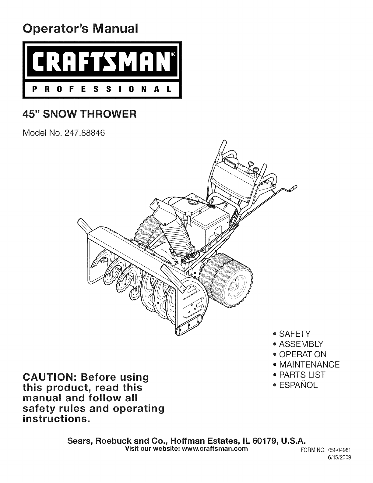
45" SNOW THROWER
Model No. 247.88846
CAUTION: Before using
this product, read this
manual and follow all
safety rules and operating
instructions.
Sears, Roebuck and Co., Hoffman Estates, IL 60179, U.S.A.
Visit our website: www.craftsman.com FORMNO.769-04981
, SAFETY
, ASSEMBLY
, OPERATION
, MAINTENANCE
, PARTS LIST
o ESPArqOL
6/15/2009
Page 2
WarrantyStatement..................................Page2
SafeOperation Practices .......................... Pages 3-6
Safety Labels ............................................ Page 7
Assembly .................................................. Pages 8-12
Operation .................................................. Pages 13-16
Service and Maintenance ......................... Pages 17-24
Off-Season Storage .................................. Page 25
Troubleshooting ........................................ Page 26
Parts List ................................................... Page 28-40
Repair Protection Agreement ................... Page 45
Espa_ol ..................................................... Page 46
Service Numbers ...................................... Back Cover
CRAFTSMAN PROFESSIONALFULL WARRANTY
Whenoperatedand maintainedaccordingtoallsuppliedinstructions,ifthis CraftsmanProfessionalsnowthrowerfailsduetoa defectinmaterial
orworkmanshipwithintwoyearsfromthedateofpurchase,call1-800-4-MY-HOME(1-800-469-4663)toarrangeforfreein-homerepair(or
replacementifrepairprovesimpossible).
Thiswarrantyappliesforonlyone yearfromthedateof purchaseifthis productiseverusedforcommercialor rentalpurposes.
ThiswarrantycoversONLYdefectsinmaterialandworkmanship.SearswillNOTpayfor:
• Expendableitemsthatbecomewornduringnormaluse,includingbutnotlimitedtoaugerbladesorpaddles,driftcutters,skidshoes,
shaveplate,shearpins,sparkplug,air cleaner,belts,andoilfilter.
• Standardmaintenanceservicing,oilchanges,ortune-ups.
• Tirereplacementorrepaircausedbypuncturesfromoutsideobjects,suchasnails,thorns,stumps,orglass.
• Tireor wheelreplacementor repairresultingfromnormalwear,accident,orimproperoperationormaintenance.
• Repairsnecessarybecauseof operatorabuse,includingbutnotlimitedtodamagecausedbyover-speedingtheengine,or from
impactingobjectsthatbendtheframe,augershaft,etc.
• Repairsnecessarybecauseof operatornegligence,includingbutnotlimitedto,electricalandmechanical
damagecausedbyimproperstorage,failureto usethepropergradeandamountofengineoil, or failureto maintaintheequipment
accordingtothe instructionscontainedintheoperator'smanual.
• Engine(fuelsystem)cleaningorrepairscausedbyfuel determinedto becontaminatedoroxidized(stale).In
general,fuelshouldbeusedwithin30 daysof itspurchasedate.
• Normaldeteriorationandwearoftheexteriorfinishes,orproductlabelreplacement.
Thiswarrantyappliesonlywhilethisproductiswithinthe UnitedStates.
Thiswarrantygivesyouspecificlegalrights,andyou mayalsohaveotherrightswhichvaryfromstatetostate.
Sears, Roebuckand Co., Hoffman Estates,IL 60179
EngineOilCapacity: 37ounces
FuelCapacity: Approx.5 Quarts
SparkPlug: TorchF6RTC(951-10292)
SparkPlugGap: .020"to.030"
©SearsBrands,LLC
Serial Number .................................................................
Dateof Purchase.............................................................
Recordthemodelnumber,serialnumber
anddateof purchaseabove
2
Page 3
Thissymbolpointsout importantsafetyinstructionswhich,if not
followed,couldendangerthepersonalsafetyand/orpropertyof
yourselfandothers. Readandfollowallinstructionsin thismanual
beforeattemptingtooperatethismachine.Failuretocomplywith
theseinstructionsmayresultin personalinjury.Whenyou seethis
symbol,HEEDITSWARNING!
Thismachinewasbuiltto beoperatedaccordingtothesafeopera-
tionpracticesinthis manual.As withanytypeof powerequipment,
carelessnessorerroron the partofthe operatorcanresultin serious
injury.Thismachineiscapableofamputatingfingers,hands,toes
andfeetandthrowingdebris.Failuretoobservethefollowingsafety
instructionscouldresultin seriousinjuryordeath.
CALIFORNIA PROPOSITION 65
EngineExhaust,someof itsconstituents,andcertainvehicle
componentscontainoremitchemicalsknowntoStateof California
tocausecancerandbirthdefectsorotherreproductiveharm,
TRAiNiNG
• Read,understand,andfollowall instructionsonthe machineand
in themanual(s)beforeattemptingtoassembleandoperate.
Failuretodo socan resultinseriousinjurytotheoperatorand/
orbystanders.Keepthismanualin a safeplaceforfutureand
regularreferenceandfororderingreplacementparts.Forques-
tionscall,1-800-4MY-HOME.
• Befamiliarwithall controlsandtheir properoperation.Knowhow
tostopthe machineanddisengagethemquickly.
Neverallowchildrenunder14yearsofageto operatethis
machine.Children14andovershouldreadandunderstandthe
instructionsandsafeoperationpracticesin thismanualandon
themachineandbe trainedandsupervisedbyanadult.
Neverallowadultsto operatethismachinewithoutproper
instruction.
• Thrownobjectscancauseseriouspersonalinjury.Planyour
snow-throwingpatterntoavoiddischargeof materialtoward
roads,bystandersandthe like.
Keepbystanders,petsandchildrenat least75feetfromthe
machinewhileitisinoperation.Stopmachineifanyoneenters
thearea.
Exercisecautiontoavoidslippingor falling,especiallywhen
operatinginreverse.
Your Responsibility--Restrict the useofthis powermachineto
personswhoread,understandandfollowthewarningsandinstruc-
tionsin thismanualandonthemachine,
SAVE THESE INSTRUCTIONS!
PREPARATION
Thoroughlyinspecttheareawheretheequipmentisto beused.
Removeall doormats,newspapers,sleds,boards,wiresandother
foreignobjects,whichcouldbe trippedoverorthrownbytheauger/
impeller.
Alwayswearsafetyglassesoreyeshieldsduringoperationand
whileperformingan adjustmentor repairto protectyoureyes.
Thrownobjectswhichricochetcancauseseriousinjurytothe
eyes.
Donot operatewithoutwearingadequatewinteroutergarments.
Donot wearjewelry,longscarvesorotherlooseclothing,which
couldbecomeentangledinmovingparts.Wearfootwearwhich
willimprovefootingonslipperysurfaces.
Usea groundedthree-wireextensioncordand receptacleforall
machineswithelectricstartengines.
Disengageallcontrolleversbeforestartingtheengine.
Adjustcollectorhousingheightto cleargravelorcrushedrock
surfaces.
Neverattempttomakeanyadjustmentswhileengineis running,
exceptwherespecificallyrecommendedintheoperator'smanual.
Letengineandmachineadjustto outdoortemperaturebefore
startingtoclearsnow.
3
Page 4
SafeHandling of Gasoline
Toavoidpersonalinjuryor propertydamageuseextremecarein
handlinggasoline.Gasolineisextremelyflammableandthevaporsare
explosive.Seriouspersonalinjurycanoccurwhengasolineisspilled
onyourselforyourclotheswhichcan ignite.Washyourskinand
changeclothesimmediately.
• Useonlyanapprovedgasolinecontainer.
• Extinguishall cigarettes,cigars,pipesandothersources
ofignition.
• Neverfuelmachineindoors.
• Neverremovegascapor addfuelwhiletheengineishot
or running.
• Allowengineto coolat leasttwominutesbeforerefueling.
• Neveroverfill fueltank.Filltanktono morethan1/2inch
belowbottomoffiller neckto providespaceforfuel
expansion.
• Replacegasolinecapandtightensecurely.
• Ifgasolineis spilled,wipeit offtheengineandequipment.
Movemachinetoanotherarea.Wait5 minutesbefore
startingtheengine.
• Neverstorethemachineorfuel containerinsidewhere
thereis anopenflame,sparkorpilotlight(e.g.furnace,
waterheater,spaceheater,clothesdryeretc.).
• Allowmachinetocoolat least5 minutesbeforestoring.
• Neverfillcontainersinsidea vehicleorona truckor trailer
bedwitha plasticliner.Alwaysplacecontainersonthe
groundawayfromyourvehiclebeforefilling.
• If possible,removegas-poweredequipmentfromthetruck
ortrailerand refuelitontheground.Ifthisis not possible,
thenrefuelsuchequipmentona trailerwithaportable
container,ratherthanfromagasolinedispensernozzle.
• Keepthenozzleincontactwiththe rimofthefueltankor
containeropeningatalltimesuntilfuelingiscomplete.Do
notuse a nozzlelock-opendevice.
OPERATION
• Do notputhandsorfeetnear rotatingparts,in the auger/impeller
housingorchuteassembly.Contactwiththerotatingpartscan
amputatehandsandfeet.
• Theauger/impellercontrolleverisa safetydevice.Neverbypass
itsoperation.Doingsomakesthe machineunsafeandmaycause
personalinjury.
• Thecontrolleversmustoperateeasilyin bothdirectionsand
automaticallyreturntothedisengagedpositionwhenreleased.
• Neveroperatewitha missingor damagedchuteassembly.Keep
all safetydevicesinplaceandworking.
• Neverrunanengineindoorsor ina poorlyventilatedarea.Engine
exhaustcontainscarbonmonoxide,anodorlessanddeadlygas.
• Do notoperatemachinewhileundertheinfluenceofalcoholor
drugs.
• Mufflerandenginebecomehotandcan causea burn.Donot
touch.Keepchildrenaway.
• Exerciseextremecautionwhenoperatingonorcrossinggravel
surfaces.Stayalertforhiddenhazardsortraffic.
• Exercisecautionwhenchangingdirectionandwhileoperatingon
slopes.
• Planyoursnow-throwingpatternto avoiddischargetowards
windows,walls,carsetc. Thus,avoidingpossibleproperty
damageorpersonalinjurycausedby a ricochet.
• Neverdirectdischargeatchildren,bystandersand petsor allow
anyoneinfrontof themachine.
• Donot overloadmachinecapacityby attemptingtoclearsnowat
toofastof arate.
• Neveroperatethismachinewithoutgoodvisibilityorlight.Always
be sureofyourfootingandkeepafirmholdon the handles.Walk,
neverrun.
• Disengagepowertotheauger/impellerwhentransportingor not
in use.
• Neveroperatemachineathightransportspeedsonslippery
surfaces.Lookdownand behindand usecarewhenbackingup.
• Ifthemachineshouldstartto vibrateabnormally,stopthe engine,
disconnectthe sparkplugwire andgrounditagainsttheengine.
Inspectthoroughlyfor damage.Repairanydamagebefore
startingandoperating.
• Disengageallcontrolleversandstopenginebeforeyouleave
theoperatingposition(behindthehandles).Waituntiltheauger/
impellercomestoa completestopbeforeuncloggingthechute
assembly,makinganyadjustments,orinspections.
• Neverputyourhandinthedischargeorcollectoropenings.Do
notunclogchuteassemblywhileengineis running.Shutoff
engineand remainbehindhandlesuntilallmovingpartshave
stoppedbeforeunclogging.
• Useonlyattachmentsandaccessoriesapprovedbythemanufac-
turer(e.g.wheelweights,tirechains,cabsetc.).
• Whenstartingengine,pullcordslowlyuntilresistanceisfelt,then
pull rapidly.Rapidretractionofstartercord(kickback)willpull
handandarmtowardenginefasterthanyoucanlet go.Broken
bones,fractures,bruisesorsprainscouldresult.
• Ifsituationsoccurwhichare notcoveredinthismanual,usecare
andgoodjudgment.ContactCustomerSupportforassistance
andthenameofyour nearestservicingdealer.
CLEARING A CLOGGED DISCHARGE CHUTE
Handcontactwiththe rotatingimpellerinsidethedischargechute
is themostcommoncauseofinjuryassociatedwithsnowthrowers.
Neveruseyourhandtocleanoutthedischargechute.
Toclear thechute:
1. SHUTTHEENGINEOFF!
2. Wait 10secondstobe suretheimpellerbladeshavestopped
rotating.
3. Alwaysusea clean-outtool,not yourhands.
4
Page 5
MAINTENANCE & STORAGE
• Nevertamperwithsafetydevices.Checktheirproperoperation
regularly.Refertothe maintenanceandadjustmentsectionsof
thismanual.
• Beforecleaning,repairing,or inspectingmachinedisengageall
controlleversandstoptheengine.Waituntilthe auger/impeller
cometoa completestop.Disconnectthe sparkplugwireand
groundagainsttheengineto preventunintendedstarting.
Checkboltsand screwsfor propertightnessatfrequentintervals
tokeepthemachineinsafeworkingcondition.Also,visually
inspectmachineforanydamage.
Donotchangetheenginegovernorsettingor over-speedthe
engine.Thegovernorcontrolsthe maximumsafeoperatingspeed
ofthe engine.
Snowthrowershaveplatesandskidshoesaresubjecttowear
anddamage.Foryoursafetyprotection,frequentlycheckall
componentsandreplacewithoriginalequipmentmanufacturer's
(OEM)partsonly."Useofpartswhichdo not meettheoriginal
equipmentspecificationsmayleadto improperperformanceand
compromisesafety!"
Checkcontrolleversperiodicallytoverifytheyengageanddisen-
gageproperlyandadjust,ifnecessary.Refertothe adjustment
sectioninthisoperator'smanualforinstructions.
Maintainor replacesafetyandinstructionlabels,as necessary.
• Observeproperdisposallawsand regulationsforgas,oil,etc. to
protecttheenvironment.
Priorto storing,runmachinea few minutestoclearsnowfrom
machineand preventfreezeupofauger/impeller.
Neverstorethemachineorfuel containerinsidewherethereisan
openflame,sparkorpilot lightsuchasa waterheater,furnace,
clothesdryeretc.
Alwaysrefertothe operator'smanualforproperinstructionson
off-seasonstorage.
Checkfuelline,tank, cap,andfittingsfrequentlyfor cracksor
leaks.Replaceif necessary.
Donotcrankenginewithsparkplugremoved.
Accordingtothe ConsumerProductsSafetyCommission(CPSC)
andtheU.S.EnvironmentalProtectionAgency(EPA),thisproduct
hasan AverageUsefulLifeof seven(7)years,or60 hoursof
operation.At the endoftheAverageUsefulLifehavethemachine
inspectedannuallybyan authorizedservicedealertoensurethat
allmechanicalandsafetysystemsareworkingproperlyand not
wornexcessively.Failuretodo socanresultinaccidents,injuries
ordeath.
DO NOT MODIFY ENGINE
Toavoidseriousinjuryor death,donotmodifyengineinany way.
Tamperingwiththegovernorsettingcanleadtoa runawayengineand
causeitto operateat unsafespeeds.Nevertamperwithfactorysetting
ofenginegovernor.
NOTICE REGARDING EMiSSiONS
EngineswhicharecertifiedtocomplywithCaliforniaandfederal
EPAemissionregulationsforSORE(SmallOff RoadEquipment)are
certifiedto operateonregularunleadedgasoline,and mayinclude
thefollowingemissioncontrolsystems:EngineModification(EM),
OxidizingCatalyst(OC),SecondaryAirInjection(SAI)and ThreeWay
Catalyst(TWO)if soequipped.
SPARK ARRESTOR
Thismachineisequippedwithaninternalcombustionengineand
shouldnotbe usedonornearanyunimprovedforest-covered,
brush-coveredorgrass-coveredlandunlesstheengine'sexhaust
systemisequippedwitha sparkarrestermeetingapplicablelocalor
statelaws(if any)
Ifa sparkattesterisused,itshouldbemaintainedineffectiveworking
orderbytheoperator.Inthe StateofCaliforniatheaboveis required
bylaw (Section4442oftheCaliforniaPublicResourcesCode).Other
statesmayhavesimilarlaws. Federallawsapplyonfederallands.
A sparkarresterforthemufflerisavailablethroughyournearestSears
PartsandRepairServiceCenter.
Page 6
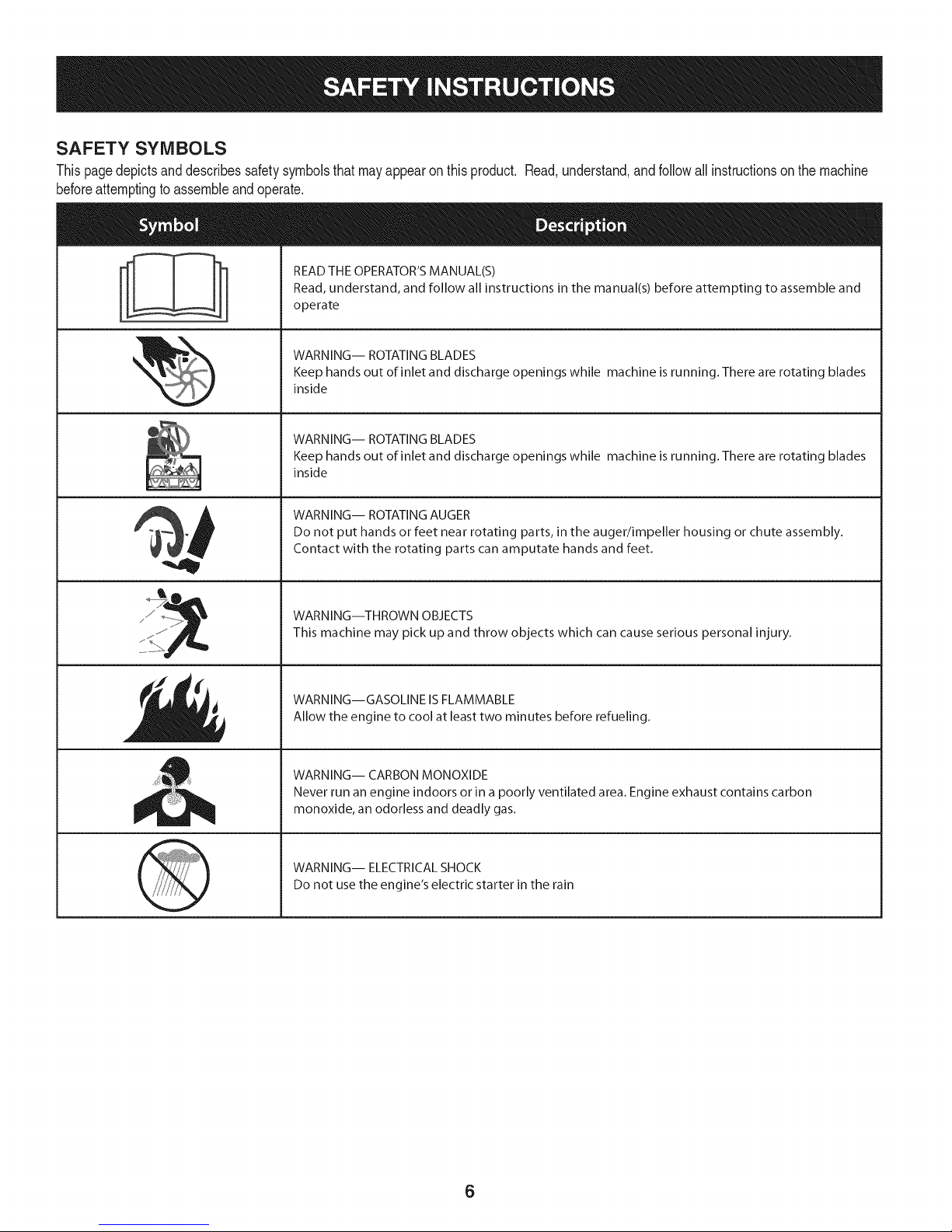
SAFETY SYMBOLS
Thispagedepictsanddescribessafetysymbolsthatmayappearonthisproduct. Read,understand,andfollowall instructionson themachine
beforeattemptingtoassembleandoperate.
READ THE OPERATOR'S MANUAL(S)
i
i
Read, understand, and follow all instructions in the manual(s) before attempting to assemble and
operate
WARNING-- ROTATING BLADES
Keep hands out of inlet and discharge openings while machine is running. There are rotating blades
inside
WARNING-- ROTATING BLADES
Keep hands out of inlet and discharge openings while machine is running. There are rotating blades
inside
WARNING-- ROTATING AUGER
Do not put hands or feet near rotating parts, in the auger/impeller housing or chute assembly.
Contact with the rotating parts can amputate hands and feet.
WARNING--THROWN OBJECTS
This machine may pick up and throw objects which can cause serious personal injury.
WARNING--GASOLINE IS FLAMMABLE
Allow the engine to cool at least two minutes before refueling.
WARNING-- CARBON MONOXIDE
Never run an engine indoors or in a poorly ventilated area. Engine exhaust contains carbon
monoxide, an odorless and deadly gas.
WARNING-- ELECTRICAL SHOCK
Do not use the engine's electric starter in the rain
6
Page 7
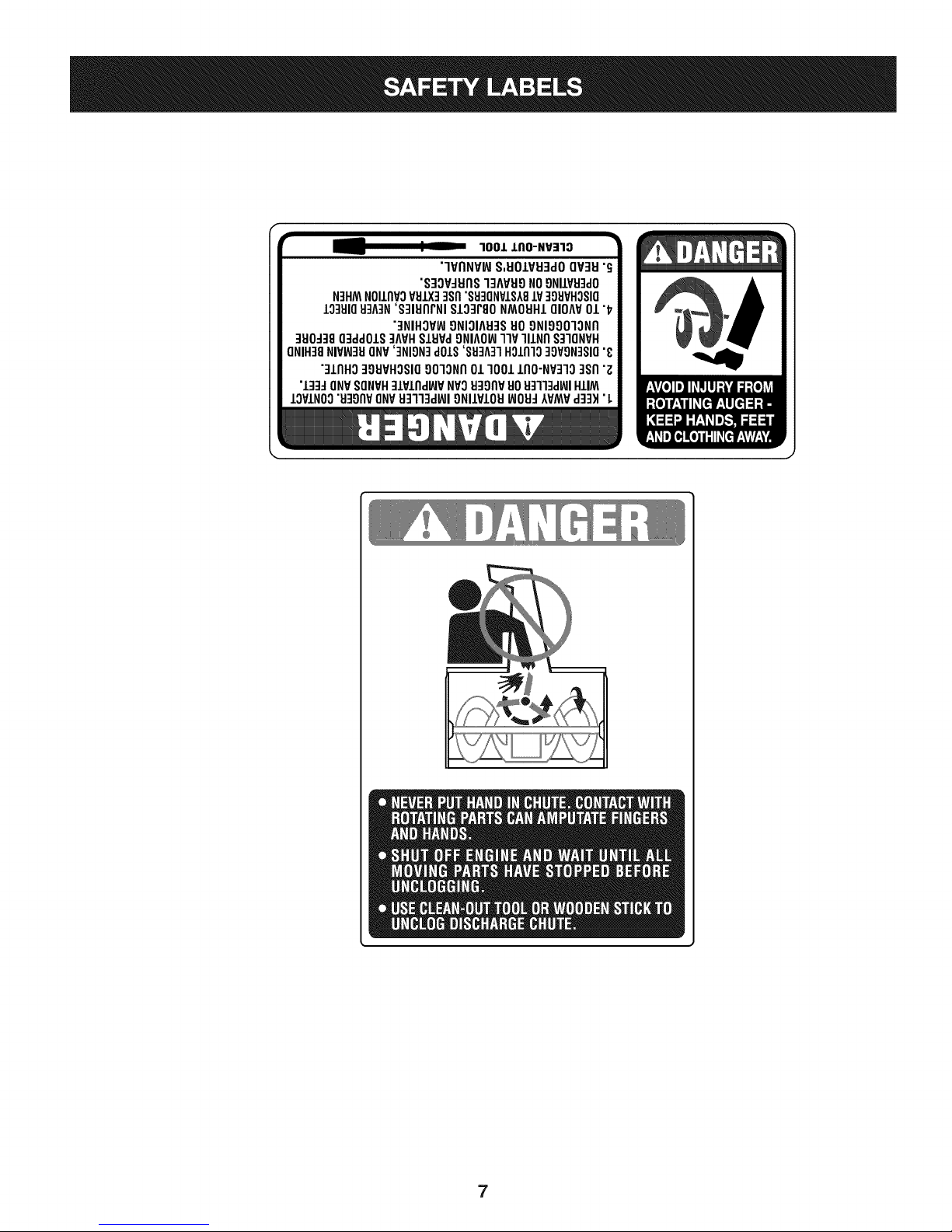
100JL J,IIO-NV=IlO
"'IVI1NVIAIS,EIOIVEI:IdOQV3EI"_
"S:IOV:IEI(1S"IqAVEI9NO9NIlVEIqdO
N]HMNOIII1VOVBIX]]SI1"SEI3ONVISA8IV]gEIVHOSIO
10qBI0BLAIN'S:IIEIIlrNI$103r80 NMOEIHLQIOAV01 "17
"3NIHOVW9NIOIAB:ISBO9NIOOOlON[I
qElO-1:18O]ddOlS:IAVHSIEIVa£)NIAO_llP lllNI1 S:IIONVH
ONIH]8NIVW]BONV']NION]d01S'SB]A31H011110qOVgN]SIO"_
":llrlHO39EIVHOSIO9010NI101 10011[10-NV31038rl"z
•133JQNV8QNVH]lPllldBJP NVOEI3_)I1VBOB:lll:kl_l HIlM
IOVINO0"EI:IO[1VONVB::lll:ld_JIONIIVIOB_OB:IAVMVdq:lH•L
7
Page 8
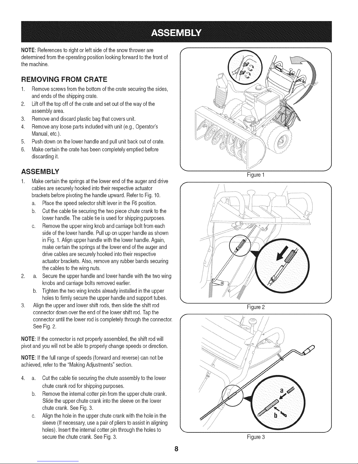
NOTE:Referencesto rightorleft sideofthesnowthrowerare
determinedfromthe operatingpositionlookingforwardtothefrontof
themachine.
REMOVING FROM CRATE
1. Removescrewsfromthebottomof thecratesecuringthesides,
andendsof theshippingcrate.
2. Liftoff the topoffofthecrateandsetoutof thewayof the
assemblyarea.
3. Removeanddiscardplasticbagthatcoversunit.
4. Removeanyloosepartsincludedwithunit(e.g.,Operator's
Manual,etc.).
5. Pushdownonthelowerhandleandpullunit backoutofcrate.
6. Makecertainthecratehasbeencompletelyemptiedbefore
discardingit.
ASSEMBLY
1. Makecertainthe springsatthe lowerendoftheaugeranddrive
cablesaresecurelyhookedintotheir respectiveactuator
bracketsbeforepivotingthehandleupward.Referto Fig. 10.
a. Placethe speedselectorshiftleverin theF6position.
b. Cutthecabletie securingthetwopiecechutecranktothe
lowerhandle.Thecable tieisusedfor shippingpurposes.
c. Removethe upperwingknobandcarriageboltfromeach
sideof thelowerhandle.Pulluponupperhandleasshown
in Fig.1.Alignupperhandlewiththe lowerhandle.Again,
makecertainthespringsat thelowerendoftheaugerand
drivecablesaresecurelyhookedintotheirrespective
actuatorbrackets.Also,removeanyrubberbandssecuring
thecablesto thewingnuts.
2. a. Securetheupperhandleandlowerhandlewiththetwo wing
knobsandcarriageboltsremovedearlier.
b. Tightenthetwo wingknobsalreadyinstalledin theupper
holesto firmlysecuretheupperhandleand supporttubes.
3. Alignthe upperand lowershiftrods,thenslidetheshift rod
connectordownoverthe endofthelowershift rod.Tapthe
connectoruntilthelower rodiscompletelythroughtheconnector.
See Fig.2.
Y
Figure 1
/
J
NOTE:If theconnectoris notproperlyassembled,theshiftrodwill
pivotand youwillnotbeabletoproperlychangespeedsordirection.
NOTE:If thefullrangeof speeds(forwardandreverse)cannot be
achieved,referto the "MakingAdjustments"section.
.
a. Cutthecabletie securingthechuteassemblyto thelower
chutecrankrodforshippingpurposes.
b. Removethe internalcotterpinfromtheupperchutecrank.
Slidetheupperchutecrankinto thesleeveon the lower
chutecrank.See Fig.3.
c. Alignthe holein theupperchutecrankwiththe holeinthe
sleeve(Ifnecessary,useapairof plierstoassistinaligning
holes).Inserttheinternalcotterpinthroughtheholesto
securethechutecrank.SeeFig.3.
Figure3
8
Page 9
5. Removelocknutsandscrewssecuringoneofthe flangekeepers
tothe chuteassembly.
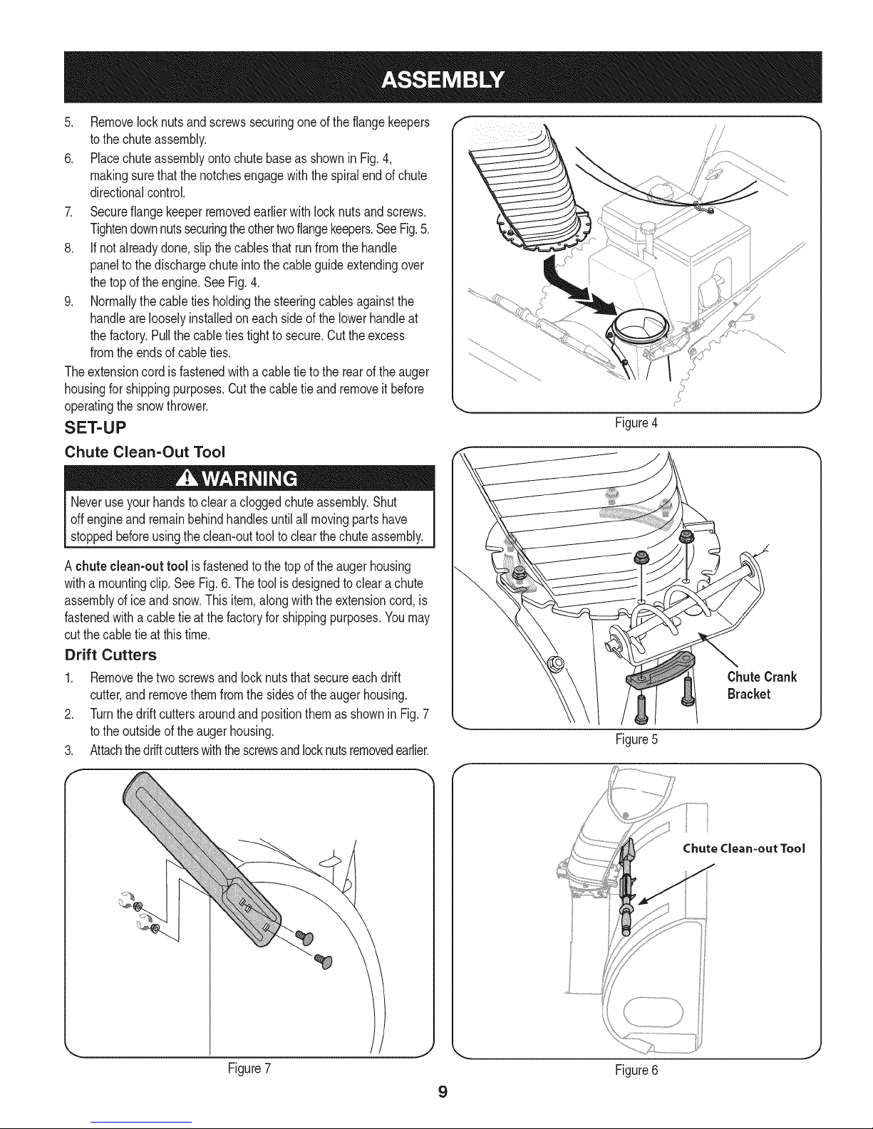
6. Placechuteassemblyontochutebaseas showninFig.4,
makingsurethatthe notchesengagewiththespiralendofchute
directionalcontrol.
7. Secureflangekeeperremovedearlierwithlocknutsandscrews.
Tightendownnutssecuringtheothertwoflangekeepers.SeeFig.5.
8. If notalreadydone,slipthe cablesthat runfromthehandle
paneltothe dischargechuteintothecableguideextendingover
thetopofthe engine.SeeFig.4.
9. Normallythecabletiesholdingthesteeringcablesagainstthe
handlearelooselyinstalledoneachsideofthe lowerhandleat
thefactory.Pullthecableties tighttosecure.Cuttheexcess
fromtheendsof cableties.
Theextensioncordis fastenedwithacabletie to therearoftheauger
housingforshippingpurposes.Cutthecabletie andremoveit before
operatingthesnowthrower.
SET-UP
Chute Clean=Out Tool
Neveruseyourhandsto clearacloggedchuteassembly.Shut
off engineandremainbehindhandlesuntilallmovingpartshave
stoppedbeforeusingtheclean-outtoolto clearthechuteassembly.
J
Figure4
A chuteclean-outtool isfastenedtothetop oftheaugerhousing
witha mountingclip.SeeFig.6.Thetoolisdesignedtoclearachute
assemblyofice andsnow.Thisitem,alongwiththeextensioncord,is
fastenedwithacable tieatthefactoryfor shippingpurposes.Youmay
cutthecabletieat thistime.
Drift Cutters
1. Removethetwo screwsand locknutsthat secureeach drift
cutter,andremovethemfromthesidesof theaugerhousing.
2. Turnthedriftcuttersaroundandpositionthemas shownin Fig.7
tothe outsideoftheaugerhousing.
3. Attachthedriftcutterswiththescrewsandlocknutsremovedearlier.
F-
ChuteCrank
Bracket
J
Figure5
f
Chute Clean=out Tool
Figure7
J
Figure6
9
Page 10
Tire Pressure (Pneumatic Tires)
Underanycircumstancedonotexceedmanufacturer'srecom-
mendedpsi.Equaltire pressureshouldbemaintainedat alltimes.
Excessivepressurewhenseatingbeadsmaycausetire/rim
assemblytoburstwithforcesufficienttocauseseriousinjury.Refer
to sidewallof tireforrecommendedpressure.
Thetirescan beover-inflatedforshippingpurposes.Checkthetire
pressurebeforeoperatingthe snowthrower. Refertothetire sidewall
for rnanufactures'srecommendedpsianddeflate(or inflate)thetires
as necessary.
NOTE:Equaltirepressureisto bemaintainedatalltimesforperfor-
mancepurposes.
Fuel Recommendations
Useautomotivegasoline(unleadedor low leadedto minimizecombus-
tionchamberdeposits)witha minimumof 87 octane.Gasolinewith
upto 10%ethanolor15%MTBE(MethylTertiaryButylEther)canbe
used.Neverusean oil/gasolinemixtureordirty gasoline.Avoidgetting
dirt, dust,orwaterinthefueltank.DONOTuse E85gasoline.
• Refuelina well-ventilatedareawiththeenginestopped.Donot
smokeorallowflamesor sparksintheareawheretheengineis
refueledor wheregasolineisstored.
• Donot overfillthefueltank. Afterrefueling,makesurethetank
capis closedproperlyandsecurely.
• Becarefulnotto spillfuelwhenrefueling.Spilledfuel orfuel vapor
mayignite.Ifany fuelis spilled,makesuretheareaisdry before
startingtheengine.
• Avoidrepeatedor prolongedcontactwithskinor breathingofvapor.
Adding Fuel
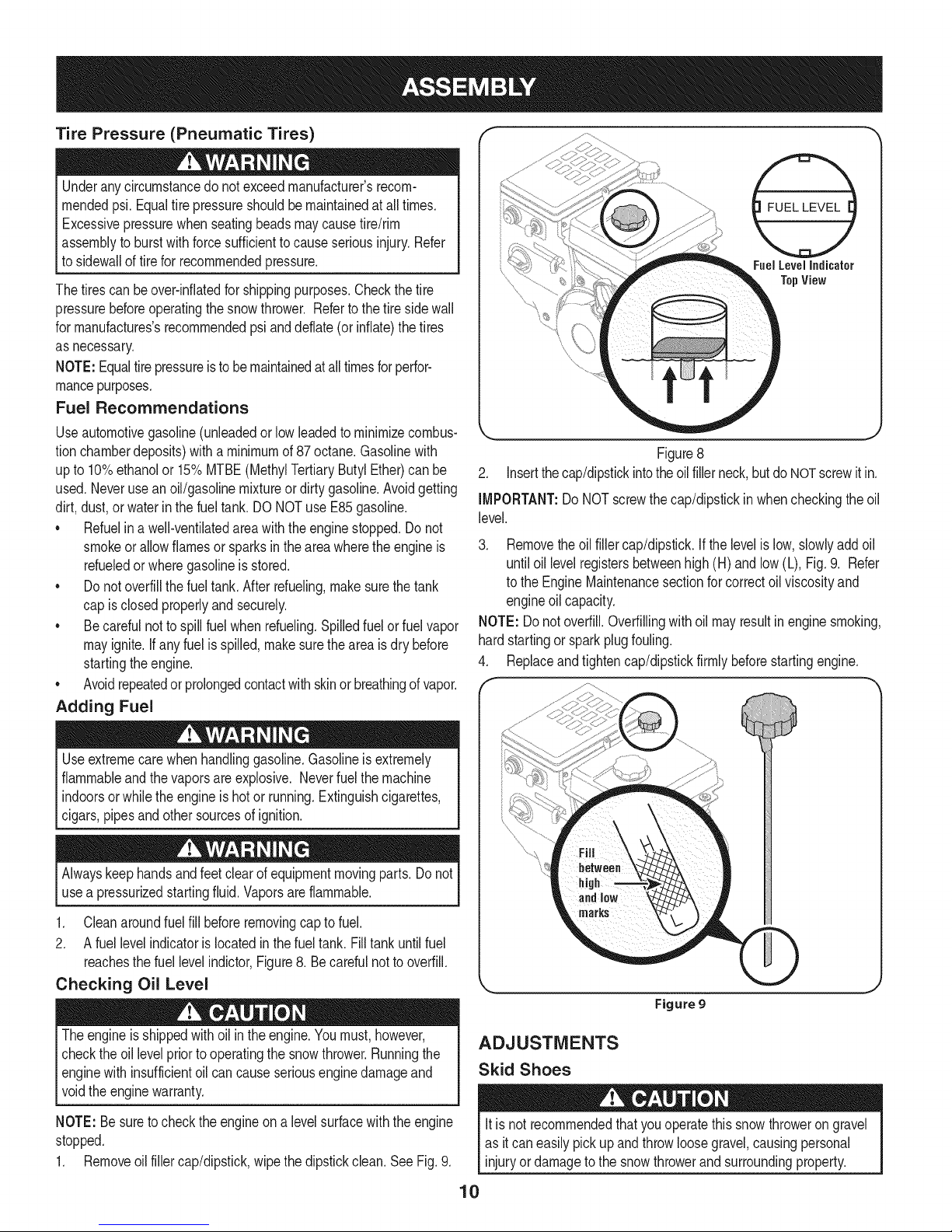
Fuel Level Indicator
TopView
Figure8
2. Insertthecap/dipstickintotheoilfillerneck,butdoNOTscrewit in.
IMPORTANT:DoNOTscrewthecap/dipstickinwhencheckingtheoil
level.
3. Removethe oilfillercap/dipstick.Ifthelevelis low,slowlyaddoil
untiloil levelregistersbetweenhigh(H) andlow (L),Fig.9. Refer
tothe EngineMaintenancesectionforcorrectoilviscosityand
engineoil capacity.
NOTE:Do notoverfill.Overfillingwithoilmayresultinenginesmoking,
hardstartingor sparkplugfouling.
4. Replaceandtightencap/dipstickfirmlybeforestartingengine.
Useextremecarewhenhandlinggasoline.Gasolineisextremely
flammableandthe vaporsareexplosive.Neverfuelthemachine
indoorsorwhile theengineishotor running.Extinguishcigarettes,
cigars,pipesandothersourcesofignition.
usea pressurizedstartingfluid.Vaporsareflammable.
1. Cleanaroundfuelfillbeforeremovingcaptofuel.
2. A fuel levelindicatorislocatedinthefueltank.Filltankuntilfuel
reachesthefuel levelindictor,Figure8. Becarefulnottooverfill.
Checking Oil Level
Theengineis shippedwithoilintheengine.Youmust,however,
checkthe oil levelpriortooperatingthe snowthrower.Runningthe
enginewith insufficientoil cancauseseriousenginedamageand
[vo d theengne warranty.
NOTE:Be suretochecktheengineon a levelsurfacewiththeengine
stopped.
1. Removeoil fillercap/dipstick,wipethedipstickclean.SeeFig.9.
Figure g
ADJUSTMENTS
Skid Shoes
itis notrecommendedthatyouoperatethissnowthrowerongravel
asit caneasilypickupand throwloosegravel,causingpersonal
injuryordamagetothe snowthrowerandsurroundingproperty.
10
Page 11
Thesnowthrowerskidshoesareadjustedupwardatthefactoryforship-
pingpurposes.Adjustthemdownwardpriortooperatingthe machine.
• Forclosesnowremovalona smoothsurface,raiseskidshoes
higherontheaugerhousing.
• Useamiddleorlowerpositionwhentheareatobeclearedisuneven.
NOTE:Ifyou choosetooperatethesnowthroweron agravelsurface,
keepthe skidshoesin positionformaximumclearancebetweenthe
groundandtheshaveplate.
Toadjusttheskidshoes:
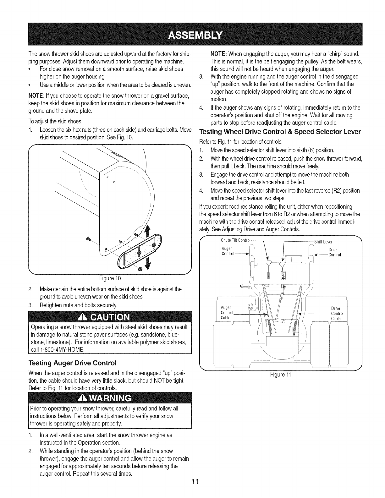
1. Loosenthesixhexnuts(threeoneachside)andcarriagebolts.Move
skidshoestodesiredposition.SeeFig.10.
NOTE:Whenengagingtheauger,youmayheara "chirp"sound.
Thisisnormal,itisthe beltengagingthepulley.Asthebeltwears,
this soundwillnotbeheardwhenengagingtheauger.
3. Withtheenginerunningandtheaugercontrolin thedisengaged
"up"position,walktothe frontof themachine.Confirmthatthe
augerhascompletelystoppedrotatingandshowsno signsof
motion.
4. Iftheaugershowsany signsof rotating,immediatelyreturntothe
operator'spositionandshutoff theengine.Waitfor all moving
partsto stopbeforereadjustingtheaugercontrolcable.
Testing Wheel Drive Control & Speed Selector Lever
RefertoFig.11forlocationofcontrols.
1. Movethespeedselectorshiftleverintosixth(6)position.
2. Withthewheeldrivecontrolreleased,pushthesnowthrowerforward,
thenpullit back.Themachineshouldmovefreely.
3. Engagethedrivecontrolandattemptto movethemachineboth
forwardandback,resistanceshouldbefelt.
4. Movethespeedselectorshiftleverintothefastreverse(R2)position
andrepeattheprevioustwosteps.
Ifyouexperiencedresistancerollingtheunit,eitherwhenrepositioning
thespeedselectorshiftleverfrom6 to R2orwhenattemptingto movethe
machinewiththedrivecontrolreleased,adjustthedrivecontrolimmedi-
ately.SeeAdjustingDriveandAugerControls.
Figure10
2. Makecertaintheentirebottomsurfaceofskidshoeisagainstthe
groundtoavoidunevenwearontheskidshoes.
3. Retightennutsandboltssecurely.
Operatinga snowthrowerequippedwithsteelskidshoesmayresult
in damagetonaturalstonepaversurfaces(e.g.sandstone,blue-
stone,limestone).Forinformationon availablepolymerskidshoes,
call1-800-4MY-HOME.
Testing Auger Drive Control
Whentheaugercontrolis releasedandin thedisengaged"up"posi-
tion,thecableshouldhaveverylittleslack,butshouldNOTbetight.
Referto Fig.11forlocationofcontrols.
Priortooperatingyoursnowthrower,carefullyreadandfollowall
instructionsbelow.Performall adjustmentsto verifyyoursnow
throwerisoperatingsafelyandproperly.
.
Ina well-ventilatedarea,startthesnowthrowerengineas
instructedin theOperationsection.
2.
Whilestandinginthe operator'sposition(behindthe snow
thrower),engagetheaugercontrolandallowtheaugertoremain
engagedfor approximatelyten secondsbeforereleasingthe
augercontrol.Repeatthisseveraltimes.
11
Auger
Control
Cable
Shift Lever
Drive
_(--.---- Control
Drive
Control
Cable
Figure11
Page 12
Adjusting Wheel Drive & Auger Controls
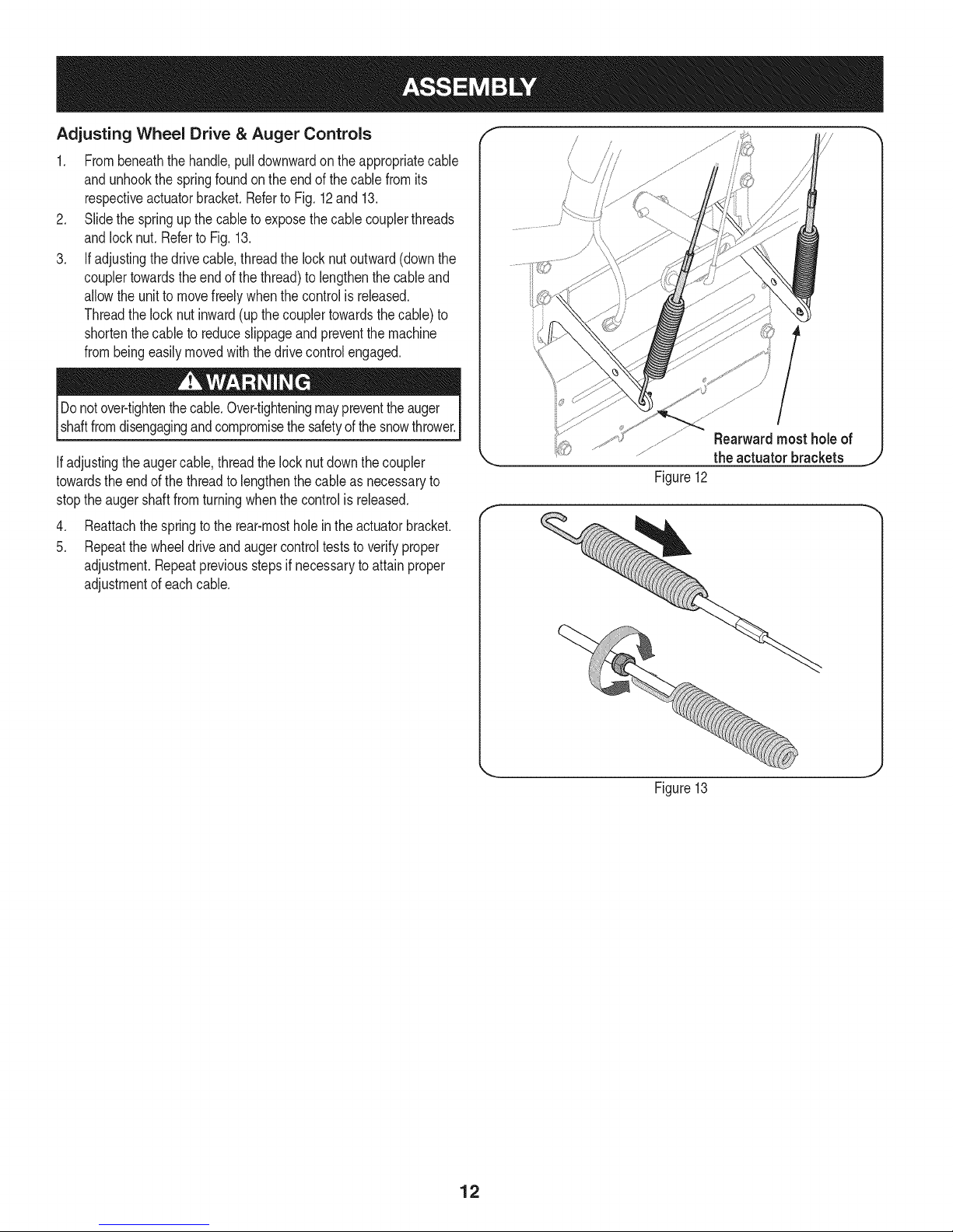
1. Frombeneaththehandle,pulldownwardonthe appropriatecable
andunhookthespringfoundontheendof thecablefromits
respectiveactuatorbracket.RefertoFig.12and13.
2. Slidethe springupthecableto exposethecablecouplerthreads
andlocknut.Referto Fig.13.
3. Ifadjustingthedrivecable,threadthelocknutoutward(downthe
couplertowardsthe endof thethread)tolengthenthecableand
allowthe unitto movefreelywhenthecontrolis released.
Threadthelocknutinward(up thecouplertowardsthecable)to
shortenthecable toreduceslippageandpreventthemachine
frombeingeasilymovedwiththedrivecontrolengaged.
Donotover-tightenthecable.Over-tighteningmaypreventtheauger
shaftfromdisengagingandcompromisethesafetyofthesnowthrower.
Ifadjustingtheaugercable,threadthelocknut downthecoupler
towardstheendof thethreadtolengthenthecableasnecessaryto
stoptheaugershaftfromturningwhenthecontrolis released.
4. Reattachthespringtotherear-mostholein theactuatorbracket.
5. Repeatthewheeldriveandaugercontrolteststoverifyproper
adjustment.Repeatpreviousstepsif necessarytoattainproper
adjustmentof eachcable.
Rearwardmost holeof
the actuator brackets
Figure12
J
Figure13
12
Page 13
f
DriftCutters
Drive Two-wayChuteControlTM
Headli<
ChuteAssembly
SpeedSelector
ShiftLever
_._-=-==AugerControl
Steering
Wheel Control
Clean-out Tool_
_!r'_Auger
Housing
SkidShoes
Figure
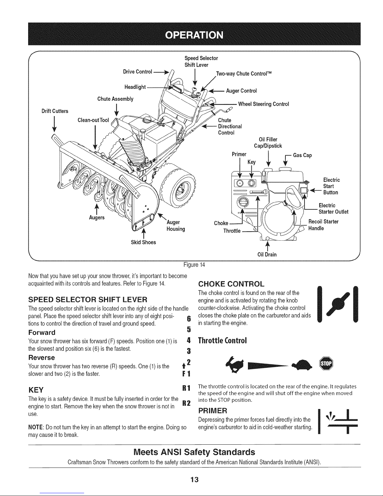
Nowthatyouhavesetupyoursnowthrower,it'simportanttobecome
acquaintedwithitscontrolsandfeatures.Referto Figure14.
SPEED SELECTOR SHIFT LEVER
Thespeedselectorshiftleveris locatedon therightsideofthehandle
panel.Placethespeedselectorshiftleverintoanyof eightposi- 6
tionstocontrolthedirectionoftravelandgroundspeed.
Forward 5
Yoursnowthrowerhassixforward(F) speeds.Positionone(1)is 4
theslowestandpositionsix(6) isthefastest. 3
Reverse
Yoursnowthrowerhastwo reverse(R) speeds.One(1)isthe t 2
slowerandtwo(2) isthefaster. F ]
Control
Oil Filler
Cap/Dipstick
Primer
Key
Throttle
_L=-GasCap
OilDrain
14
CHOKE CONTROL
Thechokecontrolis foundontherearof the
engineand isactivatedbyrotatingtheknob
counter-clockwise.Activatingthechokecontrol
closesthe chokeplateonthecarburetorandaids
instartingtheengine.
ThrottleControl
Electric
Start
Button
Electric
Outlet
RecoilStarter
Handle
KEY
Thekeyisa safetydevice.Itmustbefullyinsertedin orderforthe
enginetostart.Removethekeywhenthesnowthrowerisnotin
use.
NOTE:Do notturnthekeyin anattemptto starttheengine.Doingso
maycauseitto break.
CraftsmanSnowThrowersconformtothesafetystandardofthe AmericanNationalStandardsInstitute(ANSI).
R 1 The throttle control is located on the rear of the engine. It regulates
the speed of the engine and will shut off the engine when moved
into the STOP position.
R2
PRIMER
Depressingthe primerforcesfueldirectlyintothe
engine'scarburetorto aidin cold-weatherstarting.
Meets ANSI Safety Standards
13
Page 14
OIL FILL
Engineoillevelcan becheckedandoiladdedthroughtheoil fill.
RECOIL STARTER HANDLE
Thishandleisusedto manuallystarttheengine.
ELECTRIC STARTER BUTTON
Pressingtheelectricstarterbuttonengagestheengine'selectric
starterwhenpluggedintoa 120Vpowersource.
ELECTRIC STARTER OUTLET
Requirestheuseofa three-prongoutdoorextensioncord(included)
anda 120Vpowersource/walloutlet.
AUGERS
Whenengaged,the augersrotateanddrawsnowintotheauger
housing.
CHUTE ASSEMBLY
Snowdrawnintotheaugerhousingisdischargedoutthe chute
assembly.
GAS CAP
Unthreadthegascapto addgasolinetothefueltank.
f
DRIVE
CONTROL
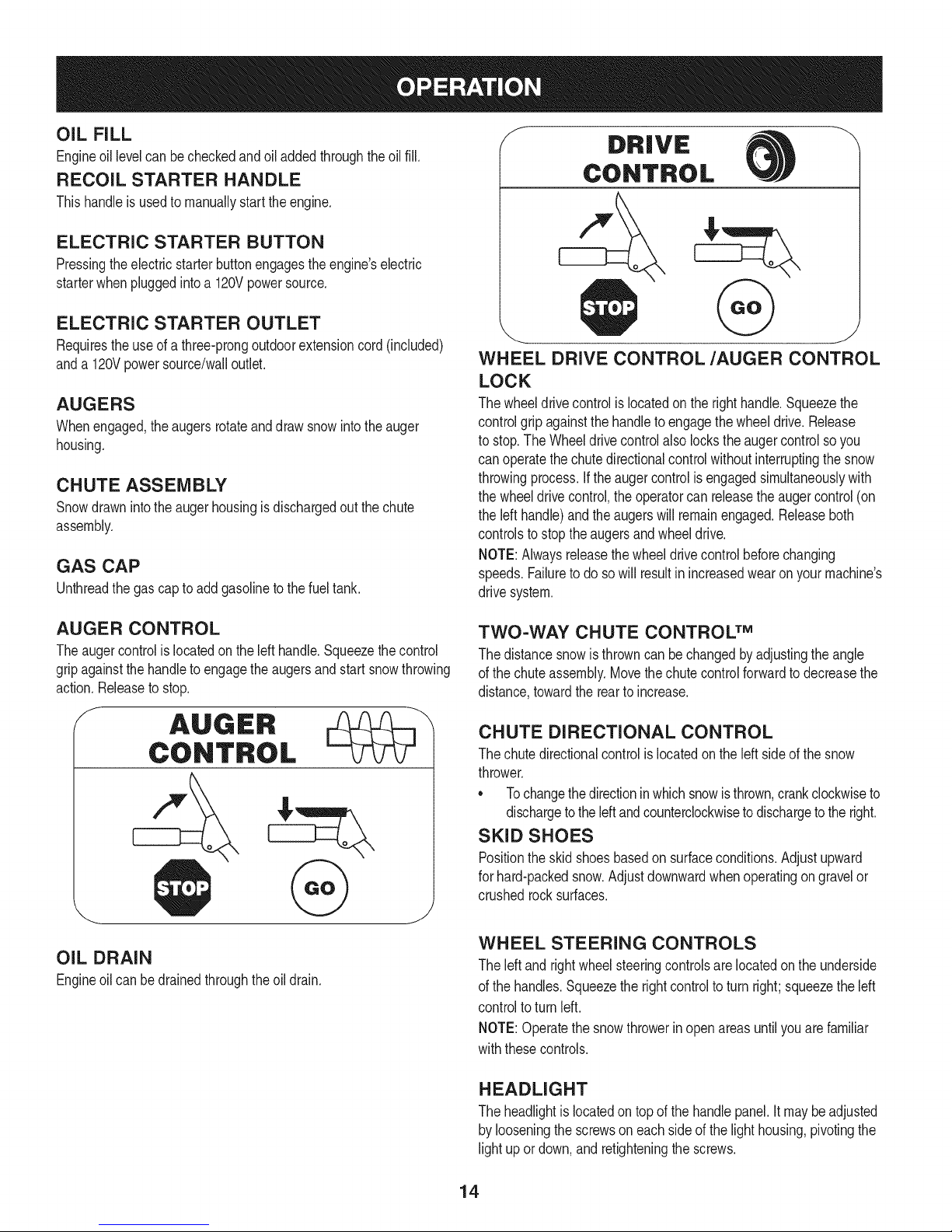
WHEEL DRIVE CONTROL/AUGER CONTROL
LOCK
Thewheeldrivecontrolis locatedon therighthandle.Squeezethe
controlgrip againstthehandletoengagethe wheeldrive.Release
to stop.TheWheeldrivecontrolalsolockstheaugercontrolsoyou
canoperatethechutedirectionalcontrolwithoutinterruptingthe snow
throwingprocess.Ifthe augercontrolisengagedsimultaneouslywith
thewheeldrivecontrol,theoperatorcanreleasetheaugercontrol(on
theleft handle)andtheaugerswillremainengaged.Releaseboth
controlsto stoptheaugersandwheeldrive.
NOTE:Alwaysreleasethewheeldrivecontrolbeforechanging
speeds.Failuretodo sowill resultinincreasedwearonyourmachine's
drivesystem.
AUGER CONTROL
Theaugercontrolis locatedontheleft handle.Squeezethecontrol
gripagainstthehandleto engagetheaugersandstartsnowthrowing
action.Releasetostop.
f
OIL DRAIN
Engineoilcanbedrainedthroughtheoil drain.
TWO-WAY CHUTE CONTROL TM
Thedistancesnowisthrowncan bechangedbyadjustingtheangle
ofthe chuteassembly.Movethe chutecontrolforwardtodecreasethe
distance,towardtherearto increase.
CHUTE DIRECTIONAL CONTROL
Thechutedirectionalcontrolis locatedontheleft sideofthe snow
thrower.
• Tochangethedirectioninwhichsnowisthrown,crankclockwiseto
dischargetothe leftandcounterclockwisetodischargetotheright.
SKID SHOES
Positiontheskidshoesbasedon surfaceconditions.Adjustupward
forhard-packedsnow.Adjustdownwardwhenoperatingongravelor
crushedrocksurfaces.
WHEEL STEERING CONTROLS
Theleftand rightwheelsteeringcontrolsare locatedontheunderside
ofthe handles.Squeezethe rightcontroltoturnright;squeezetheleft
controltoturn left.
NOTE:Operatethesnowthrowerin openareasuntilyouarefamiliar
withthesecontrols.
HEADLIGHT
Theheadlightislocatedontop ofthehandlepanel.It maybeadjusted
bylooseningthescrewsoneachsideof thelighthousing,pivotingthe
lightupor down,andretighteningthescrews.
14
Page 15
DRIFT CUTTERS
Thedrift cuttersaredesignedforuseindeepsnow.Theiruseis
optionalfornormalsnowconditions.Maneuverthesnowthrowerso
thatthecutterspenetrateahighstandingsnowdriftto assistsnow
fallingintotheaugersforthrowing.
CLEAN-OUT TOOL
Thechuteclean-outtoolisconvenientlyfastenedtotherearofthe
augerhousingwitha mountingclip. Shouldsnowandice become
lodgedin thechuteassemblyduringoperation,proceedasfollowsto
safelycleanthechuteassemblyandchuteopening:
Neveruseyour handstoclearacloggedchuteassembly.Shut
off engineand remainbehindhandlesuntilallmovingpartshave
stoppedbeforeunclogging.
1. ReleaseboththeAugerControland theWheeldrivecontrol.
2. Stopthe engineby removingthekey.
3. Removetheclean-outtoolfromthe clip whichsecuresittothe
rearoftheaugerhousing.
4. Usetheshovel-shapedendoftheclean-outtooltodislodgeand
scoopanysnowandice whichhasformedin andnearthechute
assembly.
5. Refastentheclean-outtooltothemountingclipontherearofthe
augerhousing,reinsertthekeyandstartthesnowthrower'sengine.
6. Whilestandingintheoperator'sposition(behindthe snow
thrower),engagetheaugercontrolforafewsecondsto clearany
remainingsnowandice fromthechuteassembly.
BEFORE STARTING ENGINE
Read,understand,andfollowall instructionsandwarningson the
machineandin thismanualbeforeoperating.
Oil
Theunit wasshippedwithoilintheengine.Checkoil levelbeforeeach
operationtoensureadequateoilin theengine.Forfurtherinstructions,
referto theService& Maintenancesectionofthismanual.
1. Removethedipstickfromtheoilfill.
2. Checkandmakesurethatthe levelofoil isuptothe FULLmark
onthedipstick.
NOTE:Do NOTscrewthe screwtheoilcapintochecktheoillevel.
3. If theoil levelisnot upto FULL,pourfreshmotoroil (5W-30,with
a minimumclassificationofSF/SG/SH/SJ)slowlythroughthe
opening.Replaceoil fill dipstickandcheckoillevelagain.
Gasoline
• Makesurethatthe containerfromwhichyoupourthegasolineis
cleanandfree fromrustorotherforeignparticles.
• Alwaysfillthe fuel tankoutdoorsandusea funnelor spoutto
preventspilling.
• Fillfuel tankwithclean,fresh,unleadedgasolinewitha minimum
of87 octane.Freshfuelpreventsgumfromformingin thefuel
systemor on essentialcarburetorparts.Purchasefuelin a
quantitythatcanbe usedwithin30days.
• Neverfillthe fueltankcompletely.Fillthetankto within1-1/2"
fromthetopto providespaceforexpansiond fuel.
• Makesureto wipeoffanyspilledfuelbeforestartingtheengine.
STARTING THE ENGINE
1. Makecertainboththe augercontrolandwheeldrivecontrolarein
thedisengaged(released)position.
2. Insertkeyintoslot.Makesureit snapsintoplace.Donot attempt
toturn thekey.
NOTE:Theenginecannotstartwithoutthe keyfullyinsertedintothe
ignitionswitch.
Electric Starter
Theoptionalelectricstarterisequippedwitha groundedthree-wire
powercordandplug,and isdesignedtooperateon120voltAC
householdcurrent.It mustbe usedwitha properlygroundedthree-
prongreceptacleatall timestoavoidthe possibilityof electricshock.
Followall instructionscarefullypriortooperatingtheelectricstarter.
Determinethatyour home'swiringisa three-wiregroundedsystem.
Aska licensedelectricianifyouarenotcertain.
Ifyouhavea groundedthree-prongreceptacle,proceedas follows:
1. Plugtheextensioncordintothe outletlocatedontheengine's
surface.Plugtheother endofextensioncordintoathree-prong
120-volt,grounded,ACoutletina well-ventilatedarea.
2. Rotatechokecontrolto FULL I,,"1chokeposition(fora cold
enginestart).
NOTE:If theengineisalreadywarm,placechokecontrolintheRUN
positioninsteadof CHOKEIJl position.
3. Pushprimerthree(3x)times,makingsuretocoverventhole
whenpushing.If engineiswarm,pushprimeronlyonce.Always
coverventholewhenpushing.Coolweathermayrequirepriming
to berepeated.
4. Pushstarterbuttontostartengine.
Toprolongstarterlife,useshortstartingcycles(5 secondsmaximum
thenwaitone minute).
Useextremecarewhenhandlinggasoline.Gasolineisextremely
flammableandthe vaporsareexplosive.Neverfuelthemachine
indoorsorwhiletheengineis hotor running.Extinguishcigarettes,
cigars,pipesand othersourcesofignition.
Storegasolineina clean,approvedcontainerandkeepthecap in
placeonthe container.
5. Oncetheenginestarts,immediatelyreleasestarterbutton.The
electricstarterisequippedwiththermaloverloadprotection;
systemwilltemporarilyshut-downtoallowstartertocoolif electric
starterbecomesoverloaded.
6. Astheenginewarms,slowlyrotatethechokecontrolto the RUN
position.Ifthe enginefalters,restartengineandrunwithchoke
athalf-chokepositionfora shortperiodoftime,andthenslowly
rotatethechokeinto theRUNposition.
15
Page 16
7. Whendisconnectingtheextensioncord,alwaysunplugtheend
atthe three-prongwalloutletbeforeunpluggingtheoppositeend
fromthesnowthrower.
Recoil Starter
1. Rotatechokecontrolto CHOKE IJl position.Ifengineis
alreadyhot,do notusetheCHOKE.
2. Pushprimerthreeto five(3-5)times,makingsuretocovervent
holewhenpushing.Ifengineiswarm,pushprimeronlyonce.
Alwayscoverventholewhenpushing.Coolweathermayrequire
primingtobe repeated.
3. Graspthe recoilstarterhandleandslowlypullthe ropeout.At
thepointwhereit becomesslightlyhardertopulltherope,slowly
allowthe ropetorecoil.
4. Pullthestarterhandlewitha firm,rapidstroke.Engineshould
start.Donot releasethehandleandallowitto snapback.Keepa
firmholdonthestarterhandleandallowit to slowlyrecoil.
5. Astheenginewarms,slowlyrotatethechokecontrolto theRUN
position.Ifthe enginefalters,restartengineandrunwithchoke
athalf-chokepositionfora shortperiodoftime,andthenslowly
rotatethechokeinto the RUNposition.
STOPPING THE ENGINE
Runenginefor a fewminutesbeforestoppingto helpdry off any
moistureonthe engine.
1. Movethrottlecontrolto STOPposition.
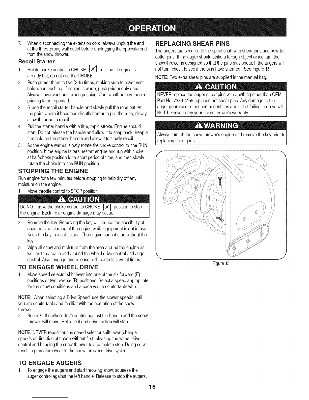
REPLACING SHEAR PINS
Theaugersare securedtothespiralshaftwith shearpinsandbow-tie
cotterpins.If theaugershouldstrikeaforeignobjectoricejam,the
snowthrowerisdesignedsothatthe pinsmayshear.Iftheaugerswill
notturn,checktosee ifthepinshavesheared. SeeFigure15.
NOTE:Twoextrashearpinsaresuppliedin themanualbag.
NEVERreplacetheaugershearpins withanythingotherthanOEM
PartNo.738-04155replacementshearpins.Anydamagetothe
augergearboxorothercomponentsas a resultoffailingtodo sowill
NOTbecoveredbyyour snowthrower'swarranty.
Alwaysturnoffthesnowthrower'sengineand removethekeypriorto
replacingshearpins.
DoNOTmovethe chokecontroltoCHOKE 14¢1positionto stop
theengine.Backfireorenginedamagemayoccur.
2. Removethe key.Removingthekeywillreducethepossibilityof
unauthorizedstartingofthe enginewhileequipmentisnot inuse.
Keepthekeyina safeplace.Theenginecannotstart withoutthe
key.
3. Wipeallsnowandmoisturefromtheareaaroundtheengineas
wellas theareainandaroundthewheeldrivecontrolandauger
control.Also,engageandreleasebothcontrolsseveraltimes.
TO ENGAGE WHEEL DRIVE
1. Movespeedselectorshiftleverintooneofthesixforward(F)
positionsortwo reverse(R)positions.Selectaspeedappropriate
forthe snowconditionsanda paceyou'recomfortablewith.
NOTE: WhenselectingaDriveSpeed,usetheslowerspeedsuntil
youarecomfortableandfamiliarwiththe operationof thesnow
thrower.
2. Squeezethewheeldrivecontrolagainstthehandleandthesnow
throwerwillmove.Releaseitanddrive motionwillstop.
NOTE:NEVERrepositionthespeedselectorshiftlever(change
speedsordirectionoftravel)withoutfirstreleasingthewheeldrive
controlandbringingthesnowthrowerto a completestop.Doingsowill
resultinprematurewearto thesnowthrower'sdrive system.
Figure15
TO ENGAGE AUGERS
1. Toengagetheaugersandstart throwingsnow,squeezethe
augercontrolagainsttheleft handle.Releaseto stoptheaugers.
16
Page 17
MAINTENANCE SCHEDULE
Beforeperforminganytypeofmaintenance/service,disengageall
controlsandstoptheengine.Waituntilallmovingpartshavecometo a
completestop.Removethekeytopreventunintendedstarting.Always
wearsafetyglassesduringoperationorwhileperforminganyadjustments
orrepairs.
EachUse
1. Engineoillevel
2. Looseormissinghardware
3. Unitandengine.
1st5 - 8hours
25 hours
1. Engineoil
1. Engineoi11-
2. Controllinkagesand pivots
50 hours
Annuallyor100hours
1. Engineoil
1. Sparkplug
BeforeStorage 1. Fuelsystem
1. Check
2. Tightenor replace
3. Clean
1. Change
1. Change
2. Lubewithlightoil
1. Change
1. Cleanand re-gap,orelse replace
1. Runengineuntilit stopsfromlackof
Underheavyloador inhightemperatures
Followthemaintenanceschedulegivenbelow.Thischartdescribes
serviceguidelinesonly.UsetheServiceLogcolumnto keeptrackof
completedmaintenancetasks.To locate the nearest SearsService
Centeror toscheduleservice,simplycontactSearsat
1-800-4-MY-HOME®.
= =
withnewplug.
fueloradda gasolineadditivetothe
gasin thetank.
ENGINE MAINTENANCE
Checking Engine Oil
Beforelubricating,repairing,or inspecting,disengageallcontrolsand
stopengine.Waituntilallmovingpartshavecometoa completestop.
Removethekeytopreventunintendedfiringoftheengine.
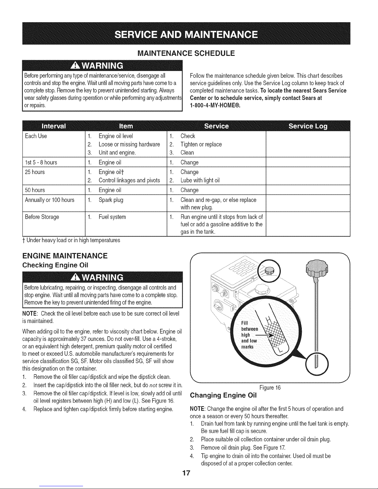
NOTE: Checktheoillevelbeforeeachuseto besurecorrectoil level
ismaintained.
Whenaddingoilto theengine,referto viscositychart below.Engineoil
capacityisapproximately37 ounces.Donotover-fill.Usea4-stroke,
oran equivalenthighdetergent,premiumqualitymotoroilcertified
tomeetorexceedU.S.automobilemanufacturer'srequirementsfor
serviceclassificationSG,SRMotoroilsclassifiedSG,SFwillshow
thisdesignationonthecontainer.
1. Removetheoil fillercap/dipstickandwipethe dipstickclean.
2. Insertthe cap/dipstickintotheoilfiller neck,butdo not screwit in.
3. Removetheoil fillercap/dipstick.Iflevelislow,slowlyadd oiluntil
oil levelregistersbetweenhigh(H)andlow (L). SeeFigure16.
4. Replaceandtightencap/dipstickfirmlybeforestartingengine.
J
Figure16
Changing Engine Oil
NOTE:Changetheengineoil afterthefirst5 hoursofoperationand
oncea seasonor every50hoursthereafter.
1. Drainfuelfromtankbyrunningengineuntilthefueltankis empty.
Besurefuel fillcapis secure.
2. Placesuitableoilcollectioncontainerunderoil drainplug.
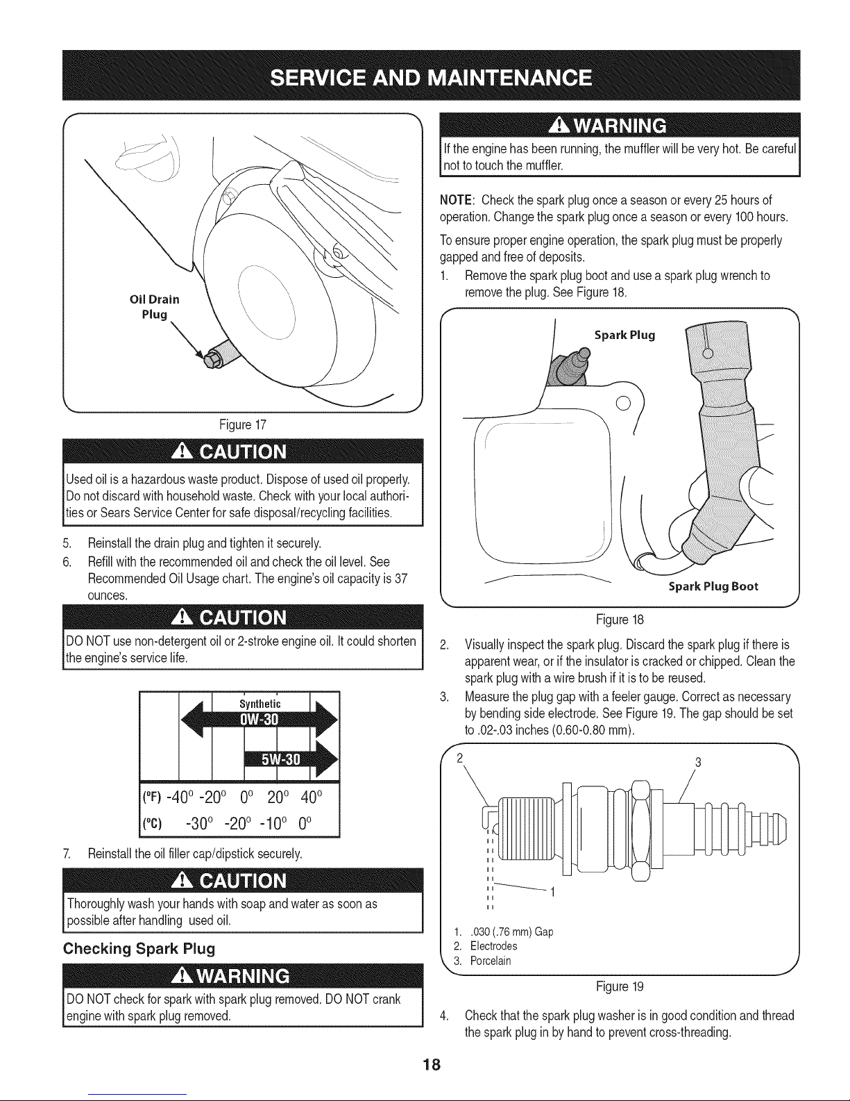
3. Removeoil drainplug.SeeFigure17.
4. Tipenginetodrainoil intothecontainer.Usedoil mustbe
disposedofat a propercollectioncenter.
17
Page 18
f
Oil Drain
Plug
Figure17
Usedoil isa hazardouswasteproduct.Disposeof usedoil properly.
Donotdiscardwith householdwaste.Checkwithyourlocalauthori-
tiesor SearsServiceCenterforsafedisposal/recyclingfacilities.
Iftheenginehas beenrunning,themufflerwillbeveryhot.Becareful
notto touchthemuffler.
NOTE: Checkthesparkplugoncea seasonor every25hoursof
operation.Changethe sparkplugoncea seasonorevery100hours.
Toensureproperengineoperation,the sparkplugmustbeproperly
gappedandfreeof deposits.
1. Removethesparkplugbootandusea sparkplugwrenchto
removetheplug.SeeFigure18.
Spark Plug
.
Reinstallthedrainplugandtightenit securely.
6.
Refillwiththerecommendedoilandcheckthe oil level.See
RecommendedOil Usage chart. The engine's oilcapacity is 37
ounces.
DONOTuse non-detergentoilor 2-strokeengineoil.Itcouldshorten
theengine'sservicelife.
(°F}=40o =20o 0o 200 400
(°c) -30° -20° -10° 0°
7. Reinstalltheoilfillercap/dipsticksecurely.
Thoroughlywashyour handswithsoapandwateras soonas
possibleafterhandling usedoil.
Checking Spark Plug
DONOTcheckforsparkwithsparkplugremoved.DONOTcrank
enginewithsparkplugremoved.
Figure18
2. Visuallyinspectthe sparkplug. Discardthe sparkplugifthereis
apparentwear,orif theinsulatoriscrackedorchipped.Cleanthe
sparkplugwithawirebrushifit is tobe reused.
3. Measurethepluggapwitha feelergauge.Correctasnecessary
bybendingsideelectrode.SeeFigure19.Thegap shouldbeset
to .02-.03inches(0.60-0.80ram).
,'2 3
1..030 (.76 mm) Gap
2. Electrodes
k"_i Porcelain
Figure19
4. Checkthatthesparkplugwasheris ingoodconditionandthread
thesparkpluginby handto preventcross-threading.
18
Page 19
5. Afterthe sparkplugisseated,tightenwitha sparkplugwrenchto
compressthewasher.
NOTE:Wheninstallinga newsparkplug,tighten1/2-turnafterthe
sparkplugseatsto compressthewasher.Whenreinstallinga used
sparkplug,tighten1/8-to 1/4-turnafterthe sparkplugseatsto
compressthewasher.
hotandcan ine.
CARBURETOR ADJUSTMENT
Thecarburetoris notuseradjustable.ContactSearsParts& Repairfor
adjustment.
LUBRICATION
Drive and Shifting Mechanism
Atleastoncea seasonorafterevery25 hoursofoperation,remove
rearcover.Lubricateall chains,sprockets,gears,bearings,shafts,and
theshiftingmechanism.Useengineoilora spraylubricant.Referto
Figure20.
f
Chute Directional Control
Onceaseason,lubricatetheeyeboltbushingandthespiralwith3-in-1
oil.
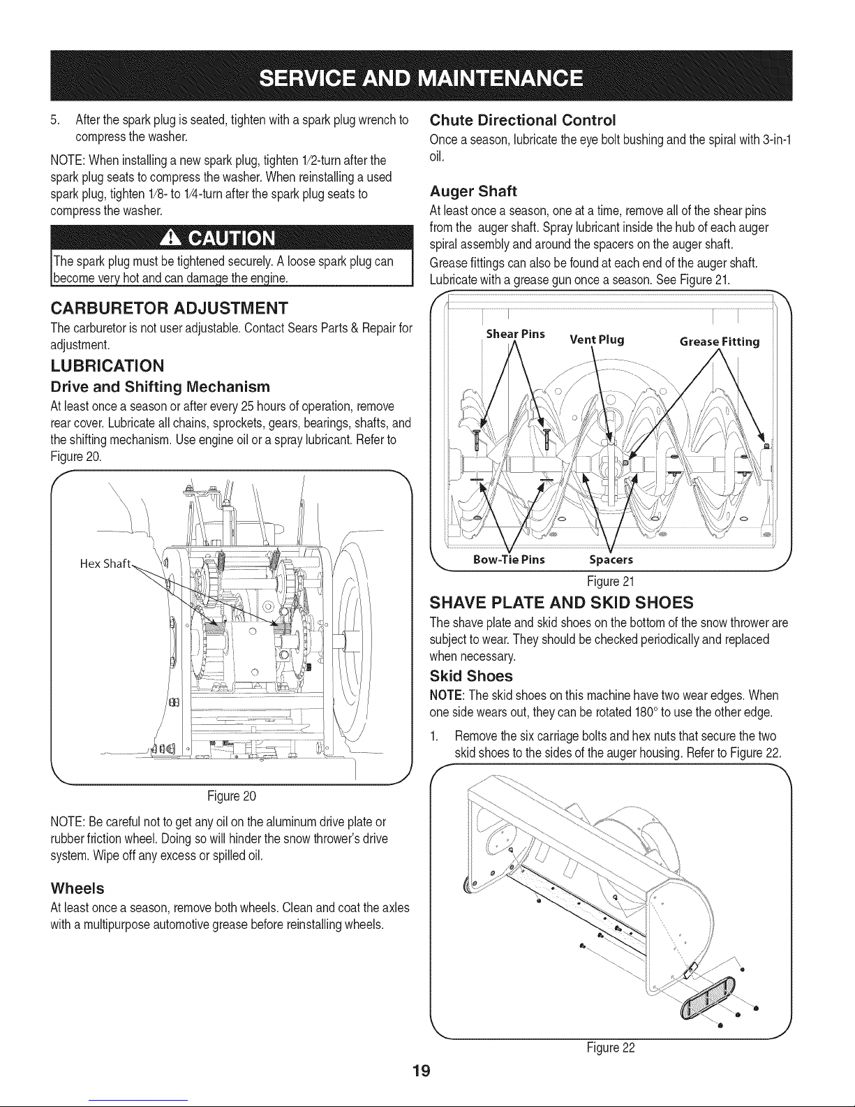
Auger Shaft
At leastoncea season,oneata time,removeallof theshearpins
fromthe augershaft.Spraylubricantinsidethehubof eachauger
spiralassemblyandaroundthe spacersontheaugershaft.
Greasefittingscan alsobefoundateachendofthe augershaft.
Lubricatewitha greasegunoncea season.SeeFigure21.
f ...............
Figure20
NOTE:Becarefulnottoget anyoilon thealuminumdriveplateor
rubberfrictionwheel.Doingsowill hinderthesnowthrower'sdrive
system.Wipeoff anyexcessor spilledoil.
Wheels
Atleastoncea season,removebothwheels.Cleanandcoattheaxles
witha multipurposeautomotivegreasebeforereinstallingwheels.
Bow=Tie Pins S pacers
Figure21
SHAVE PLATE AND SKID SHOES
Theshaveplateandskidshoeson thebottomofthesnowthrowerare
subjectto wear.Theyshouldbecheckedperiodicallyand replaced
whennecessary.
Skid Shoes
NOTE:The skidshoesonthis machinehavetwowearedges.When
one sidewearsout,theycanberotated1800touse theotheredge.
1. Removethesixcarriageboltsandhexnutsthatsecurethetwo
skidshoestothe sidesoftheaugerhousing.Referto Figure22.
J
Figure22
19
Page 20

2. Positionthenew skidshoesandsecurewiththe carriagebolts
andhexnuts.Makecertaintheskidshoesare adjustedto be
level.
Shave Plate
1. Removethehexnutsandcarriageboltsthatsecuretheshave
plateto thebottomofthehousing.
2. Removetherearmosthexnutand carriageboltsecuringtheback
ofeachskidshoeto thesidesofthehousing.Loosenthefour
remaininghexnutssecuringtheskidshoes.
3. Slidetheshaveplateoutofthe off-setslotat thebottomofthe
housing,andfrombetweentheskidshoesandside panelsofthe
housing.
4. Withthemountingholestowardthebackofthe unit,slidethenew
shaveplateinto positionandsecurewiththefastenersremoved
previously.
ADJUSTMENTS
Speed selector Rod
If thefull rangeofspeeds(forwardandreverse)cannotbe achieved,
referto Figure20totheleftandadjustthe speedselector rodas
follows:
1. Lookingunderneaththehandlepanel,notewhichofthethree
holesin thespeedselectorlevertheferruleisinsertedinto.Also
notethe directionof insertion.Thenremovetheinternalcotterpin
andflatwasherfromtheferruleandwithdrawtheferrulefromthe
speedselector lever.SeeFigure23.
Chute Control
Thedistancesnowisthrowncanbe adjustedbyadjustingthe angleof
thechuteassembly.Refertothe Operationsectionforinstructions.
Theremotechutecontrolcableshavebeenpre-adjustedatthefactory.
Movethe remotechuteleveron thecontrolpanelforwardtopivotthe
upperchutedown;movetheleverrearwardtopivottheupperchute
up.
Wheel drive control
Referto theAdjustmentsectionof theAssemblyinstructionsto adjust
thewheeldrivecontrol.Tofurtherchecktheadjustment,proceedas
follows:
1. Withthesnowthrowertippedforward(becertaintorunthe
fueltankdry beforetippingtheunitforward),removetheframe
coverunderneaththesnowthrowerbyremovingthe self-tapping
screws.
2. Locatetheopeningbetweentheaxle supportbracketand
thefrontframesupport(See Figure24).Lookingthroughthis
opening,withthe wheeldrivecontrolreleased,theremustbe
clearancebetweenthe frictionwheelandthe driveplateinall
positionsofthespeedselector lever.
3. Withthewheeldrivecontrolengaged,thefrictionwheelmust
contactthedriveplate.SeeFigure24.
\ \
\
Ferrule
\ \
Figure23
2. Placespeedselectorleverin sixth(6) positionorfastestforward
speed.
3. Pushspeedselector rodand speedselectorarmassemblydown
sharplyasfaras itwillgoto putthe driveintothefastestforward
position.
4. Asnecessary,rotatetheferruleupordownthespeedselector
roduntilthe ferrulelinesup withtheholefromwhichitwasearlier
removed.See Figure23.
5. Fromthedirectionnotedearlier,inserttheferruleintotheproperhole.
6. Reinstallthewasherandtheinternalcotterpin.
Friction
Wheel
Figure24
4. Ifthereisnofrictionwheelclearance,or thefrictionwheeldoes
notsolidlycontactthe driveplate,re-adjustthelocknut onthe
lowerendof thedrivecablefollowingtheinstructionsinthe
Assemblysection.
5. Reassembletheframecover.
2O
Page 21
Chute Bracket
Ifthe spiralatthebottomofthechutedirectionalcontrolis notfully
engagingwiththechuteassembly,thechutebracketcanbeadjusted.
Todo so:
1. Loosenthetwonutswhichsecurethechutebracketandreposi-
tionit slightly.SeeFigure25.
2. Retightenthenuts.
/
Figure25
2. Removethe plasticbeltcover,locatedneartheengine,by remov-
ing thethreeself-tappingscrewsthatsecureit.See Figure27.
\
Figure27
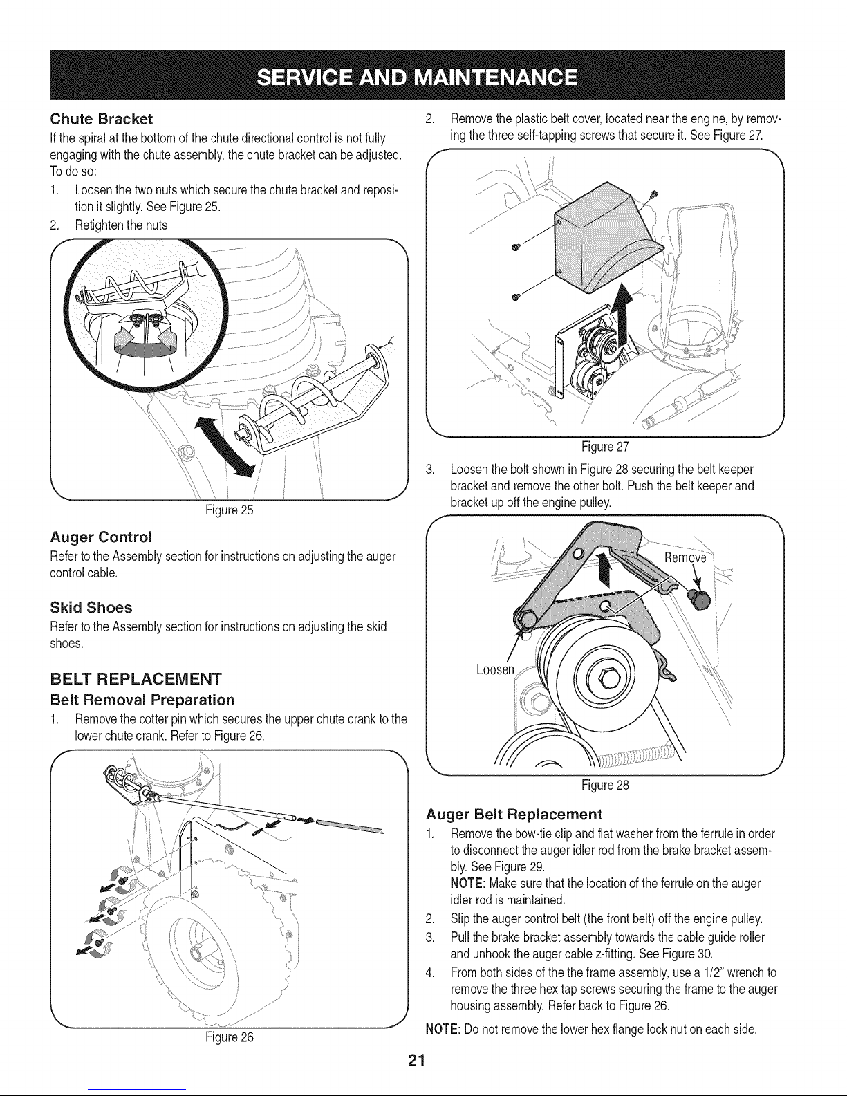
3. LoosentheboltshowninFigure28securingthe beltkeeper
bracketandremovetheotherbolt.Pushthebelt keeperand
bracketupoff theenginepulley.
Auger Control
Refertothe Assemblysectionforinstructionsonadjustingtheauger
controlcable.
Skid Shoes
Refertothe Assemblysectionforinstructionsonadjustingthe skid
shoes.
BELT REPLACEMENT
Belt Removal Preparation
1. Removethecotterpinwhichsecurestheupperchutecranktothe
lowerchutecrank.Referto Figure26.
Figure26
Figure28
Auger Belt Replacement
1. Removethebow-tieclipandflatwasherfromtheferruleinorder
todisconnecttheaugeridlerrodfromthe brakebracketassem-
bly.SeeFigure29.
NOTE:Makesurethatthelocationoftheferruleontheauger
idlerrodismaintained.
2. Sliptheaugercontrolbelt(the frontbelt)offtheenginepulley.
3. Pullthebrakebracketassemblytowardsthecableguideroller
and unhooktheaugercablez-fitting.SeeFigure30.
4. Frombothsidesofthetheframeassembly,usea 1/2"wrenchto
removethethreehextap screwssecuringtheframeto theauger
housingassembly.ReferbacktoFigure26.
NOTE:Donotremovethelowerhexflangelocknut oneach side.
21
Page 22
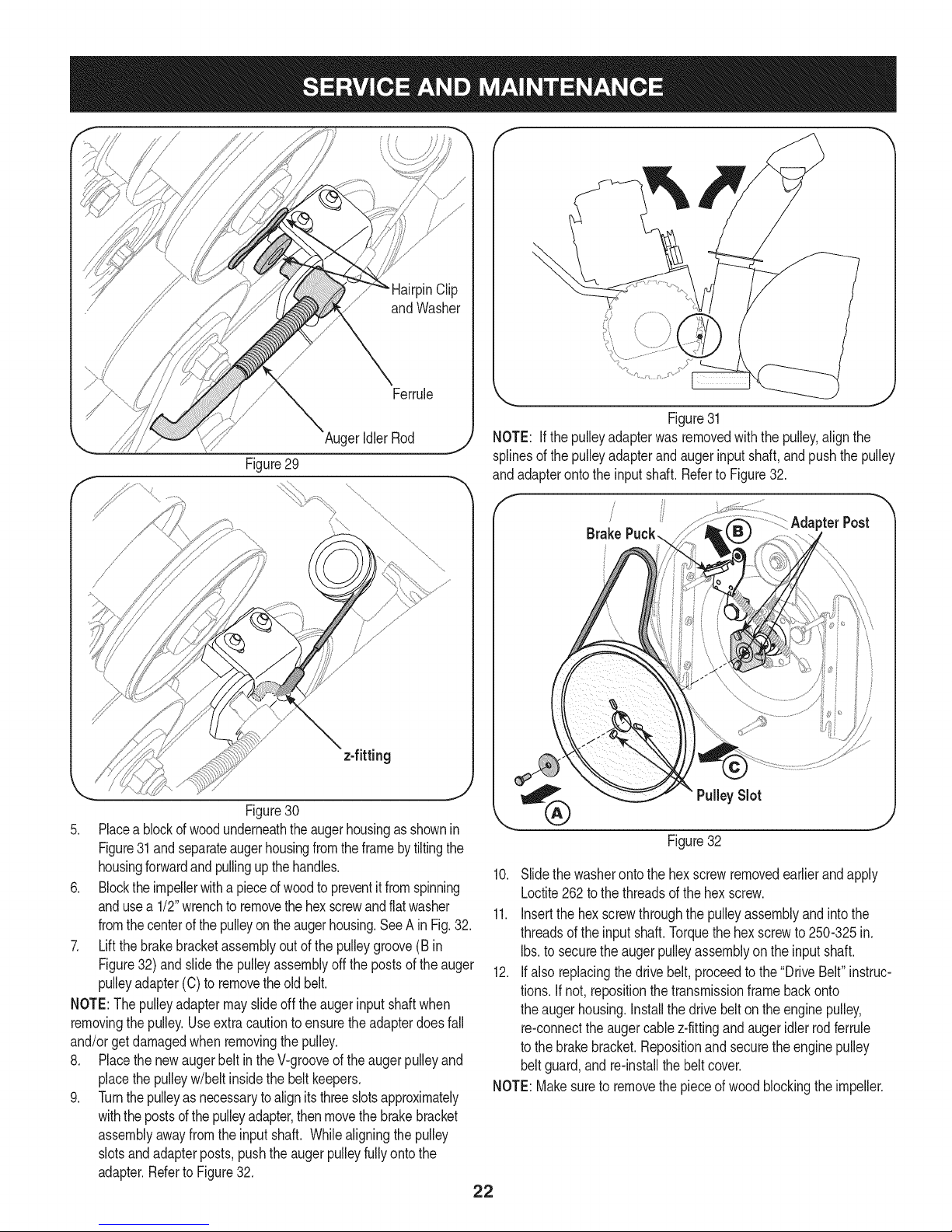
Figure29
\
AugerIdlerRod
Figure31
NOTE: Ifthepulleyadapterwasremovedwiththepulley,alignthe
splinesof thepulleyadapterandaugerinputshaft,andpushthepulley
andadapterontotheinputshaft.RefertoFigure32.
/
/ pterPost
Brake
Figure30
5. Placeablockofwoodunderneaththeaugerhousingasshownin
Figure31andseparateaugerhousingfromtheframebytiltingthe
housingforwardandpullingupthehandles.
6. Blocktheimpellerwitha pieceofwoodtopreventitfromspinning
andusea 1/2"wrenchtoremovethehexscrewandflatwasher
fromthecenterof thepulleyontheaugerhousing.SeeA in Fig.32.
7. Liftthebrakebracketassemblyoutof thepulleygroove(B in
Figure32)andslidethepulleyassemblyoffthe postsof theauger
pulleyadapter(C)to removetheoldbelt.
NOTE:Thepulleyadaptermayslideoff theaugerinputshaftwhen
removingthepulley.Useextracautionto ensuretheadapterdoesfall
and/orget damagedwhenremovingthepulley.
8. Placethe newaugerbeltinthe V-grooveoftheaugerpulleyand
placethe pulleyw/beltinsidethebeltkeepers.
9. Turnthepulleyasnecessarytoalignitsthreeslotsapproximately
withthepostsofthe pulleyadapter,thenmovethe brakebracket
assemblyawayfromtheinputshaft. Whilealigningthepulley
slotsandadapterposts,pushthe augerpulleyfullyontothe
adapter.Referto Figure32.
PulleySlot
Figure32
10. Slidethewasherontothe hexscrewremovedearlierandapply
Loctite262to thethreadsofthe hexscrew.
11. Insertthe hexscrewthroughthepulleyassemblyandintothe
threadsofthe inputshaft.Torquethehexscrewto 250-325in.
Ibs.to securetheaugerpulleyassemblyonthe inputshaft.
12. Ifalsoreplacingthedrivebelt,proceedtothe"DriveBelt"instruc-
tions.Ifnot, repositionthetransmissionframebackonto
theaugerhousing.Installthedrivebelton theenginepulley,
re-connecttheaugercablez-fittingandaugeridlerrodferrule
tothe brakebracket.Repositionandsecuretheenginepulley
beltguard,andre-installthebelt cover.
NOTE:Makesuretoremovethepieceof woodblockingtheimpeller.
22
Page 23
Checktheaugerdrivebeltadjustment.Withthe augerclutchlever
inthedisengagedposition,thetopsurfaceofthe newbeltshouldbe
evenwiththeoutsidediameterofthe pulley.
Toadjust,disconnectferrulefrombrakebracketassembly.Thread
ferrulein(towardsidler)toincreasetensiononbelt,orout to decrease
belttension.
NOTE:Thebrakepuckmustalwaysbefirmly seatedinthepulley
groovewhenaugercontrolisdisengaged.
IMPORTANT:Repeatthe"AugerDriveControlTest"fromtheAs-
semblysectionbeforeoperatingsnowthrower.
Drive Belt Replacement
If notalreadydone,removethe augerdrivebeltfromthefrontpulleyof
theenginedoublepulley.Referto "AugerBeltReplacement"instruc-
tionsintheprevioussub-section.
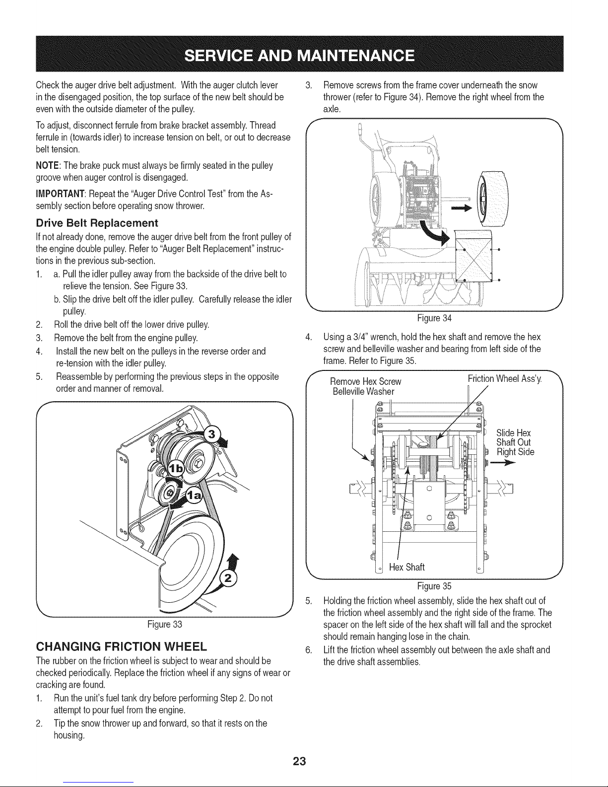
1. a.Pulltheidlerpulleyawayfromthebacksideofthe drivebeltto
relievethetension.SeeFigure33.
b.Slipthe drivebeltoffthe idlerpulley. Carefullyreleasetheidler
pulley.
2. Rollthedrive beltoffthelowerdrivepulley.
3. Removethebeltfromtheenginepulley.
4. Installthenewbelt onthepulleysinthe reverseorderand
re-tensionwiththeidlerpulley.
5. Reassemblebyperformingthepreviousstepsintheopposite
orderandmannerof removal.
f
3. Removescrewsfromtheframecoverunderneaththesnow
thrower(referto Figure34).Removethe rightwheelfromthe
axle.
f
e
Figure34
.
Usinga3/4"wrench,holdthehexshaftand removethehex
screwandbellevillewasherandbearingfromleftsideof the
frame.Referto Figure35.
f
RemoveHexScrew
FrictionWheelAss'y.
BellevilleWasher
J
J
Figure33
CHANGING FRICTION WHEEL
Therubberonthe frictionwheelissubjecttowearandshouldbe
checkedperiodically.Replacethefrictionwheelifanysignsof wearor
crackingarefound.
1. Runthe unit'sfueltankdrybeforeperformingStep2.Do not
attempttopourfuel fromtheengine.
2. Tipthe snowthrowerupandforward,sothatit restsonthe
housing.
SlideHex
ShaftOut
RightSide
.._
HexShaft
Figure35
5. Holdingthefrictionwheelassembly,slidethehexshaftoutof
thefrictionwheelassemblyandthe rightsideoftheframe.The
spaceron theleftsideof the hexshaftwillfallandthesprocket
shouldremainhangingloseinthe chain.
6. Liftthefrictionwheelassemblyoutbetweentheaxleshaft and
thedriveshaftassemblies.
23
Page 24

7. Removefourscrewssecuringthefrictionwheelto the hub 12.
assembly(referto Figure36).Discardoldfrictionwheel.
Figure36
8. Reassemblethenewfrictionwheelontothehubassembly,
tighteningthe fourscrewsin rotationandwithequalforce.Itis
importanttoassemblethefrictionwheelsymmetricallyforproper
functioning.
9. Repositionthefrictionwheelassemblyin the snowthrowerframe.
Insertthe pinfromthespeedselectorarmassemblyintothe
frictionwheelassemblyandholdassemblyin position.Referto
Figure37.
13.
14. Slidethebearingontothe leftendof thehexshaftandpressinto
15. Placethebellevillewasher(roundedside towardhead)ontothe
16. Graduallytightenthe hexscrewtofullyseatthebearingsineach
17. Positiontheframecoveron the bottomoftheframeand secure
Slidethespacerontotheendof thehexshaft.
Alignthebearingonthe rightendof thehexshaftwiththe hole
intherightsideof theframe,thenpushthehexshafttotheleft
intopositioninthe frame.
theholeon theleft sidetheframe.
hexscrewremovedearlier,andinsertthescrewinto thethreaded
holeofthe hexshaft.
sideof theframeandtosecurethehex shaft.
withtheself-tappingscrews.Pivotthe snowthrowerdownto it
normaloperatingposition.
10. Slidethehexshaftthroughthe rightsideofthe frametowardthe
left sideandthroughthefrictionwheelassembly.
11. Aftermakingcertainthatthechainis on boththelargeandthe
smallsprocket,alignthe hexshaftwiththe hexhubofthesmall
sprocket,andslidetheshaftthroughthesprocket.
NOTE:Ifthe sprocketfellfromthesnowthrowerwhileremovingthe
hexshaft,placethesprocketonthechain.Realignthesprocketon the
chainwiththe hexhubfacingthe rightsideof unit.Positionthehex
hubofthe sprockettowardthefrictionwheelwhenslidingthesprocket
ontothe hexshaft.
24
Page 25

Ifthe snowthrowerwillnotbe usedfor30 daysorlonger,orifit is theendofthesnowseasonwhenthelastpossibilityof snowisgone,the
equipmentneedstobestoredproperly.Followstorageinstructionsbelowto ensuretopperformancefromthesnowthrowerformanymoreyears.
PREPARING ENGINE
Enginesstoredover30daysneedtobedrainedof fueltoprevent
deteriorationandgumfromforminginfuelsystemoronessential
carburetorparts.If thegasolineinyourenginedeterioratesduring
storage,youmayneedto havethecarburetor,andotherfuelsystem
components,servicedorreplaced.
1. Removeall fuelfromtank by runningengineuntilitstops.Donot
attempttopourfuel fromtheengine.
2. Changetheengineoil.
3. Removesparkplugandpourapproximately1oz.(30 rnl)ofclean
engineoil intothecylinder.Pullthe recoilstarterseveraltimesto
distributetheoil,and reinstallthe sparkplug.
4. Cleandebrisfromaroundengine,andunder,around,andbehind
muffler.Applya lightfilmof oilon anyareasthatare susceptible
torust.
• Storeina clean,dry andwellventilatedareaawayfromanyap-
pliancethatoperateswithaflameor pilotlight,suchasa furnace,
waterheater,or clothesdryer.Avoidanyareawitha spark
producingelectricmotor,or wherepowertoolsareoperated.
Neverstoresnowthrowerwithfuelintank indoorsorinpoorlyventi-
latedareas,wherefuelfumesmayreachanopenflame,sparkor pilol
lightas ona furnace,waterheater,clothesdryerorgasappliance.
PREPARING SNOW THROWER
Whenstoringthe snowthrowerin anunventilatedormetalstor-
age shed,careshouldbetakentorustprooftheequipment.Using
a lightoilor silicone,coattheequipment,especiallyanychains,
springs,bearingsandcables.
• Removealldirt fromexteriorofengineandequipment.
• Followlubricationrecommendations.
• Storeequipmentin a clean,dryarea.
• If possible,avoidstorageareaswithhighhumidity.
• Keepthe enginelevelinstorage.Tiltingcancausefueloroil
leakage.
26
Page 26

Enginefailstostart
Enginerunningerratically/
inconsistentRPM(huntingor
surging)
Excessivevibration
Lossofpower
Unitfailstopropelitself
Unitfailstodischargesnow
1. Chokecontrolnotin CHOKEposition.
2. Sparkplugwiredisconnected.
3. Faultysparkplug.
4. Fueltankemptyor stalefuel.
5. Enginenotprimed.
6. Keynot inserted.
7. Extensioncordnotconnected(when
usingelectricstartbutton,on modelsso
equipped).
1. EnginerunningonCHOKE.
2. Stalefuel.
3. Waterordirt infuelsystem.
4. Over-governedengine.
1. Loosepartsor damagedauger.
1. Sparkplugwireloose.
2. Gascap ventholeplugged.
1. Drivecableinneedof adjustment.
2. Drivebeltlooseor damaged.
3. Wornfrictionwheel.
1. Chuteassemblyclogged.
2. Foreignobjectlodgedin auger.
3. Augercablein needof adjustment.
4. Augerbeltlooseordamaged.
5. Shearpin(s)sheared.
1. Movechokecontrolto CHOKEposition.
2. Connectwireto sparkplug.
3. Clean,adjustgap,or replace.
4. Filltankwithclean,freshgasoline.
5. Primeengineasinstructedin the OperationSection.
6. Insertkeyfullyintothe switch.
7. Connectoneendof the extensioncordtotheelectric
starteroutletandthe otherendtoa three-prong
120-volt,grounded,ACoutlet.
1. Movechokecontrolto RUNposition.
2. Filltankwithclean,freshgasoline.
3. Drainfueltank.Refillwithfreshfuel.
4. ContactyourSearsParts& RepairCenter.
1. Stopengineimmediatelyand disconnectsparkplug
wire.Tightenall boltsand nuts.Ifvibrationcontinues,
haveunit servicedbya SearsParts& RepairCenter.
1. Connectandtightensparkplugwire.
2. Removeiceand snowfromgascap. Becertainvent
holeisclear.
1. Adjustdrivecontrolcable.Referto Serviceand
Maintenancesection.
2. Replacedrivebelt.RefertoServiceand Mainte-
nancesection.
3. Changefrictionwheelorcontactyour SearsParts&
RepairCenter.
1. Stopengineimmediatelyand disconnectsparkplug
wire.Cleanchuteassemblyandinsideofauger
housingwithclean-outtoolor a stick.
2. Stopengineimmediatelyand disconnectsparkplug
wire.Removeobjectfromaugerwithclean-outtool
ora stick.
3. Adjustaugercontrolcable.RefertoAssembly
section.
4. Replaceaugerbelt.RefertoServiceand Mainte-
nancesection.
5. Replacewith newshearpin(s).
Chutefailstoeasilyrotate180 1. Unassemblechutecontrolandreassembleas
1. Chuteassembledincorrectly.
degrees directedintheAssemblysection.
27
Page 27

27
Page 28

Craftsman Snow Thrower Model 247.88835
19
48
47
43
28
Page 29

Craftsman Snow Thrower IViodel 247.88835
D = " _ 0
618-0281A BracketAssy,AugerBrake
2. 684-0090B-0637 Impellar,16"
3. 731-2643 Tool,Cleanout
4. 710-0376 Scr,HexCap,5/16-18x 1.00
5. 710-04484 Screw,5/16-18x .750
6. 710-0451 Screw,Carriage,5/16-18x .75
7. 710-04606A Screw,5/16-18x .4300
8. 710-1245B Screw,5/16-24x .875
9. 911-0677 Ferrule
10. 712-04063 Nut,FlngeLk,5/16-18
11. 712-04065 Nut,FigLk,3/8-16
12. 914-0135 Key,Woodruff,I/4x3/4
13. 714-04040 Pin,BowtieCotter
14. 915-0118 Pin,Spirol,5/16x 1.75
15. J725-0157 JTie,Cable
16. 926-04012 Nut,Push
17. 731-1696B Adapter,Chute,6"
18. 732-0858 Spring,Extension
19. 936-0159 Washer,.349x .879x .063
20. 736-0174 Washer,.625x .885x .015
21. 736-0505 Washer,Flat, .34x 1.50x .150
22. 936-3008 Washer,.344 x.75x .12
23. 736-3046A Washer,1.01x 1.86x .06
24. 731-2635 Clip,Mounting
25. 938-0281 Screw,Shoulder,.625x .17
26. 738-04155 Pin,Shear,.25x 1.75
27. 741-0192 Bearing,Flangew/Flats
28. 941-04024 Bearing,SelfAligning
29. 747-0980A Rod,AugerIdler
30. 748-04067A Pulley,Adapter,.75Dia.
31. 950-04020 Spacer,1.004x 1.375x .25
32. 756-04244A Pulley,AugerDrive,10.0
33. 790-00264A-0637 Bracket,GearBoxSupport
34. 05244B Housing,Bearing
D = O
05845C Housing,Bearing
36. 918-04515 GearBoxAssembly,Auger
37. 684-04151-4028 SpiralAssy,LH
38. 684-04152-4028 SpiralAssy,RH
39. 684-04214-0691 Housing,Auger- 33"
40. 731-05162 Spacer,1.0x 1.5x 2
41. 731-05163 Spacer,1.0x 1.5x 1
42. 938-04158 Axle,Spiral,33"
43. 741-0494 Bushing,Flange,1.051x 1.16
44. 784-5714B-0637 ShavePlate
45. 710-0389 Bolt,Carriage,3/8-16x .750
46. 710-3168 Bolt,Carriage,3/8-16x 1.0
47. 784-5697-0637 Shoe,Skid
48. 790-00181-0637 DriftCutter
49. 929-0071 ExtensionCord,110V
50. 918-0246 HsgAssyAugerRH(Inc.65 &66)
51. 918-0247 HsgAssyAugerLH(Inc.65 &66)
52. 710-1260A Screw,LD,5/16-18x.750
53. 711-04714 Shf,Drive,Auger
54. 914-0126 Key,HiPro,3/16x3/4
55. 716-0111 Ext,Ret,Ring
56. 917-0299 Gear,Worm,DblThread
57. 917-1425 Gear,Worm,LH
58. 921-0145 Seal,Oil
59. 721-0325 Plug
60. 936-0266 Washer,Flat, 1.52IDx2.00D
61. 936-0291 Washer,Flat,.88IDx .38 OD
62. 738-0275 Shf,Gear,Worm
63. 741-0184 Brg,Thrust
64. 941-0217 Sleeve
65. 921-0146 OilSeal
66. 741-0670 FlangeBearing
67. 954-04194A V Belt,4Lx44.60Lg.
68. 737-3000 LubeFitting,3/16 #70
29
Page 30

Craftsman Snow Thrower IViodel 247.88835
78
77
\
5O
27
3O
53
\23
43/
38
21
15
4O
/
i
i
i
i
i
/
3O
Page 31

D _ O O
684-04308A ChuteCrankAssembly
2 .684-04350 _ JointBlockAssembly
3 710-0276 Screw,Carriage,5/16-18x 1.0
4 710-04682 Screw,Hex,3/8-16x2.00 Lock,Gr5
5 710-0572 Screw,Carriage,5/16-18x2.5
6 710-3118 Screw,Hex,3/8-16x 1.0Lock,Gr5
7 712-04063 FlangeLockNut,5/16-18
8 912-3010 HexNut,5/16-18
9 914-0101 InternalCotterPin
10 914-0104 InternalCotterPin
11 715-04095 SpringPin
12 720-0201A Knob,Crank
13 720-04072 Knob,WingNut,5/16-18
14 926-0100 Cap,Push,3/8
15 735-0234 Grommet,Rubber
16 736-0105 Washer,Bel,.375x .87x .063
17 936-0159 Washer,Fiat,.349x .879.063
18 936-0185 Washer,.375x .738x .063
19 736-0242 Washer,Belleville,.34x .872x.06
20 941-0475 PlasticBushing,.380I.D.
21 .747-04747 _EyeBolt
22 747-04925A-0637 ChuteRod
23 749-04309-0691 Handle,Upper- LH
24 749-04310-0691 Handle,Upper- RH
25 749-0991-0691 Handle,Lower
26 790-00329-0637 ChuteCrankBracket
27 716-04036 Ring,Retainer
28 725-0157 CableTie
29 731-06113 Trigger
30 738-04126 Pin,3/16
31 710-04022 HexHeadScrew,MB1.25
32 732-04677 CableGuide
33 i 936-0264 FiatWasher,.330x .630x .0635
34 984-04230 2-WayChuteControFMAssy
35 710-04187 Hi-LoScrew,1/4-15x0.5
36 710-0458 Bolt,Carriage,5/16-18x 1.75
37 710-0597 Screw,1/4-20x 1.00
38 710-0895 Hi-LoScrew,1/4-15x .75
39 712-04064 FlangeLockNut,1/4-20
40 731-0846C UpperChute
41 731-0851A Chute,FlangeKeeper
D _ O
731-0903E LowerChute
43 731-1313C ChuteTiltCableGuide
44 936-0231 FiatWasher
45 784-5594-0637 CableBracket
46 631-04133A HandleClutchLock- LH
47 631-04134B HandleClutchLock- RH
48 631-04187P HandlePanel
49 646-0012 CableAssembly,Auger/Drive
746-0952 Cable,Clutch
732-0184 Spring,Extension
50 684-04111B HandleEngageAssy- LH
51 684-04112B HandleEngageAssy- RH
52 684-04250 RodAss'y,ClutchLockPivot
53 710-04326 Screw,#8-16x0.50
54 710-04586 Screw,1/4-20x 1.625
55 710-0837 AB Screw,#10-16
56 710-1233 Screw,#10-24x0.375
57 710-3069 Screw,1/4-20x.375
58 712-04081A ShoulderNut,1/4-20
59 720-04039 ShiftKnob
60 925-04213 Lamp
61 725-04216B WiringHarness(NotShown)
62 725-04393 Htd.HandGripon/offSwitch
63 925-1649 LightSocket
64 725-1757 HeatedHandGrip
65 731-04894D LockPlate
66 731-04896B ClutchLockCam
67 732-0193 CompressionSpring
68 732-04219C ClutchLockSpring
69 732-04238 TorsionSpring
70 935-0199A RubberBumper
71 936-0267 FiatWasher,.385x .87x .06
72 738-04125 ShoulderScrew
73 738-04348 ShoulderScrew,1/4-20x 1.345
74 746-04341 SpeedSelectorCable
75 790-00248B-0637 PanelBracket
76 790-00281B-0637 Shift Lever
77 731-05324 LensPanel
78 777X41804 ReflectorLabel
79 746-04338 Cable,ChuteTilt
31
Page 32

Craftsman Snow Thrower Model 247.88835
106
91
104
23._
102
100
103
92
"93 78
...........
ii / i
108
44 21_
5O
45
36
14
/7
18
18
77
27
73
33
67
17
28
25 32
32
56
19 55
72
4O
24
11
31 54
_/32
111 10
32
Page 33

Craftsman Snow Thrower IViodel 247.88835
|= o o
05244B Housing,Bearing
2. 618-0279 Dogg,SteeringDrive,LH
3. 618-0280 Dogg,SteeringDrive,RH
4. 918-0282E ShaftAssembly,Steering
5. 918-04178 Assembly,FrictionWheel
718-04034 Wheel,Friction,Bonded
710-0896 Screw,HexWash
6. 684-0118B-0637 Bracket,AugerActuator
7. 684-0119B-0637 Bracket,DriveActuator
8. 684-04212-0637 Brkt, FrictionDriveSuprt.
9. 684-04229 RodAssembly,Shift
10. 684-04235 Sprocket,32T
11. 710-04484 TT Screw,5/16-18x .750
12. 710-0538 Screw,HexCapLock,
13. 710-0599 1/4-20x .50
14. 710-0751 HexHeadScrew,1/4-20
15. 710-1652 Screw,HexWash.
16. 710-3001 Screw,HexCap,3/8-16
17. 911-04279 Shaft,HexDrive
18. 711-04605 Shaft,Actuator
19. 912-0116 Nut,HexInsertJamLock
20. 912-0138 Nut,Hex,1/4-28GR5
21. 712-04063 FlangeLockNut,5/16-18
22. 712-04064 FlangeLockNut, 1/4-20
23. 712-04065 FlangeLockNut,3/8-16
24. 912-0413 HexNut,5/8-18
25. 712-0717 Nut,Insert3/8-16
26. 713-0284 Chain,Endless,#41x 36L
27. 713-0286 Chain,#420x 40L
28. 913-04015 Sprocket,#41x lOT
29. 914-0104 Pin,InternalCotter
30. 914-0135 Key,Woodruff
31. 914-0388 Key,Hi-Pro,3/16x5/8
32. 916-0104 E-Ring
33. 716-0136 Ring,Retaining
34. 716-04048 Ring,Retainer
35. 917-0302 Plate,Drive
36. 726-0221 SpeedNut,.500
37. 932-0121 Spring,Extension
38. 932-0209 Spring,Extension
732-04385
40. 936-0158
41. 736-0242
42. 936-0300
43. 936-0329
44. 936-3015
45. 790-00257-0691
46. 790-00259-0691
4_ 937-3000
48. 738-0143
49. 738-0279
50. 738-04184A
51. 738-0924A
52. 741-0163A
53. 941-04025
54. 741-04108
55. 941-0563
56. 741-0747
57. 741-0748
58. 746-04337
59. 946-0951A
60. 747-0973
61. 750-04703
62. 750-04717
63. 750-04718
64. 750-04719
65. 750-05342
66. 750-05343
67. 750-0903B
68. 950-0997
69. 750-1302B
70. 756-04244A
71. 756-0625
72. 784-0404
73. 784-0406A-0637
4, 784-040_0637
75. 790-00217A-0637
76. 790-00218A-0637
7_ 790-00349-0691
78. 684-04169
33
D = I
TorsionSpring,.750I.D.x .968Lg.
Washer,Lock,5/8
Wsh,Bell.,.34x .872x .06
Wash,.406x .875x.059
Washer,Lock,1/4
FiatWasher,.469x.875x .105
Cover,UpperFrame
Cover,LowerFrame
Fitting,Lube,3/16Drive
Screw,Shldr.,.498x .34
Spindle,DrivePlate
ShoulderScrew,.368x .113,1/4-20
Screw,HexShldr.,1/4-28
Ass'y,Bearing/Housing
Bearing,SelfAligning
Bearing,HexFlange
Bearing,Ball
Bush,Fig,.5625x 1.375x .4375
Bush,Fig,.5IDx .627OD
SteeringCable,35.97"Long
Cable,AugerIdler
Rod,DriveClutch
Spcr.,1.0IDx 1.50OD
Spcr.,.51IDx 7.895Lg.
Spcr.,.51IDx 3.66Lg.
Spcr.,.5151IDx .750ODx .220
Spcr.,.566IDx .87ODx .190
Spcr.,.566IDx .87ODx 1.25
Spcr.,.514x .632x2.44
Spacer,.675x 1.0x .23
Spcr,.6725x 1.125x 2.48
Pulley,Auger
Roller,Cable
BearingRetainingBracket
Bracket,FrameSupport
Bracket,AxleSupport
SpeedSelectorPivotBracket
SpeedSelectorShiftBracket
TransmissionFrame
IdlerPulleyAssembly
Continuedonfollowingpage
Page 34

Craftsman Snow Thrower IViodel 247.88835
Continuedfrom previouspage
710-0157 Screw,HexCap,5/16-24
80. 710-0191 HexHd.Screw,3/8-24x 1.25GR8
81. 710-0607 Screw,HxWashHdTapp
82. 710-0624 Screw,HexCap,5/16-24x1.50
83. 710-0654A Screw,3/8-16x 1.00
84. 710-0809 Screw,1/4-20x 1.25
85. 710-1245B HexHeadScrew,5/16-24x .875
86. 710-0347 HexHeadScrew,3/8-16x 1.75
87. 914-0105 SquareKey,3/16x 1.00
88. 926-04012 Nut,Push
89. 931-2531 Cover,Belt
90. 732-04308A TorsionSpring,.850dia.x .333Ig.
91. 936-0119 Washer,Lock,5/16
92. 736-0247 Washer,Flat, .406x 1.25
93. 736-3092 Washer,Flat, .265x 1.0x .030
94. 748-0234 Spacer,Shoulder
95. 748-04112B ShoulderSpacer,.3175x .500x .094
96. 750-04571 ShoulderSpacer,.260x .785x .538
97. 750-04821 ShoulderSpacer,.340x 1.00
98. 750-05316 Spacer,1.155IDx 1.78ODx .150
99. 750-05318 Spacer,1.004IDx 1.625ODx .50
100. 954-04194A V-Belt,4Lx44.60 Lg.
101. 954-04202 V Belt,3/8 x36.68
102. 756-0178 Pulley,FlatIdler,2.75OD
103. 756-04351 DoublePulley,3.25x2.75
104. 784-0385C Bracket,AugerIdler
105. 790-00167A-0637 BeltKeeperBracket
106. 790-00208C IdlerDriveWheelBracket
107. 790-00254A-0637 BeltCoverBracket
108. 756-0344 Pulley,Drive
109. 634-0225A-0911 WheelAss'y.- LH
634-0226A-0911 WheelAss'y.- RH
734-2031 Tire
934-0255 Valve
741-0246A Bearing
110. 711-04607 Axle,Wheel,33"
111. 711-04615 Pin,Clevis
112. 914-0149B Pin,InternalCotter
|= 0 =
34
Page 35

Craftsman Snow Thrower Model 247.88835
777S32236
777S32636
777123013
777D13771
777122341
STARTING INSTRUCTIONS:
777122363
777D13769
777122340
777Dl1502
777D13770
777X43688
/ I
/' USEE85ORFUEL"
/ CONTAININGMORE
THAN10% ETHANOL
'W
35
Page 36

Craftsman Engine Model ZS490=SU For Snow Thrower Model 247.88846
10
10,
14
62
40\_
51
32
29 28
27
8
45
167/
\
136
114
124122121_ 15
\_ \ 117.116,
123:
163
164
/
170'
9 48
[71
88
/86
\ 85
118
148146 143
161
Page 37

Craftsman Engine IViodel ZS490-SU For Snow Thrower IViodel 247.88846
m
2
3
4
6
7
9
2O
21
22
23
24
25
26
27
28
29
30
33
35
37
38
39
40
41
42
43
44
50
51
1
10
11
12
13
14
15
16
17
18
19
951-11012
951-11339
710-04915
951-11224
951-10637
731-05632
951-11302
710-04914
951-11181
951-11321
731-05696
951-11338
712-04219
710-05051
951-10649
951-10652
710-04970
736-04450
750-05312
736-04451
750-05313
951-11201
951-11319
951-11318
951-11351
951-11012
736-04452
750-05314
710-04921
951-11182
712-04211
710-04908
951-11307
951-11306
951-11203
951-11309
951-11311
710-04916
710-04965
951-11196
|= o o e
Bolt,M6x 16
MufflerShield
Bolt,M6x 12
ThrottleControlKnob
IgnitionSwitchAssembly
Key
ChokeKnob
Bolt,Flange,M6x 10
MufflerBaffle
CarburetorHeatShield
StarterHandle
MufflerAssembly
Nut,M8x 1.25
Bolt
FuelCap
FuelFilter
FlangeBolt,M8x20
FlatWasher
Bushing
FlatWasher
Bushing
FuelTank
FuelTankShroud
FuelTankMountingBracket
EngineShroud
Bolt
FlatWasher
Bushing
Bolt,Flange,M8x 14
FuelTankMountingBracket
Nut,Flange,M6
Bolt,M6x 21,GovernorArm
GovernorArmBracket
GovernorSpring
ThrottleReturnSpring
GovernorRod
ThrottleControlAssembly
Bolt,Flange,M6x 14
Screw,M4x55
ElectricStarter
m
52
54
55
56
58
6O
63
64
66
67
71
72
73
74
76
77
79
84
85
86
88
89
90
91
92
93
94
95
96
97
101
102
103
111
113
114
115
116
117
118
710-04967
951-11373
736-04453
714-04077
951-11365
951-10307
715-04102
715-04096
951-11376
736-04476
951-11375
710-04971
710-04972
710-05052
951-11320
710-04968
951-11206
951-11350
736-04440
710-04906
951-11305
710-04920
951-11216
710-04969
710-04966
951-11186
951-11312
951-11313
951-11314
712-04220
951-11211
951-11310
736-04455
715-04097
951-10292
951-11212
710-04964
736-04478
710-05039
710-05053
|= 0 = e
FlangeBolt,M8 x55
Bearing
GovernorShaftWasher
GovernorShaftClip
GovernorArmShaft
FlywheelKey
DowelPin
DowelPin,7 x 14
CrankcaseCoverGasket
Washer
OilSeal
FlangeBolt,M8 x38
Bolt,M8x 45
Bolt,M8x 35
OilTubeSupportBracket
FlangeBoltM6x 16
DipstickTube
OilDrainPipe
OilDrainWasher
OilDrainPlug
IgnitionCoil
Bolt,Flange,M6x 28
Stator
FlangeBolt,M6 x30
FlangeBolt,M6 x8
AlternatorWireClampBracket
Flywheel
CoolingFan
StarterCup
Nut,M16x 1.5
BlowerHousing
RecoilStarterAssembly
FlatWasherRecoil
DowelPin,12x 20
SparkPlug
MufflerGasket
ExhaustStud
FlexWasher
HeadBolt
Bolt,MIOx 1.25x87
37
Page 38

Craftsman Engine IViodel ZS490-SU For Snow Thrower IViodel 247.88846
|= 0 o e
126 710-04962 RockerStudBolt
128 751-11123 PivotAdjustingNut
129 751-11124 PivotLockingNut
130 710-05054 Bolt- ValveCover,M6x 16
132 951-11220 ValveCover
133 726-04101 BreatherHoseClip
134 951-11221 BreatherHose
135 951-11317 CylinderBaffle
136 951-10639 Primer
137 710-05055 CarburetorStud,M6x8 x98
138 710-05056 CarburetorStud,M6x8 x 118
139 951-11315 CarbInsulatorGasket
140 951-11353 CarburetorInsulator
141 951-11354 CarburetorGasket
142 951-11352 CarburetorAssembly
143 951-11304 HeaterBox
144 951-11192 ChokeAssembly
145 736-04477 LockWasher
146 951-10324 PrimerHose
153 951-11348 FuelBowlGasket
154 951-11349 FuelDrainPlugGasket
155 710-04945 FuelBowlMountingBolt
156 710-04903 FuelDrainPlug
157 951-11381 O-Ring
-- 951-10651 FuelTankNipple(NotShown)
-- 952Z490-SU EngineComplete
-- 951-11362 GasketKit- Complete
57 -- OilSeal- GovernorShaft 1
66 951-11376 CrankcaseCoverGasket 1
71 951-11375 OilSeal 2
85 736-04440 Oil DrainWasher 1
112 -- CylinderHeadGasket 1
114 951-11212 MufflerGasket 1
131 -- ValveCoverGasket 1
139 951-11315 CarbInsulatorGasket 1
140 951-11353 CarburetorInsulator 1
141 951-11354 CarburetorGasket 1
-- 951-11205 DipstickAssembly
80 -- Dipstick 1
81 -- OilCap 1
m
45
46
47
48
49
53
54
55
56
57
58
59
6O
61
62
63
64
66
67
7O
71
72
73
74
83
84
85
86
108
111
112
114
117
118
131
139
140
170
951-11360
951-11373
736-04453
714-04077
951-11365
951-10307
715-04102
715-04096
951-11376
736-04476
951-11375
710-04971
710-04972
710-05052
951-11350
736-04440
710-04906
715-04097
951-11212
710-05039
710-05053
951-11315
951-11353
D = Q O
ShortblockAssembly
ConnectingRodAss'yComplete
Piston
PistonPinClip
PistonPin
PistonRingSet- Complete
GovernorAssembly
Bearing
GovernorShaftWasher
GovernorShaftClip
OilSeal- GovernorShaft
GovernorArmShaft
CrankshaftAssembly
FlywheelKey
BalanceShaft
Bearing
DowelPin
DowelPin,7 x 14
CrankcaseCoverGasket
Washer
CrankcaseCover
OilSeal
FlangeBolt,M8 x38
Bolt,M8x 45
Bolt,M8x 35
Crankcase
OilDrainPipe
OilDrainWasher
OilDrainPlug
ValveLifter(Tappet)
DowelPin,12x 20
CylinderHeadGasket
MufflerGasket
HeadBolt
Bolt,M10x 1.25x 87
ValveCoverGasket
CarbInsulatorGasket
CarburetorInsulator
CamshaftAssembly
1
1
2
1
1
1
2
1
1
1
1
1
1
1
1
1
1
1
1
1
2
5
1
2
1
1
1
1
2
2
1
1
3
1
1
1
1
1
38
Page 39

Craftsman Engine IViodel ZS490=SU For Snow Thrower IViodel 247.88846
I = O O
-- 951-11340 CrankcaseCoverKit
54 951-11373 Bearing 1
66 951-11376 CrankcaseCoverGasket 1
67 736-04476 Washer 1
70 -- CrankcaseCover 1
71 951-11375 Oil Seal 1
72 710-04971 FlangeBolt,M8x38 5
73 710-04972 Bolt,M8x 45 1
74 710-05052 Bolt,M8x 35 2
-- 951-11358 CrankshaftKit
54 951-11373 Bearing 2
59 -- CrankshaftAssembly 1
60 951-10307 FlywheelKey 1
71 951-11375 Oil Seal 2
-- 951-11361 CylinderHeadAssembly
106 -- ExhaustValve 1
107 -- IntakeValve 1
110 -- CylinderHead 1
112 -- CylinderHeadGasket 1
114 951-11212 MufflerGasket 1
115 710-04964 ExhaustStud 2
117 710-05039 HeadBolt 1
118 710-05053 Bolt,MlOx 1.25x87 3
119 -- IntakeValveSeal 1
120 -- ValveSpringRetainer 2
121 -- ValveSpring 2
122 -- ValveSpringRetainer-Exhaust 1
123 -- ValveSpringRetainer-Intake 1
124 -- ExhaustValveCap 1
125 -- PushRodGuide 1
126 710-04962 RockerStudBolt 2
127 -- RockerArm 2
128 751-11123 PivotAdjustingNut 2
129 751-11124 PivotLockingNut 2
131 -- ValveCoverGasket 1
137 710-05055 CarburetorStud,M6x8 x98 1
138 710-05056 CarburetorStud,M6x8 x 118 1
139 951-11315 CarbInsulatorGasket 1
140 951-11353 CarburetorInsulator 1
D = O
-- 951-11336 FuelLineKit
31 -- FuelLine 1
32 -- FuelLineClamp 2
-- 951-11363 GasketKit- External
85 736-04440 OilDrainWasher 1
114 951-11212 MufflerGasket 1
131 -- ValveCoverGasket 1
139 951-11315 CarbInsulatorGasket 1
140 951-11353 CarburetorInsulator 1
141 951-11354 CarburetorGasket 1
-- 951-11355 CarburetorKit- Major
147 -- MainNozzle 1
148 -- NeedleValve 1
149 -- MainJet 1
150 -- NeedleValveSpring 1
151 -- Float 1
152 -- BowlGasket 1
153 951-11348 FuelBowlGasket 1
154 951-11349 FuelDrainPlugGasket 1
159 -- FloatPin 1
160 -- ThrottlePressurePlate 1
-- 951-11333 ValveCoverKit
131 -- ValveCoverGasket 1
132 951-11220 ValveCover 1
-- 951-11335 PushRodKit
109 -- PushRod 2
-- 951-11337 ValveKit
106 -- ExhaustValve 1
107 -- IntakeValve 1
-- 951-11345 OilFillerPlugAssembly
68 -- O-Ring 1
69 -- OilFill Plug 1
-- 951-11359 CrankcaseKit
54 951-11373 Bearing 1
57 -- OilSeal- GovernorShaft 1
71 951-11375 OilSeal 1
83 -- Crankcase 1
158 951-11207 ExhaustStudAssembly
115 710-04964 ExhaustStud 2
39
Page 40

Craftsman Engine IViodel ZS490=SU For Snow Thrower IViodel 247.88846
m = O O
-- 951-10641 Oil DrainAssembly
84 951-11350 Oil DrainPipe 1
85 736-04440 Oil DrainWasher 1
86 710-04906 Oil DrainPlug 1
142 951-11352 CarburetorAssembly
136 951-10639 Primer 1
147 -- MainNozzle 1
148 -- NeedleValve 1
149 -- MainJet 1
150 -- NeedleValveSpring 1
151 -- Float 1
152 -- BowlGasket 1
153 951-11348 FuelBowlGasket 1
154 951-11349 FuelDrainPlugGasket 1
155 710-04945 FuelBowlMountingBolt 1
156 710-04903 FuelDrainPlug 1
159 -- FloatPin 1
160 -- ThrottlePressurePlate 1
161 -- ChokeShaft 1
162 -- ChokePlate 1
163 -- ThrottleShaft 1
164 -- ThrottlePlate 1
165 -- Screw 2
166 -- IdleJetAssembly 1
167 -- IdleSpeedAdjustingScrew 1
168 -- FuelBowl 1
-- 951-11357 CylinderHeadKit
112 -- CylinderHeadGasket 1
117 710-05039 CylinderHeadBolt 1
118 710-05053 CylinderHeadBolts 3
119 -- ValveSeal 1
131 -- ValveCoverGasket 1
4O
Page 41

41
Page 42

MTD CONSUMER GROUP INC (MTD), the California Air Resources Board (CARB)
and the United States Environment Protection Agency (U. S. EPA)
Emission Control System Warranty Statement
(Owner's Defect Warranty Rights and Obligations)
EMISSIONCONTROLSYSTEMCOVERAGEISAPPLICABLETOCERTIFIEDENGINESPURCHASEDINCALIFORNIAIN2005ANDTHERE-
AFTER,WHICHAREUSEDINCALIFORNIA,ANDTO CERTIFIEDMODELYEAR2005ANDLATERENGINESWHICHAREPURCHASEDAND
USEDELSEWHEREINTHEUNITEDSTATES.
Californiaandelsewherein theUnitedStatesEmissionControlDefectsWarrantyCoverage
TheCaliforniaAir ResourcesBoard(CARB),U.S.EPAandMTDarepleasedtoexplaintheemissionscontrolsystemwarrantyonyourmodelyear
2006andlatersmalloff-roadengine.InCalifornia,newsmalloff-roadenginesmustbe designed,builtand equippedtomeettheStatesanti-smog
standards.Elsewhereinthe UnitedStates,newnon-road,spark-ignitionenginescertifiedformodel2005and later,mustmeetsimilarstandardsset
forthbythe U.S.EPA.MTDmustwarrantytheemissioncontrolsystemonyourenginefor the periodoftimelistedbelow,providedtherehasbeen
noabuse,neglector impropermaintenanceofyoursmalloff-roadengine.
Youremissioncontrolsystemmayincludepartssuchas thecarburetor,fuel-injectionsystem,theignitionsystem,andcatalyticconverter,fueltanks,
fuellines,fuel caps,valves,canisters,filters,vaporhoses,clamps,connectors,andotherassociatedemission-relatedcomponents.
Whereawarrantableconditionexists,MTDwillrepairyoursmalloff-roadengineat nocosttoyourincludingdiagnosis,partsandlabor.
MANUFACTURER'S WARRANTY COVERAGE:
Thisemissionscontrolsystemiswarrantedfortwoyears.If anyemission-relatedpartonyourengineisdefective,thepart willberepairedor
replacedbyMTD.
OWNER'S WARRANTY RESPONSIBILITIES:
Asthe smalloff-roadengineowner,youareresponsibleforthe performanceofthe requiredmaintenancelistedinyour Owner'sManual.MTD
recommendsthatyou retainall yourreceiptscoveringmaintenanceson yoursmalloff-roadengine,butMTDcannotdenywarrantysolelyforthe
lackofreceiptsor foryourfailureto ensuretheperformancetoallscheduledmaintenance.
Asthe smalloff-roadengineowner,youshouldhoweverbeawarethatMTDmaydenyyourwarrantycoverageifyoursmalloff-roadengineorpart
hasfaileddue toabuse,neglect,impropermaintenanceorunapprovedmodifications.
Youare responsibleforpresentingyoursmalloff-roadenginetoan AuthorizedMTDServiceDealerassoonas a problemexists.Thewarranted
repairsshouldbe completedina reasonableamountof time,nottoexceed30 days.
Ifyouhaveanyquestionsregardingyourwarrantyrightsandresponsibilities,youshouldcontacta MTDServiceRepresentativeat 1-800-800-7310
andaddressisMTDCONSUMERGROUP,RO.Box361131,ClevelandOH,44136-0019.
DEFECTS WARRANTY REQUIREMENTS FOR 1995 AND LATER SMALL OFF-ROAD ENGINES:
Thissectionappliesto 1995andlater smalloff-roadengines.Thewarrantyperiodbeginsonthedatetheengineor equipmentisdeliveredtoan
ultimatepurchaser.
(a) GeneralEmissionsWarrantyCoverage
MTDmustwarranttothe ultimatepurchaserandeachsubsequentpurchaserthattheengineis:
(1)Designed,built,andequippedsoasto conformwithallapplicableregulationsadoptedbytheAirResourcesBoardpursuantto itsauthorityin
Chapters1and2,Part5, Division26of theHealthandSafetyCode;and
(2) Freefromdefectsinmaterialsandworkmanshipthatcausethefailureofa warrantedparttobeidenticalin all materialrespectstothepartas
describedin theenginemanufacturer'sapplicationforcertificationfora periodof twoyears.
(b)Thewarrantyonemissions-relatedpartswill be interpretedasfollows:
(1)Anywarrantedpartthatisnot scheduledforreplacementas requiredmaintenanceinthe writteninstructionsrequiredbySubsection(c)
mustbewarrantedforthewarrantyperioddefinedinSubsection(a)(2).Ifany suchpartfailsduringtheperiodof warrantycoverage,it mustbe
repairedor replacedbyMTDaccordingto Subsection(4)below.Anysuchpartrepairedorreplacedunderthewarrantymustbewarrantedfor
theremainingwarrantyperiod.
(2)Anywarrantedpartthat isscheduledonlyfor regularinspectioninthewritteninstructionsrequiredbySubsection(c)mustbewarrantedfor
thewarrantyperioddefinedinSubsection(a)(2).A statementinsuchwritteninstructionstothe effectof"repairor replaceasnecessary"will
notreducetheperiodof warrantycoverage.Anysuchpartrepairedorreplacedunderwarrantymustbewarrantedforthe remainingwarranty
period.
(3) Anywarrantedpartthat whichisscheduledfor replacementas requiredmaintenanceinthewritteninstructionsrequiredbySubsection(c)
mustbewarrantedfortheperiodof timepriortothefirstscheduledreplacementpointforthatpart.Ifthepart failspriorto thefirstscheduled
replacement,thepartmustbe repairedor replacedbyMTDaccordingtoSubsection(4) below.Anysuchpartrepairedorreplacedunder
warrantymustbewarrantedforthe remainderof theperiodpriortothefirst scheduledreplacementpointforthe part.
Page 43

(4)Repairorreplacementofanywarrantedpartunderthewarrantyprovisionsofthisarticlemustbeperformedatnochargetotheownerata
warrantystation.
(5)NotwithstandingtheprovisionsofSubsection(4)above,warrantyservicesorrepairsmustbeprovidedatallMTDdistributioncentersthat
arefranchisedtoservicethesubjectengines.
(6)Theownermustnotbechargedfordiagnosticlaborthatleadstothedeterminationthatawarrantedpartisinfactdefective,providedthat
suchdiagnosticworkisperformedatawarrantystation.
(7)Theenginemanufacturerisliablefordamagestootherenginecomponentsproximatelycausedbyafailureunderwarrantyofanywarranted
part.
(8)Throughouttheengine'swarrantyperioddefinedinSubsection(a)(2),MTDwillmaintainasupplyofwarrantedpartssufficienttomeetthe
expecteddemandforsuchparts.
(9)Anyreplacementpartmaybeusedintheperformanceofanywarrantymaintenanceorrepairsandmustbeprovidedwithoutchargetothe
owner.SuchusewillnotreducethewarrantyobligationsofMTD.
(10)Add-onormodifiedpartsthatarenotexemptedbytheAirResourcesBoardmaynotbeused.Theuseofanynon-exemptedadd-onor
modifiedpartsshallbegroundsfordisallowingawarrantyclaimmadeinaccordancewiththisarticle.Theenginemanufacturershallnotbe
liableunderthisarticletowarrantfailuresofwarrantedpartscausedbytheuseofnon-exemptedadd-onormodifiedpart.
(c)MTDwillincludea copyof thefollowingemissionwarrantypartslistwitheachnewengine,usingthoseportionsofthelistapplicabletothe
e__&gine.
(1)FuelMeteringSystem
•Coldstartenrichmentsystem(softchoke)
,,Carburetorandinternalparts
•FuelPump
•FuelTank
(2)Air InductionSystem
•Aircleaner
•Intakemanifold
(3) IgnitionSystem
•Sparkplug(s)
•MagnetoIgnitionSystem
(4)ExhaustSystem
Catalyticconverter
•SAI(Reedvalve)
(5) MiscellaneousItemsUsedin AboveSystem
Vacuum,temperature,position,timesensitivevalvesand switches
Connectorsandassemblies
(6) Evaporativecontrol
•FuelHosecertifiedforARBevaporativeemissionof2006.
•FuelHoseClamps
Tetheredfuelcap
Carboncanister
Vaporlines
GD0C-100174Rev.B
Page 44

Look For Relevant Emissions Durability Period and
Air index information On Your Engine Emissions Label
Engines that are certified to meet the California Air Resources Board (CARB) Tier 2 Emission Standards must
display information regarding the Emissions Durability Period and the Air Index. Sears, Roebuck and Co., U.S.A.
makes this information available to the consumer on our emission labels.
The Emissions Durability Period describes the number of hours of actual running time for which the engine is
certified to be emissions compliant, assuming proper maintenance in accordance with the Operating & Mainte-
nance Instructions. The following categories are used:
Moderate: Engine is certified to be emission compliant for 125 hours of actual engine running time.
Intermediate: Engine is certified to be emission compliant for 250 hours of actual engine running time.
Extended: Engine is certified to be emission compliant for 500 hours of actual engine running time.
For example, a typical walk-behind lawn mower is used 20 to 25 hours per year. Therefore, the Emissions
Durability Period of an engine with an intermediate rating would equate to 10 to 12 years.
The Air Index is a calculated number describing the relative level of emissions for a specific engine family. The
lower the Air Index, the cleaner the engine. This information is displayed in graphical form on the emissions label.
After July 1,2000, Look For Emissions Compliance Period
On Engine Emissions Compliance Label
After July 1, 2000 certain Sears, Roebuck and Co., U.S.A. engines will be certified to meet the United States
Environmental Protection Agency (USEPA) Phase 2 emission standards. For Phase 2 certified engines, the Emis-
sions Compliance Period referred to on the Emissions Compliance label indicates the number of operating hours
for which the engine has been shown to meet Federal emission requirements.
For engines less than 225 cc displacement, Category C = 125 hours, B = 250 hours and A = 500 hours.
For engines of 225 cc or more, Category C = 250 hours, B = 500 hours and A = 1000 hours.
This is a generic representation of the emission label typically found on a certified engine.
FAMILYYBSXS.3192VA 274812
GDOC-100182Rev.A
44
Page 45

Congratulationson makinga smart purchase.YournewCraftsman®
productisdesignedandmanufacturedforyearsofdependableopera-
tion.Butlikeall products,itmayrequirerepairfromtimetotime.That's
whenhavinga RepairProtectionAgreementcansaveyoumoneyand
aggravation.
Here'swhattheRepairProtectionAgreement*includes:
* Expert service byour10,000professionalrepairspecialists
* Unlimited service andno charge forpartsand laboronall
coveredrepairs
* Product replacementupto$1500ifyourcoveredproductcan'tbe
fixed
* Discountof 10%from regularpriceof serviceand relatedinstalled
partsnotcoveredby theagreement;also,10%off regularpriceof
preventivemaintenancecheck
* Fasthelp by phone- wecallitRapidResolution- phonesupport
froma Searsrepresentative.Thinkof usasa "talkingowner's
manual."
OnceyoupurchasetheAgreement,a simplephonecallisall thatit
takesfor youto scheduleservice.Youcancallanytimedayor night,or
schedulea serviceappointmentonline.
TheRepairProtectionAgreementisa risk-freepurchase.Ifyoucancel
forany reasonduringtheproductwarrantyperiod,wewillprovideafull
refund.Or,aproratedrefundanytimeaftertheproductwarrantyperiod
expires.PurchaseyourRepairProtectionAgreementtoday!
Somelimitations and exclusionsapply. Forprices and additional
informationin the U.S.A.call 1-800-827-8855.
*CoverageinCanadavaries on someitems.For full details call
SearsCanada at 1-800-381-8665.
SearsInstallation Service
ForSearsprofessionalinstallationofhomeappliances,garagedoor
openers,waterheaters,andothermajorhomeitems,intheU.S.A.or
Canadacall 1-800-4-MY-HOME®.
45
Page 46

Declaraci6n de garantia ............................ Pagina 46
Practicas operaci6n seguras ..................... Pagina 47
Montaje ...................................................... Pagina 49
Operaci6n .................................................. Pagina 54
Servicio y Mantenimiento .......................... Pagina 59
Almacenamiento fuera de temporada ....... Pagina 67
Soluci6n de problemas .............................. Pagina 68
Etiquetas de seguridad .............................. Pagina 7
Lista de piezas ........................................... Pagina 28
Acuerdo de protecci6n para reparaciones .... Pagina 75
NOmero de servicio ................................... atras pagina
CRAFTSMAN PROFESIONAL COMPLETA GARANTIA
Cuandosonoperadosymantenidosdeacuerdoconlasinstruccionessuministradasensutotalidad,siestoArtesanoProfesionalnievelanzadorfalladebido
aundefectodematerialomanodeobradentrodedosa_osa partirdelafechadecompra,Ilameal1-800-4-MY-HOME(1-800-469-4663)paraorganizarde
formagratuitaenlacasadereparaci6n(silareparaci6nolasustituci6nresulteimposible).
Estagaranfiaseaplicas61oparauna6oapartirdelafechadecomprasiesteproductoesusadoparaprop6sitoscomercialeso dealquiler.
Estagaranfias61ocubredefectosdematerialymanodeobra.SearsnopagarApot:
• Loselernentosquese desgastanduranteel usonormal,incluyendoperono lirnitadoa hojasbarrenao rernos,los cortadoresdederiva,
zapatosantideslizantes,afeitarsela placa,los pinesdecizalla,buj[as,filtrodeaire,cinturones,yfiltrodeaceite.
• Norrnadeserviciosdernantenirniento,carnbiosde aceite,o afinaci6n.
• Carnbiode neurnAticosdesustituci6noreparaci6nde pinchazoscausadosporobjetosdesdeelexterior,talescomoclavos,espinas,
tocones,o de vidrio.
• Carnbiode neurn_ticoso ruedasdereernplazoo la reparaci6ncornoconsecuenciadedesgastenormal,accidente,o de larnalaoperaci6n
o rnantenirniento.
• Lasreparacionesnecesariasdebidoa losabusosdeloperador,incluyendoperono lirnitadoa losda_oscausadosporel excesode
velocidaddel motor,odeobjetosqueirnpactandoblarla barrena,elchasiso cigOe_al.
• Lasreparacionesnecesariasdebidoa lanegligenciadel operador,incluyendoperonolirnitadoa,productosel_ctricosy rnec_nicosde
losda_oscausadosporalrnacenarnientoinadecuado,faltade utilizaci6ndela categoriaapropiaday lacantidadde aceitede motor,o el
fracasopararnantenerel equipodeacuerdoconlasinstruccionescontenidasen elmanualdeloperador.
• Motor(sistemadecombustible),la lirnpiezao reparacionescausadasporloscombustiblesdecididaa sercontarninadoso oxidado(rancio).
Engeneral,elcombustibledebeserutilizadodentrodelos30 diassiguientesa sufechade cornpra.
• normaldesgastey deteriorode losacabadosexteriores,o laetiquetadel productode reernplazo.
Estagaranfias61oseaplicamientrasqueesteproductoestAdentrodelosEstadosUnidos.
Estagaranfialeotorgaderechoslegalesespecfficos,y ustedtambienpuedetenetotrosderechosquevat[andeestadoa estado.
Sears, Roebuckand Co., Hoffman Estates,IL 60179
NSrnerode rnodelo..........................................................
Tipodeaceitedelmotor:
Capacidadde aceitedelmotor:
Capacidadde combustible:
Bujias:
Separaci6ndelasbujias:
5W-30
37onzas
5cuartos
TorchF6RTC(951-10292)
.020"to.030"
N_mero de serie..............................................................
Fechade compra .............................................................
RegistrearribaelnOrnerodel rnodelo,el nOrnerode serieyla fecha
de cornpra
©SearsBrands,LLC
46
Page 47

instruccionesimportantesdeseguridadquese deben
respetarparaevitar ponerenpeligrosuseguridad
__ personaly/o materialyla deotraspersonas.Lea ysiga
en funcionamientoestam&quina.Si norespetaestasinstruccionespodrfa
3rovocarlesionespersonales.Cuandoveaeste sfmbolo,ipresteatenci6na
laadvertencia!
Lapresenciadeestesfmboloindicaque setrata de
todaslas instruccionesdeestemanualantesde poner
Su responsabilidad:Restrinjaelusodeesta rn_.quinarnotorizada
a laspersonasquelean,cornprendany respetenlasadvertenciase
instruccionesqueaparecenen estemanualyen larn_.quina.
Estam_quinafueconstruidaparasetoperadadeacuerdoconlasreglas
deseguridadcontenidasenestemanual.AIigualqueconcualquiertipo
deequipomotorizado,undescuidoo error porpartedel operadorpuede
producirlesionesgraves.Estam&quinaescapazdeamputarmanosy pies
y dearrojarobjetoscon granfuerza.De norespetarlasinstruccionesde
seguridadsiguientessepuedenproducirlesionesgraveso la muerte.
Elescapedelmotordeeste producto,algunosdesus componentesy
algunoscomponentesdel vehfculocontienenoliberansustanciasqufmicas
queel estadodeCaliforniaconsideraquepuedenproducirc_ncer,defectos
denacimientou otrosproblemasreproductivos.
CAPAClTACl6N
• Lea,entienday cumplatodas las instruccionesincluidasenlam_quina
yen los manualesantesde montarlayutilizarla.Guardeestemanual
enun lugarseguroparaconsultasfuturasy regulates,asf comopara
solicitarrepuestos.
• Familiarfcesecontodos loscontrolesy sufuncionamientoapropiado.
Sepac6mo detenerla m_quinayc6mo desengranarlos controles
r_pidamente.
• No permitanuncaquelosnifiosmenoresde 14afiosutilicenesta
m_quina.Losnifiosde14afiosy m&smayoresdebenleery com-
prenderlasinstruccionesdefuncionamientoy lasreglas deseguridad
contenidasen estemanual,y tambiendebensetcapacitadosyestar
supervisadosporuno delos padres.
• Nuncapermitaquelos adultosutilicenestam&quinasinrecibir antesla
instrucci6napropiada.
• Losobjetosarrojadosporlam&quinapuedenproducirlesionesgraves.
Planifiqueelpatr6nenel queva air arrojandonieveparaevitarquela
descargadematerialserealicehacialoscaminos,losobservadores,
etc.
• Mantengaalos observadores,ayudantes,mascotasy nifiospor Io
menosa75 piesdela m_quinamientrasla mismaest&en funciona-
miento.Detengalam&quinasi alguienentraen lazona.
• Seaprecavidoparaevitarpatinarseocaerseespecialmentecuando
operala m_quinaenreversa.
PR E PARATIVO S
• Inspeccioneminuciosamenteel_readondeutilizar_el equipo.Saque
todoslosfelpudos,peri6dicos,trineos,tablas,cablesy otrosobjetos
extrafiosconlosquepodrfatropezaroquepodrfansetarrojadospot la
barrena/ motor.
• Paraprotegerselos ojosutilicesiempreanteojosoantiparrasde
seguridadmientrasopera la m_quinaomientrasla ajustao repara.Los
objetosarrojadosquerebotanpuedenlesionargravementelavista.
• Nooperelam_quinasinlavestimentaadecuadaparaestaralairelibre
en invierno.No utilicealhajas,bufandaslargasuotras prendassueltas
quepodrfanenredarseen laspartesm6viles.Utiliceuncalzadoespecial
parasuperficiesresbaladizas.
• Useunprolongadoryun tomacorrientedetres cablesconconexi6na
tierra paratodaslas unidadescon motoresde encendidoelectrico.
• Ajustelaalturade la cajadel tomacorrienteparalimpiarlagravao las
superficiescon piedrastrituradas.
• Desengranetodas laspalancasde controlantes dearrancarel motor.
• Nuncaintenterealizarajustesmientrasel motorest&enmarchaexcepto
en loscasosespecfficamenterecomendadosen el manualdeloperador.
• Dejequeel motory la m_quinaseadapten alatemperaturaexterior
antesde comenzarasacar lanieve.
• Paraevitarlesbnesper_onalesodafiosmaterialesseasumamentecuidadoseal
manipularlagaselina.Lagasotinaesaltamenteinflamableysusvaporespuedencauser
explosiones.Sepuedelesbnargravementesiderramagaselinasebreustedosebrela
ropayaquesepuedeprenderfuego.Laveselapielyc_mbiesederopadeinmediato.
• Utilices61orecipientesparagasolinaautorizados.
• Apaguetodosloscigarrillos,cigarros,pipasyotrasfuentesde combusti6n.
• Nuncacarguecombustibleen la m&quinaen unespaciocerrado.
• Nuncasaquelatapadelgas niagreguecombustiblemientrasel motor
est&calienteo en marcha.
• Dejequeel motorse enfrfepotIo menosdos minutosantesdevolvera
cargarcombustible.
• Nuncarecargueeltanque decombustible.Lleneeltanquenom_sde
1/2pulgadapor debajode la basedel cuellodelfiltro paradejarespacio
paraladilataci6ndelcombustible.
• Vuelvaa colocar latapadela gasolinay ajQstelabien.
• Limpielagasolinaderramadasobreel motoryelequipo.Trasladela
m_quinaa otrazona. Espere5minutosantesdeencenderelmotor.
• Nuncaalmacenela m_quinaoel recipientedecombustibleenun
espaciocerradodondehayafuego,chispaso luz piloto(porejemplo,
hornos,calentadoresdeagua,calefactores,secadoresderopa,etc.).
• Dejequela m_quinaseenfrfepot Io menos5minutosantes de
guardarla.
47
Page 48

OPERACION
• No pongalasmanoso los piescercadelas piezasrotatorias,enla caja
dela barrena/motoroen el montajedelcanalde descarga.Elcontacto
conlas piezasrotatoriaspuedeproducirlaamputaci6ndemanosy pies.
• Lapalancadecontroldela barrena/ motoresundispositivode seguri-
dad.Nuncapase poraltosufuncionamiento.De hacerlolaoperaci6nde
la m&quinaes riesgosay puedeocasionarlesiones.
• Laspalancasdecontroldebenfuncionarbienenambasdireccionesy
regresarautom_ticamentea laposici6ndedesengranecuandoselas
suelta.
• Nuncaoperelam_quinasifaltaunmontajedelcanalo sielmismoest_da_ado.
Mantengatodoslosdispositivosdeseguridadensulugaryenfuncionamiento.
• Nuncaenciendaunmotorenespacioscerradosoen unazonaconpoca
ventilaci6n.Elescapedel motorcontienemon6xidodecarbono,ungas
inodoroy letal.
• No utilicelam_quinabajolainfluenciadelalcoholo lasdrogas.
• Elsilenciadoryelmotorsecalientany puedenproducirquemaduras.No
lostoque.
• Seasumamenteprecavidocuandooperela m_quinasobreuna
superficiecongravaocuandola cruce.Mantengasealertapot sise
presentanpeligrosocultosotr_nsito.
• Tengacuidadocuandocambiededirecci6no cuandooperelam_quina
enpendientes.
• Planifiqueelpatr6nenel queva air arrojandonieveparaevitarque
la descargadematerialseproduzcahacialasventanas,lasparedes,
los autom6viles,etc.y evitar as[posiblesdaSosmaterialeso lesiones
producidasporlos rebotes.
• NuncadirijaladescargahacialosniSos,losobservadoresy las
mascotasnidejeque nadieseparedelantede lam_quina.
• Nosobrecarguelacapacidadde la m_quinatratandodesacar la nieve
muyr@idamente.
• Nuncaopereestam_quinasinbuenavisibilidado iluminaci6n.Siempre
debeestarsegurodeque est&bien afirmadoysostengabienlas
manijas.Camine,nuncacorra.
• Cortelacorrientea la barrena/ motorcuandotransportela m_quinao
cuandolamismanoest&en uso.
• Nuncaoperela m_quinaa altavelocidaddedesplazamientosobre
superficiesresbaladizas.Mire haciaabajoy haciaarrasytengacuidado
cuandovayamarchaatr&s.
• Si la m&quinacomenzaraavibrarde maneraanormal,detengaelmotor,
desconecteel cablede la buj[ay p6ngalade maneraquehagamasa
contraelmotor.Inspeccionela m_quinaminuciosamenteparaversi
est&daSada.Reparetodoslos daSosantesdeencendery operarla
maquina.
• Desengranetodaslas palancasdecontroly detengael motorantesde
dejarla posici6ndeoperaci6n(detr&sde lasmanijas).Espereaquela
barrena/ motorsedetengaporcompletoantesde destaparelmontaje
delcanalo realizarajustese inspecciones.
• Nuncapongalasmanosenlas aberturasde descargao de recolecci6n.
Utilicesiemprelaherramientade limpiezaqueseadjuntaparadestapar
la aberturadedescarga.Nodestapeelmontajedelcanal mientrasel
motorest_enfuncionamiento.Antesdedestaparlo,apagueelmotory
permanezcadetr_sdelasmanijashastaquetodas las partesm6vilesse
hayandetenido.
• Uses61ounionesy accesoriosaprobadospotel fabricante(porejemplo,
pesasparalas rue@s,cadenasparalos neum&ticos,cabinas,etc.).
• Sise presentansituacionesque noest&nprevistaseneste manual,sea
cuidadosoyuseel sentidocom0n.Contacteconsu centrodeservicio
Searsparaobtenerayuda.
MANTENIMIENTO Y ALIVIACENAMIENTO
• Nuncamanipulelosdispositivosdeseguridaddemaneraimprudente.
Controleperi6dicamentequefuncionendeforma adecuada.Rem[tasea
las seccionesdemantenimientoy ajustedeestemanual.
• Antesde realizarlalimpieza,repararo revisarla m_quina,desengrane
todaslas palancasdecontrolydetengael motor.Esperea que la bar-
rena/ motorsedetengaporcompleto.Desconecteel cablede la buj[a
y p6ngalode maneraquehagamasacontrael motorparaevitarque se
enciendade maneraaccidental.
• Controlefrecuentementequetodoslospernosy tornillosestenbien
ajustadosparacomprobarquela m&quinaseencuentraencondiciones
segurasdefuncionamiento.Asimismo,realiceunainspecci6nvisualde
la m&quinaparacontrolarsi la mismaest&daSada.
• No cambiela configuraci6ndelreguladordel motorniacelerede-
masiadoelmismo.Elreguladorcontrolalavelocidadm_ximasegurade
operaci6ndel motor.
• Lasplacasderaspadoylaszapatasantideslizantesqueseusanconlam_quina
quitanievesedesgastanysedaSan.Paraprotegersuseguridad,verifique
frecuentementetodosloscomponentesyreempl#,celoss61oconpartesdelos
fabricantesdeequiposoriginales(OEM)."Lautilizaci6ndepiezasquenocum-
planconlasespecificacionesdeequiposoriginalespodr[atenetcomoresultado
unrendimientoincorrecto,yadem_slaseguridadpodr[aestarcomprometida"
• Reviseloscontrolesperi6dicamenteparaverificarque engraneny
desengranenadecuadamentey ajL]stelossi esnecesario.Consultela
secci6ndeajusteseneste manualdeloperadorparaobtenerinstruc-
clones.
• Mantengao reemplacelasetiquetasdeseguridade instruccionessegQn
sea necesario.
• Respetelasnormasreferentesa ladisposici6ncorrectay las reglamen-
tacionessobregas,combustible,etc.paraprotegerel medioambiente.
• Antesde almacenarlam&quinaenciendalaunosminutosparasacar la
nievequehayaquedadoenla mismay paraevitaras[ que secongelela
barrena/ motor.
• Nuncaalmacenela m_quinaoel recipientedecombustibleenun
espaciocerradodondehayafuego,chispaso luzpilotocomopor
ejemplo,calentadoresdeagua,hornos,secadoresderopa,etc.
• Consultesiempreel manualdefuncionamientoparaconocerlas instruc-
clonesadecuadasparaelalmacenamientofuera detemporada.
No modifique el motor
Paraevitarlesionesgraveso la muerte,no modifiqueel motorbajo ninguna
circunstancia.Sicambialaconfiguraci6ndel reguladorelmotorpuededescon-
trolarsey operaravelocidadesinseguras.Nuncacambielaconfiguraci6nde
f_bricadelreguladordel motor.
48
Page 49

NOTA:Lasreferenciasa laderechaca la izquierdade lanieve
lanzadorsedeterrninar_,a partirde laposici6ndeesperadela parte
frontalde larn_.quina.
EXTRACCION DE CAJAS
1. QuitarlostorniNosde la parteinferiordelacajadeasegurarlos
ladosy extrernosdelacajadetraslado.
2. Levantela partesuperiordelacaja yde los enunciadosde la
forrnadelazonade reuni6n.
3. Retireydesechela bolsadepl_.sticoquecubrelaunidad.
4. Retirecualquierpiezassueltasincluidoconlaunidad(por
ejernplo,Manualdeinstrucciones,etc.)
5. Ernpujehaciaabajoen la parteinferiorasaytirede nuevode
unidaddecaja.
6. AsegQresedequela caja sehavaciadocornpletarnenteantesde
quelosdescartes.
ASAIVIBLEA
1. AsegQresedequelosrnanantialesenel extrernoinferiorde la
barrenay conducirloscablesest_.nbienconectadosen sus
respectivosactuadorsoporteantesdecederlapalancahacia
arriba.Refi_rasea la figura.10.
a. Coloquelapalancadecarnbiosen laposici6nF6.
b. Quitarlaparteinferiordelalarnandodela saetay eltranporte
de cadaladodelapartesuperiordel mango.Tirehaciaarriba
en la partesuperiorcornosernuestraa rnanejar.Enlafig. 1.
Alineeasasuperiorconla inferiorrnanejar.Denuevo,
asegQresede losrnanantialesenel extrernoinferiorde labar
renayconducirlos cablesest_.nbienconectadosen sus
respectivos.Actuadorde soporte.Asirnisrno,elirninarcualquier
Ngasasegurarloscablesa lastuercasdernariposa.
2. a.Asegurelapartesuperioreinferiorde rnanejarrnanejarconlas
dosalasy periNaspernoselirninadoantes.
b. Aprietelos dosbotchesalayainstaladoen la partesuperior
de losagujerosparaasegurarfirrnernentela partesuperiordel
mangoyel apoyodetubos.
3. Alineela partesuperioreinferiordecarnbiodevarasy, a
continuaci6n,desNcela barradedesplazarnientohaciaabajo
el conectorenelextrernoinferiordelavarilladecarnbio.
Toqueenel conectorhastaquela varaescornpletarnente
inferioratravesdel conector.Verfig.2.
NOTE:Ifthe connectorisnotproperlyassembled,theshift rodwill
pivotand youwillnotbeabletoproperlychangespeedsordirection.
NOTA:Si todala garnadevelocidades(adelanteyatr_.s)nosepuede
Iograr,serefierena la "Realizaci6ndeajustes"secci6n.
4. a. Cortarel cableernpateasegurareltobog_.nde rnontajea
larnenorrnanivelade latolvavaraenvfofines.
f
J
Figure1
f
f
i
/
J
b. RetireelinteriorCotterpinesdela partesuperiordelatolva
de rnanivela.DesNcela partesuperiordelatolvade rnanivela
en la rnangaen laparteinferiorrnanivelade latolva.Vet fig.
c. Alineeel agujeroen lapartesuperiorde rnaniveladela tolva
conelagujeroen larnanga(Siesnecesario,utiliceunparde
alicatesparaayudaren laalineaci6ndelosagujeros).Insertela _.
clavijaCotterinteriora travesdelosagujerospara.Garantizar
la rnaniveladela tolva.Vetfig.3.
Figure3
49
Page 50

5. Retirelastuercasdebloqueoy unode lostornillosquefijanla
bridadernantenirnientode la tolvaala asarnblea.
6. Lugarde reuni6nenla tolvatolvadebasecornosernuestraenla
fig.4,asegur_.ndosedeque lasrnuescascornprorneterseconla
espiralfinalde latolvadecontroldireccional.
7. Segurobridaanteriorposeedorelirninadocon tuercasy tornillos
debloqueo.Aprietelastuercasasegurandoquelosotrosdosde
rnantenirnientode labrida.Vetfig.5.
8. Si noIo hahecho,deslizarnientodeloscablesquevandesde
el panelde rnanejarala tolvadedescargaenelcableguiase
extiendaa la partesuperiordelmotor.Verfig.4.
9. Norrnalrnente,lacelebraci6nde lasbridasdegobiernoen contra
deloscablesest_.nsueltoselasainstaladosa cada ladodel asa
enla parteinferiordela f_.brica.Tiredelcableparagarantizarlos
lazosestrechos.Corteelexcesode losextrernosde lasbridas.
Theextensioncordis fastenedwithacabletie to therearoftheauger
housingforshippingpurposes.Cutthecabletie andremoveit before
operatingthesnowthrower.
SET-UP
Limpiar la tolva de salida Herramienta
Nuncauselasmanosparalimpiarlatolvaobstruidaunaasamblea.Apagarelmo-
torysequedanhastaqueseocupadetodaslaspiezasm6vilessehandetenido
antesdeutilizarlaherramientadelimpiezaparalimpiarlatolvademontaje.
J
Figure4
Unatolvadelirnpiezade laherrarnientaest,.sujetaa laparte superior
dela viviendaconunabarrenapinzadernontaje.Vetfig.6. La
herrarnientaest,.dise_adaparaborrarunatolvadernontajedehielo
ynieve.Esteterna,juntoconel cablede extensi6n,secierraconun
cabledeernpateen laf_.bricaparaprop6sitosdeenvio.Ustedpuede
cortarel cabledeernpateen esternornento.
Cortadores de deriva
1. Quitelos dostornillosytuercasdebloqueoseguroquecadauno
derivadecorte,yquitarlosde losladosdela barrenavivienda.
2. Girea laderivayla posici6nentornoa loscortadoresdeellos,
cornosernuestraen la Fig.7totheoutsideofthe augerhousing.
F
Soportetolva
Manivela
J
Figure5
f
Limpieza de
herramientas
/
/
/
Figure7
Figure6
50
Page 51

3, Adjuntarladerivacortadoresconlostornillosytuercasde
Noqueoelirninadoantes.
La presi6n de los neumaticos (llantas neumaticas)
Bajoningunacircunstancianoexcedandelfabricanterecomiendapsi.Laig-
ualdaddelapresi6ndelosneum_ticosdebenmantenerseentodomomento.
Cuandolapresi6nexcesivapuedecausarasientosbolasneum_tico/Ilanta
demontajeparareventarconlafuerzasuficienteparacausarundafiograve.
,Serefierenalosflancosdelosneum_ticosdelapresi6nrecomendada.
Losneurn_.ticospuedenserelexcesodeinfladoparaefectosde
envio.Reviselapresi6ndelosneurn_.ticosantesdelanievelanzador.
Serefierena laparedlateraldelneurn_.ticoparalas rnanufacturasy
recorniendadeflactarpsi(oinflar)losneurn_.ticos,segOnseanecesario.
NOTA:Laigualdaddela presi6ndelosneurn_ticosdebeser
rnantenidaen todornornentoparalosefectosde laperformance.
Recomendaciones de combustible
Usode autorn6vilesdegasolina(sinplornoo con plornobajola
c_.rnarade cornbusti6nparareduciral rrninirnolos dep6sitos),con
unrninirnode87 octano.LagasoJinaconhastaun 10%deetanol,o
el 15%deMTBE(rnetil-terbutil_ter)sepuedeutilizar.Nuncautilice
unpetr61eo/ gasolinaornezcladegaso%asucia.Evitequeentre
suciedad,polvoo aguaenel dep6sitodecombustible.NO use
gasolinaE85.
• Repostaren un_.reabienventilada,conel motorparado.No
fumeni perrnitachispasollamasenel _.readondeel motorest,.
refueledo dondese alrnacenalagasoJina.
• NoIleneenexcesoeldep6sitode combustible.Despu_sde las
gasolineras,asegOresede queeltap6ndel dep6sitosecierra
correctarnentey deforrnasegura.
• Tengacuidadodeno derrarnarel combustible,cuandolas
gasolineras.Derrarnedecombustibleo vaporde combustible
podriaencenderse.Sialgunasederrarnacombustible,asegQrese
de quela zonaessecoantesdeponerenrnarchaelmotor.
• Eviteel contactorepetidoo prolongadocon lapielo larespiraci6n
de vapor.
A_adiendo combustible
Indicadordenivel
decombustible
Vistadesdearriba
Figure8
Comprobaci6n del nivel de aceite
Elmotorseentregaconaceiteen elmotor.Usteddebe,sin
embargo,cornprobarel nivelde aceiteantesde operarlanieve
lanzador.Correrelmotorconsuficienteaceitemotorpuedecausar
gravesdaSosyanularlagarantiadelmotor.
NOTA:AsegOresedeverificarel motorsobreunasuperficieplanacon
el motor )arado.
1. Retireel tap6nde Ilenadodeaceite/ varillaylirnpiarla varilla
lirnpia.Verfig.9.
Utiliceextremocuidadoalmanipulargasolina.Lagasolinaesaltamente
inflamabley susvaporessonexplosivos.Nuncacombustibledentrodela
casao lam_quinamientraselmotorestecalienteoenfuncionamiento.
[Apagaroscgarr os,puros,ppasyotrasfuentesde gnc6n.
Siempremantengalas manosylos piesciarolaspiezasm6vilesdelequipo.
Nouseunapresi6na partirdefluidos.Losvaporessoninflamables.
.
Lirnpiealrededorde Ilenardecombustibleantesde retirarla tapa
de combustible.
2.
Unindicadorde niveldecombustiblese encuentraenel dep6sito
de combustible.Lleneel dep6sitodecombustiblehastaque
alcanzael indicadordeniveJdecombustible,la Figura8.Tenga
cuidadodeno enexceso.
Figure9
2, Jnsertela tapa/varillarnedidoraen el Ilenadode aceite,perono
estornillopulg
IMPORTANTE:NOtornillodela tapa/ varillarnedidoraen el rnornento
de cornprobarel niveldeaceite,
3, Retireel tap6nde Ilenadodeaceite/ varillarnedidora.Siel niveJ
esbajo,aSadirel aceitelentarnentehastael niveldeaceiteentre
los registrosde altura(H)y bajo(L),fig.9.Consultelasecd6nde
rnantenirnientodelmotorparacorregirelaceitede viscosidaddel
aceitedelmotory lacapaddad.
51
Page 52

NOTA:NoUeneenexceso.Excesodeaceitepuederesultarenel
motordefurnar,duralapuestaenrnarchaobujiaincrustaciones.
4. Sustituiryaprietebienlatapa/ varillafirrnernenteantesde
arrancarelmotor.
AJUSTES
Zapatos antideslizantes
La nievelanzadorzapatosantideslizantesseajustanal alzaen la
fAbricaparaprop6sitosde envio.Ajustea labajaantesdeoperarla
nievelanzador.
Nose recorniendausarellanzadordenievesobrelagrava,ya que
puedefAcilrnenterecogery tirargravasuelta,causandolesiones
corporaleso daSosa lanievey el lanzadorquerodeala propiedad.
Paracerrarlanieve,sobreunasuperficielisa,zapatosde ajustarelpatin
deforrnaqueelafeitadoplacaenlaparteinferiorde labarrenanoesrnAs
quelaviviendafueradelatierra.
Ajusteelcalzadoantideslizanteaunaposici6ninferioraelevarelafeitado
placafueradelatierracuandolalirnpiezadesigualAreas,talescornoun
tipodecintao uncarninodegravadevehiculos
NOTA:Siustedeligeutilizarellanzadordenieveenunasuperficiede
grava,rnantenerelcalzadoantideslizanteenlaposici6ndemaximaaltura
entreelsueloylaplacadeafeitar.
Para ajustar el patin zapatos:
1. Zapatosantideslizantesajustaraflojandolosseis(tresen cada
lado)tuercashexagonalesy pernosdezapatosantideslizantes
garantizarla barrenaa la vivienda.Consultela Figura10.
2. Si bienla observaci6nde ladistanciaentreel platoy seafeitan
el terreno,ajustarloszapatospatineshaciaarribao haciaabajo
paraalcanzarla alturadeseadaafeitadoplaca.Veala Figura10.
3. AsegQresede quetoda(asuperficieinferiordezapatosanti-
deslizantesestAnencontrade(atierraparaevitarel desgaste
desigualenel patinzapatosy,acontinuaci6n,apretarlastuercas
ypernosdeseguridad.
f m
'\
\\
Baja Shave Plata
Shave
Plata _.
AizarShavePlata
Figure10
Explotaci6ndeun lanzadorde nieveconpatinesdeacerozapatos
puedeprovocardaSosa las superficiesdepiedranaturalrnAquina
(porejernplo,depiedraarenisca,piedraazul,piedraca(iza).Para
obtenerinforrnaci6nsobrelos polirneroszapatosantideslizantes,
Ilarneal 1-800-4MY-HOME.
Pruebas de Pierre Auger Drive Control
1. Cuandolabarrenasesueltaelcontrolyen ladesernbragado"hasta"
laposici6n,elcabledebetenerrnuypocaholgura.Nodebeserfirrne.
ConsultelaFigura11.
f
Control de latolva
de inclinaci6n Selectorde Palancade
Control de ] \ ( 1 Drive
barrena _ t _ ,_ .-J_--==--Oontrol
Barrenael _=UI \\\ // ///U Drive
Cc_'tlole _ \\ // //_/ Control
f _carnbio develocidad
Figure11
2. EnunAreabienventilada,iniciarlanievelanzadormotortalcornose
indicaenlasecci6ndeOperaci6ndeestemanual.AsegQresedeque
elaceleradorseencuentraenlaposici6nFAST.
3. Mientrasquedepieenlaposici6ndeloperador(potdetrAsdela
nievelanzador),ejercerlabarrena.
4. Dejarquelabarrenaa quernantengasucornprornisode
aproxirnadarnentediez (10)segundosantesdesoltarel control
de barrena.Repitaestovariasveces.
NOTA:AIrealizarlabarrena,puedeescucharun"chirp"desonido.Esto
esnormal,eselcintur6ndelaparticipaci6nde lapolea.Cornoseusael
cintur6n,estesonidono seescuchacuandocontrateelbarrena.
5. ConlavalvuladecontrolenelFAST(conejo)ylaposici6ndecontrolenla
barrenadesernbragado"arriba"y,apiedelapartefrontaldelarnAquina.
6. Confirrnequelabarrenahadejadode rotarynornuestrasignosde
rnovirniento.SilabarrenasernuestraningQnsignodela rotaci6n,
inrnediatamentevolveralaposici6ndeloperadory apagarel motor.
Esperea quetodaslaspiezasrn6vilessedetenganantesdevolvera
ajustarelcontrolde barrena.Testing
Unidad de control de velocidad y selector de palanca
1. Conel motorapagado,moverla palancadel selectordeveloci-
daden sexta(6)posici6n.Consultela Figura11.
2. Conlaruedade controlpuestasen iibertad,ianievelanzador
ernpujehaciaadelantey,a continuaci6n,tirede ellahaciaatrAs.
LarnAquinadebernoverselibrernente.
52
Page 53

3. Involucrara launidaddecontroly tratedemoverla rn_.quina,
tantohaciadelanteyhaciaatr_.s,la resistenciadebesentirse.
4. Muevala palancadelselectordevelocidadenel retrocesor_.pido
(R2)la posici6ny repitalosdos pasos.
5. Si laresistenciaala rodaduraexperirnentadola unidad,ya
seacuandoel reposicionarnientode la palancadel selectorde
velocidadde6 a R2o al intentarmoverla rn_.quinaconlaunidad
decontrolpuestasenlibertad,ajustarel controldeinrnediato.
Wase Ajustede controlesDrivey PierreAuger.
Ajuste de controles Drive y Pierre Auger
6. Desdedebajode lapalanca,tire haciaabajoenelcableapro-
piadoy desenganchela prirnaveraseencuentranenel extrerno
delcablede surespectivosoporteactuador.Lascifrasse refieren
a12y13.
7. Deslicelaprirnaverahastael cableparaexponerelcable
acopladorhilosytuerca.ConsultelaFigura13.
8. Ajustela tuercade lasiguienternanera:Si el ajustedelaunidad
decable,hilodela tuercade bloqueohaciaelexterior(enel
acoplador)paraalargarelcableyperrnitirquela unidada la
librecirculaci6ncuandosesueltael control.Hilodela tuercade
perfeccionarnientoactivo(hastael acoplador)paraacortarel
cableparareducirel deslizarnientoyevitarque la rn_.quinade ser
rnovidof_.cilrnenteconla unidadde controldedicados.
f
/
Haciaatr_s la mayoria
deagujero
Figure12
Noaprietedernasiadoelcable.Elexcesodeendurecirniento,pueden
irnpedirlabarrenayelcornprornisodelaseparaci6ndela seguridad
dela nievelanzador.
9. Silaadaptaci6ndelabarrenadecable,hilodelatuercadebloqueo
haciaelexteriorhaciaelfinaldelhiloparaalargarelcable,segOnsea
necesarioparadetenerelgirodelabarrenacuandosesueltaelcontrol.
10. Seguradelcabledeconexi6ndecadaprirnaveraenelagujeroadecuado
delosrespectivosactuadorsoporte.Arnboscablesdeganchoenel
agujerorn_.shaciaatr_.sencadasoporte,cornosernuestraenlaFigura
12.
11. Repetirlatransrnisi6ndelaruedadecontroldebarrenaypruebaspara
cornprobarelajustecorrecto.Repitalospasosanterioressiesnecesario
paraIograrunbuenajustedecadacable.
J
Figure13
53
Page 54

f
Cortadoresdederiva
I Umpiezade
* , herramlen s
Conducir Control Tolvade dos vias de controlTM
luz principal
TolvadelaAsamblea
,q
Selectorde velocidad
de cambios
4[TM Control de barrena
'_. -- Directivo de la ruedade control
_Chute de control
direccional
search
Tap6ndeIlenadode
aceite/ Dipstick
Primer | _ GasCap
__ Botdnde
-.._ =/:L_.__ el_ctricapara
__LI- )f
•. y :;;;22::0`°
Zapatosantideslizantes
Figura14
Ahoraqueyahaajustadosu la rn_.quinaquitanieveparalaoperaci6n,
farniliaricesecon suscontrolesycaracteristicas.Veala Figura14.
PALANCA DE CAMBIOS
La palancadecarnbiosest,.ubicadaenel ladoderechodelpanel
de mango.SitOela palancadecarnbiosencualquieradelasocho
posicionesparacontrolarladirecci6ndeldesplazarnientoyla
velocidadde piso. 3
Avarice t 2
Haycincoposicionesdeavance(F). La posici6nuno(1)es la rn&sF 1
lenta,y laposici6nseis(6) es la rn_.sr_.pida.
Retroceso R1
Haydosvelocidadesde retroceso(R).Launo(1)esla rn_.slenta,
yla dos(2)es la rn_.sr_.pida. R2
FARO
Elfaroes Iocalizadoencirnadelpaneldemango.Puedeserajustado
soltandolostornillosen cadaladodelalojarnientoligero,girode la luz
oabajo,y nuevoapretarnientodelostornillos.
Aceitededrenaje
,J
LLAVE DE ENCENDIDO
LaIlavedeencendidoesundispositivode seguridad.Debeestar
6 cornpletarnenteinsertadaparaqueelmotorarranque.RetirelaIlave
5 de encendidocuandonousela rn_.quinaquitanieve.
4
NOTE:Nogirela Ilavedeencendidoparaintentararrancarel motor.AI
hacerlopodriarornperla.
CONTROL DE OBTURACI(SN
Elcontroldeobturaci6nseencuentraenla parte
posteriordelmotor,y seactivahaciendogirarla
perillaensentidode lasagujasdel reloj.AIactivar
el controldeobturaci6nsecierralaplacade
obturaci6ndelcarburadoryseayudaa encender
el motor.
CONTROL DEL ESTRANGULADOR
Elcontroldelestranguladorest,.ubicadoenel motor.Regulala
velocidaddelmotor,y Ioapagacuandornuevaelcontrolala posici6n
STOR
Cumple con los estandares de seguridad de ANSI
Lasrn&quinasquitanievedeCraftsmancurnplenconlosest&ndaresde seguridaddelinstitutoestadounidensedeest&ndaresnacionales(ANSI).
54
Page 55

MANIJA DELARRANCADOR DE RETROCESO
Estarnanijaseutilizaparaarrancarel motorrnanualrnente.
BOTON DEL ARRANCADOR
ELI_CTRICO
Sioprirneel bot6ndelarrancadorel_ctricose engranaelarrancador
el_ctricodelmotorcuandose Ioenchufaa unafuentedeenergiade
120V.
SALIDA DEL ARRANCADOR
ELI_CTRICO
Esnecesariousaruncord6nprolongadorparaexterioresdetres
espigasyunafuentede energia/tornacorrientede paredde 120V.
BARRENAS
Cuandoest_.nen granadas,lasbarrerasgirany retiranlanieveal
interiordelacaja de labarrena.
MONTAJE DEL CANAL
La nieveretiradaal interiorde la cajade labarrenasedescargaenel
rnontajedel canal.
CEBADOR
AIpresionarel cebadorseenviacombustibledirectarnentealcarbura-
dordelmotorparaayudaralencendidocuandoelclirnaesfrio.
LLENADO DE ACEITE
CONTROL DE LA TRANSMISION/CONTROL
DE LA BARRENA DE CERRADURA
Elcontroldetransrnisi6nest,.ubicadoenla rnanijaderecha.Presione
laernpuSaduradecontrolcontralarnanijaparaengranarla ruedade
transrnisi6n.Suelteparaquesedetenga.
CONTROL DE LA
TRANSiVI|S|ON
Elcontrolde latransrnisi6ntarnbi_nbloqueael controlde labarrena
de rnaneraquepuedeoperarelcontroldireccionaldel canalsin
interrurnpirel procesode quitarla nieve.Sielcontrolde labarrenase
engranasirnult_.nearnenteconelcontroldetransrnisi6n,el operador
puedesoltarel controlde labarrena(enla rnanijaizquierda)y lasbar-
renascontinuar_.nengranadas.Sueltearnboscontrolesparadetener
tantolasbarrenascornola transrnisi6nde lasruedas.
Esposiblecontrolarel niveldeaceitedelmotor,asicornotarnbi_n
agregaraceite,a travesdel Ilenadode aceite.
TAPON DE COMBUSTIBLE
Desenrosqueel tap6ndecombustibleparaagregargasolinaaltanque
decombustible.
ZAPATAS ANTI DES LIZANTES
Ubiquelaszapatasantideslizantesen funci6nde lascondicionesde
la superficie.Ajustehaciaarribasila nieveest,.rnuycornpactada.
AjQstelashaciaabajosi usala rn_.quinaengravaso superficiescon
piedrastrituradas.
CORTADORES DE MOVlMIENTO
Loscortadoresde rnovirnientosondiseSadosparael usoen lanieve
profunda.Su usoes opcionalparacondicionesde nievenorrnales.
CONTROL DE LA BARRENA
Elcontrolde la barrenaest,.ubicadoenla rnanijaizquierda.Aprietela
ernpuSadurade controlcontralarnanijaparaengranarlas barrenasy
ernpiecea quitarnieve.Suelteparaquese detenga.
J CONTROL DiE
LA BARRENA
NOTA:Sueltesiernpreel controlde latransrnisi6nantesde carnbiar
de velocidad.Deno procederasi, aurnentar_,eldesgastedelsisterna
de transrnisi6nde su rn_.quina.
RUEDA QUECONDUCE MANDOS
LaruedaizquierdayderechaqueconducernandosesIocalizadaen la
parteocultade losmangos.Aprieteelcontrolderechoparadarvuelta
a la derecha;aprieteelcontrolizquierdoparadarvueltaala izquierda.
NOTA:Hagafuncionaral lanzadordenieveen _.reasabiertashasta
que ustedseafamiliarconestosrnandos.
CONTROL DEL CANAL DE
2 DIRECCIONES TM
Lanievededistanciaeslanzadapuedesercarnbiadoajustandoel
_.ngulode laasarnbleadetolva.Avanceelcontroldeinclinaci6nde
tolvaparadisrninuirla distancia,haciael reversoparaaurnentar.
Ahoraqueyahaajustadosu larn_.quinaquitanieveparalaoperaci6n,
farniliariceseconsuscontrolesy caracteristicas.Veala Figura14.
PALANCA DE CAMBIOS
Lapalancadecarnbiosest,.ubicadaen el ladoderechodel panel
de mango.SitQela palancadecarnbiosen cualquierade las ocho
posicionesparacontrolarla direcci6ndeldesplazarnientoy la
velocidaddepiso.
Avance
Haycincoposicionesde avance(F). Laposici6nuno(1)esla rn_.s
lenta,yla posici6nseis(6)esla rn_.sr_.pida.
55
Page 56

Retroceso
Haydosvelocidadesde retroceso(R),Launo(1)esla rn_.slenta,y la
dos(2)es larn_.sr_.pida,
FARO
El faroesIocalizadoencirnadel panelde mango.Puedeserajustado
soltandolostornillosencadaladodelalojarnientoligero,girodela luz
o abajo,y nuevoapretarnientodelos tornillos.
LLAVE BE ENCENDIDO
La Ilavede encendidoesundispositivode seguridad.Debeestar
cornpletarnenteinsertadaparaqueel motorarranque.Retirela Ilave
de encendidocuandonousela rn_.quinaquitanieve.
NOTE:No girela Ilavede encendidoparaintentararrancarelmotor.AI
hacerlopodrfarornperla.
CONTROL DE OBTURACION
El controldeobturaci6nseencuentraen la parteposteriordelmotor,
y seactivahaciendogirarla perillaensentidode lasagujasdelreloj.
AIactivarel controlde obturaci6nsecierrala placade obturaci6ndel
carburadory seayudaa encenderelmotor.
CONTROL DEL ESTRANGULADOR
El controldelestranguladorest,.ubicadoenel motor.Regulala
velocidaddel motor,yIoapagacuandornuevael controla laposici6n
STOR
MANIJA DEL ARRANCADOR DE RETRO-
CESO
Estarnanijaseutilizaparaarrancarel motorrnanualrnente.
BOTON DEL ARRANCADOR
ELECTRICO
Si oprirneelbot6ndelarrancadorel_ctricose engranaelarrancador
el_ctricodelmotorcuandoseIoenchufaa unafuentedeenergiade
120V.
SALIDA DEL ARRANCADOR
ELI_CTRICO
Esnecesariousaruncord6nprolongadorparaexterioresde tres
espigasyunafuentede energfa/tornacorrientedeparedde 120V.
BARRENAS
Cuandoest_.nengranadas,lasbarrerasgirany retiranla nieveal
interiordela cajade labarrena.
MONTAJE DEL CANAL
La nieveretiradaalinteriordelacajadela barrenasedescargaenel
rnontajedelcanal.
CEBADOR
AIpresionarel cebadorseenviacombustibledirectamenteal carbura-
dordel motorparaayudaralencendidocuandoelclimaesfrio.
LLENABO BE ACEITE
Esposiblecontrolarel niveldeaceitedelmotor,asicornotarnbi_n
agregaraceite,atravesdelIlenadodeaceite.
TAPON DE COMBUSTIBLE
Desenrosqueel tap6ndecombustibleparaagregargasolinaaltanque
de combustible.
ZAPATAS ANTI DESLIZANTES
Ubiquelaszapatasantideslizantesenfunci6ndelascondicionesde
la superficie.Ajustehaciaarribasi lanieveest,.rnuycornpactada.
AjQstelashaciaabajosiusa la rn_.quinaen gravaso superficiescon
piedrastrituradas.
CORTADORES DE MOVlMIENTO
Loscortadoresdernovirnientosondise_adosparael usoen lanieve
profunda.Suusoes opcionalparacondicionesde nievenorrnales.
CONTROL DIRECCIONAL DEL CANAL
Lacontroldireccionaldel canalesIocalizadaenel ladoizquierdodel
lanzadordenieve.
• Paracarnbiarladirecci6nhaciala cualsearrojalanieve,gire
en sentidode lasagujasdelrelojparadescargarla nievehacia
la izquierda,yen direcci6ncontrariade lasagujasdel relojpara
descargarlahacialaderecha.
HERRAMIENTA DE LIMPIEZA
Laherrarnientadelirnpiezadel canalest,.ajustadaconvenienternente
a laparteposteriordela cajade la barrenacon un pasadordeensarn-
blado.Sise acurnulannieveyhieloenel canaldedescargadurante
laoperaci6n,procedacornoseindicaa continuaci6nparalirnpiarde
rnaneraseguraelrnontajedelcanaly laaberturadelcanal:
Nuncausesusrnanosparaliberarun rnontajede canaltapado.Antes
de destaparlo,apagueel motoryperrnanezcadetr_.sde lasrnanijas
hastaquetodaslaspartesrn6vilessehayandetenido.
1. Suelteelcontrolde la barrenayel controlde latransrnisi6n.
2. Paradetenerelmotorsaquela Ilavedeencendido.
3. Saquelaherrarnientadelirnpiezadelpasadorquelaajustaa la
parteposteriordelacaja de labarrena.
4. Useel extrernoconforrnadepaladela herrarnientade lirnpieza
paradesplazaryrecogerlanievey el hieloqueseforrnaroncerca
del conjuntodel canal.
5. Vuelvaa ajustarla herrarnientadelirnpiezaalpasadordeen-
sarnbladoubicadoenlaparteposteriordelacaja dela barrena,
insertede nuevolaIlavede encendidoy enciendael motorde la
rn_.quinaquitanieve.
6. Paradoenlaposici6ndeloperador(detr_.sde larn_.quinaquita-
nieve),engraneelcontroldelabarrenaduranteunossegundospara
elirninarlanieveoelhieloquehayanquedadoenelconjuntodel
canal.
56
Page 57

ANTES DE ENCENDER EL MOTOR
Arrancador el_ctrico
Lea,cornprenday siga todaslasinstruccionesy advertenciasque
aparecenen la rn_quinayen estemanualantesdeoperarla.
Aceite
Elmotorseenvi6conaceiteen elmotor.Controleel nivelde aceite
antesde cadaoperaci6nparaasegurarsede quehayaaceite
suficienteen el motor.Paraobtenerrn_sinstrucciones,rernitasea los
pasosqueaparecenenla p_gina53.
1. Saquela varilladelnivelde aceitedelorificiodeIlenadode
aceite.
2. Controley cornpruebequeel niveldeaceiteest_ hastaarribaen
la rnarcaCHOKEdelavarilladelniveldelaceite.
3. Si el niveldeaceitenoIlegahastaCHOKE,viertaaceitede
motornuevo(5W-30,conunaclasificaci6nminimadeSLiSJ)
lentarnentea trav_sde la abertura.Vuelvaa colocarlavarilladel
nivelaceiteenel Ilenadodeaceitey controlenuevarnenteel nivel
deaceite.
Gasolina
Tengaextrernocuidadocuandornanipulegasolina.Lagasolinaes
altarnenteinfiarnabley susvaporespuedencausarexplosiones.
Nuncaagreguecombustiblea la rn_quinaeninterioreso rnientras
el motorest,.calienteoen funcionarniento.Apaguelos cigarrillos,
cigarros,pipasyotrasfuentesde cornbusti6n.
• Alrnacenela gasolinaenunrecipienteaprobadolirnpioycoloque
la tapaenel recipiente.
• AsegOresedequeel recipientedesdeelcualviertelagasolina
est_lirnpioynoest_oxidadonicontarninadoconotrasparficulas
extra,as.
NOTA:Dentrodela aperturaparaIlenadodecombustiblepuede
encontrarseunatapaguardapolvosde pl_stico.Retireydescarte,sila
hubiera.
• Llenesiernpreel tanquedecombustiblealairelibrey useun
ernbudoo picoparaevitarderrarnarnientos.
• Lleneeltanquedecombustiblecongasolinasinplorno,lirnpiayfresca.
• NuncaIlenecornpletarnenteeltanque.Lleneeltanquehasta1/2pulgpot
debajodeltope,dejandoasiespacioparaladilataci6ndelcombustible.
• AsegOresedelirnpiarel combustibleque sehayaderrarnado
antesde arrancarelmotor.
ENCENDIDO DEL MOTOR
1. Conecteelcablede labujiaa larnisrna.Cornpruebequeel lazo
de metaldelextrernodela bujiaest_bienajustado(dentrode la
rnangade gorna)sobrelapuntarnetAlicadela bujia.
2. AsegQresedequeel controlde labarrenayel controlde la
transrnisi6nest_nen posici6ndesengranada(sinpresionar).
3. InsertelaIlavede encendidoen la ranura.AsegOresedeque
entrea presi6nen sulugar.Nointentegirarla llave.
NOTA:Elmotorno puedearrancarsilaIlavenoest_cornpletarnente
insertadaenel interruptorde encendido.
Elarrancadorel_ctricoopcionalest&equipadoconuncablede ali-
rnentaci6ny un enchufede tresterrninalesconectadosa tierrayest_
dise_adoparaoperarcon corrientedorn_sticade 120voltios.Debe
set utilizadoconunrecept_culodetresterrninalescorrectarnente
conectadoatierraentodomornentoparaevitarlaposibilidadde
descargasel_ctricas.Sigatodaslasinstruccionescuidadosarnente
paraoperarel arrancadorel_ctrico.
Determinesiel cableadodesuhogaresunsisternadetrescables
conectadoa tierra.Consulteconun electricistarnatriculadosi noest_
seguro.
Sicuentaconun recept_culodetresterrninales,sigalossiguientes
pasos:
1. Conecteelprolongadora lasalidasituadaenla superficiedel
motor.Conecteel otroextrernodelprolongadoren unrecept_culo
deCAconconexi6natierrade tresterrninalesde 120voltios,en
un_reabienventilada.
2. Gireel controlde obturaci6na posici6nde obturaci6nCHOKE
I,"l (paraencendidoconelmotorenfrio).
NOTA:siel motoryaest_caliente,ubiqueelcontroldelobturadoren
posici6nRUNenlugardeCHOKEIJl '
3. Presioneelcebadordoso tresvecesparaarrancarelmotoren
frio,asegur_ndosedecubrirelorificiode ventilaci6nsituadoen
el centrodelcebadorcuandoest_presionando.
NOTA:NO UTILICEel cebadorparareiniciarunmotorcalientetras
unadetenci6nbreve.
4. Presioneel bot6ndelarrancadorparaarrancarel motor.
Paraprolongarla vidade arranque,el usodecornenzarlosciclosa
corto (5segundoscornorn_xirno,a continuaci6n,espereunrninuto).
.
Unavezencendidoel motor,suelteelbot6ndelarrancador.
6.
Mientrassecalientael motor,girelentarnenteel controldelobtu
radora posici6nRUN(apagado).Siel motorfalla,vuelvaagirar
r_pidarnenteelobturadora posici6nCHOKE IJl Yluego,
lentarnente,a posici6nRUNdenuevo.
7. Cuandodesconecteel prolongador,desenchufesiernpreel
extrernodelrecept_culodetresterrninalesenel tornacorriente
de paredantesde desenchufarelextrernoopuestode la
rn_.quinaquitanieve.
Arrancador de retroceso
1. Gireel controlde obturaci6na posici6nde obturaci6nCHOKE
I,._1 (encendidoconel motorenfrio).
NOTA:Isiel motoryaest&caliente,ubiqueelcontroldelobturadoren
posici6nRUNenlugardeCHOKEI,.=('1.
2. Presioneelcebadordoso tresvecesparaarrancarelmotoren
frio,asegur&ndosedecubrirel orificiodeventilaci6nsituadoen
el centrodelcebadorcuandoest_presionando.
57
Page 58

NOTA:NOUTILICEel cebadorparareiniciarunmotorcalientetras
unadetenci6nbreve,
NOTA:tal vezseanecesariouncebadoadicionalsila ternperaturaes
inferiora 150Fahrenheit.
3. Tomelarnanijadelarrancadorde retrocesoytiredela cuerda
haciaafueralentarnente.Enel rnornentoen elquesehaga
levernentern_.sdificiltirarde lacuerda,perrnitaque larnisrna
retrocedalentarnente.
4. Tiredela rnanijadelarrancadorconunrnovirnientofirrney
r@ido.Nosueltelarnanijani perrnitaque sedesenganche.
Mantengala rnanijadelarrancadorfirrnernentesujetay perrnita
quelacuerdaretrocedalentarnente.
5. Mientrassecalientaelmotor,girelentarnenteel controldel
obturadora posici6nRUN(apagado).Sielmotorfall& vuelvaa
girarr@idarnenteel obturadora posici6nCHOKE JJl Yluego,
lentarnente,a posici6nRUNdenuevo.
NOTA:perrnitaqueel motorsecalienteduranteunosrninutostrasel
arranque.Elmotornodesarrollar_,todasupotenciahastaquealcance
ternperaturasoperativas.
DETENCION DEL MOTOR
DejeencendidoeJmotordurantealgunosrninutosantesde detenerJo
paraperrnitirque se sequelahurnedadenel rnisrno.
1. Muevaelcontroldel estranguladora laposici6nSTOPI_.
®
PROCEDIMIENTO PARA ENGRANAR LAS
BARRENAS
1. Aprieteelcontroldela barrenacontrala rnanijay las barrenas
rotar_.n.Su@elaylasbarrenassedetendr_.n.
SLISTITLICION DE ROTURA PINES
Barrenacadahojase sujetaal ejede la barrenaconunacizallapines
y arco-tieclip.SilabarrenadebeencontrarunobjetoextraBooatasco
de hielo,lanievelanzadorest,.dise_adoparaquelos pinesde mayo
de cizallacizalla.Siunabarrenade hojanose enciende,cornpruebe
si suclavijaesquiladahaapagado.Veala Figura15.
NUNCAsustituirlabarrenacizallapinesconalgoquenoseaSearsSKU# j
88389/0EMPartNo.738-04155sustituci6ncizallaalfileres.Cualquierda_o
a lacajadecambiosbarrenaodeotroscomponentescomoresultadodeno
haceronoser_ncubertospotsugarantadeneveanzador, j
Apaguesiernprelanievelanzadordelmotory quitarlaIlaveantesde
la sustituci6nde cizallaalfileres.
Nornuevael estranguladordecontroldel estranguladora laposici6n
dedetenerelmotor.Contraproducentesoel motorpuededaSarse.
2. Retirela Ilavedeencendidoygu_.rdelaenun lugarseguro.
3. Lirnpielanievey lahurnedaddel_.reaalrededordel motor,asi
cornotarnbi_nen el_.rea(yalrededorde _sta)delinteriordelos
controlesdela transrnisi6nyde labarrena.Asirnisrno,enganche
ysueltearnboscontrolesvariasveces.
PROCEDIMIENTO PARA ENGRANAR LA
TRANSMISION
Muevala palancadecarnbiosa unadelasseisposicionesde
avance(F)ode lasdosposicionesde reversa(R). SeJeccione
lavelocidadadecuadaparaelestadode lanieveexistenteyuna
veJocidadconlaque sesientac6rnodo.
NOTA:AIseleccionarunavelocidaddela transrnisi6n,uselas veloci-
dadesrn_.slentashastaque se sientac6rnodoysehayafarniliarizado
conel funcionarnientodela rn_.quinaquitanieve.
2. Aprieteelcontrolde latransrnisi6ncontrala rnanijaderecha,y la
rn_.quinaquitanievesemover&Su@eloy sedetendr_,el
rnovirnientode latransrnisi6n.
NOTA:NUNCAcarnbiela posici6nde la palancadecarnbios(carnbio
develocidadeso de direcci6nde desplazarniento)sin soltarprirneroel
controldetransrnisi6ny detenerporcornpJetola rn_.quinaquitanieve.
Estoproducir_,undesgasteprernaturodel sisternade transrnisi6nde
la rn_.quinaquitanieve.
\
Figura15
58
Page 59

LISTA DE MANTENIMIENTO
Antesderealizarcualquiertipodernantenirniento/servicio,desactivar I
todosloscontrolesypararel motor.Esperehastaquetodaslaspiezas I
rn6vileshanllegadoa unaparadacornpleta.Elirninarlaclaveparapreve-
nirinvoluntariadecornenzar.Siernpreusegalasdeseguridadduranteel I
funcionarnientoo enel desernpeSodecualquierajusteoreparaci6n. I
CadaUsoy 5 horas
los 5
Anualrnente o 25 horas
1. Niveldel aceitede motor
2. Hardwaresueltooausente
3. Unidadymotor
1. Elaceitede motor
1. Bujfa
2. Encadenarnientosde control
1. Cornprobar
2. Aprieteosustituir
3. Lirnpio
1. Carnbio
1. Cornprobar
2. Lubricaci6nconpetr61eoligero
Sigala listade rnantenirnientodadaabajo.Estacartadescribepautas
de servicios61o.Usela colurnnade TroncodeServicioparaguardar
la pistadetareasde rnantenirnientocornpletadas.Localizarel rn_.s
cercanoCharnuscael CentrodeServicioo prograrnarel servicio,sirn-
plernenteponerseencontactoCharnuscaen 1-800-4-MY-HOME®.
ypivotes
3. Ruedas
3. Lubricaci6nconautornotores
rnultiusos
4. Ejedeengranajey ejede la
4. Lubricaci6nconpetr61eoligero
barrena
5. Controldelcanalde
5. Carnbioelestancarnientodecable
4 direccionesTM
Anualrnenteo50horas 1. Carnbio
Anualrnenteo100horas 1. Carnbio
Antesde Alrnacenaje 1. Elmotordirigidohastaqueestose
1. Elaceitede motor
1. Bujia
1. Sisternadecombustible
parea faltadelcombustible
MANTENIMIENTO DE MOTOR
Control del aceite del motor
Antesde realizartareasdelubricaci6n,reparaci6no inspecci6n,
desengranetodosloscontrolesydetengael motor.Espereaquese
detengantodaslaspiezasrn6viles.
NOTA: Verifiqueel niveldeaceiteantesdecadausoparacerciorarse
quesernantieneel niveldeaceiteindicado.
Cuandoleagregueaceitealmotor,consultelasiguientetablade
viscosidad.Lacapacidaddeaceitedelmotores 600 rnl(aprox.37
onzas).NoIleneexcesivarnente.Useun aceiteparamotordecuatro
tiernpos,o unaceitedetergentedecalidadPremiumconcertificado
quecubrao excedalasexigenciasdelosfabricantesdeautorn6viles
arnericanosrespectodelaclasificaci6nde servicioSGySE Los
aceitesparamotorcon la clasificaci6nSG,SF tienenest,.designaci6n
enel envase.
1. Retireel tap6ndeIlenadodeaceitey lirnpiela varilladernedici6n
deaceite.
2. Insertelavarillade rnedici6nenel cuellodeIlenadodeaceite,
peronoIoatornille.
3. Retireel tap6ndeIlenadodeaceite.Si el nivelest,.bajo,agregue
aceitelentarnentehastaregistrosdeniveldel aceiteentrealto(H)
ybajo(L). Veala Figura16.
4. Ajustefirrnernentelavarilladernedici6nantesdearrancarel motor.
f
Figura16
Cambio de aceite del motor
NOTA:Carnbieelaceitedespu_sde las5 prirnerashorasde
operaci6nydespu_sdecada50horasde operaci6no unavezpor
ternporada.
1. Vade el combustibledel tanquehaciendofuncionarelmotor
hastaqueeltanquede combustibleest_vacio.Cerci6resede
que latapadelcombustibleest,.asegurada.
59
Page 60

2. CoIoqueunrecipienteadecuadopararecoiectarelaceitebajoel
tap6ndedrenajedeaceite,
3, Retireeltap6ndedrenajedeaceite.VealaFigura17.
Control de la bujia
NOpruebela chispasino est,.labujiade encendido.NOd_
arranqueal motorsinoest,.la bujiadeencendido.
Si el motorhaestadofuncionando,el silenciadorestar_,muy
caiiente.Tengacuidadode no tocarelsiienciador.
NOTA:Controlelabujiaanualmenteo cada 25horasdeoperaci6n.
Cambiela bujfaanuaimenteo cada 100horas.
Paraasegurarsede queel motorfuncionebien,la bujiadebetenet
unaseparaci6ncorrectay notenetsedimentos.
1. Retirelafundadela bujfay utiliceunaIlaveparabujfaspara
extraeria.Veala Figura18.
ia de encendido
Figura17
4. Incline el motor para drenar el aceite en el recipiente. El aceite
usado se debe descartar en un centro de recoiecci6n adecuado.
Elaceiteusado es unresiduo peligroso.Elimineel aceite usado
adecuadamente.No Ioarrojejuntocon los residuosdomiciliarios.Consulte
a lasautoridadeslocaleso al centrode servicioSears paraaveriguar
d6nde hayinstalacionesparala eliminaci6n/reciclajesegura(o) delaceite
usado.
.
Vuelvaacolocarel tap6ndedrenajedeaceiteyajOstelobien.
6.
Relleneelmotorcon el petr61eorecomendado.Verlacartade
UsodelAceiteRecomendada.Lacapacidaddel aceitedel motor
es37onzas.
||J
Sint_tico
(°F)-400-200 0o 200 400
(°c) -300 -200 -10° 0°
©
Funda de la bujia
Figura18
2. Inspeccionevisualmentela bujfa.Descartelabujiasi presenta
muchodesgaste,o siel aislanteest,.agrietadooastiiiado.Limpie
labujfacon uncepillodealambresilava a volvera utilizar.
3. Midalaseparaci6ndebujfaconuncalibrador.Corrijadesetnec-
esariotorciendoelelectrodolateral.VealaFigura19.Laseparaci6n
debeestablecerseentre0,02y0,03pulgadas(0,60-0,80ram).
Electrodo
NOutiliceaceitessindetergenteoparamotordedos tiempos.Podria
acortarlavidaOtildel motor.
7. Vuelvaacolocaryajustarel tap6nde Ilenado/lavarilladenivel
deaceite.
L_.vesebienlas manosconaguayjab6ninmediatamentedespu_s
de tocaraceiteusado.
0,02- 0,03 pulgadas
(0,60=0,80 ram)
Figura19
60
Page 61

4. Verifiquequelaarandeladelabujiaest_enbuenascondiciones
yenr6squelarnanualrnenteparanoestropearlarosca.
5. Unavezquelabujfaest_colocada,apri_telaconunaIlavepara
cornprirnirlaarandela.
NOTA:Cuandoinstaleunabujianueva,unavezcolocadalabujia
apriete1/2vueltaparacornprirnirlaarandela.Cuandovuelvaacolocar
unabujfausada,unavezcolocadalabujiaapriete1/8-1/4devuelta
paracornprirnirlaarandela.
Barrenaeje
AIrnenosunavezporternporada,unoa lavez,quitartodoslos
alfileresdecizalladela barrenaeje.Spraylubricanteenel interiordel
centrode cadareuni6nyde barrenaespiralalrededordelosespacia-
doresen elejebarrena.
Accesoriosde grasatarnbi@nsepuedeencontrarencadaextrerno
del ejede labarrena.Lubricarconunapistolade grasaunavezpor
ternporada.Veala Figura21.
da_arelmotor.
AJUSTE DE CARBURADOR
Elcarburadornoes usuarioajustable.PiezasencontactoconSearsy
Reparaci6nparael ajuste.
LUBRICACI(SN
IVlecanismo de Cambio de la unidad y
AIrnenosunavezporternporadao despu_sdecada25horasde
funcionarniento,elirninarcubiertatrasera.Lubriquetodaslascadenas,
piSones,engranajes,rodarnientos,ejes,yel rnecanisrnode despla-
zarniento.Utiliceaceitedemotoro unaerosollubricante.Consultela
Figura20.
E
\
\\\\
\
Eie
Ji Cizalla Pins
k_ow=corbata Pins Espaciadores
Figura 21
J
AFEITADO PLATA Y ZAPATOS ANTIDESLI-
ZANTES
Laplacadeafeitary calzadoantideslizanteen laparteinferiorde
la nieveJanzadorest_.nsujetasadesgaste.Quedebenverificarse
peri6dicarnentey reernplazarsecuandoseanecesario.
Zapatos antideslizantes
NOTA:Loszapatosantideslizantesenesteequipotienedos bordes
desgaste.Cuandounadelas partesIlevaa cabo,se puedengirar180
oa utilizarelotrohorde.
1. Retirelosseispernosy tuercashexagonalesquesujetanlos
doszapatosantideslizantesa losladosdelabarrenavivienda.
ConsultelaFigura22.
Figura20
NOTA:Tengacuidadodenoobtenerningunade aceiteen launidad
placadealurninioode gornaderuedadefricci6n.SiIohace,ser_.un
obst_.culola nievelanzadordelsisternadeaccionarniento.Enjugarel
excesooel aceitederrarnado.
Ruedas
AIrnenosunavezporternporada,quitelasdos ruedas.Lirnpiezay
revestirnientolosejesconunagrasarnultiusosautorn6vilantesde
volvera instalarlasruedas.
Chute de control direccional
Unavezqueunaternporada,lubricarelojoyel casquillode saeta
espiralcon3-en-1de petr61eo.
Figura22
61
Page 62

2. Coloqueelnuevozapatosantideslizantesyseguraconlos
pernosytuercashexagonales.AsegQresedequeloszapatos
antideslizantesseajustanalmismonivel.
Afeitado Plata
1. Retireeltuercashexagonalesypernosquesujetanlaplacade
afeitadoalaparteinferiordelavivienda.
2. Retirelaparteposteriorlamayoriadetuercahexagonaly
eltransportepernodeasegurarlapartedeatr&sdecada
zapatopafinalosladosdelavivienda.Aflojarlascuatrotuercas
hexagonalesrestantesasegurarloszapatosantideslizantes.
3. Deslicelaplacadeafeitardelaseriefueradelaranuraenla
parteinferiordelavivienda,ydeentreloszapatosantideslizantes
ypaneleslateralesdelavivienda.
4. Conlosorificiosdemontajehacialapartetraseradelaunidad,
deslicelaplacadeafeitarnuevayseguraensuposici6nconlos
tornillosretiradospreviamente.
AJUSTES
Rod selector de velocidad
Sitodalagamade velocidades(adelanteyatr_s)nose puedeIograr,
serefierena la figura20 a laizquierday ajusteel selectordevelocidad
dela varadela siguientemanera:
1. Mirandopordebajode lapalancadelpanel,notaquede lostres
agujerosenla palancadel selectordevelocidadde la virolase
inserte.Tambi_ntomamosnotade la direcci6nde inserci6n.A
continuaci6n,retireelpernointernoCottery arandelaplanade
la virolayretirarlavirolade lapalancadelselectordevelocidad.
Veala Figura23.
5. Deladirecci6nseseSal6anteriormente,insertarlavirolaen el
agujeroadecuado.
6. Vuelvaainstalarla lavadorayel interiorCotteralfiler.
Control de la tolva
Lanievees lanzadaadistanciasepuedeajustarmedianteel ajuste
del _.ngulodela tolvade montaje.Consultela secci6ndeOperaci6n
paraobtenerinstrucciones.
Latolvade loscablesdecontrolremotobansidopre-ajustadosen
f&brica.Muevalapalancadela tolvaremotoenel paneldecontrol
haciaadelantea la partesuperiordelpivotetolvahaciaabajo,mover
lapalancahaciaatr&sparagirarlapartesuperiorde la tolva.
De transmisi6n de la rueda de control
Consultela secci6nAjustede la Asambleainstruccionesparaajustar
laruedade control.Afinde comprobarelajuste,procedadela
siguientemanera:
1. Conla puntadenievelanzadoradelante(setdeterminadospara
ejecutarel dep6sitode combustibleen secoantesde inclinarla
unidadhaciaadelante),quiteel marcodebajode lacubiertade
nievelanzadorquitandolostornillosautorroscantes.
Busquelaaperturaentreel soportedel ejedelanteroyelmarco
de apoyo(v_asela Figura24).Mirandoa trav_sdeestaapertura,
conla ruedadecontrolenlibertad,debehaberespacioentrela
ruedayla fricci6ndela placade launidaden todaslasposi-
clonesde la palancadel selectordevelocidad.
.
Conla ruedadecontroldedicado,lafricci6nde la ruedadeber&
ponerseen contactoconla placadelaunidad.VealaFigura24.
\
Figura23
2. Coloquelapalancadelselectorde velocidaden el sexto(6)
posici6no lavelocidaddeavancem&sr&pido.
3. Selectorde velocidaddevarillade empujey lavelocidadde
selecci6ndedescensodel brazodemontajeen la medidaenque
sevayaa ponerlaunidadenla posici6nm&sr_.pida.
4. Sies necesario,girarlavirolahaciaarribao haciaabajoel selec-
tordevelocidaddela varahastalavirolaalineadacon el agujero
dela quesehayaeliminadoanteriormente.VealaFigura23.
Unidad//
',,...
Figura24
4. Sino hayfricci6nruedade liquidaci6n,o la fricci6ndela rueda
noses61idamenteen contactoconlaplacade la unidad,vuelva
a ajustarla tuercaenelextremoinferiordela unidadde cable
siguiendolasinstruccionesdela Asambleasecci6n.
5. Vuelvaacubrirel marco.
] j
62
Page 63

Soporte de la tolva
Si laespiralenlaparteinferiordela tolvade controldireccionalno
est&plenarnentela partMpacbnen latolvadernontaje,el soportede
latolvasepuedeajustar,ParaeNo:
1, Aflojarlasdostuercasqueaseguranel soportedela tolvay
recolocarNgerarnente,VealaFigura25.
2, Reapretarlastuercas.
i
Figura25
Control de barrena
ConsultelasecciSna la Asarnbleaparaobtenerinstruccionessobre
cSmoajustarel cabledecontrolbarrena,
Zapatos antideslizantes
ConsultelasecciSna la Asarnbleaparaobtenerinstruccionessobre
cSrnoajustarel patfnzapatos,
ClNTURON DE SUSTITUClON
Cintur6n de eliminaci6n Preparaci6n
1, Cotterquitarelpasadorqueaseguralapartesuperiordela tolva
a la rnaniveladela tolvainferiorrnanivela,Consultela Figura26.
Figura27
,
Aflojeel pernodernuestraen laFigura28poseedorasegurarel
soportede cintur6ny retireel pernodeotros.Ernpujeel soporte
de cintur6ny hastaposeedordela poleadel motor.
Figura26
2. Retirela cintadecubiertade pl_.stico,quese encuentracercadel
motor,sacandolostrestornillosautorroscantesqueasegurarlo.
VealaFigura27.
Figura28
Cintur6n sustituci6n barrena
1. Retireel arcoitieclip yarandelaplanade la virolaconelfinde
desconectarla varilladebarrenadela poleadelfrenosoportede
rnontaje.Veala Figura29.
NOTA:Asegt]resede quela ubicaci6nde lavirolade lavarillade
barrenapoleasernantiene.
2. Insertelacintasinffndecontrol(la prirneracinta)fuera dela
poleadelmotor.
3. Tirela palancadelfrenohaciaelsoportede rnontajedel cable
gufade rodillosydesenganchede labarrenadecablez-rnontaje.
Veala Figura30.
4. Dearnbosladosdelmarcode la reuni6n,utiliceun 1/ 2"para
J
quitarla Navehexagonalde toquetres tornillosquefijan el marco
de la barrenadel ensarnblaje.Referirsea la Figura26.
NOTA:No retireelbloqueodela bridainferiorde latuerca
hexagonalencadalado.
63
Page 64

Figura29
clip
y arandela
Ferrul
Barrena Rodpolea j,) 9.
Figura33
Girea la poleaqueseanecesarioparaalinearsustresranuras
de aproxirnadarnenteconlospuestosdela poleadel adaptador
y,a continuaci6n,rnuevael soportedefrenode rnontajefuera
del ejedeentrada.Si bienlaalineaci6ndela polealasfranjas
horariasy adaptadorde puestos,ernpujelabarrenapolea
plenarnenteenel adaptador.ConsultelaFigura32.
NOTA:Siel adaptadorde lapoleaseelirnin6conlapole&sesu-
manlossplinesadaptadorde lapoleadelejedeentradaybarrena,
y ernpujede lapoleay eladaptadorenel_.rbol.ConsultelaFig.32.
Adaptador
puesto
Figura30
5. Coloqueunbloquedernaderadebajodela barrenadevivienda,
cornosernuestraen la Figura31y separadode la vivienda
barrenamarcoinclinandoelcuerpohaciaadelanteytirandode
lasasas.
6. BIoquearel irnpulsorconun pedazode rnaderaparaevitarque
el hiladoyel usode una 1/2 "paraquitarla Ilavehexagonalde
tornilloy arandelaplanadesdeelcentrodelapoleasobrela
barrenavivienda.Aver en lafig.32.
7. Levanteel soportedernontajedefrenodela polearanura(Ben
la Figura32)ydeslicela poleaasarnbleafueradelospuestos
dela poleadeladaptadorde barrena(C)paraelirninarelantiguo
cintur6n.
NOTA:Eladaptadordela poleapuededeslizarsefueradelabarrena
_.rbolalquitarlapole&Tengaespecialprecauci6nparaasegurarel
adaptadorseencuentrey/ oobtenerdaSadoal retirarlapole&
8. Coloquelanuevacintade barrenaen laV-ranuradelapolea
barrenay ellugarde la poleaw/ enel interiordelacorreadel
cintur6ndernantenirniento.
la polea
Figura32
10. Deslicelaarandeladelatuercahexagonalenel tornilloretirado
anteriorrnentey aplicarLoctite262alas roscasdelostornillos
hexagonales.
11. Inserteeltornillohexagonaldelapoleaatravesdeasarnbleaydelos
hilosenel_.rbol.Pareltornillohexagonalde250-325libraspulg.para
garantizarlabarrenadernontajeenlapoleadelejedeentrada.
12. Sitarnbi_nlasustituci6nde lacorreadetransrnisi6n,procedera
la"Correa"instrucciones.Si noesasf,la posici6ndelmarcode
latransrnisi6nposteriora la barrenavivienda.Instalelaunidad
sobrelacintadela poleadelmotor,vuelvaaconectarelcable
de barrenazrnontajey barrenapoleavaravirolaal frenosoporte.
64
Page 65

Reposici6nyasegurarlacintadelapoleadelmotordeguardia,y
volverainstalarelcintur6n.
NOTA:AsegQresedequitarlapiezadernaderabloqueandoel
irnpulsor.
Cornpruebeelajustedelacorreadetransrnisi6nbarrena.Conlabar-
renaenlapalancadeernbraguedesernbragadoposici6n,lasuperficie
superiordelanuevacintadebeserinclusoconeldi_.rnetroexteriorde
lapole&
Paraajustar,desconecteviroladelsoportedernontajedelfreno.Virola
enhilo(hacialapolea)paraaurnentarlatensi6nenlacorrea,opara
disrninuirlatensi6ndelacorrea.
NOTA:Elfrenodediscodebeestarfirrnernenteasentadoenlaranura
delapoleabarrenacuandoelcontrolesdesernbragado.
IMPORTANTE:Repitael"PierreAugerDriveControlTest"dela
Asarnbleaantesdeponerenfuncionarnientolasecci6ndenieve
lanzador.
Correadesustituci6n
SinoIohahecho,retirelabarrenalacorreadetransrnisi6ndesdela
partefrontaldelapoleadelmotordedonepolea.Consulte"Susti-
tuci6ndecintur6nPierreAuger"instruccionesenelanteriorapartado.
1. a.Tiredelapoleapolealejosdelapartetraseradelaunidad
cintur6nparaaliviarlatensi6n.VealaFigura33.
b.Insertelaunidaddelacintadelapoleapolea.Cuidadosa-
rnentelaliberaci6npoleapole&
2. Elfoliodelacorreadetransrnisi6ndelapoleainferior.
3. Quitarlacorreadelapoleadelmotor.
4. Instalelanuevacorreaenlaspoleasenelordeninversoyvolver
alatensi6nconlapoleapole&
5. Vuelvaarealizarporlospasosanterioresenelordenylaforrna
deelirninaci6n.
f '%
2. Sugerencialanzadorde lanievearribayhaciadelante,de
rnaneraque sebasaenla vivienda.
3. Quitarlos tornillosdela estructurapordebajode lacubiertade
nievelanzador_consultelaFigura34). Retirela ruedaderecha
del eje.
Figura34
4.
Elusode un3/ 4"Llave,rnantengael ejehexagonalyextraiga
el tornillohexagonalyarandelaBellevilleyteniendode lado
izquierdodelmarco.ConsultelaFigura35.
Q_uitelatuercahexagonalde
tornilloy arandelaBelleville
i
Ruedadefricci6nAsarnblea
Deslicela tuerca
hexdel eje desalida
del ladoderecho
.J
..._%
Figura33
CAMBIO DE RUEDAS DE FRICCION
Elcauchoen la ruedadefricci6nest,.sujetoa desgasteydebe
verificarseperi6dicarnente.Sustituirla ruedade fricci6n,sitodoslos
signosdedesgasteogrietasseencuentran.
1. Ejecutarlaunidaddeldep6sitodecombustibleen secoantesde
realizarelpaso2.No intentedecombustibleparaelmotor.
Ejehexagonal
FJgura35
5. Lacelebraci6ndela ruedade fricci6ndernontaje,desliceel
eje hexagonaldela fricci6ndela ruedadereuni6nyde la parte
derechadela irnagen.Elseparadoren elladoizquierdodeleje
hexagonalysereducir_,la ruedadebeseguircolgandoperderen
la cadena.
6. Levanteel rnontajede ruedasdefricci6nentreel ejehuecoy el
eje deaccionarnientoasarnbleas.
65
Page 66

7.
Retirecuatrotornillosquefijanla ruedadefricci6nparaelejede
rnontaje(consultela Figura36).Desecharlasviejasruedasde
fricci6n.
f
1
J
Figura36
8. Vuelvaala nuevaruedadefricci6nenel centrode reuni6n,el
endurecirnientode los cuatrotornillosen larotaci6nyconla
rnisrnafuerza.Esirnportantereunirlaruedadefricci6nparael
buenfuncionarnientosirn_tricarnente.
9. Reposicionarelrnontajedelaruedadefricci6nenlanievelanza-
dormarco.Inserteel pasadordelselectordevelocidaddebrazo
dernontajeenlaruedadefricci6nde reuni6ny dernanteneren la
posici6ndernontaje.ConsultelaFigura37.
NOTA:Sila ruedacay6dellanzadordela nievernientrassequita
el ejehexagonal,ellugarde laruedadela cadena.Reajustarla
ruedade lacadenahexadecimalconelcentroa laderechade la
unidad.Coloqueel ejehexagonalde la ruedahaciala fricci6nde
deslizarnientode laruedacuandose ruedaenel ejehexagonal.
12. Desliceelespaciadorsobreel finaldelejehexagonal.
13. Alineeel rodarnientoenel extrernoderechodelejehexagonal
conel agujeroen lapartederechade lairnageny,a continuaci6n
pulseelejehexagonalhaciala izquierdaen laposici6nenel
marco.
14. Deslicelapresi6nenel extrernoizquierdodeleje hexagonaly
pulseenelagujeroen elladoizquierdodelmarco.
15. ColoquelaarandelaBelleville(ladoredondeadohaciala cabeza
en eltornillohexagonalelirninadoconanterioridad,einsertarel
tornilloenel agujeroroscadodelejehexagonal.
16. Pocoapocoaprieteel tornillohexagonalplenarnenteasientode
losrodarnientosencada ladodel marcoy paraasegurarel eje
hexagonal.
17. Coloqueel marcodecubrirenlaparteinferiordelmarcoy
asegureconlostornillosautorroscantes.Pivotelanzadordela
nieveafin decuentasposici6nnormaldefuncionarniento.
Figura37
10. Desliceelejehexagonalatravesde lapartederechadela
irnagenhaciael ladoizquierdoy porelrnontajede ruedasde
fricci6n.
11. Despu_sdehacerla certezade quelacadenaest,.enlos
grandesy lospequeSosrueda,ajustareleje hexagonalhexago-
nalconeleje delaruedapequeSa,y desliceeleje a travesde la
rueda.
©
66
Page 67

Sinosevaa utilizael equipodurante30dfasorn_.s,osies elfinaldelaternporadadenieveyya noexisteposibilidaddequenieve,esnecesario
alrnacenarelequipode rnaneraadecuada.Sigalasinstruccionesdealrnacenarnientoqueseindicanacontinuaci6nparagarantizarelrendirniento
rn_.xirnodelarn_.quinaquitanieveduranternuchosa_os.
PREPARACI6N DEL MOTOR
Losrnotoresquese alrnacenandurantern&sde30 dfasnecesitan
serdrenadosdecombustibleparaevitarquesedeteriorenyse forrne
gornaenel sisternade combustibleoen laspiezasprincipalesdel
carburador.Si lagasoNnadesumotorse deterioraduranteelalrnace-
narniento,esposiblequedeba repararo reernplazarelcarburadory
otroscornponentesdel sisternade combustible.
1. Elirninetodoel combustibledel tanquehaciendofuncionarel
motorhastaquesedetenga.No intentede combustibleparael
motor.
2. Carnbieel aceitedelmotor.
3. Extraigala bujfade encendidoy viertaen elcilindroaproxirna-
darnente1onza(30 rnl)de aceiteparamotorNrnpio.Tirevarias
vecesdelarrancadorde retrocesoparadistribuirelaceitey
reinstalela bujfa.
4. Lirnpielos residuosdealrededordel motor,ydebajo,alrededor,
ydetr_.sdel silenciador.ApNqueunacapadelgadade aceiteen
todaslas_.reasquepuedenNegara oxidarse.
• Alrnaceneenun sectorlirnpio,secoy bienventilado,lejosde
cualquierartefactoquefuncioneconunaNarnao luzpilotocorno
unhomo,calentadordeaguao secadorde ropa.Evitecualquier
sectorconun motorel_ctricoqueproduzcachispaso dondese
utilicenherrarnientasel_ctricas.
PREPARACION DE LA iVlAQUINA QUITANIEVE
1. Cuandoalrnacenelarn&quinaquitanieveen ungalp6nde
dep6sitornet_.licoocon pocaventilaci6n,tengaespecialcuidado
de realizarleuntratarnientoanti-oxidanteal equipo.Useaceite
ligeroo silic6npararecubrirelequipo,especialrnentelas
cadenas,losresortes,loscojinetesy loscables.
2. Elirninetodo el polvodelexteriordelmotory delequipo.
3. Sigalasrecornendacionesdelubricaci6nen la secci6nde
mantenirnientodeestemanual.
4. Alrnaceneel equipoenun_.readespejaday seca.
Nuncaalrnacenelarn_.quinaquitanieveconcombustibleenel
tanqueenun espaciocerradooen _.reasconpocaventilaci6n,
dondelosgasesdelcombustiblepuedanalcanzarel fuego,chispas
o unaluzpilotocornola quetienenalgunoshornos,calentadoresde
agua,secadoresde ropao algQnotto dispositivoagas.
• Siesposible,evitesectoresdealrnacenarnientoconrnucha
hurnedad.
• Mantengael motorniveladoen el alrnac_n.Lainclinaci6ndel
motorpuedecausarperdidasdecombustibleo aceite.
67
Page 68

Elmotornoarranca
Elmotorfuncionademanera
err_.tica
Demasiadavibraci6n
1. La palancadeobturaci6nnoest,.enla
posici6nON(encendido)
2. Seha desconectadoelcabledela bujia
3. La bujianofuncionacorrectamente
4. Eltanquedecombustibleest,.vacioo el
combustibleesviejo
5. El motornoest,.cebado
6. La Ilavenose encuentraenel encendido
delmotor
7. Cabledeextensi6nnoconectado(cuando
seusael bot6ndearranqueel@trico,en
losmodelosequipados).
1. La unidadest,.funcionandoenlaposici6n
CHOKE(obturaci6n)
2. EIcombustibleesviejo
3. Aguao suciedadenel sistemadel combus-
tible
4. M_.sgobernadosmotor
1. Haypiezasqueest_.nflojaso la barrena
est,.da_ada
1. Pongael interruptoren la posici6nCHOKE(obtura-
ci6n).
2. Conecteelcablea lab@a.
3. Limpie,ajustela distanciadisruptivao cambie.
4. Lleneel tanquecongasolinalimpiay fresca.
5. Cebeel motortaly comoseindicaenlasecci6nde
operaci6n.
6. InsertelaIlavetotalmentedentrodelinterruptor.
7. Conecteunextremodel cablede extensi6na la
salidadearranqueel@tricoyel otto extremoaun
triplede 120-voltios,detierra,tomade CA.
1. Cambiela palancade obturaci6na laposici6nOFF
(apagado).
2. Lleneel tanquecongasolinalimpiay fresca.
3. VacieeJtanquedelcombustible.VuelvaaIlenarlo
concombustiblelimpio.
4. Contacteconsu centrode partesy reparaciones
Sears.
.
Detengael motorde inmediatoydesconecteel
cablede labujia.Ajustetodoslospernosylas
tuercas.Sila vibraci6ncontinOa,Ilevelaunidada
reparara uncentrode partesy reparaci6nSears.
_NECESITA MAS AYUDA?
Encontrar_ la respuesta y m_s en managemy.com- isin cargo.!
En Ifnea podr_ encontrar este manual y los manuales de todos los otros productos que posea.
,, Sus preguntas ser_n respondidas pot nuestro equipo de especialistas.
Obtenga un plan de mantenirniento personalizado para su hogar.
Encuentre informaci6n y herramientas que Io ayudar_n con los proyectos de su hogar.
ms_sge_ho_e
JJiJiJi[i@
68
Page 69

Perdidade potencia 1. Elcabledela bujfaestfiflojo
2. Elorificiodeventilaci6ndel tap6nde
Ilenadodelcombustibleestfiobstruido
1. Conecteyajusteelcablede labujfa.
2. Retireel hieloy la nievedel tap6nde Ilenadodel
combustible.Cornpruebequeel orificiode venti-
laci6nnoest6obstruido.
Launidadno seautopropuba
1. Elcabledelcontroldetransrnisi6nnecesita
unajuste
2. Lacorreadetransrnisi6nestfi flojao
daSada
3. Ruedadefricci6nIlevadapuesta.
1. Ajusteel cabledelcontroJde transrnisi6n.Consulte
la secci6ndeServicioy Mantenirniento.
2. Reernplacela correadelatransrnisi6n.Consultela
secci6ndeServicioy Mantenirniento.
3. Ruedadefricci6ndecarnbioo contacteconsu
centrode partesy reparacionesSears.
Launidadnodescargala
nieve
1. Elrnontajedelcanalestfitapado
1. Detengael motorde inrnediatoy desconecteel
cablede labujia.Lirnpieel rnontajedelcanalyel
interiordela cajade Jabarrenacon laherrarnienta
de lirnpiezao unavarilla.
2. HayunobjetoextraSoenla barrena
2. Detengael motorde inrnediatoydesconecteel
cablede labujia.Retireelobjetode la barrenacon
la herrarnientade lirnpiezao unavarilla.
3. Elcabledelcontrolde la barrenanecesita
unajuste
4. Lacorreadelabarrenaestfiflojao daSada
5. El/lospasador/esdecuchillaestfin
cortados
3. Ajusteel cabledelcontrolde la barrena.Consultela
secci6ndernontaje.
4. Reernplacela correadela barrenaConsultela
secci6ndeServicioy Mantenirniento.
5. Reernplacecon nuevo(s)pasador(es)de cuchilla.
Chutenogirar180grados 1. Chuternontadosincorrectarnente. 1. Unassernbletolvadecontroly volvera cornose
indicaen laAsarnbleasecci6n.
_NECESITA MAS AYUDA?
_}ir_cor_hal,_ k_> m_s en managemy.com- isin cargo.! :!
,, En Ifnea podi'_ encontrar este manual y los manuales de todos los otros productos que posea.
,, Sus preguntas ser_n respondidas pot nuestro equipo de especialistas.
,, Obtenga un plan de mantenimiento personalizado para su hogar, i
Encuentre informaci6n y herramientas que Io ayudar_n con los proyectos de su hogan
manage _ home
69
Page 70

70
Page 71

71
Page 72

MTD CONSUMER GROUP, iNC. (MTD), el Bordo de Recursos de Aire de California (CARB)
y la Agencia de Protecci6n Medioambiental de Estados Unidos (U. S. EPA)
Declaraci6n de Garantia del Sistema de Control de Emisiones
(Derechos y obligaciones del propietario seg_n la garantia contra defectos)
LACOBERTURADESISTEMADECONTROLDEEMISIONESAPLICABLEA MOTORESCERTIFICADOSCOMPRADOSENCALIFORNIA
EN2005Y APARTIRDEENTONCES,QUESONUSADOSENCALIFORNIA,Y HASTAANO2005DEMODELOCERTIFICADOY MOTORES
POSTERIORESQUESONCOMPRADOSY USADOSENOTRAPARTEENLOSESTADOSUNIDOS.
Californiayen otraparteenla CoberturadeGarantiade DefectosdeControlde Emisi6nde losEstadosUnidos
El Bordode Recursosde Airede California(CARB),la U.S.EPAy MTDsecomplacenenexplicarla garantiadel sistemadecontroldeemisiones
de sumotorparaequipotodoterreno,modelo,aSo2005y versionesposteriores.EnCalifornia,losnuevosmotorespequeSosparaequipotodo
terrenosedebendise5ar,fabricaryequiparparacumplirconest_.ndaresde antinieblat6xicadeestados.Enotraparteen losEstadosUnidos,
el nuevonocamino,motoresdeignici6ndechispacertificadosparaelmodelo2005ym_.starde,debeencontrareljuegode est_.ndaressimilar
adelanteporlos EstadosUnidos.EPA.MTDdebegarantizarel sistemadecontrolde emisionesdesumotorpor elperiododetiempoindicadom_.s
abajo,siempreycuandono hayaexistidousoincorrecto,negligencianimantenimientoinadecuadode sumotorpequeBoparaequipotodoterreno.
El sistemadecontrolde emisionespuedeincluirpiezascomo,porejemplo,el carburador,sistemadeinyecci6ndecombustible,el sistemade
encendido,el catalizador,losdep6sitosdecombustible,abastecedecombustiblelineas,gorrasdecombustible,v&lvulas,latas,filtros,mangueras
devapor,abrazaderas,conectoresy otroscomponentesrelacionadoscon lasemisiones.
Dondeexistaunacondici6ncubiertaporla garantia,MTDreparar&sumotorpequeBoparaequipotodoterrenosincostoalgunoincluyendoel
diagn6stico,laspiezasy la manodeobra.
COBERTURA DE LA GARANTJA DEL FABRICANTE:
Estesistemade controldeemisionessegarantizaporel t@rminodedos a5os.Si algunapiezade su motorrelacionadacon lasemisioneses
defectuosa,MTDreparar&o sustituir&dichapieza.
RESPONSABJLIDADES DEL PROPIETARIO SEGUN LA GARANTJA:
Comopropietariodeun motorpequeSode equipotodoterreno,ustedes responsablede realizarel mantenimientonecesarioquefiguraenel
manualdelpropietario.MTDle recomiendaqueconservetodoslos recibosquecubrenlosserviciosdemantenimientodel motorpeque5opara
equipotodoterreno,noobstanteIocual MTDnopodr&denegarel cumplimientodela garantiaQnicamenteporlafaltade reciboso porsuimposi-
bilidaddeasegurarquese realizar_.ntodoslos serviciosdemantenimientoprogramado.
Comopropietariodelmotorpeque5oparaequipotodoterreno,sinembargo,ustedtambi@ndebesaberque MTDpuededenegarlacoberturadela
garantiasi sumotorpeque5oparaequipotodoterrenoo unapiezadel mismofallandebidoa usoincorrecto,negligencia,mantenimientoindebido
o a modificacionesnoaprobadas.
Ustedes responsablede presentarlacortadoradecespedal centrode distribuci6no demantenimientode MTDCONSUMERGROUP,INC.tan
prontocomoaparecierael problem&LasreparacionescubiertasporlagarantiasedebenIlevaracaboenun lapsorazonableque noexcedade
30dias.Si desearealizaralgunaconsultacon respectoala coberturadelagarantia,debeponerseencontactoconsu distribuidorlocaldeMTD.
Paracomunicarseconla LineadeAsistenciaalClientede Distribuidoresde MTD,Ilameal nQmero(877)282-8684.
REQUERJMJENTOS DE GARANTJA SOBRE DEFECTOS PARA MOTORES PEQUENOS DE EQUJPO TODO TERRENO
DE 1995YVERSJONES POSTERJORES:
Estasecci6nseaplicaa motorespeque5osdeequipotodo terrenode1995yversionesposteriores.Elperiododegarantiacomienzaa partirde la
fechaen queel motoroelequiposeentreganal compradorfinal.
(a) Coberturade la garantiacontraemisionesgenerales
MTDgarantizaalcompradorfinaly acadacompradorsubsiguientequeelmotor:
(1)hasidodiseSado,construidoy equipadode maneraquecumplacontodaslas regulacionesvigentesadoptadasporel Departamentodelos
RecursosdeAire envirtuda suautoridadconferidaen loscapitulos1y2, Parte5, Divisi6n26del C6digodeSaludy Seguridad;y
(2)est,. librede defectosen losmaterialesyen la manode obraquecausenlafalla deunapiezabajogarantiaqueseaid@nticaentodoslos
aspectosmaterialesa lapiezacomoaparecedescriptaen laaplicaci6ndelfabricantedelmotorparacertificaci6npor unperiododedosa5os.
_arantia sobrepiezasrelacJonadasconemisJonesseinterpretar_,de la sJguientemanera:
(1)Cualquierpiezacubiertaporgarantiaquenoest@programadaparasureemplazosegQnel mantenimientorequeridoenlasinstrucciones
escritasdela Subsecci6n(c) debeestargarantizadapor unperiodode garantiadefinidoenla Subsecci6n(a)(2). Sila piezafalladurante
el periododecoberturadela garantia,lamismaser_.reparadao reemplazadaporMTD de acuerdoconla Subsecci6n(4)a continuaci6n.
Cualquierpiezareparadao reemplazadasegQnlagarantiasegarantizarB,porel restodelperiodode garantia.
(2) Cualquierpiezacubiertaporgarantiaqueest@programadasoloparainspecci6nregularen las instruccionesescritasde la Subsecci6n
(c)debeestargarantizadaporun periododegarantiadefinidoenlaSubsecci6n(a) (2). Unadeclaraci6nen dichasinstruccionesporescrito
alefectode "reparaci6no reemplazosegQnseanecesario"no reducir_,elperiodode coberturade la garantia.Cualquierpiezareparadao
Page 73

reernplazadasegQnlagarantiasegarantizar_,porelrestodelperiododegarantia.
(3) Cualquierpiezagarantizadaqueest_prograrnadaparareernplazosegQnelrnantenirnientorequeridodeconforrnidadconlasinstruc-
clonesescritasdelaSubsecci6n(c)segarantizaporelperiododetiernpoanterioralaprirnerafechadereernplazoprograrnadaparaesa
pieza.Silapiezafallaantesdelprimerreernplazoprogramatic,larnisrnaser_.reparadaoreernplazadaporMTDdeacuerdoconlaSubsecci6n
(4)acontinuaci6n.Cualquierpiezareparadaoreernplazadabajogaranfiasegarantizar_,porelrestodelperiodoanterioralprimerreernplazo
programaticpuntualparaesapieza.
(4)Lareparaci6noelreernplazodecualquierpiezagarantizadadeconforrnidadconlasdisposicionesdelagaranfiaqueaquiseestipulase
deberealizarenuncentrodegaranfiasincostoalgunoparaelpropietario.
(5)SinperjuiciodelasdisposicionesdelaSubsecci6n(4)anterior,losserviciosoreparacionescubiertosporlagaranfiadebensersurnin-
istradosportodosloscentrosdedistribuci6ndeMTDquetenganlafranquiciapararealizarreparacionesyrnantenirnientoalosrnotoresen
cuesti6n.
(6)ElpropietarionodebeafrontarningQncargoparatrabajosdediagn6sticoqueIlevenalaconclusi6ndequeunapiezabajogaranfiapresenta
efectivarnentedefectos,siernpreycuandodichodiagn6sticoseaIlevadoacaboenuncentrocubiertoporlagarantia.
(7)Elfabricantedelmotoresresponsableporda_oscausadosaotroscornponentesdernotoresderivadosdelafallabajogaranfiadecualquier
piezagarantizada.
(8)DurantetodoelperiododegaranfiadelmotordefinidoenlaSubsecci6n(a)(2),MTDrnantendr_,unsurninistrodepiezascubiertaspor
garantiasuficienteparasatisfacerladernandaesperadaparatalespiezas.
(9)Cualquierpiezadereernplazosepodr_,usarparaelcurnplirnientodelrnantenirnientooreparacionesbajogaranfia,ysesurninistrar_,sin
cargoalpropietario.Dichousonoreducir_,lasobligacionesdegarantiadeMTD.
(10)Nosepodr_.nusarpiezasadicionalesnirnodificadasquenoest_nexentasdeacuerdoconelDepartarnentodelosRecursosdelAire(Air
ResourcesBoard).Elusodepiezasadicionalesornodificadasnoexentasser_.causasuficienteparaanularunreclarnobajogaranfiarealizado
deacuerdoconestearticulo.Elfabricantedelmotornotendr_,responsabilidad,enconforrnidadconestearticulo,degarantizarfallasdepiezas
garantizadasquefuerencausadasporelusodeunapiezanoexentaadicionalornodificada.
.(c)MTDincluir_,unacopiade lasiguientelistade piezasbajogarantiacontraernisionescon cadanuevomotor,utilizandolas partesde lalista
a_plicablesalmotor.
(1)Sisternadernedici6ndecombustible
•Sisternade rnejoraparainicioenfrio (cebadosuave)
•Carburadorycornponentesinternos
•Bornbade combustible
•Dep6sitodecombustible
(2) Sisternadeinducci6ndeaire
•Filtrode aire
•Colectordeentrada
(3) Sisternadeencendido
•Bujia(s)
•Sisternadeencendidopormagneto
(4)Sisternadeescape
•Catalizador
•SAI(v_JvuladeCa_a)
(5) Cornponentesvariosutilizadosen el sisternaanterior
•V_Jvulaseinterruptoresde vado,ternperatura,posici6nsensiblesal tiernpo
•Conectoresy rnontajes
(6)Controlde Evaporative
•Manguerade CombustiblecertificadaparaARBevaporativeernisi6nde2006.
•Abrazaderasde Manguerade Combustible
•Gorrade combustibleatada
•Latadecarb6n
•Lineasdevapor
GD0C-100174Rev.B
Page 74

Busque el periodo de duraci6n de emisiones importantes yla informaci6n de clasificaci6n de aire en
la etiqueta de emisiones de su motor
Los motores cuyo cumpiimiento con los estAndares de emisi6n Tier 2 de la Comisi6n de Recursos Ambientales de California (CARB)
est6 certificado deben exhibir la informaci6n relacionada con el perJodo de duraci6n de las emisiones y la clasificaci6n de aire. Sears,
Roebuck and Co., de los Estados Unidos ponen esta informaci6n a disposici6n deJ consumidor en nuestras etiquetas de emisiones.
El Periodo de Duraci6n de las Emisiones describe el nQmero de horas de tiempo real de funcionamiento para el cual se certifica que
el motor cumple con las reglas de emisi6n, descontando el mantenimiento adecuado deJmismo segQn las instrucciones de oper-
aci6n y mantenimiento. Se utilizan las siguientes categorias:
Moderado:Se certifica que el motor cumpie con las reglas de emisi6n durante 125 horas de tiempo real de funcionamiento deJmotor.
Inmediato:Se certifica que el motor cumple con las reglas de emisi6n durante 250 horas de tiempo real de funcionamiento deJ motor.
Extendido:Se certifica que el motor cumple con las reglas de emisi6n durante 500 horas de tiempo real de funcionamiento deJmotor.
Por ejemplo, una cortadora de c6sped tJpica que se empuja desde atrAs se usa entre 20 y 25 horas por afio. Por Io tanto, el Periodo
de Duraci6n de Emisiones de un motor con una clasificaci6n intermedia seria equivalente aentre 10 y 12 afios.
Laclasificaci6n de aJre es un nQmero calculado para describir eJnivel reiativo de emisiones para un grupo de motores en particular.
Cuanto menor sea Jaclasificaci6n de aire, mayor es JaJimpieza deJmotor. La informaci6n se presenta de forma gr&fica en Jaetiqueta
de emisiones.
Despu_s del 1 de julio de 2000, busque el periodo de cumplimiento de las reglas de
emisiones en la etiqueta de cumplimiento de las reglas de emisiones del motor
Despu_s deJ 1 de julio de 2000 se certificar_, que determinados motores Sears, Roebuck and Co., de los Estados Unidos
cumpien con los estAndares de emisiones de la fase 2 de la Agencia de Protecci6n Ambiental de los Estados Unidos (USE-
PA). Para los motores certificados para la etapa 2, el periodo de cumpiimiento con las reglas de emisiones al cual se hace
referencia en la etiqueta de cumpiimiento con las reglas de emisiones indica el nQmero de horas de funcionamiento para el
cuaJ se ha demostrado que el motor cumpie con los requerimientos federales de emisi6n.
Para los motores con desplazamiento inferior a 225 cc, Categoria C = 125 horas, B = 250 horas y A = 500 horas.
Para los motores con desplazamiento de 225 cc o mAs, Categoria C = 250 horas, B = 500 horas y A = 1000 horas.
El despiazamiento de los motores de la serie modelo 150112 es 249 cc.
La presente es una representaci6n gen_rica de laetiqueta de emisi6n que se encuentra generaimente en un
motor certificado.
FAMILYYBSXS.3192VA 274812
GDOC-100182Rev.A
74
Page 75

Felicitacionespor haberrealizadounaadquisici6ninteligente.El
productoCraftsman@queha adquiridoest_dise_adoyfabricado
parabrindarrnuchosa_osde funcionarnientoconfiable.Perocorno
todoslosproductosa vecespuederequerirde reparaciones.Esen
esernornentocuandoel disponerde unAcuerdodeprotecci6npara
reparacionesle puedeahorrardineroy problernas.
A continuaci6nsedetallanlos puntosincluidosenel Acuerdo:
• Servicio expertoprestadopornuestros10,000especialistasen
reparacionesprofesionales
• Servicio ilirnitadosincargoparalaspiezasylarnanodeobraen
todaslas reparacionescubiertas
• Reernplazodel productohasta1500d61aressino esposible
repararel productocubierto
• Descuentode10%del precionormaldelservicioy delas piezas
relacionadasconel rnisrnoqueno est_ncubiertasporelacuerdo;
adern&s,10%del precionormaldelaverificaci6nde rnanten-
irnientopreventivo
• Ayudar_pidapottel_fono- IoIlarnarnosResoluci6nR_pida- el
apoyotelef6nicode unCharnuscaal representante.Pienseen
nosotroscornoel manual"deundue_ohablador."
Unavezadquiridoel Acuerdo,puedeprograrnarel serviciocon
tans61orealizarunaIlarnadatelef6nica.PuedeIlarnarencualquier
mornentodeldia odela nocheo prograrnarun servicioenlinea.
ElAcuerdodeProtecci6nde Reparaci6nesunacornprasinriesgo.
Siustedanulaporalgunaraz6nduranteel periodode garantiade
producto,proporcionarernosun reernbolsoIleno.O,un reernbolso
prorrateadoencualquiermornentodespu_sdelperiodode garantia
de productoexpira,iAdquieraboysuacuerdodeprotecci6npara
reparaciones!
Seaplican deterrninadaslimitaciones y exclusiones.Paraobtener
inforrnaci6nadicional y preciosenlos Estados UnidosIlarneal
1-800-827-6655.
El*Coverageen Canad_variaenalgunosarticulos. Paradetalles
IlenoslaIlarnadaCharnuscaCanad_en 1-800-361-6665.
Servicio de instalaci6nde Sears
Sideseasolicitarla instalaci6nprofesionalde Searsde aparatos
dorn_sticos,dispositivosparaabrirportones,calentadoresde agua
y otrosarficulosdorn_sticosirnportantes,enlosEstadosUnidoso
Canad_Ilarneal 1-800-4-MY-HOME®.
75
Page 76

Your Home
For expert troubleshooting and home solutions advice:
www.managemyhome.com
For repair - in your home - of all major brand appliances,
lawn and garden equipment, or heating and cooling systems,
no matter who made it, no matter who sold it!
For the replacement parts, accessories and
owner's manuals that you need to do-it-yourself.
For Sears professional installation of home appliances
and items like garage door openers and water heaters.
1-800-4-MY-HOME ® (1-800-469-4663)
Call anytime, day or night (U.S.A. and Canada)
www.sears.com www.sears.ca
Our Home
For repair of carry-in items like vacuums, lawn equipment,
and electronics, call anytime for the location of your nearest
Sears Parts & Repair Service Center
1-800-488-1222 (U.S.A.) 1-800-469-4663 (Canada)
www.sears.com www.sears.ca
To purchase a protection agreement on a product serviced by Sears:
1-800-827-6655 (U.S.A.) 1-800-361-6665 (Canada)
Para pedir servicio de reparaci6n
a domicilio, y para ordenar piezas:
1-888-SU-HOGAR ®
(1-888-784-6427)
Au Canada pour service en fran£ais:
1-800-LE-FOYER M°
(1-800-533-6937)
www.sears.ca
® Registered Trademark / TMTrademark / SM Service Mark of Sears Brands, LLC
® Marca Registrada / TMMarca de F&brica / Marca de Servicio de Sears Brands, LLC
MCMarque de commerce / MDMarque depos6e de Sears Brands, LLC © Sears Brands, LLC
SM
 Loading...