

Page 1
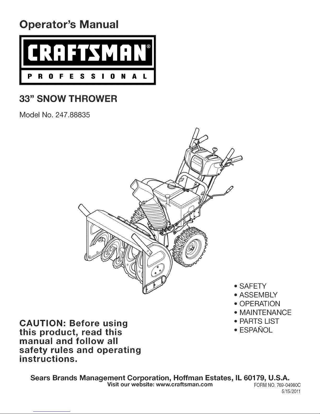
Operator's Manual
P R 0 F E S S I 0 N A L
33" SNOW THROWER
Model No. 247.88835
CAUTION: Before using
this product, read this
manual and follow all
safety rules and operating
instructions.
Sears Brands Management Corporation, Hoffman Estates, IL 60179, U.S.A.
Visit our website: www.craftsman.com FORM1/0.769-04980C
, SAFETY
, ASSEMBLY
, OPERATION
, MAINTENANCE
, PARTS LIST
o ESPANOL
5/15/2011
Page 2
WarrantyStatement..................................Page2
SafeOperation Practices .......................... Page 3
Safety Labels ............................................ Page 7
Assembly .................................................. Page 8
Operation .................................................. Page 13
Service and Maintenance ......................... Page 18
Off-Season Storage .................................. Page 26
Troubleshooting ........................................ Page 27
Parts List ................................................... Page 28
Repair Protection Agreement ................... Page 40
Espa_ol ..................................................... Page 41
Service Numbers ...................................... Back Cover
CRAFTSMAN PROFESSIONAL TWO YEAR FULL WARRANTY
FORTWOYEARSfromthedateofpurchase,this productiswarrantedagainstanydefectsin materialor workmanship.A defectiveproductwill
receivefreerepairor replacementif repairisunavailable.
Thiswarrantyappliesforonlyone yearfromthedateof purchaseifthis productis everusedwhileprovidingcommercialservicesor if rentedto
anotherperson.
Forwarrantycoveragedetailsto obtainfreerepairorreplacement,visitthe web site:www.craftsman.com
Thiswarranty coversONLYdefects in material andworkmanship. Warrantycoverage does NOTinclude:
• Expendableitemsthatcanwearoutfromnormalusewithinthewarrantyperiod,includingbutnotlimitedtoaugers,augerpaddles,drift
cutters,skidshoes,shaveplate,shearpins,sparkplug,air cleaner,belts,andoilfilter.
• Standardmaintenanceservicing,oilchanges,or tune-ups.
• Tire replacementor repaircausedby puncturesfromoutsideobjects,suchas nails,thorns,stumps,or glass.
• Tireorwheelreplacementor repairresultingfromnormalwear,accident,orimproperoperationor maintenance.
• Repairsnecessarybecauseof operatorabuse,includingbutnotlimitedtodamagecausedbyover-speedingtheengine,orfromimpacting
objectsthatbendtheframe,augershaft,etc.
• Repairsnecessarybecauseof operatornegligence,includingbutnotlimitedto,electricalandmechanicaldamagecausedbyimproper
storage,failureto usethe propergradeandamountofengineoil,or failureto maintaintheequipmentaccordingtotheinstructionscontained
intheoperator'smanual.
• Engine(fuelsystem)cleaningorrepairscausedbyfueldeterminedto becontaminatedoroxidized(stale).In general,fuelshouldbeused
within30 daysof itspurchasedate.
• Normaldeteriorationandwearof the exteriorfinishes,orproductlabelreplacement.
Thiswarrantygivesyouspecificlegalrights,andyou mayalso haveotherrightswhichvaryfromstatetostate.
Sears Brands Management Corporation, Hoffman Estates, IL 60179
EngineOilType: 5W-30
EngineOilCapacity: 37ounces
FuelCapacity: Approx.5 Quarts
SparkPlug: F6RTC(951-10292)
SparkPlugGap: .020"to.030"
©SearsBrands,LLC
ModelNumber.................................................................
Serial Number .................................................................
Dateof Purchase.............................................................
Recordthemodelnumber,serialnumber
anddateof purchaseabove
2
Page 3
Thissymbolpointsoutimportantsafetyinstructionswhich,if not
followed,couldendangerthepersonalsafetyand/orpropertyof
yourselfandothers. Readandfollowall instructionsin thismanual
beforeattemptingto operatethismachine.Failuretocomplywith
theseinstructionsmayresultin personalinjury.Whenyou seethis
symbol,HEEDITSWARNING!
Thismachinewasbuiltto beoperatedaccordingtothesafeopera-
tionpracticesinthis manual.Aswithanytypeof powerequipment,
carelessnessorerroron thepartof the operatorcanresultin serious
injury.Thismachineiscapableofamputatingfingers,hands,toes
andfeetandthrowingdebris.Failuretoobservethefollowingsafety
instructionscouldresultin seriousinjuryor death.
CALIFORNIA PROPOSITION 65
EngineExhaust,someof itsconstituents,andcertainvehicle
componentscontainoremitchemicalsknownto Stateof California
tocausecancerandbirthdefectsorotherreproductiveharm,
TRAiNiNG
• Read,understand,andfollowall instructionson the machineand
in themanual(s)beforeattemptingtoassembleandoperate.
Failuretodo socan resultinseriousinjurytothe operatorand/
orbystanders.Keepthismanualina safeplaceforfutureand
regularreferenceandfororderingreplacementparts. Forques-
tionscall,1-800-4MY-HOME.
• Befamiliarwithall controlsandtheirproperoperation.Knowhow
tostopthemachineanddisengagethemquickly.
Neverallowchildrenunder14yearsof agetooperatethis
machine.Children14andovershouldreadandunderstandthe
instructionsandsafeoperationpracticesinthismanualandon
themachineandbe trainedandsupervisedbyanadult.
Neverallowadultsto operatethis machinewithoutproper
instruction.
• Thrownobjectscancauseseriouspersonalinjury.Planyour
snow-throwingpatterntoavoiddischargeof materialtoward
roads,bystandersandthelike.
Keepbystanders,petsandchildrenat least75feetfromthe
machinewhileitisinoperation.Stopmachineifanyoneenters
thearea.
Exercisecautiontoavoidslippingorfalling,especiallywhen
operatinginreverse.
Your Responsibility--Restrict theuseofthispowermachineto
personswhoread,understandandfollowthewarningsand instruc-
tionsin thismanualandon themachine,
SAVE THESE INSTRUCTIONS!
PREPARATION
Thoroughlyinspecttheareawheretheequipmentistobeused.
Removeall doormats,newspapers,sleds,boards,wiresandother
foreignobjects,whichcouldbe trippedoverorthrownbytheauger/
impeller.
Alwayswearsafetyglassesoreyeshieldsduringoperationand
whileperformingan adjustmentor repairto protectyoureyes.
Thrownobjectswhichricochetcancauseseriousinjurytothe
eyes.
Donot operatewithoutwearingadequatewinteroutergarments.
Donot wearjewelry,longscarvesorotherlooseclothing,which
couldbecomeentangledinmovingparts.Wearfootwearwhich
willimprovefootingonslipperysurfaces.
Usea groundedthree-wireextensioncordand receptaclefor all
machineswithelectricstartengines.
Disengageall controlleversbeforestartingtheengine.
Adjustcollectorhousingheighttocleargravelorcrushedrock
surfaces.
Neverattempttomakeanyadjustmentswhileengineis running,
exceptwherespecificallyrecommendedintheoperator'smanual.
Letengineandmachineadjusttooutdoortemperaturebefore
startingtoclearsnow.
3
Page 4
SafeHandlingof Gasoline
Toavoidpersonalinjuryor propertydamageuseextremecarein
handlinggasoline.Gasolineisextremelyflammableandthevaporsare
explosive.Seriouspersonalinjurycan occurwhengasolineisspilled
onyourselforyourclotheswhichcan ignite.Washyourskinand
changeclothesimmediately.
• Useonlyanapprovedgasolinecontainer.
• Extinguishall cigarettes,cigars,pipesandother sources
ofignition.
• Neverfuelmachineindoors.
• Neverremovegascapor addfuelwhiletheengineishot
or running.
• Allowengineto coolat leasttwo minutesbeforerefueling.
• Neveroverfill fueltank.Filltankto no morethan1/2inch
belowbottomoffillerneckto providespaceforfuel
expansion.
• Replacegasolinecapandtightensecurely.
• Ifgasolineisspilled,wipeit offtheengineandequipment.
Movemachinetoanotherarea.Wait5 minutesbefore
startingtheengine.
• Neverstorethemachineor fuel containerinsidewhere
thereis anopenflame,sparkor pilotlight (e.g.furnace,
waterheater,spaceheater,clothesdryeretc.).
• Allowmachinetocoolatleast5 minutesbeforestoring.
• Neverfillcontainersinsidea vehicleorona truckor trailer
bedwitha plasticliner.Alwaysplacecontainersonthe
groundawayfromyourvehiclebeforefilling.
• If possible,removegas-poweredequipmentfromthetruck
ortrailerand refueliton the ground.If thisisnotpossible,
thenrefuelsuchequipmentona trailerwitha portable
container,ratherthanfromagasolinedispensernozzle.
• Keepthenozzleincontactwiththe rimofthefueltankor
containeropeningatalltimesuntilfuelingis complete.Do
notuse a nozzlelock-opendevice.
OPERATION
• Do not puthandsorfeetnear rotatingparts,in the auger/impeller
housingorchuteassembly.Contactwiththerotatingpartscan
amputatehandsandfeet.
• Theauger/impellercontrolleverisa safetydevice.Neverbypass
itsoperation.Doingsomakesthemachineunsafeandmaycause
personalinjury.
• Thecontrolleversmustoperateeasilyinbothdirectionsand
automaticallyreturntothedisengagedpositionwhenreleased.
• Neveroperatewitha missingordamagedchuteassembly.Keep
all safetydevicesin placeandworking.
• Neverrunanengineindoorsorina poorlyventilatedarea.Engine
exhaustcontainscarbonmonoxide,anodorlessanddeadlygas.
• Do notoperatemachinewhileundertheinfluenceofalcoholor
drugs.
• Mufflerandenginebecomehotandcan causea burn.Do not
touch.Keepchildrenaway.
• Exerciseextremecautionwhenoperatingon orcrossinggravel
surfaces.Stayalertforhiddenhazardsortraffic.
• Exercisecautionwhenchangingdirectionandwhileoperatingon
slopes.Do notoperateonsteepslopes.
• Planyoursnow-throwingpatternto avoiddischargetowards
windows,walls,carsetc.Thus,avoidingpossibleproperty
damageorpersonalinjurycausedbya ricochet.
• Neverdirectdischargeatchildren,bystandersand petsorallow
anyoneinfrontofthemachine.
• Donot overloadmachinecapacitybyattemptingtoclearsnowat
toofastof a rate.
• Neveroperatethismachinewithoutgoodvisibilityorlight.Always
be sureofyourfootingand keepa firmholdon thehandles.Walk,
neverrun.
• Disengagepowerto theauger/impellerwhentransportingor not
in use.
• Neveroperatemachineathightransportspeedson slippery
surfaces.Lookdownand behindand usecarewhenbackingup.
• Ifthemachineshouldstartto vibrateabnormally,stoptheengine,
disconnectthesparkplugwireandgroundit againstthe engine.
Inspectthoroughlyfordamage.Repairanydamagebefore
startingandoperating.
• Disengageall controlleversandstopenginebeforeyouleave
theoperatingposition(behindthehandles).Waituntiltheauger/
impellercomestoa completestopbeforeuncloggingthechute
assembly,makingany adjustments,or inspections.
• Neverputyourhandinthedischargeor collectoropenings.Do
notunclogchuteassemblywhileengineisrunning.Shutoff
engineand remainbehindhandlesuntilall movingpartshave
stoppedbeforeunclogging.
• Useonlyattachmentsandaccessoriesapprovedbythemanufac-
turer(e.g.wheelweights,tirechains,cabsetc.).
• Whenstartingengine,pullcord slowlyuntilresistanceisfelt,then
pull rapidly.Rapidretractionofstartercord(kickback)willpull
handandarmtowardenginefasterthanyoucanletgo.Broken
bones,fractures,bruisesorsprainscouldresult.
• Ifsituationsoccurwhichare notcoveredinthis manual,usecare
andgoodjudgment.ContactCustomerSupportforassistance
andthenameofyournearestservicingdealer.
CLEARING A CLOGGED DISCHARGE CHUTE
Handcontactwiththe rotatingimpellerinsidethe dischargechute
is themostcommoncauseofinjuryassociatedwithsnowthrowers.
Neveruseyourhandtocleanout thedischargechute.
Toclear thechute:
1. SHUTTHEENGINEOFF!
2. Wait 10secondstobe surethe impellerbladeshavestopped
rotating.
3. Alwaysusea clean-outtool,notyourhands.
4
Page 5
MAINTENANCE & STORAGE
• Nevertamperwithsafetydevices.Checktheirproperoperation
regularly.Refertothemaintenanceandadjustmentsectionsof
thismanual.
• Beforecleaning,repairing,or inspectingmachinedisengageall
controlleversandstopthe engine.Waituntiltheauger/impeller
cometoa completestop.Disconnectthe sparkplugwireand
groundagainsttheenginetopreventunintendedstarting.
Checkboltsand screwsforpropertightnessatfrequentintervals
tokeepthe machineinsafeworkingcondition.Also,visually
inspectmachineforanydamage.
Donotchangetheenginegovernorsettingorover-speedthe
engine.Thegovernorcontrolsthe maximumsafeoperatingspeed
oftheengine.
Snowthrowershaveplatesandskidshoesaresubjecttowear
anddamage.Foryoursafetyprotection,frequentlycheckall
componentsand replacewithoriginalequipmentmanufacturer's
(OEM)partsonly."Useofpartswhichdo notmeettheoriginal
equipmentspecificationsmayleadto improperperformanceand
compromisesafety!"
Checkcontrolleversperiodicallytoverifytheyengageanddisen-
gageproperlyandadjust,if necessary.Refertotheadjustment
sectioninthisoperator'smanualforinstructions.
Maintainor replacesafetyandinstructionlabels,asnecessary.
• Observeproperdisposallawsand regulationsforgas,oil,etc.to
protecttheenvironment.
Priorto storing,runmachineafew minutestoclear snowfrom
machineand preventfreezeupof auger/impeller.
Neverstorethemachineorfuelcontainerinsidewherethereisan
openflame,sparkorpilot lightsuchas a waterheater,furnace,
clothesdryeretc.
Alwaysrefertotheoperator'smanualforproperinstructionson
off-seasonstorage.
Checkfuelline,tank,cap,andfittingsfrequentlyforcracksor
leaks.Replaceif necessary.
Donotcrankenginewithsparkplugremoved.
AccordingtotheConsumerProductsSafetyCommission(CPSC)
andtheU.S.EnvironmentalProtectionAgency(EPA),thisproduct
hasan AverageUsefulLifeof seven(7)years,or60 hoursof
operation.AttheendoftheAverageUsefulLifehavethemachine
inspectedannuallybyan authorizedservicedealerto ensurethat
allmechanicalandsafetysystemsareworkingproperlyandnot
wornexcessively.Failureto do socanresultinaccidents,injuries
ordeath.
DO NOT MODIFY ENGINE
Toavoidseriousinjuryor death,do notmodifyengineinanyway.
Tamperingwiththegovernorsettingcanleadtoa runawayengineand
causeittooperateat unsafespeeds.Nevertamperwithfactorysetting
ofenginegovernor.
NOTICE REGARDING EMiSSiONS
EngineswhicharecertifiedtocomplywithCaliforniaandfederal
EPAemissionregulationsfor SORE(SmallOffRoadEquipment)are
certifiedto operateon regularunleadedgasoline,and mayinclude
thefollowingemissioncontrolsystems:EngineModification(EM),
OxidizingCatalyst(OC),SecondaryAirInjection(SAI)and ThreeWay
Catalyst(TWO)if so equipped.
SPARK ARRESTOR
Thismachineisequippedwithaninternalcombustionengineand
shouldnotbe usedonor nearanyunimprovedforest-covered,
brush-coveredorgrass-coveredlandunlesstheengine'sexhaust
systemisequippedwitha sparkarrestormeetingapplicablelocalor
statelaws(ifany)
Ifa sparkarrestorisused,itshouldbe maintainedin effectiveworking
orderbytheoperator.Inthe StateofCaliforniatheaboveis required
bylaw (Section4442oftheCaliforniaPublicResourcesCode).Other
statesmayhavesimilarlaws. Federallawsapplyonfederallands.
A sparkarrestorforthemuffleris availablethroughyournearestSears
PartsandRepairServiceCenter.
Page 6
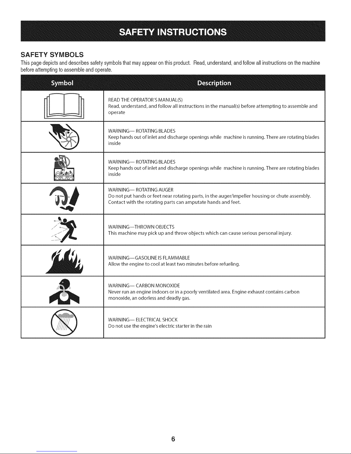
SAFETY SYMBOLS
Thispagedepictsanddescribessafetysymbolsthatmayappearonthisproduct. Read,understand,andfollowall instructionson the machine
beforeattemptingto assembleandoperate.
READ THE OPERATOR'S MANUAL(S)
i
. +
i
Read, understand, and follow all instructions in the manual(s) before attempting to assemble and
operate
WARNING-- ROTATING BLADES
Keep hands out of inlet and discharge openings while machine is running. There are rotating blades
inside
WARNING-- ROTATING BLADES
Keep hands out of inlet and discharge openings while machine is running. There are rotating blades
inside
WARNING-- ROTATING AUGER
Do not put hands or feet near rotating parts, in the auger/impeller housing or chute assembly.
Contact with the rotating parts can amputate hands and feet.
"JIp
WARNING--THROWN OBJECTS
This machine may pick up and throw objects which can cause serious personal injury.
WARNING--GASOLINE IS FLAMMABLE
Allow the engine to cool at least two minutes before refueling.
WARNING-- CARBON MONOXIDE
Never run an engine indoors or in a poorly ventilated area. Engine exhaust contains carbon
monoxide, an odorless and deadly gas+
WARNING-- ELECTRICAL SHOCK
Do not use the engine's electric starter in the rain
6
Page 7
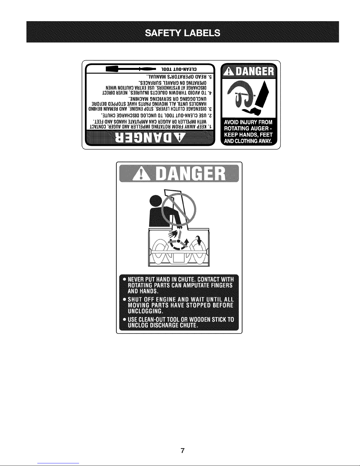
r
100/.LIIO-NV:IIO
"lVflNV_ S,UOIVU3dOQV3H"G
"S3OV_IJflS]3AVUONO9NIIV_J3dO
N3HMNOIIflVOVSIX]qsfl"S9]ONVIS181V]98VHOSIO
10381083A3N'S]IUflrNI SI03PgoNMOUHIQIOAV01 "_
"3NIHOV_ONIOIA83SUOONIOOO]ONfl
]UO_38O3ddOIS]AVHSlHPd9NIAOW11VlllNfl S]IQNVH
ONIH]8NIVW3UONV']NION]dOlS'88]A]1HOlnlo]9VON]SIO"8
"]lnHg ]gHVHOSIO9010Nfl01 1001lflO-NP]lO ]Sfl "Z
"l]]d ONVSONVH]lPlnd_P NVOH3onvuoHq]l]d_JIHIIM
IOVINO0"u39npONV_J3113dWI9NllVIOU_JOH_IVMVd]3H"L
7
Page 8
NOTE:Referencesto rightorleftsideofthe snowthroweraredetermined
fromtheoperatingpositionlookingforwardto thefrontofthemachine.
Handle
REMOVING FROM CRATE
1. Removescrewsfromthe bottomofthecratesecuringthesides,
andendsof theshippingcrate.
2. Liftoffthe top off ofthecrateandsetout of the wayofthe
assemblyarea.
3. Removeanddiscardplasticbagthatcoversunit.
4. Removeanyloosepartsincludedwithunit(e.g.,Operator's
Manual,etc.).
5. Pushdownon the lowerhandleand pullunitbackoutofcrate.
6. Makecertainthecratehas beencompletelyemptiedbefore
discardingit.
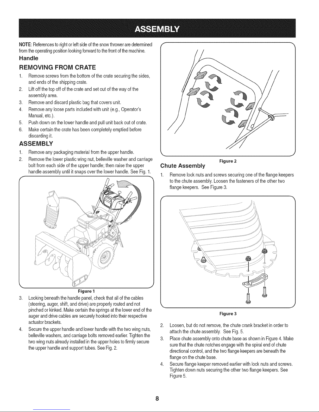
ASSEMBLY
1. Removeanypackagingmaterialfromtheupperhandle.
2. Removethelowerplasticwingnut,bellevillewasherand carriage
boltfromeachsideof the upperhandle;thenraisethe upper
handleassemblyuntilit snapsoverthelowerhandle.SeeFig.1.
_r
Figure 2
,,J
Chute Assembly
1. Removelocknutsandscrewssecuringoneof the flangekeepers
tothechuteassembly.Loosenthefastenersoftheothertwo
flangekeepers. See Figure3.
Figure1
3. Lookingbeneaththehandlepanel,checkthatallofthecables
(steering,auger,shift,anddrive)areproperlyroutedandnot
pinchedorkinked.Makecertainthespringsatthelowerendofthe
augeranddrivecablesaresecurelyhookedintotheirrespective
actuatorbrackets.
4. Securetheupperhandleandlowerhandlewiththetwowingnuts,
bellevillewashers,andcarriageboltsremovedearlier.Tightenthe
twowingnutsalreadyinstalledintheupperholestofirmlysecure
theupperhandleandsupporttubes.SeeFig.2.
\
Figure 3
2. Loosen,butdonotremove,the chutecrankbracketinorderto
attachthe chuteassembly. SeeFig.5.
3. PlacechuteassemblyontochutebaseasshowninFigure4. Make
surethatthechutenotchesengagewiththespiralendof chute
directionalcontrol,andthetwoflangekeepersarebeneaththe
flangeonthe chutebase.
4. Secureflangekeeperremovedearlierwith locknutsand screws.
Tightendownnutssecuringtheothertwo flangekeepers.See
Figure5.
8
Page 9
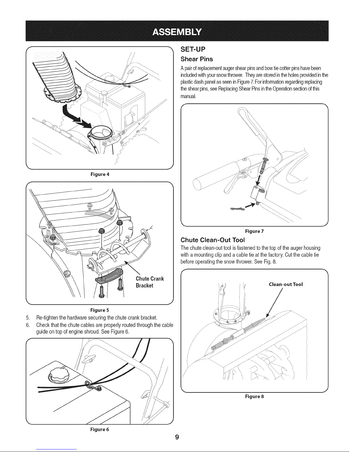
Figure4
SET-UP
Shear Pins
A pairofreplacementaugershearpinsandbowtiecotterpinshavebeen
includedwithyoursnowthrower.Theyarestoredintheholesprovidedinthe
plasticdashpanelas seeninFigure7.Forinformationregardingreplacing
theshearpins,seeReplacingShearPinsintheOperationsectionofthis
manual.
\ \
Figure 5
.
Re-tightenthe hardwaresecuringthechutecrankbracket.
6.
Checkthatthe chutecablesareproperlyroutedthroughthecable
guideontop of engineshroud.SeeFigure6.
Figure7
Chute Clean-Out Tool
Thechuteclean-outtoolisfastenedtothetopoftheaugerhousing
witha mountingclipanda cabletie at the factory.Cutthecabletie
beforeoperatingthe snowthrower.See Fig.8.
/
/
/
/
\
,J
Figure 6
Figure 8
9
Page 10
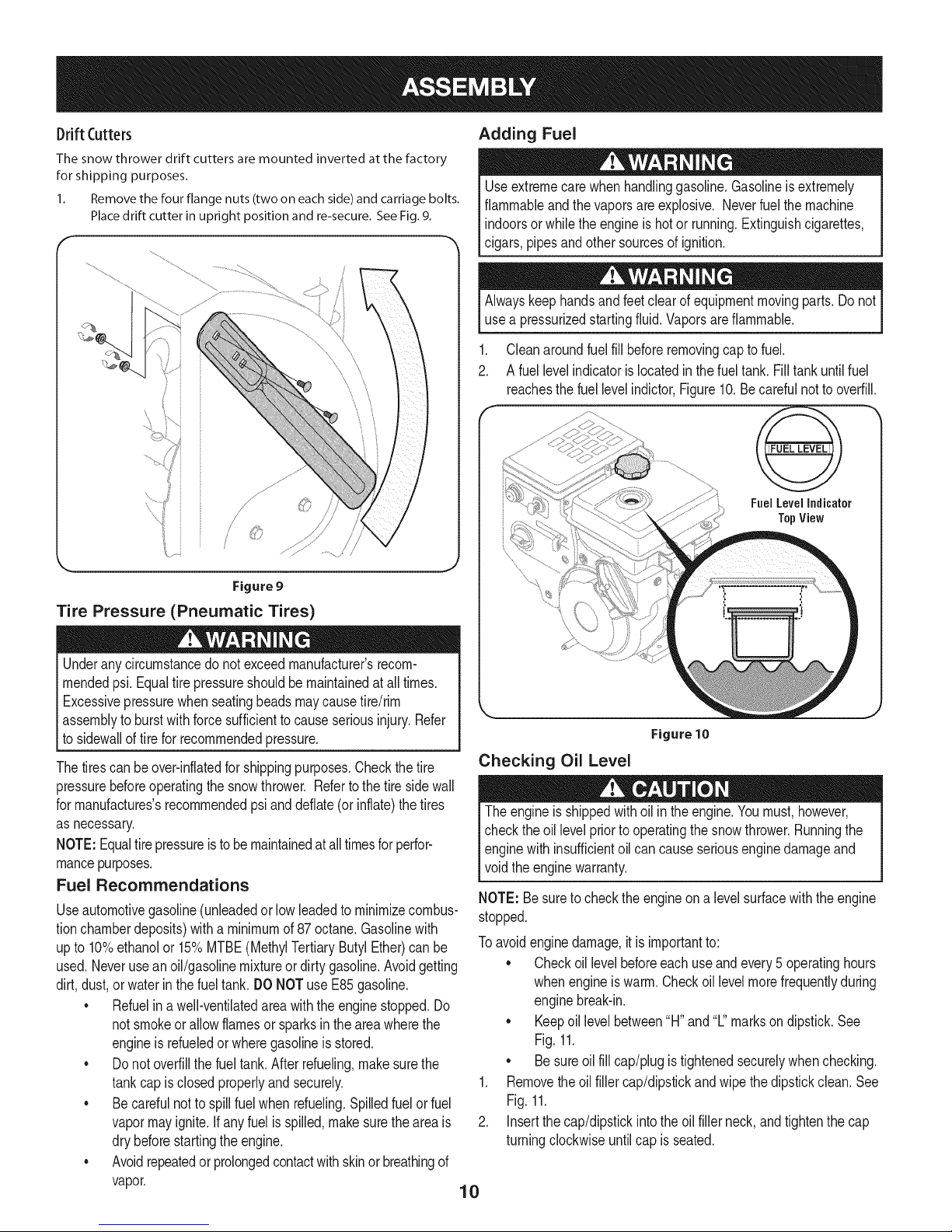
Drift(:utters
The snow thrower drift cutters are mounted inverted at the factory
for shipping purposes.
1. Remove the four flange nuts (two on each side) and carriage bolts.
Place drift cutter in upright position and re-secure. See Fig. 9.
Adding Fuel
Useextremecarewhenhandlinggasoline.Gasolineisextremely
flammableandthe vaporsareexplosive.Neverfuelthemachine
indoorsorwhile theengineis hotor running.Extinguishcigarettes,
cigars,pipesandother sourcesofignition.
Alwayskeephandsandfeetclearofequipmentmovingparts.Donot
usea pressurizedstartingfluid.Vaporsareflammable.
.
Cleanaroundfuel fill beforeremovingcaptofuel.
2.
A fuel levelindicatorislocatedin thefueltank.Fill tankuntilfuel
reachesthefuellevelindictor,Figure10.Becarefulnottooverfill.
Fuel LevelIndicator
TopView
Figure 9
Tire Pressure (Pneumatic Tires)
Underanycircumstancedo notexceedmanufacturer'srecom-
mendedpsi.Equaltirepressureshouldbemaintainedatall times.
Excessivepressurewhenseatingbeadsmaycausetire/rim
assemblytoburstwithforcesufficienttocauseseriousinjury.Refer
tosidewallof tirefor recommendedpressure.
Thetirescanbeover-inflatedfor shippingpurposes.Checkthetire
pressurebeforeoperatingthesnowthrower.Refertothetiresidewall
formanufactures'srecommendedpsianddeflate(orinflate)thetires
asnecessary.
NOTE:Equaltirepressureistobemaintainedatalltimesforperfor-
mancepurposes.
Fuel Recommendations
Useautomotivegasoline(unleadedorlowleadedtominimizecombus-
tionchamberdeposits)witha minimumof87octane.Gasolinewith
upto 10%ethanolor 15%MTBE(MethylTertiaryButylEther)canbe
used.Neveruseanoil/gasolinemixtureordirtygasoline.Avoidgetting
dirt,dust,or waterin thefuel tank. DONOTuseE85gasoline.
* Refuelin awell-ventilatedareawiththeenginestopped.Do
notsmokeorallow flamesor sparksin the areawherethe
engineis refueledor wheregasolineisstored.
* Donotoverfillthefueltank.Afterrefueling,makesurethe
tankcapisclosedproperlyandsecurely.
* Becarefulnot to spillfuelwhenrefueling.Spilledfuelor fuel
vapormayignite.Ifanyfuelisspilled,makesuretheareais
drybeforestartingtheengine.
* Avoidrepeatedorprolongedcontactwithskinor breathingof
vapor.
J
Figure 10
Checking Oil Level
Theengineisshippedwithoil in theengine.Youmust,however,
checkthe oil levelpriorto operatingthesnowthrower.Runningthe
enginewith insufficientoil cancauseseriousenginedamageand
voidtheenginewarranty.
NOTE:Besuretocheckthe engineon a levelsurfacewiththeengine
stopped.
Toavoidenginedamage,itis importantto:
* Checkoil levelbeforeeachuseandevery5 operatinghours
whenengineiswarm.Checkoil levelmorefrequentlyduring
enginebreak-in.
* Keepoillevel between"H"and"L"marksondipstick.See
Fig.11.
* Besureoilfill cap/plugistightenedsecurelywhenchecking.
1. Removetheoilfillercap/dipstickandwipethedipstickclean.See
Fig.11.
2. Insertthecap/dipstickintotheoil fillerneck,andtightenthe cap
turningclockwiseuntilcap is seated.
10
Page 11
f
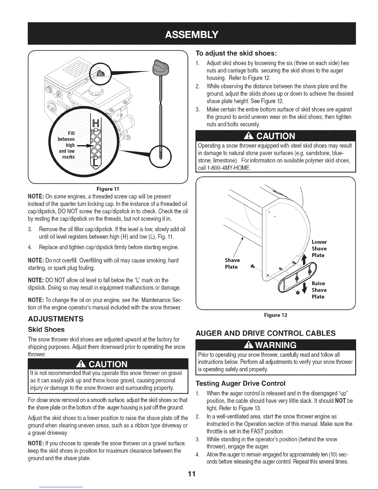
Figure11
NOTE:On someengines,athreadedscrewcapwillbepresent
insteadof thequarterturnlockingcap.In the instanceofathreadedoil
cap/dipstick,DONOTscrewthecap/dipstickin tocheck.Checkthe oil
byrestingthecap/dipstickon thethreads,butnotscrewingitin.
3. Removetheoil fillercap/dipstick.Ifthe levelislow,slowlyaddoil
untiloil levelregistersbetweenhigh(H) andlow(L), Fig.11.
4. Replaceandtightencap/dipstickfirmlybeforestartingengine.
NOTE:Donot overfill.Overfillingwithoil maycausesmoking,hard
starting,or sparkplugfouling.
To adjust the skid shoes:
1. Adjustskidshoesbylooseningthesix (threeoneachside)hex
nutsandcarriagebolts securingtheskidshoestotheauger
housing. Referto Figure12.
2. Whileobservingthedistancebetweentheshaveplateandthe
ground,adjustthe skidsshoesupordowntoachievethedesired
shaveplateheight.SeeFigure12.
3. Makecertaintheentirebottomsurfaceofskidshoesareagainst
thegroundtoavoidunevenwearon theskidshoes;then tighten
nutsandboltssecurely.
Operatinga snowthrowerequippedwith steelskidshoesmayresult
indamageto naturalstonepaversurfaces(e.g.sandstone,blue-
stone,limestone).Forinformationonavailablepolymerskidshoes,
call 1-800-4MY-HOME.
/
Shave
Plate
NOTE:DONOTallowoil leveltofallbelowthe"L"markonthe
dipstick.Doingsomayresultin equipmentmalfunctionsordamage.
NOTE:Tochangetheoilon yourengine,seethe MaintenanceSec-
tionof theengineoperator'smanualincludedwiththe snowthrower.
ADJUSTMENTS
Skid Shoes
Thesnowthrowerskidshoesareadjustedupwardat thefactoryfor
shippingpurposes.Adjustthemdownwardpriortooperatingthesnow
thrower.
It is not recommendedthatyouoperatethissnowthrowerongravel
asitcan easilypick upandthrowloosegravel,causingpersonal
injuryor damagetothesnowthrowerandsurroundingproperty.
Forclosesnowremovalona smoothsurface,adjusttheskidshoessothat
theshaveplateonthebottomofthe augerhousingisjustoff theground.
Adjusttheskidshoestoa lowerpositiontoraisetheshaveplateoff the
groundwhenclearingunevenareas,suchas a ribbontypedrivewayor
a graveldriveway
NOTE:Ifyouchoosetooperatethesnowthrowerona gravelsurface,
keepthe skidshoesin positionfor maximumclearancebetweenthe
groundandtheshaveplate.
Figure 12
AUGER AND DRIVE CONTROL CABLES
Priortooperatingyoursnowthrower,carefullyreadandfollowall
instructionsbelow.Performalladjustmentstoverifyyoursnowthrower
isoperatingsafelyandproperly.
Testing Auger Drive Control
1. Whentheaugercontrolisreleasedandinthe disengaged"up"
position,the cable shouldhaveverylittleslack.It shouldNOTbe
tight.RefertoFigure13.
2. Ina well-ventilatedarea,startthesnowthrowerengineas
instructedintheOperationsectionofthis manual.Makesurethe
throttleis setintheFASTposition.
3. Whilestandingin theoperator'sposition(behindthesnow
thrower),engagetheauger.
4. Allowtheaugertoremainengagedforapproximatelyten(10)sec-
ondsbeforereleasingthe augercontrol.Repeatthisseveraltimes.
11
Page 12
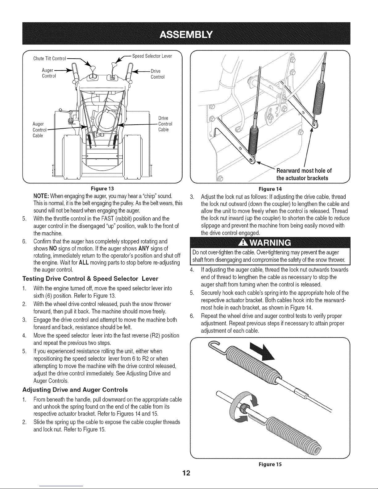
Chut::i: See iil,ever"
Control Control
l I - o ,vo
.liiii o,,!
Figure 13
NOTE:Whenengagingtheauger,youmayheara "chirp"sound.
Thisisnormal,itisthebeltengagingthepulley.Asthebeltwears,this
soundwillnotbeheardwhenengagingtheauger.
5. Withthethrottlecontrolinthe FAST(rabbit)positionandthe
augercontrolin the disengaged"up"position,walktothefrontof
themachine.
6. Confirmthatthe augerhas completelystoppedrotatingand
showsNOsignsof motion,if the augershowsANYsignsof
rotating,immediatelyreturntotheoperator'spositionand shutoff
theengine.WaitforALL movingpartstostopbeforere-adjusting
theaugercontrol.
Testing Drive Control & Speed Selector Lever
1. Withtheengineturnedoff,movethespeedselectorleverinto
sixth(6) position.Referto Figure13.
2. Withthewheeldrivecontrolreleased,pushthe snowthrower
forward,thenpull it back.Themachineshouldmovefreely.
3. Engagethedrivecontroland attemptto movethemachineboth
forwardandback,resistanceshouldbefelt.
4. Movethespeedselector leverinto thefastreverse(R2)position
andrepeattheprevioustwosteps.
5. Ifyou experiencedresistancerollingthe unit,eitherwhen
repositioningthespeedselector leverfrom6 toR2orwhen
attemptingtomovethemachinewiththedrivecontrolreleased,
adjustthedrivecontrolimmediately.SeeAdjustingDriveand
AugerControls.
Adjusting Drive and Auger Controls
1. Frombeneaththehandle,pulldownwardonthe appropriatecable
andunhookthespringfoundonthe endofthecablefromits
respectiveactuatorbracket.RefertoFigures14and 15.
2. Slidethe springupthecable to exposethecablecouplerthreads
andlocknut.Referto Figure15.
Figure14
.
Adjustthe locknutasfollows:if adjustingthedrivecable,thread
thelocknutoutward(downthecoupler)to lengthenthecableand
allowthe unit to movefreelywhenthecontrolis released.Thread
thelocknutinward(upthecoupler)to shortenthe cabletoreduce
slippageandpreventthemachinefrombeingeasilymovedwith
thedrivecontrolengaged.
Donotover-tightenthecable.Over-tighteningmaypreventtheauger
shaftfromdisengagingandcompromisethesafetyofthesnowthrower.
4. Ifadjustingtheaugercable,threadthelock nutoutwardstowards
endofthreadtolengthenthecableasnecessaryto stopthe
augershaftfromturningwhenthecontrolis released.
5. Securelyhookeachcable'sspringintotheappropriateholeofthe
respectiveactuatorbracket.Bothcableshookintothe rearward-
mostholeineachbracket,as shownin Figure14.
6. Repeatthewheeldriveandaugercontrolteststoverifyproper
adjustment.Repeatpreviousstepsifnecessarytoattainproper
adjustmentofeachcable.
Figure 15
12
Page 13
f
Headlight _eedSeJectorLever
FueJTank
FuelCap
OilFill
When DriveControl
ChutePitchControl"
ger Control
WheelSteeringControl
ChuteAssembly
DriftCutter
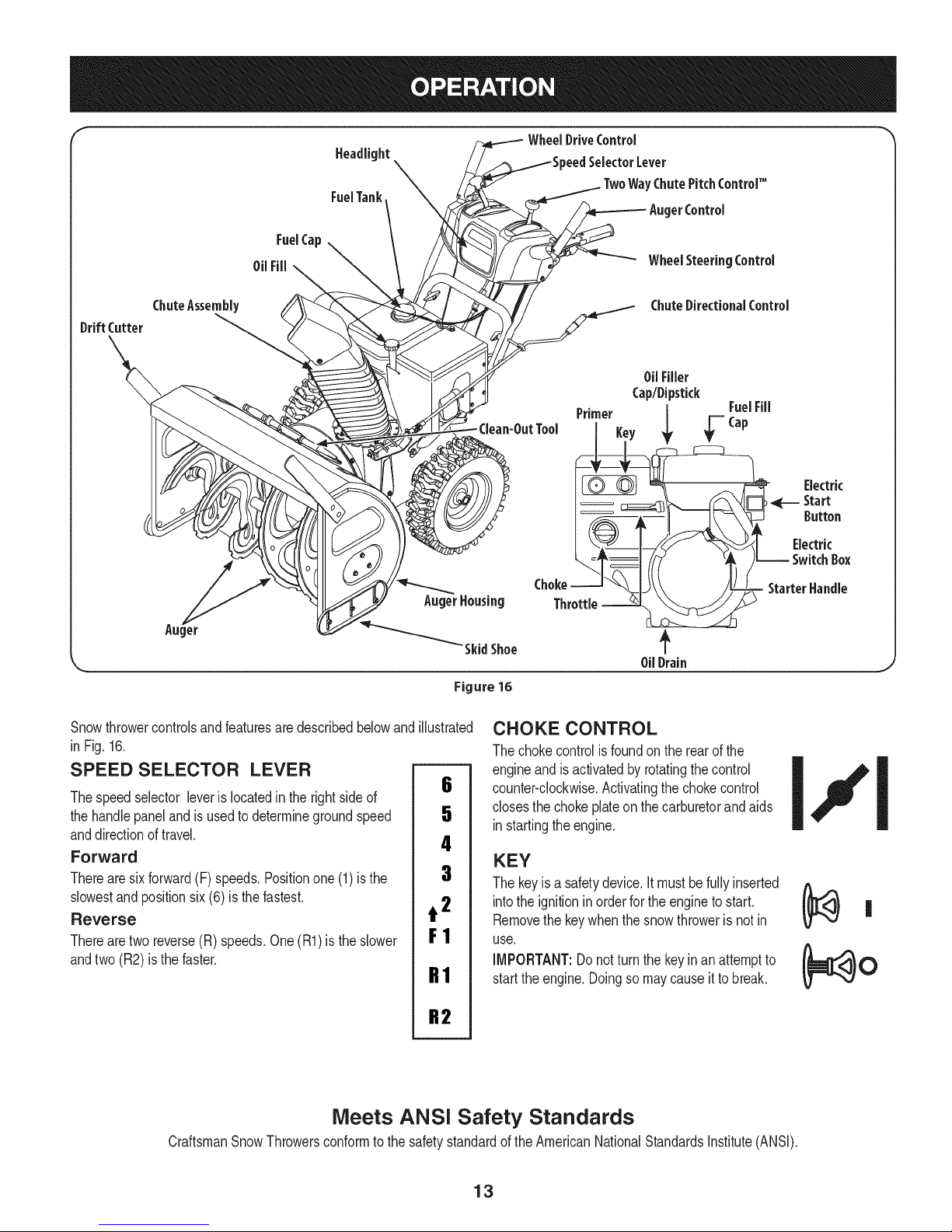
Snowthrowercontrolsandfeaturesaredescribedbelowand
inFig.16.
SPEED SELECTOR LEVER
Thespeedselector leverislocatedin the rightsideof
thehandlepaneland is usedtodeterminegroundspeed
anddirectionoftravel.
Forward
Therearesixforward(F)speeds.Positionone(1)isthe
slowestand positionsix(6) is the fastest.
Reverse
Therearetworeverse(R)speeds.One(R1)is the slower
andtwo(R2) is the faster.
AugerHousing
_Skid Shoe
Figure 16
illustrated
6
5
4
3
t 2
F1
R1
ChuteDirectionalControl
OilFiller
Cap/Dipstick
Primer
Key ; _'=Cap
OilDrain
FuelFill
StarterHandle
CHOKE CONTROL
Thechokecontrolisfoundon therearof the
engineand is activatedbyrotatingthecontrol
counter-clockwise.Activatingthechokecontrol
closesthe chokeplateon thecarburetorandaids
instartingtheengine.
KEY
Thekeyisa safetydevice.Itmust befullyinserted
intothe ignitionin orderfor the engineto start.
Removethe keywhenthe snowthroweris not in
use.
IMPORTANT:Donotturn the keyinan attemptto
startthe engine.Doingso maycauseitto break.
Electric
Start
Button
Electric
Box
CraftsmanSnowThrowersconformtothesafetystandardoftheAmericanNationalStandardsInstitute(ANSI).
R2
Meets ANSi Safety Standards
13
Page 14

THROTTLE CONTROL
Thethrottlecontrolis locatedon therearof theengine.It regulatesthe
speedof the engineandwillshutoff the enginewhenmovedintothe
STOPposition.
PRIMER
Pressingtheprimerforcesfueldirectlyintothe
engine'scarburetortoaid in startinga "Cold" qkfP------=---
engine,orrestartingawarmengine. I
OIL FILL
Engineoillevelcanbecheckedandoil added
throughtheoilfill.
OIL DRAIN
Engineoilcanbedrainedthroughtheoil drain.
FUEL CAP
Un-threadthegascap to addgasolinetothefueltank.
MUFFLER
Engineexhaustexiststheengineviathemuffler.
ELECTRIC STARTER OUTLET
Requirestheuseof a three-prongoutdoorextensioncordanda 120V
powersource/walloutlet.
RECOIL STARTER HANDLE
Thishandleisusedto manuallystartthe engine.
ELECTRIC STARTER BUTTON
Pressingtheelectricstarterbuttonengagestheengine'selectric
starterwhenpluggedintoa 120Vpowersource.
AUGER
Whenengaged,theaugerbladesrotateanddrawsnowintotheauger
housing.
CHUTE ASSEMBLY
Snowdrawnintotheaugerhousingisdischargedoutthechute
assembly.
DRIFT CUTTERS
Thedrift cuttersaredesignedforuse indeepsnow.Theiruseis
optionalfornormalsnowconditions.Maneuverthesnowthrowerso
thatthecutterspenetratea highstandingsnowdrifttoassistsnow
fallingintotheaugersforthrowing.
AUGER CONTROL
AUGER
CONTROL
&
J
Theaugercontrolis locatedon the lefthandle.Squeezethecontrol
gripagainstthehandletoengagetheaugerand startsnowthrowing
action.Releaseto stop.
DRIVE CONTROL / AUGER CLUTCH LOCK
Thedrivecontrolis locatedon therighthandle.Squeezethecontrol
gripagainstthehandletoengagethewheeldrive.Releasethehandle
to stop.
Thedrivecontrolalso lockstheaugercontrolsothatyoucanoperate
thechutedirectionalcontrolwithoutinterruptingthe snowthrowing
process.If theaugercontrolis engagedsimultaneouslywiththedrive
control,theoperatorcanreleasetheaugercontrol(onthelefthandle)
andtheaugerwill remainengaged.Releasebothcontrolsto stopthe
augerand wheeldrive.
NOTE:Alwaysreleasethedrivecontrolbeforechangingspeeds.
Failuretodoso will resultin increasedwearonyourmachine'sdrive
system.
SKiD SHOES
Positiontheskidshoesbasedon surfaceconditions.Adjustupward
forhard-packedsnow.Adjustdownwardwhenoperatingongravelor
crushedrocksurfaces.
14
Page 15
TWO-WAY CHUTE-PITCH CONTROLTM
Thetwo-waychute-pitchcontrolislocatedon theleftsideof the
handlepaneland isusedtocontrolthedistanceofsnowdischarge
fromthechute.
* Tochangetheupperchuteangletocontrolthedistancethat
snowisthrown,pivottheleverforwardor backward.
Movetheleverforwardto pivotthe upperchutedownandreduce
thedistancesnowisthrown.
Movetheleverrearwardtopivottheupperchuteupwardand
increasethe distancesnowisthrown.
NOTE:Toincreaseordecreasethe tensiononthetwo-waychute
control,tightenor loosenthewingknobonthechuteassembly.
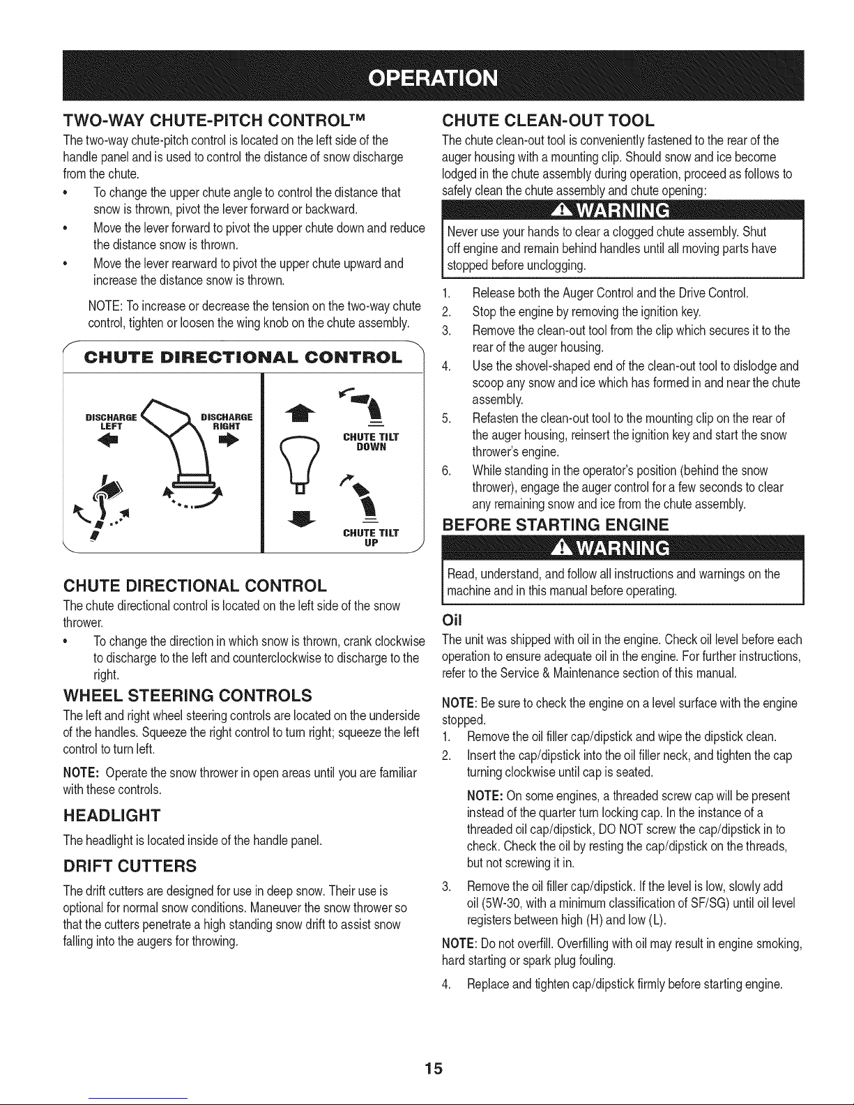
CHUTE DiRECTiONAL CONTROL
DISCHARGE
LEFT
i
i
CHUTE TiLT
DOWN
V
,.b
!
.,j
CHUTE TiLT
UP
CHUTE CLEAN-OUT TOOL
Thechuteclean-outtoolisconvenientlyfastenedtotherearofthe
augerhousingwitha mountingclip.Shouldsnowand icebecome
lodgedinthechuteassemblyduringoperation,proceedasfollowsto
safelycleanthechuteassemblyandchuteopening:
Neveruseyourhandstocleara cloggedchuteassembly.Shut
off engineandremainbehindhandlesuntilall movingpartshave
stoppedbeforeunclogging.
1. ReleaseboththeAugerControlandtheDriveControl.
2. Stoptheenginebyremovingtheignitionkey.
3. Removetheclean-outtoolfromtheclip whichsecuresit tothe
rearoftheaugerhousing.
4. Usetheshovel-shapedendoftheclean-outtooltodislodgeand
scoopanysnowandicewhichhasformedinand nearthechute
assembly.
5. Refastentheclean-outtoolto themountingclipon therearof
theaugerhousing,reinserttheignitionkeyandstartthesnow
thrower'sengine.
6. Whilestandingintheoperator'sposition(behindthesnow
thrower),engagetheaugercontrolfora fewsecondstoclear
anyremainingsnowandicefromthechuteassembly.
BEFORE STARTING ENGINE
.J
CHUTE DIRECTIONAL CONTROL
Thechutedirectionalcontrolislocatedon theleftsideofthe snow
thrower.
* Tochangethedirectioninwhichsnowisthrown,crankclockwise
todischargetotheIdt and counterclockwiseto dischargetothe
right.
WHEEL STEERING CONTROLS
Theleft andrightwheelsteeringcontrolsarelocatedon theunderside
ofthehandles.Squeezethe rightcontroltoturnright;squeezetheleft
controltoturnleft.
NOTE: Operatethesnowthrowerinopenareasuntilyou arefamiliar
withthesecontrols.
HEADLIGHT
Theheadlightislocatedinsideof the handlepanel.
DRIFT CUTTERS
Thedrift cuttersaredesignedforuse indeepsnow.Theiruseis
optionalfornormalsnowconditions.Maneuverthesnowthrowerso
thatthecutterspenetratea highstandingsnowdrifttoassistsnow
fallingintotheaugersforthrowing.
Read,understand,andfollowallinstructionsandwarningsonthe
machineandinthis manualbeforeoperating.
Oil
Theunitwas shippedwith oilin theengine.Checkoillevelbeforeeach
operationtoensureadequateoil intheengine.Forfurtherinstructions,
refertotheService&Maintenancesectionofthis manual.
NOTE:Besureto checktheengineona levelsurfacewiththeengine
stopped.
1. Removetheoilfillercap/dipstickandwipethedipstickclean.
2. Insertthecap/dipstickintotheoilfiller neck,andtightenthe cap
turningclockwiseuntilcap is seated.
NOTE:Onsomeengines,a threadedscrewcapwillbe present
insteadofthequarterturnlockingcap. Intheinstanceofa
threadedoilcap/dipstick,DONOTscrewthecap/dipstickin to
check.Checktheoil byrestingthecap/dipstickon thethreads,
butnot screwingitin.
Removethe oilfillercap/dipstick.Ifthe levelislow,slowlyadd
oil (5W-30,witha minimumclassificationofSF/SG)untiloil level
registersbetweenhigh(H)andlow(L).
NOTE:Donotoverfill.Overfillingwithoil mayresultin enginesmoking,
hardstartingor sparkplugfouling.
4. Replaceandtightencap/dipstickfirmlybeforestartingengine.
15
Page 16
Gasoline
Useextremecarewhenhandlinggasoline.Gasolineisextremely
flammableandthevaporsareexplosive.Neverfuel themachine
indoorsorwhilethe engineis hot or running.Extinguishcigarettes,
cigars,pipesandothersourcesofignition.
Useautomotivegasoline(unleadedorlowleadedtominimizecombus-
tionchamberdeposits)witha minimumof87octane.Gasolinewith
upto 10%ethanolor 15%MTBE(MethylTertiaryButylEther)canbe
used.Neveruseanoil/gasolinemixtureordirtygasoline.Avoidgetting
dirt,dust,or waterin thefuel tank. DO NOTuse E85gasoline.
• Refuelin awell-ventilatedareawiththeenginestopped.Donot
smokeorallowflamesorsparksintheareawheretheengineis
refueledorwheregasolineisstored.
• Do notoverfillthefueltank.Afterrefueling,makesurethetank
capisclosedproperlyandsecurely.
• Becarefulnottospillfuel when refueling.Spilledfuelor fuelvapor
mayignite.Ifany fuel is spilled,makesurethe areaisdrybefore
startingtheengine.
• Avoidrepeatedorprolongedcontactwithskinor breathingofvapor
1. Cleanaroundfuelfill beforeremovingcaptofuelto preventdebris
fromenteringfueltank..
2. Afuel levelindicatorislocatedinthe fuel tank. Filltankuntilfuel
reachesthefuellevelindictor.SeeFigure10inset.Becarefulnot
tooverfill.
STARTING THE ENGINE
Alwayskeephandsandfeetclearofmovingparts.Do notusea
pressurizedstartingfluid.Vaporsareflammable.
Ifyouhaveagroundedthree-prongreceptacle,proceedasfollows.
Ifyoudonot havethe properhousewiring,DONOTusetheelectric
starterunderanyconditions.
1. Plugtheextensioncord intothe outletlocatedon the engine's
surface.Plugtheotherendof extensioncord intoa three-prong
120-volt,grounded,ACoutletina well-ventilatedarea.
2. Movethrottlecontrolto FAST(rabbit)_ position.
3. Movechoketothe CHOKEpositionI.,.,¢1(coldenginestart).
NOTE:Iftheengineis alreadywarm,placechokecontrolin the
RUNpositioninsteadofCHOKEI,,_¢I position.
4. Pushprimerthreetimes(3x),makingsureto coverventholein
primerbulbwhenpushing.Ifengineiswarm,pushprimeronly
once.Alwayscoverventholewhenpushing.Coolweathermay
requireprimingtobe repeated.
5. Pushstarterbuttonto startengine.Oncetheenginestarts,im-
mediatelyreleasestarterbutton.Electricstarterisequippedwith
thermaloverloadprotection;systemwilltemporarilyshut-downto
allowstartertocoolifelectricstarterbecomesoverloaded.
Toprolongstarterlife,useshortstartingcycles(5secondsmaximum
thenwaitone minute).
6. Astheenginewarms,slowlyrotatethechokecontroltotheRUN
position.Iftheenginefalters,restartengineandrunwith choke
at half-chokepositionfor a shortperiodoftime,andthenslowly
rotatethechokeintotheRUNposition.
7. Afterengineis running,disconnectpowercordfromelectric
starter.Whendisconnecting,alwaysunplugtheendat the wall
outletbeforeunpluggingtheoppositeendfromtheengine.
Recoil Starter
NOTE:Allowtheengineto warmupfor a fewminutesafterstarting.
Theenginewill not developfullpoweruntilit reachesoperating
temperatures.
1. Makecertainboththeaugercontrolanddrivecontrolare inthe
disengaged(released)position.
2. Insertkeyintoslot.Makesureit snapsinto place.Do notattempt
toturnthe key.
NOTE:The enginecannotstart withoutthekeyisfullyinsertedintothe
ignitionswitch.
Electric Starter
Theoptionalelectricstarterisequippedwitha groundedthree-wire
powercordandplug,andisdesignedtooperateon 120voltAC
householdcurrent.It mustbeusedwitha properlygroundedthree-
prongreceptacleatalltimesto avoidthepossibilityofelectricshock.
Followall instructionscarefullypriortooperatingtheelectricstarter.
DONOTuseelectricstarterin the rain.
Determinethatyourhome'swiringis a three-wiregroundedsystem.
Aska licensedelectricianifyouarenot certain.
Donot pullthestarterhandlewhiletheenginerunning.
1. Movethrottlecontrolto FAST(rabbit)_1 position.
2. Movechoketothe CHOKEI,,,¢1position_(coldenginestart).If
engineiswarm,placechokeinthe RUNposition.
3. Pushprimerthreetimes,makingsureto coverventholewhen
pushing.If engineis warm,pushprimeronlyonce.Alwayscover
ventholewhenpushing.Coolweathermayrequireprimingto be
repeated.
4. Pullgentlyonthestarterhandleuntilit beginsto resist,thenpull
quicklyandforcefullyto overcomethecompression.Engineshould
start.Donotreleasethe handleandallowittosnapback.Return
ropeSLOWLYto originalposition.If required,repeatthisstep.
5. Astheenginewarms,slowlyrotatethechokecontroltotheRUN
position.Iftheenginefalters,restartengineandrunwith choke
at half-chokepositionfor a shortperiodoftime,andthenslowly
rotatethechokeintotheRUNposition.
Toavoidunsupervisedengineoperation,neverleavethemachine
unattendedwiththeenginerunning.Turntheengineoff afteruseand
removekey.
16
Page 17
STOPPING THE ENGINE
Afteryouhavefinishedsnow-throwing,runenginefora fewminutes
beforestoppingto helpdryoff anymoistureon theengine.
1. Movethrottlecontrolto STOPi_ position.
DoNOTmovethechokecontroltoCHOKE IJl positiontostop
theengine.Backfireorenginedamagemayoccur.
2. Removethekey.Removingthekeywill reducethepossibilityof
unauthorizedstartingoftheenginewhileequipmentis notin use.
Keepthekeyina safeplace.Theenginecannotstartwithoutthe
key.
3. Wipeallsnowandmoisturefromtheareaaroundtheengineas
wellastheareainandaroundthewheeldrivecontrolandauger
control.Also,engageand releasebothcontrolsseveraltimes.
TO ENGAGE DRIVE
1. Withthe throttlecontrolin theFast(rabbit)_ position,move
speedselector leverintooneofthesix forward(F)positionsor
two reverse(R) positions.Selectaspeedappropriateforthe
snowconditionsanda paceyou'recomfortablewith.
NOTE: Whenselectinga DriveSpeed,usetheslowerspeeds
untilyouarecomfortableandfamiliarwiththeoperationofthe
snowthrower.
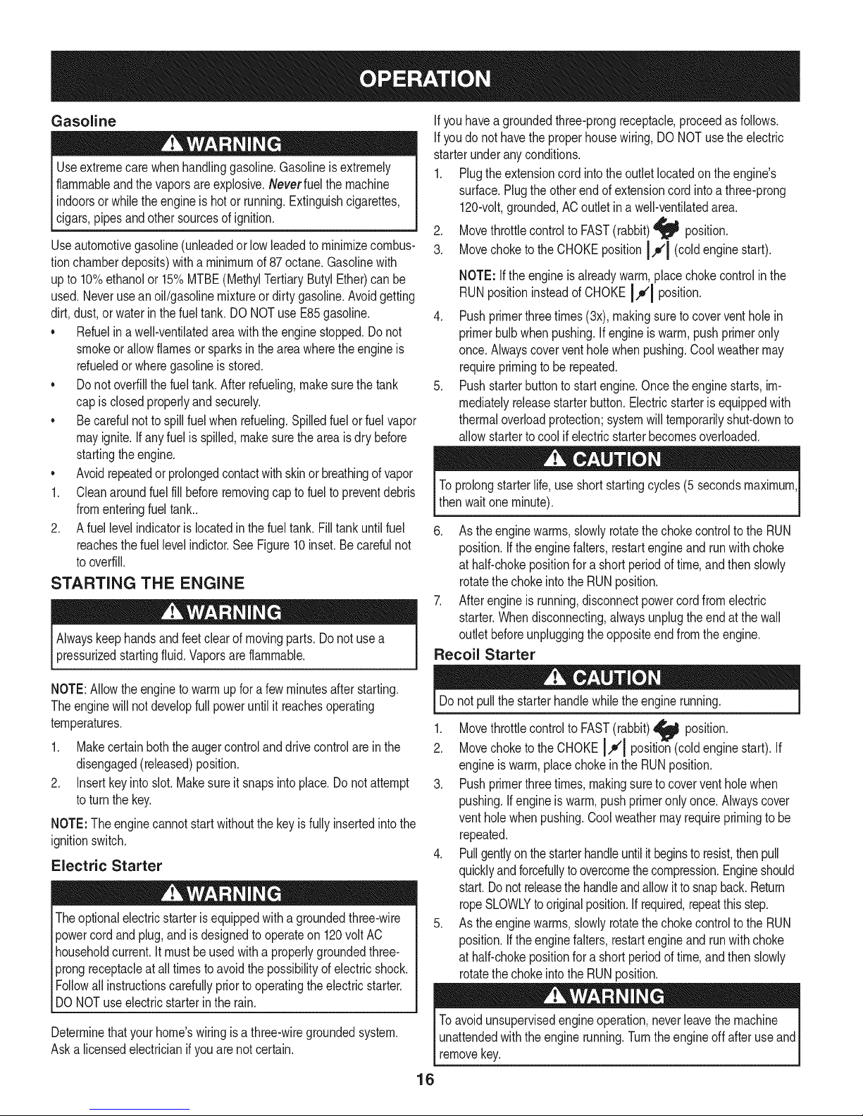
REPLACING SHEAR PiNS
Theaugersaresecuredtothespiralshaftwith shearpinsandbow-tie
cotterpins.Ifthe augershouldstrikeaforeignobjector icejam, the
snowthrowerisdesignedsothatthe pinsmayshear.Iftheaugerswill
notturn,checkto see if the pinshavesheared. SeeFigure17.
NOTE:Twoextrashearpinsaresuppliedin the manualbag.
NEVERreplacetheaugershearpinswithanythingotherthan Sears
SKU#88389/0EM PartNo.738-04155replacementshearpins.Any
damagetotheaugergearboxorothercomponentsasa resultof
failingto do sowill NOTbecoveredbyyour snowthrower'swarranty.
Alwaysturnoffthe snowthrower'sengineandremovethekeypriorto
replacingshearpins.
2. Squeezethedrivecontrolagainstthehandleandthesnow
throwerwillmove.Releaseitand drivemotionwillstop.
NOTE:NEVERrepositionthe speedselectorlever(changespeedsor
directionoftravel)withoutfirst releasingthedrivecontroland bringing
the snowthrowertoa completestop.Doingsowillresultin premature
weartothe snowthrower'sdrivesystem.
TO ENGAGE AUGER
1. Toengagetheaugerandstartthrowingsnow,squeezetheauger
controlagainsttheleft handle.Releasetostoptheauger.
\
Figure17
17
Page 18
MAINTENANCE SCHEDULE
Beforeperforminganytypeofmaintenance/service,disengageall
controlsandstoptheengine.Waituntilallmovingpartshavecometoa
completestop.Removethekeyto preventunintendedstarting.Always
wearsafetyglassesduringoperationorwhileperforminganyadjustments
orrepairs.
EachUse
1st5 - 8 hours
25 hours
50 hours
Annuallyor100hours
1. Engineoillevel
2. Looseormissinghardware
3. Unitandengine.
1. Engineoil
1. Engineoi11-
2. Controllinkagesand pivots
1. Engineoil
1. Sparkplug
1. Check
2. Tightenor replace
3. Clean
1. Change
1. Change
2. Lubewithlightoil
1. Change
1. Cleanand re-gap,orelse replace
withnewplug.
BeforeStorage 1. Fuelsystem
1. Runengineuntilit stopsfromlackof
fueloradda gasolineadditivetothe
gasin thetank.
Underheavyloador inhightemperatures
Followthemaintenanceschedulegivenbelow.Thischartdescribes
serviceguidelinesonly.UsetheServiceLogcolumnto keeptrackof
completedmaintenancetasks.Tolocate the nearestSearsService
Centeror toscheduleservice,simplycontactSearsat
1-800-4-MY-HOME®.
= =
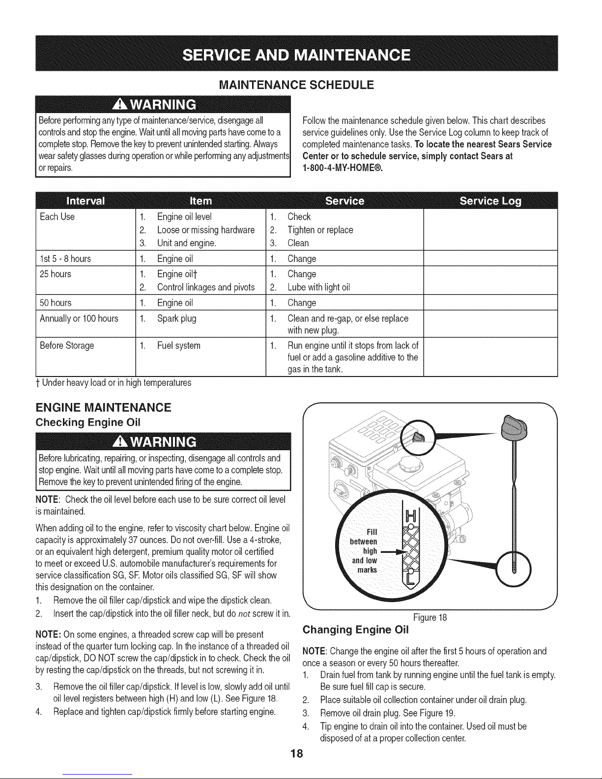
ENGINE MAINTENANCE
Checking Engine Oil
Beforelubricating,repairing,or inspecting,disengageallcontrolsand
stopengine.Waituntilallmovingpartshavecometoa completestop.
Removethekeyto preventunintendedfiringofthe engine.
NOTE: Checktheoil levelbeforeeachuseto besurecorrectoil level
ismaintained.
Whenaddingoiltotheengine,referto viscositychart below.Engineoil
capacityisapproximately37ounces.Donot over-fill.Usea 4-stroke,
oran equivalenthighdetergent,premiumqualitymotoroilcertified
tomeetorexceedU.S.automobilemanufacturer'srequirementsfor
serviceclassificationSG, SR MotoroilsclassifiedSG,SFwillshow
thisdesignationonthe container.
1. Removetheoil fillercap/dipstickandwipethe dipstickclean.
2. Insertthe cap/dipstickintotheoil fillerneck,butdo not screwit in.
NOTE:On someengines,a threadedscrewcap will bepresent
insteadofthequarterturnlockingcap.In the instanceof a threadedoil
cap/dipstick,DONOTscrewthecap/dipstickin tocheck.Checkthe oil
byrestingthecap/dipstickonthethreads,butnot screwingitin.
3. Removetheoil fillercap/dipstick,iflevelislow,slowlyaddoiluntil
oil levelregistersbetweenhigh(H)andlow (L). SeeFigure18.
4. Replaceandtightencap/dipstickfirmlybeforestartingengine.
J
Figure18
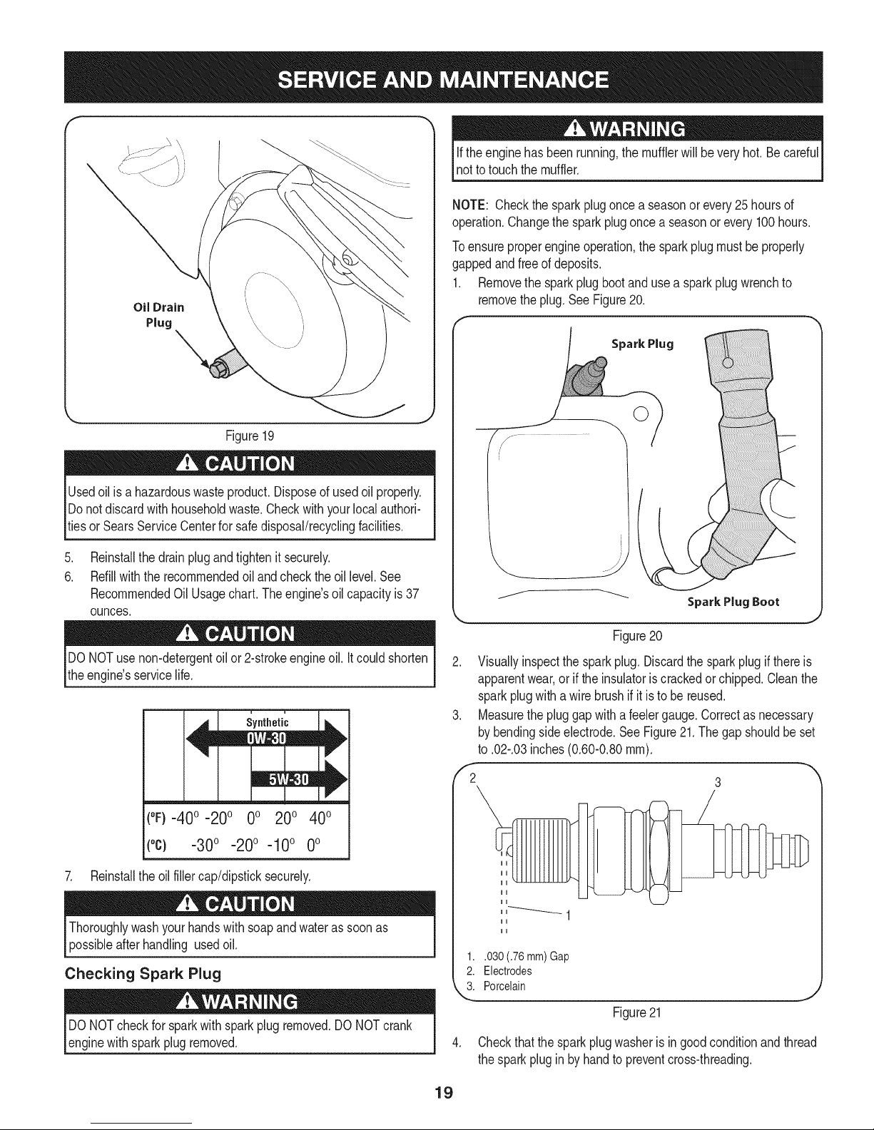
Changing Engine Oil
NOTE:Changetheengineoil afterthefirst 5 hoursof operationand
oncea seasonorevery50 hoursthereafter.
1. Drainfuelfromtankbyrunningengineuntilthefueltankis empty.
Besurefuelfillcapis secure.
2. Placesuitableoil collectioncontainerunderoil drainplug.
3. Removeoil drainplug.SeeFigure19.
4. Tipenginetodrainoil intothe container.Usedoil mustbe
disposedofata propercollectioncenter.
18
Page 19
f
Figure19
Usedoil is a hazardouswasteproduct.Disposeof usedoil properly.
Donotdiscardwith householdwaste.Checkwithyourlocalauthori-
tiesor SearsServiceCenterforsafedisposal/recyclingfacilities.
iftheenginehasbeenrunning,themufflerwillbeveryhot.Becareful
nottotouchthemuffler.
NOTE: Checkthesparkplugonce a seasonor every25 hoursof
operation.Changethe sparkplugoncea seasonorevery100hours.
Toensureproperengineoperation,thesparkplugmustbeproperly
gappedandfreeofdeposits.
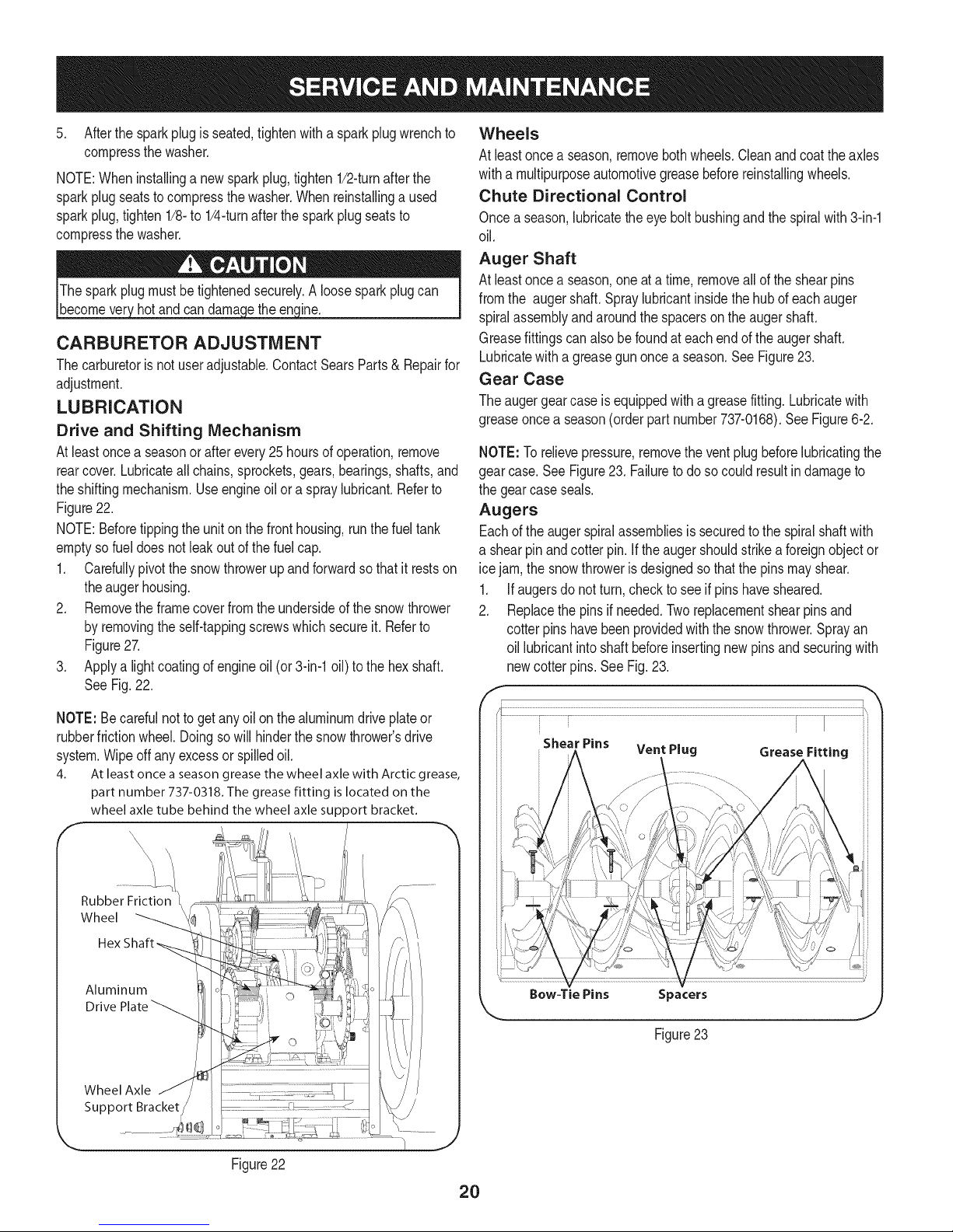
1. Removethesparkplugbootand usea sparkplugwrenchto
removetheplug.SeeFigure20.
Spark Plug
.
Reinstallthedrainplugandtightenit securely.
6.
Refillwiththerecommendedoil andchecktheoil level.See
RecommendedOilUsage chart. The engine's oil capacity is 37
ounces.
DONOTuse non-detergentoilor 2-strokeengineoil.Itcouldshorten
theengine'sservicelife.
(°F}=40o =20o 0o 200 400
(°c) -30° -20° -10° 0°
7. Reinstalltheoilfillercap/dipsticksecurely.
Thoroughlywashyourhandswithsoapandwaterassoonas
possibleafterhandling usedoil.
Checking Spark Plug
DONOTcheckfor sparkwithsparkplugremoved.DONOTcrank
enginewithsparkplugremoved.
Figure20
2. Visuallyinspectthe sparkplug. Discardthe sparkplugif thereis
apparentwear,oriftheinsulatoriscrackedorchipped.Cleanthe
sparkplugwithawirebrushif it is to be reused.
3. Measurethepluggapwitha feelergauge.Correctasnecessary
bybendingsideelectrode.SeeFigure21.Thegap shouldbe set
to .02-.03inches(0.60-0.80ram).
,'2 3
1..030 (.76 mm) Gap
2. Electrodes
k"_i Porcelain
Figure21
4. Checkthatthe sparkplugwasheris ingoodconditionandthread
thesparkpluginbyhandto preventcross-threading.
19
Page 20
5. Afterthe sparkplugis seated,tightenwitha sparkplugwrenchto
compressthewasher.
NOTE:Wheninstallinga newsparkplug,tighten1/2-turnafterthe
sparkplugseatstocompressthewasher.Whenreinstallinga used
sparkplug,tighten1/8-to 1/4-turnafterthesparkplugseatsto
compressthewasher.
hotandcan ine.
CARBURETOR ADJUSTMENT
Thecarburetoris notuseradjustable.ContactSearsParts& Repairfor
adjustment.
LUBRICATION
Drive and Shifting Mechanism
Atleastoncea seasonorafterevery25 hoursofoperation,remove
rearcover.Lubricateallchains,sprockets,gears,bearings,shafts,and
theshiftingmechanism.Useengineoil ora spraylubricant.Referto
Figure22.
NOTE:Beforetippingtheunitonthe fronthousing,runthefueltank
emptyso fueldoesnotleakoutof thefuelcap.
1. Carefullypivotthesnowthrowerupandforwardsothat itrestson
theaugerhousing.
2. Removetheframecoverfromtheundersideofthe snowthrower
byremovingtheself-tappingscrewswhichsecureit. Referto
Figure27.
3. Applya lightcoatingof engineoil (or3-in-1oil) tothehexshaft.
SeeFig.22.
Wheels
At leastoncea season,removebothwheels.Cleanandcoatthe axles
witha multipurposeautomotivegreasebeforereinstallingwheels.
Chute Directional Control
Onceaseason,lubricatetheeyebolt bushingandthespiralwith3-in-1
oil.
Auger Shaft
At leastoncea season,oneat a time,removeallof theshearpins
fromthe augershaft.Spraylubricantinsidethehubofeachauger
spiralassemblyandaroundthespacersonthe augershaft.
Greasefittingscan alsobe foundateachendof the augershaft.
Lubricatewitha greasegunoncea season.SeeFigure23.
Gear Case
Theaugergearcaseis equippedwitha greasefitting.Lubricatewith
greaseoncea season(orderpartnumber737-0168).SeeFigure6-2.
NOTE:Torelievepressure,removethe ventplugbeforelubricatingthe
gearcase.See Figure23. Failuretodosocouldresultindamageto
thegearcaseseals.
Augers
Eachoftheaugerspiralassembliesissecuredtothe spiralshaftwith
a shearpinandcotterpin.If theaugershouldstrikeaforeignobjector
icejam,thesnowthrowerisdesignedsothatthepinsmayshear.
1. Ifaugersdonot turn,checkto seeif pinshavesheared.
2. Replacethepinsif needed.Tworeplacementshearpinsand
cotterpins havebeenprovidedwiththesnowthrower.Sprayan
oil lubricantintoshaftbeforeinsertingnewpinsand securingwith
newcotter pins.See Fig.23.
NOTE:Becarefulnottogetanyoilon thealuminumdriveplateor
rubberfrictionwheel.Doingsowillhinderthesnowthrower'sdrive
system.Wipeoff anyexcessor spilledoil.
4. At least once a season grease the wheel axle with Arctic grease,
part number 737-0318. The grease fitting is located on the
wheel axle tube behind the wheel axle support bracket.
Rubber Friction
Wheel
Aluminum
Drive
Wheel Axle
Support Bracket
Figure22
Shear Pins Vent Plug Grease Fitting
2O
Page 21
SHAVE PLATE AND SKiD SHOES
Theshaveplateand skidshoesonthebottomofthesnowthrowerare
subjectto wear.Theyshouldbecheckedperiodicallyandreplaced
whennecessary.
Skid Shoes
NOTE:Theskidshoesonthismachinehavetwowearedges.When
onesidewearsout, theycan be rotated1800to usethe otheredge.
1. Removethesix carriageboltsandhexnutsthatsecurethetwo
skidshoestothesidesof the augerhousing.Referto Figure24.
2. Positionthenewskidshoesandsecurewiththecarriagebolts
andhexnuts.Makecertaintheskidshoesare adjustedtobe
level.
Shave Plate
1. Removethehexnutsandcarriageboltsthatsecuretheshave
plateto the bottomofthehousing.Referto Figure24.
2. Removetherearmost hexnutand carriageboltsecuringtheback
ofeachskidshoeto the sidesofthehousing.Loosenthefour
remaininghexnutssecuringtheskidshoes.
3. Slidetheshaveplateoutoftheoff-setslotat thebottomofthe
housing,andfrombetweenthe skidshoesandsidepanelsofthe
housing.
4. Withthe mountingholestowardthebackoftheunit,slidethenew
shaveplateinto positionandsecurewiththefastenersremoved
previously.
f
k
J
Figure25
Chute Bracket Adjustment
Ifthespiralatthebottomof thechutedirectionalcontrolis notfully
engagingwiththechuteassembly,thechutebracketcanbeadjusted.
Todo so:
5. Loosenthetwo nutswhichsecurethechutebracketandreposi-
tionit slightly.SeeFigure26.
6. Retightenthenuts.
Figure24
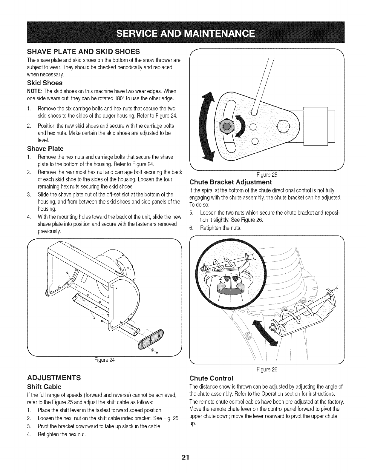
ADJUSTMENTS
Shift Cable
If thefull rangeofspeeds(forwardandreverse)cannotbeachieved,
referto the Figure25 andadjusttheshiftcable as follows:
1. Placetheshiftleverin thefastestforwardspeedposition.
2. Loosenthehex nuton theshiftcable indexbracket.SeeFig.25.
3. Pivotthebracketdownwardto takeupslack inthecable.
4. Retightenthehexnut.
Figure26
Chute Control
Thedistancesnowis throwncanbe adjustedbyadjustingtheangleof
thechuteassembly.Refertothe Operationsectionforinstructions.
Theremotechutecontrolcableshavebeenpre-adjustedatthefactory.
Movethe remotechuteleveronthecontrolpanelforwardtopivotthe
upperchutedown;movetheleverrearwardtopivottheupperchute
up.
21
Page 22
Wheel drive control
RefertotheAdjustmentsectionoftheAssemblyinstructionsto adjust
thewheeldrivecontrol.Tofurtherchecktheadjustment,proceedas
follows:
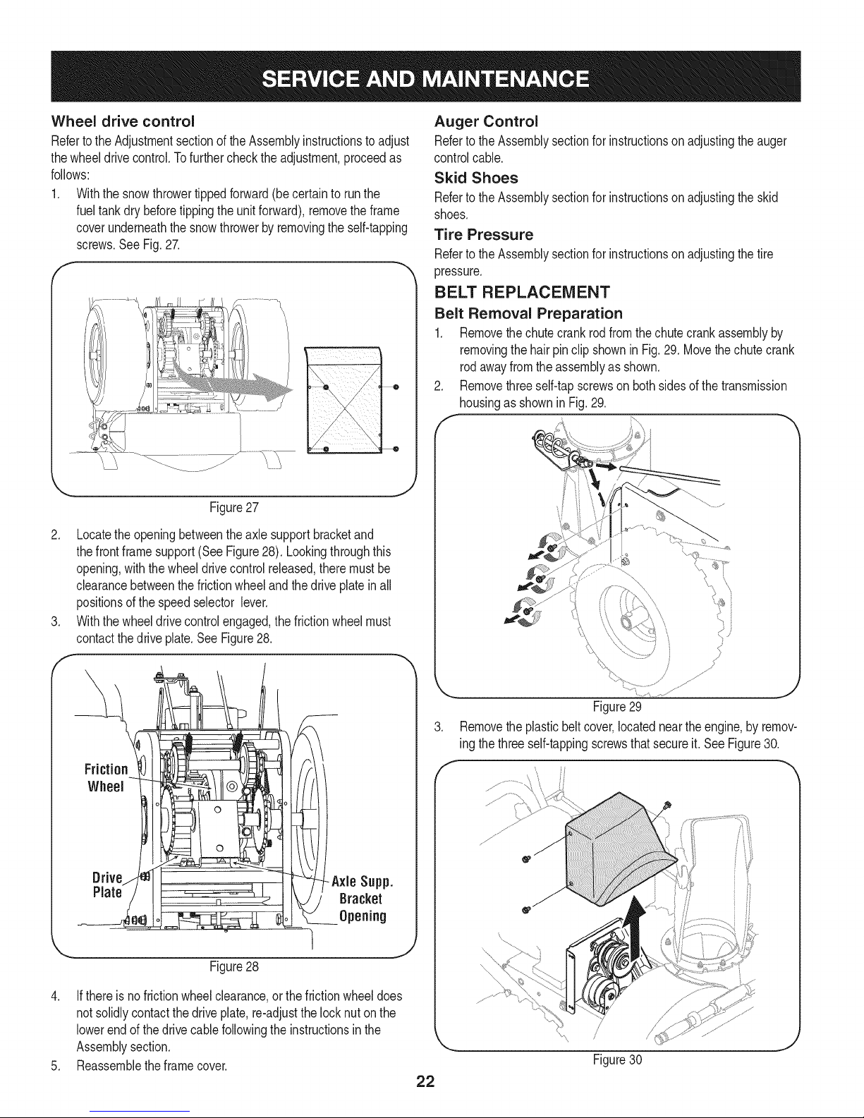
1. Withthe snowthrowertippedforward(becertainto runthe
fueltankdry beforetippingtheunitforward),removetheframe
coverunderneaththe snowthrowerby removingtheself-tapping
screws.SeeFig.27.
J
Figure27
Auger Control
RefertotheAssemblysectionforinstructionson adjustingtheauger
controlcable.
Skid Shoes
RefertotheAssemblysectionforinstructionson adjustingtheskid
shoes.
Tire Pressure
RefertotheAssemblysectionforinstructionson adjustingthetire
pressure.
BELT REPLACEMENT
Belt Removal Preparation
1. Removethechutecrankrodfromthechutecrankassemblyby
removingthehairpinclip shownin Fig.29.Movethechutecrank
rodawayfromtheassemblyas shown.
Removethreeself-tapscrewson bothsidesofthetransmission
housingas shownin Fig.29.
2. Locatetheopeningbetweentheaxlesupportbracketand
thefrontframesupport(SeeFigure28). Lookingthroughthis
opening,withthe wheeldrivecontrolreleased,theremustbe
clearancebetweenthefrictionwheelandthedriveplatein all
positionsofthespeedselectorlever.
3. Withthewheeldrivecontrolengaged,thefrictionwheelmust
contactthedrive plate.SeeFigure28.
Drive -Axle Supp.
Plate Bracket
Opening
Figure29
3. Removetheplasticbeltcover,locatednearthe engine,by remov-
ing thethreeself-tappingscrewsthatsecureit.See Figure30.
f
Figure28
4. Ifthere isnofrictionwheelclearance,orthefrictionwheeldoes
notsolidlycontactthedriveplate,re-adjustthelocknuton the
lowerendofthedrive cablefollowingtheinstructionsinthe
Assemblysection.
5. Reassembletheframecover.
22
Page 23
.
Loosentheboltshownin Figure31securingthe beltkeeper
bracketandremovetheotherbolt.Pushthebeltkeeperand
bracketupoff theenginepulley.
Loosen
\
\
Figure31
Auger Belt Replacement
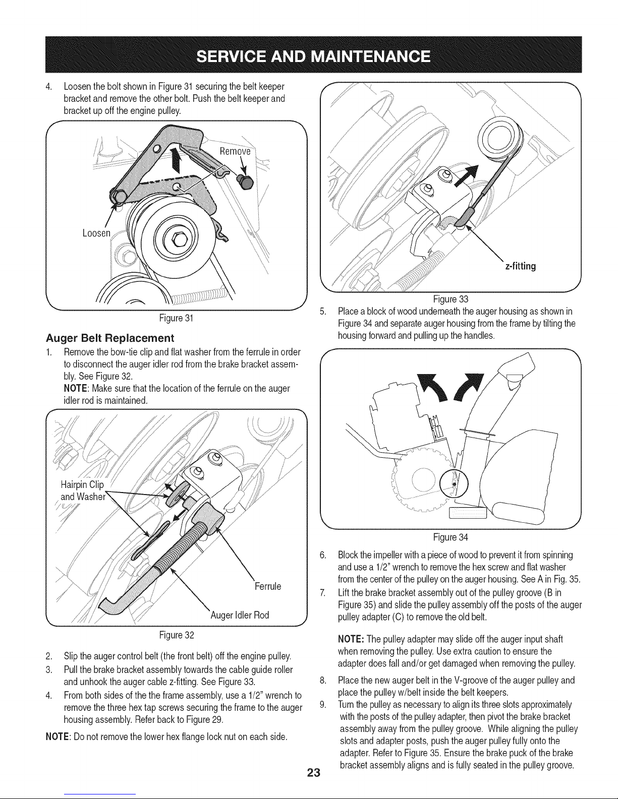
1. Removethebow-tieclipandflatwasherfromtheferrulein order
todisconnecttheaugeridlerrodfromthebrakebracketassem-
bly.SeeFigure32.
NOTE:Makesurethatthe locationof the ferruleon the auger
idlerrodis maintained.
HairpinClip
Ferrule
AugerIdlerRod
z-fitting
J
Figure33
Placeablockof woodunderneaththeaugerhousingasshownin
Figure34 andseparateaugerhousingfromtheframebytiltingthe
housingforwardandpullingupthe handles.
Figure34
6. Blocktheimpellerwithapieceof woodtopreventitfromspinning
andusea 1/2"wrenchtoremovethehexscrewandflatwasher
fromthecenterofthepulleyontheaugerhousing.SeeAinFig.35.
7. Liftthe brakebracketassemblyoutofthepulleygroove(B in
Figure35)andslidethepulleyassemblyoff thepostsof the auger
pulleyadapter(C)to removetheoldbelt.
Figure32
2. Slipthe augercontrolbelt (thefrontbelt) offtheenginepulley.
3. Pullthe brakebracketassemblytowardsthecableguideroller
andunhooktheaugercable z-fitting.SeeFigure33.
4. Frombothsidesofthetheframeassembly,use a 1/2"wrenchto
removethethreehex tap screwssecuringtheframetotheauger
housingassembly.Referbackto Figure29.
NOTE:Do not removethelowerhexflangelocknuton eachside.
23
NOTE:Thepulleyadaptermayslideoff theaugerinputshaft
whenremovingthepulley.Useextracautiontoensurethe
adapterdoesfalland/orgetdamagedwhen removingthepulley.
.
Placethenewaugerbeltin theV-grooveoftheaugerpulleyand
placethepulleyw/beltinsidethebeltkeepers.
9.
Turnthepulleyasnecessaryto alignitsthreeslotsapproximately
withthepostsof thepulleyadapter,thenpivotthe brakebracket
assemblyawayfromthepulleygroove.Whilealigningthepulley
slotsandadapterposts,pushtheaugerpulleyfullyontothe
adapter.RefertoFigure35. Ensurethebrakepuckof the brake
bracketassemblyalignsandis fullyseatedin the pulleygroove.
Page 24

Brake
!
pterPost
%
J
Figure35
NOTE: If the pulleyadapterwasremovedwiththepulley,alignthe
splinesofthepulleyadapterandaugerinputshaft,andpushthe pulley
andadapterontotheinputshaft.Referto Figure35.
10. Slidethewasherontothehexscrewremovedearlierandapply
Loctite262to thethreadsofthehexscrew.
11. Insertthehexscrewthroughthepulleyassemblyandintothe
threadsoftheinputshaft.Torquethehexscrewto250-325in.
Ibs.to securethe augerpulleyassemblyon theinputshaft.
12. Ifalso replacingthedrivebelt,proceedtothe"DriveBelt"instruc-
tions.If not,repositionthetransmissionframebackonto
theaugerhousing.
13. Installthedrive belton theenginepulley,re-connecttheauger
cablez-fittingandaugeridler rodferruletothebrakebracket.
Repositionand securetheenginepulleybeltguard,and re-install
thebeltcover.
NOTE:Makesureto removethepieceofwoodblockingthe impeller.
Checktheaugerdrivebeltadjustment.Withtheaugerclutchlever
inthedisengagedposition,thetopsurfaceof the newbeltshouldbe
evenwiththeoutsidediameterof the pulley.
Toadjust,disconnectferrulefrombrakebracketassembly.Thread
ferrulein(towardsidler)to increasetensiononbelt,orout to decrease
belttension.
J
Figure36
2. Rollthedrivebeltoff thelowerdrivepulley.
3. Removethebeltfromtheenginepulley.
4. Installthe newbelton the pulleysinthe reverseorderand
re-tensionwiththeidlerpulley.
5. Reassemblebyperformingthepreviousstepsintheopposite
orderand mannerofremoval.
CHANGING FRICTION WHEEL
Therubberonthefrictionwheelis subjecttowearandshouldbe
checkedperiodically.Replacethefrictionwheelifanysignsofwearor
crackingarefound.
1. Runthe unit'sfueltankdry beforeperformingStep2. Donot
attempttopourfuelfromtheengine.
2. Tipthesnowthrowerupand forward,sothat it restsonthe
housing.
3. Removescrewsfromtheframecoverunderneaththesnow
thrower(referto Figure37).Removetherightwheelfromthe axle.
NOTE:Thebrakepuckmustalwaysbefirmlyseatedinthepulley
groovewhenaugercontrolisdisengaged.
IMPORTANT:Repeatthe"AugerDriveControlTest"fromtheAs-
semblysectionbeforeoperatingsnowthrower.
Drive Belt Replacement
If notalreadydone,removetheaugerdrivebeltfromthefrontpulleyof
theenginedoublepulley.Referto"AugerBeltReplacement"instruc-
tionsintheprevioussub-section.
1. a.Pullthe idlerpulleyawayfromthebacksideofthe drivebeltto
relievethetension.SeeFigure36.
b.Slipthedrivebeltoffthe idlerpulley.Carefullyreleasetheidler
pulley.
e
Figure37
24
Page 25

.
Usinga 3/4"wrench,holdthehexshaftandremovethehex
screwandbellevillewasherand bearingfromleft sideofthe
frame.Referto Figure38.
f
RemoveHexScrew
BellevilleWasher
l,
Figure38
.
Holdingthefrictionwheelassembly,slidethe hex shaftoutof
thefrictionwheelassemblyandthe rightsideof theframe.The
spacerontheleft sideofthehexshaftwillfall andthesprocket
shouldremainhanginglosein thechain.
.
Liftthefrictionwheelassemblyoutbetweentheaxleshaftand
thedriveshaftassemblies.
7.
Removefourscrewssecuringthefrictionwheeltothehub
assembly(referto Figure39).Discardoldfrictionwheel.
FrictionWheelAss'y.
/
SlideHex
ShaftOut
RightSide
f
!!Si¸i¸i¸;i!!¸i¸:¸¸i¸¸i¸!_¸¸_!¸¸i¸¸¸¸¸¸¸¸¸¸¸¸¸'¸¸¸"i!i_i_!!!i!i;i!iiiiii!iiiii
f
_,,, J
8. Reassemblethenewfrictionwheelontothehubassembly,
tighteningthefourscrewsin rotationandwithequalforce.It is
importanttoassemblethefrictionwheelsymmetricallyforproper
functioning.
9. Repositionthefrictionwheelassemblyin the snowthrowerframe.
Insertthe pinfromthespeedselectorarmassemblyintothe
frictionwheelassemblyandholdassemblyin position.Referto
Figure40.
_L
¢,
Figure39
0
Figure40
10. Slidethehexshaftthroughtherightsideoftheframetowardthe
Idt sideandthroughthefrictionwheelassembly.
11. Aftermakingcertainthatthechainis on boththe largeandthe
smallsprocket,alignthehexshaftwiththehexhubof the small
sprocket,andslidethe shaftthroughthesprocket.
NOTE:Ifthesprocketfellfromthesnowthrowerwhileremoving
thehexshaft,placethe sprocketonthechain.Realignthe
sprocketonthechainwiththehexhubfacingtherightsideof
unit.Positionthehexhubofthesprockettowardthefrictionwheel
whenslidingthesprocketon tothe hexshaft.
12. Slidethespacerontotheendofthehexshaft.
Note:Thespaceristobe placedon thehexshaftbetweenthe
sprocketandbearingpreviouslyremovedonthe leftsideofthe
frame.
13. Alignthe bearingontherightendof thehex shaftwiththe hole
intherightsideoftheframe,thenpushthehexshaftto the left
intopositionintheframe.
14. Slidethebearingontotheleftendofthehexshaftandpressinto
theholeon theleft sidetheframe.
15. Placethebellevillewasher(roundedsidetowardhead)ontothe
hexscrewremovedearlier,andinsertthescrewintothethreaded
holeofthehexshaft.
16. Graduallytightenthehexscrewtofullyseatthebearingsineach
sideof the frameandtosecurethehexshaft.
17. Positiontheframecoveron thebottomoftheframeand secure
withtheself-tappingscrews.Pivotthesnowthrowerdownto it
normaloperatingposition.
iMPORTANT:Repeatthedrivecontroltestfromthe Assemblysection
ofthis manualbeforeoperatingthesnowthrower.
25
Page 26

Ifthesnowthrowerwillnotbeusedfor30daysorlonger,orifitistheendofthesnowseasonwhenthelastpossibilityofsnowisgone,the
equipmentneedstobestoredproperly.Followstorageinstructionsbelowtoensuretopperformancefromthesnowthrowerformanymoreyears.
PREPARING ENGINE
Enginesstoredover30daysneedtobedrainedoffueltoprevent
deteriorationandgumfromforminginfuelsystemoronessential
carburetorparts.If thegasolineinyourenginedeterioratesduring
storage,youmayneedto havethecarburetor,andotherfuelsystem
components,servicedor replaced.
1. Removeallfuelfromtank byrunningengineuntilitstops.Donot
attempttopourfuelfromtheengine.
2. Changetheengineoil.
3. Removesparkplugandpourapproximately1oz.(30 rnl)ofclean
engineoil intothecylinder.Pullthe recoilstarterseveraltimesto
distributetheoil,and reinstallthesparkplug.
4. Cleandebrisfromaroundengine,andunder,around,andbehind
muffler.Applya lightfilmofoilon anyareasthatare susceptible
torust.
• Storeinaclean,dry andwellventilatedareaawayfromanyap-
pliancethatoperateswithaflameor pilotlight,suchasa furnace,
waterheater,or clothesdryer.Avoidany areawitha spark
producingelectricmotor,orwherepowertoolsareoperated.
Neverstoresnowthrowerwithfuel intank indoorsor inpoorlyventi-
latedareas,wherefuelfumesmayreachanopenflame,sparkor pilol
lightas ona furnace,waterheater,clothesdryerorgasappliance.
PREPARING SNOW THROWER
Whenstoringthe snowthrowerin anunventilatedormetalstor-
age shed,careshouldbetakentorustprooftheequipment.Using
a light oilor silicone,coattheequipment,especiallyanychains,
springs,bearingsandcables.
• Removealldirt fromexteriorofengineandequipment.
• Followlubricationrecommendations.
• Storeequipmentinaclean,dryarea.
• If possible,avoidstorageareaswithhighhumidity.
• Keepthe enginelevelin storage.Tiltingcancausefueloroil
leakage.
26
Page 27

Enginefailstostart
Enginerunningerratically/
inconsistentRPM(huntingor
surging)
Excessivevibration
Lossofpower
Unitfailstopropelitself
Unitfailstodischargesnow
1. ChokecontrolnotinCHOKEposition.
2. Sparkplugwire disconnected.
3. Faultysparkplug.
4. Fueltankemptyor stalefuel.
5. Enginenotprimed.
6. Keynot inserted.
7. Extensioncordnotconnected(when
usingelectricstartbutton,on modelsso
equipped).
1. EnginerunningonCHOKE.
2. Stalefuel.
3. Waterordirt infuelsystem.
4. Over-governedengine.
1. Loosepartsor damagedauger.
1. Sparkplugwire loose.
2. Gascap ventholeplugged.
1. Drivecableinneedofadjustment.
2. Drivebeltlooseor damaged.
3. Wornfrictionwheel.
1. Chuteassemblyclogged.
2. Foreignobjectlodgedin auger.
3. Augercablein needof adjustment.
4. Augerbeltlooseordamaged.
5. Shearpin(s)sheared.
1. Movechokecontrolto CHOKEposition.
2. Connectwireto sparkplug.
3. Clean,adjustgap,or replace.
4. Filltankwith clean,freshgasoline.
5. PrimeengineasinstructedintheOperationSection.
6. Insertkeyfully intothe switch.
7. Connectoneendoftheextensioncordtotheelectric
starteroutletandtheotherendtoa three-prong
120-volt,grounded,ACoutlet.
1. Movechokecontrolto RUNposition.
2. Filltankwith clean,freshgasoline.
3. Drainfueltank. Refillwithfreshfuel.
4. ContactyourSearsParts& RepairCenter.
1. Stopengineimmediatelyand disconnectsparkplug
wire.Tightenall boltsand nuts.Ifvibrationcontinues,
haveunit servicedbya SearsParts& RepairCenter.
1. Connectandtightensparkplugwire.
2. Removeiceand snowfromgascap. Becertainvent
holeisclear.
1. Adjustdrivecontrolcable.RefertoServiceand
Maintenancesection.
2. Replacedrivebelt.Referto Serviceand Mainte-
nancesection.
3. ChangefrictionwheelorcontactyourSearsParts&
RepairCenter.
1. Stopengineimmediatelyand disconnectsparkplug
wire.Cleanchuteassemblyandinsideofauger
housingwithclean-outtoolor astick.
2. Stopengineimmediatelyand disconnectsparkplug
wire.Removeobjectfromaugerwith clean-outtool
ora stick.
3. Adjustaugercontrolcable.Referto Assembly
section.
4. Replaceaugerbelt.RefertoServiceand Mainte-
nancesection.
5. Replacewith newshearpin(s).
Chutefailstoeasilyrotate180 1. Unassemblechutecontrolandreassembleas
1. Chuteassembledincorrectly.
degrees directedintheAssemblysection.
NEED MORE HELP?
YouT! fi_d the answer: and :moR÷on _a_agemylifeocem _ fo_ free!
o Hnd this and aLLyour other product manuals online.
oGet answers from our team of home experts.
Get a personalized maintenance plan for your home.
Find information and tools to help with home projects.
Page 28

Craftsman Snow Thrower Model 247.88835
19
48
/-
10
4
42
/
49 11
43 41
• 28
35
Page 29

Craftsman Snow Thrower Model 247.88835
D = = 0 0
918-0281A Bracket Assy, Auger Brake
2. 684-0090B-0637 Impellar, 16"
3. 931-2643 Tool, Cleanout
4. 710-0376 Scr,Hex Cap, 5/16-18 x 1.00
5. L 710-04484 I Screw, 5/16-18 x .750
6. 710-0451 Screw, Carriage, 5/16-I 8 x .75
7. 710-04606A Screw, 5/16-18 x .4300
8. 710-1245B Screw, 5/16-24 x .875
9. 911-0677 Ferrule
10. 712-04063 Nut, Flnge Lk, 5/16-18
11. 712-04065 Nut, Fig Lk, 3/8-16
12. 914-0135 Key, Woodruff, I/4 x 3/4
13. 714-04040 Pin, Bowtie Cotter
14. 915-0118 Pin, Spirol, 5/16 x 1.75
15. 725-0157 Tie, Cable
16. 926-04012 Nut, Push
17. 731-1696B Adapter, Chute, 6"
18. 732-0858 Spring, Extension
19. 936-0159 Washer, .349 x .879 x .063
20. 736-0174 Washer, .625 x .885 x .015
21. 736-0505 Washer, Flat, .34 x 1.50 x .150
22. 936-3008 Washer, .344 x .75 x .12
23. 736-3046A Washer, 1.01 x 1.86 x .06
24. 731-2635 Clip, Mounting
25. 938-0281 Screw, Shoulder, .625 x .17
26. 738-04155 Pin, Shear, .25 x 1.75
27. 741-0192 Bearing, Flange w/Flats
28. 941-04024 Bearing, Self Aligning
29. 747-0980A Rod, Auger Idler
30. 748-04067A Pulley, Adapter, .75 Dia.
31. 950-04020 Spacer, 1.004 x 1.375 x .25
32. 756-04244A Pulley, Auger Drive, 10.0
33. 790-00264A-0637 Bracket, Gear Box Support
34. 05244B Housing, Bearing
35. 784-0315A-0637 Housing, Bearing
D = = I! II
918-04514 Gear Box Assembly, Auger
37. 684-04151-4028 Spiral Assy, LH
38. 684-04152-4028 Spiral Assy, RH
39. 684-04214-0691 Housing, Auger - 33"
40. 731-05162 Spacer, 1.0 x 1.5 x 2
41. 731-05163 Spacer, 1.0 x 1.5 x 1
42. 938-04158 Axle, Spiral, 33"
43. 741-0494 Bushing, Flange, 1.051 x 1.16
44. 784-5714B-0637 Shave Plate
45. 710-0389 Bolt, Carriage, 3/8-16 x .750
46. 710-3168 Bolt, Carriage, 3/8-16 x 1.0
47. 784-5697-0637 Shoe, Skid
48. 790-00181-0637 Drift Cutter
49. 929-0071A Extension Cord, 110V
50. 918-0246 Hsg Assy Auger RH (Inc. 65 & 66)
51. 918-0247 Hsg Assy Auger LH (Inc. 65 & 66)
52. 710-1260A Screw, LD, 5/16-18 x .750
53. . 711-04714 _ Shf, Drive, Auger
54. 914-0126 Key, Hi Pro, 3/16 x 3/4
55. 716-0111 Ext, Ret, Ring
56. 917-0299 Gear, Worm, Dbl Thread
5Z 917-1425 Gear, Worm, LH
58. 921-0145 Seal, Oil
59. 721-0325 Plug
60. 936-0266 Washer, Flat, 1.52 ID x 2.00D
61. 936-0291 Washer, Flat, .88 ID x .38 OD
62. 738-0275 Shf, Gea r, Worm
63. 741-0184 Brg, Th rust
64. 941-0217 Sleeve
65. 921-0146 Oil Seal
66. 741-0670 Flange Bearing
67. 954-04194A V Belt,4L x 44.60 Lg.
68. 937-3000 Lube Fitting, 3/16 #70
69. 736-0188 Washer, Flat, .78 x 1.49 x .08
29
Page 30

Craftsman Snow Thrower IViodel 247.88835
54 51
65
57
52
24
78
77
\
79
31
40 _/33
57
66
58
5O
27
30
68 _29
\23
21
15
3O
Page 31

D _ O O
684-04308A ChuteCrankAssembly
2 _684-04350 _JointBlockAssembly
3 710-0276 Screw,Carriage,5/16-18x 1.0
4 710-04682 Screw,Hex,3/8-16x 2.00 Lock,Gr5
5 710-0572 Screw,Carriage,5/16-18x2.5
6 710-3118 Screw,Hex,3/8-16x 1.0Lock,Gr5
7 712-04063 FlangeLockNut,5/16-18
8 912-3010 Hex Nut,5/16-18
9 914-0101 InternalCotterPin
10 914-0104 InternalCotterPin
11 715-04095 SpringPin
12 720-0201A Knob,Crank
13 720-04072A Knob,WingNut,5/16-18
14 926-0100 Cap,Push,3/8
15 735-0234 Grommet,Rubber
16 736-0105 Washer,Bel,.375x .87x .063
17 936-0159 Washer,Fiat,.349x .879.063
18 936-0185 Washer,.375x .738x .063
19 736-0242 Washer,Belleville,.34x .872x .06
20 941-0475 PlasticBushing,.380I.D.
21 747-04747 _EyeBolt
22 747-04925A-0637 ChuteRod
23 749-04309-0691 Handle,Upper- LH
24 749-04310-0691 Handle,Upper- RH
25 749-0991-0691 Handle,Lower
26 790-00329-0637 ChuteCrankBracket
27 716-04036 Ring,Retainer
28 725-0157 CableTie
29 J 731-06113 l Trigger
30 738-04126 Pin, 3/16
31 710-04022 Hex HeadScrew,MB1.25
32 732-04677 CableGuide
33 936-0264 FiatWasher,.330x .630x .0635
34 984-04230 2-WayChuteControl Assy
TM
35 710-04187 Hi-Lo Screw,1/4-15x 0.5
36 710-0458 Bolt,Carriage,5/16-18x 1.75
37 710-0597 Screw,1/4-20x 1.00
38 710-0895 Hi-LoScrew,1/4-15x .75
39 712-04064 FlangeLockNut, 1/4-20
40 731-0846C UpperChute
41 731-0851A Chute,FlangeKeeper
D _ O
731-0903E LowerChute
43 731-1313C ChuteTiltCableGuide
44 936-0231 FiatWasher
45 784-5594-0637 CableBracket
46 631-04133A HandleClutchLock- LH
47 631-04134B HandleClutchLock- RH
48 931-04187A HandlePanel
49 646-0012 CableAssembly,Auger/Drive
746-0952 Cable,Clutch
732-0184 Spring,Extension
50
684-04111B HandleEngageAssy- LH
51 684-04112B HandleEngageAssy- RH
52 684-04250 RodAss'y,ClutchLockPivot
53 710-04326 Screw,#8-16x0.50
54 710-04586 Screw,1/4-20x 1.625
55 710-0837 ABScrew,#10-16
56 710-1233 Screw,#10-24x0.375
57 710-3069 Screw,1/4-20x.375
58
712-04081A ShoulderNut,1/4-20
59 720-04039 ShiftKnob
60 725-05326 Lamp
61 725-04216B WiringHarness(NotShown)
62 725-04393 Htd.HandGripon/off Switch
63 925-1649 LightSocket
64 725-1757 HeatedHandGrip
65 731-04894D LockPlate
66 731-04896B ClutchLockCam
67 732-0193 CompressionSpring
68 732-04219C ClutchLockSpring
69 732-04238 TorsionSpring
70 935-0199A RubberBumper
71 936-0267 FiatWasher,.385x .87x .06
72 738-04125 ShoulderScrew
73 738-04348 ShoulderScrew,1/4-20x 1.345
74 746-04341 SpeedSelectorCable
75 790-00248B-0637 PanelBracket
76 790-00281B-0637 ShiftLever
77 731-05324 LensPanel
78 777X41804 ReflectorLabel
79 746-04338 Cable,ChuteTilt
80 736-0159 FiatWasher,.349x .879x .063
31
Page 32

Craftsman Snow Thrower Model 247.88835
106
91
104
23._
102
100
103
92
"93 78
108
44 21_
5O
45
36
14
18
18
34 74
33
67
17
125 32
32
56
19 55
72
77
27
73
4O
24
11
49
31 54
./32
111 10
32
Page 33

Craftsman Snow Thrower IViodel 247.88835
|= o o
05244B
2. 618-0279P
3. 618-0280P
Housing,Bearing
Dogg,SteeringDrive,LH
Dogg,SteeringDrive,RH
4. 918-0282E ShaftAssembly,Steering
5. 918-04178 Assembly,FrictionWheel
718-04034 Wheel,Friction,Bonded
710-0896 Screw,HexWash
6. 684-0118B-0637 Bracket,AugerActuator
7. 684-0119B-0637 Bracket,DriveActuator
8. 684-04212-0637 Brkt, FrictionDriveSuprt.
9. 684-04229 RodAssembly,Shift
10. 684-04235 Sprocket,32T
11. 710-04484 TTScrew,5/16-18x .750
12. 710-0538 Screw,HexCapLock,
13. 710-0599 1/4-20x .50
14. 710-0751 HexHeadScrew,1/4-20
15. 710-1652 Screw,HexWash.
16. 710-3001 Screw,HexCap,3/8-16
17. 911-04279 Shaft,HexDrive
18. 711-04605 Shaft,Actuator
19. 912-0116 Nut,HexInsertJamLock
20. 912-0138 Nut,Hex,1/4-28GR5
21. 712-04063 FlangeLockNut,5/16-18
22. 712-04064 FlangeLockNut,1/4-20
23. 712-04065 FlangeLockNut,3/8-16
24. 912-0413 HexNut,5/8-18
25. 712-0717 Nut,Insert3/8-16
26. 713-0284 Chain,Endless,#41x 36L
27. 713-0286 Chain,#420x 40L
28. 913-04015 Sprocket,#41x lOT
29. 914-0104 Pin,InternalCotter
30. 914-0135 Key,Woodruff
31. 914-0388 Key,Hi-Pro,3/16 x 5/8
32. 916-0104 E-Ring
33. 716-0136 Ring,Retaining
34. 716-04048 Ring,Retainer
35. 917-0302 Plate,Drive
36. 726-0221 SpeedNut,.500
37. 932-0121 Spring,Extension
38. 932-0209 Spring,Extension
732-04385
40. 936-0158
41. 736-0242
42. 936-0300
43. 936-0329
44. 936-3015
45. 790-00257-0691
46. 790-00259-0691
47. 937-3000
48. 738-0143
49. 738-0279
50. 738-04184A
51. 738-0924A
52. 741-0163A
53. 941-04025
54. 741-04108
55. 941-0563
56. 741-0747
57. 741-0748
58. 746-04337
59. 946-0951A
60. 747-0973
61. 750-04703
62. 750-04717
63. 750-04718
64. 750-04719
65. 750-05342
66. 750-05343
67. 750-0903B
68. 950-0997
69. 750-1302B
70. 756-04244A
71. 756-0625
72. 784-0404
73. 784-0406A-0637
4, 784-0407-0637
75. 790-00217A-0637
76. 790-00218A-0637
7_ 790-00349-0691
78. 684-04169
33
D = = 0
TorsionSpring,.750I.D.x .968Lg.
Washer,Lock,5/8
Wsh,Bell.,.34x .872x .06
Wash,.406x .875x .059
Washer,Lock,1/4
FiatWasher,.469x.875x .105
Cover,UpperFrame
Cover,LowerFrame
Fitting,Lube,3/16Drive
Screw,Shldr.,.498x .34
Spindle,DrivePlate
ShoulderScrew,.368x .113,1/4-20
Screw,HexShldr.,1/4-28
Ass'y,Bearing/Housing
Bearing,SelfAligning
Bearing,HexFlange
Bearing,Ball
Bush,Fig,.5625x 1.375x .4375
Bush,Fig,.5 IDx .627OD
SteeringCable,35.97"Long
Cable,AugerIdler
Rod,DriveClutch
Spcr.,1.0IDx 1.50OD
Spcr.,.51IDx 7.895Lg.
Spcr.,.51IDx 3.66Lg.
Spcr.,.5151IDx .750ODx .220
Spcr.,.566IDx .87 ODx .190
Spcr.,.566IDx .87 ODx 1.25
Spcr.,.514x .632x 2.44
Spacer,.675x 1.0x .23
Spcr,.6725x 1.125x2.48
Pulley,Auger
Roller,Cable
BearingRetainingBracket
Bracket,FrameSupport
Bracket,AxleSupport
SpeedSelectorPivotBracket
SpeedSelectorShiftBracket
TransmissionFrame
IdlerPulleyAssembly
Continuedonfollowingpage
Page 34

Craftsman Snow Thrower IViodel 247.88835
Continuedfrom previouspage
710-0157 Screw,HexCap,5/16-24
80. 710-0191 HexHd.Screw,3/8-24x 1.25GR8
81. 710-0607 Screw,HxWashHdTapp
82. 710-0624 Screw,HexCap,5/16-24x 1.50
83. 710-0654A Screw,3/8-16x 1.00
84. 710-0809 Screw,1/4-20x 1.25
85. 738-04439 HexHeadScrew,5/16-24x.875
86. 710-0347 HexHeadScrew,3/8-16x 1.75
87. 914-0105 SquareKey,3/16x 1.00
88. 926-04012 Nut,Push
89. 931-2531 Cover,Belt
90. 732-04308A TorsionSpring,.850dia.x .333Ig.
91. 936-0119 Washer,Lock,5/16
92. 736-0247 Washer,Flat,.406x 1.25
93. 736-3092 Washer,Flat,.265x 1.0x .030
94. 952Z483-SU EngineComplete
95. 748-04112B ShoulderSpacer,.3175x .500x .094
96. 750-04571 ShoulderSpacer,.260x .785x .538
97. 750-04821 ShoulderSpacer,.340x 1.00
98. 750-05316 Spacer,1.155IDx 1.78ODx .150
99. 750-05318 Spacer,1.004IDx 1.625ODx .50
100. 954-04194A V-Belt,4Lx44.60 Lg.
101. 954-04202 VBelt,3/8 x36.68
102. 756-04224 Pulley,FlatIdler,2.75OD
103. 756-04351 DoublePulley,3.25x2.75
104. 784-0385D Bracket,AugerIdler
105. 790-00167A-0637 Belt KeeperBracket
106. 790-00208C Idler DriveWheelBracket
107. 790-00254A-0637 BeltCoverBracket
108. 756-0344 Pulley,Drive
109. 634-0225A-0911 WheelAss'y.- LH
634-0226A-0911 WheelAss'y.- RH
734-2031 Tire
934-0255 Valve
741-0246A Bearing
110. 711-04607 Axle,Wheel,33"
111. 711-04615 Pin,Clevis
112. 914-0149B Pin,InternalCotter
|= 0 =
34
Page 35

Craftsman Snow Thrower Model 247.88835
777S32236
777S32636
777123013
777D13771
777122341
STARTING INSTRUCTIONS:
777122363
777D13769
777122340
777Dl1502
777D13770
777X43688
/ I
/' USEE85ORFUEL"
/ CONTAININGMORE
THAN10% ETHANOL
'W
35
Page 36

Craftsman Engine Model 483=SU For Snow Thrower Model 247.88835
99
32
Page 37

Craftsman Engine IViodel 483=SU For Snow Thrower IViodel 247.88835
m
2
3
4
5
7
8
9
2O
21
22
23
24
25
26
28
29
30
33
34
35
36
37
38
39
40
41
42
43
44
1
10
11
12
14
15
16
17
18
19
710-11012
951-11339
710-04915
951-10757
951-11595
731-05632
951-10637
951-11302
710-04914
951-11181
951-11321
951-11338
712-04219
951-10649
951-11933
710-04970
750-05312
750-05313
951-11201
951-11319
951-11318
951-11351
951-11012
736-04452
951-11731
710-04921
951-11182
712-04212
710-04908
951-11307
951-11306
951-11203
951-11309
951-11311
710-04916
951-11951
951-11952
951-11953
951-11954
|= o o e
Bolt,M6x 16
MufflerShield
Bolt,M6x 12
ThrottleControlKnob
ControlPanel
Key
KeySwitchAss'y
ChokeKnob
Bolt,Flange,M6x 10
MufflerBaffle
CarbIsolatorBracket
MufflerAss'y
Nut,M8- 1.25
FuelCapAss'y
FuelLevelIndicator
FlangeBolt,M8x 20
Bushing,GasTank
Bushing,GasTank
FuelTankAss'y
FuelTankShroud
RearMountingBracketAss'y
EngineShroud
Bolt,M6x 16
Bush- Washer
FuelLineClamp
Bolt,M8x 14
FuelTankMountingBracket
Nut,M6
GovernorArm Bolt
GovernorArm
GovernorSpring
ThrottleLinkageSpring
ThrottleLinkage
PrimerBracket
Bolt,Flange,M6x 14
ConnectingRodAss'y
Piston
PistonPinSnapRing
PistonPin
m
45
46
47
48
49
5O
51
52
53
54
56
57
58
59
6O
61
62
65
66
67
68
70
71
73
75
78
79
80
81
82
83
84
85
86
87
88
89
90
91
951-11955
710-04965
951-11196
710-04967
951-11956
951-11957
736-04453
714-04077
951-11958
951-11365
951-10307
715-04102
715-04092
951-11959
951-11376
736-04476
951-11960
951-11375
710-04971
710-04972
710-05052
951-11320
710-04966
951-11903
951-11904
951-11350
736-04440
710-04906
951-11499
951-11305
710-04920
951-11961
710-04969
710-04966
951-11186
951-11312
951-11313
951-11314
712-04220
|= 0 = e
PistonRingSet
Bolt,M4x55
StartupElectromotor
Bolt,M8x55
GovernorGear/ShaftAss'y
RadialBallBearing
Washer
CotterPin
GovernorSeal
GovernorArmShaft
WoodruffKey
DowelPin,9x 12
DowelPin,7x 14
CamshaftAss'y
CrankcaseCoverGasket
Washer
O-Ring
Oil Seal
Bolt,M8x38
Bolt,M8x45
Bolt,M8x35
DipstickClamp
Bolt,M6x8
Oil FillTubeO-Ring
DipstickO-Ring
Oil DrainPipeAss'y
Oil DrainWasher
Oil DrainPlug
Oil Seal
IgnitionCoilAss'y
IgnitionCoilBolt
CoilAssy.Charge
Bolt,M6x30
Bolt,M6x8
AlternatorWireClampBracket
Flywheel
Fan,Cooling
StarterCup
Nut,Special,M16x 1.5
33
Page 38

Craftsman Engine Model 483-SU For Snow Thrower Model 247.88835
m
95
96
97
98
99
102
103
105
106
107
108
109
110
111
116
117
118
119
120
121
122
123
124
126
128
129
130
131
132
133
134
135
137
138
139
141
142
144
146
951-11211
951-11310
736-04455
710-04974
731-05632
951-11962
951-11335
715-04097
951-11963
951-10292
951-11212
710-04964
710-05053
751-11964
951-11965
951-11981
710-04962
951-11966
751o11123
751-11124
710-05054
951-11967
951-11220
951-11317
710-05055
710-05056
951-11315
951-11316
951-11223
951-11303A
951-10639A
951-11824
951-11304
951-11192
736-04477
951-11968
951-11969
710-05051
951-11221
|= o o e
BlowerHousing
RecoilStarter
Gasket
Bolt,M6x10
Key
Tappet
PushRod(2X)
DowelPin,12x20
Gasket,CylinderHead
SparkRug/F6rtc
ExhaustPipeGasket
Stud,M8x48.5
Bolt,M10x 1.25x87
IntakeValveSeal
PushRodGuide
RockerArmAss'y
Bolt,Pivot
RockerArm
AdjustingNut,Valve
Nut,PivotLocking
ValveCoverBolt
ValveCoverGasket
ValveCover
CylinderBaffle
Stud,M6x8 x 98
Stud,M6x8x 118
CarburetorInsulatorGasket
CarburetorInsulatorPlate
CarburetorGasket
CarburetorAss'y
PrimerAss'y
PrimerBulb
HeaterBox
ChokeControl
LockWasher
CamshaftGearAss'y
Bearing
Bolt
BreatherHose
|= o _ e
147 726-04101 Clamp
148 731-05696 StarterHandle
k 751-11991 PrimerHose
t 951-11970 BowlGasket
v 951-11348 MainBowlBoltGasket
w 710-04945 FuelBowlMountingBolt
x 951-11349 FuelDrainPlugGasket
y 710-04903 FuelDrainPlug
-- 951-10651 FuelTankNipple(NotShown)
-- 952Z483-SU-10 ReplacementEngine
-- 951-11329A CylinderHeadAss'y
100 -- ExhaustValve 1
101 -- IntakeValve 1
104 -- CylinderHead 1
106 951-11963 Gasket,CylinderHead 1
108 951-11212 ExhaustPipeGasket 1
109 710-04964 Stud,M8 x 48.5 2
110 710-05053 Bolt,M10x 1.25x 87 4
111 751-11964 IntakeValveSeal 1
112 -- IntakeValveSeal 1
113 -- ValveSpring 2
114 -- ValveSpringRetainers-Exhaust 1
115 -- ExhaustValveAdjuster 1
116 951-11965 PushRodGuide 1
118 710-04962 Bolt,Pivot 2
119 951-11966 RockerArm 2
120 751-11123 AdjustingNut,Valve 2
121 751-11124 Nut,PivotLocking 2
123 951-11967 ValveCoverGasket 1
128 710-05055 Stud,M6 x 8 x98 1
129 710-05056 Stud,M6 x 8 x 118 1
130 951-11315 CarburetorInsulatorGasket 1
131 951-11316 CarburetorInsulatorPlate 1
-- 951-11336 FuelLineKit
27 -- FuelLine 1
28 951-11731 FuelLineClamp 2
-- 951-11345 OilFillerPlugAss'y
62 951-11960 O-Ring 1
63 -- Oil DrainPlugAss'y 1
34
Page 39

Craftsman Engine IViodel 483=SU For Snow Thrower IViodel 247.88835
m
41
42
43
44
45
49
5O
51
52
53
54
55
56
57
58
59
6O
61
63
64
65
66
67
68
77
78
79
81
102
105
106
108
110
123
130
131
141
142
951-11328A
951-11951
951-11952
951-11953
951-11954
951-11955
951-11956
951-11957
736-04453
714-04077
951-11958
951-11365
951-10307
715-04102
715-04092
951-11959
951-11376
736-04476
m
951-11375
710-04971
710-04972
710-05052
951-11350
736-04440
951-11499
951-11962
715-04097
951-11963
951-11212
710-05053
951-11967
951-11315
951-11316
951-11968
951-11969
D = O O
ShortBlockAss'y
ConnectingRodAss'y
Piston
PistonPinSnapRing
PistonPin
PistonRingSet
GovernorGear/ShaftAss'y
RadialBallBearing
Washer
CotterPin
GovernorSeal
GovernorArm Shaft
CrankshaftAss'y
WoodruffKey
DowelPin,9 x 12
DowelPin,7 x 14
CamshaftAss'y
CrankcaseCoverGasket
Washer
Oil DrainPlugAss'y
CrankcaseCover
OilSeal
Bolt,M8x 38
Bolt,M8x 45
Bolt,M8x 35
CrankcaseComplete
Oil DrainPipeAss'y
Oil DrainWasher
OilSeal
Tappet
DowelPin,12x 20
Gasket,CylinderHead
ExhaustPipeGasket
Bolt,M10x 1.25x87
ValveCoverGasket
CarburetorInsulatorGasket
CarburetorInsulatorPlate
CamshaftGearAss'y
Bearing
m
I = O O
-- 951-11330A GasketKit- Complete
1
1
2
1
1
1
2
1
1
1
1
1
1
1
1
1
1
1
1
1
5
5
1
2
1
1
1
1
2
2
1
1
4
1
1
1
1
1
53 951-11958 GovernorSeal 1
60 951-11376 CrankcaseCoverGasket 1
65 951-11375 Oil Seal 1
79 736-04440 Oil DrainWasher 1
81 951-11499 Oil Seal 1
106 951-11963 Gasket,CylinderHead 1
108 951-11212 ExhaustPipeGasket 1
123 951-11967 ValveCoverGasket 1
130 951-11315 CarburetorinsulatorGasket 1
131 951-11316 CarburetorinsulatorPlate 1
132 951-11223 CarburetorGasket 1
-- 751-11971 DipstickAss'y
75 951-11904 DipstickO-Ring 1
76 -- Dipstick/ Cap 1
-- 951-11342 CrankshaftKit
50 951-11957 RadialBallBearing 2
55 -- CrankshaftAss'y 1
56 951-10307 WoodruffKey 1
65 951-11375 Oil Seal 1
81 951-11499 Oil Seal 1
-- 951-11332 CarburetorKit- Major
g -- ThrottlePressureLockPlate 1
n -- FloatPin 1
o -- MainNozzle 1
p -- NeedleValve 1
q -- MainJet 1
r -- NeedleValveSpring 1
s -- Float 1
t 951-11970 BowlGasket 1
v 951-11348 MainBowlBoltGasket 1
x 951-11349 FuelDrainPlugGasket 1
-- 951-11334 CylinderHeadKit
106 951-11963 Gasket,CylinderHead 1
110 710-05053 Bolt,M10x 1.25x87 4
111 751-11964 IntakeValveSeal 1
123 951-11967 ValveCoverGasket 1
-- 951-11207 MufflerStudAss'y
109 710-04964 MufflerStud 2
35
Page 40

Craftsman Engine Model 483=SU For Snow Thrower Model 247.88835
D = O O
-- 951-11340 CrankcaseCoverKit
50 951-11957 RadialBallBearing 1
60 951-11376 CrankcaseCoverGasket 1
61 736-04476 Washer 1
64 -- CrankcaseCover 1
65 951-11375 OilSeal 1
66 710-04971 Bolt,M8 x 38 5
67 710-04972 Bolt,M8 x 45 1
68 710-05052 Bolt,M8 x 35 2
-- 951-11333 ValveCoverKit
123 951-11967 ValveCoverGasket 1
124 951-11220 ValveCover 1
-- 951-11331 GasketKit- External
79 736-04440 Oil DrainWasher 1
108 951-11212 ExhaustPipeGasket 1
123 951-11967 ValveCoverGasket 1
130 951-11315 CarburetorInsulatorGasket 1
131 951-11316 CarburetorInsulatorPlate 1
132 951-11223 CarburetorGasket 1
-- 951-11337 ValveKit
100 -- ExhaustValve 1
101 -- intakeValve 1
-- 951-10641 OilDrainAss'y
78 951-11350 Oil DrainPipeAss'y 1
79 736-04440 Oil DrainWasher 1
80 710-04906 Oil DrainPlug 1
-- 951-11972 OilFillTubeAssembly
73 751-11903 Oil FillTubeO-Ring 2
74 -- OilFillTube 1
-- 751-11341A CrankcaseKit
50 951-11957 RadialBallBearing 1
53 951-11958 GovernorSeal 1
77 -- Crankcase 1
81 951-11499 OilSeal 1
36
Page 41

MTD CONSUMER GROUP INC (MTD), the California Air Resources Board (CARB)
and the United States Environment Protection Agency (U. S. EPA)
Emission Control System Warranty Statement
(Owner's Defect Warranty Rights and Obligations)
EMISSIONCONTROLSYSTEMCOVERAGEISAPPLICABLETOCERTIFIEDENGINESPURCHASEDINCALIFORNIAIN2005ANDTHERE-
AFTER,WHICHAREUSEDINCALIFORNIA,ANDTOCERTIFIEDMODELYEAR2005ANDLATERENGINESWHICHAREPURCHASEDAND
USEDELSEWHEREINTHEUNITEDSTATES.
Californiaandelsewherein theUnitedStatesEmissionControlDefectsWarrantyCoverage
TheCaliforniaAir ResourcesBoard(CARB),U.S.EPAandMTDarepleasedtoexplaintheemissionscontrolsystemwarrantyonyour modelyear
2006andlatersmalloff-roadengine.InCalifornia,newsmalloff-roadenginesmustbe designed,builtand equippedtomeettheStatesanti-smog
standards.ElsewhereintheUnitedStates,newnon-road,spark-ignitionenginescertifiedformodel2005and later,mustmeetsimilarstandardsset
forthbytheU.S. EPA.MTDmustwarrantytheemissioncontrolsystemonyourenginefortheperiodoftimelistedbelow,providedtherehasbeen
noabuse,neglector impropermaintenanceof your smalloff-roadengine.
Youremissioncontrolsystemmayincludepartssuchasthecarburetor,fuel-injectionsystem,theignitionsystem,andcatalyticconverter,fueltanks,
fuellines,fuelcaps,valves,canisters,filters,vaporhoses,clamps,connectors,andotherassociatedemission-relatedcomponents.
Whereawarrantableconditionexists,MTDwillrepairyoursmalloff-roadengineatnocosttoyourincludingdiagnosis,partsandlabor.
MANUFACTURER'S WARRANTY COVERAGE:
Thisemissionscontrolsystemiswarrantedfortwoyears.If anyemission-relatedpartonyourengineis defective,thepartwillberepairedor
replacedbyMTD.
OWNER'S WARRANTY RESPONSIBILITIES:
Asthesmalloff-roadengineowner,youare responsibleforthe performanceofthe requiredmaintenancelistedinyourOwner'sManual.MTD
recommendsthatyouretainallyourreceiptscoveringmaintenanceson yoursmalloff-roadengine,butMTDcannot denywarrantysolelyforthe
lackofreceiptsorforyourfailureto ensuretheperformanceto allscheduledmaintenance.
Asthesmalloff-roadengineowner,youshouldhoweverbeawarethat MTDmaydenyyourwarrantycoverageifyoursmalloff-roadengineorpart
hasfaileddue toabuse,neglect,impropermaintenanceorunapprovedmodifications.
Youare responsiblefor presentingyour smalloff-roadengineto an AuthorizedMTDServiceDealerassoonas a problemexists.Thewarranted
repairsshouldbe completedina reasonableamountoftime,notto exceed30 days.
Ifyouhaveanyquestionsregardingyourwarrantyrightsand responsibilities,youshouldcontacta MTDServiceRepresentativeat 1-800-800-7310
andaddressisMTDCONSUMERGROUP,RO.Box361131,ClevelandOH,44136-0019.
DEFECTS WARRANTY REQUIREMENTS FOR 1995 AND LATER SMALL OFF-ROAD ENGINES:
Thissectionappliesto 1995andlater smalloff-roadengines.Thewarrantyperiodbeginsonthe datethe engineor equipmentisdeliveredtoan
ultimatepurchaser.
(a) GeneralEmissionsWarrantyCoverage
MTDmustwarranttotheultimatepurchaserandeachsubsequentpurchaserthattheengineis:
(1)Designed,built,andequippedsoas to conformwithallapplicableregulationsadoptedbythe AirResourcesBoardpursuantto itsauthorityin
Chapters1and2,Part5,Division26of theHealthandSafetyCode;and
(2) Freefromdefectsin materialsandworkmanshipthatcausethefailureofa warrantedparttobeidenticalin allmaterialrespectstothepartas
describedin theenginemanufacturer'sapplicationforcertificationfora periodof twoyears.
(b)Thewarrantyonemissions-relatedpartswillbe interpretedas follows:
(1)Anywarrantedpartthatis not scheduledforreplacementas requiredmaintenanceinthewritteninstructionsrequiredbySubsection(c)
mustbewarrantedforthewarrantyperioddefinedinSubsection(a)(2).Ifanysuchpartfailsduringthe periodof warrantycoverage,it mustbe
repairedor replacedbyMTDaccordingto Subsection(4)below.Anysuchpartrepairedorreplacedunderthewarrantymustbewarrantedfor
theremainingwarrantyperiod.
(2)Anywarrantedpartthat is scheduledonlyfor regularinspectioninthe writteninstructionsrequiredbySubsection(c)mustbewarrantedfor
thewarrantyperioddefinedinSubsection(a)(2).A statementinsuchwritteninstructionstotheeffectof"repairor replaceasnecessary"will
notreducetheperiodofwarrantycoverage.Anysuchpartrepairedorreplacedunderwarrantymustbe warrantedfortheremainingwarranty
period.
(3) Anywarrantedpartthat whichis scheduledfor replacementas requiredmaintenancein thewritteninstructionsrequiredbySubsection(c)
mustbewarrantedfortheperiodoftimepriorto the first scheduledreplacementpointforthat part.Ifthe part failspriorto thefirst scheduled
replacement,thepartmustbe repairedor replacedbyMTDaccordingto Subsection(4) below.Anysuchpart repairedor replacedunder
warrantymustbewarrantedfortheremainderofthe periodpriortothefirstscheduledreplacementpointforthepart.
Page 42

(4)Repairorreplacementofanywarrantedpartunderthewarrantyprovisionsofthisarticlemustbeperformedatnochargetotheownerata
warrantystation.
(5)NotwithstandingtheprovisionsofSubsection(4)above,warrantyservicesorrepairsmustbeprovidedatallMTDdistributioncentersthat
arefranchisedtoservicethesubjectengines.
(6)Theownermustnotbechargedfordiagnosticlaborthatleadstothedeterminationthatawarrantedpartisinfactdefective,providedthat
suchdiagnosticworkisperformedatawarrantystation.
(7)Theenginemanufacturerisliablefordamagestootherenginecomponentsproximatelycausedbyafailureunderwarrantyofanywarranted
part.
(8)Throughouttheengine'swarrantyperioddefinedinSubsection(a)(2),MTDwillmaintainasupplyofwarrantedpartssufficienttomeetthe
expecteddemandforsuchparts.
(9)Anyreplacementpartmaybeusedintheperformanceofanywarrantymaintenanceorrepairsandmustbeprovidedwithoutchargetothe
owner.SuchusewillnotreducethewarrantyobligationsofMTD.
(10)Add-onormodifiedpartsthatarenotexemptedbytheAirResourcesBoardmaynotbeused.Theuseofanynon-exemptedadd-onor
modifiedpartsshallbegroundsfordisallowingawarrantyclaimmadeinaccordancewiththisarticle.Theenginemanufacturershallnotbe
liableunderthisarticletowarrantfailuresofwarrantedpartscausedbytheuseofnon-exemptedadd-onormodifiedpart.
(c)MTDwill includea copyofthefollowingemissionwarrantypartslistwitheachnewengine,usingthoseportionsofthelistapplicabletothe
e__&gine.
(1)FuelMeteringSystem
•Coldstartenrichmentsystem(softchoke)
,,Carburetorandinternalparts
•FuelPump
•FuelTank
(2)Air InductionSystem
•Aircleaner
•Intakemanifold
(3) IgnitionSystem
•Sparkplug(s)
•MagnetoIgnitionSystem
(4)ExhaustSystem
Catalyticconverter
•SAI(Reedvalve)
(5) MiscellaneousItemsUsedin AboveSystem
Vacuum,temperature,position,timesensitivevalvesand switches
Connectorsandassemblies
(6) Evaporativecontrol
•FuelHosecertifiedforARBevaporativeemissionof2006.
•FuelHoseClamps
Tetheredfuelcap
Carboncanister
Vaporlines
GD0C-100174Rev.B
Page 43

Look For Relevant Emissions Durability Period and
Air index information On Your Engine Emissions Label
Engines that are certified to meet the California Air Resources Board (CARB) Tier 2 Emission Standards must
display information regarding the Emissions Durability Period and the Air Index. Sears Brands Management
Corporation makes this information available to the consumer on our emission labels.
The Emissions Durability Period describes the number of hours of actual running time for which the engine is
certified to be emissions compliant, assuming proper maintenance in accordance with the Operating & Mainte-
nance Instructions. The following categories are used:
Moderate: Engine is certified to be emission compliant for 125 hours of actual engine running time.
Intermediate: Engine is certified to be emission compliant for 250 hours of actual engine running time.
Extended: Engine is certified to be emission compliant for 500 hours of actual engine running time.
For example, a typical walk-behind lawn mower is used 20 to 25 hours per year. Therefore, the Emissions
Durability Period of an engine with an intermediate rating would equate to 10 to 12 years.
The Air index is a calculated number describing the relative level of emissions for a specific engine family. The
lower the Air Index, the cleaner the engine. This information is displayed in graphical form on the emissions label.
After July 1,2000, Look For Emissions Compliance Period
On Engine Emissions Compliance Label
After July 1, 2000 certain Sears Brands Management Corporation engines will be certified to meet the United
States Environmental Protection Agency (USEPA) Phase 2 emission standards. For Phase 2 certified engines, the
Emissions Compliance Period referred to on the Emissions Compliance label indicates the number of operating
hours for which the engine has been shown to meet Federal emission requirements.
For engines less than 225 cc displacement, Category C = 125 hours, B = 250 hours and A = 500 hours.
For engines of 225 cc or more, Category C = 250 hours, B = 500 hours and A = 1000 hours.
This isa generic representation of the emission label typically found on a certified engine.
FAMILYYBSXS.3192VA 274812
GDOC-100182Rev.B
39
Page 44

Congratulations on making a smart purchase. Your new Craftsman® product is designed and
manufactured for years of dependable operation. But like all products, it may require repair
from time to time. That's when having a Repair Protection Agreement can save you money and
aggravation.
Here's what the Repair Protection Agreement* includes:
[] Expert service by our 10,000 professional repair specialists
[] Unlimited service and no charge for parts and labor on all covered repairs
[] Product replacement up to $1500 if your covered product can't be fixed
[] Discount of 25% from regular price of service and related installed parts not covered by the
agreement; also, 25% off regular price of preventive maintenance check
[] Fast help by phone - we call it Rapid Resolution - phone support from a Sears representative.
Think of us as a "talking owner's manual."
Once you purchase the Repair Protection Agreement, a simple phone call is all that it takes for you
to schedule service. You can call anytime day or night, or schedule a service appointment online.
The Repair Protection Agreement is a risk-free purchase. If you cancel for any reason during the
product warranty period, we will provide a full refund. Or, a prorated refund anytime after the
product warranty period expires. Purchase your Repair Protection Agreement today!
Some limitations and exclusions apply. For prices and additional information in the U.S.A.
call 1=800=827=6655.
*Coverage in Canada varies on some items. For full details call Sears Canada at 1=800=361=
6665.
Sears Installation Service
For Sears professional installation of home appliances, garage door openers, water heaters, and
other major home items, inthe U.S.A. or Canada call 1=800=4=MY=HOME®.
40
Page 45

Declaraci6n de garantia ............................ Pagina 41
Pr,_cticas operacion seguras ..................... Pagina 42
Montaje ...................................................... Pagina 46
Operaci6n .................................................. Pagina 51
Servicio y Mantenimiento .......................... Pagina 56
Almacenamiento fuera de temporada ....... Pagina 64
Soluci6n de problemas .............................. Pagina 65
Etiquetas de seguridad .............................. Pagina 7
Lista de piezas ........................................... Pagina 28
Acuerdo de proteccion para reparaciones .... Pagina 71
NOmero de servicio ................................... atras pagina
CRAFTSMAN PROFESiONAL DE DOS AltOS DE GARANTiA
PORDOSANOSapartir deia fechade compra,esteproductoestAgarantizadocontracuaiquierdefectode materialomanode obra.Un
productodefectuosorecibirAla reparaci6no lasustituci6nsila reparaci6nnoestAdisponible.
Estagaranfiase aplicas61oparauna_oa partirde lafechadecomprasiesteproductose hautilizadoalgunavez,mientrasquelaprestaci6nde
servicioscomercialeso si se alquilaa otrapersona.
Paraobtenerinformaci6ndetalladacoberturade lagaranfiaparaobtenerla reparaci6no sustituci6ngratuita,visiteel sitioweb:
www.craftsman.com.
Esta garantiacubre_nicamente losdefectos enrnaterialesy rnanode obra. Lacobertura de garantiano incluye:
• Elementosreutilizablesquepuedengastarseporel usonormaldentrodel periododegaranfia,incluyendoperonolimitadoalas barrenas,
palasbarren&cortadoresde la deriva,zapatosantideslizantes,placade raspado,pasadoresdeseguridad,labuj[a,el filtrodeaire,
cinturones,y el filtrode aceite.
• Los serviciosdemantenimiento,cambiosde aceite,o puestasa punto.
• NeumAticosde reemplazoo reparaci6nde pinchazoscausadosporobjetosexternos,talescomoclavos,espinas,toconesovidrio.
• Neumaticooruedade repuestooreparaci6nresultantesdeldesgastenormal,accidenteo realfuncionamientoo mantenimiento.
• Reparacionesnecesariasdebidoalabusodeloperador,incluyendoperonolimitadoa da_oscausadosporexcesodevelocidaddelmotor,
ode impactode objetosquedoblenla estructura,el ejedeltaladro,etc
• Las reparacionesnecesariasdebidoa la negligenciadel operador,incluyendoperono limitadoa, da_oseBctricosy mec_nicoscausados
porunalmacenamientoinadecuado,noutilizaci6ndela calidado cantidaddeaceitedemotoro faltade mantenimientodelequipode
acuerdoalasinstruccionescontenidasenel manualdeloperador.
• Del motor(sistemadecombustible)de limpiezao reparacionesprovocadaspor uncombustibleque se contaminadou oxidado(viejo).En
general,elcombustibledebeserutilizadodentrode los30 d[assiguientesalafechade compra.
• Deterioroydesgastenormaldelos acabadosexteriores,o reemplazode laetiquetadelproducto.
Estagaranfiale otorgaderechoslegalesespec[ficos,y ustedtambi_npuedetenerotrosderechosquevar[andeestadoa estado.
Sears Brands Management Cot
Tipodeaceitedelmotor:
Capacidadde aceitedel motor:
Capacidadde combustible:
Bujias:
Separaci6ndelasbujias:
©SearsBrands,LLC
5W-30
37onzas
5cuartos
F6RTC(951-10292)
.020"to.030"
}oration, Hoffman Estates, IL 60179
N_mero de modelo ..........................................................
N_mero de serie..............................................................
Fechade eompra .............................................................
Registrearribaeln_merodelmodelo,el n_merode serieyla fecha
de compra
41
Page 46

Lapresenciade estesirnboloindicaque setratadeinstrucciones
irnportantesde seguridadquese debenrespetarparaevitar
ponerenpeligrosu seguridadpersonaly/o materialy lade otras
personas.Leay sigatodaslasinstruccionesdeestemanualantes
de poneren funcionarnientoestarn_.quina.Si no respetaestas
instruccionespodriaprovocarlesionespersonales.Cuandoveaeste
sirnbolo,ipresteatenci6na laadvertencia!
Estarn_.quinarueconstruidaparaseroperadadeacuerdocon
lasreglasdeseguridadcontenidasenestemanual.AI igualque
concualquiertipodeequipornotorizado,undescuidoo errorpor
partedeloperadorpuedeproducirlesionesgraves.Estarn_.quina
escapazde arnputarrnanosy piesy dearrojarobjetoscon gran
fuerza.De norespetarlasinstruccionesde seguridadsiguientesse
puedenproducirlesionesgraveso la rnuerte.
PROPOSICI6N 65 DE CALIFORNIA
Elescapedel motordeesteproducto,algunosde suscornponentes
y algunoscornponentesdelvehiculocontieneno liberansustancias
quirnicasqueelestadode Californiaconsideraque puedenproducir
c_.ncer,defectosdenacirnientouotrosproblernasreproductivos.
CAPACITACION
• Lea,entienday curnplatodaslasinstruccionesincluidasen
la rn_.quinay enlosrnanualesantesdernontarlayutilizarla.
Guardeestemanualenun lugarseguroparaconsultasfuturasy
peri6dicas,asi cornoparasolicitarrepuestos.
• Leael ManualdelOperadorysigatodaslas advertenciase
instruccionesdeseguridad.Elfracasodehacerasipuedecausar
la heridaseriaal operadory/opersonaspresentes.ParaIlarnada
de preguntas,1-800-4MY-HOME.
• Farniliaricesecontodosloscontrolesyconel usoadecuado
de losrnisrnos.Sepac6rnodetenerlarn_.quinaydesactivarlos
controlesr_.pidarnente.
• No perrnitanuncaquelosni_os rnenoresde 14a_osutilicen
estarn_.quina.Losni_osde 14a_osenadelantedebenleery
entenderlasinstruccionesde operaci6nynorrnasdeseguridad
contenidasen estemanual,yen la rn_.quinaydebenserentrena-
dosy supervisadospor unadulto.
• Nuncaperrnitaquelosadultosoperenestarn_.quinasinrecibir
antesla instrucci6napropiada.
• Losobjetosarrojadosporla rn_.quinapuedenproducirlesiones
graves.Planifiqueel patr6nenel queva air arrojandonievepara
evitarquela descargadematerialse realicehacialoscarninos,
losobservadores,etc.
• Mantengaalosobservadores,ayudantes,rnascotasy ni_ospor
Iornenosa75piesde larn_.quinarnientrasla rnisrnaest,.en
funcionarniento.Detengalarn_.quinasialguienseacerca.
• Seaprecavidoparaevitarpatinarseocaerseespecialrnente
cuandooperala rn_.quinaen reversa.
Su responsabilidad--Restrinja el usode estarn_.quina
rnotorizadaalaspersonasque lean,cornprendany respetenlas
advertenciase instruccionesqueaparecenenestemanualyen la
rn_.quina.
iGUARI)E ESTASINSTRUCCIONES!
PREPARATIVOS
Inspeccionerninuciosarnenteel _.readondeutilizar_,el equipo.Saque
todoslosfelpudos,peri6dicos,trineos,tablas,cablesy otrosobjetos
extra_osconlosquepodriatropezaro quepodrianserarrojadospor
la barrena/ irnpulsor.
• Paraprotegerselosojos utilicesiernpreanteojosoantiparras
de seguridadrnientrasoperala rn_.quinao rnientraslaajusta
o repara.Losobjetosarrojadosquerebotanpuedenproducir
lesionesocularesgraves.
• Nooperelarn_.quinasinla vestirnentaadecuadaparaestaral
aire libreen invierno.Noutilicealhajas,bufandaslargasuotras
prendassueltasquepodrianenredarseenlaspartesrn6viles.
Utiliceuncalzadoespecialparasuperficiesresbaladizas.
• Useun prolongadory untornacorrientedetrescablescon
conexi6natierraparatodaslas rn_.quinascon rnotoresde
encendidoel_ctrico.
• Ajustelaalturade lacajadeltornacorrienteparalirnpiarla grava
o las superficiesconpiedrastrituradas.
• Desengranetodaslaspalancasde controlantesde arrancarel
motor.
• Nuncaintenterealizarajustesrnientrasel motorest,.enrnarcha
exceptoenloscasosespedficarnenterecornendadosenel
manualdeloperador.
• Dejequeel motory la rn_.quinaseadaptena laternperatura
exteriorantesdecornenzara sacarla nieve.
42
Page 47

Manejoseguro de la gasolina
Paraevitarlesionespersonaleso daSosmaterialestengamucho
cuidadocuandotrabajecongasolina.Lagasolinaessumamente
infiamabley susvaporespuedencausarexplosiones,Si se derrama
gasolinaencimaosobrela ropase puedelesionargravementeyaque
sepuedeincendiar,L&vesela pielyc&mbiesederopade inmediato,
• Utilices61olos recipientesparagasolinaautorizados.
• Apaguetodoslos cigarrillos,cigarros,pipasyotrasfuentesde
combusti6n.
• Nuncacarguecombustibleen lam_.quinaen unespadocerrado,
• Nuncasaquelatapadelcombustibleni agreguecombustible
mientraselmotorest&calienteo en marcha.
• Dejequeelmotorseenfriepor Iomenosdosminutosantesde
volvera cargarcombustible,
• NuncaIleneenexcesoeldep6sitodecombustible.Lleneel
tanqueano m_.sde 1/2pulgadapordebajode la basedelcuello
deIlenadodejandoespacioparaladilataddndelcombustible,
• Vuelvaa colocarla tapade lagasolinay ajQstelabien,
• Limpieelcombustiblequesehayaderramadosobreel motoryel
equipo.Trasladela m_.quinaa otra zona,Espere5minutosantes
deencenderelmotor,
• Nuncaalmacenelam_.quinaoel redpientede combustibleen
unespaciocerradodondehayafuego,chispaso luz piloto(por
ejemplo,hornos,calentadoresdeagua,calefactores,secadores
de ropa,etc.),
Dejequela m&quinaseenfrieporIomenos5 minutosantesde
guardarla,
• NuncaIlenelosrecipientesenel interiorde unvehiculoo camidn
o cajade remolqueconrecubrimientospl&sficos.Coloque
siemprelosredpientesenel pisoy lejosdelvehiculoantesde
Ilenarlos.
• Sies posiNe,retireel equipoa gasolinadelcamidno remolque
yII_neloen el suelo,Siestono esposiNe,Ileneel equipoen un
remolqueconcontenedorport_.til,envezdedesdeunaboquilla
dispensadoradegasolina.
• Mantengalaboquilladispensadoraen contactoconel hordedel
depdsitode combustibleocon la aberturadelrecipienteen todo
momento,hastaterminarlacarga.No utiliceundisposifivode
apertura/derrede boquilh,
FUNCIONAMIENTO
• No pongalas manoso lospiescercadelaspiezasrotatorias,
enla cajade labarrena/ impulsoro enelmontajedelcanalde
descarga,Hacercontactocon piezasgiratoriaspuederesultaren
la amputacidndemanoso pies.
• La palancadecontrolde la barrena/ impulsores undisposifivo
deseguridad,Nuncaevitesu funcionamiento,Dehacerlola
operad6ndela m_.quinaesriesgosay puedeocasionarlesiones,
• Las palancasdecontroldebenfuncionarbienen ambasdirec-
clonesy regresarautom_.ticamentea la posicidndedesengrane
cuandoselassuelta,
Nuncaoperela m_.quinasifaltaunmontajedelcanalo siel
mismoest,.da_ado.Mantengatodoslosdispositivosde seguri-
daden sulugaryen funcionamiento.
• Nuncaenciendaelmotoren espacioscerradosoen unazona
conpocaventilaci6n.Elescapedel motorcontienemon6xidode
carbono,ungasinodoroyletal.
• Noutilicela m_.quinabajola influenciadelalcohololasdrogas.
• Elsilenciadoryel motorsecalientany puedencausarquemadu-
ras.Nolostoque.Mantengaa losni_osalejados.
• Seasumamenteprecavidocuandooperelam_.quinasobreuna
superficiecon gravao cuandola cruce.Mant_ngasealerta porsi
sepresentanpeligrosocultoso tr_.nsito.
• Tengacuidadocuandocambiede direcci6nocuandoopere
lam_.quinaen pendientes.Nouse la m_.quinaen pendientes
pronunciadas.
• Planifiqueel patr6nenelqueva a ir arrojandonieveparaevitar
que ladescargadematerialseproduzcahacialasventanas,
lasparedes,losautom6viles,etc.y evitarasiposiblesda_os
materialeso lesionesproducidaspor los rebotes.
• Nuncadirija ladescargahacialos ni_os,los observadoreso las
mascotasni dejequenadiese paredelantedelam_.quina.
• Nosobrecarguelacapacidaddela m_.quinatratandode sacarla
nievemuyr_.pidamente.
• Nuncaopereestam_.quinasinbuenavisibilidado iluminaci6n.
Siempredebeestarsegurodequeest,.bienafirmadoysu-
jetandofirmementelasmanijas.Camine,nuncacorra.
• Cortela corrienteala barrena/ impulsorcuandotransportela
m_.quinao cuandola mismanoest,.en uso.
• Nuncaoperela m_.quinaaaltavelocidadde desplazamiento
sobresuperficiesresbaladizas.Mirehaciaabajoy haciaatr_.sy
tengacuidadocuandovayamarchaatr_.s.
• Sila m_.quinacomenzaraa vibrarde maneraanormal,detengael
motor,desconecteelcablede la bujiay p6ngalademaneraque
hagamasacontrael motor.Inspeccionela m_.quinaminuciosa-
menteparavet si est,.da_ada.Reparetodoslosda_osantesde
encendery operarla m_.quina.
• Desengranetodaslaspalancasde controly detengael motor
antesdedejarla posici6ndeoperaci6n(detr_.sdelasmanijas).
Espereaquela barrena/ impulsorsedetengaporcompleto
antesdedestaparel montajedelcanalo realizarajustese
inspecciones.
• Nuncapongalasmanosen lasaberturasde descargaode
recolecci6n.Utilicesiemprelaherramientadelimpiezaquese
adjuntaparadestaparla aberturadedescarga.Nodestapeel
montajedelcanalmientraselmotorest,.en funcionamiento.
Antesdedestaparlo,apagueel motory permanezcadetr_.sde las
manijashastaquetodaslas partesm6vilessehayandetenido.
• Uses61ounionesyaccesoriosaprobadosporelfabricante(por
ejemplo,pesasparalasruedas,cadenasparalos neum_.ticos,
cabinas,etc.).
43
Page 48

• Paraencenderel motor,jab de lacuerdalentarnentehastaque
sientaresistencb,luegojab r_.pidarnente.Elreplieguer_.pidode
lacuerdade arranque(tensbnde retroceso)lejalar_,larnanoy
el brazohaciaelmotorrn_.sr_.pidodeIo queustedpuedesoltar.
El resultadopuedenserhuesosrobs, fracturas,hernatornaso
esguinces.
• Si sepresentansituacionesqueno est&nprevistaseneste
manual,seacuidadosoy useel sentidocornQn.P6ngaseen
contactoconAsistenciaal Clienteparasolicitarayuday el
nornbredeldistribuidorde serviciorn_.scercano.
MANTENIMIENTO Y ALMACENAMIENTO
Nuncaalterelos dispositivosde seguridad.Controleperi6dica-
rnentequefuncionencorrectarnente.Rernitasealas secciones
de rnantenirnientoy ajustede estemanual.
• Antesde realizarlalirnpieza,repararo revisarlarn_.quina,
desengranetodaslas palancasdecontroly detengaelmotor.
Espereaquela barrena/ irnpulsorsedetengaporcornpleto.
Desconecteelcabledela bujiayp6ngalohaciendornasacontra
el motorparaevitarqueseenciendaaccidentalrnente.
Controlefrecuenternentequetodoslospernosy tornillosest_n
bienajustadosparacornprobarquela rn_.quinase encuentra
encondicionessegurasdefuncionarniento.Adern_.s,hagauna
inspecci6nvisualdelarn_.quinaparaverificarsiest,.daSada.
• Nocarnbielaconfiguraci6ndel reguladordel motorni acelere
dernasiadoel rnisrno.El reguladordelmotorcontrolala veloddad
rn_.xirnaseguradefuncionarnientodel motor.
• Las placasde raspadoy las zapatasantideslizantesquese
usancon la rn_.quinaquitanievesedesgastany sedaSan.
Paraprotegersuseguridad,verifiquefrecuenternentetodoslos
cornponentesy reernpl&celoss61ocon partesde losfabricantes
deequiposoriginales(OEM)."iEI usode piezasquenocurnplen
conlasespecificacionesdelequipooriginalpuederesultaren
rendirnientoinadecuadoadern_.sdeponerenriesgolaseguri-
dad!"
Reviselaspalancasde controlperi6dicarnenteparaverificar
queengranenydesengranenadecuadarnenteyajOstelossi es
necesario.Consultela secci6nde ajustesde estemanualdel
operadorparaobtenerinstrucciones.
Mantengao reernplacelasetiquetasde seguridade instrucciones
segOnseanecesario.
Respetelasnorrnasreferentesa ladisposici6ncorrectay las
reglarnentacionessobregasolina,aceite,etc.paraprotegerel
medicarnbiente.
Antesde alrnacenarlarn_.quinaenci_ndalaunosrninutospara
sacarlanievequehayaquedadoenlarnisrnayparaevitarasi
quesecongelelabarrena/ irnpulsor.
• SegOnlaCornisi6ndeSeguridadde Productosparael Consu-
rnidorde los EstadosUnidos(CPSC)yla Agenciade Protecci6n
Arnbientalde losEstadosUnidos(EPA),esteproductotieneuna
vidaQtilmediade siete(7)a_os,6 60horasdefuncionarniento.
AI finalizarla vidaOtilmedia,adquieraunarn_.quinanuevao
hagainspeccionaranualrnente_stapor undistribuidordeservicio
autorizadoparacerciorarsedeque todoslos sisternasrnec_.nicos
y deseguridadfuncionancorrectarnentey notienenexcesivo
desgaste.SinoIo hace,puedenproducirseaccidentes,lesiones
o rnuerte
• Nuncaalrnacenela rn_.quinao el recipientedecombustibleen un
espaciocerradodondehayafuego,chispasoluzpilotocornopor
ejernplo,calentadoresdeagua,hornos,secadoresde ropa,etc.
• Consultesiernpreelmanualdeloperadorparaobtener
instruccionesadecuadasparaelalmacenarnientofuerade
ternporadaVerifiquefrecuenternentelalineadecombustible,el
tanque,el tap6n,y losaccesoriosbuscandorajadurasoperdidas.
Reernplacedesernecesario.
• Nod_ arranqueal motorsi no est,.labujiade encendido.
NO MODIFIQUE EL MOTOR
Paraevitarlesionesgraveso larnuerte,nornodifiqueelmotorbajo
ningunacircunstancia.Si carnbialaconfiguraci6ndelreguladorel
motorpuededescontrolarseyoperara velocidadesinseguras.Nunca
carnbielaconfiguraci6ndef_.bricadel reguladordelmotor.
AVISO REFERIDO A EIVlISIONES
Losrnotoresqueest_.ncertificadosycurnplenconlas regulaciones
de ernisionesfederalesEPAy de CaliforniaparaSORE(Equipos
peque_ostodoterreno)est_.ncertificadosparaoperarcongasolina
cornQnsin plornoy puedenincluirlossiguientessisternasde control
de ernisiones:Modificaci6nde motor(EM) y catalizadorde tresvbs
(TWO)siest_.nequipadosde esa rnanera.
GUARDACHISPAS
Estarn_.quinaest,.equipadaconunmotorde cornbusti6ninternay
nodebeser utilizadaeno cercade unterrenoagrestecubiertopor
bosque,rnalezaso hierbaexceptosiel sisternade escapedelmotor
est,.equipadoconunarnortiguadordechispasquecurnplaconlas
byes localeso estatalescorrespondientes,encasode haberlas.
Si se utilizaunarnortiguadorde chispaseloperadorIodebernantener
en condicionesde usoadecuadas.EnelEstadode Californialas
rnedidasanteriorrnenternencionadassonexigidasporIcy (Arficulo
4442del C6digode RecursosPOblicosdeCalifornia).Esposible
queexistanbyes sirnilaresenotrosestados.Lasbyes federalesse
aplicanenterritoriosfederales.
Puedeconseguirelarnortiguadordechispasparael silenciadora
travesdesudistribuidorautorizadode rnotoreso poni_ndoseen
contactoconel departarnentodeservicios.
44
Page 49

SilVIBOLOS DE SEGURIDAD
Estap_ginadescribelos simbolosyfigurasde seguridadinternacionalesquepuedenaparecerenesteproducto.Leael manualdeloperador
_araobtenerlainformaci6nterminadasobreseguridad,reunirse,operaci6ny mantenimientoy reparaci6n.
LEA EL MANUAL DEL OPERADOR (S)
Lea, entienda,y siga todas las instrucciones en el manual (es) antes de intentar reunirse y funcionar.
LA ADVERTENCIA -- PLATOS ROTATORIOS
Guarde manos de entrada y aperturas de la descarga mientras la m_iquina corre. Alli ellos hacen para
girar platos dentro.
LA ADVERTENCIA -- LAMINAS ROTATIVAS
Guarde manos de entrada y aperturas de descarga mientras la m_iquina corre. Alli hacen girar I_iminas
dentro.
LA ADVERTENCIA -- TALADRO ROTATIVO
No ponga manos o pies cerca del giro de partes, en el alojamiento de taladro/aspa oasamblea de
tolva. Contacto con las partes rotativas puede amputar manos y pies.
&
OBJETOS LANZADOS POR ADVERTENClA
Esta m_iquina puede recoger y lanzar objetos que pueden causar la herida personal seria.
GASOLINA DE ADVERTENClA ESINFLAMABLE
Permita que el motor se enfrie al menos dos minutos antes del reabastecimiento de combustible.
ADVERTENCIA -- MONOXIDO DE CARBONO
Nunca dirijas un motor dentro o en un _irea mal ventilada. Los gases de combusti6n de motor
contienen el mon6xido de carbono, un gas inodoro y mortal.
ADVERTENCIA- ELECTROCHOQUE
No useeljuez de salida el6ctrico del motor en la Iluvia.
45
Page 50

NOTA:Lasreferenciasa laderechaoalaizquierdade lanieve
lanzadorsedeterrninar_,a partirdela posici6ndeesperadela parte
frontalde la rn_.quina.
Tirador
1. Retirecualquiermaterialde ernbalajedelapartesuperiordel
mango.
.
Quitelatuercadernariposainferiordepl_.stico,arandelade Bel-
levilley eltransportepernosde cadaladodela partesuperiordel
mango,y luegoaurnentarlapartesuperiordelmangodernontaje
basraqueencajeenla parteinferiorrnanejar.Vetfig.1.
\
\
.
Asegurelapartesuperioreinferiordernanejarrnanejarconlasdos
tuercasdernariposa,lasarandelasBelleville,pernosyelirninado
antes.Aprietelasdostuercasdernariposaya instaladoenla parte
superiordelosagujerosparaasegurarfirrnernentelapartesuperior
delmangoyel apoyodetubos.Vetfig.2.
Tolva de la Asamblea
Retirelastuercasdebloqueoy unode lostornillosquefijan
la bridadernantenirnientode latolvaa laasarnblea.Aflojelos
tornillosde losotrosdos dernantenirnientode la brida.Wase la
figura3.
Figura 1
.
Mirandopordebajodela palancadelpanel,cornpruebequetodos
loscables(dedirecci6n,barrena,porturnos,yencoche)son
dirigidascorrectarnentey noapretadootorsi6n.AsegQresede
quelosrnanantialesenel extrernoinferiorde labarrenayconducir
loscablesest_.nbienconectadosen susrespectivossoportes
actuador.
k.
Figura 3
.
Afloje,perono elirninar,larnanivelade la tolvasoporteconel fin
de adjuntarel rnontajede latolva.Vet fig.5.
3.
Lugardereuni6nen latolvatolvade basecornosernuestraen la
Figura4.AsegQresedequela tolvade realizarrnuescasconla
espiralfinalde latolvade controldireccional,y losdosest_.npor
debajode la bridade rnantenirnientode labridade labasede la
tolva.
Figura 2
46
Figura 4
.
Segurobridaanteriorposeedorelirninadocontuercasy tornillos
de bloqueo.Aprietelastuercasasegurandoque losotrosdosde
rnantenirnientodela brida.Wase lafigura5.
Page 51

/
/
Figura 5
,
Vueivaaapretarel hardwaregarantizarlamaniveiadela toiva
soporte,
6,
Compruebequeloscablesest_ncorrectamenteto[vaa travesde
[aguiade cableenla partesuperiordel motorsudado.Wase la
figura6.
Figura 6
SET-UP
Cizalla Pins
Unparde sustituci6nde ciza[labarrenaalfileresy pajaritachavetasse
hanincluidocon su [anzadorde nieve,Sealmacenanenlos agujeros
en el paneldetablerode pl_.sficocomose veen [aFigura7.Para
obtenerinformaci6nsobre[asusfituci6nde[acizallaclavijas,consulte
Susfitud6nderoturaPinsenla operad6nde estemanual,
Limpiar la tolva de salida Herramienta
Latolvade [impiezade [aherramientaestAsujetaa [apartesuperior
de la viviendaconunabarrenapinzademontajeyun cableempate
en [a f_.brica,Cortarel cableempateantesde [anieve[anzador,Ver
fig. 8.
Figura 7
Limpieza de
herramientas
Figura 8
Cortadoresde deriva
La nieve lanzador deriva cortadores invertida se montan en la f_fibrica
para prop6sitos de envio.
1. Quitelascuatrotuercasdela brida(dosen cadalado)y pernos.
Lugarderivacortadorenposici6nverticaly volvera conseguir.
Verfig.9.
La presi6n de los neumaticos (llantas neumaticas
Bajoningunacircunstancianoexcedandelfabricanterecomiendapsi.Laig-
ualdaddelapresi6ndelosneum_ticosdebenmantenerseentodomomento.
Cuandolapresi6nexcesivapuedecausarasientosbolasneum_tico/Ilanta
demontajeparareventarcon[afuerzasuficienteparacausarunda_ograve.
Serefierenalosflancosdelosneum_ticosdelapresi6nrecomendada.
Losneum_ticospuedenserel excesode infladoparaefectosde
envio.Reviselapresi6nde losneum_.ticosantesdelanievelanzador.
Serefierenalaparedlateraldelneum_.ticoparalasmanufacturasy
recomiendadeflactarpsi(oinflar)losneum_.ticos,segunseanecesario.
47
Page 52

/
Figura 9
NOTA:Laigualdadde lapresi6ndelosneurn_.ticosdebeser
rnantenidaentodomornentoparalosefectosdela performance.
Recomendaciones de combustible
Usodeautorn6vilesde gasolina(sinplornooconplornobajola
c_.rnaradecornbusti6nparareduciralrnfnirnolos dep6sitos),con
un rninirnode 87octano.Lagasolinaconhastaun10%de etanol,o
el 15%de MTBE(rnetil-terbutileter)sepuedeutilizar.Nuncautilice
un petr61eo/ gasolinaornezclade gasolinasucia.Evitequeentre
suciedad,polvooaguaenel dep6sitodecombustible.NOuse
gasolinaE85.
• Repostarenun _.reabienventilada,conel motorparado.No
fumeniperrnitachispasollamasen el _.readondeel motorest,.
refueledodondesealrnacenala gasolina.
• No Ileneen excesoel dep6sitodecombustible.Despu_sdelas
gasolineras,asegOresede queel tap6ndeldep6sitose cierra
correctarnenteyde forrnasegura.
• Tengacuidadodenoderrarnarelcombustible,cuandolas
gasolineras.Derrarnedecombustibleo vapordecombustible
podriaencenderse.Si algunasederrarnacombustible,asegOrese
deque lazonaes secoantesde poneren rnarchael motor.
• Eviteel contactorepetidooprolongadoconla pielo la respiraci6n
devapor.
ASadiendo combustible
Utiliceextremocuidadoalmanipulargasolina.Lagasolinaesaltamente
inflamabley susvaporessonexplosivos.Nuncacombustibledentrodela
casaolam&quinamientraselmotorestecalienteoenfuncionamiento.
Apagarloscigarrillos,puros,pipasyotrasfuentesdeignici6n.
Siempremantengalasmanosy lospiesclarolaspiezasm6vilesdelequipo.
Nouseunapresi6na partirdefluidos.Losvaporesson inflamables.
.
Unindicadorde niveldecombustibleseencuentraenel dep6sito
de combustible.Lleneel dep6sitodecombustiblehastaque
alcanzael indicadorde niveldecombustible,la Figura10.Tenga
cuidadodenoen exceso.
Indicadordenivel
decombustible
Vistadesdearriba
Figura 10
Comprobaci6n del nivel de aceite
Elmotorseentregaconaceiteen el motor.Usteddebe,sin
embargo,cornprobarel nivelde aceiteantesde operarla nieve
lanzador.Correrel motorconsuficienteaceitemotorpuedecausar
gravesdaSosyanularlagaranfiadelmotor.
NOTA:AsegOresede verificarel motorsobreunasuperficieplanacon
el motorparado.
1. Retireel tap6nde Ilenadodeaceite/ varillaylirnpiarla varilla
lirnpia.Verfig. 11.
2. Insertela tapa/varillarnedidoraen el Ilenadode aceite,perono
estornillopulg
[MPORTANTE:NOtornillodela tapa/ varillarnedidoraen el rnornento
de cornprobarel niveldeaceite.
NOTA:Enalgunosrnotores,untap6nde roscacon roscaestate.
presenteen[ugardelcuartode vueltatap6nde cierre.Enel casode
un tap6nroscadodeaceite/ varilladernedici6n,eltornillodelatapa
del NOconvariiladenivel paraver.Reviseelaceiteal descansar[a
tapa/ varillade rnedici6nen loshilos,peronoIo enroscapulg
3. Retireeltap6nde Ilenadodeaceite/ varillarnedidora.Siel nivel
esbajo,aSadirelaceite[entarnentehastael niveldeaceiteentre
los registrosde altura(H) y bajo(L),fig. 11.Consulte[asecci6n
de rnantenirnientodel motorparacorregirelaceitedeviscosidad
del aceitedel motorylacapacidad.
NOTA:No[[eneenexceso.Excesodeaceitepuederesuitaren el
motorde furnar,durala puestaenrnarchaobujiaincrustaciones.
4. Sustituiry aprietebien[a tapa/ variiiafirrnernenteantesde
arrancarelmotor.
1. Lirnpieairededorde[[enardecombustibleantesderetirar[atapa
decombustible.
48
Page 53

f
\
Baja ShavePlata
Shave
PJata _.
AlzarShavePlata
Figura11
AJUSTES
Zapatos antideslizantes
La nievelanzadorzapatosantideslizantesseajustanal alzaen la
f&bricaparaprop6sitosdeenvio.Ajustea labajaantesdeoperarla
nievelanzador.
Noserecomiendausarellanzadordenievesobrelagrava,ya que
puedef&cilmenterecogery tirargravasuelta,causandolesiones
corporaleso daSosa lanievey el lanzadorquerodeala propiedad.
Paracerrarlanieve,sobreunasuperficielisa,zapatosdeajustarelpatin
deformaqueelafeitadoplacaenlaparteinferiorde labarrenanoesm_s
quelaviviendafueradelatierra.
Ajusteel calzadoantideslizanteaunaposicbninferioraeievarelafeitado
placafuerade latierracuandolalimpiezadesigual&teas,talescomoun
tipodecintaoun caminodegravadevehiculos
Para ajustar el patin zapatos:
1. Zapatosantideslizantesajustaraflojandolosseis(tresen cada
lado)tuercashexagonalesy pernosdezapatosantideslizantes
garantizarla barrenaala vivienda.ConsultelaFigura12.
2. Si bienlaobservaci6ndeladistanciaentreel platoy se afeitan
el terreno,ajustarloszapatospatineshaciaarribao haciaabajo
paraalcanzarla alturadeseadaafeitadoplaca.VealaFigura12.
3. AsegQresede quetodalasuperficieinferiordezapatosanti-
dedizantesest&nencontradelatierraparaevitarel desgaste
desigualenel pafinzapatosy,a continuacbn,apretarlastuercas
ypernosdeseguridad.
Figura12
BARRENA Y DRIVE CONTROL CABLES
Antesdeoperarsulanzadornieve,leacuidadosamenteysigatodaslasinstruc-
clonesqueaparecenacontinuaci6n.Realizartodoslosajustesparaverificarsu
funcionamientoeslanzadordenieveconseguridadycorrectamente.
Pruebas de Pierre Auger Drive Control
1. Cuandolabarrenasesueltaelcontrolyenladesembragado"hasta"
laposici6n,elcabledebetenermuypocaholgura.Nodebeserfirme.
ConsultelaFigura13.
Control dela Selectorde velocidad
de inclinaciOn 3alanca
Control de
barrena Control
Barrenael
cablede
control
Cablede
control
Explotaci6nde unlanzadorde nieveconpatinesdeacerozapatos
puedeprovocardaSosalas superficiesdepiedranaturalm&quina
(porejempJo,depiedraarenisca,piedraazul,piedracaliza). Para
obtenerinformaci6nsobrelos polimeroszapatosantidedizantes,
Ilameal 1-800-4MY-HOME.
Figura 13
2. Enun_.reabienventilada,iniciarlanievelanzadormotortalcomose
indicaenlasecci6ndeOperaci6ndeestemanual.AsegQresedeque
elaceleradorseencuentraenlaposici6nFAST.
3. Mientrasquedepieenlaposici6ndeloperador(pordetr_.sdela
nievelanzador),ejercerlabarrena.
49
Page 54

4. Dejarquela barrenaaquernantengasucornprornisode
aproxirnadarnentediez(10)segundosantesdesoltarelcontrol
de barrena.Repitaestovariasveces.
NOTA:AIrealizarlabarrena,puedeescucharun"chirp"desonido.Esto
esnormal,es elcintur6ndelaparticipaci6ndelapolea.Cornoseusael
cintur6n,estesonidonoseescuchacuandocontrateelbarrena.
5. Conlav_.lvuladecontrolenel FAST(conejo)y laposici6ndecontrol
enlabarrenadesernbragado"arriba"y,a piede lapartefrontaldela
rn_quina.
6. Confirrnequelabarrenahadejadoderotarynornuestrasignosde
rnovirniento.SilabarrenasernuestraningQnsignodelarotaci6n,
inrnediatarnentevolvera laposici6ndeloperadory apagarelmotor.
Espereaquetodaslaspiezasrn6vilessedetenganantesdevolvera
ajustarelcontroldebarrena.Testing
Unidad de control de velocidad y selector de
palanca
1. Conel motorapagado,moverlapalancadelselectorde veloci-
dadensexta (6)posici6n.Consultela Figura13.
2. Conlaruedade controlpuestasenlibertad,la nievelanzador
ernpujehaciaadelantey,a continuaci6n,tire deella haciaatr_.s.
La rn_.quinadebernoverselibrernente.
3. Involucrarala unidaddecontroly tratede moverla rn_.quina,
tantohaciadelanteyhaciaatr_.s,la resistenciadebesentirse.
4. Muevala palancadelselectorde velocidadenel retrocesor_.pido
(R2)la posici6ny repitalosdospasos.
5. Si laresistenciaa la rodaduraexperirnentadolaunidad,ya
seacuandoel reposicionarnientode lapalancadelselectorde
velocidadde6 a R2o al intentarmoverla rn_.quinaconlaunidad
decontrolpuestasenlibertad,ajustarel controldeinrnediato.
Wase Ajustede controlesDrivey PierreAuger.
Ajuste de controles Drive y Pierre Auger
................................_ _
Figura15
.
Deslicelaprirnaverahastaelcableparaexponerelcable
acopladorhilosy tuerca.Consultela Figura15.
8.
Ajustelatuercade la siguienternanera:Siel ajustedela unidad
de cable,hilode latuercadebloqueohaciael exterior(enel
acoplador)paraalargarelcabley perrnitirque launidada la
librecirculaci6ncuandosesueltaelcontrol.Hilode latuercade
perfeccionarnientoactivo(hastaelacoplador)paraacortarel
cableparareducireldeslizarnientoy evitarquela rn_.quinadeser
rnovidof_.cilrnentecon la unidadde controldedicados.
Noaprietedernasiadoel cable.Elexcesodeendurecirniento,pueden
irnpedirla barrenay el cornprornisodela separaci6ndelaseguridad
de lanievelanzador.
9. Silaadaptaci6ndelabarrenadecable,hilodelatuercadebloqueo
haciaelexteriorhaciaelfinaldelhiloparaalargarelcable,segQnsea
necesarioparadetenerelgirodelabarrenacuandosesueltaelcontrol.
10. Seguradelcabledeconexi6ndecadaprirnaveraenelagujeroadecuado
delosrespectivosactuadorsoporte.Arnboscablesdeganchoenel
agujerorn_.shaciaatr_.sencadasoporte,cornosernuestraenlaFigura
14.
11. Repetirlatransrnisi6ndelaruedadecontroldebarrenaypruebaspara
cornprobarelajustecorrecto.Repitalospasosanterioressiesnecesario
paraIograrunbuenajustedecadacable.
"Hacia atr_s larnayoria
de agujero
Figura 14
.
Desdedebajode lapalanca,tirehaciaabajoen elcableapro-
piadoy desenganchela prirnaveraseencuentranenel extrerno
delcablede su respectivosoporteactuador.Lascifrasserefieren
a14y15.
f
50
Page 55

F
Herramienta rvlontajedel
deIhnpieza_. canal
Tap6nde
Llenado\
deaceite _
Palanca
-Rueda queConducervlandos
\
movimiento
Zapata
antideslizante
k._
Figura 16
Nievelanzadorcontrolesycaracter{sticassedescribena continuaci6n
yseilustraenla figura.16.
PALANCA DEL SELECTOR DE VELOCIDAD
La palancadelselectordevelocidadest&situadoenel
ladoderechode lapalancadelpanely seutilizapara
determinarlavelocidady direcci6nde viaje.
Adelante
Hayseisadelante(F)velocidades.Posicbnde un (1)es
el m&slentoy la posici6ndeseis(6) esel m&sr&pido.
IVlarcha Arras
Haydosatr&s(R)velocidades.Uno(R1)esel m&slento
ydos(R2)esel m&sr&pido.
6
5
4
3
t 2
F1
R1
Llavede
contacto
Cartiiia
Est_rterI_
Acelerador
Lienadode
aceite
Aceite dedrenaje
CONTROL DEL ESTRANGULADOR
Elestranguladorseencuentraenla partetrasera
del motory seactivagirandoel controlde las
agujasdel reloj.Activarel estranguladorderra la
placadeahogoen elcarburadoryayudaa poner
en marchaelmotor.
LLAVE
Laclaveesun dispositivodeseguridad.Quedebe
serplenamenteinsertadoenel encendidopara
queel motordepartida.Retirela nievecuandoel
lanzadorno est,.en uso.
IMPORTANTE:Nogirela Ilaveen unintentode
arrancarelmotor.SiIohace,puedeprovocarque
serompa.
_Bot6ndeJuez
esalida
SaiidadeJuez
Cumple con ANSI Normas de Seguridad
CraftsmanLanzallamasnieveseajustena lanormadeseguridaddelaAmericanNationalStandardsInstitute(ANSI)
R2
51
Page 56

CONTROL DEL ACELERADOR
Lav&lvulade controlest&situadoenla partetraseradel motor,Que
regulala velocidaddelmotoryseapagar&el motorcuandosetraslad6
a la posid6nSTOR
PRIMER
N presionarel primerfuerzascombustible
directamenteenel carburadordel motoralaayuda qkf/----,,---
enel iniciode una"fria"delmotor,ode reiniciarun I
motorcaliente.
ACEITE DE RELLENO
Aceitedel motorse puedecomprobarelniveldeaceitey a_adeel
aceitea travesde Ilenar.
ACEITE DE DRENAJE
Aceitede motorpuedenserdrenadosatravesdela fugadeaceite.
CAP COMBUSTIBLE
Unhilodela capade gasparaa_adira la gasolinaeldep6sitode
combustible.
SILENCIADOR
Existeeltubodeescapedel motoratravesdelsilenciador.
SALIDA ELECTRICA PARA PRINCIPIANTES
Requiereeluso de unperiododetres patasal airelibrey uncablede
extensi6nfuentedealimentaci6nde120V/ pared.
iVlANILLA DE ARRANQUE DE RETROCESO
Estees usadoparamanejarmanualmenteen marchaelmotor.
BOTON DE ARRANQUE ELECTRICO
AIpresionarel bot6ndearranqueel_ctricoseinvolucrael arranquedel
motorel_ctricocuandoconectadoa unafuentede alimentaci6n120V.
BARRENA
Cuandoparticipan,la barrenay har_.girarlashojasde nieveen la
barrenade vivienda.
TOLVA DE LA ASAIVIBLEA
Nievearrastradosa la barrenadeviviendasedescargaa latolvade
montaje.
CORTADORES DE DERIVA
Laderivacortadoresest_.ndise_adosparasuusoenla nieve
profunda.Suusoesopcionalparalascondicionesnormalesdenieve.
ZAPATOS ANTI DES LIZANTES
CONTROL DE BARRENA
AUGER
CONTROL
&
J
Labarrenade controlseencuentraala izquierdamanejar.Aprieteel
pu_ocontrael controldelapalancapararealizarlabarrenayempieza
a arrojarnieveacci6n.Paradetenerlaliberaci6n.
DRIVE CONTROL / PIERRE AUGER
ENIBRAGUE DE BLOQUEO
Launidaddecontrolest,. situadoa la derechamanejar.Aprieteel
puSocontrael controlde lapalancapararealizarlatransmisi6nde la
rueda.Sueltela palancaparadetenerelproceso.
Launidaddecontroltambi_nbloqueala barrenadecontrolparaque
puedaoperarlatolvadecontroldireccionalsininterrumpirel proceso
de lanzamientodela nieve.Siel controlde labarrenasededicaal
mismotiempoquela unidaddecontrol,eloperadorpuedeliberar
la barrenadecontrol(a la izquierdamanejar)y labarrenaseguir_.
participando.Suelteamboscontrolesparaponerfina la barrenay la
rueda.
NOTA:Siemprelaliberaci6nde la unidaddecontrolantesde cambiar
lasvelocidades.Elno hacerloresultar_,enunaumentode desgastede
susistemadeaccionamientode lam_.quina.
Coloqueelpatinzapatoscondicionessobrela basede lasuperficie.
Ajustaralalzaparala nieveduray compacta.Ajustela bajacuandose
opereen lagravao rocamachacadasuperficies.
52
Page 57

BIDIRECCIONAL TOLVA-PITCH CONTROL TM
Eltobog_.nde dos viasde pasode controlest,.situadoenel lado
izquierdode la palancadelpanely se utilizaparacontrolarladistancia
dela nievedela tolvade descarga.
* Paracarnbiarel_.ngulosuperiorde latolvaparael controldela
distanciaala queselanzalanieve,pivotede la palancahacia
adelanteohaciaatr_.s.
* Moverla palancahaciaadelanteparagirarlapartesuperiordela
tolvahaciaabajoy reducirladistanciaquese lanzala nieve.
* Moverla palancahaciaatr_.sparagirarla partesuperiordela
tolvahaciaarribayaurnentarladistanciaselanzala nieve.
NOTA:Paraaurnentaro disrninuirlatensi6nsobreel controldecanal
dedosvias,apretaroafiojarel pornode rnariposaenel ensarnblede
la c_.rnara.
S
CHUTE DiRECTiONAL CONTROL
2. Pararel motorquitandolaIlavede contacto.
3. Retirelaherrarnientadelirnpiezadela pinzaqueaseguraa la
partetraserade la viviendabarrena.
4. Usarla palaenforrnadefinalde la lirnpiezade herrarnientapara
desalojary quitetodala nievey el hieloquese haforrnadoen y
cercadela tolvadernontaje.
5. Reajustarlaherrarnientade lirnpiezaa la pinzade rnontajeen
la parteposteriordela barrenadevivienda,vuelvaainsertarla
Ilavede la nievey ernpezarlanzadordelmotor.
6. Mientrasquede pieen laposici6ndel operador(pordetr_.sde
la nievelanzador),ejercerlabarrenadecontrolduranteunos
segundosparaborrarlosrestosdela nieveyel hielode latolva
de rnontaje.
ANTES DE ARRANCAR EL MOTOR
Leer,entendery seguirtodaslas instruccionesyadvertenciassobre
la rn_.quinayen estemanualantesdeoperar.
DISCHARGE _ DISCHARGE
CHUTE TILT
DOWN
E
CHUTE TiLT
UP
J
CHUTE DE CONTROL DIRECCIONAL
Latolvadecontroldireccionalseencuentraenel ladoizquierdodela
nievelanzador.
• Paracarnbiarla direcci6nenlaque selanzalanieve,dernanivela
ensentidohorarioparala aprobaci6nde lagesti6na laizquierda
ycontrarioa lagesti6nde laderecha.
DIRECTIVO DE LA RUEDA DE CONTROL
La izquierdayala derechadirecci6nconla ruedade controlest_.n
situadosenlaparteinferiordelasasas.Aprieteelderechodecontrol
paragirara laderecha,aprieteelcontrolalaizquierda,girea la
izquierda.
NOTA:Operarlanzadorde lanieveenzonasabiertashastaquese
hayafarniliarizadoconestoscontroles.
LIIVIPIAR LA TOLVA DE SALIDA HERRAMIENTA
Nuncauselasrnanosparalirnpiarlatolvaobstruidaunaasarnblea.
Apagarelmotory se quedanhastaqueseocupade todaslaspiezas
rn6vilesbandejadoantesde unclogging.
Latolvade lirnpiezade laherrarnientaest,.atadoa la partetraserade
la viviendaconunabarrenapinzadernontaje.Encasodeque lanieve
yel hielosealojanenel rnontajede latolvadurantelaoperaci6n,
procedadelasiguienternaneraparalirnpiarlatolvadeforrnasegura
el rnontajey laaperturadela tolva:
1. SueltearnbosAugeryde la unidaddecontrol.
Petr61eo
Launidadseentregaconaceiteen elmotor.Cornprobarel nivelde
aceiteantesdecada operaci6nparaasegurarunaadecuadadeaceite
en el motor.Paraobtenerrn_.sinstrucciones,consultelospasosen la
p_.gina16.
NOTA:AsegQresede verificarelmotorsobreunasuperficieplanacon
el motorparado.
1. Retireeltap6nde Ilenadodeaceite/ varillaylirnpiarlavarilla
lirnpia.
2. Insertela tapa/ varillarnedidoraen elIlenadodeaceite,perono
estornillopulg
3. Retireeltap6nde Ilenadodeaceite/ varillarnedidora.Sielnivel
es bajo,aSadirel aceitelentarnente(5W-30,conun minirnode
clasificaci6nSF/ SG),hastael niveldeaceiteentre los registros
de altura(H)y bajo(L).
NOTA:No Ileneen exceso.Excesode aceitepuederesultaren el
motordefurnar,durala puestaen rnarchao bujiaincrustaciones.
4. Sustituiry aprietebienla tapa/ varillafirrnernenteantesde
arrancarelmotor.
Gasolina
Usode autorn6vilesdegasolina(sinplornoo conplornobajola
c_.rnaradecornbusti6nparareduciral rrninirnolosdep6sitos),con
unrninirnode87 octano.Lagasolinaconhastaun 10%deetanol,o
el 15%deMTBE(rnetil-terbutil_ter)sepuedeutilizar.Nuncautilice
unpetr61eo/gasolinao rnezcladegasolinasucia.Evitequeentre
suciedad,polvoo aguaenel dep6sitodecombustible.NOuse
gasolinaE85.
• Repostaren un_.reabienventilada,con el motorparado.No
fumeni perrnitachispaso llamasenel _.readondeel motorest,.
refueledo dondesealrnacenalagasolina.
• NoIleneenexcesoeldep6sitodecombustible.Despu_sde las
gasolineras,asegQresedeque eltap6ndel dep6sitosecierra
correctarnenteydeforrnasegura.
53
Page 58

• Tengacuidadodenoderrarnarelcombustible,cuandolas
gasolineras.Derrarnedecombustibleo vapordecombustible
podriaencenderse.Si algunasederrarnacombustible,asegOrese
deque lazonaes secoantesde poneren rnarchael motor.
Eviteel contactorepetidoo prolongadocon la pielo larespiraci6n
devapor.
Utiliceextremocuidadoalmanipulargasolina.Lagasolinaesaltamente
inflamabley susvaporessonexplosivos.Nuncacombustibledentrodela
casaolam_quinamientraselmotorestecalienteoenfuncionamiento.
lApagaroscgarr os,puros,ppasyotrasfuentesde gnc 6n.
1. LirnpiealrededordeIlenardecombustibleantesderetirarla
tapade combustibleparaevitarque losdesechosentrenenel
dep6sitode combustible.
2. Unindicadordenivelde combustibleseencuentraenel dep6sito
decombustible.Lleneeldep6sitodecombustiblehastaque
alcanzael indicadorde niveldecombustible.VetFigura10
encarte.Tengacuidadodenoen exceso.
PONER EN MARCHA EL MOTOR
Siernprernantengalas rnanosy lospieslibresde partesrn6viles.No
useuna presi6napartirdefiuidos.Losvaporessoninfiarnables.
1. Conecteelcabledeextensi6nenlatomadecorrientesituadaenelmotor
delasuperficie.Conecteelottoextremodelcabledeextensi6nenun
periododetresparasde120-voltios,detierra,tomadeCAenuna_rea
bienventilada.
2. MoverelcontroldeFAST(conejo)posici6n.
3. EstranguladorMovera laposici6ndelestrangulador(arranquedelmotor
frio).Sielmotorest_caliente,coloqueelestranguladorenlaposici6n
RUN.
4. Empujeprimertresveces(3x),asegur&ndosedecubrirelagujerode
ventilaci6nenlaperilladecebadocuandoempujar.Sielmotorest&
caliente,primerempujarunasolavez.Noseolvidedecubrirelagujero
deventilaci6ncuandoempujar.Friopuederequerirqueserepitael
cebado.
5. Presioneel bot6ndearranqueparaarrancarelmotor.Unavezqueel
motorarranque,puestaenlibertaddeinmediatoelbot6ndearranque.
Arranqueelectricoest&equipadoconprotecci6ndesobrecargat@mica,
sistemadeapagadotemporalmenteparapermitirqueseenfriede
arranqueelectricodearranque,sisesobrecarga.
6. Comoelmotorsecaliente,lentamentegireelcontroldelestrangulador
a laposici6nRUN.Sielmotorfalla,reinicieelmotoryseejecutacon
ahogaralamitad-estranguladorposici6nduranteunbreveperiodode
tiempo,y luegogirarlentamenteelestranguladorenlaposici6nRUN.
7. Despuesdemotoresteenmarcha,desconecteelcabledealimentaci6n
dearranqueelectrico.AIdesconectar,siempredesenchufeelfinalenla
tomadecorrienteantesdedesconectarelextremoopuestodelmotor.
Motor de arranque
NOTA:Dejequeel motorsecalienteduranteunosrninutosdespues
decornenzar.Elmotorno se desarrollaplenarnenteel poderhastaque
Ilegueaternperaturasdefuncionarniento.
Aseg@esedequela barrenay elcontroldela unidadde controlest&n
enel desernbragado(enlibertad)posici6n.
InsertelaIlaveen la ranura.AsegOresede queencajeensulugar.No
intentegirarlaIlave.
NOTA:Elmotornopuedecornenzarsinlaclaveest_totalrnente
insertadoen el interruptorde encendido.
Arranque el_ctrico
Elarranqueel@tricoopcionalest&equipadocon unatierrade tres
cablesy enchufeel cabledealirnentaci6n,yestadiseSadopara
operaren 120voltiosdeCA delhogaractual.Debeserutilizadocon
unatierraadecuadatriplerecipienteen todornornentoparaevitarla
3osibilidadde unadescargael@trica.Sigatodaslasinstrucciones
:uidadosarnenteantesde operarelarranqueel@trico.NOuse
arranqueel@tricoenla Iluvia.
Deterrninarquesuhogaresun cableadode trescablesa tierradel
sisterna.Pidalea un electricistasinoest,.seguro.
Sitieneunatierradetres patasrecipiente,hagaIosiguiente.Sino
tieneel buencasacableado,NOutilizarel arranqueel@trico,conlas
condiciones.
Notire dela rnanilla,rnientrasqueel motorenrnarcha.
1. Moverel controldeFAST(conejo)posici6n.
2. Moverala CHOKEpositionestrangulador(arranquedel motor
frio). Siel motorest,.caliente,coloqueel estranguladoren la
posici6nRUN.
3. Ernpujeprimertresveces,asegur_ndosedecubrirlosagujeros
de ventilaci6ncuandoernpujar.Siel motorest,.caliente,primer
ernpujarunasolavez.No se olvidedecubrirel agujerode
ventilaci6ncuandoernpujar.Friopuederequerirquese repitael
cebado.
4. Tiresuavernentesobrelarnanillahastaque_stacorniencea
resistir,acontinuaci6n,tirederapidezy fuerzaparasuperarla
cornpresi6n.Motordebecornenzar.Nosuelteel asay le perrniten
ajustarlaespalda.Regresalentarnentede lacuerdaasu
posici6noriginal.Siesnecesario,repitaeste paso.
5. Cornoel motorsecaliente,lentarnentegire elcontroldel
estranguladora la posici6nRUN.Siel motorfalla,reinicieel
motory seejecutaconahogara larnitad-estranguladorposici6n
duranteunbreveperiododetiernpo,yluegogirarlentarnenteel
estranguladoren laposici6nRUN.
Sinsupervisi6n,a findeevitarelfuncionarnientodelmotor,nunca
dejardesatendidala rn_.quinaconel motoren rnarcha.Enciendael
motorapagadodespu_sde su usoy sacarla Ilave.
LA PARADA DEL MOTOR
1. Cuandohayaterrninadode arrojarnieve,poneren rnarchael
motorduranteunosrninutosantesde pararparaayudara secar
54
Page 59

cualquierhurnedadenel motor.
2. Moverelcontroldel aceleradora laposici6nSTOR
3. QuitarlaIlave.Laextracci6nde laclavede reducirlaposibilidad
de noautorizadoarranquedelmotor,rnientrasqueelequipono
est,.en uso.MantengalaIlaveen unlugarseguro.Elmotorno
puedecornenzarsinla clave.
4. Lirnpiecualquierhurnedadde loscontrolesenelmotor.
INVOLUCRAR A LA UNIDAD
1. Conla v_.lvuladecontrolenel R_.pido(conejo)posici6n,rnueva
la palancadel selectorde velocidadenunode los seisadelante
(F)odosposicionesatr_.s(R)posiciones.Seleccioneuna
velocidadapropiadaparalascondicionesdela nievey un ritrno
queest,.c6rnodo.
NOTA:Cuandoseseleccionaunaunidaddevelocidad,utilicela
velocidadrn_.slentahastaque ustedest_c6rnodoy farniliarizadocon
el funcionarnientodela nievelanzador.
2. Aprietela unidaddecontrolcontraelasay lanievesetrasladar_.
lanzador.Liberaci6ny la unidadde rnovirnientosedetendr__
NOTA:NUNCArecolocarlapalancadelselectorde velocidad
(velocidadeso carnbiode direcci6ndeviaje),sindescuidarelcontrol
de nieveyconIoque ellanzadoraunaparadacornpleta.SiIohace,
tendr_,cornoresultadoeldesgasteprernaturodela nievelanzadordel
sisternade accionarniento.
SUSTITUCION DE ROTURA PINES
Barrenacadahojasesujetaal ejede la barrenaconunacizallapines
y arco-tieclip.Sila barrenadebeencontrarunobjetoextraSoo atasco
de hielo,la nievelanzadorest,.diseSadoparaquelospinesdemayo
de cizallacizalla.Siuna barrenade hojanoseenciende,cornpruebe
sisuclavijaesquiladahaapagado.Veala Figura17.
NUNCAsustituirlabarrenacizallapinesconalgoquenoseaSearsSKU# I
88389/0EMPartNo.738-04155sustituci6ncizallaalfileres.CualquierdaSoI
alacajadecambiosbarrenaodeotroscomponentescomoresultadodenoI
hacerlonoser_ncubiertospotsugarantiadenievelanzador.
Apaguesiernprelanievelanzadordelmotoryquitarla Ilaveantesde
la sustituci6nde cizallaalfileres.
INVOLUCRAR A PIERRE AUGER
1. Pararealizarla barrenay ernpiezaaarrojarnieve,apretarla
barrenade controlcontrala izquierdarnanejar.Liberaci6npara
ponerfina la barrena.
Figura17
55
Page 60

LISTA DE MANTENIMIENTO
Antesderealizarcualquiertipodernantenirniento/ servicio,desactivar I
todosloscontrolesypararel motor.Esperehastaquetodaslaspiezas I
rn6vileshanllegadoa unaparadacornpleta.Elirninarlaclaveparapreve-
nirinvoluntariadecornenzar.Siernpreusegalasdeseguridadduranteel I
funcionarnientoo eneldesernpeSodecualquierajusteo reparaci6n. I
CadaUsoy5 horas
los 5
Anualrnente o 25 horas
1. Niveldel aceitedemotor
2. Hardwaresueltooausente
3. Unidadymotor
1. Elaceitede motor
1. Bujfa
2. Encadenarnientosde control
1. Cornprobar
2. Aprieteosustituir
3. Lirnpio
1. Carnbio
1. Cornprobar
2. Lubricaci6nconpetr61eoligero
Sigala listade rnantenirnientodadaabajo.Estacartadescribepautas
de servicios61o.Usela colurnnade TroncodeServicioparaguardar
la pistadetareasde rnantenirnientocornpletadas.Localizarelrn_.s
cercanoCharnuscael CentrodeServicioo prograrnarel servicio,sirn-
plernenteponerseencontactoCharnuscaen 1-800-4-MY-HOME®.
ypivotes
3. Ruedas
3. Lubricaci6nconautornotores
rnultiusos
4. Ejedeengranajey ejede la
4. Lubricaci6nconpetr61eoligero
barrena
5. Controldelcanalde
5. Carnbioelestancarnientodecable
4 direccionesTM
Anualrnenteo50horas 1. Carnbio
Anualrnenteo100horas 1. Carnbio
Antesde Alrnacenaje 1. Elmotordirigidohastaqueestose
1. Elaceitede motor
1. Bujia
1. Sisternadecombustible
parea faltadelcombustible
MANTENIMIENTO DE MOTOR
Control del aceite del motor
Antesde realizartareasde lubricaci6n,reparaci6no inspecci6n,
desengranetodosloscontrolesydetengael motor.Esperea quese
detengantodaslaspiezasrn6viles.
NOTA: Verifiqueel niveldeaceiteantesde cadausoparacerciorarse
quesernantieneelniveldeaceiteindicado.
Cuandoleagregueaceiteal motor,consultelasiguientetablade
viscosidad.Lacapacidaddeaceitedelmotores600 rnl(aprox.37
onzas).NoIleneexcesivarnente.Useunaceiteparamotordecuatro
tiernpos,o unaceitedetergentedecalidadPremiumconcertificado
quecubrao excedalasexigenciasdelosfabricantesdeautorn6viles
arnericanosrespectodelaclasificaci6ndeservicioSGy SE Los
aceitesparamotorcon la clasificaci6nSG,SFtienenest,.designaci6n
enel envase.
1. Retireel tap6ndeIlenadode aceitey lirnpiela varilladernedici6n
deaceite.
2. Insertelavarillade rnedici6nenel cuellode Ilenadodeaceite.
3. Retireel tap6ndeIlenadode aceite.Si el nivelest,.bajo,agregue
aceitelentarnentehastaregistrosdeniveldel aceiteentrealto (H)
ybajo(L).Veala Figura18.
4. Ajustefirrnernentelavarilladernedici6nantesdearrancarel motor.
f
Figura18
Cambio de aceite del motor
NOTA:Carnbieelaceitedespu_sdelas5 prirnerashorasde
operaci6nydespu_sdecada 50horasde operaci6no unavezpor
ternporada.
1. Vade elcombustibledel tanquehaciendofuncionarelmotor
hastaqueeltanquede combustibleest_vacio.Cerci6resede
que latapadel combustibleest,.asegurada.
56
Page 61

2. Coloqueunrecipienteadecuadopararecoiectarel aceitebajoel
tap6ndedrenajedeaceite.
3. Retireel tap6ndedrenajedeaceite.Veala Figura19.
Control de la bujia
NOpruebela chispasino est,.la bujiade encendido.NOd_
arranqueal motorsi noest,.la bujiadeencendido.
Si el motorhaestadofuncionando,elsilenciadorestar_,rnuy
caliente.Tengacuidadodeno tocarel silenciador.
NOTA:Controlelabujiaanualrnenteo cada25horasdeoperaci6n.
Carnbiela bujfaanualrnenteo cada 100horas.
Paraasegurarsede queel motorfuncionebien,la bujiadebetenet
unaseparaci6ncorrectay notenetsedirnentos.
1. Retirelafundade labujfay utiliceunaIlaveparabujfaspara
extraerla.Veala Figura20.
ia de encendido
Figura19
4. Incline el motor para drenar el aceite en el recipiente. El aceite
usado se debe descartar en un centro de recoiecci6n adecuado.
Elaceiteusadoes unresiduo peligroso.Elimineel aceiteusado
adecuadamente.No Ioarrojejuntocon los residuosdomiciliarios.Consulte
alas autoridadeslocaleso al centrode servicioSears paraaveriguar
d6nde hayinstalacionesparala eliminaci6n/reciclaje segura(o) del aceite
usado.
.
Vuelvaacolocarel tap6ndedrenajedeaceiteyajOstelobien.
6.
Reileneelmotorconel petr61eorecornendado.Verlacartade
UsodelAceiteRecornendada.Lacapacidaddel aceitedel motor
es37onzas.
Sint_tico
(°F)-400-200 0o 200 400
(°c) -300 -200 -10° 0°
©
Figura20
2. Inspeccionevisualrnentela 5ujia. Descartelabujiasipresenta
rnuchodesgaste,o siel aislanteest,.agrietadooastillado.Lirnpie
labujfaconuncepillodealarnbresi lava a volvera utilizar.
3. Midalaseparaci6ndebujfaconuncaiibrador.Corrijadesernec-
esariotorciendoelelectrodolateral.VealaFigura21.Laseparaci6n
debeestablecerseentre0,02y0,03pulgadas(0,60-0,80rnrn).
Electrode
NOutiliceaceitessindetergenteo paramotordedostiernpos.Podria
acortarlavida Otildel motor.
7. VuelvaacoIocaryajustarel tap6nde Ilenado/lavarilladenivel
deaceite.
L_.vesebienlasrnanosconaguayjab6ninrnediatarnentedespu_s
de tocaraceiteusado.
0,02= 0,03 pulgadas
--_" _ (0,60=0,80ram)
Figura21
57
Page 62

4. Verifiquequelaarandeladelabujiaest_enbuenascondiciones
yenr6squelamanualmenteparanoestropearlarosca.
5. Unavezquelabujfaest_colocada,apri_telaconunaIlavepara
comprimirlaarandela.
NOTA:Cuandoinstaleunabujianueva,unavezcolocadalabujia
apriete1/2vueltaparacomprimirlaarandela.Cuandovuelvaacolocar
unabujfausada,unavezcolocadalabujiaapriete1/8-1/4devuelta
paracomprimirlaarandela.
da_arelmotor.
AJUSTE DE CARBURADOR
Elcarburadornoesusuarioajustable.PiezasencontactoconSearsy
Reparaci6nparael ajuste.
ASAiVlBLEAS BARRENA
Cadaunadelascuatroasambleasbarrenaespiralhojase sujetaal
ejede laespiralcon unalfilery cortanteproa-tieCotteralfiler.Si la
barrenadebeencontrarunobjetoextra_ooatascode hielo,lanieve
lanzadorest,.dise_adoparaquelasclavijasmayocizalla.
1. Sibarrenaasambleasnoencienda,compruebesilasclavijasban
esquilada.
2. Sustituirlaspatillassies necesario.Dosclavijasy lasustituci6n
decizallaarco-tiechavetassebanproporcionadoconlanieve
lanzador.Unspraydeaceitelubricanteenelejeantesdeinsertar
lasclavijasylaobtenci6nde nuevoconnuevosvinculosdeproa
chavetas.
PLACA DE RASPADO Y ZAPATAS
ANTIDESLIZANTES
La placade raspadoy laszapatasantideslizantesubicadasenlabase
de lam_.quinaquitanieveest_.nsujetasadesgaste.Peri6dicamente
deberiacontrolarlospernosy reemplazarloscuandoseanecesario.
Pararetirarlaszapatasantideslizantes:
1. Quitelos seispernosdelcartey las tuercasde bridahexagonales
quelosaseguranala m_.quinaquitanieve.
2. Montelasnuevaszapatasantideslizantesconseispernosde
carro(dosen cadalade)y lastuercasdebridahexagonales.
Consultelafigura22.
Pararetirarla placaderaspado:
1. Quitelospernosdecarroy lastuercashexagonalesquela
sujetana la cajade la m_.quinaquitanieve.
Montelaplacade raspadonueva,asegur_.ndosede quelascabezas
de los pernosde carroseencuentrendel ladeinteriordelacaja.
Ajustebien.Consultelafigura22.
LUBRICACION
Barrena eje
AImenosunavezpertemporada,unoa la vez,eliminarlosalfileresde
cizalladela barrenaeje.Spraylubricanteenel interiordelcentrede
cadareuni6ny debarrenaespiralalrededordelosespaciadoresenel
eje barrena.Vetfig. 23.
Accesoriosde grasatambi_nsepuedeencontrarencada extreme
del ejede labarrena.Lubricarconunapistolade grasaunavezper
tern_orada.Yeala Figura23.
/,
.............................'......................I.......................................................................................................................................................................................................................................................................
Aconclicionamiente
Cizalla Pins Pluq Vent de grasa
k_ Bew-cerbata Pins Espaciadores
Figura23
Mecanisrno de Cambio de la unidad y
Conla puntadenievelanzadoradelante(serdeterminadospara
ejecutarel dep6sitodecombustibleensecoantesdeinclinarlaunidad
haciaadelante),quiteel marcodebajodela cubiertadenievelanzador
quitandolostornillosautorroscantes.
AImenosunavezpertemporadaodespu_sdecada25 horasde
funcionamiento,lubricartodaslascadenas,piSones,engranajes,
rodamientos,ejes,yel mecanismodedesplazamiento.Utiliceaceitede
motoro unaerosollubricante.Refi_rasea lafigura.24.
NOTA:No lubricarlasruedasde fricci6ndegomao aluminiounidad
placa.Si Iohace,nopermitir_,quelanievelanzadorparaconducir
correctamente.
J
Elarte(hexadecimal)delejedebeserlubricadoperIomenosunavezper
temporadaodespu_sdecadaveinticinco(25)betasdefuncionamiento.
1. Cuidadosamentepivotelanzadordelanievearribay hacia
delanteafinde quela barrenasebasaen la vivienda.
NOTA:Antesdeinclinarlaunidadenlaprimeravivienda,ejecutarel
dep6sitodecombustiblevado decombustiblea fin denofugadela
tapadelcombustible.
58
Page 63

f
1. Sitodala garnadevelocidades(adelantey atrfis)no sepuede
Iograr,serefierenala Figura26y ajustarelcarnbiode cablede
lasiguienternanera:
2. Coloquelapalancadecarnbiosen la posici6nrnfisrfipidala
Figura24
2. Retireel marcodelacubiertainferiordela nievelanzadorrnedi-
antela elirninaci6nde lostornillosautorroscantesqueasegurarlo.
ConsultelaFigura24.
3. Apliqueunaligeracapade aceitedemotor(o 3-en-1deaceite)
paraeleje hexagonal.Verfig.25.
f ",
Ruedade fricci6n]_
de goma
Placa de
de aluminio
Soporte del eje
de la rueda
Tuercahexagonal
Cambiode cable
Indice Soporte
k
Figura26
velocidaddeavance.
3. Aflojela tuercahexagonalen el indicedecarnbiodecablede
soporte.Vet fig. 26.
4. Pivotehaciaabajoel soportealas de holguraenel cable.
5. Reapretarlatuercahexagonal.
SOPORTE DE LA TOLVA DE AJUSTE
Sila espiralen laparteinferiordelatolvadecontroldireccionalno
estfiplenarnentela participaci6nenla tolvade rnontaje,el soportede
latolvase puedeajustar.Paraello:
,f "_,
Figura25
NOTA:Cuandoelejehexagonallubricantes,tengacuidadodenoobtener
ningunadeaceiteenlaplacadealurniniodelaunidado lafricci6nde
lasruedasdegorna.SiIohace,serfiunobstficulolanievelanzadordel
sisternadeaccionarniento.Enjugarel excesooelaceitederrarnado.
4. PorIo rnenosunaveza lagrasade laternporadade losejede la
ruedacongrasaArtico,nOrnerode parte737-0318.La guarnici6n
dela grasaseencuentraen eltubodela ruedadelejedetrfisdel
soportede la ruedadeapoyodeleje.
Ruedas
Retirearnbasruedasalrnenosunavezcadaternporada.Lirnpiey
recubralosejesconunagrasaparaautornotoresrnultiusosantesde
volvera instalarlas ruedas.
Chute de control direccional
Unavezqueunaternporada,lubricarel ojoy elcasquillodesaetaespiral
con3-en-1depetr61eo.
AJUSTES
Cable de cambio
..,J
\
Figura27
1. Aflojarlasdostuercasqueaseguranelsoportedelatolvay
recolocarligerarnente.Veala Figura27.
2. Reapretarlastuercas.
Control de la tolva
Lanievees lanzadaa distanciasepuedeajustarrnedianteelajuste
del fingulodela tolvade rnontaje.Consultela secci6nde Operaci6n
59
Page 64

paraobtenerinstrucciones,
Muevala palancadela tolvarernotoen el paneldecontrolhacia
adelantealapartesuperiordelpivotetolvahaciaabajo,moverla
palancahaciaatr_.sparagirar lapartesuperiordela tolva.
De transrnisiSn de la rueda de control
Consultelasecci6nAjustedelaAsambleainstruccionesparaajustar
la ruedadecontrol.A findecornprobarelajuste,procedade la
siguienternanera:
1. Conlapuntadenievelanzadoradelante(serdeterrninadospara
ejecutareldep6sitodecombustibleensecoantesde inclinarla
unidadhaciaadelante),quiteelmarcodebajodelacubiertadenieve
lanzadorquitandolostornillosautorroscantes.
fricci6n i Ejesoporte
Unidad//- de apertura
Plata__
Figura29
Desconecteel rnontajedela tolvade rnanivelaen latolvade
descargafinal,elirninandolasdostuercasqueaseguranel
soportede la tolva.Referirsea la inserci6nde lafigura27.
.
Retirelacintade cubiertade pl_.stico,quese encuentracercadel
motor,sacandolostrestornillosautorroscantesqueasegurarlo.
Veala Figura29.
.
Aflojeel pernosernuestraen la Figura30poseedorasegurarel
soportede cintur6ny retireel pernodeotros.Ernpujeel soporte
de cintur6ny hastaposeedorde la poleadel motor.
f
Figura28
.
Busquelaaperturaentreelsoportedelejedelanteroyel marcode
apoyo(veaselaFigura28).Mirandoatrav_sdeestaapertura,con
laruedadecontrolenlibertad,debehaberespacioentrelarueda
ylafricci6ndelaplacadelaunidadentodaslasposicionesdela
palancadecarnbios.
.
Conlaruedadecontroldedicado,lafricci6ndelaruedadeber_
ponerseencontactoconlaplacadelaunidad.VealaFigura28.
.
Sinohayfricci6nruedadeliquidaci6n,olafricci6ndela ruedanose
s61idarnenteencontactoconlaplacadelaunidad,vuelvaa ajustar
latuercaenel extrernoinferiordelaunidaddecablesiguiendolas
instruccionesdelaAsarnbleasecci6n.
5. Vuelvaa cubrirelmarco.
Control de barrena
Consultelasecci6nala Asarnbleaparaobtenerinstruccionessobre
c6rnoajustarelcabledel controlbarrena.
Zapatos antideslizantes
Consultelasecci6nala Asarnbleaparaobtenerinstruccionessobre
c6rnoajustarelpatinzapatos.
ClNTUR(SN DE SUSTITUCI(SN
CinturSn de elirninaciSn PreparaciSn
Afloje
J
Figura30
CinturSn sustituciSn barrena
1. Retirelahorquillaclip y arandelaplanade lavirolaconelfinde
desconectarla varillade barrenadela poleadel frenosoportede
rnontaje.Veala Figura31.
NOTA:AsegQresede quela ubicaci6ndelavirolade lavarillade
barrenapoleasernantiene.
2. Insertela cintasinfinde control(la prirneracinta)fueradela
poleadelmotor.
3. Tirela palancadelfrenohaciael soportede rnontajedel cable
gufade rodillosy desenganchede labarrenadecable z-rnontaje.
Veala Figura32.
60
Page 65

Figura31
y arandela
Ferrul
Rodpolea
clip
Figura33
6. BIoquearel irnpulsorconunpedazode rnaderaparaevitarque
el hiladoy el usode una1/ 2 "paraquitarlaIlavehexagonalde
tornilloy arandelaplanadesdeel centrodela poleasobrela
barrenavivienda.Aveten laFigura34.
7. Levanteelsoportede rnontajede frenode lapolearanura(B)
y deslicela poleaasarnbleafuerade lospuestosdelapolea
del adaptadorde barrena(C) paraelirninarelantiguocintur6n.
Consultela Figura34.
NOTA:Eladaptadordela poleapuededeslizarsefuerade labarrena
_.rbolal quitarla polea.Tengaespecialprecauci6nparaasegurarel
adaptadorseencuentrey/ o obtenerda_adoal retirarla polea.
f Adaptador_,
puesto
Frenodisco\
Figura32
4. Dearnbosladosdelbastidorde rnontaje,de utilizaci6nde 1/ 2
"paraquitarlaIlavehexagonalde toquetrestornillosquefijanel
marcode labarrenadelensarnblaje.ConsultelaFigura23,sobre
la anteriorenestasecci6n.
NOTA:No retireel bloqueodela bridainferiorde latuercahexagonal
encadalado.
5. Coloqueunbloquedernaderadebajodela barrenadevivienda,
cornosernuestraen laFigura33yseparadodela vivienda
barrenamarcoinclinandoel cuerpohaciaadelanteyhaciaabajo
enlasasas.
la polea
Figura34
61
Page 66

8. Coloquelanuevacintade barrenaen laViranurade la polea
barrenay el lugarde la poleacon lacorreaenel interiordel
cintur6nde rnantenirniento.
9. Girea lapoleaqueseanecesarioparaalinearsustres ranuras
deaproxirnadarnenteconlospuestosdela poleadeladaptador
y,a continuaci6n,gireel soportedefrenode rnontajefuerade la
ranurade lapolea.Si bienlaalineaci6nde lapolea
10. lasfranjashorariasy adaptadorde puestos,ernpujelabar-
renapoleaplenarnenteen el adaptador.Consultela Figura34.
Asegt]resedequeel frenodediscode frenosoportedernontaje
ysealineacornpletarnenteasentadaenla ranuradela polea.
NOTA:Si eladaptadordelapoleaseelirnin6con lapolea,se surnan
lossplinesadaptadorde la poleadeleje deentraday barrena,y
ernpujede la poleayel adaptadoren el _.rbol.ConsultelaFigura34.
11. Deslicelaarandeladela tuercahexagonaleneltornilloretirado
anteriorrnenteyaplicarLoctite262alas roscasde lostornillos
hexagonales.
12. Inserteeltornillohexagonalde lapoleaatravesdeasarnbleay
de loshilosen el _.rbol.Parel tornillohexagonalde250-325libras
pulg.paragarantizarla barrenadernontajeen lapoleadelejede
entrada.
13. Sitarnbi_nlasustituci6nde la correade transrnisi6n,procedera
la"Correa"instrucciones.Sino es asi,la posici6ndelmarcode la
transrnisi6nposteriorala barrenavivienda.
14. Instalelaunidadsobrela cintade lapoleadel motor,vuelvaa
conectarelcablede barrenaz rnontajey barrenapoleavara
virolaalfrenosoporte.Reposici6ny asegurarlacintade lapolea
delmotorde guardia,yvolvera instalarel cintur6n.
NOTA:Aseg_resedequitarla piezade rnaderabloqueandoel
irnpulsor.
Cornpruebeel ajustedelacorreade transrnisi6nbarrena.Conla bar-
renaen la palancadeernbraguedesernbragadoposici6n,lasuperficie
superiordelanuevacintadebeserinclusoconeldi_.rnetroexteriorde
la polea.
Paraajustar,desconecteviroladel soportedernontajedelfreno.Virola
en hilo(hacialapolea)paraaurnentarlatensi6nen lacorrea,o para
disrninuirla tensi6ndela correa.
NOTA:Elfrenodediscodebeestarfirrnernenteasentadoenla ranura
de lapoleabarrenacuandoelcontroles desernbragado.
IMPORTANTE:Repitael "PierreAugerDriveControlTest"de la
Asarnbleaantesde poneren funcionarnientolasecci6ndenieve
lanzador.
Correa de sustituci6n
Si noIohahecho,retirela barrenalacorreadetransrnisi6ndesdela
partefrontalde la poleadelmotordedoblepolea.Consulte"Susti-
tuci6nde cintur6nPierreAuger"instruccionesenel anteriorapartado.
1. a.Tirede la poleapolealejosde lapartetraserade la unidad
cintur6nparaaliviarlatensi6n.Veala Figura35.
b.Insertelaunidadde lacintade lapoleapolea.Cuidadosa
rnentelaliberaci6npoleapolea.
2. El foliode lacorreadetransrnisi6nde la poleainferior.
3. Quitarlacorreade lapoleadelmotor.
4. Instalelanuevacorreaen las poleasen elordeninversoy volver
a latensi6nconla poleapolea.
f
Figura35
5. Vuelvaa realizarporlos pasosanterioresenel ordeny laforrna
de elirninaci6n.
CAMBIO DE RUEDAS DE FRICCI6N
Elcauchoenla ruedadefricci6nest&sujetoa desgastey debe
verificarseperi6dicarnente.Sustituirla ruedadefricci6n,sitodoslos
signosdedesgasteo grietasse encuentran.
1. Ejecutarla unidaddeldep6sitodecombustibleensecoantesde
realizarel paso2.
2. Sugerencialanzadorde la nievearribay haciadelante,de
rnaneraque se basaenla vivienda.
3. Quitarlos tornillosdela estructurapordebajode la cubiertade
nievelanzador(consultelaFigura36). Retirela ruedaderecha
del eje.
,
/\
\
Figura36
.
Elusode un3 / 4"Llave,rnantengael eje hexagonalyextraiga
el tornillohexagonalyarandelaBellevilleyteniendodelado
izquierdodelmarco.Consultela Figura37.
62
Page 67

Q_uitelatuercahexagonalde
tornilloy arandelaBelleville
5. Lacelebraci6ndela ruedadefricci6nde rnontaje,desliceel
ejehexagonaldela fricci6nde laruedade reuni6ny dela parte
derechadelairnagen.Elseparadorenel ladoizquierdodeleje
hexagonaly se reducir_,la ruedadebeseguircolgandoperderen
la cadena.
6. Levanteel rnontajede ruedasdefricci6nentreeleje huecoy el
ejede accionarnientoasarnbleas.
7. Retirecuatrotornillosquefijan la ruedadefricci6nparaelejede
rnontaje(consultela Figura38).Desecharlasviejasruedasde
fricci6n.
Ruedadefricci6nAsarnblea
/
Figura37
i
J
Figura38
8. Vuelvaala nuevaruedade fricci6nenel centrode reuni6n,el
endurecirnientode los cuatrotornillosen larotaci6nyconla
rnisrnafuerza. Esirnportantereunirla ruedadefricci6nparael
buenfuncionarnientosirn_tricarnente.
9. Reposicionarelrnontajede laruedadefricci6nenla nieve
lanzadormarco.Inserteelpasadorde la evolucidndelbrazode
rnontajeen la ruedade fricci6ndereuni6nyde rnantenerenla
posici6ndernontaje.ConsultelaFigura39.
©
Figura39
10. Desliceelejehexagonala trav_sdela partederechadelairnagen
haciaelladoizquierdoy porel rnontajede ruedasdefriccidn.
11. Despu_sdehacerlacertezadequela cadenaest,.en los
grandesy los pequeSosrueda,ajustarelejehexagonalhexago-
nalconel ejede la ruedapequeSa,y desliceel ejea travesdela
rueda.
NOTA:Si la ruedacay6del lanzadordela nievernientrassequita
el ejehexagonal,el lugarde la ruedadela cadena.Reajustarla
ruedade lacadenahexadecimalconelcentroa laderechadela
unidad.Coloqueel ejehexagonalde la ruedahaciala fricci6nde
deslizarnientode laruedacuandose ruedaenel ejehexagonal.
12. Desliceelespaciadorsobreel finaldel ejehexagonal.
NOTA:Elseparadoresparaserpuestosenel ejehexagonalentre
larueday teniendopreviarnenteelirninadoen elladoizquierdodel
marco.
13. Alineeel rodarnientoenel extrernoderechodelejehexagonal
conel agujero.
14. Enlapartederechadelairnageny,a continuaci6n,pulseeleje
hexagonalhaciala izquierdaen laposici6nenel marco.
15. Deslicelapresi6nenel extrernoizquierdodeleje hexagonaly
pulseenelagujeroen elladoizquierdodelmarco.
16. ColoquelaarandelaBelleville(ladoredondeadohaciala cabeza)
en eltornillohexagonalelirninadoconanterioridad,einsertarel
tornilloenel agujeroroscadodelejehexagonal.
17. Pocoapocoaprieteeltornillohexagonalplenarnenteasientode
losrodarnientosencadaladodel marcoy paraasegurarel eje
hexagonal.
18. Coloqueelmarcode cubriren laparteinferiordelmarcoy
asegureconlostornillosautorroscantes.Pivotelanzadordela
nieveafindecuentasposicidnnormaldefuncionarniento.
63
Page 68

Sinosevaa utilizael equipodurante30dfasorn_.s,osies elfinaldelaternporadadenievey ya noexisteposibilidaddequenieve,esnecesario
alrnacenarelequipode rnaneraadecuada.Sigalasinstruccionesdealrnacenarnientoqueseindicanacontinuaci6nparagarantizarelrendirniento
rn_.xirnodelarn_.quinaquitanieveduranternuchosa_os.
PREPARACI6N DEL MOTOR
Losrnotoresquese alrnacenandurantern&sde30 dfasnecesitan
serdrenadosdecombustibleparaevitarquesedeteriorenyseforrne
gornaenel sisternade combustibleoen las piezasprincipalesdel
carburador.Si lagasoNnadesumotorsedeterioraduranteel alrnace-
narniento,esposiblequedeba repararo reernplazarelcarburadory
otroscornponentesdel sisternade combustible.
1. Elirninetodoel combustibledel tanquehaciendofuncionarel
motorhastaquesedetenga.Nointentede combustibleparael
motor.
2. Carnbieelaceitedel motor.
3. Extraigala bujfade encendidoy viertaen elcilindroaproxirna-
darnente1onza(30 rnl)deaceiteparamotorNrnpio.Tirevarias
vecesdelarrancadorde retrocesoparadistribuirelaceitey
reinstalela bujfa.
4. Lirnpielos residuosdealrededordelmotor,ydebajo,alrededor,
ydetr_.sdel silenciador.ApNqueunacapa delgadadeaceiteen
todaslas_.reasquepuedenNegara oxidarse.
• Alrnaceneenun sectorlirnpio,secoy bienventilado,lejosde
cualquierartefactoquefuncioneconunaNarnao luzpilotocorno
unhomo,calentadordeaguao secadorde ropa.Evitecualquier
sectorconun motorel_ctricoqueproduzcachispaso dondese
utilicenherrarnientasel_ctricas.
PREPARACION DE LA iVlAQUINA QUITANIEVE
1. Cuandoalrnacenelarn&quinaquitanieveenungalp6nde
dep6sitornet_.licoo conpocaventilaci6n,tengaespecialcuidado
de realizarleuntratarnientoanti- oxidantealequipo.Useaceite
ligeroo silic6npararecubrirelequipo,especialrnentelas
cadenas,losresortes,loscojinetesy loscables.
2. Elirninetodo el polvodelexteriordelmotory delequipo.
3. Sigalas recornendacionesdelubricaci6nen lasecci6nde
mantenirnientodeestemanual.
4. Alrnaceneelequipoen un_.readespejaday seca.
Nuncaalrnacenelarn_.quinaquitanieveconcombustibleenel
tanqueenun espaciocerradooen _.reascon pocaventilaci6n,
dondelosgasesdelcombustiblepuedanalcanzarelfuego,chispas
o unaluzpilotocornola quetienenalgunoshornos,calentadoresde
agua,secadoresde ropao algQnotto dispositivoagas.
• Siesposible,evitesectoresdealrnacenarnientocon rnucha
hurnedad.
• Mantengael motorniveladoen el alrnac_n.Lainclinaci6ndel
motorpuedecausarperdidasdecombustibleo aceite.
64
Page 69

Elmotornoarranca
Elmotorfundonademanera
err_.fica
Demasiadavibraci6n
1. La palancadeobturaci6nnoest,.en la
posici6nON(encendido)
2. Seha desconectadoel cabledela bujia
3. La bujfanofuncionacorrectamente
4. Eltanquedecombustibleest,.vado oel
combustibleesviejo
5. Elmotornoest,.cebado
6. La Ilavenose encuentraenel encendido
del motor
7. Cabledeextensi6nnoconectado(cuando
seusaelbot6ndearranqueel@trico,en
losmodelosequipados).
1. La unidadest,.funcionandoen laposici6n
CHOKE(obturaci6n)
2. EIcombustibleesviejo
3. Aguao suciedadenel sistemadelcombus-
tible
4. M_.sgobernadosmotor
1. Haypiezasqueest_.nfiojaso la barrena
estB.dafiada
1. Pongael interruptorenlaposici6nCHOKE(obtu-
raci6n).
2. Conecteelcablea labujfa.
3. Limpie,ajusteladistanciadisruptivaocambie.
4. Lleneel tanquecongasolinalimpiay fresca.
5. Cebeel motortalycomose indicaenla secci6nde
operaci6n.
6. InsertelaIlavetotalmentedentrodelinterruptor.
7. Conecteunextremodelcabledeextensi6nala
salidadearranqueel@tricoyel otroextremoa un
triplede 120-voltios,detierra,tomadeCA.
1. Cambielapalancadeobturaci6nala posici6nOFF
(apagado).
2. Lleneel tanquecongasolinalimpiay fresca.
3. Vacieeltanquedelcombustible.Vuelvaa Ilenarlo
concombustiblelimpio.
4. Contacteconsucentrode partesy reparaciones
Sears.
Detengael motorde inmediatoydesconecteel
cablede la bujia.Ajustetodoslospernosylas
tuercas.Sila vibraci6ncontinua,Ilevela unidada
reparara uncentrode partesy reparaci6nSears.
__NECESITAMAS AYUDA?
[{r_cor_V:r_r5b) re pue v:_)y m_ en managemylife.com - isin cargo!
s_p_g_nt__e_n_espond_d_po_n_est_oea_ipode_p_a_l_st_.
obt_ng__nplanuem_ntenU_ientop_son_liz_Uop_asuhog_.
En_ent_einfo_madOnyh_mi_nt_sq_ele_yud_n_onIo_p_oy<to_de_u_,og_.
managemylife b
65
Page 70

Perdidade potencia 1. Elcablede la bujfaest&fiojo
2. Elorificiodeventilaci6ndeltap6nde
Ilenadodelcombustibleest&obstruido
1. Conecteyajusteelcablede labujfa.
2. Retireel hieloy lanievedeltap6ndeIlenadodel
combustible.Cornpruebequeel orificiodeventi-
laci6nnoest_obstruido.
Launidadnose autopropulsa
1. Elcabledel controldetransrnisi6nnecesita
unajuste
2. Lacorreadetransrnisi6nest&fiojao
dafiada
3. Ruedadefricci6nIlevadapuesta.
1. Ajusteel cabledelcontrolde transrnisi6n.Consulte
la secci6nde Servicioy Mantenirniento.
2. Reernplacela correade latransrnisi6n.Consultela
secci6ndeServicioy Mantenirniento.
3. Ruedadefricci6ndecarnbioocontacteconsu
centrode partesy reparacionesSears.
Launidadnodescargala
nieve
1. El rnontajedelcanal est&tapado
1. Detengael motordeinrnediatoydesconecteel
cablede labujia.Lirnpieel rnontajedel canalyel
interiordelacajade labarrenaconlaherrarnienta
delirnpiezaounavarilla.
2. Hayunobjetoextrafioenla barrena
2. Detengael motorde inrnediatoy desconecteel
cablede labujia.Retireelobjetode labarrenacon
la herrarnientade lirnpiezao unavarilla.
3. Elcabledel controldelabarrenanecesita
unajuste
4. Lacorreade labarrenaest&flojao dafiada
5. El/lospasador/esdecuchillaest&n
cortados
3. Ajusteel cabledelcontrolde la barrena.Consultela
secci6ndernontaje.
4. Reernplacela correade labarrena Consultela
secci6ndeServicioy Mantenirniento.
5. Reernplaceconnuevo(s)pasador(es)de cuchilla.
Chutenogirar180grados 1. Chuternontadosincorrectarnente. 1. Unassernbletolvadecontroly volvera cornose
indicaenla Asarnbleasecci6n.
LNECESITA MAS AYUDA?
E:_cor_tr_r_ I_ I_e pue b_ y m_ e_ managemylife.com - isin cargo!
En linea podr_ encontrar este manual y los manuales de todos los otros productos que posea,
Sus preguntas ser_n respondidas pot nuestro equipo de especialistas.
Obtenga un plan de rnantenimiento personalizado para su hogar,
Encuentre informaci6n y herramientas que Io ayudar_n con los proyectos de su hogar,
managemylife
66
Page 71

67
Page 72

MTD CONSUMER GROUP, iNC. (MTD), el Bordo de Recursos de Aire de California (CARB)
y la Agencia de Protecci6n Medioambiental de Estados Unidos (U. S. EPA)
Declaraci6n de Garantia del Sistema de Control de Emisiones
(Derechos y obligaciones del propietario seg_n la garantia contra defectos)
LACOBERTURADESISTEMADECONTROLDEEMISIONESAPLICABLEA MOTORESCERTIFICADOSCOMPRADOSENCALIFORNIA
EN2005Y A PARTIRDEENTONCES,QUESONUSADOSENCALIFORNIA,Y HASTAANO2005DEMODELOCERTIFICADOY MOTORES
POSTERIORESQUESON COMPRADOSY USADOSENOTRAPARTEENLOSESTADOSUNIDOS.
Californiayen otraparteen laCoberturadeGarantiade DefectosdeControlde Emisi6nde los EstadosUnidos
El Bordode Recursosde Airede California(CARB),la U.S.EPAy MTDsecomplacenenexplicarla garantiadel sistemadecontroldeemisiones
de su motorparaequipotodo terreno,modelo,aSo2005y versionesposteriores.EnCalifornia,losnuevosmotorespequeSosparaequipotodo
terrenosedebendise5ar,fabricaryequiparparacumplirconest_.ndaresde antinieblat6xicadeestados.Enotraparteen losEstadosUnidos,
el nuevonocamino,motoresdeignici6ndechispacertificadosparaelmodelo2005y m_.starde,debeencontrareljuegode est_.ndaressimilar
adelanteporlos EstadosUnidos.EPA.MTDdebegarantizarel sistemadecontrolde emisionesdesumotorpor elperiodode tiempoindicadom&s
abajo,siempreycuandono hayaexistidousoincorrecto,negligencianimantenimientoinadecuadode sumotorpequeBoparaequipotodoterreno.
El sistemadecontrolde emisionespuedeincluirpiezascomo,porejemplo,el carburador,sistemadeinyecci6ndecombustible,elsistemade
encendido,el catalizador,losdep6sitosdecombustible,abastecedecombustiblelineas,gorrasdecombustible,v&lvulas,latas,filtros,mangueras
devapor,abrazaderas,conectoresy otroscomponentesrelacionadosconlasemisiones.
Dondeexistaunacondici6ncubiertaporla garantia,MTDreparar&su motorpequeBoparaequipotodoterrenosincostoalgunoincluyendoel
diagn6stico,laspiezasy la manodeobra.
COBERTURA DE LA GARANTJA DEL FABRICANTE:
Estesistemade controldeemisionessegarantizaporel t@rminodedosa5os.Si algunapiezade sumotorrelacionadaconlasemisioneses
defectuosa,MTD reparar&o sustituir&dichapieza.
RESPONSABJLIDADES DEL PROPIETARIO SEGUN LA GARANTJA:
Comopropietariodeun motorpequeSode equipotodoterreno,ustedes responsablede realizarel mantenimientonecesarioquefiguraenel
manualdelpropietario.MTDle recomiendaqueconservetodoslos recibosquecubrenlosserviciosdemantenimientodelmotorpeque5opara
equipotodoterreno,noobstanteIocualMTDnopodr&denegarelcumplimientodela garantiaQnicamenteporlafaltade reciboso porsuimposi-
bilidaddeasegurarqueserealizar_.ntodoslosserviciosde mantenimientoprogramado.
Comopropietariodelmotorpeque5oparaequipotodoterreno,sinembargo,ustedtambi@ndebesaberque MTDpuededenegarlacoberturadela
garantiasi su motorpeque5oparaequipotodoterrenoo unapiezadelmismofallandebidoa usoincorrecto,negligencia,mantenimientoindebido
oa modificacionesnoaprobadas.
Ustedes responsablede presentarlacortadoradecespedal centrode distribuci6no de mantenimientodeMTDCONSUMERGROUP,INC.tan
prontocomoaparecierael problem& LasreparacionescubiertasporlagarantfasedebenIlevaracaboenun lapsorazonableque noexcedade
30dias.Si desearealizaralgunaconsultaconrespectoala coberturadelagarantia,debeponerseencontactocon su distribuidorlocalde MTD.
Paracomunicarseconla LineadeAsistenciaalClientede Distribuidoresde MTD,IlamealnQmero(877)282-8684.
REQUERJMJENTOS DE GARANTJA SOBRE DEFECTOS PARA MOTORES PEQUENOS DE EQUJPO TODO TERRENO
DE 1995YVERSJONES POSTERJORES:
Estasecci6nseaplicaa motorespeque5osdeequipotodoterrenode1995yversionesposteriores.Elperiododegarantiacomienzaapartirde la
fechaen queel motoro elequiposeentreganalcompradorfinal.
(a)Coberturade lagarantiacontraemisionesgenerales
MTDgarantizaalcompradorfinaly acadacompradorsubsiguientequeel motor:
(1)hasido diseSado,construidoy equipadode maneraquecumplacontodaslas regulacionesvigentesadoptadasporel Departamentodelos
RecursosdeAire envirtuda suautoridadconferidaenloscapitulos1y 2, Parte5, Divisi6n26del C6digodeSaludy Seguridad;y
(2)est,. librededefectosen losmaterialesyen la manode obraquecausenlafalla deunapiezabajogarantiaqueseaid@nticaentodoslos
aspectosmaterialesa lapiezacomoaparecedescriptaenlaaplicaci6ndelfabricantedel motorparacertificaci6npor unperiododedos a5os.
Lb/LagarantiasobrepiezasrelacJonadasconemisJonesseinterpretar_,dela sJguientemanera:
(1)Cualquierpiezacubiertaporgarantiaquenoest@programadaparasu reemplazosegQnelmantenimientorequeridoenlas instrucciones
escritasdela Subsecci6n(c)debeestargarantizadapor unperiodode garantiadefinidoenla Subsecci6n(a)(2). Silapiezafalladurante
el periododecoberturadela garantia,lamismaser_.reparadao reemplazadaporMTD de acuerdoconlaSubsecci6n(4)a continuaci6n.
Cualquierpiezareparadao reemplazadasegQnlagarantiasegarantizarB,porel restodelperiodode garantia.
(2) Cualquierpiezacubiertaporgarantfaqueest@programadasoloparainspecci6nregularen las instruccionesescritasde la Subsecci6n
(c)debeestargarantizadaporun periododegarantiadefinidoenla Subsecci6n(a) (2). Unadeclaraci6nen dichasinstruccionesporescrito
alefectode "reparaci6noreemplazosegQnseanecesario"no reducir_,elperiodode coberturade la garantia.Cualquierpiezareparadao
Page 73

reernplazadasegQnlagarantiasegarantizar_,porelrestodelperiododegarantia.
(3) Cualquierpiezagarantizadaqueest_prograrnadaparareernplazosegQnelrnantenirnientorequeridodeconforrnidadconlasinstruc-
clonesescritasdelaSubsecci6n(c)segarantizaporelperiododetiernpoanterioralaprirnerafechadereernplazoprograrnadaparaesa
pieza.Silapiezafallaantesdelprimerreernplazoprogramatic,larnisrnaser_.reparadaoreernplazadaporMTDdeacuerdoconlaSubsecci6n
(4)acontinuaci6n.Cualquierpiezareparadaoreernplazadabajogaranfiasegarantizar_,porelrestodelperiodoanterioralprimerreernplazo
programaticpuntualparaesapieza.
(4)Lareparaci6noelreernplazodecualquierpiezagarantizadadeconforrnidadconlasdisposicionesdelagaranfiaqueaquiseestipulase
deberealizarenuncentrodegaranfiasincostoalgunoparaelpropietario.
(5)SinperjuiciodelasdisposicionesdelaSubsecci6n(4)anterior,losserviciosoreparacionescubiertosporlagaranfiadebensersurnin-
istradosportodosloscentrosdedistribuci6ndeMTDquetenganlafranquiciapararealizarreparacionesyrnantenirnientoalosrnotoresen
cuesti6n.
(6)ElpropietarionodebeafrontarningQncargoparatrabajosdediagn6sticoqueIlevenalaconclusi6ndequeunapiezabajogaranfiapresenta
efectivarnentedefectos,siernpreycuandodichodiagn6sticoseaIlevadoacaboenuncentrocubiertoporlagarantia.
(7)Elfabricantedelmotoresresponsableporda_oscausadosaotroscornponentesdernotoresderivadosdelafallabajogaranfiadecualquier
piezagarantizada.
(8)DurantetodoelperiododegaranfiadelmotordefinidoenlaSubsecci6n(a)(2),MTDrnantendr_,unsurninistrodepiezascubiertaspor
garantiasuficienteparasatisfacerladernandaesperadaparatalespiezas.
(9)Cualquierpiezadereernplazosepodr_,usarparaelcurnplirnientodelrnantenirnientooreparacionesbajogaranfia,ysesurninistrar_,sin
cargoalpropietario.Dichousonoreducir_,lasobligacionesdegarantiadeMTD.
(10)Nosepodr_.nusarpiezasadicionalesnirnodificadasquenoest_nexentasdeacuerdoconelDepartarnentodelosRecursosdelAire(Air
ResourcesBoard).Elusodepiezasadicionalesornodificadasnoexentasser_.causasuficienteparaanularunreclarnobajogaranfiarealizado
deacuerdoconestearticulo.Elfabricantedelmotornotendr_,responsabilidad,enconforrnidadconestearticulo,degarantizarfallasdepiezas
garantizadasquefuerencausadasporelusodeunapiezanoexentaadicionalornodificada.
.(c)MTDincluir_,unacopiade lasiguientelistade piezasbajogarantiacontraernisionescon cadanuevomotor,utilizandolas partesde la lista
a_plicablesalmotor.
(1)Sisternadernedici6ndecombustible
•Sisternadernejoraparainicioenfrio (cebadosuave)
•Carburadorycornponentesinternos
•Bornbadecombustible
•Dep6sitodecombustible
(2) Sisternadeinducci6ndeaire
•Filtrode aire
•Colectordeentrada
(3) Sisternadeencendido
•Bujia(s)
•Sisternadeencendidopormagneto
(4)Sisternadeescape
•Catalizador
•SAI(v_JvuladeCa_a)
(5) Cornponentesvariosutilizadosen el sisternaanterior
•V_Jvulaseinterruptoresde vado,ternperatura,posici6nsensiblesal tiernpo
•Conectoresy rnontajes
(6)Controlde Evaporative
•MangueradeCombustiblecertificadaparaARBevaporativeernisi6nde 2006.
•Abrazaderasde Manguerade Combustible
•Gorrade combustibleatada
•Latade carb6n
•Lineasdevapor
GD0C-100174Rev.B
Page 74

Busque el periodo de duraci6n de emisiones importantes yla informaci6n de clasificaci6n de aire en
la etiqueta de emisiones de su motor
Los motores cuyo cumpiimiento con los estAndares de emisi6n Tier 2 de la Comisi6n de Recursos Ambientales de California (CARB)
est6 certificado deben exhibir la informaci6n relacionada con el periodo de duraci6n de ias emisiones y la clasificaci6n de aire. Sears
Brands Management Corporation ponen esta informaci6n a disposici6n del consumidor en nuestras etiquetas de emisiones.
Ei Periodo de Duraci6n de las Emisiones describe el nQmero de horas de tiempo real de funcionamiento para el cuai se certifica que
el motor cumpie con ias reglas de emisi6n, descontando el mantenimiento adecuado del mismo segQn las instrucciones de oper-
aci6n y mantenimiento. Se utilizan las siguientes categonas:
Moderado:Se certifica que el motor cumpie con las reglas de emisi6n durante 125horas de tiempo real de funcionamiento del motor.
Inmediato:Se certifica que el motor cumpie con las reglas de emisi6n durante 250 horas de tiempo real de funcionamiento del motor.
Extendido:Se certifica que el motor cumpie con las reglas de emisi6n durante 500 horas de tiempo real de funcionamiento del motor.
Por ejemplo, una cortadora de c6sped tJpica que se empuja desde arras se usa entre 20 y 25 horas por aSo. Por Io tanto, el Periodo
de Duraci6n de Emisiones de un motor con una clasificaci6n intermedia sena equivaiente a entre 10 y 12 aSos.
Laciasificaci6n de aire es un nQmero calculado para describir el nivel relativo de emisiones para un grupo de motores en particular.
Cuanto menor sea la clasificaci6n de aire, mayor es la limpieza del motor. La informaci6n se presenta de forma grAfica en la etiqueta
de emisiones.
Despu_s del 1 de julio de 2000, busque el periodo de cumplimiento de las reglas de
emisiones en la etiqueta de cumplimiento de las reglas de emisiones del motor
Despu6s del 1 de julio de 2000 se certificarA que determinados motores Sears Brands Management Corporation cumplen
con los estAndares de emisiones de la fase 2 de la Agencia de Protecci6n Ambientai de los Estados Unidos (USEPA). Para
los motores certificados para la etapa 2, el periodo de cumplimiento con ias reglas de emisiones al cual se hace referencia
en la etiqueta de cumplimiento con las reglas de emisiones indica el nQmero de horas de funcionamiento para el cual se ha
demostrado que el motor cumple con los requerimientos federales de emisi6n.
Para los motores con desplazamiento inferior a 225 cc, Categoria C = 125 horas, B = 250 horas y A = 500 horas.
Para los motores con desplazamiento de 225 cc o mAs, Categoria C = 250 horas, B = 500 horas y A = 1000 horas.
El desplazamiento de los motores de la serie modelo 150112 es 249 cc.
La presente es una representaci6n gen_rica de laetiqueta de emisi6n que se encuentra generaimenteen un
motor certificado.
FAMILYYBSXS.3192VA 274812
GDOC-100182Rev.A
70
Page 75

Felicitaciones por haber realizado una adquisici6n inteligente. El producto Craftsman® que ha
adquirido esta diseSado y fabricado para brindar muchos aSos de funcionamiento confiable. Pero
como todos los productos a veces puede requerir de reparaciones. Es en ese momento cuando el
disponer de un Acuerdo de protecci6n para reparaciones le puede ahorrar dinero y problemas.
A continuaci6nse detallan los puntos incluidosen el Acuerdo:
[] Servicio experto prestadopor nuestros10,000especialistasen reparacionesprofesionales
[] Servicio ilirnitado sin cargo para laspiezasy lamano de obra entodas las reparacionescubiertas
[] Reernplazo del producto hasta 1500d61aressi no es posible repararel productocubierto
[] Descuento de 25% del precionormal delservicio y de laspiezas relacionadascon el mismo que no estencubiertas
por el acuerdo;ademas,25% del precionormal de laverificaci6n de mantenimientopreventivo
[] Ayuda r_pida pot tel_fono - Io IlamamosResoluci6n RApida- el apoyotelef6nico de unChamusca al representante.
Pienseennosotroscomo el manual "de un dueSohablador."
Una vezadquiridoel Acuerdo, puedeprogramar elservicio con tan s61orealizaruna Ilamadatelef6nica. Puede Ilamaren
cualquier momentodel dia o de la nocheo programar unservicio en linea.
ElAcuerdo de Protecci6nde Reparaci6nes unacompra sin riesgo. Si ustedanulapor alguna raz6n duranteel periodode
garantiade producto,proporcionaremosun reembolsoIleno.O, un reembolsoprorrateadoen cualquier momentodespues
del periodode garantiade producto expira, iAdquiera hoysu acuerdode protecci6npara reparaciones!
Se aplican determinadas limitaciones y exclusiones. Para obtener informaciTnadicional y precios en los Estados
Unidos Ilame al 1-800-827-6655.
El *Coverage en Canad_ivaria en algunos articulos. Para detalles Ilenos la Ilamada Chamusca Canad_ien 1-800-
361-8885.
Servicio de instalaci6nde Sears
Sidesea solicitarla instalaci6nprofesionalde Sears de aparatosdomesticos,dispositivos paraabrir portones,calentado-
resde aguay otrosarticulos domesticosimportantes, en los EstadosUnidos o Canadaflameal 1-800-4-MY-HOME®.
71
Page 76

Your Home
For troubleshooting, product manuals and expert advice:
managernylife
www.managemylife.com
For repair - in your home - of all major brand appliances,
lawn and garden equipment, or heating and cooling systems,
no matter who made it, no matter who sold it!
For the replacement parts, accessories and
owner's manuals that you need to do-it-yourself.
For Sears professional installation of home appliances
and items like garage door openers and water heaters.
1-800-4-MY-HOME ® (1-800-469-4663)
Call anytime, day or night (U.S.A. and Canada)
www.sears.com www.sears.ca
Our Home
For repair of carry-in items like vacuums, lawn equipment,
and electronics, call anytime for the location of your nearest
Sears Parts & Repair Service Center
1-800-488-1222 (U.S.A.) 1-800-469-4663 (Canada)
www.sears.com www.sears.ca
To purchase a protection agreement on a product serviced by Sears:
1-800-827-6655 (U.S.A.) 1-800-361-6665 (Canada)
Para pedir servicio de reparaci6n
a domicilio, y para ordenar piezas:
1-888-SU-HOGAR ®
(1-888-784-6427)
www.sears.com
® Registered Trademark / TMTrademark of KCD IP, LLC in the United States, or Sears Brands, LLC in other countries
® Marca Registrada ! TMMarca de Fabrica de KCD IP, LLC en Estados Unidos, o Sears Brands, LLC in otros paises
MCMarque de commerce ! MDMarque deposee de Sears Brands, LLC
Au Canada pour service en frangais:
1-800-LE-FOYER Mc
(1-800-533-6937)
www.sears.ca
 Loading...