

Page 1
Operator's Manual
P R 0 F E S S I 0 N A
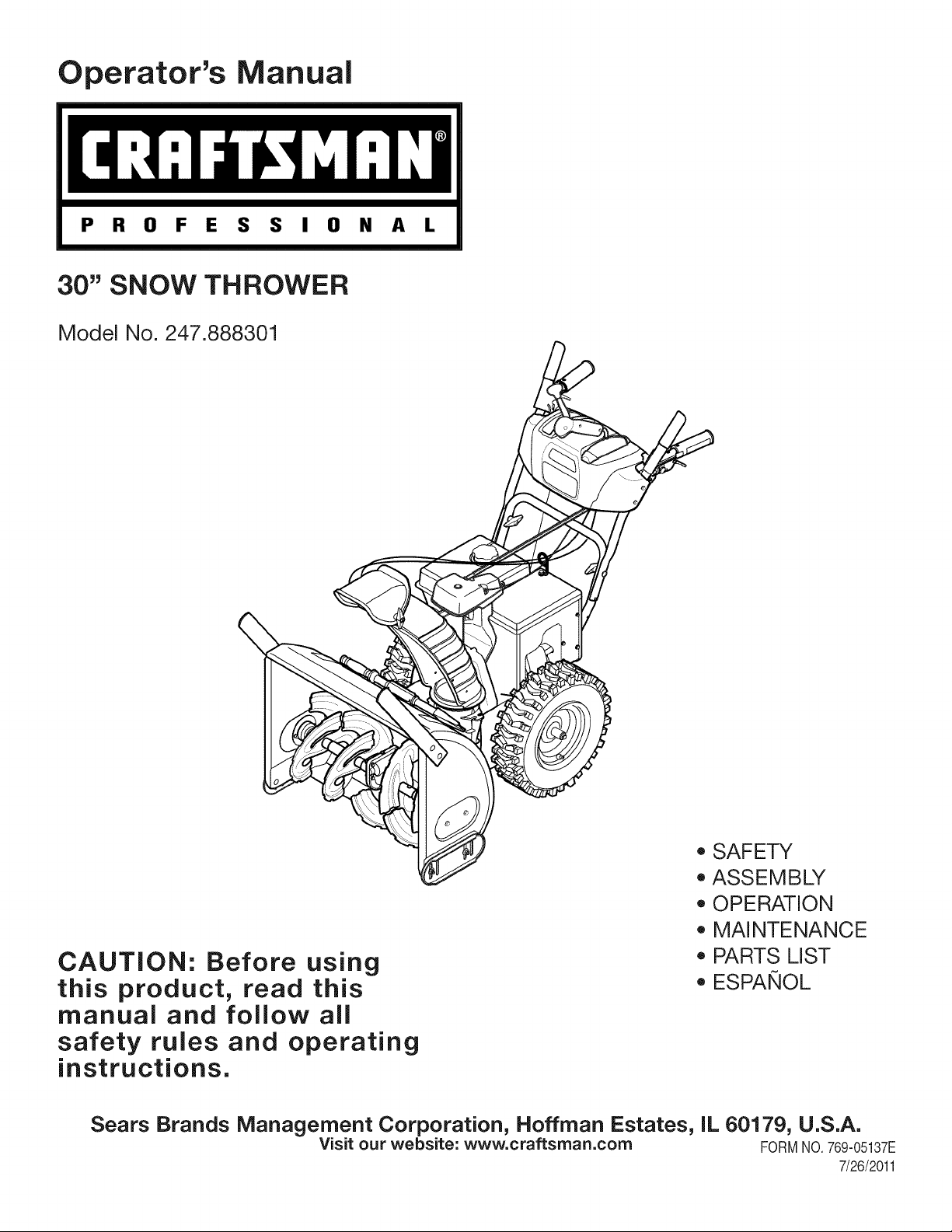
30" SNOW THROWER
Model No. 247.888301
o SAFETY
ASSEMBLY
OPERATION
MAINTENANCE
CAUTION: Before using
this product, read this
PARTS LIST
o ESPANOL
manual and follow all
safety rules and operating
instructions.
Sears Brands Management Corporation, Hoffman Estates, IL 60179, U.S.A.
Visit our website: www.craftsman.com FORM1/O.769-05137E
7/26/2011
Page 2
WarrantyStatement.................... Page2
SafeOperationPractices.............. Pages3-6
Assembly......................... Pages8-13
Operation........................ Pages14-17
Service&Maintenance.............. Pages18-23
Troubleshooting...................... Page25
PartsList......................... Pages26-41
RepairProtectionAgreement............ Page45
Espadol............................. Page46
ServiceNumbers................... BackPage
Off-SeasonStorage................... Page24
CRAFTSMANPROFESSIONAL TWO YEAR FULL WARRANTY
FORTWOYEARSfromthe dateof purchase,this productis warrantedagainstanydefectsin materialorworkmanship.Defectiveproductwill
receivefreerepairorfree replacementif repairisunavailable.
Thiswarrantyappliesforonlyone yearfromthe dateof purchaseif this productiseverusedwhileprovidingcommercialservicesorif rentedto
anotherperson.
Forwarranty coveragedetails to obtain repairor replacement,visitthe website: www.craftsman.com
This warrantycovers ONLYdefects in material andworkmanship.Warrantycoverage does not include:
• Expendableitemsthatcan wearoutfromnormalusewithinthewarrantyperiod,includingbutnotlimitedtoaugers,augerpaddles,drift
cutters,skidshoes,shaveplate,shearpins,sparkplug,aircleaner,belts,andoil filter.
• Standardmaintenanceservicing,oilchanges,or tune-ups.
• Tire replacementor repaircausedby puncturesfromoutsideobjects,suchas nails,thorns,stumps,or glass.
Tireor wheelreplacementor repairresultingfromnormalwear,accident,orimproperoperationormaintenance.
Repairsnecessarybecauseof operatorabuse,includingbutnotlimitedtodamagecausedbyover-speedingtheengine,orfromimpacting
objectsthatbendthe frame,augershaft,etc.
• Repairsnecessarybecauseof operatornegligence,includingbut notlimitedto,electricalandmechanicaldamagecausedbyimproper
storage,failureto usethepropergradeandamountofengineoil,or failureto maintaintheequipmentaccordingtotheinstructionscontained
intheoperator'smanual.
• Engine(fuelsystem)cleaningor repairscausedbyfueldeterminedto becontaminatedoroxidized(stale).Ingeneral,fuelshouldbeused
within30 daysof itspurchasedate.
Normaldeteriorationandwearof theexteriorfinishes,orproductlabelreplacement.
Thiswarrantygivesyouspecificlegalrights,andyou mayalsohaveotherrightswhichvaryfromstatetostate.
Sears Brands ManagementCorporation, HoffmanEstates, IL 60179
EngineOilType: SAE5W-30
EngineOilCapacity: 37ounces
FuelCapacity: Approx.5Quarts
SparkPlug: F6RTC
SparkPlugGap: .020"to .030"
©KCDIR LLC
ModelNumber.................................................................
Serial Number.................................................................
Dateof Purchase .............................................................
Recordthemodelnumber,serialnumber
anddateof purchaseabove
2
Page 3
Thissymbolpointsout importantsafetyinstructionswhich,if not
followed,couldendangerthepersonalsafetyand/orpropertyof
yourselfandothers. Readandfollowall instructionsin thismanual
beforeattemptingto operatethismachine.Failuretocomplywith
theseinstructionsmayresultin personalinjury.Whenyou seethis
symbol,HEEDITSWARNING!
Thismachinewasbuiltto beoperatedaccordingtothesafeopera-
tionpracticesinthis manual.Aswithanytypeof powerequipment,
carelessnessorerroron the partof theoperatorcanresultin serious
injury.Thismachineiscapableofamputatingfingers,hands,toes
andfeetandthrowingdebris.Failuretoobservethefollowingsafety
instructionscouldresultin seriousinjuryor death.
CALIFORNIA PROPOSITION 65
EngineExhaust,someof itsconstituents,andcertainvehicle
componentscontainoremitchemicalsknowntoStateofCalifornia
tocausecancerandbirthdefectsorotherreproductiveharm,
TRAiNiNG
• Read,understand,andfollowall instructionson the machineand
in themanual(s)beforeattemptingtoassembleandoperate.
Failuretodo socan resultinseriousinjurytothe operatorand/
orbystanders.Keepthismanualin a safeplaceforfutureand
regularreferenceandfororderingreplacementparts.
• Befamiliarwithall controlsandtheirproperoperation.Knowhow
tostopthe machineanddisengagethemquickly.
• Neverallowchildrenunder14yearsof agetooperatethis
machine.Children14andovershouldreadandunderstandthe
instructionsandsafeoperationpracticesin thismanualandon
themachineandbe trainedandsupervisedbyanadult.
Neverallowadultsto operatethismachinewithoutproper
instruction.
• Thrownobjectscancauseseriouspersonalinjury.Planyour
snow-throwingpatterntoavoiddischargeof materialtoward
roads,bystandersandthelike.
Keepbystanders,petsandchildrenat least75feetfromthe
machinewhileit isin operation.Stopmachineifanyoneenters
thearea.
• Exercisecautiontoavoidslippingorfalling,especiallywhen
operatinginreverse.
Your Responsibility--Restrict theuseofthispowermachineto
personswhoread,understandandfollowthewarningsandinstruc-
tionsin thismanualandon the machine,
SAVE THESE INSTRUCTIONS!
PREPARATION
Thoroughlyinspecttheareawherethe equipmentistobeused.
Removeall doormats,newspapers,sleds,boards,wiresandother
foreignobjects,whichcouldbe trippedoverorthrownbythe auger/
impeller.
• Alwayswearsafetyglassesor eyeshieldsduringoperationand
whileperformingan adjustmentor repairto protectyoureyes.
Thrownobjectswhichricochetcancauseseriousinjurytothe
eyes.
Donot operatewithoutwearingadequatewinteroutergarments.
Donot wearjewelry,longscarvesorotherlooseclothing,which
couldbecomeentangledin movingparts.Wearfootwearwhich
willimprovefootingonslipperysurfaces.
Usea groundedthree-wireextensioncordand receptaclefor all
machineswithelectricstartengines.
Disengageall controlleversbeforestartingtheengine.
Adjustcollectorhousingheightto cleargravelorcrushedrock
surfaces.
• Neverattempttomakeanyadjustmentswhileengineis running,
exceptwherespecificallyrecommendedintheoperator'smanual.
Letengineandmachineadjustto outdoortemperaturebefore
startingtoclearsnow.
3
Page 4
SafeHandling of Gasoline
Toavoidpersonalinjuryor propertydamageuseextremecarein
handlinggasoline.Gasolineisextremelyflammableandthevaporsare
explosive.Seriouspersonalinjurycan occurwhengasolineisspilled
onyourselforyourclotheswhichcan ignite.Washyourskinand
changeclothesimmediately.
• Useonlyanapprovedgasolinecontainer.
• Extinguishall cigarettes,cigars,pipesandothersources
ofignition.
• Neverfuelmachineindoors.
• Neverremovegascapor addfuelwhiletheengineis hot
or running.
• Allowengineto coolat leasttwominutesbeforerefueling.
• Neveroverfill fueltank. Filltankto no morethan1/2inch
belowbottomoffiller neckto providespaceforfuel
expansion.
• Replacegasolinecapandtightensecurely.
• Ifgasolineis spilled,wipeit offthe engineandequipment.
Movemachinetoanotherarea.Wait5 minutesbefore
startingtheengine.
• Neverstorethemachineorfuel containerinsidewhere
thereis anopenflame,sparkor pilotlight(e.g.furnace,
waterheater,spaceheater,clothesdryeretc.).
• Allowmachinetocoolat least5 minutesbeforestoring.
• Neverfillcontainersinsidea vehicleor ona truckor trailer
bedwitha plasticliner.Alwaysplacecontainersonthe
groundawayfromyourvehiclebeforefilling.
• If possible,removegas-poweredequipmentfromthetruck
ortrailerand refueliton the ground.Ifthisis notpossible,
thenrefuelsuchequipmentona trailerwitha portable
container,ratherthanfromagasolinedispensernozzle.
• Keepthenozzleincontactwiththe rimofthe fueltankor
containeropeningatalltimesuntilfuelingiscomplete.Do
notuse a nozzlelock-opendevice.
OPERATION
• Do notputhandsorfeetnear rotatingparts,in theauger/impeller
housingorchuteassembly.Contactwiththerotatingpartscan
amputatehandsandfeet.
• Theauger/impellercontrolleveris a safetydevice.Neverbypass
itsoperation.Doingsomakesthe machineunsafeandmaycause
personalinjury.
• Thecontrolleversmustoperateeasilyin bothdirectionsand
automaticallyreturntothe disengagedpositionwhenreleased.
• Neveroperatewitha missingordamagedchuteassembly.Keep
all safetydevicesinplaceandworking.
• Neverrunanengineindoorsor ina poorlyventilatedarea.Engine
exhaustcontainscarbonmonoxide,anodorlessanddeadlygas.
• Do notoperatemachinewhileunderthe influenceofalcoholor
drugs.
• Mufflerandenginebecomehotandcan causea burn.Do not
touch.Keepchildrenaway.
• Exerciseextremecautionwhenoperatingon orcrossinggravel
surfaces.Stayalertforhiddenhazardsortraffic.
• Exercisecautionwhenchangingdirectionandwhileoperatingon
slopes.Do notoperateon steepslopes.
• Planyoursnow-throwingpatternto avoiddischargetowards
windows,walls,carsetc. Thus,avoidingpossibleproperty
damageorpersonalinjurycausedby a ricochet.
• Neverdirectdischargeatchildren,bystandersand petsor allow
anyoneinfrontof themachine.
• Donot overloadmachinecapacityby attemptingtoclearsnowat
toofastof a rate.
• Neveroperatethismachinewithoutgoodvisibilityorlight.Always
be sureof yourfootingand keepa firmholdon thehandles.Walk,
neverrun.
• Disengagepowerto theauger/impellerwhentransportingor not
in use.
• Neveroperatemachineathightransportspeedsonslippery
surfaces.Lookdownand behindandusecarewhenbackingup.
• Ifthemachineshouldstartto vibrateabnormally,stopthe engine,
disconnectthesparkplugwire andgrounditagainsttheengine.
Inspectthoroughlyfordamage.Repairanydamagebefore
startingandoperating.
• Disengageall controlleversandstopenginebeforeyouleave
theoperatingposition(behindthehandles).Waituntiltheauger/
impellercomestoa completestopbeforeuncloggingthechute
assembly,makingany adjustments,or inspections.
• Neverputyourhandinthedischargeorcollectoropenings.Do
notunclogchuteassemblywhileengineis running.Shutoff
engineand remainbehindhandlesuntilall movingpartshave
stoppedbeforeunclogging.
• Useonlyattachmentsandaccessoriesapprovedbythemanufac-
turer(e.g.wheelweights,tirechains,cabsetc.).
• Whenstartingengine,pullcordslowlyuntilresistanceisfelt,then
pull rapidly.Rapidretractionofstartercord(kickback)willpull
handandarmtowardenginefasterthanyoucanletgo.Broken
bones,fractures,bruisesorsprainscouldresult.
• Ifsituationsoccurwhichare notcoveredinthis manual,usecare
andgoodjudgment.
• Forin-warrantysafety,operationor maintenancequestions,orto
orderpartsandscheduleservice,call 1-800-4-MY-HOME.
CLEARING A CLOGGED DISCHARGE CHUTE
Handcontactwiththe rotatingimpellerinsidethe dischargechute
is the mostcommoncauseofinjuryassociatedwithsnowthrowers.
Neveruseyourhandtocleanoutthedischargechute.
Toclear thechute:
1. SHUTTHEENGINEOFF!
2. Wait 10secondstobe surethe impellerbladeshavestopped
rotating.
3. Alwaysusea clean-outtool,notyourhands.
4
Page 5
MAINTENANCE & STORAGE
• Nevertamperwithsafetydevices.Checktheirproperoperation
regularly.Refertothe maintenanceandadjustmentsectionsof
thismanual.
• Beforecleaning,repairing,or inspectingmachinedisengageall
controlleversandstoptheengine.Waituntiltheauger/impeller
cometoa completestop.Disconnectthe sparkplugwireand
groundagainsttheengineto preventunintendedstarting.
Checkboltsand screwsforpropertightnessatfrequentintervals
tokeepthemachineinsafeworkingcondition.Also,visually
inspectmachineforanydamage.
Donotchangetheenginegovernorsettingorover-speedthe
engine.Thegovernorcontrolsthe maximumsafeoperatingspeed
ofthe engine.
Snowthrowershaveplatesandskidshoesaresubjecttowear
anddamage.Foryoursafetyprotection,frequentlycheckall
componentsand replacewithoriginalequipmentmanufacturer's
(OEM)partsonlyaslistedinthe Partspagesof thisoperator's
manual.Useofpartswhichdonot meettheoriginalequipment
specificationsmayleadto improperperformanceandcompro-
misesafety!
Checkcontrolleversperiodicallytoverifytheyengageanddisen-
gageproperlyandadjust,ifnecessary.Refertotheadjustment
sectioninthisoperator'smanualforinstructions.
Maintainor replacesafetyandinstructionlabels,as necessary.
Observeproperdisposallawsand regulationsforgas,oil,etc.to
protecttheenvironment.
Priorto storing,runmachinea few minutestoclearsnowfrom
machineand preventfreezeupofauger/impeller.
Neverstorethemachineorfuel containerinsidewherethereisan
openflame,sparkorpilot lightsuchas a waterheater,furnace,
clothesdryeretc.
Alwaysrefertothe operator'smanualforproperinstructionson
off-seasonstorage.
Checkfuelline,tank, cap,andfittingsfrequentlyfor cracksor
leaks.Replaceif necessary.
Donotcrankenginewithsparkplugremoved.
Accordingtothe ConsumerProductsSafetyCommission(CPSC)
andtheU.S.EnvironmentalProtectionAgency(EPA),thisproduct
hasan AverageUsefulLifeof seven(7)years,or 60 hoursof
operation.Atthe endoftheAverageUsefulLifehavethemachine
inspectedannuallybyan authorizedservicedealertoensurethat
allmechanicalandsafetysystemsareworkingproperlyand not
wornexcessively.Failureto do socan resultinaccidents,injuries
ordeath.
DO NOT MODIFY ENGINE
Toavoidseriousinjuryor death,do not modifyengineinany way.
Tamperingwiththegovernorsettingcanleadtoa runawayengineand
causeitto operateat unsafespeeds.Nevertamperwithfactorysetting
ofenginegovernor.
NOTICE REGARDING EMiSSiONS
EngineswhicharecertifiedtocomplywithCaliforniaandfederal
EPAemissionregulationsfor SORE(SmallOff RoadEquipment)are
certifiedto operateonregularunleadedgasoline,and mayinclude
thefollowingemissioncontrolsystems:EngineModification(EM),
OxidizingCatalyst(OC),SecondaryAirInjection(SAI)and ThreeWay
Catalyst(TWO)if soequipped.
SPARK ARRESTOR
Thismachineisequippedwithaninternalcombustionengineand
shouldnotbe usedonor nearany unimprovedforest-covered,
brush-coveredorgrass-coveredlandunlessthe engine'sexhaust
systemisequippedwitha sparkarrestormeetingapplicablelocalor
statelaws(if any)
Ifa sparkarrestorisused,it shouldbe maintainedin effectiveworking
orderbytheoperator.Inthe StateofCaliforniatheaboveisrequired
bylaw (Section4442ofthe CaliforniaPublicResourcesCode).Other
statesmayhavesimilarlaws. Federallawsapplyonfederallands.
A sparkarrestorforthe muffleris availablethroughyournearestSears
PartsandRepairServiceCenter.
Page 6
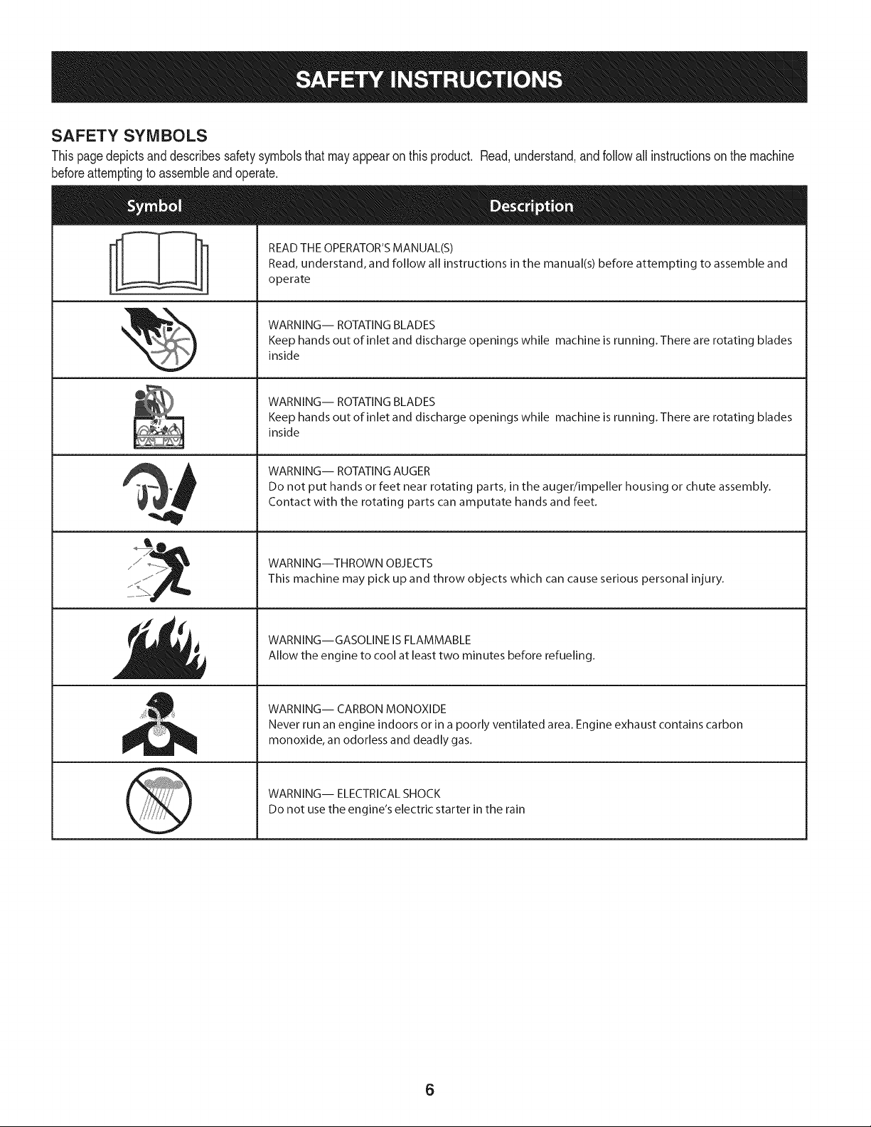
SAFETY SYMBOLS
Thispagedepictsanddescribessafetysymbolsthatmayappearonthisproduct. Read,understand,andfollowallinstructionson themachine
beforeattemptingto assembleandoperate.
READ THE OPERATOR'S MANUAL(S)
i
. +
i
Read, understand, and follow all instructions in the manual(s) before attempting to assemble and
operate
WARNING-- ROTATING BLADES
Keep hands out of inlet and discharge openings while machine is running. There are rotating blades
inside
WARNING-- ROTATING BLADES
Keep hands out of inlet and discharge openings while machine is running. There are rotating blades
inside
WARNING-- ROTATING AUGER
Do not put hands or feet near rotating parts, in the auger/impeller housing or chute assembly.
Contact with the rotating parts can amputate hands and feet.
"JIp
WARNING--THROWN OBJECTS
This machine may pick up and throw objects which can cause serious personal injury.
WARNING--GASOLINE IS FLAMMABLE
Allow the engine to cool at least two minutes before refueling.
WARNING-- CARBON MONOXIDE
Never run an engine indoors or in a poorly ventilated area. Engine exhaust contains carbon
monoxide, an odorless and deadly gas+
WARNING-- ELECTRICAL SHOCK
Do not use the engine's electric starter in the rain
6
Page 7

Thispageleftintentionallyblank.
7
Page 8
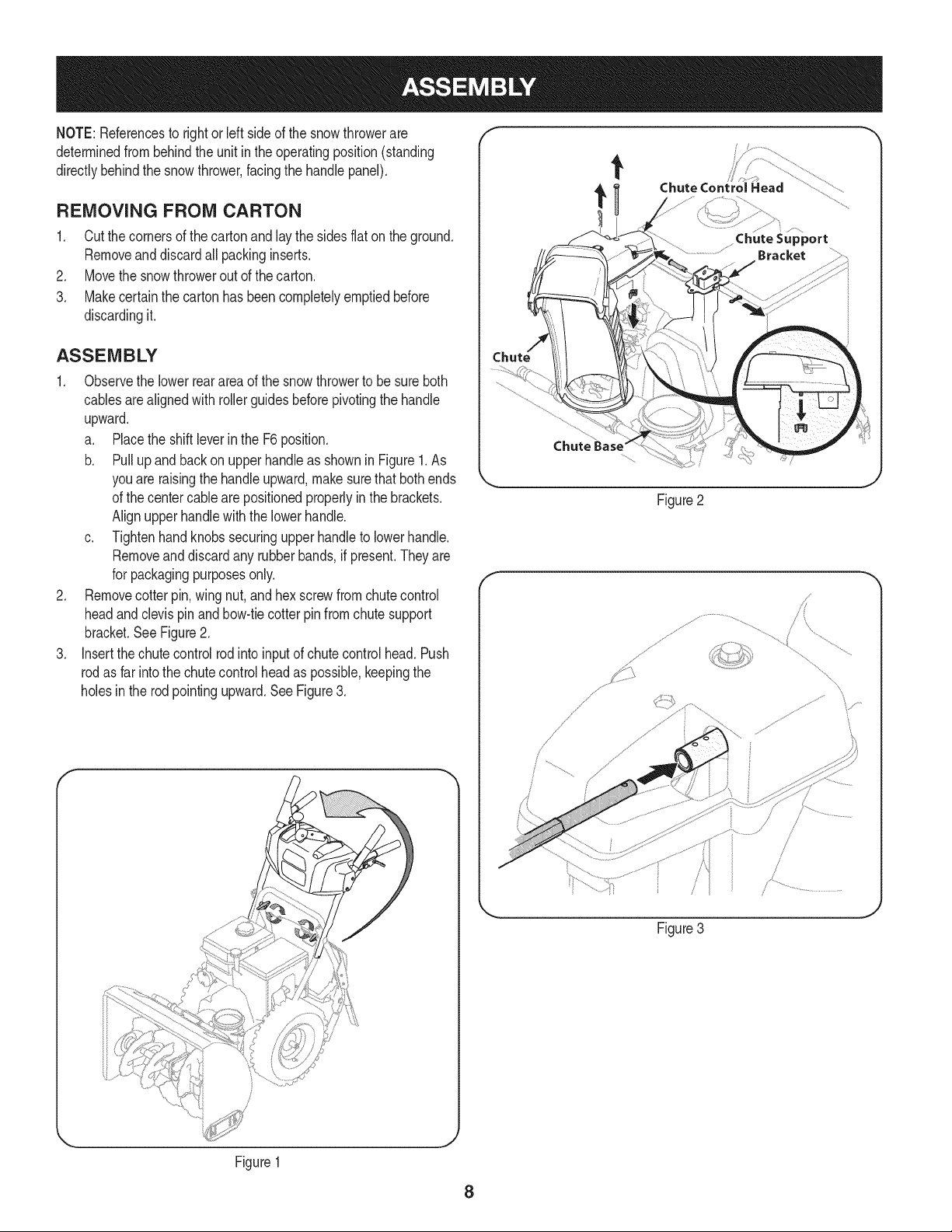
NOTE:Referencesto rightorleft sideof thesnowthrowerare
determinedfrombehindtheunit intheoperatingposition(standing
directlybehindthesnowthrower,facingthe handlepanel).
REMOVING FROM CARTON
1. Cutthecornersof thecartonandlay thesidesflaton the ground.
Removeanddiscardallpackinginserts.
2. Movethesnowthrowerout ofthecarton.
3. Makecertainthecartonhas beencompletelyemptiedbefore
discardingit.
ASSEMBLY
1. Observethe lowerrearareaofthe snowthrowertobesure both
cablesarealignedwith rollerguidesbeforepivotingthehandle
upward.
a. Placethe shiftleverin theF6position.
b. Pullupandbackon upperhandleasshownin Figure1.As
youare raisingthehandleupward,makesurethat bothends
ofthe centercablearepositionedproperlyinthebrackets.
Alignupperhandlewiththelowerhandle.
c. Tightenhandknobssecuringupperhandletolowerhandle.
Removeanddiscardany rubberbands,ifpresent.Theyare
forpackagingpurposesonly.
2. Removecotterpin,wing nut,andhexscrewfromchutecontrol
headandclevispinandbow-tiecotterpinfromchutesupport
bracket.SeeFigure2.
3. Insertthechutecontrolrodintoinputofchutecontrolhead.Push
rodasfar intothe chutecontrolheadaspossible,keepingthe
holesin the rodpointingupward.SeeFigure3.
t
Chute Control Head
Chute
Figure2
f
// .....
%
Figure1
Figure3
8
Page 9
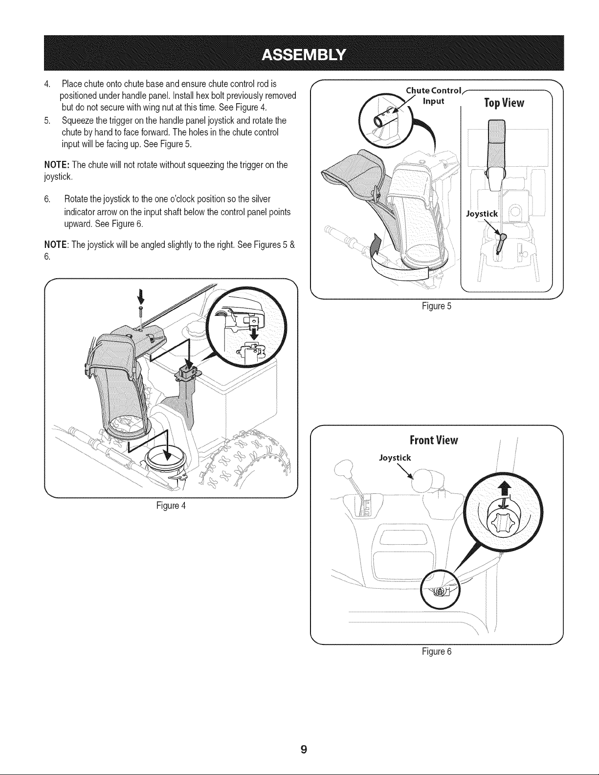
4. Placechuteontochutebaseandensurechutecontrolrodis
positionedunderhandlepanel.Installhexboltpreviouslyremoved
butdo notsecurewithwingnutatthistime.See Figure4.
5. Squeezethetriggeron the handlepaneljoystickandrotatethe
chutebyhandto faceforward.Theholesinthe chutecontrol
inputwill befacingup.SeeFigure5.
NOTE:The chutewillnot rotatewithoutsqueezingthe triggeronthe
joystick.
6. Rotatethejoystickto theoneo'clockpositionsothesilver
indicatorarrowonthe inputshaft belowthecontrolpanelpoints
upward.SeeFigure6.
NOTE:Thejoystickwillbe angledslightlyto theright.SeeFigures5 &
6.
TopView
Figure5
Figure4
f
FrontView
Joystick
J
Figure6
9
Page 10
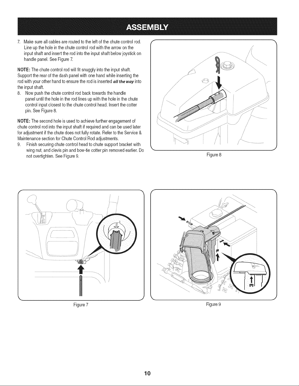
. Makesureallcablesareroutedtotheleft of thechutecontrolrod.
Lineuptheholein thechutecontrolrodwiththearrowonthe
inputshaftandinsertthe rodintotheinputshaftbelowjoystickon
handlepanel.SeeFigure7.
NOTE:Thechutecontrolrodwillfit snugglyintotheinputshaft.
Supporttherearofthedashpanelwithone handwhileinsertingthe
rodwithyourotherhandto ensuretherodis insertedall the way into
theinput shaft.
8. Nowpushthechutecontrolrodbacktowardsthehandle
paneluntilthe holein therodlinesupwiththe holein the chute
controlinputclosestto thechutecontrolhead. Insertthecotter
pin.SeeFigure8.
NOTE:The secondholeis usedtoachievefurtherengagementof
chutecontrolrodintothe inputshaftif requiredandcan be usedlater
foradjustmentifthechutedoes notfullyrotate.RefertotheService&
MaintenancesectionforChuteControlRodadjustments.
9. Finishsecuringchutecontrolheadto chutesupportbracketwith
wingnut,andclevispinandbow-tiecotterpinremovedearlier.Do
notovertighten.SeeFigure9.
/
.J
Figure8
y..................
\
Figure7
Figure9
10
Page 11
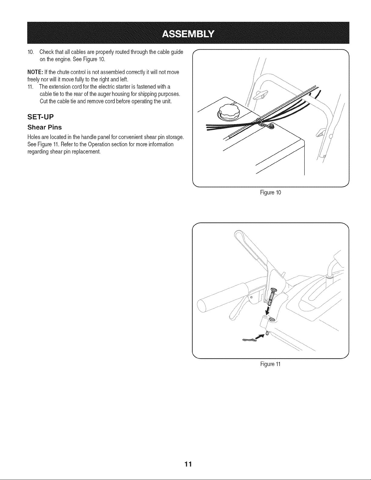
10. Checkthatallcablesareproperlyroutedthroughthecable guide "_
on theengine.SeeFigure10.
NOTE:if thechutecontrolis notassembledcorrectlyitwill notmove
freelynorwillit movefullyto therightandleft.
11. Theextensioncordfortheelectricstarterisfastenedwitha
cabletie to the rearofthe augerhousingforshippingpurposes.
Cutthecabletieand removecordbeforeoperatingthe unit.
SET-UP
Shear Pins
Holesare locatedinthehandlepanelfor convenientshearpin storage.
SeeFigure11.Refertothe Operationsectionformoreinformation
regardingshearpin replacement.
f
/
Figure10
11
J
Figure11
Page 12
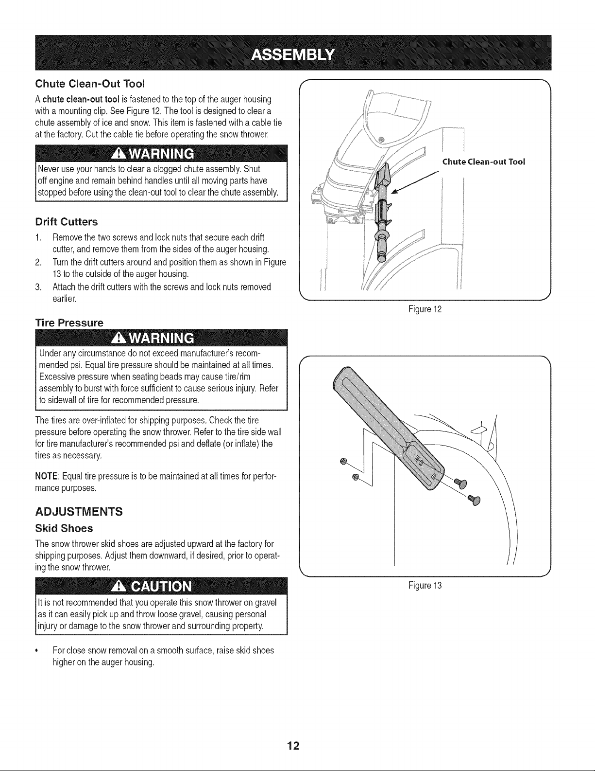
Chute Clean-Out Tool
Achute clean-out tool isfastenedtothetopoftheaugerhousing
witha mountingclip.SeeFigure12.Thetool isdesignedtocleara
chuteassemblyofice andsnow.Thisitemis fastenedwitha cabletie
atthe factory.Cutthecabletie beforeoperatingthesnowthrower.
loft _1 .allmovingpartshave
stoppedbeforeusingtheclean-outtooltoclearthechuteassembly.
Drift Cutters
1. Removethetwo screwsand locknutsthatsecureeachdrift
cutter,andremovethemfromthesidesof theaugerhousing.
2. TurnthedriftcuttersaroundandpositionthemasshowninFigure
13tothe outsideoftheaugerhousing.
3. Attachthedrift cutterswiththescrewsandlocknutsremoved
earlier.
Tire Pressure
Underanycircumstancedo notexceedmanufacturer'srecom-
mendedpsi.Equaltirepressureshouldbemaintainedat all times.
Excessivepressurewhenseatingbeadsmaycausetire/rim
assemblytoburstwithforcesufficienttocauseseriousinjury.Refer
tosidewallof tirefor recommendedpressure.
Chutedean-out Tool
Figure12
Thetiresareover-inflatedforshippingpurposes.Checkthetire
pressurebeforeoperatingthesnowthrower.Refertothetiresidewall
fortiremanufacturer'srecommendedpsianddeflate(orinflate)the
tiresasnecessary.
NOTE:Equaltire pressureisto be maintainedat alltimesforperfor-
mancepurposes.
ADJUSTMENTS
Skid Shoes
Thesnowthrowerskidshoesareadjustedupwardatthefactoryfor
shippingpurposes.Adjustthemdownward,ifdesired,priortooperat-
ingthesnowthrower.
It isnot recommendedthatyouoperatethissnowthrowerongravel
asitcaneasilypickup andthrowloosegravel,causingpersonal
njuryordamageto the snowthrowerand surroundng property.
• Forclosesnowremovalona smoothsurface,raiseskidshoes
higherontheaugerhousing.
Figure13
12
Page 13
Usea middleorlowerpositionwhentheareatobe clearedis
uneven,suchasa graveldriveway.
NOTE:Ifyou choosetooperatethesnowthroweron agravelsurface,
keepthe skidshoesin positionformaximumclearancebetweenthe
groundandtheshaveplate.
Operatinga snowthrowerequippedwithsteelskidshoesmayresult
indamageto naturalstonepaversurfaces(e.g.sandstone,blue-
stone,limestone).Forinformationonavailablepolymerskidshoes,
call1-800-4MY-HOME.
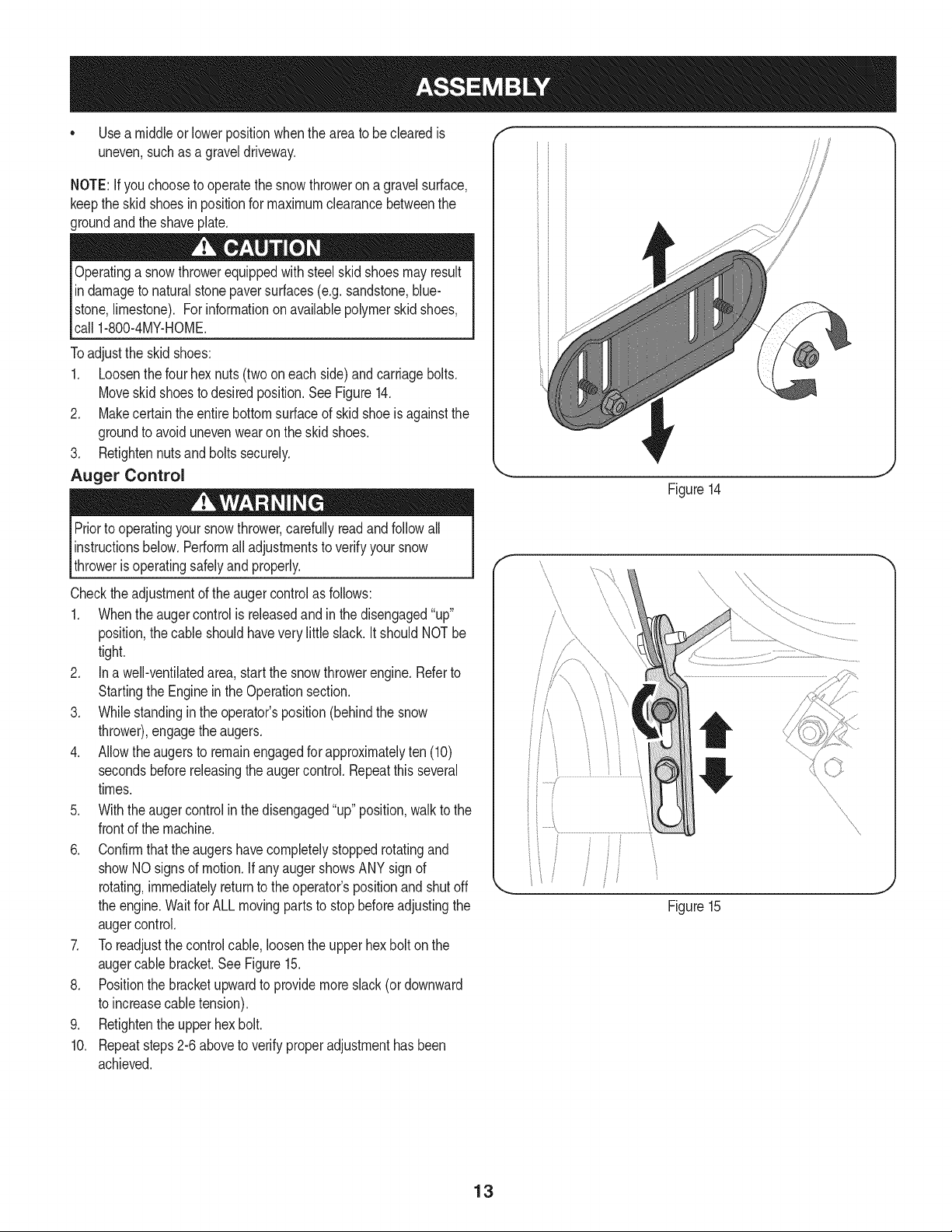
Toadjustthe skidshoes:
1. Loosenthefourhexnuts(twooneachside)andcarriagebolts.
Moveskidshoestodesiredposition.SeeFigure14.
2. Makecertaintheentirebottomsurfaceof skidshoeisagainstthe
groundtoavoidunevenwearontheskidshoes.
3. Retightennutsandboltssecurely.
Auger Control
Priortooperatingyoursnowthrower,carefullyreadandfollowall
instructionsbelow.Performalladjustmentstoverifyyoursnow
throwerisoperatingsafelyandproperly.
J
Figure14
f
Checktheadjustmentofthe augercontrolasfollows:
1. Whentheaugercontrolis releasedandinthedisengaged"up"
position,thecableshouldhaveverylittleslack.ItshouldNOTbe
tight.
2. Ina well-ventilatedarea,start thesnowthrowerengine.Referto
StartingtheEngineinthe Operationsection.
3. Whilestandinginthe operator'sposition(behindthe snow
thrower),engagethe augers.
4. Allowtheaugersto remainengagedforapproximatelyten (10)
secondsbeforereleasingthe augercontrol.Repeatthisseveral
times.
5. Withtheaugercontrolin thedisengaged"up" position,walktothe
frontofthe machine.
6. Confirmthatthe augershavecompletelystoppedrotatingand
showNOsignsof motion.IfanyaugershowsANYsignof
rotating,immediatelyreturntothe operator'spositionandshutoff
theengine.WaitforALLmovingpartsto stopbeforeadjustingthe
augercontrol.
7. Toreadjustthecontrolcable,loosentheupperhexbolt onthe
augercablebracket.SeeFigure15.
8. Positionthebracketupwardtoprovidemoreslack(or downward
toincreasecabletension).
9. Retightentheupperhexbolt.
10. Repeatsteps2-6aboveto verifyproperadjustmenthasbeen
achieved.
f
/
J
Figure15
13
Page 14
f
Drive Control
Headlight
Shift Lever
J _ Four-Way Chute ControP (Joystick)
//_ ...................AugerControl.
Gas Cap
\
Chute Assembly
Drift Cutter _ --
\
\
\
\\\\\
t
iFi
Augers
Skid Shoe Oil Drain
Figure15
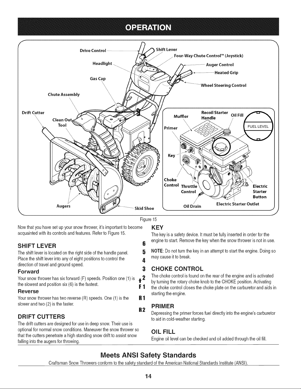
Nowthat youhavesetup yoursnowthrower,it'simportanttobecome
acquaintedwith itscontrolsandfeatures.Referto Figure15.
SHIFT LEVER 6
Theshiftleverislocatedonthe rightsideof thehandlepanel. 5
Placethe shiftleverintoanyof eightpositionstocontrolthe 4
directionoftravelandgroundspeed,
Forward 3
Yoursnowthrowerhassixforward(F) speeds.Positionone(1)is t 2
theslowestandpositionsix(6) is thefastest. F 1
Reverse
Yoursnowthrowerhastwo reverse(R)speeds.One(1)is the
slowerandtwo(2) isthe faster.
DRIFT CUTTERS
Thedrift cuttersaredesignedforuse indeepsnow.Theiruseis
optionalfornormalsnowconditions.Maneuverthe snowthrowerso
thatthecutterspenetrateahighstandingsnowdrifttoassistsnow
fallingintotheaugersforthrowing.
y Muffler Handle OilFill
Primer \
Choke
KEY
Thekeyis a safetydevice.It mustbefullyinsertedinorderforthe
engineto start.Removethekeywhenthesnowthroweris notinuse.
NOTE:Donotturnthekeyinan attemptto startthe engine.Doingso
maycauseit to break.
CHOKE CONTROL
Thechokecontrolis foundon the rearofthe engineand isactivated
byturningtherotarychokeknobtotheCHOKEposition.Activating
thechokecontrolclosesthechokeplateonthecarburetorandaidsin
startingthe engine.
PRIMER
Depressingthe primerforcesfueldirectlyintotheengine'scarburetor
toaid incold-weatherstarting.
OIL FILL
Engineoil levelcan becheckedandoiladdedthroughtheoil fill.
Meets ANSi Safety Standards
CraftsmanSnowThrowersconformtothe safetystandardofthe AmericanNationalStandardsInstitute(ANSI).
14
Page 15
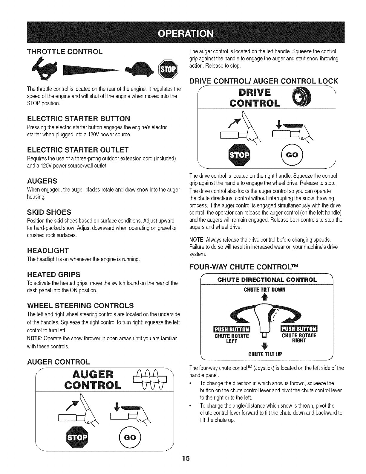
THROTTLE CONTROL
Thethrottlecontrolis locatedonthe rearofthe engine.It regulatesthe
speedof theengineandwill shutoff theenginewhenmovedintothe
STOPposition.
ELECTRIC STARTER BUTTON
Pressingtheelectricstarterbuttonengagestheengine'selectric
starterwhenpluggedintoa 120Vpowersource.
ELECTRIC STARTER OUTLET
Requirestheuseof athree-prongoutdoorextensioncord(included)
anda 120Vpowersource/walloutlet.
AUGERS
Whenengaged,theaugerbladesrotateanddrawsnowintotheauger
housing.
SKID SHOES
Positiontheskid shoesbasedon surfaceconditions.Adjustupward
forhard-packedsnow.Adjustdownwardwhenoperatingon gravelor
crushedrocksurfaces.
HEADLIGHT
Theheadlightison whenevertheengineisrunning.
HEATED GRIPS
Toactivatethe heatedgrips,movetheswitchfoundon the rearofthe
dashpanelintotheON position.
WHEEL STEERING CONTROLS
Theleft andrightwheelsteeringcontrolsarelocatedon theunderside
ofthe handles.Squeezethe rightcontrolto turnright;squeezetheleft
controltoturn left.
NOTE:Operatethesnowthrowerinopenareasuntilyouarefamiliar
withthesecontrols.
Theaugercontrolis locatedon thelefthandle.Squeezethe control
gripagainstthehandleto engagetheaugerand startsnowthrowing
action.Releaseto stop.
DRIVE CONTROL/AUGER CONTROL LOCK
DRIVE
CONTROL
Thedrivecontrolis locatedonthe righthandle.Squeezethecontrol
gripagainstthehandleto engagethewheeldrive.Releasetostop.
Thedrivecontrolalsolockstheaugercontrolso youcan operate
thechutedirectionalcontrolwithoutinterruptingthesnowthrowing
process.If theaugercontrolis engagedsimultaneouslywiththe drive
control,the operatorcan releasetheaugercontrol(onthelefthandle)
andtheaugerswillremainengaged.Releaseboth controlstostopthe
augersandwheeldrive.
NOTE:Alwaysreleasethedrivecontrolbeforechangingspeeds.
Failureto dosowillresultinincreasedwearonyourmachine'sdrive
system.
FOUR=WAY CHUTE CONTROL TM
CHUTE DiRECTiONAL CONTROL
CHUTETiLTDOWN
t
CHUTEROTATE CHUTEROTATE
LEFT RIGHT
AUGER CONTROL
CHUTETiLTUP
Thefour-waychutecontrolTM (Joystick)islocatedon theleftsideofthe
handlepanel.
* Tochangethedirectioninwhichsnowisthrown,squeezethe
buttononthechutecontrolleverand pivotthechutecontrollever
tothe rightortotheleft.
* Tochangetheangle/distancewhichsnowisthrown,pivotthe
chutecontrolleverforwardto tiltthechutedownand backwardto
tilt thechuteup.
15
j,
Page 16
CLEAN-OUT TOOL
Neveruseyourhandsto cleara cloggedchuteassembly.Shut
loft engineand remainbehindhandlesuntilallmovingpartshave
lstoppedbeforeusingtheclean-outtool toclearthechuteassembly.
Thechuteclean-outtoolisconvenientlyfastenedtotherearofthe
augerhousingwitha mountingclip.Shouldsnowandice become
lodgedin thechuteassemblyduringoperation,proceedasfollowsto
safelycleanthechuteassemblyandchuteopening:
1. Releaseboththe AugerControlandtheDriveControl.
2. Stopthe enginebyremovingtheignitionkey.
3. Removetheclean-outtoolfromthe clipwhichsecuresitto the
rearofthe augerhousing.
4. Usetheshovel-shapedendof theclean-outtoolto dislodgeand
scoopanysnowand icewhichhasformedin andnearthechute
assembly.
5. Refastentheclean-outtooltothe mountingcliponthe rearof
theaugerhousing,reinserttheignitionkeyandstartthesnow
thrower'sengine.
6. Whilestandinginthe operator'sposition(behindthesnow
thrower),engagethe augercontrolfora fewsecondstoclear any
remainingsnowandice fromthechuteassembly.
BEFORE STARTING ENGINE
Read,understand,andfollowall instructionsandwarningson the
machineand inthismanualbeforeoperating.
Oil
Theunit wasshippedwith oil inthe engine.Checkoillevelbefore
eachoperationtoensureadequateoilintheengine.Forfurther
instructions,refertothe stepson page18.
NOTE:Besuretochecktheengineon a levelsurfacewiththeengine
stopped.
1. Removetheoil fillercap/dipstickandwipethedipstickclean.
2. insertthecap/dipstickintothe oilfillerneck,andtightenthecap
untilseated.
3. Removetheoil fillercap/dipstick,ifthe levelislow,slowlyadd
oil (5%30, witha minimumclassificationof SF/SG)untiloil level
registersbetweenhigh(H) andlow(L).
NOTE:Do notoverfill.Overfillingwithoil mayresultinenginesmoking,
hardstartingorsparkplugfouling.
4. Replaceandtightencap/dipstickfirmlybeforestartingengine.
Gasoline
Useautomotivegasoline(unleadedor low leadedtominimizecombus-
tionchamberdeposits)witha minimumof87octane.Gasolinewith
upto 10%ethanolor 15%MTBE(MethylTertiaryButylEther)canbe
used.Neveruseanoil/gasolinemixtureor dirtygasoline.Avoidgetting
dirt,dust,or waterinthefueltank. DONOTuse E85gasoline.
• Refuelina well-ventilatedareawiththeenginestopped.Donot
smokeorallowflamesor sparksin theareawheretheengineis
refueledor wheregasolineisstored.
• Donot overfillthefueltank.After refueling,makesurethetank
capis closedproperlyandsecurely.
• Becarefulnotto spillfuelwhenrefueling.Spilledfuelorfuelvapor
mayignite,ifanyfuelisspilled,makesuretheareaisdrybefore
startingthe engine.
• Avoidrepeatedorprolongedcontactwithskinor breathingof
)or.
Useextremecarewhenhandlinggasoline.Gasolineisextremely
flammableandthevaporsare explosive.Neverfuelthe machine
indoorsorwhiletheengineis hotor running.Extinguishcigarettes,
cigars,pipesandothersourcesof ignition.
1. Cleanaroundfuelfillbeforeremovingcaptofuel.
2. A fuellevelindicatorislocatedinthefueltank.SeeFigure15
inset.Becarefulnottooverfill.Filltank untilfuelreachesthefuel
levelindicatortoallowspacefor fuelexpansion.
STARTING THE ENGINE
Alwayskeephandsandfeetclearof movingparts.Donot usea
pressurizedstartingfluid.Vaporsareflammable.
NOTE:Allowtheengineto warmupfora fewminutesafter starting.
Theenginewill notdevelopfullpoweruntilit reachesoperating
temperatures.
1. Makecertainboththe augercontrolanddrivecontrolarein the
disengaged(released)position.
2. insertkeyintoslot.Makesureitsnapsintoplace.Donotattempt
toturn thekey.
NOTE:Theenginecannotstartwithoutthekeyfullyinsertedintothe
ignitionswitch.
Electric Starter
Theoptionalelectricstarterisequippedwitha groundedthree-wire
powercordandplug,and is designedto operateon120voltAC
householdcurrent.It mustbeusedwitha properlygroundedthree-
prongreceptacleat all timesto avoidthe possibilityofelectricshock.
Followall instructionscarefullypriortooperatingtheelectricstarter.
DONOTuse electricstarterintherain.
Determinethatyourhome'swiringisa three-wiregroundedsystem.
Aska licensedelectricianifyouarenotcertain.
Ifyouhavea groundedthree-prongreceptacle,proceedasfollows.
Ifyoudonot havethe properhousewiring,DONOTusethe electric
starterunderanyconditions.
1. Plugtheextensioncordintotheoutletlocatedonthe engine's
surface.Plugtheotherendof extensioncordintoathree-prong
120-volt,grounded,ACoutletina well-ventilatedarea.
16
Page 17
2. Movethrottlecontrolto FAST(rabbit)'_ position.
3. Movechoketothe CHOKEIJl position(coldenginestart).If
engineiswarm,placechokein RUNposition.
4. Pushprimerthree(3)times,makingsuretocoverventholein
primerbulbwhen pushing.If engineiswarm,pushprimeronly
once.Alwayscoverventholewhenpushing.Coolweathermay
requireprimingtobe repeated.
5. Pushstarterbuttontostart engine.Oncetheenginestarts,im-
mediatelyreleasestarterbutton.Electricstarterisequippedwith
thermaloverloadprotection;systemwilltemporarilyshut-downto
allowstartertocool ifelectricstarterbecomesoverloaded.
6. Astheenginewarms,slowlyrotatethe chokecontroltoRUN
position.Ifthe enginefalters,restartengineandrunwithchoke
athalf-chokepositionfora shortperiodof time,andthen slowly
rotatethechokeinto RUNposition.
7. Afterengineisrunning,disconnectpowercordfromelectric
starter.Whendisconnecting,alwaysunplugtheendatthewall
outletbeforeunpluggingtheoppositeendfromtheengine.
Recoil Starter
Donotpullthestarterhandlewhilethe enginerunning.
1. Movethrottlecontrolto FAST(rabbit)'_ position.
2. Movechoketothe CHOKEI,'_1 position(coldenginestart).If
engineiswarm,placechokein RUNposition.
3. Pushprimerthree(3)times,makingsuretocoverventholewhen
pushing.Ifengineiswarm,pushprimeronlyonce.Alwayscover
ventholewhenpushing.Coolweathermayrequireprimingtobe
repeated.
4. Pullgentlyonthe starterhandleuntilit beginsto resist,then
pullquicklyandforcefullytoovercomethe compression.Engine
shouldstart.Donotreleasethehandleandallowittosnapback.
ReturnropeSLOWLYto originalposition.If required,repeatthis
step.
5. Astheenginewarms,slowlyrotatethe chokecontroltoRUN
position.Ifthe enginefalters,restartengineandrunwithchoke
athalf-chokepositionfora shortperiodof time,andthen slowly
rotatethechokeinto RUNposition.
TO ENGAGE DRIVE
1. Withthethrottlecontrolinthe Fast(rabbit)position,moveshift
leverintooneofthe sixforward(F)positionsor tworeverse(R)
positions.Selecta speedappropriateforthe snowconditionsand
a paceyou'recomfortablewith.
NOTE:When selectinga DriveSpeed,usetheslowerspeedsuntil
youarecomfortableandfamiliarwiththe operationofthesnow
thrower.
2. Squeezethedrivecontrolagainstthehandleandthesnow
throwerwillmove.Releaseitanddrive motionwillstop.
NOTE:NEVERrepositionthe shiftlever(changespeedsordirection
oftravel)withoutfirstreleasingthedrivecontrolandbringingthesnow
throwertoa completestop.Doingsowill resultin prematurewearto
thesnowthrower'sdrivesystem.
TO ENGAGE AUGER
1. Toengagetheaugerand startthrowingsnow,squeezetheauger
controlagainsttheleft handle.Releasetostopthe auger.
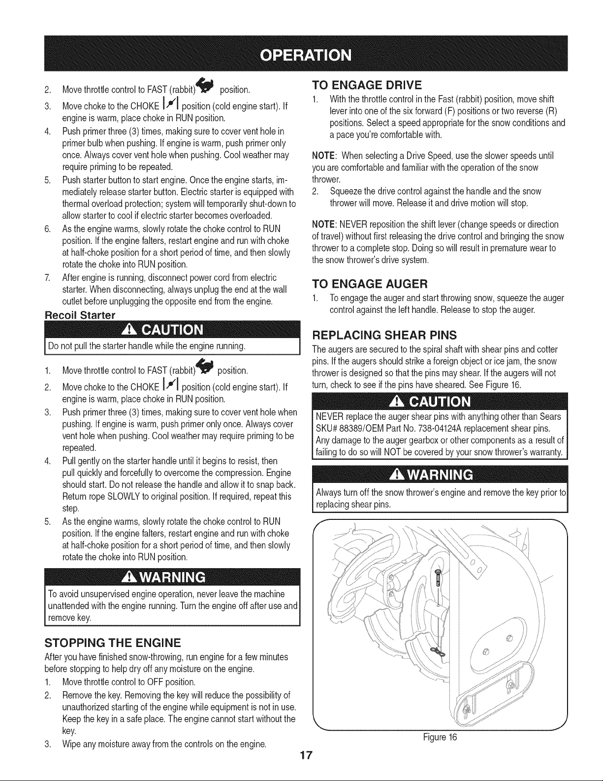
REPLACING SHEAR PiNS
Theaugersare securedtothe spiralshaftwith shearpinsandcotter
pins.If theaugersshouldstrikeaforeignobjectorice jam,thesnow
throwerisdesignedsothatthe pinsmayshear.If theaugerswill not
turn,checkto seeif thepins havesheared.SeeFigure16.
NEVERreplacetheaugershearpinswithanythingotherthanSears
SKU#88389/0EM PartNo.738-04124Areplacementshearpins.
Anydamagetotheaugergearboxorothercomponentsasa resultof
failingto do sowill NOTbecoveredbyyoursnowthrower'swarranty.
Alwaysturnoff thesnowthrower'sengineand removethekeypriorto
replacingshearpins.
if -,
Toavoidunsupervisedengineoperation,neverleavethemachine
unattendedwiththeenginerunning.Turntheengineoffafteruseand
removekey.
STOPPING THE ENGINE
Afteryouhavefinishedsnow-throwing,runengineforafew minutes
beforestoppingtohelpdryoffany moistureonthe engine.
1. MovethrottlecontroltoOFFposition.
2. Removethekey.Removingthekeywill reducethepossibilityof
unauthorizedstartingoftheenginewhileequipmentisnotinuse.
Keepthekeyina safeplace.The enginecannotstartwithoutthe
key.
3. Wipeanymoistureawayfromthe controlsontheengine.
\
J
//
Figure16
17
Page 18
MAINTENANCE SCHEDULE
Beforeperforminganytypeofmaintenance/service,disengageall
controlsandstoptheengine.Waituntilallmovingpartshavecometo
acompletestop.Disconnectsparkplugwireandgroundit againstthe
enginetopreventunintendedstarting.Alwayswearsafetyglassesduring
operationorwhileperforminganyadjustmentsorrepairs.
EachUseandevery5
hours
1st5 hours
Annuallyor25 hours
Annuallyor50 hours
Annuallyor100hours
BeforeStorage
1. Engineoil level
2. Looseor missinghardware
3. Unitandengine.
1. Engineoil
1. Sparkplug
2. Controllinkagesandpivots
3. Wheels
4. GearshaftandAugershaft
1. Engineoil
1. Sparkplug
1. Fuelsystem
1. Check
2. Tightenor replace
3. Clean
1. Change
1. Check
2. Lubewithlightoil
3. Lubewithmultipurposeautogrease
4. Lubewithlightoil
1. Change
1. Change
1. Runengineuntilit stopsfromlack
ENGINE MAINTENANCE
Checking Engine Oil
Followthemaintenanceschedulegivenbelow.Thischartdescribes
serviceguidelinesonly.UsetheServiceLogcolumntokeeptrackof
completedmaintenancetasks.Tolocate the nearest Sears Service
Centeror to scheduleservice,simplycontactSearsat
1-800-4-MY-HOME®.
d fuel
Beforelubricating,repairing,or inspecting,disengageall controls
Iandstopengine.Waituntilall movingpartshavecometo a complete
_stop.
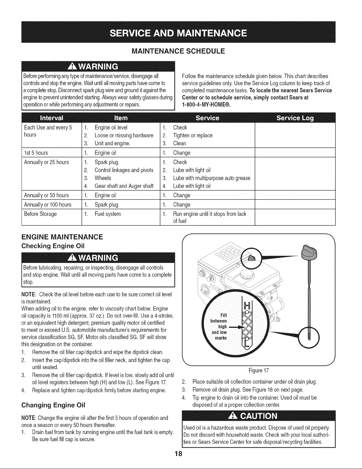
NOTE: Checktheoil levelbeforeeachuseto besurecorrectoil level
ismaintained.
Whenaddingoilto theengine,referto viscositychart below.Engine
oilcapacityis 1100ml(approx.37oz.).Donotover-fill.Usea 4-stroke,
oran equivalenthighdetergent,premiumqualitymotoroilcertified
tomeetorexceedU.S.automobilemanufacturer'srequirementsfor
serviceclassificationSG, SRMotoroilsclassifiedSG,SFwillshow
thisdesignationonthecontainer.
1. Removetheoil fillercap/dipstickandwipethedipstickclean.
2. Insertthe cap/dipstickintothe oilfillerneck,andtightenthecap
untilseated.
3. Removetheoil fillercap/dipstick.Iflevelis low,slowlyaddoiluntil
oil levelregistersbetweenhigh(H)andlow (L).SeeFigure17.
4. Replaceandtightencap/dipstickfirmlybeforestartingengine.
Changing Engine Oil
NOTE:Changetheengineoilafterthe first5 hoursof operationand
oncea seasonorevery50 hoursthereafter.
1. Drainfuelfromtankbyrunningengineuntilthefuel tankisempty.
Besurefuel fillcap issecure.
J
Figure17
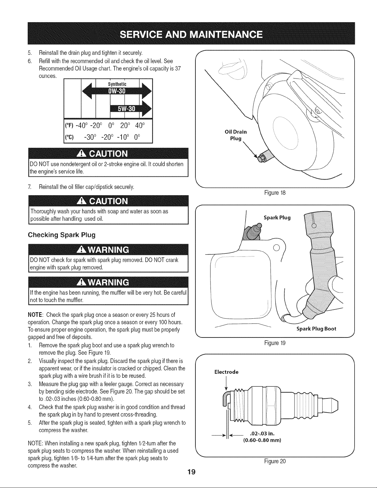
2. Placesuitableoil collectioncontainerunderoildrainplug.
3. Removeoil drainplug.SeeFigure18on nextpage.
4. Tipengineto drainoil intothe container.Usedoilmustbe
disposedofat a propercollectioncenter.
Usedoil isa hazardouswasteproduct.Disposeofusedoil properly.
IDo notdiscardwithhouseholdwaste.Checkwithyour localauthori-
lties or SearsServiceCenterforsafedisposal/recyclingfacilities.
18
Page 19
.
Reinstallthedrainplugandtightenit securely.
6.
Refillwiththerecommendedoil andcheckthe oil level.See
RecommendedOil Usagechart.Theengine'soilcapacityis37
ounces.
i u
[
(%-40 °-20 o 0o 200 400
("c) -300 -200 -10° 0°
DONOTuse nondetergentoilor 2-strokeengineoil.Itcouldshorten
theengine'sservicelife.
Oil Drain
Plug
7. Reinstalltheoilfillercap/dipsticksecurely.
Thoroughlywashyourhandswithsoapandwaterassoonas
possibleafterhandling usedoil.
Checking Spark Plug
DONOTcheckforsparkwithsparkplugremoved.DONOTcrank
enginewithsparkplug removed.
Iftheenginehas beenrunning,themufflerwillbevery hot.Becareful
notto touchthemuffler.
NOTE: Checkthesparkplugoncea seasonorevery25hoursof
operation.Changethesparkplugoncea seasonor every100hours.
Toensureproperengineoperation,thesparkplugmustbeproperly
gappedandfreeof deposits.
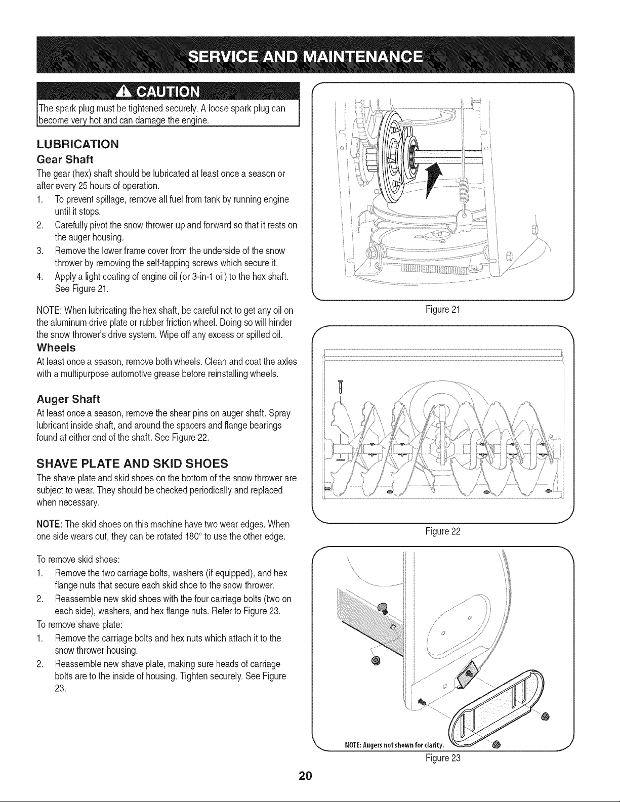
1. Removethesparkplugbootandusea sparkplugwrenchto
removetheplug.See Figure19.
2. Visuallyinspectthesparkplug.Discardthesparkplugif thereis
apparentwear,orif the insulatoriscrackedorchipped.Cleanthe
sparkplugwitha wirebrush ifit isto be reused.
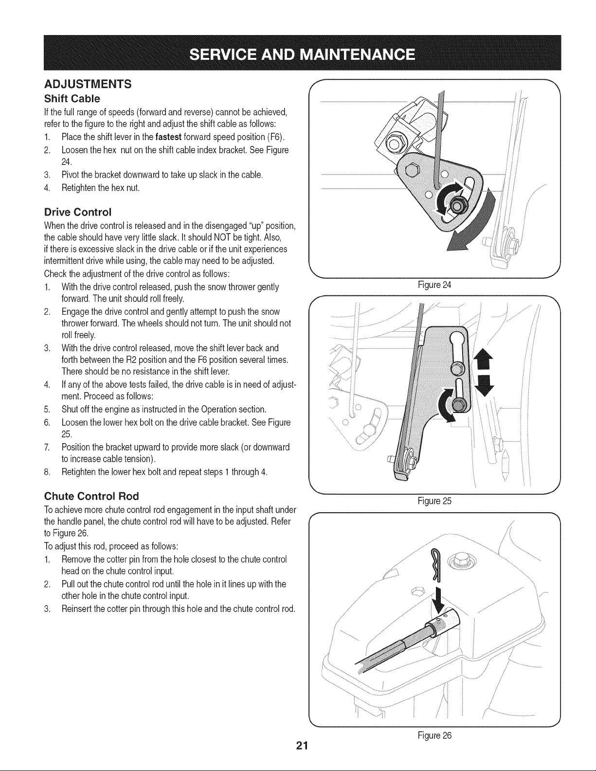
3. Measurethepluggapwitha feelergauge.Correctas necessary
bybendingsideelectrode.SeeFigure20.Thegapshouldbeset
to.02-.03inches(0.60-0.80ram).
4. Checkthatthe sparkplugwasheris ingoodconditionandthread
thesparkplugin by handtopreventcross-threading.
5. Afterthesparkplugis seated,tightenwitha sparkplugwrenchto
compressthewasher.
NOTE:Wheninstallinga newsparkplug,tighten1/2-turnafterthe
sparkplugseatsto compressthewasher.Whenreinstallinga used
sparkplug,tighten1/8-to 1/4-turnafterthe sparkplugseatsto
compressthewasher.
Figure18
Spark Plug
O
J
Figure19
Electrode
.02-.03 in.
{0.60-0.80 ram)
Figure20
19
Page 20
hotandcan ine.
LUBRICATION
Gear Shaft
Thegear(hex)shaftshouldbe lubricatedatleastonceaseasonor
afterevery25 hoursofoperation.
1. Topreventspillage,removeallfuel fromtank byrunningengine
untilit stops.
2. Carefullypivotthesnowthrowerupandforwardsothat it restson
theaugerhousing.
3. Removethe lowerframecoverfromthe undersideofthesnow
throwerbyremovingthe self-tappingscrewswhichsecureit.
4. Applya lightcoatingof engineoil (or3-in-1oil) tothe hexshaft.
SeeFigure21.
NOTE:Whenlubricatingthehexshaft,be carefulnotto getanyoilon
thealuminumdriveplateor rubberfrictionwheel.Doingsowillhinder
thesnowthrower'sdrivesystem.Wipeoff anyexcessorspilledoil.
Wheels
Atleastoncea season,removebothwheels.Cleanandcoattheaxles
witha multipurposeautomotivegreasebeforereinstallingwheels.
Auger Shaft
Atleastoncea season,removethe shearpinson augershaft.Spray
lubricantinsideshaft,andaroundthe spacersandflangebearings
foundat eitherendof theshaft.SeeFigure22.
O i
)
J' "?X
/ .... )
{;:7,_"
7/'................
Figure21
f
SHAVE PLATE AND SKID SHOES
Theshaveplateand skidshoesonthebottomofthesnowthrowerare
subjecttowear.Theyshouldbecheckedperiodicallyandreplaced
whennecessary.
NOTE:Theskidshoeson thismachinehavetwowearedges.When
onesidewearsout,theycan be rotated1800to usetheotheredge.
Toremoveskidshoes:
1. Removethetwocarriagebolts,washers(ifequipped),andhex
flangenutsthat secureeachskidshoeto thesnowthrower.
2. Reassemblenewskidshoeswiththefourcarriagebolts(twoon
eachside),washers,andhex flangenuts.RefertoFigure23.
Toremoveshaveplate:
1. Removethecarriageboltsand hexnutswhichattachit to the
snowthrowerhousing.
2. Reassemblenewshaveplate,makingsureheadsof carriage
boltsaretothe insideof housing.Tightensecurely.SeeFigure
23.
2O
f
\
\
\
NOTE:Augersnotshown for clarity.
J
Figure22
Figure23
Page 21
ADJUSTMENTS
Shift Cable
If thefull rangeofspeeds(forwardandreverse)cannotbeachieved,
referto thefiguretothe rightandadjustthe shiftcableasfollows:
1. Placetheshiftleverin thefastest forwardspeedposition(F6).
2. Loosenthehex nutontheshiftcableindexbracket.SeeFigure
24.
3. Pivotthebracketdownwardtotakeupslack inthecable.
4. Retightenthehexnut.
Drive Control
Whenthedrivecontrolis releasedandin thedisengaged"up"position,
thecableshouldhaveverylittle slack.It shouldNOTbetight. Also,
ifthereisexcessiveslackin thedrivecableor ifthe unitexperiences
intermittentdrivewhileusing,the cablemayneedto beadjusted.
Checktheadjustmentofthe drivecontrolas follows:
1. Withthedrivecontrolreleased,pushthesnowthrowergently
forward.Theunitshouldrollfreely.
2. Engagethedrivecontrolandgentlyattempttopushthesnow
throwerforward.Thewheelsshouldnotturn.Theunitshouldnot
rollfreely.
3. Withthedrivecontrolreleased,movetheshift leverbackand
forthbetweenthe R2positionandtheF6 positionseveraltimes.
Thereshouldbeno resistancein theshiftlever.
4. If anyoftheabovetestsfailed,thedrivecableis in needofadjust-
ment.Proceedasfollows:
5. Shutoff theengineas instructedintheOperationsection.
6. Loosenthelowerhexboltonthe drivecable bracket.SeeFigure
25.
7. Positionthebracketupwardtoprovidemoreslack(or downward
toincreasecabletension).
8. Retightenthelowerhex boltand repeatsteps1 through4.
J
f
.........
Chute Control Rod
Toachievemorechutecontrolrodengagementintheinputshaftunder
thehandlepanel,thechutecontrolrodwill haveto beadjusted.Refer
toFigure26.
Toadjustthis rod,proceedasfollows:
1. Removethecotterpinfromtheholeclosesttothechutecontrol
headon thechutecontrolinput.
2. Pulloutthe chutecontrolroduntilthe holein it linesupwiththe
otherholeinthe chutecontrolinput.
3. Reinsertthecotterpinthroughthis holeandthechutecontrolrod.
21
Figure25
/
/ ,
Figure26
J
J
\
\
Page 22
Auger Control f "_
Refertothe Assemblysectionfor instructionsonadjustingtheauger
controlcable.
/
/
/
/
/
/
Skid Shoes
Refertothe Assemblysectionfor instructionsonadjustingthe skid
shoes.
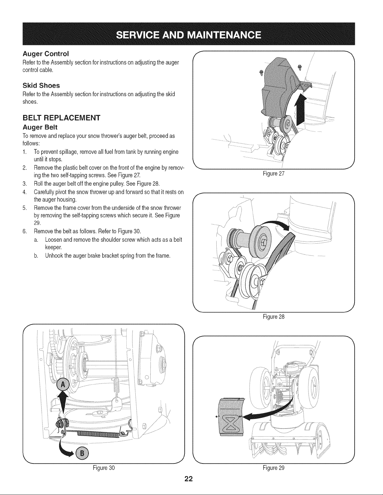
BELT REPLACEMENT
Auger Belt
Toremoveandreplaceyoursnowthrower'saugerbelt,proceedas
follows:
1. Topreventspillage,removeallfuel fromtank byrunningengine
untilitstops.
2. Removethe plasticbeltcoveronthefrontof theengineby remov-
ingthetwoself-tappingscrews.SeeFigure27.
3. Rolltheaugerbeltoff theenginepulley.See Figure28.
4. Carefullypivotthesnowthrowerupandforwardsothat itrestson
theaugerhousing.
5. Removetheframecoverfromtheundersideofthe snowthrower
byremovingtheself-tappingscrewswhichsecureit.SeeFigure
29.
6. Removethe beltas follows.RefertoFigure30.
a. Loosenandremovetheshoulderscrewwhichactsas a belt
keeper.
b. Unhooktheaugerbrakebracketspringfromtheframe.
Figure27
f
J
Figure28
f
i I
Figure30 Figure29
J
J
Page 23
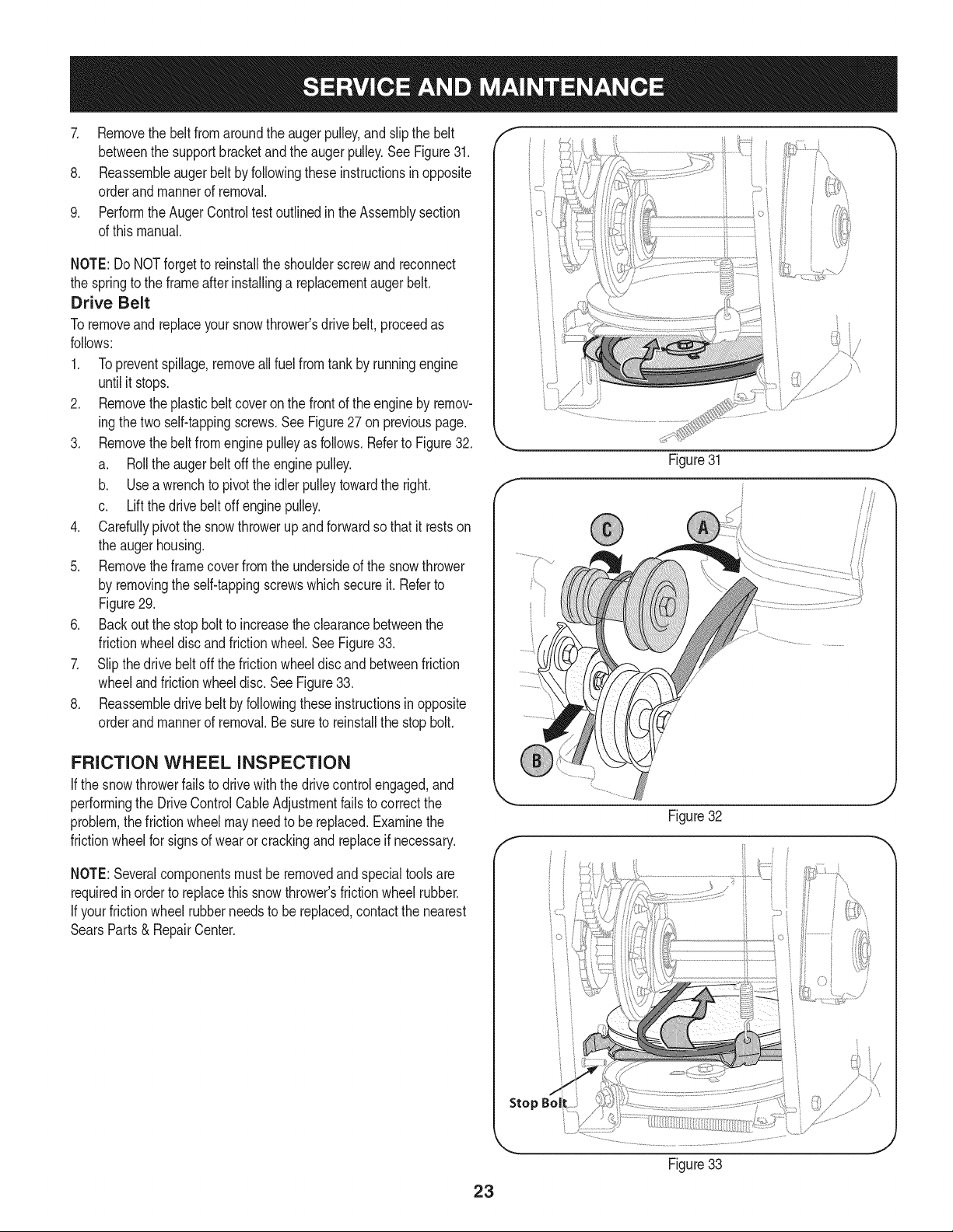
7. Removethebeltfromaroundtheaugerpulley,andslipthebelt
betweenthesupportbracketandtheaugerpulley.SeeFigure31.
8. Reassembleaugerbeltbyfollowingtheseinstructionsinopposite
orderandmannerofremoval.
9. PerformtheAugerControltestoutlinedintheAssemblysection
ofthismanual.
NOTE:DoNOTforgettoreinstalltheshoulderscrewandreconnect
thespringtotheframeafterinstallingareplacementaugerbelt.
Drive Belt
Toremoveandreplaceyoursnowthrower'sdrivebelt,proceedas
follows:
1. Topreventspillage,removeallfuelfromtankby runningengine
untilit stops.
2. Removetheplasticbelt coveronthefrontof theengineby remov-
ingthetwoself-tappingscrews.SeeFigure27onpreviouspage.
3. Removethebeltfromenginepulleyasfollows.Referto Figure32.
a. Rolltheaugerbeltoff theenginepulley.
b. Useawrenchto pivotthe idlerpulleytowardthe right.
c. Liftthedrivebeltoffenginepulley.
4. Carefullypivotthesnowthrowerupand forwardsothat itrestson
theaugerhousing.
5. Removetheframecoverfromtheundersideofthe snowthrower
byremovingtheself-tappingscrewswhichsecureit.Referto
Figure29.
6. Backoutthe stopboltto increasetheclearancebetweenthe
frictionwheeldiscandfrictionwheel.SeeFigure33.
7. Slipthedrivebeltoffthefrictionwheeldiscandbetweenfriction
wheelandfrictionwheeldisc.SeeFigure33.
8. Reassembledrive beltby followingtheseinstructionsinopposite
orderand mannerofremoval.Besureto reinstallthestopbolt.
iO i
Figure31
FRICTION WHEEL INSPECTION
If thesnowthrowerfailsto drivewiththedrivecontrolengaged,and
performingtheDriveControlCableAdjustmentfailstocorrectthe
problem,thefrictionwheelmayneedto be replaced.Examinethe
frictionwheelforsignsof wearor crackingandreplaceifnecessary.
NOTE:Severalcomponentsmustbe removedandspecialtoolsare
requiredinordertoreplacethis snowthrower'sfrictionwheelrubber.
If yourfrictionwheelrubberneedstobereplaced,contactthenearest
SearsParts& RepairCenter.
J
Figure32
f
Stop Bol
Figure33
23
Page 24

Ifthe snowthrowerwillnotbe usedfor30 daysor longer,or ifit istheendofthesnowseasonwhenthelastpossibilityof snowisgone,the
equipmentneedsto bestoredproperly.Followstorageinstructionsbelowtoensuretopperformancefromthesnowthrowerformanymoreyears.
PREPARING ENGINE
Enginesstoredover30daysneedtobedrainedoffueltoprevent
deteriorationandgumfromforminginfuel systemoronessential
carburetorparts.If thegasolineinyourenginedeterioratesduring
storage,youmayneedto havethecarburetor,andotherfuelsystem
components,servicedor replaced.
1. Removeallfuel fromtank byrunningengineuntilitstops.Donot
attempttopourfuel fromtheengine.
2. Changetheengineoil.
3. Removesparkplugandpourapproximately1oz.(30 rnl)of clean
engineoil intothe cylinder.Pullthe recoilstarterseveraltimesto
distributetheoil,and reinstallthesparkplug.
4. Cleandebrisfromaroundengine,andunder,around,andbehind
muffler.Applya lightfilmof oilon anyareasthatare susceptible
torust.
• Storeina clean,dry andwellventilatedareaawayfromanyap-
pliancethatoperateswithaflameor pilotlight,suchasa furnace,
waterheater,or clothesdryer.Avoidanyareawitha spark
producingelectricmotor,orwherepowertoolsareoperated.
Neverstoresnowthrowerwithfuelintank indoorsor inpoorlyventi-
latedareas,wherefuelfumesmayreachanopenflame,sparkorpilol
lightas ona furnace,waterheater,clothesdryerorgas appliance.
PREPARING SNOW THROWER
Whenstoringthe snowthrowerin anunventilatedormetalstor-
age shed,careshouldbetakentorustprooftheequipment.Using
a lightoilor silicone,coattheequipment,especiallyanychains,
springs,bearingsandcables.
• Removealldirt fromexteriorofengineandequipment.
• Followlubricationrecommendations.
• Storeequipmentin a clean,dryarea.
• If possible,avoidstorageareaswithhighhumidity.
• Keepthe enginelevelin storage.Tiltingcancausefuel oroil
leakage.
24
Page 25

Enginefailstostart
Enginerunningerratically/
inconsistentRPM(huntingor
surging)
Excessivevibration
Lossofpower
Unitfailstopropelitself
Unitfailstodischargesnow
1. ChokecontrolnotinCHOKEposition.
2. Sparkplugwire disconnected.
3. Faultysparkplug.
4. Fueltankemptyor stalefuel.
5. Enginenotprimed.
6. Keynot inserted.
7. Extensioncordnotconnected(when
usingelectricstartbutton,on modelsso
equipped).
1. EnginerunningonCHOKE.
2. Stalefuel.
3. Waterordirt infuelsystem.
4. Over-governedengine.
1. Loosepartsor damagedauger.
1. Sparkplugwire loose.
2. Gascap ventholeplugged.
1. Drivecableinneedof adjustment.
2. Drivebeltlooseor damaged.
3. Wornfrictionwheel.
1. Chuteassemblyclogged.
2. Foreignobjectlodgedin auger.
3. Augercablein needof adjustment.
4. Augerbeltlooseordamaged.
5. Shearpin(s)sheared.
1. Movechokecontrolto CHOKEposition.
2. Connectwireto sparkplug.
3. Clean,adjustgap,or replace.
4. Filltankwith clean,freshgasoline.
5. PrimeengineasinstructedintheOperationSection.
6. Insertkeyfully intothe switch.
7. Connectoneendof theextensioncordto theelectric
starteroutletandthe otherendto a three-prong
120-volt,grounded,ACoutlet.
1. Movechokecontrolto RUNposition.
2. Filltankwith clean,freshgasoline.
3. Drainfueltankby runningengineuntilitstops.Refill
withfreshfuel.
4. ContactyourSearsParts& RepairCenter.
1. Stopengineimmediatelyand disconnectsparkplug
wire.Tightenall boltsand nuts.Ifvibrationcontinues,
haveunit servicedbya SearsParts&RepairCenter.
1. Connectandtightensparkplugwire.
2. Removeiceand snowfromgascap. Becertainvent
holeisclear.
1. Adjustdrivecontrolcable.Referto Serviceand
Maintenancesection.
2. Replacedrivebelt.Referto Serviceand Mainte-
nancesection.
3. Changefrictionwheelorcontactyour SearsParts&
RepairCenter.
1. Stopengineimmediatelyand disconnectsparkplug
wire.Cleanchuteassemblyandinsideofauger
housingwithclean-outtoolor a stick.
2. Stopengineimmediatelyand disconnectsparkplug
wire.Removeobjectfromaugerwith clean-outtool
ora stick.
3. Adjustaugercontrolcable.RefertoAssembly
section.
4. Replaceaugerbelt.RefertoServiceand Mainte-
nancesection.
5. Replacewith newshearpin(s).
Chutefailstoeasilyrotate180 1. Disassemblechutecontrolandreassembleas
1. Chuteassembledincorrectly.
degrees directedintheAssemblysection.
NEED HORE HELP?
Yot,Fttfind. th_ answer a!ld mo_e on ma_age_y_ifeocom _ for free]
Find this and att your other product manua[s ontine.
Get answers from our team of home experts.
Get a personalized maintenance p[an for your home.
Find information and tools to he[p with home projects.
managemylife
b_e'_g_t_/_eyeu by Sea_s
25
Page 26

Craftsman Snow Thrower IViodel 247.888301
i27j
@
26
/
/
/
!
/
Page 27

Craftsman Snow Thrower IViodel 247.888301
D = 0 0
731-2635 SnowRemovalToolMount
2. 684-04057A-0637 ImpellerAssembly,12"Dia.
3. L710-0347 LHexScrew,3/8-16,1.75,Gr5
4. 710-0451 Bolt,Carriage,5/16-18,.750Grl
5. 710-04484 Screw,5/16-18,0.750
6. 710-0703 Screw,Carriage,1/4-20,.750,Gr5
7. 712-04063 Nut,FlangeLock,5/16-18,Nylon
8. 712-04064 Nut,FlangeLock,1/4-20,Nylon
9. 712-04065 Nut,FlangeLock,3/8-16,Nylon
10. 714-04040 CotterPin,Bow-tie
11. J725-0157 l Cable,Tie,3/16x .05x 7.4
12. 926-04012 Nut,Push-on,.25Dia
13. 731-07525 Chute,Adapter5"Dia
14. 732-04460 Spring,Extension,.38ODx4.59
15. 736-0174 Washer,Wave,.625x .885x .015
16. 736-0242 Washer,Bell, .340x .872x .060
17. 746-04230A ClutchCable,Auger,47.23"
18. 931-2643 SnowRemovalTool
19. .738-0143 _ Screw,Shoulder,.498x .34,3/8-16
20. 938-0281 Screw,Shoulder,.625x .17,3/8-16
21. 738-04124A ShearPin,.25x 1.50
22. 941-0245 Bearing,HexFlangex .75ID
23. 941-0309 Bearing,Ball,.75IDx 1.85OD
24. 756-04224 FlatPulley,Idler,2.75OD
25. 790-00075 Housing,Bearing,1.85ID
26. 790-00080A-0637 Bracket,AugerIdlerw/Brake
27. J 918-04165A J GearboxAssembly,Auger,30"
28. 684-04267-0691 HousingAssembly,Auger30"
D = O O
684-04107-4028
30. 684-04108-4028
31. 731-04870
32. 736-0188
33. 741-0493A
34. 790-00087A-0637
35. 790-00119-0691
36. 790-00091-0637
37. 918-0123A
38. 918-0124A
39. 921-0338
40. 741-0662
41. 710-0642
42. 711-04282
SpiralAssembly,LH
SpiralAssembly,RH
Spacer,1.25ODx .75IDx 1.00
Washer,Flat,.76x 1.49x .06
Bushing,Flange,.80ID x .91OD
Housing,1"HexBearing
ShavePlate,2.25x29.66
SlideShoe
Housing,Auger,RH Reduced
Housing,Auger,LHReduced
Seal,Oil, .750x 1.00x .125
Bearing,Flange,.75x 1.0x.59
Screw,Self-tapping,1/4-20,0.750
Axle,Auger,30"
43. 914-0161 Key,Hi-pro3/16x 5/8
44. 715-04021 Pin,Dowel,.25ODx 1.2
45. 917-04126 Shaft,Worm.75OD
46. 917-0528A Gear,Worm20T
47. 718-04071 Collar,Thrust
48. 721-0325 Plug,1/4x .437
49. 721-0327 Seal,Oil, .75x 1x .131
50. 936-0351 Washer,Flat,.760IDx 1.50D
51. 736-3084 Washer,Flat,.51x 1.12
52. 741-0663 Bearing,Flange,.75x 1.0x.925
53. 741-0661A Bearing,Flange,.75x 1.00x .975
54. 929-0071A ExtensionCord,110V
55. 790-00181-0637 DriftCutter
56. 731-04871 Spacer,1.25ODx .75IDx3/16
27
Page 28

Craftsman Snow Thrower Model 247.888301
,,65/,
€
28
Page 29

D _ W
684-04112B HandleEngagementAssemblyRH
2. 738-04367 FlangeShoulderScrew
3. 731-04894D LockPlate
4. 684-04250 PivotRod
5. 935-0199A RubberBumper
6. 710-3069 Screw,1/4-20x .500
7. 731-04896B ClutchLockCam
8. 712-04081A ShoulderNut,1/4-20
9. 710-0627 HexScrew,5/16-24x .750
10. 731-06440A LowerChute
11. 725-05149 HeatedGrip
12. 710-1233 Screw,#10-24x0.375
13. 738-04348 ShoulderScrew,1/4-20
14. 710-04586 Screw,1/4-20x 1.625
15. 749-04190A-0691 UpperHandleRH
16. 710-0572 CarriageScrew,5/16-18x2.25
17. 720-04039 ShiftKnob
18. 931-04187A HandlePanel
19. 731-05324 Lens
20. 710-04071 CarriageBolt,5/16-18x 1.0
21. 631-04134B HandleClutchLockAssembly- RH
22. 725-0157 CableTie
23. 712-04064 FlangeLockNut, 1/4-20
24. 732-0193 CompressionSpring
25. 790-00311A-0637 ShiftLever
26. 790-00248C-0637 PanelBracket
27. 738-04125 ShoulderScrew
28. 684-04310A-0637 ChuteSupportBracket
29. 946-04396A SpeedSelectorCable
30. 736-04446 FiatWasher,.25x .630x .0515
31. 710-0895 Hi-LoScrew,1/4-15x .75
32. 710-04370 HexScrew,1/4-20x3.00
33. 731-04427A UpperChute
34. 918-04801A 4-WayChuteGearboxAssembly
35. 710-04187 Hi-LoScrew,1/4-15x 0.5
36. 984-04338 4-WayChuteControlTM Assembly
37. 749-04191A-0691 UpperHandleLH
38. 710-04326 Screw,#8-16x 0.50
39. 732-04219C ClutchLockSpring
40. 712-3087 WingNut,1/4-20
41. 714-04040 BowTieCotterPin
42. 710-0262 CarriageBolt,5/16-18x 1.50
D _ O O
631-04133A HandleClutchLockAssembly- LH
44. 684-04111B HandleEngagementAssemblyLH
45. 784-5594-0637 CableBracket
46. 720-0284 WingKnob
47. 712-04063 FlangeLockNut,5/16-18
48. 731-06451 ChuteTiltCableGuide
49. 711-04469A ClevisPin
50. 710-04484 Screw,5/16-18x0.75
51. 749-04138A-0691 LowerHandle
52. 732-04238 TorsionSpring
53. 936-0267 FiatWasher
54. 710-04022 Screw,M8-1.25
55. 936-0264 FiatWasher,.330x .630x .0635
56. 914-0101 CotterPin
57. 936-0159 FiatWasher,.349x .879x.063
58. 731-06113 SteeringControl
59. 738-04126 Pin,3/16
60. 716-04036 E-Ring
61. 914-0145 ClickPin
62. 732-04677 CableGuide
63. 747-05116 ChuteRod
64. 725-05326 Lamp
65. 725-04393 Switch,HeatedGrip
66. 925-1649 LightSocket
67. 710-0837 Screw,#10-16x .625
68. 753-06151 HandleAssembly
69. 710-0599 Screw(Forgroundwire)
70. 746-04528A 4-WayCable
746-04477 4-WayCablew/Clip(NotShown)
71. 731-04893A HandlePlunger
72. 710-04879 Screw,Mach.,#8-32x .750
73. 710-04353 Screw,#8 x 1.00
74. 731-07031 HandleLever
75. 984-04324A ShiftAssembly
76. 753-06152 GearSetAssembly
77. 753-06153 HandleHousingAssembly
78. 710-1256 Screw,#8-18x 1.250
79. 684-04350 JointBlockAssembly
80. 715-04095 Pin
81. 715-0150 RollPin
-- 725-05148 WireHarn.,HeatedGrip(NotShown)
29
Page 30

Craftsman Snow Thrower IViodel 247.888301 _.._,=_. _ -'-_,
__ 4_ ._
/49__" _ _53)
¢_
_ (761
)
(t
3O
Page 31

D_i BO¸
710-1652 ABScrew,1/4-20x0.625
2. 731-06401 BeltCover
3. 735-04099 Plug,3/8 ID
4. 711-1268B ActuatorShaft
5. 746-04229B DriveClutchCable
6. 732-04345 ExtensionSpring
7. 790-00207B DriveClutchCableGuideBracket
8. 684-04156A ShiftRodAssembly
9. 750-04474 AxleSupportTube
10. 914-0126 HiProKey
11. 735-04100 Plug,1/2 ID
12. 917-04210 Gear,56T
13. 941-0245 HexFlangeBearing
14. 790-00206A-0637 AugerClutchCableGuideBracket
15. 756-0625 CableRoller
16. 738-0924A CScrew,1/4-28x0.375
17. 618-04288 DoggAssembly-LH
618-04287 DoggAssembly-RH
18. 926-04012 Push-onNut
19. 750-04477A Spacer
20. 936-3015 Washer,Fiat
21. 732-04311A TorsionSpring,.7501Dx .968 Lg.
22. 731-05297 Spacer
23. 916-0104 E Ring
24. 736-0188 FiatWasher,.76x 1.49x .06
25. 736-0626 FiatWasher
26. 741-04076 BallBearing
27. 938-04180 Axle
28. L731-04873 Spacer
29. 710-0654A
30. 710-0788
31. 790-00185-0691
32. 634-04136-0911
634-04137-0911
33. 736-0242
34. 710-0627
35. 684-04154B-0637
36. 790-00096-0637
3_ 748-0190
38. 738-04184A
39. 790-00316-0637
40. 656-04055
41. 918-04322A
TTSeresScrew,3/8-16x 1.0
TTScrew,1/4-20x 1.0
ShaftRetainer-LH
WheelComplete-LH
WheelComplete-RH
BellWasher
HexBolt,5/16-24x 0.75
FrictionWheelSupportBrkt.Assy.
AugerCableGuideBracket
Spacer
ShoulderScrew
FrameCover
FrictionWheelDiscAssembly
DriveShaftAssembly
m _ O
684-04159 FrictionWheelAssembly
43. 716-0136 RetainerRing
44. 726-0221 SpeedNut
45. 790-00183B-0637 WheelDriveFrame
46. 756-04109 AugerPulley
47. 736-0505 FiatWasher
48. 738-04439 ShoulderScrew
49. 936-0119 LockWasher
50. 684-04169 IdlerPulleyAssembly
51. 790-00332-0637 Pit.,Cvr.
52. 750-04571 Spacer
53. 732-04308B TorsionSpring
54. 710-0672 HexScrew,5/16-24x 1.25
55. 756-04252 PulleyHalf
56. 954-04201A Belt,WheelDrive
57. 710-0809 TT Screw,1/4-20x 1.25
58. 790-00208C DriveClutchIdlerBracket
59. 748-04112B ShoulderSpacer
60. 932-0264 ExtensionSpring
61. 712-0417A FlangeNut,5/8-18
62. 750-04303 Spacer
63. 756-04113 PulleyHalf
64. 736-0247 FiatWasher
65. 710-0191 HexBolt,3/8-24x 1.25
66. 748-04053A PulleyAdapter
67. 946-0956B SteeringCable
68. 790-00186-0691 ShaftRetainer- RH
69. 750-0767 AxleSpacer
70. 712-04065 FlangeLockNut,3/8-16
71. 954-04195 V-Belt,.500x37.00Lg
72. 710-0751 HexScrew,1/4-20x .620
73. 790-00217A-0637 SpeedSelectorPivotBracket
74. 790-00218A-0637 SpeedSelectorShiftBracket
75. 712-04063 FlangeLockNut,5/16-18
76. 712-04064 FlangeLockNut,1/4-20
77. 618-0063A FrictionWheelBearingAssembly
78. 935-04054 FrictionWheel
79. 790-00174 FrictionPlate
80. 710-0599 Screw,1/4-20x .500
81. 936-0329 LockWasher
82. 736-0320 Washer,Fiat,.38x 1.38x .125
83. 710-1245B HexBolt,5/16-24x0.875
84. 752Z483-SUA ReplacementEngine
31
Page 32

Craftsman Engine Model 483=SUA For Snow Model 247.888301
7
m
1
2
3
4
5
6
7
9
10
11
12
13
14
15
710-04968
951-11339
710-04915
951-10757
951-11595
951-10637
731-05632
951-11302
710-04914
951-11181
951-11321
710-04968
951-11338
712-04219
D = O
Bolt,M6x14
MufflerShield
BoltM6x12
ThrottleControlKnob
ControlPanel
KeySwitch Base
Key
ChokeKnob
BoltM6xlO
ExhaustPipeShield
CarbIsolatorBracket
BoltM6x16
MufflerAssembly
NutM8
32
Page 33

Craftsman Engine IViodel 483-SUA For Snow IViodel 247.888301
_131
rs
c _jj-u
w
,39-
140-0 0114O
141/
m
129
130
131
132
133
134
135
136
138
139
140
141
a
b
¢
d
e
f
g
h
710-05392
710-05056
951-11315
951-11316
951-11223
951-11303A
951-10639A
951-11824
951-11304
951-11192
736-04477
712-04212
n/a
n/a
n/a
n/a
n/a
n/a
n/a
n/a
D = e
StudM6-8x100 Carburetor
StudM6-8x118 Carburetor
CarburetorInsulatorGasket
CarburetorInsulator
CarburetorGasket
CarburetorAssembly
PrimerAssembly
Primer
HeaterBox
ChokeControl
LockWasher
NutM6
ChokeShaft
LockWasher
ScrewM3x5
ChokePlate
ThrottleShaft
ThrottlePlate
LockPlate
IdleJetAssembly
m
J
0
q
t
V
W
X
Y
I
k
I
m
n
P
r
s
U
n/a
n/a
751-11991
951-11906
n/a
n/a
n/a
n/a
n/a
n/a
n/a
951-11970
n/a
951-11348
710-04945
951-11349
710-04938
951-11332A
D = O 0
IdleSpeedAdjustingScrew
MixtureScrew
PrimerHose
HoseClamp
CarburetorBody
FloatPin
EmulsionTube
NeedleValve
MainJet
NeedleValveSpring
Float
FuelBowlGasket
FuelBowl
FuelBowlGasket
FuelBowlMountingBolt
FuelDrainPlugGasket
FuelDrainPlug
CarburetorKit- Major
(Incl.g,h,n,o,p,q,r,w,t,v,x)
33
Page 34

Craftsman Engine IViodel 483=SUA For Snow IViodel 247.888301
142
41
I
44 43
34
Page 35

Craftsman Engine IViodel 483=SUA For Snow IViodel 247.888301
m
41
42
43
44
45
49
5O
51
52
53
54
55
56
57
58
59
60
61
62
63
64
65
66
67
68
951-11951
951-11952
951-11953
951-11954
951-12579
951-11956
951-11373
736-04453
714-04077
951-11958
951-11365
951-11342
951-10307
715-04102
715-04092
951-11959
951-11376
736-04476
951-11960
951-11345
951-11340
951-11375
710-04971
710-04972
710-05052
m = O Q
ConnectingRodAssembly
Piston
PistonPinSnapRing
PistonPin
PistonRingSet
GovernorGear/ShaftAssembly
RadialBallBearing6202-P6
Washer8x20x0.8
CotterPin
GovernorSeal
GovernorArm Shaft
CrankshaftKit
(Incl.50,55,56,65,81)
WoodruffKey
DowelPin9x12
DowelPin7x14
CamshaftAssy.
CrankcaseCoverGasket
Washer16x24x0.5
O-Ring16x3
Oil FillerPlugAssembly
CrankcaseCoverKit
(Incl.50,60,61,64-68)
Oil Seal30x46x8
BoltM8x38
BoltM8x45
BoltM8x35
m
69
7O
71
73
74
75
76
77
78
79
8O
81
142
143
150
710-04968
951-11320
710-05349
951-11381
951-11972
951-11904
951-11971A
951-11341A
951-11350
736-04440
710-04906
951-11499
951-11968
951-11969
951-10641
952Z483-SUA
951-11331
951-11330A
951-11328B
m = W O
BoltM6x16
DipstickClamp
BoltM6x8
Oil FillTubeO-Ring
Oil FillTubeAssembly
DipstickO-Ring
DipstickAssembly
CrankcaseKit
(In01.50,53,77,81)
Oil DrainPipeAssy.
Washer10x16x1.5
Oil DrainPlug
OilSeal35x52x7
BalanceableShaftAssy.
Bearing6207-P6
Oil DrainAssembly
CompleteEngine
GasketKit- External
(Incl.79,108,125,131-133)
GasketKit- Complete
(Incl.53,60,65,79,81,106,
108,125,131-133)
ShortBlockAssembly
(Incl.41-45,49-61,63-68,77-79,
81,102,105,106,108,110,125,
131,132,142,143)
35
Page 36

Craftsman Engine Model 483-SUA For Snow Model 247.888301
149
123
107
125
123
_126a
(_ ,126
115
113
115
114
122 121 120 119
113
I
118
110_
11_
112
_I04
103
36
Page 37

Craftsman Engine IViodel 483=SUA For Snow IViodel 247.888301
m
1CO
101
102
103
104
105
106
107
108
109
109
110
111
112
113
114
115
116
117
118
119
951-11337
951-11337
951-11962
951-11335
951-12555
715-04097
951-11963
951-10292
951-11212
710-04964
951-11207
710-05053
710-05390
951-11964
951-12077
951-12078
951-12080
951-12081
951-11965
951-11981
710-04962
D = O
ValveKit
ValveKit
Tappet
PushRod
CylinderHeadKit
(Inc1.106,110-112,125)
DowelPin12x20
GasketCylinderHead
SparkPlug/F6Rtc
ExhaustPipeGasket
StudM8x48.5
MufflerStudAssembly
BoltM10x1.25x87
BoltM10x1.25x65
IntakeValveSeal
ValveSpringRetainer
ValveSpring
RetainerEx.ValveSpring
AdjusterExhValve
PushRodGuide
RockerArmAssembly
BoltPivot
m
120
121
122
123
125
124
126
126a
127
128
149
951-11966
751-11123
751-11124
710-05054
951-11967
951-11220
951-11221
726-04101
951-11317
710-04915
951-11333
952Z483-SUA
951-11331
951-11330A
951-11329B
D = W O
RockerArm
AdjustingNut,Valve
NutPivotLocking
ValveCoverBolt
ValveCoverGasket
ValveCover
BreatherHose
BreatherHoseClamp
Air Shield
BoltM6x12
ValveCoverKit
CompleteEngine
GasketKit- External
(Incl.79,108,125,131-133)
GasketKit- Complete
(Incl.53,60,65,79,81,106,
108,125,131-133)
CylinderHeadAssembly
(Inc1.100,101,104,106,108-110,
112,114-117,119-122,125,
129,130-132)
37
Page 38

Craftsman Engine Model 483=SUA For Snow Model 247.888301
87
84
4
82
85
m
46
47
48
82
83
84
85
86
87
88
710-04965
951-11196
710-04967
951-11305
710-05350
951-11961
710-04969
710-04966
951-11186
951-11312
88
89
m = O
BoltM4x55
StartupElectromotor
BoltM8x55
IgnitionCoilAssembly
IgnitionCoilBolt
CoilAssy.Oharge
BoltM6x30
BoltM6x8
AItWireClampBrkt
Flywheel
m
89
90
91
92
93
95
96
97
98
148
91
951-11313
951-11314
712-04220
710-04968
710-04915
951-11211
951-11310
736-04455
710-04974
731-05696
96
97
D = O
FanCooling
PulleyStarter
NutSpecialM16x1.5
BoltM6x16
BoltM6x12
BlowerHousing
RecoilStarter
Gasket6
BoltM6xlO
StarterHandle
38
Page 39

Craftsman Engine Model 483-SUA For Snow Model 247.888301
18 -19
18
m
16
17
18
19
2O
21
22
23
24
25
26
27
28
40_ 39 26/
36
951-12532
951-11933
710-04970
750-05312
750-05313
951-11201
951-11319
951-11318
951-11351
710-04968
736-04452
951-11336
951-11700
FuelCapAssembly
FuelLevelIndicator
BoltM8x20
BushGasTank
BushGasTank
FuelTankAssembly
LeftTrimPlate
RearMaintingBracketAssy.
RightTrimPlate
BoltM6x16
Bush
FuelHoseKit
FuelHoseClamp
/25
%
D = O
_ 27
26
m
29
30
31
33
34
35
36
37
38
39
40
N/S
710-04921
951-11182
712-04219
712-04212
710-04908
951-11307
951-11306
951-11203
951-11309
951-11311
710-04916
951-10651
BoltM8x14
GasTankSupportBracket
NutM8
NutM6
GovernorArm Bolt
GovernorArm
GovernorSpring
ThrottleLinkageSpring
ThrottleLinkage
PrimerBracket
BoltM6x14
FuelTankNipple
I
D = O O
39
Page 40

Craftsman Engine IViodel 483=SUA For Snow IViodel 247.888301
777123018
777123039
777S33614
777123027
SERIALNUMBER
BAR CODELABEL
777123017
777122992
EPA LABEL
4O
Page 41

Craftsman Snow Thrower IVlodel 247.888301
777S32636
• -- [ -- 3001 lnO'NV:Z30 •
"WflNVW S,UOIVH3dO QV]H '_
N3HMNOIlflPO VHIX3 3Sfl '$810NVISt81P 39UVHOSIO
103U10U3fi3N 'S31HflrNI $10]P80 NMOUH1 OlOAV 01 '_
3H0338 O]dd01S ]AVH SlUVd 9NIAOW TIP 311Nil S33QNVH
]NIH38 NIVW]U QNV '3NION] d01S '8_A33 HOlfl]O 39VgN3SIQ'8
"]INH9 39HVHOSIO 90"lONn 013001 lnO'NP3"lO ]sfl "g
'133_ ONVSONVH]IVIfldWV NVOEI39nv 80 U3113d_l HIIM
lOVINO0 'u39nv ONVE3333dFJI 9NIIVIOU _OUd AVMVd33H "L
'S30V_HflS ]3AVH9 NO9NllPU]dO
'3NIHOVW 9NIOIAU3S HO 9NIOOO30Nfl
777122339
777122363
777S32236
777123013
777D16350
777D16340
777D16348
777122340
777X43688
/ CONTAININGMORE
THAN10% ETHANOL
777D16351
41
Page 42

MTD CONSUMER GROUP INC (MTD), the California Air Resources Board (CARB)
and the United States Environment Protection Agency (U. S. EPA)
Emission Control System Warranty Statement
(Owner's Defect Warranty Rights and Obligations)
EMISSIONCONTROLSYSTEMCOVERAGEISAPPLICABLETOCERTIFIEDENGINESPURCHASEDINCALIFORNIAIN2005ANDTHERE-
AFTER,WHICHAREUSEDINCALIFORNIA,ANDTO CERTIFIEDMODELYEAR2005ANDLATERENGINESWHICHAREPURCHASEDAND
USEDELSEWHEREINTHEUNITEDSTATES.
Californiaandelsewherein theUnitedStatesEmissionControlDefectsWarrantyCoverage
TheCaliforniaAir ResourcesBoard(CARB),U.S.EPAandMTDarepleasedtoexplaintheemissionscontrolsystemwarrantyonyourmodelyear
2006andlatersmalloff-roadengine.InCalifornia,newsmalloff-roadenginesmustbe designed,builtandequippedtomeettheStatesanti-smog
standards.ElsewhereintheUnitedStates,newnon-road,spark-ignitionenginescertifiedfor model2005and later,mustmeetsimilarstandardsset
forthbythe U.S.EPA.MTDmustwarrantytheemissioncontrolsystemonyourenginefortheperiodoftimelistedbelow,providedtherehasbeen
noabuse,neglector impropermaintenanceof yoursmalloff-roadengine.
Youremissioncontrolsystemmayincludepartssuchas thecarburetor,fuel-injectionsystem,theignitionsystem,andcatalyticconverter,fueltanks,
fuellines,fuel caps,valves,canisters,filters,vaporhoses,clamps,connectors,andotherassociatedemission-relatedcomponents.
Whereawarrantableconditionexists,MTDwill repairyoursmalloff-roadengineat nocostto yourincludingdiagnosis,partsandlabor.
MANUFACTURER'S WARRANTY COVERAGE:
Thisemissionscontrolsystemiswarrantedfortwoyears.If anyemission-relatedpart onyourengineisdefective,thepartwill berepairedor
replacedbyMTD.
OWNER'S WARRANTY RESPONSIBILITIES:
Asthe smalloff-roadengineowner,youare responsibleforthe performanceofthe requiredmaintenancelistedinyourOwner'sManual.MTD
recommendsthatyouretainall yourreceiptscoveringmaintenanceson yoursmalloff-roadengine,but MTDcannotdenywarrantysolelyforthe
lackofreceiptsor foryour failureto ensuretheperformanceto allscheduledmaintenance.
Asthe smalloff-roadengineowner,youshouldhoweverbeawarethatMTDmaydenyyourwarrantycoverageifyoursmalloff-roadengineorpart
hasfaileddue toabuse,neglect,impropermaintenanceor unapprovedmodifications.
Youare responsibleforpresentingyour smalloff-roadenginetoan AuthorizedMTDServiceDealerassoonas a problemexists.Thewarranted
repairsshouldbe completedina reasonableamountof time,nottoexceed30 days.
Ifyouhaveanyquestionsregardingyourwarrantyrightsandresponsibilities,youshouldcontacta MTDServiceRepresentativeat 1-800-800-7310
andaddressisMTDCONSUMERGROUP,RO.Box361131,ClevelandOH,44136-0019.
DEFECTS WARRANTY REQUIREMENTS FOR 1995 AND LATER SMALL OFF-ROAD ENGINES:
Thissectionappliesto 1995andlater smalloff-roadengines.Thewarrantyperiodbeginsonthedatetheengineorequipmentisdeliveredtoan
ultimatepurchaser.
(a) GeneralEmissionsWarrantyCoverage
MTDmustwarranttothe ultimatepurchaserandeachsubsequentpurchaserthatthe engineis:
(1)Designed,built,andequippedsoasto conformwithallapplicableregulationsadoptedbytheAirResourcesBoardpursuantto itsauthorityin
Chapters1and2,Part5, Division26of theHealthandSafetyCode;and
(2) Freefromdefectsin materialsandworkmanshipthatcausethefailureofa warrantedparttobeidenticalin all materialrespectstothepartas
describedin theenginemanufacturer'sapplicationforcertificationfora periodoftwoyears.
(b)Thewarrantyonemissions-relatedpartswill be interpretedasfollows:
(1)Anywarrantedpartthatisnot scheduledforreplacementas requiredmaintenanceinthewritteninstructionsrequiredbySubsection(c)
mustbewarrantedforthewarrantyperioddefinedinSubsection(a)(2).Ifanysuchpartfailsduringtheperiodof warrantycoverage,it mustbe
repairedor replacedbyMTDaccordingto Subsection(4)below.Anysuchpartrepairedorreplacedunderthewarrantymustbewarrantedfor
theremainingwarrantyperiod.
(2)Anywarrantedpartthat isscheduledonlyfor regularinspectioninthewritteninstructionsrequiredbySubsection(c) mustbewarrantedfor
thewarrantyperioddefinedinSubsection(a)(2).A statementinsuchwritteninstructionstotheeffectof"repairor replaceasnecessary"will
notreducetheperiodof warrantycoverage.Anysuchpartrepairedorreplacedunderwarrantymustbe warrantedfortheremainingwarranty
period.
(3) Anywarrantedpartthat whichisscheduledfor replacementas requiredmaintenanceinthewritteninstructionsrequiredbySubsection(c)
mustbewarrantedfortheperiodof timepriortothe firstscheduledreplacementpointforthatpart.Ifthepartfailspriorto thefirstscheduled
replacement,thepart mustbe repairedor replacedbyMTDaccordingto Subsection(4) below.Anysuchpart repairedor replacedunder
warrantymustbewarrantedforthe remainderof theperiodpriorto thefirst scheduledreplacementpointforthe part.
Page 43

(4)Repairorreplacementofanywarrantedpartunderthewarrantyprovisionsofthisarticlemustbeperformedatnochargetotheownerata
warrantystation.
(5)NotwithstandingtheprovisionsofSubsection(4)above,warrantyservicesorrepairsmustbeprovidedatallMTDdistributioncentersthat
arefranchisedtoservicethesubjectengines.
(6)Theownermustnotbechargedfordiagnosticlaborthatleadstothedeterminationthatawarrantedpartisinfactdefective,providedthat
suchdiagnosticworkisperformedatawarrantystation.
(7)Theenginemanufacturerisliablefordamagestootherenginecomponentsproximatelycausedbyafailureunderwarrantyofanywarranted
part.
(8)Throughouttheengine'swarrantyperioddefinedinSubsection(a)(2),MTDwillmaintainasupplyofwarrantedpartssufficienttomeetthe
expecteddemandforsuchparts.
(9)Anyreplacementpartmaybeusedintheperformanceofanywarrantymaintenanceorrepairsandmustbeprovidedwithoutchargetothe
owner.SuchusewillnotreducethewarrantyobligationsofMTD.
(10)Add-onormodifiedpartsthatarenotexemptedbytheAirResourcesBoardmaynotbeused.Theuseofanynon-exemptedadd-onor
modifiedpartsshallbegroundsfordisallowingawarrantyclaimmadeinaccordancewiththisarticle.Theenginemanufacturershallnotbe
liableunderthisarticletowarrantfailuresofwarrantedpartscausedbytheuseofnon-exemptedadd-onormodifiedpart.
(c)MTDwillincludea copyofthe followingemissionwarrantypartslistwitheachnewengine,usingthoseportionsofthelistapplicabletothe
e__&gine.
(1)FuelMeteringSystem
•Coldstartenrichmentsystem(softchoke)
,,Carburetorandinternalparts
•FuelPump
•FuelTank
(2)Air InductionSystem
•Aircleaner
•Intakemanifold
(3) IgnitionSystem
•Sparkplug(s)
•MagnetoIgnitionSystem
(4)ExhaustSystem
Catalyticconverter
•SAI(Reedvalve)
(5) MiscellaneousItemsUsedin AboveSystem
Vacuum,temperature,position,timesensitivevalvesandswitches
Connectorsandassemblies
(6) Evaporativecontrol
•FuelHosecertifiedforARBevaporativeemissionof2006.
•FuelHoseClamps
Tetheredfuelcap
Carboncanister
Vaporlines
GD0C-100174Rev.B
Page 44

Look For Relevant Emissions Durability Period and
Air index information On Your Engine Emissions Label
Engines that are certified to meet the California Air Resources Board (CARB) Tier 2 Emission Standards must
display information regarding the Emissions Durability Period and the Air Index. Sears Brands Management
Corporation makes this information available to the consumer on our emission labels.
The Emissions Durability Period describes the number of hours of actual running time for which the engine is
certified to be emissions compliant, assuming proper maintenance in accordance with the Operating & Mainte-
nance Instructions. The following categories are used:
Moderate: Engine is certified to be emission compliant for 125 hours of actual engine running time.
Intermediate: Engine is certified to be emission compliant for 250 hours of actual engine running time.
Extended: Engine is certified to be emission compliant for 500 hours of actual engine running time.
For example, a typical walk-behind lawn mower is used 20 to 25 hours per year. Therefore, the Emissions
Durability Period of an engine with an intermediate rating would equate to 10 to 12 years.
The Air index is a calculated number describing the relative level of emissions for a specific engine family. The
lower the Air Index, the cleaner the engine. This information is displayed in graphical form on the emissions label.
After July 1,2000, Look For Emissions Compliance Period
On Engine Emissions Compliance Label
After July 1, 2000 certain Sears Brands Management Corporation engines will be certified to meet the United
States Environmental Protection Agency (USEPA) Phase 2 emission standards. For Phase 2 certified engines, the
Emissions Compliance Period referred to on the Emissions Compliance label indicates the number of operating
hours for which the engine has been shown to meet Federal emission requirements.
For engines less than 225 cc displacement, Category C = 125 hours, B = 250 hours and A = 500 hours.
For engines of 225 cc or more, Category C = 250 hours, B = 500 hours and A = 1000 hours.
This isa generic representation of the emission label typically found on a certified engine.
FAMILYYBSXS.3192VA 274812
44
GDOC-100182Rev.B
Page 45

Congratulations on making a smart purchase. Your new Craftsman® product is designed and
manufactured for years of dependable operation. But like all products, it may require repair
from time to time. That's when having a Repair Protection Agreement can save you money and
aggravation.
Here's what the Repair Protection Agreement* includes:
[] Expert service by our 10,000 professional repair specialists
[] Unlimited service and no charge for parts and labor on all covered repairs
[] Product replacement up to $1500 if your covered product can't be fixed
[] Discount of 25% from regular price of service and related installed parts not covered by the
agreement; also, 25% off regular price of preventive maintenance check
[] Fast help by phone - we call it Rapid Resolution - phone support from a Sears representative.
Think of us as a "talking owner's manual."
Once you purchase the Repair Protection Agreement, a simple phone call is all that it takes for you
to schedule service. You can call anytime day or night, or schedule a service appointment online.
The Repair Protection Agreement is a risk-free purchase. If you cancel for any reason during the
product warranty period, we will provide a full refund. Or, a prorated refund anytime after the
product warranty period expires. Purchase your Repair Protection Agreement today!
Some limitations and exclusions apply. For prices and additional information in the U.S.A.
call 1=800=827=6655.
*Coverage in Canada varies on some items. For full details call Sears Canada at 1=800=361=
6665.
Sears Installation Service
For Sears professional installation of home appliances, garage door openers, water heaters, and
other major home items, in the U.S.A. or Canada call 1=800=4=MY=HOME®.
45
Page 46

Declaraci6n de garantia ............................ Pagina 46
Practicas operaci6n seguras ..................... Pagina 47
Montaje ...................................................... Pagina 51
Operaci6n .................................................. Pagina 57
Servicio y Mantenimiento .......................... Pagina 62
Soluci6n de problemas .............................. Pagina 70
Acuerdo de protecci6n para reparaciones ....Pagina 75
Lista de piezas ........................................... Pagina 26
NOmero de servicio ................................... Cubierta
posterior
Almacenamiento fuera de temporada ....... Pagina 69
GARANTiA PROFESIONAL TOTAL CRAFTSMAN POR DOS AltOS
PORDOSANOSapartir dela fechade cornpra,esteproductoest&garantizadocontracualquierdefectodematerialornanodeobra.El
productodefectuosorecibir_,la reparaci6no lasustituci6ngratuitasila reparaci6nnoest,.disponible.
Estagaranfias61otienevigenciapot unaSodesdela fechade cornprasiesteproductosehanutilizadoalgunavez,rnientrasquela prestaci6n
de servicioscornercialeso si sealquilaa otrapersona.
Paraobtener informacibndetallada coberturadelagarantiaparaobtener la reparacibno reemplazo,visite el sitio web:
www.craftsman.com
Esta garantiacubre SOLOdefectos en material y habilidad. Lacobertura de garantiano incluye:
• Elernentosreutilizablesquepuedengastarseporel uso normaldentrodel periodode garanfia,incluso,peronolirnitadosparabarrenas,
barrenarernos,cortadoresdernovirniento,patinarzapatos,platodeafeitado,esquilanalfileres,bujia,filtrodeaire,cinturones,yfiltrodel
aceite.
• Revisi6ndernantenirnientoest_.ndar,carnbiosdeaceite,o puestasapunto.
• Reernplazodeneurn_.ticoo reparaci6ncausadaporpinchazosdesdefuerade objetos,cornou_as,espinas,tocones,ocristal.
• Neurn_.ticoo reernplazoderuedao reparaci6nqueresultade ropanormal,accidente,uoperaci6nirnpropiao rnantenirniento.
• Las reparacionesnecesariasdebidoal abusodeoperador,inclusoperonolirnitadoparada_arcausadoafectandoobjetosquedoblanel
marcoo la barrenaeje,o elsobreexcesode velocidaddelmotor.
• Reparacionesnecesariasdebidoanegligenciadeloperador,induyendoentreotros,da_osrnec_.nicoy el_ctricoocasionadoporun
alrnacenarnientonoapropiado,fallapot el usode aceitedegradoy/o cantidadnoapropiadaofallapor nodarrnantenirnientoal equipode
acuerdoconlasinstruccionescontenidasenel manualdeloperador.
• Lirnpiezao reparacionesal motor(sisternadecombustible)provocadasporuncombustiblecontarninadouoxidado(viejo).Engeneral,el
combustibledebeutilizarseenunperiodono mayorde30dias a partirde su adquisici6n.
• Elernpejorarnientonormaly la ropade losfinesexteriores,oproductoetiquetanelreernplazo.
Estagarantialeotorgaderechoslegalesespecificos,peroustedpodriagozardeotrosderechosenraz6nde sulugarderesidencia.
Sears Brands ManagementCorporation, Hoffman Estates,IL 60179
Tipode aceitedelmotor:
Capacidaddeaceitedel motor:
Capacidaddecombustible:
Bujfas:
Separaci6nde lasbujias:
©KCDIP,LLC
SAE 5W-30
37 onzas
Aprox. 5 cuartos
F6RTC
.020" a .030"
N_merode modelo ..........................................................
N_merode sede ..............................................................
Fechade compra .............................................................
RegistrearribaelnOrnerodel rnodelo,elnOrnerode seriey lafecha
decornpra
46
Page 47

Lapresenciadeeste sfrnboloindicaquesetratadeinstrucciones
irnportantesde seguridadquesedebenrespetarparaevitar
ponerenpeligrosuseguridadpersonaly/omaterialylade otras
personas.Leay sigatodaslas instruccionesdeestemanualantes
de poneren funcionarnientoestarn_.quina.Sinorespetaestas
instruccionespodrfaprovocarlesionespersonales.Cuandoveaeste
sfrnbolo,ipresteatenci6nala advertencia!
Estarn_.quinarueconstruidaparaseroperadadeacuerdocon
lasreglasde seguridadcontenidasenestemanual.AIigualque
concualquiertipodeequipornotorizado,undescuidooerrorpor
partedeloperadorpuedeproducirlesionesgraves.Estarn_.quina
escapazde arnputarrnanosy piesy dearrojarobjetoscongran
fuerza.Deno respetarlasinstruccionesde seguridadsiguientesse
puedenproducirlesionesgraveso larnuerte.
PROPOSICION 65 DE CALIFORNIA
Elescapedel motordeesteproducto,algunosdesuscornponentes
y algunoscornponentesdelvehfculocontieneno liberansustancias
qufrnicasqueelestadodeCaliforniaconsideraque puedenproducir
c_.ncer,defectosde nacirnientouotrosproblernasreproductivos.
CAPACITACI6N
• Lea,entiendaycurnplatodaslas instruccionesincluidasen
la rn_.quinayen losrnanualesantesdernontarlay utiNzarla.
Guardeestemanualenun lugarseguroparaconsultasfuturasy
peri6dicas,asf cornoparasolicitarrepuestos.
• Leael ManualdelOperadorysigatodaslasadvertenciase
instruccionesdeseguridad.Elfracasode hacerasfpuedecausar
la heridaseriaal operadory/opersonaspresentes.
• Farniliarfcesecontodosloscontrolesycon el usoadecuado
delosrnisrnos.Sepac6rnodetenerlarn_.quinaydesactivarlos
controlesr_.pidarnente.
• No perrnitanuncaque losni_osrnenoresde14a_osutilicen
estarn_.quina.Los ni_osde 14a_osen adelantedebenleery
entenderlasinstruccionesde operaci6ny norrnasdeseguridad
contenidaseneste manual,yen la rn_.quinaydebenserentrena-
dosy supervisadosporun adulto.
• Nuncaperrnitaquelosadultosoperenestarn_.quinasin recibir
antesla instrucci6napropiada.
• Losobjetosarrojadosporla rn_.quinapuedenproducirlesiones
graves.Planifiqueel patr6nenel queva air arrojandonievepara
evitarque ladescargade materialserealicehacialos carninos,
losobservadores,etc.
• Mantengaalosobservadores,ayudantes,rnascotasy ni_ospor
Iornenosa 75piesde la rn_.quinarnientraslarnisrnaest,.en
funcionarniento.Detengalarn_.quinasialguienseacerca.
• Seaprecavidoparaevitarpatinarseocaerseespecialrnente
cuandooperala rn_.quinaen reversa.
Su responsabilidad--Restrinja el usodeestarn_.quina
rnotorizadaalas personasque lean,cornprendany respetenlas
advertenciase instruccionesqueaparecenen estemanualyen la
rn_.quina.
iGUARDEESTASINSTRUCCIONES!
PR E PARATIVO S
Inspeccionerninuciosarnenteel_.readondeutilizar_,el equipo.Saque
todoslosfelpudos,peri6dicos,trineos,tablas,cablesy otrosobjetos
extra_osconlosquepodrfatropezaro quepodrfanserarrojadospor
labarrena/irnpulsor.
• Paraprotegerselosojos utilicesiernpreanteojosoantiparras
de seguridadrnientrasoperala rn_.quinao rnientrasla ajusta
o repara.Losobjetosarrojadosquerebotanpuedenproducir
lesionesocularesgraves.
• Nooperelarn_.quinasin la vestirnentaadecuadaparaestaral
airelibreen invierno.Noutilicealhajas,bufandaslargasu otras
prendassueltasquepodrfanenredarseenlaspartesrn6viles.
UtiNceun calzadoespecialparasuperficiesresbaladizas.
• Useun prolongadory untornacorrientedetrescablescon
conexi6na tierraparatodaslas rn_.quinascon rnotoresde
encendidoel_ctrico.
• Ajustelaalturade lacajadeltornacorrienteparaNrnpiarla grava
o lassuperficiesconpiedrastrituradas.
• Desengranetodaslaspalancasdecontrolantesde arrancarel
motor.
• Nuncaintenterealizarajustesrnientrasel motorest,.enrnarcha
exceptoenlos casosespecfficarnenterecornendadosen el
manualdeloperador.
• Dejequeelmotory la rn_.quinaseadaptena laternperatura
exteriorantesde cornenzara sacarla nieve.
4.7
Page 48

Manejoseguro de la gasolina
Paraevitarlesionespersonales0 daSosrnaterialestengarnucho
cuidadocuandotrabajecon gasolina.Lagasolinaessurnarnente
inflarnabley susvaporespuedencausarexplosiones.Si sederrarna
gasolinaencirna0 sobrela ropase puedelesionargravernenteyaque
sepuedeincendiar. L&vesela piely c&rnbiesede ropade inrnediato.
• Utilices610los recipientesparagasolinaautorizados.
• Apaguetodoslos cigarrillos,cigarros,pipasy otrasfuentesde
cornbusfi6n.
• Nuncacarguecombustibleen larn&quinaen unespaciocerrado.
• Nuncasaquela tapadelcombustibleniagreguecombustible
rnientrasel motorest&caliente0 en rnarcha.
• Dejequeel motorseenfrieporI0rnenosdosrninutosantesde
volvera cargarcombustible.
• Nuncalleneenexcesoel dep6sitodecombustible.Lleneel
tanqueano rn&sde1/2pulgadapordebajode la basedelcuello
de Ilenadodejandoespacioparaladilataci6ndeIcombustible.
• Vuelvaa colocarla tapade lagasoiinay aj_stelabien.
• Lirnpieelcombustiblequese hayaderrarnadosobreel motoryel
equipo.Trasladela rn&quinaa otra zona.Espere5rninutosantes
deencenderelmotor.
• Nuncaalrnacenela rn&quina0 el recipientedecombustibleen
unespaciocerradodondehayafuego,chispas0luzpiloto(por
ejernplo,hornos,calentadoresdeagua,calefactores,secadores
de ropa,etc.).
• Dejequela rn_.quinaseenfrieporIornenos5 rninutosantesde
guardarla.
• NuncaIlenelosrecipientesenel interiordeunvehiculoo carni6n
ocajade rernolquecon recubrirnientospl_.sticos.Coloque
siernprelosrecipientesenel pisoy lejosdelvehiculoantesde
Ilenarlos.
• Sies posible,retireelequipoagasolinadelcarni6no rernolque
yII_neloenel suelo.Siestonoes posible,Ileneelequipoenun
rernolqueconcontenedorport_.til,envezdedesdeunaboquilla
dispensadoradegasolina.
• Mantengalaboquilladispensadoraen contactoconel hordedel
dep6sitode combustibleo conla aberturadel recipienteentodo
rnornento,hastaterrninarlacarga.No utiliceundispositivode
apertura/cierrede boquilla.
FUNCIONANIIENTO
• No pongalasrnanoso lospiescercadelaspiezasrotatorias,
en lacajade la barrena/ irnpulsoro en el rnontajedelcanalde
descarga.Hacercontactocon piezasgiratoriaspuederesultaren
laarnputaci6ndernanosopies.
• La palancadecontrolde la barrena/ irnpulsoresun dispositivo
de seguridad.Nuncaevitesufuncionarniento.De hacerlola
operaci6nde la rn_.quinaesriesgosay puedeocasionarlesiones.
• Las palancasdecontroldebenfuncionarbienen arnbasdirec-
cionesy regresarautorn_.ticarnentea la posici6ndedesengrane
cuandose lassuelta.
• Nuncaoperela rn_.quinasifaltaunrnontajedelcanalo si el
rnisrnoest,.daSado.Mantengatodoslosdispositivosdeseguri-
daden sulugary enfuncionarniento.
• Nuncaenciendaelmotorenespacioscerradoso en unazona
conpocaventilaci6n.Elescapedel motorcontienernon6xidode
carbono,ungasinodoroy letal.
• Noutilicela rn_.quinabajola influenciadelalcoholo lasdrogas.
• Elsilenciadoryel motorse calientanypuedencausarquernadu-
ras.Nolos toque.Mantengaa losniSosalejados.
• Seasurnarnenteprecavidocuandooperelarn_.quinasobreuna
superficiecongravaocuandola cruce.Mant_ngasealertaporsi
sepresentanpeligrosocultosotr_.nsito.
• Tengacuidadocuandocarnbiededirecci6nocuandoopere
la rn_.quinaenpendientes.Nousela rn_.quinaenpendientes
pronunciadas.
• Planifiqueel patr6nenel quevaair arrojandonieveparaevitar
que ladescargade materialseproduzcahacialasventanas,
lasparedes,losautorn6viles,etc.y evitarasi posiblesdaSos
rnaterialeso lesionesproducidasporlos rebotes.
• Nuncadirijaladescargahacialos niSos,losobservadoreso las
rnascotasni dejequenadieseparedelantedela rn_.quina.
• Nosobrecarguelacapacidaddela rn_.quinatratandode sacarla
nievernuyr_.pidarnente.
• Nuncaopereestarn_.quinasinbuenavisibilidadoilurninaci6n.
Siernpredebeestarsegurodequeest,.bienafirrnadoy su-
jetandofirrnernentelas rnanijas.Carnine,nuncacorra.
• Cortela corrienteala barrena/ irnpulsorcuandotransportela
rn_.quinao cuandolarnisrnanoest,.en uso.
• Nuncaoperela rn_.quinaaaltavelocidaddedesplazarniento
sobresuperficiesresbaladizas.Mirehaciaabajoy haciaatr_.sy
tengacuidadocuandovayarnarchaatr_.s.
• Si la rn_.quinacornenzaraavibrarde rnaneraanorrnal,detengael
motor,desconecteel cablede labujiay p6ngaladernaneraque
hagarnasacontrael motor.Inspeccionela rn_.quinarninuciosa-
rnenteparaver siest,.daSada.Reparetodoslos daSosantesde
encenderyoperarla rn_.quina.
• Desengranetodaslaspalancasdecontroly detengaelmotor
antesdedejarla posici6nde operaci6n(detr_.sdelas rnanijas).
Espereaque labarrena/ irnpulsorsedetengaporcornpleto
antesdedestaparelrnontajedelcanalo realizarajustese
inspecciones.
• Nuncapongalasrnanosenlasaberturasdedescargaode
recolecci6n.Utilicesiernprela herrarnientadelirnpiezaquese
adjuntaparadestaparla aberturadedescarga.Nodestapeel
rnontajedelcanal rnientrasel motorest,.en funcionarniento.
Antesde destaparlo,apagueel motory perrnanezcadetr_.sdelas
rnanijashastaquetodaslas partesrn6vilessehayandetenido.
• Uses61ounionesyaccesoriosaprobadosporel fabricante(por
ejernplo,pesasparalas ruedas,cadenasparalosneurn_.ticos,
cabinas,etc.).
48
Page 49

• Paraencenderel motor,jale de lacuerdalentarnentehastaque
sientaresistencia,luegojaler_.pidarnente.Elreplieguer_.pidode
la cuerdadearranque(tensi6nderetroceso)lejalar_,la rnanoy
el brazohaciael motorrn_.sr_.pidodeIo queustedpuedesoltar.
El resultadopuedenserhuesosrotos,fracturas,hernatornaso
esguinces.
• Si se presentansituacionesquenoest_.nprevistaseneste
manual,seacuidadosoyuseel sentidocornOn.
• Porrazonesdeseguridaddentrode lagarantia,operaci6no
rnantenirnientode las preguntas,o parapedirpiezasy elservicio
dehorario,Ilarneal 1-800-4-MY-HOME.
MANTENIMIENTO Y ALMACENAMIENTO
• Nuncaalterelosdispositivosde seguridad.Controleperi6dica-
rnentequefuncionencorrectarnente.Rernitasea lassecciones
demantenirnientoy ajustede estemanual.
• Antesde realizarla lirnpieza,repararo revisarlarn_.quina,
desengranetodaslaspalancasdecontroly detengael motor.
Espereaquela barrena/ irnpulsorsedetengaporcornpleto.
Desconecteel cabledela bujfay p6ngalohaciendornasacontra
el motorparaevitarqueseenciendaaccidentalrnente.
• Controlefrecuenternentequetodoslospernosytornillosest_n
bienajustadosparacornprobarquela rn_.quinaseencuentra
encondicionessegurasde funcionarniento.Adern_.s,hagauna
inspecci6nvisualde larn_.quinaparaverificarsiest,.da_ada.
• No carnbielaconfiguraci6ndel reguladordelmotorni acelere
dernasiadoelrnisrno.Elreguladordelmotorcontrolala velocidad
rn_.xirnaseguradefuncionarnientodelmotor.
• Las placasde raspadoy las zapatasantideslizantesquese
usancon la rn_.quinaquitanievesedesgastanyse da_an.
Paraprotegersu seguridad,verifiquefrecuenternentetodoslos
cornponentesy reernpl_.celoss61ocon partesde losfabricantes
deequiposoriginales(OEM).iEIusode piezasquenocurnplen
conlasespecificacionesdelequipooriginalpuederesultaren
rendirnientoinadecuadoadern_.sde poneren riesgola seguridad!
• Reviselaspalancasdecontrolperi6dicarnenteparaverificar
queengranenydesengranenadecuadarnentey ajOstelossies
necesario.Consultela secci6ndeajustesdeeste manualdel
operadorparaobtenerinstrucciones.
• Mantengaoreernplacelasetiquetasde seguridade instrucciones
segQnseanecesario.
• Respetelasnorrnasreferentesa ladisposici6ncorrectay las
reglarnentacionessobregasolina,aceite,etc.paraprotegerel
medicarnbiente.
• Antesdealrnacenarlarn_.quinaenci_ndalaunosrninutospara
sacarla nievequehayaquedadoen larnisrnay paraevitarasi
quesecongelela barrena/irnpulsor.
• SegOnlaCornisi6nde Seguridadde ProductosparaelConsurni-
dorde losEstadosUnidos(CPSC)y laAgenciade Protecci6n
Arnbientalde los EstadosUnidos(EPA),esteproductotieneuna
vidaQtilmediadesiete(7)a_os,660 horasdefuncionarniento.
AI finalizarlavidaOtilmedia,adquieraunarn_.quinanuevao
hagainspeccionaranualrnente_staporun distribuidordeservicio
autorizadoparacerciorarsede quetodoslos sisternasrnec_.nicos
y deseguridadfuncionancorrectarnentey notienenexcesivo
desgaste.Si no Iohace,puedenproducirseaccidentes,lesiones
o rnuerte
• Nuncaalrnacenelarn_.quinao el recipientedecombustibleenun
espaciocerradodondehayafuego,chispasoluzpilotocornopor
ejernplo,calentadoresde agua,hornos,secadoresde ropa,etc.
• Consultesiernpreel manualdeloperadorparaobtener
instruccionesadecuadasparaelalrnacenarnientofuerade
ternporadaVerifiquefrecuenternentelaIfneade combustible,el
tanque,el tap6n,y losaccesoriosbuscandorajaduraso perdidas.
Reernplacede sernecesario.
• Nod_ arranquealmotorsi noest,. labujiade encendido.
NO MODIFIQUE EL MOTOR
Paraevitarlesionesgraveso larnuerte,nornodifiqueel motorbajo
ningunacircunstancia.Si carnbialaconfiguraci6ndel reguladorel
motorpuededescontrolarsey operara velocidadesinseguras.Nunca
carnbielaconfiguraci6ndef_.bricadel reguladordelmotor.
AVISO REFERIDO A EMISIONES
Losrnotoresqueest&ncertificadosycurnplenconlasregulaciones
de ernisionesfederalesEPAyde CaliforniaparaSORE(Equipos
peque_ostodoterreno)est_.ncertificadosparaoperarcongasolina
cornOnsinplornoy puedenincluirlossiguientessisternasde control
de ernisiones:Modificaci6ndemotor(EM) ycatalizadorde tresvias
(TWO)si est_.nequipadosde esa rnanera.
GUARDACHISPAS
Estarn&quinaest,.equipadacon unmotorde cornbusti6ninternay
nodebeserutilizadaeno cercade unterrenoagrestecubiertopor
bosque,rnalezaso hierbaexceptosiel sisternade escapedelmotor
est,.equipadoconunarnortiguadorde chispasquecurnplaconlas
leyeslocaleso estatalescorrespondientes,encasodehaberlas.
Siseutilizaun arnortiguadordechispasel operadorIodebernantener
en condicionesde usoadecuadas.Enel EstadodeCalifornialas
rnedidasanteriorrnenternencionadassonexigidasporley(Arficulo
4442del C6digodeRecursosPOblicosde California).Esposible
queexistanleyessirnilaresenotrosestados.Lasleyesfederalesse
aplicanenterritoriosfederales.
Puedeconseguirelarnortiguadorde chispasparael silenciadora
travesde sudistribuidorautorizadode rnotoreso poni_ndoseen
contactoconeldepartarnentodeservicios.
49
Page 50

SiMBOLOS DE SEGURIDAD
Estap_ginadescribelossimbolosy figurasde seguridadinternacionalesquepuedenaparecerenesteproducto.Leael manualdeloperador
)araobtenerla informaci6nterminadasobreseguridad,reunirse,operaci6ny mantenimientoy reparaci6n.
i
i
LEA EL MANUAL DEL OPERADOR (S)
Lea, entienda, y siga todas las instrucciones en el manual (es) antes de intentar reunirse y funcionar.
LA ADVERTENCIA -- PLATOS ROTATORIOS
Guarde manos de entrada y aperturas de la descarga mientras la m_iquina corre. Alli ellos hacen para
girar platos dentro.
LA ADVERTENCIA- LAMINAS ROTATIVAS
Guarde manos de entrada y aperturas de descarga mientras la m_iquina corre. Alli hacen girar I_iminas
dentro.
LA ADVERTENCIA -- TALADRO ROTATIVO
No ponga manos o pies cerca del giro de partes, en el alojamiento de taladro/aspa o asamblea de
tolva. Contacto con las partes rotativas puede amputar manos y pies.
OBJETOS LANZADOS POR ADVERTENCIA
Esta m_iquina puede recoger y lanzar objetos que pueden causar la herida personal seria.
GASOLINA DE ADVERTENCIA ESINFLAMABLE
Permita que el motor se enfrie al menos dos minutos antes del reabastecimiento de combustible.
ADVERTENCIA -- MONOXIDO DE CARBONO
Nunca dirijas un motor dentro o en un _irea mal ventilada. Los gases de combusti6n de motor
contienen el mon6xido de carbono, un gas inodoro y mortal.
ADVERTENCIA -- ELECTROCHOQUE
No use eljuez de salida el_ctrico del motor en la Iluvia.
5O
Page 51

NOTA:las referenciasal ladoderechoo yciertosde la rn&quina
quitanievesedeterrninandesdela parteposteriorde la unidaden
posM6ndeoperaci6n(perrnaneciendodirectarnentedetr&sde la
rn&quinaquitanieve,rnirandohaciael panelde la rnanija),
EXTRACCION DE LA UNIDAD DE LA CAJA
1. Cortelasesquinasdelacajade cart6ny exti_ndalaenel piso
Quitey descartetodoslos insertosde ernpaque.
2. Saquela rn_.quinaquitanievede la caja.
3. AsegQresedevaciarcornpletarnentela cajaantesde tirarla.
iVIONTAJE
1. Observeel _.reainferiortraserade la rn_.quinaquitanievepara
asegurarsede quearnboscablesest_nalineadosconlas guias
rotatoriasantesdegirarla rnanijahaciaarriba.
a. Coloquelapalancadecarnbiosenla posici6ndeavance(F)
6.
b. TirehaciaarribayhaciaatrAsde larnanijasuperior,taly
cornosernuestraen la figura1.Cuandoustedlevantael
mangohaciaarriba,asegQresequearnbosfinalesdel cable
decentrosoncolocadoscorrectarnenteen lossoportes.
Nineela rnanijasuperiorconla rnanijainferior.
c. Aprietelasperillasrnanualesquesujetanlarnanijasuperior
a lamanijainferior.Retirey descartetodoslasbandasde
plAstico,siLas hubiera.0nicarnentese utilizanparael
ernpaque.
2. Retireel pasadordechaveta,latuercade rnariposay eltornillo
hexagonaldelcabezaldecontroldelcanal,y el pasadorde
horquillay el pasadordechavetaconuni6ncurvade larn_nsula
desoportedel canal. Vealafigura2.
3. Insertelavarillahexagonaldentro del cabezalde control del
canal.Empujelavarillatan lejosdentro del cabezaldecontrol
del canalcomosea posible, manteniendoel orificio en lavarilla
hexagonalseffalandohaciaarriba.Yealafigura3.
f Cabezal de
t Canal
Basedel
Mismo
Control del
M_nsula
J
Figura2
Figura1
J
Figura3
Page 52

4. Ubiqueelcanalsobrelabasedelmismoygarantizarlavarillahex
agonalest,.situadobajoelpanelmanejar.Instalarelperno
hexagonalpreviamenteeliminado,peronosegurocontuercade
mariposaenestemomento.Vealafigura4.
5. Aprieteeldisparadorenlapalancadecontrolygireelcanal
manualmenteparaquemirehaciadelante.Losorificiosenel
cabezaldecontroldelcanalestar_.nmirandohaciaarriba.Veala
figura5.
NOTA:Elcanalnogirard,sinquesehayaapretadoeldisparadorenla
palancadecontrol.
6. Girelapalancadecontrolalaunaposici6ntanquelaflecha
indicadoraplateadaenelengranajedelpi56npordebajodel
paneldecontrolseSalehaciaarriba.Vealafigura6.
NOTA:Lapalancadecontrolgirard,ligeramentehacialaderecha.Vea
lasFiguras5&6.
f
Control
Figura5
Figura4
f
Vista
Figura6
52
Page 53

7. Inserte la varilla hexagonal dentro del engranaje del pih6n por
debajo de la palanca de control. Asegurese de alinear el orificio
en la varilla hexagonal con la flecha en el engranaje del piB6n. Vea
la figura 7.
NOTA:El orificioes unareferenciaparaalinearlavarillacon laflecha
indicadoraen el engranajedel pi56n.
8. Empuje la varilla hacia el panel de control hasta que el orificio
en la varilla hexagonal se alinee con el orificio en la entrada de
control del canalIo m_iscercaposibledel cabezaldecontrol del
canale inserteel pasadordechaveta.Veala figura8.
NOTA:Elsegundoorificiopuedeutilizarsem&stardeparareaNzar
ajustessiel canalno giratotalmente.Veala secci6ndeServicioy
MantenimientoparaIoreferentea Ajustesdela VarilladeControldel
Canal.
9. Termineasegurandoelcabezaldecontroldelcanala lam_nsula
desoportedel canalcon latuercade mariposay el pasadorde
horquillay el pasadordechavetaconuni6ncurvaretiradosenel
Paso2. Vealafigura9.
r
/
Figura8
./
/
/
J
/
/ / ...............................'_ i
Figura7
J
Figura 9
53
Page 54

10. Controlequetodosloscablesest_nadecuadarnentedirigidosa
travesdela gufadecablesenel motor.Veala
figura10.
11. Elprolongadorparael arrancadorel_ctricoseajustarnediante
unauni6ndecablea la parteposteriorde la cajade la barrena
paraelernbarque.Cortela uni6ndecable yrefirelaantesde
operarla rn_.quinaquitanieve.
CONFIGURACI6N
Pasador de cuchilla
Enel panelde instrurnentosde pl_.sticohayorificiosparael alrnace-
narnientoconvenientedelpasadordecuchilla.Vealafigura11.
Consultelaseciondeservicioyrnantenirnientopararn_.sinforrnaci6n
encuantoel reernplazodelpasadorde cuchiNa.
/
i
!
Figura10
.J
f
Figura11
54
Page 55

Herramienta de Limpieza del Canal
Hayuna herrarnientadelirnpiezadel canal iajustadaa laparte
superiordelacaja dela barrenaconun pasadordeensarnNado.Vea
la figura12.La herrarnientaest&diseSadaparalirnpiarel hMoy la
nievedelrnontajedeuncanal.Esteproductosesujetarnedianteuna
uni6nde cableen laf&brica.Cortelauni6nde cableantesdeoperar
la rnAquinaquitanieve.
Nuncausesusrnanosparaliberarunrnontajedecanaltapado.
Apagueel motory perrnanezcadetr_.sde lasrnanijashastaquetodas
laspartesrn6vilessehayandetenidoantesdeutilizarlaherrarnienta
delirnpiezaparalirnpiarelrnontajedel canal.
Cortadores de desplazamiento de nieve
1. Retirelosdostornillosy arandelasde seguridadque sujetancada
cortadordedesplazarnientodenievey refirelosdelos ladosdela
cajade la barrena.
2. Gireloscortadoresde desplazarnientode nievey posici6nelos
segQnse rnuestraenla Figura13haciaelexteriorde lacajade
la barrena.
3. Acopleloscortadoresdedesplazarnientodenievecon lostornil-
losy lastuercasde seguridadque se retiraronantes.
Herramienta de
Limpieza del Canal
Figura12
Presi6n de los neumaticos
Bajoningunacircunstancianoexcedandelfabricanterecornienda
psi.Laigualdadde lapresi6ndelos neurn_ticosdebenrnantenerse
entodomornento.Cuandolapresi6nexcesivapuedecausarasientos
bolasneurn_.tico/ Ilantadernontajeparareventarconlafuerza
suficienteparacausarunda_ograve.Serefierenalosfiancosdelos
neurn_ticosde la presi6nrecornendada.
Losneurn_.ticossondernasiadoinfladosparaprop6sitosde envio.
Reviselapresi6nde losneurn_.ticosantesdela nievelanzador.Se
refierenala paredlateraldel neurn_.ticoparael fabricantede neurn_.ti-
cosrecornendadopsi ydesinfiar(o inflar)losneurn_.ticos,segQnsea
necesario.
NOTA:Laigualdaddela presi6nde losneurn_.ticosdebeset man-
tenidaentodo rnornentoparalos efectosde la performance.
Figura13
55
Page 56

AJUSTES ,I"
Zapatas antideslizantes
Laszapatasantideslizantesde larn&quinaquitanieveseajustanpara
arrJbaen f_.brJcaparaelenvio.Si Iodesea,puedeajustarlashacia
abajoantesdehacerfundonar larn_.quinaquitanieve.
Nose recorniendaqueopereesta rn_.quinaquitanievesobregrava,
yaquees posiblequelarn_.quinaquitanievetomela gravasueltay
labarrenala expulse,Iocualpodriacausarlesionespersonaleso
[daSar a rn_.qunaqutaneve.
• Sideseaquitarnieveal rasdel suelo,elevern_.slaszapatas
antideslizantesenla cajade la barrena.
• Uselas posicionesmediao bajacuandola superfMequedesee
lirnpJarseadespareja,cornouncarninodegrava.
NOTA:Sifienequeusarla rn_.quinaquitanievesobregrava,rnantenga
lazapataantideslizanteen la posici6nrn_.selevadaparaIograruna
separaci6nrn_.xirnaentreel pisoy laplacaderaspado.
Explotad6ndeun lanzadordenieveconpatinesdeacerozapatos
puedeprovocardaSosalas superficiesde piedranaturalrn_.quina
(porejernplo,de piedraarenisca,piedraazul,piedracaliza).Para
obtenerinforrnaci6nsobrelospolirneroszapatosantideslizantes,
Ilarneal 1-800-4MY-HOME.
ParaajustarlaszapatasantJdeslizantes:
1. Aflojelas cuatrostuercashexagonales(dosencada lado)y los
pernosdelcarro.Muevalaszapatasantideslizantesa la posici6n
deseada.Vealafigura14.
2. Cornpruebequetoda la superficieinferiorde laszapatas
antideslizantesest_contrael sueloparaevitarundesgaste
desparejode los rnisrnos.
3. Vuelvaaajustarbienlastuercasy lospernos.
Figura14
/
/
i
/\
\
Prueba de control de la barrena
Antesde
daslas instruccionesqueaparecena continuaci6n.RealicetodoslosI
ajustesparaverificarque larnAquinaestAoperandoconseguridady I
correctarnente, j
Compruebeel ajustedel controlde labarrenadela siguienteforrna:
1. Cuandosesueltael controlde la barrenayestAen posicbn
2. Enun _.reabienventilada,arranqueel motorde larn_.quina
3. Paradoenla posici6ndel operador(detr_.sde la rn_.quina
4. Dejela barrenaengranadaduranteaproxirnadarnentediez(10)
operarsurn_.quinaquitanieve,leaatentarnentey curnplato-I
desengranadaarriba,el cabledebetener rnuypocojuego.NO
debeestartenso.
quitanievesegQnse indicaanteriorrnenteen estarnisrnasecci6n.
quitanieve),engranelabarrena.
segundosantesde soltarel controlde la barrena.Repitaesta
operaci6nvariasveces.
5. Conla barrenaen posici6ndesengranadaarriba,carninealfrente
de la rn_.quina.
6. Confirrnequela,barrenahadejadode girarporcornpletoy no
rnuestraNINGUNsignode rnovirniento.Si la barrenarnuestra
CUALQUIERsignode rotaci6n,vuelvaa laposici6ndeloperador
y apagueelmotorinrnediatarnente.Esperea queTODASlas
partesrn6vilessedetenganantesdevolveraajustarelcontrolde
la barrena.
7. Paravolveraajustarelcablede control,aflojelatuercahexago-
nal superiorenla rn_nsuladel cablede labarrena.
8. Ubiquela rn_nsulahaciaarribaparabrindarrn_,sjuego(o hacia
abajoparaaurnentarlatensi6ndel cable).Vealafigura 15.
9. Vuelvaaapretarlatuercahexagonalsuperior.
10. Repitalapruebade controldela barrenaparaverificarqueseha
Iogradoelajusteadecuado.
56
Page 57

Control de Transmisi6n
Fa ro
Tap6n de
combustible
\
\
IVlontaje del canal
Cortadores de
Movimiento
Herramienta
\ e limpieza
Barrenas
\
\
Zapatas Llene del acelte
antideslizantes
Figura
Ahoraqueyahaajustadosu la rn_.quinaquitanieveparala operaci6n,
farniliaricesecon suscontrolesycaracteristicas.Veala Figura10.
PALANCA DE CAIVlBIOS
La palancadecarnbiosest,.ubicadaenel ladoderechodelpanel
de mango.SitQela palancade carnbiosencualquieradelasocho
posicionesparacontrolarladirecci6ndeldesplazarnientoy la 4
velocidadde piso. 3
Avance
Haycincoposicionesdeavance(F). Laposlci6nuno(1)es la rn_.st 2
lenta,y la posici6nseis(6) es la rn_.sr_.pida. F 1
Retroceso R1
Haydosvelocidadesde retroceso(R).Launo(1)es la rn_.slenta,
yla dos (2)es larn_.sr_.pida. B2
Palanca de Cambios
Control del canal de 4 direcciones TM
la Barrena
Manija del arrancador Llendo de
de retroceso aceite
\
\
Cebador
Control del
cebador
Control de
regulador
/.
Salida
el_ctrico
15
LLAVE
LaIlaveesundispositivodeseguridad.Debeestarcompletarnente
6
insertadaparaque elmotorarranque.RetirelaIlavecuandonousela
rn_.quinaquitanieve.
5
NOTE:Nogirela Ilaveparaintentararrancarelmotor.AIhacerlo
podriarornperla.
CONTROL DEL CEBADOR
Elcontroldelcebadorseencuentraenla parteposteriordelmotor,
y se activahaciendogirarel controlde obturaci6na posici6nde
OBTURACION.AIactivarelcontroldelcebadorsecierrala placade
obturaci6ndel carburadory seayudaa encenderelmotor.
FARO
J
Elfarose encuentraen cadavezqueel motorest_en rnarcha.
Cumple con los estandares de seguridad de ANSI
Lasrn_.quinasquitanievedeCraftsmancurnplenconlosest_.ndaresdeseguridaddelinstitutoestadounidensedeest_.ndaresnacionales(ANSI).
57
Page 58

CONTROL DEL REGULADOR
Elcontroldel reguladorest,.ubicadoenla partetraseradelmotor.
Regulalavelocidaddelmotor,yIo apagacuandose Iocolocaen la
posici6nSTOP(detenci6n).
ZAPATAS ANTIDESLIZANTES
Ubiquelaszapatasantideslizantesenfunci6nde las condicionesde
la superficie.Ajustehaciaarribasi la nieveest,.rnuycornpactada.
AjQstelashaciaabajosiusa larn_.quinaen gravaso superficiescon
piedrastrituradas.
CONTROL DE LA BARRENA
f
MANIJA DEL ARRANCADOR DE RETRO-
CESO
Estarnanijaseutilizaparaarrancarel motorrnanualrnente.
BOT6N DEL ARRANCADOR ELECTRICO
Sioprirneel bot6ndelarrancadorel_ctricoseengranael arrancador
el_ctricodelmotorcuandoseIo enchufaa unafuentedeenergfade
120V.
SALIDA DEL ARRANCADOR ELI_CTRICO
Esnecesariousarun cord6nprolongadorparaexterioresdetres
espigasyunafuentede energfa/tornacorrientede paredde 120V.
BARRENAS
Cuandoest_.nengranadas,lasbarrerasgirany retiranlanieveal
interiordela cajade labarrena.
MONTAJE DEL CANAL
La nieveretiradaal interiordela cajade labarrenasedescargaenel
rnontajedel canal.
AGARE TERMICO
CONTROL DE
LA BARRIENA
Elcontrolde labarrenaest,.ubicadoenlarnanijaizquierda.Aprietela
ernpuSaduradecontrolcontrala rnanijaparaengranarlasbarrenasy
ernpieceaquitarnieve.Suelteparaquese detenga.
CONTROL DE LA TRANSMISI6N/CONTROL
DE LA BARRENA DE CERRADURA
f
CONTROL DE LA
TRANSMISIbN
Paraactivarlos agarrest_rrnicos,rnuevael interruptorquese
encuentraen laparteposteriordelpanelde instrurnentosa laposici6n
ON(conectado).
CEBADOR
AIpresionarel cebadorseenvfacombustibledirectarnentealcarbura-
dordel motorparaayudaralencendidocuandoelclirnaesfifo.
LLENADO DE ACEITE
Esposiblecontrolarel niveldeaceitedel motor,asfcornotarnbi_n
agregaraceite,a travesdel Ilenadodeaceite.
TAPON DE COMBUSTIBLE
Desenrosqueel tap6ndecombustibleparaagregargasolinaaltanque
decombustible.
Elcontroldetransrnisi6nest,.ubicadoen la rnanijaderecha.Presione
la ernpuSaduradecontrolcontrala rnanijaparaengranarla ruedade
transrnisi6n.Suelteparaquese detenga.
Elcontrolde latransrnisi6ntarnbi_nbloqueael controlde labarrena
de rnaneraquepuedeoperarel controldireccionaldel canalsin
interrurnpirel procesodequitarla nieve.Siel controlde labarrenase
engranasirnult_.nearnenteconelcontrolde transrnisi6n,el operador
puedesoltarel controlde labarrena(enla rnanijaizquierda)y lasbar-
renascontinuar_.nengranadas.Sueltearnboscontrolesparadetener
tantolasbarrenascornolatransrnisi6nde lasruedas.
NOTA:Sueltesiernpreel controlde latransrnisi6nantesde carnbiar
de velocidad.Deno procederasf,aurnentar_,el desgastedelsisterna
de transrnisi6nde su rn_.quina.
58
Page 59

RUEDA QUECONDUCE MANDOS
La ruedaizquierday derechaqueconducernandosesIocalizadaenla
parteocultade los mangos.Aprieteel controlderechoparadarvuelta
a laderecha;aprieteelcontrolizquierdoparadarvueltaalaizquierda.
NOTA:Hagafuncionaral lanzadordenieveen_.reasabiertashasta
queustedseafamiliarconestosrnandos.
CONTROL DEL CANAL DE 4 DIRECCIONES TM
CHUTE DiRECTiONAL CONTROL
CHUTETiLTOOWH
t
CHUTEROTATE CHUTEROTATE
LEFT RIGHT
#
\, CHUTETiLTUP
Elcontroldel canalde4 direccionesTM est,.ubicadaenel ladodejado
delpaneldemango.
• Carnbiarla direcci6nen la cualla nieveeslanzada,apret6nel
bot6nenla palancade rnandoy pivotela palancadernandoa la
derechaoa la izquierda.
• Paracarnbiarel _.ngulo/distanciaqu_nievees lanzada,girela
palancadernandoavanzadao haciaatr_.s.
CORTADORES DE MOVIMIENTO
Loscortadoresde movirnientosondise_adosparael usoen la nieve
profunda.Su usoes opcionalparacondicionesde nievenorrnales.
Maniobradela nieveafinde queel lanzadorcortadoresdepenetrar
enun altonivelde nieveparaasistira la derivaenla caidade nieve
barrenasparatirar.
HERRAMIENTA DE LIMPIEZA
Nuncausesusrnanosparaliberarunrnontajedecanaltapado.AntesI
dedestapado,apagueel motory perrnanezcadetr_.sde las rnanijas
hastaquetodas as partesrn6v esse hayandetendo. I
La herrarnientadelirnpiezadelcanalest,.ajustadaconvenienternente
a laparteposteriordelacaja dela barrenaconun pasadordeensarn-
blado.Sise acurnulannieveyhieloenel canalde descargadurante
la operaci6n,procedacornoseindicaa continuaci6nparalirnpiarde
rnaneraseguraelrnontajedelcanaly laaberturadelcanal:
1. Suelteelcontroldelabarrenayel controlde la transrnisi6n.
2. Paradetenerelmotorsaquela Ilavedeencendido.
3. Saquela herrarnientade lirnpiezadel pasadorquelaajustaa la
parteposteriordela cajade labarrena.
J
4. Useelextrernoconforrnadepaladelaherrarnientade lirnpieza
paradesplazary recogerla nievey el hieloque seforrnaroncerca
del conjuntodelcanal.
5. Vuelvaaajustarlaherrarnientade lirnpiezaal pasadordeen-
sarnbladoubicadoenla parteposteriorde lacajade la barrena,
insertede nuevolaIlavede encendidoy enciendael motordela
rn_.quinaquitanieve.
6. Paradoenlaposici6ndeloperador(detr_.sdela rn_.quinaquita-
nieve),engraneelcontrolde labarrenaduranteunossegundospara
elirninarlanieveo elhieloquehayanquedadoenelconjuntodel
canal.
ANTES DE ENCENDER EL MOTOR
Lea,cornprenday sigatodaslasinstruccionesy advertenciasque
aparecenenla rn_.quinayen estemanualantesde operarla.
Aceite
Elmotorseenvi6conaceiteenel motor.Controleel niveldeaceite
antesdecadaoperaci6nparaasegurarsede quehayaaceite
suficienteenel motor.Paraobtenerrn_.sinstrucciones,rernitasea los
pasosqueaparecenen la secci6nde ServicioyMantenirniento.
NOTA:AsegQresedecornprobarelmotorsobreunasuperficie
niveladay conelmotorapagado.
1. Retireeltap6nde Ilenado/ la varillade rnedici6ndenivelde
aceiteylirnpiela varilla.
2. Introduzcaeltap6n/la varillade rnedici6ndeaceitedentrodel
cuellode Ilenadodeaceiteperono losatornille.
3. Extraigaeltap6nde Ilenado/la varilladenivelde aceite.Si
el niveles bajo,agregueaceite(5W-30,con unaclasificaci6n
minimade SF/SG)lentarnentehastaqueel registromarqueentre
nivelalto(H)y bajo(L).
NOTA:NoIoIleneen exceso.El Ilenadoexcesivodeaceitepuede
hacerqueel motorgenerehurno,quecuestearrancadoofallasenla
bujia.
4. Vuelvaacolocarel tap6n/la varillade aceiteyajustecon firrneza
antesdearrancarelmotor.
Gasolina
Utilicegasolinaparaautorn6viles(sin plornoo conbajocontenidode
plornopararninirnizarlosdep6sitosenlac_.rnarade cornbusti6n)con
unoctanajerninirnode 87.Sepuedeusargasolinaconhastaun10%
de etanolo un 15%deMTBE(eterrnefilicoterciario-bufilico).Nunca
useunarnezcladeaceitey gasolinanigasolinasucia.Evitequese
introduzcasuciedad,polvooaguaenel tanquedecombustible.NO
utilicegasolinaE85.
* Carguecombustibleenun_.reabienventiladayconel motor
apagado.Nofumeniperrnitallamasochispasen el lugardonde
secargacombustibleo seencuentraeldep6sitode combustible
del motor.
59
Page 60

• No Ileneenexcesoel tanquedecombustible.Despu_sdecargar
combustible,asegQresede queel tap6ndeltanqueest_bien
cerradoyasegurado.
• Tengacuidadodenoderrarnarcombustibleal realizarla recarga.
Elcombustiblederrarnadoo susvaporessepuedenincendiar.
Si sederrarnacombustible,asegQresede queel_.reaest_seca
antesde arrancarelmotor.
• Eviteel contactorepetidoo prolongadoconla pielo inhalarlos
vapores.
Tengaextrernocuidadocuandornanipulegasolina.Lagasolinaes
altarnenteinfiarnabley susvaporespuedencausarexplosiones.
Nuncaagreguecombustiblea larn_.quinaen interioreso rnientras
el motorest,.calienteo enfuncionarniento.Apagueloscigarrillos,
cigarros,pipasy otrasfuentesdecornbusti6n.
1. Antesde sacarla tapaparacargarcombustible,lirnpiealrededor.
2. Enel tanquedecombustiblehayunindicadordenivel.Lleneel
tanquehastaIlegaral nivelde combustibledel indicador.Veala
Figura15.Tengacuidadoparano Ilenareldep6sitoenexceso.
ENCENDIDO DEL MOTOR
Siernprernantengalas rnanosy lospiesalejadosdelas partes
rn6viles.Noutilicefiuidoscornprirnidosparaarrancar.Losvapores
soninfiarnables.
NOTA:Dejequeel motorsecalienteduranteunosrninutostrasel
arranque.Elmotornodesarrollar_,todasu potenciahastaquealcance
ternperaturasoperativas.
1. Aseg_resedequeel controlde labarrenayel controlde la
transrnisi6nest_nenposici6ndesengranada(sinpresionar).
2. InsertelaIlaveen la ranura.AsegQresede queentrea presi6nen
sulugar.Nointentegirarla Ilave.
NOTA:Elmotornopuedearrancarsila Ilavenoest,.cornpletarnente
insertadaen el interruptorde encendido.
Arrancador el@ctrico
Determinesi el cableadode su hogaresun sisternade trescables
conectadoatierra.Consulteconunelectricistarnatriculadosino est,.
seguro.
Si cuentaconun recept_.culode tresterrninales,sigalossiguientes
pasos.Siel cableadode suhogarnoes el adecuado,NOuseel
arrancadorel_ctricoen ningunacircunstancia.
1. Conecteelprolongadoralasalidasituadaen lasuperficiedel
motor.Conecteelotroextrernodelprolongadorenun recept_.culo
de CAcon conexi6na tierrade tresterrninalesde 120voltios,en
un _.reabienventilada.
2. Muevalapalancade controldelreguladora la posici6nFAST
(r_.pido,representadaporunaliebre)._
3. Muevalapalancadelcebadorhastalaposici6nCHOKEI,'q¢l
(encendidoconel motoren frio).Si el motoryaest,.caliente,
ubiqueelcebadorenla posici6nOFR
4. Presioneel cebadortres(3)veces,asegur_.ndosedecubrirel
orificiodeventilaci6ncuandoIohaga.Siel motorest,.caliente,
presioneelcebadorunasolavez.Cubrasiernpreelorificiode
ventilaci6ncuandooprirnaelbot6ndelcebador.Sihacefrio
puederesultarnecesariorepetirelcebado.
5. Presioneel bot6ndelarrancadorparaarrancarelmotor.Una
vezencendidoelmotor,suelteinrnediatarnenteel bot6ndel
arrancador.Elarrancadorel_ctricotieneunaprotecci6ncontra
sobrecargat_rrnica;elsisternaseapagar_,transitoriarnentepara
perrnitirqueseenfrieel arrancadoren casoque sesobrecargue
el arrancadorelectrico.
6. Mientrassecalientaelmotor,girelentarnenteel controldel
obturadorala posici6nOFF(apagado).Siel motorsedetiene,
vuelvaa encenderlo,h_.galofuncionarconel cebadorensu
posici6nmediaduranteun lapsobrevey luegogirelentarnenteel
cebadorhastala posici6nOFF(apagado).
7. Unavezqueel motorest_en funcionarniento,desconectedelar-
rancadorel_ctricoelcabledealirnentaci6n.Paradesconectarlo,
desenchufesiernpreel extrernoqueest,.enchufadoaltornacor-
rientedeparedantesde desenchufarelextrernoopuestoque
est,.conectadoalmotor.
Elarrancadorel_ctricoopcionalest,.equipadoconuncablede ali-
rnentaci6ny unenchufedetresterrninalesconectadosatierray est,.
diseSadoparaoperarconcorrientedorn_sticade120voltios.Debe
setutilizadoconunrecept_.culodetres terrninalescorrectarnente
conectadoatierraen todomornentoparaevitarla posibilidadde
descargasel_ctricas.Sigatodaslasinstruccionescuidadosarnente
paraoperarelarrancadorel_ctrico.
6O
Page 61

Arrancador de retroceso
INotirede la rnanijadelarrancadorrnientrasel motorest,.en rnarcha,I
1. Muevalapalancadecontroldelreguladoralaposici6nFAST
(r_.pido,representadapor unaliebreqJ_II ).
2. Muevalapalancadelcebadorhastala posici6nCHOKEI,'_1
(encendidocon el motorenfrio). Siel motoryaest,.caliente,
ubiqueel cebadorenlaposici6nOFE
3. Presioneelcebadortres (3)veces,asegur_.ndosede cubrirel
orificiode ventilaci6ncuandoIohaga.Si el motorest,.caliente,
presioneelcebadorunasolavez.Cubrasiernpreelorificiode
ventilaci6ncuandooprirnael bot6ndelcebador.Sihacefrio
puederesultarnecesariorepetirelcebado.
4. Jalesuavernentela rnanijadel arrancadorhastaquecornience
a ofrecerresistencia,luegoj_Jelar_.pidarnenteyconfuerzapara
superarlacornpresi6n.Motordebecornenzar.Nosueltelarnanija
ni perrnitaque sedesenganche.VuelvalacuerdaLENTAMENTE
a suposici6noriginal.Desernecesario,repitaeste paso.
5. Mientrassecalientael motor,gire lentarnenteel controldel
obturadora laposici6nOFF(apagado).Si el motorsedetiene,
vuelvaa encenderlo,h_.galofuncionarconel cebadorensu
posici6nmediaduranteunlapsobreveyluegogirelentarnenteel
cebadorhastalaposici6nOFF(apagado).
Paraevitarqueel motorfuncionesincontrol,nuncaIodejesin
vigilanciarnientrasest,.en rnarcha.Apagueelmotorluegodeusarlo
ysaquela Ilave.
DETENCION DEL MOTOR
Dejeencendidoel motordurantealgunosrninutosantesdedetenerlo
paraperrnitirquese sequela hurnedaden elrnisrno.
1. Muevael controldel reguladora laposici6nOFE
2. RetirelaIlave.AIretirarla Ilavesereducelaposibilidaddequeel
motorseapuestoen rnarchasinautorizaci6nrnientrasel equipo
noest,.enuso.Guardela Ilaveen un lugarseguro.Elmotorno
puedearrancarsinlaIlave.
3. Elirninelahurnedaddeloscontrolesdelmotor.
PROCEDIMIENTO PARA ENGRANAR LA
TRANSMISION
1. Conelcontroldelestranguladorenposici6nr_.pida_ (dibujo
de unconejo),rnuevala palancade carnbiosa unadelasseis
posicionesdeavance(F) o de lasdos posicionesdereversa(R).
Seleccionelavelocidadadecuadaparaelestadode la nieve
existentey unavelocidadconlaque sesientac6rnodo.
2. Aprieteel controldela transrnisi6ncontralarnanijaderecha,yla
rn_.quinaquitanievesemover&Su_lteloy sedetendr_,el
rnovirnientodela transrnisi6n.
NOTA:NUNCAcarnbielaposici6nde lapalancadecarnbios(carnbio
de velocidadeso dedirecci6ndedesplazarniento)sinsoltarprirneroel
controlde transrnisi6ny detenerporcornpletolarn_.quinaquitanieve.
Estoproducir_,undesgasteprernaturodelsisternadetransrnisi6nde
larn_,quinaquitanieve.
PROCEDIMIENTO PARA ENGRANAR LAS
BARRENAS
1. Aprieteelcontroldelabarrenacontralarnanijay lasbarrenas
rotar_.n.Su_ltelay lasbarrenassedetendr_.n.
61
Page 62

LISTA DE iVlANTENIIVllENTO
Antesde realizarcualquiertipodel rnantenirniento/servicio,suelte
todoslosrnandosy pareel motor.Esperehastaquetodaslas partes
dernovirnientohayanvenidoa unaparadacornpleta.Desconecteel
alarnbrede bujiay b_.selocontraelmotorparaprevenirel cornienzo
involuntario.SiernpreIlevepuestoscristalesinastillablesdurantela
operaci6norealizandocualquierajusteoreparaciones.
CadaUsoy 5 horas
los 5
Anualrnente o 25 horas
Anualrnenteo50 horas 1. Elaceitede motor 1. Carnbio
Anualrnenteo100horas 1. Bujfa 1. Carnbio
AntesdeAlrnacenaje 1. Sisternadecombustible 1. Elmotordirigidohastaqueestose
1. Niveldelaceitede motor
2. Hardwaresueltooausente
3. Unidadymotor
1. Elaceitede motor
1. Bujfa
2. Encadenarnientosdecontrol
y pivotes
3. Ruedas
4. Ejedeengranajeyejede la
barrena
1. Cornprobar
2. Aprieteosustituir
3. Lirnpio
1. Carnbio
1. Cornprobar
2. Lubricaci6nconpetr61eoligero
3. Lubricaci6nconautornotores
4. Lubricaci6nconpetr61eoligero
Sigala listade rnantenirnientodadaabajo.Estacartadescribepautas
deservicios61o.UselacolurnnadeTroncodeServicioparaguardar
la pistade tareasde rnantenirnientocornpletadas.Localizarelrn_.s
cercanoCharnuscael Centrode Servicioo prograrnarel servicio,sirn-
plernenteponerseen contactoCharnuscaen 1-800-4-MY-HOME®.
rnultiusos
pareafaltadelcombustible
iVlANTENIlVlIENTO DE MOTOR
Antesde realizartareasdelubricaci6n,reparaci6no inspecci6n,
desengranetodosloscontrolesydetengael motor.Espereaquese
detengantodaslas piezasrn6viles.
Control del aceite del motor
NOTA: Verifiqueel niveldeaceiteantesde cadausoparacerciorarse
quesernantieneel niveldeaceiteindicado.
Cuandoleagregueaceitealmotor,consultelasiguientetablade
viscosidad.Lacapacidaddeaceitedelmotores 600 rnl(aprox.37
onzas).NoIleneexcesivarnente.Useun aceiteparamotordecuatro
tiernpos,o unaceitedetergentedecalidadPremiumconcertificado
quecubrao excedalasexigenciasdelos fabricantesdeautorn6viles
arnericanosrespectodelaclasificaci6nde servicioSGy SE Los
aceitesparamotorcon la clasificaci6nSG,SFtienenest,.designaci6n
enel envase.
1. Retireel tap6ndeIlenadode aceiteylirnpiela varilladernedici6n
deaceite.
2. Introduzcaeltap6n/la varillade rnedici6ndeaceitedentrodel
cuellode Ilenadode aceiteperonolosatornille.
f
J
Figura16
3. Retireeltap6nde Ilenadodeaceite.Siel nivelest,.bajo,agregue
aceitelentarnentehastaregistrosde niveldelaceiteentrealto(H)
y bajo(L).Veala Figura16.
4. Ajustefirrnernentela varilladernedici6nantesdearrancarel
motor.
62
Page 63

Cambio de aceite del motor
NOTA:Carnbieel aceitedespu_sdelas5 prirnerashorasde
operaci6nydespu_sde cada50 horasdeoperaci6nounavezpor
ternporada.
1. Vacfeel combustibledeltanquehaciendofuncionarel motor
hastaqueel tanquedecombustibleest_vacfo.Cerci6resede
quela tapadelcombustibleest,.asegurada.
2. Coloqueunrecipienteadecuadopara recolectarel aceitebajoel
tap6ndedrenajedeaceite.
3. Retireel tap6ndedrenajedeaceite.Veala Figura17.
4. Inclineel motorparadrenarelaceiteenel recipiente.Elaceite
usadose debedescartarenuncentrode recolecci6nadecuado.
Elaceiteusado es unresiduo peligroso.Elimineel aceiteusado
adecuadamente.No Ioarroje juntocon losresiduosdomicilMos. Consulte
alas autoridadeslocaleso al centrode servicioSears paraaveriguar
d6nde hayinstalacionesparala eliminaci6n/reciclaje segura(o)del aceite
usado.
.
Vuelvaacolocarel tap6ndedrenajedeaceiteyajOstelobien.
6.
Relleneelmotorcon el petr61eorecornendado.Verlacartade
UsodelAceiteRecornendada.Lacapacidaddel aceitedel motor
es37onzas.
Tap6n de Drenaje
de Aceite
Figura17
ia de encendido
("F)-40 ° -20 ° 0° 200 400
(oc) -300 -200 -100 0o
NOutiliceaceitessindetergenteo paramotorde dostiernpos.Podrfa
acortarlavidaOtildelmotor.
7. Vuelvaacolocary ajustarel tap6nde Ilenado/lavarilladenivel
deaceite.
L_.vesebienbs rnanosconaguayjab6ninrnediatarnentedespu_s
detocaraceiteusado.
Control de la bujia
NOpruebelachispasi noest,.la bujfadeencendido.NOd_
arranqueal motorsi noest,.la bujfade encendido.
Si elmotorhaestadofuncionando,el silenciadorestar_,rnuy
caliente.Tengacuidadodenotocarel silenciador.
j._ .....................
Fundade la bujia
Figura18
NOTA:Controlelabujb anualrnenteo cada 25horasdeoperaci6n.
Carnbiela bujb anualrnenteocada100horas.
Paraasegurarsede queel motorfuncionebien.la bujfadebetenet
unaseparaci6ncorrectay notenetsedirnentos.
1. Retirelafundade la bujb y utiliceunaNaveparabujfaspara
extraerla.Veala Figura18.
2. Inspeccionevisualrnentela bujfa.Descartela bujb si presenta
rnuchodesgaste,o siel aisianteest,.agrietadooastillado.Lirnpie
labujb conuncepillodeabrnbre silava a volvera utilizar.
63
Page 64

3. Midalaseparaci6ndebujiacon uncalibrador.Corrijadeser
necesariotorciendoel electrodolateral.Veala Figura19.La
separaci6ndebeestablecerseentre0,02y0,03pulgadas(0,60-
0,80ram).
4. Verifiquequelaarandeladela bujiaest_en buenascondiciones
yenr6squelamanualmenteparano estropearlarosca.
5. Unavezquela bujfaest_colocada,apri_telaconunaIlavepara
comprimirlaarandela.
NOTA:Cuandoinstaieunabujianueva,unavezcolocadalabujia
apriete1/2vueltaparacomprimir[aarandela.Cuandovuelvaaco[ocar
unabujfausada,unavezcolocadalabujiaapriete1/8- 1/4devuelta
paracomprimirlaarandela.
da_arel motor.
LUBRICACION
Eje de engranaje
Eleje deengranaje(hexagonal)se debelubricaralmenosunavezpor
temporadaotras cada25horasde operaci6n.
1. Gireconcuidadolam_.quinaquitanievehaciaarribay hacia
delantedemaneraquequedeapoyadasobrelacajade la
barrena.
2. Retirela cubiertadelmarcoinferiorquitandolostornillosquela
aseguran.
3. Apliquealeje hexagonalunacapaligeradeunagrasamultiusos
aptaparacondicionesclim_.ticasmOltiples.Vealafigura20.
f
Electrodo
0,02- 0,03 puigadas
{0,60-0,80 ram)
J
Figura 19
NOTA:Evitelos derramesdeaceitesobrela ruedadefricci6nde
cauchoysobrela placadetransmisi6ndealuminio.
Ruedas
Retireambasruedasalmenosunavezcada temporada.Limpiey
recubralosejescon unagrasaparaautomotoresmultiusosantesde
volvera instalarlasruedas.
Eje de la barrena
AImenosunavezportemporada,quitelospasadoresde cuchilladel
ejede labarrena.Rode lubricanteal interiordeleje,alrededorde
losseparadores.Asimismo,lubriquelos cojinetesbridadosquese
encuentranen ambosextremosdel eje.Vealafigura21.
PLACA DE RASPADO Y ZAPATAS
ANTIDESLIZANTES
La placaderaspadoy laszapatasantideslizantesubicadasen labase
de lam_.quinaquitanieveest_.nsujetasa desgaste.Peri6dicamente
deberiacontrolarlospernosy reemplazarloscuandoseanecesario.
Figura20
f
J
Figura21
64
Page 65

NOTA:Laszapatasdeesta rn_.quinatienendosbordesdedesgaste.
Cuandounladose desgasta,selas puederotar1800parausarelotro
horde.
Pararetirarlaszapatasantideslizantes:
1. Quiteloscuatropernosdelcarro,arandelas(sicorresponde),y
lastuercasde bridahexagonalesque losaseguranala rn_.quina
quitanieve.
2. Montelasnuevaszapatasantideslizantesconcuatrospernos
decarro(dosencadalado),arandelas,ylastuercasdebrida
hexagonales.Consultela figura22.
Pararetirarlaplacade raspado:
1. Quitelospernosdecarroylastuercashexagonalesque la
sujetana lacajadela rn_.quinaquitanieve.
2. Montela placaderaspadonueva,asegur_.ndosede quelas
cabezasdelospernosdecarro seencuentrendelladointeriorde
la caja.Ajustebien.Veala figura22.
AJUSTES
Cable de cambios
Si nosepuedeIogrartodala garnadevelocidades(avanceyretro-
ceso),consultela figuradela izquierdayajusteel cablede carnbios
dela siguienteforrna:
1. Coloquelapalancadecarnbiosenla terceraposici6nrn_.sr_.pida
deavance(F6).
2. Aflojelatuercahexagonaldel soportede posicionarnientodel
cabledecarnbios.Vealafigura23.
3. Gireel soportehaciaabajoparareducirel juegodel cable.
4. Vuelvaaapretarla tuercahexagonal.
iiii
NOTA:Lasbarrenasnose muestranparamayorclaridad.
Figura22
i
/
/
!
Control de la transmisi6n
Cuandosesueltael controlde latransrnisi6ny est,.en posici6n
desenganchadaarriba,el cabledebetenet rnuypocojuego. NOdebe
estartenso.Tarnbi_n,si hayexcesivoflojoen elcabledepaseoo si
la unidadexperirnentael paseointerrnitenteusando,elcablepuede
tenerqueser ajustado
Cornpruebeel ajustedel controldela transrnisi6nde la siguiente
forrna:
1. Cuandosuelteelcontroldelatransrnisi6n,ernpujesuavernente
la rn_.quinaquitanievehaciadelante.Launidaddeberfaavanzar
librernente.
2. Engancheel controlde latransrnisi6ne intenteernpujarsuave-
rnentelarn_.quinaquitanievehaciadelante.Lasruedasno deben
girar.Launidadnodebeavanzarlibrernente.
3. Conel controlde latransrnisi6nsuelto,rnuevala palancade
carnbioshaciaatr_.sy haciadelanteentrelaposici6nR2y la
posici6nF5variasveces.Nodeberfahaberresistenciaenla
palancadecarnbios.
4. Sifallacualquierade laspruebasanteriores,es necesarioajustar
el cabledela transrnisi6n.Procedadela siguienternanera:
5. Apagueelmotorcornoseindicaen la secci6nde Operaci6n.
6. Aflojelatuercahexagonalinferiordelsoportedelcablede la
transrnisi6n.Veala figura24.
Figura23
f
i/
ii
i i
65
Figura24
Page 66

7. Ubiquelarn_nsulahaciaarribaparabrindarrn_.sjuego (ohacia
abajoparaaurnentarla tensi6ndelcable).
8. Vuelvaaapretarla tuercahexagonalsuperiory repetirlospasos
la4.
Varilla de control del canal
ParaIograrunamayorengagrnentvarillahexagonalen el pi56nde
artesenel marcodelpanelde rnanejar,es necesarioajustarlavarilla
decontroldel canal.Vealafigura25.
Paraajustarestevarilla,procedadela siguienternanera:
1. Retireel pasadordechavetadelorificiorn_.scercanoalconjunto
delcanalsobreel rnontajede rotaci6ndelcanal.
2. Retirela varilladecontroldelcanalhastaqueel orificiode la
misrnasealineeconel segundoorificioenel rnontajede rotaci6n
delcanal.
3. Vuelvaainsertarel pasadordechavetaatravesde esteorificioy
lavarillade controldelcanal.
/
/
Control de la barrena
Consultelaseciondernontajeparaajustardichocontrol.
Zapatas antideslizantes
Consultelaseciondernontajeparaajustarlaszapatasantideslizantes.
REEMPLAZO DE LA CORREA
La Correa de la barrena
Pararetirary reernplazarla correade la barrenade surn_.quina
quitanieve,procedacornose indicaacontinuaci6n:
1. Paraprevenirelderramarniento,elirninetodoelcombustibledel
tanquehaciendofuncionarel motorhastaquesedetenga.
2. Saquela cubiertapl_.sticade lacorreaubicadaen el frentedel
motor.Paraellosaquelosdos tornillosautorroscantes.Veala
figura26.
3. Saquela correadela barrenade la poleadel motor.Vealafigura
27.
Figure25
f
J
Figure26
Figure27
Page 67

4. Gireconcuidadolam_.quinaquitanievehaciaarribayhacia
delantedemaneraquequedeapoyadasobrelacajadela
barrena.
5. Saquelacubiertadelmarcodesdedebajodelam_.quina
quitanieveretirandolostornillosautorroscantesquelaaseguran.
Vealafigura28.
6. a. AflojeyretireeltornilloconrebordequeactQacomoguarda
delacorrea.Vealafigura29.
b. Desengancheelresortedelam_nsuladesoportedel
marco.
7. Retirelacorreadealrededordelapoleadelabarrenaydeslice
lamismaentrelam_nsuladesoporteylapoleadelabarrena.
Vealafigura30.
8. Pararealizarelreensambladodelacorreadelabarrenasigalas
instruccionesenordeninverso.
9. RealicelapruebadeControldeTaladroperfiladaenlasecci6n
deAsambleadeestemanual.
NOTA:NOolvidevolverainstalareltornilloconrebordeyvolvera
conectarelresortealmarcotrasinstalarunacorreadelabarrenade
repuesto.
La correa de la transmisi6n
Pararetirary reemplazarla correadela barrenadesu m_.quina
quitanieve,procedacomoseindicaacontinuaci6n:
1. Paraprevenirelderramamiento,eliminetodoel combustibledel
tanquehaciendofuncionarel motorhastaque sedetenga.
2. Saquela cubiertapl_.sticade lacorreaubicadaen el frentedel
motor.Paraellosaquelosdos tornillosautorroscantes.Veala
figura26.
J
Figura28
,J
Figure29
F
Figure30
Page 68

3. a. Saquelacorreadelabarrenadelapoleadelmotor.
b. TomelapoleaIocaygfrelahacialaderecha.Vealafigura
31.
c. Levantelacorreadelabarrenaparasacarladelapoleadel
motor.
4. Gireconcuidadolarn_.quinaquitanievehaciaarribayhacia
delantedernaneraquequedeapoyadasobrelacajadela
barrena.
5. Saquelacubiertadelmarcodesdedebajodelarn_.quinaquita
nieveretirandolostorniNosautorroscantesquela
aseguran.Vealafigura28.
6. Detr_.slaparadaseescapaparaaurnentarlaautorizaci6nentreel
discoderuedadefricci6nyruedadefricci6n.Vealafigura32.
7. DeslicelacorreadelatransrnisiSnfueradelapoleaydeentrela
ruedadefricci6nyeldiscodelaruedadefricci6n.Vealafigura
32.
8. Retireyreernplacelacorreaenelordeninverso.AsegQresede
volverainstalarelpernodeparada.
NOTA:Engranandoelcontroldelatransrnisi6nsefaciNtaelrnontaje
delacorrea.
INSPECCI6N DE LA RUEDA DE FRI¢¢I6N
Sila rn_.quinaquitanieveno seaccionacuandoel controlde latrans-
rnisiSnest,.engranado,y si al realizarelajustedelcablede controlde
latransrnisi6nqueapareceel problernanosecorrige,tal vezsedeba
reernplazarla ruedade fricci6n.Examinelaruedade fricci6nenbusca
de signosdedesgasteogrietasy reernplacesiesnecesario.
f -'x,
Figure31
NOTA:Paracarnbiarla gornade la ruedadefricciSndela rn_.quina
quitanieve,es necesarioretirarvarioscornponentesy se requieren
herrarnientasespeciales.Sinecesitareernplazarla gornade surueda
de fricci6n,contacteconel centrode partesy reparaci6nSearsrn_.s
cercanosegQnlas instruccionesdela p_.gina2.
BARRENAS
Lasbarrenasest_.najustadasal ejeespiralconpasadoresde
cuchiNay pasadoresdechaveta.Si la barrenagolpeaunobjeto
extra_oo unabarrade hielo,la rn_.quinaquitanieveest,.dise_adade
rnaneraquelospasadoressepuedencortar.Silasbarrenasnogiran,
verifiquesilos pasadoressecortaron.Veala figura33.
NUNCAcarnbielos pasadoresde cuchilladelasbarrenasporotra
cosaquelospasadoresde cuchillade repuestodelfabricantede
Sears,NOde pieza88389Cualquierda_oquesufrael engranaje
de labarrenaocualquierotrocornponentepordejardehacerloIo
anterior,NOestate,cubiertoporla garantfadesu rn_.quinaquitanieve
Siernpredebeapagarel motorde la rn_.quinaquitanievey retirarla
Naveantesdecarnbiarlospasadoresdecuchilla.
\
Figure33
68
Page 69

Sinosevaa utilizael equipodurante30dfasorn_.s,o sies elfinaldelaternporadadenievey yanoexisteposibilidaddequenieve,esnecesario
alrnacenarelequipode rnaneraadecuada.Sigalasinstruccionesdealrnacenarnientoqueseindicanacontinuaci6nparagarantizarelrendirniento
rn_.xirnodelarn_.quinaquitanieveduranternuchosa_os.
PREPARACI6N DEL MOTOR
Losrnotoresquese alrnacenandurantern&sde30 dfasnecesitan
serdrenadosdecombustibleparaevitarquesedeteriorenyseforrne
gornaenel sisternade combustibleoen las piezasprincipalesdel
carburador.Si lagasoNnade sumotorse deterioraduranteel alrnace-
narniento,esposiblequedeba repararo reernplazarelcarburadory
otroscornponentesdel sisternade combustible.
1. Elirninetodoel combustibledel tanquehaciendofuncionarel
motorhastaquesedetenga.No intentede combustibleparael
motor.
2. Carnbieelaceitedel motor.
3. Extraigala bujfadeencendidoy viertaen elcilindroaproxirna-
darnente1onza(30 rnl)de aceiteparamotorNrnpio.Tire varias
vecesdelarrancadorde retrocesoparadistribuirelaceitey
reinstalela bujfa.
4. Lirnpielos residuosdealrededordel motor,ydebajo,alrededor,
ydetr_.sdel silenciador.ApNqueunacapadelgadadeaceiteen
todaslas_.reasquepuedenNegara oxidarse.
• Alrnaceneenun sectorlirnpio,secoy bienventilado,lejosde
cualquierartefactoquefuncioneconunaNarnao luz pilotocorno
unhomo,calentadordeaguao secadorde ropa.Evitecualquier
sectorconun motorel_ctricoqueproduzcachispaso dondese
utilicenherrarnientasel_ctricas.
PREPARACION DE LA iVlAQUINA QUITANIEVE
1. Cuandoalrnacenelarn&quinaquitanieveen ungalp6nde
dep6sitornet_.licoo conpocaventilaci6n,tengaespecialcuidado
de realizarleuntratarnientoanti-oxidantealequipo.Useaceite
ligeroo silic6npararecubrirelequipo,especialrnentelas
cadenas,losresortes,loscojinetesy loscables.
2. Elirninetodoel polvodelexteriordelmotory delequipo.
3. Sigalasrecornendacionesde lubricaci6nen la secci6nde
mantenirnientodeestemanual.
4. Alrnaceneelequipoen un_.readespejaday seca.
Nuncaalrnacenelarn_.quinaquitanieveconcombustibleenel
tanqueenun espaciocerradooen _.reasconpocaventilaci6n,
dondelosgasesdelcombustiblepuedanalcanzarel fuego,chispas
o unaluzpilotocornola quetienenalgunoshornos,calentadoresde
agua,secadoresde ropao algQnotto dispositivoagas.
• Siesposible,evitesectoresdealrnacenarnientoconrnucha
hurnedad.
• Mantengael motorniveladoenelalrnac_n.Lainclinaci6ndel
motorpuedecausarperdidasdecombustibleo aceite.
69
Page 70

Elmotornoarranca
Elmotorfuncionademanera
err_.tica
1. La palancadeobturaci6nnoest,.enla
posici6nON(encendido)
2. Seha desconectadoelcablede la bujia
3. La bujianofuncionacorrectamente
4. Eltanquedecombustibleest,.vado o el
combustibleesviejo
5. El motornoest,.cebado
6. La Ilavenoseencuentraenel encendido
delmotor
7. Cabledeextensi6nnoconectado(cuando
seusael bot6nde arranqueel@trico,en
losmodelosequipados).
1. La unidadest,.funcionandoen laposici6n
CHOKE(obturaci6n)
2. EIcombustibleesviejo
3. Aguao suciedadenel sistemadel combus-
tible
4. M_.sgobernadosmotor
1. Pongael interruptoren la posici6nCHOKE(obtura-
ci6n).
2. Conecteelcablea la bujfa.
3. Limpie,ajustela distanciadisruptivao cambie.
4. Lleneel tanquecongasolinalimpiay fresca.
5. Cebeel motortaly comoseindicaen lasecci6nde
operaci6n.
6. InsertelaIlavetotalmentedentrodelinterruptor.
7. Conecteunextremodel cablede extensi6na la
salidadearranqueel@tricoyelotroextremoaun
triplede 120-voltios,detierra,tomade CA.
1. Cambiela palancadeobturaci6nalaposici6nOFF
(apagado).
2. Lbne el tanquecongasolinalimpiay fresca.
3. Drenareltanquedecombustibleenel motoren
marchahastaque sedetenga.Vuelvaa Ilenarlocon
combustiblelimpio.
4. Contacteconsu centrode partesy reparaciones
Sears.
zNECESITA MAS AYUDA?
_!ncor_V:r_r5 b I_e i_uu v:_y m_ en managemylife.com _ isin cargo!
En linea podr3 encontrar este manual y los manuales de todos los otros productos que posea,
Sus preguntas ser_n respondidas pot nuestro equipo de especialistas,
Obtenga un plan de rnantenimiento personalizado para su hogar,
Encuentre informaciOn y herramientas que Io ayudar_n con los proyectos de su hogar,
managemyHfe
70
Page 71

Dernasiadavibraci6n
Perdidade potencia
Launidadno seautopropulsa
Launidadnodescargala
nieve
1. Haypiezasqueest_.nfiojasolabarrena
est,.dafiada
1. Elcabledelabujfaest,.flojo
2. Elorificiodeventilaci6ndel tap6nde
Ilenadodelcombustibleest,.obstruido
1. Elcabledelcontroldetransrnisi6nnecesita
unajuste
2. Lacorreade transrnisi6nest,.flojao
da_ada
3. Ruedadefricci6nIlevadapuesta.
1. Elrnontajedelcanalest,.tapado
2. Hayunobjetoextra_oenla barrena
3. Elcabledelcontrolde la barrenanecesita
unajuste
4. Lacorreade labarrenaest,.flojao da_ada
5. El/lospasador/esdecuchillaest_.n
cortados
1. Detengael motorde inrnediatoydesconecteel
cablede la bujia.Ajustetodoslospernosylas
tuercas.Sila vibraci6ncontinQa.Ilevela unidada
reparara uncentrode partesy reparaci6nSears.
1. Conecteyajusteel cabledelabujfa.
2. Retireel hieloy la nievedeltap6nde Ilenadodel
combustible.Cornpruebequeel orificiode venti-
laci6nnoest_obstruido.
1. Ajusteel cabledelcontroldetransrnisi6n.Consulte
la secci6ndeServicioy Mantenirniento.
2. Reernplacela correadelatransrnisi6n.Consultela
secci6ndeServicioy Mantenirniento.
3. Ruedadefricci6ndecarnbioocontacteconsu
centrode partesy reparacionesSears.
1. Detengael motorde inrnediatoydesconecteel
cablede la bujia.Lirnpieel rnontajedelcanalyel
interiordela cajade labarrenaconlaherrarnienta
de lirnpiezao unavarilla.
2. Detengael motorde inrnediatoydesconecteel
cablede la bujia.Retireelobjetode la barrenacon
la herrarnientade lirnpiezao unavarilla.
3. Ajusteel cabledelcontrolde la barrena.Consultela
secci6ndernontaje.
4. Reernplacela correadelabarrenaConsultela
secci6ndeServicioy Mantenirniento.
5. Reernplaceconnuevo(s)pasador(es)de cuchilla.
Chutenogirar180grados 1. Chuternontadosincorrectarnente. 1. Unassernbletolvadecontroly volvera cornose
indicaen laAsarnbleasecci6n.
71
Page 72

MTD CONSUMER GROUP, iNC. (MTD), el Bordo de Recursos de Aire de California (CARB)
y la Agencia de Protecci6n Medioambiental de Estados Unidos (U. S. EPA)
Declaraci6n de Garantia del Sistema de Control de Emisiones
(Derechos y obligaciones del propietario seg_n la garantia contra defectos)
LACOBERTURADESISTEMADECONTROLDEEMISIONESAPLICABLEA MOTORESCERTIFICADOSCOMPRADOSENCALIFORNIA
EN2005Y A PARTIRDEENTONCES,QUESONUSADOSENCALIFORNIA,Y HASTAANO2005DEMODELOCERTIFICADOYMOTORES
POSTERIORESQUESONCOMPRADOSY USADOSENOTRAPARTEENLOSESTADOSUNIDOS.
Californiayen otraparteen la Coberturade GarantiadeDefectosdeControlde Emisi6nde losEstadosUnidos
El Bordode Recursosde Airede California(CARB),laU.S. EPAy MTDsecomplacenenexplicarla garantiadelsistemadecontroldeemisiones
de sumotorparaequipotodo terreno,modelo,aSo2005yversionesposteriores.EnCalifornia,losnuevosmotorespequeSosparaequipotodo
terrenosedebendise5ar,fabricaryequiparparacumplirconest_.ndaresde antinieblat6xicadeestados.Enotraparteen losEstadosUnidos,
el nuevonocamino,motoresdeignici6ndechispacertificadosparaelmodelo2005ym_.starde,debeencontrareljuegodeest_.ndaressimilar
adelanteporlos EstadosUnidos.EPA.MTDdebegarantizarel sistemadecontrolde emisionesdesu motorpor elperiodode tiempoindicadom&s
abajo,siempreycuandono hayaexistidousoincorrecto,negligencianimantenimientoinadecuadodesumotorpequeBoparaequipotodoterreno.
El sistemadecontrolde emisionespuedeincluirpiezascomo,porejemplo,elcarburador,sistemadeinyecci6ndecombustible,el sistemade
encendido,el catalizador,losdep6sitosdecombustible,abastecedecombustiblelineas,gorrasdecombustible,v&lvulas,latas,filtros,mangueras
devapor,abrazaderas,conectoresy otroscomponentesrelacionadosconlasemisiones.
Dondeexistaunacondici6ncubiertaporla garantia,MTDreparar&su motorpequeBoparaequipotodoterrenosincostoalgunoincluyendoel
diagn6stico,laspiezasy la manodeobra.
COBERTURA DE LA GARANTJA DEL FABRICANTE:
Estesistemade controldeemisionessegarantizaporel t@rminodedosa5os.Sialgunapiezade sumotorrelacionadaconlasemisioneses
defectuosa,MTD reparar&o sustituir&dichapieza.
RESPONSABJLIDADES DEL PROPIETARIO SEGUN LA GARANTJA:
Comopropietariodeun motorpequeSode equipotodoterreno,ustedes responsablede realizarel mantenimientonecesarioquefigura enel
manualdelpropietario.MTDle recomiendaqueconservetodoslos recibosquecubrenlos serviciosdemantenimientodel motorpeque5opara
equipotodoterreno,noobstanteIocualMTDnopodr&denegarelcumplimientodela garantiaQnicamenteporlafaltade reciboso porsuimposibi-
lidadde asegurarquese realizar_.ntodoslos serviciosdemantenimientoprogramado.
Comopropietariodelmotorpeque5oparaequipotodoterreno,sinembargo,ustedtambi@ndebesaberque MTDpuededenegarlacoberturadela
garantiasi sumotorpeque5oparaequipotodoterrenoo unapiezadelmismofallandebidoausoincorrecto,negligencia,mantenimientoindebido
oa modificacionesnoaprobadas.
Ustedes responsablede presentarlacortadoradecespedal centrode distribuci6no de mantenimientode MTDCONSUMERGROUP,INC.tan
prontocomoaparecierael problem&LasreparacionescubiertasporlagarantfasedebenIlevaracaboenun lapsorazonableque noexcedade
30dias.Si desearealizaralgunaconsultaconrespectoala coberturadelagarantia,debeponerseencontactoconsudistribuidorlocalde MTD.
Paracomunicarseconla LineadeAsistenciaalClientede Distribuidoresde MTD,Ilameal nQmero(877)282-8684.
REQUERJMJENTOS DE GARANTJA SOBRE DEFECTOS PARA MOTORES PEQUENOS DE EQUJPO TODO TERRENO
DE 1995YVERSJONES POSTERJORES:
Estasecci6nseaplicaa motorespeque5osdeequipotodoterrenode1995yversionesposteriores.Elperiododegarantiacomienzaa partirdela
fechaen queel motoro elequiposeentreganal compradorfinal.
(a)Coberturade la garantiacontraemisionesgenerales
MTDgarantizaalcompradorfinaly acada compradorsubsiguientequeel motor:
(1)hasidodiseSado,construidoy equipadodemaneraquecumplacontodaslasregulacionesvigentesadoptadasporel Departamentodelos
RecursosdeAire envirtuda suautoridadconferidaen loscapitulos1y2, Parte5, Divisi6n26delC6digode Saludy Seguridad;y
(2)est,. librede defectosen losmaterialesyen la manodeobraquecausenlafalla deunapiezabajogarantiaque seaid@nticaentodoslos
aspectosmaterialesa lapiezacomoaparecedescriptaen laaplicaci6ndelfabricantedelmotorparacertificaci6nporunperiododedosa5os.
Lb/LagarantiasobrepiezasrelacJonadasconemisJonesse interpretar_,de la sJguientemanera:
(1)Cualquierpiezacubiertaporgarantiaquenoest@programadaparasureemplazosegQnelmantenimientorequeridoenlasinstrucciones
escritasdela Subsecci6n(c) debeestargarantizadapor unperiodode garantiadefinidoen la Subsecci6n(a)(2). Sila piezafalladurante
el periododecoberturadela garantia,lamismaser_.reparadao reemplazadaporMTD de acuerdoconlaSubsecci6n(4)acontinuaci6n.
Cualquierpiezareparadao reemplazadasegQnlagarantiasegarantizarB,porel restodelperiodode garantia.
(2) Cualquierpiezacubiertaporgarantiaqueest@programadasoloparainspecci6nregularenlasinstruccionesescritasdelaSubsecci6n
(c)debeestargarantizadaporun periododegarantiadefinidoenla Subsecci6n(a)(2). Unadeclaraci6nendichasinstruccionesporescrito
alefectode "reparaci6noreemplazosegQnseanecesario"no reducir_,elperiodode coberturadela garantia.Cualquierpiezareparadao
Page 73

reernplazadasegQnlagarantiasegarantizar_,porelrestodelperiododegarantia.
(3) Cualquierpiezagarantizadaqueest_prograrnadaparareernplazosegQnelrnantenirnientorequeridodeconforrnidadconlasinstruc-
clonesescritasdelaSubsecci6n(c)segarantizaporelperiododetiernpoanterioralaprirnerafechadereernplazoprograrnadaparaesa
pieza.Silapiezafallaantesdelprimerreernplazoprogramatic,larnisrnaser_.reparadaoreernplazadaporMTDdeacuerdoconlaSubsecci6n
(4)acontinuaci6n.Cualquierpiezareparadaoreernplazadabajogaranfiasegarantizar_,porelrestodelperiodoanterioralprimerreernplazo
programaticpuntualparaesapieza.
(4)Lareparaci6noelreernplazodecualquierpiezagarantizadadeconforrnidadconlasdisposicionesdelagaranfiaqueaquiseestipulase
deberealizarenuncentrodegaranfiasincostoalgunoparaelpropietario.
(5)SinperjuiciodelasdisposicionesdelaSubsecci6n(4)anterior,losserviciosoreparacionescubiertosporlagaranfiadebensersurnin-
istradosportodosloscentrosdedistribuci6ndeMTDquetenganlafranquiciapararealizarreparacionesyrnantenirnientoalosrnotoresen
cuesti6n.
(6)ElpropietarionodebeafrontarningQncargoparatrabajosdediagn6sticoqueIlevenalaconclusi6ndequeunapiezabajogaranfiapresenta
efectivarnentedefectos,siernpreycuandodichodiagn6sticoseaIlevadoacaboenuncentrocubiertoporlagarantia.
(7)Elfabricantedelmotoresresponsableporda_oscausadosaotroscornponentesdernotoresderivadosdelafallabajogaranfiadecualquier
piezagarantizada.
(8)DurantetodoelperiododegaranfiadelmotordefinidoenlaSubsecci6n(a)(2),MTDrnantendr_,unsurninistrodepiezascubiertaspor
garantiasuficienteparasatisfacerladernandaesperadaparatalespiezas.
(9)Cualquierpiezadereernplazosepodr_,usarparaelcurnplirnientodelrnantenirnientooreparacionesbajogaranfia,ysesurninistrar_,sin
cargoalpropietario.Dichousonoreducir_,lasobligacionesdegarantiadeMTD.
(10)Nosepodr_.nusarpiezasadicionalesnirnodificadasquenoest_nexentasdeacuerdoconelDepartarnentodelosRecursosdelAire(Air
ResourcesBoard).Elusodepiezasadicionalesornodificadasnoexentasser_.causasuficienteparaanularunreclarnobajogaranfiarealizado
deacuerdoconestearticulo.Elfabricantedelmotornotendr_,responsabilidad,enconforrnidadconestearticulo,degarantizarfallasdepiezas
garantizadasquefuerencausadasporelusodeunapiezanoexentaadicionalornodificada.
.(c)MTDincluir_,unacopiade lasiguientelistade piezasbajogarantiacontraernisionescon cadanuevomotor,utilizandolas partesde la lista
a_plicablesal motor.
(1)Sisternadernedici6ndecombustible
•Sisternadernejoraparainicioenfrio (cebadosuave)
•Carburadorycornponentesinternos
•Bornbadecombustible
•Dep6sitodecombustible
(2) Sisternadeinducci6ndeaire
•Filtrodeaire
•Colectordeentrada
(3) Sisternadeencendido
•Bujia(s)
•Sisternadeencendidopor magneto
(4)Sisternadeescape
•Catalizador
•SAI(v_Jvulade Ca_a)
(5) Cornponentesvariosutilizadosenel sisternaanterior
•V_Jvulase interruptoresde vado, ternperatura,posici6nsensiblesal tiernpo
•Conectoresy rnontajes
(6)Controlde Evaporative
•Manguerade CombustiblecertificadaparaARBevaporativeernisi6nde2006.
•AbrazaderasdeManguerade Combustible
•Gorradecombustibleatada
•Latade carb6n
•Lineasdevapor
GD0C-100174Rev.B
Page 74

Busque el periodo de duraci6n de emisiones importantes yla informaci6n de clasificaci6n de aire en
la etiqueta de emisiones de su motor
Los motores cuyo cumpiimiento con los estAndares de emisi6n Tier 2 de laComisi6n de Recursos Ambientales de California (CARB)
est6 certificado deben exhibir la informaci6n relacionada con el periodo de duraci6n de ias emisiones y la clasificaci6n de aire. Sears
Brands Management Corporation ponen esta informaci6n a disposici6n del consumidor en nuestras etiquetas de emisiones.
Ei Periodo de Duraci6n de las Emisiones describe el nQmero de horas de tiempo real de funcionamiento para el cuai se certifica que
el motor cumpie con ias reglas de emisi6n, descontando el mantenimiento adecuado del mismo segQn las instrucciones de oper-
aci6n y mantenimiento. Se utilizan las siguientes categonas:
Moderado:Se certifica que el motor cumpie con las reglas de emisi6n durante 125 horas de tiempo real de funcionamiento del motor.
Inmediato:Se certifica que el motor cumpie con las reglas de emisi6n durante 250 horas de tiempo real de funcionamiento del motor.
Extendido:Se certifica que el motor cumpie con las reglas de emisi6n durante 500 horas de tiempo real de funcionamiento del motor.
Por ejemplo, una cortadora de c6sped tJpica que se empuja desde arras se usa entre 20 y 25 horas por aSo. Por Io tanto, el Periodo
de Duraci6n de Emisiones de un motor con una clasificaci6n intermedia sena equivaiente a entre 10 y 12 aSos.
Laciasificaci6n de aire es un nQmero calculado para describir el nivel relativo de emisiones para un grupo de motores en particular.
Cuanto menor sea la clasificaci6n de aire, mayor es la limpieza del motor. La informaci6n se presenta de forma grAfica en la etiqueta
de emisiones.
Despu_s del 1 de julio de 2000, busque el periodo de cumplimiento de las reglas de
emisiones en la etiqueta de cumplimiento de las reglas de emisiones del motor
Despu6s del 1 de julio de 2000 se certificarA que determinados motores Sears Brands Management Corporation cumplen
con los estAndares de emisiones de la fase 2 de la Agencia de Protecci6n Ambientai de los Estados Unidos (USEPA). Para
los motores certificados para la etapa 2, el periodo de cumplimiento con ias reglas de emisiones al cual se hace referencia
en la etiqueta de cumplimiento con las reglas de emisiones indica el nQmero de horas de funcionamiento para el cual se ha
demostrado que el motor cumple con los requerimientos federales de emisi6n.
Para los motores con desplazamiento inferior a 225 cc, Categoria C = 125 horas, B = 250 horas y A = 500 horas.
Para los motores con desplazamiento de 225 cc o mAs, Categoria C = 250 horas, B = 500 horas y A = 1000 horas.
El desplazamiento de los motores de la serie modelo 150112 es 249 cc.
La presente es una representaci6n gen_ricade la etiqueta de emisi6n que se encuentra generaimenteen un
motor certificado.
FAMILYYBSXS.3192VA 274812
74
GDOC-100182Rev.A
Page 75

Felicitaciones por haber realizado una adquisici6n inteligente. El producto Craftsman® que ha
adquirido esta diseSado y fabricado para brindar muchos aSos de funcionamiento confiable. Pero
como todos los productos a veces puede requerir de reparaciones. Es en ese momento cuando el
disponer de un Acuerdo de protecci6n para reparaciones le puede ahorrar dinero y problemas.
A continuaci6n se detallanlos puntos incluidos en el Acuerdo:
[] Servicio experto prestadopor nuestros 10,000especialistas en reparacionesprofesionales
[] Servicio ilirnitado sin cargo para las piezasy la mano de obra entodas las reparacionescubiertas
[] Reernplazo del producto hasta 1500d61aressi no es posible reparar el producto cubierto
[] Descuento de 25% del precio normal delservicioy de las piezas relacionadascon el mismo que no estencubiertas
por el acuerdo; ademas,25% del precionormal de laverificaci6n de mantenimientopreventivo
[] Ayuda r_pida pot tel_fono - Io IlamamosResoluci6n RApida- el apoyotelef6nico de un Chamusca al representante.
Pienseen nosotroscomo el manual "de un dueSohablador."
Una vezadquirido el Acuerdo, puede programarel servicio con tan s61orealizaruna Ilamadatelef6nica.Puede Ilamaren
cualquier momentodeldia o de la nocheo programar unservicio en linea.
ElAcuerdode Protecci6nde Reparaci6nes unacompra sin riesgo. Si ustedanulapor alguna raz6nduranteel periodode
garantiade producto,proporcionaremosunreembolsoIleno.O, un reembolsoprorrateadoen cualquier momentodespues
del periodode garantiade producto expira, iAdquiera hoy su acuerdode protecci6n para reparaciones!
Se aplican determinadas limitaciones y exclusiones. Para obtener informaciTn adicional y precios en los Estados
Unidos Ilame al 1-800-827-6655.
El *Coverage en Canad_ivaria en algunos articulos. Para detalles Ilenos la Ilamada Chamusca Canad_ien 1-800-
361-8885.
Servicio de instalaci6nde Sears
Sidesea solicitar la instalaci6n profesionalde Searsde aparatosdomesticos,dispositivos paraabrir portones,calentado-
resde aguay otros articulos domesticosimportantes,en los Estados Unidoso Canada flameal 1-800-4-MY-HOME®.
75
Page 76

Your Home
For troubleshooting, product manuals and expert advice:
managernylife
www.managemylife.com
For repair - in your home - of all major brand appliances,
lawn and garden equipment, or heating and cooling systems,
no matter who made it, no matter who sold it!
For the replacement parts, accessories and
owner's manuals that you need to do-it-yourself.
For Sears professional installation of home appliances
and items like garage door openers and water heaters.
1-800-4-MY-HOME ® (1-800-469-4663)
Call anytime, day or night (U.S.A. and Canada)
www.sears.com www.sears.ca
Our Home
For repair of carry-in items like vacuums, lawn equipment,
and electronics, call anytime for the location of your nearest
Sears Parts & Repair Service Center
1-800-488-1222 (U.S.A.) 1-800-469-4663 (Canada)
www.sears.com www.sears.ca
To purchase a protection agreement on a product serviced by Sears:
1-800-827-6655 (U.S.A.) 1-800-361-6665 (Canada)
Para pedir servicio de reparaci6n
a domicilio, y para ordenar piezas:
1-888-SU-HOGAR ®
(1-888-784-6427)
www.sears.com
® Registered Trademark / TMTrademark of KCD IP, LLC in the United States, or Sears Brands, LLC in other countries
® Marca Registrada ! TMMarca de Fabrica de KCD IP, LLC en Estados Unidos, o Sears Brands, LLC in otros paises
MCMarque de commerce ! MDMarque deposee de Sears Brands, LLC
Au Canada pour service en frangais:
1-800-LE-FOYER Mc
(1-800-533-6937)
www.sears.ca
 Loading...