

Page 1
Operator's Manual
CRRFr MRN
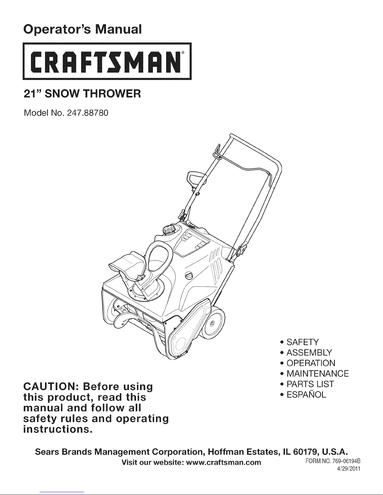
21" SNOW THROWER
Model No. 247.88780
CAUTION: Before using
this product, read this
manual and follow all
safety rules and operating
instructions.
Sears Brands Management Corporation, Hoffman Estates, IL 60179, U.S.A.
Visit our website: www.craftsman.com FORM1/O.769-06194B
o SAFETY
ASSEMBLY
OPERATION
MAINTENANCE
PARTS LIST
o ESPANOL
4/29/2011
Page 2
WarrantyStatement..................................Pac
SafeOperationPractices..........................Pac
SafetyLabels............................................Pac
Assembly..................................................Pac
Operation..................................................Pac
ServiceandMaintenance.........................Pac
Off-SeasonStorage..................................Pac
e2
es3-6
e7
es8-10
es11-13
es14-18
e19
TroubleShooting.......................................Page20
PartsList...................................................Pages24-27
EnginePartsList.......................................Pages28-31
Labels.......................................................Page32
RepairProtectionAgreement...................Page36
Espa_ol.....................................................Page37
ServiceNumbers......................................BackCover
CRAFTSMANTWOYEAR FULL WARRANTY
FORTWOYEARSfromthe dateof purchase,this productiswarrantedagainstanydefectsin materialorworkmanship.Defectiveproductwill
receivefreerepairorfree replacementifrepairisunavailable.
Thiswarrantyisvoidif thisproductiseverusedwhile providingcommercialservicesorifrentedtoanotherperson.
Forwarranty coverage details to obtain repairor replacement,visit the website: www.craftsman.com
This warranty covers ONLYdefects in material andworkmanship. Warrantycoverage does NOTinclude:
• Expendableitemsthatcanwearoutfromnormalusewithinthewarrantyperiod,includingbutnotlimitedto augers,augerpaddles,drift
cutters,skidshoes,shaveplate,shearpins,sparkplug,air cleaner,belts,andoil filter.
• Standardmaintenanceservicing,oilchanges,ortune-ups.
• Tire replacementor repaircausedby puncturesfromoutsideobjects,suchasnails,thorns,stumps,orglass.
• Tireor wheelreplacementor repairresultingfromnormalwear,accident,orimproperoperationormaintenance.
• Repairsnecessarybecauseof operatorabuse,includingbutnotlimitedtodamagecausedbyover-speedingtheengine,or fromimpacting
objectsthatbendthe frame,augershaft,etc.
• Repairsnecessarybecauseof operatornegligence,includingbutnotlimitedto,electricalandmechanicaldamagecausedbyimproper
storage,failureto usethe propergradeandamountofengineoil, or failureto maintaintheequipmentaccordingto theinstructionscontained
intheoperator'smanual.
• Engine(fuelsystem)cleaningor repairscausedbyfuel determinedto becontaminatedoroxidized(stale).Ingeneral,fuelshouldbeused
within30 daysof itspurchasedate.
• Normaldeteriorationandwearof theexteriorfinishes,orproductlabelreplacement.
Thiswarrantygivesyouspecificlegalrights,andyou mayalsohaveotherrightswhichvaryfromstatetostate.
Sears Brands Management Corporation, Hoffman Estates, IL 60179
EngineOilType: SAE5W-30
EngineOilCapacity: 20ounces
FuelCapacity: 2 Quarts
SparkPlug: F6RTC
SparkPlugGap: .020"-.030"
©SearsBrands,LLC
Model Number.................................................................
Serial Number .................................................................
Dateof Purchase.............................................................
Recordthemodelnumber,serialnumber
anddateof purchaseabove
2
Page 3
Thissymbolpointsout importantsafetyinstructionswhich,if not
followed,couldendangerthepersonalsafetyand/orpropertyof
yourselfandothers. Readandfollowall instructionsin thismanual
beforeattemptingtooperatethismachine.Failuretocomplywith
theseinstructionsmayresultin personalinjury.Whenyouseethis
symbol,HEEDITSWARNING!
Thismachinewasbuiltto beoperatedaccordingtothesafeopera-
tionpracticesinthis manual.Aswithanytypeof powerequipment,
carelessnessorerroron thepartoftheoperatorcanresultin serious
injury.Thismachineiscapableofamputatingfingers,hands,toes
andfeetandthrowingdebris.Failuretoobservethefollowingsafety
instructionscouldresultin seriousinjuryor death.
CALIFORNIA PROPOSITION 65
EngineExhaust,someof itsconstituents,andcertainvehicle
componentscontainoremitchemicalsknowntoStateofCalifornia
tocausecancerandbirthdefectsorotherreproductiveharm,
TRAiNiNG
• Read,understand,andfollowall instructionsonthemachineand
in themanual(s)beforeattemptingto assembleandoperate.
Failuretodo socan resultinseriousinjurytotheoperatorand/
orbystanders.Keepthismanualin a safeplaceforfutureand
regularreferenceandfor orderingreplacementparts. Forques-
tionscall,1-800-4MY-HOME.
• Befamiliarwithall controlsandtheirproperoperation.Knowhow
tostopthe machineanddisengagethemquickly.
Neverallowchildrenunder14yearsofageto operatethis
machine.Children14andover shouldreadandunderstandthe
instructionsandsafeoperationpracticesin thismanualandon
themachineandbe trainedandsupervisedbyanadult.
Neverallowadultsto operatethismachinewithoutproper
instruction.
• Thrownobjectscancauseseriouspersonalinjury.Planyour
snow-throwingpatterntoavoiddischargeof materialtoward
roads,bystandersandthe like.
Keepbystanders,petsandchildrenat least75feetfromthe
machinewhileitisinoperation.Stopmachineifanyoneenters
thearea.
Exercisecautiontoavoidslippingor falling,especiallywhen
operatinginreverse.
Your Responsibility--Restrict the useof thispowermachineto
personswhoread,understandandfollowthewarningsandinstruc-
tionsin thismanualandon the machine,
SAVE THESE INSTRUCTIONS!
PREPARATION
Thoroughlyinspecttheareawheretheequipmentistobeused.
Removeall doormats,newspapers,sleds,boards,wiresandother
foreignobjects,whichcouldbe trippedoverorthrownbythe auger/
impeller.
Alwayswearsafetyglassesoreyeshieldsduringoperationand
whileperformingan adjustmentor repairto protectyoureyes.
Thrownobjectswhichricochetcancauseseriousinjurytothe
eyes.
Donot operatewithoutwearingadequatewinteroutergarments.
Donot wearjewelry,longscarvesorotherlooseclothing,which
couldbecomeentangledinmovingparts.Wearfootwearwhich
willimprovefootingonslipperysurfaces.
Usea groundedthree-wireextensioncordand receptaclefor all
machineswithelectricstartengines.
Disengageallcontrolleversbeforestartingtheengine.
Neverattempttomakeanyadjustmentswhileengineis running,
exceptwherespecificallyrecommendedintheoperator'smanual.
Letengineandmachineadjustto outdoortemperaturebefore
startingtoclearsnow.
3
Page 4
SafeHandling of Gasoline
Toavoidpersonalinjuryor propertydamageuseextremecarein
handlinggasoline.Gasolineisextremelyflammableandthevaporsare
explosive.Seriouspersonalinjurycan occurwhengasolineisspilled
onyourselforyourclotheswhichcan ignite. Washyourskinand
changeclothesimmediately.
• Useonlyan approvedgasolinecontainer.
• Extinguishallcigarettes,cigars,pipesandothersourcesof
ignition.
• Neverfuel machineindoors.
• Neverremovegascapor addfuel whilethe engineishotor
running.
• Allowenginetocoolat leasttwo minutesbeforerefueling.
• Neveroverfillfueltank.Fill tankto nomorethan1/2inchbelow
bottomoffillerneckto providespaceforfuelexpansion.
• Replacegasolinecapandtightensecurely.
• Ifgasolineisspilled,wipe itoff theengineandequipment.Move
machinetoanotherarea.Wait5 minutesbeforestartingthe
engine.
• Neverstorethe machineorfuelcontainerinsidewherethereisan
openflame,sparkor pilotlight(e.g.furnace,waterheater,space
heater,clothesdryeretc.).
• Allowmachineto coolat least5 minutesbeforestoring.
• Neverfill containersinsidea vehicleor ona truckor trailerbed
witha plasticliner.Alwaysplacecontainersonthe groundaway
fromyourvehiclebeforefilling.
• If possible,removegas-poweredequipmentfromthetruckor
trailerandrefuelitonthe ground.Ifthis is notpossible,thenrefuel
suchequipmentonatrailerwitha portablecontainer,ratherthan
froma gasolinedispensernozzle.
• Keepthe nozzleincontactwiththerimofthe fueltankor
containeropeningatalltimesuntilfuelingis complete.Donotuse
a nozzlelock-opendevice.
OPERATION
• Do notputhandsorfeetnear rotatingparts,in theauger/impeller
housingorchuteassembly.Contactwiththe rotatingpartscan
amputatehandsandfeet.
• Theauger/impellercontrolleverisa safetydevice.Neverbypass
itsoperation.Doingsomakesthe machineunsafeandmaycause
personalinjury.
• Thecontrolleversmustoperateeasilyin bothdirectionsand
automaticallyreturntothedisengagedpositionwhenreleased.
• Neveroperatewitha missingordamagedchuteassembly.Keep
all safetydevicesinplaceandworking.
• Neverrunanengineindoorsor ina poorlyventilatedarea.Engine
exhaustcontainscarbonmonoxide,anodorlessanddeadlygas.
• Do notoperatemachinewhileundertheinfluenceofalcoholor
drugs.
• Mufflerandenginebecomehotandcancauseaburn.Donot
touch.Keepchildrenaway.
• Exerciseextremecautionwhenoperatingonorcrossinggravel
surfaces.Stayalertforhiddenhazardsortraffic.
Exercisecautionwhenchangingdirectionandwhileoperatingon
slopes.
Planyoursnow-throwingpatternto avoiddischargetowards
windows,walls,carsetc.Thus,avoidingpossibleproperty
damageorpersonalinjurycausedby a ricochet.
Neverdirectdischargeatchildren,bystandersandpetsorallow
anyoneinfrontof themachine.
Donot overloadmachinecapacitybyattemptingtoclearsnowat
toofastof a rate.
Neveroperatethismachinewithoutgoodvisibilityorlight.Always
be sureof yourfootingand keepa firmholdon thehandles.Walk,
neverrun.
Disengagepowertotheauger/impellerwhentransportingor not
in use.
Neveroperatemachineathightransportspeedsonslippery
surfaces.Lookdownand behindandusecarewhenbackingup.
Ifthemachineshouldstartto vibrateabnormally,stopthe engine,
disconnectthe sparkplugwireandgroundit againsttheengine.
Inspectthoroughlyfordamage.Repairanydamagebefore
startingandoperating.
Disengageallcontrolleversandstopenginebeforeyouleave
theoperatingposition(behindthehandles).Waituntiltheauger/
impellercomestoa completestopbeforeuncloggingthechute
assembly,makinganyadjustments,or inspections.
Neverputyourhandinthedischargeorcollectoropenings.Do
notunclogchuteassemblywhileengineis running.Shutoff
engineand remainbehindhandlesuntilall movingpartshave
stoppedbeforeunclogging.
Useonlyattachmentsandaccessoriesapprovedbythemanufac-
turer(e.g.wheelweights,tirechains,cabsetc.).
Whenstartingengine,pullcord slowlyuntilresistanceis felt,then
pull rapidly.Rapidretractionof startercord(kickback)willpull
handandarmtowardenginefasterthanyoucanlet go.Broken
bones,fractures,bruisesorsprainscouldresult.
Ifsituationsoccurwhichare notcoveredinthis manual,usecare
andgoodjudgment.ContactCustomerSupportforassistance
andthenameofyour nearestservicingdealer.
CLEARING A CLOGGED DISCHARGE CHUTE
Handcontactwiththe rotatingimpellerinsidethe dischargechute
is the mostcommoncauseofinjuryassociatedwithsnowthrowers.
Neveruseyourhandtocleanoutthedischargechute.
Toclear thechute:
1. SHUTTHEENGINEOFF!
2. Wait 10secondstobe surethe impellerbladeshavestopped
rotating.
3. Alwaysusea clean-outtool,notyourhands.
4
Page 5

MAINTENANCE & STORAGE
• Nevertamperwithsafetydevices.Checktheirproperoperation
regularly.Refertothemaintenanceandadjustmentsectionsof
thismanual.
• Beforecleaning,repairing,or inspectingmachinedisengageall
controlleversandstoptheengine.Waituntilthe auger/impeller
cometoa completestop.Disconnectthe sparkplugwireand
groundagainsttheengineto preventunintendedstarting.
Checkboltsand screwsforpropertightnessatfrequentintervals
tokeepthemachineinsafeworkingcondition.Also,visually
inspectmachineforanydamage.
Donotchangetheenginegovernorsettingor over-speedthe
engine.Thegovernorcontrolsthe maximumsafeoperatingspeed
ofthe engine.
Snowthrowershaveplatesandskidshoesaresubjecttowear
anddamage.Foryoursafetyprotection,frequentlycheckall
componentsandreplacewithoriginalequipmentmanufacturer's
(OEM)partsonly.Useof partswhichdo notmeetthe original
equipmentspecificationsmayleadto improperperformanceand
compromisesafety!
Checkcontrolleversperiodicallytoverifytheyengageanddisen-
gageproperlyandadjust,ifnecessary.Refertotheadjustment
sectioninthisoperator'smanualforinstructions.
Maintainorreplacesafetyandinstructionlabels,asnecessary.
• Observeproperdisposallawsand regulationsforgas,oil,etc.to
protecttheenvironment.
Priorto storing,runmachineafewminutestoclear snowfrom
machineandpreventfreezeupof auger/impeller.
Neverstorethemachineorfuel containerinsidewherethereisan
openflame,sparkorpilot lightsuchas a waterheater,furnace,
clothesdryeretc.
Alwaysrefertothe operator'smanualforproperinstructionson
off-seasonstorage.
Checkfuelline,tank, cap,andfittingsfrequentlyforcracksor
leaks.Replaceif necessary.
Donotcrankenginewithsparkplugremoved.
AccordingtotheConsumerProductsSafetyCommission(CPSC)
andtheU.S.EnvironmentalProtectionAgency(EPA),thisproduct
hasan AverageUsefulLifeof seven(7)years,or 60 hoursof
operation.At theendof theAverageUsefulLifehavethe machine
inspectedannuallybyan authorizedservicedealertoensurethat
allmechanicalandsafetysystemsareworkingproperlyand not
wornexcessively.Failuretodo socanresultinaccidents,injuries
ordeath.
DO NOT MODIFY ENGINE
Toavoidseriousinjuryor death,do not modifyengineinany way.
Tamperingwiththegovernorsettingcanleadto a runawayengineand
causeitto operateat unsafespeeds.Nevertamperwithfactorysetting
ofenginegovernor.
NOTICE REGARDING EMISSIONS
EngineswhicharecertifiedtocomplywithCaliforniaandfederal
EPAemissionregulationsforSORE(SmallOffRoadEquipment)are
certifiedto operateonregularunleadedgasoline,and mayinclude
thefollowingemissioncontrolsystems:EngineModification(EM),
OxidizingCatalyst(OC),SecondaryAirInjection(SAI)and ThreeWay
Catalyst(TWO)if soequipped.
SPARK ARRESTOR
Thismachineisequippedwithaninternalcombustionengineand
shouldnotbe usedonor nearany unimprovedforest-covered,
brush-coveredorgrass-coveredlandunlesstheengine'sexhaust
systemisequippedwitha sparkarrestormeetingapplicablelocalor
statelaws(if any)
Ifa sparkarrestorisused,it shouldbe maintainedin effectiveworking
orderbytheoperator.Inthe StateofCaliforniatheaboveis required
bylaw (Section4442ofthe CaliforniaPublicResourcesCode).Other
statesmayhavesimilarlaws. Federallawsapplyonfederallands.
A sparkarrestorforthemufflerisavailablethroughyournearestSears
PartsandRepairServiceCenter.
Page 6
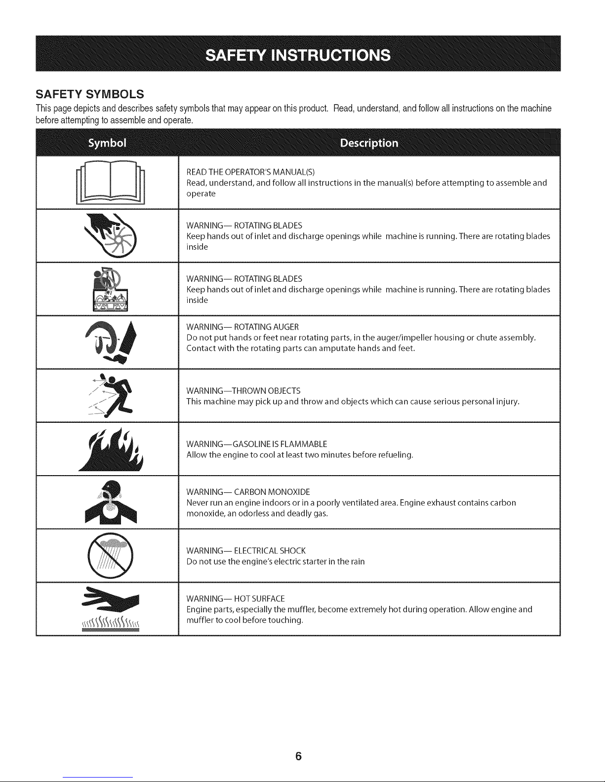
SAFETY SYMBOLS
Thispagedepictsanddescribessafetysymbolsthatmayappearonthisproduct. Read,understand,andfollowall instructionsonthemachine
beforeattemptingtoassembleandoperate.
READ THE OPERATOR'S MANUAL(S)
i
i
Read, understand, and follow all instructions in the manual(s) before attempting to assemble and
operate
WARNING-- ROTATING BLADES
Keep hands out of inlet and discharge openings while machine is running. There are rotating blades
inside
WARNING-- ROTATING BLADES
Keep hands out of inlet and discharge openings while machine is running. There are rotating blades
inside
WARNING-- ROTATING AUGER
Do not put hands or feet near rotating parts, in the auger/impeller housing or chute assembly.
Contact with the rotating parts can amputate hands and feet.
WARNING--THROWN OBJECTS
This machine may pick up and throw and objects which can cause serious personal injury.
WARNING--GASOLINE ISFLAMMABLE
Allow the engine to cool at least two minutes before refueling.
WARNING-- CARBON MONOXIDE
Never run an engine indoors or in a poorly ventilated area. Engine exhaust contains carbon
monoxide, an odorless and deadly gas.
WARNING-- ELECTRICAL SHOCK
Do not use the engine's electric starter in the rain
WARNING-- HOT SURFACE
Engine parts, especially the muffler, become extremely hot during operation. Allow engine and
muffler to cool before touching.
6
Page 7
NOTE:All referencesto theleftorrightsideof thesnowthrowerare
fromtheoperator'sposition.Anyexceptionswillbe noted.
UNPACKING THE SNOW THROWER
1. Openthetop ofthe carton.
2. Cutdownthecornersonthefrontofthecartonandfolddownthe
frontside.
3. Pullthesnowthroweroutofthe carton.Besure notto damage
thechute,or anycablesattachedtothe chute,whichis shipped
undertheshroudonthebacksideofthe carton.
ASSEMBLY
Positioning the Upper Handle
1. Removethewingknobsandcarriageboltsfromthetopofthelower
handle.SeeFigure1.Itisnotnecessaryto removetheshoulder
screwandflangelocknutbelowthewingknobandcarriagebolt.
3. Tightenthepreviouslyremovedhardwaretosecurethe handlein
place.SeeFigure2.
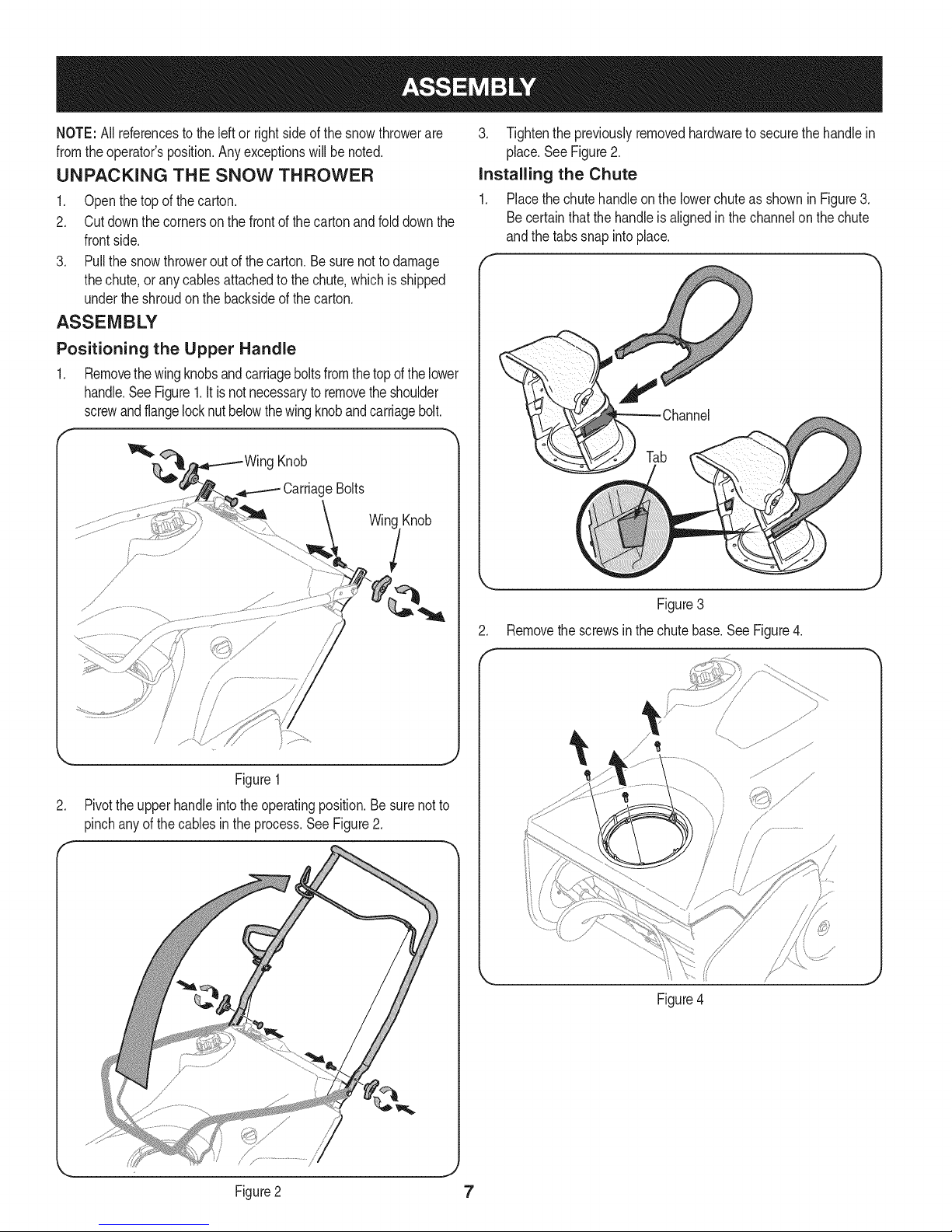
installing the Chute
1. PlacethechutehandleonthelowerchuteasshowninFigure3.
Becertainthatthehandleis alignedinthechannelonthechute
andthetabssnap intoplace.
f
g Knob
CarriageBolts
Win(
i
i
/
Figure1
.
Pivottheupperhandleintotheoperatingposition.Besurenotto
pinchanyof thecablesintheprocess.SeeFigure2.
Tab
Figure3
2. Removethe screwsinthechutebase.SeeFigure4.
/ _
/ /, .......
Figure2
Figure4
7
Page 8
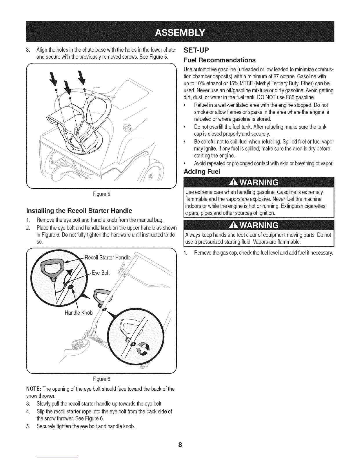
.
Aligntheholes inthechutebasewiththe holesinthelowerchute
andsecurewiththepreviouslyremovedscrews.SeeFigure5.
f
SET-UP
Fuel Recommendations
Useautomotivegasoline(unleadedorlowleadedto minimizecombus-
tionchamberdeposits)withaminimumof87 octane.Gasolinewith
upto10%ethanolor 15%MTBE(MethylTertiaryButylEther)canbe
used.Neverusean oil/gasolinemixtureordirty gasoline.Avoidgetting
dirt, dust,orwaterinthe fueltank.DONOTuse E85gasoline.
• Refuelinawell-ventilatedareawiththeenginestopped.Donot
smokeorallowflamesor sparksin theareawheretheengineis
refueledor wheregasolineisstored.
• Donotoverfillthefueltank.Afterrefueling,makesurethetank
capis closedproperlyandsecurely.
• Becarefulnotto spillfuelwhenrefueling.Spilledfuelorfuelvapor
mayignite.Ifanyfuelisspilled,makesuretheareaisdrybefore
startingtheengine.
• Avoidrepeatedor prolongedcontactwithskinorbreathingofvapor.
Adding Fuel
Figure5
Installing the Recoil Starter Handle
1. Removetheeyeboltandhandleknobfromthemanualbag.
2. Placetheeyeboltand handleknobonthe upperhandleasshown
inFigure6. Donot fullytightenthehardwareuntil instructedtodo
SO.
HandleKnob
Useextremecarewhenhandlinggasoline.Gasolineis extremely
flammableandthe vaporsare explosive.Neverfuelthemachine
indoorsorwhilethe engineishotor running.Extinguishcigarettes,
lc gars,p pesandothersourcesof gnt on.
Alwayskeephandsandfeetclearofequipmentmovingparts.Donot
usea pressurizedstartingfluid.Vaporsareflammable.
1. Removethegascap,checkthefuellevelandaddfuelifnecessary.
Figure6
NOTE:The openingof theeye boltshouldfacetowardthebackof the
snowthrower.
3. Slowlypulltherecoilstarterhandleuptowardstheeye bolt.
4. Sliptherecoilstarterropeintotheeyeboltfromthebacksideof
thesnowthrower.SeeFigure6.
5. Securelytightentheeyeboltandhandleknob.
8
Page 9
Checking and Adding Oil
Theengineis shippedwithoutoil intheengine.Youmustfillthe
enginewithoil beforeoperating.Runningtheenginewithinsufficient
_o cancauseserous engnedamageandvod the productwarranty.
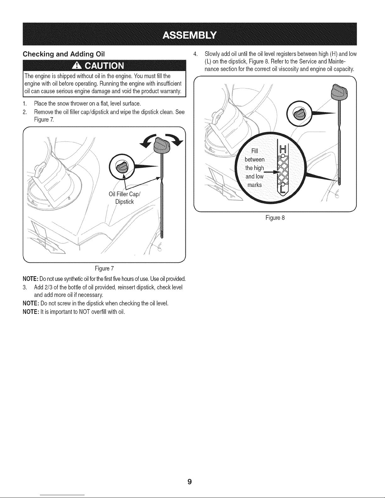
1. Placethe snowthroweronaflat,levelsurface.
2. Removetheoilfillercap/dipstickandwipethedipstickclean.See
Figure7.
...._J
ii
/
Oil FillerCap/
Dipstick
/
/
/
/
//
/
.
Slowlyaddoil untilthe oil levelregistersbetweenhigh(H) and low
(L) onthedipstick,Figure8. RefertotheServiceandMainte-
nancesectionforthe correctoil viscosityandengineoilcapacity.
Figure8
/
ij .....
Figure7
NOTE:Donotusesyntheticoilforthefirstfivehoursofuse.Useoilprovided.
3. Add2/3ofthebottleof oil provided,reinsertdipstick,checklevel
andaddmoreoil if necessary.
NOTE:Donotscrewinthedipstickwhencheckingtheoil level.
NOTE:Itisimportantto NOToverfillwithoil.
9
Page 10
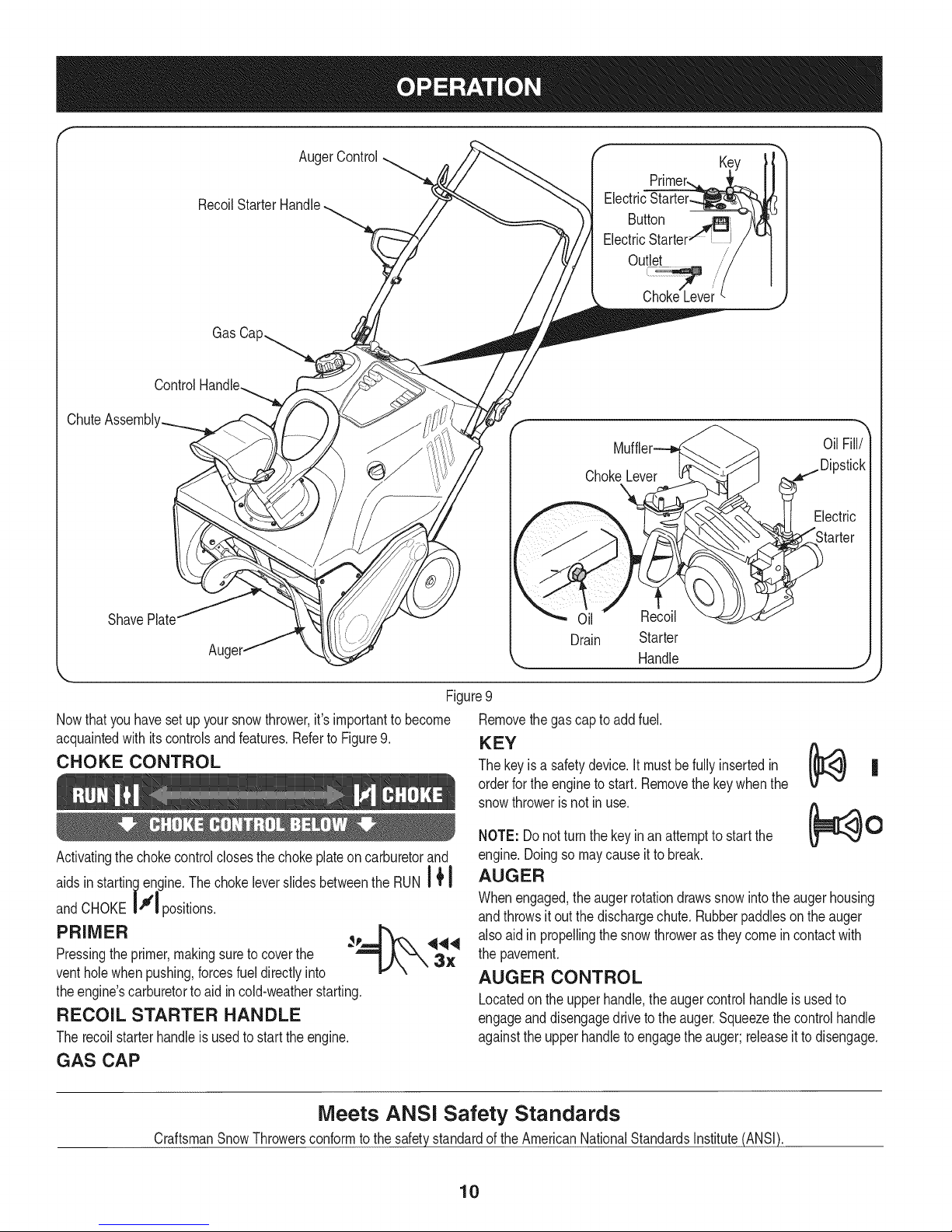
ChuteAssembl'
AugerControl
Recoil
GasCa
Control
Oil
ShavePlate
Aug{
Figure9
Nowthat youhavesetup yoursnowthrower,it'simportanttobecome
acquaintedwithitscontrolsandfeatures.RefertoFigure9.
CHOKE CONTROL
Activatingthechokecontrolclosesthe chokeplateoncarburetorand
aidsinstartingengine.Thechokeleverslidesbetweenthe RUNI { I
I
andCHOKE|f_ positions.
PRIMER __ ,q_,q
Pressingtheprimer,makingsureto coverthe
ventholewhenpushing,forcesfueldirectlyinto _-'X 3X
theengine'scarburetortoaid incold-weatherstarting.
RECOIL STARTER HANDLE
Therecoilstarterhandleisusedto starttheengine.
GAS CAP
Handle
Removethegascaptoaddfuel.
KEY
Thekeyis a safetydevice.It mustbefullyinsertedin
orderfortheenginetostart.Removethekeywhenthe
snowthrowerisnot inuse.
NOTE:Do notturn thekeyinanattemptto startthe
engine.Doingsomaycauseit tobreak.
AUGER
Whenengaged,theaugerrotationdrawssnowintotheaugerhousing
andthrowsit outthe dischargechute.Rubberpaddlesontheauger
alsoaidin propellingthesnowthrowerastheycomein contactwith
thepavement.
AUGER CONTROL
Locatedontheupperhandle,theaugercontrolhandleisusedto
engageanddisengagedrivetothe auger.Squeezethecontrolhandle
againsttheupperhandleto engagethe auger;releaseitto disengage.
Meets ANSI Safety Standards
CraftsmanSnowThrowersconformtothesafetystandardofthe AmericanNationalStandardsInstitute(ANSI).
10
Page 11
CHUTE ASSEMBLY
Rotatethedischargechuteto theleftorrightusingthe controlhandle.
Thepitchof thedischargechutecontrolstheangleat whichthesnow
isthrown.Loosenthewingknobontheside ofthe dischargechute
beforepivotingthedischargechuteupwardordownward.Retighten
theknoboncethe desiredpositionhasbeenachieved.
SHAVE PLATE
Theshaveplate maintainscontactwiththepavementasthesnow
throwerispropelled,allowingsnowclosetothe pavement'ssurfaceto
bedischarged.
ELECTRIC STARTER OUTLET
Requirestheuseof athree-prongoutdoorextensioncordanda 120V
powersource/walloutlet.
ELECTRIC STARTER BUTTON
Pressingtheelectricstarterbuttonengagestheengine'selectric
starterwhenpluggedintoa 120Vpowersource.
OIL FILL/DiPSTICK
Engineoil levelcanbecheckedandoiladdedthroughtheoil fill.
OIL DRAIN
Engineoilcanbedrainedthroughtheoil drain.
MUFFLER
Engineexhaustexitstheenginevia themuffler.
BEFORE STARTING THE ENGINE
machineandin thismanualbefore
STARTING THE ENGINE
3ressurizedstartinc areflammable.
Toavoidcarbonmonoxidepoisoning,makesurethe engineis
outdoorsina well-ventilatedarea.
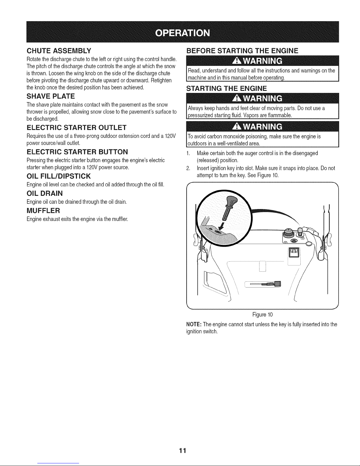
1. Makecertainboththe augercontrolisin thedisengaged
(released)position.
2. Insertignitionkeyintoslot.Makesureit snapsintoplace.Do not
attempttoturn thekey.See Figure10.
\
\ /
NOTE:Theenginecannotstartunlessthe keyisfullyinsertedintothe
ignitionswitch.
I J /
Figure10
11
Page 12
Electric Starter
Determinethatyourhome'swiringis a three-wiregroundedsystem.
Aska licensedelectricianifyouarenotcertain.
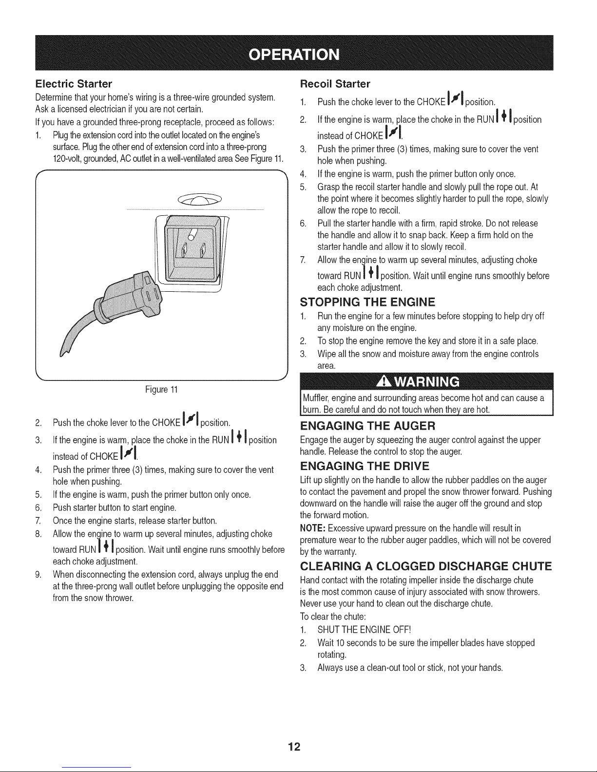
Ifyouhavea groundedthree-prongreceptacle,proceedas follows:
1. Plugtheextensioncordintotheoutletlocatedontheengine's
surface.Plugtheotherendofextensioncordintoathree-prong
120-volt,grounded,ACoutletinawell-ventilatedareaSeeFigure11.
Recoil Starter
1. Pushthechokeleverto theCHOKEIll position.
A
2. Iftheengineiswarm,placethechokeintheRUN_ I position
|+l
insteadofCHOKEI"rl.
3. Pushtheprimerthree(3) times,makingsuretocoverthevent
holewhenpushing.
4. Iftheengineiswarm,pushtheprimerbuttononlyonce.
5. Graspthe recoilstarterhandleandslowlypullthe ropeout.At
thepointwhereit becomesslightlyharderto pullthe rope,slowly
allowthe ropeto recoil.
6. Pullthestarterhandlewitha firm,rapidstroke.Donotrelease
thehandleandallowit to snapback. Keepa firm holdon the
starterhandleandallow itto slowlyrecoil.
7. Allowtheenginetowarmupseveralminutes,adjustingchoke
towardRUN| _position.Waituntilenginerunssmoothlybefore
eachchokeadjustment.
STOPPING THE ENGINE
1. Runtheenginefora fewminutesbeforestoppingtohelpdry off
anymoistureontheengine.
2. Tostoptheengineremovethekeyand storeit inasafeplace.
3. Wipeallthesnowandmoistureawayfromtheenginecontrols
area.
|+I
Figure11
2. Pushthe chokeleverto theCHOKEI"#1 position.
a ii
3. Iftheengineis warm,placethechokeintheRUN_ I position
insteadofCHOKEIII.
4. Pushthe primerthree(3)times,makingsuretocoverthevent
holewhenpushing.
5. Iftheengineis warm,pushtheprimerbuttononlyonce.
6. Pushstarterbuttontostart engine.
7. Oncethe enginestarts,releasestarterbutton.
8. Allowtheenginetowarmupseveralminutes,adjustingchoke
towardRUN| _position.Waituntilenginerunssmoothlybefore
eachchokeadjustment.
9. Whendisconnectingtheextensioncord,alwaysunplugtheend
atthe three-prongwalloutletbeforeunpluggingthe oppositeend
fromthesnowthrower.
|+I
Muffler,engineandsurroundingareasbecomehotandcancausea
burn.Becarefulanddonot touchwhenthe_arehot.
ENGAGING THE AUGER
Engagethe augerbysqueezingtheaugercontrolagainsttheupper
handle.Releasethecontroltostopthe auger.
ENGAGING THE DRIVE
Liftupslightlyonthe handletoallowtherubberpaddiesontheauger
tocontactthe pavementand propelthe snowthrowerforward.Pushing
downwardonthe handlewill raisetheaugeroff the groundandstop
theforwardmotion.
NOTE:Excessiveupwardpressureonthehandlewillresultin
prematureweartothe rubberaugerpaddies,whichwillnotbecovered
bythe warranty.
CLEARING A CLOGGED DISCHARGE CHUTE
Handcontactwiththe rotatingimpellerinsidethedischargechute
isthe mostcommoncauseofinjuryassociatedwithsnowthrowers.
Neveruseyourhandtocleanoutthedischargechute.
Toclear thechute:
1. SHUTTHEENGINEOFF!
2. Wait 10secondstobe surethe impellerbladeshavestopped
rotating.
3. Alwaysusea clean-outtoolor stick,notyourhands.
12
Page 13
MAINTENANCE SCHEDULE
Beforeperforminganytypeof maintenance/service,disengageall
controlsandstopthe engine.Waituntilall movingpartshavecome
toa completestop.Disconnectsparkplugwireandgroundit against
theengineto preventunintendedstarting.Alwayswearsafetyglasses
duringoperationorwhileperforminganyadjustmentsor repairs.
Eachuse .
1st5 hours 1. 1. Change.
Every5hours 1. 1. Check.
25 hours 1. 2. Check.
Everyseason/50hours 1. 1. Change
Everyseason/100hours 1. 1. Clean,replace,re-gap
Everyseason/Before 1. 1. Lubricate
storage 2. 2. Lubricate
Engineoillevel.
2.
Snowthrowerandexhaust
area.
Engineoil.
Engineoil.
Exhaustarea.
2. 2. Clean.
Sparkplug.
Engineoil
Sparkplug
Pivotpoints
Controlhandle
3. 3. Lubricate
Extensionspring
1. Check
2. Clean
ENGINE MAINTENANCE
usedoil.
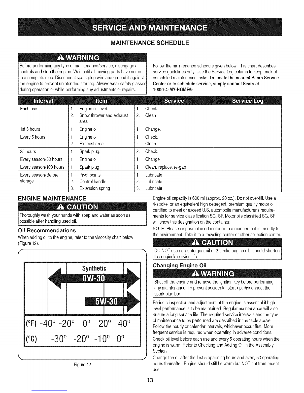
Oil Recommendations
Whenaddingoilto theengine,referto theviscositychartbelow
(Figure12).
Followthemaintenanceschedulegivenbelow.Thischartdescribes
serviceguidelinesonly.UsetheServiceLogcolumntokeeptrackof
completedmaintenancetasks.To locate the nearest Sears Service
Centeror to scheduleservice,simplycontactSearsat
1-800-4-MY-HOME®.
= =
Engineoilcapacityis600ml(approx.20oz.). Donotover-fill.Usea
4-stroke,oran equivalenthighdetergent,premiumqualitymotoroil
certifiedto meetor exceedU.S.automobilemanufacturer'srequire-
mentsfor serviceclassificationSG,SEMotoroils classifiedSG,SF
willshowthis designationon thecontainer.
NOTE:Pleasedisposeofusedmotoroilina mannerthatisfriendlyto
theenvironment.Takeittoa recyclingcenteror othercollectioncenter.
DONOTusenon-detergentoilor2-strokeengineoil.It couldshorten
theengine'sservicelife.
Synthetic
("F)-40o-20o 0o 200 400
(°c) -30° -20° -10° 0°
Figure12
Changing Engine Oil
Shutoffthe engineand removethe ignitionkeybeforeperforming
anymaintenance.Topreventaccidentalstart-up,disconnectthe
sparkplugboot.
Periodicinspectionandadjustmentoftheengineis essentialif high
levelperformanceis tobemaintained.Regularmaintenancewillalso
ensurea longservicelife.Therequiredserviceintervalsandthe type
of maintenancetobe performedaredescribedin the tableabove.
Followthehourlyorcalendarintervals,whicheveroccurfirst.More
frequentserviceis requiredwhenoperatinginadverseconditions.
Checkoil levelbeforeeachuseandevery5 operatinghourswhenthe
engineiswarm.RefertoCheckingandAddingOilintheAssembly
Section.
Changetheoil afterthefirst5 operatinghoursandevery50 operating
hoursthereafter.EngineshouldstillbewarmbutNOThotfrom recent
use.
13
Page 14
.
Drainfuelfromthetankby runningtheengineuntilthefueltankis
empty.Besurethe fuelfill capis secure.
2.
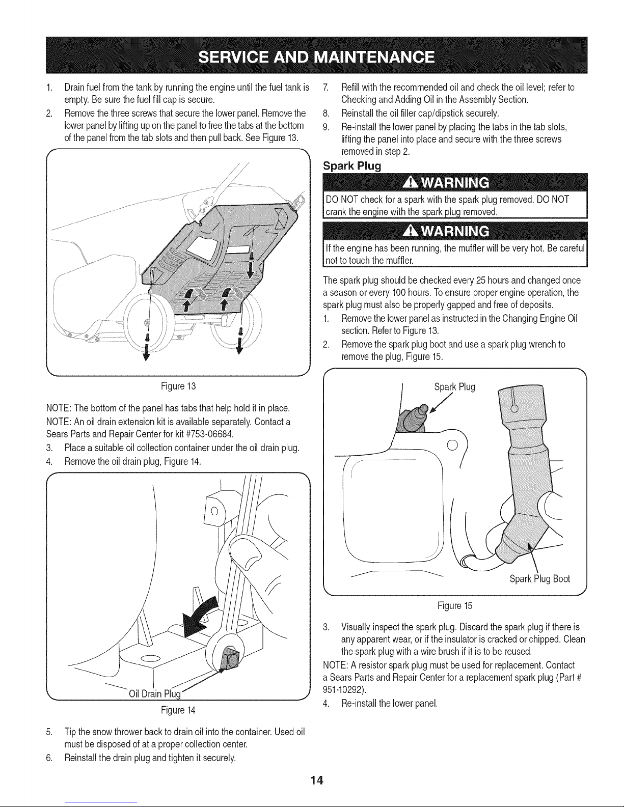
Removethethreescrewsthatsecurethelowerpanel.Removethe
lowerpanelbyliftinguponthepaneltofreethetabsatthe bottom
ofthepanelfromthetab slotsandthenpullback.SeeFigure13.
7. Refillwiththe recommendedoiland checktheoil level;referto
CheckingandAddingOil intheAssemblySection.
8. Reinstallthe oil fillercap/dipsticksecurely.
9. Re-installthe lowerpanelbyplacingthetabs inthetab slots,
liftingthepanelintoplaceandsecurewiththe threescrews
removedinstep2.
Spark Plug
DONOTcheck fora sparkwiththe sparkplugremoved.DONOT
cranktheenginewiththe sparkplugremoved.
Iftheenginehas beenrunning,the mufflerwillbeveryhot. Becareful
notto touchthemuffler.
Thesparkplugshouldbecheckedevery25hoursandchangedonce
a seasonor every100hours.Toensureproperengineoperation,the
sparkplugmustalso beproperlygappedandfreeof deposits.
1. RemovethelowerpanelasinstructedintheChangingEngineOil
section.RefertoFigure13.
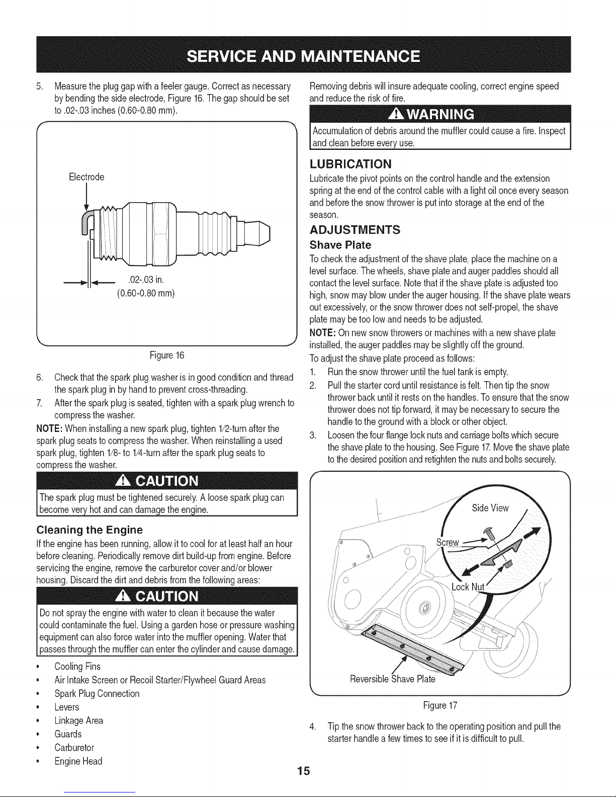
2. Removethe sparkplugbootand usea sparkplugwrenchto
removetheplug,Figure15.
Figure13
NOTE:Thebottomof thepanelhastabsthathelpholdit in place.
NOTE:Anoil drainextensionkitisavailableseparately.Contacta
SearsPartsand RepairCenterforkit#753-06684.
3. Placea suitableoilcollectioncontainerundertheoildrainplug.
4. Removetheoil drainplug,Figure14.
F 1
k,_ Oil DrainPlug" .,,
Figure14
SparkPlug
,J
SparkPlugBoot
Figure15
3. Visuallyinspectthe sparkplug.Discardthe sparkplugifthereis
anyapparentwear,oriftheinsulatoriscrackedorchipped.Clean
thesparkplugwitha wire brushif it is tobe reused.
NOTE:Aresistorsparkplugmustbeusedforreplacement.Contact
a SearsPartsandRepairCenterfora replacementsparkplug(Part#
951-10292).
4. Re-installthe lowerpanel.
5. Tipthesnowthrowerbacktodrainoilintothecontainer.Usedoil
mustbedisposedof ata propercollectioncenter.
6. Reinstallthedrainplugandtightenit securely.
14
Page 15
.
Measurethepluggapwitha feelergauge.Correctasnecessary
bybendingthesideelectrode,Figure16.Thegapshouldbeset
to.02-.03inches(0.60-0.80turn).
Electrode
.02-.03in.
(0.60-0.80ram)
_J
Figure16
6. Checkthatthesparkplugwasherisingoodconditionandthread
thesparkplugin by handtopreventcross-threading.
7. Afterthe sparkplugis seated,tightenwitha sparkplugwrenchto
compressthewasher.
NOTE:Wheninstallinga newsparkplug,tighten1/2-turnafterthe
sparkplugseatsto compressthe washer.Whenreinstallinga used
sparkplug,tighten1/8-to 1/4-turnafterthesparkplugseatsto
compressthewasher.
Removingdebriswillinsureadequatecooling,correctenginespeed
and reducetheriskoffire.
Accumulationofdebrisaroundthemufflercouldcausea fire.Inspect
andcleanbeforeeveryuse.
LUBRICATION
Lubricatethe pivotpointson thecontrolhandleandthe extension
springat theendof thecontrolcablewitha lightoilonceeveryseason
and beforethesnowthrowerisput intostorageat theendof the
season.
ADJUSTMENTS
Shave Plate
Tochecktheadjustmentoftheshaveplate,placethemachineona
levelsurface.Thewheels,shaveplateandaugerpaddlesshouldall
contactthelevelsurface.Notethat ifthe shaveplateis adjustedtoo
high,snowmayblowundertheaugerhousing.Ifthe shaveplatewears
outexcessively,orthesnowthrowerdoesnot self-propel,theshave
platemaybetoo lowandneedstobeadjusted.
NOTE:Onnewsnowthrowersormachineswithanewshaveplate
installed,theaugerpaddlesmaybeslightlyoff theground.
Toadjustthe shaveplateproceedasfollows:
1. Runthe snowthroweruntilthe fueltankis empty.
2. Pullthestartercorduntilresistanceisfelt.Thentip thesnow
throwerbackuntilit restsonthe handles.To ensurethatthe snow
throwerdoesnot tipforward,it maybe necessarytosecurethe
handletothe groundwitha blockorotherobject.
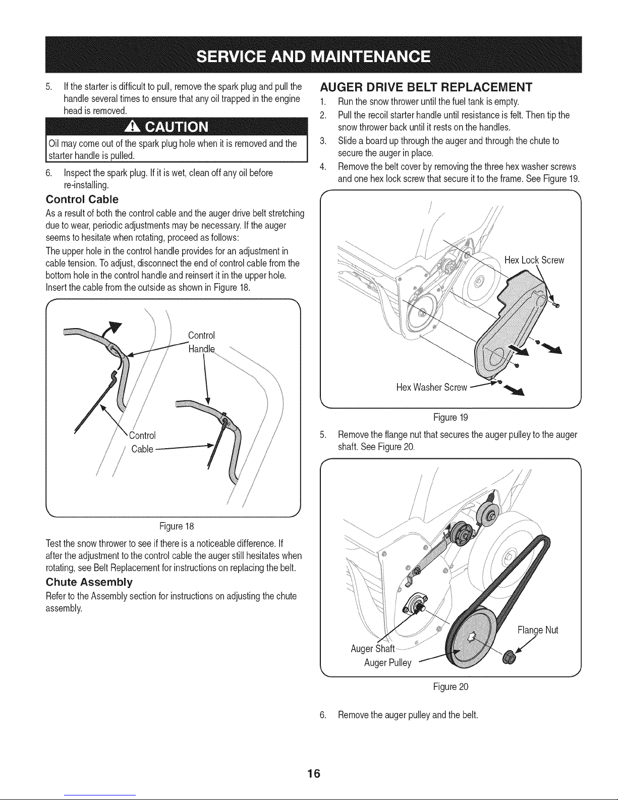
3. Loosenthefourflangelocknutsandcarriageboltswhichsecure
theshaveplatetothe housing.SeeFigure17.Movetheshaveplate
tothe desiredpositionandretightenthenutsandboltssecurely.
Thesparkplugmustbetightenedsecurely.Aloosesparkplugcan
becomeveryhotandcan damagetheengine.
Cleaning the Engine
Iftheenginehasbeenrunning,allowitto coolfor atleasthalfan hour
beforecleaning.Periodicallyremovedirtbuild-upfromengine.Before
servicingtheengine,removethecarburetorcoverand/orblower
housing.Discardthedirtand debrisfromthefollowingareas:
Donot spraytheenginewithwaterto cleanit becausethewater
couldcontaminatethefuel.Usinga gardenhoseor pressurewashing
Iequipmentcanalsoforcewaterintothemuffleropening.Waterthat
[passesthroughthe muffercan enterthecy nderandcausedamage.]
* CoolingFins
* AirIntakeScreenor RecoilStarter/FlywheelGuardAreas
* SparkPlugConnection
* Levers
* LinkageArea
* Guards
* Carburetor
* EngineHead
SideView
y
/
i\
Ji
ReversibleShavePlate
J
Figure17
4. Tipthesnowthrowerbacktotheoperatingpositionandpullthe
starterhandlea fewtimestosee ifit isdifficultto pull.
15
Page 16
5, If thestarterisdifficulttopull,removethesparkplugandpullthe
handleseveraltimesto ensurethatany oiltrappedinthe engine
headisremoved,
Oilmaycomeoutof thesparkplugholewhen itis removedandthe
starterhandleis pulled.
6. Inspectthesparkplug. Ifit is wet,cleanoff anyoil before
re-installing.
Control Cable
Asa resultof boththecontrolcableandthe augerdrivebelt stretching
duetowear,periodicadjustmentsmaybenecessary.Iftheauger
seemsto hesitatewhenrotating,proceedas follows:
Theupperholeinthe controlhandleprovidesforanadjustmentin
cabletension.Toadjust,disconnectthe endofcontrolcablefromthe
bottomholein the controlhandleand reinsertit intheupperhole.
Insertthe cablefromtheoutsideas shownin Figure18.
Control
AUGER DRIVE BELT REPLACEMENT
1. Runthe snowthroweruntilthe fueltankisempty.
2. Pullthe recoilstarterhandleuntilresistanceisfelt.Thentipthe
snowthrowerbackuntilitrestson thehandles.
3. Slidea boardup throughtheaugerandthroughthechuteto
securetheaugerinplace.
4. Removethe beltcoverby removingthe threehexwasherscrews
andone hexlockscrewthatsecureitto theframe.SeeFigure19.
HexLockScrew
/ Cable
/ /
Figure18
Testthesnowthrowerto seeif thereisa noticeabledifference.If
aftertheadjustmenttothecontrolcabletheaugerstill hesitateswhen
rotating,seeBeltReplacementforinstructionsonreplacingthebelt.
Chute Assembly
Refertothe Assemblysectionforinstructionsonadjustingthechute
assembly.
HexWasherScrew.............:._o
Figure19
,
Removetheflangenutthat securestheaugerpulleytothe auger
shaft.SeeFigure20.
/
/
FlangeNut
AugerShaft
/
AugerPulley
Figure20
J
6. Removethe augerpulleyandthe belt.
16
Page 17
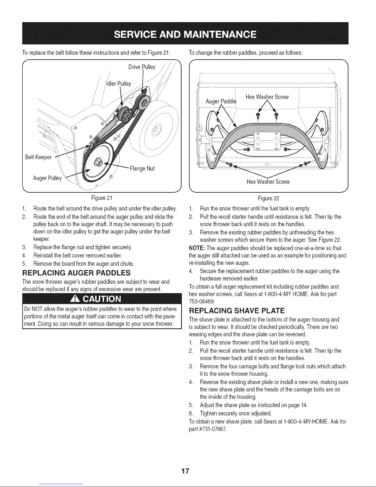
ToreplacethebeltfollowtheseinstructionsandrefertoFigure21: Tochangetherubberpaddles,proceedasfollows:
Drive
HexWasherScrew
Paddl_
HexWasherScrew
Figure21
1. Routethebeltaroundthedrivepulleyandundertheidlerpulley.
2. Routetheendofthebeltaroundtheaugerpulleyand slidethe
pulleybackon to theaugershaft.It maybe necessarytopush
downonthe idlerpulleyto gettheaugerpulleyunderthe belt
keeper.
3. Replacetheflangenutandtightensecurely.
4. Reinstallthebeltcoverremovedearlier.
5. Removethe boardfromtheaugerandchute.
REPLACING AUGER PADDLES
Thesnowthrowerauger'srubberpaddlesaresubjecttowearand
shouldbereplacedifany signsof excessiveweararepresent.
DoNOTallowtheauger'srubberpaddlesto wearto thepointwhere
Iportionsof themetalaugeritselfcancomein contactwiththe pave-
[ment.Doingsocan resultin seriousdamageto yoursnowthrower.
Figure22
1. Runthe snowthroweruntilthe fueltankis empty.
2. Pulltherecoilstarterhandleuntilresistanceisfelt.Thentip the
snowthrowerbackuntilit restson the handles.
3. Removethe existingrubberpaddlesbyunthreadingthehex
washerscrewswhichsecurethemto theauger.See Figure22.
NOTE:Theaugerpaddlesshouldbereplacedone-at-a-timesothat
theaugerstillattachedcanbeusedasanexamplefor positioningand
re-installingthenewauger.
4. Securethe replacementrubberpaddlestotheaugerusingthe
hardwareremovedearlier.
Toobtaina fullaugerreplacementkitincludingrubberpaddlesand
hexwasherscrews,callSearsat 1-800-4-MYHOME.Askforpart
753-06469.
REPLACING SHAVE PLATE
Theshaveplateisattachedtothe bottomof theaugerhousingand
is subjecttowear.Itshouldbecheckedperiodically.Therearetwo
wearingedgesandtheshaveplatecanbe reversed.
1. Runthe snowthroweruntilthe fueltankis empty.
2. Pulltherecoilstarterhandleuntilresistanceisfelt.Thentip the
snowthrowerbackuntilit restson the handles.
3. Removethe fourcarriageboltsandflangelocknutswhichattach
it to thesnowthrowerhousing.
4. Reversethe existingshaveplateorinstallanewone,makingsure
thenew shaveplateandthe headsofthecarriageboltsareon
theinsideofthe housing.
5. Adjustthe shaveplateas instructedon page14.
6. Tightensecurelyonceadjusted.
Toobtaina newshaveplate,call Searsat 1-800-4-MY-HOME.Askfor
part#731-07667.
17
Page 18

Ifthe snowthrowerwillnotbe usedfor30 daysor longer,or ifit isthe endofthe snowseasonwhenthe lastpossibilityof snowisgone,the
equipmentneedstobestoredproperly.Followstorageinstructionsbelowtoensuretopperformancefromthe snowthrowerformanymoreyears.
PREPARING THE ENGINE
Enginesstoredover30daysneedtobedrainedof fuelto prevent
deteriorationandgumfromforminginthefuelsystemoronessential
carburetorparts.If thegasolineinyourenginedeterioratesduring
storage,youmayneedto havethecarburetor,andotherfuelsystem
components,servicedorreplaced.
1. Removeall fuelfromthetankbyrunningtheengineuntilit stops.
2. Changetheengineoil.
3. Removethe sparkplugandpourapproximately1oz.(30 ml)of
cleanengineoil intothecylinder.Pullthe recoilstarterseveral
timesto distributetheoil,and reinstallthesparkplug.
4. Cleantheexterioroftheenginebydiscardingdirtanddebrisfrom
thefollowingareas:
Donot spraytheenginewithwaterto cleanit becausethewater
couldcontaminatethefuel.Usinga gardenhoseor pressurewashing
Iequipmentcanalsoforcewaterintothemuffleropening.Waterthat
[passesthroughthe muffercan enterthecy nderandcausedamage,j
• CoolingFins
• AirIntakeScreenorRecoilStarter/FlywheelGuardAreas
• SparkPlugConnection
• Levers
LinkageArea
Guards
Carburetor
EngineHead
5. Storeinaclean,dry andwellventilatedareaawayfromany
appliancethatoperateswitha flameor pilot light,suchasa
furnace,waterheateror clothesdryer.Avoidanyareawithaspark
producingelectricmotor,or wherepowertoolsareoperated.
PREPARING SNOW THROWER
Ifthesnowthrowerwill notbeusedfor30daysor longer,followthe
instructionsbelow.
1. Storetheequipmentinaclean,dryarea.
2. Wipedownthesnowthrowerwitha ragand removeanydirtor
debris.
3. Ifstoringthesnowthrowerinanunventilatedarea,rustproofthe
metalpartsofthe machinewithalightoil or siliconecoating.
Neverstoresnowthrowerwithfuel intank indoorsorinpoorlyventi-
latedareas,wherefuelfumesmayreachanopenflame,sparkor pilol
lightas ona furnace,waterheater,clothesdryer orgasappliance.
6. If possible,avoidstorageareaswithhighhumidity.
7. Keeptheenginelevelin storage.Tiltingtheengine cancause
fuelor oil leakage.
18
Page 19

Beforeperforminganytypeof maintenance/service,disengageallcontrolsandstoptheengine.Waituntilall
movingpartshavecometo acompletestop.Disconnectsparkplugwireandgrounditagainsttheengineto
Ipreventunintendedstarting.Alwayswearsafetyglassesduringoperationorwhileperforminganyadjustmentsor
[repairs.
Thissectionaddressesminor serviceissues.Tolocate the nearest SearsService Centeror to scheduleservice,simplycontact Sears
at 1-800-4-MY-HOME®.
Enginefailsto start 1. Fueltankempty,or stalefuel.
2. BIockedfuel line.
3. Keynotinsertedalltheway.
4. Sparkplugwiredisconnected.
5. Faultysparkplug.
6. Enginenotprimed.
7. Enginefloodedfromexcessivepriming.
Enginerunningerratically/
inconsistentRPM(huntingor
surging)
1. Enginerunningonchoke.
2. Fuellineblocked,or stalefuel.
3. Wateror dirtinfuel system.
4. Carburetoroutofadjustment.
5. Over-governedengine
Engineoverheats Contacta SearsServiceCenter.
Lossof power Firmlyconnectsparkplugwire.
1. Carburetoroutofadjustment.
1. Sparkplugwireloose.
2. Ventin gascapplugged.
Excessivevibration Stopengineimmediatelyandremovekey.Checkfor
1. Loosepartsordamagedauger.
1. Filltankwithcleanfreshgasoline.
2. Contacta SearsServiceCenter.
3. Insertkeyalltheway.
4. Connectwireto sparkplug.
5. Cleansparkplug,readjustgap,or replace.
6. Pushtheengineprimerbuttonthreetimes.
7.
Waitatleastten minutesbeforestarting.
1.
Movechokecontrolto RUNposition.
2.
Contacta SearsServiceCenter.
3.
Runengineuntilit stops.Refillwithfreshfuel.
4.
Contacta SearsServiceCenter.
5.
Contacta SearsServiceCenter.
1.
1.
2.
Clearvent.
1.
possibledamage.Tightenall boltsand nuts.Repair
asneeded.Ifproblempersists,takesnowthrowerto
a SearsServiceCenter.
Snowthrowerfailsto self- 1. Augercontrolcableoutofadjustment. 1. Adjustaugercontrolcableas showninServiceand
propel Maintenancesection.
2. Augerdrivebeltlooseor damaged. 2. Replaceaugerdrivebelt.
Augercontinuesto rotate 1. Augercontrolcableoutofadjustment. 1. Adjustaugercontrolcableasshownin Serviceand
Maintenancesection.
Unitfailstodischargesnow 1. Chuteassemblyclogged. 1.
Stopengineanddisconnectsparkplugwire.Clean
chuteand insideof augerhousingwithclean-outtool
or stick.
2. Foreignobjectlodgedin auger.
2. Stopengineimmediatelyanddisconnectthespark
plugwire.Removeobjectfromauger.
3. Augercontrolcableoutofadjustment.
4. Augerbeltlooseor damaged.
3. Adjustaugercontrolcable.
4. Replaceaugerbelt.
NEED MORE HELP?
Yo@(O_fire1. @e answe__and mo_e on ma_age_y/ifeoce_ _ for free!
Find this and at[ your other product manuats ontine.
Get answers from our team of home experts,
Get a personatized maintenance ptan for your home.
Find information and toots to hetp wkh home projects.
Page 20

Craftsman Snow Thrower IViodel 247.88780
2O
Page 21

Craftsman Snow Thrower IViodel 247.88780
|= 0 =
684-04168 IdlerPulleyAssembly
2. 684-04398 Frame
3. 684-04394 AugerAxleAssembly
-- 684-04393
4. 929-0071A
5. 753-06469
AugerPaddle
3-ProngExtensionCord
AugerReplacementKit(Inc.2 Paddles
and12HexWasherScrews)
6. 790-00427-0637
710-0134
8. 710-0778
9. 710-05339
10. 710-0642
11. 710-05338
12. 710-0817
13. 710-0895
14. 710-0599
15. 712-04065
16. 710-04484
17. 712-04064
CenterAugerBracket
CarriageScrew,1/4-20x .62
HexWasherScrew,1/4-20x 1.500
HexScrew,5/16-24x.750
HexWasherScrew,1/4-20x .750
HexFlangeScrew,5/16-24x .750
HexWasherScrew,5/16-18x 1.250
HexWasherScrew,1/4-15x .750
HexWasherScrew,1/4-20x .500
FlangeLockNut,3/8-16
HexWasherScrew,5/16-18x .750
FlangeLockNut, 1/4-20
18. 718-04836 PulleyHub
19. 931-07626A ChuteAdapter
20. 731-08171 ShavePlate
21. 731-07737A BeltCover
22. 732-04748 ExtensionSpring,.70x 3.035
23. 726-0233 PushNut,.25x .50
24. 738-04456 ShoulderBolt,5/16-24x .496x 2.18
D = O 0
741-04517 BallBearing
26. 946-04701 ClutchCable
27. 747-05360 DriveCableWireSupport
28. 748-0234 ShoulderSpacer
29. 749-04810 LowerHandle
30. 750-04571 ShoulderSpacer,.260x .785x .538
31. 952Z265-JU-11 ReplacementEngine
32. 710-05183 HexScrew,5/16-24x 1.25
33. 790-00444 RHAugerPlate
34. 790-00445 LHAugerPlate
35. 790-00457 BearingCup
36. 790-00461 idlerBracket
37. 790-00426-0637 CableidlerBracket
38. 726-0299 PushCap,1/2
39. 734-1781 Wheel,8 x 1.7
40. 750-05417 SleeveSpacer,.525x .78x 1.00
41. 747-05513 GasTankWire Support
42. 751-10487A FuelCap
43. 751-11648 FuelTank
44. 731-07664 ChokeExtensionLever
45. 710-0654A HexWasherScrew,3/8-16x 1.000
46. 912-0702 FlangeNut,9/16-20
47. 756-04443 Pulley,1/2x6.00
48. 954-04050 Belt,.500x 35.06
49. 956-0416B PulleyHalf,.625x2.25
21
Page 22

Craftsman Snow Thrower Model 247.88780
22
/
/
/
!
8
Page 23

Craftsman Snow Thrower IViodel 247.88780
710-0895 Screw,1/4-15x 0.75
2. 710-0451 CarriageBolt,5/16-18x .750
3. 747-05327B-0637 AugerBail
4. 749-04703B-0637 UpperHandle
5. 712-04063 FlangeLockNut,5/16-18
6. 712-04064 FlangeLockNut, 1/4-20
7. 738-04419A ShoulderScrew,1/4-20x.375x .148
8. 720-04122 WingKnob,5/16-18
9. 731-04426A UpperChute
10. 731-07644 ChuteHandle
11. 931-07753A LowerChute
12. 932-04111 ChuteAdjustmentSpring
13. 736-04576 FiatWasher,.28x 1.51x .066
14. 731-08274 ChuteRing
15. 925-04031A ignitionSwitchAssembly
16. 710-04187 HexWasherScrew,1/4-15x.50
17. 710-0599 HexWasherScrew,1/4-20x .500
18. 631-04579 BottomCover
19. 631-04578 TopCover
20. 710-04998 CarriageScrew,5/16-18x 1.00
21. 710-05348 EyeBolt,1/4-20
22. 720-0279 HandleKnob
|= 0 e
23
Page 24

Craftsman Engine Model 265-JU For Snow Thrower Model 247.88780
6125
126 125
56
72
23 23
/
18
i/
70 ........................................67
_/ 66
65
_/ 64
61\_\62
,©
8O
26
76
81
26
\
33
g7 84 _82
Io9_o'_ 43
124"#"
136
z 135 /_35
130 25/_
36/_.......118
38_ L._J_;I..39
132/® _\131
31/
32
24
3_737
i
26
93
26
Page 25

Craftsman Engine IViodel 265-JU For Snow Thrower IViodel 247.88780
m
1
2
3
4
7
8
10
15
18
19
2O
21
22
23
24
26
28
29
33
37
44
45
47
49
57
59
60
62
64
65
68
69
70
72
75
78
80
81
83
85
710-04968
951-11054
731-07059
726-04101
751-11124
751-11123
710-04902
710-04933
951-10292
751-12010
710-05276
951-11285
712-04214
710-05002
951-10962
710-04915
710-05101
710-04919
951-12011
712-04213
951-10961
710-05275
951-10648
715-04090
951-11113
951-11356
736-04461
714-04074
951-11369
951-10307
715-04092
715-04096
951-11371
710-04932
951-11368
736-04440
951-11370
751-12013
751-12012
951-10370
m = O O
Bolt
ValveCover
BreatherHose
HoseClamp
PivotLockingNut
ValveAdjustingNut
PivotBolt
Bolt
SparkPlug
MufflerAssembly
Stud
MufflerGasket
Nut
Bolt
HeaterBoxBase
Bolt
Stud,M6x110
Bolt
CarburetorAssembly
Nut
HeaterBox
Bolt
PushRodKit(incl.intakeandexhaustrod)
DowelPin
AirShield
GovernorArmShaft
Washer
CotterPin
RadialBallBearing
FlywheelKey
DowelPin,7 x 14
DowelPin,9 x 14
CrankcaseCoverGasket
CoverBolt
OilSeal
Washer
OilSeal
IgnitionCoil
FuelLineKit (incl.clampsandfuel line)
Oil DrainAssembly,includes78,79
86 951-10805 Flywheel
87 951-10909 CoolingFan
88 951-10911 StarterCup
89 712-04209 Nut
90 951-10647 ValveKit(incl.intakeandexhaustvalve)
92 751-12014 BlowerHousing
93 736-04455 Washer
94 710-04974 Bolt
95 751-12015 RecoilStarter
96 731-05696 StarterHandle
98 951-11104 GovernorSpringBracket
99 751-12016 GovernorShield
100 751-12017 GovernorSpring
101 951-10664 ThrottleReturnSpring
102 951-10665 GovernorRod
104 712-04212 Nut
105 710-04908 Bolt
113 751-11913 DipstickTube
115 751-11912 Dipstick
119 951-11106 GovernorArm Bracket
121 951-11903 O-Ring
122 751-11934 O-Ring
125 710-05182 Bolt
126 715-04088 DowelPin
127 951-10645A ElectricStarter
128 710-04979 Bolt
129 951-11109 BlowerHousingShield
130 951-10639A Primer
131 710-04945 Bolt
132 710-04938 DrainBolt
= 952Z265-JU Engine,Complete
56 951-11283 OilFill PlugAssembly
73 951-11577 O-Ring 1
74 -- OilFillPlug 1
-- 951-11063 ValveCoverKit(NotShown) --
2 951-11054 ValveCover 1
5 951-11565 HeadCoverGasket 1
-- 751-11913 OilFill TubeAssembly
113 751-11913 DipstickTube 1
121 951-11903 O-Ring 2
25
Page 26

Craftsman Engine Model 265-JU For Snow Thrower Model 247.88780
|= " o® |- oo
33 751-12011
25
27
35
36 951-11589
38 951-11349
39 951-11348
43
77
82
84
97
109
110
117
118
123 751-11906
124 751-12019
130 951-10639A
131 710-04945
132 710-04938
133
134
135
136
-- 751-12028
5 951-11565
21 951-11285
30 951-11567
31 951-11568
32 751-11569A
34 951-11571
46 751-11898
60 736-04461
61 751-11902
62 714-04074
70 951-11371
75 951-11368
78 736-04440
80 951-11370
CarburetorAssembly -- -- 951-10722A CylinderHeadAssembly(NotShown) --
MainJet 1 5 951-11565 HeadCoverGasket 1
NeedleValveSpring 1 6 751-12000 IntakeValveSpringSeat 1
Float 1 7 751-11124 PivotLockingNut 2
FuelBowlGasket 1 8 751-11123 ValveAdjustingNut 2
FuelDrain PlugGasket 1 9 751-11893 RockerArm 2
FuelBowlGasket 1 10 710-04902 PivotBolt 2
ChokeShaft 1 11 751-12002 ExhaustValveAdjuster 1
ChokePlate 1 12 751-12003 ExhaustValveSpringSeat 1
ThrottleShaft 1 13 751-12004 ValveSpring 2
ThrottlePlate 1 14 751-11894 IntakeValveSeal 1
Screw,M3x5 1 16 751-11895 PushRodGuidePlate 1
LockWasher 1 17 -- CylinderHead-Complete 1
IdleJetAssembly 1 21 951-11285 MufflerGasket 1
IdleSpeedAdjustingScrew 1 30 951-11567 CarburetorInsulatorGasket 1
FuelBowl 1 31 951-11568 CarburetorInsulatorPlate 1
HoseClamp 2 46 751-11898 CylinderHeadGasket 1
PrimerHose 1 90 951-10647 ValveKit 1
Primer 1 -- 751-12031 CrankcaseKit(NotShown) --
Bolt 1 61 751-11902 GovernorSeal 1
DrainBolt 1 64 951-11369 RadialBallBearing 1
Gasket,ThrottlePlate 1 70 951-11371 CrankcaseCoverGasket 1
FloatPin 1 76 = Crankcase 1
EmulsionTube 1 80 951-11370 OilSeal 1
NeedleValve 1 -- 951-11020 CarburetorKit, Major(NotShown) --
GasketKit,Complete(NotShown) -- 25 -- MainJet 1
HeadCoverGasket 1 27 = NeedleValveSpring 1
MufflerGasket 1 35 -- Float 1
CarburetorInsulatorGasket 1 36 951-11589 FuelBowlGasket 1
CarburetorInsulatorPlate 1 38 951-11349 FuelDrainPlugGasket 1
CarburetorGasket 1 39 951-11348 FuelBowlGasket 1
CarburetorGasketPlate 2 133 = Gasket,ThrottlePlate 1
CylinderHeadGasket 1 134 -- FloatPin 1
Washer 1 135 -- EmulsionTube 1
GovernorSeal 1 136 -- NeedleValve 1
CotterPin 1 -- 751-11912 DipstickAssembly --
CrankcaseCoverGasket 1 115 751-11912 Dipstick 1
Oil Seal 1 122 751-11934 O-Ring 1
Washer 1 40 751-12027 MufflerStudAssembly --
Oil Seal 2 20 710-05276 Stud 2
26
Page 27

Craftsman Engine IViodel 265-JU For Snow Thrower IViodel 247.88780
m
5
21
3O
31
46
48
49
52
53
54
55
58
59
6O
61
62
63
64
65
66
67
68
69
70
71
72
73
74
75
76
78
79
8O
751-12029
951-11565
951-11285
951-11567
951-11568
751-11898
751-11899
715-04090
951-11553
951-11632
751-11900
751-11901
951-11573
951-11356
736-04461
751-11902
714-04074
951-11575
951-11369
951-10307
951-11576
715-04092
715-04096
951-11371
710-04932
951-11577
951-11368
736-04440
710-04906
951-I1370
_" II ql
ShortBlockAssembly(NotShown)
HeadCoverGasket
MufflerGasket
CarburetorInsulatorGasket
CarburetorInsulatorPlate
CylinderHeadGasket
Tappet
DowelPin
PistonRingSet
PistonPinSnapRing
Piston
PistonPin
ConnectingRodAssembly
GovernorArmShaft
Washer
GovernorSeal
CotterPin
CamshaftAssembly
RadialBallBearing
FlywheelKey
CrankshaftAssembly
GovernorGear/ShaftAssembly
DowelPin,7x 14
DowelPin,9x 14
CrankcaseCoverGasket
CoverComplete,LeftCrankcase
CoverBolt
O-Ring
Oil FillPlug
Oil Seal
Crankcase
Washer
Oil DrainPlugWasher
Oil Seal
m
m = _
-- 751-12026 GasketKit,External(NotShown) --
1
1
1
1
1
2
2
1
2
1
1
1
1
1
1
1
1
2
1
1
1
5 951-11565 HeadCoverGasket 1
21 951-11285 MufflerGasket 1
30 951-11567 CarburetorInsulatorGasket 1
31 951-11568 CarburetorInsulatorPlate 1
32 751-11569A CarburetorGasket 1
34 951-11571 CarburetorGasketPlate 2
78 736-04440 Washer 1
-- 951-11246 CrankcaseCoverKit(Not Shown) --
64 951-11369 RadialBallBearing 1
70 951-11371 CrankcaseCoverGasket 1
71 -- CaseCover 1
72 710-04932 CoverBolt 7
73 -- O-Ring 1
74 -- OilFillPlug 1
75 951-11368 OilSeal 1
-- 751-12030 CrankshaftKit(NotShown) --
64 951-11369 RadialBallBearing 2
65 951-10307 FlywheelKey 1
66 -- CrankshaftAssembly 1
75 951-11368 OilSeal 1
80 951-11370 OilSeal 1
1
1
1
1
7
1
1
1
1
1
1
2
27
Page 28

Craftsman Snow Thrower IViodel 247.88780
777834027
CHOKEBELOW
777D16345
777S33118 777122139
777832236
777S33731
777123463
777D16367
28
777X43688
DOHot
USEE85 ORFUEL
COHTAIHINGMORE
THAN10% ETHANOL
Page 29

MTD CONSUMER GROUP INC (MTD), the California Air Resources Board (CARB)
and the United States Environment Protection Agency (U. S. EPA)
Emission Control System Warranty Statement
(Owner's Defect Warranty Rights and Obligations)
EMISSIONCONTROLSYSTEMCOVERAGEISAPPLICABLETOCERTIFIEDENGINESPURCHASEDINCALIFORNIAIN2005ANDTHERE-
AFTER,WHICHAREUSEDINCALIFORNIA,ANDTOCERTIFIEDMODELYEAR2005ANDLATERENGINESWHICHAREPURCHASEDAND
USEDELSEWHEREINTHEUNITEDSTATES.
Californiaandelsewhereinthe UnitedStatesEmissionControlDefectsWarrantyCoverage
TheCaliforniaAir ResourcesBoard(CARB),U.S.EPAandMTDarepleasedtoexplaintheemissionscontrolsystemwarrantyonyourmodelyear
2006andlatersmalloff-roadengine.InCalifornia,newsmalloff-roadenginesmustbe designed,builtand equippedtomeettheStatesanti-smog
standards.Elsewhereinthe UnitedStates,newnon-road,spark-ignitionenginescertifiedfor model2005and later,mustmeetsimilarstandardsset
forthbythe U.S.EPA.MTDmustwarrantytheemissioncontrolsystemonyourenginefor theperiodof timelistedbelow,providedtherehasbeen
noabuse,neglector impropermaintenanceofyour smalloff-roadengine.
Youremissioncontrolsystemmayincludepartssuchasthe carburetor,fuel-injectionsystem,theignitionsystem,andcatalyticconverter,fueltanks,
fuellines,fuel caps,valves,canisters,filters,vaporhoses,clamps,connectors,andotherassociatedemission-relatedcomponents.
Whereawarrantableconditionexists,MTDwillrepairyoursmalloff-roadengineat nocosttoyourincludingdiagnosis,partsand labor.
MANUFACTURER'S WARRANTY COVERAGE:
Thisemissionscontrolsystemiswarrantedfortwoyears.If anyemission-relatedpartonyourengineisdefective,the partwill berepairedor
replacedbyMTD.
OWNER'S WARRANTY RESPONSIBILITIES:
Asthe smalloff-roadengineowner,youare responsibleforthe performanceof the requiredmaintenancelistedinyourOwner'sManual.MTD
recommendsthatyou retainallyourreceiptscoveringmaintenanceson yoursmalloff-roadengine,butMTDcannot denywarrantysolelyforthe
lackofreceiptsor foryour failureto ensuretheperformancetoallscheduledmaintenance.
Asthe smalloff-roadengineowner,youshouldhoweverbeawarethat MTDmaydenyyourwarrantycoverageifyoursmalloff-roadengineorpart
hasfaileddue toabuse,neglect,impropermaintenanceor unapprovedmodifications.
Youare responsibleforpresentingyoursmalloff-roadenginetoanAuthorizedMTDServiceDealerassoonas a problemexists.Thewarranted
repairsshouldbe completedina reasonableamountof time,notto exceed30 days.
Ifyouhaveanyquestionsregardingyourwarrantyrightsandresponsibilities,youshouldcontacta MTDServiceRepresentativeat 1-800-800-7310
andaddressisMTDCONSUMERGROUP,RO.Box361131,ClevelandOH,44136-0019.
DEFECTS WARRANTY REQUIREMENTS FOR 1995 AND LATER SMALL OFF-ROAD ENGINES:
Thissectionappliesto 1995andlater smalloff-roadengines.The warrantyperiodbeginsonthedatetheengineor equipmentisdeliveredtoan
ultimatepurchaser.
(a) GeneralEmissionsWarrantyCoverage
MTDmustwarranttothe ultimatepurchaserandeachsubsequentpurchaserthatthe engineis:
(1)Designed,built,andequippedsoasto conformwithallapplicableregulationsadoptedbythe AirResourcesBoardpursuantto itsauthorityin
Chapters1and2,Part5, Division26of theHealthandSafetyCode;and
(2) Freefromdefectsin materialsandworkmanshipthatcausethe failureofa warrantedparttobeidenticalinallmaterialrespectsto thepartas
describedintheenginemanufacturer'sapplicationfor certificationfora periodoftwoyears.
(b)Thewarrantyonemissions-relatedpartswill be interpretedasfollows:
(1)Anywarrantedpartthatisnot scheduledforreplacementasrequiredmaintenanceinthe writteninstructionsrequiredbySubsection(c)
mustbewarrantedforthewarrantyperioddefinedinSubsection(a)(2).Ifany suchpartfailsduringthe periodof warrantycoverage,it mustbe
repairedorreplacedbyMTDaccordingto Subsection(4)below.Anysuchpartrepairedorreplacedunderthewarrantymustbewarrantedfor
theremainingwarrantyperiod.
(2)Anywarrantedpartthat isscheduledonlyfor regularinspectioninthe writteninstructionsrequiredbySubsection(c) mustbewarrantedfor
thewarrantyperioddefinedinSubsection(a)(2).A statementinsuchwritteninstructionsto theeffectof "repairor replaceasnecessary"will
notreducetheperiodof warrantycoverage.Anysuchpartrepairedor replacedunderwarrantymustbe warrantedfortheremainingwarranty
period.
(3) Anywarrantedpartthat whichisscheduledfor replacementas requiredmaintenanceinthewritteninstructionsrequiredby Subsection(c)
mustbewarrantedfortheperiodof timepriortothe firstscheduledreplacementpointforthatpart.Ifthepartfailspriorto thefirst scheduled
replacement,thepartmustbe repairedor replacedbyMTDaccordingtoSubsection(4)below.Anysuchpartrepairedorreplacedunder
warrantymustbewarrantedfortheremainderoftheperiodpriortothefirstscheduledreplacementpointforthe part.
Page 30

(4)Repairorreplacementofanywarrantedpartunderthewarrantyprovisionsofthisarticlemustbeperformedatnochargetotheownerata
warrantystation.
(5)NotwithstandingtheprovisionsofSubsection(4)above,warrantyservicesorrepairsmustbeprovidedatallMTDdistributioncentersthat
arefranchisedtoservicethesubjectengines.
(6)Theownermustnotbechargedfordiagnosticlaborthatleadstothedeterminationthatawarrantedpartisinfactdefective,providedthat
suchdiagnosticworkisperformedatawarrantystation.
(7)Theenginemanufacturerisliablefordamagestootherenginecomponentsproximatelycausedbyafailureunderwarrantyofanywarranted
part.
(8)Throughouttheengine'swarrantyperioddefinedinSubsection(a)(2),MTDwillmaintainasupplyofwarrantedpartssufficienttomeetthe
expecteddemandforsuchparts.
(9)Anyreplacementpartmaybeusedintheperformanceofanywarrantymaintenanceorrepairsandmustbeprovidedwithoutchargetothe
owner.SuchusewillnotreducethewarrantyobligationsofMTD.
(10)Add-onormodifiedpartsthatarenotexemptedbytheAirResourcesBoardmaynotbeused.Theuseofanynon-exemptedadd-onor
modifiedpartsshallbegroundsfordisallowingawarrantyclaimmadeinaccordancewiththisarticle.Theenginemanufacturershallnotbe
liableunderthisarticletowarrantfailuresofwarrantedpartscausedbytheuseofnon-exemptedadd-onormodifiedpart.
(c)MTDwillincludea copyofthe followingemissionwarrantypartslistwitheachnewengine,usingthoseportionsofthelistapplicabletothe
e__&gine.
(1)FuelMeteringSystem
•Coldstartenrichmentsystem(softchoke)
,,Carburetorandinternalparts
•FuelPump
•FuelTank
(2)Air InductionSystem
•Aircleaner
•Intakemanifold
(3) IgnitionSystem
•Sparkplug(s)
•MagnetoIgnitionSystem
(4)ExhaustSystem
Catalyticconverter
•SAI(Reedvalve)
(5) MiscellaneousItemsUsedinAboveSystem
Vacuum,temperature,position,timesensitivevalvesandswitches
Connectorsandassemblies
(6) Evaporativecontrol
•FuelHosecertifiedforARBevaporativeemissionof2006.
•FuelHoseClamps
Tetheredfuelcap
Carboncanister
Vaporlines
GD0C-100174Rev.B
Page 31

Look For Relevant Emissions Durability Period and
Air index information On Your Engine Emissions Label
Engines that are certified to meet the California Air Resources Board (CARB) Tier 2 Emission Standards must
display information regarding the Emissions Durability Period and the Air Index. Sears Brands Management
Corporation makes this information available to the consumer on our emission labels.
The Emissions Durability Period describes the number of hours of actual running time for which the engine is
certified to be emissions compliant, assuming proper maintenance in accordance with the Operating & Mainte-
nance Instructions. The following categories are used:
Moderate: Engine is certified to be emission compliant for 125 hours of actual engine running time.
Intermediate: Engine is certified to be emission compliant for 250 hours of actual engine running time.
Extended: Engine is certified to be emission compliant for 500 hours of actual engine running time.
For example, a typical walk-behind lawn mower is used 20 to 25 hours per year. Therefore, the Emissions
Durability Period of an engine with an intermediate rating would equate to 10 to 12 years.
The Air index is a calculated number describing the relative level of emissions for a specific engine family. The
lower the Air Index, the cleaner the engine. This information is displayed in graphical form on the emissions label.
After July 1,2000, Look For Emissions Compliance Period
On Engine Emissions Compliance Label
After July 1, 2000 certain Sears Brands Management Corporation engines will be certified to meet the United
States Environmental Protection Agency (USEPA) Phase 2 emission standards. For Phase 2 certified engines, the
Emissions Compliance Period referred to on the Emissions Compliance label indicates the number of operating
hours for which the engine has been shown to meet Federal emission requirements.
For engines less than 225 cc displacement, Category C = 125 hours, B = 250 hours and A = 500 hours.
For engines of 225 cc or more, Category C = 250 hours, B = 500 hours and A = 1000 hours.
This isa generic representation of the emission label typically found on a certified engine.
FAMILYYBSXS.3192VA 274812
GDOC-100182Rev.B
31
Page 32

Congratulationson makinga smartpurchase.YournewCraftsman@
productisdesignedandmanufacturedforyearsofdependableopera-
tion.Butlikeall products,itmayrequirerepairfromtimetotime.That's
whenhavinga RepairProtectionAgreementcansaveyoumoneyand
aggravation.
Here'swhattheRepairProtectionAgreement*includes:
* Expert service byour10,000professionalrepairspecialists
o Unlimitedserviceand no chargefor partsand laboron all
coveredrepairs
o Product replacementupto$1500if yourcoveredproductcan'tbe
fixed
• Discountof 10%from regularpriceofserviceand relatedinstalled
partsnotcoveredby theagreement;also,10%off regularpriceof
preventivemaintenancecheck
• Fast help byphone- wecallitRapidResolution- phonesupport
froma Searsrepresentative.Thinkof usasa "talkingowner's
manual."
Onceyoupurchasethe Agreement,a simplephonecallisall thatit
takesfor youto scheduleservice.Youcan callanytimedayor night,or
schedulea serviceappointmentonline.
TheRepairProtectionAgreementisa risk-freepurchase.If youcancel
forany reasonduringtheproductwarrantyperiod,wewill provideafull
refund.Or,a proratedrefundanytimeaftertheproductwarrantyperiod
expires.PurchaseyourRepairProtectionAgreementtoday!
Somelimitationsandexclusionsapply. For pricesand additional
informationin the U.S.A.call 1-800-827-6655.
*CoverageinCanadavaries on some items.Forfull details call
SearsCanadaat 1-800-361-6665.
SearsInstallation Service
ForSearsprofessionalinstallationofhomeappliances,garagedoor
openers,waterheaters,andothermajorhomeitems,in theU.S.A.or
Canadacall1-800-4-MY-HOME®.
32
Page 33

Manual del Operador
CRRFr MRN
MAQUINA QUITANIEVE DE 21"
N.° de modelo 247.88780
PRECAUCION: Antes de
usar este producto, lea este
manual y siga todas las reglas
de seguridad e instrucciones
de funcionamiento.
Sears Brands Management Corporation, Hoffman Estates, IL 60179 EE.UU.
Visite nuestro sitio web: www.craftsman.com FORMULARIOI/.0769-06194B
o SEGURIDAD
o MONTAJE
o OPERACION
o MANTENIMIENTO
LISTADO DE PIEZAS
o ESPArqOL
4/29/2011
Page 34

Declaraci6ndegarantia............ Pagina38
Medidasdeseguridad............. Paginas39-42
Montaje......................... Paginas43-45
Funcionamiento.................. Paginas46-48
Servicioy Mantenimiento........... Paginas49-53
GARANTiA COMPLETA CRAFTSMAN POR DOS AltOS
PORDOSANOSapartir dela fechade lacornpra,esteproductoest_garantizadopotdefectosenlosrnaterialesyla rnanodeobra.
Losproductosdefectuososser_nreparadossin costoo reernplazadossin costosi la reparaci6nnoest_disponible.
La presentegarantiaseanulasi seutilizaesteproductoalgunavezparaprestarservicioscornercialeso siseIoalquilaa otrapersona.
Paraobtener informaci6nsobreel alcancede lagarantiay solieitar la reparaci6no elreemplazo,visite elsitio Web:www.craftsman.com
Esta garanfiaeubre0NiCAMENTElosdefectos en los rnaterialesy en la mano de obra. Estagaranfia NOcubre:
• Elernentosno renovablesquepuedendesgastarseporeluso normal,duranteeiplazodela garantia,incluyendoentreotros,las barrenas,
laspaletasdelas barrenas,loscortadoresde desplazarniento,laszapatasantideslizantes,la placaderaspado,lospasadoresdecuchilla,
la bujia,elfiltrode aire,lascorreasy el filtrodeaceite.
• Serviciosde rnantenirnientoestandar,carnbiosde aceiteo afinaci6n.
• Carnbiode neurn_ticosoreparacionesporpinchadurasconobjetosexternoscornoclavos,espinas,toconesovidrios.
• Reernplazoo reparaci6nde neurn_ticoso ruedascornoresultadodel desgastenormal,unaccidente,ofuncionarniento
o rnantenirnientoincorrectos.
• Reparacionesrequeridascornoresultadodelusoinadecuadopot partedeloperador,incluyendoentreotrosel dafioocasionadoporobjetos
queirnpactanlarnaquinay quetuercenel bastidor,el ejede labarrena,etc.,odebidoaqueelmotorrueaceleradoenexceso.
• Reparacionesnecesariasdebidoanegligenciadeloperador,incluyendoentreotros,dafiosrnec_nicoyel6ctricoocasionadopor
unalrnacenarnientonoapropiado,fallaporel usodeaceitede gradoy/o cantidadnoapropiadoso falla pornodar rnantenirniento
alequipodeacuerdoconlasinstruccionescontenidasenelmanualdeloperador.
• Lirnpiezao reparacionesdel motor(sisternade combustible)debidasa combustiblequesedeterrninaest_contarninadouoxidado(viejo).
Engeneral,elcombustibledebeutilizarseenunperiodono mayorde30dias a partirde su adquisici6n.
• Eldeterioroydesgastenormalde losacabadosexteriores,oreernplazodelaetiquetadelproducto.
Almacenamientofueradetemporada. Pagina 54
Solucion de problemas ............. Pagina 55
Acuerdo de protecci6n
para reparaciones ................. Pagina 59
NOmeros de servicio ............... Contratapa
Estagarantialeotorgaderechoslegalesespecificos,peroustedpodriagozarde otrosderechosen raz6nde sulugarde residencia.
Sears Brands Management Corporation, Hoffman Estates, IL 60179
Tipodeaceitedelmotor:
Capacidaddeaceitedelmotor:
Capacidaddecombustible:
Bujfas:
Separaci6ndelasbujias:
©SearsBrands,LLC
SAE5W-30
20onzas
2 Cuartosdegai6n
F6RTC
0.020"-0.030"
NSrnerodernodelo ...............................
N_rnerode serie .................................
Feehadeeompra ................................
RegistrearribaelnQrnerodelrnodeio,el nQrnero
deserie y la fechade cornpra
34
Page 35

Lapresenciadeestesfmboloindicaque setratade instruccionesde
seguridadimportantesquedeberespetarparaevitarponeren riesgosu
seguridadpersonaly/o materialy lade losdemos.Leay cumplatodaslas
instruccionesdeestemanualantesde intentaroperarestam_quina.Si no
respetaestas instruccionespuedeprovocarlesionespersonales.Cuando
veaestesfmbolo,iTENGAENCUENTALAADVERTENClA!
Estam_quinaest_dise_adaparasetutilizadarespetandolasnormas
de seguridadcontenidaseneste manual.AIigualquecon cualquiertipo
de equipomotorizado,un descuidooerror porpartedeloperadorpuede
producirlesionesgraves.Estam_quinaescapaz deamputardedos,
manosy piesy dearrojarresiduos.Deno respetarlasinstruccionesde
seguridadsiguientessepuedenproducirlesionesgraveso la muerte.
PROPOSICl6N 05 DE CALIFORNIA
Elescapedelmotorde esteproducto,algunosde suscomponentesy
algunoscomponentesdel vehfculocontieneno liberansustanciasqufmicas
queelestadode Californiaconsideraque puedenproducirc_ncer,
defectosdenacimientouotrosproblemasreproductivos.
CAPAClTACl6N
• Lea,entienday cumplatodas las instruccionesinchidasen lam_quina
yen el(los)manual(es)antesde intentarrealizarel montajede la unidad
y utilizarla.Sino Iohace,se puedenprovocarlesionespersonalesal
operadoroa los transeQntes.Guardeestemanualenun lugarseguro
paraconsultasfuturasy peri6dicas,asfcomoparasolicitarrepuestos.
Antecualquierduda,Ilameal 1-800-4MY-HOME.
• Familiarfcesecontodosloscontrolesy conelusoadecuadode
los mismos.Sepac6modetenerla m_quinaydesengancharlos
controlesrapidamente.
• NopermitanuncaquelosniSosmenoresde 14aSosutilicenesta
m_quina.LosniSosde14aSosen adelantedebenleer yentenderlas
instruccionesdeoperaci6ny normasde seguridadcontenidaseneste
manualy en lam_quinay debensetentrenadosysupervisadospot
unadulto.
• Nuncapermitaquelos adultosoperenesta m_quinasinrecibir antesla
instrucci6napropiada.
• Losobjetosarrojadospor lam&quinapuedencausarlesionesgraves.
Planifiqueelpatr6nenel queva air arrojandonieveparaevitarque
la descargadematerialse realicehacialos caminos,
losobservadores,etc.
• Mantengaa los observadores,mascotasy niSosporIomenosa 75pies
dela m_quinasiemprequeestefuncionando.Detengala m_quinasi
alguiense acerca.
• Seaprecavidoparaevitarpatinarseo caerseespecialmentecuando
operala m_quinaen marchaarras.
Su Responsabilidad -- Estam_quinamotorizadas61opuedenusarlalas
personasque lean,comprendany respetenlasadvertenciase instruc-
clonesqueapareceneneste manualyen la m_quina.
iGUARDE ESTAS INSTRUCClONES!
PR E PARATIVO S
Inspeccioneminuciosamenteel_readondeutilizar_el equipo.Saquetodos
losfelpudos,peri6dicos,trineos,tablas,cablesy otrosobjetosextraSoscon
losquepodrfatropezaro quepodrfanset arrojadosporla barrena/impulsor.
• Paraprotegerselos ojosutilice siempreanteojoso antiparrasde
seguridadmientrasoperalam_quinao mientrasla ajustaorepara.Los
objetosarrojadosquerebotanpuedencausarlesionesocularesgraves.
• Nooperelam&quinasinlavestimentaadecuadaparaestaralaire libre
en invierno.Noutilicealhajas,bufandaslargasuotras prendassueltas
quepodrfanenredarseenlaspartesm6viles.Utiliceuncalzadoespecial
parasuperficiesresbaladizas.
• Useunprolongadory untomacorrientede trescablesconconexi6na
tierra paratodaslas m_quinasconmotoresde encendidoelectrico.
• Desengranetodas laspalancasde controlantesdearrancarelmotor.
• Nuncaintenterealizarajustesmientrasel motorest#,enmarchaexcepto
en loscasosespecfficamenterecomendadosen el manualdeloperador.
• Dejequeelmotory la m_quinaseadaptena latemperaturaexterior
antesde comenzara sacarlanieve.
35
Page 36

Manejo seguro de la gasolina
Paraevitarlesionespersonalesoda_osmaterialessea sumamentecuida-
dosoal manipularla gasolina.Lagasolinaessumamenteinflamableysus
vaporespuedencausarexplosiones.Sise derramagasolinaencimao sobre
la ropasepuedelesionargravementeya quese puedeencender. Lavesela
piely c_mbiesederopade inmediato.
• Utilices61olos recipientesparagasolinaautorizados.
• Apaguetodos los cigarrillos,cigarros,pipasyotrasfuentes
decombusti6n.
• Nuncacarguecombustibleen lam_quinaenun espaciocerrado.
• Nuncasaquela tapa delcombustibleniagreguecombustiblemientrasel
motorest&calienteoen marcha.
• Dejeque elmotorseenfriepot Io menosdosminutosantesde volvera
cargarcombustible.
• NuncaIleneenexcesoeldep6sitodecombustible.Lleneeltanquea no
m&sdeV2pulgadapordebajodela basedelcuellode Ilenadodejando
espacioparala dilataci6ndel combustible.
• Vuelvaacolocarla tapadel combustibleyajL]stelabien.
• Limpieel combustiblequese hayaderramadosobreel motory el
equipo.Trasladelam_quinaaotrazona. Espere5minutosantesde
encenderelmotor.
• Nuncaalmacenelam_quinaoel recipientedecombustibleen un
espaciocerradodondehayafuego,chispaso luz piloto(porejemplo,
hornos,calentadoresdeagua,calefactores,secadoresderopa,etc.).
• Dejeque lam_quinaseenfrie potIomenos5 minutosantes
deguardarla.
• NuncaIlenelosrecipientesen el interiordeunvehiculoo cami6no
cajaderemolquecon recubrimientopl_stico.Coloquesiemprelos
recipientesenel pisoy lejos delvehiculoantesde Ilenarlos.
• Sies posible,retireel equipoagasolinadelcami6no remolqueyIlenelo
enel suelo.Siesto noes posible,Ileneel equipoen unremolquecon un
recipienteport_til,en vezde hacerlocon unaboquilladispensadora
degasolina.
• Mantengala boquillade Ilenadoencontactocon elhordedeldep6sito
decombustibleo conla aberturadelrecipienteen todomomento,hasta
terminarlacarga.No utiliceundispositivodeboquilladeapertura/cierre.
FUNCIONAiVIIENTO
• Nopongalasmanoso los piescerca delas piezasgiratorias,en la
cajadela barrena/impulsor o en elmontajedelcanalde descarga.El
contactocon laspiezasgiratoriaspuederesultaren laamputaci6nde
manoso pies.
• Lapalancade controldelabarrena/impulsores undispositivode
seguridad.Nuncaevitesu funcionamiento.Dehacerlolaoperaci6ndela
m&quinaes riesgosaypuedeocasionarlesiones.
• Laspalancasde controldebenfuncionarbienen ambasdirecciones
y regresarautom_ticamenteala posici6ndedesengranecuandose
lassuelta.
• Nuncaoperela m&quinasifalta un montajedelcanalosi elmismo
est_daSado.Mantengatodoslosdispositivosde seguridadensulugar
y enfuncionamiento.
• Nuncaenciendael motoren espacioscerradoso enunazona conpoca
ventilaci6n.Elescapedel motorcontienemon6xidode carbono,ungas
inodoroy letal.
• Noutilicelam_quinabajolainfluenciadel alcoholo lasdrogas.
• Elsilenciadoryel motorse calientany puedencausarquemaduras.
No lostoque.Mantengaa losniSosalejados.
• Seasumamenteprecavidocuandooperela m&quinasobreuna
superficiecongravaocuandola cruce.Mantengasealerta pot sise
presentanpeligrosocultosotr_nsito.
• Tengacuidadocuandocambiededirecci6nocuandooperelam_quina
enpendientes.
• Planifiqueelpatr6nen elque vaair arrojandonieveparaevitarque
la descargade materialseproduzcahacialasventanas,las paredes,
los autom6viles,etc.yevitarasi posiblesdaSosmaterialesolesiones
producidasporlos rebotes.
• Nuncadirijala descargahacialos niSos,losobservadoreso las
mascotasnideje quenadiese paredelantede lam&quina.
• Nosobrecarguelacapacidadde la m_quinatratandodesacarla nieve
muy r_pidamente.
• Nuncaopereesta m_quinasinbuenavisibilidado iluminaci6n.Siempre
debeestarsegurodeque est&bienafirmadoy sujetandofirmementelas
manijas.Camine,nuncacorra.
• Cortela corrienteala barrena/impulsorcuandotransportela m_quina
ocuandola mismanoest&en uso.
• Nuncaopere lam&quinaaaltavelocidaddedesplazamientosobre
superficiesresbaladizas.Mire haciaabajoy haciaarrasy tengacuidado
cuandovayamarchaatr&s.
• Sila m&quinacomenzaraavibrardemaneraanormal,detengael motor,
desconecteel cabledelabujiay p6ngalademaneraquehagamasa
contraelmotor.Inspeccionelam_quinaminuciosamenteparaver si
est&daSada.ReparetodoslosdaSosantesde encendery operar
la m&quina.
• Desengranetodas las palancasde controly detengaelmotorantesde
dejarla posici6nde operaci6n(detr&sdelas manijas).Espereaque la
barrena/impulsorsedetengaporcompletoantesdedestaparelmontaje
delcanalo realizarajustese inspecciones.
• Nuncapongalas manosen lasaberturasdedescargao derecolecci6n.
No destapeel montajedelcanal mientraselmotorest&enfunciona-
miento.Antesdedestaparlo,apagueel motory permanezcadetr_s
de las barrasdecontrolhastaquetodas laspartesm6vilesse
hayandetenido.
• Uses61ounionesyaccesoriosaprobadosporelfabricante(porejemplo,
pesasparalasruedas,cadenasparalosneum_ticos,cabinas,etc.).
• Paraencenderel motor,jale dela cuerdalentamentehastaque sienta
resistencia,luegojaler_pidamente.Elreplieguer&pidode lacuerda
de arranque(tensi6nde retroceso)lejalar&la manoy elbrazohaciael
motorm_sr&pidodeIo queustedpuedesoltar.PuedeIlegaracausar
huesosrotos,fracturas,hematomasyesguinces.
• Sise presentansituacionesquenoest_nprevistasen estemanual,
tengacuidadoy useel sentidocomQn.P6ngaseencontactocon
Asistenciaal Clienteparasolicitarayuday el hombredeldistribuidorde
serviciom_scercano.
DESPEJE DE UN CANAL DE DESCARGA
OBSTRUIDO
Elcontactode lasmanosconelimpulsorrotatorioqueest_dentro delcanal
de descargaes lacausa m_scomL]ndelesionesasociadascon lasm_quinas
quitanieve.Nuncausesu manoparalimpiarel canaldedescarga.
Paradespejarel canal:
1. iAPAGUEELMOTOR!
2. Espere10segundosparaestarsegurode quelascuchillasdelmotor
handejadode rotar.
3. Utilicesiempreunaherramientade limpieza,nouselasmanos.
MANTENINIIENTO Y ALNIACENAMIENTO
• Nuncaalterelosdispositivosde seguridad.Controleperi6dicamenteque
funcionencorrectamente.Remitasealas seccionesde mantenimientoy
ajustede estemanual.
• Antesde realizarlalimpieza,repararo revisarla m_quina,
desengranetodaslaspalancasde controly detengael motor.Esperea
quelabarrena/impulsorsedetengaporcompleto.Desconecteelcable
de la bujiay p6ngalohaciendomasacontrael motorparaevitarque se
enciendaaccidentalmente.
36
Page 37

• Controlefrecuentementeque todoslos pernosytornillosestenbien
ajustadosparacomprobarquelam&quinaseencuentraencondiciones
segurasdefuncionamiento.Adem_s,hagauna inspecci6nvisualdela
m_quinaparaverificarsiest_daSada.
• Nocambielaconfiguraci6ndel reguladordel motorniacelerede-
masiadoelmismo. Elreguladordel motorcontrolalavelocidadm_xima
defuncionamientosegurodelmotor.
• Lasplacasderaspadoy laszapatasantideslizantesquese usancon
la m_quinaquitanievesedesgastany sedaSan.Paraprotegersu
seguridad,verifiquefrecuentementetodosloscomponentesy reemp-
I_celoss61ocon partesde losfabricantesdeequiposoriginales(OEM).
El usode piezasqueno cumplenconlas especificacionesdel equipo
originalpuederesultaren rendimientoinadecuadoy puedeporteren
peligrolaseguridad.
• Reviselaspalancasde controlperi6dicamenteparaverificarque
engraneny desengranenadecuadamentey ajL]stelossi es necesario.
Consultelasecci6ndeajusteseneste manualdeloperadorpara
obtenerinstrucciones.
• Mantengao reemplacelasetiquetasdeseguridady deinstrucciones
segOnsea necesario.
• Observelareglamentaci6nylasnormasrespectoala eliminaci6n
correctadegasolina,aceite,etc. paraprotegerel medicambiente.
• Antesdealmacenarlam&quinaenciendalaunosminutosparasacarla
nievequehayaquedadoen la mismay paraevitar asiquese congele
la barrena/impulsor.
• Nuncaalmacenelam_quinaoel recipientedecombustibleen un
espaciocerradodonde hayafuego,chispaso luz pilotocomopot
ejemplo,calentadoresde agua,hornos,secadoresde ropa,etc.
• Consultesiempreel manualdeloperadorparaobtenerinstrucciones
adecuadasparaelalmacenamientofuera detemporada.
• Verifiquefrecuentementelalineade combustible,el dep6sito,eltap6n,
y losaccesoriosbuscandorajaduraso perdidas.Reemplacede
setnecesario.
• Node arranqueal motorsinoest_ la bujiadeencendido.
• SegOnlaComisi6ndeSeguridaddeProductosparael Consumidorde
los EstadosUnidos(CPSC)y la Agenciade Protecci6nAmbientalde los
EstadosUnidos(EPA),esteproductotieneunavida Otilmediadesiete
(7)aSoso60 horasde funcionamiento.AIfinalizar lavida Qtilmedia
hagainspeccionaranualmenteestaunidadporundistribuidorde
servicioautorizadoparacerciorarsedeque todoslos sistemas
mec_nicosy deseguridadfuncionancorrectamentey no tienen
excesivodesgaste.Si no Iohace,puedenproducirseaccidentes,
lesioneso la muerte.
NO MODIFIQLIE EL MOTOR
Paraevitarlesionesgraveso lamuerte,nomodifiqueelmotordeninguna
manera.Sialtera laconfiguraci6ndelregulador,el motorse puededesbocar
y funcionaravelocidadesque nosonseguras.Nuncacambielaconfiguraci6n
def_bricadel reguladordelmotor.
AVISO REFERIDO A EMISIONES
Losmotoresque est_ncertificadosycumplencon lasregulacionesde
emisionesfederalesEPAy de CaliforniaparaSORE (EquipospequeSostodo
terreno)est_ncertificadosparafuncionarcongasolinasin plomocomL]ny
puedenincluirlos siguientessistemasde controlde emisiones:Modificaci6n
de motor(EM), catalizadoroxidante(OC),inyecci6ndeairesecundaria(SAI)
y catalizadorde tresvias(TWO)si est&ninstalados.
AMORTIGUADOR DE CHISPAS
Estam&quinaest&equipadaconun motorde combusti6ninternoyno
debeserutilizadaenocerca deunterrenoagrestecubiertopotbosque,
malezaso hierbaexceptoqueel sistemadeescape delmotoreste
equipadoconunamortiguadordechispasquecumplaconlas leyes
localeso estatalescorrespondientes(encasode existir).
Si seutilizaunamortiguadordechispasel operadorIodebemanteneren
condicionesde usoadecuadas.EnelEstadodeCalifornia las medidas
anteriormentemencionadassonexigidaspor ley (Articulo4442del C6digo
de RecursosPQblicosdeCalifornia).Es posiblequeexistanleyessimilares
en otrosestados.Lasleyesfederalesse aplicanenterritoriosfederales.
Podr_obtenerunamortiguadordechispasparael silenciadoren el centro
de serviciode piezasy reparacionesSearsm_scercano.
37
Page 38

S{IVlBOLOS DE SEGURIDAD
En esta p_gina se presentan y describen los simbolos de seguridad que pueden aparecer en este producto. Lea, entienda y cumpla todas las instrucciones
incluidas en la m_quina antes de intentar realizar el montaje de la unidad y utilizarla.
o_--_ _--_- LEA LOS MANUALES DEL OPERADOR
i Lea, entienda y cumpla todas las instrucciones incluidas en los manuales antes de realizar el montaje
I de la unidad y utilizarla.
I
_ i
ADVERTENCIA-- CUCHILLAS GIRATORIAS
Mientras la m_iquina est,1 en funcionamiento mantenga las manos lejos de las aberturas de entrada
y de descarga. En el interior hay cuchillas giratorias.
ADVERTENCIA-- CUCHILLAS GIRATORIAS
Mientras la m_iquina est,1 en funcionamiento mantenga las manos lejos de las aberturas de entrada
y de descarga. En el interior hay cuchillas giratorias.
ADVERTENCIA-- BARRENA GIRATORIA
No ponga las manos o los pies cerca de las piezas giratorias, en la caja de la barrena / impulsor
o en el montaje del canal de descarga. El contacto con las piezas giratorias puede resultar en la
amputaci6n de manos o pies.
ADVERTENClA--ARROJA OBJETOS
Esta m_iquina puede levantar y arrojar objetos Io cual puede causar lesiones personales graves.
ADVERTENClA--LA GASOLINA ES INFLAMABLE
Deje que el motor se enfrie pot Io menos dos minutos antes de volver a cargar combustible.
ADVERTENCIA -- MONOXIDO DE CARBONO
Nunca encienda el motor en espacios cerrados o en una zona con poca ventilaci6n. El escape del
motor contiene mon6xido de carbono, un gas inodoro y letal.
ADVERTENCIA-- DESCARGAS ELIeCTRICAS
No use el arranque el_ctrico del motor bajo la Iluvia.
ADVERTENCIA-- SUPERFICIECALIENTE
Las piezas del motor, especialmente el silenciador, se recalientan durante la operaci6n. Deje que
el motor y el silenciador se enfrien antes de tocarlos.
38
Page 39

NOTA:Todaslas referenciasa losladosderechoo izquierdode lam_quina
quitanievesehacenobservandola mismadesdela posici6ndel operador.En
casodeque hubieseunaexcepci6n,se especificar&claramente.
COMO DESEMBALAR LA MAQUINA
QUITANIEVE
1. Abrala partedearribade la caja.
2. Cortelasesquinasdelfrentede lacajay doble haciaabajoelfrente.
3. Saquelam&quinaquitanievedelacaja.AsegQresede nodaSarel canal
ni loscablesque est_nconectadosa el (seenviadebajodelacubierta
enla parteposteriorde la caja).
MONTAJE
Colocaci6n de la barra de control superior
1. Extraigalasperillasdealetasylos pernosdelcarrode lapartedearriba
dela manijainferior.Veala Figura1.Noes necesarioextraereltornillocon
rebordeylatuercadeseguridadconbridaqueest_ndebajodela perilla
dealetasy elpernodecarro.
aletas
Pernosdelcarro
Perilladealetas
J
3. Ajusteloselementosde ferreteriaqueextrajopreviamenteparasujetar
la manijaen su hgar.Veala Figura2.
Instalaci6n del canal
1. Coloqueel conductode lamanijaen la rampainferiorcomosemuestra
en la Figura3.AsegQresedeque el mangoestealineadoenel canalde
la tolvay laslengQetasencajenen su lugar.
Figura3
Figura1
2,
Girelamanijasuperiora laposici6ndefuncionamiento.AsegQresede
noapretarloscablesen el proceso.Veala Figura2.
2. Extraigalostornillos dela basedel canal.Veala Figura4.
Figura4
/, ........................
Figura2 39
Page 40

3. Alineelosorificiosde labasedelcanalconlosorificiosdelcanalinferior
ysujetelocon lostornillosqueextrajoanteriormente.Veala Figura5.
f --
Figura5
Instalaci6n de la manija del arrancador
1. Retireelpernoy la manijadela bolsademandomanual.
2. Coloqueel pernode ojoy delmangoen lamanijasuperiorcomo se
muestraenla Figura6. Noaprieteel hardwarebasraqueseIoindiquen.
CONFIGURACION
Recomendaciones sobre el combustible
Utilicegasolinaparaautom6viles(sinplomoobajocontenidodeplomopara
minimizarlosdep6sitosen lac_marade combusti6n)con unm[nimode87
octanos.Sepuedeusargasolinacon hastaun 10%de etanolo un 15%de
MTBE(etermefilicoterciario-but[lico).Nuncauseunamezcladeaceitey
gasolinanigasolinasucia. Evitequese introduzcasuciedad,polvoo aguaen
el tanquede combustible.NOutilicegasolinaE85.
• Carguecombustibleen un_reabienventiladay conelmotorapagado.
Nofumenipermitallamasochispasenel lugardondese carga
combustibleo sealmacenalagasolina.
• NoIleneenexcesoeldep6sitode combustible.Despuesde cargar
combustible,aseg@esedequeel tap6ndeldep6sitoestebiencerrado
y asegurado.
• Tengacuidadode noderramarcombustibleal realizarlarecarga.
Elcombustiblederramadoo susvaporesse puedenincendiar.Sise
derramacombustible,asegOresedequeel _reaestesecaantesde
arrancarel motor.
• Eviteelcontactorepetidoo prolongadocon lapiel y la inhalaci6nde
losvapores.
Carga de combustible
Tengamuchocuidadoal trabajarcongasolina.Lagasolinaes sumamente
inflamableysusvaporespuedencausarexplosiones.Nuncaagregue
combustiblea la m_quinaen interioresni mientrasel motorest_calienteo
enfuncionamiento.Apaguecigarrillos,cigarros,pipasy otrasfuentes
decombusti6n.
Manijadel Arrancador
7_ Pern° de DJ°(!!_I
DelMango /
Figura6
NOTA:Laaperturadelpernode ojodebemirarhaciala parteposteriordela
m&quinaquitanieves.
3. Tiresuavementede la manijade arranquemanualhaciael pernodeojo.
4. Desliceelcablede arranquedearranqueen laarmellade la parte
traserade la m_quinaquitanieves.VealaFigura6.
5. Aprietefirmementeelpernode ojoydel mango.
Siempremantengalasmanosy lospiesalejadosde laspiezasm6viles
delequipo.No utilicefluidoscomprimidosparaarrancar.Losvapores
son inflamables.
1. Extraigalatapa delcombustible,controleel nively carguem_s
combustibledeset necesario.
4O
Page 41

Procedimiento para controlar y agregar aceite
Elmotorse enviasinaceiteenel motor.Antesde ponerelmotorenmarcha
debeIlenarlodeaceite.Si se hacefuncionarelmotorsin suficienteaceite
puedecausardaSosgravesal motory anularlagarantiadelproducto.
1. Coloquela m&quinaquitanieveenunasuperficiefirmey nivelada.
2. Retireeltap6nde Ilenado/varillade medici6ndeaceitey limpiebienla
varilla.VealaFigura7.
\
x i _
s
Tap6n de Nenadode aceite /
Varilla de rnedici6n de aceite
, I ,/
i
/,
Agregueaceitelentamentehastaque el niveldeaceite registreentre
alto (H)y bajo(L), Figura8.Consultela secci6nServicioy Manten-
imientoparaver la correctaviscosidadycapacidadde aceitedelmotor.
Figura8
Figura7
NOTA:No utiliceaceitesinteticoparalas primerascincohorasde uso.Use
aceitesiempre.
3. A_adir2/ 3 dela botellade aceiteestablecidas,vuelvaainsertartiras
reactivas,reviseel nively a_adirm_saceitesies necesario.
NOTA:No atornillelavarillademedici6ncuandocontrolaelniveldeaceite.
NOTA:EsimportanteNOIleneconaceite.
41
Page 42

Tapadecombustible
Manijadecontrol
Montajedel canal
Manijadel
retroceso
Controlde la barrena
Br'Bo Cebador
t6n delarrancador
electrico
Salidadel arrancador
el_ctrico
i "!!!! iiiiii!!!!!!!! "
Palanca_ /"/
estrangulador
Llave
de aceite
Placade raspado
Barrena
Ahoraqueya haajustadosum_quinaquitanieveparael funcionamiento,es
importantefamiliarizarseconsuscontrolesy caracterfsticas.Consulte
la Figura9.
CONTROL DEL ESTRANGULADOR
AIactivar elcontrol del cebador se cierra la placa estranguladora del
carburador y se ayuda a arrancar el motor. La palanca del estrangulador
se deslizaentrelas posicionesNUN(funcionamiento)i _yCHOKE
I
|
÷
festranou)a ortII|
CEBADOR _ 4
AIpresionarel cebador,aseg_resedecubrirel agujero_._,, 4_
deventilaci6nalempujar,lasfuerzasdecombustible _,J_\
directamenteenel carburadordel motorparaayudar
enel climafr[ode partida.
MANIJA DEL ARRANCADOR DE RETRO-
CESO
Lamanijadel arrancadorderetrocesose utilizaparaencenderelmotor.
3x
Figura9
TAPA DE COMBUSTIBLE
Saqueeltap6n del combustibleparaagregarcombustible.
LLAVE
La Ilavees undispositivodeseguridad.Debeestar
completamenteinsertadaparaqueelmotorarranque.
ExtraigalaIlavecuandono uselam_quinaquitanieve.
NOTA: No gire la Ilave para intentar arrancar
el motor. AI hacerlo podria romperla.
BARRENA
Cuandoest&engranada,larotaci6nde la barrenadirigela nievedentrode
la cajade labarrenay la arrojahaciaafuerapot elcanaldedescarga.Las
paletasdecauchode la barrenatambienayudana impulsarlam_quina
quitanievealponerseen contactoconel pavimento.
CONTROL DE LA BARRENA
La manijadecontroldelabarrenaest_ubicadaenla barrasuperiory se
usa paraengranary desengranarlatransmisi6ndelabarrena.Aprietela
manijade controlcontra labarradecontrolsuperiorparaengranarlabarrena,
afl6jelaparadesengranarla.
0
Cumple con los estandares de seguridad de ANSI
LasmAquinasquitanieveCraftsmancumplencon losest_ndaresdeseguridaddel InstitutoEstadounidensedeEstAndaresNacionales(ANSI).
42
Page 43

MONTAJE DEL CANAL
Hagarotarel canaldedescargahacialaizquierdao derechausandola
manijadecontrol.La inclinaci6ndelcanaldedescargacontrolael &ngulo
conel quese arrojalanieve.Aflojela perilladealetasdelcostadodel canal
dedescargaantesde girarelcanaldedescargahaciaarribao haciaabajo.
Vuelvaa ajustarla perilladespuesdealcanzarla posici6ndeseada.
PLACA DE RASPADO
Laplacade raspadohacecontactocon elpavimentoamedidaquese
impulsala m_quinaquitanieve,permitiendoquese descarguela nieveque
est&cercade la superficiedel pavimento.
SALIDA DEL ARRANCADOR ELI_CTRICO
Esnecesariousarunprolongadorparaexterioresde tresparasy unafuente
dealimentaci6n/tomacorrientede paredde 120V.
BOTON DEL ARRANCADOR ELC:CTRICO
Si oprimeel bot6ndelarrancadorel@tricose engranaelarrancadorelectrico
delmotorcuandoseIoenchufaa unafuentedeenergiade 120V.
VARILLA DE LLENADO/NIVEL DE ACEITE
Esposiblecontrolarelniveldeaceitedel motor,asicomotambienagregar
aceite,a travesdelIlenadodeaceite.
DRENAJE DEL ACEITE
Elaceitedel motorse puededrenara travesdel tubode drenaje.
SILENCIADOR
Elescapedelmotorsaledel motora travesdelsilenciador.
ANTES DE ARRANCAR EL MOTOR
Lea,comprendaysiga todaslasinstruccionesyadvertenciasqueaparecen
en la m_quinayen este manualantesde hacerlafuncionar.
ENCENDIDO DEL MOTOR
Siempremantengalasmanosy los piesalejadosdelaspartesm6viles.No
utilicefluidoscomprimidosparaarrancar.Losvaporesson inflamables.
Paraevitarel envenenamientopot mon6xidode carbono,asegQresede que
el motoresteal airelibreen un_reabienventilada.
1. Verifiquequeel controldela barrenase encuentreen posici6n
desenganchada(suelta).
2. InsertelaIlavede encendidoenla ranura.AsegQresedeque entrea
presi6nensulugar.No intentegirarla Ilave.Veala Figura10.
NOTA:Elmotorno puedearrancarsi la Ilavenoest_completamente
Figura10
insertadaen elinterruptordeencendido.
Bot6n del arrancador
43
Page 44

Determinesi el cableadode suhogares unsistemadetres cablesconectado
atierra.Consulteconun electricistamatriculadosi noest_seguro.
Sicuentacon unrecept_culoparatresparasconectadoa tierra,realicelos
siguientespasos:
1. Conecteel prolongadoralasalidasituadaenlasuperficiedelmotor.
Conecteel ottoextremodelprolongadorauntomacorrientede CA,
120voltiosconconexi6natierra,paratres paras,enun _reabien
ventilada.Veala Figura11.
2. Empujela palancadelestranguladora la posici6nCHOKE
Figura11
(estrangulador>I#I.
3. Siel motoryaest_caliente,ubiqueelreguladoren laposici6n
RUN (funcionamiento)! { l enlugar deCHOKE(estrangulador)I,'1
4. Presionetres(3)vecesel bot6ndecebado,asegur_ndosede cubrirel
orificiodeventilaci6nal presionar.
5. Siel motorest_ caliente,presioneelbot6ndelcebadorunasolavez.
6. Presioneelbot6ndelarrancadorparaarrancarel motor.
7. Unavez encendidoel motor,suelteelbot6ndelarrancador.
8. Dejeque el motorse calientevariosminutos_ajustandoel estrangulador
hacialaposici6nRUN(funcionamiento)i I. Esperehastaqueel
motorfuncionesuavementeantesde cadaajustede laobturaci6n.
9. Cuandodesconecteel prolongador,desenchufesiempreelextremo
queest_en eltomacorrientesdetres patasdelaparedantesde
desenchufarel extremoopuestoqueest_en lam_quinaquitanieve.
I |
6. Tirede la manijadel arrancadorconun movimientofirmey r_pido.
No suelteLa manijanidejequeretrocedaa suposici6noriginal.
Mantengala manijadel arrancadorfirmementesujetaydeje quela
cuerdaretrocedalentamente.
7. Dejequeel motorse calientevariosminutos_ajustandoelestrangulador
hacia laposici6n RUN(funcionamiento)l !. Esperehastaque el
motorfuncionesuavementeantes decadaajustede la obturaci6n.
| m
DETENCI(SN DEL MOTOR
1. Dejeel motorencendidodurantealgunosminutosantes dedetenerlo
paraayudara secartoda lahumedaddel motor.
2. Paradetenerel motorsaque laIlaveygu_rdelaenun lugarseguro.
3. Limpietoda la nievey la humedaddel_readelos controlesdelmotor.
Elsilenciador,elmotory las_reascircundantesserecalientany pueden
causarquemaduras.Sea precavidoy no lostoquecuandoest_n calientes.
ENGANCHE DE LA BARRENA
Paraengranarla barrenaaprietelamanijadecontrolcontrala barrade
controlsuperior.Suelteel controlparadetenerlabarrena.
ENGANCHE DE LA TRANSMISION
Levanteapenasla barraparapermitirquelaspaletasde cauchodela
barrenatoquenel pavimentoe impulselam_quinaquitanievehaciaadelante.
Si presionala barrahaciaabajo,elevar_la barrenadel sueloydetendr_el
avancede la m_quina.
NOTA:Si la presi6nascendentesobrela manijaesexcesivatendr_como
resultadoundesgasteprematurode laspaletasde cauchode labarrena
y estonoestar_cubiertoporlagaranfia.
DESPEJE DE UN CANAL DE DESCARGA
OBSTRUIDO
Elcontactode lasmanosconelimpulsorrotatorioqueest_dentro delcanal
de descargaes lacausa m_scomL]ndelesionesasociadascon lasm_quinas
quitanieve.Nuncausesu manoparalimpiarel canaldedescarga.
Paradespejarel canal:
1. iAPAGUEELMOTOR!
2. Espere10segundosparaestarsegurode quelascuchillasdelmotor
handejadode rotar.
3. Utilicesiempreunaherramientade limpiezaovarilla,no uselasmanos.
Arrancador de retroceso
1. Empujela palancadelestranguladora la posici6nCHOKE
festranguladortI"1
2. Siel motoryaestfi caliente,ubiqueel reguladorenla posicidn
RUN(funcionamiento)I _1 enlugardeCHOKE(estrangu,ador)Ill.
3. Presionetres(3)vecesel bot6ndecebado,asegur_ndosede cubrirel
orificiodeventilaci6nal presionar.
4. Siel motorest_ caliente,presioneelbot6ndelcebadorunasolavez.
5. Tomelamanijadelarrancadorderetrocesoy tire dela cuerdahacia
afueralentamente.Enelpuntoquese hacelevementem_sdificiltirar
dela cuerda,permitaque la mismaretrocedalentamente.
44
Page 45

PROGRAMA DE MANTENIMIENTO
Antesde realizarcualquiertipo de mantenimientooservicio,desenganche
todosloscontrolesydetengael motor.Espereaque sedetengancompleta-
mentetodaslas piezasm6viles.Desconecteel cablede labujiay p6ngalo
haciendomasacontraelmotorparaevitarque seenciendaaccidental-
mente.Utilicesiempreanteojosde seguridadduranteel funcionamientoo
mientrasajustaoreparaesteequipo.
Cadauso
lras 5 horas
Cada5horas
25 horas
Cadatemporada/50horas
Cadatemporada/lO0horas
Cadatemporada/antesde
almacenar
1. Nivelde aceitedelmotor.
2. M_quinaquitanievey_rea deescape.
1. Aceitedelmotor.
1. Aceitedelmotor. 1. Verificar.
2. Areadelescape. 2. Limpieza.
1. Bujiadeencendido. 1. Verificar.
1. Aceitedelmotor 1. Cambiar
1. Bujiadeencendido 1. Limpiar,reemplazar,regular
1. Puntosde pivote 1. Lubricar
2. Manijadecontrol 2. Lubricar
3. Resortedeextensi6n 3. Lubricar
MANTENIMIENTO DEL MOTOR
Lavesebienlas manosconaguay jab6ninmediatamentedespuesdetocar
aceiteusado.
Recomendaciones sobre el aceite
Cuandole agregueaceiteal motor,consultela tablade viscosidadque
aparecem&sabajo(Figura12).
Siga elcronogramademantenimientoquese presentaacontinuaci6n.Esta
tablas61odescribepautasdeservicio.Utilice lacolumnaRegistrodeServicio
parahacerel seguimientodelastareasde mantenimientocompletadas.Para
ubiear el Centrode Servicio Sears m_s cereanooparaprogramarun
servieio, simplementeeomuniqueseconSears al tel6fono 1-800-4-MY-
HOME®.
1. Verificar
2. Limpiar
1. Cambio.
La capacidaddeaceitedel motores 600ml (aprox.20onzas).No Ilene
excesivamente.Use unaceiteparamotordecuatrotiempos,o unaceitede-
tergentede calidadpremiumequivalenteconcertificadoque cubraoexceda
las exigenciasde losfabricantesde autom6vilesamericanosrespectode la
clasificaci6ndeservicioSGy SR Losaceitesparamotorcon laclasificaci6n
SG,SFtienenest&designaci6nenelenvase.
NOTA:Elimineel aceite usadodelmotorde unamaneraque noperjudiqueel
medioambiente.Lleveloaun centroderecicladou ottocentrode recolecci6n.
Aceite sintetico
(%-400 -20o 0o 200 400
(oc) -30° -20° -10° 0°
Figura12
NOutiliceaceitessindetergenteniaceiteparamotordedostiempos.
Podriareducirsela vidaOtildelmotor.
Cambio del aceite del motor
Apagueel motory retirela Ilavedeencendidoantes derealizarcualquier
trabajode mantenimiento.Paraevitarunapuestaenmarchaaccidental,
desconecte afundade abu a.
La inspecci6ny los ajustesperi6dicosdelmotorsonesencialessi sedesea
mantenerunalto niveldedesempeSo.Elmantenimientoregulartambien
garantizar&unaprolongadavidaOtildelmotor.Losintervalosdemanten-
imientorequeridosyeltipo demantenimientoa realizarsedescribenenla
tablaprecedente.Siga losintervalospothorao calendarios,Ioqueocurra
primero.Cuandose operaencondicionesadversases necesarioIlevara
cabounmantenimientom&sfrecuente.Controleel niveldeaceite antes
de cadausoy cada5 horasdefuncionamientocuandoel motorest_tibio.
ConsulteProcedimientoparacontrolary agregaraceiteenla secci6nArmado.
Cambieel aceitedespuesde las5 primerashorasdeoperaci6ny cada50
horasdeoperaci6na partirdeese momento.El motordebeestartibio aL]n
peroNOcalientepotsu usoreciente.
45
Page 46

1,
Dreneel combustibledeltanque haciendofuncionarelmotorhastaque
eltanquedecombustibleest_vacio. AsegL]resedeque el tap6nde
Ilenadodecombustiblees seguro.
2,
Retirelostres tornillosquesujetanel panelinferior.Quiteel panelinfe-
riorlevantandoen el panelparaliberarlas pesta_asenla parte inferior
delpanelde lasranurasdelafichay luegoretirarse.Veala Figura13.
,/' J
_ J
Figura13
NOTA:Laparteinferiordelpaneltieneetiquetasqueayudana mantenerloen
sulugar.
NOTA:Unafugadeaceitekit deextensi6nest_disponibleporseparado.
ContacteaunSearsy elCentrode Reparaci6nparaelpaqueteNo.753-
06684.
3. Colocarunrecipientederecolecci6nde aceiteadecuadodebajodel
tap6ndedrenaje.
4. Retireeltap6n devaciado,laFigura14.
6. Vuelvaa colocarel tap6ndevaciadoy aprietelofirmemente.
7. Relleneconel aceiterecomendadoy compruebeel nivel deaceite,con-
suiteComprobaci6ny adici6ndeaceiteen la Secci6nde laAsamblea.
8. Vuelvaa colocarlatapaderelleno/varillaindicadorade nivel.
9. Vuelvaa instalarel panelinferiormediantelacolocaci6nde lasetiquetas
de lasranurasdelaficha,levantandoel panelen su lugary aseg@elo
con lostrestornillosquequit6en el paso2.Bujiadeencendido
Funda de bujia
NO pruebela chispasino est_la bujiadeencendido.NOdearranqueal
motorsi noest_ labujiade encendido.
Si elmotorhaestadofuncionando,elsilenciadorestar_muycaliente.Tenga
cuidadodenotocarel silenciador.
Sedebecontrolarla bujiacada 25horasy seladebecambiarunavezpor
temporadaocada 100horas.Paraasegurarsedeque el motorfuncionebien,
labujiadebetenerunaseparaci6ncorrectaytambiendebeestarlibre
'de dep6sitos.
1. Quiteelpanelinferiorcomoseindicaenlasecci6ndeCambiodeaceite
delmotor.ConsultelaFigura13.
Bujiade encendido
O
Tap6nde drenajedeaceite
Figure14
5,
Inclinelam_quinaquitanievesde nuevoa fugade aceiteenel
recipiente.Elaceiteusado deber_setdepositadoen uncentrode
recolecci6nadecuado.
1
Fundade buj[a
Figura15
2. Retirelafun@ de labujiay utilice unaIlaveparabujiasparaextraerla,
Figura15.
3. Inspeccione visualmente la bujia. Elimine labujia si presenta
desgastevisible, o si el aislante est,,agrietado o astillado. Limpie
la bujh con uncepillo dealambre si seva a reutilizar.
NOTA:Paraelreemplazosedebeutilizaruna bujiade resistor.Contacte
con uncentrodepartesy reparaci6nSearsparaunabujiade repuesto
(piezan.°951-10292).
4. Instalenuevamenteelpanel inferiorcolocandolasleng0etasen sus
ranuras,levantandoel panelparacolocarloensu lugary sujetelocon
lostrestornillosqueextrajoen elpaso1.
46
Page 47

8,
Midala separaci6ndebujiacon un calibrador.Realicelosajustes
necesariostorciendoel electrodolateral,Figura16.Laseparaci6ndebe
ajustarseen0,02-0,03pulgadas(0,60-0,80mm).
Electrodo
0,02-0,03pulgadas
(0,60-0,80mm)
Figura16
6. Verifiquequela arandeladela bujiaesteen buenascondiciones
y enrosquelabujiahaciaadentromanualmenteparaevitarquese
enrosquecruzada.
7. Unavez quela bujiaest&asentadaen sulugar,ajustecon unaIlave
parabujiaparacomprimirla arandela.
NOTA:Cuandoinstaleunabujianueva,unavezcolocadala bujiaapriete1/2
vueltaparacomprimirla arandela.Cuandovuelvaacolocaruna bujiausada,
unavez colocadala bujiaapriete1/8- 1/4devuelta paracomprimir
la arandela.
La extracci6nde losresiduosaseguraqueel enfriamientosea adecuado,
la velocidaddelmotorcorrectay el riesgodeincendiomenor.
Laacumulaci6nde residuosalrededordelsilenciadorpodriaproducirun
incendio.Inspecci6neloy limpieloantesde cada uso.
LUBRICACION
Lubriquelospuntosde girodela manijadecontroly delresortede extensi6n
delextremodel cabledecontrolconunaceitelivianounavezportemporada
y antesde almacenarla m_quinaquitanievealfinalde latemporada.
AJUSTES
Placa de raspado
Paraverificarel ajustede la placade raspado,ubiquela unidadsobreuna
superficienivelada.Lasruedas,la placade raspadoy laspaletasde la
barrenadebentocarla superficienivelada.Tengaencuentaquesi la placa
de raspadoest&demasiadoaltala nievepuedevolardebajode la cajade la
barrena.Si la placaderaspadosedesgastaexcesivamente,o launidadnose
autopropulsa,esposiblequela placade raspadoestedemasiadobajay deba
ser ajustada.
NOTA:En lasunidadesnuevaso en lasquetienen unaplacaderaspado
nuevalaspaletasde la barrenapuedenestarun pocoseparadasdelsuelo.
Paraajustarla placade raspadoprocedade lasiguientemanera:
1. Pongaen marchalam&quinaquitanievehastaque el tanquede
combustibleestevacio.
2. Jalede lacuerdade arranquehastasentir resistencia.Luegoincline
la m_quinaquitanievehaciaatr&shastaque quedeapoyadasobrelas
manijas.Paraasegurarquela m&quinaquitanievenoseincline hacia
adelante,puedeset necesariosujetar la manijaal pisocon unbloqueu
otroobjeto.
3. Aflojelastrestuercasdeseguridadconbriday lospernosdelcarroque
sujetanla placaderaspadoa lacaja.Veala Figura17.Muevala placa
de raspadohacialaposici6ndeseadayvuelvaa apretarlastuercasy los
pernosbienajustados.
f
Labujiadebeestarbienajustada.Sila bujiaest_floja puederecalentarsey
daSarelmotor.
Limpieza del motor
Siel motorhaestadofuncionando,dejeloenfriardurantepor Iomenosmedia
horaantesde limpiarlo.Retireperi6dicamentela suciedadacumuladaen
el motor.Antesdedar servicioal motor,extraigala cubiertadelcarburador
y/oel alojamientodel soplador.Eliminela suciedady losresiduosdelas
siguientes_reas:
Norocieel motorconaguaparalimpiarloporqueelaguapodriacontaminarel
combustible.Siseutilizaunamangueradejardinoequipodelavadoapresi6n
tambienpuedeentraraguadentrode laaberturadelsilenciador.Elaguaque
pasapotel silenciadorpuedeingresarenel cilindro,causandodaSos.
Aletasderefrigeraci6n
• Filtrode admisi6ndeaireo Areasdeprotecci6ndel volante/arrancador
deretroceso
• Conexi6nde la bujia
• Palancas
• Areade enlace
• Protecciones
• Carburador
• Culatadel motor
Reversibleplacaderaspado
Figura17
4. Inclinela m_quinaquitanievenuevamentea la posici6ndefunciona-
mientoyjalede lamanijadearranquevariasvecesparavet sies dificil
jalar dela misma.
47
Page 48

5. Si esdificil jalardelarranque,extraigala buj[ayjalede la manijavarias
vecesparaestarsegurodequeseextraigacualquiercantidaddeaceite
atrapadaenla culatadelmotor.
Puedesaliraceitedelorificiode la buj[acuandolamismaseextraey sejala
dela manijade arranque.
6. Inspeccionelabuj[a.Si est_hQmeda,limpiecualquierrestode aceite
antesdevolvera instalar.
Cable de control
Esposiblequenecesiterealizarajustesperi6dicosdebidoalestiramientodel
cabledecontroly dela correadetransmisi6nocasionadopot eldesgaste.Si
la barrenaparecetitubearmientrasgira,hagaIosiguiente:
Elagujerosuperiorde la barrade controlpreveel ajustedela tensi6ndel
cable.Para realizarelajuste,desconecteelextremo delcabledecontrol
delagujeroinferiordela manijade controleins@teloenel agujerosuperior.
Inserteel cabledesdeel exteriorcomo seindicaen laFigura18.
Control
REEMPLAZO DE LA CORREA DE
TRANSMISION DE LA BARRENA
1. Pongaenmarchalam_quinaquitanievehastaque eltanquede
combustibleestevac[o.
2. Jalede la manijadelarrancadorde retrocesohastasentir resistencia.
Luegoinclinela m_quinaquitanievehaciaarrashastaque quede
apoyadasobrelasmanijas.
3. Desliceunatabla haciaarribaatravesde la barrenayatravesdelcanal
parasujetarla barrenaen sulugar.
4. Parasacarlacubiertade lacorreasaquelostrestornillosparaarandela
hexagonaly untornillodeseguridadhexagonalque lasujetanal
bastidor.VealaFigura19.
J /
/ /
/ Tornillodeseguri-
dadhexagonal
Control
/ Cable
/
/ /
Figura18
Pruebela m_quinaquitanieveparavet siseIograunadiferenciaapreciable.
Si luegoderealizadoel ajustedel cablede controllabarrenasiguetitube-
andoalgirar,consultela secci6nReemplazodela correaparaobtenerlas
instruccionesparael reemplazodela correa.
IVIontaje del canal
Consultelasecci6nMontajeparavet las instruccionesdelajustedelmontaje
delcanal.
Tornillopara ....__
arandelahexagonal
Figura19
5,
Extraigalatuercade bridaque sujetalapoleade labarrenaal ejedela
barrena.Veala Figura20.
/
/ /
................................
.........................::::::::1tb
\\
Ejede la
barrena...................¢..............
Poleadela
barrena
Figura20
Tuercacon
reborde
J
6. Extraigalapoleade la barrenayla correa.
48
Page 49

Paravolveracolocarla correasigaestasinstruccionesy consultela
Figura21:
PoleadetransmisJOn/
/
/ Polealoca
/'
/ /
J
Figura21
Paracambiarlas paletasde cauchoprocedade la
siguientemanera:
Tornillopara
arandelahexagonal _,,,
Figura22
1. Paselacorreaalrededordela poleadetransmisi6ny potdebajode la
poleaIoca.
2. Paseelextremodelacorreaalrededorde la poleadela barrenay
deslicela poleahaciaatr&ssobreel ejede labarrena. Puedeser
necesarioempujarhaciaabajolapoleaIocaparahacerquela poleade
la barrenapasepordebajodelguardacorrea.
3. Vuelvaacolocarla tuercadebriday ajL]stelabien.
4. Vuelvaa instalarla cubiertadelacorreaquesac6anteriormente.
5. Quitelatablade la barrenay elcanal.
REEMPLAZO DE LAS PALETAS DE
LA BARRENA
Laspaletasde cauchode labarrenadela maquinaquitanievesedesgastan
y selasdebecambiarsise presentansignosde desgasteexcesivo.
NOpermitaque las paletasdecauchode la barrenasedesgastenhastael
Ipuntoenquepartesde la barrenamet&licamismatoquenelpavimento.Si
estosucedela m_quinaquitanievepuededaSarseseriamente.
1. Pongaen marchalam&quinaquitanievehastaque el tanquede
combustibleestevac[o.
2. Jalede la manijadelarrancadorderetrocesohastasentir resistencia.
Luegoinclinela m&quinaquitanievehaciaarrashastaque quede
apoyadasobrelas manijas.
3. Saquelas paletasdecauchoya existentesparaIocualdesenrosque
los tornillosparaarandelashexagonalesque las unena la barrena.
VealaFigura22.
NOTA:Laspaletasde la barrenadebenreemplazarseunaa lavezde
maneraquese puedausarla barrenaaL]nconectadacomoejemploparael
posicionamientoy lareinstalaci6ndelabarrenanueva.
4. Ajustelasnuevaspaletasdecauchoa la barrenausandolos elementos
deferreter[aquesac6anteriormente.
Paraobtenerunkitde barrenade repuestocompletoqueincluyalaspaletas
de cauchoy lostornillosparaarandelashexagonales,comun[quesecon
Searsaltelefono1-800-4-MYHOME.Pidala pieza753-06469.
REEMPLAZO DE LA PLACA DE RASPADO
La placaderaspadoest_ adosadaalfondode lacajade labarrenay sujetaa
desgaste.Sela debecontrolarperi6dicamente.Laplacaderaspadotienedos
hordesde desgastey se lapuedeinvertir.
1. Pongaen marchalam&quinaquitanievehastaque el tanquede
combustibleestevac[o.
2. Jalede la manijadelarrancadorderetrocesohastasentir resistencia.
Luegoinclinela m&quinaquitanievehaciaarrashastaque quede
apoyadasobrelas manijas.
3. Quitelos trespernosdelcarro y lastuercasdeseguridadcon bridaque
la sujetana lacajade lam_quinaquitanieve.
4. Inviertala placade raspadoexistenteo instaleunanueva,comprobando
quelaplacaderaspadonuevay lascabezasdelos pernosdelcarro
quedenen el interiordelacaja.
5. Coloquelaplacade raspadocomose indicaen lapagina14.
6. Unavezcolocada,ajustebien.
Paraobtenerunaplacaderaspado nueva,comun[queseconSearsal
telefono1-800-4-MY-HOME.Pidala piezan.°731-07667.
49
Page 50

Si nosevaa utilizarla m_quinaquitanievedurante30 diaso m_s,o sies elfinal dela temporadadenieveyya noexisteposibilidaddeque nieve,es necesario
almacenarelequipode maneraadecuada.Siga lasinstruccionesdealmacenamientoquese indicanacontinuaci6nparagarantizarelrendimientom_ximode
la m_quinaquitanievedurantemuchosa_osm_s.
PREPARACION DEL MOTOR
LosmotoresquesealmacenandurantemAsde30dias debenset drenados
decombustibleparaevitar quese deterioreny seforme gomaenel sistema
decombustibleo enlas piezasprincipalesdel carburador.Si lagasolinaen
sumotorsedeterioraduranteel almacenamiento,puederesultarnecesario
repararo reemplazarelcarburadory otroscomponentesdelsistema
decombustible.
1. Eliminetodoel combustibledeltanquehaciendofuncionarel motor
hastaque sedetenga.
2. Cambieel aceitedelmotor.
3. Extraigalabujfadeencendidoyvierta en el cilindroaproximadamente
1onza(30ml)de aceiteparamotorlimpio.Tirevariasvecesdel
arrancadorde retrocesoparadistribuirelaceitey reinstalelabujfa.
4. Limpieel exteriordel motoreliminandolasuciedadylos residuosde las
siguienteszonas:
No rocieel motorconaguaparalimpiarloporqueel aguapodriacontaminar
el combustible.Si se utilizauna mangueradejardino equipode lavadoa
presi6ntambienpuedeentraraguadentrode laaberturadelsilenciador.
Elaguaque pasapot el silenciadorpuedeingresarenelcilindro,
causandodaRos.
• Aletas de refrigeraci6n
• Filtro de admisi6n de aire o Areas de protecci6n del volante/
arrancador de retroceso
• Conexi6n de labujia
• Palancas
• Areade enlace
• Protecciones
• Carburador
• Culata del motor
5. Almaceneelmotoren unsectorlimpio,secoy bienventilado,lejosde
cualquierartefactoquefuncioneconunallamao luzpilotocomohornos,
calentadoresdeaguao secadoresderopa. Evitecualquiersector
conunmotorelectricoqueproduzcachispaso dondeseutilicen
herramientaselectricas.
PREPARACION DE LA MAQUINA
QUITANIEVE
Si noseva ausarla m_quinaquitanievedurante30dias o m_s,sigalas
siguientesinstruccionesincluidasa continuaci6n.
1. Almaceneel equipoen un_readespejadayseca.
2. Limpiela m_quinaquitanieveconuntrapo y quitela suciedad
o losresiduos.
3. Si almacenala m_quinaquitanieveen unlugarmalventilado,cubralas
piezasmet_licasdela m_quinaconunacapa delgadadeaceite
osilicona comoantioxidante.
Nuncaalmacenela m_quinaquitanieveconcombustibleen eltanqueen
unespaciocerradoo en_reasconpocaventilaci6n,dondelosgasesdel
combustiblepuedanalcanzarel fuego,chispaso una luzpilotocomolaque
tienenalgunoshornos,calentadoresdeagua,secadoresde ropaoalgQn
otrodispositivoagas.
6. Sies posible,evitesectoresdealmacenamientoconmuchahumedad.
7. MantengaelmotorniveladocuandoIoalmacene.La inclinaci6ndel
motorpuederesultaren fugasdecombustibleoaceite.
5O
Page 51

Antesderealizarcualquiertipodemantenimientooservicio,desenganchetodosloscontrolesydetengaelmotor.Esperea
quesedetengancompletamentetodaslaspiezasm6viles.Desconecteelcabledelabujiay p6ngalohaciendomasacontra
lelmotorparaevitarqueseenciendaaccidentalmente.Utilicesiempreanteojosdeseguridadduranteelfuncionamientoo
mientrasajustaoreparaesteequipo.
Enesta secci6n seanalizan problemas menores de servicio. Paraubicar elCentro de Servicio Sears m_s eercano oparaprogramarun servicio,
simplemente eomuniquese con Sears al teJ_fono 1-800-4-MY-HOME ®.
El motor no arranca 1. El tanque de combustible estfi vado o el combustible se
Elmotorfuncionade
maneraerr&tica/RPM
desiguales(oscilaci6n
o sobretensi6n)
El motor recalienta 1. Comunfquese con el centro de servicio Sears.
Perdida de potencia t. Conecte firmemente el cable de la bujfa.
Vibraci6n excesiva t. Pare el motor inmediatamente y retire la Ilave. Controle si la
La m&quina quitanieve no t. El cable del control de la barrena necesita un ajuste, t. Ajuste el cable de control de la barrena taly como se muestra
se autopropulsa en la secci6n de Servicio y Mantenimiento.
La barrena continOa t. El cable del control de la barrena necesita un ajuste, t. Ajuste el cable de control de la barrena taly como se muestra
rotando en la secci6n de Servicio y Mantenimiento.
ha echado a perder.
2. /a Ihea del combustible estfi bloqueada.
3. No se introdujo completamente la Ilave.
4. Se ha desconectado el cable de la bujfa.
5. La bujfa no funciona correctamente.
6. El motor no est,. cebado.
7. El motor est,. ahogado ya que ha sido cebado demasiado.
El motor est,. funcionando en laposici6n "choke"
(estrangulador).
2,
La Ifnea del combustible est,.tapada o el combustible es
viejo.
3,
Hay agua o suciedad en el sistema de combustible.
4.
Es necesario regular el carburador.
5.
Exceso de regulaci6n del motor
1.
Es necesario regular el carburador.
1.
El cable de la bujfa est,. flojo.
2.
La ventilaci6n de la tapa del combustible est,. obstruida.
1.
Hay piezas que est_.nflojas o la barrena est,. daRada.
2. La correa de transmisi6n de la barrena est,. floja 2. Reemplace la correa de transmisi6n de labarrena.
o daRada.
t. El conjunto del canalest,. tapado, t.Launidadnodescarga
la nieve
2. Hay un objeto extraRoen la barrena.
3.
El cable del control de labarrena necesita un ajuste.
4.
La correa de la barrena esta floja o dahada.
t. Llene el dep6sito con gasolina limpia y nueva.
2. Comunfquese con el centro de servicio Sears.
3. Introduzca completamente la Ilave.
4. Conecte el cable a labujfa.
5. Limpie la bujfa, ajuste la distancia disruptiva ocambie labujfa.
6. Optima el bot6n del cebador del motor cinco veces.
7. Aguarde al menos diez minutos antes de encender elmotor.
t. Mueva la palanca del estrangulador a la posici6n
RUN (marcha).
2. Comunfquese con el centro de servicio Sears.
3. Haga marchar el motor hasta que se detenga. Vuelva a Ilenar
el dep6sito con combustible nuevo.
4,
Comunfquese con el centro deservicio Sears.
5.
Comunfquese con el centro deservicio Sears.
2. Destape la ventilaci6n.
m_.quinaest,. daRada.Ajuste todos lospernos y lastuercas.
Realice las reparaciones necesarias. Si el problema persiste,
Ileve la m_.quinaquitanieve al centro de servicio Sears.
Detenga el motor y desconecte el cable de labujfa. Limpie el
canal y el interior de la caja de la barrena con la herramienta
de limpieza o una varilla.
2. Detenga el motor de inmediato y desconecte elcable de la
bujia. Retire el objeto de la barrena.
3. Ajuste el cable del control de la barrena.
4. Reemplace la correa de la barrena.
51
Page 52

MTD CONSUMER GROUP, iNC. (MTD), el Bordo de Recursos de Aire de California (CARB)
y la Agencia de Protecci6n Medioambiental de Estados Unidos (U. S. EPA)
Declaraci6n de Garantia del Sistema de Control de Emisiones
(Derechos y obligaciones del propietario seg_n la garantia contra defectos)
LACOBERTURADESISTEMADECONTROLDEEMISIONESAPLICABLEA MOTORESCERTIFICADOSCOMPRADOSENCALIFORNIA
EN2005Y A PARTIRDEENTONCES,QUESONUSADOSENCALIFORNIA,Y HASTAANO2005DEMODELOCERTIFICADOY MOTORES
POSTERIORESQUESON COMPRADOSY USADOSENOTRAPARTEENLOSESTADOSUNIDOS.
Californiayen otraparteen la CoberturadeGarantiade DefectosdeControlde Emisi6ndelosEstadosUnidos
El Bordode RecursosdeAiredeCalifornia(CARB),laU.S.EPAy MTDsecompJacenenexplicarlagarantiadelsistemadecontroldeemisiones
de sumotorparaequipotodo terreno,modelo,aSo2005y versionesposteriores.EnCalifornia,los nuevosmotorespequeSosparaequipotodo
terrenosedebendise5ar,fabricaryequiparparacumplirconest_.ndaresde antinieblat6xicadeestados.Enotraparteen los EstadosUnidos,
el nuevonocamino,motoresdeignici6ndechispacertificadosparaelmodelo2005ym_.starde,debeencontrareljuegode est_.ndaressimilar
adelanteporlos EstadosUnidos.EPA.MTDdebegarantizarelsistemadecontrolde emisionesdesumotorpor elperiodode tiempoindicadom&s
abajo,siempreycuandono hayaexistidousoincorrecto,negligencianimantenimientoinadecuadode sumotorpequeBoparaequipotodoterreno.
Elsistemadecontrolde emisionespuedeincluirpiezascomo,porejemplo,elcarburador,sistemadeinyecci6ndecombustible,elsistemade
encendido,elcatalizador,losdep6sitosdecombustible,abastecedecombustiblelineas,gorrasde combustible,v&lvulas,latas,filtros,mangueras
devapor,abrazaderas,conectoresy otroscomponentesrelacionadosconlasemisiones.
Dondeexistaunacondici6ncubiertaporla garantia,MTDreparar&sumotorpequeBoparaequipotodoterrenosincostoalgunoincluyendoel
diagn6stico,laspiezasy la manode obra.
COBERTURA DE LA GARANTJA DEL FABRICANTE:
Estesistemadecontroldeemisionessegarantizaporel t@rminodedos a5os.Si algunapiezade su motorrelacionadaconlasemisioneses
defectuosa,MTDreparar&o sustituir&dichapieza.
RESPONSABJLIDADES DEL PROPIETARIO SEGUN LA GARANTJA:
Comopropietariodeun motorpequeSode equipotodoterreno,ustedes responsablederealizarelmantenimientonecesarioquefigura enel
manualdelpropietario.MTDle recomiendaqueconservetodoslosrecibosquecubrenlosserviciosdemantenimientodel motorpequeBopara
equipotodoterreno,noobstanteIocual MTDnopodr&denegarelcumplimientodela garantiaQnicamenteporlafaltade reciboso porsuimposi-
bilidaddeasegurarquese realizar_.ntodoslos serviciosdemantenimientoprogramado.
Comopropietariodelmotorpeque5oparaequipotodoterreno,sinembargo,ustedtambi@ndebesaberqueMTDpuededenegarlacoberturade la
garantiasi sumotorpeque5oparaequipotodoterrenoo unapiezadel mismofallandebidoausoincorrecto,negligencia,mantenimientoindebido
oa modificacionesnoaprobadas.
Ustedes responsabledepresentarlacortadoradecespedal centrode distribuci6nodemantenimientodeMTDCONSUMERGROUP,INC.tan
prontocomoaparecierael problem& LasreparacionescubiertasporlagarantfasedebenIlevaracaboenunlapsorazonableque noexcedade
30dias.Si desearealizaralgunaconsultaconrespectoala coberturadelagarantia,debeponerseencontactoconsu distribuidorlocalde MTD.
Paracomunicarseconla LineadeAsistenciaalClientedeDistribuidoresdeMTD,IlamealnQmero(877)282-8684.
REQUERJMJENTOS DE GARANTJA SOBRE DEFECTOS PARA MOTORES PEQUENOS DE EQUJPO TODO TERRENO
DE 1995YVERSJONES POSTERJORES:
Estasecci6nseaplicaa motorespeque5osdeequipotodo terrenode1995yversionesposteriores.Elperiododegarantiacomienzaapartirde la
fechaen queel motoro elequiposeentreganal compradorfinal.
(a)Coberturadelagarantiacontraemisionesgenerales
MTDgarantizaalcompradorfinaly acada compradorsubsiguientequeelmotor:
(1)hasidodiseSado,construidoy equipadode maneraquecumplacontodaslas regulacionesvigentesadoptadasporel Departamentodelos
RecursosdeAire envirtudasuautoridadconferidaen loscapitulos1y2, Parte5, Divisi6n26delC6digode Saludy Seguridad;y
(2)est,. librede defectosen los materialesyen lamanode obraquecausenlafalladeunapiezabajogarantiaqueseaid@nticaentodoslos
aspectosmaterialesa lapiezacomoaparecedescriptaen laaplicaci6ndelfabricantedel motorparacertificaci6npor unperiododedosa5os.
_arantia sobrepiezasrelacJonadasconemisJonesse interpretar_,de la sJguientemanera:
(1)Cualquierpiezacubiertaporgarantiaquenoest@programadaparasureemplazosegQnel mantenimientorequeridoenlasinstrucciones
escritasdela Subsecci6n(c)debeestargarantizadapor unperiodode garantiadefinidoen la Subsecci6n(a)(2). Sila piezafalladurante
el periododecoberturadela garantia,lamismaser_.reparadao reemplazadaporMTD de acuerdoconlaSubsecci6n(4)acontinuaci6n.
Cualquierpiezareparadao reemplazadasegQnlagarantiasegarantizarB,porelrestodelperiodode garantia.
(2) Cualquierpiezacubiertaporgarantiaqueest@programadasoloparainspecci6nregularen las instruccionesescritasde la Subsecci6n
(c)debeestargarantizadaporun periododegarantiadefinidoenla Subsecci6n(a) (2). Unadeclaraci6nen dichasinstruccionesporescrito
alefectode "reparaci6no reemplazosegQnseanecesario"no reducir_,elperiodode coberturadela garantia.Cualquierpiezareparadao
Page 53

reernplazadasegQnlagarantiasegarantizar_,porelrestodelperiododegarantia.
(3) Cualquierpiezagarantizadaqueest_prograrnadaparareernplazosegQnelrnantenirnientorequeridodeconforrnidadconlasinstruc-
clonesescritasdelaSubsecci6n(c)segarantizaporelperiododetiernpoanterioralaprirnerafechadereernplazoprograrnadaparaesa
pieza.Silapiezafallaantesdelprimerreernplazoprogramatic,larnisrnaser_.reparadaoreernplazadaporMTDdeacuerdoconlaSubsecci6n
(4)acontinuaci6n.Cualquierpiezareparadaoreernplazadabajogaranfiasegarantizar_,porelrestodelperiodoanterioralprimerreernplazo
programaticpuntualparaesapieza.
(4)Lareparaci6noelreernplazodecualquierpiezagarantizadadeconforrnidadconlasdisposicionesdelagaranfiaqueaquiseestipulase
deberealizarenuncentrodegaranfiasincostoalgunoparaelpropietario.
(5)SinperjuiciodelasdisposicionesdelaSubsecci6n(4)anterior,losserviciosoreparacionescubiertosporlagaranfiadebensersurnin-
istradosportodosloscentrosdedistribuci6ndeMTDquetenganlafranquiciapararealizarreparacionesyrnantenirnientoalosrnotoresen
cuesti6n.
(6)ElpropietarionodebeafrontarningQncargoparatrabajosdediagn6sticoqueIlevenalaconclusi6ndequeunapiezabajogaranfiapresenta
efectivarnentedefectos,siernpreycuandodichodiagn6sticoseaIlevadoacaboenuncentrocubiertoporlagarantia.
(7)Elfabricantedelmotoresresponsableporda_oscausadosaotroscornponentesdernotoresderivadosdelafallabajogaranfiadecualquier
piezagarantizada.
(8)DurantetodoelperiododegaranfiadelmotordefinidoenlaSubsecci6n(a)(2),MTDrnantendr_,unsurninistrodepiezascubiertaspor
garantiasuficienteparasatisfacerladernandaesperadaparatalespiezas.
(9)Cualquierpiezadereernplazosepodr_,usarparaelcurnplirnientodelrnantenirnientooreparacionesbajogaranfia,ysesurninistrar_,sin
cargoalpropietario.Dichousonoreducir_,lasobligacionesdegarantiadeMTD.
(10)Nosepodr_.nusarpiezasadicionalesnirnodificadasquenoest_nexentasdeacuerdoconelDepartarnentodelosRecursosdelAire(Air
ResourcesBoard).Elusodepiezasadicionalesornodificadasnoexentasser_.causasuficienteparaanularunreclarnobajogaranfiarealizado
deacuerdoconestearticulo.Elfabricantedelmotornotendr_,responsabilidad,enconforrnidadconestearticulo,degarantizarfallasdepiezas
garantizadasquefuerencausadasporelusodeunapiezanoexentaadicionalornodificada.
.(c)MTDincluir_,unacopiade lasiguientelistade piezasbajogarantiacontraernisionesconcadanuevomotor,utilizandolaspartesde la lista
a_plicablesalmotor.
(1)Sisternadernedici6ndecombustible
•Sisternade rnejoraparainicioenfrio (cebadosuave)
•Carburadorycornponentesinternos
•Bornbade combustible
•Dep6sitodecombustible
(2) Sisternadeinducci6ndeaire
•Filtrodeaire
•Colectordeentrada
(3) Sisternadeencendido
•Bujia(s)
•Sisternadeencendidopor magneto
(4)Sisternadeescape
•Catalizador
•SAI(v_JvuladeCa_a)
(5) Cornponentesvariosutilizadosen el sisternaanterior
•V_Jvulase interruptoresdevado, ternperatura,posici6nsensiblesaltiernpo
•Conectoresy rnontajes
(6)Controlde Evaporative
•Manguerade CombustiblecertificadaparaARBevaporativeernisi6nde2006.
•Abrazaderasde Manguerade Combustible
•Gorradecombustibleatada
•Latade carb6n
•Lineasdevapor
GD0C-100174Rev.B
Page 54

Busque el periodo de duraci6n de emisiones importantes yla informaci6n de clasificaci6n de aire en
la etiqueta de emisiones de su motor
Los motores cuyo cumpiimiento con los estAndares de emisi6n Tier 2 de laComisi6n de Recursos Ambientales de California (CARB)
est6 certificado deben exhibir la informaci6n relacionada con el periodo de duraci6n de ias emisiones y la clasificaci6n de aire. Sears
Brands Management Corporation ponen esta informaci6n a disposici6n del consumidor en nuestras etiquetas de emisiones.
Ei Periodo de Duraci6n de las Emisiones describe el nQmero de horas de tiempo real de funcionamiento para el cuai se certifica que
el motor cumpie con ias reglas de emisi6n, descontando el mantenimiento adecuado del mismo segQn las instrucciones de oper-
aci6n y mantenimiento. Se utilizan las siguientes categonas:
Moderado:Se certifica que el motor cumpie con las reglas de emisi6n durante 125 horas de tiempo real de funcionamiento del motor.
Inmediato:Se certifica que el motor cumpie con las reglas de emisi6n durante 250 horas de tiempo real de funcionamiento del motor.
Extendido:Se certifica que el motor cumpie con las reglas de emisi6n durante 500 horas de tiempo real de funcionamiento del motor.
Por ejemplo, una cortadora de c6sped tJpica que se empuja desde arras se usa entre 20 y 25 horas por aSo. Por Io tanto, el Periodo
de Duraci6n de Emisiones de un motor con una clasificaci6n intermedia sena equivaiente aentre 10 y 12 aSos.
Laciasificaci6n de aire es un nQmero calculado para describir el nivel relativo de emisiones para un grupo de motores en particular.
Cuanto menor sea la clasificaci6n de aire, mayor es la limpieza del motor. La informaci6n se presenta de forma grAfica en la etiqueta
de emisiones.
Despu_s del 1 de julio de 2000, busque el periodo de cumplimiento de las reglas de
emisiones en la etiqueta de cumplimiento de las reglas de emisiones del motor
Despu6s del 1 de julio de 2000 se certificarA que determinados motores Sears Brands Management Corporation cumplen
con los estAndares de emisiones de la fase 2 de la Agencia de Protecci6n Ambientai de los Estados Unidos (USEPA). Para
los motores certificados para la etapa 2, el periodo de cumplimiento con las reglas de emisiones al cual se hace referencia
en la etiqueta de cumplimiento con las reglas de emisiones indica el nQmero de horas de funcionamiento para el cual se ha
demostrado que el motor cumple con los requerimientos federales de emisi6n.
Para los motores con desplazamiento inferior a 225 cc, Categoria C = 125 horas, B = 250 horas y A = 500 horas.
Para los motores con desplazamiento de 225 cc o mAs, Categoria C = 250 horas, B = 500 horas y A = 1000 horas.
El desplazamiento de los motores de la serie modelo 150112 es 249 cc.
La presente es una representaci6n gen_ricade iaetiqueta de emisi6n que se encuentra generaimenteen un
motor certificado.
FAMILYYBSXS.3192VA 274812
GDOC-100182Rev.A
54
Page 55

Felicitacionespor haberrealizadounaadquisici6ninteligente.El
productoCraftsman@queha adquiridoest_dise_adoyfabricado
parabrindarrnuchosa_osde funcionarnientoconfiable.Perocorno
todoslosproductosa vecespuederequerirdereparaciones.Esen
esernornentocuandoel disponerdeunAcuerdode protecci6npara
reparacionesle puedeahorrardineroy problernas.
A continuaci6nsedetallanlospuntosincluidosenel Acuerdo:
• Servicio experto prestadopornuestros10,000especialistasen
reparacionesprofesionales
• Servicio ilirnitadosincargoparalaspiezasylarnanodeobraen
todaslas reparacionescubiertas
• Reernplazodel productohasta1500d61aressino es posible
repararel productocubierto
• Descuentode10%del precionormaldelservicioy delas piezas
relacionadasconelrnisrnoqueno est_ncubiertasporel acuerdo;
adern&s,10%del precionormalde laverificaci6ndernantenirniento
preventivo
• Ayudar_pidapottel_fono- IoIlarnarnosResoluci6nR_pida- el
apoyotelef6nicode unCharnuscaalrepresentante.Pienseen
nosotroscornoel manual"de undue_ohablador."
Unavezadquiridoel Acuerdo,puedeprograrnarel serviciocon
tans61orealizarunaIlarnadatelef6nica.PuedeIlarnarencualquier
mornentodeldia o dela nocheoprograrnarun servicioenlinea.
ElAcuerdodeProtecci6ndeReparaci6nes unacornprasinriesgo.
Siustedanulaporalgunaraz6nduranteelperiododegarantiade
producto,proporcionarernosun reernbolsoIleno.O,unreernbolso
prorrateadoencualquiermornentodespu_sdelperiodode garantia
de productoexpira,iAdquieraboysuacuerdodeprotecci6npara
reparaciones!
Seaplican deterrninadaslimitaciones y exclusiones.Paraobtener
inforrnaci6nadicional y preciosen los Estados UnidosIlarneal
1-800-827-6655.
El*Coverageen Canad_variaenalgunosarticulos. Paradetalles
IlenoslaIlarnadaCharnuscaCanad_en 1-800-361-6665.
Servicio de instalaci6ndeSears
Sideseasolicitarla instalaci6nprofesionalde Searsde aparatos
dorn_sticos,dispositivosparaabrirportones,calentadoresde agua
y otrosarficulosdorn_sticosirnportantes,en losEstadosUnidoso
Canad_Ilarneal 1-800-4-MY-HOME®.
55
Page 56

Your Home
For troubleshooting, product manuals and expert advice:
managernylife
www.managemylife.com
For repair - in your home - of all major brand appliances,
lawn and garden equipment, or heating and cooling systems,
no matter who made it, no matter who sold it!
For the replacement parts, accessories and
owner's manuals that you need to do-it-yourself.
For Sears professional installation of home appliances
and items like garage door openers and water heaters.
1-800-4-MY-HOME ® (1-800-469-4663)
Call anytime, day or night (U.S.A. and Canada)
www.sears.com www.sears.ca
Our Home
For repair of carry-in items like vacuums, lawn equipment,
and electronics, call anytime for the location of your nearest
Sears Parts & Repair Service Center
1-800-488-1222 (U.S.A.) 1-800-469-4663 (Canada)
www.sears.com www.sears.ca
To purchase a protection agreement on a product serviced by Sears:
1-800-827-6655 (U.S.A.) 1-800-361-6665 (Canada)
Para pedir servicio de reparaci6n
a domicilio, y para ordenar piezas:
1-888-SU-HOGAR ®
(1-888-784-6427)
www.sears.com
® Registered Trademark / TMTrademark of KCD IP, LLC in the United States, or Sears Brands, LLC in other countries
® Marca Registrada ! TMMarca de Fabrica de KCD IP, LLC en Estados Unidos, o Sears Brands, LLC in otros paises
MCMarque de commerce ! MDMarque deposee de Sears Brands, LLC
Au Canada pour service en frangais:
1-800-LE-FOYER Mc
(1-800-533-6937)
www.sears.ca
 Loading...