

Page 1
Operator's Manual
CRRFI'$1 1RN
Electric Start
22=INCH SNOW THROWER
Model No. 247.88779
CAUTION: Before using
this product, read this
manual and follow all
safety rules and operating
instructions.
Sears, Roebuck and Co., Hoffman Estates, IL 60179, U.S.A.
Visit our website: www.sears.com/craftsman FORMNO.769-05101A
o SAFETY
ASSEMBLY
OPERATION
MAINTENANCE
PARTS LIST
ESPANOL
6/11/2010
Page 2

WarrantyStatement.................... Page2
SafeOperationPractices................ Page3
SafetyLabels......................... Page7
Assembly............................ Page8
Operation........................... Page12
Maintenance&Service................. Page16
Off-SeasonStorage................... Page21
Troubleshooting...................... Page22
PartsList............................ Page23
RepairProtectionAgreement............ Page35
Espa_ol............................. Page36
ContactNumbers.................. BackCover
CRAFTSMAN FULL WARRANTY
Whenoperatedandmaintainedaccordingto allsuppliedinstructions,ifthis Craftsmansnowthrowerfailsdueto a defectin materialorworkmanshipwithintwo
yearsfromthe dateof purchase,returnittoany Searsstore,SearsParts& RepairServiceCenter,orotherCraftsmanoutletintheUnitedStatesforfreerepair(or
replacementifrepairprovesimpossible).
Thiswarrantyappliesforonly90 daysfromthe dateof purchaseifthis chipper-shredderisever usedforcommercialorrentalpurposes.
This warranty covers ONLYdefects inmaterial and workmanship. SearswillNOTpay for:
• Expendableitemsthat becomewornduringnormaluse,includingbutnotlimitedto
augerbladesor paddles,skidshoes,shaveplate,shearpins,sparkplug,aircleaner,belts,andoilfilter.
• Standardmaintenanceservicing,oilchanges,ortune-ups.
• Tirereplacementor repaircausedbypuncturesfromoutsideobjects,suchas nails,thorns,stumps,orglass.
• Tireorwheel replacementor repairresultingfrom normalwear,accident,or improperoperationor maintenance.
• Repairsnecessarybecauseofoperatorabuse,includingbutnotlimitedtodamagecausedbyover-speedingthe engine,orfrom impactingobjectsthat bend
theauger,frameorcrankshaft.
, Repairsnecessarybecauseofoperatornegligence,includingbutnotlimitedto,electricalandmechanicaldamagecausedby improperstorage,failuretouse
thepropergradeand amountofengineoil,or failureto maintaintheequipmentaccordingtothe instructionscontainedintheoperator'smanual.
• Engine(fuelsystem)cleaningor repairscausedbyfuel determinedto becontaminatedor oxidized(stale).Ingeneral,fuelshouldbe usedwithin30 daysof
itspurchasedate.
• Normaldeteriorationandwearof the exteriorfinishes,or productlabelreplacement.
Thiswarrantyappliesonlywhilethisproductiswithinthe UnitedStates.
Thiswarrantygivesyouspecificlegalrights,and youmayalsohaveotherrightswhichvaryfromstatetostate.
Sears, Roebuck and Co., Hoffman Estates, IL 60179
EngineOilType: 5W-30
EngineOilCapacity: 20ounces
FuelCapacity: 2.3Quarts
SparkPlug: TorchF6RTC(F6TC)
SparkPlugGap: .020"to.030"
©SearsBrands,LLC
ModelNumber.................................................................
Serial Number .................................................................
Dateof Purchase.............................................................
Recordthemodelnumber,serialnumber
anddateof purchaseabove
2
Page 3
Thissymbolpointsout importantsafetyinstructionswhich,if not
followed,couldendangerthepersonalsafetyand/orpropertyof
yourselfandothers. Readandfollowall instructionsin thismanual
beforeattemptingto operatethismachine.Failuretocomplywith
theseinstructionsmayresultin personalinjury.Whenyou seethis
symbol,HEEDITSWARNING!
Thismachinewasbuiltto beoperatedaccordingtothesafeopera-
tionpracticesinthis manual.Aswithanytypeof powerequipment,
carelessnessorerroron the partoftheoperatorcanresultin serious
injury.Thismachineiscapableofamputatingfingers,hands,toes
andfeetandthrowingdebris.Failuretoobservethefollowingsafety
instructionscouldresultin seriousinjuryor death.
CALIFORNIA PROPOSITION 65
EngineExhaust,someof itsconstituents,andcertainvehicle
componentscontainoremitchemicalsknowntoStateofCalifornia
tocausecancerandbirthdefectsorotherreproductiveharm,
TRAiNiNG
• Read,understand,andfollowall instructionsonthemachineand
in themanual(s)beforeattemptingtoassembleandoperate.
Failuretodo socan resultinseriousinjurytothe operatorand/
orbystanders.Keepthismanualin a safeplaceforfutureand
regularreferenceandfororderingreplacementparts. Forques-
tionscall,1-800-4MY-HOME.
• Befamiliarwithall controlsandtheir properoperation.Knowhow
tostopthe machineanddisengagethemquickly.
Neverallowchildrenunder14yearsofageto operatethis
machine.Children14andovershouldreadandunderstandthe
instructionsandsafeoperationpracticesinthismanualandon
themachineandbe trainedandsupervisedbyanadult.
Neverallowadultsto operatethismachinewithoutproper
instruction.
• Thrownobjectscan causeseriouspersonalinjury.Planyour
snow-throwingpatterntoavoiddischargeof materialtoward
roads,bystandersandthelike.
Keepbystanders,petsandchildrenat least75feetfromthe
machinewhileitisinoperation.Stopmachineifanyoneenters
thearea.
Exercisecautiontoavoidslippingor falling,especiallywhen
operatinginreverse.
Your Responsibility--Restrict theuseof thispowermachineto
personswhoread,understandandfollowthewarningsandinstruc-
tionsin thismanualandon themachine,
SAVE THESE INSTRUCTIONS!
PREPARATION
Thoroughlyinspecttheareawheretheequipmentisto beused.
Removeall doormats,newspapers,sleds,boards,wiresandother
foreignobjects,whichcouldbe trippedoverorthrownbythe auger/
impeller.
Alwayswearsafetyglassesoreyeshieldsduringoperationand
whileperformingan adjustmentor repairto protectyoureyes.
Thrownobjectswhichricochetcancauseseriousinjurytothe
eyes.
Donot operatewithoutwearingadequatewinteroutergarments.
Donot wearjewelry,longscarvesorotherlooseclothing,which
couldbecomeentangledinmovingparts.Wearfootwearwhich
willimprovefootingonslipperysurfaces.
Usea groundedthree-wireextensioncordand receptaclefor all
machineswithelectricstartengines.
Disengageall controlleversbeforestartingtheengine.
Adjustcollectorhousingheighttocleargravelorcrushedrock
surfaces.
Neverattempttomakeanyadjustmentswhileengineis running,
exceptwherespecificallyrecommendedintheoperator'smanual.
Letengineandmachineadjustto outdoortemperaturebefore
startingtoclearsnow.
3
Page 4
SafeHandling of Gasoline
Toavoidpersonalinjuryor propertydamageuseextremecarein
handlinggasoline.Gasolineisextremelyflammableandthevaporsare
explosive.Seriouspersonalinjurycanoccurwhengasolineisspilled
onyourselforyourclotheswhichcan ignite.Washyourskinand
changeclothesimmediately.
• Useonlyanapprovedgasolinecontainer.
• Extinguishallcigarettes,cigars,pipesandothersources
ofignition.
• Neverfuelmachineindoors.
• Neverremovegascapor addfuelwhiletheengineishot
or running.
• Allowenginetocoolat leasttwo minutesbeforerefueling.
• Neveroverfillfueltank.Filltanktono morethan1/2inch
belowbottomoffiller neckto providespaceforfuel
expansion.
• Replacegasolinecapandtightensecurely.
• Ifgasolineisspilled,wipeit offtheengineandequipment.
Movemachinetoanotherarea.Wait5 minutesbefore
startingtheengine.
• Neverstorethemachineorfuelcontainerinsidewhere
thereis anopenflame,sparkor pilotlight (e.g.furnace,
waterheater,spaceheater,clothesdryeretc.).
• Allowmachinetocoolat least5 minutesbeforestoring.
• Neverfillcontainersinsideavehicleor ona truckortrailer
bedwitha plasticliner.Alwaysplacecontainersonthe
groundawayfromyourvehiclebeforefilling.
• If possible,removegas-poweredequipmentfromthetruck
ortrailerand refueliton theground.If thisisnot possible,
thenrefuelsuchequipmentonatrailerwitha portable
container,ratherthanfromagasolinedispensernozzle.
• Keepthenozzleincontactwiththe rimofthe fueltankor
containeropeningatalltimesuntilfuelingiscomplete.Do
notuse a nozzlelock-opendevice.
OPERATION
• Donot puthandsorfeetnear rotatingparts,intheauger/impeller
housingorchuteassembly.Contactwiththerotatingpartscan
amputatehandsandfeet.
• Theauger/impellercontrolleverisa safetydevice.Neverbypass
itsoperation.Doingsomakesthe machineunsafeandmaycause
personalinjury.
• Thecontrolleversmustoperateeasilyinbothdirectionsand
automaticallyreturntothe disengagedpositionwhenreleased.
• Neveroperatewitha missingor damagedchuteassembly.Keep
all safetydevicesinplaceandworking.
• Neverrunanengineindoorsorina poorlyventilatedarea.Engine
exhaustcontainscarbonmonoxide,anodorlessanddeadlygas.
• Donotoperatemachinewhileundertheinfluenceofalcoholor
drugs.
• Mufflerandenginebecomehotandcancausea burn.Donot
touch.Keepchildrenaway.
• Exerciseextremecautionwhenoperatingon orcrossinggravel
surfaces.Stayalertforhiddenhazardsortraffic.
• Exercisecautionwhenchangingdirectionandwhileoperatingon
slopes.
• Planyoursnow-throwingpatterntoavoiddischargetowards
windows,walls,carsetc. Thus,avoidingpossibleproperty
damageorpersonalinjurycausedby a ricochet.
• Neverdirectdischargeatchildren,bystandersand petsorallow
anyoneinfrontof themachine.
• Donotoverloadmachinecapacitybyattemptingtoclearsnowat
toofastof a rate.
• Neveroperatethismachinewithoutgoodvisibilityorlight.Always
be sureof yourfootingandkeepafirmholdon the handles.Walk,
neverrun.
• Disengagepowertotheauger/impellerwhentransportingor not
in use.
• Neveroperatemachineathightransportspeedsonslippery
surfaces.Lookdownand behindandusecarewhenbackingup.
• Ifthemachineshouldstarttovibrateabnormally,stopthe engine,
disconnectthesparkplugwireandgrounditagainstthe engine.
Inspectthoroughlyfordamage.Repairanydamagebefore
startingandoperating.
• Disengageall controlleversandstopenginebeforeyouleave
theoperatingposition(behindthehandles).Waituntiltheauger/
impellercomestoa completestopbeforeuncloggingthechute
assembly,makingany adjustments,or inspections.
• Neverputyourhandinthedischargeorcollectoropenings.Do
notunclogchuteassemblywhileengineis running.Shutoff
engineand remainbehindhandlesuntilall movingpartshave
stoppedbeforeunclogging.
• Useonlyattachmentsandaccessoriesapprovedbythemanufac-
turer(e.g.wheelweights,tirechains,cabsetc.).
• Whenstartingengine,pullcord slowlyuntilresistanceisfelt, then
pull rapidly.Rapidretractionofstartercord(kickback)willpull
handandarmtowardenginefasterthanyoucanlet go.Broken
bones,fractures,bruisesorsprainscouldresult.
• Ifsituationsoccurwhichare notcoveredinthismanual,usecare
andgoodjudgment.ContactCustomerSupportforassistance
andthenameofyour nearestservicingdealer.
CLEARING A CLOGGED DISCHARGE CHUTE
Handcontactwiththe rotatingimpellerinsidethedischargechute
is the mostcommoncauseofinjuryassociatedwithsnowthrowers.
Neveruseyourhandtocleanoutthedischargechute.
Toclear thechute:
1. SHUTTHEENGINEOFF!
2. Wait 10secondstobe suretheimpellerbladeshavestopped
rotating.
3. Alwaysusea clean-outtool,notyourhands.
4
Page 5
MAINTENANCE & STORAGE
• Nevertamperwithsafetydevices.Checktheirproperoperation
regularly.Refertothe maintenanceandadjustmentsectionsof
thismanual.
• Beforecleaning,repairing,or inspectingmachinedisengageall
controlleversandstoptheengine.Waituntilthe auger/impeller
cometoa completestop.Disconnectthe sparkplugwireand
groundagainsttheengineto preventunintendedstarting.
Checkboltsand screwsforpropertightnessatfrequentintervals
tokeepthemachineinsafeworkingcondition.Also,visually
inspectmachineforanydamage.
Donotchangetheenginegovernorsettingorover-speedthe
engine.Thegovernorcontrolsthe maximumsafeoperatingspeed
ofthe engine.
Snowthrowershaveplatesandskidshoesaresubjecttowear
anddamage.Foryoursafetyprotection,frequentlycheckall
componentsand replacewithoriginalequipmentmanufacturer's
(OEM)partsonly."Useofpartswhichdo notmeetthe original
equipmentspecificationsmayleadto improperperformanceand
compromisesafety!"
Checkcontrolleversperiodicallytoverifytheyengageanddisen-
gageproperlyandadjust,ifnecessary.Refertotheadjustment
sectioninthisoperator'smanualforinstructions.
Maintainor replacesafetyandinstructionlabels,asnecessary.
• Observeproperdisposallawsand regulationsforgas,oil,etc.to
protecttheenvironment.
Priorto storing,runmachinea few minutestoclearsnowfrom
machineand preventfreezeupofauger/impeller.
Neverstorethemachineorfuel containerinsidewherethereisan
openflame,sparkorpilot lightsuchas a waterheater,furnace,
clothesdryeretc.
Alwaysrefertothe operator'smanualforproperinstructionson
off-seasonstorage.
Checkfuelline,tank, cap,andfittingsfrequentlyfor cracksor
leaks.Replaceif necessary.
Donotcrankenginewithsparkplugremoved.
Accordingtothe ConsumerProductsSafetyCommission(CPSC)
andtheU.S.EnvironmentalProtectionAgency(EPA),thisproduct
hasan AverageUsefulLifeof seven(7)years,or60 hoursof
operation.AttheendoftheAverageUsefulLifehavethemachine
inspectedannuallybyan authorizedservicedealertoensurethat
allmechanicalandsafetysystemsareworkingproperlyand not
wornexcessively.Failureto do socanresultinaccidents,injuries
ordeath.
DO NOT MODIFY ENGINE
Toavoidseriousinjuryor death,do notmodifyengineinanyway.
Tamperingwiththegovernorsettingcanleadtoa runawayengineand
causeitto operateat unsafespeeds.Nevertamperwithfactorysetting
ofenginegovernor.
NOTICE REGARDING EMISSIONS
EngineswhicharecertifiedtocomplywithCaliforniaandfederal
EPAemissionregulationsfor SORE(SmallOff RoadEquipment)are
certifiedto operateonregularunleadedgasoline,and mayinclude
thefollowingemissioncontrolsystems:EngineModification(EM),
OxidizingCatalyst(OC),SecondaryAirInjection(SAI)and ThreeWay
Catalyst(TWO)if soequipped.
SPARK ARRESTOR
Thismachineisequippedwithaninternalcombustionengineand
shouldnotbe usedonor nearanyunimprovedforest-covered,
brush-coveredorgrass-coveredlandunlesstheengine'sexhaust
systemisequippedwitha sparkarrestormeetingapplicablelocalor
statelaws(if any)
Ifa sparkarrestorisused,it shouldbemaintainedin effectiveworking
orderbytheoperator.Inthe StateofCaliforniatheaboveis required
bylaw (Section4442ofthe CaliforniaPublicResourcesCode).Other
statesmayhavesimilarlaws. Federallawsapplyonfederallands.
A sparkarrestorforthe mufflerisavailablethroughyournearestSears
PartsandRepairServiceCenter.
Page 6
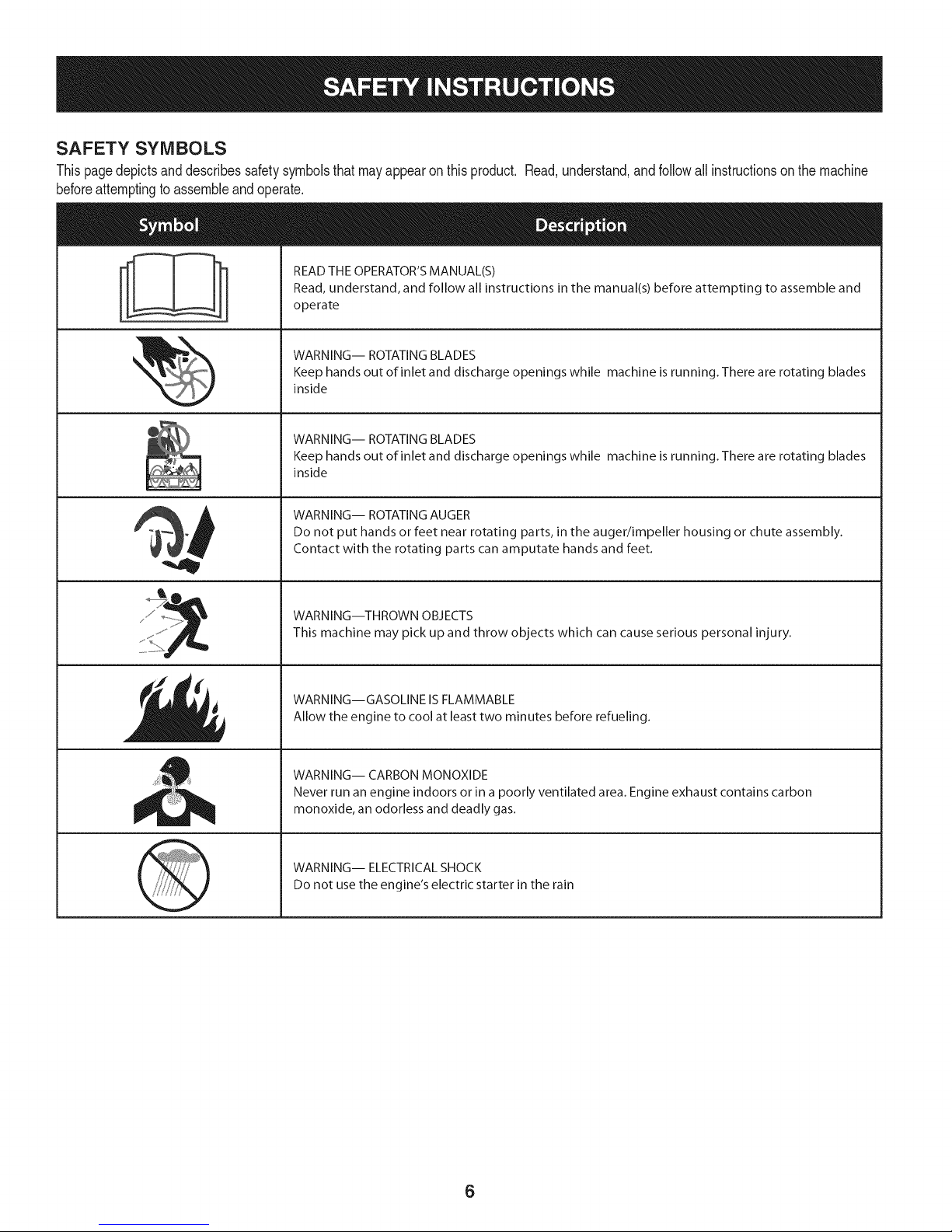
SAFETY SYMBOLS
Thispagedepictsanddescribessafetysymbolsthatmayappearonthisproduct. Read,understand,andfollowall instructionson themachine
beforeattemptingto assembleandoperate.
READ THE OPERATOR'S MANUAL(S)
i
. +
i
Read, understand, and follow all instructions in the manual(s) before attempting to assemble and
operate
WARNING-- ROTATING BLADES
Keep hands out of inlet and discharge openings while machine isrunning. There are rotating blades
inside
WARNING-- ROTATING BLADES
Keep hands out of inlet and discharge openings while machine is running. There are rotating blades
inside
WARNING-- ROTATING AUGER
Do not put hands or feet near rotating parts, in the auger/impeller housing or chute assembly.
Contact with the rotating parts can amputate hands and feet.
"JIp
WARNING--THROWN OBJECTS
This machine may pick up and throw objects which can cause serious personal injury.
WARNING--GASOLINE IS FLAMMABLE
Allow the engine to cool at least two minutes before refueling.
WARNING-- CARBON MONOXIDE
Never run an engine indoors or in a poorly ventilated area. Engine exhaust contains carbon
monoxide, an odorless and deadly gas+
WARNING-- ELECTRICAL SHOCK
Do not use the engine's electric starter in the rain
6
Page 7
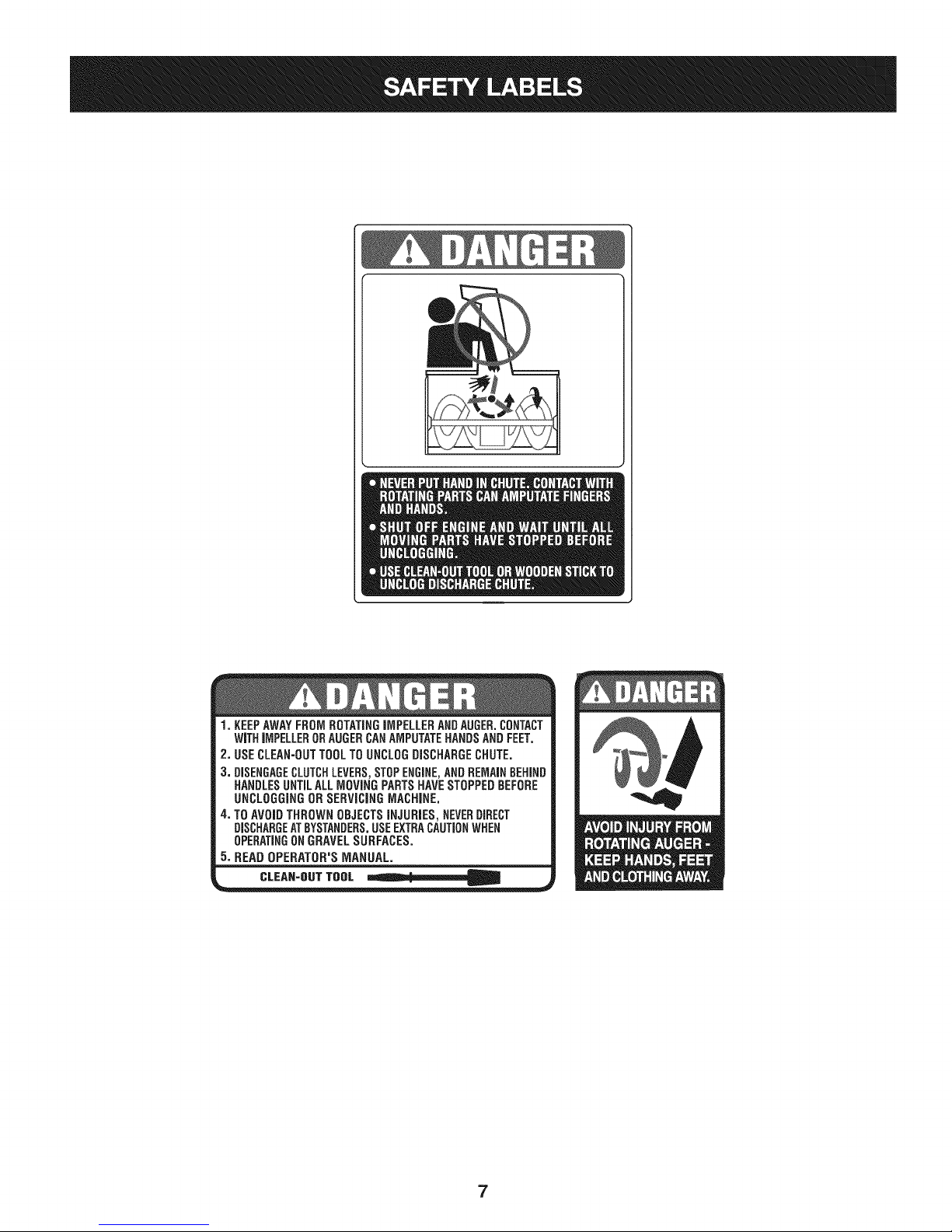
1.KEEPAWAYFROMROTATINGiMPELLERANDAUGER.CONTACT
WiTHiMPELLERORAUGERCANAMPUTATEHANDSANDFEET,
2, USECLEAN=OUTTOOLTOUNCLOGDISCHARGECHUTE.
3. DISENGAGECLUTCHLEVERS,STOPENGINE,ANDREMAINBEHIND
HANDLESUNTILALLMOVINGPARTSHAVESTOPPEDBEFORE
UNCLOGGINGORSERViCiNGMACHINE.
4. TOAVOIDTHROWNOBJECTSiNJURiES,NEVERDIRECT
DISCHARGEATBYSTANDERS.USEEXTRACAUTIONWHEN
OPERATINGONGRAVELSURFACES.
5.READOPERATOR'SMANUAL.
CLEAN-OUTTOOL
7
Page 8
iMPORTANT:Thisunitisshippedwiththeenginefullofoil.After
assembly,see page10forfuel andoildetails.
Removing From Carton
1. Cutthecornersof thecartonandlaythesidesflaton theground.
Removeall packinginserts.
2. Movethesnowthrowerout ofthecarton.
3. Makecertainthecartonhas beencompletelyemptiedbefore
discardingit.
DO NOTliftthe snowthrower bythechute handle.
Before Assembly
NOTE:Referenceto right,left, frontor rearof theunit isfromthe
operatingposition,facingforward,unlessotherwisestated.
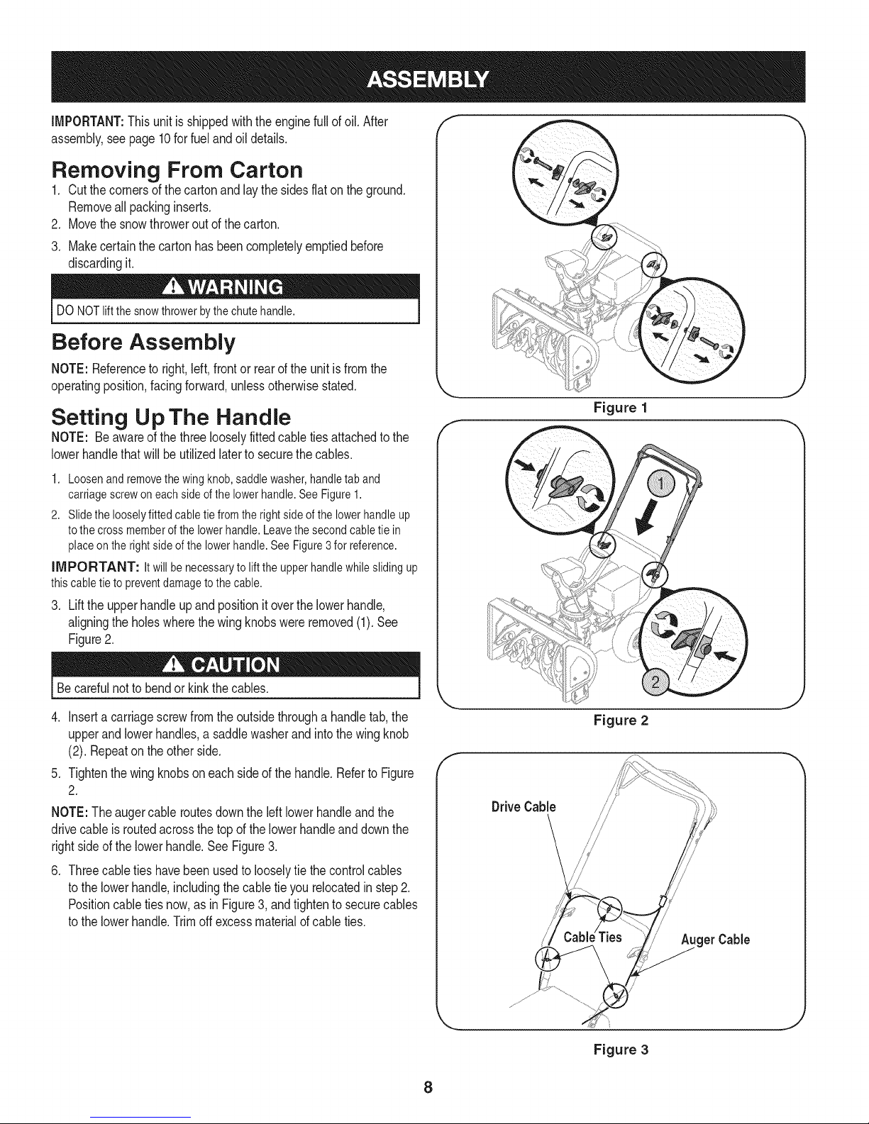
Setting Up The Handle
NOTE: Beawareofthethreelooselyfittedcabletiesattachedtothe
lowerhandlethatwill beutilizedlatertosecurethe cables.
1. Loosenandremovethewing knob,saddlewasher,handletab and
carriagescrewoneachsideofthe lowerhandle.SeeFigure1.
2. Slidethe looselyfittedcabletiefromthe rightsideofthe lowerhandleup
tothecross memberofthe lowerhandle.Leavethe secondcabletie in
placeonthe rightside ofthe lowerhandle.See Figure3 forreference.
iMPORTANT: Itwill benecessaryto liftthe upper handlewhileslidingup
thiscabletie to preventdamagetothecable.
3. Lift the upper handle up and position it over the lowerhandle,
aligning the holes where the wing knobs were removed (1). See
Figure 2.
f
Figure 1
Becarefulnotto bendor kinkthecables.
4. Inserta carriagescrewfromtheoutsidethrougha handletab,the
upperand lowerhandles,asaddlewasherandintothe wingknob
(2). Repeatonthe otherside.
5. Tightenthewing knobsoneachsideof thehandle.RefertoFigure
2.
NOTE:The augercableroutesdowntheleft lowerhandleandthe
drivecableisroutedacrossthetopof thelowerhandleanddownthe
rightside ofthe lowerhandle.SeeFigure3.
.
Threecabletieshavebeenusedtolooselytie thecontrolcables
tothe lowerhandle,includingthecabletie yourelocatedinstep2.
Positioncabletiesnow,as inFigure3, andtightentosecurecables
tothe lowerhandle.Trimoffexcessmaterialofcableties.
Figure 2
Drive Cable
/
get Cable
_js jj
J
Figure 3
8
Page 9
Skid Shoe
Thesnowthrowerskidshoesareadjustedupwardatthefactoryforshipping
purposes.Adjustthemdownward,ifdesired,priortooperatingthesnow
thrower.
Clean-Out Tool
Thechuteclean-outtoolisfastenedtothetopd theaugerhousingwitha
mountingclipandacabletieatthefactory.Cutthecabletiebeforeoperating
thesnowthrower.SeeFigure5.
It isnot recommendedthatyouoperatethissnowthrowerongravel
as it caneasilypickup andthrowloosegravel,causingpersonal
injuryordamagetothe snowthrowerand surroundingproperty.
• Forclosesnowremovalona smoothsurface,raiseskidshoes
higherontheaugerhousingtolowershaveplate.
• Whentheareatobeclearedisuneven,suchasa graveldriveway,
lowerskidshoeson theaugerhousingtoraisethe shaveplate.
NOTE:Ifyou choosetooperatethesnowthrowerona gravelsurface,
keepthe skidshoesin lowestpositionformaximumclearance
betweenthegroundandtheshaveplate.
Operatingasnowthrowerequippedwithsteelskidshoesmayresult
in damagetonaturalstonepaversurfaces(e.g.sandstone,blue-
stone,limestone). Forinformationonavailablepolymerskidshoes,
call 1-800-4MY-HOME.
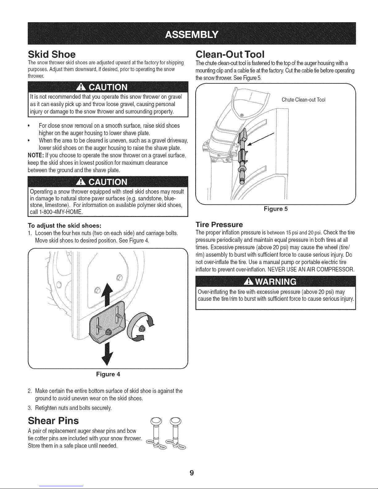
To adjust the skid shoes:
1. Loosenthefourhex nuts(twooneachside)andcarriagebolts.
Moveskidshoestodesiredposition.SeeFigure4.
/
/,
//
©
ChuteClean-outTool
Figure 5
Tire Pressure
Theproperinflationpressureisbetween15psiand20psi.Checkthe tire
pressureperiodicallyandmaintainequalpressureinbothtiresatall
times.Excessivepressure(above20 psi)maycausethe wheel(tire/
rim)assemblytoburstwithsufficientforceto causeseriousinjury.Do
notover-inflatethetire.Usea manualpumpor portableelectrictire
inflatorto preventover-inflation.NEVERUSEANAIRCOMPRESSOR.
Figure 4
2. Makecertaintheentirebottomsurfaceof skidshoeis againstthe
groundtoavoidunevenwearontheskidshoes.
3. Retightennutsandboltssecurely.
Shear Pins
A pairof replacementaugershearpinsandbow
tiecotterpinsare includedwithyoursnowthrower.
Storethemina safeplaceuntilneeded.
Over-inflatingthetirewithexcessivepressure(above20psi)may
causethetire/rimto burstwithsufficientforcetocauseseriousinjury.
9
Page 10
Fuel Recommendations
Useautomotivegasoline(unleadedor low leadedtominimizecombus-
tionchamberdeposits)witha minimumof87octane.Gasolinewith
upto 10%ethanolor 15%MTBE(MethylTertiaryButylEther)canbe
used.Neveruseanoil/gasolinemixtureor dirtygasoline.Avoidgetting
dirt,dust,or waterinthefueltank. DONOTuseE85gasoline.
* Refuelin awell-ventilatedareawiththe enginestopped.Donot
smokeorallowflamesorsparksintheareawheretheengineis
refueledorwheregasolineisstored.
* Do notoverfillthe fueltank.Afterrefueling,makesurethetank
capis closedproperlyandsecurely.
* Becarefulnot tospillfuelwhen refueling.Spilledfuelor fuelvapor
mayignite.Ifanyfuelisspilled,makesuretheareaisdry before
startingtheengine.
* Avoidrepeatedor prolongedcontactwithskinor breathingof
vapor.
Adding Fuel
Useextremecarewhenhandlinggasoline.Gasolineisextremely
flammableandthe vaporsareexplosive.Neverfuelthe machine
indoorsorwhiletheengineishotor running.Extinguishcigarettes,
cigars,pipesandothersourcesofignition.
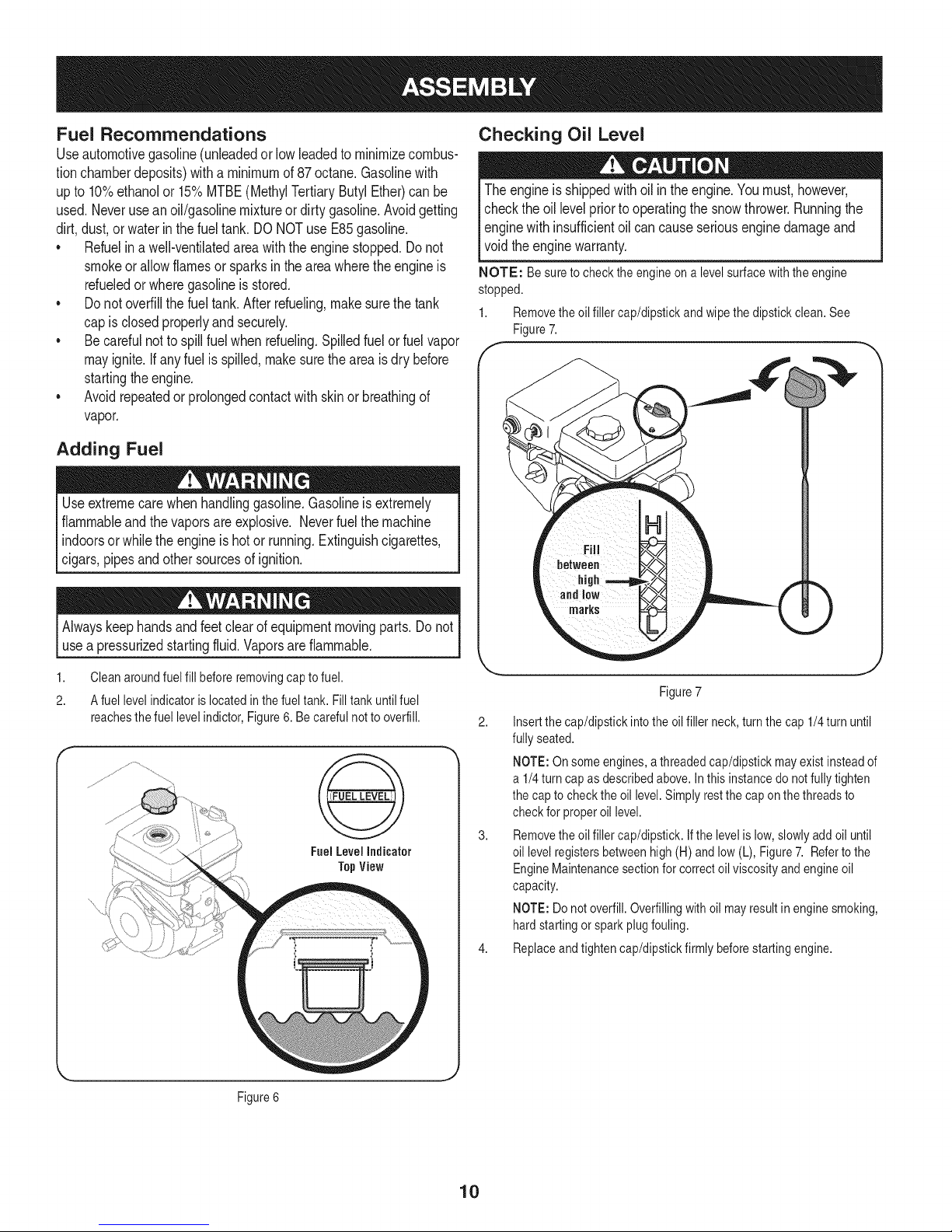
Checking Oil Level
Theengineis shippedwithoil in theengine.Youmust,however,
checkthe oil levelpriortooperatingthesnowthrower.Runningthe
enginewithinsufficientoilcancauseseriousenginedamageand
voidtheenginewarranty.
NOTE: Besuretocheckthe engineon a levelsurfacewiththe engine
stopped.
1. Removetheoil fillercap/dipstickand wipethe dipstickclean.See
Figure7.
f-
Alwayskeephandsandfeetclear ofequipmentmovingparts.Donot
usea pressurizedstartingfluid.Vaporsareflammable.
1. Cleanaroundfuel fillbeforeremovingcaptofuel.
2. A fuellevelindicatorislocatedinthefuel tank. Filltankuntil fuel
reachesthefuellevel indictor,Figure6. Becarefulnottooverfill.
FuelLevelIndicator
TopView
)
Figure7
2. Insertthe cap/dipstickintothe oilfillerneck,turnthecap 1/4turnuntil
fully seated.
NOTE:On someengines,a threadedcap/dipstickmayexistinsteadof
a 1/4turncapasdescribedabove.Inthis instancedo notfullytighten
the captochecktheoil level.Simplyrestthe cap onthe threadsto
checkfor properoil level.
3. Removetheoil fillercap/dipstick.Ifthe levelis low,slowlyadd oiluntil
oil levelregistersbetweenhigh(H)andlow(L), Figure7. Referto the
EngineMaintenancesectionforcorrectoil viscosityandengineoil
capacity.
NOTE:Do notoverfill.Overfillingwithoil mayresult inenginesmoking,
hardstartingorsparkplugfouling.
4. Replaceandtightencap/dipstickfirmly beforestartingengine.
Figure6
10
Page 11
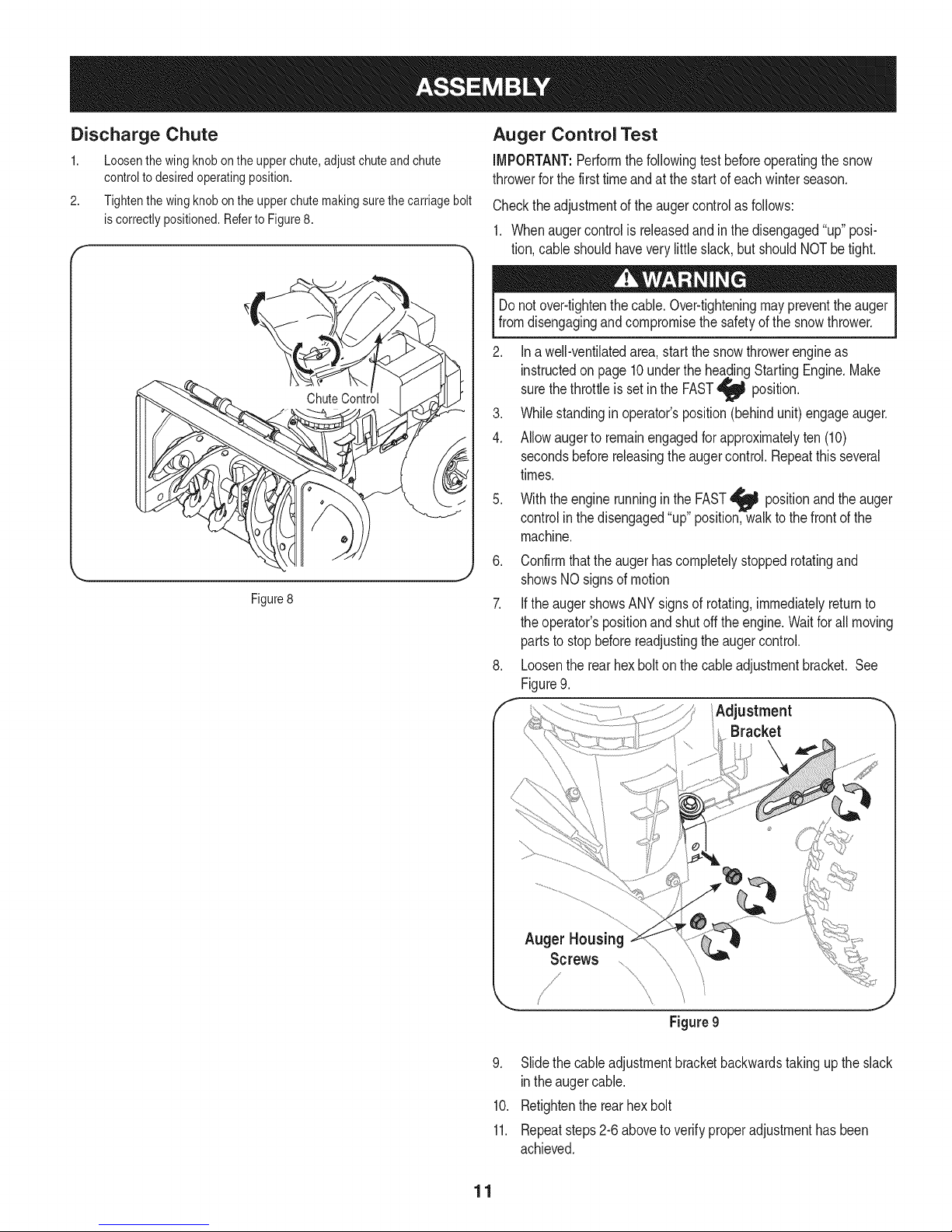
Discharge Chute
1. Loosenthewingknobontheupperchute,adjustchuteandchute
controltodesiredoperatingposition.
2. Tightenthewingknobontheupperchutemakingsurethecarriagebolt
iscorrectlypositioned.RefertoFigure8.
J
Figure8
Auger Control Test
iMPORTANT:Performthefollowingtest beforeoperatingthesnow
throwerforthe firsttimeandat thestartof eachwinterseason.
Checktheadjustmentof theaugercontrolasfollows:
1. Whenaugercontrolisreleasedandinthedisengaged"up" posi-
tion,cableshouldhaveverylittleslack,butshouldNOTbetight.
Donot over-tightenthecable.Over-tighteningmaypreventtheauger
fromdisengagingandcompromisethe safetyofthe snowthrower.
2. Inawell-ventilatedarea,startthe snowthrowerengineas
instructedon page10undertheheadingStartingEngine.Make
sure
thethrottleisset inthe FAST
3. Whilestandinginoperator'sposition(behindunit)engageauger.
4. Allowaugerto remainengagedforapproximatelyten(10)
secondsbeforereleasingthe augercontrol.Repeatthisseveral
times.
5. Withtheenginerunninginthe FAST_ positionandthe
controlinthedisengaged"up"position,walktothe frontofthe
machine.
6. Confirmthattheaugerhascompletelystoppedrotatingand
showsNOsignsofmotion
7. IftheaugershowsANYsignsof rotating,immediatelyreturnto
theoperator'spositionandshutofftheengine.Waitforallmoving
partsto stopbeforereadjustingtheaugercontrol.
8. Loosentherearhexbolton thecableadjustmentbracket.See
Figure9.
f Adjustment "
position.
auger
Bracket
Auger Housing
Screws
Figure9
9. Slidethecableadjustmentbracketbackwardstakinguptheslack
intheaugercable.
10. Retightentherearhexbolt
11. Repeatsteps2-6abovetoverifyproperadjustmenthasbeen
achieved.
11
Page 12
f
ChuteAssembly
Clean-out Tool
Auger
UpperChute
ShavePlate
\
UpperHandle
AugerControl Control
/f FuelCap
Muffler RecoilStarter
Throttle
Control
ChuteKnob
SkidShoe
Choke Button
Control
Drive
Handle
Handle
Oil Cap
ElectricStarter
OilDrain ElectricStarterOutlet )
,J
Befamiliarwithall thecontrolson thesnowthrowerandtheirproperoperation.Knowhowto stopthemachineanddisengagethemquickly.
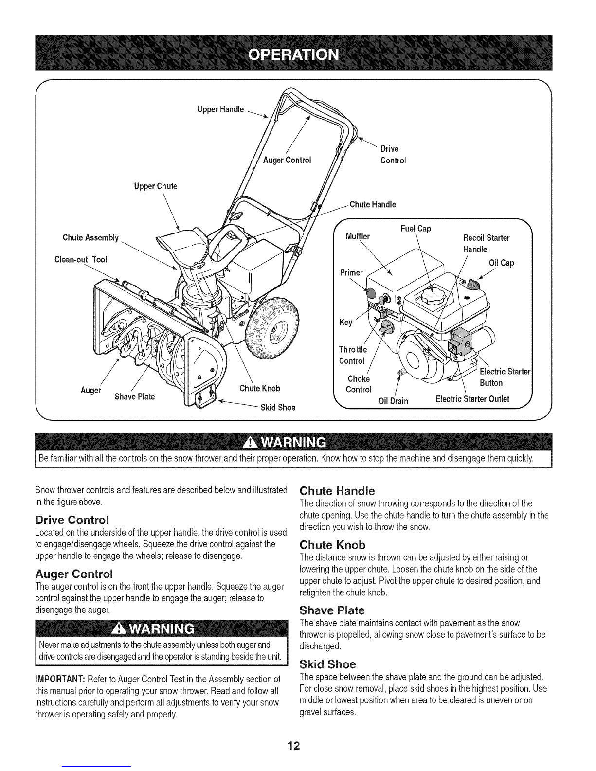
Snowthrowercontrolsandfeaturesaredescribedbelowandillustrated
inthefigureabove.
Drive Control
Locatedon theundersideofthe upperhandle,thedrivecontrolisused
toengage/disengagewheels.Squeezethedrivecontrolagainstthe
upperhandleto engagethewheels;releasetodisengage.
Auger Control
Theaugercontrolis onthefrontthe upperhandle.Squeezetheauger
controlagainsttheupperhandleto engagetheauger;releaseto
disengagethe auger.
Nevermakeadjustmentstothechuteassemblyunlessbothaugerand
drivecontrolsaredisengagedandtheoperatorisstandingbesidetheunit.
IMPORTANT:Referto AugerControlTestinthe Assemblysectionof
thismanualpriorto operatingyoursnowthrower.Readandfollowall
instructionscarefullyandperformall adjustmentsto verifyyoursnow
throwerisoperatingsafelyandproperly.
Chute Handle
Thedirectionof snowthrowingcorrespondsto thedirectionofthe
chuteopening.Usethechutehandletoturn thechuteassemblyinthe
directionyouwishto throwthesnow.
Chute Knob
Thedistancesnowisthrowncan beadjustedbyeither raisingor
loweringtheupperchute.Loosenthechuteknobonthesideofthe
upperchutetoadjust.Pivottheupperchuteto desiredposition,and
retightenthechuteknob.
Shave Plate
Theshaveplatemaintainscontactwithpavementasthesnow
throwerispropelled,allowingsnowcloseto pavement'ssurfacetobe
discharged.
Skid Shoe
Thespacebetweenthe shaveplateandthegroundcanbeadjusted.
Forclosesnowremoval,placeskidshoesin the highestposition.Use
middleor lowestpositionwhenareato beclearedisunevenoron
gravelsurfaces.
12
Page 13
Auger
Whenengaged,theaugerrotatesanddrawssnowintotheauger
housing.
Chute Assembly
Snowdrawnintotheaugerhousingisdischargedoutthechute
assembly.
Choke Control
Thechokecontrolaidsin startingtheengine.For
informationonchokeusage,seeStartingThe
Enginelaterin thissection.
Recoil Starter & Starter Handle
Thismotorisfittedwitha recoilactionpullstartand
a mittengriphandlefor easyaccesswhilewearingglovesormittens.
Key
Thekeyis a safetydevice.Itmustbefullyinserted _ ,,,,._
in orderforthe enginetostart.Removethekey
whenthe snowthrowerisnot inuse.
NOTE:Do notturn thekeyin anattemptto start
theengine.Doingso maycauseitto break.
Fe
Electric Starter Button
Pressingtheelectricstarterbuttonengagestheengine'selectric
starterwhenpluggedintoa 120Vpowersource.
Clean=Out Tool
Neveruseyour handstoclearacloggedchuteassembly.Shutoff
engineandremainbehindhandlesuntilallmovingpartshavestopped
[before usngthe ccan-outtoo to c earthechuteassemby.
Thechuteclean-outtool isconvenientlyfastenedtothe rearofthe
augerhousingwitha mountingclip.Shouldsnowand icebecome
lodgedinthechuteassemblyduringoperation,proceedasfollowsto
safelycleanthechuteassemblyandchuteopening:
1. Releaseboththe AugerControlandtheDriveControl.
2. Stoptheenginebyremovingthe key.
3. Removetheclean-outtoolfromthe clipwhichsecuresitto the
rearofthe augerhousing.
4. Usetheshovel-shapedendofthe clean-outtooltodislodgeand
scoopanysnowandice whichhasformedinand nearthechute
assembly.
5. Refastentheclean-outtoolto themountingclipon therearof
theaugerhousing,reinsertthekeyand startthe snowthrower's
engine.
6. Whilestandingintheoperator'sposition(behindthesnow
thrower),engagetheaugercontrolfora fewsecondstoclearany
remainingsnowand icefromthechuteassembly.
Before Starting Engine
Electric Starter Outlet
Requirestheuseof athree-prongoutdoorextensioncord(included)
anda 120Vpowersource/walloutlet.
Primer
Pressingtheprimerforcesfueldirectlyinto
engine'scarburetorto aid incold-weatherstarting, qk_/,..=_,,L.,_
Refertothe startinginstructionsin theOperation I
sectionof thismanualforproperprimerusage.The |
imagetothe rightcorrespondswiththe labelon the
engineidentifyingtheprimer.
Oil Fill
Removeoilcap toaddoil. Referto the Maintenance&Servicesection
forcheckingandaddingoil instructions.
Gasoline Cap
Removegascapto addfuel.Unitrunson regulargas.
NOTE:Thisunit mayincludea fuel plug,whichisonlyusedduring
assemblytokeepdirtanddebrisoutoffueltank. Discardthefuelplug
beforefillingthefuel tank.
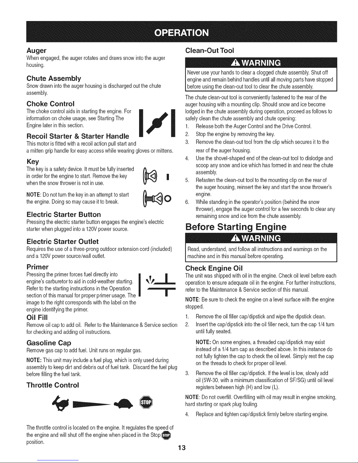
Throttle Control
Read,understand,andfollowallinstructionsandwarningsonthe
machineandinthis manualbeforeoperating.
Check Engine Oil
Theunitwas shippedwith oilin theengine.Checkoillevelbeforeeach
operationtoensureadequateoilintheengine.Forfurtherinstructions,
refertothe Maintenance& Servicesectionofthis manual.
NOTE:Besuretochecktheengineona levelsurfacewiththeengine
stopped.
1. Removetheoilfillercap/dipstickandwipe thedipstickclean.
2. Insertthecap/dipstickintotheoilfillerneck,turnthecap 1/4turn
untilfullyseated.
NOTE:Onsomeengines,a threadedcap/dipstickmayexist
insteadofa 1/4turncapasdescribedabove.Inthis instancedo
notfullytightenthe capto checktheoil level.Simplyrestthe cap
on thethreadstocheckfor properoil level.
Removethe oilfillercap/dipstick.Ifthe levelis low,slowlyadd
oil (5W-30,witha minimumclassificationofSF/SG)untiloil level
registersbetweenhigh(H) andlow(L).
NOTE:Donotoverfill.Overfillingwithoil mayresultin enginesmoking,
hardstartingor sparkplugfouling.
4. Replaceandtightencap/dipstickfirmlybeforestartingengine.
Thethrottlecontrolis locatedonthe engine.Itregulatesthespeedof
theengineandwill shutoff theenginewhenplacedintheStop__
position.
13
Page 14
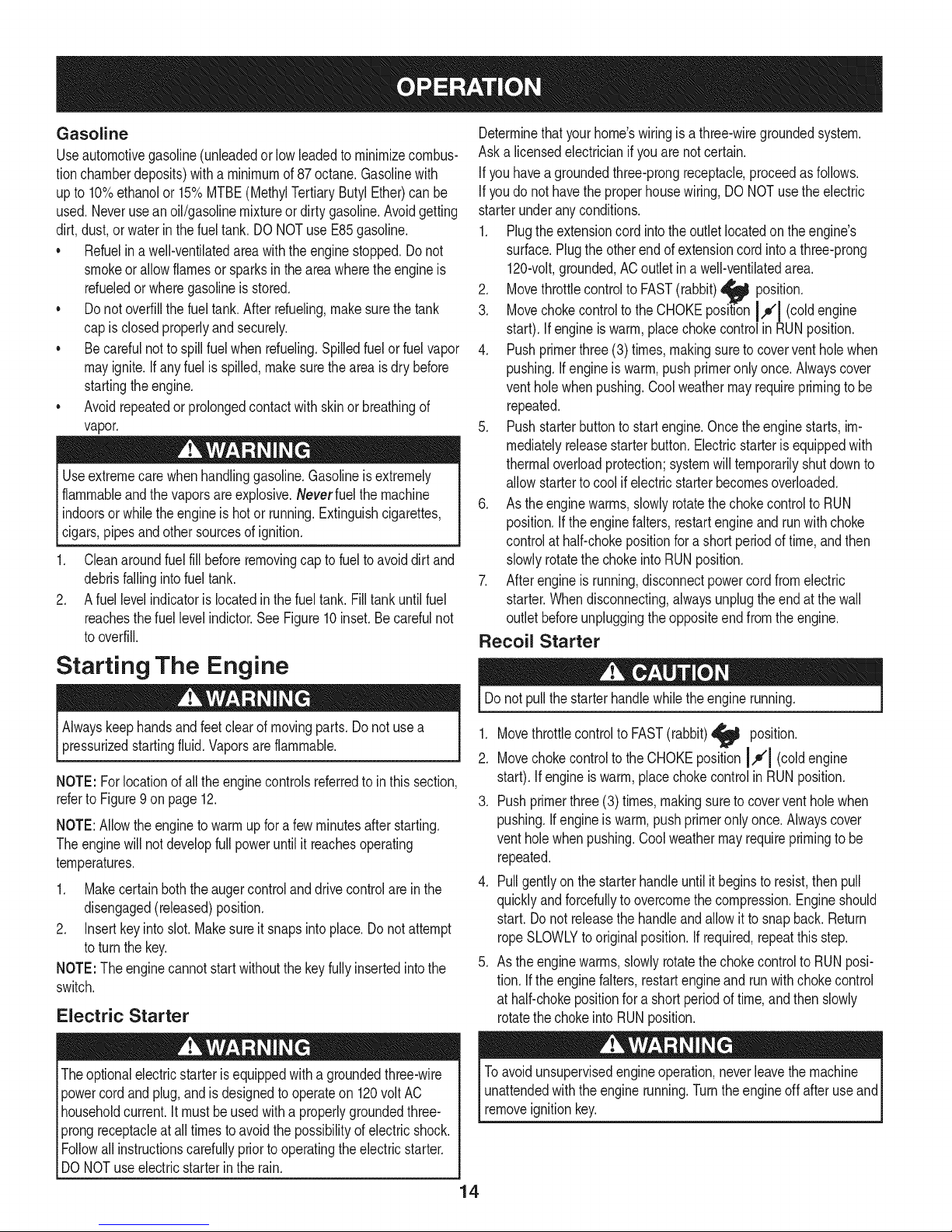
Gasoline
Useautomotivegasoline(unleadedor low leadedtominimizecombus-
tionchamberdeposits)witha minimumof87octane.Gasolinewith
upto 10%ethanolor 15%MTBE(MethylTertiaryButylEther)canbe
used.Neveruseanoil/gasolinemixtureor dirtygasoline.Avoidgetting
dirt,dust,or waterinthefueltank. DONOTuseE85gasoline.
• Refuelin awell-ventilatedareawiththeenginestopped.Donot
smokeorallowflamesorsparksintheareawheretheengineis
refueledorwheregasolineisstored.
• Donotoverfillthefuel tank.Afterrefueling,makesurethetank
capis closedproperlyandsecurely.
• Becarefulnotto spillfuel whenrefueling.Spilledfuelor fuelvapor
mayignite.Ifanyfuelisspilled,makesuretheareaisdry before
startingtheengine.
• Avoidrepeatedorprolongedcontactwithskinor breathingof
vapor.
Useextremecarewhenhandlinggasoline.Gasolineisextremely
flammableandthe vaporsareexplosive.Neverfuelthemachine
indoorsorwhiletheengineishot or running.Extinguishcigarettes,
cigars,pipesandothersourcesofignition.
1. Cleanaroundfuelfill beforeremovingcap tofueltoavoiddirtand
debrisfallingintofuel tank.
2. Afuellevelindicatorislocatedinthefueltank.Filltankuntilfuel
reachesthefuel levelindictor.SeeFigure10inset.Becarefulnot
tooverfill.
Determinethatyourhome'swiringisa three-wiregroundedsystem.
Aska licensedelectricianifyouarenotcertain.
Ifyouhavea groundedthree-prongreceptacle,proceedasfollows.
Ifyoudonot havethe properhousewiring,DONOTusetheelectric
starterunderanyconditions.
1. Plugtheextensioncordintotheoutletlocatedonthe engine's
surface.Plugtheotherendof extensioncordintoa three-prong
120-volt,grounded,ACoutletina well-ventilatedarea.
2. Movethrottlecontrolto FAST(rabbit)_ position.
3. MovechokecontroltotheCHOKEpositionI,,o'1(coldengine
start). Ifengineiswarm,placechokecontrolinRUNposition.
4. Pushprimerthree(3)times,makingsuretocoverventholewhen
pushing.If engineiswarm,pushprimeronlyonce.Alwayscover
ventholewhenpushing.Coolweathermayrequireprimingto be
repeated.
5. Pushstarterbuttonto startengine.Oncetheenginestarts,im-
mediatelyreleasestarterbutton.Electricstarterisequippedwith
thermaloverloadprotection;systemwilltemporarilyshutdownto
allowstartertocool ifelectricstarterbecomesoverloaded.
6. Astheenginewarms,slowlyrotatethechokecontroltoRUN
position.Iftheenginefalters,restartengineand runwith choke
controlat half-chokepositionfora shortperiodoftime,andthen
slowlyrotatethe chokeintoRUNposition.
7. Afterengineis running,disconnectpowercordfromelectric
starter.Whendisconnecting,alwaysunplugtheendatthe wall
outletbeforeunpluggingthe oppositeend fromtheengine.
Recoil Starter
Starting The Engine
Alwayskeephandsandfeetclear ofmovingparts.Donotusea
pressurizedstartingfluid.Vaporsareflammable.
NOTE:Forlocationofallthe enginecontrolsreferredto inthissection,
referto Figure9on page12.
NOTE:Allowtheengineto warmupfora fewminutesafterstarting.
Theenginewill notdevelopfullpoweruntilit reachesoperating
temperatures.
1. Makecertainboththe augercontrolanddrivecontrolareinthe
disengaged(released)position.
2. Insertkeyinto slot.Makesureit snapsintoplace.Do notattempt
toturnthekey.
NOTE:The enginecannotstartwithoutthekeyfullyinsertedintothe
switch.
Electric Starter
Theoptionalelectricstarterisequippedwitha groundedthree-wire
powercordandplug,andisdesignedtooperateon 120voltAC
householdcurrent.Itmustbeusedwitha properlygroundedthree-
prongreceptacleat alltimesto avoidthepossibilityofelectricshock.
Followall instructionscarefullypriortooperatingtheelectricstarter.
DONOTuse electricstarterintherain.
Donot pullthestarterhandlewhiletheenginerunning.
1. Movethrottlecontrolto FAST(rabbit)_j_ position.
2. MovechokecontroltotheCHOKEpositionI,,_'l (coldengine
start). Ifengineiswarm,placechokecontrolinRUNposition.
3. Pushprimerthree(3) times,makingsuretocoverventholewhen
pushing.If engineiswarm,pushprimeronlyonce.Alwayscover
ventholewhenpushing.Coolweathermayrequireprimingto be
repeated.
4. Pullgentlyonthestarterhandleuntilitbeginsto resist,thenpull
quicklyandforcefullytoovercomethecompression.Engineshould
start. Donot releasethehandleandallowitto snapback.Return
ropeSLOWLYto originalposition.Ifrequired,repeatthisstep.
5. Astheenginewarms,slowlyrotatethechokecontroltoRUNposi-
tion. Ifthe enginefalters,restartengineandrunwithchokecontrol
at half-chokepositionfora shortperiodoftime,andthenslowly
rotatethechokeintoRUNposition.
Toavoidunsupervisedengineoperation,neverleavethemachine
unattendedwiththeenginerunning.Turntheengineoffafteruseand
removeignitionkey.
4
Page 15
Stopping The Engine
Runenginefor a fewminutesbeforestoppingtohelpdryoff any
moistureonthe engine.
1. Movethrottlecontrolto STOP position.
2. Removethekey.Removingthekeywill reducethepossibilityof
unauthorizedstartingoftheenginewhileequipmentisnotin use.
Keepthekeyina safeplace.The enginecannotstartwithoutthe
key.
3. Wipeanymoistureawayfromthe controlsontheengine..
To Stop The Snow Thrower
1. Tostopthewheels,releasethedrivecontrol.
2. Tostopthrowingsnow,releasetheaugercontrol.
3. Tostopengine,movethrottlecontrollevertoOFF @ and pullout
thekey.Donot turnkey.
Thetemperatureofmufflerandthesurroundingareasmayexceed
1500F.Avoidtheseareas.
Using Snow Thrower to Clear
Snow
CAUTION:Checktheareatobe clearedforforeignobjects.Remove
foreignobjects,if any.
1. Starttheenginefollowingstartinginstructions.
2. Allowtheenginetowarmupfor a fewminutesasthe enginewillnot
developfullpoweruntilitreachesoperatingtemperature.
3. Rotatethechuteassemblytothe desireddirection,awayfrom
bystandersand/orbuildings.
4. Makingcertainno bystandersor obstaclesarein frontof theunit,
squeezetheaugercontrolcompletelyagainsttheupperhandleto
fullyengagetheauger.
5. Whiletheaugercontrolisengaged,squeezethedrivecontrol
completelyagainstthe upperhandleto engagethewheels.Donot
"feather"thedrivecontrol.
6. Asthesnowthrowerstartsto move,maintaina firmholdon the
handle,andguidethe snowthroweralongthepathtobe cleared.
7. Releasetheaugerand drivecontrolstostopthesnowthrowing
actionandforwardmotion.
NOTE:Yourunit isequippedwitha clutchinthe transmission.If the
wheelsstopturningwhiletryingtodischargelargevolumesofsnow,
immediatelydisengagethedrivecontroland allowtherotatingauger
todischargesnowfromthe housing.Reducetheclearingwidthand
continueoperation.
8. Oneachsucceedingpass,readjustthechuteassemblytothe
desiredpositionandslightlyoverlapthepreviouslyclearedpath.
Positioning Discharge Chute
Loosenthechuteknobandpivotupperchutetodesiredposition.Tighten
thechuteknobmakingsurethecarriageboltiscorrectlypositioned.
Rotatechutehandletodesiredoperatingposition.
Donot liftthe snowthroweratanytimebythe chutehandle.
Operating Tips
1. Formostdficientsnowremoval,removesnowimmediatelyafteritfalls.
2. Dischargesnowdownwindwheneverpossible.Slightlyoverlap
eachpreviouspath.
3. Settheskidshoes1/4"belowtheshaveplatefornormalusage.
Theskidshoesmaybeadjustedupwardforhard-packedsnow.
NOTE:It isnotrecommendedthatyouoperatethis snowthroweron
gravelas loosegravelcanbe easilypickedupand thrownbythe auger
causingpersonalinjuryand/ordamagetothe snowthrower.
4. Ifyouchooseto operatethesnowthrowerongravel,keepthe skid
shoeinthe lowestpositionformaximumclearancebetweenthe
groundandtheshaveplate.
5. Cleanthesnowthrowerthoroughlyaftereachuse.
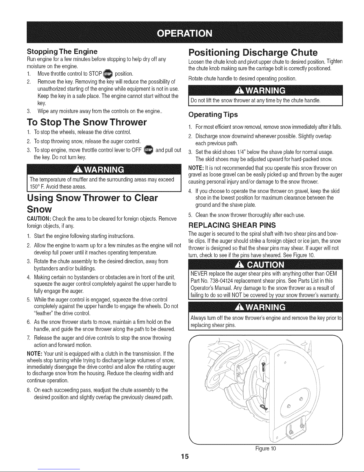
REPLACING SHEAR PINS
Theaugeris securedtothespiralshaftwithtwo shearpinsandbow-
tieclips. Iftheaugershouldstrikea foreignobjector icejam,thesnow
throwerisdesignedsothatthe shearpinsmayshear.Ifaugerwillnot
turn,checkto seeifthepins havesheared.SeeFigure10.
NEVERreplacetheaugershearpinswithanythingotherthanOEM
PartNo.738-04124replacementshearpins.SeePartsListinthis
Operator'sManual.Anydamagetothe snowthrowerasaresultof
failingto do sowill NOTbecoveredbyyoursnowthrower'swarranty.
Alwaysturnoffthesnowthrower'sengineand removethekeypriorto
replacingshearpins.
J
Figure10
15
Page 16
Beforeservicing,repairing,lubricatingorinspecting,disengageall
controlsandstopengine.Waituntilallmovingpartshavecometoa
completestop.Removethekeytopreventunintendedstarting.Always
wearsafetyglassesduringoperationorwhileperforminganyadjust-
mentsorrepairs.
Maintenance Schedule
EachUseandevery5
hours
1st5 hours
Annuallyor25hours
Annuallyor50hours
Annuallyor100hours
BeforeStorage 1. Fuelsystem 1.
1. Engineoillevel
2. Looseormissinghardware
3. Unitandengine.
1. Engineoil
1. Sparkplug
2. Controllinkagesand pivots
3. Wheels
4. GearshaftandAugershaft
1. Engineoil
1. Sparkplug
ENGINE MAINTENANCE
Checking Engine Oil
1. Check
2. Tightenor replace
3. Clean
1. Change
1. Check
2. Lubewithlightoil
3. Lubewithmultipurposeautogrease
4. Lubewithlightoil
1. Change
1. Clean,adjustgap,or replaceif
Followthemaintenanceschedulegivenbelow.Thischartdescribes
serviceguidelinesonly.UsetheServiceLogcolumntokeeptrack
ofcompletedmaintenancetasks.TolocatethenearestSears
ServiceCenteror to scheduleservice,simplycontactSearsat
1-800-4-MY-HOME®.
= =
necessary
Runengineuntilit stopsfromlack
offuel
f
Beforelubricating,repairing,or inspecting,disengageall controls
Iandstopengine.Waituntilall movingpartshavecometo a complete
_stop.
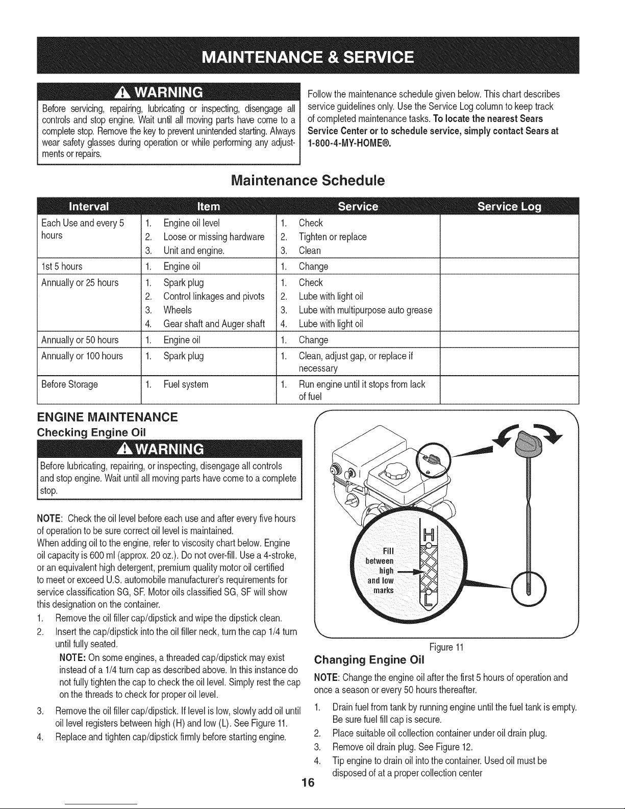
NOTE: Checktheoil levelbeforeeachuseandaftereveryfivehours
ofoperationtobesurecorrectoil levelismaintained.
Whenaddingoilto theengine,referto viscositychart below.Engine
oilcapacityis 600ml (approx.20 oz.).Donot over-fill.Usea4-stroke,
oran equivalenthighdetergent,premiumqualitymotoroilcertified
tomeetorexceedU.S.automobilemanufacturer'srequirementsfor
serviceclassificationSG, SRMotoroilsclassifiedSG,SFwillshow
thisdesignationonthecontainer.
1. Removetheoil fillercap/dipstickandwipethedipstickclean.
2. Insertthe cap/dipstickintotheoilfillerneck,turnthecap 1/4turn
untilfullyseated.
NOTE:On someengines,athreadedcap/dipstickmayexist
insteadofa 1/4turncap asdescribedabove.Inthisinstancedo
notfullytightenthe capto checktheoil level.Simplyrestthecap
onthethreadsto checkfor properoil level.
3. Removetheoil fillercap/dipstick.Iflevelislow,slowlyaddoiluntil
oil levelregistersbetweenhigh(H)andlow (L).SeeFigure11.
4. Replaceandtightencap/dipstickfirmlybeforestartingengine.
j
Figure11
Changing Engine Oil
NOTE:Changetheengineoil afterthefirst 5 hoursofoperationand
oncea seasonorevery50 hoursthereafter.
1. Drainfuelfromtankbyrunningengineuntilthefuel tankisempty.
Besurefuel fillcapis secure.
2. Placesuitableoilcollectioncontainerunderoil drainplug.
3. Removeoildrainplug.SeeFigure12.
4. Tipenginetodrainoil intothecontainer.Usedoilmustbe
disposedofat a propercollectioncenter
16
Page 17
Usedoil isa hazardouswasteproduct.Disposeof usedoil properly.
Donotdiscardwith householdwaste.Checkwithyourlocalauthori-
tiesor SearsServiceCenterfor safedisposal/recyclingfacilities.
.
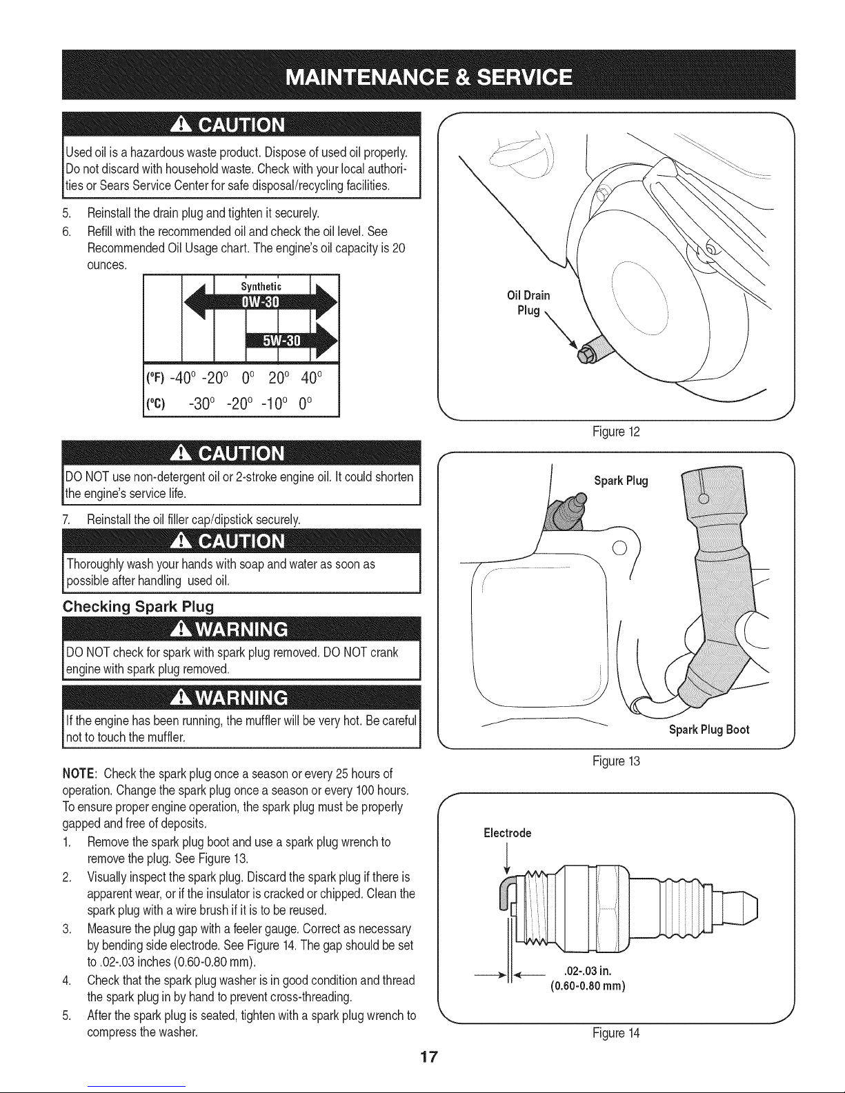
Reinstallthedrainplugandtightenit securely.
6.
Refillwiththerecommendedoil andcheckthe oil level.See
RecommendedOilUsagechart.Theengine'soilcapacityis 20
ounces.
i i
(%-400 -200 0o 200 400
f
Oil Drain
Plug
("c) -30° -20° -10° 0°
DONOTuse non-detergentoilor 2-strokeengineoil.Itcouldshorten
theengine'sservicelife.
7. Reinstalltheoilfillercap/dipsticksecurely.
Thoroughlywashyourhandswithsoapandwaterassoonas
possibleafterhandling usedoil.
Checking Spark Plug
DONOTcheckforsparkwithsparkplugremoved.DONOTcrank
enginewithsparkplugremoved.
Iftheenginehasbeenrunning,themufflerwillbevery hot.Becareful
notto touchthemuffler.
NOTE: Checkthesparkplugoncea seasonorevery25hoursof
operation.Changethesparkplugoncea seasonorevery100hours.
Toensureproperengineoperation,thesparkplugmustbeproperly
gappedandfreeof deposits.
1. Removethesparkplugbootanduse a sparkplugwrenchto
removetheplug.See Figure13.
2. Visuallyinspectthesparkplug.Discardthesparkplugif thereis
apparentwear,orif the insulatoriscrackedorchipped.Cleanthe
sparkplugwitha wirebrush ifitis to be reused.
3. Measurethepluggapwitha feelergauge.Correctasnecessary
bybendingsideelectrode.SeeFigure14.Thegapshouldbeset
to.02-.03inches(0.60-0.80ram).
4. Checkthatthe sparkplugwasheris ingoodconditionandthread
thesparkplugin by handto preventcross-threading.
5. Afterthesparkplugis seated,tightenwithasparkplugwrenchto
compressthewasher.
.J
Figure12
SparkPlug
SparkPlug Boot
Figure13
Electrode
___,. ,___ .02-.03in.
(0.60-0.80ram)
Figure14
17
Page 18

NOTE:Wheninstallinga newsparkplug,tighten1/2-turnafterthe
sparkplugseatsto compressthewasher.Whenreinstallinga used
sparkplug,tighten1/81to 1/41turnafterthesparkplugseatsto
compressthewasher.GeneralRecommendations
1. Alwaysobservesafetyruleswhenperforminganymaintenance.
2. Thewarrantyon thissnowthrowerdoesnotcoveritemsthathave
beensubjectedto operatorabuseor negligence.Toreceivefull
valuefromthe warranty,operatormustmaintainthesnowthrower
asinstructedinthismanual.
3. Periodicallycheckallfastenersandhardwaretomakesurethese
aretight.
Replacing the Shave Plate and
Skid Shoes
Theshaveplateand skidshoesonthebottomofthe snowthrowerare
subjecttowear.Theseshouldbecheckedperiodicallyandreplaced
whennecessary
1. Toreplace,removetwocarriageboltsandnutssecuringeachskidshoe
totheaugerhousing.SeeFigure15.
f
ShearPin
CotterPin
SkidShoe
l
Carriage Bolt
ShavePlate /
LockNut
CarriageBolt /_
Figure15
/
LockNut
J
Lubrication
Fora viewof the lubricationpointsonthesnowthrower,seeFigure16.
1. Lubricatepivotpointsontheaugercontrolanddrivecontrolwitha
lightengineoilonce a season.
2. Lubricatetheaugeridlerbracketwitha lightengineoilonceaseason.
Figure16
Engine
Listedbelowaregeneralrecommendationsaboutmaintainingyour
snowthrowerengine.
1. Beforeoperatingsnowthrower,checktheoil level.
2. Changeengineoilafterfirst fivehoursofoperationandevery50
hoursthereafter.
3. Cleansparkplugandresetthe electrodegapto 0.030"at least
oncea seasonorevery100hoursofoperation;replaceevery200
hoursof operation.
.
Reassemblenewskidshoeswithhardwarejustremoved.Makesurethe
skidshoesareadjustedtobelevel.
3.
Toremoveshaveplate:Removebothskidshoesandhardware
includingcarriageboltsandnutswhichattachshaveplatetothe
snowthrowerhousing.Forlocationofshaveplate,seeFigure15.
.
Reassemblenewshaveplate,makingsureheadsofthecarriagebolts
aretotheinsideofthehousing.Reinstallskidshoes.Tightensecurely.
Servicing Auger
Theaugeris securedto thespiralshaftwithfourshearpinsandcotter
pins.Ifyouhit a foreignobjectoricejam,thesnowthrowerisdesigned
sothatthe pinsmayshear.Referto Figure15.
Iftheaugerdoesnotturn,check ifthe pinshavesheared.Replace,if
needed,withpropershearpins.Refertothe PartsListinthis manual
forthecorrectpart number.
IMPORTANT:NEVERreplacetheaugershearpinswithstandardpins
orfasteners.Anydamagetotheaugergearboxorothercomponents,
asa resultof doingso,willNOTbe coveredbyyoursnowthrower's
warranty.
18
Page 19

Check V-Belts
Followinstructionsbelowtocheckconditionofdrivebeltsevery50
hoursof operation.
1. Removetheplasticbeltcoveronthefrontoftheengineby
removingtheself-tappingscrewandpressingtheplastictabsto
releasethebeltcover.
2. Visuallyinspectforfrayed,cracked,orexcessivelyworn outbelts.
Replace,ifnecessary,andfollowinstructionsbelow.
Replacing Belts
NOTE:Therearetwobeltson thissnowthrower:anaugerbelt and
drivebelt.It isrecommendedthatbothbeltsbereplacedatthesame
time.
1. Removethesparkplugwirefromsparkplugandgrounditagainst
theengineto preventaccidentalstarting.
2. Runthe engineuntilthefueltankisdry topreventgasolineleakage
whenreplacingbelts.
Performbeltmaintenanceoutdoorsas somegasmaypossiblyleak
fromthecarburetor.
3. Removetheself-tappingscrewshownin Figure17,andpressthe
plastictabsto releasethebeltcover.Pullthebelt coverupand out
fromaroundtheengineandchuteassembly.Setitasideandsave.
Auger Belt
iMPORTANT:Becausegascouldleakfromthecarburetoratthis
point,theengineshouldhavebeenrununtil thefuel tankwasdry,as
previouslyinstructed.
1. Tipthesnowthrowerupandforwardsothat it restsontheauger
housing. Removethe beltkeeperascalledout inFigure19.Return
thesnowthrowertoitsuprightpositiontocompletethefollowing
steps.
2. Slipthefrontaugerbeltoffof theenginepulley,pushingitforward
and rollinginoff ofthepulley.SeeFigure18.
Idler Bracket
Figure17
Figure18
Squeezethe augercontrolhandleto releasetheaugerbrake,
whichisthe tabthatholdsthebeltontotheaugerpulley.Remove
thebelt.
4. Replacewithnewbeltafterreplacingthedrivebelt.
19
Page 20

Drive Belt
NOTE:Replacethedrivebelt beforereassemblingthenewaugerbelt.
1.Tip thesnowthrowerupandforwardsothat itrestson theauger
housing.
IMPORTANT:BecauseGascouldleakfromthecarburetoratthis
point,theengineshouldhavebeenrununtilthefuel tankwasdry,as
previouslyinstructed.
2.Removethespringthatconnectsthetransmissionto abolt onthe
engineframe.SeeFigure19.
NOTE:Itmaybeeasiertofirst removetheflangelocknut,thenuse
needle-nosedplierstofirmlygripspringandremovefrombolt.
F
Spring
Adjusting The Auger Cable
RefertotheAssemblysectionforinstructionson adjustingtheauger
controlcable.
........ _'*'_:" ...............DriveBelt
BeltKeeper
Figure19
3. Pivotthetransmissionforwardtoreleasepressureon thedrivebelt.
Removebeltfromtransmissionpulley.
4. Removethedrivebelt fromaroundtheenginepulley,andaway
fromtheunit.
5. Placethe newdrivebeltintothe grooveonthe enginepulley.See
Figure18.
6. Tiltthetransmissionforwardandpositionthedrivebeltontothe
transmissionpulley.
7. Reconnectthespringto theboltontheengineframeandsecure
thetransmission.Reinstalltheflangelocknut.
8. Installnewaugerbelt.
9. Reassemblethebeltcoveronthesnowthrower.
10.Reassemblethebeltkeepertothehousing.
2O
Page 21

Ifthe snowthrowerwillnotbe usedfor30 daysor longer,orifit istheendofthesnowseasonwhenthelastpossibilityof snowisgone,the
equipmentneedstobestoredproperly.Followstorageinstructionsbelowtoensuretopperformancefromthe snowthrowerformanymoreyears.
PREPARING ENGINE
Enginesstoredover30daysneedtobedrainedof fuelto prevent
deteriorationandgumfromforminginfuel systemoronessential
carburetorparts.If thegasolineinyourenginedeterioratesduring
storage,youmayneedto havethecarburetor,andotherfuel system
components,servicedor replaced.
1. Removeallfuel fromtank byrunningengineuntilit stops.Donot
attempttopourfuel fromtheengine.
2. Changetheengineoil.
3. Removesparkplugandpourapproximately1oz.(30 rnl)ofclean
engineoil intothe cylinder.Pullthe recoilstarterseveraltimesto
distributetheoil,and reinstallthesparkplug.
4. Cleandebrisfromaroundengine,andunder,around,andbehind
muffler.Applya lightfilmofoilon anyareasthatare susceptible
torust.
• Storeina clean,dry andwellventilatedareaawayfromanyap-
pliancethatoperateswithaflameor pilotlight,suchasa furnace,
waterheater,or clothesdryer.Avoidanyareawitha spark
producingelectricmotor,orwherepowertoolsareoperated.
Neverstoresnowthrowerwithfuelintank indoorsor inpoorlyventi-
latedareas,wherefuelfumesmayreachanopenflame,sparkor pilol
lightas ona furnace,waterheater,clothesdryerorgas appliance.
PREPARING SNOW THROWER
Whenstoringthe snowthrowerin anunventilatedormetalstor-
age shed,careshouldbetakentorustprooftheequipment.Using
a lightoilor silicone,coattheequipment,especiallyanychains,
springs,bearingsandcables.
• Removealldirt fromexteriorof engineandequipment.
• Followlubricationrecommendations.
• Storeequipmentina clean,dry area.
• If possible,avoidstorageareaswithhighhumidity.
• Keeptheenginelevelin storage.Tiltingcancausefueloroil
leakage.
21
Page 22

Beforeperforminganytypeofmaintenance/service,disengageall
controlsandstoptheengine.Waituntilallmovingpartshavecometoa
completestop.Removethekeytopreventunintendedstarting.Always
wearsafetyglassesduringoperationorwhileperforminganyadjustments
orrepairs.
Thissectionaddresses minor serviceissues.Tolocate the near-
est SearsService Centerorto scheduleservice,simplycontact
Searsat 1-800-4-MY-HOME®.
Enginefailsto start
1. Chokecontrolnotin Chokeposition.
2. Sparkplugwiredisconnected.
3. Faultysparkplug.
4. Fueltankemptyor stalefuel.
5. Enginenotprimed.
6. Safetykeynot inserted.
7. Extensioncordnotconnected(whenusing
electricstart button)
Enginerunningerratically/
inconsistentRPM(huntingor
surging)
Engineoverheats
Excessivevibration
.
Enginerunningonchoke. 1. Movechokeleverto RUNposition.
2.
Fuellineblocked,or stalefuel. 2. Cleanfuel lineandfilltankwithfresh,cleangasoline.
3.
Wateror dirtinfuel system. 3. Runengineuntilit stops.Refillwithfreshfuel.
4.
Carburetoroutof adjustment. 4. Contacta SearsServiceCenter.
5.
Over-governedengine 5. Contacta SearsServiceCenter.
1.
Carburetornotadjustedproperly. 1. ContactyourSearsParts& RepairCenter.
1.
Loosepartsordamagedauger. 1. Stopengineimmediatelyanddisconnectsparkplug
Lossof power 1. Sparkplugwireloose.
2. Gascap ventholeplugged.
Unitfailsto propelitself 1. Drivecablein needof adjustment.
2. Drivebeltlooseordamaged.
Unitfailstodischargesnow 1. Chuteassemblyclogged.
2. Foreignobjectlodgedinauger.
.
Augercableinneedof adjustment. 3. Adjustaugercontrolcable.RefertoAssembly
4.
Augerbeltlooseor damaged. 4. Replaceaugerbelt.Referto Serviceand Mainte-
5.
Shearpin(s)sheared. 5. Replacewith newshearpin(s).
1. MovechokecontroltoChokeposition.
2. Connectwireto sparkplug.
3. Clean,adjustgap,or replace.
4. Filltankwithclean,freshgasoline.
5. Primeengineasinstructedin theOperationSection.
6. Insertkeyfullyintothe switch.
7. Connectoneendof theextensioncordtotheelectric
starteroutletandthe otherendto a three-prong
120-volt,grounded,ACoutlet.
wire.Tightenall boltsandnuts.If vibrationcontinues,
haveunit servicedbya SearsParts&RepairCenter.
1. Connectandtightensparkplugwire.
2. Removeiceandsnowfromgascap.Becertainvent
holeisclear.
1. Adjustdrivecontrolcable.Referto Serviceand
Maintenancesection.
2. Replacedrivebelt.RefertoService&Maint.section.
1. Stopengineimmediatelyanddisconnectsparkplug
wire.Cleanchuteassemblyandinsideofauger
housingwithclean-outtoolor a stick.
2. Stopengineimmediatelyanddisconnectsparkplug
wire.Removeobjectfromaugerwithclean-outtool
or a stick.
section.
nancesection.
NEED MORE HELP?
o Find this and a[[ your other product manuals online.
o 6et answers from our team of home experts.
o 6et a personalized maintenance plan for your home,
o Find information and tools to help with home projects.
22
Page 23

Craftsman Snow Thrower Model 247.88779
777S32636
777X43688
"lVnNV_ S,UOIVU3dOQV3U"g
"S33VdUnS13AVU9NO_NilVU3dO
N3HMNOJlnV3VHIX33Sn"SU30NVlSA8lV 39HVHOSlO
13_UIGH3A3N'S31UgrNI$133r80 NMOUH1QIOAVOL"_
"3NiHOVW9NIOIAU3SHO9NI9903ON9
3U0:138g:IddOLS3AVHSLUVdONIA0_ITIV'IILNR$3"IQNVH
QNIH_8NiVW3tJONV'3NION]dOlS'SEFIA:FIH31R13_gVON3SJQ"_
"3/RHO39UVHOSIO9013NnO1qO01/OO'NV3lO3Sll "Z
"IBBdQNVSONVHBlVlnd_VNV3UBOnVUOU]ll]dBlHIIAA
IOVINO0"U]OflVONVUB]13d_l 9NIIVIOUWOU__VMVd]B_"L
777S32236 777123249
........................eeNOT...................
USEE85 ORFUEL
CONTAININGMORE
THAN10% ETHANOL
777122164
J
i/
777D12657
777i22138
777Dl1429
23
777D12682
Page 24

Craftsman Snow Thrower IViodel 247.88779
\
/
24
Page 25

Craftsman Snow Thrower IViodel 247.88779
iiiiii!ii!ii i !i !ililililiiiiiiii!iiiiiiii!!ii i i!!i!ii! ¸i ili !ii !ii i iiiiiiiiiiiiii!ii!ii!i!!!!!!!!!!!!!!!!!!!!!!!!!!!!!!!!!!!!!!! ii i iii!iii!iiiiiiii i iiiiiiiiiiiiiiiiii ii ii ii ii ii ii ii ii ii ii ii iiiii ii i!!!i!! ! ! ! ! iii ! !i i ! ! !i i! ! !i i i iiii i i i iiiiiiiiiiiiiiiiiiiiiiiiiiiiiiiiiiiiiiiiiiiiiiiiiiiiiiiiiiiiiiiiiiiiiiiiiiiiiiiiiiiiiiiiiiiiiiiiiiiiiiiiiiiiiiiiiiiiiiiiiiiiiiiiiiiiiiiiiiiiiiiiii!i i i
iiiiiiiiiiiiiiili!:!ili! i i!i!iiii!!iiiiiiii!i!!!iiiiiiii!iiiiiiii!i!i!i_!_!!_!i_!__i__i__i_!_!!!_!___i_!_i_i_i_i!i_!_!_!_i_!_!_!_!_!_!_!_!_!_!_!_!_i_i_i_!_i_i_i!__!_i_i__!!___i!!ii_i!i!i!_!_!___!_!_!_i_ii_i!_i!_i______!___!i_i!_!i!i___!_!!!!!_i!ii!!ii___i__!__i!_!_i_i_i_i!ii__!___!_!__i!_i__i_ii_!_i!i!!ii!!ii!!iiiiiii!ii!!ii!!i!iiiiii!iiiiiiii!iiiiiiiiiiiiii!!ii!!iiii__i_i_!_i_i_i!!_!!!_!!i!i!iiiii!iiii!i!iii!i!iiiiii!ii!!ii!!i!iiiiii!ii!!ii!!i!iiiiii!ii!!ii!!i!iiiiii!ii!!ii!!i!iiiiii!ii!!ii!!i!iiiiii!ii!!ii!!i!iiiiii!ii!!ii!!i!iiiiii!ii!!ii!!i!iiiiii!ii!!ii!!i!iiiiii!ii!!ii!!i!iiiiii!ii!!ii!!i!iiiiii!ii!!ii!!i!iiiiii!ii!!ii!!i!iiiiii!ii!!ii!!i!iiiiii!ii!!ii!!i!iiiiii!ii!!ii!!i!iiiiii!ii!!ii!!i!iiiiii!ii!!ii!!i!iiiiii!ii!!ii!!i!iiiiii!ii!!ii!!i!iiiiii!ii!!ii!!i!iiiiii!ii!!ii!!i!iiiiii!ii!!ii!!i!iiiiii!ii!!ii!i!_i_
1 984-04037 ChuteAssembly 25
2 710-04071 CarriageBolt5/16-18x1.0" 26
3 710-0451 CarriageBolt5/16-18 27
4 710-0260A CarriageBolt5/16-18x.62 28
5 720-04072AA WingKnob5/16-18 29
6 731-04388A ChuteHandle 30 941-0309
7 731-04426A UpperChute 31 950-04191
8 936-0267 FiatWasher.385x .87x .06 32 684-04358
9 931-04127 LowerChute 33 784-0434-0637
10 931-04353 ChuteRing 34 790-00075
11 931-2636A ChuteAdapter5" Dia. 35 918-04292B
12 932-04111 ChuteAdjustmentSpring 36 684-04113A-0637
13 712-04064 FlangeLockNut1/4-20 37 684-04114A-0637
14 931-2643 Clean-outTool 38 684-04166A-4044
15 731-2635 Clean-outToolMount 39 714-04040
16 725-0157 CableTie 40 731-04870
17 710-0134 CarriageScrew1/4-20x 0.62" 41 936-0351
18 710-0520 HexBolt3/8-16x 1.50" 42 738-04124A
19 710-04484 ABScrew5/16-18x .750 43 741-0493A
20 712-04063 FlangeLockNut,5/16-18 44 790-00087A-0637
21 712-04065 FlangeLockNut,3/8-16 45 790-00117-0637
22 750-04852 ShoulderSpacer 46 784-5580-4044
23 715-04020 Spiral Pin 47 710-04606A
24 926-04012 PushOnNut 48 929-0071A
731-04218B Impeller
932-0611 ExtensionSpring
736-0174 WaveWasher
938-0281 ShoulderScrew3/8-16
941-0245 Hex FlangeBearing
BallBearing
Spacer
FlatIdler
AugerIdlerBracket
BearingHousing
AugerGearboxAssembly
AugerAssembly- LH
AugerAssembly- RH
AugerHousing,22"
BowTieCotterPin72
Spacer,1.25x.75x 1.00
FlatWasher
ShearPin,.25x 1.50
FlangeBushing
Hex BearingHousing
ShavePlate2.25x21.66LG
SkidShoe
Belt Keeper
ExtensionCord
25
Page 26

Craftsman Snow Thrower Model 247.88779
26
Page 27

Craftsman Snow Thrower IViodel 247.88779
1 _710-0572 _ CarriageScrew5/16-18x 2.25
2 710-0605 Mach.Screw1/4-20x 1.825
3 710-04484 Screw5/16-18x.75
4 712-04064 FlangeLockNut 1/4-20
5 720-04072A WingKnob5/16-18
6 725-0157 CableTie
7 946-04642 DriveCable
8 946-04640 AugerCable
9 747-04394A-0637 AugerControl
10 747-04405-0637 DriveControl
11 749-04147 LowerHandle
12 749-04495-0637 UpperHandle
13 990-00053 HandleTab
14 918-04296B TransmissionAssembly
15 710-0809 TT Screw 1/4-20x 1.25
16 710-1652 Screw1/4-20x .625
17 711-1364 Clevis Pin
18 914-0115 Cotter Pin1/8x 1.0
19 714-04040 BowTieCotterPin72
20 915-0249 Roll Pin
21 717-04066A Pinion14T
22 917-04073A Gear70T
23 932-0429A ExtensionSpring
24 936-0192 FiatWasher
25 738-04184A ShoulderScrew1/4-20
26 738-0924A ShoulderScrew1/4-28
27 941-0245 Hex FlangeBearing
28 741-04108 HexFlangeBearing
29 756-0625 Cable Roller
30 784-0419C-4044 DriveHousingFrame
31 790-00223A-0637 AugerCableBracket
32 790-00224 AugerCableAdj.Bracket
33 934-04282B WheelAssySnowHogGray
734-04322 Tube,Tire,4.10/3.50-4.0
34 710-0627 LockBolt5/16-24x .75
35 736-0242 BellWasher.34x .872x .06
36 738-04321 Axle
37 910-0224 HexScrew#10-16x.500
38 710-0654A TT SemsScrew3/8-16x1.0
39 710-0696 HexBolt3/8-24x .875
40 710-1245B LockBolt5/16-24x .875
41 931-04162A BeltCover
42 736-0247 FlatWasher.406ID x 1.25OD
43 736-0505 FlatWasher.34ID x 1.50OD
44 748-04067A Pulley:Adapter.75Dia.
45 950-1355 Spacer.876x 1.25x.19
46 950-1356 Spacer.876x 1.25x.86
47 954-04013 V-Belt 3/8 x 21.108Lg.
48 954-04014 V-Belt 3/8 x 26.680Lg.
49 956-04024 Auger Pulley
50 756-0569 PulleyHalf
51 729-04035 Amp SealedConnector
52 731-05672A Spacer
53 936-0160 FiatWasher.53x .93x .05
54 936-0451 SaddleWasher
55 731-06749 CableClip
56 952Z265-SU Engine
27
Page 28

Craftsman Engine Model 265=SU For Snow Thrower Model 247.889571
1/
33
Page 29

Craftsman Engine IViodel 265=SU For Snow Thrower IViodel 247.889571
m
2
3
4
7
8
20
21
22
23
24
25
26
27
28
29
33
35
36
37
38
39
40
43
44
45
47
49
57
59
60
62
64
65
68
69
1
10
15
18
19
710-04968
951-11054
731-07059
726-04101
751-11124
751-11123
710-04902
710-04933
951-10292
951-10644
710-05001
951-11289
712-04214
710-04940
951-11111
710-04914
710-04915
951-10642A
710-04939
710-04910
951-10974A
951-11112
951-10634
712-04213
951-11284
951-10757
951-10637
951-10640
951-10635
710-04919
951-10648
715-04090
951-11113
951-11356
736-04461
714-04074
951-11369
951-10307
715-04092
715-04096
D = I! O
Bolt
ValveCover
BreatherHose
HoseClamp
PivotLockingNut
ValveAdjustingNut
PivotBolt
Bolt
SparkPlug
MufflerAssembly
Stud
MufflerGasket
Nut
Bolt
ExhaustPipeShield
Bolt
Bolt
MufflerShroud
Stud,M6x117
Stud,M6x 105
CarburetorAssembly
ChokeControlBracket
EngineShroud
Nut
ChokeKnob
ThrottleControlKnob
IgnitionSwitch
ChokePushRod
HeaterBox
Bolt
PushRod Kit(incl. intakeandexhaustrod)
DowelPin
Air Shield
GovernorArm Shaft
Washer
CotterPin
RadialBallBearing
FlywheelKey
DowelPin,7x 14
DowelPin,9x 14
70
72
75
78
8O
81
82
83
84
85
86
87
88
89
90
92
93
94
95
96
97
98
99
100
101
102
104
105
109
110
113
115
117
118
119
121
122
123
124
125
951-11371
710-04932
951-11368
736-04440
951-11370
951-10646
951-11110
951-10650
951-11731
951-10641
951-10805
951-10909
951-10911
712-04209
951-10647
951-10663A
736-04455
710-04974
951-10658
731-05632
951-10758
710-05103
951-11108
751-11935
951-10664
951-10665
712-04212
710-04908
951-10662
710-04905
751-11913
751-11912
951-10649
751-11933
951-10653B
951-11114
751-11934
710-04965
710-04935
710-05182
D = I! O
CrankcaseCoverGasket
CoverBolt
OilSeal
Washer
OilSeal
ignitionCoil
AirFlowShield
FuelLineKit (incl.clampsandfuel line)
HoseClamp
OilDrainAssembly,includes77,78,79
Flywheel
CoolingFan
StarterCup
Nut
ValveKit(incl.intakeandexhaustvalve)
BlowerHousing
Washer
Bolt
RecoilStarterAssembly
ignitionKey
ThrottleControlAssembly
Bolt
GovernorShield
GovernorSpring
ThrottleReturnSpring
GovernorRod
Nut
Bolt
Engine/DipstickCover
Bolt
DipstickTube
Dipstick
FuelCapAssembly
FuelLevelindicator
FuelTank
SwitchHousingMTGBracket
O-Ring
Bolt,M4x 55
Bolt,M4x 60
Bolt
29
Page 30

Craftsman Engine Model 265-SU For Snow Thrower Model 247.889571
|- 0 o e
126 715-04088 DowelPin
127 951-10645A ElectricStarter
128 710-04979 Bolt
129 951-11109 BlowerHousingShield
130 951-10639A Primer
131 710-04945 Bolt
132 710-04938 Drain Bolt
143 951-11680 WireClip
155 951-11106 GovernorArmBracket
156 951-11903 O-Ring
-- 951-10651 FuelTankNipple(NotShown)
-- 952Z265-SU Engine,Complete
33 951-10974A CarburetorAssembly
130 951-10639A Primer 1
131 710-04945 Bolt 1
132 710-04938 DrainBolt 1
133 = Gasket,ThrottlePlate 1
134 -- FloatPin 1
135 -- EmulsionTube 1
136 = NeedleValve 1
137 = MainJet 1
138 -- NeedleValveSpring 1
139 = Float 1
140 951-11589 FuelBowlGasket 1
141 951-11349 FuelDrain PlugGasket 1
142 951-11348 FuelBowlGasket 1
146 -- ChokeShaft 1
147 = ChokePlate 1
148 = ThrottleShaft 1
149 = ThrottlePlate 1
150 = Screw,M3x5 1
151 -- LockWasher 1
152 -- IdleJetAssembly 1
153 = IdleSpeedAdjustingScrew 1
154 -- FuelBowl 1
157 751-11906 HoseClamp
56 951-11283 OilFill PlugAssembly
73 951-11577 O-Ring 1
74 -- Oil Fill Plug 1
D = O
-- 951-11061A GasketKit,Complete(NotShown) --
5 951-11565 HeadCoverGasket 1
21 951-11289 MufflerGasket 1
30 951-11567 CarburetorInsulatorGasket 1
31 751-11896 CarburetorInsulatorPlate 1
32 751-11569A CarburetorGasket 1
34 751-11897 CarburetorGasketPlate 2
46 751-11898 CylinderHeadGasket 1
60 736-04461 Washer 1
61 -- GovernorSeal 1
62 714-04074 CotterPin 1
70 951-11371 CrankcaseCoverGasket 1
75 951-11368 OilSeal 1
78 736-04440 Washer 1
80 951-11370 OilSeal 2
-- 951-10722A CylinderHeadAssembly(NotShown) --
5 951-11565 HeadCoverGasket 1
6 751-12000 IntakeValveSpringSeat 1
7 751-11124 PivotLockingNut 2
8 751-11123 ValveAdjustingNut 2
9 751-11893 RockerArm 2
10 710-04902 PivotBolt 2
11 751-12002 ExhaustValveAdjuster 1
12 751-12003 ExhaustValveSpringSeat 1
13 751-12004 ValveSpring 2
14 751-11894 IntakeValveSeal 1
16 751-11895 PushRodGuidePlate 1
17 -- CylinderHead- Complete 1
21 951-11289 MufflerGasket 1
30 951-11567 CarburetorInsulatorGasket 1
31 751-11896 CarburetorInsulatorPlate 1
46 751-11898 CylinderHeadGasket 1
90 951-10647 ValveKit 1
-- 951-11248A CrankcaseKit(NotShown)
61 = GovernorSeal 1
64 951-11369 RadialBallBearing 1
70 951-11371 CrankcaseCoverGasket 1
76 = Crankcase 1
80 951-11370 OilSeal 1
3O
Page 31

Craftsman Engine IViodel 265-SU For Snow Thrower IViodel 247.889571
|= o= |= 0_
-- 951-11020 CarburetorKit,Major(NotShown) -- -- 951-11062A ShortBlockAssembly(NotShown) --
133 -- Gasket,ThrottlePlate 1 5 951-11565 HeadCoverGasket 1
134 -- FloatPin 1 21 951-11289 MufflerGasket 1
135 -- EmulsionTube 1 30 951-11567 CarburetorinsulatorGasket 1
136 -- NeedleValve 1 31 751-11896 CarburetorinsulatorPlate 1
137 -- MainJet 1 46 751-11898 CylinderHeadGasket 1
138 -- NeedleValveSpring 1 48 751-11899 Tappet 2
139 -- Float 1 49 715-04090 DowelPin 2
140 951-11589 FuelBowlGasket 1 52 951-11553 PistonRingSet 1
141 951-11349 FuelDrainPlugGasket 1 53 951-11632 PistonPinSnapRing 2
142 951-11348 FuelBowlGasket 1 54 751-11900 Piston 1
-- 951-10661B GasketKit,External(NotShown) -- 55 751-11901 PistonPin 1
5 951-11565 HeadCoverGasket 1 58 951-11573 ConnectingRodAssembly 1
21 951-11289 MufflerGasket 1 59 951-11356 GovernorArm Shaft 1
30 951-11567 CarburetorinsulatorGasket 1 60 736-04461 Washer 1
31 751-11896 CarburetorInsulatorPlate 1 61 751-11902 GovernorSeal 1
32 751-11569A CarburetorGasket 1 62 714-04074 CotterPin 1
34 751-11897 CarburetorGasketPlate 2 63 951-11575 CamshaftAssembly 1
78 736-04440 Washer 1 64 951-11369 RadialBallBearing 2
-- 951-11246 CrankcaseCoverKit(NotShown) -- 65 951-10307 FlywheelKey 1
64 951-11369 RadialBallBearing 1 66 -- CrankshaftAssembly 1
70 951-11371 CrankcaseCoverGasket 1 67 951-11576 GovernorGear/ShaftAssembly 1
71 -- CaseCover 1 68 715-04092 DowelPin,7 x 14 1
72 710-04932 CoverBolt 7 69 715-04096 DowelPin,9 x 14 1
73 -- O-Ring 1 70 951-11371 CrankcaseCoverGasket 1
74 -- Oil FillPlug 1 71 -- CoverComplete,LeftCrankcase 1
75 951-11368 Oil Seal 1 72 710-04932 CoverBolt 7
-- 951-11247A CrankshaftKit(NotShown) -- 73 951-11577 O-Ring 1
64 951-11369 RadialBallBearing 2 74 -- OilFill Plug 1
65 951-10307 FlywheelKey 1 75 951-11368 OilSeal 1
66 -- CrankshaftAssembly 1 76 -- Crankcase 1
75 951-11368 Oil Seal 1 77 951-11350 OilDrainPipe 1
80 951-11370 OilSeal 1 78 736-04440 Washer 1
-- 951-11063 ValveCoverKit (NotShown) -- 79 710-04906 OilDrainPlugWasher 1
2 951-11054 ValveCover 1 80 951-11370 OilSeal 2
5 951-11565 HeadCoverGasket 1 -- 751-11912 DipstickAssembly --
-- 751-11913 Oil FilITubeAssembly -- 115 751-11912 Dipstick 1
113 751-11913 DipstickTube 1 122 751-11934 O-Ring 1
156 951-11903 O-Ring 2 145 951-10657 MufflerStudAssembly --
20 710-05001 Stud 2
31
Page 32

MTD CONSUMER GROUP INC (MTD), the California Air Resources Board (CARB)
and the United States Environment Protection Agency (U. S. EPA)
Emission Control System Warranty Statement
(Owner's Defect Warranty Rights and Obligations)
EMISSIONCONTROLSYSTEMCOVERAGEISAPPLICABLETOCERTIFIEDENGINESPURCHASEDINCALIFORNIAIN2005ANDTHERE-
AFTER,WHICHAREUSEDINCALIFORNIA,ANDTOCERTIFIEDMODELYEAR2005ANDLATERENGINESWHICHAREPURCHASEDAND
USEDELSEWHEREINTHEUNITEDSTATES.
Californiaandelsewherein theUnitedStatesEmissionControlDefectsWarrantyCoverage
TheCaliforniaAir ResourcesBoard(CARB),U.S.EPAandMTDarepleasedtoexplaintheemissionscontrolsystemwarrantyonyourmodelyear
2006andlatersmalloff-roadengine.InCalifornia,newsmalloff-roadenginesmustbe designed,builtand equippedtomeettheStatesanti-smog
standards.ElsewhereintheUnitedStates,newnon-road,spark-ignitionenginescertifiedfor model2005and later,mustmeetsimilarstandardsset
forthbythe U.S.EPA.MTDmustwarrantytheemissioncontrolsystemonyourenginefor theperiodoftimelistedbelow,providedtherehasbeen
noabuse,neglector impropermaintenanceofyoursmalloff-roadengine.
Youremissioncontrolsystemmayincludepartssuchasthecarburetor,fuel-injectionsystem,theignitionsystem,andcatalyticconverter,fueltanks,
fuellines,fuel caps,valves,canisters,filters,vaporhoses,clamps,connectors,andotherassociatedemission-relatedcomponents.
Whereawarrantableconditionexists,MTDwill repairyoursmalloff-roadengineat nocosttoyourincludingdiagnosis,partsandlabor.
MANUFACTURER'S WARRANTY COVERAGE:
Thisemissionscontrolsystemiswarrantedfortwoyears.Ifanyemission-relatedpartonyourengineisdefective,the partwill berepairedor
replacedbyMTD.
OWNER'S WARRANTY RESPONSIBILITIES:
Asthe smalloff-roadengineowner,youare responsibleforthe performanceofthe requiredmaintenancelistedinyour Owner'sManual.MTD
recommendsthatyouretainall yourreceiptscoveringmaintenancesonyoursmalloff-roadengine,butMTDcannot denywarrantysolelyforthe
lackofreceiptsor foryourfailureto ensuretheperformancetoallscheduledmaintenance.
Asthe smalloff-roadengineowner,youshouldhoweverbeawarethatMTDmaydenyyour warrantycoverageif yoursmalloff-roadengineorpart
hasfaileddue toabuse,neglect,impropermaintenanceorunapprovedmodifications.
Youare responsibleforpresentingyour smalloff-roadenginetoanAuthorizedMTDServiceDealerassoonasa problemexists.Thewarranted
repairsshouldbe completedin a reasonableamountof time,nottoexceed30days.
If youhaveanyquestionsregardingyourwarrantyrightsand responsibilities,you shouldcontacta MTDServiceRepresentativeat 1-800-800-7310
andaddressisMTDCONSUMERGROUP,RO.Box361131,ClevelandOH,44136-0019.
DEFECTS WARRANTY REQUIREMENTS FOR 1995 AND LATER SMALL OFF-ROAD ENGINES:
Thissectionappliesto 1995andlater smalloff-roadengines.Thewarrantyperiodbeginsonthe datetheengineor equipmentisdeliveredtoan
ultimatepurchaser.
(a) GeneralEmissionsWarrantyCoverage
MTDmustwarranttothe ultimatepurchaserandeachsubsequentpurchaserthatthe engineis:
(1)Designed,built,andequippedsoasto conformwithallapplicableregulationsadoptedbytheAirResourcesBoardpursuantto itsauthorityin
Chapters1and2,Part5, Division26of the HealthandSafetyCode;and
(2) Freefromdefectsin materialsandworkmanshipthatcausethe failureofa warrantedpartto be identicalinall materialrespectstothepartas
describedin theenginemanufacturer'sapplicationforcertificationfora periodoftwoyears.
(b)Thewarrantyonemissions-relatedpartswillbeinterpretedasfollows:
(1)Anywarrantedpartthatisnot scheduledforreplacementas requiredmaintenanceinthewritteninstructionsrequiredbySubsection(c)
mustbewarrantedforthewarrantyperioddefinedinSubsection(a)(2).Ifany suchpartfailsduringthe periodof warrantycoverage,it mustbe
repairedor replacedbyMTDaccordingto Subsection(4)below.Anysuchpartrepairedorreplacedunderthewarrantymustbewarrantedfor
theremainingwarrantyperiod.
(2)Anywarrantedpartthat isscheduledonlyfor regularinspectioninthewritteninstructionsrequiredbySubsection(c) mustbewarrantedfor
thewarrantyperioddefinedinSubsection(a)(2).A statementinsuchwritteninstructionstothe effectof"repairor replaceasnecessary"will
notreducetheperiodof warrantycoverage.Anysuchpart repairedor replacedunderwarrantymustbe warrantedfortheremainingwarranty
period.
(3) Anywarrantedpartthat whichisscheduledforreplacementas requiredmaintenancein thewritteninstructionsrequiredbySubsection(c)
mustbewarrantedfortheperiodof timepriortothe firstscheduledreplacementpointforthat part.Ifthe partfailspriorto thefirstscheduled
replacement,thepart mustbe repairedor replacedbyMTDaccordingtoSubsection(4)below.Anysuchpartrepairedorreplacedunder
warrantymustbewarrantedfortheremainderof theperiodpriortothefirstscheduledreplacementpointfor thepart.
Page 33

(4)Repairorreplacementofanywarrantedpartunderthewarrantyprovisionsofthisarticlemustbeperformedatnochargetotheownerata
warrantystation.
(5)NotwithstandingtheprovisionsofSubsection(4)above,warrantyservicesorrepairsmustbeprovidedatallMTDdistributioncentersthat
arefranchisedtoservicethesubjectengines.
(6)Theownermustnotbechargedfordiagnosticlaborthatleadstothedeterminationthatawarrantedpartisinfactdefective,providedthat
suchdiagnosticworkisperformedatawarrantystation.
(7)Theenginemanufacturerisliablefordamagestootherenginecomponentsproximatelycausedbyafailureunderwarrantyofanywarranted
part.
(8)Throughouttheengine'swarrantyperioddefinedinSubsection(a)(2),MTDwillmaintainasupplyofwarrantedpartssufficienttomeetthe
expecteddemandforsuchparts.
(9)Anyreplacementpartmaybeusedintheperformanceofanywarrantymaintenanceorrepairsandmustbeprovidedwithoutchargetothe
owner.SuchusewillnotreducethewarrantyobligationsofMTD.
(10)Add-onormodifiedpartsthatarenotexemptedbytheAirResourcesBoardmaynotbeused.Theuseofanynon-exemptedadd-onor
modifiedpartsshallbegroundsfordisallowingawarrantyclaimmadeinaccordancewiththisarticle.Theenginemanufacturershallnotbe
liableunderthisarticletowarrantfailuresofwarrantedpartscausedbytheuseofnon-exemptedadd-onormodifiedpart.
(c)MTDwillincludea copyofthe followingemissionwarrantypartslistwitheachnewengine,usingthoseportionsofthelistapplicabletothe
e__&gine.
(1)FuelMeteringSystem
•Coldstart enrichmentsystem(softchoke)
,,Carburetorandinternalparts
•FuelPump
•FuelTank
(2)Air InductionSystem
•Aircleaner
•Intakemanifold
(3) IgnitionSystem
•Sparkplug(s)
•MagnetoIgnitionSystem
(4)ExhaustSystem
Catalyticconverter
•SAI(Reedvalve)
(5) MiscellaneousItemsUsedin AboveSystem
Vacuum,temperature,position,timesensitivevalvesandswitches
Connectorsandassemblies
(6) Evaporativecontrol
•FuelHosecertifiedforARBevaporativeemissionof2006.
•FuelHoseClamps
Tetheredfuelcap
Carboncanister
Vaporlines
GD0C-100174Rev.B
Page 34

Look For Relevant Emissions Durability Period and
Air index information On Your Engine Emissions Label
Engines that are certified to meet the California Air Resources Board (CARB) Tier 2 Emission Standards must
display information regarding the Emissions Durability Period and the Air Index. Sears Brands Management
Corporation makes this information available to the consumer on our emission labels.
The Emissions Durability Period describes the number of hours of actual running time for which the engine is
certified to be emissions compliant, assuming proper maintenance in accordance with the Operating & Mainte-
nance Instructions. The following categories are used:
Moderate: Engine is certified to be emission compliant for 125 hours of actual engine running time.
Intermediate: Engine is certified to be emission compliant for 250 hours of actual engine running time.
Extended: Engine is certified to be emission compliant for 500 hours of actual engine running time.
For example, a typical walk-behind lawn mower is used 20 to 25 hours per year. Therefore, the Emissions
Durability Period of an engine with an intermediate rating would equate to 10 to 12 years.
The Air index is a calculated number describing the relative level of emissions for a specific engine family. The
lower the Air Index, the cleaner the engine. This information is displayed in graphical form on the emissions label.
After July 1,2000, Look For Emissions Compliance Period
On Engine Emissions Compliance Label
After July 1, 2000 certain Sears Brands Management Corporation engines will be certified to meet the United
States Environmental Protection Agency (USEPA) Phase 2 emission standards. For Phase 2 certified engines, the
Emissions Compliance Period referred to on the Emissions Compliance label indicates the number of operating
hours for which the engine has been shown to meet Federal emission requirements.
For engines less than 225 cc displacement, Category C = 125 hours, B = 250 hours and A = 500 hours.
For engines of 225 cc or more, Category C = 250 hours, B = 500 hours and A = 1000 hours.
This is a generic representation of the emission label typically found on a certified engine.
FAMILYYBSXS.3192VA 274812
GDOC-100182Rev.B
34
Page 35

Congratulationsonmakingasmartpurchase.YournewCraftsman@
productisdesignedandmanufacturedfor yearsofdependableopera-
tion.Butlikeall products,itmayrequirerepairfromtimeto time.That's
whenhavinga RepairProtectionAgreementcansaveyoumoneyand
aggravation.
Here'swhattheRepairProtectionAgreement*includes:
* Expert service byour 10,000professionalrepairspecialists
o Unlimitedserviceandno chargefor partsand laboron all
coveredrepairs
o Product replacementupto$1500if yourcoveredproductcan'tbe
fixed
• Discountof 10%from regularpriceofserviceand relatedinstalled
partsnotcoveredby theagreement;also,10%off regularpriceof
preventivemaintenancecheck
• Fasthelp byphone- wecallit RapidResolution- phonesupport
froma Searsrepresentative.Thinkof usasa "talkingowner's
manual."
OnceyoupurchasetheAgreement,asimplephonecallis all thatit
takesfor youto scheduleservice.Youcancallanytimedayor night,or
schedulea serviceappointmentonline.
TheRepairProtectionAgreementisa risk-freepurchase.If youcancel
forany reasonduringtheproductwarrantyperiod,wewill provideafull
refund.Or,a proratedrefundanytimeaftertheproductwarrantyperiod
expires.Purchaseyour RepairProtectionAgreementtoday!
Somelimitationsandexclusionsapply.Forpricesand additional
informationin the U.S.A.call 1-800-827-6655.
*CoverageinCanadavaries on some items.Forfull details call
SearsCanadaat 1-800-361-6665.
SearsInstallation Service
ForSearsprofessionalinstallationofhomeappliances,garagedoor
openers,waterheaters,andothermajorhomeitems,in theU.S.A.or
Canadacall1-800-4-MY-HOME®.
35
Page 36

Declaraci6n de garantia ............................ Pagina 36
Practicas operaci6n seguras ..................... Pagina 37
Etiquetas de seguridad .............................. Pagina 40
Montaje ...................................................... Pagina 41
Operaci6n .................................................. Pagina 45
Almacenamiento fuera de temporada ....... Pagina 54
Soluci6n de problemas .............................. Pagina 55
Lista de piezas ........................................... Pagina 23
Acuerdo de protecci6n para reparaciones .... Pagina 59
NOmero de servicio ................................... Pagina 60
Servicio y Mantenimiento .......................... Pagina 49
ARTESANA COIViPLETA GARANTIA
Cuandosonoperadosymantenidosde acuerdocon lasinstruccionessuministradasen sutotalidad,sila nieveestaArtesanolanzadorfalladebidoaundefecto
dematerialo manodeobradentrodedosa_osa partirdela fechadecompra,el retornoacualquiertiendaSears,SearspartesdelCentrodeServicioy
Reparaci6n,uotrosArtesanosalidaen los EstadosUnidosparala reparaci6ngratuita(si lareparaci6nolasustituci6nresulteimposible).
Estagaranfiaseaplica s61opara90d[asa partirdela fechadecomprasi estaastilladorade fragmentaci6ncadavezes utilizadoparaprop6sitoscomercialeso
dealquiler.
Estagarantias61ocubredefeetosde material ymano deobra.Searsno pagar_pot:
• Loselementosquese desgastanduranteeluso normal,incluyendoperonolimitadoa
,, barrenapalaso remos,zapatosantideslizantes,afeitarselaplaca,los pinesdecizalla,buj[as,filtrode aire,cinturones,yfiltro deaceite.
• Normadeserviciosdemantenimiento,cambiosde aceite,o afinaci6n.
• Cambiode neum_ticosde sustituci6noreparaci6ndepinchazoscausadospotobjetosexternos,talescomoclavos,espinas,tocones,odevidrio.
• De neum_ticoso ruedasde reemplazoola reparaci6ncomoconsecuenciade desgastenormal,accidente,o de la malaoperaci6nomantenimiento.
• Reparacionesqueseannecesariasacausade losabusosdeloperador,incluyendoperonolimitadoalosdaSoscausadospot el excesodevelocidaddel
motor,o de objetosqueimpactandoblarlabarrena,elchasiso cigQe_al.
• Reparacionesqueseannecesariasacausade la negligenciadeloperador,incluyendoperonolimitadoa,productoselectricosy mecanicosdelosda_os
causadosporalmacenamientoinadecuado,faltadeutilizaci6ndela categor[aapropiadayla cantidaddeaceitede motor,oel fracasoparamantenerel
equipodeacuerdoconlas instruccionescontenidasen el manualdeloperador.
• Motor(sistemadecombustible),lalimpiezao reparacionescausadasporloscombustiblesdecididaaset contaminadosooxidado(rancio).Engeneral,el
combustibledebeset utilizadodentrodelos30 d[assiguientesasufechadecompra.
,, Normaldesgastey deteriorodelosacabadosexteriores,o la etiquetadelproductodereemplazo.
Estagarantias61ose aplicamientrasqueesteproductoest_dentrodelos EstadosUnidos.
Estagarantiale otorgaderechoslegalesespecificos,y ustedtambienpuedetenetotrosderechosquevariande estadoaestado.
Sears, Roebuck and Co., Hoffman Estates, IL 60179
Tipodeaceitedelmotor:
Capacidadde aceitedel motor:
Capacidadde combustible:
Bujias:
Separaci6ndelas bujias:
©SearsBrands,LLC
5W-30
20 onzas
2.3 cuartos
Torch F6RTC (F6TC)
.020" to .030"
N_mero de modelo ..........................................................
N_mero de serie..............................................................
Fechade compra .............................................................
RegistrearribaelnOmerodel modelo,el nOmerode serieyla fecha
de compra
36
Page 37

Lapresenciadeestesfrnboloindicaquesetratade instrucciones
irnportantesde seguridadquesedebenrespetarparaevitar
ponerenpeligrosuseguridadpersonaly/omaterialy lade otras
personas.Leay sigatodaslas instruccionesdeestemanualantes
de poneren funcionarnientoestarn_.quina.Si no respetaestas
instruccionespodrfaprovocarlesionespersonales.Cuandoveaeste
sfrnbolo,ipresteatenci6nala advertencia!
Estarn_.quinarueconstruidaparaseroperadadeacuerdocon
lasreglasde seguridadcontenidasenestemanual.AIigualque
concualquiertipodeequipornotorizado,undescuidoo errorpor
partedeloperadorpuedeproducirlesionesgraves.Estarn_.quina
escapazde arnputarrnanosy piesy dearrojarobjetoscon gran
fuerza.Deno respetarlasinstruccionesde seguridadsiguientesse
puedenproducirlesionesgraveso larnuerte.
PROPOSICION 65 DE CALIFORNIA
Elescapedel motordeesteproducto,algunosde suscornponentes
y algunoscornponentesdelvehfculocontienenoliberansustancias
qufrnicasqueelestadodeCaliforniaconsideraque puedenproducir
c_.ncer,defectosdenacirnientouotrosproblernasreproductivos.
CAPACITACI6N
• Lea,entiendaycurnplatodaslasinstruccionesincluidasen
la rn_.quinay enlosrnanualesantesdernontarlay utiNzarla.
Guardeestemanualenun lugarseguroparaconsultasfuturasy
peri6dicas,asf cornoparasolicitarrepuestos.
• Leael ManualdelOperadory sigatodaslasadvertenciase
instruccionesdeseguridad.Elfracasode hacerasfpuedecausar
la heridaseriaal operadory/opersonaspresentes.Paraflarnada
depreguntas,1-800-4MY-HOME.
• Farniliarfcesecontodosloscontrolesyconel usoadecuado
delosrnisrnos.Sepac6rnodetenerlarn_.quinaydesactivarlos
controlesr_.pidarnente.
• Noperrnitanuncaquelos ni_osrnenoresde 14a_osutilicen
estarn_.quina.Losnifiosde 14afiosen adelantedebenleery
entenderlasinstruccionesde operaci6ny norrnasdeseguridad
contenidaseneste manual,yen la rn_.quinaydebenserentrena-
dosy supervisadosporun adulto.
• Nuncaperrnitaquelos adultosoperenestarn_.quinasinrecibir
antesla instrucci6napropiada.
• Losobjetosarrojadosporla rn_.quinapuedenproducirlesiones
graves.Planifiqueel patr6nenel quevaair arrojandonievepara
evitarque ladescargade materialserealicehacialoscarninos,
losobservadores,etc.
• Mantengaa losobservadores,ayudantes,rnascotasy ni_ospor
Iornenosa 75piesde la rn_.quinarnientrasla rnisrnaest,.en
funcionarniento.Detengalarn_.quinasialguienseacerca.
• Seaprecavidoparaevitarpatinarseocaerseespecialrnente
cuandooperala rn_.quinaenreversa.
Su responsabilidad--Restrinja el usode estarn_.quina
rnotorizadaa laspersonasquelean,cornprendany respetenlas
advertenciase instruccionesqueaparecenenestemanualyenla
rn_.quina.
iGUARDEESTASINSTRUCCIONES!
PR E PARATIVO S
Inspeccionerninuciosarnenteel&teadondeutilizar&elequipo.Saque
todoslosfelpudos,peri6dicos,trineos,tablas,cablesy otrosobjetos
extra_osconlosquepodrfatropezaro quepodrfanserarrojadospor
labarrena/irnpulsor.
• Paraprotegerselosojos utilicesiernpreanteojosoantiparras
de seguridadrnientrasoperala rn_.quinao rnientrasla ajusta
o repara.Losobjetosarrojadosquerebotanpuedenproducir
lesionesocularesgraves.
• Nooperelarn_.quinasinla vestirnentaadecuadaparaestaral
airelibreen invierno.Noutilicealhajas,bufandaslargasu otras
prendassueltasquepodrfanenredarseenlaspartesrn6viles.
UtiNceuncalzadoespecialparasuperficiesresbaladizas.
• Useun prolongadory untornacorrientedetrescablescon
conexi6na tierraparatodaslas rn_.quinasconrnotoresde
encendidoel_ctrico.
• Ajustelaalturade lacaja deltornacorrienteparaNrnpiarlagrava
o lassuperficiesconpiedrastrituradas.
• Desengranetodaslaspalancasdecontrolantesdearrancarel
motor.
• Nuncaintenterealizarajustesrnientrasel motorest,.enrnarcha
exceptoenlos casosespecfficarnenterecornendadosen el
manualdeloperador.
• Dejequeelmotoryla rn_.quinase adaptena laternperatura
exteriorantesde cornenzara sacarla nieve.
37
Page 38

Manejoseguro de la gasolina
Paraevitarlesionespersonales0 daSosrnaterialestengarnucho
cuidadocuandotrabajecongasolina.Lagasolinaessurnarnente
inflarnabley susvaporespuedencausarexplosiones.Si sederrarna
gasolinaencirna0 sobrela ropasepuedelesionargravernenteya que
sepuedeincendiar. L&vesela pielyc&rnbiesede ropade inrnediato.
• Utilices610losrecipientesparagasolinaautorizados.
• Apaguetodosloscigarrillos,cigarros,pipasyotrasfuentesde
cornbusfi6n.
• Nuncacarguecombustibleen larn&quinaen unespaciocerrado.
• Nuncasaquela tapadelcombustibleniagreguecombustible
rnientrasel motorest&caliente0 en rnarcha.
• Dejequeel motorse enfrieporI0rnenosdosrninutosantesde
volvera cargarcombustible.
• NuncaIleneenexcesoel dep6sitodecombustible.Lleneel
tanqueano rn&sde1/2pulgadapordebajode la basedelcuello
de Ilenadodejandoespacioparaladilataci6ndeIcombustible.
• Vuelvaacolocarla tapade lagasoiinay aj_stelabien.
• Lirnpieel combustiblequesehayaderrarnadosobreel motory el
equipo.Trasladela rn&quinaa otra zona.Espere5rninutosantes
deencenderelmotor.
• Nuncaalrnacenela rn&quina0 el recipientedecombustibleen
unespaciocerradodondehayafuego,chispas0luz piloto(por
ejernplo,hornos,calentadoresdeagua,calefactores,secadores
de ropa,etc.).
• Dejequela rn_.quinaseenfrieporIornenos5rninutosantesde
guardarla.
• NuncaIlenelos recipientesenel interiordeunvehiculoo carni6n
ocajade rernolquecon recubrirnientospl_.sticos.Coloque
siernprelosrecipientesenel pisoy lejosdelvehiculoantesde
Ilenarlos.
• Sies posible,retireel equipoa gasolinadelcarni6no rernolque
yII_neloenel suelo.Siestonoes posible,Ileneel equipoen un
rernolqueconcontenedorport_.til,envezdedesdeunaboquilla
dispensadoradegasolina.
• Mantengala boquilladispensadoraen contactoconel hordedel
dep6sitode combustibleo conlaaberturadelrecipienteentodo
rnornento,hastaterrninarlacarga.No utiliceundispositivode
apertura/cierrede boquilla.
FUNCIONANIIENTO
• Nopongalas rnanosolos piescercadelaspiezasrotatorias,
en lacajade la barrena/ irnpulsoro en elrnontajedelcanalde
descarga.Hacercontactocon piezasgiratoriaspuederesultaren
laarnputaci6ndernanosopies.
• La palancadecontrolde la barrena/ irnpulsoresun dispositivo
de seguridad.Nuncaevitesufuncionarniento.Dehacerlola
operaci6nde la rn_.quinaesriesgosay puedeocasionarlesiones.
• Laspalancasdecontroldebenfuncionarbienen arnbasdirec-
cionesy regresarautorn_.ticarnentea la posici6nde desengrane
cuandose lassuelta.
• Nuncaoperela rn_.quinasi faltaunrnontajedelcanalo siel
rnisrnoest,.daSado.Mantengatodoslosdispositivosdeseguri-
daden sulugaryen funcionarniento.
• Nuncaenciendaelmotorenespacioscerradoso en unazona
conpocaventilaci6n.Elescapedelmotorcontienernon6xidode
carbono,ungasinodoroy letal.
• Noutilicelarn_.quinabajola influenciadelalcoholo lasdrogas.
• Elsilenciadoryel motorsecalientany puedencausarquernadu-
ras.Nolos toque.Mantengaa losniSosalejados.
• Seasurnarnenteprecavidocuandooperelarn_.quinasobreuna
superficiecongravaocuandola cruce.Mant_ngasealertaporsi
sepresentanpeligrosocultosotr_.nsito.
• Tengacuidadocuandocarnbiededirecci6no cuandooperela
rn_.quinaen pendientes.
• Planifiqueelpatr6nenel quevaair arrojandonieveparaevitar
que ladescargade materialseproduzcahacialasventanas,
lasparedes,losautorn6viles,etc.y evitarasi posiblesdaSos
rnaterialeso lesionesproducidasporlos rebotes.
• Nuncadirijaladescargahacialos niSos,losobservadoreso las
rnascotasni dejequenadieseparedelantede la rn_.quina.
• Nosobrecarguelacapacidaddela rn_.quinatratandode sacarla
nievernuyr_.pidarnente.
• Nuncaopereestarn_.quinasinbuenavisibilidadoilurninaci6n.
Siernpredebeestarsegurodequeest,.bienafirrnadoy su-
jetandofirrnernentelasrnanijas.Carnine,nuncacorra.
• Cortela corrientea la barrena/irnpulsorcuandotransportela
rn_.quinao cuandolarnisrnanoest,.en uso.
• Nuncaoperela rn_.quinaaalta velocidadde desplazarniento
sobresuperficiesresbaladizas.Mirehaciaabajoy haciaatr_.sy
tengacuidadocuandovayarnarchaatr_.s.
• Si la rn_.quinacornenzaraavibrarde rnaneraanorrnal,detengael
motor,desconecteel cablede labujiay p6ngalade rnaneraque
hagarnasacontrael motor.Inspeccionela rn_.quinarninuciosa-
rnenteparaver siest,.daSada.Reparetodoslos daSosantesde
encenderyoperarla rn_.quina.
• Desengranetodaslaspalancasdecontrolydetengaelmotor
antesdedejarla posici6nde operaci6n(detr_.sdelasrnanijas).
Espereaque labarrena/ irnpulsorsedetengaporcornpleto
antesdedestaparelrnontajedelcanalo realizarajustese
inspecciones.
• Nuncapongalasrnanosenlasaberturasdedescargaode
recolecci6n.Utilicesiernprela herrarnientadelirnpiezaquese
adjuntaparadestaparla aberturadedescarga.Nodestapeel
rnontajedelcanal rnientrasel motorest,.en funcionarniento.
Antesde destaparlo,apagueel motory perrnanezcadetr_.sde las
rnanijashastaquetodaslas partesrn6vilessehayandetenido.
• Uses61ounionesyaccesoriosaprobadosporel fabricante(por
ejernplo,pesasparalas ruedas,cadenasparalosneurn_.ticos,
cabinas,etc.).
38
Page 39

• Paraencenderelmotor,jalede lacuerdalentarnentehastaque
sientaresistencia,luegojaler_.pidarnente.Elreplieguer_.pidode
la cuerdadearranque(tensi6nderetroceso)lejalar_,la rnanoy
el brazohaciael motorrn_.sr_.pidodeIo queustedpuedesoltar.
El resultadopuedenserhuesosrotos,fracturas,hernatornaso
esguinces.
• Si sepresentansituacionesquenoest_.nprevistaseneste
manual,seacuidadosoyuseel sentidocornOn.P6ngaseen
contactoconAsistenciaalClienteparasolicitarayudayel
nornbredeldistribuidordeserviciorn_.scercano.
MANTENIMIENTO Y ALMACENAMIENTO
• Nuncaalterelos dispositivosde seguridad.Controleperi6dica-
rnentequefuncionencorrectarnente.Rernitasealas secciones
demantenirnientoyajustedeestemanual.
• Antesde realizarlalirnpieza,repararo revisarla rn_.quina,
desengranetodaslaspalancasdecontroly detengael motor.
Espereaquela barrena/ irnpulsorsedetengaporcornpleto.
Desconecteel cabledela bujfayp6ngalohaciendornasacontra
el motorparaevitarqueseenciendaaccidentalrnente.
• Controlefrecuenternentequetodoslospernosy tornillosest_n
bienajustadosparacornprobarquela rn_.quinaseencuentra
encondicionessegurasde funcionarniento.Adern_.s,hagauna
inspecci6nvisualde larn_.quinaparaverificarsiest,.da_ada.
• Nocarnbielaconfiguraci6ndel reguladordelmotorni acelere
dernasiadoelrnisrno.Elreguladordelmotorcontrolala velocidad
rn_.xirnaseguradefuncionarnientodelmotor.
• Lasplacasde raspadoy laszapatasantideslizantesquese
usancon la rn_.quinaquitanievesedesgastanyseda_an.
Paraprotegersu seguridad,verifiquefrecuenternentetodoslos
cornponentesy reernpl_.celoss61oconpartesde los fabricantes
deequiposoriginales(OEM)."iElusode piezasquenocurnplen
conlasespecificacionesdelequipooriginalpuederesultaren
rendirnientoinadecuadoadern_.sde poneren riesgola seguri-
dad!"
• Reviselaspalancasde controlperi6dicarnenteparaverificar
queengranenydesengranenadecuadarnentey ajOstelossi es
necesario.Consultela secci6ndeajustesdeeste manualdel
operadorparaobtenerinstrucciones.
• Mantengao reernplacelasetiquetasdeseguridade instrucciones
segQnseanecesario.
• Respetelasnorrnasreferentesa ladisposici6ncorrectay las
reglarnentacionessobregasolina,aceite,etc.paraprotegerel
medicarnbiente.
• Antesdealrnacenarlarn_.quinaenci_ndalaunosrninutospara
sacarla nievequehayaquedadoen larnisrnay paraevitarasi
quesecongelela barrena/irnpulsor.
• SegOnlaCornisi6nde Seguridadde ProductosparaelConsu-
rnidorde losEstadosUnidos(CPSC)yla AgenciadeProtecci6n
Arnbientalde los EstadosUnidos(EPA),esteproductotieneuna
vidaQtilmediadesiete(7)a_os,660 horasdefuncionarniento.
AI finalizarlavidaOtilmedia,adquieraunarn_.quinanuevao
hagainspeccionaranualrnente_staporun distribuidordeservicio
autorizadoparacerciorarsede quetodoslos sisternasrnec_.nicos
y deseguridadfuncionancorrectarnentey notienenexcesivo
desgaste.Si no Iohace,puedenproducirseaccidentes,lesiones
o rnuerte
• Nuncaalrnacenelarn_.quinaoel recipientedecombustibleen un
espaciocerradodondehayafuego,chispasoluz pilotocornopor
ejernplo,calentadoresde agua,hornos,secadoresderopa,etc.
• Consultesiernpreel manualdeloperadorparaobtener
instruccionesadecuadasparaelalrnacenarnientofuerade
ternporadaVerifiquefrecuenternentelaIfneade combustible,el
tanque,el tap6n,y losaccesoriosbuscandorajaduraso perdidas.
Reernplacedesernecesario.
• Nod_arranquealmotorsinoest,. labujiade encendido.
NO MODIFIQUE EL MOTOR
Paraevitarlesionesgraveso larnuerte,nornodifiqueel motorbajo
ningunacircunstancia.Si carnbialaconfiguraci6ndel reguladorel
motorpuededescontrolarsey operara velocidadesinseguras.Nunca
carnbielaconfiguraci6ndef_.bricadel reguladordel motor.
AVISO REFERIDO A EMISIONES
Losrnotoresqueest&ncertificadosycurnplenconlasregulaciones
de ernisionesfederalesEPAyde CaliforniaparaSORE(Equipos
peque_ostodoterreno)est_.ncertificadosparaoperarcongasolina
cornOnsinplornoy puedenincluirlossiguientessisternasde control
de ernisiones:Modificaci6ndemotor(EM) ycatalizadorde tresvias
(TWO)si est_.nequipadosde esarnanera.
GUARDACHISPAS
Estarn&quinaest,.equipadaconunmotorde cornbusti6ninternay
nodebeserutilizadaeno cercade unterrenoagrestecubiertopor
bosque,rnalezaso hierbaexceptosiel sisternadeescapedelmotor
est,.equipadoconunarnortiguadorde chispasquecurnplaconlas
leyeslocaleso estatalescorrespondientes,encasodehaberlas.
Siseutilizaun arnortiguadordechispasel operadorIodebernantener
en condicionesde usoadecuadas.Enel Estadode Californialas
rnedidasanteriorrnenternencionadassonexigidasporley(Arficulo
4442del C6digodeRecursosPOblicosde California).Esposible
queexistanleyessirnilaresenotrosestados.Lasleyesfederalesse
aplicanenterritoriosfederales.
Puedeconseguirelarnortiguadorde chispasparaelsilenciadora
travesde sudistribuidorautorizadode rnotoreso poni_ndoseen
contactoconeldepartarnentodeservicios.
39
Page 40

SiMBOLOS DE SEGURIDAD
Estap_ginadescribelossimbolosy figurasde seguridadinternacionalesquepuedenaparecerenesteproducto.Leael manualdeloperador
)araobtenerla informaci6nterminadasobreseguridad,reunirse,operaci6ny mantenimientoy reparaci6n.
i
i
LEA EL MANUAL DEL OPERADOR (S)
Lea, entienda, y siga todas las instrucciones en el manual (es) antes de intentar reunirse y funcionar.
LA ADVERTENCIA -- PLATOS ROTATORIOS
Guarde manos de entrada y aperturas de la descarga mientras la m_iquina corre. Alli ellos hacen para
girar platos dentro.
LA ADVERTENCIA- LAMINAS ROTATIVAS
Guarde manos de entrada y aperturas de descarga mientras la m_iquina corre. Alli hacen girar I_iminas
dentro.
LA ADVERTENCIA -- TALADRO ROTATIVO
No ponga manos o pies cerca del giro de partes, en el alojamiento de taladro/aspa o asamblea de
tolva. Contacto con las partes rotativas puede amputar manos y pies.
OBJETOS LANZADOS POR ADVERTENCIA
Esta m_iquina puede recoger y lanzar objetos que pueden causar la herida personal seria.
GASOLINA DE ADVERTENCIA ESINFLAMABLE
Permita que el motor se enfrie al menos dos minutos antes del reabastecimiento de combustible.
ADVERTENCIA -- MONOXIDO DE CARBONO
Nunca dirijas un motor dentro o en un _irea mal ventilada. Los gases de combusti6n de motor
contienen el mon6xido de carbono, un gas inodoro y mortal.
ADVERTENCIA- ELECTROCHOQUE
No use eljuez de salida el_ctrico del motor en la Iluvia.
4O
Page 41

IMPORTANTE:Estaunidadse enviaconel motorIlenodeaceite,
Despu_sdelmontaje,consultelap_.gina10paralosdetallesdel
combustibley elaceite,
Extracci6n de la unidad de la caja
1, Cortelasesquinasdela cajadecart6ny extiendaloslados
de maneraquequedenpianossobreel piso Quitetodoslos
separadoresde empaque,
2, Saquela m_.quinaquitanievedelacaja,
3, Aseg@esedevaciarcompletamentela cajaantesdetirarla,
NO elevele mAquinaquitanievetomAndoladelamanijadelcanal.
Antes del montaje
NOTA:Lasreferenciasquecontieneestemanualsobrelosladosderecho
oizquierdodelam_.quinaquitanievesehacenobservandola misma
desdelaposici6ndeoperaci6na menosqueseindiqueIocontrario,
Configuraci6n de la manija
NOTA: Tengaen cuentalastresunionesdecableflojasqueest_.n
unidasa labarradecontrolinferioryseutilizarAnposteriormentepara
sujetarloscables,
1. Afiojelaperilladealetas,la arandelac6ncava,la leng0etade la barra
decontroly eltornillodel carroqueestAnaambosladosde la barrade
controlinferioryrefirelos.Veala Figure 1.
2. Desliceunade lasunionesde cablefiojasdesde el ladoderechode la
barrade controlinferiorhastaeltravesaSodela misma.Dejela segunda
uni6ndecable ensusitioa laderechadela barrade controlinferior.Vea
la Figure3 comoreferencia.
IIVIPORTANTE: Paraevitarquese daSeel cableresultar_necesario
levantarlabarrade controlsuperiormientrasse deslizaesta uni6nde cable
haciaarriba.
J
Figura 1
3. Elevelabarradecontrolsuperiory ubiquelasobrelabarrainferior,
alineandolosorificiosde loscualesse extrajeronlasperillasde
aietas(1).Vea[a Figure2.
Tengacuidadodenodoblarni torcerloscanes.
. Inserteuntornillodecarrodesdeel exterioratravesdeuna
leng_Jetadelabarradecontrol,lasbarrassuperioreinferior,una
arandelac6ncava,yal interiorde laperilladealetas(2).RepitaIo
mismoenel otrolado.
5. Ajustelasperillasde aletasa cadaladode la barradecontrol.
ConsultelaFigure2.
NOTA:Elrecorridodel cablede labarrenapasapordebajodela
barrade controlinferiorizquierdayel cablede transmisi6npasaa
travesdela partesuperiordelabarradecontrolinferiorypordebajo
delladoderechodela misma.Veala Figure3.
.
Seutilizarontresunionesdecableparasujetarloscanesdecontrol
a labarradecontrolinferiorsinajustarlos,incluidalauni6nquese
reubic6enelpaso2.Ubiqueahoralasunionesdecable,comose
indicaenlaFigure3yajQstelasparasujetarloscablesa labarra
inferior.Recorteelmaterialexcedentedelasunionesdecable.
J
Figura 2
f
Cablede la transmisi6n /
CaMede [abarrena
Figura 3
41
Page 42

Zapata antideslizante
Laszapatasantideslizantesdelam_quinaquitanieveseajustanhaciaarriba
enf_brica,paraelenvio.SiIodesea,puedeajustarlashaciaabajoantesde
hacerfuncionarlam_quinaquitanieve.
Serecorniendanooperarestarn_.quinaquitanievesobregravayaque
launidadpuederecogery lanzargravasueltaf_.cilrnente,causando
lesionespersonaleso da_osalarn_.quinay losobjetosquelarodean.
• Sideseaquitarla nieveal rasen unasuperficielisa,elevea
mayoralturalaszapatasantideslizantesde la cajade la barrena
parabajarrasuradaplato.
• Uselasposicionesinterrnediaobajacuandolasuperficieque
deseelirnpiaresdespareja,porejernploenuncarninodegrava
paralevantarel platode rasurada.
NOTA:Sidecideusarla rn_.quinaquitanievesobreunasuperficie
degrava,rnantengalaszapatasantideslizantesen laposici6nque
perrnitaIograrunaseparaci6nrn_.xirnaentreel sueloy laplacade
raspado.
Operara unlanzadorde nieveequipadoconaceropatinazapatos
puedentenetcornoresultadoda_oa superficiesdepiedranaturales
de paver(porejernploarenisca,bluestone,lapiedracaliza).Para
la inforrnaci6nenelpolirnerodisponiblepatinazapatos,laIlarnada
1-800-4MY-HOME.
Pasadores de cuchilla
Surn_.quinaquitanievetraeunparde pasadores
de cuchillade labarrenaypasadoresdechaveta
conuni6ncurvade reernplazo.Alrnac_nelos
en unlugarsegurohastaquelos necesite.
Herramienta de limpieza
Laherrarnientadelirnpiezadelcanalvieneajustadadef_.bricaalaparte
superiordelacajadelabarrenaconunpasadordeensarnbladoy unauni6n
decable.Cortelauni6ndecableantesdeoperarlarn_.quinaquitanieve.
VealaFigure5.
Herramientade
limpiezadelcanal
Para ajustar las zapatas antideslizantes:
1. Aflojelascuatrostuercashexagonales(dosa cadalado)y los
pernosdelcarro.Muevalas zapatasantideslizantesalaposici6n
deseada.VealaFigure4.
f // ',,
/
/
Figura 4
2. Cornpruebequetodala superficieinferiorde laszapatas
antideslizantesest,.contrael sueloparaevitareldesgaste
desparejode las rnisrnas.
3. Vuelvaaajustarbienlas tuercasy los pernos.
Figura 5
Presi6n de los neum_ticos
Lapresi6ndeinfladoadecuadaesdeentre15psiy20psi.Verifiquela
presi6ndelos neurn_.ticosregularrnenteyrnantengasiernprelarnisrna
presi6nenlos dosneurn_.ticos.Unapresi6nexcesiva(porencirna
de 20psi)puedehacerqueel conjuntode la rueda(neurn_.tico/
Ilanta)exploteconunafuerzasuficientecornoparacausarlesiones
graves.Noinfledernasiadoel neurn_.tico.Utiliceunabornbamanual
o un infladorde neurn_.ticosel_ctricoport_.tilparaevitarinflarlo
excesivarnente.NOUSENUNCAUNCOMPRESORDEAIRE
Elinfladoexcesivode losneurn_.ticosconunapresi6nexcesiva
(potencirnade 20 psi)puedehacerqueel conjuntode la rueda
(neurn_.tico/llanta)exploreconunafuerzasuficientecornopara
causarlesionesgraves.
42
Page 43

Recomendaciones sobre el combustible
Utilicegasolinaparaautorn6viles(sinplornoo bajocontenidodeplorno
pararninirnizarlosdep6sitosenlac_rnaradecornbusti6n)conunrninirno
de87octanos.Sepuedeusargasolinaconhastaun 10%deetanoloun
15%de MTBE(eterrnetilicoterciario-bufilico).Nuncauseunarnezcla
deaceiteygasolinanigasolinasucia.Evitequeseintroduzcasuciedad,
polvooaguaenel dep6sitodecombustible.NOutilicegasolinaE85.
* Carguecombustibleenun_reabienventiladay conel motor
apagado.Nofumeni perrnitallamasochispasenel lugardonde
secargacombustibleo sealrnacenalagasolina.
* No Ileneenexcesoel dep6sitode combustible.Despu_sde
cargarcombustible,asegQresedequeeltap6ndel dep6sitoest_
biencerradoyasegurado.
* Tengacuidadodenoderrarnarcombustibleal realizarla recarga.
Elcombustiblederrarnadoo susvaporessepuedenincendiar.
Si sederrarnacombustible,asegQresedequeel_reaest_seca
antesde arrancarelmotor.
. Eviteel contactorepetidooprolongadocon la pielo la inhalaci6n
de losvapores.
Carga de combustible
Tengarnuchocuidadoaltrabajarcongasolina.Lagasolinaes
surnarnenteinfiarnabley susvaporespuedencausarexplosiones.
Nuncaagreguecombustibleala rn&quinaeninterioresni rnientrasel
motorest&calienteoen funcionarniento.Apaguecigarrillos,cigarros,
pipasy otrasfuentesdecornbusti6n.
Verificaci6n del nivel de aceite
Elmotorseenviaconaceiteenel motor.Sinembargo,debe
controlarelnivelde aceiteantesdehacerfuncionarlarn_.quina
quitanieve.Si se hacefuncionarelmotorsinsuficienteaceitepuede
da_arsegravernentey seanulalagaranfia.
NOTA: ParacomprobarelmotorasegOresedeque esteapagadoy sobre
unasuperficienivelada.
1. Retireel tap6ndeIlenadodeaceite/lavarillade medici6ny limpiela
varillademedici6nde aceite.VealaFigure7.
Siernprernantengalas rnanosy los piesalejadosde laspiezas
rn6vilesdelequipo.No utilicefiuidoscornprirnidosparaarrancar.Los
vaporessoninflarnables.
1,
Antesdesacar eltap6n paracargarcombustible,limpiealrededor.
2.
Enel dep6sitode combustiblehayun indicadordenivel. Lleneel
dep6sitohastaIlegaral nivelde combustibledelindicador;veala
Figura6.TengacuidadoparanoIlenarel dep6sitoenexceso.
Vistasuperiordel indicadorde
nivelde combustible
Figura7
2,
Insertelatapa /varillademedici6nenel cuellode Ilenadodeaceite,
girelatapa 1/4vuelta hastaque estecompletamenteasentada.
NOTA: Enalgunosmotores,untap6n derosca/varilla demedici6n
puedenexistiren lugarde unatapade1 / 4vuelta comosedescribe
anteriormente.Enestecasono apretarlatapa paraverificarel nivelde
aceite.Simplerestode la PACen lasroscasparacomprobarel nivelde
aceitecorrecto.
3. Saqueeltap6n/la varillade medici6ndeaceite.Si el niveles bajo,
agregueaceitelentamentehastaque el registromarqueentre nivelalto
(H)y bajo(L), Figura7.Consultela secci6nMantenimientodel motor
paraver laviscosidadycapacidaddeaceitedel motorcorrectas.
NOTA:No IoIleneenexceso. ElIlenadoexcesivodeaceitepuede
hacerqueel motorgenerehumo,quecuestearrancarlooquefalle la
bujia.
4. Vuelvaacolocareltap6n/la varillademedici6nde aceitebien
ajustadosantesdeponeren marchael motor.
Figura6 43
J
Page 44

Canal de descarga 6.
1. Aflojelaperilladealetasdelcanalsuperior,ajusteelcanalyelcontrol
delcanalalaposici6ndefuncionamientodeseada.
2. Aprietelaperilladealetasdelcanalsuperiorasegur_ndosedequeel
pernodelcarroseencuentrecorrectamentecolocado.Consulte 7.
laFigure8.
Controldelcanal
Sila barrenamuestraALGONsignode rotaci6n,vuelva
inmediatamentealaposici6ndeloperadory apagueel motor.
Espereaquetodaslas partesm6vilessedetenganantesde
reajustarelcablede controlde labarrena.
Aflojelatuercahexagonalposteriorenelsoportedeajustedelcable.
VealaFigura9.
J Soportede
ajuste delcable
de labarrena
Tornillo de
la cajade la
barrenainferior..............
_;Tornillode la
X,_ ' de la barrenasuperior _J
Figura9
Figura8
Prueba de control de la barrena
IMPORTANTE:Realicela pruebasiguienteantesdeoperarla
m_.quinaquitanieveporprimeravezyal principiodecadainvierno.
Compruebeel ajustedel controldela barrenadela siguienteforma:
1. Cuandosesueltaelcontrolde la barrenayest,.en posici6n
desengranadaarriba,elcabledebetenetmuypocojuego,peroNO
debeestarajustado.
Noajustedemasiadoel cable.Elajusteexcesivopuedeimpedir
que la barrenasedesengraney porterenpeligrolaseguridaddela
m_.quinaquitanieve.
.
Enun_.reabienventilada,arranqueelmotorde lam_.quina
quitanievesegQnseindicaen la p_.gina10bajoel encabezado
"Encendidodel motor".AsegQresede queel reguladorse
encuentreen laposici6nFAST(r_.pida)_j_
.
Paradoen la posici6ndel operador(detr_.sde la unidad),engrane
la barrena.
3.
Dejela barrenaengranadaduranteaproximadamentediez(10)
segundosantesdesoltarel controlde la misma.Repitaesta
operaci6nvariasveces.
.
Conel motorfuncionandoenposici6nFAST(r_.pida)_j_ y el
controlde labarrenaenposici6ndesengranadaarriba,camine
haciael frentedela m_.quina.
.
Confirmequela barrenahadejadode girarporcompletoyno
muestraNINGONsignodemovimiento.
w
8. Deslice el soporte de ajustedel cable hacia atra.sreduciendo el
juegodel cable de la barrena.
9. Vuelvaaajustar la tuerca hexagonalposterior.
10. Encienda el motory verifiqueque el control de la barrenase engrana
y desengrana adecuadamente.
NOTA:Si labarrena continua girandocon ei controldesengranado,
apague el motor y reajuste el soportedel cable hacia adelante. Luego
vuelva a controlarel funcionamientode la barrena.
44
Page 45

Control dela
barrena
de la
Cuerda de Tapade la
arranque, gasolina
transmisi6n
\
Canal superior _ del canal
k
Montaje del canal Silenciador combustible arrancador de
Herramienta de limpieza
f
Cebador
Llavede
encendido
Tap6n de Manija del
retroceso
Barrena
Placa de
raspado _ Zapata de aceite arrancador electrico
Perilla del canal
antideslizante
Familiariceseconel usodetodosloscontrolesde la m_.quinaquitanieveyconsucorrectofuncionamiento.Sepac6modetenerlam_.quinay
desactivarloscontrolesr_.pidamente.
NOTA:ComparelaFiguraconsuequipoy siga ladescripci6ndelos
controles,queseofrecena continuaci6n,parafamiliarizarsecon su
operaci6n.
Control de la transmisi6n
Ubicadoenla parteinferiordel ganchosuperior,elcontrolde la
transmisi6nseutilizaparaengranar/desengranarlasruedas.Apriete
el controldela transmisi6ncontrala barradecontrolsuperiorpara
engranarlasruedas,y su_lteloparadesengranarlas.
Control de la barrena
Elcontrolde la barrenaest&al ladodela barrade controlsuperior.
Aprieteelcontrolde labarrenacontralabarradecontrolsuperiorpara
engranarlasbarrenas,y su_lteloparadesengranarlas.
concuidado,y realicetodoslos ajustesparaverificarquesum_.quina
quitanieveest,.funcionandodeformaseguray adecuada.
Manija del canal
Ladirecci6nen quesearrojalanievecorrespondea la direcci6nde
aperturadelcanal.Usela manijadel canalparagirarelmontajedel
canalen la direcci6nenlaquedeseearrojarla nieve.
Perilla del canal
Esposibleajustarladistanciaa lacual searrojala nieveelevando
o bajandoel canalsuperior.Aflojelaperilladelcanaldelladodel
canalsuperiorparaajustarlo.Gireelcanal superiorhastalaposici6n
deseaday vuelvaaajustarla perilladelcanal.
Placa de raspado
Laplacade raspadomantieneelcontactoconel pavimentoa medida
que seimpulsala m_.quinaquitanieve,permitiendoque sedescargue
Nuncarealiceajustesal montajedel canalamenosqueloscontroles
de la barrenay latransmisi6nest_ndesengranadosy el operador
est_ paradojuntoa launidad.
IMPORTANTE:ConsultelaInformaci6nsobrelapruebadecontroldela
barrenaenlasecci6nMontajey Ajustesdeestemanualantesde hacer
funcionarla m_.quinaquitanieve.Leaycumplatodaslasinstrucciones
lanievequeest,.cercade la superficiedelpavimento.
Zapata antideslizante
Sepuedeajustarel espacioque existeentrela placaderaspadoy
el suelo.Si deseaquitarnieveal rasdelsuelo,coloquelaszapatas
antideslizantesen la posici6nbaja.Uselasposicionesmediaoalta
cuandola superficiequedesealimpiarseadesparejao est_cubierta
de grava.
45
Page 46

Barrenas
Cuandoest_.nengranadas,lasbarrenasgirany rnandanlanievehacia
el interiordelacaja dela barrena.
IVIontaje del canal
La nieveernpujadaal interiordelacajade la barrenasedescargapor
el rnontajedel canal.
Control del cebador
AIactivarel controldelcebadorsecierrala placa
decebadodelcarburadory se ayudaaencenderel
motor.Porinforrnaci6nacercadel usodelcebador,
consulteArranquedel Motorrn_.sadelanteen esta
secci6n.
Arrancador de retroceso y manija del
arrancador
Estemotorcuentaarranqueporestirarnientoconacci6nderetroceso
yrnanijadela ernpu_aduradernit6nparaunf_.cilaccesousando
guanteso rnitones.
Llave de encendido
La Ilavede encendidoes undispositivodeseguridad.
Debeestarcornpletarnenteinsertadaparaqueel
motorarranque.RetirelaIlavedeencendidocuando
no usela rn_.quinaquitanieve.
NOTA:Nogire laIlavede encendidoparaintentar
arrancarelmotor.AIhacerlopodriarornperla.
Bot6n del arrancador electrico
Sioprirneelbot6ndelarrancadorelectricoseengranaelarrancador
el_ctricodelmotorcuandoseIoenchufaa unafuentedeenergfade 120V.
Salida del arrancador el_ctrico
Esnecesariousarun cord6nprolongadorparaexterioresdetres patas
(seincluye)y unafuentedeenergia/ tornacorrientede paredde 120V.
Cebador
AIpresionarel cebadorseenviacombustible
directarnenteal carburadordelmotorpara _k_P-
facilitarelarranquecuandohacefrio.Consulte I
lasinstruccionesde encendidoenla secci6nde
operaci6nde estemanualparausarcorrectarnente
elcebador.Lairnagenqueapareceacontinuaci6nala izquierda,
coincideconla etiquetaqueidentificaal cebadorenelmotor.
Llenado de aceite
Saqueel tap6ndeaceiteparaagregaraceite. Consultelasecci6n
Mantenirnientoy Servicioparaobtenerinstruccionessobrecontroly
Ilenadodeaceite.
Tapa de la gasolina
Saquela tapade lagasolinaparaagregarcombustible.Launidad
operaconcombustiblenormal.
NOTA:Estaunidadpuedeincluirun tap6ndecombustible,que
Onicarnenteseutilizaduranteelrnontajepararnantenerel dep6sito
decombustiblelibredesuciedady residuos. Descarteeltap6nde
combustibleantesdeIlenareldep6sitodecombustible.
Control del regulador
I i I [Nuncauselasrnanosparadespejarunrnontajedecanaltapado.
(_ 2. Paradetenerel motorsaquela Ilavedeencendido.
(_O paradesplazary recogerla nieveyel hieloque seforrnendentro
| 3. Saquelaherrarnientadelirnpiezade la horquillaquelaajustaa la
|
Ill
Elcontroldel reguladorest,. ubicadoenelmotor.Regulalavelocidad
del motor,yIoapagacuandosepresionahaciaabajocornpletarnente.
Lairnagende laderecharepresentalasvelocidadesdel control
del reguladorycoincidecon laetiquetaubicadaenelmotor.Las
imP.genesacontinuaci6nilustranla definici6ndecadasirnbolo.
Apagueelmotoryperrnanezcadetr_.sde lasrnanijashastaquetodas
laspartesrn6vilessehayandetenidoantesde utilizarla herrarnienta
de lirnpiezaparadespejarelconjuntodelcanal.
Laherrarnientade lirnpiezadelcanalest,.ajustadaconvenienternente
a la parteposteriordelacajade labarrenaconunpasadorde
ensarnblado.Si seacurnulannievey hieloen el canaldedescarga
durantelaoperaci6n,procedacornoseindicaa continuaci6npara
lirnpiarde rnaneraseguraelrnontajedelcanaly laaberturadelcanal:
1. Suelteel controldela barrenayel controlde latransrnisi6n.
parteposteriordelacaja dela barrena.
4. Useel extrernoconforrnadepalade la herrarnientade lirnpieza
y cercadel rnontajedel canal.
5. Vuelvaaajustarla herrarnientade lirnpiezaalpasadorde
ensarnbladoubicadoen la parteposteriordelacajade la
barrena,insertedenuevolaIlavede encendidoy enciendael
motorde la rn_.quinaquitanieve.
6. Paradoen laposici6ndeloperador(detr_.sde larn_.quina
quitanieve),engraneel controldela barrenaduranteunos
segundosparaelirninarlanieveo el hieloquehayanquedadoen
el rnontajedelcanal.
Antes de encender el motor
Lea,cornprenday sigatodaslasinstruccionesy advertenciasque
aparecenenlarn_.quinayen estemanualantesde operarla.
Aceite del motor
Estaunidadseenvi6conaceiteen elmotor.Controleel nivelde
aceiteantesde cadaoperaci6nparaasegurarsedeque hayaaceite
suficienteen el motor.Porrn_.sinstrucciones,consultelasecci6n
MantenirnientoyServiciodeestemanual.
NOTA:Paracornprobarel motorasegQresedequeest_apagadoy
sobreuna superficienivelada.
1. Retireel tap6ndeIlenadodeaceite/lavarillade rnedici6nylirnpie
la varilladernedici6ndeaceite.
2. Insertelatapa/varilladernedici6nenelcuellodellenadodeaceite,
girelatapa1/ 4 vueltahastaqueest_cornpletarnenteasentada.
3. Saqueel tap6n/la varillade rnedici6ndeaceite.Si el niveles
bajo,agregueaceitelentarnente(5W-30,conunaclasificaci6n
minimade SF/SG)hastaqueel nivelregistradoest_entrelos
puntosalto(H) y bajo(L).
NOTA:NoIoIleneen exceso.ElIlenadoexcesivodeaceitepuedehacer
queelmotorgenerehurno,quecuestearrancarlooquefallelabujia.
4. Vuelvaacolocarel tap6n/ lavarilladernedici6nde aceitebien
ajustadosantesdeponeren rnarchaelmotor.
46
Page 47

Gasolina
Utiiicegasolina para autom6viles(sin plomo obajo contenido de plomo
para minimizar los dep6sitos en la ca.marade combusti6n) con un minimo
de 87octanos. Se puede usargasolina con hastaun 10%deetanoi o un
15%de MTBE (eter metilico terciario-butilico). Nunca useuna mezcla
de aceite y gasolina ni gasolina sucia. Eviteque se introduzcasuciedad,
polvo oagua en ei dep6sito de combustible. NO utilicegasolina E85.
Cargue combustibleen un a.reabienventiladay conel motor
apagado.No fume ni permita llamaso chispas en el lugar donde se
carga combustibleo se aimacena ia gasolina.
No iiene en exceso el dep6sito de combustible. Despues de cargar
combustible,asegurese de que el tap6n deldep6sito este bien
cerrado y asegurado.
Tengacuidadode noderramarcombustible ai realizar ia recarga. El
combustiblederramado osus vapores se pueden incendiar.Si se
derramacombustible, asegQresede que el a.reaeste seca antes de
arrancarel motor.
Eviteel contacto repetidoo prolongado con la piel o la inhalaci6n de
los vapores.
Tengamuchocuidadoaltrabajarcongasolina.Lagasolinaessumamente
inflamableysusvaporespuedencausarexplosiones.Nuncaagregue
combustiblealam@uinaeninterioreso mientraselmotorestacalienteoen
funcionamiento.Apaguecigarrillos,cigarros,pipasyotrasfuentesdecombusti6n.
1,
Antesde sacarel tap6n paracargar combustible, limpie airededor.
2.
Enei dep6sito de combustible hay un indicador de nivel. Lleneel
dep6sito hastaIlegar ai nivel de combustible del indicador. Veael
recuadrode la Figura10.Tengacuidado de no Ilenaren exceso.
Encendido del motor
NO use ei arrancador electricoen ninguna circunstancia.
1. Conecte el prolongadora la salida situada en ia superficie del motor.
Conecte ei otto extremodel prolongadora un tomacorrientede CA,
120voltios conconexi6n a tierra, para tres patas, en un a.reabien
ventiiada.
2. Mueva la palanca de control del regula_o..rhastalaposici6n FAST
(r@ido, representado pot una liebre) _ .
3. Mueva la palanca del cebador hasta laposici6n CHOKE (encendido)
I.#'J . Si elmotoresta.caliente, ubique el cebadoren la
RUN(apagado).
4. Presioneel bot6ndel cebadortres (3) veces,asegura.ndosede cubrir
el orificio deventiiaci6ncuandoio haga.Si ei motoresta.caliente,
presioneel bot6ndelcebador unasola vez.Cubrasiempreel orificio
de ventilaci6ncuando optimael bot6ndel cebador.Si hacefriopuede
resultarnecesariorepetirel cebado.
5. Presioneel bot6n delarrancador paraarrancar ei motor. Una vez
encendido el motor,suelte inmediatamenteel bot6n del arrancador.
Elarrancador electrico tieneuna protecci6n contra sobrecarga
t@mica;el sistema se apagara,transitoriamentepara permitirque se
enfrie el arrancadoren caso que sesobrecargue.
6. A medida que secalienta el motor,rote lentamenteei control dei
cebador hasta la posici6n RUN(apagado). Si el motorse detiene,
vuelva a encenderlo,ha.galofuncionar conel cebador en su posici6n
media durante un iapso brevey luegogire lentamente el cebador
hasta la posici6n RUN (apagado).
7. Unavez que el motoreste en funcionamiento,desconecte del
arrancador ei@trico ei cable de aiimentaci6n. Paradesconectarlo,
desenchufesiempre el extremoque esta.enchufado ai tomacorriente
de pared antes de desenchufarel extremo opuestoque esta.
conectado ai motor.
posici6n
Arrancador de retroceso
Siempremantengalasmanosy los piesalejadosde laspartesm6viles.No
utilicefluidoscomprimidosparaarrancar.Losvaporessoninflamables.
NOTA: Paraubicar todos los controlesdei motor quese mencionanen
esta secci6n,consulte ia Figura9 de ia pagina 12.
NOTA: Dejeque el motor se caiiente durante unos minutos tras el
arranque. Ei motorno desarrollara,todasu potencia hasta que aicance
temperaturasoperativas.
1. Aseguresede que el control de la barrena y el control de ia
transmisi6nesten en posici6n desengranada (sin presionar).
2. Inserteia iiavede encendido en la ranura.AsegQresede que entre a
presi6n en su iugar. No intentegirar la Ilave.
NOTA: El motorno puedearrancarsi la iiave no esta.completamente
insertada enei interruptor de encendido.
Arrancador el_ctrico
Elarrancadorel@tricoopcionalest_equipadocon uncabledealimentaci6n
detres hilosconectadoa tierray unenchufey est_dise_adopara
operarconcorrientedomesticaCA,120voltios.Debeserutilizadocon
unrecept_culoparatrespatascorrectamenteconectadoatierraentodo
momentoparaevitar laposibilidaddedescargaselectricas.Sigatodas las
instruccionescuidadosamenteantesde operarel arrancadorelectrico.NO
utiliceel arrancadorelectricoenla Iluvia.
Determinesi el cableado de su hogar es un sistema de trescables
conectado a tierra. Consulte con un electricista matriculadosi no esta.
seguro.
Si tiene un recepta.culodetres terminaies con conexi6na tierra, proceda
de la siguiente manera: Si el cableado de su hogar no es el adecuado,
Notirede la manijadel arrancadormientrasel motorest_en marcha.
1. Mueva la palanca de control del regula_orhasta la posici6n FAST
(r@ido, representado pot una liebre) _ .
2. Muevalapalanca del cebador hasta la posici6n CHOKE (encendido)
J,,_'J (encendidocon el motor en frio). Si elmotoresta.caliente,
ubique el cebadoren la posici6nRUN (apagado).
3. Presioneel bot6n delcebador tres (3) veces, asegurandosede cubrir
el orificio de ventiiaci6ncuando io haga. Siel motoresta.caliente,
presione el bot6n del cebador unasola vez. Cubrasiempre el orificio
de ventiiaci6n cuando optima elbot6n del cebador.Si hace frio puede
resultar necesario repetir el cebado.
4. Jale suavementela manija del arrancador hastaquecomience a
ofrecer resistencia, luegoja.lelar@idamente y con fuerza parasuperar
la compresi6n.No suelte la manija ni permita que se desenganche.
Vuelvala soga LENTAMENTEasu posici6n original. De ser necesario,
repita este paso.
5. A medida que se calienta el motor, rote lentamente eicontrol dei
cebador hasta la posici6n RUN(apagado). Si el motorse detiene,
vuelva a encenderlo,ha.galofuncionar conel cebador en su posici6n
media durante un iapso brevey luegogire lentamente el cebador
hasta la posici6n RUN (apagado).
Paraevitarque el motorfuncionesin control,nuncadejela m_quinasin
vigilanciamientrasest_en marcha.Apagueel motorluegode usarloy
saquela Ilavedeencendido.
4.7
Page 48

Detenci6n del motor
Dejeencendido el motordurante aigunos minutosantes de detenerlo para
permitirque se sequela humedad en el mismo.
1. Muevael controldel reguladorhastala posici6nSTOP(detenci6n)_.
2. Retire ia Ilavede encendido. Ai retirar lailave se reduce la posibilidad
de que ei motorsea puesto en marcha sinautorizaci6n mientras el
equipo no esta.en uso. Guardelaiiave en un iugar seguro. El motor
no puede arrancarsin la Ilavede encendido.
3. Elimine la humedad de los controlesdel motor.
Antes de detener la rn quina
1. Dejeencendidoel motorduranteaigunosminutospara permitirque se
sequela humedaden el mismo.
2. Paraevitarunposible congelamientodelarrancador deretroceso,siga
estospasos:
Arrancador de retroceso
a. Conel motor en marcha, tirede la cuerda del arrancador con
movimientora.pidoycontinuo del brazo tres o cuatro veces.
Procedirniento para detener la
m _quina quitanieve
1. Paradetenerlas ruedas,suelte elcontrol de la transmisi6n.
2. Paradejar de quitar la nieve, suelte el control de la barrena.
3. Paradetenerel motor presio la palancade controldelreguladorhasta
la posici6nOFF (apagado)I }y saquela Ilave.Nogire la Ilave.
Latemperaturadelsilenciadoryde las_reasque Iorodeanpuedesuperar
los 150oF.Evitedichas_reas.
Procedimiento para quitar la nieve
PRECAUClOI/: Revise la zonaque desea limpiar paradetectar la
presenciade objetos extra_os. Refirelos si los hay.
1. Enciendael motor siguiendo ias instruccionesde encendido.
2. Dejeque el motor secaliente unos minutosya queel mismo no
desarrolla la potencia ma.ximahastaque aicanzala temperatura de
funcionamiento.
3. Gireel conjunto del canal hacia la direcci6n deseada, lejos de
transeunteso edificios.
4. Aseguresedeque no hayaningOntranseunte ni ningOnobjetoenfrente
de ia unidad, presioneel control de ia barrenacompletamente contra
la barra superior hastaengranartotaimente ias barrenas.
5. Mientrasengranael controlde ia barrena,presioneel control de la
transmisi6ncompletamentecontra la manija superior para engranar
las ruedas. No ponga horizontalel control de transmisi6n.
6. Amedida que la ma.quinaquitanieve comienzaa moverse,sostenga
firmemente la manijay guie la ma.quinaa Iolargodel camino que
desea limpiar.
7. Sueltelos controles de la barrenay latransmisi6n para que ia
ma.quinadeje de quitar nieve y de desplazarse hacia delante.
I!OTA:Su unidadesta.equipada con un embrague en ia transmisi6n. Si
las ruedasse detienenmientras trata dedescargar grandesvolOmenesde
nieve,inmediatamente desengraneel control de la transmisi6n y deje que
las barrenasque esta.ngirando descarguen la nieve de la caja. Reduzca
la anchura de separaci6ny continue ia operaci6n.
8. Conlas pasadassucesivasreajusteel conjuntodelcanal en la posici6n
deseaday traslape levementela pasada que limpi6 previamente.
Ubicacibn del canal de descarga
Afloje la perilladelcanal y gireel canal superiorhastala posici6ndeseada.
Ajuste la perilladel canal comprobandoque el pernodecarro este ubicado
correctamente.
Gire la manijadel canal a la posici6n de operaci6n deseada.
Noelevenuncalam_uitanieve tom_ndoladela mani_del canal.
Consejos de operaci6n
1. Paraqueel quitadodela nievesea ma.seficientedebehacerlo
inmediatamentedespuesde lacaidade la misma.
2. Enio posible, descarguela nieve en la direcci6n del viento. Traslape
levementecada pasada anterior.
3. Configure ias zapatasantideslizantes 1/4"pot debajo de ia placade
raspado para un uso normal.Las zapatas antideslizantesse pueden
ajustar hacia arriba cuando la nieve este muy compactada.
I!OTA: No se recomienda ia operaci6nde esta ma.quinaquitanievesobre
grava, ya que es posible que la ma.quinaquitanievetome la grava suelta y
la barrenala expulse, Iocual podria causar lesiones personales odafiar la
ma.quinaquitanieve.
4. Si pot algun motivo tiene que usaria ma.quinaquitanievesobre grava,
mantenga la zapataantideslizante en ia posici6n ma.selevadapara
Iograr una separaci6n ma.ximaentre elsuelo y ia placade raspado.
5. Limpiecuidadosamente lama.quinaquitanievedespues de cada uso.
REEMPLAZO DE LOS PASADORES DE
CUCHILLA
Lasbarrenasesta.najustadasal eje espiraicon dos pasadores de cuchilla
y pasadoresde chaveta. Lamaquina quitanieveha sido disefiada para
que los pasadoresse quiebren si labarrena golpeara unobjeto extra_o
o un trozode hielo. Si lasbarrenas nogiran, verifiquesi los pasadoresse
han quebrado.Vea laFigura 10.
NUNCAcambielospasadoresde cuchillade lasbarrenaspot otracosaqueI
los pasadoresdecuchillade repuestodelfabricantedelequipooriginal,No I
de pieza-738-04124.Cualquierda_oquesufra la cajade engranajesdela I
barrenao cualquierotrocomponentepot respetarlaindicaci6nprecedente,I
NOestar_cubierto or la arantiade sum_ ulna uitanieve.
Siempredebeapagarel motorde lam_quinaquitanievey retirarlaIlave
antesde cambiarlospasadoresde cuchilla.
f
O .........
48
Figura10
Page 49

MANTENIMIENTO DEL MOTOR f "_
Antesde realizar tareasde lubricaci6n,reparaci6n o inspecci6n,
desengrane todoslos controles y detengaei motor. Esperea que se
detengancompletamente todaslas piezas m6viles.
Control del aceite del motor
NOTA: Verifiqueei nivel de aceite antesde cada usoy despues de cada
cinco horasde funcionamientopara cerciorarseque se mantieneel nivel
de aceite indicado.
Cuandole agregueaceite ai motor,consulte ia siguientetablade
viscosidad.Lacapacidadde aceitedel motores600 ml (aprox.20 onzas).
No iieneexcesivamente.Useunaceite paramotor decuatro tiempos,o un
aceitedetergentede caiidadpremiumequivalentecon certificadoque cubra
oexceda ias exigenciasde los fabricantesde autom6vilesamericanos
respectode la clasificaci6ndeservicio SG y SF.Losaceitesparamotor con
la clasificaci6nSG,SFtienen esta.designaci6nenel envase.
1. Retire el tap6n de ilenado de aceite/la varillade medici6ny limpiela
variiiade medici6nde aceite.
2. Inserteiatapa / variiia de medici6n en ei cueilo de ilenadode aceite,
girelatapa 1/ 4vueita hasta que este completamenteasentada.
NOTA: Enalgunos motores, un tap6n de rosca/ variiia de medici6n
puedenexistir en iugarde unatapa de 1/ 4vuelta como se describe
anteriormente.Eneste caso no apretar la tapa para verificarei
nivelde aceite.Simplemente descansar la tapa en las roscas para
comprobar el nivelde aceitecorrecto.
3. Saque el tap6n /la varilla de medici6n de aceite.Si el niveles bajo,
agreguelentamente aceite hastaque el nivel registrado este en un
punto intermedioentrealto (H) y bajo (L). Vea la Figura 11.
4. Vueivaacolocar el tap6n /ia varilia de medici6nde aceite bien
ajustados antesde poner en marcha el motor.
Cambio de aceite del motor
Figura11
J
NOTA:Cambie ei aceite dei motor despues de ias primeras cinco horas
de funcionamientoy, en Iosucesivo, una vez portemporada o cada
cincuenta horas.
1. Vacieel combustibledei dep6sito haciendofuncionar ei motor hasta
queei dep6sito de combustible este vacio. Cerci6resede que el
tap6n de Ilenadodel combustible esta.bienajustado.
2. Pararecolectar el aceite coloque un recipiente adecuado bajo el
tap6n de drenaje de aceite.
3. Saque el tap6n de drenaje del aceite. Vea la Figura12.
4. Incline el motorpara drenar el aceiteen el recipiente. Elaceite usado
sedebe descartar en un centro de recolecci6n adecuado.
El aceite usadoes unresiduo peligroso.Elimineei aceiteusadoadecu- i
adamente.NoIoarroje juntocon los residuosdomiciliarios.Consultealas
autoridadeslocaleso ai centrode servicioSearspara averiguard6nde hay
nstaacones para a e mnac6n/rec cae segura(o)de ace teusado, j
5. Vuelvaacolocar el tap6n de drenaje y ajQstelobien.
6. Vueivaacargar el aceiterecomendado y controle ei niveldeaceite.
Consulteel gra.ficode uso de aceite recomendado. La capacidad de
aceitedel motor esde 20 onzas.
NOutiliceaceitessindetergenteo paramotordedos tiempos.Podria
reducirselavida_til delmotor.
Tap6nde '_
drenajede _.
aceite '_
Figura 12
Vuelvaa colocary ajustar el tap6n de Ilenado/la varilla de nivel de
aceite.
L&vesebienlasmanoscon aguayjab6ninmediatamentedespu_s
I
detocaraceiteusado.
u i
Synthetic
(°F)-40o-20o 0o 200 400
("c} -30° -20 ° -10° 0°
49
Page 50

Control de la bujia
NO pruebe lachispa si noestfi labujia de encendido. NO dearranque al
motorsi no estfi la bujia de encendido.
Si el motorha estado funcionando,el silenciador estarfi muy caiiente.
Tenga cuidadode notocar el silenciador.
NOTA: Controle la bujia una vezpor temporada o cada25 horas de
funcionamiento.Cambie la bujia una vez portemporada o cada 100 horas
de funcionamiento.
Paraasegurarse de que el motor funcione bien, la bujiadebe tener una
separaci6n correctay debe estar libre de dep6sitos.
1. Retirelafunda de bujia y utilice una Ilavepara bujias para extraer la
bujia. Vea la Figura 13.
2. Inspeccionevisualmente la bujia. Elimine la bujia si presenta mucho
desgaste,o siel aislante estfi agrietado o astiilado. Limpie la bujia
con un cepillo de aiambre si seva a reutiiizar.
3. Mida la separaci6n de bujia con un calibrador. Corrijade set
necesariotorciendo el electrodo lateral. Vea la Figura 14.La
separaci6ndebe establecerse entre 0,02 y 0,03pulgadas (0,60-0,80
mm).
4. Verifiqueque la arandela de la bujiaeste en buenas condiciones
y enrosque la bujia hacia adentro manualmente para evitarque se
enrosquecruzada.
5. Unavez que la bujia estfi colocada en su lugar,apriete con una Ilave
para bujia para comprimir la arandela.
Bujia de
encendido
Fundade bujia
Figura13
Electrodo
NOTA:Cuandoinstale una bujia nueva,apriete 1/2vuelta,despues que
la bujia se encuentracolocada en sulugar, paracomprimir laarandela.
Cuando reinstale una bujia usada, ajuste 1/8-a 1/4degiro, despuesque la
bujia se encuentra colocadaen su lugar,a fin de comprimir la arandela.
Labujia debe estar bienajustada. Si la bujiaestfi floja puede I
recaentarse y da_ar e motor. I
0,02-0,03pulgadas
(0,60-0,80ram)
Figura14
5O
Page 51

Recomendaciones generales
1. Respetesiempre las regias de seguridad cuando reaiicetareas de
mantenimiento.
2. La garantfade esta ma.quinaquitanieveno cubre elementosque han
estado sujetos al mal useo negligenciadel operador. Pararecibir el
reembolsototal de la garantfa,ei operador debera,dar mantenimiento
ala ma.quinaquitanievecome se indica eneste manual.
3. Reviseperi6dicamentetodos los sujetadores y los elementos de
ferreterfaparacomprobar que esten bien ajustados.
f Pasadorde "_
cuchilla Pasadorde
chaveta
....... Zapata
antideslizante
Realiceel mantenimientode ia correa ai aire iibre, ya que es posible
quehaya perdidas de combustible deicarburador incluso cuando se
ubica un trozode pla.sticobajola tapa de Ilenadode combustible para
evitarque este sulfa perdidas.
Carnbio de la plata de raspado y
las zapatas antideslizantes
La placa de raspadoy ias zapatasantideslizantes ubicadas en ia base
de ia ma.quinaquitanieve esta.nsujetas adesgaste. Debe controlarlas
peri6dicamentey reemplazarlas cuando sea necesario.
1. Paracambiarlas,quitelospernosdecarroylastuercasqueasegurancada
zapataantideslizanteaiacajadeia ma.quinaquitanieve.Veaiafigura15.
2. Vueivaa ensamblarnuevaszapatasantideslizantesconloselementosde
ferreterfaqueacabade retirar.Compruebequelaszapatasantideslizantes
esta.najustadasparaquequedenparejas.
3. Pararetirarlaplacaderaspado:Retireambaszapatasantideslizantesy
los elementosde ferreterfa,incluyendolos pernosdelcarte y lastuercas
queunen la placade raspadoa lacajade la ma.quinaquitanieve.Perla
ubicaci6ndeia placaderaspado,consulteia figura 15.
4. Vueivaa ensamblaria placade raspadonueva,asegura.ndosedeque ias
cabezasdelos pernosdelcarroseencuentrendel ladeinteriordela caja.
Vuelvaa instaiarlaszapatasantideslizantes.Ajustebien.
Servicio de las barrenas
Las barrenasesta.nsujetasal ejeespiral con cuatro pasadores de cuchilla
y pasadores de chaveta. La ma.quinaquitanieveesta.dise_adade manera
quelos pasadoresse quiebransi golpea unobjeto extra_oo una barra de
hielo. Consulteia Figura 15.
Si las barrenas nogiran, verifique si los pasadores sequebraron. Si es
necesario,reempla.celosper pasadoresde cuchiiia adecuados. Consulte
el nOmerode pieza correctoen lalista de piezas de este manual.
IMPORTANTE:NoreemplaceNUNCAlospasadoresde cuchillade las
barrenasper pasadoresosujetadoresestAndar.CualquierdaSoquesufrael
engranajedela barrenao cualquierotto componenteporel usedepasadores
esta.ndarNO estara,cubiertoper lagarantfadesuma.quinaquitanieve.
Lubricaci6n
Paraubicar los puntos de lubricaci6n de la ma.quinaquitanieve,consulte
la Figura16.
1. Unavez pot temporada,lubrique los puntosde giro del control de ia
barrenay ei control de la transmisi6ncon un aceiteliviano para motor.
2. Unavezpor temporada,lubriqueel soporteintermediode labarrenacon
unaceiteliviano.
Motor
Acontinuaci6n seenumeran recomendacionesgenerales sobre el
mantenimientodei motorde su ma.quinaquitanieve.
1. Antesde operar la ma.quinaquitanieve,controle el nivel de aceite.
°°"° / !ii
raspado Tuerca de Perno del Tuel le
_ seguridad
2. Cambieel aceite del motor despues de ias primeras cinco horas de
funcionamiento y a partir de ahf cada 50 horas.
3. Limpiela bujfa y reajuste la separaci6n de electrodes a 0,030" al
menos una vez pertemporada o cada 100horas defuncionamiento;
reempla.celacada 200horas de funcionamiento.
Verifique las correas en
Siga las instruccionesque se suministrana continuaci6n paraverificar el
estado de ias correas de transmisi6ncada 50 horasde funcionamiento.
1. Saque la cubierta pia.sticade ia correa ubicada en el frente dei motor.
Paraeliosaque los torniliosautorroscantes y presionelas lengOetas
pla.sticasparasoltar ia cubierta de la correa.
2. Verifiquevisuaimentela existencia de correas rafdas,agrietadas o
excesivamentegastadas. Encase deset necesario,reemplacesegOn
las instruccionesque aparecen a continuaci6n.
Reemplazo de las correas
NOTA: Estama.quinaquitanieveviene equipada con dos correas: una
correa de la barrenay una correa de transmisi6n. Se recomienda que
ambas correassean reemplazadasai mismo tiempo.
1. Retirede labujia el cablede lamisma,y p6ngalode maneraquehaga
masacontra el motorpara evitarque se enciendade maneraaccidental.
2. Hagafuncionar el motorhasta que el dep6sitode combustible se vacfe
para evitar unaperdida de gasolina durante lossiguientes pasos.
51
seguridad carro
Figura 15
i/
/ /
Figura 16
/
/
V
J
Page 52

f
f
Poleadel
motor
Correade la
transmisi6n
Figura17
Correade barrena
t
Poleadela
t_barrena
Antesde realizartareasde servicio, reparaci6n,iubricaci6n o inspecci6n,
desengrane todos los controles y detenga el motor. Esperea que se
detengancompletamente todas iaspiezas m6viles.Desconecte el cable
de la bujiay p6ngalohaciendo masa contra el motor para evitar que
se enciendaaccidentalmente. Utilice siempre anteojosde seguridad
_durante a operac 6n o mentras rea za a usteso reparacones.
Retireel torniiloautorroscanteque se muestra en ia Figura 17,y
presionelas iengietas pla.sticasparasoltar ia cubierta de la correa.
Tire de ia cubierta de iacorrea haciaarriba y hacia afuerasaca.ndola
de alrededor del motor y el montajedel canal. Dejelaseparada y
gua.rdela.
Correa de barrena
IMPORTANTE: Recuerde quepuede haberperdidade gasolina del
carburador eneste punto;debe haberhecho funcionar el motor hasta
vaciarel dep6sitode combustiblecomo se indic6 previamente.
1. Inclineia ma.quinaquitanievehacia arriba y hacia adeiante de
maneraquequede apoyada sobre la cajade la barren& Retireel
guardacorreacomo se indica en la Figura 19.Regrese ia ma.quina
quitanievea su posici6n vertical para completar los siguientes pasos.
2. Deslice la correade la barrena frontal fuera de la poleadel motor
empuja.ndolahacia adelantey haciendola rodarfuera de lapolea. Vea
la Figura 18.
3. Apriete la barra de control de ia barrena parasoltar el freno de la
barrena,que es lalengieta que sujeta la correa sobre la polea de la
barrena.Retire la correa.
4. Reempla.celaporla nueva correadespues de reemplazar la correa de
iatransmisi6n.
f
Poleadetransmisi6n
Guardacorrea
Figura 18
Figura19
_GuGuardacorrea
\
N_nsuia intermedia
Correa de la transmisi6n
NOTA: Reemplacela correa de la transmisi6n antes de volver a
ensamblarla nuevacorreade labarrena.
1. Inclineia m£quina quitanievehacia arriba y hacia adelante de manera
quequede apoyadasobre la caja de la barren&
IMPORTANTE: Recuerde quepuede haberperdidade gasolina del
carburador eneste punto;debe haberhecho funcionar el motor hasta
vaciarei dep6sitode combustiblecomo se indic6 previamente.
2. Quite el resorte queconecta la transmisi6na un perno en el cuadrodel
motor.Vea ia Figura19.
NOTA: Puedeset m£s fa.ciiretirar la tuerca de seguridad bridada en
primeriugar,y iuego usar pinzasde punta de aguja parasujetar con
firmeza el resortey retirarlodel perno.
3. Gireia transmisi6nhacia adelante parasoltar ia presi6n en la correa
de transmisi6n. Retire ia correa de la poleade transmisi6n.
4. Quiteia correade transmisi6n dealrededor de la polea del motor y
sa.quelade la unidad.
5. Instaleuna nuevacorrea de transmisi6ndentro de la ranura de la
poleadel motor.Vea la Figura 18.
6. incline ia transmisi6nhacia adelante y ubique la correa de transmisi6n
en la polea de transmisi6n.
7. Vueivaa conectarel resorteal pemo en el marco del motor y ajuste la
transmisi6n. Vueivaa instaiarlatuerca de seguridad bridada.
8. Coloquela correa de barrenanueva.
9. Vuelvaa montar la cubierta de la correa en la ma.quinaquitanieve:
10.Vuelvaa montarel guardacorrea ala caja.
52
Page 53

Ajuste del cable de la barrena
Esposibleque se requieran ajustes peri6dicos del cable de controlde
la barrenadebido ai estiramiento y al desgaste normalde la correa.
Se necesitara.najustes si las barrenasparecen temblarmientrasgiran
pero el motormantiene suvelocidad, osi sigue girando con ei control
de la barrenadesengranado. Refierase a la secci6n de la Asamblea par
Ajuste delcable de labarrena
Siga el cronograma de mantenimiento que se presenta a continuaci6n. Algunos ajustes deben ser realizados peri6dicamente para
el mantenimiento adecuado de la unidad. Revise peri6dicamente todos los sujetadores y compruebe que esten bien ajustados.
Controle su calendario de mantenimiento completando el campo "Fechas de los servicios" que aparece a continuaci6n.
Antesde realizartareasde servicio,reparaci6n,iubricaci6no inspecci6n,desengranetodoslos controlesy detengael motor.Esperea que se detengan
completamentetodaslaspiezasm6viles.Desconecteel cabledelabujiayp6ngalohaciendomasacontraelmotorparaevitarqueseenciendaaccidentaimente.
Utilicesiempreanteojosdeseguridaddurantelaoperaci6no mientrasrealizaajusteso reparaciones.
Prograrna de rnantenirniento
Antes de cada uso
Despu_sdecada uso
l ras5 horas 1.
Luegode 25horas 1.
Antesde almacenar
Unavezportemporada
1. Revise el nivel de aceite del
motor.
1. Verifiqueelequipo.
2. Verifique el estado de las
zapatas.
1. Aceitedel motor
1. Compruebelascorreasen
V.
1. Sistema de combustible.
1. Puntosde pivote.
2. Sistema de transmisi6n yeje
de engranaje hexagonal.
3. Ejedelasruedas.
4. Bujfadeencendido.
1. Carguadeaceitesi elnivelest,.
bajo
1. Limpieza
2. Limpieza
Cambio.
Ajusteo reparaci6nsegQnresulte
necesario.
1. Vaciado.
1. Lubricaci6n.
2. Lubricaci6n.
3. Engrasado.
4. Cambiodesernecesario.
53
Page 54

Sinosevaa utilizael equipodurante30dfasorn_.s,o sies elfinaldelaternporadadenieveyyanoexisteposibilidaddequenieve,esnecesario
alrnacenarelequipode rnaneraadecuada.Sigalasinstruccionesdealrnacenarnientoqueseindicanacontinuaci6nparagarantizarelrendirniento
rn_.xirnodelarn_.quinaquitanieveduranternuchosa_os.
PREPARACI6N DEL MOTOR
Losrnotoresquese alrnacenandurantern&sde30 dfasnecesitan
serdrenadosdecombustibleparaevitarquesedeteriorenyseforrne
gornaenel sisternade combustibleoenlaspiezasprincipalesdel
carburador.Si lagasoNnadesumotorse deterioraduranteel alrnace-
narniento,esposiblequedeba repararo reernplazarelcarburadory
otroscornponentesdel sisternadecombustible.
1. Elirninetodoel combustibledel tanquehaciendofuncionarel
motorhastaquesedetenga.No intentede combustibleparael
motor.
2. Carnbieelaceitedel motor.
3. Extraigala bujfadeencendidoy viertaen elcilindroaproxirna-
darnente1onza(30 rnl)de aceiteparamotorNrnpio.Tirevarias
vecesdelarrancadorderetrocesoparadistribuirelaceitey
reinstalela bujfa.
4. Lirnpielos residuosdealrededordelmotor,ydebajo,alrededor,
ydetr_.sdel silenciador.ApNqueunacapadelgadade aceiteen
todaslas_.reasquepuedenNegara oxidarse.
• Alrnaceneenun sectorlirnpio,secoy bienventilado,lejosde
cualquierartefactoquefuncioneconunaNarnao luzpilotocorno
unhomo,calentadordeaguao secadorde ropa.Evitecualquier
sectorconun motorel_ctricoqueproduzcachispaso dondese
utilicenherrarnientasel_ctricas.
PREPARACION DE LA iVlAQUINA QUITANIEVE
1. Cuandoalrnacenelarn&quinaquitanieveen ungalp6nde
dep6sitornet_.licoo conpocaventilaci6n,tengaespecialcuidado
de realizarleuntratarnientoanti-oxidantealequipo.Useaceite
ligeroo silic6npararecubrirelequipo,especialrnentelas
cadenas,losresortes,loscojinetesy loscables.
2. Elirninetodoel polvodelexteriordelmotory delequipo.
3. Sigalasrecornendacionesde lubricaci6nen la secci6nde
mantenirnientodeestemanual.
4. Alrnaceneelequipoen un_.readespejaday seca.
Nuncaalrnacenelarn_.quinaquitanieveconcombustibleenel
tanqueenun espaciocerradooen _.reasconpocaventilaci6n,
dondelosgasesdelcombustiblepuedanalcanzarel fuego,chispas
o unaluzpilotocornola quetienenalgunoshornos,calentadoresde
agua,secadoresderopao algQnotto dispositivoagas.
• Siesposible,evitesectoresdealrnacenarnientocon rnucha
hurnedad.
• Mantengael motorniveladoen el alrnac_n.Lainclinaci6ndel
motorpuedecausarperdidasdecombustibleo aceite.
54
Page 55

Antesde realizarcuaiquiertipode mantenimientooservicio,desenganche
todosloscontrolesy detengael motor.Espereaque se detengancomple-
tamentetodaslaspiezasm6viles.Desconecteelcablede la bujh y p6ngalo
haciendomasacontraeimotorparaevitarquese enciendaaccidentalmente.
Utilicesiempreanteojosdeseguridaddurantela operaci6nomientrasrealiza
ajusteso reparaciones.
Esta secci6nanalizaproblemasmenores deservicio.Paraubicar el CentrodeServicio Searsm_scercanoo paraprogramarun servi-
eio, simplemente eomuniquese con Sears al tel_fono 1-800-4-MY-HOME®.
Elmotor no arranca 1. Elcontroldel cebador no estfien la posicidn ON (encendido).
2. Se ha desconectado elcable de la bujia.
3. La bujia nofuncionacorrectamente.
4. El depdsitodecombustibleestfi vacioo elcombustiblese
1. Pongael controldelcebadoren laposici6nON(encendido).
2. Conecteel cablea labujia.
3. Limpiela,ajusteladistanciadisruptivaocambiela.
4. Lleneeltanque congasolinalimpiayfresca.
haechadoaperder.
El motorno est_cebado.
5,
5. Cebeel motortal comose explic6en lasecci6n
Funcionamiento.
6.
Motorenmarcha
errAtica/RPM
incompatibles(o
aumentode la caza)
La Ilavedeseguridadno se hainsertado.
1.
El motorest_funcionandoen la posici6n"choke"(c.
2.
La lineadel combustibleest_tapadao el combustiblees
viejo.
3.
Hayaguaosuciedaden elsistemade combustible.
6. Insertelallavetotalmentedentrodelinterruptor.
1,
Muevala palancadelcebadora la posici6nRUN.
2.
Limpiela lineadel combustibley Ileneel dep6sitocon
gasolinalimpiay nueva.
Poneren marchael motorhastaque sedetengaparavaciar
eldep6sitode combustible.Vuelvaa Ilenarel dep6sitocon
combustiblenuevo.
4, 4,
Esnecesarioregularel carburador.
5. 5.
MAsgobernadosmotor
Elmotorrecalienta 1. 1. Contacteconsucentrodepartesy reparacionesSears.
Vibraci6nexcesiva 1. 1. Detengael motorde inmediatoydesconecteel cablede la
El carburadornoest_ bienregulado.
Haypiezasqueest_nflojaso la barrenaest_da_ada.
ComuniqueseconuncentrodeservicioSears.
ComuniqueseconuncentrodeservicioSears.
bujia.Ajustetodoslos pernosy lastuercas.Si lavibraci6n
continQa,Ilevela unidada reparara uncentrodepartesy
reparaci6nSears.
Perdidadepotencia 1. 1. Conectey ajusteelcablede la bujia.
Launidadnose 1. 1. Ajusteelcabledelcontrolde transmisi6n.Consultela
El cabledela bujiaest_flojo.
El orificiode ventilaci6ndeltap6nde combustibleest_
2. 2. Retireelhieloylanievedel tap6ndecombustible.
obstruido.
Compruebequeelorificiodeventilaci6nnoeste obstruido.
El cabledela transmisi6nnecesitaunajuste.
autoimpulsa secci6nde Servicioy Mantenimiento.
Lacorreadetransmisi6nest_floja oda_ada.
2. 2. Reemplacelacorreadetransmisi6n.Consultelasecci6nde
Servicioy Mant.
Launidadno 1. 1.
descargala nieve
El conjuntodelcanalest_tapado.
Detengaelmotordeinmediatoydesconecteel cablede la
bujia.Limpieel montajedelcanaly el interiorde la cajade
la barrenaconla herramientade limpiezao unavarilla.
2. Hayunobjetoextra6oen labarrena.
2. Detengaelmotordeinmediatoydesconecteelcablede la
bujia.Retireel objetode la barrenacon laherramientade
limpiezao unavarilla.
3. El cabledela barrenanecesitaunajuste.
3. Ajusteelcabledel controlde la barrena.Consultelasecci6n
Montaje.
4. Lacorreadelabarrenaest_flojao da6ada.
4. Reemplacelacorreadelabarrena.Consultela secci6nde
Servicioy Mantenimiento.
5. El o lospasadoresde cuchillaest,(n) quebrado(s).
5. Reemplaceconnuevo(s)pasador(es)decuchilla.
55
Page 56

MTD CONSUMER GROUP, iNC. (MTD), el Bordo de Recursos de Aire de California (CARB)
y la Agencia de Protecci6n Medioambiental de Estados Unidos (U. S. EPA)
Declaraci6n de Garantia del Sistema de Control de Emisiones
(Derechos y obligaciones del propietario seg_n la garantia contra defectos)
LACOBERTURADESISTEMADECONTROLDEEMISIONESAPLICABLEA MOTORESCERTIFICADOSCOMPRADOSENCALIFORNIA
EN2005Y A PARTIRDEENTONCES,QUESONUSADOSEN CALIFORNIA,Y HASTAANO2005DEMODELOCERTIFICADOY MOTORES
POSTERIORESQUESONCOMPRADOSY USADOSENOTRAPARTEENLOSESTADOSUNIDOS.
Californiayen otraparteenlaCoberturade GarantiadeDefectosdeControlde Emisi6nde losEstadosUnidos
El Bordode Recursosde Airede California(CARB),la U.S.EPAy MTDsecomplacenenexplicarla garantiadelsistemadecontroldeemisiones
de sumotorparaequipotodo terreno,modelo,aSo2005yversionesposteriores.EnCalifornia,los nuevosmotorespequeSosparaequipotodo
terrenosedebendise5ar,fabricaryequiparparacumplirconest_.ndaresde antinieblat6xicadeestados.Enotraparteen losEstadosUnidos,
el nuevonocamino,motoresdeignici6ndechispacertificadosparaelmodelo2005ym_.starde,debeencontrareljuegodeest_.ndaressimilar
adelanteporlos EstadosUnidos.EPA.MTDdebegarantizarel sistemadecontrolde emisionesdesumotorpor elperiodode tiempoindicadom&s
abajo,siempreycuandono hayaexistidousoincorrecto,negligencianimantenimientoinadecuadodesu motorpequeBoparaequipotodoterreno.
El sistemadecontrolde emisionespuedeincluirpiezascomo,porejemplo,elcarburador,sistemadeinyecci6ndecombustible,el sistemade
encendido,el catalizador,losdep6sitosdecombustible,abastecedecombustiblelineas,gorrasdecombustible,v&lvulas,latas,filtros,mangueras
devapor,abrazaderas,conectoresy otroscomponentesrelacionadosconlasemisiones.
Dondeexistaunacondici6ncubiertaporla garantia,MTDreparar&su motorpequeBoparaequipotodoterrenosincostoalgunoincluyendoel
diagn6stico,laspiezasy la manodeobra.
COBERTURA DE LA GARANTJA DEL FABRICANTE:
Estesistemade controldeemisionessegarantizaporel t@rminodedosa5os.Si algunapiezadesumotorrelacionadaconlasemisioneses
defectuosa,MTD reparar&o sustituir&dichapieza.
RESPONSABJLIDADES DEL PROPIETARIO SEGUN LA GARANTJA:
Comopropietariodeun motorpequeSode equipotodoterreno,ustedes responsablede realizarelmantenimientonecesarioquefigura enel
manualdelpropietario.MTDle recomiendaqueconservetodoslos recibosquecubrenlosserviciosdemantenimientodelmotorpeque5opara
equipotodoterreno,noobstanteIocual MTDnopodr&denegarelcumplimientodela garantiaQnicamenteporlafaltade recibosoporsuimposi-
bilidaddeasegurarquese realizar_.ntodoslosserviciosde mantenimientoprogramado.
Comopropietariodelmotorpeque5oparaequipotodoterreno,sinembargo,ustedtambi@ndebesaberque MTDpuededenegarlacoberturadela
garantiasi sumotorpeque5oparaequipotodoterrenoo unapiezadelmismofallandebidoa usoincorrecto,negligencia,mantenimientoindebido
o a modificacionesnoaprobadas.
Ustedes responsablede presentarlacortadoradecespedal centrode distribuci6node mantenimientodeMTDCONSUMERGROUP,INC.tan
prontocomoaparecieraelproblem&LasreparacionescubiertasporlagarantiasedebenIlevaracabo enun lapsorazonableque noexcedade
30dias.Si desearealizaralgunaconsultaconrespectoala coberturadelagarantia,debeponerseencontactoconsudistribuidorlocalde MTD.
Paracomunicarseconla LineadeAsistenciaalClientede Distribuidoresde MTD,IlamealnQmero(877)282-8684.
REQUERJMJENTOS DE GARANTJA SOBRE DEFECTOS PARA MOTORES PEQUENOS DE EQUJPO TODO TERRENO
DE 1995YVERSJONES POSTERJORES:
Estasecci6nseaplicaa motorespeque5osdeequipotodo terrenode1995yversionesposteriores.Elperiododegarantiacomienzaapartirde la
fechaen queel motoro elequiposeentreganalcompradorfinal.
(a) Coberturade la garantiacontraemisionesgenerales
MTDgarantizaalcompradorfinaly acada compradorsubsiguientequeel motor:
(1)hasidodiseSado,construidoy equipadodemaneraquecumplacontodaslas regulacionesvigentesadoptadasporel Departamentodelos
RecursosdeAire envirtuda suautoridadconferidaen loscapitulos1y2, Parte5, Divisi6n26del C6digode Saludy Seguridad;y
(2)est,. librede defectosen losmaterialesyen la manode obraquecausenlafalladeunapiezabajogarantiaqueseaid@nticaentodoslos
aspectosmaterialesa lapiezacomoaparecedescriptaen laaplicaci6ndelfabricantedelmotorparacertificaci6npor unperiododedosa5os.
_arantia sobre piezasrelacJonadasconemisJonesse interpretar_,de la sJguientemanera:
(1)Cualquierpiezacubiertaporgarantiaquenoest@programadaparasu reemplazosegQnel mantenimientorequeridoenlas instrucciones
escritasdela Subsecci6n(c) debeestargarantizadapor unperiodode garantiadefinidoenla Subsecci6n(a)(2). Sila piezafalladurante
el periododecoberturadela garantia,lamismaser_.reparadaoreemplazadaporMTD de acuerdoconla Subsecci6n(4)a continuaci6n.
CualquierpiezareparadaoreemplazadasegQnlagarantiasegarantizarB,porelrestodelperiododegarantia.
(2) Cualquierpiezacubiertaporgarantiaqueest@programadasoloparainspecci6nregularen lasinstruccionesescritasde la Subsecci6n
(c)debeestargarantizadaporun periododegarantiadefinidoenla Subsecci6n(a) (2). Unadeclaraci6nen dichasinstruccionesporescrito
alefectode "reparaci6noreemplazosegQnseanecesario"noreducir_,elperiodode coberturadela garantia.Cualquierpiezareparadao
Page 57

reernplazadasegQnlagarantiasegarantizar_,porelrestodelperiododegarantia.
(3) Cualquierpiezagarantizadaqueest_prograrnadaparareernplazosegQnelrnantenirnientorequeridodeconforrnidadconlasinstruc-
clonesescritasdelaSubsecci6n(c)segarantizaporelperiododetiernpoanterioralaprirnerafechadereernplazoprograrnadaparaesa
pieza.Silapiezafallaantesdelprimerreernplazoprogramatic,larnisrnaser_.reparadaoreernplazadaporMTDdeacuerdoconlaSubsecci6n
(4)acontinuaci6n.Cualquierpiezareparadaoreernplazadabajogaranfiasegarantizar_,porelrestodelperiodoanterioralprimerreernplazo
programaticpuntualparaesapieza.
(4)Lareparaci6noelreernplazodecualquierpiezagarantizadadeconforrnidadconlasdisposicionesdelagaranfiaqueaquiseestipulase
deberealizarenuncentrodegaranfiasincostoalgunoparaelpropietario.
(5)SinperjuiciodelasdisposicionesdelaSubsecci6n(4)anterior,losserviciosoreparacionescubiertosporlagaranfiadebensersurnin-
istradosportodosloscentrosdedistribuci6ndeMTDquetenganlafranquiciapararealizarreparacionesyrnantenirnientoalosrnotoresen
cuesti6n.
(6)ElpropietarionodebeafrontarningQncargoparatrabajosdediagn6sticoqueIlevenalaconclusi6ndequeunapiezabajogaranfiapresenta
efectivarnentedefectos,siernpreycuandodichodiagn6sticoseaIlevadoacaboenuncentrocubiertoporlagarantia.
(7)Elfabricantedelmotoresresponsableporda_oscausadosaotroscornponentesdernotoresderivadosdelafallabajogaranfiadecualquier
piezagarantizada.
(8)DurantetodoelperiododegaranfiadelmotordefinidoenlaSubsecci6n(a)(2),MTDrnantendr_,unsurninistrodepiezascubiertaspor
garantiasuficienteparasatisfacerladernandaesperadaparatalespiezas.
(9)Cualquierpiezadereernplazosepodr_,usarparaelcurnplirnientodelrnantenirnientooreparacionesbajogaranfia,ysesurninistrar_,sin
cargoalpropietario.Dichousonoreducir_,lasobligacionesdegarantiadeMTD.
(10)Nosepodr_.nusarpiezasadicionalesnirnodificadasquenoest_nexentasdeacuerdoconelDepartarnentodelosRecursosdelAire(Air
ResourcesBoard).Elusodepiezasadicionalesornodificadasnoexentasser_.causasuficienteparaanularunreclarnobajogaranfiarealizado
deacuerdoconestearticulo.Elfabricantedelmotornotendr_,responsabilidad,enconforrnidadconestearticulo,degarantizarfallasdepiezas
garantizadasquefuerencausadasporelusodeunapiezanoexentaadicionalornodificada.
.(c)MTDincluir_,unacopiadelasiguientelistadepiezasbajogarantiacontraernisionescon cadanuevomotor,utilizandolas partesde la lista
a_plicablesal motor.
(1)Sisternadernedici6ndecombustible
•Sisternade rnejoraparainicioenfrio (cebadosuave)
•Carburadory cornponentesinternos
•Bornbade combustible
•Dep6sitodecombustible
(2) Sisternadeinducci6ndeaire
•Filtrode aire
•Colectordeentrada
(3) Sisternadeencendido
•Bujia(s)
•Sisternadeencendidopormagneto
(4)Sisternadeescape
•Catalizador
•SAI(v_JvuladeCa_a)
(5) Cornponentesvariosutilizadosenelsisternaanterior
•V_Jvulase interruptoresde vado,ternperatura,posici6nsensiblesaltiernpo
•Conectoresy rnontajes
(6)Controlde Evaporative
•Manguerade CombustiblecertificadaparaARB evaporativeernisi6nde 2006.
•Abrazaderasde Manguerade Combustible
•Gorrade combustibleatada
•Latade carb6n
•Lineasdevapor
GD0C-100174Rev.B
Page 58

Busque el periodo de duraci6n de emisiones importantes yla informaci6n de clasificaci6n de aire en
la etiqueta de emisiones de su motor
Los motores cuyo cumpiimiento con los estAndares de emisi6n Tier 2 de laComisi6n de Recursos Ambientales de California (CARB)
est6 certificado deben exhibir la informaci6n relacionada con el periodo de duraci6n de ias emisiones y la clasificaci6n de aire. Sears
Brands Management Corporation ponen esta informaci6n a disposici6n del consumidor en nuestras etiquetas de emisiones.
Ei Periodo de Duraci6n de las Emisiones describe el nQmero de horas de tiempo real de funcionamiento para el cuai se certifica que
el motor cumpie con ias reglas de emisi6n, descontando el mantenimiento adecuado del mismo segQn las instrucciones de oper-
aci6n y mantenimiento. Se utilizan las siguientes categonas:
Moderado:Se certifica que el motor cumpie con las reglas de emisi6n durante 125 horas de tiempo real de funcionamiento del motor.
Inmediato:Se certifica que el motor cumpie con las reglas de emisi6n durante 250 horas de tiempo real de funcionamiento del motor.
Extendido:Se certifica que el motor cumpie con las reglas de emisi6n durante 500 horas de tiempo real de funcionamiento del motor.
Por ejemplo, una cortadora de c6sped tJpica que se empuja desde arras se usa entre 20 y 25 horas por aSo. Por Io tanto, el Periodo
de Duraci6n de Emisiones de un motor con una clasificaci6n intermedia sena equivaiente aentre 10 y 12 aSos.
Laciasificaci6n de aire es un nQmero calculado para describir el nivel relativo de emisiones para un grupo de motores en particular.
Cuanto menor sea la clasificaci6n de aire, mayor es la limpieza del motor. La informaci6n se presenta de forma grAfica en la etiqueta
de emisiones.
Despu_s del 1 de julio de 2000, busque el periodo de cumplimiento de las reglas de
emisiones en la etiqueta de cumplimiento de las reglas de emisiones del motor
Despu6s del 1 de julio de 2000 se certificarA que determinados motores Sears Brands Management Corporation cumplen
con los estAndares de emisiones de la fase 2 de la Agencia de Protecci6n Ambientai de los Estados Unidos (USEPA). Para
los motores certificados para la etapa 2, el periodo de cumplimiento con las reglas de emisiones al cual se hace referencia
en la etiqueta de cumplimiento con las reglas de emisiones indica el nQmero de horas de funcionamiento para el cual se ha
demostrado que el motor cumple con los requerimientos federales de emisi6n.
Para los motores con desplazamiento inferior a 225 cc, Categoria C = 125 horas, B = 250 horas y A = 500 horas.
Para los motores con desplazamiento de 225 cc o mAs, Categoria C = 250 horas, B = 500 horas y A = 1000 horas.
El desplazamiento de los motores de la serie modelo 150112 es 249 cc.
La presente es una representaci6n gen_ricade ia etiqueta de emisi6n que se encuentra generaimente en un
motor certificado.
FAMILYYBSXS.3192VA 274812
GDOC-100182Rev.A
58
Page 59

Felicitacionespor haberrealizadounaadquisici6ninteligente.El
productoCraftsman@queha adquiridoest_dise_adoyfabricado
parabrindarrnuchosa_osde funcionarnientoconfiable.Perocorno
todoslosproductosa vecespuederequerirdereparaciones.Esen
esernornentocuandoeldisponerdeunAcuerdodeprotecci6npara
reparacionesle puedeahorrardineroy problernas.
A continuaci6nsedetallanlos puntosincluidosenel Acuerdo:
• Servicio experto prestadopornuestros10,000especialistasen
reparacionesprofesionales
• Servicio ilirnitadosincargoparalaspiezasy larnanodeobraen
todaslas reparacionescubiertas
• Reernplazodel productohasta1500d61aressi no es posible
repararel productocubierto
• Descuentode 10%del precionormaldelservicioy delas piezas
relacionadasconel rnisrnoqueno est_ncubiertasporelacuerdo;
adern&s,10%del precionormalde laverificaci6nde rnantenirniento
preventivo
• Ayudar_pidapottel_fono- IoIlarnarnosResoluci6nR_pida- el
apoyotelef6nicodeunCharnuscaal representante.Pienseen
nosotroscornoel manual"deundue_ohablador."
Unavezadquiridoel Acuerdo,puedeprograrnarel serviciocon
tans61orealizarunaIlarnadatelef6nica.PuedeIlarnarencualquier
mornentodeldia o dela nocheo prograrnarun servicioenlinea.
ElAcuerdodeProtecci6ndeReparaci6nesunacornprasinriesgo.
Siustedanulaporalgunaraz6nduranteelperiodode garantiade
producto,proporcionarernosun reernbolsoIleno.O,un reernbolso
prorrateadoencualquiermornentodespu_sdelperiodode garantia
de productoexpira,iAdquieraboysu acuerdodeprotecci6npara
reparaciones!
Seaplican deterrninadaslirnitaciones y exclusiones.Paraobtener
inforrnaci6nadicional y preciosen los Estados UnidosIlarneal
1-800-827-6655.
El*Coverageen Canad_variaenalgunosarticulos. Paradetalles
IlenoslaIlarnadaCharnuscaCanad_en 1-800-361-6665.
Servicio de instalaci6ndeSears
Sideseasolicitarla instalaci6nprofesionalde Searsde aparatos
dorn_sticos,dispositivosparaabrirportones,calentadoresde agua
y otrosarficulosdorn_sticosirnportantes,enlosEstadosUnidoso
Canad_Ilarneal 1-800-4-MY-HOME®.
59
Page 60

Your Home
For troubleshooting, product manuals and expert advice:
managernylife
www.managemylife.com
For repair - in your home - of all major brand appliances,
lawn and garden equipment, or heating and cooling systems,
no matter who made it, no matter who sold it!
For the replacement parts, accessories and
owner's manuals that you need to do-it-yourself.
For Sears professional installation of home appliances
and items like garage door openers and water heaters.
1-800-4-MY-HOME ® (1-800-469-4663)
Call anytime, day or night (U.S.A. and Canada)
www.sears.com www.sears.ca
Our Home
For repair of carry-in items like vacuums, lawn equipment,
and electronics, call anytime for the location of your nearest
Sears Parts & Repair Service Center
1-800-488-1222 (U.S.A.) 1-800-469-4663 (Canada)
www.sears.com www.sears.ca
To purchase a protection agreement on a product serviced by Sears:
1-800-827-6655 (U.S.A.) 1-800-361-6665 (Canada)
Para pedir servicio de reparaci6n
a domicilio, y para ordenar piezas:
1-888-SU-HOGAR ®
(1-888-784-6427)
www.sears.com
® Registered Trademark / TMTrademark of KCD IP, LLC in the United States, or Sears Brands, LLC in other countries
® Marca Registrada ! TMMarca de Fabrica de KCD IP, LLC en Estados Unidos, o Sears Brands, LLC in otros paises
MCMarque de commerce ! MDMarque deposee de Sears Brands, LLC
Au Canada pour service en frangais:
1-800-LE-FOYER Mc
(1-800-533-6937)
www.sears.ca
 Loading...