

Page 1
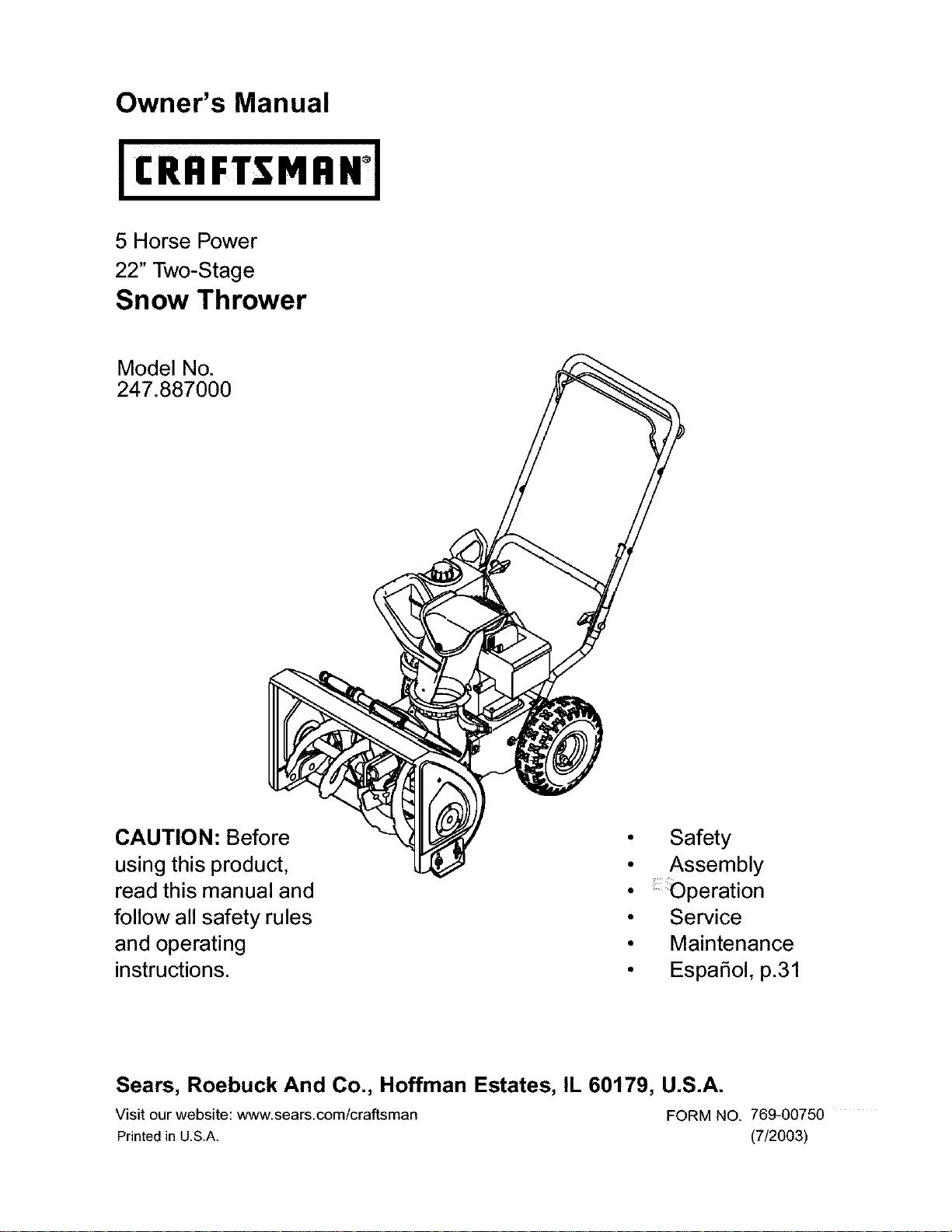
Owner's Manual
5 Horse Power
22" Two-Stage
Snow Thrower
Model No.
247.887000
CAUTION: Before
using this product,
read this manual and
follow all safety rules
and operating
instructions.
Sears, Roebuck And Co., Hoffman Estates, IL 60179, U.S.A.
Visit our website: www.sears.com/craffsman FORM NO. 769-00750
Printed in U.S.A. (7/2003)
• Safety
• Assembly
• _peration
• Service
° Maintenance
• EspaSol, p.31
Page 2
Content Page
Warranty Information .................................... 2
Safe Operation Practices .............................. 3
Assembly ...................................................... 5
Operation ...................................................... 7
Maintenance ................................................. 11
Content Page
Service & Adjustment ....................................... 13
Off-Season Storage ......................................... 15
Trouble-Shooting ............................................. 16
Parts List ......................................................... 20
Espanbl ......................................................... 30
Two -Year Warranty on Craftsman Snow Thrower
For two years from the date of purchase, when this Craftsman Snow Thrower is maintained, lubricated and tuned up according to the instruc-
tions in the owner's manual, Sears will repair, free of charge, any defect in material and workmanship.
If this Craftsman snow thrower is used for commercial or rental purposes, this warranty applies for only 30 days from the date of purchase.
This warranty does not cover:
Expendable items which become worn during normal use, such as skid shoes, shave plate and spark plugs.
Repairs necessary because of operator abuse or negligence, including bent crankshafts and the failure to maintain the equipment
according to the instructions contained in the owner's manual.
WARRANTY SERVICE iS AVAILABLE BY RETURNING THE CRAFTSMAN SNOW THROWER TO THE NEAREST SEARS PARTS & REPAIR
CENTER IN THE UNITED STATES.
This warranty applies only while this product is in use in the United States.
This warranty gives you specific legal rights and you may also have other rights which may vary from state to state.
SEARS, ROEBUCK AND CO., D/817WA, HOFFMAN ESTATES, IL 60179
Repair Protection Agreements
Congratulations on making a smart purchase.Your new Craftsman®
product is designed and manufactured for years of dependable
operation. But like all products, it may require repair from time to
time. That's when having a Repair Protection Agreement can save
you money and aggravation.
Here's what's included in the Agreement:
Expert servic e bY OUr 12,000 professional repair
specialists
Unlimited service and no charge for parts and labor on
all covered repairs
Product replacement if your covered product can't be
fixed
Discount of 10% from regular price of service and service-
related parts not covered by the agreement; also, 10% off
regular price of preventive maintenance check
Past help by phone- phone support from a Sears
technician on products requiring in-home repair, plus
convenient repair scheduling
Purchase a Repair Protection Agreement now and protect yourself
from unexpected hassle and expense.
Once you purchase the Agreement, a simple phone call is all that it
takes for you to schedule service. You can call anytime day or night,
or schedule a service appointment online. Sears has over 12,000
professional repair specialists, who have access to over 4.5 million
quality parts and accessories. That's the kind of professionalism you
can count on to help prolong the life of your new purchase for years
to come. Purchase your Repair Protection Agreement today!
Some limitations and exclusions apply. For prices and additional
information call 1-800-827-6655.
Sears Installation Service
For Sears professional installation of home appliances, garage door
openers, water heaters, and other major home items, in the U.S.A.
call 1-800-4-MY-HOME®.
Horsepower: 5
Engine Oifi SAE 5W30 Capacity: 21 oz.
Fuel: Unleaded Regular Capacity:
Spark Plug: RJ19LM
Eng he: Craftsman Eng ne Moode 143.045003
Model Number
Record both serial number and date of purchase and keep in a
safe p ace for future reference.
Page 3
_lb WARNING: This symbol points out important safety instructions which, if not followed, could endanger
the personal safety and/or property of yourself and others. Read and follow all instructions in this manual
before attempting to operate this machine. Failure to comply with these instructions may result in personal
injury. When you see this symbol--heed its warning.
,_ WARNING: Engine Exhaust, some of its constituents, and certain vehicle components contain or emit
chemicals known to State of California to cause cancer and birth defects or other reproductive harm.
DANGER: This machine was built to be operated according to the rules for safe operation in this manual. As with
any type of power equipment, carelessness or error on the part of the operator can result in serious injury. This
machine is capable of amputating hands and feet and throwing objects. Failure to observe the following safety
instructions could result in serious injury or death.
7.
Training
1. Read, understand, and follow all instructions on the
machine and in the manual(s) before attempting to
assemble and operate. Keep this manual in a safe place
for future and regular reference and for ordering
replacement parts.
2. Be familiar with all controls and their proper operation.
Know how to stop the machine and disengage these
controls quickly.
3. Never allow children under 14 years old to operate this
machine. Those 14 years old and over should read and
understand the operation instructions and safety rules in
this manual and be trained and supervised by a parent in
order to operate this equipment.
4. Never allow adults to operate this machine without proper
instruction.
5. Thrown objects can cause serious personal injury. Plan
your snow throwing pattern to avoid discharge of material
toward roads, bystanders and the like.
6. Keep bystanders, helpers, pets and children at least 75
feet from the machine while it is in operation. Stop
machine if anyone enters the area.
7. Exercise caution to avoid slipping or falling, especially
when backing up.
Preparation
1. Thoroughly inspect the area where the equipment is to be
used. Remove all door mats, newspapers, sleds, boards,
wires and other foreign objects which could be tripped
over or thrown by the auger/impeller.
2. Always wear safety glasses or eye shields during
operation and while performing an adjustment or repair to
protect your eyes. Thrown objects which ricochet can
cause serious injury to the eyes.
3. Do not operate without wearing adequate winter outer
garments. Do not wear jewelry, long scarves or other
loose clothing which could become entangled in moving
parts. Wear footwear which will improve footing on
slippery surfaces.
4. Use agrounded three wire extension cord and receptacle
for all units with electric start engines.
5. Adjust collector housing height to clear gravel or crushed
rock surfaces.
6. Disengage all bails before starting the engine.
Never attempt to make any adjustments while engine is
running, except where specifically recommended in the
operator's manual.
8.
Let engine and machine adjust to outdoor temperature
before starting to clear snow.
9.
To avoid personal injury or property damage use extreme
care in handling gasoline. Gasoline is extremely
flammable and the vapors are explosive. Serious
personal injury can occur when gasoline is spilled on
yourself or your clothes which can ignite. Wash your skin
and change clothes immediately.
a. Use only an approved gasoline container.
b. Extinguish all cigarettes, cigars, pipes and other
sources of ignition.
c. Never fuel machine indoors.
d. Never remove gas cap or add fuel while the
engine is hot or running.
e. Allow engine to cool at least two minutes before
refueling.
f. Never over-fill fuel tank. Fill tank to no more than
½ inch below bottom of filler neck to provide space
for fuel expansion.
g. Replace gasoline cap and tighten securely.
h. If gasoline is spilled, wipe it off the engine and
equipment. Move machine to another area. Wait 5
minutes before starting the engine.
i. Never store the machine or fuel container inside
where there is an open flame, spark or pilot light
(e.g. furnace, water heater, space heater, clothes
dryer etc.).
j. Allow machine to cool at least 5 minutes before
storing.
Operation
1. Do not put hands or feet near rotating parts, in the auger/
impeller housing or discharge chute. Contact with the
rotating parts can amputate hands and feet.
2. The auger/impeller bail is a safety device. Never bypass
its operation. Doing so makes the machine unsafe and
may cause personal injury.
3. The bails must operate easily in both directions and
automatically return to the disengaged position when
released.
4. Never operate with a missing or damaged discharge
chute. Keep all safety devices in place and working.
Page 4
5. Neverrunanengineindoorsorinapoorlyventilated
area.Engineexhaustcontainscarbonmonoxide,an
odorlessanddeadlygas.
6. Donotoperatemachinewhileundertheinfluenceof
alcoholordrugs.
7. Mufflerandenginebecomehotandcancauseaburn.Do
nottouch.
8. Exerciseextremecautionwhenoperatingonorcrossing
gravelsurfaces.Stayalertforhiddenhazardsortraffic.
9. Exercisecautionwhenchangingdirectionandwhile
operatingonslopes.
10.Planyoursnowthrowingpatterntoavoiddischarge
towardswindows,walls,carsetc.Toavoidproperty
damageorpersonalinjurycausedbyaricochet.
11.Neverdirectdischargeatchildren,bystandersandpets
orallowanyoneinfrontofthemachine.
12.Donotoverloadmachinecapacitybyattemptingtoclear
snowattoofastofarate.
13.Neveroperatethismachinewithoutgoodvisibilityor
light.Alwaysbesureofyourfootingandkeepafirmhold
onthehandles.Walk,neverrun.
14.Disengagepowertotheauger/impellerwhen
transportingornotinuse.
15.Neveroperatemachineathightransportspeedson
slipperysurfaces.Lookdownandbehindandusecareif
youarebackingup.
16.Ifthemachineshouldstarttovibrateabnormally,stopthe
engine,disconnectthesparkplugandgrounditagainst
theengine.Inspectthoroughlyfordamage.Repairany
damagebeforestartingandoperating.
17.Disengageallbailsandstopenginebeforeyouleavethe
operatingposition(behindthehandles).Waituntilthe
auger/impellercomestoacompletestopbefore
uncloggingthedischargechute,makingany
adjustments,orinspections.
18.Neverputyourhandinthedischargeorcollector
openings.Alwaysuseachuteclean-outtoolprovidedto
unclogthedischargeopening.Donotunclogdischarge
chutewhiletheengineisrunning.
19.Useonlyattachmentsandaccessoriesapprovedbythe
manufacturer(e.g.wheelweights,tirechains,cabsetc.).
20.Ifsituationsoccurwhicharenotcoveredinthismanual,
usecareandgoodjudgment.ContactyournearestSears
storeforassistanceorcallCustomerService.
Maintenance & Storage
1, Never tamper with safety devices. Check their proper
operation regularly.
2. Disengage all bails and stop engine. Wait until the auger/
impeller come to a complete stop. Disconnect the spark
plug wire and ground against the engine to prevent
unintended starting before cleaning, repairing, or
inspecting.
3. Check bolts, and screws for proper tightness at frequent
intervals to keep the machine in safe working condition.
Also, visually inspect machine for any damage.
4. Do not change the engine governor setting or over-speed
the engine. The governor controls the maximum safe
operating speed of the engine.
5. Snow thrower shave plates and skid shoes are subject to
wear and damage. For your safety protection, frequently
check all components and replace with original
equipment manufacturer's (O.EM.) parts only. "Use of
parts which do not meet the original equipment
specifications may lead to improper performance and
compromise safety!"
6. Check all controls periodically to verify they engage and
disengage properly and adjust, if necessary. Refer to the
adjustment section in this operator's manual for
instructions.
7. Maintain or replace safety and instruction labels, as
necessary.
8. Observe proper disposal laws and regulations for gas,
oil, etc. to protect the environment.
9. Prior to storing, run machine a few minutes to clear snow
from machine and prevent freeze up of auger/impeller.
10. Never store the machine or fuel centainer inside where
there is an open flame, spark or pilot light such as a water
heater, furnace ,clothes dryer etc.
11. Atways refer to the operator's manual for proper
instructions on off-season storage.
Your Responsibility
Restrict the use of this power equipment to persons who read,
understand and follow warnings and instructions in this
manual and on the machine.
Do not modify engine
To avoid serious injury or death, do not modify engine in any
way. Tampering with the governor setting can lead to a
runaway engine and cause it to operate at unsafe speeds.
Never tamper with factory setting of engine governor.
Notice regarding Emissions
Engines which are certified to comply with California and
federal EPA emission regulations for SORE (Small Off Road
Equipment) are certified to operate on regular unleaded
gasoline, and may include the following emission control
systems: Engine Modification (EM) and Three Way Catalyst
(TWC) if so equipped.
Engine Identification Decal
This decal indicates the engine's model number, specification
and teh date of manufacture. Please look at the decal on the
engine of your equipment and record these information for
future reference.
The engine identification decal also includeds engine life
specifications for the emissions-related useful life period of
the engine. This period relates to the emission compliance life
as certified by EPA and/or CARB. To find the life period
specification of the engine, please read the engine decal and
and locate the letter (enclosed by quotation marks) between
the words Moderate and Life Period. Match one of the
following letters with the letter printed on your decal. For
example, HMSK 80 models are designated as:
"C"-- 125 hours
"B" -- 250 hours
"A" -- 500 hours
Page 5
IMPORTANT: This unit is shipped with engine oil in the
crankcase, but no gasoline. After assembly, see page 8
for fuel and oil fill-up details.
Removing From Carton
1. Cut the comers of the carton and lay the sides flat
on the ground. Remove all packing inserts.
2. Remove (i) plastic bag containing owner's manual,
and (ii) electric extension cord.
3. Move the snow thrower out of the carton.
4. Make certain the carton has been completely
emptied before discarding it.
Before Assembly
NOTE: Reference to right, left, front or rear of the unit is
from the operating position unless otherwise stated.
Make sure the spark plug wire is disconnected
and moved away from the spark plug.
Cut and remove cable ties holding upper handle to
lower chute.
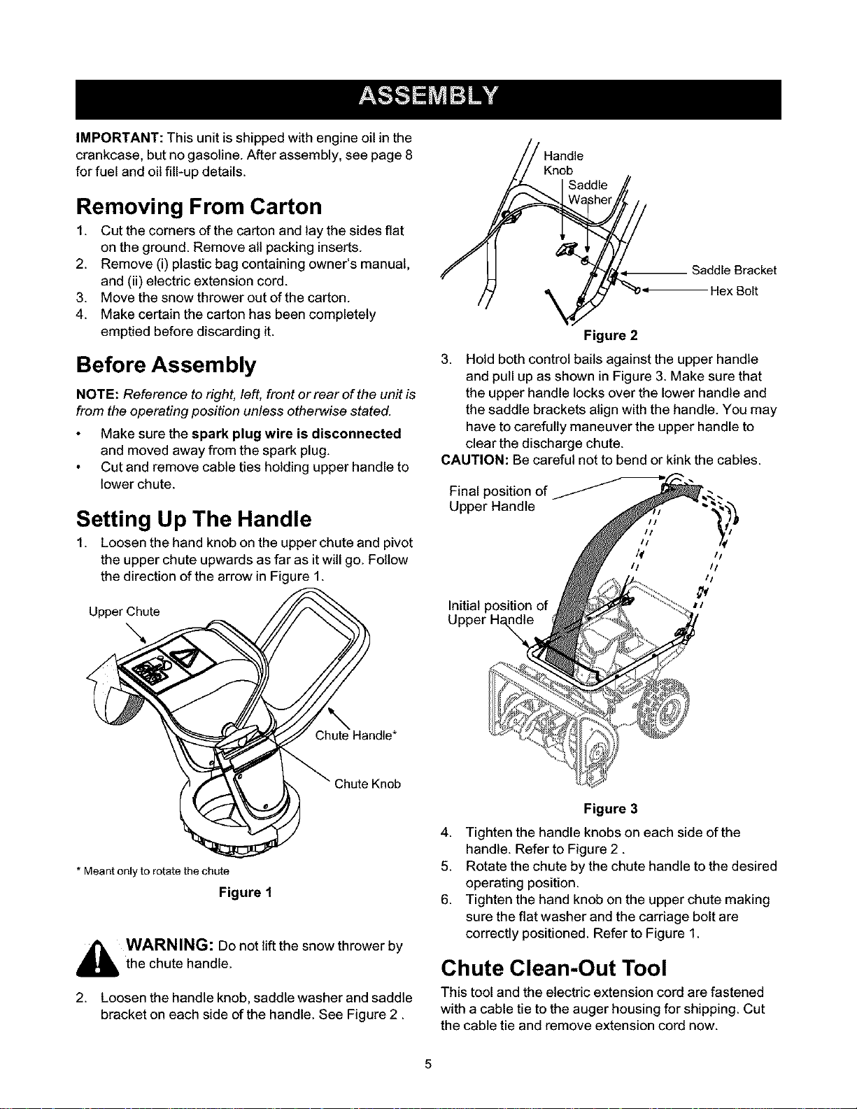
Setting Up The Handle
1. Loosen the hand knob on the upper chute and pivot
the upper chute upwards as far as itwill go. Follow
the direction of the arrow in Figure 1.
Handle
Saddle Bracket
Hex Bolt
Figure 2
3. Hold both control bails against the upper handle
and pull up as shown in Figure 3. Make sure that
the upper handle locks over the lower handle and
the saddle brackets align with the handle. You may
have to carefully maneuver the upper handle to
clear the discharge chute.
CAUTION: Be careful not to bend or kink the cables.
Final position of
Upper Handle
_f I I
II II
II
Upper Chute
Chute Handle*
Chute Knob
* Meantonly to rotate the chute
Figure 1
_hb WARNING: Do not lift the snow thrower by
the chute handle.
2. Loosen the handle knob, saddle washer and saddle
bracket on each side of the handle. See Figure 2.
Initial position of
a/
Figure 3
4. Tighten the handle knobs on each side of the
handle. Refer to Figure 2.
5. Rotate the chute by the chute handle to the desired
operating position.
6. Tighten the hand knob on the upper chute making
sure the flat washer and the carriage bolt are
correctly positioned. Refer to Figure 1.
Chute Clean-Out Tool
This tool and the electric extension cord are fastened
with a cable tie to the auger housing for shipping. Cut
the cable tie and remove extension cord now.
Page 6
Final Adjustments
IMPORTANT:Check the adjustments as instructed and
make any final adjustments necessary before operating
the unit. Check all nuts and bolts for tightness.Failure to
follow these instructions may cause damage to unit.
Tire Pressure (Pneumatic Tires)
The tires are over-inflated for shipping purposes. Check
tire pressure and reduce pressure, if needed, to 10-15
psi. Maintain equal pressure on both wheels of the
snow thrower.
pressure
,_ WARNING: Maximum tire under
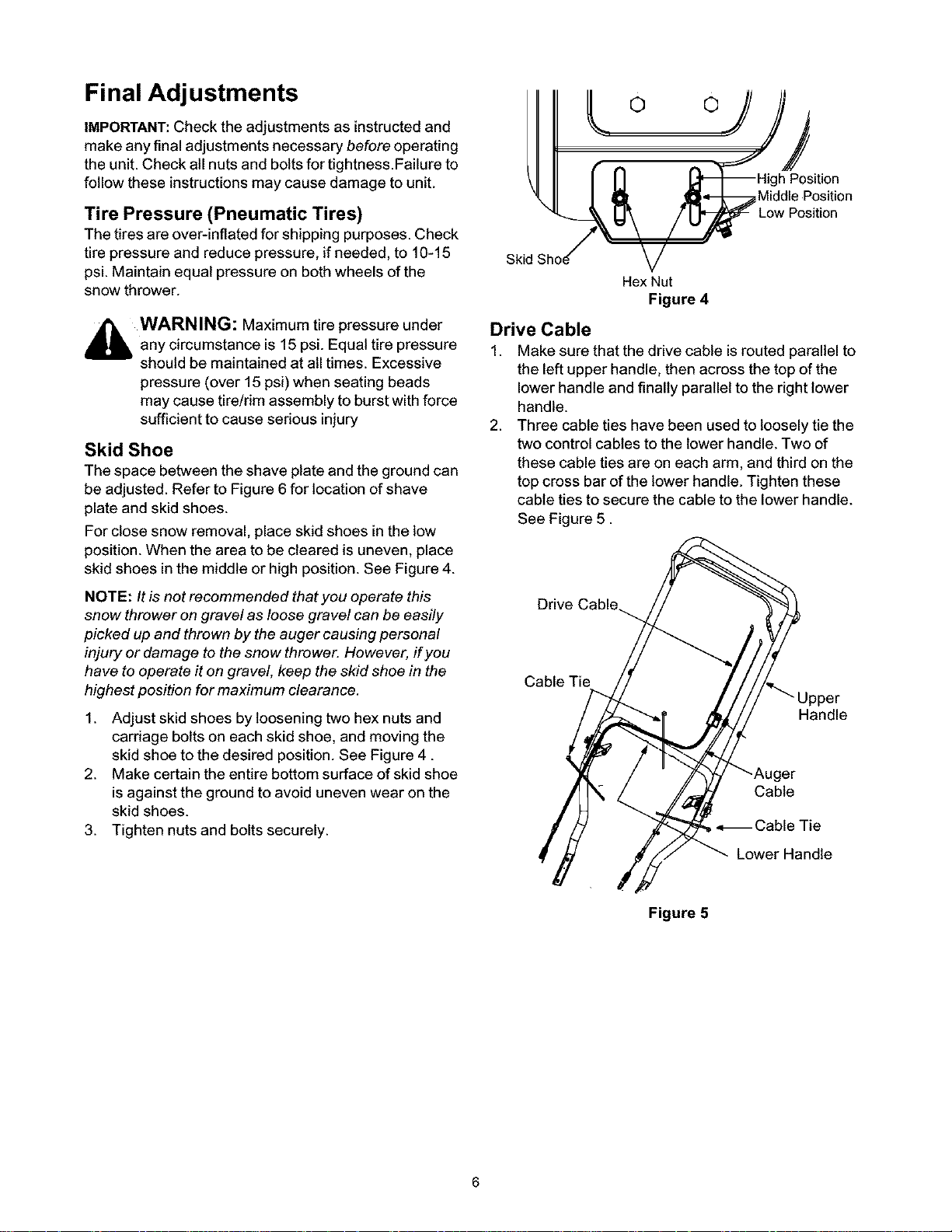
Skid Shoe
The space between the shave plate and the ground can
be adjusted. Refer to Figure 6 for location of shave
plate and skid shoes.
For close snow removal, place skid shoes in the low
position. When the area to be cleared is uneven, place
skid shoes in the middle or high position. See Figure 4.
any circumstance is 15 psi. Equal tire pressure
should be maintained at all times. Excessive
pressure (over 15 psi) when seating beads
may cause tire!rim assembly to burst with force
sufficient to cause serious injury
© ©
nPosition
Middle Position
Skid
Hex Nut
Figure 4
Drive Cable
1.
Make sure that the drive cable is routed parallel to
the left upper handle, then across the top of the
lower handle and finally parallel to the right lower
handle.
2.
Three cable ties have been used to loosely tie the
two control cables to the lower handle. Two of
these cable ties are on each arm, and third on the
top cross bar of the lower handle. Tighten these
cable ties to secure the cable to the lower handle.
See Figure 5.
Position
NOTE: Itis not recommended that you operate this
snow thrower on gravel as loose gravel can be easily
picked up and thrown by the auger causing personal
injury or damage to the snow thrower. However, if you
have to operate it on gravel, keep the skid shoe in the
highest position for maximum clearance.
1. Adjust skid shoes by loosening two hex nuts and
carriage bolts on each skid shoe, and moving the
skid shoe to the desired position. See Figure 4.
2. Make certain the entire bottom surface of skid shoe
is against the ground to avoid uneven wear on the
skid shoes.
3. Tighten nuts and bolts securely.
Drive Cable
Cable Tie
Upper
Handle
Cable
•=_ Cable Tie
Lower Handle
Figure 5
Page 7
Readthisowner'smanualandsafetyrulesbeforeoperatingyoursnowthrower.Compareillustrationbelowwith
yoursnowthrowertofamiliarizeyourselfwiththelocationofvariouscontrolsandadjustments.
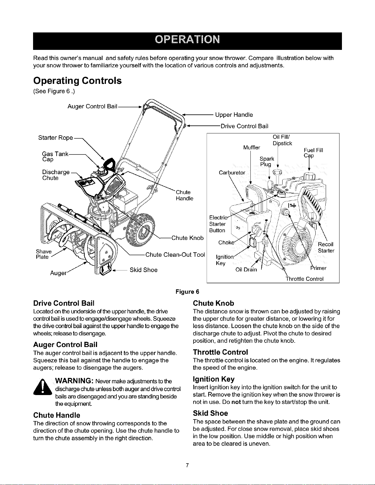
Operating Controls
(See Figure 6 .)
Auger Control Bail
Upper Handle
Drive Control Bail
Oil FiB/
Gas Tank_
Cap
Discharge
Chute
Handle
Shave
Plate Chute Clean-Out Tool lg
Skid Shoe Oil
Figure 6
Drive Control Bail
Locatedontheunderside ofthe upperhandle, thedrive
controlbail isusedtoengage/disengagewheels.Squeeze
thedrive control bail against the upper handle to engage the
wheels; releaseto disengage.
Auger Control Bail
The auger control bail is adjacent to the upper handle.
Squeeze this bail against the handle to engage the
augers; release to disengage the augers.
Chute Knob
The distance snow is thrown can be adjusted by raising
the upper chute for greater distance, or lowering itfor
less distance. Loosen the chute knob on the side of the
discharge chute to adjust. Pivot the chute to desired
position, and retighten the chute knob.
Throttle Control
The throttlecontrol islocated on the engine. Itregulates
the speed of the engine.
carpi,;
Key
Muffler Dilpstick
Spark |
I Plug
Throttle Control
Fuel Fill
CI°
Recoil
Starter
i_i WARNING: Nevermake adjustments tothe
discharge chute unless bothaugerand ddvecontrol
bailsare disengaged and you are standing beside
theequipment.
Chute Handle
The direction ofsnow throwing corresponds to the
direction of the chute opening. Use the chute handle to
turn the chute assembly in the rightdirection.
Ignition Key
Insert ignition key into the ignition switch for the unit to
start. Remove the ignition key when the snow thrower is
not in use. Do riot turn the key to start/stop the unit.
Skid Shoe
The space between the shave plate and the ground can
be adjusted. For close snow removal, place skid shoes
in the low position. Use middle or high position when
area to be cleared is uneven.
Page 8
Before Starting Engine
Engine Oil
The unit isshipped with oil inengine. For subsequent
fill-ups, refer to grade specifications on page 11. Follow
the steps below before starting engine each time.
1. Remove the dipstick from the oil fill. For location of
the oilfill, see Figure 6.
2. Check and make sure that the level of oil is up to
the FULL mark on the dipstick.
3. If the oillevel is not upto FULL, pour fresh oil slowly
through the plug. Replace dipstick and check oil
level again.
Gasoline
_b WARNING: Since gasoline is flammable,
IMPORTANT:Your snow thrower is
equipped with a plasticfuel tank insertfor
shipping purposes. Please discard it
before filling up gasoline for the first time.
CAUTION: Never use engine or carburetor cleaner
products in the fuel tank.
use caution when handling or storing it. Do not
fill fuel tank while the engine is running, when it
is hot or in an enclosed area. Keep your snow
thrower away from any open flame or an
electrical spark and do not smoke while filling
the fuel tank.
Always use clean, fresh, unleaded
grade automotive gasoline.
Avoid using alcohol blended fuels which can attract
moisture and damage fuel system if left in tank
dudng storage. See Off-Season Storage section on
page 15.
Fill the fuel tank outdoors and use a funnel or spout
to prevent spilling. The gasoline container should
be clean and free ofrust or other foreign particles.
Never fill the fuel tank completely. Fillthe tank to
within 1/4"-1/2" from the top to provide space for
expansion of fuel.
Wipe off any spilled fuel before starting the engine.
To Start Engine
plug and is designed to operate on 120 volt AC
household current.
Cold Start
1. Determine whether your house widng isa three-
wire grounded system. Ask a licensed electrician if
you are not certain.
_ WARNING: The electdc starter must be
2.
NOTE: When connecting the power cord, always
connect cord to starter on engine first, then plug the
other end into a three-hole grounded 120 Volt
receptacle. When disconnecting the power cord,
always unplug the end from the three-hole, grounded
receptacle first.
3. Attach spark plug wire to spark plug.
4. Make sure that the auger control bail and the drive
5. Remove the keys from the plastic bag. Push key
6. Move the choke knob to FULL choke position.
7. Move throttle control to the FAST position.
8. Turn fuel valve on, if so equipped.
9. Connect power cord to the switch box on engine.
10. Plug the other end of the power cord intoa three-
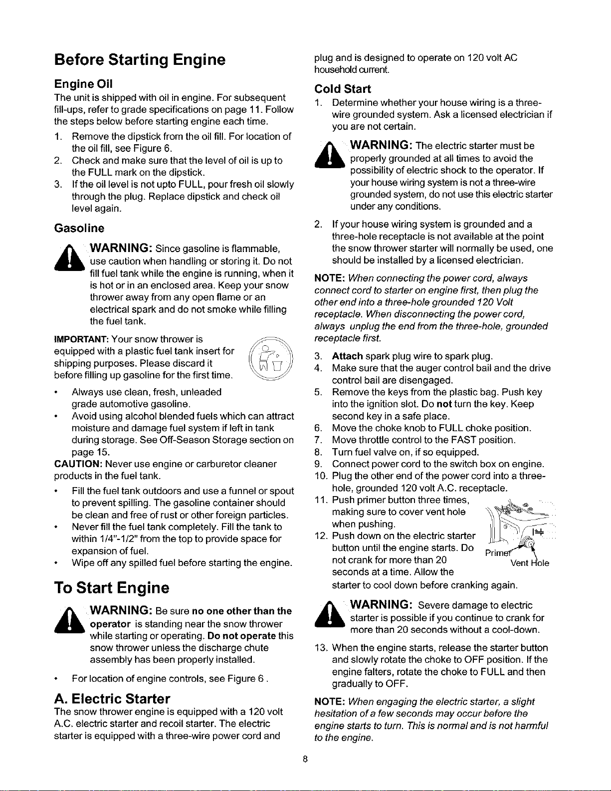
11. Push pdmer button three times,
12. Push down on the electric starter
propedy grounded at all times to avoid the
possibilityof electric shock to the operator. If
yourhouse wiring system is not a three-wire
grounded system, do notuse thiselectric starter
under any conditions.
If your house wiring system is grounded and a
three-hole receptacle is not available at the point
the snow thrower starter will normally be used, one
should be installed by a licensed electrician.
control bail are disengaged.
into the ignition slot. Do not turn the key. Keep
second key in a safe place.
hole, grounded 120 volt A.C. receptacle.
making sure to cover vent hole
when pushing.
button until the engine starts. Do
not crank for more than 20
seconds at a time. Allow the
starter to cool down before cranking again.
_ WARNING: Be sure no one other than the
operator is standing near the snow thrower
while starting or operating. Do not operate this
snow thrower unless the discharge chute
assembly has been properly installed.
For location of engine controls, see Figure 6.
A. Electric Starter
The snow thrower engine is equipped with a 120 volt
A.C. electric starter and recoil starter. The electric
starter is equipped with a three-wire power cord and
_ WARNING: Severe damage to electric
starter is possible if you continue to crank for
more than 20 seconds without a cool-down.
13. When the engine starts, release the starter button
and slowly rotate the choke to OFF position. Ifthe
engine falters, rotate the choke to FULL and then
gradually to OFF.
NOTE: When engaging the electric starter, a slight
hesitation ofa few seconds may occur before the
engine starts to turn. This is normal and is not harmful
to the engine.
Page 9
14. Disconnect the power cord from the receptacle first
and then from the switch box on the engine.
15. Allow the engine to warm up for a few minutes
because the engine will not develop full power until
it reaches operating temperature. Operate at FULL
throttle when throwing snow.
Warm Start
If restarting a warm engine, rotate choke to OFF
instead of FULL and press the starter button. Do not
push the primer button.
B. Recoil Starter
Make sure that the auger control bail and the drive
controlbail are released.
Cold Start
1. Move throttle control to FAST position.
2. Push key into the ignitionslot so that itsnaps into
place. Do not turn key. Remove plastic bag and
keep the second key in a safe place.
3. Rotate choke control to FULL choke position.
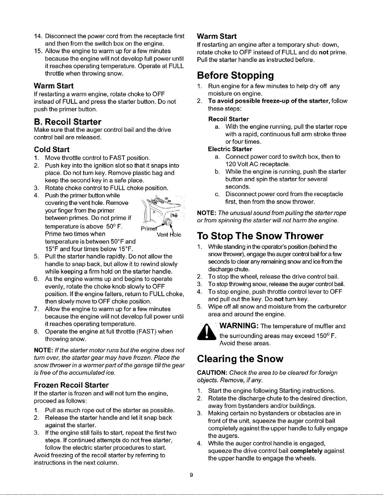
4. Push theprimer buttonwhile
covering the vent hole. Remove
your finger from the primer
between primes. Do not prime if
temperature isabove 50° F.
Prime two times when
temperature isbetween 50°F and
15°F and four times below 15°F.
5. Pull the starter handle rapidly. Do not allow the
handle to snap back, but allow itto rewind slowly
while keeping a firm hold on the starter handle.
6. As the engine warms up and begins to operate
evenly, rotate the choke knob slowly to OFF
position. If the engine falters, return to FULL choke,
then slowly move to OFF choke position.
7. Allow the engine to warm up for a few minutes
because the engine will not develop full power until
it reaches operating temperature.
8. Operate the engine at full throttle (FAST) when
throwing snow.
NOTE: If the starter motor runs but the engine does not
turn over, the starter gear may have frozen. Place the
snow thrower in a warmer part of the garage till the gear
is free of the accumulated ice.
Frozen Recoil Starter
If the starter is frozen and wilt not turn the engine,
proceed as follows:
1. Pull as much rope out of the starter as possible.
2. Release the starter handle and let it snap back
against the starter.
3. If the engine still fails to start, repeat the first two
steps. If continued attempts do not free starter,
follow the electric starter procedures to start.
Avoid freezing of the recoil starter by referring to
instructions in the next column.
Warm Start
If restarting an engine after a temporary shut- down,
rotate choke to OFF instead of FULL and do not prime.
Pull the starter handle as instructed before.
Before Stopping
1. Run engine for a few minutes to help dry off any
moisture on engine.
2. To avoid possible freeze-up of the starter, follow
these steps:
Recoil Starter
a. With the engine running, pullthe starter rope
with a rapid, continuous full arm stroke three
or four times.
Electric Starter
a. Connect power cord to switch box, then to
120 Volt AC receptacle.
b. While the engine is running, push the starter
button and spin the starter for several
seconds.
c. Disconnect power cord from the receptacle
first, then from the snow thrower.
NOTE: The unusual sound from pulling the starter rope
or from spinning the starter will not harm the engine.
To Stop The Snow Thrower
1. While standing inthe operator's position (behind the
snow thrower), engage the auger control bailfor a few
seconds to clear any remaining snow and ice from the
discharge chute.
2. To stop the wheel, release the drive control bail.
3. To stop throwing snow, release the auger control bail.
4. To stop engine, push throttle control lever to OFF
and pull out the key. Do not turn key.
5. Wipe off all snow and moisture from the carburetor
area and around the engine.
_ WARNING: The temperature of muffler and
the surrounding areas may exceed 150° F.
Avoid these areas.
Clearing the Snow
CAUTION: Check the area to be cleared for foreign
objects. Remove, if any.
1. Start the engine following Starting instructions.
2. Rotate the discharge chute to the desired direction,
away from bystanders and/or buildings.
3. Making certain no bystanders or obstacles are in
front of the unit, squeeze the auger control bail
completely against the upper handle to fully engage
the augers.
4. While the auger control handle is engaged,
squeeze the drive control bail completely against
the upper handle to engage the wheels.
Page 10
5. Asthesnowthrowerstartstomove,maintainafirm
holdonthehandle,andguidethesnowthrower
alongthepathtobecleared.
6. Releasethebailstostopthesnowthrowingaction
andforwardmotion.
NOTE:Your unit is equipped with a clutch in the
transmission. If the wheels stop turning while trying to
discharge large volumes of snow, immediately
disengage drive control bail and allow rotating augers to
discharge snow from the housing. Continue operation
on a narrower stretch with less volume of snow.
7. On each succeeding pass, readjust the chute
deflector to the desired position and slightly overlap
the previously cleared path.
Operating Tips
NOTE: Allow the engine to warm up for a few minutes
as the engine will not develop full power until # reaches
operating temperature.
Chute Clean-Out Tool
_ ARNING: Stop engine by removing
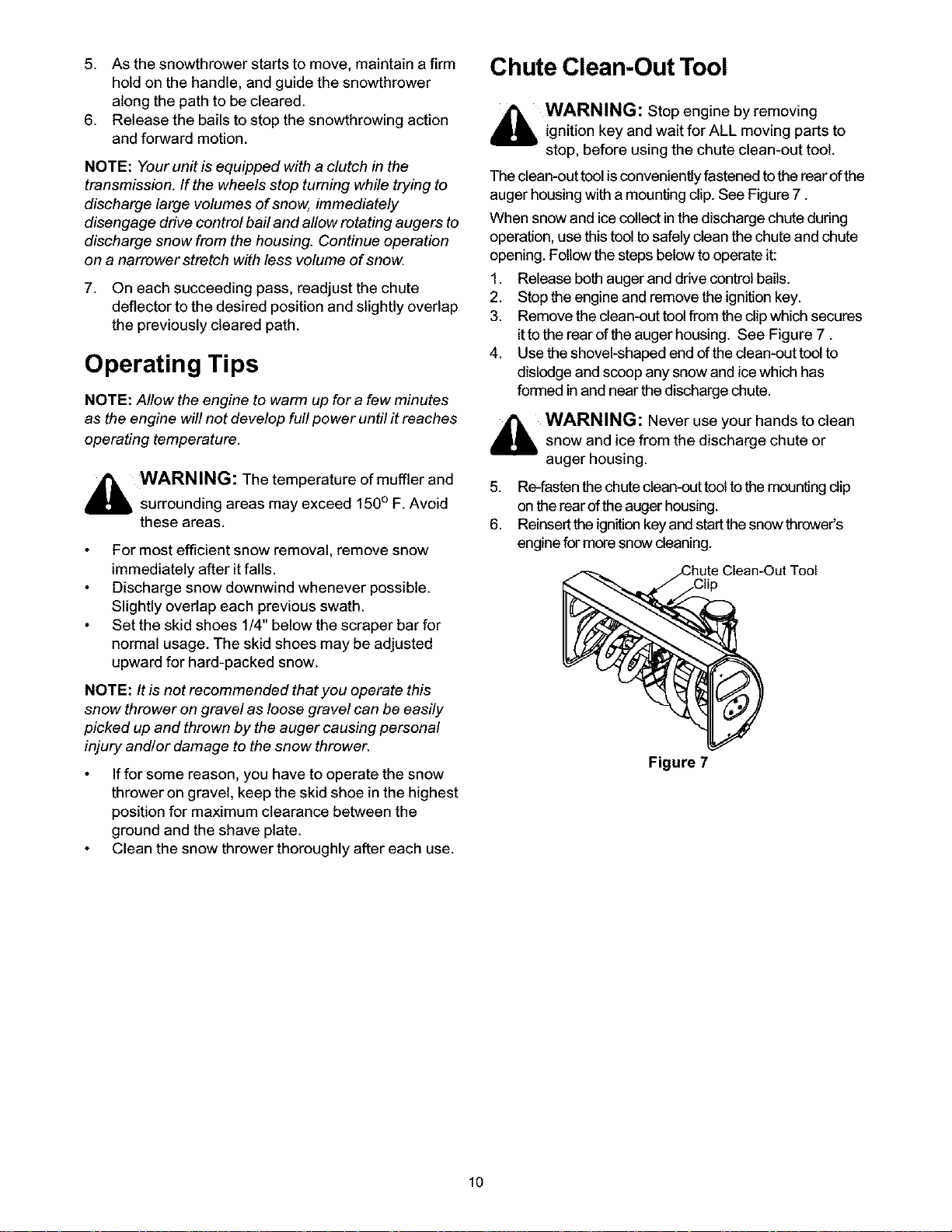
The clean-out tool isconveniently fastened to the rear ofthe
auger housing with a mounting clip. See Figure 7.
When snow and icecollect inthe discharge chute during
operation, use this tool to safely clean the chute and chute
opening. Follow the steps below to operate it:
1. Release both auger and drive control bails.
2. Stop the engine and remove the ignition key.
3. Remove the clean-out tool from the clip which secures
4. Use the shovel-shaped end ofthe clean-out tool to
_ WARNING: Never use your hands to clean
ignition key and wait for ALL moving parts to
stop, before using the chute clean-out tool.
ittothe rear ofthe auger housing. See Figure 7.
dislodge and scoop any snow and ice which has
formed in and near the discharge chute.
snow and ice from the discharge chute or
auger housing.
,_ WARNING: The temperature of muffler and
NOTE: Itis not recommended that you operate this
snow thrower on gravel as loose gravel can be easily
picked up and thrown by the auger causing personal
injury and/or damage to the snow thrower.
surrounding areas may exceed 150° F. Avoid
these areas.
For most efficient snow removal, remove snow
immediately after itfalls.
Discharge snow downwind whenever possible.
Slightly overlap each previous swath.
Set the skid shoes 1/4" below the scraper bar for
normal usage. The skid shoes may be adjusted
upward for hard-packed snow.
If for some reason, you have to operate the snow
thrower on gravel, keep the skid shoe in the highest
position for maximum clearance between the
ground and the shave plate.
Clean the snow thrower thoroughly after each use.
5. Re-fasten the chute clean-out tool to the mounting dip
on the rear of theauger housing.
6. Reinsert the ignition keyand startthe snow thrower's
engine for more snow cleaning.
Figure 7
10
Page 11
General Recommendations
Always observe safety rules when performing any
maintenance.
The warranty on this snow thrower does not cover
items that have been subjected to operator abuse
or negligence. To receive full value from the
warranty, operator must maintain the snow
thrower as instructed in this manual.
Some adjustments will have to be made
periodically to maintain your unit properly.
All adjustments in the Service and Adjustments
section of this manual should be checked at least
once each season.
Follow maintenance schedule on next page.
Periodically check all fasteners and make sure
these are tight.
_bb WARNING: Always stop the engine and
disconnect the spark plug wire before
performing any maintenance or adjustments.
Maintenance Schedule
Maint, Tasks Every25
Product:
Lubricate pivot points I I I I _, I
Check V belts
Engine:
Check engine oil _ I I I I I I I
hours
,t
Service Dates
Change engine oiI
Check spark plug
Replace spark plug
Empty fue! system
,t ,t
Maintaining The Engine
Engine Oil
Only use high quality detergent oil rated with API
service classification SF, SG or SH. Refer to the table
below to select oil:
Oil Type Temperature Recommended Oil
Straight Grade Above 32°F SAE 30W
Multi Grade 0°F to 32°F SAE 5W30 or
SAE lOW
Synthetic Below 0°F SAE 0W30
NOTE: Although multi-viscosity oils (5W30, 10W30
etc.) improve starting in cold weather, these multi-
viscosity oils will result in increased off consumption
when used above 32°F. Check your snow thrower's
engine oil level more frequently to avoid possible
engine damage from running low on oil.
Refer to the viscosity chart for proper selection of
engine oil.
4
,t
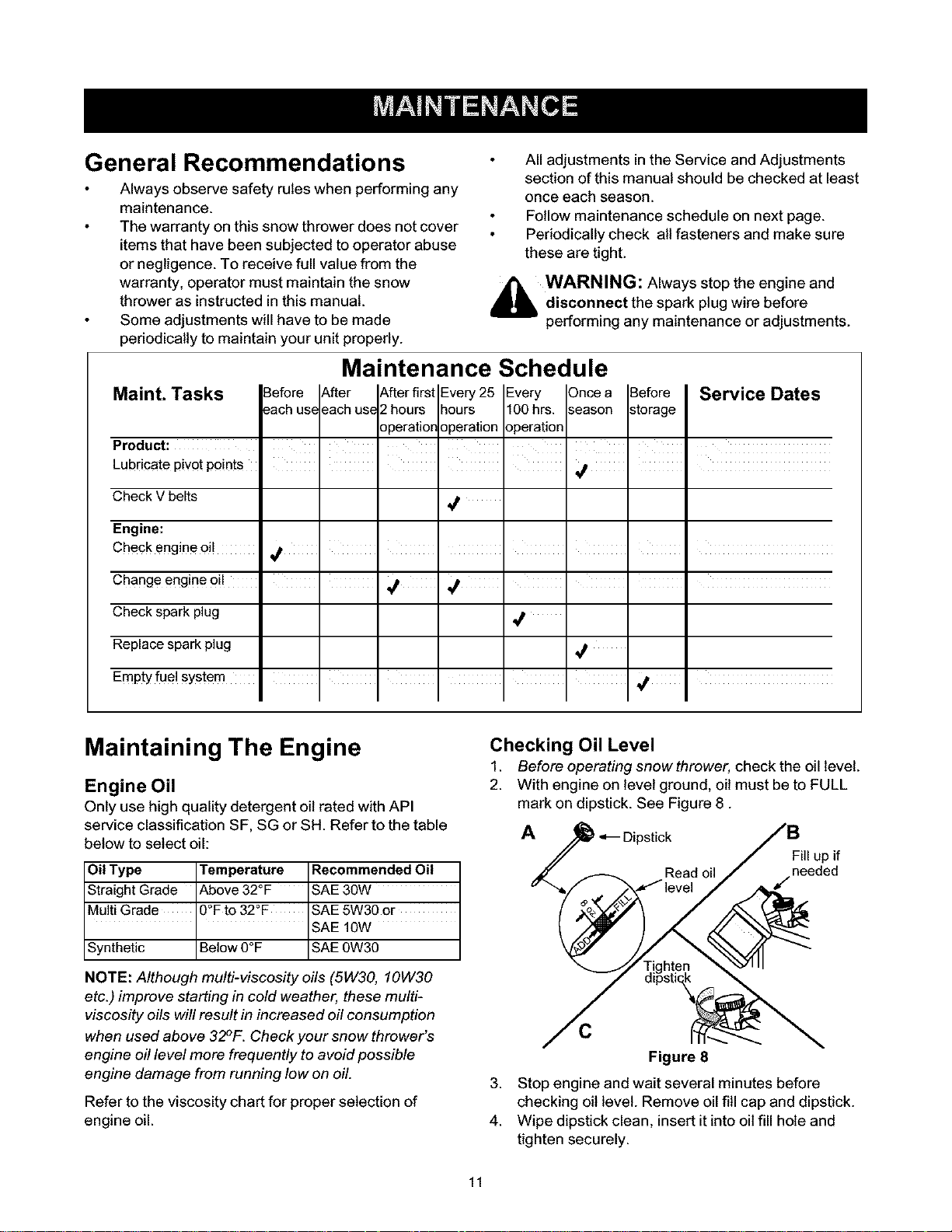
Checking Oil Level
1. Before operating snow thrower, check the oil level.
2. With engine on level ground, oil must be to FULL
mark on dipstick. See Figure 8.
A
Fill up if
J needed
C
Figure 8
3.
Stop engine and wait several minutes before
checking oil level. Remove oil fill cap and dipstick.
4.
Wipe dipstick clean, insert it into oil fill hole and
tighten securely.
11
Page 12
5. Remove dipstick and check. If oil is not up to the
FULL mark on dipstick, add oil.
Changing Oil
Change engine oil after first two hours of operation and
every 25 hours thereafter.
In order to change oil, you will have tofirst drain the
spent engine oil from the engine and then refill with
fresh oil.
1. Drain oil while engine iswarm. Remove oil drain
plug located at the bottom of the recoil starter of the
engine. Catch oil in a suitable container.
2. When engine is drained of all oit, replace drain plug
securely.
3. Remove the dipstick from the oilfill. For location of
the oilfill, see Figure 6. Pour fresh oil slowly
through the plug. Replace dipstick.
4. Check and make sure that the level of oil is up to
the FULL mark on the dipstick.
Spark Plug
Clean spark plug and reset the electrode gap to 0.030"
at least once a season or every 100 hours of operation;
replace every 200 hours of operation.
Clean area around the spark plug base.
Remove and inspect the spark plug.
Replace the spark plug if electrodes are pitted,
bumed, or the porcelain is cracked. See Figure 9.
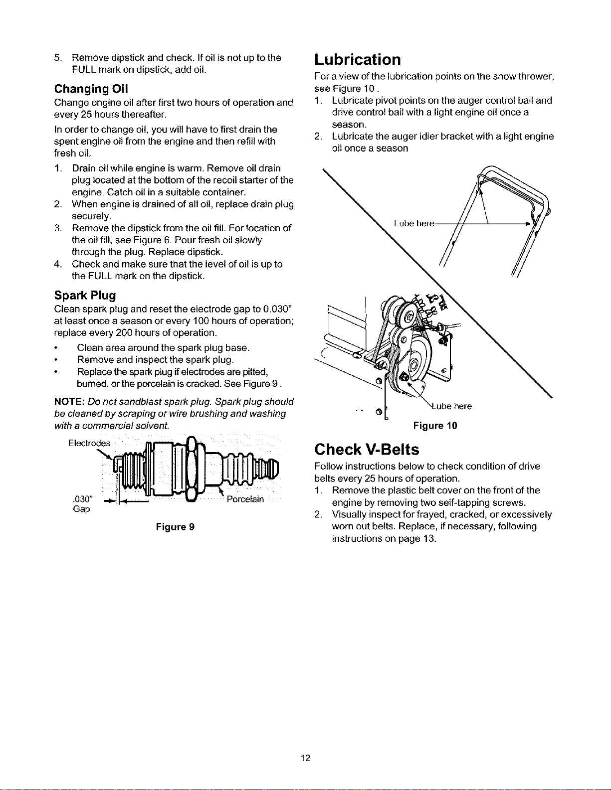
Lubrication
Fora view ofthe lubrication points on the snow thrower,
see Figure 10.
1. Lubricate pivotpoints on the auger control bail and
ddve control bail with a light engine oilonce a
season.
2. Lubdcate the auger idler bracket with a light engine
oil once a season
Lube
NOTE: Do not sandblast spark plug. Spark plug should
be cleaned by scraping or wire brushing and washing
with a commercial solvent.
Electrodes
.030"
Gap
Figure 9
Porcelain
here
Figure 10
Check V-Belts
Follow instructions below to check condition of drive
belts every 25 hours of operation.
1. Remove the plastic belt cover on the front of the
engine by removing two self-tapping screws.
2. Visually inspect for frayed, cracked, or excessively
worn out belts. Replace, if necessary, following
instructions on page 13.
12
Page 13
_bb ARNING: Always stop the engine of the
snow thrower, disconnect spark plug wire and
move it away from the spark plug before
performing any adjustments or repairs.
WARNING: Never attempt to clean the
discharge chute or make any adjustments
while the engine is running.
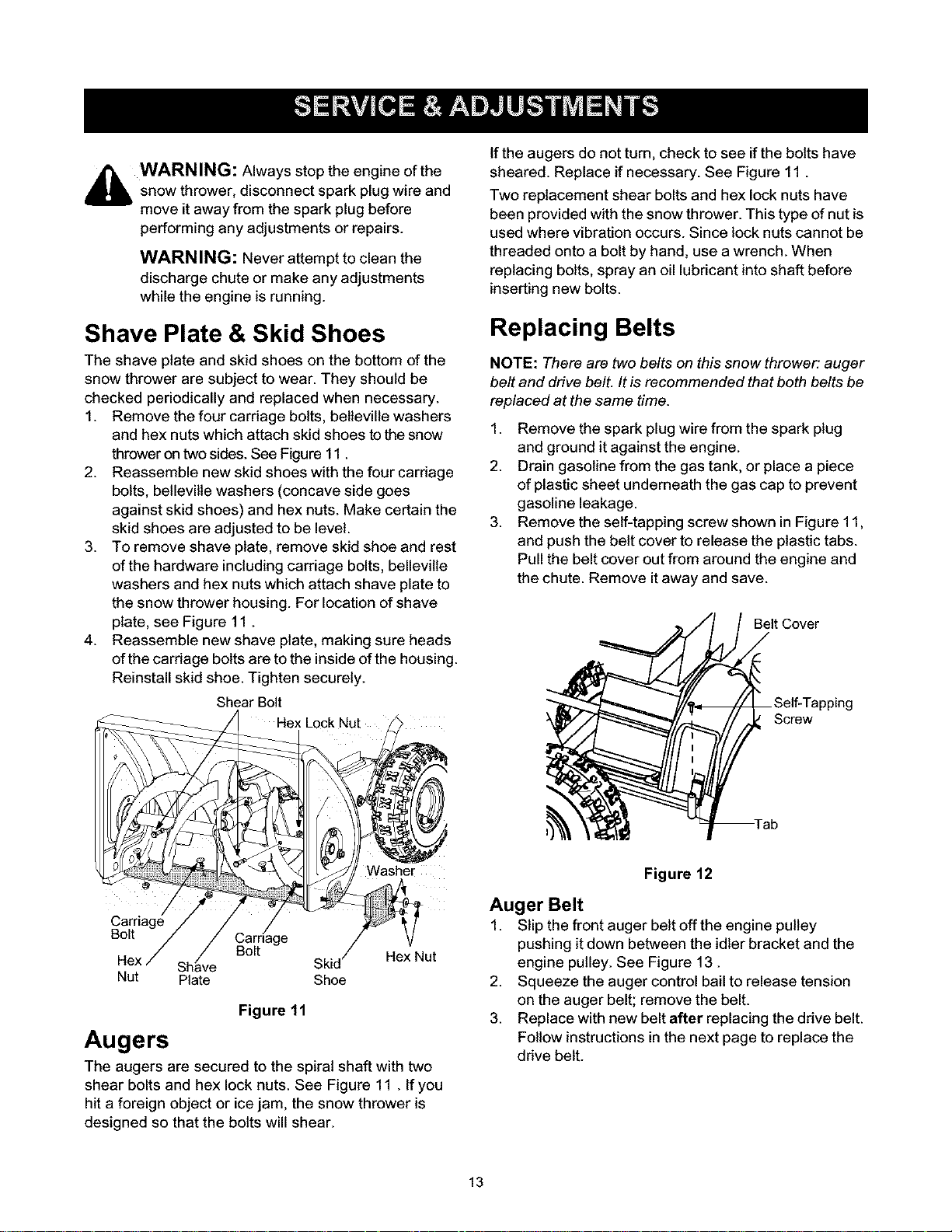
If the augers do not turn, check to see if the bolts have
sheared. Replace if necessary. See Figure 11.
Two replacement shear bolts and hex lock nuts have
been provided with the snow thrower. This type of nut is
used where vibration occurs. Since lock nuts cannot be
threaded onto a bolt by hand, use a wrench. When
replacing bolts, spray an oil lubricant into shaft before
inserting new bolts.
Shave Plate & Skid Shoes
The shave plate and skid shoes on the bottom of the
snow thrower are subject to wear. They should be
checked periodically and replaced when necessary.
1. Remove the four carriage bolts, belleville washers
and hex nuts which attach skid shoes tothe snow
thrower on two sides. See Figure 11.
2. Reassemble new skid shoes with the four carriage
bolts, bellevilte washers (concave side goes
against skid shoes) and hex nuts. Make certain the
skid shoes are adjusted to be level.
3. To remove shave plate, remove skid shoe and rest
of the hardware includingcarriage bolts, belleville
washers and hex nuts which attach shave plate to
the snow thrower housing. For location of shave
plate, see Figure 11.
4. Reassemble new shave plate, making sure heads
of the carriage bolts are to the inside of the housing.
Reinstall skid shoe. Tighten securely.
Shear Bolt
Replacing Belts
NOTE: There are two belts on this snow thrower: auger
belt and drive belt. It is recommended that both belts be
replaced at the same time.
1. Remove the spark plug wire from the spark plug
and ground it against the engine.
2. Drain gasoline from the gas tank, or place a piece
of plastic sheet underneath the gas cap to prevent
gasoline leakage.
3. Remove the self-tapping screw shown in Figure 11,
and push the belt cover to release the plastic tabs.
Pull the belt cover out from around the engine and
the chute. Remove it away and save.
Belt Cover
Screw
Carriage
Bolt
Nut Plate Shoe
a[riage / V
Bolt Skid/ Hex Nut
Figure 11
Augers
The augers are secured to the spiral shaft with two
shear bolts and hex lock nuts. See Figure 11 . If you
hit a foreign object or ice jam, the snow thrower is
designed so that the bolts will shear.
Figure 12
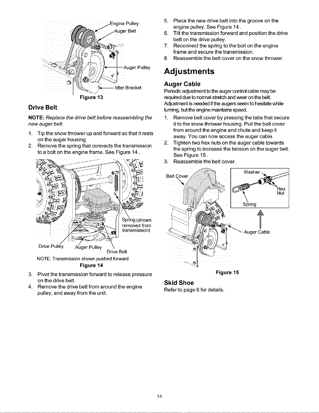
Auger Belt
1. Slip the front auger belt off the engine pulley
pushing it down between the idler bracket and the
engine pulley. See Figure 13.
2. Squeeze the auger control bail to release tension
on the auger belt; remove the belt.
3. Replace with new belt after replacing the drive belt.
Follow instructions inthe next page to replace the
drive belt.
13
Page 14
A _ Engine Pulley
uoerBe,,
5. Place the new drive belt into the groove on the
engine pulley. See Figure 14.
6. Tilt the transmission forward and position the drive
belt on the drive pulley.
7. Reconnect the spring to the bolt on the engine
frame and secure the transmission.
8. Reassemble the belt cover on the snow thrower.
Adj ustments
iiiii iiiiiiii_
Figure 13
Drive Belt
NOTE: Replace the drive belt before reassembling the
new auger belt.
1. Tip the snow thrower up and forward so that it rests
on the auger housing.
2. Remove the spring that connects the transmission
to a bolt on the engine frame. See Figure 14.
removed from
transmission)
Auger Cable
Pedodicadjustment to the auger control cablemay be
required due to normal stretch and wear on the belt.
Adjustment is needed iftheaugers seem to hesitatewhile
taming, but the engine maintains speed.
1. Remove belt cover by pressing the tabs that secure
itto the snow thrower housing. Pull the belt cover
from around the engine and chute and keep it
away. You can now access the auger cable.
2. Tighten two hex nuts on the auger cable towards
the spring to increase the tension on the auger belt.
See Figure 15.
3. Reassemble the belt cover.
Belt
Nut
Drive
Drive Belt
NOTE:Transmission shown pushedforward
Figure 14
3.
Pivot the transmission forward to release pressure
on the drive belt.
4.
Remove the drive belt from around the engine
pulley, and away from the unit.
Figure 15
Skid Shoe
Refer to page 6 for details.
14
Page 15
If the snow thrower wilt not be used for 30 days or
longer, or if it is the end of the snow season when the
last possibility of snow is gone, the equipment needs to
be stored properly. Follow storage instructions below to
ensure top performance from the snow thrower for
many more years.
Preparing Engine
_ WARNING: Do not drain carburetor if using
fuel stabilizer. Never use engine or carburetor
cleaning products in the fuel tank or permanent
damage may occur.
,_ WARNING: Never store snow thrower with
NOTE: Itis important to prevent gum deposits from
forming in essential fuel system parts ofthe engine
such as the carburetor, fuel Filter,fuel hose or tank
during storage.
CAUTION: Alcohol blended fuels (called gasohot or
using ethanol or methanol) can attract moisture which
leads to separation and formation of acids dudng
storage. Acidic gas can damage the fuel system of an
engine while in storage.
To avoid engine problems, the fuel system should be
emptied before storage for 30 days or longer. Follow
these instructions to prepare your snow thrower for
storage:
_ WARNING: Drain fuel into an approved
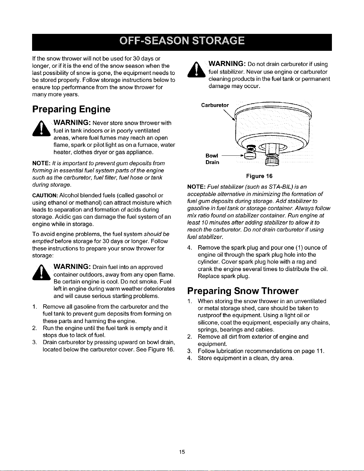
1. Remove all gasoline from the carburetor and the
2. Run the engine until the fuel tank is empty and it
3. Drain carburetor by pressing upward on bowl drain,
fuel in tank indoors or in poorly ventilated
areas, where fuel fumes may reach an open
flame, spark or pilot light as on a furnace, water
heater, clothes dryer or gas appliance.
container outdoors, away from any open flame.
Be certain engine is coot. Do not smoke. Fuel
left in engine during warm weather deteriorates
and will cause sedous starting problems.
fuel tank to prevent gum deposits from forming on
these parts and harming the engine.
stops due to lack of fuel.
located below the carburetor cover. See Figure 16.
Drain
Figure 16
NOTE: Fuel stabilizer (such as STA-BIL) is an
acceptable alternative in minimizing the formation of
fuel gum deposits during storage. Add stabilizer to
gasoline in fuel tank or storage container. Always follow
mix ratio found on stabilizer container. Run engine at
least 10 minutes after adding stabilizer to allow it to
reach the carburetor. Do not drain carburetor if using
fuel stabilizer.
4.
Remove the spark plug and pour one (1) ounce of
engine oil through the spark plug hole into the
cylinder. Cover spark plug hole with a rag and
crank the engine several times to distdbute the oil.
Replace spark plug.
Preparing Snow Thrower
1. When storing the snow thrower in an unventilated
or metal storage shed, care should be taken to
rustproof the equipment. Using a light oil or
silicone, coat the equipment, especially any chains,
springs, bearings and cables.
2. Remove all dirt from exterior of engine and
equipment.
3. Follow lubrication recommendations on page 11.
4. Store equipment in a clean, dry area.
15
Page 16

Problem Possible Cause
Engine fails to start
Engine runs erratic 1.
Engine loses power 1.
Excessive vibration 1.
Unit fails to propel 1.
itself
Unit fails to 1.
discharge snow
NOTE: This section addresses minor service issues. For further information contact Seats service by calling 1-800-
4-MY-HOME®.
1. Fuel tank empty, or stale fuel
2. Blocked fuel line
3. Choke not ON
4. Faulty spark plug
5. Key not in ignition switch
6. Spark plug wire disconnected
7. Primer not used properly
Unit running at FULL choke 1.
2.
Stale gasoline 2.
3.
Water or dirt in fuel system 3.
Spark plug wire loose 1.
2.
Gas cap vent hole plugged 2.
Loose parts or damaged auger 1.
Drive control cable not adjusted 1.
2.
Drive belt loose or damaged 2.
Discharge chute clogged 1.
2.
Shear bolt sheared.
3.
Foreign object lodged in auger
4. Auger control cable out of adjustment 4. Adjust auger control cable.
5. Auger belt loose or damaged 5. Replace auger belt.
1. Fill tank with fresh gasoline.
2. Clean the fuel line.
3. Turn Choke knob to ON position.
4. Clean, adjust or replace spark plug.
5. Insert the key fully; do not turn.
6. Attach spark plug wire to the spark
plug on the engine.
7. Prime the engine as instructed earlier.
If the carburetor is flooded due to
over-priming, wait till it dries out.
Turn choke knob to OFF position.
Siphon off existing fuel and fill tank
with fresh gasoline.
Drain fuel tank and carburetor. Fill up
with fresh gasoline.
Connect spark plug wire.
Remove ice and snow from gas cap.
Be certain that vent hole is clear.
Stop the engine immediately and
disconnect spark plug wire. Tighten all
bolts and nuts. Ifvibration continues,
contact Sears service center.
Adjust drive control cable following
earlier instructions.
Replace drive belt.
Stop engine and disconnect spark
plug wire. Clean discharge chute and
inside of auger housing.
2. Replace shear bolt.
3. Stop engine immediately and
disconnect the spark plug wire.
Remove object from auger.
Remedy
16
Page 17

California & US EPA Emission Control Warranty Statement
The U. S. Environmental Protection Agency ("EPA"), the
California Air Resources Board ("CARB") and Tecumseh
Products Co. are pleased to explain the Federal and
California Emission Control Systems Warranty on your new
small off-road engine.
tn California, new 1995 and later small off-road engines must
be designed, built and equipped to meet the State's stringent
anti-smog standards, tn other states, new 1997 and later
model year engines must be designed, built and equipped, at
the time of sale, to meet the U.S. EPA regulations for small
non-road engines.
Tecumseh Products Co. wilt warrant the emission control
system on your small off-road engine for the periods of time
listed below, provided there has been no abuse, neglect,
unapproved modification, or improper maintenance of your
small off-road engine. Your emission control system may
include parts such as the carburetor, ignition system and
exhaust system. Also included may be the compression
release system and other emission-related assemblies.
Where a warrantable condition exists, Tecumseh Products
Co. wilt repair your small off-road engine at no cost to you for
diagnosis, parts and labor.
Manufacturer's Emission Control System
Warranty Coverage
Emission control systems on 1995 and later model year
California small off-road engines are warranted for two years
as hereinafter noted. In other states, 1997 and later model
year engines are also warranted for two years, if, during such
warranty period, any emission-related part on your engine is
defective in materials or workmanship, the part wilt be
repaired or replaced by Tecumseh Products Co.
Owner's Warranty Responsibilities
As the small off-road engine owner, you are responsible for
the performance of the required maintenance listed in your
Owner's Manual, but Tecumseh Products Co. wilt not deny
warranty solely due to the tack of receipts or for your failure to
provide written evidence of the performance of all scheduled
maintenance.
As the small off-road engine owner, you should, however, be
aware that Tecumseh Products Co. may deny you warranty
coverage if your small off-road engine or a part thereof has
failed due to abuse, neglect, improper maintenance or
unapproved modifications. You are responsible for presenting
your small off-road engine to a Tecumseh Authorized Service
Outlet (any Tecumseh Registered Service Dealer. Tecumseh
Authorized Service Distributor or Tecumseh Central
Warehouse Distributor) as soon as a problem exists. The
warranty repairs should be completed ina reasonable amount
of time, not to exceed 30 days.
Warranty service can be arranged by contacting either
Authorized Tecumseh Servicing Dealer or bycontacting
Tecumseh Products Co., c/o Service Manager, Engine and
Transmission Group Service Division, 900 North Street,
Grafton, WI 53024-1499. Telephone 1-262-377-2700 [or in
USA/Canada call 1-800-558-5402] or see your local
telephone yellow pages under "Engines, Gasoline" for the
name, address and telephone number of aAuthorized
Tecumseh Servicing Dealer near you.
Important Note
This warranty statement explains your rights and obligations
under the Emission Control System Warranty ("ECS
Warranty") which is provided to you by Tecumseh Products
Co. pursuant to California law. Tecumseh Products Co. also
provides to original purchasers of new Tecumseh Products
Co. engines. The Tecumseh Products Co. Limited Warranties
for New Tecumseh Engine and Electronic ignition Modules
("Tecumseh Products Co. Warranty") which is enclosed with
all new Tecumseh Products Co. engines on a separate sheet.
The ECS Warranty applies only to the emission control
system of your new engine.To the extent that there is any
conflict in terms between the ECS Warranty and the
Tecumseh Products Co. Warranty, the ECS Warranty shall
apply except in any circumstances in which the Tecumseh
Products Co. Warranty may provide a longer warranty period.
Both the ECS Warranty and the Tecumseh Products Co.
Warranty describe important rights and obligations with
respect to your new engine.
Warranty service can only be performed by a Tecumseh
Products Co. Authorized Servicing Dealer. At the time of
requesting warranty service, evidence must be presented of
the date of sale to the original purchaser. The purchaser shall
pay any charges for making service calls and/or for
transporting the products to and from the place where the
inspection and/or warranty work is performed. The purchaser
shall be responsible for any damage or loss incurred in
connection with the transportation of any engine or any part(s)
thereof submitted for inspection and/or warranty work.
tfyou have any questions regarding your warranty rights and
responsibilities, you should contact Tecumseh Products Co.
at 1-262-377-2700 or in USA/Canada call 1-800-558-5402.
17
Page 18

Emission Control System Warranty
Emission Control System Warranty ("ECS Warranty") for warranted for the remainder of the ECS Warranty Period prior
1995 and later model year California small off-road engines to the first scheduled replacement point for such emissions-
(for other states, 1997 and later model year engines): related part.
A. APPLICABILITY: This warranty shall apply to 1995 and
later model year California small off-road engines (for other
states, 1997 and later model year engines). The ECS
Warranty Period shall begin on the date the new engine or
equipment is delivered to its original, end-use purchaser, and
shall continue for 24 consecutive months thereafter.
B. GENERAL EMISSIONS WARRANTY COVERAGE:
Tecumseh Products Co. warrants to the original, end-use
purchaser of the new engine or equipment and to each
subsequent purchaser that each of its small off-road engines
is:
1. Designed, built and equipped so as to conform with all
applicable regulations adopted by the Air Resources
Board pursuant to its authority in Chapters 1 and 2, Part 5,
Division 26 of the Health and Safety Code, and
2. Free from defects in materials and workmanship which,at
any time during the ECS Warranty Period, will cause a
warranted emissions-related part to fail to be identical in all
material respects to the part as described in the engine
manufacturer's application for certification.
C. The ECS Warranty only pertains to emissions-related parts
on your engine, as follows:
1.Any warranted, emissions-related parts which are not
scheduled for replacement as required maintenance in
the Owner's Manual shall be warranted for the ECS Warranty
Period. If any such part fails during the ECS Warranty Period,
it shall be repaired or replaced by Tecumseh Products Co.
according to Subsection 4 below. Any such part repaired or
replaced under the ECS Warranty shall be warranted for any
remainder of the ECS Warranty Period.
2. Any warranted, emissions-related part which is scheduled
only for regular inspection as specified in the Owner's Manual
shall be warranted for the ECS Warranty Period. A statement
in such written instructions to the effect of "repair or replace as
necessary", shall not reduce the ECS Warranty Period. Any
such part repaired or replaced under the ECS
Warranty shall be warranted for the remainder of the ECS
Warranty Period.
3. Any warranted, emissions-related part which is scheduled
for replacement as required maintenance in the Owner's
Manual, shall be warranted for the period of time prior to the
first scheduled replacement point for that part. If the part fails
prior to the first scheduled replacement, the part shall be
repaired or replaced by Tecumseh Products Co. according to
Subsection 4 below. Any such emissions-related part
repaired or replaced under the ECS Warranty, shall be
4. Repair or replacement of any warranted, emissionsrelated
part under this ECS Warranty shall be performed at no charge
to the owner at a Tecumseh Authorized Service Outlet.
5. The owner shall not be charged for diagnostic labor which
leads to the determination that a part covered by the ECS
Warranty is in fact defective, provided that such diagnostic
work is performed at a Tecumseh Authorized Service Outlet.
6. Tecumseh Products Co. shall be liable for damages to
other original engine components or approved modifications
proximately caused by a failure under warranty of an
emission-related part covered by the ECS Warranty.
7. Throughout the ECS Warranty Period, Tecumseh Products
Co. shall maintain a supply of warranted emission-related
parts sufficient to meet the expected demand for such
emission-related parts.
8. Any Tecumseh Products Co. authorized and approved
emission-related replacement part may be used in the
performance of any ECS Warranty maintenance or repair and
will be provided without charge to the owner. Such use shall
not reduce Tecumseh Products Co. ECS Warranty
obligations.
9. Unapproved add-on or modified parts may not be used to
modify or repair a Tecumseh Products Co. engine. Such use
voids this ECS Warranty and shall be sufficient grounds for
disallowing an ECS Warranty claim. Tecumseh Products Co.
shall not be liable hereunder for failures of any warranted
parts of a Tecumseh Products Co. engine caused by the use
of such an unapproved add-on or modified part.
Emission-Related Parts include the
following:
1. Carburetor Assembly and its Internal Components
a. Fuel filter
b. Carburetor gaskets
c. Intake pipe
2. Air Cleaner Assembly
a. Air filter element
3. Ignition System, including:
a. Spark plug
b. Ignition module
c. Flywheel assembly
4. Catalytic Muffler (if so equipped)
a. Muffler gasket (if so equipped)
b. Exhaust manifold (if so equipped)
5. Crankcase Breather Assembly and its Components
a. Breather connection tube
18
Page 19

Safety & Decorative Labels: Location and Part Number
777122141
777122138
777S32236
¢
777S32066
777D07445
19
Page 20

\
38
17
16
\
\ '27
25
29
17
2O
3O
37
Page 21

Craftsman Snow Thrower Model 247.887000
731-04216A CABLE FITTING
Key ,N°"
2.
3.
4.
5.
6.
7.
8.
10
9
11.
12.
13,
14,
15,
16.
17.
18,
19.
20.
part No.
710-0449
710-0605
710-0643
712-0324
720-0284
726-0157 Cable Tie
736-0119 LockWasher
736-0451 Saddle Washer
746-04007 Auger Cable
746-04008 Drive Cable
747-1161A OperatorBail
747-1214 DriveBail
749-1092A Upper Hanlde
749-1532 LowerHandle
790-00053 Handle Tab
616-04008
710-0643
710-0809
710-1652
711-1364
Carriage Screw 5/16-18 x 2.25"
Mach. Screw 1/4-20 x 1.825"
Hex Bolt5/16-18 x 1.0"
Hex Lock Nut 1/4-20
Handle KnobAssembly
TransmissionAssembly
Hex Bolt5116-18 x 1.0"
TT Screw 1/4-20 x 1.25"
TI- Screw 1/4-20 x .625"
ClevisPin
Description
Key No. Part No.
21. 712-0324
22. 712-0703A
23. 714-0474
24. 714-0507
25. 715-0249
26. 717-04066
27. 717-04073
28. 732-0429A
29, 736-0119
30. 736-0192
31. 741-0245
32. 741-0324
33, 784-0419
34, 790-00015
35. 634-0232
36, 710-0627
37. 736-0242
38. 738-1231
39. 731-04162
40, 710-1003
Description
Hex LockNut 1/4-20
NutInsert
C.otterPin
Cotter Pin
RollPin
_inion14T
Gear 70T
ExtensionSpring
LockWasher
FlatWasher
Hex Flange Bearing
Hex Flange Bearing
Drive HousingFrame
Bracket:Auger Cable
Wheel Assembly:SnowHog Gray
LockBolt 5/16-24 x 0.75"
BollWasher
Axle
BeltCover
Self-TappingScrew
21
Page 22

Craftsman Snow Thrower Model 247.887000
16
3
/
/
/
/
Shown for reference only-_._
/
/
21\
> \
2_
\
/ \
/ \
1
28
\
26
29
Shown for reference only
22
Page 23

Craftsman Snow Thrower Model 247.887000
Key No Pad No.
1. 710-0654A
2. 710-0696
3. 710-1245B
4. 143,045003
5. 736-0242
6. 736-0247
7. 736-0331
8. 736-0505
9. 736-0507
10. 748-0360
11. 750-1355
12. 750-1356
13. 754-04013
14. 754-04014
15. 756-04024
16. 756-0569
17. 712-3000
18. 756-04035
19. 738-0281
20. 736-0174
21. 784-0434
22. 710-0520
23. 736-0119
24. 712-3010
25. 05931A
26. 732-0611
27. 712-3068
28. 741-0309
29. 712-0431
30. 787-01165
Description
TT Sems Scr, 3/8-16 x 1.0"
Hex Bolt 3/8-24 x 0.875"
Lock Bolt 5/16-24 x 0.875"
Engine
Bell Washer
Flat Washer
Bell Washer
Flat Washer
Special Washer
Pulley: Adapter
Spacer
Spacer
V-Belt
V-Belt
Auger Pulley
Pulley Half
Hex Lock Nut 3/8-16
Flat Idler
Shoulder Screw 3/8-16
Wave Washer
Auger Idler Bracket
Hex Bolt 3/8-16 x 1.50"
Lock Washer 5/16
Hex Nut 5/16-18
Bearing Housing
Extension Spring
Patch Nut
Ball Bearing
Flange Lock Nut
Heat Shield: Muffler Guard
23
Page 24

Craftsman Snow Thrower Model 247.887000
@
12
1
11
22
35
48
52
2,$
Page 25

Craftsman Snow Thrower Model 247.887000
Key No. Part No.
1, 684-04037
2, 710-04071
3, 710-0451
4, 712-3068
5, 720-0284
6, 731-04388
7, 731-04426
8, 736-0159
9, 712-3027
10. 731-2636
11. 710-0134
12. 731-2643
13. 725-0157
14. 731-2635
15. 831-060000
16. 710-0451
17. 712-3010
18. 736-0242
19. 784-5580
20. 712-3004A
21. 710-0726
22. 736-0242
23. 784-5576
24. 750-04191
25. 731-04218
26. 717-1772
27. 715-0114
Description Key No. Part No.
Chute Assembly 28, 721-0327
Carriage Bolt 5/16-18 x 1.0" 29, 741-0662
Carriage Bolt 5/16-18 x0.750" 30, 736-0445
Patch Nut 31, 715-0143
Chute Knob Assembly 32, 721-0325
Chute Handle 33, 718-0186
Upper Chute 34, 736-0369
Washer 35, 741-0663
Lock Nut 1/4-20 36, 714-0161
Lower Chute 37, 717-0528A
Carriage Screw 1/4-20 x 0,62" 38, 736-0351
Chute Clean-out Tool 40, 618-0124
Cable Tie 618-0123
Mounting Bracket: Chute Tool 41, 710-0642
Chute Clean-Out Tool Assy. Comp, 42, 618-04055
Carriage Bolt 5/16-18 x0.75"
Hex Nut 5/16-18 43, 684-04021
Beleville Washer 684-04020
Skid Shoe 44, 721-0179
Flange Lock Nut 45, 741-0493A
AB Screw 5/16-12 46, 711-1020A
Bell Washer 47, 741-0493A
Shave Plate: 21,66" 48, 736-0188
Spacer 49, 741-0245
Impeller 50, 784-5618
Worm Shaft 51, 712-0429
Spiral Pin 52, 710-0890A
Description
Oil Seal
Flange Bearing
Fiat Washer
Spiral Pin
Plug
Thrust Collar
Fiat Washer
Flange Bearing
Key
Worm Gear 20T
Fiat Washer
Reducer Housing Assembly LH
Reducer Housing Assembly RH
TT Screw 1/4-20 x 0.75"
Gearbox Assembly: Auger
includes # 28 throlugh 41)
Spiral Assembly LH
Spiral Assembly RH
Oil Seal
Flange Bushing
Axle: Auger 22"
Flange Bushing
Flat Washer
Hex Flange Bearing
Hex Bearing: Housing
Hex Lock Nut 5/16-18
Shear Bolt 5/16-18 x 1,5"
25
Page 26

Craftsman 5 hp. Engine 143.045003 for Snow Thrower Model 247.887000
./340
310 _>290
307"/'O _"292
_135
342
.342A
303100
26
Page 27

Craftsman 5 hp. Engine 143.045003 for Snow Thrower Model 247.887000
Key No. Part No.
1 36469A
2 26727
4
5 30969
14 28277
15 31334
16 37729
17 31335
18 651018
19 30342
20 32600
25 36552
26 650802
30 37842
40 36073
40 36074
40 36075
41 36070
41 36071
41 36072
42 36076
42 36077
42 36078
43 20381
45 32875A
46 32610A
48 27241
49 32654
50 33158
60 29745
64 30063
64A 8345
65 650128
69 27677A
70 34674C
72 27642
72A 28582
75 27897
80 30574A
81 30590A
82 30591
83 30588A
86 650488
89 610961
90 611199
92 650815
93 650816
Description Key No. Part No.
Cylinder (Incl. 2.20.72,72A & 125) 100 34443C
Dowel Pin 101 610118
Oil Drain Extension (purchase locally) 102 651024
Extension Cap 103 651007
Washer 110 35182
Governor Rod 110A 36874
Governor Lever 119 36443
Governor Lever Clamp 120 37675
Screw, T-15, 8-32 x 19/64" 125 36471
Extension Spring 125 36472
Oil Seal 126 32644A
Blower Housing Baffle (Incl. 262) 127 650691
Screw, 1/4-20 x 5/8" 130 6021A
Crankshaft 130A 650694A
Piston, Pin & Ring Set (Std.) 130B 650818
Piston, Pin & Ring Set (.010" OS) 135 35395
Piston, Pin & Ring Set (.020" OS) 150 31672
Piston & Pin Ass'y. (Std.) (Incl. 43) 151 31673
Piston & Pin Ass'y. (.010" OS) (Incl. 43' 169 27234A
Piston & Pin Ass'y. (.020" OS) (Incl. 43' 170 27666
Ring Set (Std.) 171 31410
Ring Set (.010" OS) 172 34146
Ring Set (.020" OS) 173 35350
Piston Pin Retaining Ring 174 650783
Connecting Rod Ass'y. (Incl. 46 &49) 178 29752
Connecting Rod Bolt 181 650870
Valve Lifter 182 6201
Oil Dipper 183 34583A
Camshaft (BCR) 184 26756
Blower Housing Extension 185 33691
Screw, 1--30, 1/4-20 x 1/2" 186 32698
Washer 200 36677
Screw, 10-24 x 1/2" 203 31342
Cylinder Cover Gasket 204 651029
Cylinder Cover (Incl. 75 thru 83) 206 610973
Oil Plug 209 650139
Oil Drain Plug 209A 30322
Oil Seal 215 35440
Governor Shaft 219 34582
Washer 220 35438
Governor Gear Assembly (Incl. 81) 222 28820
Governor Spool 223 650664
Screw, 1/4-20 x 1-1/4" 224 33673A
Flywheel Key 260 35656A
Flywheel (W/Ring Gear) 262 650737
Belleville Washer 267 34212
Flywheel Nut 268 30200
Description
Solid State Ignition
Spark Plug Cover
Solid State Mounting Stud
Screw, T-15, 10-24 x 15/16"
Ground Wire
Ground Wire
Cylinder Head Gasket
Cylinder Head (Incl. 131)
Exhaust Valve (Std.) (Incl. 151 )
Exhaust Valve (1/32" OS) (Incl. 151)
Intake Valve (Std.) (Incl. 151 )
Washer
Screw, 5/16-18 x 1-1/2"
Screw, 5/16-18 x 2"
Screw, 5/16-18 x 1-1/2"
Resistor Spark Plug (RJ 19LM)
Valve Spring
Valve Spring Cap
Valve Cover Gasket
Breather Body
Breather Element
Valve Cover
Breather Tube
Screw, 10-24 x 3/4"
Nut & Lock Washer. 1/4-28"
Screw, 1/4-28 x 1-11/16"
Screw, 1/4-28 x 7/8"
Choke Bracket
Carburetor To Intake Pipe Gasket
Intake Pipe
Governor Link
Control Bracket (Incl. 203 thru 209A)
Compression Spring
Screw, T-IO, 5-40 x 7/16"
Terminal
Screw, 8-32 x 3/4"
Nut & Lock Washer
Control Knob
Choke Rod
Choke Knob
Screw, 10-32 x 1/2"
Screw, 1/4-20 x 1-19/32"
Intake Pipe Gasket
Blower Housing
Screw, 1/4-20 x 1/2"
Hold Down Bracket
Screw, 10-24 x 9/16"
27
Page 28

Craftsman 5 hp. Engine 143.045003 for Snow Thrower Model 247.887000
Key No. Pad No.
274 33670A
275 35771A
277 792005
285 36467A
287 650926
290 30705
292 26460
298 650665
300 35584
301 35355
305 35554
307 35499
308 35539
310 35556
313 34080
328 35593
329 610973
335 35072
338 650257
340 36247
342 30063
342A 650765
343 35079A
Description
Exhaust Gasket
Muffler (IncL 274)
Screw, 1/4-26 x 2-27/64"
Starter Cup
Screw, 8-32 x 21/64"
Fuel Line
Fuel Line Clamp
Screw, 1/4-15 x 3/4"
Fuel Tank (tncL 292 & 361)
Fuel Cap
Oil Fill Tube
O-Ring
Fill Tube Clip
Dipstick
Spacer
Ignition Key
Terminal
Carburetor Cover
Screw, 8-32 x 5/16"
Fuel Tank Bracket
Screw, T-30, 1/4-20 x 1/2"
Washer
Key Switch Bracket (Incl. 343A)
Key No. Pad No.
343A 651060
345 33344
350 570682A
351 32180C
355 590574
361 650738
361A 650561
364 33333
364A 37673
365 650735
370A 36261
370B 35282
370C 36501
370D 35878
3701 36534
370K 36695
380 640084B
390 590742
396 33290E
400 36444
900
900 754337
* Note: This engine could have been built with the 590707 starter
Screw, 10-32 x 23/64"
Heat Baffle
Primer Assembly
Primer Line
Starter Handle (Mitten Grip)
Screw, 1/4-20 x 5/8"
Screw, 1/4-20 x 19/32"
Carburetor Cover Bracket
Locking Plate
Screw, 10-24 x 3/8"
Instruction Decal
Speed Control Decal
Primer Decal
Warning Decal
Warning Decal
Starter Decal
Carburetor (Incl. 184)
Rewind Starter*
Electric Starter Motor (120 Volt)
Gasket Set (Incl. Items Marked PK in
Notes)
Rep. Engine
Rep. Short Block
Description
Electric Starter 33290E
29 _.._
3O
Key No. Pad No.
2 31749
3 33522
4 33769
5A 37332
6 35461
7 35450
8 35912
9
10A 35452A
13 590500
14 33441
15 35453
16 35454
19 35911
24 35462
25 35456
26 550819
26 551032
29 32450B
30 550759
* NOTE: Must purchase complete motor
Description
Retainer Ring
Spring Retainer
Anti-Drift Spring
Nut & Gear (Incl. 2)
Drive End Cap Ass'y. (IncL 7)
"O" Ring
Armature
Housing Ass'y. *
Brush & Spring Card Ass'y.
Thrust Washer
Ground Screw
Commutator End Cap Ass'y. (IncL
Switch Box Ass'y.
Thrust Washer
Case Bolt
Grounding Screw
Screw, 6-32 x 2-1/2"
Screw, 12-16 x 5/8"
Extension Cord (10'6")
Screw, Torx T-30, 1/4-20 x 23/32"
28
Page 29

Craftsman 5 hp. Engine 143.045003 for Snow Thrower Model 247.887000
Rewind Starter 590707
11
13
-x
8"
Key No. Pad No.
1 590599A
2 590600
3 590696
4 590601
5 590697
6 590698
7 590699
8 590709
11 590708
12 590535
13 590574
Spring Pin
Washer
Retainer
Washer
Brake Spring
Starter Dog
Dog Spring
Pulley & Rewind Spring Assembly
Starter Housing Assembly
Starter Rope
Mitten Grip Handle
Description
Rewind Starter 590742
KeyNo. PadNo.
3 590740
6 590616
7 590617
8 590645A
11 590647A
12 590535
13 590574
14 590760
Description
Retainer
Starter Dog
Dog Spring
Pulley & Rewind Spring Assembly
Starter Housing Assembly
Starter Rope
Mitten Grip Handle
Spring Clip
29
Page 30

Craftsman 5 hp. Engine 143.045003 for Snow Thrower Model 247.887000
Carburetor 640084B
6O
Key No. Pad No.
1 631615
2 631767
6 640070
7 650506
10 632108
14 631890
15 630735
16 631807
17 651025
18 630766
20 640027
20A 640053
25 631951
27 631024
28 632802
29 631028
30 631021A
31 631022
32 27136A
33 27554
36 632745
37 632547
40 640131
44 27110A
47 630748
48 631027
60 632760B
Description
Throttle Shaft & Lever Assembly
Throttle Return Spring
Throttle Shutter
Shutter Screw
Choke Shaft & Lever Assembly
Choke Shutter
Choke Positioning Spring
Fuel Fitting
Throttle Crack Screw/Idle Speed
Screw
Tension Spring
Idle Restrictor Screw
Idle Restrictor Screw Cap
Float Bowl Assembly (IncL 32 & 33)
Float Shaft
Float (Plastic)
Float Bowl O-Ring
inlet Needle, Seat & Clip (Incl. 31)
Spring Clip
Bowl Drain Assembly
Drain Plunger Gasket
Main Nozzle Tube
O-Ring, Main Nozzle Tube
High Speed Bowl Nut
Bowl Nut Washer
Welch Plug, Idle Mixture Well
Welch Plug, Atmospheric Vent
Repair Kit
30
Page 31

Contenido P&g.
Informaci6n sobre la garantia ............................ 31
Pr&cticas de seguddad en la operaci6n ............. 32
Ensamblado ....................................................... 34
Operaci6n .......................................................... 36
Contenido P&g.
Servicio y Ajuste ................................................ 42
Almacenamiento fuera de temporada ................ 44
Guia para la soluci6n de problemas ................... 45
Lista de las piezas (English) .............................. 20
Mantenimiento ................................................... 40
Garantia de dos aries para la maquina quitanieve Craftsman
Durante dos ales a partir de la fecha de compra, siempre que a esta m_quina quitanieve se le realice el servicio de
mantenimiento, lubricaci6n y sintonizaci6n de acuerdo alas instrucciones del manual del propietario, Sears reparar_ sin
cargo cualquier defecto de materiales o mane de obra.
Siesta m_quina quitanieve Craftsman se utiliza para prop6sitos comerciales o de alquiler, esta garantia se aplica s61o
durante 30 dfas a partir de la fecha de compra.
Esta garantia no cubre:
Elementos desechables que se desgastan per el use normal, incluyendo entre otros, zapatas antideslizantes, placa de
raspado, y bujias.
Reparaciones necesarias debido a abuse o negligencia del operador, incluyendo abolladura del cigL_efal y falla per no
realizar mantenimiento del equipo de acuerdo con las instrucciones contenidas en el manual del propietario. EL SERVICIO
DE GARANTiA ESTA DISPONIBLE PARA LOS USUARIOS QUE LLEVEN LA MAQUINA QUITANIEVE CRAFTSMAN AL
CENTRe DE PARTES & REPARACI_)N SEARS M,&.SCERCANO DENTRO DE LOS ESTADOS UNIDOS.
Esta garantia es v_lida Qnicamente mientras el producto se utilice dentro de los Estados Unidos.
Esta garantia le otorga derechos legales especificos; usted tambi6n puede tener otros derechos, los cuales varian de un
estado a otro.
SEARS, ROEBUCK AND CO., D/817WA, HOFFMAN ESTATES, IL 60179
Acuerdos de protecci6n sobre reparaciones
Felicitaciones per la compra inteligeate que realiz6. Su nuevo
producto Craftsman@ esta disefiado y fabricado para aSos de
operacidn confiable. Pero come todo producto, es posible que
necesite reparaciones de vez en cuando. En esos cases tenet un
Acuerdo de Protecci6n sobre Reparaciones le ahorrara dinero y
disgustos.
El Acuerdo incluye Io siguiente:
,_ Servicio especializado Ilevado a cabo per 12,000
especialistas profesiona!es en reparaci0nes
Servicio ilimitado sin costo para partes y man0 de obra sobre Reparaciones!
en todas las reparacioaes cubiertas
,_ Reemplazo del productosi no es posible arreglar el
producto cubierto per el acuerdo
Descuento de110% sobre el precio regular de servicio y
partes relacionadas con el servicio no cubiertas per el
acuerdo; adem_s descuento de110% sobre el precio
regular para control de mantenimiento preventive
Ayuda r&pida per tel_fono- apoyo telef6nico de un
t_cnico de Sears para los productos que requieran
reparaciones en el sitio mas un cronograma de
reparaciones conveniente.
Caballaje: 5
Aceite del motor: SAE 5W30
Combustible: Com_n sin plomo
Bujfas: RJ19LM
Motor: Mode o de motor Craftsman 143.045003
Compre un Acuerdo de Protecci6n sobre Reparaciones ya mismo y
evite problemas y gastos inesperados.
Una vez que compre el Acuerdo, s61otendr_ que realizar una
Ilamada telef6nica para programar el servicio. Llame en cualquier
memento de dia o de aoche o acuerde una cita de servicio en Ifnea.
Sears tiene alrededor de 12,000 especialistas en reparaciones
profesionales, los cuales tienen acceso a 4.5 millones de partes y
accesorioa de calidad. Esa es la clase de profesionalisrno con que
cuenta para ayudar a prolongar la vida de su nueva compra durante
los a£_ossiguientes, iCompre hey mismo el Acuerdo de Protecci6n
Se aplican algunas limitaciones y exclusiones. Para obtener
informaci6n adicional y precios Name al 1-800-827-6655.
Servicio de instalacion de Sears
Para la instalaci6n profesional de Sears de aparatos domesticos,
dispositivos de apertura de portones, calentadores de agua y otros
artlculos del begat, en los Estados Unidos Ilame al 1-800-4-MY-
HOME®.
llYl[o]l]:_l[e]lll_Jt_l:_;_:[e]
Modelo Nemero
NQmero de Serie ........................................................
Fecha de compra ......................................................
Registre el n_mero de serie y la fecha de compra y
conserve esta informaci6n en un sitio seguro para
referencia futura.
31
Page 32

,i_ ADVERTENClA: Este simbolo indica instrucciones de seguridad importantes que de no seguirse,
podrian poner en peligro la seguridad personal y!o la propieclad suya y de terceros. Lea y siga todas las
instrucciones en este manual antes de iniciar la operaciOn de esta maquina. En caso de no seguir estas
instrucciones podrian producirse lesiones personales. Cuando yea este simbolo_preste atencion a la
advertencia..
_lb ADVERTENCIA: El escape del motor de este producto, algunos de sus componentes y algunos
componentes del vehiculo contienen o emiten productos quimicos que el estado de California considera
que pueclen proclucir c&ncer, defectos de nacimiento u otros problemas reproductivos.
PELIGRO: Esta m_quina est_ disefiada para ser utilizada respetando las reglas de seguridad contenidas en este manual. AI
igual que con cualquier tipo de equipo elOctrico, una falla o error de parte del operador puede producir graves lesiones. Esta
m_quina es capaz de amputar manos y pies y de arrojar objetos con gran fuerza. De no respetar las instrucciones de seguridad
siguientes se pueden producir lesiones graves o la muerte.
Capacitacibn
1. Lea,comprenda y respetetodas las instruccienes que figuran
en la m_quina o en este(os) manual(es) antes de proceder al
ensambladoy operaciOndel equipo. Guarde este manual en un
lugarseguro para referencias futuras y regulares y para
solicitar partes de reemplazo.
2. Familiaricese con todos los controlesy con sufuncionamiento.
SepacOmodetener la m&quinay cOmodesengranar los
controles.
3. Nunca permitaque niOosmenores de 14 afios operen esta
m_quina. Los nifios de 14 aOosy mayores de 14aries deben
leery comprender las instrucciones de operaciOny las reglas
deseguridad contenidas en este manual y deben ser
entrenados y supervisados per uno de los padres.
4. Nunca permitaque adultos sin los conocimientos adecuados
acercade la m_quina la operen.
5. Losobjetos arrojados por la m_quina pueden producir lesiones
graves. Planifique el patron enel que va air arrojando nieve
para evitar que la descarga de material se realice hacia los
caminos, losobservadores,etc.
6. Mantenga a los observadores, ayudantes, mascotas y a los
niOosporIo menos a 75 pies de la m_quina mientras la misma
est_en funcionamiento. Detenga la m&quina sialguien entra en
la zona.
7. Sea precavido para evitar patinarse o caerse especialmente
cuando opera la m&quina en revers&
Preparativos
1. Revise minuciosamente la zona donde se utilizar_ elequipo.
Saque redes los felpudos,periOdicos,trineos, tablas, cables y
otrosobjetos extrafios con los que podria tropezar o que
podrian ser arrojados per la barrena/ motor.
2. Para protegerse los ojos utilice siempre anteojos o antiparras
deseguridad mientras opera la m&quina o mientras la ajusta o
repara.Los objetos arrojados que rebotan pueden lesionar
gravemente la vista.
3. No epere la m_quina sin la vestimenta adecuada paraestar al
airelibre en invierno. No utilice alhajas, bufandas largas uotras
prendassueltas que podrian enredarse en las partes mOviles.
Utilice un calzado especial para superficies resbaladizas.
4. Use un cordon prolongador y untomacorriente detres cables
conconexiOna tierra para todas las unidades con motores con
encendido elOctdco.
5. Ajuste la altura de la caja del tomacorriente para limpiar la
gravao las superficies con piedras trituradas.
6. Desengranetodas las palancas de embrague antes de
arrancar el motor.
7. Nunca intente realizar ajustes mientras el motor est_ en
marcha excepto en los casos especificamente recomendados
en el manual del operador,
8,
Dejequeel motor y la m&quinase adapten ala temperatura
exterior antes de comenzar a sacar la nieve,
9.
Sea sumamente cuidadoso al manipular la gasolina para evitar
lesioneso dafios. Lagasolina es altamente inflamableylos
vapores son explosivos. Se puede lesionar gravemente si
derrama gasolina sobre usted o sobre la ropa yaque se puede
prender fuego. Lave la piely c_mbiese de ropa de inmediato.
a. Utilice sOlorecipientes para gasolina aprobados.
b. Apague todos los cigarrillos, cigarros, pipas y otras
fuentes de combustion.
c. Nuncacargue combustible en la m_quina en un
espaciocerrado.
d. Nunca saque la tapa del combustible ni agregue
combustible mientras el motor est_ calienteo en
marcha.
e. Deje que el motor se enfrie perIo menos dos minutes
antesde velvet a cargar combustible.
f. Nunca recargue el tanque de combustible. Llene el
tanque nom_s de 1/2 pulgada por debajo de la base
delcuello del filtro para dejar espacio para la dilataciOn
delcombustible.
g. Vuelva a colocar la tapa de la gasolina y ajt_stelabien.
h. Limpie la gasolina derramada sobre el motor y el
equipo. Traslade la m_quina a otra zona. Espere 5
minutos antes de encender el motor.
i. Nunca almacene lam_quina o el recipiente de
combustible en unespacio cerrado donde haya fuego,
chispas o luz piloto (per ejemplo, homes, calentadores
de agua, calefactores, secadores de ropa, etc.).
j. Deje que la m&quinase enfrie durante 5 minutos antes
de almacenada.
Operacibn
1. No ponga las manos o los piescercade las piezas rotatorias,
en la caja de la barrena / motor o en el canal de descarga. El
contacto con piezas rotatorias puede amputar manes y pies.
2. Lapalanca del embrague de la barrena / motor es un
dispositivo de seguridad. Nunca pase per alto su
funcionamiento. Dehacedo la operaciOnde la m_quinaes
riesgosa y puede ocasionar lesiones.
3. Laspalancas del embrague deben funcionar bien en ambas
direcciones y regresar autom_ticamente a la posiciOnde
desengrane cuando se las suelta.
4. Nuncaopere la m_quina si falta un canal de descarga o el
mismo est_ dafado. Mantenga todos los dispositivos de
seguridad ensu lugar y en funcionamiento.
32
Page 33

5. Nuncaenciendaelmotorenespacioscerradosoenunazona
pocoventilada.Elescapedelmotorcontienemon6xidode
carbono,ungasinodoroyletaL
6. Nooperelam_quinaestandobajolosefectosdelalcoholode
drogas.
7. Elsilenciadoryelmotorsecalientanyproducenuna
quemadura.Nolostoque.
8. Seasumamenteprecavidocuandooperelam_quinasobreuna
superficiecongravaocuandolacruce.Mant6ngasealertapor
sisepresentanpeligrosocultosotr_nsito.
9. Tengacuidadocuandocambiededirecci6nocuandooperela
m_quinaenpendientes.
10.PlanifiqueelpatrSnenelquevaairarrojandonieveparaevitar
queladescargadematerialseproduzcahacialasventanas,
lasparedes,losautom6viles,etc.paraevitarposiblesdaSos
materialesolesionesproducidasporlosrebotes.
11.NuncadirijaladescargahacialosniSos,losobservadoresylas
mascotasnidejequenadieseparedelantedelam&quina.
12.Nosobrecarguelacapacidaddelam_quinatratandodesacar
lanievemuyr&pidamente.
13.Nuncaopereestam&quinasinotienebuenavisibilidado
iluminaci6n.Siempredebeestarsegurodequeest_bien
afirmadoysostengabienlasmanijas.Camine,nuncacorra.
14.Cortelacorrientealabarrena/ motor cuando transporte la
m_quinao cuando lamisma no est_ en uso.
15. Nunca opere la m_quina a alta velocidad de desplazamiento
sobresuperficies resbaladizas. Mire hacia abajo y hacia atr&sy
tenga cuidado cuando la use en reversa.
16. Si la m_quina comenzaraa vibrar de manera anormal, detenga
el motor,desconecte el cable de labujia y p6ngala de manera
quehaga masa contra el motor. Inspeccione la m_quina
minuciosamente para ver siest& da_ada. Repare todos los
daSosantes de encender yoperar la m_quina.
17. Desengrane todas las palancas de embrague y detenga el
motorantes de dejar la posici6n de operaci6n (detr_s de las
manijas).Espere a que la barrena/ motor se detenga por
completoantes de destapar el canalde descarga, de realizar
ajusteso inspecciones.
18. Nunca ponga las manos en las aberturas de descarga o de
recolecci6n. Utilice siempre la herramienta de limpieza que se
adjunta para destapar la abertura de descarga. No destape el
canal de descarga mientras el motor est_ en march& Antesde
destaparlo, apagueel motor y permanezca detr_s de las
manijashasta que todas las partes m6viles se hayan detenido
completamente.
19. Use sSIouniones y accesorios aprobados por el fabricante (por
ejemplo, pesas para las ruedas, cadenas para los neum_ticos,
cabinas, etc.).
20. Si sepresentan situaciones que no est_n previstas eneste
manual sea cuidadoso y useel sentido com6n. Contacte al
centre de servicio Sears para obtener asistencia.
Mantenimiento & Almacenamiento
1. Nunca manipule los dispositivos de seguridad de manera
imprudente. Controle peri6dicamente que funcionen de forma
adecuada.Remitase alas secciones de mantenimiento y
ajustede este manual.
2. Antesde realizar la limpieza, de repararo de revisar la
m_quina,desengrane todas las palancas de embrague y
detengael motor. Espere aque la barrena/ motor se detenga
porcompleto. Desconecte el cable de la bujia y p6ngalo de
manera que haga masa contra el motor para evitar que se
enciendade manera accidental.
3. Verifiquefrecuentemente que los pemos ytornillos est6n
ajustados correctamente para asegurarse de que la m_quina
est6trabajando de manera segura. Adem&s realice una
inspecci6nvisual de la m&quina para controlar si la mismaest_
da5ada.
4. Nocambie la configuraciSn del regulador del motor ni acelere
demasiado el mismo. El regulador controla la velocidad
m_xima segura de operaci6n del motor.
5. Lasplacas de raspado y las zapatas antideslizantes que se
usan conla m&quinaquitanieve se desgastan y se daSan. Para
proteger su seguridad, verifique frecuentemente todos los
componentes y reempl_celos s61ocon partes de los fabricantes
de equipos originales (OEM). "La utilizaci6n de partes que no
cumplan con las especificaciones de equipos originales podria
tener come resultado unrendimiento incorrecto y adem&s la
seguridad podria estar comprometida"
6. Reviselos controles del embrague peri6dicamente para
verificar que engranen y desengranen adecuadamente y
aj6stelos si esnecesario. Consultela secciSn de ajustes en
este manual deloperador para obtener instrucciones.
7. Mantenga/reemplace las etiquetas/instruccionesde seguridad
segQnsea necesario.
8. Respete las leyesy reglamentaciones referentes a la
disposici6n correcta de combustible, aceite, etc. para proteger
el medio ambiente.
9. Antes de almacenar la m&quinaenci6ndala unosminutos para
sacar la nieve que haya quedado en la mismay para evitar asi
que se congele la barrena / motor.
10. Nunca almacene la m&quinao el recipientede combustible en
un espacio cerrado donde haya fuego, chispas oluz piloto
como porejemplo, calentadores de agua, hornos, secadores
de ropa, etc.
11. Siempre consulte el manual del operador para obtener
instrucciones correctas acerca del almacenamiento fuera de
temporada.
Su responsabilidad:
S61opermita que usen esta m_quina el6ctrica las personas que
lean,comprendan y respeten las advertencias y las instrucciones
que aparecen en este manual yen la m_quina. A continuaci6n se
muestranlas etiquetas de seguridad parasu referencia.
No modifique el motor
Para evitar lesiones graves o la muerte, no modifique el motor
bajo ninguna circunstancia. Si cambia la configuraci6n del
regulador el motor puede descontrolarse y operar a
velocidades inseguras. Nunca cambie la configuraci6n de
f_brica del regulador del motor.
Aviso referido a emisiones
Los motores que est_n certificados y cumplen con las
regulaciones de emisiones federales EPA y de California
para SORE (Equipos Small Off Road Equipment) est_n
certificados para operar con gasolina comt]n sin plomo y
pueden incluir los siguientes sistemas de control de
emisiones: Modiflcaci6n de motor (EM) y catalizador de tres
vias (TWC) si est_ equipado de esa manera.
Calcomania de identificacibn del motor
Esta calcomania indica el n6mero del modelo del motor, las
especificacionesy lafecha de fabricaci6n. Por favor mire la
calcomania enel motor de suequipo y registreesa informaci6n para
referenciafutura.
Lacalcomaniade identificaci6ndelmotortambi6nincluye
especificacionessobreel periododevida QtildeImotor relacionadocon
lasemisiones.Esteperiodoest_relacionadocon lavida 5til en
conformidadconlas emisionessegQnIocertificadoporEPAy/oCAR&
Parahallarlaespecificaci6ndel periododevida t_tildelmotor,perfavor
leala calcomaniadelmotory ubiquela!etra (entrecomillas)entre las
palabrasModeradoy PedododeVidaUtil. Conecteuna delas
siguientesletrasconlaletraimpresaen sucalcomania,Perejemplo,a
losmodelosHSSKselos designacomo:
"C" -- 125 horas; "B" -- 250 horas; "A" -- 500 horas
33
Page 34

IMPORTANTE:Esta unidad se envia con aceite en el c_rter
pero sin gasolina. Despu6s del ensamblado, consulte la
p_gina 37 para los detalles de Ilenado de combustible y
aceite.
Extraccibnde launidad delacaja
1. Cortelasesquinasdelacajadecart6ny exti6ndalaenelpisoQuite
todoslosi_ertos deempaque.
2, Quite (i) la bolsa pl_stica (contiene el manual del
propietario) y (ii) cord6n prolongador el6ctrico,
3, Saque la m_quina quitanieve de la caja,
4, AsegDrese de vaciar completamente lacaja antes de
tirarla.
Superior de la
manija
Arandela
Soporte c6nico
Perno
hexagonal
Antes del ensamblado
NOTA: Las referencias que contiene este manual sobre los
lades derecho o izquierdo de la mbquina quitanieve se hacen
observando la misma desde la posici6n de operaciSn a
menos que se indique Io contrario.
Compruebe que el cable de la bujia est6
desconectado y retirado de la bujia antes de ensamblar
la m_quina quitanieve.
Corte las ataduras de cables que sostienen la manija
superiores para bajar el canal inclinado de la descarga.
Configuracibn de la manija
1, Afbjela perilladelcanalindinadedeladescargay gireelcanal
indinadosuperiorperb queir& VerFkjura1.
Canal
superior
Manija*
del canal
Figura 2
3. Sostenga ambos ganchos de control contra la manija
superior y empDjelos hacia arriba come se detalla en
Figura 3. AsegDrese de que las trabas de la manija
superior sobre la manija inferior y los soportes c6nicos se
alineen con la manija. Tendr_ que manipular
cuidadosamente la manija superior para destapar el
canal de descarga.
PRECAUCI(SN:Tenga cuidado de no doblar o torcer los cables.
Final position of
Upper Handle
/€ Ii
II II
Initial position of
Ii
#!
Manual
* S61oseusapararotarelcanal
Figura 1
_lb ADVERTENCIA: No eleve le m_quina
quitanieve tom_ndola de la manija del canal.
2. Afloje la perilla de la manija, la arandela c6ncava y el
soporte c6nico a cada lado de la manija. Ver Figura 2.
Figura 3
4. Ajuste las perillas de la manija a cada lado de la manija.
Ver Figura 2.
5. Rote el canal inclinado de la descarga por la manija del
canal inclinado a la posici6n de funcionamiento deseada.
6. Ajuste la perilla manual en el lado izquierdo del canal
asegur_ndose de que la arandela plana y el perno de
carro est6n ubicados correctamente. Ver Figura 1.
Herramienta de limpieza del canal
Esta herramienta puede ajustarse con una uni6n de cable a la
parte posterior de la caja de la barrena para el embarque. En
ese case, corte la uni6n de cable antes de operar la m_quina
quitanieve.
34
Page 35

Ajustes finales
IMPORTANTE: Controle los ajustes tal como se detalla y
realice los ajustes finales necesarios antes de operar la
unidad, Si no sigue estas instrucciones la m_quina quitanieve
podria daSarse,
Presibn de los neum&ticos
Los neum_ticos tienen un exceso de aire para el embarque,
Compruebe que la presi6n de los neum_ticos se ubique entre
10y -15 psi, Mantenga la misma presi6n en ambas ruedas de
]a m_quina quitanieve,
_ ADVERTENCIA: La presi6n m_xima de los
Zapata antideslizante
Se puede ajustar el espacio que existe entre la placa de
raspado y el sue]o, Refiera al Figura 6 para la Iocalizaci6n, Si
desea quitar nieve al ras del suelo, coloque las zapatas
antideslizantes en la posici6n baja, Use las posiciones media
o alta cuando la superficie que desea limpiar sea despareja,
NOTA: No se recomienda que opere esta m&quina
quitanieve sobre gravas, ya que es pesible que la m4quina
quitanieve tome las gravas sueltas y la barrena las expulse, Io
cual podria causar lesiones personales o da_ar la m4quina
quitanieve. Si per algQn motivo tiene que usar la m4quina
quitanieve sobre grava, mantenga la zapata antideslizante en
la posiciSn robs elevada para Iograr una separaciSn m4xima
entre el suelo y la placa de raspado.
1. Ajuste la zapata antideslizante aflojando las dos tuercas
2. Compruebe que toda la superficie inferior de las zapatas
3. Ajuste las tuercas y los pernos.
neum_tices en cualquier circunstancia es de 15 psi,
Se debe mantener una presi6n uniforme para
ambas ruedas en todo momento, Una presi6n
excesiva (superior a los 15 psi), al pisar un reborde
puede causar que el montaje de neum_tice/Ilanta
explote con una fuerza suficiente como para causar
lesiones graves,
hexagonales y los pernos del carro en cada zapata
antideslizante y mueva la zapata antideslizante a la
posici6n deseada. Ver Figura 4.
antideslizantes est6 contra el suelo para evitar un
desgaste desparejo de los mismos.
O 0
/
alta
Posici6n media
baja
Tuercahexagonal
Figura 4
Cable de transmisibn.
1. Compruebe que el cable de transmisi6n est6 orientado
paralelamente a la manija superior izquierda, luego
p_selo por la parte superior de la manija inferior y
finalmente p_selo paralelamente a la manija inferior
derecha. Ver Figura 5.
Enlao
superior
Cable
Ataduras de
cable
ija
inferior
Figura 5
2,
Tres ataduras de cables en se hart utilizado atar
libremente los cables de control a la manija m_s baja dos
de estas ataduras de cables est_n cada brazo, y el
tercero en la barra cruzada superior de la manija m_s
baja. Apriete estas ataduras de cables para asegurar los
cables a la manija m_s baja. V6ase el Figura 5.
35
Page 36

Lea este manual del propietario y las reglas de seguridad antes de poner en funcionamiento su maquina
quitanieve. Compare las ilustraciones que aparecen debajo con su unidad para familiadzarse con la ubicaci6n de
los distintos controles y ajustes.
Controles de operacibn
(Ver Figura 6 )
Gancho
de la barrena.
Cuerda del
arrancador
Tapa del tan__.
la bujia
Del tap6n
Canal
ija
del canal
Manija superior
Gancho de control de la transmisi6n
Llenado de aceite/
Varilla del nivel del aceite
Silenciador Llenado de combustible
Car °rIde aso,,
det canal
Ras
Herramienta de
limpieza det canal
Zapata antideslizante
Figura 6
Gancho de control de la transmisibn
Ubicada sobre la parte de abajo del gancho superior, la manija de
control de transmisi6n se utUizapara engranar/desengranar las
ruedas. Appeteel gancho de control de transmisi6n contra la manija
superior para engranar las ruedas, afl6jela para desengranarla.
Gancho del control de la barrena.
La manija de control de la barrena es adyacente a la manija
superior. Apriete esta manija contra la manija para engranar
]as barrenas; su61telas para desengranarlas.
,_ ADVERTENCIA: Nunca intente realizar
ajustes al canal de descarga a menos que las
manijas de control tanto de la barrena como de la
transmisi6n est6n desengranadas y el operador
est6 ubicado junto a la unidad.
Manija del canal
La direcci6n en que se arroja la nieve corresponde a la
direcci6n de apertura del canal. Use la manija del canal para
girar el ensamblado del canal en la posici6n correcta.
_=rilla
Llave de
Drenado
del estrangulador
Perilla del canal
La distancia a la cual se arroja la nieve puede ajustarse
elevando el canal superior para obtener una distancia mayor,
o baj_ndola para una distancia menor. Afloje la perilla del
canal del lado del canal de descarga para ajustarlo. Gire el
canal hacia la posioi6n deseada y vuelva a ajustar la perilla
del canal.
Interruptor de encendido de seguridad
Inserte la Ilave de encendido dentro del interruptor para que
arranque la unidad. Retire la Ilave de encendido cuando no
use la m_quina quitanieve. No gire la Ilave para arrancar/
detener la unidad.
Zapata antideslizante
Se puede ajustar el espacio que existe entre la placa de
raspado y el suelo. Si desea quitar nieve al ras del suelo,
coloque las zapatas antideslizantes en la posici6n baja. Use
]as posiciones media o alta cuando la superficie que desea
]impiar sea despareja.
Cebador
Control del estrangulador
El control del estrangulador est_ ubicadoen el motor. Regula la
veiocidad del motor.
36
Page 37

Antes de encender el motor
Arranque en frio
1. Determinesielcableadodesu hogaresunsistemadetrescables
Aceite del motor
Esta unidad es enviada sin aceite en el motor, para los
Ilenados subsiguientes, use el grado de aceite para motor
especificado consultando los detalles en la p_gina 40.
1. Saque la vanlladel nivel de aceitedel or_do de Ilenado de
aceite.Por la ubicackSndel orificb de Ilenado de aceite,
consulte Figura 6.
2. Controle y compruebe que el nivel de aceite est6 hasta
arriba en la marca FULL de la varilla del nivel del aceite.
3. Si el nivel del aceite no est_ en posici6n FULL,
lentamente agregue aceite fresco a trav6s del tap6n.
Reemplace la varilla de aceite y controle nuevamente el
nivel de aceite.
,_ ADVERTENCIA: El arrancador el6ctrico debe
2, Si el sistema de cableado de su casa est_ conectado a
Gasolina
,_ ADVERTENCIA: La gasolina es inflamable;
tenga precauci6n cuando la manipule o la
almacene. No Ilene el tanque de combustible
mientras la m_quina quitanieve est_ en march&
cuando est_ caliente o cuando est_ en un _rea
cerrada. Evite que su m_quina quitanieve entre en
contacto con llamas abiertas o chispas y no fume
mientras Ilena el tanque de combustible.
Nunca Ilene completamente el tanque. Llene el tanque
hasta 1/4-1/2 de pulgada por debajo del tope dejando asi 5.
espacio para la dilataci6n del combustible.
IMPORTANTE: Su m_quina quitanieve est_ 6.
equipada con un inserto pl_stico para el 7.
tanque de combustible para el embarque. Por
favor tirelo antes de Ilenarlo de gasolina por 8.
primera vez. 9.
Siempre use gasolina para automotores
sin plomo, limpia y nueva. Llene el tanque de 10.
combustible al aire libre y use un embudo o pico para
evitar derrames. Aseg6rese de que el recipiente desde el
cual vierte la gasolina est6 limpio y no est6 oxidado ni 11.
contaminado con otras particulas extraSas. AsegtTrese
de limpiar el combustible que se haya derramado antes
de arrancar el motor.
PRECAUClC)N: Nunca use productos de limpieza para el 12.
motor o el carburador en el tanque de combustible.
NOTA: Cuando conecte el cable de alimentaciSn, siempre
conecte el cable al arrancador del motor primero, luego
enchufe el otro extremo a un recept&culo de tres terminales
de 120 V conectado a tierra . Cuando desconecte el cable de
alimentaciSn, siempre desenchufe en primer lugar el extremo
del recept&culo de tres terminales conectado a tierra.
3,
4.
Para encender el motor
,i_ ADVERTENCIA: AsegtTrese de que ninguna
persona adembs del operador est6 detenida cerca
de la m_quina quitanieve mientras arranca u opera
el motor. No opere esta m_quina quitanieve a
menos que el ensamblado del canal de descarga
haya sido correctamente instalado y est6
asegurado.
Para ubicar todos los controles del motor en esta
secci6n, ver la secci6n de inserci6n Figura 6.
A. Arrancador el ctrico
El motor de la m_quina quitanieve est_ equipado con un
arrancador el6ctrico y un arrancador de retroceso de 120
voltios de CA El arrancador el6ctrico est_ equipado con
un cable de alimentaci6n y un enchufe de tres terminales
y est_ diseSado para operar con corriente dom6stica de
120 voltios CA.
,_ ADVERTENCIA: Es posible que se
13. Cuando arranca el motor, suelte el bot6n del arrancador y
NOTA: Cuando engrana el arrancador el6ctrico, es probable
que se produzca cierta vacilaciSn antes de que encienda el
motor. Esto es normal y no es da#ino para el motor.
14. Primero desconecte el cable de alimentaci6n del
conectadeatierra.Consulteconunelectricistama_caladosinoest_
seguro.
estar correctamente conectado a tierra en todo
momento para evitar la posibilidad de descargas
el6ctricas que pueden provocades lesiones al
operador. Si su sistema de cableado dom6stico no
es un sistema de tres cables con conexi6n a tierra,
no utilice este motor el6ctrico bajo ning=3n tipo de
condiciones.
tierra pero no existe un recept_culo de tres terminales
disponible en el lugar donde normalmente se usar_ el
arrancador de la m_quina quitanieve, debe indicade a un
electricista con experiencia que Io instale.
Conecte el cable de la bujia a la misma.
compruebe de que el gancho del control de la barrena y
el gancho del control de la transmisi6n est6n
desengranados.
Coloque la Ilave de encendido dentro de la ranura. No
gire la Ilave. Guarde la segunda Ilave en un lugar seguro.
Rote la perilla de obturaci6n a posici6n FULL (m_ximo).
Mueva el control del estrangulador a la posici6n FAST
(r_pido).
Encienda la v_lvula, si es parte del equipo.
Conecte elcable de alimentaci6n a la caja del interruptor
del motor.
Enchufe el otro extremo del cable de alimentaci6n en un
recept_culo de CA con conexi6n a tierra de tres
terminales de 120 voltios.
Presione tres veces el bot6n del
cebador, asegur_ndose de cubrir el
orificio de ventilaci6n cuando
empuja.
Mantenga presionado el bot6n del
arrancador el6ctrico hasta que
arranque el motor. No intente
arrancar el motor durante m_s de 20
segundos por vez. Deje que el arrancador se enfrie antes
de volver a intentar arrancado con la manivela.
produzcan daSos severos al arrancador el6ctrico si
continea arrancando el motor con la manivela por
m_s de 20 segundos sin dejar que se enfrie.
rote suavemente el obturador a posici6n OFF (apagado). Si
el motor fall& rote el obturador inmediatamente a posici6n
FULL y luego gradualmente a OFF.
recept_culo y luego descon6ctelo de la caja del
interruptor en el motor.
37
Page 38

15.Dejequeelmotorseenfrieporalgunosminutosyaque
elmotornoalcanzar_lapotenciatotalhastaIograrla
temperaturaoperativa.
Arranque en caliente
Si reinicia el motor en caliente, rote el obturador a posici6n
OFF (APAGADO) en lugar de FULL (MAXIMO) y presione el
bot6n del arrancador. No presione el bot6n del cebador.
c. Desconecte el cable de alimentaci6n primero del
recept_culo y despu6s de la m_quina quitanieve.
NOTA: El sonido inusual provocado cuando tira de la cuerda
del arrancador o cuando gira el arrancador no dafiar4 el
motor.
Procedimiento para detener la
B. Arrancador de retroceso
Compruebe que el gancho del control de la barrena y el
gancho del controlde la transmisi6n no est6n presionados.
1. Muevaelcontroldelestranguladora laposid6nFAST(r_ido).
2. Presione la tecla en la ranura de encendido hasta que
encaje a presi6n en su lugar. No gire la Ilave. Quite la
bolsa pl_stica yguarde la segunda Ilave en un lugar
seguro.
3. Rote el control de obturaci6n a posici6n FULL del
obturador.
4. Presione el bot6n del cebador mientras cubre el agujero de
ventilaci6n. Quite su dedo del cebador entre un cebado y
otro. No cebe el motor si la temperatura es superior a 50o
F; c6belo dos veces si la temperatura se ubica entre 500 F
y 15° F; y c6belo cuatro veces si est_ por debajo de 15° F.
5. Tire de la manija del arrancador r_pidamente. No deje
que la manija se desenganche, pero permita que se
enrosque lentamente mientras mantiene firmemente la
manija del arrancador.
6. Mientras el motor se calienta y comienza a funcionar de
manera pareja, rote la perilla del obturador lentamente
hacia la posici6n OFF. Si el motor falla, gire hacia
posici6n FULL, luego mueva lentamente hacia posici6n
OFF.
7. Deje que el motor se enfrie por algunos minutos ya que
el motor no alcanzar_ la potencia total hasta Iograr la
temperatura operativa.
8. Opere el motor con el estrangulador al m_ximo
(RAPIDO) cuando est6 arrojando nieve.
NOTA: Si el motor de/arrancador funciona pero el motor no
gira, es posible que el engranaje del arrancador se haya
congelade. Ubique la m4quina quitanieve en la parte m4s
c41idadel garage hasta liberar el engranaje de todo el hielo
acumulado.
Arranque en caliente
Si vuelve a arrancar un motor despu_s de un cierre temporario, rote
el obturador a posici6n OFF enlugar de FULL y no Iocebe.Tire de
la manija delarrancador como seexplic6 anteriormente.
Antes de detener la mdquina
1. Dejeencendidoelmotordurantealgunosminutosparapermitirquese
sequela humedadenelmismo.
2. Para evitar un pesible cengelamiente, siga estos
pasos:
Arrancador de retroceso
a. Con el motor en funcionamiento, tire con fuerza
de la soga del arrancador tres o cuatro veces de
manera continua y seguida.
Arrancador el_ctrico
a. Conecte el cable de alimentaci6n a la caja del
interruptor y luego al recept_culo de 120 voltios
CA.
b. Con el motor en marcha, presione el bot6n del
arrancador y deje girar el arrancador por varios
segundos.
mdquina quitanieve
1. Parado en la posici6n del operador (detr_s de la m_quina
quitanieve), engrane el gancho de control de la barrena
durante unos segundos para eliminar la nieve o el hielo
que hayan quedado en el canal de descarga.
2. Para detener la rueda, suelte el gancho de control de la
transmisi6n.
3. Para detener laliberaci6n de nieve, suelte el gancho de
control de la barrena.
4. Para detener el motor presione la palanca de control del
estrangulador hasta la posici6n OFF (apagado) y saque
la Ilave. No gire la Ilave.
5. Limpie toda la nieve y la humedad del _rea del
carburador y alrededor del motor.
_b ADVERTENCIA: La temperatura del
silenciador y de las _reas que Io rodean puede
superar los 150° F. Evite dichas _reas.
Procedimiento para quitar la
nieve
PRECAUCI(_N: Revise la zona que desea fimpiar para
detectar la presencia de objetos extrafios. Si los
hubiera debe eliminarlos.
1. Encienda el motor siguiendo las instrucciones de
encendido.
2. Gire el canal de descarga hacia la direcci6n deseada,
lejos de transeentes y/o edificios.
3. Aseg_rese de que no haya ningen transe6nte ni ning_n
objeto enfrente de la unidad, presione el gancho de
control de la barrena completamente hasta engranar
totalmente las barrenas.
4. Mientras engrana la manija de control de la barrena,
presione el gancho de control de la transmisi6n
cempletamente contra la manija superior para engranar
las ruedas.
5. A medida que la m_quina quitanieve comienza a
moverse, sostenga firmemente la manija y guie la
m_quina a Io largo del camino que desea limpiar.
6. Suelte los ganchos para detener la acci6n y el
movimiento de avance de la m_quina quitanieve.
NOTA: Su unidad est4 equipada con un embrague en la
transmisi6n. Si las ruedas se detienen mientras trata de
descargar grandes volQmenes de nieve, inmediatamente
desengrane el gancho de control de la transmisi6n y deje que
las barrenas que est4n girando descarguen nieve de la caja.
Contin(le la operaciSn con mayor tensi6n para un volumen
menor de nieve.
7, Con las pasadas sucesivas reajuste el deflector del canal
en la posici6n deseada y traslape levemente la pasada
que limpi6 previamente.
38
Page 39

Consejos de operacibn
NOTA: Deje que el motor se caliente unos minutos ya que el
mismo no desarrolla la potencia mbxima hasta que alcanza la
temperatura de funcionamiento.
Para que el quitado de la nieve sea m_s eficiente debe
hacedo inmediatamente despu6s de la caida de la
misma.
En Io posible, descargue la nieve en direcci6n al viento.
Traslape levemente las pasadas anteriores.
Configure las zapatas antideslizantes 1/4" por debajo de
la barra de raspado para un uso normal. Las zapatas
antideslizantes se pueden ajustar hacia arriba cuando la
nieve est6 muy compactada.
NOTA: No se recomienda que opere esta m&quina
quitanieve sobre gravas, ya que es posible que la m&quina
quitanieve tome las gravas sueltas y la barrena las expulse, Io
cual podria causar lesiones personales y/o da#ar la mbquina
quitanieve.
Si por algQn motivo tiene que user la m_quina quitanieve
sobre grava, mantenga la zapata antideslizante en la
posici6n m_s elevada para Iograr una separaci6n
m_xima entre el suelo y la placa de raspado.
Limpie cuidadosamente la m_quina quitanieve despu6s
de cada uso.
Herramienta de limpieza del canal
de ensamblado. Ver Figura 7.
Cuando se acumulen nieve y hielo en el canal de descarga
durante la operaci6n, use esta herramienta para limpiar de
manera segura el canal y la abertura del canal Siga los
pasos que aparecen debajo para operarla:
1. Sueltelosganchosdecontrolde labarrenaylatransmisi6n.
2. Para detener elmotor saque la llave de encendido.
3. Saque la herramienta de limpieza de la horquina que la
ajusta a la parte posterior de la caja de la barrena. Ver
Figura 7.
4. Use el extremo con forma de pala de la herramienta de
limpieza para desplazar y recoger la nieve y el hielo que se
formaron cerca del canal de descarga.
_lb ADVERTENCIA: Nunca use sus manos para
limpiar la nieve y el hielo del canal de descarga o la
caja de la barrena.
5, Vuelva a ajustar la herramienta de limpieza del canal ala
horquilla de ensamblado ubicado en la parte posterior de la
caja de la barren&
6, Vuelva a colocar la Ilavede encendido y arranque el motor de
lam_quina quitanieve para continuar quitando nieve.
Herrar 3ienta de limpieza del canal
uilla
_1= ADVERTENCIA: Detenga el motor quitando
La herramienta de limpieza est_ ajustada convenientemente
a la parte posterior de la caja de la barrena con una horquilla
la Ilave de encendido y espere que se detengan
TODAS las partes m6viles antes de user la
herramienta de limpieza del canal.
Figura 7
39
Page 40

Recomendaciones generales
Respete siempre las reglas de seguridad cuando
realice tareas de mantenimiento.
La garantia de esta m_quina quitanieve no cubre
elementos que han estado sujetos al mal uso o
negligencia del operador, Para recibir el reembolso total
de la garantia, el operador deber_ dar mantenimiento a
la m_quina quitanieve como se indica en este manual,
AIgunos ajustes deben ser realizados peri6dicamente
para el mantenimiento adecuado de la unidad.
Todos los ajustes de la secci6n de Servicio y ajustes del
Calendario de mantenimiento
Tareas de mant. Cada25
Producto: .
Lubriquetospuntosde giro
horas de
funciona
miento
presente manual deben ser verificados por Io menos
una vez todas las temporadas,
Siga el cronograma de mantenimiento que aparece en
]a p_gina siguiente.
Revise peri6dicamente todos los sujetadores y
compruebe que est6n bien ajustados.
_hb ADVERTENCIA: Siempre detenga el motor y
desconecte el cable de la bujia antes de hacer
algQntipo de mantenimiento o ajustes,
Fechas delos
servicios
CornpruebelascorreasenV
Motor:
C°mpruebe e! aceite _ I
del motor
Cambie el aceite del I
motor
Compruebe la bujia
Reemplace la bujia
Vacie el sistema de
combustible
Mantenimiento del motor
Aceite del motor
Use solamente un aceite detergente de alta calidad con la
clasificaci6n de servicio API, SF, SG o SH. Seleccione el
grado de viscosidad SAE del aceite segQn la temperatura
esperada de funcionamiento.
Type d'huille Temp6rature Huille recommandde
Ordinaire Au-dessus de SAE 30W
_2°F
Multi Grade 0°F & 32°F SAE 5W30/SAE 10W
Synthetique En dessous de SAE OW30
0OF
NOTA: Aunque los aceites de viscosidad mQltiple (5W30,
10W30 etc.) mejoran el encendido cuando el clima est& frio,
los mismos incrementan el consumo de aceite cuando se
usan a m4s de 32°F. Compruebe el nivel de aceite de la
m4quina quitanieve con mayor frecuencia para evitar que el
motor trabaje con un nivel de aceite bajo.
,/
,/
,/
Consultela tabla de viscosidad para unaadecuada selecci6n del
aceiteparael motor.
Verificacibn del nivel de aceite
1. Antes de operar la m_quina quitanieve, controleel nivel de
aceite.
2. Con el motor ubicado en suelo parejo, el aceite debe
estar en la marca FULL (lleno) de la varilla del nivel de
aceite. Ver Figura 8.
3. Detenga el motor y espere varios minutos antes de
verificar el nivel de aceite. Saque el tap6n de carga de
aceite y la varilla del nivel de aceite.
4. Limpie la varilla del nivel de aceite e ins6rtela en el
orificio de carga de aceite y ajt]stela bien.
5. Saque la varilla del nivel de aceite y contr61ela. Si el
aceite no Ilega hasta la marca FULL (lleno) de la varilla
del nivel de aceite, agregue aceite.
40
Page 41

A varilla del nivel del aceite Electrodos
,111_
Rellene si
se requiere
Figura 8
Cambio de aceite
Cambio de aceite del motor despu6s de las dos primeras
horas de operaci6n y a partir de ahi cada 25 horas de
operaci6n.
Para realizar el cambio de aceite primero debe vaciar el
motor del aceite usado y luego volver a Ilenarlo con aceite
nuevo.
I. Drene e[ aceite mientras el motor est_ ca[iente. Saque la
tapa de drenado del aceite ubicada en [a base de[
arrancador de retroceso de[ motor. Junte el aceite en un
recipiente adecuado.
2. Cuando se haya vaciado bdo e[ mobr de aceite, vuelva
a co[ocar e[ tap6n de drenado bien ajustado.
3. Saque la vari[[a del nivel de aceite de[ orificio de [lenado
de aceite. Pot la ubicaci6n de[ orificio de [lenado de
aceite, consulte Figura 6. Vierta aceite nuevo lentamente
atrav6s del tap6n. Reemplace la varilla del nivel de
aceite.
4. Controle y compruebe que el nivel de aceite est6 hasta
arriba en la marca FULL de la varilla del nivel del aceite.
.030"
Distancia
Porcelana
Figura 9
Lubricacibn
Para ubicar los puntos de lubricaci6n de la m_quina
quitanieve, consulte Figura 10.
1. Unavezportemporada,lubriquelospuntosdegiroenelganchodel
controldelabarrenaconunaceitelivianoparamotor.
2. Una vez por temporada, lubrique el soporte intermedio
de la barrena con un aceite liviano.
Lubrique aqui.
Bujia de encendido
Limpie la bujia y ajuste el espacio de electrodos a 0.030" al
menos una vez por estaci6n o cada 100 horas de
funcionamiento; reempl_cela cada 200 horas de operaci6n.
Limpie el _rea atrededor de la base de la bujia.
Saque e inspeccione la bujia.
Cambie la bujia si los electrodos est_n picados,
quemados o la porcelana est_ rota. Ver Figura 9.
NOTA: No lije la bujia. Se deben limpiar las bujias mediante
raspado o tallado con cepillo de alambre y lavado con un
solvente comercial.
Figura 10
Compruebe las correas en
Siga las instrucciones a continuaci6n para verificar el
estado de las correas de transrnisi6n cada 50 horas de
funcionamiento.
1. Saquelacubier_apl_sticadelacorreaubicadaen elfrentedelmotor.
Paraellosaquelosdostomillosautoroscantes.
2. Compruebe visualmente la existencia de correas raidas.
agrietadas o excesivamente gastadas. En caso de ser
necesario, reempl_celo segQn las instrucciones de la
p_gina 42.
V
41
Page 42

,_ ADVERTENCIA: Detenga siempre el motor
de la m_quina quitanieve, desconecte el cable de la
bujia y p6ngalo separado de la misma antes de
realizar todo tipo de ajustes o reparaciones.
ADVERTENCIA: Nunca intente limpiar el
canal o realizar ajustes mientras el motor est_ en
funcionamiento.
Placa de raspado y zapatas
antideslizantes
La placa de raspado y las zapatas antideslizantes ubicadas
en la base de la m_quina quitanieve est_n sujetas a
desgaste. Peri6dicamente deberia controlar los pernos y
reemplazarlos cuando sea necesario.
1. Saque los cuatro pemos de can-o,las arandelas bellevilley las
tuercas hexagonales que ajustan las zapatas antideslizantes a
!osdos costados de la m_quina quitanieve. Ver Figura 11.
2. Vuelva a montar las zapatas antideslizantes nuevos con
cuatros tomillos de carro, arandelas belleville (el lado
c6nico va contra las zapatas antideslizantes) y las
tuercas hexagonales. Compruebe que las zapatas
antideslizantes est_n ajustadas para que queden
parejas.
3. Para sacar la placa de raspado, saque ]a zapata y el
resto de las piezas met_licas, incluyendo los pemos de
carro, las arandelas belleville y las tuercas hexagonales
que ajustan la placa de raspado a la caja de la m_quina
quitanieve. Por la ubicaci6n de la placa de raspado,
consulte Figura 11.
4. Vuelva a ensamblar la placa de raspado nueva,
asegur_ndose de que las tapas de los pemos de carro se
encuentren del lado interior de la caja. Vuelva a instalar
la zapata antideslizante Ajt]stela bien.
Pemo de cuchilla
dise#ada de rnanera que los pernos se cortan.
Si las barrenas no giran, verifique si los pernos se cortaron.
Reempl_celos cuando sea necesario. Ver Figura 11.
Junto con la m_quina quitanieve se incluyen dos pemos de
cuchilla y tuercas hexagonales de seguridad de repuesto.
Este tipo de tuercas se utiliza cuando hay alguna vibraci6n.
Use una Ilave allen ya que las tuercas de seguridad no se
pueden enroscar a los pemos de forma manual. Cuando
reemplace los pernos, rocie un lubricante de aceite dentro del
eje antes de colocar los pemos nuevos.
Reemplazo de las correas
NOTA: Esta m_quina quitanieve viene equipada con dos
correas: correa de la barrena y correa de transmisiSn: Se
recomienda que ambas correas sean reemplazadas al mismo
tiempo.
1. Desconecte el cable de la bujia y p6ngalo de manera que
haga masa contra el motor.
2. Drene la gasolina del tanque de combustible o coloque
un trozo de pl_stico debajo del tap6n de Ilenado del
combustible para evitar una p6rdida de gasolina.
3. Quite el tornillo demostrado en el cuadro 11, y empuje la
cubierta de la correa para lanzar las leng0etas pl_sticas.
Empuje la cubierta de la correa de alrededor del motor y
el canal. S_quela y gu_rdela. Ver Figura 12.
Cubierta de la correa
Perno
del carro
Tuerca Placa
6e_lcarro !1-uerca hexagonal
Antideslizante
Zapata
Figura 11
Barrenas
Las barrenas est_n ajustadas at eje espiral con dos
pernos de cuchilla y tuercas hexagonales de
seguridad. Ver Figura 11 . Si gotpea un objeto extra#o
o una barra de hielo, la maquina quitanieve est_
Figura 12
Correas de las barrenas
1. Deslice la correafrontal de la barrena hasta sacada de la polea
del motor presion_ndola entre el soporte intermedio y la polea
del motor. Ver Figura 13.
2. Apriete el gancho del control de la barrena para liberar la
tensi6n en la correa de la barrena; quite la correa.
3, Reempl_cela por la nueva correa despu_s de
reemplazar la correa de transmisi6n. Siga la
instrucciones de la p_gina siguiente para reemplazar la
correa de transmisi6n.
42
Page 43

_Polea delmotor
_, Correaaeela
_m_:_ _/_//f _-A//_t_ POleadela
_i:l/I__ barrens
3, Gire la transmisi6n hacia adelante para soltar la presi6n
en la correa de transmisi6n,
4, Quite la correa de transmisi6n de alrededor de la polea
del motor y al6jela de la unidad.
5, Ubique una nueva correa de transmisi6n dentro de la
ranura de la polea del motor, Ver Figura 14,
6, Incline la transmisi6n hacia adelante y ubique la correa
de transmisi6n en la polea de transmisi6n,
7, Vuelva a conectar el resorte al perno en el marco del
motor y ajuste la transmisi6n,
8, Vuelva a montar la cubierta de la correa en la m_quina
quitanieve:
_Sopointerm_edi0
Figura13
Correa de transmisibn
NOTA: Reemplace la correa de transmisi6n antes de volver
a ensamblar la nueva correa de la barrena.
1. Incline la rn_quina quitanieve hacia arriba y hacia adelante de
manera que quede apoyada sobre la caja.
2. Quite el resorte que conecta la transmisi6n a un perno en
el cuadro del motor. Ver Figura 14.
Ajustes
Cable de la barrena
Esposible que se requieran ajustes pedd,:Jicosdel cable de control
de la barrena debide al estiramiento y al desgaste normal de la
correa. Se necesitar_n ajustes si las barrenas parecen temblar
mientras giran, pero el motor mantiene su veloddad.
1. Quite la cubierta de la correa presionando las aletasque la
ajusta a la caja de la m_quina quitanieve. Empuje la cubierta
de la correa de alrededor del motory el canal y al6jela de la
m_quina. Ahora puede acceder al cable de la barrena.
2. Ajuste dos tuercas hexagonales en el cable de la barrena
hacia el resorte para aumentar la tensi6n de la correa de
la barrena. Ver Figura 15.
3. Vuelva a ensamblar la cubierta de la correa.
Tuerca
hexagonal
Polea
transmisi6n
barrena
NOTA: Se exhibe la transmisi6n empujada hacia
adelante.
Correa de
transmisi6n
Figura 14
la barrena
Figura 15
Zapata antideslizante
Refiera a la p_gina 6 de este manual,
43
Page 44

Si no se utilizar_ el equipo durante 30 dias o m_s, o al
finalizar la temporada de nieve cuando ya no existe
posibilidad de que nieve, es necesario almacenar el equipo
de manera adecuada. Siga las instrucciones de
almacenamiento que se indican a continuaci6n para
garantizar el rendimiento m_ximo de la m_quina quitanieve
durante muchos aSos m_s.
Preparacibn del motor
,_ ADVERTENCIA: Nunca almacene la m_quina
NOTA: Es importante evitar que durante el almacenamiento
se formen dep6sitos de goma en las piezas esenciales del
sistema de combustible del motor como, por ejemplo, en el
carburador, el filtro de combustible, la manguera de
combustible o el depSsito.
ADVERTENCIA: La experiencia indica tambi6n que los
combustibles con mezcla de alcohol (que se Ilaman gasohol o
que utilizan etanol o metanol) pueden atraer la humedad, la
cual conduce a la separaci6n y formaci6n de _cidos durante
el almacenamiento. El gas acidico puede daSar el sistema del
combustible de un motor durante el almacenamiento del
mismo.
Para evitar problemas con el motor, el sistema del
combustibledebe ser vaciadoantes de almacenar la m_quina
durante 30 dias o m_s. Siga estas instrucciones para
preparar su m_quina quitanieve para almacenada:
_hi ADVERTENCIA: Drene el combustible dentro
1. Saque toda la gasolina del carburador y del dep6sito de
quitanieve, cuando a_in tiene combustible en el
tanque, en un espacio cerrado o en _reas con poca
ventilaci6n donde los gases del combustible puedan
alcanzar el fuego, chispas o una luz piloto como la
que tienen algunos hornos, calentadores de agua,
secadores de ropa o alg_in otro dispositivo a gas.
de un recipiente aprobado en un lugar exterior, lejos
de todo tipo de fuego. Compruebe que el motor est6
frio. No fume. El combustible que se deje en el
motor se deteriora cuando el clima es c_lido y causa
graves problemas de encendido.
combustible para evitar la formaci6n de dep6sitos de
goma dentro de los mismos que pueden daSar el motor.
2. Ponga el motor en marcha hasta vaciar el dep6sito de
combustible y hasta que el motor se detenga debido a la
falta de combustible.
3. Drene el carburador presionando hacia arriba el drenaje
de la taza, ubicado debajo de la cubierta del carburador.
Ver Figura 16.
,i_ ADVERTENCIA: No drene el carburador si
est_ utilizando un estabilizador de combustible. En
el dep6sito de combustible no use nunca productos
de limpieza para motores o carburadores o podria
producir daSos permanentes.
NOTA: El uso de estabilizadores de combustible (como
STA-B/L) es una alternativa aceptable para minimizar la
formaciSn de dep6sitos de goma de combustible durante el
almacenamiento. Agregue el estabilizador a la gasolina que
se encuentra en el dep6sito de combustible o en el recipiente
de almacenamiento. Respete siempre la proporci6n de
mezclado que figura en el recipiente del estabilizador. Ponga
el motor en marcha pot Io menos 10 minutos despu6s de
agregar el estabilizador para permitirle Ilegar al carburador.
No drene el carburador si estb utilizando un estabilizador de
combustible.
4,
Retire la bujia y vierta (1) onza de aceite para motor a
trav6s del orificio de la bujia y hacia el interior del cilindro.
Cubra elorificio de la bujia con un trapo y ponga el motor
en marcha varias veces para distribuir el aceite.
Reemplace la bujia.
Preparacibn de la m quina
quitanieve
1. Cuando almacene la m_quina quitanieve en un galp6n
de dep6sito met_lico o con poca ventilaci6n, tenga
especial cuidado de realizarle un tratamiento anti-
oxidante al equipo. Use aceite ligero o silic6n para
recubrir el equipo, especialmente las cadenas, los
resortes, los cojinetes y los cables.
2. Elimine todo el polvo del exterior del motor y del equipo.
3. Siga las recomendaciones de lubricaci6n en la p_gina 41.
4. Almac6nela en un _rea despejada y seca.
Figura 16
44
Page 45

Problema Causa posible Solucion
El motor no arranca 1. Eltanquedecombustibleestavacioo elcombustibleesviejo
2. La linea del combustible est_ bloqueada
3. La obturaci6n no est_ en posici6n ON
(ENCEND]DO)
4. La bujia no funciona correctamente
5. La Ilave no est_ en el interruptor de encendido
6. Se ha desconectado el cable de la bujia
7. El cebador no fue utilizado correctamente.
EI motor funciona de 1. Launidadest_fundonandoenpos_ deobturad6n 1. Rotelapedlladeobturaci6na pos_ OFF
manera err_tica FULL. (APAGADO).
2. La linea del combustible est_ tapada o la 2. Limpie la linea del combustible; Ilene el
gasolina es vieja, tanque con gasolina limpia.
3. Agua o suciedad en el sistema del combustible 3. Drene el dep6sito de combustibley el
El motorpierde 1. Elcabledelabujiaest_fldjo 1. Conecteelcabledelabujia.
potencia 2. El orificio de ventilaci6n del tap6n de Ilenado del 2. Retire el hielo y la nieve del tap6n de
combustible est_ obstruido. Ilenado del combustible. Compruebe que
Demasiada 1. Hay piezas que est_n flojas o la barrena est_ 1. Detenga el motor de inmediato y
vibraci6n da#ada desconecte el cable de la bujia. Ajuste
La unidad no se 1. EIcabledecontroldetransrnisi6nnoest_ajustade 1. Ajuste el cable de control de transmisi6n
autopropulsa siguiendo las instrucciones detalladas
2. La correa de transmisi6n est_ floja o da_ada anteriormente.
La unidad no 1. EIcanaldedescargaest&tapado
descarga la nieve
2. Los pernos de cuchilla se cortaron.
3. Hay un objeto extra#o en la barrena
4. El cable del control de la barrena necesita un
ajuste.
5. La correa de la barrena est_ floja o da#ada.
NOTA: En esta secciSn se analizan problemas menores de servicio. Si desea mbs informaciSn comuniquese con el servicio de
Sears al 1-800-4-MY-HOME®.
1. Lleneeltanquecongasolinalimpia.
2. Limpie la linea del combustible.
3. Rote la palanca de obturaci6n a posici6n
ON (ENCENDIDO).
4. Limpie, ajuste o reemplacela bujia.
5. Insertela Ilave totalmente dentro del
interruptor; no la gire.
6. Conecte el cable de la bujia a la bujia del
motor.
7. Cebe el motor tal coma se explic6
anteriormente. Si el carburador est_
ahogado debido a un cebado excesivo,
espere hasta que est6 seco,
carburador. LI6nelos con gasolina limpia.
el orificio de ventilaci6n no est6 obstruido.
todos los pernos y las tuercas. Si la
vibraci6n continua, comunfquese con el
centro de servicio de Sears.
2. Reemplacela correa de transmisi6n.
1. Detengael motorydesconecteel cabledela bujia.
Umpieel canaldedescargayelinteriordelacajade
labarren&
2, Reemplace el perno de cuchilla,
3, Detenga el motor deinmediatoy
desconecte el cable de la bujia, Retire el
objeto de la barrena.
4, Ajuste el cable del control de la barren&
5. Reemplacela correa de la barren&
45
Page 46

Declaracibn De Garantia Del Control De Emisiones De Epa Para California y
Estados Unidos
La Agencia estadounidense de proteccidn del medio ambiente
("EPA"), el Consejo de recursos a_reos de California ("CARB") y
Tecumseh Products Co. se complacen en explicar la Garantia de los
sistemas federales y de California para el control de emisiones de su
nuevo motor pequeSo todo terreno.
En California, el modelo 1995 nuevo y los Qltimos motores pequefios
todo terreno deben estar disefiados, construidos yequipados para
cumplir con las rigurosas normas anti-smog del estado. En otros
estados, el modelo 1997 nuevo y los modelos de motores de los
t)ltimos afios deben estar diseSados, construidos y equipados, al
momento de la venta, de manera que cumplan con las
reglamentaciones de la Agencia estadounidense de protecci6n del
medio ambiente (U.S. EPA) para los motores pequeSos todo terreno.
Tecumseh Products Co. garantiza el sistema de control de emisiones
en este motor pequefio todo terreno por los periodos enumerados a
continuaci6n siempre que no haya habido abuso, negligencia,
modificaciones no aprobadas o mantenimiento indebido de su motor
pequefio todo terreno. Elsistema de control de emisiones puede
incluir piezas como, pot ejemplo, el carburador, el sistema de
enceodido y el sistema de escape. Tambi_n puede incluir el sistema
de liberaci6n de compresi6n y otros ensamblados relacionados con
las emisiones. Donde exista una condici6n garantizable, Tecumseh
Products Co. reparar_ su pequefio motor todo terreno sin costo
alguno para usted de diagn6stico, piezas y mano de obra
Cobertura de la garantia del sistema de control de
emisiones
Los sistemas de control de emisiones del modelo 1995 yde los
modelos de los Qltimos aSos de los motores pequeSos todo terreno
de California est&n garantizados por dos afios como se indica a
continuaci6n. En otros estados, el modelo 1997 y los motores de los
modelos de los Qltimos afios tambi_n est&n garantizados por dos
afios. Si durante el mencionado periodo de garantia, alguna de las
piezas del motor relacionadas con la emisi6n presentan defectos en
los materiales o mano de obra Tecumseh Products Co. reparara o
reemplazara dicha pieza.
Responsabilidades del propietario en relaci6n con la
garantia
Como propietado del motor peque_o todoterreno, usted es
responsable del resultado del mantenimiento requerido enumerado
en su Manual del propietario pero Tecumseh Products Co. no le
negar& la garantia solo debido a la falta de recibos o por su
imposibilidad para suministrar evidencia escrita del resultado de todo
el mantenimiento programado.
Como propietado del motor pequefio todoterreno usted debe, sin
embargo, saber que Tecumseh Products Co. le puede negar la
cobertura de la garantia si su motor pequefio todoterreno o una pieza
el mismo han fallado debido a abuso, negligencia, mantenimiento
indebido o a modificaciones no aprobadas. Usted es responsable de
presentar su motor pequeSo todoterreno en un Centro de servicio
autorizado por Tecumseh (cualquier distribuidor de servicio
registrado con Tecumseh, distribuidor de servicio autorizado por
Tecumseh o el distribuidor del dep6sito central de Tecumseh) tan
pronto como se presente el problema. Las reparaciones cubiertas
por la garantia se deben terminar en un lapso razonable que no
exceda de 30 dias.
El servicio cubierto por la garantia se puede combinar Ilamaodo aun
distribuidor de servicio autorizado pot Tecumseh o contactando a
Tecumseh Products Co., c/o Service Manager, Engine and
Transmission Group Service Division, 900 North Street, Grafton, Wl
53024-1499. Tel6fono 1-262-377-2700 [o en Estados Unidos/
Canad_ Ilame al 1-800-558-5402] o consulte Ins p&ginas amarillas
telef6nicas locales en la secci6n "Motores, 9asolina" por el hombre,
domicilio y nt'lmero de tel6fono de un distribuidor de servicio
autodzado por Tecumseh de su zona.
Nota importante
Esta declaracion de garantia le explica sus derechos y obligaciones
segt)n la Garantia del sistema de control de emisiones (Garantia
ECS) que le suministra Tecumseh Products Co. en cumplimiento de
la ley del estado de California. Tecumseh Products Co. tambi6n le
entrega a los compradores originales de motores nuevos de
Tecumseh Products Co. las Garantias limitadas de Tecumseh
Products Co. para los motores y los modulos de enceodido
electr6nico nuevos de Tecumseh ("Garantia de Tecumseh Products
Co.") que se adjuntan en una hoja por separado con todos los
motores Tecumseh Products Co. nuevos.
La Garantia ESC se aplica s61o al sistema de control de emisiones de
su motor nuevo. Su alcance es tal que de surgir un conflicto entre Ins
condiciones de la Garantia ECS y la Garantia de Tecumseh Products
Co., se aplica la primera excepto en los casos en que la Garantia de
Tecumseh Products Co. bdode un periodo de 9arantia m_s
prolongado. Tanto la Garantia ECS como la Garantia de Tecumseh
Products Co. describen derechos y obligaciones importantes en
relaci6n con su motor nuevo.
El servicio cubierto por la garantia s61o puede ser prestado por un
distribuidor de servicio autorizado pot Tecumseh Products Co. AI
momento de solicitar el servicio de la 9arantia, debe presentar
evidencia de la fecha de venta al comprador original. El comprador
pagar& todos los gastos relacionados con los Ilamados para el
servicio y/o de transporte de los productos desde y hacia el lugar
donde se realizara la inspeccion y / o el trabajo cubierto por la
garantia. El comprador es responsable por todos los dafios o
p_rdidas incurddos en relaci6n con el transporte de cualquier motor o
de cualquier pieza presentados para inspecci6n y / o para el trabajo
cubierto por la garantia.
Si tiene preguntas relacionadas con los derechos y
responsabilidades de la garantia debe comunicarse con Tecumseh
Products Co. al 1-262-377-2700 o en Estados Unidos/Canada Ilame
al 1-800-558-5402.
Garantia del sistema de control
de emisiones
Garantia del sistema de control de emisiones (Garantia ECS) para el
modelo 1995 y los modelos de los _ltimos aSos de los motores
pequefios todoterreno de California (para otros estados, los motores
modelo 1997 y los de los t_ltimos afios):
A. APLICABILIDAD: La presente garantia se aplicara para el modelo
1995 y los modelos de los Qltimos afios de los motores pequefios
todoterreno de California (para otros
estados, los motores modelo 1997 y los de los _ltimos aSos). El
Periodo de la Garantia del sistema de control de emisiones (Garantia
ECS) comienza en la fecha en que los motores o equipos nuevos son
enviados a su comprador original, final y se extiende a partir de la
misma durante 24 meses consecutivos.
B. COBERTURA DE LA GARANTIA DE EMISIONES GENERALES:
Tecumseh Products Co. le garantiza al comprador original, final de
motores o equipos nuevos y a todos los compradores subsiguientes
que sus motores pequefios todoterreno estan:
1. Disefiados, construidos y equipados para cumplir con todas las
reglamentaciones aplicables adoptadas por el Consejo de recursos
a_reos segt_n Ioque manda en los Capitulos 1 y 2, Inciso 5, Sub-
inciso 26 del C6digo de salud y seguridad (Health and Safety Code)
2. Libre de defectos en los materiales y mano de obra, los cuales, en
cualquier momento durante el Pedodo de la Garantia del sistema de
control de emisiones (Garantia ECS) causen que una pieza
garantizada relacionada con las emisiones no sea id_ntica en todos
los aspectos materiales a la descripci6n de la misma incluida en la
solicitud de certificaci6n del fabricante del motor.
C. La Garantia del sistema de control de emisiones (Garantia ECS)
s61ocorrespoode a las piezas de su motor relacionadas con las
emisiones, como se iodica a continuacion:
1. Todas las piezas garantizadas relacionadas con las emisiones
cuyo reemplazo no est6 programado segtTn los requerimiento de
mantenimiento del Manual del propietario ser&n 9arantizadas
durante el Periodo de la Garantia del sistema de control de
emisiones (Garantia ECS). Si alguna de las piezas mencionadas
falla durante el Periodo de la Garantia del sistema de control de
emisiones (Garantia ECS), sera reparada o reemplazada pot
46
Page 47

Tecumseh Products Co. en cumplimiento del inciso 4 siguiente.
Todas las piezas mencionadas reparadas o reemplazadas segQn la
Garantia del sistema de control de emisiones (Garantia ECS) seran
garantizadas pot todo el resto del Periodo de la Garantia del sistema
de control de emisiones (Garantia ECS).
2. Todas las piezas garantizadas relacionadas con las emisiones que
esten programadas para su inspecci6n normal segt_n Io determina el
Manual del propietario seran garantizadas durante el Periodo de la
Garantia del sistema de control de emisiones (Garantia ECS). Una
declaraci6n en dichas instrucciones escritas al efecto de "reparar o
reemplazar segt_n resulte necesario", no reducir_ el Periodo de la
Garantia del sistema de control de emisiones (Garantia ECS)
Cualquiera de esas piezas reparadas o reemplazadas segt_n la
Garantia del sistema de control de emisiones
seran garantizadas por el resto del Periodo de la Garantia del
sistema de control de emisiones (Garantia ECS).
3. Todas las piezas garantizadas relacionadas con las emisiones que
esten programadas para su reemplazo para cumplir con los
requisitos de mantenimiento del Manual del propietario seran
garantizadas por el periodo anterior al primer reemplazo programado
para dicha pieza. Si la pieza falla antes del primer reemplazo
programado, la misma ser_ reparada o reemplazada pot Tecumseh
Products Co. en cumplimiento del inciso 4 siguiente. Todas esas
piezas relacionadas con las emisiones reparadas o reemplazadas
segt)n la Garantia del sistema de control de emisiones (Garantia
ECS), ser_n garantizadas por el resto del Periodo de la Garantia del
sistema de control de emisiones (Garantia ECS) anterior al primer
reemplazo programado para dicha pieza.
4. La reparaci6n o reemplazo de todas las piezas garantizadas
relacionadas con las emisiones de acuerdo con la presente Garantia
del sistema de control de emisiones (Garantia ECS) ser_n realizados
sin costo para el propietario en un Centro autorizado de servicio de
Tecumseh.
5. AI propietario no se le cobrara el trabajo de diagn6stico, el cual
determina si un pieza cubierta por la Garantia del sistema de control
de emisiones (Garantia ECS) es de hecho defectuosa, siempre que
dicho trabajo de diagn6stico sea realizado en un Centro autorizado
de servicio de Tecumseh.
6. Tecumseh Products Co. es responsable per los daSos aotras
piezas odginales del motor o pot las modificaciones aprobadas
causados directamente pot una falla durante la garantia de una pieza
relacionada con las emisiones que est6 cubierta por la garantia
Garantia del sistema de control de emisiones (Garantia ECS).
7. Durante todo el Periodo de la Garantia del sistema de control de
emisiones (Garantia ECS). Tecumseh Products Co. manteodr_ un
abastecimiento de piezas garantizadas relacionadas con las
emisiones que sea suficiente para satisfacer la demanda esperada
de dichas piezas.
8. Todas las piezas de reemplazo relacionadas con las emisiones
autodzadas y aprobadas pot Tecumseh Products Co. se pueden
usar para Ilevar a cabo el mantenimiento o las reparaciones cubiertos
pot la Garantia del sistema de control de emisiones (Garantia ECS) y
ser&n suministradas al propietario sin cargo. Dicho uso no reducir_
las obligaciones de Tecumseh Products Co. en relaci6n con la
Garantia del sistema de control de emisiones (Garantia ECS).
9. Las piezas incorporadas o modificadas no aprobadas no se
pueden usar para modificar o reparar un motor de Tecumseh
Products Co.. Dicho use anula esta Garantia del sistema de control
de emisiones (Garantia ECS) yes causal suficiente para rechazar un
reclamo relacionado con dicha garantia. Tecumseh Products Co. no
es responsable por el presente documento por las fallas de cualquier
pieza garantizada de un motor Tecumseh Products Co. causadas pot
el uso de dichas piezas incorporadas o modificadas no aprobadas.
Las piezas relacionadas con las emisiones incluyen las
siguientee:
1. El ensamblado del carburador y sus piezas interiores
a. Filtro de combustible
b. Juntas obturadoras del carburador
c. Tubodetoma
2. Montaje del depurador de aire
a. Componentedeldepurador de aire
3. Sistema de enceodido, incluido:
a. Bujia de encendido
b. M6dulodeencendido
c. Ensamblado del volante
4. Silenciador catalitico (siesta incluido)
a. Junta obturadora del silenciador (si est_ incluida)
b. Colector de escape (si esta incluido)
5. Ensamblado del respiradero del c&rter y sus piezas
a. Tubode conexi6n delrespiradero
47
Page 48

Your Home
For repair-in your home-of all major brand appliances,
lawn and garden equipment, or heating and cooling systems,
no matter who made it, no matter who sold it!
For the replacement parts, accessories and
owner's manuals that you need to do-it-yourself.
For Sears professional installation of home appliances
and items like garage door openers and water heaters.
1-800-4-MY-HOME ® (1-800-469-4663)
Call anytime, day or night (U.S.A. and Canada)
www.sears.com www.sears.ca
Our Home
For repair of carry-in items like vacuums, lawn equipment,
and electronics, call or go on-line for the location of your nearest
Sears Parts & Repair Center.
1-800-488-1222
Call anytime, day or night (U.S.A. only)
www.sears.com
To purchase a protection agreement (U.S.A.)
or maintenance agreement (Canada) on a product serviced by Sears:
1-800-827-6655 (U.S.A.) 1-800-361-6665 (Canada)
Para pedir servicio de reparaci6n
a domicilio, y para ordenar piezas:
1-888-SU-HOGAR sM
(1-888-784-6427)
® Registered Trademark / Trademark / Service Mark of Sears, Roebuck and Co.
® Marca Registrada / TMMarca de F_ n SMb ca / Marca de Servicio de Sears, Roebuck and Co.
MC MD
Marque de commerce / Marque d_pos6e de Sears, Roebuck and Co. @Sears, Roebuck and Co.
TM SM
Au Canada pour service en fran_:ais:
1-800-LE-FOYER Mc
(1-800-533-6937)
www.sears.ca
 Loading...