

Page 1
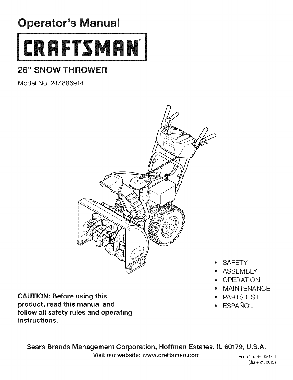
Operator's Manual
CRRFr MRN
26" SNOW THROWER
Model No. 247.886914
CAUTION" Before using this
product, read this manual and
follow all safety rules and operating
instructions.
Sears Brands Management Corporation, Hoffman Estates, IL 60179, U.S.A.
Visit our website: www.craftsman.com FormNo. 769-051341
,, SAFETY
o ASSEMBLY
OPERATION
MAINTENANCE
PARTS LIST
o ESPANOL
(June21,2013)
Page 2
WarrantyStatement.............................. Page2
SafeOperationPractices...................... Pages3-6
Assembly.................................... Pages8-13
Operation.................................. Pages14-17
Service&Maintenance....................... Pages18-23
CRAFTSMANTWOYEARFULLWARRANTY
FORTWOYEARSfromthedateofpurchase,thisproductiswarrantedagainstanydefectsinmaterialorworkmanship.Defectiveproductwillreceivefree
repairorfreereplacementif repairisunavailable.
ADDITIONALLIFETIMELIMITEDWARRANTYon UPPERand LOWERCHUTE
FORASLONGASITISUSEDbytheoriginalownerafterthesecondyearfromthedateofpurchase,theupperandlowerchuteofthissnowthrowerare
warrantedagainstanydefectsinmaterialorworkmanshipasverifiedbyaSearsauthorizedserviceprovider.Withproofofpurchase,youwill receiveanew
chutefreeofcharge.Youareresponsibleforthelaborcostofinstallationandanycostincurredtoverifythedefect.
Forwarrantycoveragedetailstoobtainrepairorreplacement,visitthewebsite:www.craftsman.com
ThiswarrantycoversONLYdefectsinmaterialandworkmanship.WarrantycoveragedoesNOTinclude:
• Expendableitemsthatcanwearoutfromnormalusewithinthewarrantyperiod,includingbutnotlimitedto augers,augerpaddles,driftcutters,skid
shoes,shaveplate,shearpins,sparkplug,aircleaner,belts,andoilfilter.
Off-SeasonStorage............................. Page24
Troubleshooting............................ Page26-27
PartsList................................... Pages28-47
RepairProtectionAgreement................... Page50
Espa_ol......................................... Page51
• Standardmaintenanceservicing,oilchanges,ortune-ups.
• Tirereplacementorrepaircausedbypuncturesfromoutsideobjects,suchasnails,thorns,stumps,orglass.
• Tireorwheelreplacementorrepairresultingfromnormalwear,accident,orimproperoperationormaintenance.
• Repairsnecessarybecauseofoperatorabuse,includingbutnotlimitedto damagecausedbyover-speedingtheengine,orfromimpactingobjectsthat
bendtheframe,augershaft,etc.
• Repairsnecessarybecauseofoperatornegligence,includingbutnotlimitedto,electricalandmechanicaldamagecausedbyimproperstorage,failureto
usethepropergradeandamountofengineoil,orfailuretomaintaintheequipmentaccordingtotheinstructionscontainedintheoperator'smanual.
• Engine(fuelsystem)cleaningorrepairscausedbyfueldeterminedtobecontaminatedoroxidized(stale).Ingeneral,fuelshouldbeusedwithin30days
ofitspurchasedate.
• Normaldeteriorationandwearoftheexteriorfinishes,orproductlabelreplacement.
Thiswarrantyisvoidifthisproductiseverusedwhileprovidingcommercialservicesorifrentedto anotherperson.
Thiswarrantygivesyouspecificlegalrights,andyoumayalsohaveotherrightswhichvaryfromstatetostate.
SearsBrandsManagementCorporation,NoffmanEstates,IL60179
Engine Oil: 5W-30
Fuel: Unleaded Gasoline
Engine: MTD
Model Number
Serial Number
Date of Purchase
Record the model number, serial number,
and date of purchase above.
© Sears Brands, LLC 2
Page 3
Thissymbolpointsout importantsafetyinstructionswhich, ifnot
followed,couldendangerthe personalsafetyand/orproperty of
yourselfandothers.Readandfollow all instructionsinthis manual
beforeattempting to operatethis machine.Failureto complywith these
instructionsmayresultinpersonalinjury.Whenyouseethis symbol, HEED
ITSWARNING!
Thismachinewasbuilt to beoperatedaccordingtothesafeoperation
practicesinthismanual.Aswith anytypeof powerequipment,
carelessnessorerroronthe part ofthe operatorcanresultinseriousinjury.
Thismachineiscapableof amputating fingers, hands,toesandfeet and
throwingdebris.Failuretoobservethefollowing safety instructionscould
resultinseriousinjuryor death.
CALIFORNIA PROPOSITION 65
EngineExhaust,someofits constituents,andcertainvehiclecomponents
containor emit chemicalsknowntoStateof Californiato causecancerand
birth defectsorother reproductiveharm.
TRAINING
Read,understand,andfollowall instructionsonthemachineandinthe
manual(s)beforeattemptingtoassembleandoperate.Failuretodosocan
resultinseriousinjurytotheoperatorand/orbystanders.Keepthis manual
inasafeplaceforfutureandregularreferenceandfororderingreplacement
parts.
Befamiliarwith allcontrolsandtheirproperoperation.Knowhowto stop
themachineanddisengagethemquickly.
Neverallowchildrenunder14yearsof agetooperatethismachine.Children
14andovershouldreadandunderstandtheinstructionsandsafeoperation
practicesinthismanualandonthemachineandbetrainedandsupervised
byanadult.
Neverallowadultsto operatethismachinewithoutproperinstruction.
Thrownobjectscancauseseriouspersonalinjury.Planyoursnow-throwing
patterntoavoiddischargeofmaterialtowardroads,bystandersandthelike.
Keepbystanders,petsandchildrenatleast75feetfromthemachinewhileit
isin operation.Stopmachineif anyoneentersthearea.
Exercisecautiontoavoidslippingorfalling,especiallywhenoperatingin
reverse.
PREPARATION
Thoroughlyinspecttheareawheretheequipmentistobeused.Removeall
doormats,newspapers,sleds,boards,wiresandotherforeignobjects,which
couldbetrippedoverorthrownbytheauger/impeller.
Alwayswearsafetyglassesoreyeshieldsduringoperationandwhile
performinganadjustmentor repairto protectyoureyes.Thrownobjects
whichricochetcancauseseriousinjurytotheeyes.
Donotoperatewithout wearingadequatewinteroutergarments.Donot
wearjewelry,longscarvesorotherlooseclothing,whichcouldbecome
entangledinmovingparts.Wearfootwearwhichwill improvefootingon
slipperysurfaces.
Useagroundedthree-wireextensioncordandreceptacleforallmachines
with electricstartengines.
Your Responsibility--Restrict theuseofthis powermachineto
personswhoread,understandandfollow the warningsand instructionsin
thismanualandonthe machine.
SAVETHESEINSTRUCTIONS!
Disengageallcontrolleversbeforestartingtheengine.
Adjustcollectorhousingheighttocleargravelorcrushedrocksurfaces.
Neverattempttomakeanyadjustmentswhileengineisrunning,except
wherespecificallyrecommendedintheoperator'smanual.
Letengineandmachineadjusttooutdoortemperaturebeforestartingto
clearsnow.
Safe Handling of Gasoline:
Toavoidpersonalinjuryor property damageuseextremecareinhandling
gasoline.Gasolineisextremely flammableandthevaporsareexplosive.
Seriouspersonalinjurycanoccurwhengasolineisspilledon yourselforyour
clotheswhichcanignite.Washyourskinandchangeclothesimmediately.
Useonlyanapprovedgasolinecontainer.
Neverfill containersinsideavehicleoronatruckortrailerbedwitha plastic
liner.Alwaysplacecontainersonthegroundawayfromyourvehiclebefore
filling.
Whenpractical,removegas-poweredequipmentfromthetruckor
trailerandrefuelitontheground.Ifthisis notpossible,thenrefuelsuch
equipmentonatrailerwith aportablecontainer,ratherthanfromagasoline
dispensernozzle.
Keepthenozzleincontactwith therimofthefueltankorcontaineropening
atalltimesuntilfuelingiscomplete.Donotusea nozzlelock-opendevice.
Extinguishallcigarettes,cigars,pipesandothersourcesofignition.
Neverfuelmachineindoors.
Neverremovegascaporaddfuelwhiletheengineishotorrunning.Allow
enginetocoolatleasttwominutesbeforerefueling.
Neveroverfill fueltank.Filltankto nomorethan1/2inchbelowbottomof
fillernecktoallowspacefor fuelexpansion.
Replacegasolinecapandtightensecurely.
Ifgasolineisspilled,wipeit offthe engineandequipment.Moveunitto
anotherarea.Wait.5minutesbeforestartingtheengine.
Page 4
Toreducefirehazards,keepmachinefreeofgrass,leaves,orotherdebris
build-up.Cleanupoilorfuelspillageandremoveanyfuelsoakeddebris.
Neverstorethemachineorfuelcontainerinsidewherethereisanopen
flame,sparkorpilotlightasonawaterheater,spaceheater,furnace,clothes
dryerorothergasappliances.
OPERATION
Donotputhandsorfeetnearrotatingparts,intheauger/impellerhousing
orchuteassembly.Contactwith therotatingpartscanamputatehandsand
feet.
Theauger/impellercontrolleverisasafetydevice.Neverbypassits
operation.Doingsomakesthemachineunsafeandmaycausepersonal
injury.
Thecontrolleversmustoperateeasilyin bothdirectionsandautomatically
returntothedisengagedpositionwhenreleased.
Neveroperatewith amissingordamagedchuteassembly.Keepallsafety
devicesinplaceandworking.
Neverrunanengineindoorsor inapoorlyventilatedarea.Engineexhaust
containscarbonmonoxide,anodorlessanddeadlygas.
Donotoperatemachinewhileundertheinfluenceofalcoholordrugs.
Mufflerandenginebecomehotandcancauseaburn.Donottouch.Keep
childrenaway.
Exerciseextremecautionwhenoperatingonorcrossinggravelsurfaces.Stay
alertforhiddenhazardsortraffic.
Exercisecautionwhenchangingdirectionandwhileoperatingonslopes.Do
notoperateonsteepslopes.
Planyoursnow-throwingpatterntoavoiddischargetowardswindows,
walls,carsetc.Thus,avoidingpossiblepropertydamageorpersonalinjury
causedbyaricochet.
Neverdirectdischargeatchildren,bystandersandpetsor allowanyonein
frontofthemachine.
Donotoverloadmachinecapacitybyattemptingtoclearsnowattoofastof
arate.
Neveroperatethismachinewithoutgoodvisibilityorlight.Alwaysbesureof
yourfootingandkeepafirmholdonthehandles.Walk,neverrun.
Disengagepowertotheauger/impellerwhentransportingornotin use.
Neveroperatemachineathightransportspeedsonslipperysurfaces.Look
downandbehindandusecarewhenbackingup.
Ifthemachineshouldstartto vibrateabnormally,stoptheengine,
disconnectthesparkplugwireandgrounditagainsttheengine.Inspect
thoroughlyfordamage.Repairanydamagebeforestartingandoperating.
Disengageallcontrolleversandstopenginebeforeyouleavetheoperating
position(behindthehandles).Waituntil theauger/impellercomesto
acompletestopbeforeuncloggingthechuteassembly,makingany
adjustments,orinspections.
Neverputyourhandin thedischargeorcollectoropenings.Donotunclog
chuteassemblywhileengineisrunning.Shutoff engineandremainbehind
handlesuntilallmovingpartshavestoppedbeforeunclogging.
Useonlyattachmentsandaccessoriesapprovedbythemanufacturer(e.g.
wheelweights,tirechains,cabsetc.).
Whenstartingengine,pull cordslowlyuntil resistanceisfelt,thenpull
rapidly.Rapidretractionofstartercord(kickback)will pullhandandarm
towardenginefasterthanyoucanletgo.Brokenbones,fractures,bruisesor
sprainscouldresult.
Ifsituationsoccurwhicharenotcoveredinthismanual,usecareandgood
judgment.
CLEARING A CLOGGED DISCHARGE CHUTE
Handcontactwith therotatingimpellerinsidethedischargechuteisthemost
commoncauseofinjuryassociatedwith snowthrowers.Neveruseyourhandto
cleanoutthedischargechute.
Toclearthechute:
a. SHUTTHEENGINEOFF!
b. Wait10secondsto besuretheimpellerbladeshavestopped
rotating.
c. Alwaysuseaclean-outtool,notyourhands.
MAINTENANCE & STORAGE
Nevertamperwith safetydevices.Checktheirproperoperationregularly.
Referto themaintenanceandadjustmentsectionsof thismanual.
Beforecleaning,repairing,orinspectingmachinedisengageallcontrol
leversandstoptheengine.Waituntiltheauger/impellercometoacomplete
stop.Disconnectthesparkplugwireandgroundagainsttheengineto
preventunintendedstarting.
Checkboltsandscrewsforpropertightnessatfrequentintervalsto keepthe
machineinsafeworkingcondition.Also,visuallyinspectmachineforany
damage.
Donotchangetheenginegovernorsettingorover-speedtheengine.The
governorcontrolsthemaximumsafeoperatingspeedof theengine.
Snowthrowershaveplatesandskidshoesaresubjecttowearanddamage.
Foryoursafetyprotection,frequentlycheckallcomponentsandreplace
with originalequipmentmanufacturer's(OEM)partsonlyaslistedinthe
Partspagesofthisoperator'smanual.Useofpartswhichdonotmeetthe
originalequipmentspecificationsmayleadtoimproperperformanceand
compromisesafety!
Checkcontrolleversperiodicallyto verifytheyengageanddisengage
properlyandadjust,if necessary.Referto theadjustmentsectioninthis
operator'smanualforinstructions.
Maintainorreplacesafetyandinstructionlabels,asnecessary.
Observeproperdisposallawsandregulationsforgas,oil,etc.toprotectthe
environment.
Priortostoring,runmachineafewminutestoclearsnowfrommachineand
preventfreezeupof auger/impeller.
Neverstorethemachineorfuelcontainerinsidewherethereisanopen
flame,sparkorpilotlight suchasawaterheater,furnace,clothesdryeretc.
Alwaysrefertotheoperator'smanualforproperinstructionsonoff-season
storage.
4
Page 5
Checkfuelline,tank,cap,andfittingsfrequentlyfor cracksor leaks.Replace
if necessary.
Donotcrankenginewith sparkplugremoved.
AccordingtotheConsumerProductsSafetyCommission(CPSC)andthe
U.S.EnvironmentalProtectionAgency(EPA),thisproducthasanAverage
Useful Lifeof seven(7)years,or60hoursofoperation.Attheendof
theAverage Useful Lifehavethemachineinspectedannuallybyan
authorizedservicedealerto ensurethat allmechanicalandsafetysystems
areworkingproperlyandnotwornexcessively.Failuretodosocanresultin
accidents,injuriesordeath.
DO NOT MODIFY ENGINE
Toavoidseriousinjuryordeath,donotmodifyengineinanyway. Tampering
with the governorsetting canleadto arunawayengineandcauseit to
operateat unsafespeeds.Nevertamperwith factorysetting ofengine
governor.
NOTICE REGARDING EMiSSiONS
Engineswhichare certifiedto complywith CaliforniaandfederalEPA
emissionregulationsfor SORE(SmallOff RoadEquipment)arecertified
tooperateonregularunleadedgasoline,and mayincludethefollowing
emissioncontrolsystems:EngineModification (EM),OxidizingCatalyst(0C),
SecondaryAirinjection(SAI)andThreeWayCatalyst(TWC)ifsoequipped.
SPARK ARRESTOR
e
Thismachineisequippedwith aninternalcombustionengineandshould
not beusedonornearanyunimprovedforest-covered,brushcoveredor
grass-coveredland unlesstheengine'sexhaustsystemisequippedwith a
sparkarrestormeetingapplicablelocalorstatelaws(if any).
Ira sparkarrestorisused,it shouldbemaintainedin effective working order
bythe operator.IntheStateof Californiathe aboveisrequiredbylaw (Section
4442ofthe CaliforniaPublicResourcesCode).Otherstatesmayhavesimilar
laws.Federallawsapplyonfederal lands.
Asparkarrestorfor the muffler is availablethroughyour nearestSearsParts
andRepairServiceCenter.
Page 6
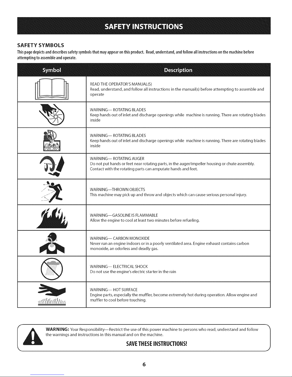
SAFETY SYMBOLS
Thispage depicts and describes safety symbols that may appear on this product. Read,understand, and follow all instructions on the machine before
attempting to assemble and operate.
READ THE OPERATOR'S MANUAL(S)
Read, understand, and follow all instructions in the manual(s) before attempting to assemble and
operate
WARNING-- ROTATING BLADES
Keep hands out of inlet and discharge openings while machine is running. There are rotating blades
inside
WARNING-- ROTATING BLADES
Keep hands out of inlet and discharge openings while machine is running. There are rotating blades
inside
WARNING-- ROTATING AUGER
Do not put hands or feet near rotating parts, in the auger/impeller housing or chute assembly.
Contact with the rotating parts can amputate hands and feet.
WARNING--THROWN OBJECTS
This machine may pick up and throw and objects which can cause serious personal injury.
WARNING--GASOLINE IS FLAMMABLE
Allow the engine to cool at least two minutes before refueling.
WARNING-- CARBON MONOXIDE
Never run an engine indoors or in a poorly ventilated area. Engine exhaust contains carbon
monoxide, an odorless and deadly gas.
WARNING-- ELECTRICAL SHOCK
Do not use the engine's electric starter in the rain
WARNING-- HOT SURFACE
Engine parts, especially the muffler, become extremely hot during operation. Allow engine and
muffler to cool before touching.
WARNING: Your Responsibility--Restrict the use of this power machine to persons who read, understand and follow
the warnings and instructions in this manual and on the machine.
SAVETHESEiNSTRUCTIONS!
6
Page 7

This page left intentionallyblank.
7
Page 8
NOTE:Referencestorightorleftsideofthesnowthroweraredeterminedfrom
behindtheunitin theoperatingposition(standingdirectlybehindthesnow
thrower,facingthehandlepanel).
Removing FromCarton
1. Cutthecornersofthecartonandlaythesidesflat ontheground.Remove
anddiscardallpackinginserts.
2. Movethesnowthroweroutofthecarton.
3. Makecertainthecartonhasbeencompletelyemptiedbeforediscardingit.
Assembly
Observethelowerrearareaof thesnowthrowerto besurebothcablesare
alignedwith rollerguidesbeforepivotingthehandleupward.
a. Placetheshift [everintheF6position.
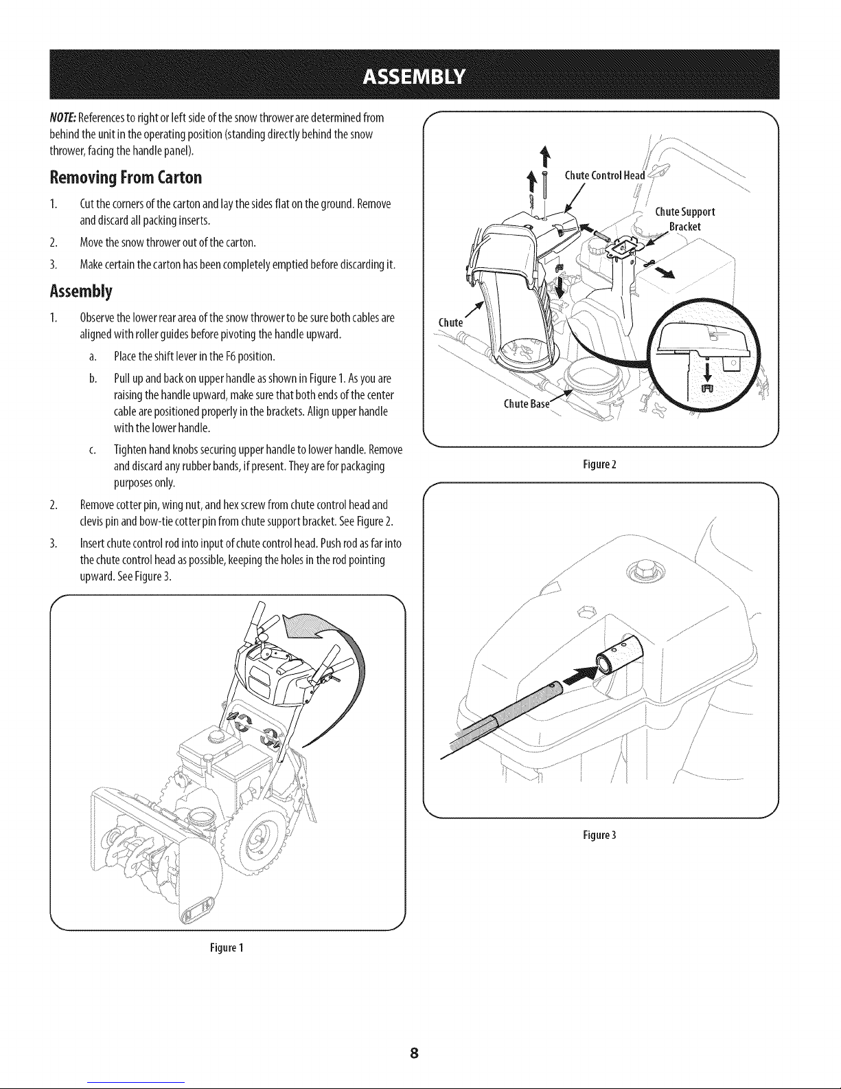
b. Pullupandbackonupperhandleasshownin Figure1.Asyouare
raisingthehandleupward,makesurethatbothendsofthecenter
cablearepositionedproperlyinthebrackets.Alignupperhandle
withthelowerhandle.
c. Tightenhandknobssecuringupperhandletolowerhandle.Remove
anddiscardanyrubberbands,if present.Theyarefor packaging
purposesonly.
Removecotterpin,wingnut,andhexscrewfromchutecontrolheadand
clevispinandbow-tiecotterpinfromchutesupportbracket.SeeFigure2.
Insertchutecontrolrodintoinputof chutecontrolhead.Pushrodasfarinto
thechutecontrolheadaspossible,keepingtheholesin therodpointing
upward.SeeFigure3.
f
ChuteSupport
Bracket
Chute
.J
Figure2
f
/ .....
Figure1
j
Rgure3
J
8
Page 9
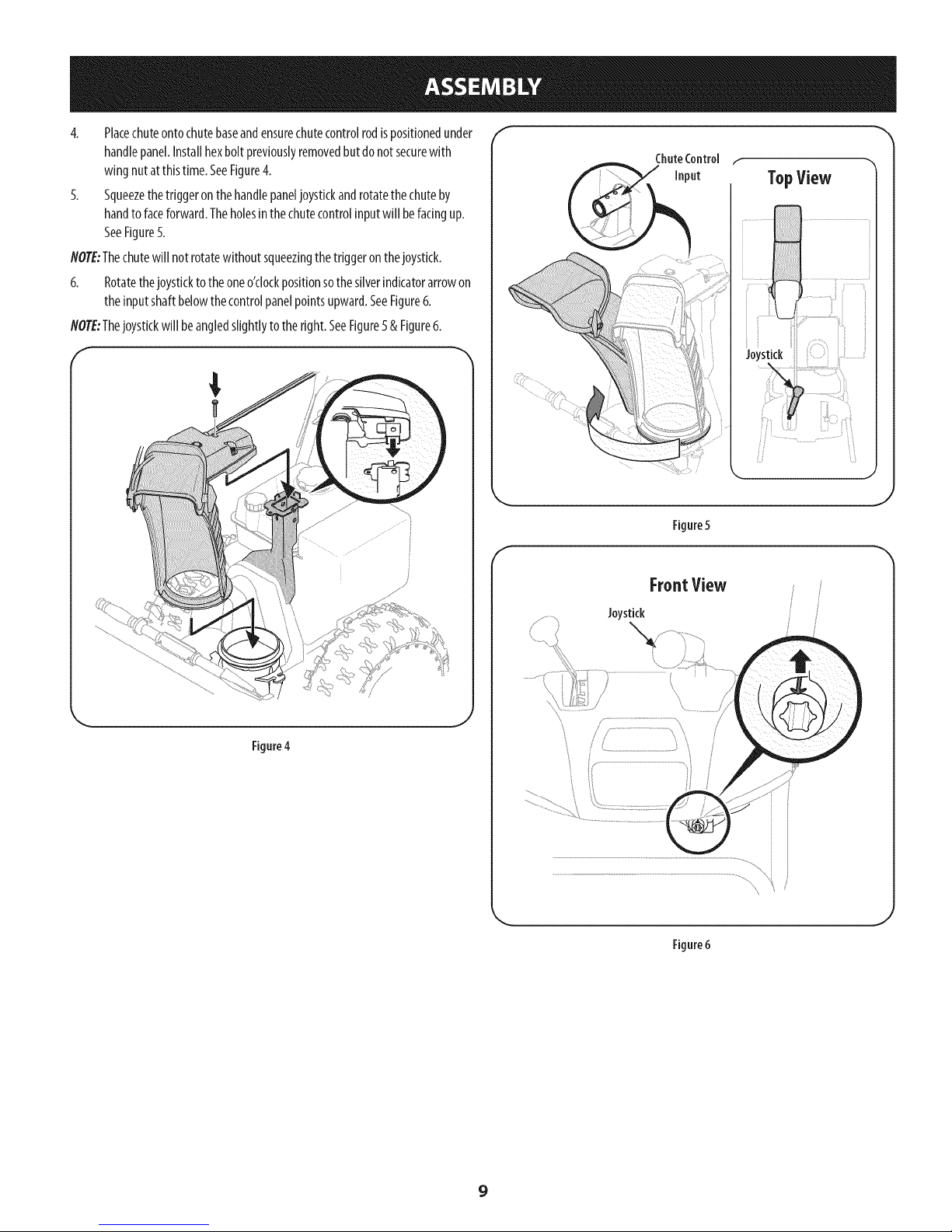
4. Placechuteontochutebaseandensurechutecontrolrodispositionedunder
handlepanel.Installhexboltpreviouslyremovedbutdonotsecurewith
wingnutat thistime.SeeFigure4.
5. Squeezethetriggeronthehandlepaneljoystickandrotatethechuteby
handtofaceforward.Theholesinthechutecontrolinputwillbefacingup.
SeeFigure5.
NOTE:Thechutewillnot rotatewithoutsqueezingthetriggeronthejoystick.
6. Rotatethejoysticktotheoneo'clockpositionsothesliverindicatorarrowon
theinputshaftbelowthecontrolpanelpointsupward.SeeFigure6.
NOTE:Thejoystickwill beangledslightlytotheright.SeeFigure5& Figure6.
f
TopView
_J
Figure5
f
FrontView
//f "_
Joystick
\
Figure6
9
Page 10
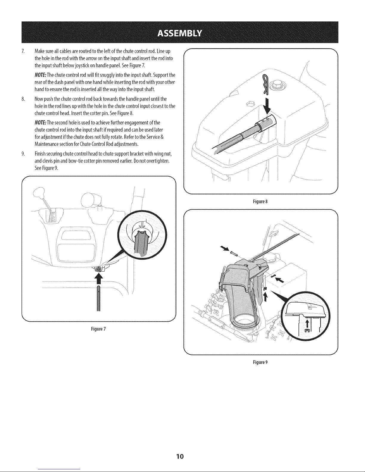
7. Makesureallcablesareroutedtotheleft ofthechutecontrolrod.Lineup
theholeintherodwiththearrowontheinputshaftandinserttherodinto
theinputshaftbelowjoystickonhandlepanel.SeeFigure7.
NOTE:Thechutecontrolrodwill fit snugglyintotheinputshaft.Supportthe
rearofthedashpanelwithonehandwhileinsertingtherodwith yourother
handtoensuretherodisinsertedallthewayintotheinputshaft.
8. Nowpushthechutecontrolrodbacktowardsthehandlepaneluntilthe
holeintherodlinesupwith theholeinthechutecontrolinputclosesttothe
chutecontrolhead.Insertthecotterpin.SeeFigure8.
NOTE:Thesecondholeisusedtoachievefurtherengagementof the
chutecontrolrodintotheinputshaftifrequiredandcanbeusedlater
foradjustmentifthechutedoesnotfully rotate.RefertotheService&
Maintenancesectionfor ChuteControlRodadjustments.
9. Finishsecuringchutecontrolheadto chutesupportbracketwith wingnut,
andclevispinandbow-tiecotterpinremovedearlier.Donotovertighten.
SeeFigure9.
f
f
/ /
Figure8
f
Figure7
\
Figure9
10
Page 11
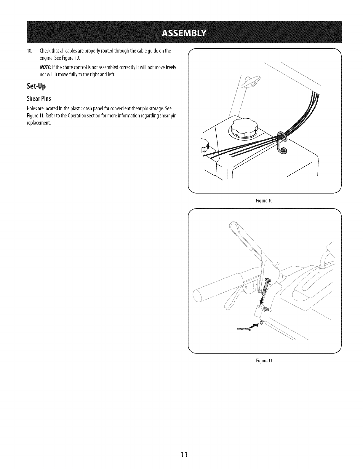
Checkthatallcablesareproperlyroutedthroughthecableguideonthe
engine.SeeFigure10.
NOTE:Ifthechutecontrolisnotassembledcorrectlyitwill notmovefreely
norwill it movefully totherightandleft.
Set-Up
ShearPins
Holesarelocatedintheplasticdashpanelforconvenientshearpinstorage.See
Figure11.RefertotheOperationsectionfor moreinformationregardingshearpin
replacement.
I
J
Figure10
f
J
Figure11
11
Page 12
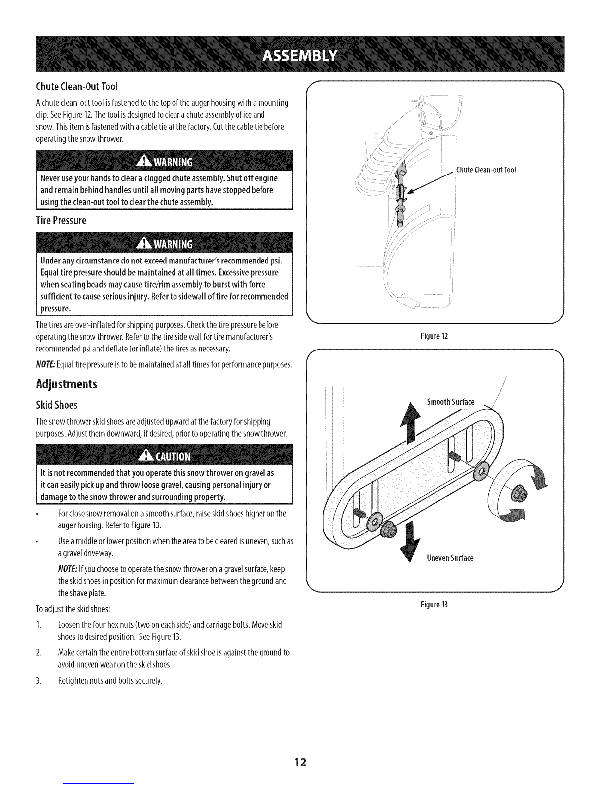
ChuteClean-OutTool f _
Achuteclean-outtoolisfastenedtothetopoftheaugerhousingwithamounting
clip.SeeFigure12.Thetoolisdesignedtoclearachuteassemblyoficeand
snow.Thisitemisfastenedwith acabletieat thefactory.Cutthecabletiebefore
operatingthesnowthrower.
ChuteClean-outTool
Neveruseyour handstoclearacloggedchuteassembly.Shutoff engine
andremainbehindhandlesuntil all movingpartshavestoppedbefore
usingthe clean-outtool to clearthe chuteassembly.
TirePressure
Underanycircumstancedo notexceedmanufacturer'srecommendedpsi.
Equaltire pressureshouldbemaintainedat alltimes. Excessivepressure
when seatingbeadsmaycausetireldm assemblyto burstwith force
sufficient tocauseseriousinjury. Refertosidewallof tire for recommended
pressure.
Thetiresareover-inflatedforshippingpurposes.Checkthetire pressurebefore
operatingthesnowthrower.Refertothetiresidewallfor tiremanufacturer's
recommendedpsianddeflate(orinflate)thetiresasnecessary.
NOTE:Equaltirepressureisto bemaintainedatalltimesforperformancepurposes.
Adjustments
SkidShoes
Thesnowthrowerskidshoesareadjustedupwardatthefactoryforshipping
purposes.Adjustthemdownward,ifdesired,priortooperatingthesnowthrower.
Itis notrecommendedthat youoperatethissnowthroweron gravelas
itcaneasilypickupandthrow loosegravel,causingpersonalinjuryor
damageto thesnowthrower andsurroundingproperty.
Forclosesnowremovalonasmoothsurface,raiseskidshoeshigheronthe
augerhousing.Referto Figure13.
Useamiddleorlowerpositionwhentheareatobeclearedisuneven,suchas
agraveldriveway.
NOTE:Ifyouchoosetooperatethesnowthroweronagravelsurface,keep
theskidshoesinpositionformaximumclearancebetweenthegroundand
theshaveplate.
Toadjusttheskidshoes:
1. Loosenthefourhexnuts(twooneachside)andcarriagebolts.Moveskid
shoestodesiredposition.SeeFigure13.
2. Makecertaintheentirebottomsurfaceofskidshoeisagainstthegroundto
avoidunevenwearontheskidshoes.
3. Retightennutsandboltssecurely.
///
.J
Figure12
f
SmoothSurface
UnevenSurface
\
Figure13
12
Page 13

AugerControl F
Priortooperatingyoursnowthrower,carefullyreadandfollowall
instructionsbelow.Performalladjustmentstoverifyyoursnowthroweris
operatingsafelyandproperly.
Checktheadjustmentoftheaugercontrolasfollows:
1. Theaugercontrolislocatedontheleft handle.SeeFigure14inset.When
theaugercontrolisreleasedandinthedisengaged"up"position,thecable
shouldhaveverylittle slack.ItshouldNOTbetight.
2. Ina well-ventilatedarea,startthesnowthrowerengine.Referto Starting
theEngineintheOperationsection.
3. Whilestandingintheoperator'sposition(behindthesnowthrower),engage
theauger.
4. Allowtheaugerto remainengagedforapproximatelyten(10)seconds
beforereleasingtheaugercontrol.Repeatthisseveraltimes.
5. Withtheaugercontrolinthedisengaged"up" position,walkto thefrontof
themachine.
6.
Toreadjustthecontrolcable,loosentheupperhexboltontheaugercable
bracket.SeeFigure14.
Positionthebracketupwardtoprovidemoreslack(ordownwardtoincrease
cabletension).
8. Retightentheupperhexbolt.
9. Repeatsteps2-6aboveto verifyproperadjustmenthasbeenachieved.
10. Confirmthat theaugerhascompletelystoppedrotatingandshowsNOsigns
ofmotion.IftheaugershowsANYsignsofrotating,immediatelyreturnto
theoperator'spositionandshutofftheengine.WaitforALLmovingpartsto
stopbeforeadjustingtheaugercontrol.
AugerControl
J
/
f
J
Figure14
13
Page 14
Chute Assembly
Clean Out
Tool
Drive Control
Gas Cap
Shift Lever
J
Four=WayChute ControP (Joystick)
J
Auger Control
\
MUfti\er i_e;:_lleStarte_
Primer
Key
Throttle
Control
Wheel Steering Control
IF ELLEVEL'
Choke
Control
/ Button
Oil Drain Electric Starter Outlet
Electric Start
Figure15
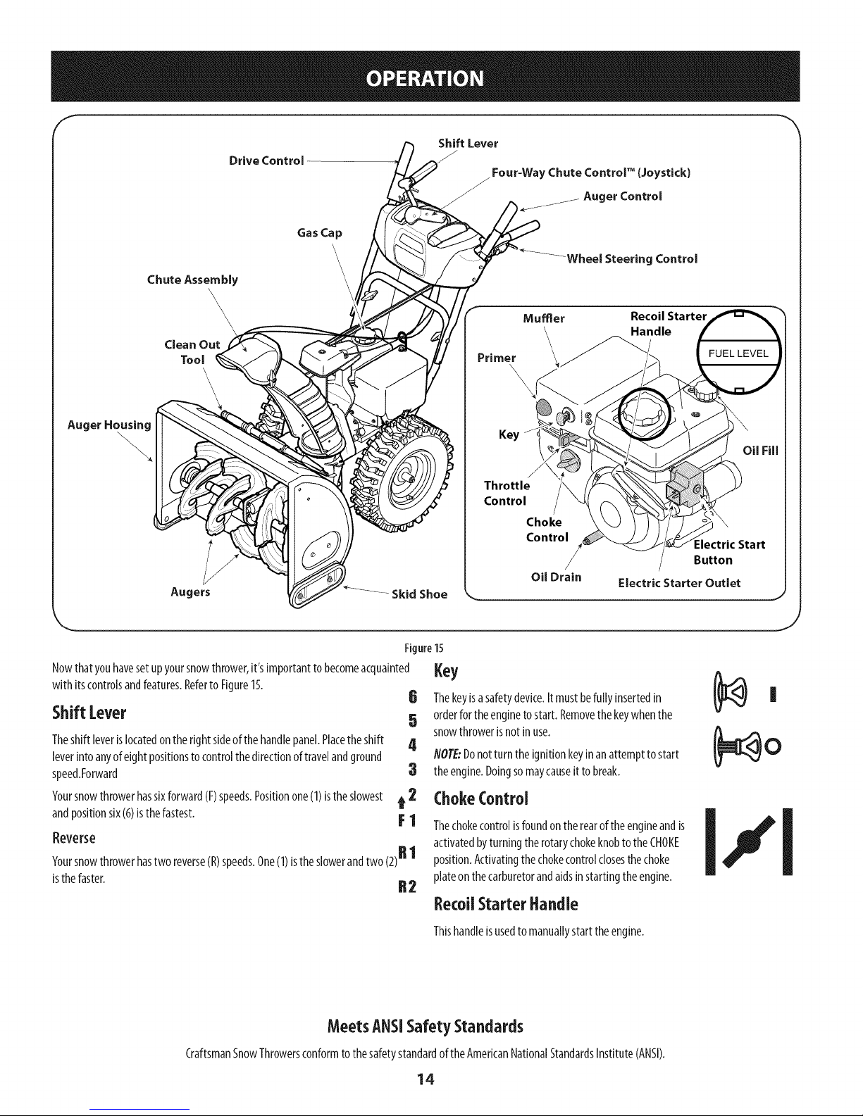
Nowthatyouhavesetupyoursnowthrower,it'simportanttobecomeacquainted
with itscontrolsandfeatures.Referto Figure15.
Shift [ever
Theshift leverislocatedontheright sideofthehandlepanel.Placetheshift
leverintoanyofeightpositionstocontrolthedirectionoftravelandground
speed.Forward
Yoursnowthrowerhassixforward(F)speeds.Positionone(1)isthe slowest
andpositionsix(6)isthefastest.
t 2 ChokeControl
Reverse
Yoursnowthrowerhastwo reverse(R)speeds.One(1)istheslowerandtwo(2)R 1
isthefaster. R2
MeetsANSiSafetyStandards
CraftsmanSnowThrowersconformtothesafetystandardoftheAmericanNationalStandardsInstitute(ANSI).
,ey6 Thekeyisasafetydevice.It mustbefully insertedin Ii
5 orderfortheenginetostart.Removethekeywhenthe
4 NOTE:Donotturntheignitionkeyinanattempttostart
snowthrowerisnotinuse. (_ O
:3 theengine.Doingsomaycauseitto break.
activated byturning the rotarychokeknobto the CHOKE
position.Activatingthe choke controlclosesthe choke
plateon the carburetorandaids instarting the engine.
RecoUStarterHandle
Thishandleisusedtomanuallystarttheengine.
14
Page 15
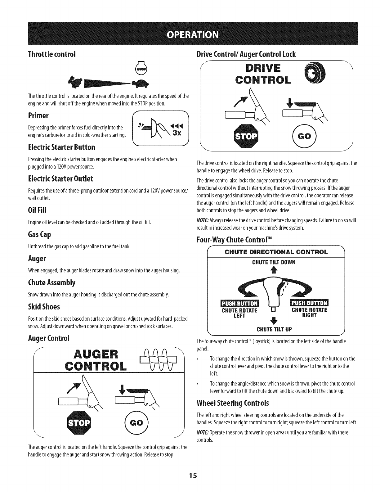
Throttlecontrol
Thethrottlecontrolislocatedontherearoftheengine.It regulatesthespeedofthe
engineandwillshutoffthe enginewhenmovedintotheSTOPposition.
Primer
Depressingtheprimerforcesfueldirectlyintothe
engine'scarburetortoaidincold-weatherstarting.
ElectricStarter Button
DriveControl/Auger Control Lock
/ DRIVE
CONTROL
Pressingtheelectricstarterbuttonengagestheengine'selectricstarterwhen
pluggedintoa 120Vpowersource.
ElectricStarter Outlet
Requirestheuseofathree-prongoutdoorextensioncordanda 120Vpowersource/
walloutlet.
OilFill
Engineoillevelcanbecheckedandoiladdedthroughtheoil fill.
GasCap
Unthreadthegascaptoaddgasolinetothefueltank.
Auger
Whenengaged,theaugerbladesrotateanddrawsnowintotheaugerhousing.
ChuteAssembly
Snowdrawnintotheaugerhousingisdischargedoutthechuteassembly.
SkidShoes
Positiontheskidshoesbasedonsurfaceconditions.Adjustupwardforhard-packed
snow.Adjustdownwardwhenoperatingongravelorcrushedrocksurfaces.
AugerControl
f
Thedrivecontrolislocatedontheright handle.Squeezethecontrolgripagainstthe
handletoengagethewheeldrive.Releasetostop.
Thedrivecontrolalsolockstheaugercontrolsoyoucanoperatethechute
directionalcontrolwithoutinterruptingthesnowthrowingprocess.Iftheauger
controlisengagedsimultaneouslywiththedrivecontrol,theoperatorcanrelease
theaugercontrol(ontheleft handle)andtheaugerswill remainengaged.Release
bothcontrolstostoptheaugersandwheeldrive.
flOTE:Alwaysreleasethedrivecontrolbeforechangingspeeds.Failuretodosowill
resultinincreasedwearonyourmachine'sdrivesystem.
Four-WayChuteControrM
CHUTe: DIRECTIONAL CONTROL
CHUTETILTDOWN
t
CHUTEROTATE CHUTEROTATE
LEFT RIGHT
CHUTETILTUP
_r n_
Thefour-waychutecontrolTM (Joystick)is locatedontheleft sideofthehandle
panel.
Tochangethedirectioninwhichsnowisthrown,squeezethebuttononthe
chutecontrolleverandpivotthechutecontrollevertotherightortothe
left.
Theaugercontrolislocatedontheleft handle.Squeezethecontrolgripagainstthe
handletoengagetheaugerandstartsnowthrowingaction.Releasetostop.
Tochangetheangle/distancewhichsnowisthrown,pivotthechutecontrol
leverforwardtotilt thechutedownandbackwardtotilt thechuteup.
Wheel Steering Controls
Theleft andrightwheelsteeringcontrolsarelocatedontheundersideofthe
handles.Squeezetherightcontroltoturnright;squeezetheleftcontroltoturn left.
NOTE:Operatethesnowthrowerinopenareasuntilyouarefamiliarwith these
controls.
15
Page 16
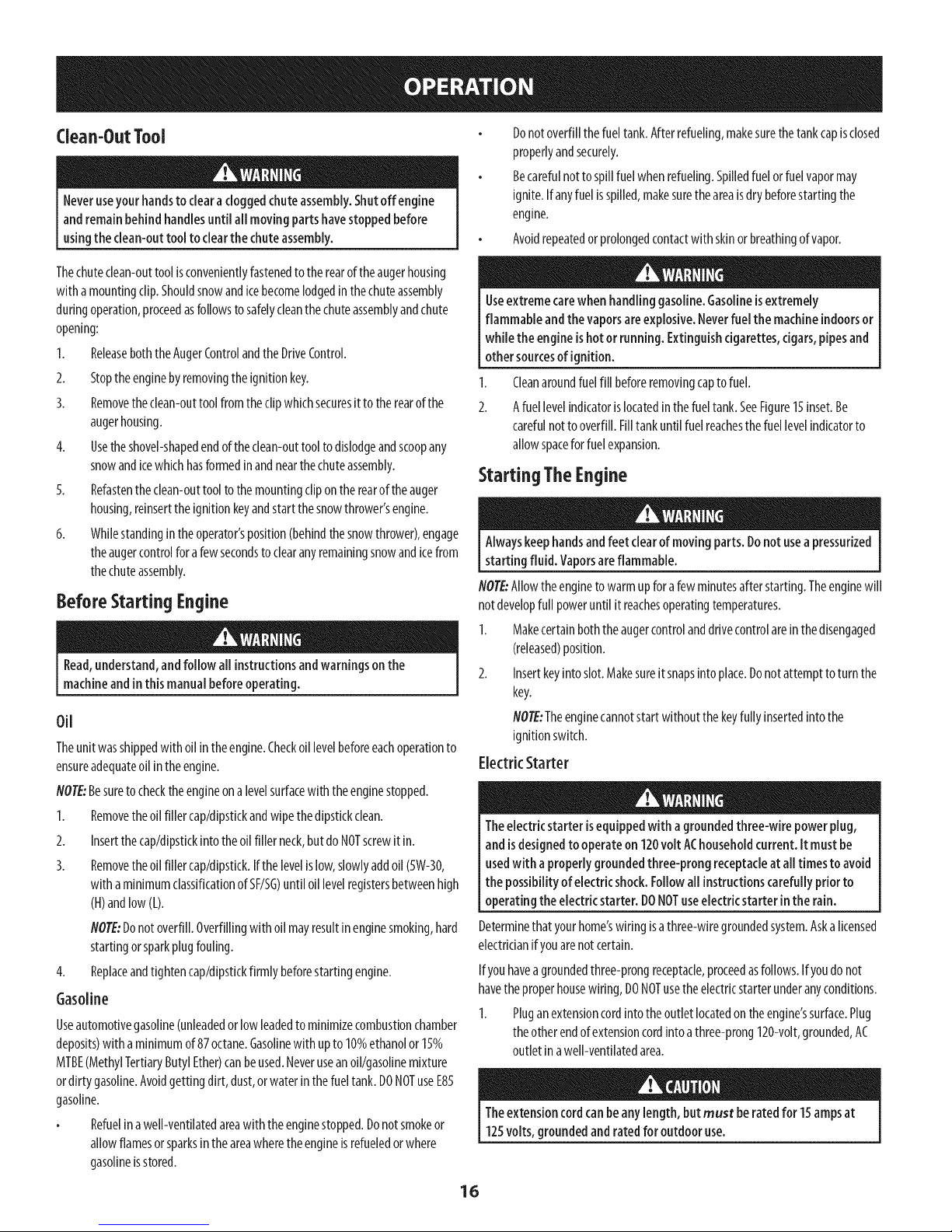
Clean-OutTool
Neveruseyour handstoclearacloggedchuteassembly.Shutoff engine
andremainbehindhandlesuntilall movingparts havestoppedbefore
usingthe clean-outtool to clearthe chuteassembly.
Thechutedean-outtoolisconvenientlyfastenedtotherearoftheaugerhousing
with amountingclip.Shouldsnowandicebecomelodgedin thechuteassembly
duringoperation,proceedasfollowstosafelycleanthechuteassemblyandchute
opening:
1. ReleaseboththeAugerControlandtheDriveControl.
2. Stoptheenginebyremovingtheignitionkey.
3. Removetheclean-outtoolfromtheclipwhichsecuresit totherearofthe
augerhousing.
4. Usetheshovel-shapedendoftheclean-outtooltodislodgeandscoopany
snowandicewhichhasformedinandnearthechuteassembly.
5. Refastentheclean-outtooltothemountingdipontherearoftheauger
housing,reinserttheignitionkeyandstartthesnowthrower'sengine.
6. Whilestandingintheoperator'sposition(behindthesnowthrower),engage
theaugercontrolforafewsecondstoclearanyremainingsnowandicefrom
thechuteassembly.
BeforeStartingEngine
Read,understand,andfollow all instructionsandwarningsonthe
machineandinthis manualbeforeoperating.
Oil
Theunitwasshippedwithoilintheengine.Checkoillevelbeforeeachoperationto
ensureadequateoilintheengine.
flO?E:Besuretochecktheengineonalevelsurfacewiththeenginestopped.
1. Removetheoilfillercap/dipstickandwipethedipstickclean.
2. Insertthecap/dipstickintotheoilfillerneck,butdoNOTscrewitin.
3. Removetheoilfillercap/dipstick.Ifthelevelislow,slowlyaddoil(5W-30,
with aminimumclassificationof SF/SG)untiloillevelregistersbetweenhigh
(H)andlow(L).
flOTE:Donotoverfill.Overfillingwithoilmayresultinenginesmoking,hard
startingorsparkplugfouling.
4.
Replaceandtightencap/dipstickfirmlybeforestartingengine.
Gasoline
Useautomotivegasoline(unleadedorlowleadedto minimizecombustionchamber
deposits)witha minimumof87octane.Gasolinewithupto 10%ethanolor15%
MTBE(MethylTertiaryButylEther)canbeused.Neveruseanoil/gasolinemixture
ordirtygasoline.Avoidgettingdirt, dust,orwaterinthefueltank.DONOTuseE85
gasoline.
Refuelinawell-ventilatedareawith theenginestopped.Donotsmokeor
allowflamesorsparksin theareawheretheengineisrefueledorwhere
gasolineisstored.
Donotoverfillthefueltank.Afterrefueling,makesurethetankcapisclosed
properlyandsecurely.
Becarefulnottospillfuelwhenrefueling.Spilledfuelorfuelvapormay
ignite.Ifanyfuelisspilled,makesuretheareaisdry beforestartingthe
engine.
Avoidrepeatedorprolongedcontactwithskinorbreathingofvapor.
Useextremecarewhenhandlinggasoline.Gasolineisextremely
flammableandthevaporsareexplosive.Neverfuel the machineindoorsor
while the engineishotor running. Extinguishcigarettes,cigars,pipesand
othersourcesof ignition.
1.
Cleanaroundfuelfill beforeremovingcaptofuel.
2.
Afuel levelindicatorislocatedinthefueltank.SeeFigure15inset.Be
carefulnottooverfill.Filltankuntil fuelreachesthefuellevelindicatorto
allowspacefor fuelexpansion.
Starting TheEngine
Alwayskeephandsandfeet clearof movingparts.Donot useapressurized
starting fluid. Vaporsareflammable.
flOTE:Allowtheengineto warmupfor afewminutesafterstarting.Theenginewill
notdevelopfull poweruntilit reachesoperatingtemperatures.
1. Makecertainboththeaugercontrolanddrivecontrolarein thedisengaged
(released)position.
2. Insertkeyintoslot.Makesureit snapsintoplace.Donotattempttoturnthe
key.
NOTE:Theenginecannotstartwithoutthekeyfullyinsertedinto the
ignitionswitch.
ElectricStarter
Theelectric starterisequippedwith agroundedthree-wirepowerplug,
andisdesignedtooperateon 120voltAChouseholdcurrent.It must be
usedwith aproperlygroundedthree-prongreceptacleatall timesto avoid
the possibilityof electrk shock.Followall instructionscarefullypriorto
operatingthe electricstarter. DONOTuseelectric starterinthe rain.
Determinethatyourhome'swring isathree-wiregroundedsystem.Askalicensed
electricianifyouarenotcertain.
Ifyouhavea groundedthree-prongreceptacle,proceedasfollows.Ifyoudonot
havetheproperhousewiring,DONOTusetheelectricstarterunderanyconditions.
1. Pluganextensioncordintotheoutletlocatedontheengine'ssurface.Plug
theotherendofextensioncordintoathree-prong120-volt,grounded,AC
outletinawell-ventilatedarea.
Theextensioncordcan beanylength, but must beratedfor 15ampsat
125volts,groundedand ratedforoutdoor use.
16
Page 17
2. Movethrottle controlto FAST(rabbit)_Jl__ position.
3 MovechoketotheCHOKEI,'Ipos t on co,deng nestart),fengine s
warm,placechokein RUNposition.
4. Pushprimerthree(3)times,makingsureto coverventholeinprimerbulb
whenpushing.Ifengineiswarm,pushprimeronlyonce.Alwayscovervent
holewhenpushing.Coolweathermayrequireprimingto berepeated.
5. Pushstarterbuttonto startengine.Oncetheenginestarts,immediately
releasestarterbutton.Electricstarterisequippedwith thermaloverload
protection;systemwilltemporarilyshut-downtoallowstartertocoolif
electricstarterbecomesoverloaded.
6.
Astheenginewarms,slowlyrotatethechokecontroltoRUNposition.Ifthe
enginefalters,restartengineandrunwith chokeathalf-chokepositionfora
shortperiodoftime,andthenslowlyrotatethechokeinto RUNposition.
Afterengineisrunning,disconnectextensioncordfromelectricstarter.
Whendisconnecting,alwaysunplugtheendatthewalloutletbefore
unpluggingtheoppositeendfromtheengine.
RecoilStarter
ToEngageDrive
1. Withthethrottlecontrolinthe Fast(rabbit)_ _1 position,moveshift lever
intooneofthesixforward(F)positionsortwo reverse(R)positions.Selecta
speedappropriatefor thesnowconditionsanda paceyou'recomfortable
with.
flOTE:WhenselectingaDriveSpeed,usetheslowerspeedsuntilyouare
comfortableandfamiliarwiththeoperationofthesnowthrower.
2. Squeezethedrivecontrolagainstthehandleandthesnowthrowerwill
move.Releaseit anddrivemotionwill stop.
NOTE:NEVERrepositiontheshiftlever(changespeedsordirectionoftravel)
withoutfirst releasingthedrivecontrolandbringingthesnowthrowertoa
completestop.Doingsowillresultinprematureweartothesnowthrower'sdrive
system.
ToEngageAuger
Toengagetheaugerandstartthrowingsnow,squeezetheaugercontrol
againstthelefthandle.Releaseto stoptheauger.
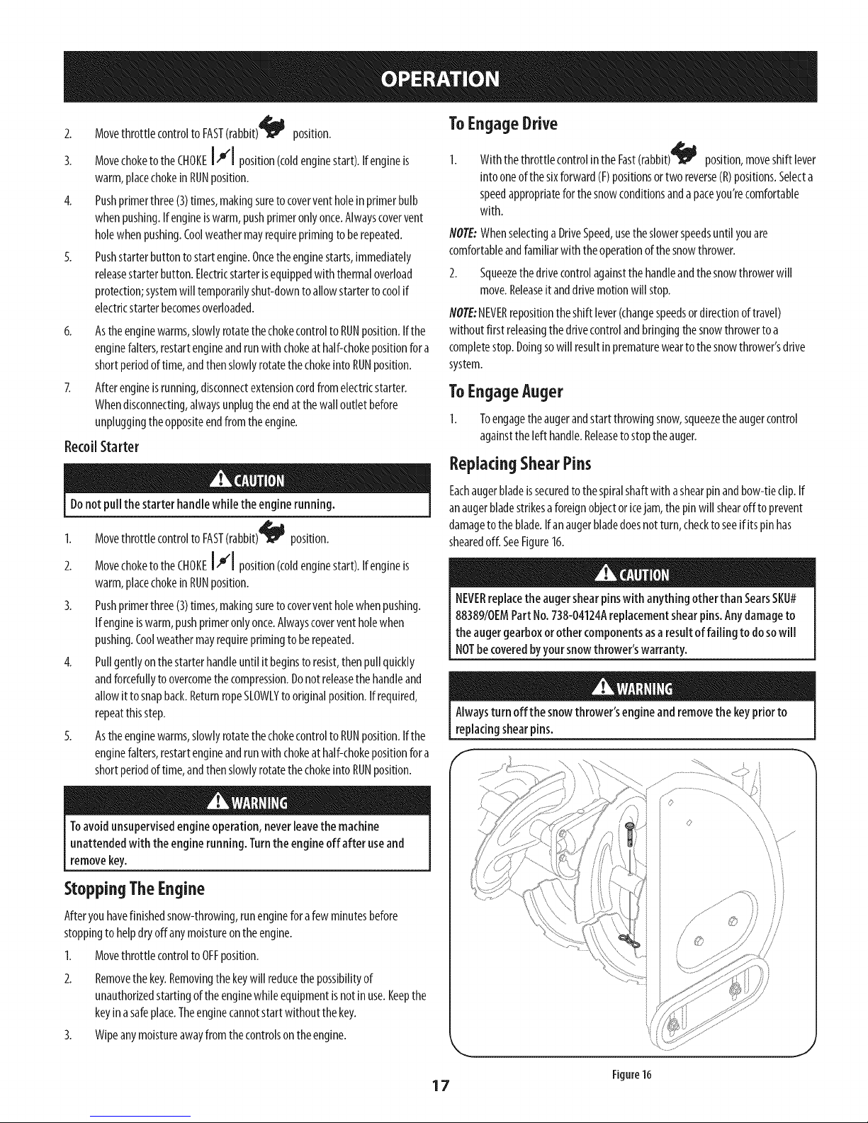
ReplacingShearPins
Eachaugerbladeissecuredtothespiralshaftwithashearpinandbow-tieclip.If
Donotpull the starter handlewhilethe enginerunning.
1. Movethrottle controlto FAST(rabbit)_ _j position.
2. Movechoketo theCHOKEI,*'1position(coldenginestart).If engineis
warm,placechokein RUNposition.
3. Pushprimerthree(3)times,makingsureto coverventholewhenpushing.
Ifengineiswarm,pushprimeronlyonce.Alwayscoverventholewhen
pushing.Coolweathermayrequireprimingtoberepeated.
4. Pullgentlyonthestarterhandleuntil it beginsto resist,thenpullquickly
andforcefullytoovercomethecompression.Donotreleasethe handleand
allowit tosnapback.ReturnropeSLOWLYto originalposition.If required,
repeatthisstep.
5. Astheenginewarms,slowlyrotatethechokecontroltoRUNposition.Ifthe
enginefalters,restartengineandrunwith chokeathalf-chokepositionfora
shortperiodoftime,andthenslowlyrotatethechokeinto RUNposition.
anaugerbladestrikesaforeignobjectoricejam,thepinwill shearoff toprevent
damagetotheblade.Ifanaugerbladedoesnotturn,checktoseeif itspinhas
shearedoff. SeeFigure16.
NEVERreplacetheaugershearpinswith anything otherthan SearsSKU#
88389/0EMPartNo.738-04124Areplacementshearpins.Anydamageto
the augergearboxorother componentsasaresultof failing to dosowill
NOTbecoveredbyyoursnowthrower'swarranty.
Alwaysturn off the snowthrower'sengineandremovethekeypriorto
replacingshearpins.
Toavoidunsupervisedengineoperation,neverleavethe machine
unattendedwith theenginerunning. Turntheengineoff after useand
removekey.
Stopping TheEngine
Afteryouhavefinishedsnow-throwing,runengineforafewminutesbefore
stoppingto helpdryoffanymoistureontheengine.
1. Movethrottle controlto OFFposition.
2. Removethekey.Removingthe keywillreducethepossibilityof
unauthorizedstartingoftheenginewhileequipmentisnotinuse.Keepthe
keyina safeplace.Theenginecannotstartwithoutthekey.
3. Wipeanymoistureawayfromthecontrolsontheengine.
17
J
Figure16
Page 18
MAINTENANCESCHEDULE
Beforeperforminganytypeof maintenance/service,disengageallcontrols
andstopthe engine.Wait until allmovingpartshavecometo a complete
stop.Disconnectsparkplug wireand grounditagainsttheengineto
preventunintendedstarting.
Followthemaintenanceschedulegivenbelow.Thischartdescribesservice
guidelinesonly.UsetheServiceLogcolumntokeeptrackofcompleted
maintenancetasks.TolocatethenearestSearsServiceCenterorto scheduleservice,
simplycontactSearsat1-800-4-MY-HOME®.
EachUseandevery5hours
Ist5hours
Annuallyor25hours
Annuallyor50hours
Annuallyor100hours
BeforeStorage
1. Engineoil level
2. Looseormissinghardware
3. Unitandengine.
1. Engineoil
1. Sparkplug
2. Controllinkagesandpivots
3. Wheels
4. GearshaftandAugershaft
5. 4-WayChuteControlTM
1. Engineoil
1. Sparkplug
1. Fuelsystem
EngineMaintenance
CheckingEngineOil
Beforelubricating, repairing,or inspecting,disengageall controlsandstop
engine.Waituntil all movingparts havecometo acompletestop.
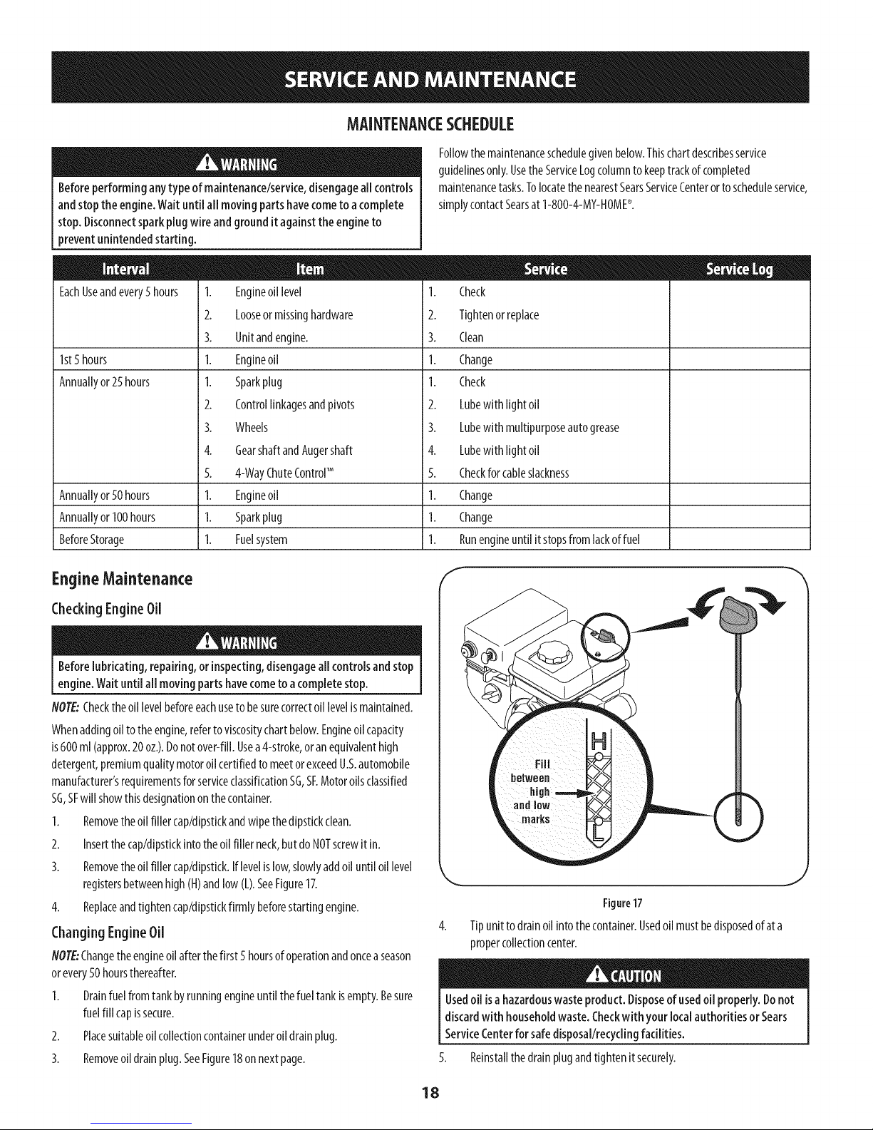
NOTE:Checktheoillevelbeforeeachuseto besurecorrectoillevelismaintained.
Whenaddingoiltotheengine,refertoviscositychartbelow.Engineoilcapacity
is600ml(approx.20oz.).Donotover-fill.Usea4-stroke,oranequivalenthigh
detergent,premiumqualitymotoroilcertifiedtomeetorexceedU.S.automobile
manufacturer'srequirementsforserviceclassificationSG,SF.Motoroilsclassified
SG,SFwillshowthisdesignationonthecontainer.
1. Removetheoilfillercap/dipstkkandwipethedipstkkclean.
2. Insertthecap/dipstkkintotheoilfillerneck,butdoNOTscrewit in.
3. Removetheoilfillercap/dipstick.Iflevelislow,slowlyaddoiluntiloillevel
registersbetweenhigh(H)andlow(L).SeeFigure17.
4. Replaceandtightencap/dipstickfirmlybeforestartingengine.
ChangingEngineOil
NOTE:Changetheengineoilafterthefirst5 hoursofoperationandoncea season
orevery50hoursthereafter.
1. Drainfuelfromtankbyrunningengineuntil thefueltankisempty.Besure
fuelfill capissecure.
2. Placesuitableoilcollectioncontainerunderoil drainplug.
3. Removeoildrainplug.SeeFigure18onnextpage.
1. Check
2. Tightenorreplace
3. Clean
1. Change
1. Check
2. Lubewith lightoil
3. Lubewith multipurposeautogrease
4. Lubewith lightoil
5. Checkfor cableslackness
1. Change
1. Change
1. Runengineuntilitstopsfromlackoffuel
f
J
Figure17
Tipunittodrainoil intothecontainer.Usedoil mustbedisposedof ata
propercollectioncenter.
Usedoil isahazardouswasteproduct.Disposeofusedoil properly.Donot
discardwith householdwaste.Checkwithyour localauthorities or Sears
ServiceCenterforsafedisposal/recyclingfacilities.
5. Reinstallthedrainplugandtightenitsecurely.
18
Page 19

Refillwith therecommendedoilandchecktheoil level.SeeRecommended
OilUsagechart.Theengine'soilcapacityis20ounces.
(oF)-40o-20 o 0o 20o 40o
(oc) -30° -20° -10° 0°
DONOTusenondetergentoil or 2-strokeengineoil. it couldshorten the
engine'sservicelife.
7. Reinstalltheoilfillercap/dipsticksecurely.
Thoroughlywashyour handswith soapandwater assoonaspossibleafter
handlingusedoil.
CheckingSparkPlug
OilDrain
Plug \
Figure18
E
SparkPlug
DONOTcheckforsparkwith sparkplugremoved.DONOTcrankenginewith
sparkplug removed.
Ifthe enginehasbeenrunning,the muffler will beveryhot. Becarefulnot
to touchthe muffler.
NOTE:Checkthe sparkplugonceaseasonor every25hoursofoperation.Change
thesparkplugonceaseasonorevery100hours.Toensureproperengineoperation,
thesparkplugmustbeproperlygappedandfreeofdeposits.
1. Removethesparkplugbootanduseasparkplugwrenchtoremovethe
plug.SeeFigure19.
2. Visuallyinspectthesparkplug.Discardthesparkplugifthereisapparent
wear,orif theinsulatoriscrackedorchipped.Cleanthesparkplugwitha
wirebrushifit istobereused.
3.
Measurethepluggapwith afeelergauge.Correctasnecessarybybending
sideelectrode.SeeFigure20.Thegapshouldbesetto.02-.03inches(0.60-
0.80mm).
4. Checkthatthesparkplugwasherisin goodconditionandthreadthespark
pluginbyhandtopreventcross-threading.
5. Afterthesparkplugisseated,tightenwithasparkplugwrenchtocompress
thewasher.
NOTE:Wheninstallinganewsparkplug,tighten1/2-turnafterthesparkplug
seatstocompressthewasher.Whenreinstallingausedsparkplug,tighten1/8-to
1/4-turnafterthesparkplugseatsto compressthewasher.
SparkPlugBoot
Figure19
Electrode
Thesparkplug mustbe tightened securely.Aloosesparkplugcanbecome
very hotandcandamagethe engine.
Figure20
19
Page 20
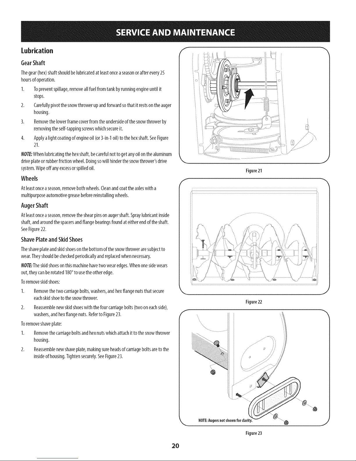
Lubrication "I
GearShaft
Thegear(hex)shaftshouldbelubricatedatleastonceaseasonorafterevery25
hoursofoperation.
I. Topreventspillage,removeallfuelfromtankbyrunningengineuntilit
stops.
2. Carefullypivotthesnowthrowerupandforwardsothatit restsontheauger
housing.
3. Removethelowerframecoverfromtheundersideofthesnowthrowerby
removingtheself-tappingscrewswhichsecureit.
4. Applyalightcoatingofengineoil(or3-in-1oil)to thehexshaft.SeeFigure
21.
NOTE:Whenlubricatingthe hexshaft,becarefulnottogetanyoilonthealuminum
driveplateorrubberfrictionwheel.Doingsowill hinderthesnowthrower'sdrive
system.Wipeoffanyexcessorspilledoil.
Wheels
Atleastonceaseason,removebothwheels.Cleanandcoattheaxleswitha
multipurposeautomotivegreasebeforereinstallingwheels.
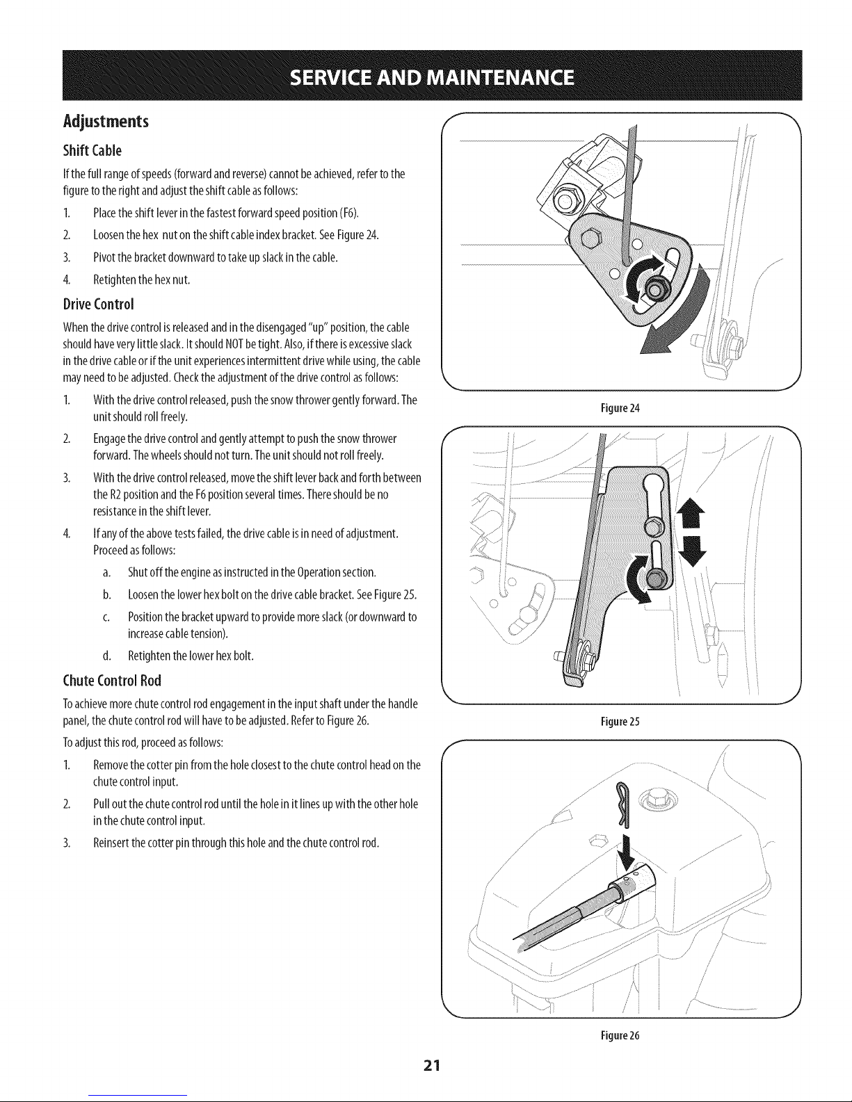
AugerShaft
Atleastonceaseason,removetheshearpinsonaugershaft.Spraylubricantinside
shaft,andaroundthespacersandflangebearingsfoundat eitherendoftheshaft.
SeeFigure22.
ShavePlateand SkidShoes
Theshaveplateandskidshoesonthebottomofthesnowthroweraresubjectto
wear.Theyshouldbecheckedperiodkallyandreplacedwhennecessary.
flOT£:Theskidshoesonthismachinehavetwo wearedges.Whenonesidewears
out,theycanberotated180°tousetheotheredge.
Toremoveskidshoes:
Removethetwocarriagebolts,washers,andhexflangenutsthatsecure
eachskidshoetothesnowthrower.
2. Reassemblenewskidshoeswith thefourcarriagebolts(twooneachside),
washers,andhexflangenuts.Referto Figure23.
Toremoveshaveplate:
1. Removethecarriageboltsandhexnutswhichattachittothesnowthrower
housing.
2. Reassemblenewshaveplate,makingsureheadsof carriageboltsaretothe
insideof housing.Tightensecurely.SeeFigure23.
f
J
Figure21
f
NOTE:Augersnot shownfor clarity.
Figure23
20
Page 21
Adjustments
Shift Cable
Ifthefull rangeofspeeds(forwardandreverse)cannotbeachieved,refertothe
figuretothefight andadjusttheshiftcableasfollows:
I. Placetheshift leverinthefastestforwardspeedposition(F6).
2. Loosenthehex nutontheshiftcableindexbracket.SeeFigure24.
3. Pivotthebracketdownwardtotakeupslackinthecable.
4. Retightenthehexnut.
DriveControl
Whenthedrivecontrolisreleasedandinthedisengaged"up"position,thecable
shouldhaveverylittle slack.ItshouldNOTbetight. Also,ifthereisexcessiveslack
inthedrivecableor iftheunitexperiencesintermittentdrivewhileusing,thecable
mayneedtobeadjusted.Checktheadjustmentofthedrivecontrolasfollows:
I. Withthedrivecontrolreleased,pushthesnowthrowergentlyforward.The
unitshouldrollfreely.
2. Engagethedrivecontrolandgentlyattemptto pushthesnowthrower
forward.Thewheelsshouldnotturn.Theunitshouldnotrollfreely.
3. Withthedrivecontrolreleased,movetheshift leverbackandforthbetween
theR2positionandtheF6positionseveraltimes.Thereshouldbeno
resistanceintheshiftlever.
f
Figure24
4. Ifanyoftheabovetestsfailed,thedrivecableisinneedofadjustment.
Proceedasfollows:
a. Shutoff theengineasinstructedinthe Operationsection.
b. Loosenthelowerhexboltonthedrivecablebracket.SeeFigure25.
c. Positionthebracketupwardto providemoreslack(ordownwardto
increasecabletension).
d. Retightenthelowerhexbolt.
ChuteControlRod
Toachievemorechutecontrolrodengagementintheinputshaftunderthe handle
panel,thechutecontrolrodwill havetobeadjusted.RefertoFigure26.
Toadjustthisrod,proceedasfollows:
I. Removethecotterpinfromtheholeclosesttothechutecontrolheadonthe
chutecontrolinput.
2. Pulloutthechutecontrolroduntiltheholeinit linesupwith theotherhole
inthechutecontrolinput.
3. Reinsertthecotterpinthroughthisholeandthechutecontrolrod.
Figure25
"',,,%
............................/ ....
21
Figure26
/
/
/
/
/
/
Page 22
AugerControl
RefertotheAssemblysectionforinstructionsonadjustingtheaugercontrolcable.
SkidShoes
RefertotheAssemblysectionforinstructionsonadjustingtheskidshoes.
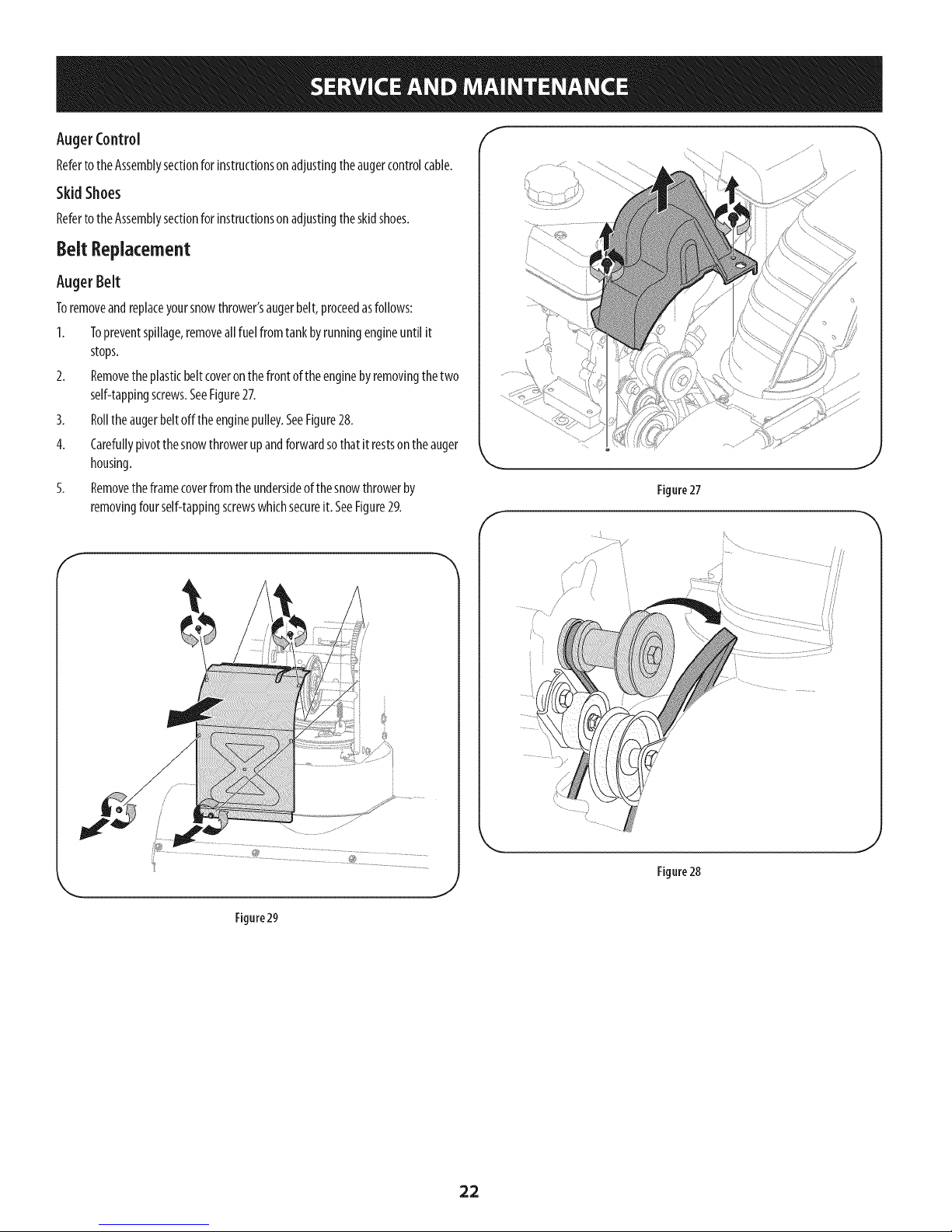
Belt Replacement
Auger Belt
Toremoveandreplaceyoursnowthrower'saugerbelt,proceedasfollows:
I. Topreventspillage,removeallfuelfromtankbyrunningengineuntilit
stops.
2. Removetheplasticbeltcoveronthefrontof theenginebyremovingthetwo
self-tappingscrews.SeeFigure27.
3. Rolltheaugerbeltoffthe enginepulley.SeeFigure28.
4. Carefullypivotthesnowthrowerupandforwardsothatit restsontheauger
housing.
5. Removetheframecoverfromtheundersideofthesnowthrowerby
removingfourself-tappingscrewswhichsecureit. SeeFigure29.
f
J
Figure27
Figure29
J
22
Page 23
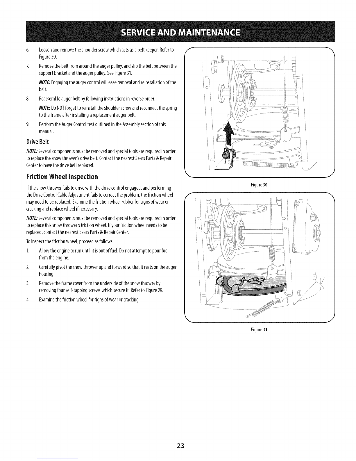
Loosenandremovetheshoulderscrewwhichactsasabeltkeeper.Referto
Figure30.
Removethebeltfromaroundtheaugerpulley,andslipthebeltbetweenthe
supportbracketandtheaugerpulley.SeeFigure31.
NOTE:Engagingtheaugercontrolwill easeremovalandreinstallationof the
belt.
8.
Reassembleaugerbeltbyfollowinginstructionsinreverseorder.
NOTE:DoNOTforgettoreinstalltheshoulderscrewandreconnectthespring
totheframeafterinstallingareplacementaugerbelt.
PerformtheAugerControltestoutlinedintheAssemblysectionofthis
manual.
Drive Belt
NOTE:Severalcomponentsmustberemovedandspecialtoolsarerequiredinorder
toreplacethesnowthrower'sdrivebelt.ContactthenearestSearsParts& Repair
Centerto havethedrivebeltreplaced.
FrictionWheelInspection
Ifthesnowthrowerfailstodrivewiththedrivecontrolengaged,andperforming
theDriveControlCableAdjustmentfailstocorrectthe problem,thefrictionwheel
mayneedtobereplaced.Examinethefrictionwheelrubberforsignsofwearor
crackingandreplacewheelifnecessary.
NOTE:Severalcomponentsmustberemovedandspecialtoolsarerequiredin order
toreplacethissnowthrower'sfrictionwheel.Ifyourfrictionwheelneedsto be
replaced,contactthe nearestSearsParts& RepairCenter.
Toinspectthefrictionwheel,proceedasfollows:
1. Allowtheengineto rununtil itisoutof fuel.Donotattemptto pourfuel
fromtheengine.
2. Carefullypivotthesnowthrowerupandforwardsothatit restsontheauger
housing.
3. Removetheframecoverfromtheundersideofthesnowthrowerby
removingfourself-tappingscrewswhichsecureit. Referto Figure29.
4. Examinethefrictionwheelforsignsofwearorcracking.
J
Figure30
Figure31
23
Page 24
Ifthesnowthrowerwill notbeusedfor 30daysorlonger,orifit istheendofthesnowseasonwhenthelastpossibilityofsnowisgone,theequipmentneedsto bestored
properly.Followstorageinstructionsbelowtoensuretopperformancefromthesnowthrowerformanymoreyears.
PreparingEngine
Enginesstoredover30daysneedtobedrainedoffueltopreventdeteriorationand
gumfromforminginfuelsystemoronessentialcarburetorparts.Ifthegasolinein
yourenginedeterioratesduringstorage,youmayneedtohavethecarburetor,and
otherfuelsystemcomponents,servicedorreplaced.
1. Removeallfuelfromtankbyrunningengineuntil it stops.Donotattemptto
pourfuelfromtheengine.
2. Changetheengineoil.
3. Removesparkplugandpourapproximately1oz.(30ml)ofcleanengineoil
intothecylinder.Pulltherecoilstarterseveraltimestodistributetheoil, and
reinstallthesparkplug.
4. Cleandebrisfromaroundengine,andunder,around,andbehindmuffler.
Applyalightfilm ofoilonanyareasthat aresusceptibleto rust.
Storeinaclean,dryandwellventilatedareaawayfromanyappliancethat
operateswith aflameorpilot light,suchasafurnace,waterheater,or
clothesdryer.Avoidanyareawitha sparkproducingelectricmotor,orwhere
powertoolsareoperated.
Neverstoresnowthrowerwith fuel intank indoorsorin poorlyventilated
areas,wherefuelfumesmayreachanopenflame,sparkor pilotlight ason
afurnace,water heater,clothesdryeror gasappliance.
PreparingSnowThrower
Whenstoringthe snowthrowerin anunventilatedormetalstorageshed,
careshouldbetakento rustprooftheequipment.Usinga lightoilorsilicone,
coattheequipment,especiallyanychains,springs,bearingsandcables.
Removealldirt fromexteriorofengineandequipment.
Followlubricationrecommendations.
Storeequipmentinaclean,dryarea.
InflatethetirestothemaximumPSI.Refertotire sidewall.
Ifpossible,avoidstorageareaswith highhumidity.
Keeptheenginelevelinstorage.Tiltingcancausefueloroil leakage.
24
Page 25

25
Page 26

Disconnectthe sparkplugwireandgrounditagainstthe engineto prevent
unintendedstarting. Beforeperforminganytypeofmaintenance/service,
disengageallcontrolsandstoptheengine.Waituntil aHmovingparts
havecometoa completestop.Alwayswear safetyglassesduringoperation
or while performinganyadjustmentsorrepairs.
Thissectionaddressesminorserviceissues.Tolocatethe nearestSearsServiceCenterorto scheduleservice,simplycontactSearsat1-800-4-MY=HOMP.
Engine fails to start 1.
Engine running erratically/
inconsistent RPM (hunting
or surging)
Excessive vibration
Lossof power
Unit fails to propel itself
Choke control not in CHOKE position.
2.
Spark plug wire disconnected.
3.
Faulty spark plug.
4.
Fuel tank empty or stale fuel.
5.
Engine not primed.
6.
Key not inserted.
7.
Extension cord not connected (when
using electric start button, on models so
equipped).
1. Engine running on CHOKE.
2. Stale fuel.
3. Water or dirt in fuel system.
4. Carburetor out of adjustment.
5. Over-governed engine.
1. Loose parts or damaged auger.
1. Spark plug wire loose.
2. Gas cap vent hole plugged.
1. Drive cable in need of adjustment.
2. Drive belt loose or damaged.
3. Worn friction wheel.
1. Move choke control to CHOKE position.
2. Connectwire to spark plug.
3. Clean, adjust gap, or replace.
4. Fill tank with clean, fresh gasoline.
5. Prime engine as instructed in the Operation Section.
6. Insert key fully into the switch.
7. Connect one end of the extension cord to the
electric starter outlet and the other end to a three-
prong 120-volt, grounded, ACoutlet.
1. Move choke control to RUN position.
2. Fill tank with clean, fresh gasoline.
3. Drain fuel tank by running engine until it stops. Refill
with fresh fuel.
4.
Contact your Sears Parts & Repair Center.
5.
Contact your Sears Parts & Repair Center.
1.
Stop engine immediately and disconnect spark
plug wire. Tighten all bolts and nuts. If vibration
continues, have unit serviced by a Sears Parts &
Repair Center.
1.
Connect and tighten spark plug wire.
2.
Remove ice and snow from gas cap. Be certain vent
hole is clear.
1.
Adjust drive control cable. Refer to Service and
Maintenance section.
2.
Have drive belt replaced. Contact your Sears Parts &
Repair Center.
3.
Have friction wheel replaced at a Sears Parts &
Repair Center.
NEED MORE HELP?
Find this and a[[ your other product manuals online,
Get answers from our team of home experts.
Get a personalized maintenance plan for your home.
Find information and tools to help Mth home projects.
26
Page 27

Unit fails to discharge snow
1. Chute assembly clogged. 1. Stop engine immediately and disconnect spark
plug wire. Clean chute assembly and inside of auger
housing with clean-out tool or a stick.
2. Foreign object lodged in auger.
2. Stop engine immediately and disconnect spark plug
wire. Remove object from auger with clean-out tool
or a stick.
3. Auger cable in need of adjustment.
3. Adjust auger control cable. Refer to Assembly
section.
4. Auger belt loose or damaged.
4. Replace auger belt. Refer to Service and
Maintenance section.
5. Shearpin(s) sheared.
5. Replace with new shear pin(s).
Chute fails to easily rotate
180 degrees
1. Chuteassembled incorrectly.
1. Disassemble chute control and reassemble as
directed in the Assembly section.
NEED MORE HELP?
YotJU,fir_}the _: swe a_] :m,_"Yeo_:__._a_,a_emy[f_eo_@_,,,,,,,fo_'free!
o Find this and a[[ your other product manuals online.
Get answers from our team of home experts,
o Get a personalized maintenance plan for your home_
Find information and tools to help with home projects.
27
Page 28

CraftsmanSnowThrower Model247.886914
15
20
17
31
54
' 32
10j_
i27
28
Page 29

CraftsmanSnowThrowerModel 247.886914
N
1.
2.
3.
4.
5.
6.
7.
8.
9.
10.
11.
12.
13.
14.
15.
16.
17.
18.
19.
20.
21.
22.
23.
24.
25.
26.
27.
731-2635
684-04057A-0637
710-0347
710-0451
710-04484
710-0703
712-04063
712-04064
712-04065
714-04040
936-0159
926-04012
731-07525
732-04460
736-0174
736-0242
946-04230A
931-2643
738-0143
938-0281
738-04124A
941-0245
941-0309
756-04224
790-00075
790-00080A-0637
918-04172B
Snow Removal Tool Mount
Impeller Assembly, 12" Dia.
Hex Screw, 3/8-16, 1.75, Gr5
Bolt, Carriage, 5/16-18, .750 Grl
Screw, 5/16-18, 0.750
Screw, Carriage, 1/4-20, .750, Gr5
Nut, Flange Lock, 5/16-18, Nylon
Nut, Flange Lock, 1/4-20, Nylon
Nut, Flange Lock, 3/8-16, Nylon
Cotter Pin, Bow-tie
Washer, Flat, .349 x .879 x .063
Nut, Push-on, .25 Dia
Chute, Adapter 5" Dia
Spring, Extension, .38 OD x 4.59
Washer, Wave, .625 x .885 x .015
Washer, Bell, .340 x .872 x .060
Clutch Cable, Auger, 47.23"
Snow Removal Tool
Screw, Shoulder, .498 x .34, 3/8-16
Screw, Shoulder, .625 x .17, 3/8-16
Shear Pin, .25 x 1.50
Bearing, Hex Flange x .75 ID
Bearing, Ball, .75 ID x 1.85 OD
Flat Pulley, Idler, 2.75 OD
Housing, Bearing, 1.85 ID
Bracket, Auger Idler w/Brake
Gearbox Assembly, Auger, 26"
m
28.
29.
30.
31.
32.
33.
34.
35.
36.
37.
38.
39.
40.
41.
42.
43.
44.
45.
46.
47.
48.
49.
50.
51.
52.
53.
54.
684-04264-4044
684-04107-0637
684-04108-0637
731-04870
736-0188
741-0493A
790-00087A-0637
790-00121-4044
731-05984A
918-0123A
918-0124A
921-0338
741-0662
710-0642
711-04284
914-0161
715-04021
917-04126
917-04861
718-04071
721-0325
721-0327
936-0351
736-3084
741-0663
741-0661 B
710-0276
Housing Assembly, Auger 26"
Spiral Assembly, LH
Spiral Assembly, RH
Spacer, 1.25 OD x .75 ID x 1.00
Washer, Flat, .76 x 1.49 x .06
Bushing, Flange, .80 ID x .91 OD
Housing, I" Hex Bearing
Shave Plate, 2.25 x 25.66
Slide Shoe
Housing, Auger, RH Reduced
Housing, Auger, LH Reduced
Seal, Oil, .750 x 1.00 x .125
Bearing, Flange, .75 x 1.0 x .59
Screw, Self-tapping, I/4-20, 0.750
Axle, Auger, 26"
Key, Hi-pro 3/16 x 5/8
Pin, Dowel, .25 OD x 1.2
Shaft, Worm .75 OD
Gear, Worm 20T
Collar, Thrust
Plug, I/4 x .437
Seal, Oil, .75 x I x .131
Washer, Flat, .760 ID x 1.50D
Washer, Flat, .51 x 1.12
Bearing, Flange, .75 x 1.0 x .925
Bearing, Flange, .75 x 1.00 x .975
Screw, Carriage, 5/16-18 x 1.00
29
Page 30

CraftsmanSnowThrower Model247.886914
27
/
15 ///
/
/
/
/
27
1
/
/
28
f
30
29
3O
Page 31

CraftsmanSnowThrower Model247.886914
1.
2.
3.
4.
5.
6.
7.
8.
9.
10.
11.
12.
13.
14.
15.
16.
17.
18.
19.
20.
21.
22.
23.
24.
25.
26.
27.
28.
29.
30.
31.
32.
33.
34.
35.
36.
3Z
± Available for warranty coverage only. Contact a Sears authorized
service provider for details.
984-04338A
710-04187
715-0150
747-05116
710-04370
738-04367
918-04801A
736-04446
920-0284
936-0159
731-04427A
914-0101
711-04469A
712-3087
684- 0431IA-0637
714-04040
712-04064
712-04063
784-5594-0637
731-06451
710-0262
710-0895
710-04071
731-06440A
710-0627
946-04528A
946-04477
753-06151
731-04893A
710-04879
710-04353
731-07031
984-04324A
753-06152
753-06153
710-1256
684-04350
715-04095
753-08018f
4-Way Chute Control TM Assembly
Hi-Lo Screw, 1/4-15 x 0.5
Roll Pin
Chute Rod
Hex Screw, 1/4-20 x 3.00
Flange Shoulder Screw
4-Way Chute Gearbox Assembly
Flat Washer, .25 x .630 x .0515
Wing Knob
Flat Washer, .349 x .879 x .063
Upper Chute
Cotter Pin
Clevis Pin
Wing Nut, 1/4-20
Chute Support Bracket
Bow Tie Cotter Pin
Flange Lock Nut, 1/4-20
Flange Lock Nut, 5/16-18
Cable Bracket
Chute Tilt Cable Guide
Carriage Bolt, 5/16-18 x 1.50
Hi-Lo Screw, 1/4-15 x .75
Carriage Bolt, 5/16-18 x 1.0
Lower Chute
Hex Screw, 5/16-24 x .750
4-Way Cable
4-Way Cable w/Clip (Not Shown)
Handle Assembly
Handle Plunger
Screw, Mach., #8-32 x .750
Screw, #8 x 1.00
Handle Lever
Shift Assembly
Gear Set Assembly
Handle Housing Assembly
Screw, #8-18 x 1.250
Joint Block Assembly
Pin
Chute Kit (Incl. Ref.# 11 & 24)
31
Page 32

CraftsmanSnowThrower Model247.886914
12
2
3
31
/
61/_
32
Page 33

CraftsmanSnowThrowerModel247.886914
M
1.
2.
3.
4.
5.
6.
7.
8.
9.
10.
11.
12.
13.
14.
15.
16.
17.
18.
19.
20.
21.
22.
23.
24.
25.
26.
27.
28.
29.
30.
31.
32.
33.
34.
35.
684-04112C
732-04238
731-04894D
684-04250
935-0199A
710-3069
731-04896B
712-04081A
684- 04111 B
631-04133A
720-0274
710-1233
738-04348
710-04586
749-04190A-0637
710-0572
720-04039
753-06437
731-05324
731-06113
631-04134B
725-0157
712-04064
732-0193
790-00311B-0637
790-00248C-0637
738-04125
920-0284
946-04396A
936-0267
914-0145
749-04138B-0637
710-04484
710-04022
936-0264
Handle Engagement Ass'y RH
Torsion Spring
Lock Plate
Pivot Rod
Rubber Bumper
Screw, 1/4-20 x .500
Clutch Lock Cam
Shoulder Nut, 1/4-20
Handle Engagement Assembly LH
Handle Clutch Lock LH Assembly
Handle Grip
Screw, #10-24 x 0.375
Shoulder Screw, 1/4-20
Screw, 1/4-20 x 1.625
Upper Handle RH
Carriage Screw, 5/16-18 x 2.25
Shift Knob
Handle Panel
Lens
Steering Control
Handle Clutch Lock RH Assembly
Cable Tie
Flange Lock Nut, 1/4-20
Compression Spring
Shift Lever
Panel Bracket
Shoulder Screw
Wing Knob
Speed Selector Cable
Flat Washer
Click Pin
Lower Handle
Screw, 5/16-18 x 0.75
Screw, M8-1.25
Flat Washer, .330 x .630 x .0635
m
36.
37.
38.
39.
40.
41.
42.
43.
44.
45.
46.
47.
48.
49.
50.
51.
52.
53.
54.
55.
56.
57.
58.
59.
60.
61.
62.
63.
64.
65.
66.
67.
68.
N/A
732-0705
749-04191A-0637
710-04326
732-04219C
738-04126
716-04036
936-0329
710-1652
731-05353
926-04012
756- 04109
736-0505
738-04439
936-0119
684-04169
790-00289A-0637
750-04571
732-04308A
710-0672
756-04252
954-04260
710-0809
790-00208D
748-04112B
750-04477A
710-0654A
750-04303
756- 04113
736-3082A
710-0191
748-04053A
710-1245B
954-04050
Cable Control Wire
Upper Handle LH
Screw, #8-16 x 0.50
Clutch Lock Spring
Pin, 3/16
Retainer Ring
Lock Washer
AB Screw, 1/4-20 x 0.625
Belt Cover
Push-on Nut
Auger Pulley
Flat Washer
Shoulder Screw
Lock Washer
Idler Pulley Assembly
Pit., Cvr.
Spacer
Torsion Spring
Hex Screw, 5/16-24 x 1.25
Pulley Half
Belt, Wheel Drive
TT Screw, 1/4-20 x 1.25
Drive Clutch Idler Bracket
Shoulder Spacer
Spacer
TT Seres Screw, 3/8-16 x 1.0
Spacer
Pulley Half
Flat Washer
Hex Bolt, 3/8-24 x 1.25
Pulley Adapter
Hex Bolt, 5/16-24 x 0.875
V-Belt,.500 x 35.00 Lg
Engine (see breakdown)
MTD Model No. 952Z270-SUA
33
Page 34

CraftsmanSnowThrower Model247.886914
43
45
42
2
I
36
20
10
22
14 i
13
2O
26 45 24
I
28
57
62
58
56
59i
I
35
34
Page 35

CraftsmanSnowThrowerModel 247.886914
N
I.
2.
3.
4.
5.
6.
7.
8.
9.
10.
11.
12.
13.
14.
15.
16.
17.
18.
19.
20.
21.
22.
23.
24.
25.
26.
27.
28.
29.
30.
31.
735-04099
711-1268B
946-05067
732-04345
790-00207C
684- 04156A
750-04474
914-0126
735-04100
917-04210
941-0245
790-00206A-0637
756-0625
738-0924A
618-06988
618-06987
936-3015
732-04311A
731-05297
916-0104
736-0188
750-06087
941-0563
938-04180
731-04873
710-0788
790-00527-4044
634-04147A-091 l
634-04148A-0911
710-05339
684-04154B-0637
790-00096A-0637
748-0190
Plug, 3/8 ID
Actuator Shaft
Drive Clutch Cable
Extension Spring
Drive Clutch Cable Guide Bracket
Shift Rod Assembly
Axle Support Tube
Hi Pro Key
Plug, 1/2 ID
Gear, 56T
Hex Flange Bearing
Auger Clutch Cable Guide Bracket
Cable Roller
C Screw, 1/4-28 x 0.375
Dogg Assembly - LH
Dogg Assembly - RH
Washer, Flat
Torsion Spring, .750 ID x .968 Lg.
Spacer
E Ring
Flat Washer, .76 x 1.49 x .06
Spacer
Ball Bearing
Axle
Spacer
TT Screw, 1/4-20 x 1.0
Shaft Retainer- LH
Wheel Complete - LH
Wheel Complete - RH
Screw, 5/16-24 x 0.75
Friction Wheel Support Brkt. Assy.
Auger Cable Guide Bracket
Spacer
N
32.
33.
34.
35.
36.
37.
38.
39.
40.
41.
42.
43.
44.
45.
46.
47.
48.
49.
50.
51.
52.
53.
54.
55.
56.
57.
58.
59.
60.
61.
62.
63.
738-04184A
790-00316-4044
656-04055
918-06072
684-04153C
716-0136
726-0221
790-00183C-4044
932-0264
712-0417A
946-0956C
790-00528-4044
750-0767
712-04065
710-0751
790-00217A-0637
790-00218A-0637
712-04063
712-04064
618-0063A
935-04054
790-00174C
710-04484
710-1652
918-06054
918-06056
711-06117
916-0231
717-05146
717-1209A
736-04581
736-05031
Shoulder Screw
Frame Cover
Friction Wheel Disc Assembly
Drive Shaft Assembly
Friction Wheel Assembly
Retainer Ring
Speed Nut
Wheel Drive Frame
Extension Spring
Flange Nut, 5/8-18
Steering Cable
Shaft Retainer- RH
Axle Spacer
Flange Lock Nut, 3/8-16
Hex Screw, 1/4-20 x .620
Speed Selector Pivot Bracket
Speed Selector Shift Bracket
Flange Lock Nut, 5/16-18
Flange Lock Nut, 1/4-20
Friction Wheel Bearing Assembly
Friction Wheel
Friction Plate
Screw, 5/16-18 x .750
AB Screw, 1/4-20 x 0.625
Gear Assembly, Plantry Ring
Carrier Assembly, Plantry Ring
Shaft, Strbl Drv Hex, .812
E-Ring
Gear, Sun, 18T
Gear, 12T
Washer, Thrust, .75 x 1.25 x .03
Washer, Flat, .67 x 1.174 x .02
3S
Page 36

CraftsmanEngineModel270-SUAForSnowModel247.886914
23
24
23
2
21
D - o ii
19
951-11282
20
710-05001
20
951-14190
21
951-11289
22
712-04214
23
710-04915
24
951-I0642B
Muffler Assembly
Muffler Stud
Muffler Stud Kit
Muffler Gasket
Nut- M8
Bolt- M6 X 12 Zin
Muffler Shroud
36
Page 37

CraftsmanEngineModel270-SUAForSnowModel247.886914
41 _42
34
35
36
37
39
4O
41
42
43
951-10634
712-04213
951-11284
951-10757
951-10637
731-05632
951-10640
951-10635
710-04943
°0
Shroud-Engine
Nut
Choke Knob
Throttle Knob
Switch-Ignition
Ignition Key Switch
Push Rod-Choke
Air Filter Heating
Bolt-M6 1X28M Spec
37
35
D _ o o
37
Page 38

CraftsmanEngineModel270-SUAForSnowModel247.886914
7O
131-GasketKit-Complete
70---_
70-_%
132-GasketKit-External
133- CompleteEngine
63
62
38
Page 39

CraftsmanEngineModel270-SUAForSnowModel247.886914
50
51
52
53
54
55
56
57
58
59
60
61
62
63
64
65
66
67
68
69
70
71
73
74
75
76
77
78
79
130
131
132
133
951-12111
951-11632
951-12007
951-11633
710-04915
951-11113
951-11573
951-14053
736-04461
951-11902
714-04078
951-11575
951-11369
951-10307
951-11247A
951-11576
715-04092
715-04096
951-11371
951-12125
951-11246
710-04932
951-11283
951-11577
951-11368
951-11249
951-11060B
951-11350
736-04440
710-04906
951-11370
951-10641
951-11059A
951-10661B
952Z270-SUA
Piston Ring Set
Piston Pin Snap Ring
Piston
Piston Pin
Bolt- M6 X 12Zin
Shield - Air
Connecting Rod Assembly
Governor Shaft
Washer
Governor Seal
Cotter Pin
Camshaft Assembly
Bearing
Key:Flywheel
Crankshaft Kit (Incl. 62,63,64,74,79)
Governor Gear/Shaft
Pin-Dowel
Dowl Pin 9X14
Crankcase Cover Gasket
Crankcase Cover
Crankcase Cover Kit (Incl. 62,68-74)
Bolt
Oil Fill Plug Assembly
O-Ring 15.8 X2.5
Oil Seal
Crankcase Kit (Incl. 59,62,74,75,79)
Shortblock Assembly
(Incl. 4,21,27-29,44,46, 47, 50-53,56-79)
Oil Drain Pipe
Washer
Bolt- Drain Plug
Oil Seal
Oil Drain Assembly
Gasket Kit-Complete
(Incl. 4,21,27-29,32,44,58,59,68,74,77,79)
Gasket Kit-External (Incl. 4,21,27 29,32,77)
Complete Engine
D _ o 0
39
Page 40

CraftsmanEngineModel270-SUAForSnowModel247.886914
18
44 _p 49 46 _46
129
_ U" -"45
17
131-GasketKit-Complete
132-GasketKit-External
133- CompleteEngine
40
Page 41

CraftsmanEngineModel270-SUAForSnowModel247.886914
1
710-04968
2
951-11054A
3a
731-07059
3b
726-04101
4
951-11565
5
951-12000
6
951-11892
7
751-11124
8
751-11123
9
951-11893
10
710-04902
11
951-12002
12
951-12003
13
951-12004
14
951-11894
15
710-04933
16
951-11895
17
951-10722B
18
951-10292
44
951-11572
45
951-10648
46
951-11899
47
715-04108
48
951-10647A
49
951-10647A
129
951-12626
131
951-11059A
132
951-10661B
133
952Z270-SUA
ID - o 0
Flange Bolt M6
Valve Cover
Hose-Breather
Clamp-Breather Hose
Valve Cover Gasket
Intake Valve Spring Retainer
Rocker Arm Assembly
Nut - Pivot Lockin
Nut - Valve Adjust
Rocker Arm
Bolt - Pivot
Exhaust Valve Adjuster
Exhaust Valve Spring Retainer
Valve Spring
Intake Valve Seal
Bolt - M8 X 55 Zin
Push Rod Guide
Cylinder Head Assembly
(Incl. 4-14,16,17,21,27-29, 44,48,49)
Plug:Spark
Gasket-Cylinder Head
Kit-Push Rod
Tappet
Pin-Dow110 X 16
Valve Kit
Valve Kit
Valve Cover Kit
Gasket Kit-Complete
(Incl. 4,21,27-29,32,44,58,59,68,74,77,79)
Gasket Kit-External (Incl. 4,21,27 29,32,77)
Complete Engine
41
Page 42

CraftsmanEngineModel270-SUAForSnowModel247.886914
27
28
134-CarburetorKit-Deni
135-CarburetorKit-Huayi
d\
e_
w
42
Page 43

CraftsmanEngineModel270-SUAForSnowModel247.886914
25
710-04939
26
710-04910
27
951-11567
28
951-11896
29
951-11569A
30
951-10639A
30
951-11824
31
951-14026A
31
951-14027A
32
951-11897
33
951-11112
134
951-14154
135
951-12788A
a
n/a
b
n/a
C
n/a
d
n/a
e
710-05469
f
736-04638
n/a
g
h
n/a
I
n/a
n/a
J
k
951-11699
I
951-11906
m
n/a
n
n/a
o
n/a
951-12875
P
n/a
q
r
n/a
s
n/a
t
951-11589
U
n/a
V
951-11348
710-04945
W
951-11349
X
710-04938
Y
II _ o w
Stud-Carb
Stud- M6X 105
Gasket-Carb Insulator
Carburetor Insulat
Carburetor Gasket
Primer
Primer Bulb
Carburetor Assembly - Huayi
Carburetor Assembly - Deni
Carburetor Gasket
Bracket- Choke Control
Carburetor Kit- Deni
(Incl. h,n,o,p,q,r,s,t,u,x)
Carburetor Kit- Huayi
(Incl. h,n,o,p,q,r,s,t,u,x)
Choke Shaft
Choke Plate
Throttle Shaft
Throttle Plate
Screw M3x5
LockWasher
Gasket, Throttle Plate
Idle Jet Assembly
Idle Speed Adjusting Screw
Mixture Screw
Primer Hose
Hose Clamp
Carburetor Body
Float Pin
Emulsion Tube
Float Needle Valve
Main Jet
Needle Valve Spring
Float
Fuel Bowl Gasket
Fuel Bowl
Fuel Bowl Gasket
Fuel Bowl Mounting Bolt
Fuel Drain Plug Gasket
Fuel Drain Plug
43
Page 44

CraftsmanEngineModel270-SUAForSnowModel247.886914
82
86
84
85
92
8O
81
82
83
84
85
86
87
88
9O
91
92
93
951-10646
951-11110
710-04940
710-04919
951-12416
951-10934
951-10911
712-04209
710-04915
951-10663A
736-04455
710-04974
951-14151
D - ® ®
Ignition Coil
Shield - Air Flow
Bolt
Bolt - Flange M6
Flywheel
Cooling Fan
Starter Cup
Nut- M14
Bolt- M6X 12 Zin
Fan Cover Complete
Flat Washer-Recoil
Flange Bolt M6
Recoil Start Assembly
44
Page 45

CraftsmanEngineModel270-SUAForSnowModel247.886914
,114
115
94
95
96
97
98
99
101
102
103
104
105
106
951-10758
710-05103
951-I 1108
951-I 1935
951-10664
951-I0665
951-l I 106
712-04212
710-04908
951-I1700
951-I0650
710-04915
94
D - o o
Throttle Control Assembly
Bolt-M6 X 12
Shield - Governor
Governor Spring
Spring-Throttle Return
Rod-Governor
Bracket- Governor
Nut- M6
Bolt - M6 X 21 Gov
Hose Clamp-Carb
Kit-Fuel Line
Bolt - M6 X 12 Zin
105
104
107
108
109
110
111
112
113
114
115
116
117
951-11914
710-04905
710-04915
951-11913
951-11381
951-10656
951-11904
951-12482
951-12533
951-11933
951-10653B
D - o
Engine/Dipstick Cover
Bolt
Bolt- M6 X 12 Zin
Oil Fill Tube Assembly
O-Ring
Dipstick Tube
O-Ring Dipstick
Dipstick Assy
Fuel Cap
Fuel Level Indicator
Fuel Tank
45
Page 46

CraftsmanEngineModel270-SUAForSnowModel247.886914
118
119
120
121
m
118
119
120
121
122
123
124
125
126
127
128
121
710-04914
951-11680
951-11114
712-05015
710-04965
710-04935
710-05182
715-04088
951-I0645A
710-04915
951-11109
123
124
D - o e
Bolt- Flange M6
Flexible Clamp
Bracket- Switch Housing Mount
Nut
Screw M4 X 55
Screw - M4 X 60
Bolt-M6 X 32
Pin - Dowel
Electric Starter
Bolt- M6X 12 Zin
Shield - Blower Housing
46
Page 47

CraftsmanSnowThrower ModeJ247.886914
777S32636
1001 lflO'NV]10
7VflNVW S,UO/VU3dO QV3U "_
N_HM NOIlflYOVHJX__Sfl "SH30NV/S181¥ 39UVHOSIO
IO3UIQ8_A3N 'S31UflrNI S/O3rSO NMOHH/OIOAV 01 "_
3UOd38 Oqdd01S 3AVHSlUVd 9NIAOW llV llLNfl S]IQNVH
ONIH38 NIVW39 ONV'3NIgN3 dOiS '$83A31 HOLfllO 39VON3SIO"8
'31flHO 30UVHOSIO 9010Nil 01 1001 IflO'NV310 3Sfl "_
'L33_ ONV SONVH3LVLIIdlI_V NVOU3OflV UOU]ll3dWI HLIM
LOV±NO0"U]gflV ONY93113dWI ONllVLOU WOH_ IVMV d33H "L
"S]OV_flS 1]AVH9 NO9NILVU]dO
"3NIHOVW 9NIOIAU3S HO 9NIgOOIONfl
777S32236
777D16339
777122339
777D16338
STARTING INSTRUCTIONS:
777D18152
777122363
777D16340
777X43688
777122340
CONTAININGMOREi
THAN10%ETHANOL
'W
777D18045
47
Page 48

FEDERALand/or CALIFORNIAEMISSIONCONTROLWARRANTYSTATEMENT
YOURWARRANTYRIGHTSANDOBLIGATIONS
MTD Consumer Group Inc, the United States Environmental Protection Agency (EPA), and for those products certified for sale in the state of
California, the California Air Resources Board (CARB) are pleased to explain the emission (evaporative and/or exhaust) control system (ECS)
warranty on your 2013 and later small off-road spark-ignited engine and equipment (outdoor equipment engine). In California, new outdoor
equipment engines must be designed, built and equipped to meet the State's stringent anti-smog standards (in other states, outdoor
equipment engines must be designed, built, and equipped to meet the U.S. EPA small off-road spark ignition engine regulations). MTD
Consumer Group Inc must warrant the ECSon your outdoor equipment engine for the period of time listed below, provided there has been no
abuse, neglect, or improper maintenance of the outdoor equipment engine.
Your ECS may include parts such as the carburetor, fuel-injection system, ignition system, catalytic converter, fuel tanks, fuel lines, fuel caps,
valves, canisters, filters, vapor hoses, clamps, connectors, and other associated emission-related components.
Where a warrantable condition exists, MTD Consumer Group Inc will repair your outdoor equipment engine at no cost to you including
diagnosis, parts, and labor.
MANUFACTURER'SWARRANTYCOVERAGE:
This emission control system is warranted for two years. If any emission-related part on your outdoor equipment engine is defective, the
part will be repaired or replaced by MTD Consumer Group Inc. In the event that a component is covered for longer than two years by the
Manufacturer's equipment warranty, the longer coverage period will apply.
/
OWNERSWARRANTYRESPONSIBILITIES:
As the outdoor equipment engine owner, you are responsible for performance of the required maintenance listed in your owner's manual. MTD
Consumer Group Inc recommends that you retain all receipts covering maintenance on your outdoor equipment engine, but MTD Consumer
Group Inc cannot deny warranty solely for the lack of receipts.
As the outdoor equipment engine owner, you should however be aware that MTD Consumer Group Inc may deny you warranty coverage if
your outdoor equipment engine or a part has failed due to abuse, neglect, improper maintenance, or unapproved modifications.
You are responsible for presenting your outdoor equipment engine to MTD Consumer Group Inc's distribution center or service center as soon
as the problem exists. The warranty repairs should be completed in a reasonable amount of time, not to exceed 30 days. If you have a question
regarding your warranty coverage, you should contact the MTD Consumer Group Inc Service Department at 1-800-800-7310 or at
http://su pport.mtd prod ucts.com.
GENERALEMISSIONSWARRANTYCOVERAGE:
MTD Consumer Group Inc warrants to the ultimate purchaser and each subsequent purchaser that the outdoor equipment engine is: (1)
designed, built, and equipped so as to conform with all applicable regulations; and (2) free from defects in materials and workmanship that
cause the failure of a warranted part for a period of two years.
The warranty period begins on the date the outdoor equipment engine is delivered to an ultimate purchaser or first placed into service.
Subject to certain conditions and exclusions as stated below, the warranty on emission-related parts is as follows:
1. Any warranted part that is not scheduled for replacement as required maintenance in the written instructions supplied is warranted for
the warranty period stated above. If the part fails during the period of warranty coverage, the part will be repaired or replaced by MTD
Consumer Group Inc according to subsection (4) below. Any such part repaired or replaced under warranty will be warranted for the
remainder of the period.
2. Any warranted part that is scheduled only for regular inspection in the written instructions supplied is warranted for the warranty period
stated above. Any such part repaired or replaced under warranty will be warranted for the remaining warranty period.
3. Any warranted part that is scheduled for replacement as required maintenance in the written instructions supplied is warranted for the
period of time before the first scheduled replacement date for that part. If the part fails before the first scheduled replacement, the part
will be repaired or replaced by MTD Consumer Group Inc according to subsection (4) below. Any such part repaired or replaced under
warranty will be warranted for the remainder of the period prior to the first scheduled replacement point for the part.
4.
Repair or replacement of any warranted part under the warranty provisions herein must be performed at a warranty station at no charge
to the owner.
5. Notwithstanding the provisions herein, warranty services or repairs will be provided at all of our distribution centers that are franchised to
service the subject engines or equipment.
6. The outdoor equipment engine owner will not be charged for diagnostic labor that is directly associated with diagnosis of a defective,
emission-related warranted part, provided that such diagnostic work is performed at a warranty station.
7. MTD Consumer Group Inc is liable for damages to other engine or equipment components proximately caused by a failure under
warranty of any warranted part.
8. Throughout the off-road engine and equipment warranty period stated above, MTD Consumer Group Inc will maintain a supply of
warranted parts sufficient to meet the expected demand for such parts.
9. Any replacement part may be used in the performance of any warranty maintenance or repairs and must be provided without charge to
the owner. Such use will not reduce the warranty obligations of MTD Consumer Group Inc.
Page 49

10. Add-onormodifiedpartsthatarenotexemptedbytheAirResourcesBoardmaynotbeused.Theuseofanynon-exemptedadd-onor
modifiedpartsbytheultimatepurchaserwillbegroundsfordisallowingawarrantyclaims.MTDConsumerGroupIncwillnotbeliableto
warrantfailuresofwarrantedpartscausedbytheuseofanon-exemptedadd-onormodifiedpart.
WARRANTEDPARTS:
The repair or replacement of any warranted part otherwise eligible for warranty coverage may be excluded from such warranty coverage if
MTD Consumer Group Inc demonstrates that the outdoor equipment engine has been abused, neglected, or improperly maintained, and that
such abuse, neglect, or improper maintenance was the direct cause of the need for repair or replacement of the part. That notwithstanding,
any adjustment of a component that has a factory installed, and properly operating, adjustment limiting device is still eligible for warranty
coverage. Further, the coverage under this warranty extends only to parts that were present on the off-road engine and equipment purchased.
The following emission warranty parts are covered (if applicable):
1. Fuel Metering System
Cold start enrichment system (soft choke)
Carburetor and internal parts (or fuel injection system)
Fuel pump
Fuel tank
2. Air Induction System
Air cleaner
Intake manifold
3. Ignition System
Spark plug(s)
Magneto ignition system
4. Exhaust System
Catalytic converter
SAI (Reed valve)
5. Miscellaneous Items Used in Above System
Vacuum, temperature, position, time sensitive valves and switches
Connectors and assemblies
6. Evaporative Control
Fuel hose
Fuel hose clamps
Tethered fuel cap
Carbon canister
Vapor lines
050790 Rev.A
Page 50

Congratulationsonmakingasmartpurchase.YournewCraftsman®productisdesignedandmanufacturedforyearsof
dependableoperation.Butlikeallproducts,it mayrequirerepairfromtimetotime.That'swhenhavinga RepairProtection
Agreementcansaveyoumoneyandaggravation.
Here'swhat the RepairProtectionAgreement_ includes:
[] Expertservice byour10,000professionalrepairspecialists
[] Unlimitedserviceand nocharge forpartsandlaboronallcoveredrepairs
[] Productreplacementupto $1500ifyourcoveredproductcan'tbefixed
[] Discountof 25%fromregularpriceof serviceandrelatedinstalledpartsnotcoveredbytheagreement;also,25%off
regularpriceofpreventivemaintenancecheck
[] Fasthelpby phone- wecallitRapidResolution- phonesupportfromaSearsrepresentative.Thinkofusasa"talking
owner'smanual."
OnceyoupurchasetheRepairProtectionAgreement,asimplephonecallisallthatit takesforyoutoscheduleservice.You
cancallanytimedayornight,orscheduleaserviceappointmentonline.
TheRepairProtectionAgreementisarisk-freepurchase.Ifyoucancelfor anyreasonduringtheproductwarrantyperiod,
wewill provideafull refund.Or,a proratedrefundanytimeaftertheproductwarrantyperiodexpires.PurchaseyourRepair
ProtectionAgreementtoday!
Somelimitations and exclusionsapply. Forpricesand additional informationinthe U.S.A.call1-800-827-6655.
_CoverageinCanadavariesonsomeitems.Forfull detailscall SearsCanadaat 1-800-361-6665.
SearsInstallationService
ForSearsprofessionalinstallationof homeappliances,garagedooropeners,waterheaters,andothermajorhomeitems,in
theU.S.A.orCanadacall1-800-4-MY-HOME®.
5O
Page 51

Declarad6n de garantia ....................... P_gina 51
Pr_cticas operaci6n seguras ................... P_gina 52
Montaje ...................................... P_gina 56
Operad6n .................................... P_gina 62
Servido y Mantenimiento ..................... P_gina 66
Almacenamiento fuera de temporada ......... P_gina 73
Solucidn de problemas ........................ P_gina 74
Acuerdo de proteccidn para reparaciones ...... P_gina 78
Lista de piezas ................................ P_gina 28
Numero de servicio .................. Cubierta posterior
GARANTIACOMPLETACRAFTSMANPORDOSANOS
PORDOSANOSapartirdelafechadelacompra,esteproductoest_garantizadopordefectosenlosmaterialesylamanodeobra.
Losproductosdefectuososser_nreparadossincostooreemplazadossincostosilareparaci6nnoest_disponible.
GARANTIADEPORVIDALIMITADAADICIONALen la tolva de UPPERy LOWER
PARASIEMPREYCUANDOSEUTILIZAporelpropietariooriginaldespu_sdelsegundoahodesdelafechadecompra,elconductosuperioreinferiordeeste
quitanievesest_ngarantizadoscontracualquierdefectodematerialesomanodeobradebeserverificadoporunproveedordeservicioautorizadoSears.Con
elcomprobantedecompra,ustedrecibir_unarampanuevadeformagratuita.Ustedesresponsableporelcostodelamanodeobradeinstalaci6nyotros
gastosocasionadosparaverificareldefect&
Paraobtenerinformaci6nsobreelalcancedelagarantiaysolicitarlareparaci6noelreemplazo,visiteelsitioWeb:www.craftsman.com
EstagarantiacubreI]NICAMENTElosdefectosenlosmaterialesyenlamanodeobra.EstagarantiaNOcubre:
Elementosnorenovablesquepuedendesgastarseporelusonormal,duranteelplazodelagarantia,incluyendoentreotros,lasbarrenas,laspaletasde
lasbarrenas,loscortadoresdedesplazamiento,laszapatasantideslizantes,laplacaderaspado,lospasadoresdecuchilla,labujia,elfiltro deaire,las
correasyelfiltro deaceite.
Serviciosdemantenimientoest_ndar,cambiosdeaceiteoafinaci6n.
Cambiodeneum_ticosoreparacionesporpinchadurasconobjetosexternoscomoclavos,espinas,toconesovidrios.
Reemplazooreparaci6ndeneum_ticosoruedascomoresultadodeldesgastenormal,unaccidente,ofuncionamiento
omantenimientoincorrectos.
• Reparacionesrequeridascomoresultadodelusoinadecuadoporpartedeloperador,incluyendoentreotroseldahoocasionadoporobjetosque
impactanlam_quinayquetuercenelbastidor,elejedelabarrena,etc.,odebidoaqueelmotorrueaceleradoenexceso.
Reparacionesnecesariasdebidoanegligenciadeloperador,incluyendoentreotros,dahosmec_nicoy el_ctricoocasionadopor
unalmacenamientonoapropiado,fallaporelusodeaceitedegradoy/ocantidadnoapropiadosofallapornodarmantenimiento
alequipodeacuerdoconlasinstruccionescontenidasenelmanualdeloperador.
Limpiezaoreparacionesdelmotor(sistemadecombustible)debidasacombustiblequesedeterminaest_contaminadouoxidado(viejo).Engeneral,el
combustibledebeutilizarseenunperiodonomayorde30diasapartirdesuadquisici6n.
Eldeterioroydesgastenormaldelosacabadosexteriores,oreemplazodelaetiquetadelproducto.
LapresentegarantiaseanulasiseutilizaesteproductoalgunavezparaprestarservicioscomercialesosiseIoalquilaaotrapersona.
Estagarantialeotorgaderechoslegalesespecificos,peroustedpodriagozardeotrosderechosenraz6ndesulugarderesidencia.
SearsBrandsManagementCorporation,HoffmanEstates,IL60179
Aceite del motor: 5W-30
Combustible: Gasolina sin plomo
Motor: MTD
Numero de modelo
Numero de serie
Fecha de compra
© Sears Brands, LLC
Registre el numero de modelo, numero de serie y fecha
51
de compra m_s arriba.
Page 52

Lapresendadeestesimboloindicacluesetrata deinstrucciones
importantesdeseguridadquesedebenrespetarparaevitar poneren
peligrosuseguridadpersonaly/o materialy ladeotras personas.Leaysiga
todaslasinstruccionesdeestemanualantesdeponer enfundonamiento
estam_iguina.SinorespetaestasinstrucdonespodriaprovocarJesiones
personales.CuandoyeaestesimboJo,ipresteatend6na laadvertencia!
Estam_iquinarue construidaparasetoperadadeacuerdoconlasreglas
deseguridadcontenidasenestemanual.AI igualqueconcualquiertipo
deequipomotorizado,undescuidooerrorpot parte deJoperadorpuede
producirlesionesgraves.Estam_iquinaescapazdeamputarmanosypies
ydearrojarobjetoscongranfuerza.Deno respetarlasinstrucdonesde
seguridadsiguientessepuedenproducirlesionesgraveso la muerte.
PROPOSICION 65 DE CALiFORNiA
Elescapedel motor deesteproducto,algunosdesuscomponentesy
algunoscomponentesdelvehiculocontienenoliberansustanciasquimicas
queelestadodeCaliforniaconsideraquepuedenprodudr c_ncer,defectos
denadmiento uotros problemasreproductivos.
CAPACITACION
Lea,entiendaycumplatodaslasinstruccionesincluidasenlam_quinayen
losmanualesantesdemontarlayutilizarla.Guardeestemanualenunlugar
seguroparaconsultasfuturasy peri6dicas,asicomoparasolicitarrepuestos.
LeaelManualdel0peradorysigatodaslasadvertenciase instruccionesde
seguridad.Elfracasodehacerasipuedecausarlaheridaseriaaloperadory/o
personaspresentes.
Familiaricesecontodosloscontrolesyconelusoadecuadodelosmismos.
Sepac6modetenerlam_quinaydesactivarloscontrolesr_pidamente.
Nopermitanuncaquelosnifiosmenoresde14afiosutilicenestam_quina.
Losnifiosde14afiosenadelantedebenleeryentenderlasinstrucciones
deoperaci6nynormasdeseguridadcontenidasenestemanual,yenla
m_quinaydebenserentrenadosysupervisadospotunadulto.
Nuncapermitaquelosadultosoperenestam_quinasinrecibirantesla
instrucci6napropiada.
Losobjetosarrojadosporlam_quinapuedenproducirlesionesgraves.
Planifiqueel patr6nenelquevaairarrojandonieveparaevitarquela
descargadematerialserealicehacialoscaminos,losobservadores,etc.
Mantengaa losobservadores,ayudantes,mascotasynifiosporIomenosa
75piesdelam_quinamientraslamismaest_enfuncionamiento.Detengala
m_quinasialguienseacerca.
Seaprecavidoparaevitarpatinarseocaerseespecialmentecuandooperala
m_quinaenreversa.
Su responsabilidad--Restrinja el usodeestam_quinamotorizada
alaspersonasquelean,comprendanyrespetenlasadvertendase
instrucdonesqueaparecenenestemanualyen la m_quina.
iGUARDEESTASINSTRUCCIONES!
PREPARATlVOS
Inspecdoneminuaosamenteel_ireadondeutilizar_iel equipo.Saquetodoslos
felpudos,peri6dicos,trineos,tablas,cablesyotrosobjetosextrafiosconlosque
podriatropezaro quepodrianserarrojadosporlabarrena/impulsor.
Panprotegerselosojosutilicesiempreanteojosoantiparrasdeseguridad
mientrasoperalam_iquinaomientraslaajustaorepara.Losobjetos
arrojadosquerebotanpuedenproducirlesionesocularesgraves.
Nooperelam_iquinasinlavestimentaadecuadaparaestaral airelibreen
inviemo.Noutilicealhajas,bufandaslargasu otrasprendassueltasque
podrianenredarseenlaspartesm6viles.Utiliceuncalzadoespecialpara
superficiesresbaladizas.
Useunprolongadoryuntomacorrientedetrescablesconconexi6natierra
paratodaslasm_iquinasconmotoresdeencendidoel_ctrico.
Ajustelaalturadelacajadeltomacorrienteparalimpiarlagravao las
superficiesconpiedrastrituradas.
Desengranetodaslaspalancasdecontrolantesdearrancarelmotor.
Nuncaintenterealizarajustesmientraselmotorest_ienmarchaexceptoen
loscasosespecificamenterecomendadosenel manualdeloperador.
Dejequeel motorylam_iquinaseadaptenalatemperaturaexteriorantes
decomenzarasacarlanieve.
52
Page 53

Manejo seguro de la gasolina
Paraevitarlesionespersonalesodafiosmaterialestengamuchocuidadocuando
trabajecongasolina.Lagasolinaessumamenteinflamabley susvaporespueden
causarexplosiones.Sisederramagasolinaencimaosobrelaropasepuedelesionar
gravementeyaquesepuedeincendiar.L_veselapielyc_mbiesederopade
inmediato.
Utilices61olosredpientesparagasolinaautorizados.
Apaguetodoslosdgarrillos,dgarros,pipasyotrasfuentesdecombusti6n.
Nuncacarguecombustibleenlam_quinaenunespadocerrado.
Nuncasaquelatapadelcombustibleniagreguecombustiblemientrasel
motorest_calienteoenmarcha.
DejequeelmotorseenfrieporIomenosdosminutosantesdevolvera
cargarcombustible.
NuncaIleneenexcesoeldep6sitodecombustible.Lleneeltanquea nom_s
de1/2pulgadapordebajodelabasedelcuellodeIlenadodejandoespado
paraladilatad6ndelcombustible.
VuelvaacolocarlatapadelagasolinayajOstelabien.
Limpieelcombustiblequesehayaderramadosobreel motoryelequipo.
Trasladelam_quinaaotrazona.Espere5minutosantesdeencenderel
motor.
Nuncaalmacenelam_quinao elredpientedecombustibleenunespado
cerradodondehayafuego,cHspasoluzpiloto(porejemplo,hornos,
calentadoresdeagua,calefactores,secadoresderopa,etc.).
Dejequelam_quinaseenfrieporIomenos5minutosantesdeguardarla.
NuncaIlenelosredpientesenelinteriordeunvehkuloocami6nocajade
remolqueconrecuMmientospl_sticos.Coloquesiemprelosredpientesenel
pisoylejosdelvehkuloantesdeIlenarlos.
Siesposible,retireelequipoagasolinadelcami6noremolqueyII_neloen
elsuelo.Siestonoesposible,Ileneel equipoenunremolqueconcontenedor
port_t[I,envezdedesdeunaboquilladispensadoradegasolina.
Mantengalaboquilladispensadoraencontactoconelbordedeldep6sito
decombustibleoconlaaberturadelredpienteentodo momento,hasta
terminarlacarga.Noutilke undispositivodeapertura/derredeboquilla.
FUNCIONAMIENTO
Nopongalasmanosolospiescercadelaspiezasrotatorias,enlacajadela
barrena/impulsor oenelmontajedelcanaldedescarga.Hacercontactocon
piezasgiratoriaspuederesultarenlaamputad6ndemanoso pies.
Lapalancadecontroldelabarrena/impulsoresundispositivodeseguridad.
Nuncaevitesufundonamiento.Dehacerlolaoperad6ndelam_quinaes
riesgosaypuedeocasionarlesiones.
Laspalancasdecontroldebenfundonarbienenambasdkecdonesy
regresarautom_ticamentealaposid6ndedesengranecuandoselassuelta.
Nuncaoperelam_quinasifaltaunmontajedelcanalo s[elmlsmoest_
daffado.Mantengatodoslosdispositivosdeseguridadensulugaryen
funcionamiento.
Nuncaendendaelmotorenespadoscerradoso enunazonaconpoca
ventilad6n.Elescapedelmotorcontienemon6xidodecarbono,ungas
inodoroyletal.
Noutilicelam_quinabajolainfluendadelalcohololasdrogas.
Elsilendadoryel motorsecalientany puedencausarquemaduras.Nolos
toque.Mantengaalosnifiosalejados.
Seasumamenteprecavidocuandooperelam_quinasobreunasuperfide
congravaocuandolacruce.Mant_ngasealertaporsisepresentanpeligros
ocultosotr_nsito.
Tengacuidadocuandocambiededirecd6nocuandooperelam_quinaen
pendientes.Nouselam_quinaenpendientespronundadas.
Planifiqueelpatr6nenelquevaairarrojandonieveparaevitarquela
descargadematerialseproduzcahadalasventanas,lasparedes,los
autom6viles,etc.yevitarasiposiblesdafiosmaterialeso lesionesproduddas
porlosrebotes.
Nuncadirija[adescargahadalosnifios,losobservadoreso lasmascotasni
dejequenadieseparedelantedelam_quina.
Nosobrecarguelacapaddaddelam_quinatratandodesacarlanievemuy
r_pidamente.
Nuncaopereestam_quinasinbuenavisibilidadoiluminad6n.Siempredebe
estarsegurodequeest_bienafirmadoysujetandofirmementelasmanijas.
Camine,nuncacorra.
Cortelacorrientealabarrena/impulsorcuandotransportelam_quinao
cuandolamismanoest_enuso.
Nuncaoperelam_quinaaaltaveloddaddedesplazamientosobre
superficiesresbaladizas.Mirehadaabajoyhadaatr_sytengacuidado
cuandovayamarchaatr_s.
Silam_quinacomenzaraavibrardemaneraanormal,detengaelmotor,
desconecteelcabledelabujiayp6ngalademaneraquehagamasacontra
el motor.Inspecdonelam_quinaminudosamenteparavetsiest_dafiada.
Reparetodoslosdafiosantesdeencendery operarlam_quina.
Desengranetodaslaspalancasdecontrolydetengaelmotorantesdedejar
la poski6ndeoperad6n(detr_sdelasmanijas).Espereaquelabarrena/
impulsorsedetengapotcompletoantesdedestaparelmontajedel canalo
realizarajusteseinspecdones.
Nuncapongalasmanosenlasaberturasdedescargao derecolecd6n.Utilke
siemprelaherramientadelimpiezaqueseadjuntaparadestaparlaabertura
dedescarga.Nodestapeelmontajedelcanalmientrasel motorest_en
fundonamiento.Antesdedestaparlo,apagueel motorypermanezcadetr_s
delasmanijashastaquetodaslaspartesm6vilessehayandetenido.
Uses61ounionesyaccesoriosaprobadosporelfabricante(porejemplo,
pesasparalasruedas,cadenasparalosneum_ticos,cabinas,etc.).Para
obtenerm_sinformad6nacercadeestostemas,Ilameal 1-800-469-4663.
53
Page 54

Paraencenderel motor,jaiedelacuerdalentamentehastaquesienta
resistenda,luegojaler_pidamente.Elreplieguer_pidodelacuerdade
arranque(tensi6nderetroceso)lejalar_la manoyelbrazohadaelmotor
m_sr_pidodeIoqueustedpuedesoltar.Elresultadopuedenserhuesos
rotos,fracturas,hematomaso esguinces.
Sisepresentansituacionesquenoest_nprevistasenestemanual,sea
cuidadosoyuseelsentidocomfin.
Parapedirrepuestososerviciohorarioparaesteproducto,Namea1-800-
469-4663.
MANTENIMIENTO Y ALMACENAMIENTO
Nuncaalterelosdispositivosdeseguridad.Controleperi6dicamenteque
fundonencorrectamente.Remftasealasseccionesdemantenimientoy
ajustedeestemanual.
AntesdereaNzarlaNmpieza,repararo revisarlam_quina,desengrane
todaslaspalancasdecontrolydetengaelmotor.Espereaquelabarrena/
impulsorsedetengaporcompleto.Desconecteelcabledelabujfayp6ngalo
haciendomasacontraelmotorparaevitarqueseenciendaaccidentalmente.
Controlefrecuentementequetodoslospernosytornillosest#nbien
ajustadosparacomprobarquelam_quinaseencuentraen condidones
segurasdefuncionamiento.Adem_s,hagaunainspecci6nvisualdela
m_quinaparaverificarsiest_dafrada.
Nocambielaconfigurad6ndelreguladordel motorniaceleredemasiado
elmismo.Elreguladordelmotorcontrolalaveloddadm_ximasegurade
funcionamientodel motor.
Lasplacasderaspadoylaszapatasantideslizantesqueseusanconla
m_quinaquitanievesedesgastanysedafran.Paraprotegersuseguridad,
verifiquefrecuentementetodosloscomponentesyreempl_celoss61ocon
partesdelosfabricantesdeequiposoriginales(OEM).iEIusodepiezasque
nocumplenconlasespeciflcadonesdelequipooriginalpuederesultaren
rendimientoinadecuadoadem_sdeponerenriesgolaseguridad!
Reviselaspalancasdecontrolperi6dicamenteparaverificarqueengraneny
desengranenadecuadamenteyajtistelossiesnecesario.Consultelasecd6n
deajustesdeestemanualdeloperadorparaobtenerinstrucciones.
Mantengaoreemplacelasetiquetasdeseguridadeinstruccionessegtinsea
necesario.
Respetelasnormasreferentesaladisposici6ncorrectaylas
reglamentacionessobregasolina,aceite,etc.paraprotegerel medio
ambiente.
Antesdealmacenarlam_quinaenci@ndalaunosminutosparasacarlanieve
quehayaquedadoenlamismayparaevitarasfquesecongelelabarrena/
impulsor.
SegunlaComisi6ndeSeguridaddeProductosparaelConsumidordelos
EstadosUnidos(CPSC)ylaAgenciadeProtecci6nAmbientaldelosEstados
Unidos(EPA),esteproductotJeneunavidafitil mediadesiete(7)afros,6
60horasdefuncionamiento.AI finalizarlavidafitil media,adquierauna
m_quinanuevaohagainspeccionaranualmente6staporundistribuidorde
servicioautorizadoparacerciorarsedequetodoslossistemasmec_nicosyde
seguridadfuncionancorrectamentey notienenexcesivodesgaste.SinoIo
hate,puedenproducirseaccidentes,lesionesomuerte
Nuncaalmacenelam_quinaoel recipientedecombustibleenunespacio
cerradodondehayafuego,chispaso luzpilotocomoporejemplo,
calentadoresdeagua,hornos,secadoresderopa,etc.
Consultesiempreelmanualdeloperadorparaobtenerinstrucciones
adecuadasparaelalmacenamientofueradetemporadaVerifique
frecuentementelaIfneadecombustible,eltanque,eltap6n,ylosaccesorios
buscandorajaduraso p6rdidas.Reemplacedesernecesario.
Nod6arranqueal motorsinoest_labujfadeencendido.
NO MODIFIQUE EL MOTOR
Paraevitarlesionesgraveso lamuerte,nomodifiqueel motorbajoninguna
circunstancia.SIcambialaconfiguraci6ndelreguladorelmotorpuede
descontrolarseyoperaravelocidadesinseguras.Nuncacambielaconfiguraci6nde
f_bricadelreguladordelmotor.
AVlSO REFERIDO A EMISIONES
Losmotoresqueest_ncertificadosycumplenconlasregulacionesdeemisiones
federalesEPAydeCaliforniaparaSORE(Equipospequefrostodoterreno)est_n
certificadosparaoperarcongasoNnacomtinsinplomoypuedenincluirlos
siguientessistemasdecontroldeemisiones:Modificaci6ndemotor(EM)y
catalizadordetresvfas(TWC)siest_nequipadosdeesamanera.
GUARDACHISPAS
Estam_quinaest_equipadaconunmotor decombusti6ninternayno
debesetutilizadaeno cercadeun terrenoagrestecubiertopotbosque,
maiezaso hierbaexceptosiel sistemadeescapedel motorest_equipado
conunamortiguador dechispasquecumplaconlasleyeslocaleso
estatalescorrespondientes,encasode haberlas.
Siseutilizaunamortiguadorde chispaseloperadorIodebemanteneren
condicionesdeusoadecuadas.EnelEstadodeCalifornialasmedidasanteriormente
mendonadassonexigidasporley(Artkulo4442delC6digodeRecursosPtiblicos
deCalifornia).Esposiblequeexistanleyessimilaresenotrosestados.Lasleyes
federalesseaplicanenterritoriosfederales.
Puedeconseguirelamortiguadordechispasparaelsilendadoratravdsdesu
distribuidorautorizadodemotoresoponidndoseencontactoconeldepartamento
deservicios.
54
Page 55

S|MBOLOSDESEGURIDAD
Estap_gina describe lossimbolosy figuras de seguridad internacionales que pueden aparecer en este producto. Lea el manual del operador para obtener la
informaci6n terminada sobre seguridad, reunirse, operaci6n y mantenimiento y reparad6n.
LEA EL MANUAL DEL OPERADOR (S)
Lea, entienda,y siga todas las instrucciones en el manual (es) antes de intentar reunirse y funcionar.
LA ADVERTENCIA -- PLATOS ROTATORIOS
Guarde manos de entrada y aperturas de la descarga mientras la m_quina corre. Alli ellos hacen para
girar platos dentro.
LA ADVERTENCIA -- LAMINAS ROTATIVAS
Guarde manos de entrada y aperturas de descarga mientras la m_quina corre. Alli hacen girar I_minas
dentro.
LA ADVERTENCIA -- TALADRO ROTATIVO
No ponga manos o pies cerca del giro de partes, en el alojamiento de taladro/aspa o asamblea de
tolva. Contacto con las partes rotativas puede amputar manos y pies.
OBJETOS LANZADOS POR ADVERTENClA
Esta m_quina puede recoger y lanzar objetos que pueden causar la herida personal seria.
GASOLINA DE ADVERTENClA ESINFLAMABLE
Permita que el motor se enfrie al menos dos minutos antes del reabastecimiento de combustible.
ADVERTENCIA -- MONOXIDO DE CARBONO
Nunca dirijas un motor dentro o en un _rea mal ventilada. Los gases de combusti6n de motor
contienen el mon6xido de carbono, un gas inodoro y mortal.
ADVERTENCIA- ELECTROCHOQUE
No useel juez de salida el_ctrico del motor en la Iluvia.
ADVERTENCIA: Suresp0nsabilidad-Restdngirel us0deestam_quinam0t0rizadaa laspersonasqueLean,c0mprendany
respetenlasadvertendaseinstrucd0nesdeestemanualyenlam_quina.
GUARDEESTASINSTRUCCIONES!
55
J
Page 56

NOTA:lasreferenciasal ladoderechooyciertosdelam_quinaquitanievese
determinandesdelaparteposteriordelaunidadenposici6ndeoperaci6n
(permaneciendodirectamentedetr_sdelam_quinaquitanieve,mirandohaciael
paneldelamanija).
4_ Cabezalde
Controldel
Extracd6n deiaUaidaddeiaCaja
1. Cortelasesquinasdelacajadecart6nyexti_ndalaenel pisoQuiteydescarte
todoslosinsertosdeempaque.
2. Saquelam_quinaquitanievedelacaja.
3. Asegtiresedevaciarcompletamentelacajaantesdetirarla.
Montaje
1. Observeel_reainferiortraseradelam_quinaquitanieveparaasegurarsede
queamboscablesest_nalineadosconlasgu[asrotatoriasantesdegirarla
manijahaciaarriba.
a. Coloquela palancadecambiosenlaposid6ndeavarice(F)6.
b. Tirehaciaarribayhaciaatr_sdelamanijasuperior,tal ycomose
muestraenlaFigura1.Cuandoustedlevantaelmangohaciaarriba,
asegtiresequeambosfinalesdelcabledecentrosoncolocados
correctamenteenlossoportes.Alineelamanijasuperiorconla
manijainferior.
c. Aprietelasperillasmanualesquesujetanlamanijasuperiorala
manijainferior.Retireydescartetodoslasbandasdepl_stico,siLas
hubiera.Unicamenteseutilizanparaelempaque.
2. Retireelpasadordechaveta,latuercademariposayeltornillohexagonal
delcabezaldecontroldelcanal,yelpasadordehorquillayelpasadorde
chavetaconuni6ncurvadelam_nsuladesoportedelcanal.VealaFigura2.
3. Insertelavarillahexagonaldentrodelcabezaldecontroldelcanal.Empuje
lavarillatan lejosdentrodelcabezaldecontroldelcanalcomoseaposible,
manteniendoelorificioenlavarillahexagonalseffalandohaciaarriba.Yea
laFigura3.
I /anal
j, M_nsnlade
Soportedel
_nal
Canal
Basedel Mist
\
Figura2
./s I
Figura1
J
Figura3
J
56
Page 57

4. Ublqueelcanalsobrelabasedelmlsmoygarantlzarlavarillahexagonal
est_sltuadobajoelpanelmanejar.Instalarelpernohexagonalprevlamente
ellminado,peronosegurocontuercademarlposaenestemomento.Veala
Flgura4.
5. Aprleteeldlsparadorenlapalancadecontrolygireelcanalmanualmente
paraquemirehadadelante.Losorifidosenelcabezaldecontroldelcanal
estar_nmlrandohadaarrlba.VealaFlgura5.
NOTA:Elcanalnogirar_sinquesehayaapretadoeldlsparadorenlapalanca
decontrol.
6,
Girelapalancadecontrolalaunaposici6ntanquelaflecha[ndicadora
plateadaenelengranajedelplff6npordebajodelpaneldecontrolseffale
haclaarrlba.VealaFlgura6.
NO@:Lapalancadecontrolgirar_Ilgeramentehaclaladerecha.Veala
Flgura5&laFlgura6.
f
f
CabezaIde
ControldelCanal
Fignra5
f
Figura4
Palancade
Vista
control Frontal
...........................................................ii
.J
J
Figura6
57
Page 58

7. InsertelavarJJiahexagonaldentrode[engranajede[piff6npordebajode[a
paJancadecontrol.AsegtiresedeaJJnearelorificioen[avariJJahexagonal
con[aflechaenelengranajede[pJffdn,Vea[aFigura7.
flOTA"ElorifidoesunareferendaparaaJinear[avariJJacon[aflecha
indicadoraenelengranajede[piffdn,
8. Empujelavarillahaciael paneldecontrolhastaqueelorificJoen[avariJJa
hexagonalseaJineeconelorJfJdoen[aentradadecontrolde[canalIo m4s
cercaposibledelcabeza[decontrolde[canaleinserteelpasadordechaveta.
VealaFigura8.
NO@:ElsegundoorifJciopuedeutilizarsem4stardeparareaJJzarajustessi
elcanalnogiratotalmente.Vealasecci6ndeServicioyMantenimientopara
[oreferentea Ajustesde[aVarilJadeControlde[Canal.
9. Termineasegurandoelcabeza[decontrolde[canalalam_nsuJadesoporte
de[canalcon[atuercademariposayel pasadordehorquillayelpasadorde
chavetaconunidncurvaretiradosenelPaso2. VealaFigura9.
f 'x
i' /
j
/
/
/
.J
Figura8
F
Figura7
\
Figura9
58
Page 59

Controlequetodosloscablesest@nadecuadamentedirigidosatrav@sde la
guiadecablesenelmotor.VealaFigura10.
NOTA:Param_ssuavefuncionamiento,loscablesdebenestaralaizquierda
delavarillahexagonal.
Configurad6n
Pasadordecuchilla
Enelpaneldeinstrumentosdepl_sticohayorificiosparaelalmacenamiento
convenientedel pasadordecuchilla.Yealafigura11.Consultelaseciondeservkio
ymantenimientoparam_sinformacidnen cuantoelreemplazodelpasadorde
cuchilla.
I
J
Figura10
f
J
Figura11
59
Page 60

Herramienta de Limpieza del Canal
Hayuna herramientadelimpiezadelcanaliajustadaalapartesuperiorde[acaja
de[abarrenaconunpasadordeensamNado.Vea[aFigura12.Laherramientaest_
diseffadapara[impiarelhieloy[anievedelmontajedeuncanalEsteproductose
sujetamedianteunauni6ndecaneen[af_brica.Corte[auni6ndecaneantesde
operar[am_quinaquitanieve.
Nuncausesusmanospara[iberarun montajedecanaltapado. Apague
e[motor ypermanezcadetr,_sde[asmanijashastaquetodas[aspartes
m6viiessehayandetenido antesde utiiizar la herramientadelimpieza
para[impiare[montaje de[canal
Presi6nde losNeum_ticos
Bajoningunacircunstancianoexcedandel fabricanterecomiendapsi.
Laigualdaddela presi6ndelosneum_tkos debenmantenerseentodo
momento.Cuandolapresi6nexcesivapuedecausarasientosbolas
neum_ticoI llanta demontaje parareventarconlafuerzasuficiente para
causarundaffograve.Serefierena losflancosdelosneum_tkosdela
presi6nrecomendada.
Losneum_ticossondemasiadoinfladosparaprop6sitosdeenv[o.Reviselapresi6n
delosneum_ticosantesdelanievelanzador.Serefierenalaparedlateraldel
neum_ticoparael fabrkantedeneum_ticosrecomendadopsiydesinflar(oinflar)
losneum_ticos,segunseanecesario.
NO@:Laigualdaddelapresi6ndelosneum_ticosdebesermantenidaentodo
momentoparalosefectosdelaperformance.
••/•i ........ _y
Figura12
Superfkielisa
Herramientade
/
/
/
Ajustes
Zapatasantideslizantes
Laszapatasantideslizantesdela m_quinaquitanieveseajustanparaarribaen
f_bricaparaelenvio.SiIodesea,puedeajustarlashaciaabajoantesdehacer
fundonarlam_quinaquitanieve.
Noserecomiendaqueopereestam_quinaquitanievesobregrava,ya que
esposiblequelam_guina quitanievetomela gravasueltay labarrena
la expulse,Iocual podriacausarlesionespersonalesodaffarlam_quina
quitanieve.
SIdeseaquitarnievealrasdelsuelo,elevem_slaszapatasantideslizantesen
lacajadelabarrena.Refi#raseala Figura13.
Uselasposicionesmediaobajacuandolasuperfidequedeseelimpiarsea
despareja,comouncaminodegrava.
NO@:Sitienequeusarlam_quinaquitanievesobregrava,mantengala
zapataantideslizanteenlaposici6nm_selevadaparaIograrunaseparad6n
m_ximaentreelpisoylaplacaderaspado.
Superfkie desigual
\
Figura13
Paraajustarlaszapatasantideslizantes:
1.
Aflojelascuatrostuercashexagonales(dosencadalado ylospernosdel
carro.Muevalaszapatasantideslizantesalaposid6ndeseada.Yeala Figura
13.
Compruebequetodalasuperficieinferiordelaszapatasantideslizantesest_
contraelsueloparaevitarundesgastedesparejodelosmismos.
3. Vuelvaaajustarbienlastuercasylospemos.
60
Page 61

Pruebade Controlde[aBarrena
Antesdeoperarsum_quina quitanieve,leaatentamenteycumpla
todas[asinstruccionesqueaparecena continuaci6n.Reaiicetodoslos
ajustesparaverificar quelam_quinaest_operandoconseguridady
correctamente.
Compruebeelajustedelcontroldelabarrenadelasiguienteforma:
1. Elcontroldelabarrenaseencuentraenelmangoizquierdo.Consultela
Figura14elrecuadro.Cuandosesueltaelcontroldelabarrenayest_en
posici6ndesengranadaarriba,elcabledebetenermuypocojuego.NOdebe
estartenso.
2.
Enun_reabienventilada,arranqueelmotordelam_quinaquitanievesegt_n
seindicaanteriormenteenestamismasecci6n.
3. Paradoen[aposici6ndeloperador(detr_sdelam_quinaquitanieve),
engranelabarrena.
4. Dejelabarrenaengranadaduranteaproximadamentediez(10)segundos
antesdesoltarelcontroldelabarrena.Repitaestaoperad6nvariasveces.
5. Conlabarrenaenposici6ndesengranadaarriba,caminealfrentedela
m_quina.
6. Confirmequela barrenahadejadodegirarporcompletoynomuestra
NINGONsignodemovimiento.SilabarrenamuestraCUALQUIER
signoderotad6n,vuelvaa laposid6ndeloperadoryapagueelmotor
inmediatamente.EspereaqueTODASlaspartesm6vilessedetenganantes
devolvera ajustarelcontroldelabarrena.
Z Paravolvera ajustarelcabledecontrol,aflojelatuercahexagonalsuperior
enlam_nsuladelcabledelabarrena.
............................................_["..........................................................
J
i
f
J
Figura14
8. Ubiquelam_nsulahadaarribaparabrindarm_sjuego(ohaciaabajopara
aumentarlatensi6ndelcable).Veala Figura14.
9. Vuelvaaapretarlatuercahexagonalsuperior.
10. RepitalapruebadecontroldelabarrenaparaverificarquesehaIogradoel
ajusteadecuado.
61
Page 62

Control de Transmisi6n
Tap6n de
combustible
Montaje del canal
\
\
'2
\\
Herramienta de
limpieza del canal
_Zapatas el_ctrico
antideslizante_
Ahoraqueyahaajustadosulam_quinaquitanieveparalaoperaddn,familiarkese
consuscontrolesycaracteristicas.VealaFigura15.
Palancade Cambios 6
Lapalancadecambiosest_ubicadaenel ladoderechodelpaneldemango. 5
Situelapalancadecambiosencualquieradelasochoposidonesparacontrolar
ladirecci6ndel desplazamientoylaveloddaddepiso. 4
Avarice 3
Palanca de Cambios
Control del canal de 4 direcdones TM
Rueda que Conduce Mando
Silenciador Manija delarrancadol
Cebador \__"
Llave
/
Control del
regulador
Control del
cebador
Llene del aceite Salida del ar/ ancador
Figura15
de retroceso
/
l.lavede Encendido
LaIlaveesundispositivodeseguridad.Debeestar
completamenteinsertadaparaqueelmotorarranque.
RetirelaIlavecuandonouselam_quinaquitanieve.
NOTE:NogirelaIlaveparaintentararrancarelmotor.AI
hacerlopodriaromperla.
Control deObturaci6n
Barrena
Llendo
\
Bot6n del
arrancador
el_ctrico
nJ
J
|
Hayseisposicionesdeavance(F).Laposid6nuno(1)eslam_slenta,yla t 2
posici6nseis(6)eslam_sr_pida. F 1
Retroceso II I
Haydosveloddadesderetroceso(R).Launo(I)eslam_slenta,ylados(2)es
lam_sr_pida. R2
Cumpleconlosest_ndaresde seguridaddeANSI
Lasm_quinasquitanievedeCraftsmancumplenconlosest_ndaresdeseguridaddelinstitutoestadounidensedeest_ndaresnacionales(ANSI).
Elcontroldeobturad6nseencuentraenlaparte
posteriordelmotor,yseactivahadendogirarelcontrol
deobturad6naposici6nCHOKE.AIactivarelcontrolde
obturad6nsederralaplacadeobturad6ndelcarburador
yseayudaaencenderel motor.
ZapatasAntideslizantes
Ubiquelaszapatasantideslizantesenfunci6ndelascondkionesde lasuperfide.
Ajustehadaarribasilanieveest_muycompactada.Ajt_stelashadaabajosiusala
m_quinaengravasosuperficiesconpiedrastrituradas.
62
Page 63

Control delRegulador
Elcontroldel reguladorest_ubicadoenla partetraseradelmotor.Regula[a
velocidaddelmotor,yIoapagacuandoseIocolocaenlaposidGnSTOP(detendGn).
Cebador
AIpresionarelcebadorseenviacombustible
directamentealcarburadordelmotorparaayudaral
encendidocuandoelclimaesfrio.
ManijadeiArrancadorde Retroceso
Estamanijaseutilizaparaarrancarelmotormanualmente.
Bot6ndelArrancadorEi_ctrico
SioprimeelbotGndelarrancadorel_ctricoseengranaelarrancadorel_ctricodel
motorcuandoseIoenchufaaunafuentedeenergiade120V.
Uenado deAceite
Esposiblecontrolarelniveldeaceitedelmotor,as[comotambi_nagregaraceite,a
trav_sdelIlenadodeaceite.
Tap6ndeCombustible
DesenrosqueeltapGndecombustibleparaagregargasolinaaltanquede
combustible.
SalidadeiArrancadorEi_ctrico
Esnecesariousaruncord6nprolongadorparaexterioresdetresespigasyuna
fuentedeenergia/tomacomentedeparedde120V.
RuedaqueConduceMandos
Laruedaizquierdayderechaqueconducemandoseslocalizadaenlaparteoculta
delosmangos.Aprieteelcontrolderechoparadarvueltaaladerecha;aprieteel
controlizquierdoparadarvueltaalaizquierda.
NOTA:Hagafuncionarallanzadordenieveen_reasabiertashastaqueustedsea
familiarconestosmandos.
Controlde iaTransmisi6n/Controlde ia Barrenade
Cerradura
f
CONTROL DE LA
TRANSMI$10N
ElcontroldetransmisiGnest_ubkadoenlamanijaderecha.Presionela
empuffaduradecontrolcontralamanijaparaengranarlaruedadetransmisiGn.
Suelteparaquesedetenga.
ElcontroldelatransmisiGntambi_nbloqueaelcontroldelabarrenademaneraque
puedeoperarelcontroldirectionaldelcanalsininterrumpirelprocesodequitar
lanieve.Siel controldela barrenaseengranasimult_neamenteconelcontrol
detransmisiGn,eloperadorpuedesoltarelcontroldelabarrena(enlamanija
izquierda)ylasbarrenascontinuar_nengranadas.Suelteamboscontrolespara
detenertantolasbarrenascomolatransmisiGndelasruedas.
flOTA:Sueltesiempreelcontroldelatransmisi6nantesdecambiardeveloddad.De
noprocederas[,aumentar_eldesgastedelsistemadetransmisiGndesum_quina.
Montajedei Canal
Lanieveretiradaalinteriordelacajadelabarrenasedescargaenelmontajedel
canal.
Controldel Canalde4 BireccionesTM
CHUTE DIRECTIONAL CONTROL
CHUTETILTgOWN
t
Elcontroldelabarrenaest_ubkadoenlamanijaizquierda.Aprietelaempuffadura
decontrolcontralamanijaparaengranarlabarrenayempiecea quitarnieve.
Suelteparaquesedetenga.
CHOTEROTATE CHUTEROTATE
LEFT RIGHT
_.,, j
Elcontroldelcanalde4 direcdonesTM est_ubicadaenelladodejadodelpanelde
mango.
CambiarladirecciGnenlacuallanieveeslanzada,apretGnelbotGnenla
palancademandoy pivotelapalancademandoaladerechaoala izquierda.
Paracambiarel_ngulo/distanciaqudnieveeslanzada,girelapalancade
mandoavanzadaohaciaatr_s.
63
CHUTETILT UP
Page 64

HerramientadeLimpieza
Nuncausesusmanosparaliberarun montajedecanaltapado.Antesde
destaparlo,apagueelmotor y permanezcadetr_sdelasmanijashastaque
todaslaspartesm6vilessehayandetenido.
Laherramientadelimpiezadelcanalest_iajustadaconvenientementealaparte
posteriorde[acajade[abarrenaconunpasadordeensamb[ado.Siseacumu[an
nieveyhie[oenelcanaldedescargadurante[aoperad6n,procedacomoseindica
acontinuaci6npara[impiardemaneraseguraelmontajede[canaly[aaberturade[
canal
1. Suelteelcontroldelabarrenayel controldelatransmisi6n.
2. ParadetenerelmotorsaquelaIlavedeencendido.
3. Saquelaherramientadelimpiezadelpasadorquelaajustaalaparte
posteriordelacajadelabarrena.
4. Useelextremoconformadepaladelaherramientadelimpiezapara
desplazaryrecogerlanieveyel hieloqueseformaroncercadelconjuntodel
canal.
5. Vuelvaaajustarla herramientadelimpiezaalpasadorde ensamblado
ubicadoenlaparteposteriordelacajadelabarrena,insertede nuevola
Ilavedeencendidoyenciendael motordelam_iquinaquitanieve.
6. Paradoenla posici6ndeloperador(detr_isdelam_iquinaquitanieve),
engraneelcontroldelabarrenaduranteunossegundosparaeliminarla
nieveoel hieloquehayanquedadoenelconjuntodelcanal.
Antesde Encenderel Motor
Aceite
Gasoiina
Utilicegasolinaparaautom6viles(sinplomooconbajocontenidodeplomopara
minimizarlosdep6sitosenlac_maradecombusti6n)conunoctanajem[nimode87.
Sepuedeusargasolinaconhastaun10%deetanoloun15%deMTBE(#termet[lico
terciario-but[lico).Nuncauseunamezcladeaceiteygasolinanigasolinasuda.Evite
queselntroduzcasuciedad,polvooaguaeneltanquedecombustible.NOutllice
gasolinaE85.
Carguecombustibleenun_reabienventiladayconel motorapagado.No
fumenipermitallamasochispasenel lugardondesecargacombustibleose
encuentraeldep6sitodecombustibledelmotor.
NoIleneenexcesoel tanquedecombustible.Despu#sdecargarcombustible,
aseguresedequeel tap6ndeltanqueest#biencerradoyasegurado.
Tengacuidadodenoderramarcombustibleal realizarla recarga.El
combustiblederramadoosusvaporessepuedenincendlar.Sisederrama
combustible,aseguresedequeel_reaest#secaantesdearrancarelmotor.
Eviteelcontactorepetidooprolongadoconlapieloinhalarlosvapores.
Tengaextremocuidadocuandomanipuiegasolina.Lagasolinaes
aitamenteinflamabley susvaporespuedencausarexplosiones.Nunca
agreguecombustiblea[am_quinaeninterioreso mientraselmotor est_
calienteo enfuncionamiento.Apagueloscigarrillos,cigarros,pipasy otras
fuentesdecombusti6n.
1.
Antesdesacarlatapaparacargarcombustible,limpiealrededor.
2.
Eneltanquedecombustiblehayunindicadordenivel.Lleneeltanquehasta
Ilegaralniveldecombustibledel indicador.VealaFigura10.Tengacuidado
paranoIlenarel dep6sitoenexceso.
Encendidodei Motor
Lea,cornprendaysigatodaslasinstruccionesyadvertenciasqueaparecen
enla m_quinayen estemanualantesdeoperarla.
Elmotorseenvi6conaceiteenelmotor.Controleelniveldeacelteantesdecada
operaci6nparaasegurarsedequehayaaceitesuficienteenelmotor.
NOTA:Aseguresedecomprobarel motorsobreunasuperficieniveladayconel
motorapagado.
1. Retireeltap6ndeIlenado/la varillademedid6ndeniveldeaceiteylimpie
lavarilla.
Inserteeltap6n/lavarillademedici6nenelcuellodeIlenadodeaceite,pero
nolaatornille.
3. Extraigaeltap6ndeIlenado/la varilladeniveldeaceite.Sielnivelesbajo,
agregueaceite(5W-30,conunadasificaci6nminimadeSF/%)lentamente
hastaqueelregistromarqueentrenivelalto(H)y bajo(L).
NO@:NoIoIleneenexceso.ElIlenadoexcesivodeaceitepuedehacerqueelmotor
generehumo,quecuestearrancarloofallasenlabuj[a.
4. Vuelvaacolocareltap6n/la varilladeaceiteyajusteconfirmezaantesde
arrancarelmotor.
Siempremantengalasmanosylospiesalejadosdelaspartesm6viles.No
utilicefluidos comprimidosparaarrancar.Losvaporesson inflamables.
NOI'A:Dejequeelmotorsecalienteduranteunosminutostraselarranque.Elmotor
nodesarrollar_itodasupotendahastaquealcancetemperaturasoperativas.
1. Aseguresedequeelcontroldelabarrenayelcontroldelatransmisi6nest_n
enposici6ndesengranada(sinpresionar).
2. InsertelaIlaveenlaranura.Aseguresedequeentreapresi6nensulugar.No
intentegirarlaIlave.
NOTA:ElmotornopuedearrancarsilaIlavenoest_icompletamenteinsertadaenel
interruptordeencendido.
64
Page 65

ArrancadorEl ctrko
1. Muevalapalancadecontroldelreguladorala posici6nFAST(r_ipido,
representadaporunaliebre_ ).
Elarrancadorel_ctricoest_diseffadoparaoperarconcorriente
dom_sticade 120voltios. Debeserutilizado conun recept_culodetres
terminalescorrectamenteconectadoatierra entodomomentopara
evitar laposibilidad dedescargasel_ctricas.Sigatodaslasinstrucdones
cuidadosamenteparaoperarelarrancadorel_ctrico.NOutilice el
arrancadorel_ctricobajola Iluvia.
2. Muevalapalancadelcebadorhastalaposid6nCHOKE1,'_1 (encendidocon
el motorenfrio).Siel motoryaest_icaliente,ubiqueelcebadorenlaposici6n
OFF.
3. Presioneelcebadortres(3)veces,asegur_ndosedecubrirelorificiode
ventilad6ncuandoIohaga.Siel motorest_caliente,presioneelcebadoruna
solavez.Cubrasiempreelorifidodeventilad6ncuandooprimaelbot6ndel
cebador.Sihacefrio puederesultarnecesariorepetirelcebado.
DeterminesielcableadodesuhogaresunsistemadetrescanesconectadoatJerra.
Consulteconunelectricistamatriculadosinoest_iseguro.
Sicuentaconunrecept_icu[odetrestermina[es,sigalossiguientespasos.Sie[
cableadodesuhogarnoese[adecuado,NOusee[arrancadore[6ctricoenninguna
circunstancia.
Conecteelprolongadoralasalidasituadaenlasuperfidedelmotor.Conecte
elotroextremodelprolongadorenunrecept_iculodeCAconconexi6na
tierradetresterminalesde120voltios,enun_ireabienventilada.
Elcabledeextensi6npuedeserdecualquier[ongitud, perodebeser
dasificadopara15amperiosa 125voitios,tierray dasificadoparasuuso
enexteriores.
2. Muevalapalancadecontroldelreguladoralaposici6nFAST(kipido,
representadaporunaliebre).@J_t
3. Muevalapalancadelcebadorhastalaposki6nCHOKEI,"l(encend docon
elmotorenfrio).Sielmotoryaest_caliente,ubiqueelcebadorenlaposici6n
OFF.
4. Presioneelcebadortres(3)veces,asegur_ndosedecubrirelorificiode
ventilad6ncuandoIohaga.Sielmotorest_caliente,presioneelcebadoruna
solavez.Cubrasiempreelorifido deventilad6ncuandooprimaelbot6ndel
cebador.Sihacefriopuederesultarnecesariorepetirelcebado.
5. Presioneelbot6ndelarrancadorparaarrancarel motor.Unavezencendido
elmotor,suelteinmediatamenteelbot6ndelarrancador.Elarrancador
el#ctricotieneunaprotecci6ncontrasobrecargat#rmica;elsistemase
apagar_transitoriamenteparapermitirqueseenfrieelarrancadorencaso
quesesobrecargueelarrancadorel#ctrico.
6. Mientrassecalientaelmotor,girelentamenteelcontroldelobturadorala
posid6nOFF(apagado).Sielmotorsedetiene,vuelvaaencender[o,h_galo
funcionarconel cebadorensuposici6nmediaduranteunlapsobrevey
luegogirelentamenteelcebadorhastala posid6nOFF(apagado).
7. Unavezqueelmotorest#enfundonamiento,desconectedelarrancador
el#ctricoelcabledealimentad6n.Pandesconectarlo,desenchufe
siempreelextremoqueest_enchufadoaltomacorrientedeparedantesde
desenchufarelextremoopuestoqueest_conectadoalmotor.
4. Jalesuavementelamanijadelarrancadorhastaquecomienceaofrecer
resistenda,luegoj_lelar_pidamenteyconfuerzaparasuperarla
compresi6n.Nosueltelamanijanipermitaquesedesenganche.Vuelvala
cuerdaLENTAMENTEasuposici6noriginal.Desetnecesario,repitaestepaso.
5. Mientrassecalientaelmotor,girelentamenteelcontroldelobturadorala
posid6nOFF(apagado).Sielmotorsedetiene,vuelvaaencenderlo,h_galo
funcionarconelcebadorensuposici6nmediaduranteunlapsobrevey
luegogirelentamenteel cebadorhastalaposid6nOFF(apagado).
Paraevitar clueel motorfuncionesin control,nuncaIodejesinvigilancia
mientrasest_enmarcba.Apagueelmotor luegodeusarloysaguela flare.
Detenci6ndel Motor
Dejeencendidoelmotordurantealgunosminutosantesdedetenerloparapermitir
quesesequelahumedadenelmismo.
1. Muevaelcontroldel reguladora laposid6nOFE
2. RetirelaIlave.AIretirarlaIlavesereducelaposibilidaddequeelmotorsea
puestoenmarchasinautorizad6nmientrasel equiponoest_enuso.Guarde
la Ilaveenunlugarseguro.Elmotornopuedearrancarsinla Ilave.
3. Eliminelahumedaddeloscontrolesdelmotor.
ProcedimientoparaEngranariaTransmisi6n
1. Conel controldelestranguladorenposid6nr_pida_ (dibujodeun
conejo),muevalapalancadecambiosa unadelasseisposidonesdeavance
(F)odelasdosposidonesdereversa(R).Selecdonelaveloddadadecuada
paraelestadodelanieveexistenteyunavelocidadconlaquesesienta
c6modo.
Aprieteelcontroldelatransmisi6ncontralamanijaderecha,yla m_quina
quitanlevesemover&Su6lteloysedetendr_el movimientodela
transmisi6n.
flOTA:NUNCAcambiela poslci6ndelapalancadecambios(cambiodevelocidades
odedirecd6nde desplazamiento)sinsoltarprimeroelcontroldetransmisi6ny
detenerporcompletolam_quinaquitanieve.Estoproducir_undesgasteprematuro
delsistemadetransmisi6ndelam_quinaquitanieve.
Arrancadorde Retroceso
Notirede [amanijade[arrancadormientrasel motor est_enmarcha.
Procedimientopara EngranarlasBarrenas
I. Aprieteelcontrolde labarrenacontralamanijay lasbarrenasrotar_n.
Su_Itelaylasbarrenassedetendr_n.
65
Page 66

PROGRAMADEMANTENIMIENTO
Antesderealizarcualquiertipo delmantenimiento/servicio,suelte
todoslosmandosy pareel motor.Esperehastaquetodaslaspartesde
movimientohayanvenidoauna paradacompleta.Desconecteel alambre
debujiay b_selocontrael motorparaprevenirel comienzoinvoluntario.
Siemprellevepuestoscristalesinastillablesdurantelaoperad6n o
realizandocualquierajusteo reparadones.
Sigaelcronogramademantenimientoquesepresentaacontinuaci6n.Estatabla
s61odescribepautasdeservicio.UtilicelacolumnaRegistrodeServicioparahacerel
seguimientodelastareasdemantenimientocompletadas.ParaubicarelCentrode
ServicioSearsm_scercanoo paraprogramarunservicio,simplementecomun[quese
conSearsaltel_fono1-800-4-MY-HOME®.
CadaUsoy5horas
los5
Anualmenteo25horas
Anualmenteo50horas
Anualmenteo100horas
AntesdeAlmacenaje
1. Niveldelaceitedemotor
2. Hardwaresueltooausente
3. Unidadymotor
1. Elaceitedemotor
1. Buj[a
2. Encadenamientosdecontrolypivotes
3. Ruedas
4. Ejedeengranajeyejedelabarrena
5. Controldelcanalde4 direcdonesTM
1. Elaceitedemotor
1. Buj[a
1. Sistemadecombustible
Mantenimiento deMotor
Antesderealizartareasdelubricad6n, reparaci6noinspecci6n,
desengranetodos loscontrolesydetengaelmotor. Espereaquese
detengantodaslaspiezasm6viles.
Control del Aceitedel Motor
1. Comprobar
2. Aprieteosustltuir
3. Limpio
1. Cambio
1. Comprobar
2. Lubricaci6nconpetr61eoligero
3. Lubricaci6nconautomotoresmultiusos
4. Lubricad6nconpetr61eoIigero
5. Cambioelestancamientodecable
1. Cambio
1. Cambio
1. Elmotordirigidohastaqueestosepareafalta
delcombustible
F
flOTA:Verifiqueel niveldeaceiteantesde cadausoparacerciorarsequese
mantieneelniveldeaceiteindicado.
Cuandoleagregueaceitealmotor,consultelasiguientetabladeviscosidad.La
capaddaddeaceitedelmotores600ml(aprox.20onzas).NoIleneexcesivamente.
Useunaceiteparamotordecuatrotiempos,ounaceitedetergentedecalidad
Premiumconcertificadoquecubraoexcedalasexigendasdelosfabricantesde
autom6vilesamerkanosrespectodelaclasificaci6ndeservicioSGy SF.Losaceites
paramotorconlaclasificad6nSG,SFtienenest_designaci6nenelenvase.
1. Retireeltap6ndeIlenadodeaceiteylimpielavarillademedid6ndeaceite.
2. Insertelavarillademedici6nenel cuellodeIlenadodeaceite,peronoIo
atomille.
3. Retireeltap6ndeIlenadodeaceite.Sielnivelest_bajo,agregueaceite
lentamentehastaregistrosdeniveldelaceiteentrealto(H)ybajo(L).Veala
Figura16.
4. Ajustefirmementelavarillademedici6nantesdearrancarelmotor.
\
Figura16
66
Page 67

CambiodeAceitedelMotor
NOTA:Cambieelaceitedespu_sdelas5 primerashorasdeoperaci6ny despu_sde
cada50horasdeoperaci6nounavezportemporada.
1. Vacieel combustibledeltanquehaciendofuncionarel motorhastaqueel
tanquedecombustibleest_ratio. Cerci6resedequelatapadelcombustible
est_asegurada.
2. Coloqueunrecipienteadecuadopararecolectarelaceitebajoeltap6nde
drenajedeaceite.
3. Retireeltap6ndedrenajedeaceite.VealaFigura17.
4. Inclinelaunidadparadrenarelaceiteenelredpiente.Elaceiteusadose
debedescartarenuncentroderecolecci6nadecuado.
EIaceiteusadoesunresiduopeiigroso.Eiimineel aceiteusado
adecuadamente.No1oarrojejunto conlosresiduosdomiciiiarios.Consuite
alas autoridadeslocalesoal centrodeservicioSearsparaaveriguard6nde
hayinstalacionespara[aeliminaci6n/recidaje segura(o)delaceiteusado.
5.
Vuelvaacolocareltap6ndedrenajedeaceiteyajtistelobien.
6.
Relienee[ motorcone[petr61eorecomendado.VerlacartadeUsodelAceite
Recomendada.Lacapacidaddelaceitedelmotores20onzas.
Tap6ndeDrenajede
Aceite
Figura17
Bujiade encendido
(°F)-40 °-20 ° 0 o 200 400
(oc) -300 -200 -10° 0°
NOutiiiceaceitessindetergenteoparamotor dedostiempos.Podria
acortar[avidauti[ de[ motor.
Z Vuelvaacolocaryajustareltap6ndeIlenado/lavarilladeniveldeaceite.
Control de la Bujia
NOpruebela chispasinoest_la bujiadeencendido.NOd_arranqueal
motorsi noest_la bujiadeencendido.
Sielmotor haestadofuncionando,elsilendadorestar_muycaliente.
Tengacuidadodenotocar elsilendador.
NOTA:Controlelabuj{aanualmenteocada25horasdeoperad6n.Cambielabujia
anualmenteocada100horas.Paraasegurarsedequeelmotorfundonebien,la
buj[adebetenetunaseparad6ncorrectaynotenetsedimentos.
1. Retirelafundadelabuj[ayutiliceunaIlaveparabuj[asparaextraerla.Vea
laFigura18.
J
Fundadelabujia
Figura18
Inspeccionevisualmentelabujia.Descartela bujiasipresentamucho
desgaste,osielaislanteest_agrietadooastillado.Limpielabuj[aconun
cepillodealambresilavaavolverautllizar.
J
67
Page 68

3. Midalaseparad6ndebujiaconuncalibrador.Cordjadesernecesado
tordendoelelectrodolateral.Veala Figura19.Laseparad6ndebe
establecerseentre0,02y0,03pulgadas(0,60-0,80mm).
4. Verifiquequelaarandeladelabujiaest_enbuenascondicionesyenr6squela
manualmenteparanoestropearlarosca.
5. Unavezquelabujiaest_colocada,apri_telaconunallaveparacompdmirla
arandela.
NOTA:Cuandoinstaleunabujianueva,unavezcolocadalabujiaaprieteI/2 vuelta
paracomprimirlaarandela.Cuandovuelvaacolocarunabujiausada,unavez
colocadalabujiaaprieteI/8 - I/4 devueltaparacomprimirlaarandela.
Labujia debeestar bienajustada.Unabujiafloja puederecalentarsey
dafiarel motor.
f
Electrodo
0,02-0,03pulgadas
(0,60-0,80ram)
Lubricad6n
Ejede Engranaje
Elejedeengranaje(hexagonal)sedebelubdcaralmenosunavezportemporadao
trascada25horasdeoperad6n.
1. Paraprevenirelderramamiento,eliminetodoelcombustibledeltanque
hadendofuncionarelmotorhastaquesedetenga.
2. Gireconcuidadolam_Jquinaquitanievehadaardbayhadadelantede
maneraquequedeapoyadasobrelacajadelabarrena.
3. Retirelacubiertadel marcoinferiorquitandolostornillosquelaaseguran.
4. Apliquealejehexagonalunacapaligeradeunagrasamultiusosaptapara
condicionesclim_Jticasmt]Itiples.VealaFigura20.
NOTA:Evitelosderramesdeaceitesobrelaruedadefdcci6ndecauchoysobrela
placadetransmisi6ndealuminio.Hadendotandificultar_Jelsistemadepaseodel
lanzadordenieve.Borrecualquierexcesoopetr61eoderramado.
Ruedas
Retireambasruedasal menosunavezcadatemporada.Limpieyrecubralosejes
conunagrasaparaautomotoresmultiusosantesdevolverainstalarlasruedas.
Ejede la Barrena
AImenosunavezportemporada,quitelospasadoresdecuchilladelejedela
barrena.Rocielubdcantealinteriordeleje,alrededordelosseparadores.Asimismo,
lubdqueloscojinetesbddadosqueseencuentranenambosextremosdeleje.Vea
laFigura21.
J
Figura19
f
Figura20
Plata de RaspadoyZapatasAntideslizantes
Laplacaderaspadoylaszapatasantideslizantesubicadasenlabasedelam_Jquina
quitanieveest_Jnsujetasadesgaste.Ped6dicamentedeberiacontrolarlospernosy
reemplazarloscuandoseanecesado.
NOT4:Laszapatasdeestam_Jquinatienendosbordesdedesgaste.Cuandounlado
sedesgasta,selaspuederotar 1800parausarel ottoborde.
Figura21
68
Page 69

Pararetirar[aszapatasantides[izantes:
1. Quiteloscuatropernosdelcarro,arandeias,y[astuercasdebrida
hexagonalesquelosaseguranalam£quinaquitanieve.
2. Monte[asnuevaszapatasantides[izantesconcuatrospernosdecarro(dosen
cadalado),arandelas,ylastuercasdebridahexagonales.Consu[tela Figura
22.
Pararetirarlaplacaderaspado:
I. Quitelospernosdecarroy lastuercashexagonalesquelasujetanalacajade
lam£quinaquitanieve.
2. Montelaplacaderaspadonueva,asegur£ndosedequelascabezasdelos
pernosdecarroseencuentrendelladointeriordelacaja.Ajustebien.
CabledeCambios
SinosepuedeIogrartodalagamadeveloddades(avanceyretro-ceso),consultela
figuradela izquierdayajusteelcabledecambiosdelasiguienteforma:
1. Coloquelapalancadecambiosenlaterceraposid6nm_isnipidadeavance.
2. Aflojelatuercahexagonaldelsoportedeposicionamientodelcablede
cambios.YealaFigura23.
3. Gireelsoportehaciaabajopararedudreljuegodelcable.
4. Vuelvaaapretarlatuercahexagonal.
Controlde laTransmisi6n
Cuandosesueltaelcontroldelatransmisi6nyeskienposici6ndesenganchada
arriba,elcabledebetenetmuypocojuego.NOdebeestartenso.Tambi_n,sihay
excesivoflojo enelcabledepaseoo silaunidadexperimentael paseointermitente
usando,elcablepuedetenetquesetajustado.
Compruebeelajustedelcontroldelatransmisi6ndelasiguienteforma:
1. Cuandosuelteelcontroldelatransmisi6n,empujesuavementelam_iquina
quitanievehadadelante.Launidaddeber[aavanzarlibremente.
2. Engancheelcontroldelatransmisi6neintenteempujarsuavementela
m_iquinaquitanievehadadelante.Lasruedasnodebengirar.Launidadno
debeavanzarlibremente.
3.
Conelcontroldelatransmisi6nsuelto,muevalapalancadecambioshacia
atnisyhadadelanteentrelaposid6nR2y laposid6nF6variasveces.No
deberiahaberresistenciaenlapalancadecambios.
4.
Sifallacualquieradelaspruebasanteriores,esnecesarioajustarelcablede
latransmisi6n.Procedadelasiguientemanera:
a. Apagueelmotorcomoseindicaenlasecci6ndeOperaci6n.
b. Aflojelatuercahexagonalinferiordelsoportedel cabledela
transmisi6n.YealaFigura24.
c. Ubiquela m#nsulahaciaarribaparabrindarm_isjuego(ohaciaabajo
paraaumentarlatensi6ndelcable).
d. Vuelvaaapretarlatuercahexagonalsuperior.
f
NOTA:Lasbarrenasnose muestranparamayordaridad. "_ j
Figura22
//
/Jr
//
/
/
iJ
/
/
i
Figura24
69
Page 70

MariHadecontroldelcana{
f
Paralograrunamayorengagmentvarillahexagonalenelpi_6ndeariesenel
marcodelpaneldemanejar,esnecesarioajustarlavarilladecontroldelcanal.
Paraajustarestevarilla,procedadelasiguientemanera:
I. Retireelpasadordechavetadelorificiom4scercanoal conjuntodelcanal
sobreelmontajederotaci6ndelcanal.VealaFigura25.
2. Retirelavariiladecontroldelcanalhastaqueelorificiodeiamismasealinee
conel segundoorificioenelmontajederotaci6ndelcanal.
3. Vuelvaainsertarelpasadordechavetaatrav_sdeesteorificioylavarillade
controldelcanal.
Control de la Barrena
Consultelaseciondemontajeparaajustardichocontrol.
ZapatasAntideslizantes
ConsultelaseciondemontajeparaajustarLaszapatasantideslizantes.
Reemplazode la Correa
LaCorreadela Barrena
Pararetiraryreemplazarlacorreadelabarrenadesum4quinaquitanieve,proceda
comoseindicaacontinuaci6n:
I. Paraprevenirel derramamiento,eliminetodoelcombustibledeltanque
haciendofuncionarelmotorhastaquesedetenga.
2. Saquelacubiertapl4sticadelacorreaubJcadaenelfrentedelmotor.Para
ellosaquelosdostornillosautorroscantes.VealaFigura26.
3. Saquelacorreadelabarrenadelapoleadel motor.VealaFigura27.
4. Gireconcuidadoiam4quinaquitanievehadaarribayhadadelantede
maneraquequedeapoyadasobrelacajadelabarrena.
/ \....
/
/
/
/
/
/
/
/
J
Figura25
f
i •
/ /
..............
Figura27
J
Figura26
.J
7O
Page 71

5.
5aquelacubiertadelmarcodesdedebajodelam_quinaquitanieve
retirandoloscuatrotornillosautorroscantesquelaaseguran.VealaFigura
28.
6.
Aflojey retireeltornilloconrebordequeactuacomoguardadelacorrea.
YealaFigura29.
Retirelacorreadealrededordelapoleadelabarrenaydeslicela misma
entrelamdnsuladesoportey lapoleadelabarrena.Yeala Figura30.
NOTA"Mantenerelcontroldelabarrenavaafacilitareldesmontajey
reinstalad6ndelacorrea.
8.
Pararealizarelreensambladodelacorreadelabarrenasigalasinstrucciones
enordeninverso.
NOTA:NOolvidevolvera instalareltornilloconrebordeyvolveraconectarel
resortealmarcotrasinstalarunacorreadelabarrenaderepuesto.
RealicelapruebadeControldeTaladroperfiladaen lasecci6ndeAsamblea
deestemanual.
LaCorreade laTransmisi6n
NOTA:Varioscomponentesdebenserretiradosyserequierenherramientas
espedalesparareemplazarlacorreadelam_quinaqultanieveunidad.P6ngaseen
contactoconlaspiezasm_scercanacentrodeservicoSearsparaquelacorreade
transmisi6nreemplazado.
J
Figura28
f
/..................
/
Figura29
_J
Figura30
71
Page 72

Inspecci6ndeiaRuedadeFricci6n
Silam_quinaquitanievenoseacdonacuandoelcontroldelatransmisi6nest_
engranado,yslalrealizarelajustedelcabledecontroldelatransmisi6nque
apareceelproblemanosecorrige,talvezsedebareemplazarlaruedadefricci6n.
Examinelagomadesuruedadefricd6nenbuscadesignosdedesgasteogrietasy
reemplaceruedas[esnecesar[o.
N01".4:Varioscomponentesdebenserretiradosyserequierenherramientas
espedalesparareemplazarlaruedaestam_quinaquitanievefricci6n.S[larueda
defricd6ndebeserreemplazada,p6ngaseencontactoconlaspiezasm_scercana
centrodeservicoSears.
Paraexaminarlaruedade fricci6n,seguirdelaformasiguiente:
1. Dejequeel motorfundonehastaqueseacabeel combustible.
2. Gireconcuidadolam_quinaquitanievehadaarribayhadadelantede
maneraquequedeapoyadasobrelacajadelabarrena.
3. Saquelacubiertadelmarcodesdedebajodelam_quinaquitanieve
retirandoloscuatrotornillosautorroscantesquelaaseguran.Retirelarueda
derechaquitandoeltorn[lloylaarandeladecampanaquelaaseguranaleje.
VealaFigura28.
4. Examinarlaruedadefricd6nparalasmuestrasdeldesgasteodeagrietarse.
Barrenas
Lasbarrenasest_najustadasalejeespiralconcuatropasadoresdecuchillay
pasadoresdechaveta.S[labarrenagolpeaunobjetoextraffoo unabarradehielo,la
m_quinaquitanieveest_diseffadademaneraquelospasadoressepuedencortar.S[
lasbarrenasnogiran,verifiquesilospasadoressecortaron.VealaFigura31.
©
\\
Figura31
NUNCA(amble lospasadoresdecuchillade lasbarrenasporotracosaque
lospasadoresdecuchilladerepuestodelfabricantedeSears,NOdepieza
88389Cualquierdaffocluesufrael engranajedelabarrenaocualquier
otro componentepordejardehacerloIoanterior,NOestar_cubierto porla
garantiadesum_quinaquitanieve.
Siempredebeapagarelmotor dela m_quinaquitanievey retirarla llave
antesdecambiarlospasadoresdecuchilla.
72
Page 73

Sinosevaautilizaelequipodurante30diasom_is,o sieselfinaldelatemporadadenieveyyanoexisteposibilidaddequenieve,esnecesarioalmacenarelequipode
maneraadecuada.Sigalasinstrucdonesdealmacenamientoqueseindicanacontinuaddnparagarantizarel rendimientom_iximodelam_iquinaquitanievedurante
muchosafros.
Preparad6ndel Motor
Losmotoresquesealmacenandurantem_isde30diasnecesitanserdrenados
decombustibleparaevitarquesedeteriorenyseformegomaenelsistemade
combustibleoenlaspiezasprindpalesdelcarburador.Silagasolinadesumotorse
deterioraduranteelalmacenamiento,esposiblequedebarepararoreemplazarel
carburadoryotroscomponentesdelsistemadecombustible.
1. Eliminetodoelcombustibledeltanquehadendofundonarel motorhasta
quesedetenga.Nointentedecombustibleparaelmotor.
2. Cambieelaceitedelmotor.
3. Extraigalabujiadeencendidoyviertaeneldlindroaproximadamente1
onza(30ml)deaceiteparamotorlimpio.Tirevariasvecesdelarrancadorde
retrocesoparadistribuirelaceiteyreinstalelabujia.
4. Limpielosresiduosdealrededordelmotor,ydebajo,alrededor,ydetr_is
delsilendador.Apliqueunacapadelgadadeaceiteentodaslas_ireasque
puedenIlegaraoxidarse.
Almaceneenunsectorlimpio,secoy bienventilado,lejosdecualquier
artefactoquefundoneconunallamao luzpilotocomounhomo,calentador
deaguaosecadorderopa.Evitecualquiersectorconunmotorel#ctricoque
produzcachispasodondeseutilicenherramientasel#ctrkas.
e
Nuncaalmacene[am_iguinaguitanieveconcombustibleeneltanqueen
un espaciocerradoo en_reasconpocaventilaci6n,dondelosgasesdel
combustiblepuedanalcanzarelfuego, chispasouna luzpiloto comola que
tienen algunoshornos,calentadoresde agua,secadoresderopaoalgt_n
otto dispositivoagas.
Preparad6ndeia M quina Quitanieve
Cuandoalmacenelam_quinaquitanieveenungalpbndedepbsitomet_lico
oconpocaventilad6n,tengaespecialcuidadode realizarleuntratamiento
anti-oxidantealequipo.UseacelteIigeroosillc6npararecubrlrelequlpo,
espedalmentelascadenas,losresortes,loscojinetesyloscables.
Eliminetodoelpolvodelexteriordelmotorydelequipo.
Sigalasrecomendadonesdelubrkad6nenlasecd6ndemantenimientode
estemanual.
Almaceneel equipoenun_readespejadayseca.
Inflarlosneum_ticosalapresi6ndepsim_xima.Consulteel costadodel
neum_tico.
Siesposible,evitesectoresdealmacenamientoconmuchahumedad.
Mantengaelmotorniveladoenelalmac_n.Lainclinad6ndelmotorpuede
causarp_rdidasdecombustibleoaceite.
73
Page 74

Antesderealizarcualquiertipode[mantenimiento/servMo,sueite
todoslosmandosypareelmotor.Esperehastaquetodaslaspartesde
movimientohayanvenidoa unaparadacompleta.Desconecteel alambre
debujiay b_selocontraelmotor paraprevenirelcomienzoinvoluntario.
Siemprellevepuestoscristalesinastillablesdurante laoperad6no
realizandocualquierajusteo reparaciones.
Estasecci6nseocupadecuestionesdemenor importanciadelservido. Paralocalizar el m_scercanoCentrode Servkio Sears,o para programar un
servido,simplemente p6ngaseencontacto con Searsal 1-800-4-MY-}IOME%
El motor no arranca 1. La palanca de obturaci6n no est_ en la
posici6n ON (encendido)
2. Se ha desconectado el cable de la bujia
3. La bujia no funciona correctamente
4. Eltanque de combustible est_ vacio o el
combustible es viejo
5. El motor no est_ cebado
6.
La llave no se encuentra en el encendido del
motor
7.
Cable de extensidn no conectado (cuando
se usa el bot6n de arranque el_ctrico, en los
modelos equipados).
El motor funciona de
manera err_tica
I. La unidad est_ funcionando en la posici6n
CHOKE (obturaci6n).
2. El combustible es viejo.
3. Agua o suciedad en el sistema del
combustible.
4. Necesario ajustarel carburador.
5. M_s gobernados motor.
Demasiada vibraci6n
1. Hay piezas que est_n flojas o la barrena est_
dahada.
1.
Ponga el interruptor en la posici6n CHOKE
(obturaci6n).
2.
Conecte el cable a la bujia.
3.
Limpie, ajuste la distancia disruptiva o cambie.
4.
Llene el tanque con gasolina limpia y fresca.
5.
Cebe el motor tal y como se indica en la secci6n de
operaci6n.
6.
Inserte la Ilave totalmente dentro del interruptor.
7.
Conecte un extremo del cable de extensi6n a la
salida de arranque el_ctrico y el otro extremo a un
triple de 120-voltios, de tierra, toma de CA.
1.
Cambie la palanca de obturaci6n a la posici6n OFF
(apagado).
2.
Llene el tanque con gasolina limpia y fresca.
3.
Drenar el tanque de combustible en el motor en
marcha hasta que se detenga. Vuelva a Ilenarlo con
combustible limpio.
4.
Contacte con su centro de partes y reparaciones
Sears.
5.
Contacte con su centro de partes y reparaciones
Sears.
1.
Detenga el motor de inmediato y desconecte el
cable de la bujia. Ajuste todos los pernos y las
tuercas. Si la vibracidn continOa, Ileve la unidad a
reparar a un centro de partes y reparacidn Sears.
LNECESITA MA,S AYUDA?
Encont_a_5 b I_epue tay m_ en managemylife.com - isin cargo!
En Ifnea podr_ encontrar este manual y los manuales de todos los otros productos que posea,
Sus preguntas ser_n respondidas pot nuestro equipo de espedalistas,
Obtenga un plan de mantenimiento personalizado para su hogar.
Encuentre information y herramientas que Io ayudar_n con los proyectos de su hogar.
managemylife
74
Page 75

P_rdida de potencia
1. El cable de la bujia est_ flojo.
2. El orificio de ventilaci6n del tap6n de Ilenado
del combustible est_ obstruido.
1. Conecte y ajuste el cable de la bujia.
2. Retire el hieloy la nieve del tap6n de Ilenado
del combustible. Compruebe que el orificio de
ventilaci6n no est6 obstruido.
La unidad no se
autopropulsa
1. El cable del control de transmisi6n necesita
un ajuste.
2. La correa de transmisi6n est_ floja o daflada.
Ajuste el cable del control de transmisi6n. Consulte
la secci6n de Servicio y Mantenimiento.
2.
Ha reemplazado la correa de transmisi6n. Contacte
con su centro de partes y reparaciones Sears.
3. Rueda de fricci6n Ilevada puesta.
3.
Ha reemplazado la rueda de fricci6n de piezas en un
Centro de Servicio Sears.
La unidad no descarga la
nieve
1. El montaje del canal est_ tapado.
Detenga el motor de inmediato y desconecte el
cable de la bujia. Limpie el montaje del canal y el
interior de la caja de la barrena con la herramienta
de limpieza o una varilla.
2. Hay un objetoextrahoen la barrena.
2.
Detenga el motor de inmediato y desconecte el
cable de la bujia. Retire el objeto de la barrena con la
herramienta de limpieza o una varilla.
3. El cable del control de la barrena necesita un
ajuste.
4. La correa de la barrena est_ floja o dahada.
3.
Ajuste el cable del control de la barrena. Consulte la
secci6n de montaje.
4.
Reemplace la correa de la barrena Consulte la
secci6n de Servicio y Mantenimiento.
5. El/los pasador/es de cuchilla est_n cortados. Reemplace con nuevo(s) pasador(es) de cuchilla.
5.
Chute no girar 180 grados 1. Chute montados incorrectamente. 1. Unassemble tolva de control y volver a como se
indica en la Asamblea secci6n.
75
Page 76

DECLARACI6NFEDERALy/o DECALiFORNiASOBREGARANTiASENELCONTROLDEEMISIONES
SUSDERECHOSY OBLIGACIONESENCUANTOALAGARANTiA
MTD Consumer Group Inc, la Agencia de Proteccidn Medioambiental de los Estados Unidos (EPA), y para aquellos productos certificados para su
venta en el estado de California, el Departamento de los Recursos del Aire de California (CARB) se complacen en explicar la garantia que cubre
al sistema de control (ECS) de emisiones (evaporativas y/o de escape) de su equipo y motor (motor de equipos de exteriores) de encendido por
chispa para todo terreno, peque_o, de exteriores del a_o 2013 y ahos posteriores En California, los nuevos motores de equipos de exteriores
deben estar dise_ados, construidos y equipados para cumplir con las estrictas normas antipolucidn del Estado (en otros estados, los equipos
del aho 1997 y modelos posteriores deben ser estar dise_ados, construidos y equipados para cumplir con las regulaciones de motores de
encendido por chispa para todo terreno peque_os de la Agencia de Proteccidn Medioambiental de los Estados Unidos, (EPA). MTD Consumer
Group Inc. debe garantizar el sistema de control de emisiones (ECS) de su motor de equipos de exteriores por el periodo de tiempo indicado
m_is abajo, siempre y cuando no exista uso incorrecto, negligencia o mantenimiento inadecuado de dicho motor.
Su ECS puede incluir piezas tales como el carburador, el sistema de inyeccidn de combustible, el sistema de encendido, el convertidor catalitico,
los depdsitos de combustible, las lineas de combustible, los tapones de combustible, las wilvulas, contenedores, filtros, mangueras de vapor,
abrazaderas, conectores y otros componentes afines relacionados con las emisiones.
Donde exista una condicidn cubierta por la garantia, MTD Consumer Group Inc. reparar_i su motor de equipos de exteriores sin costo alguno
incluyendo el diagn6stico, las piezas y la mano de obra.
COBERTURADELAGARANTiADELFABRICANTE:
Este sistema de control de emisiones se garantiza por el t_rmino de dos a_os. Si alguna pieza relacionada con las emisiones de su motor de
equipos de exteriores es defectuosa, MTD CONSUMER GROUP INC. reparar_i o sustituir_i dicha pieza. En caso de que un componente est,1
cubierto pot m_is de dos ahos pot la garantia del equipo del fabricante, el periodo de cobertura ya no se aplicar_i.
RESPONSAI31LIDADESDELPROPIETARiOSEGUNLAGARANTiA:
En su car_icter de propietario del motor de equipos de exteriores, usted es responsable del mantenimiento requerido que se especifica en el
manual del propietario. MTD Consumer Group Inc le recomienda que conserve todos los recibos que cubren el mantenimiento de su motor, no
obstante Io cual MTD Consumer Group Inc no podr_i denegar el cumplimiento de la garantia 0nicamente pot la falta de los recibos.
Como propietario del motor de equipos de exteriores, usted debe saber que MTD Consumer Group Inc. puede denegar la cobertura de
la garantia si su motor o una pieza del mismo fallan debido a uso incorrecto, negligencia, mantenimiento indebido o a modificaciones no
aprobadas.
Usted es responsable de presentar su motor al centro de distribuci6n o servicio t_cnico de MTD Consumer Group Inc. tan pronto como
aparezca el problema. Las reparaciones cubiertas por la garantia se deben Ilevar a cabo en un lapso razonable que no exceda de 30 dias.
Si tiene alguna pregunta respecto de la cobertura de la garantia, p6ngase en contacto con el Departamento del Servicio T_cnico de MTD
Consumer Group Inc. al tel_fono 1-800-800-7310 o pot correo electr6nico en http://support.mtdproducts.com
COBERTURADELAGARANTiADEEMISIONESGENERALES:
MTD Consumer Group Inc garantiza al comprador final y a cada comprador subsiguiente que el motor de equipos de exteriores: est,1 dise_ado,
construido y equipado de modo de cumplir con todas las regulaciones aplicables y que se encuentra libre de defectos de materiales y de
fabricaci6n que pudieren causar la falla de una pieza garantizada id_ntica, en todos los aspectos materiales a la pieza descripta en la solicitud
de certificacidn de MTD Consumer Group Inc.
El periodo de garantia comienza en la fecha de entrega del motor al comprador final o en la fecha en que la m_iquina se pone en
funcionamiento pot primera vez. El periodo de garantia es de dos ahos.
Sujeto a ciertas condiciones y exclusiones que se indican a continuaci6n, la garantia de las piezas relacionadas con las emisiones es la siguiente:
1. Cualquier pieza garantizada que no est_ programada para set reemplazada como parte del mantenimiento requerido en las instrucciones
escritas suministradas se garantiza pot el periodo de garantia arriba mencionado. Si la pieza falla durante el periodo de cobertura de la
garantia, la misma ser_i reparada o reemplazada pot MTD Consumer Group Inc. de acuerdo con el p_irrafo (4) a continuaci6n. Cualquier
pieza reparada o reemplazada seg0n la garantia se garantizar_i por el resto del periodo de garantia.
2. Cualquier pieza garantizada que est_ programada solamente para inspecci6n regular en las instrucciones escritas suministradas se
garantiza pot el periodo de garantia arriba mencionado. Cualquier pieza reparada o reemplazada seg0n la garantia se garantizar_i pot el
resto del periodo.
3. Cualquier pieza garantizada que est_ programada para reemplazo seg0n el mantenimiento requerido de conformidad con las
instrucciones escritas suministradas, se garantiza pot el periodo de tiempo anterior a la primera fecha de reemplazo programada para esa
pieza. Si la pieza falla antes del primer reemplazo programado, la misma ser_i reparada o reemplazada pot MTD Consumer Group Inc. de
acuerdo con el p_irrafo (4) a continuaci6n. Cualquier pieza reparada o reemplazada bajo garantia se garantizar_i pot el resto del periodo
anterior al primer reemplazo programado puntual para esa pieza.
4. La reparaci6n o el reemplazo de cualquier pieza garantizada de conformidad con las disposiciones de la garantia que aqui se estipula se
deben realizar en un centro de garantia sin costo alguno para el propietario.
5. No obstante las disposiciones que aqui se estipulan, los servicios o reparaciones bajo garantia se suministrar_in en todos nuestros centros
de distribuci6n bajo franquicia de mantenimiento para los motores o equipos en cuesti6n.
Page 77

6. Elpropietariodelmotordeequiposdeexterioresnodeber_pagareltrabajodediagndsticodirectamenteasociadoconunapieza
garantizadadefectuosaenrelaci6nconlasemisiones,siempreycuandodichotrabajodediagn6sticoserealiceenuncentrocubiertopot
lagarantia.
7. MTDConsumerGroupIncesresponsablepotdahoscausadosaotroscomponentesdemotoresoequiposderivadosdelafallabajo
garantiadecualquierpiezagarantizada.
8. Durantelatotalidaddelperiododegarantiadelmotoryequipoparatodoterrenoarribamencionado,MTDConsumerGroupInc
mantendr_unsuministro
depiezasbajogarantiasuficienteparasatisfacerlademandaesperadadetalespiezas.
9. Cualquierpiezadereemplazosepodr_usarparaelcumplimientodelmantenimientoolasreparacionesbajogarantiaysesuministraran
sincargopara
elpropietario.Dichousonoreducir_lasobligacionesdegarantiadeMTDConsumerGroupInc.
]0. Nosepodr_nusarpiezasadicionalesnimodificadasquenoest_nexentasdeacuerdoconelDepartamentodelosRecursosdelAire
(AirResourcesBoard).Elusodecualquierpiezaadicionalomodificadanoexentapotelcompradorfinalser_causaldeinvalidezdelos
reclamosbajogarantia.MTDConsumerGroupIncnotendr_responsabilidadpotlagarantiadefallasdepiezasgarantizadasquefueren
causadaspotelusodeunapiezaadicionalnoexenta
omodificada.
PIEZAS GARANTIZAi)AS:
La reparaci6n o el reemplazo de cualquier pieza garantizada que de otro modo pudiese estar cubierta por la garantia podr_ ser excluida de
tal cobertura de garantia si MTD Consumer Group Inc demuestra que el motor es objeto de uso incorrecto, negligencia o mantenimiento
inadecuado, y que tal uso incorrecto, negligencia o mantenimiento inadecuado rue causa directa de la necesidad de reparaci6n o reemplazo de
dicha pieza. No obstante Io antedicho, cualquier ajuste de un componente con un dispositivo de limitaci6n de ajuste instalado en f_brica y que
funcione adecuadamente, podr_ set cubierto pot la garantia. Adem_s,
la cobertura bajo esta garantia se extiende solo a piezas que estuvieron presentes en el motor y equipo todo terreno adquiridos.
Est_n cubiertas las siguientes piezas con garantia para emisiones (de corresponder):
1. Sistema de medici6n de combustible
Sistema de mejora para inicio en frfo (cebado suave)
Carburador y piezas internas (o sistema de inyecci6n pot combustible)
Bomba de combustible
Dep6sito de combustible
2. Sistema de inducci6n de aire
Purificador de aire
Colector de admisi6n
3. Sistema de encendido
Bujia(s) de encendido
Sistema de encendido pot magneto
4. Sistema de encendido
Convertidor catalitico
SAI (v_lvula Reed)
5. Componentes varios utilizados en el sistema anterior
Wlvulas e interruptores de vacio, temperatura, posici6n sensibles al tiempo
Conectores y montajes
6. Control evaporativo
Manguera de combustible
Abrazaderas de la manguera de combustible
Tap6n del combustible atado pot correa
Caja de carbono
Lineas de vapor
050790Rev.A
Page 78

Felicitacionespor haberrealizadounaadquisicidninteligente.EIproductoCraftsman®que haadquiridoestddise#adoy fabricado
parabrindarmuchosa#osdefuncionamientoconfiable.Perocomotodoslosproductosa vecespuederequerirdereparaciones.Es
enesemomento cuandoeldisponerdeun Acuerdodeproteccidnparareparacioneslepuede ahorrardineroyproblemas.
Acontinuad6nsedetailanlospuntosinduidosenelAcuerdo:
[] Servido expertoprestadopornuestros10,000espedalistasenreparadonesprofesionales
[] Servido Uimitado sincargo paralaspiezasy lamanodeobraentodaslasreparadonescubiertas
[] Reemplazodel producto hasta1500d6laressinoesposiblerepararelproductocubierto
[] Descuentode25%delpredonormaldelservkioydelaspiezasreladonadasconelmismoquenoest_ncubiertaspor
elacuerdo;adem_s,25%delpredonormaldelavefificaci6ndemantenimientopreventivo
[] Ayudar_pidapot tei_fono- IoIlamamosResolud6nR_pida- elapoyotelef6nicodeunChamuscaalrepresentante.
Pienseennosotroscomoelmanual"deundueffohablador."
UnavezadquiridoelAcuerdo,puedeprogramarelservidocontans61orealizarunaIlamadatelef6nica.PuedeIlamaren
cualquiermomentodeldfaodelanocheoprogramarunservk[oenIfnea.
ElAcuerdodeProtecd6ndeReparad6nesunacomprasinfiesgo.Siustedanulaporalgunaraz6nduranteelpeffodode
garantfadeproducto,propordonaremosunreembolsoIleno.O,unreembolsoprorrateadoencualquiermomentodespu_s
delpeffododegarantfadeproductoexpira,iAdquierahoysuacuerdodeprotecd6nparareparadones[
Seaplican determinadas iimitacionesyexclusiones.Paraobtener informaci6nadicionai ypreciosenlos
EstadosUnidosiiameai 1-800-827-6655.
El*Coverageen Canad_variaenalgunosartkulos. Paradetalles llenos la llamada ChamuscaCanad_en1-800-
361-6665.
Servidodeinstalad6ndeSears
Sideseasolidtarlainstalad6nprofesionaldeSearsdeaparatosdom_sticos,dispositivosparaabfirportones,calentadoresde
aguayotrosartkulosdom_sticosimportantes,enlosEstadosUnidoso Canad_Ilameal1-800-4-MY-HOME®.
78
Page 79

79
Page 80

Your Home
For troubleshooting, product manuals and expert advice:
managernylife
www.managemylife.com
For repair - in your home - of all major brand appliances,
lawn and garden equipment, or heating and cooling systems,
no matter who made it, no matter who sold it!
For the replacement parts, accessories and
owner's manuals that you need to do-it-yourself.
For Sears professional installation of home appliances
and items like garage door openers and water heaters.
1-800-4-MY-HOME ® (1-800-469-4663)
Call anytime, day or night (U.S.A. and Canada)
www.sears.com www.sears.ca
Our Home
For repair of carry-in items like vacuums, lawn equipment,
and electronics, call anytime for the location of your nearest
Sears Parts & Repair Service Center
1-800-488-1222 (U.S.A.) 1-800-469-4663 (Canada)
www.sears.com www.sears.ca
To purchase a protection agreement on a product serviced by Sears:
1-800-827-6655 (U.S.A.) 1-800-361-6665 (Canada)
Para pedir servicio de reparaci6n
a domicilio, y para ordenar piezas:
1-888-SU-HOGAR ®
(1-888-784-6427)
www.sears.com
® Registered Trademark / TMTrademark of KCD IP, LLC in the United States, or Sears Brands, LLC in other countries
® Marca Registrada ! TMMarca de Fabrica de KCD IP, LLC en Estados Unidos, o Sears Brands, LLC in otros paises
MCMarque de commerce ! MDMarque deposee de Sears Brands, LLC
Au Canada pour service en frangais:
1-800-LE-FOYER Mc
(1-800-533-6937)
www.sears.ca
 Loading...