

Page 1
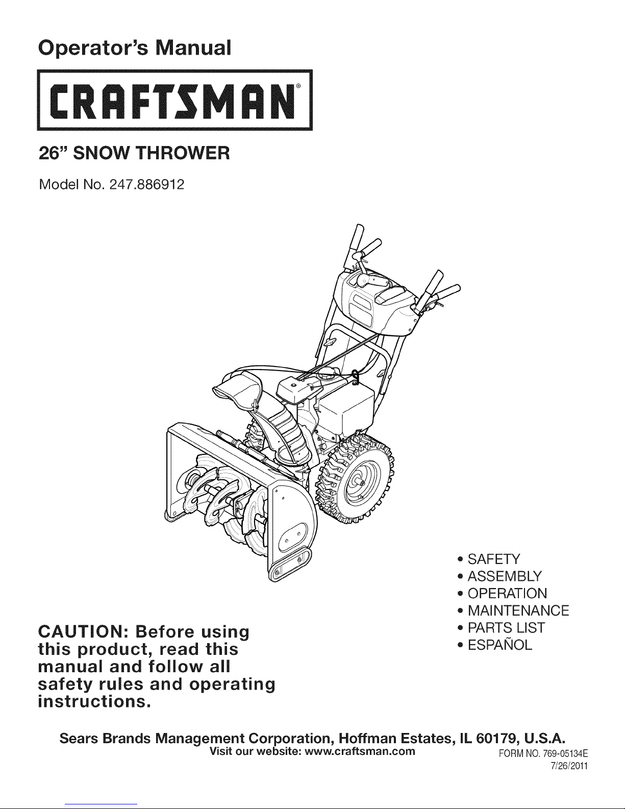
Operator's Manual
CRRFr MRN
26" SNOW THROWER
Model No. 247.886912
CAUTION: Before using
this product, read this
manual and follow all
safety rules and operating
instructions.
Sears Brands Management Corporation, Hoffman Estates, IL 60179, U.S.A.
Visit our website: www.craftsman.com FORMNO.769-05134E
o SAFETY
ASSEMBLY
OPERATION
MAINTENANCE
PARTS LIST
o ESPANOL
7/26/2011
Page 2
WarrantyStatement.................... Page2
SafeOperationPractices.............. Pages3-6
Assembly......................... Pages8-13
Operation........................ Pages14-17
Service&Maintenance.............. Pages18-23
Troubleshooting...................... Page25
PartsList......................... Pages26-43
RepairProtectionAgreement............ Page47
Espadol............................. Page48
ServiceNumbers................... BackPage
Off-SeasonStorage................... Page24
CRAFTSMANTWOYEARFULLWARRANTY
FORTWOYEARSfromthedateofpurchase,thisproductiswarrantedagainstanydefectsinmaterialorworkmanship.Defectiveproductwill
receivefreerepairorfreereplacementifrepairisunavailable.
Thiswarrantyisvoidifthisproductiseverusedwhileprovidingcommercialservicesorifrentedtoanotherperson.
Forwarrantycoveragedetails to obtain repairor replacement,visit the website: www.craftsman.com
This warranty covers ONLYdefects in material andworkmanship. Warrantycoverage does NOTinclude:
• Expendableitemsthatcanwearoutfromnormalusewithinthewarrantyperiod,includingbutnotlimitedtoaugers,augerpaddles,drift
cutters,skidshoes,shaveplate,shearpins,sparkplug,aircleaner,belts,andoil filter.
• Standardmaintenanceservicing,oilchanges,ortune-ups.
• Tirereplacementor repaircausedby puncturesfromoutsideobjects,suchasnails,thorns,stumps,orglass.
Tireor wheelreplacementor repairresultingfromnormalwear,accident,orimproperoperationormaintenance.
Repairsnecessarybecauseof operatorabuse,includingbutnot limitedto damagecausedbyover-speedingtheengine,or fromimpacting
objectsthatbendtheframe,augershaft,etc.
• Repairsnecessarybecauseof operatornegligence,includingbutnotlimitedto,electricalandmechanicaldamagecausedbyimproper
storage,failureto usethepropergradeandamountofengineoil, or failureto maintaintheequipmentaccordingtotheinstructionscontained
intheoperator'smanual.
• Engine(fuelsystem)cleaningorrepairscausedbyfueldeterminedto becontaminatedoroxidized(stale).Ingeneral,fuelshouldbeused
within30 daysof itspurchasedate.
Normaldeteriorationandwearoftheexteriorfinishes,orproductlabelreplacement.
Thiswarrantygivesyouspecificlegalrights,andyoumayalsohaveotherrightswhichvaryfromstatetostate.
Sears Brands Management Corporation, Hoffman Estates, IL 60179
EngineOilType: SAE5W-30
EngineOilCapacity: 20ounces
FuelCapacity: 3 Quarts
SparkPlug: F6RTC
SparkPlugGap: .020"to .030"
©KCDIR LLC
ModelNumber.................................................................
Serial Number.................................................................
Dateof Purchase.............................................................
Recordthemodelnumber,serialnumber
anddateof purchaseabove
2
Page 3
Thissymbolpointsoutimportantsafetyinstructionswhich,if not
followed,couldendangerthepersonalsafetyand/orpropertyof
yourselfandothers. Readandfollowall instructionsin thismanual
beforeattemptingto operatethismachine.Failuretocomplywith
theseinstructionsmayresultin personalinjury.Whenyouseethis
symbol,HEEDITSWARNING!
Thismachinewasbuiltto beoperatedaccordingtothe safeopera-
tionpracticesinthis manual.As withanytypeof powerequipment,
carelessnessorerroron thepartofthe operatorcanresultin serious
injury.Thismachineiscapableofamputatingfingers,hands,toes
andfeetandthrowingdebris.Failuretoobservethe followingsafety
instructionscouldresultin seriousinjuryor death.
CALIFORNIA PROPOSITION 65
EngineExhaust,someof itsconstituents,andcertainvehicle
componentscontainoremitchemicalsknowntoStateofCalifornia
tocausecancerandbirthdefectsorotherreproductiveharm,
TRAiNiNG
• Read,understand,andfollowall instructionson themachineand
in themanual(s)beforeattemptingtoassembleandoperate.
Failuretodo socan resultinseriousinjurytothe operatorand/
orbystanders.Keepthismanualina safeplaceforfutureand
regularreferenceandfor orderingreplacementparts.
• Befamiliarwithall controlsandtheirproperoperation.Knowhow
tostopthe machineanddisengagethemquickly.
• Neverallowchildrenunder14yearsof agetooperatethis
machine.Children14andover shouldreadandunderstandthe
instructionsandsafeoperationpracticesin thismanualandon
themachineandbe trainedandsupervisedbyanadult.
Neverallowadultsto operatethis machinewithoutproper
instruction.
• Thrownobjectscancauseseriouspersonalinjury.Planyour
snow-throwingpatterntoavoiddischargeof materialtoward
roads,bystandersandthe like.
Keepbystanders,petsandchildrenat least75feetfromthe
machinewhileit is in operation.Stopmachineifanyoneenters
thearea.
• Exercisecautiontoavoidslippingorfalling,especiallywhen
operatinginreverse.
Your Responsibility--Restrict theuse of thispowermachineto
personswhoread,understandandfollowthewarningsandinstruc-
tionsin thismanualandon themachine,
SAVE THESE INSTRUCTIONS!
PREPARATION
Thoroughlyinspecttheareawherethe equipmentistobeused.
Removeall doormats,newspapers,sleds,boards,wiresandother
foreignobjects,whichcouldbe trippedoverorthrownbytheauger/
impeller.
• Alwayswearsafetyglassesoreyeshieldsduringoperationand
whileperformingan adjustmentor repairto protectyoureyes.
Thrownobjectswhichricochetcancauseseriousinjurytothe
eyes.
Donot operatewithoutwearingadequatewinteroutergarments.
Donot wearjewelry,longscarvesorotherlooseclothing,which
couldbecomeentangledinmovingparts.Wearfootwearwhich
willimprovefootingonslipperysurfaces.
Usea groundedthree-wireextensioncordand receptacleforall
machineswithelectricstartengines.
Disengageall controlleversbeforestartingtheengine.
Adjustcollectorhousingheighttocleargravelorcrushedrock
surfaces.
• Neverattemptto makeanyadjustmentswhileengineis running,
exceptwherespecificallyrecommendedintheoperator'smanual.
Letengineandmachineadjusttooutdoortemperaturebefore
startingtoclearsnow.
3
Page 4
SafeHandlingof Gasoline
Toavoidpersonalinjuryor propertydamageuseextremecarein
handlinggasoline.Gasolineisextremelyflammableandthevaporsare
explosive.Seriouspersonalinjurycanoccurwhengasolineisspilled
onyourselforyourclotheswhichcanignite.Washyourskinand
changeclothesimmediately.
• Useonlyanapprovedgasolinecontainer.
• Extinguishall cigarettes,cigars,pipesandothersources
ofignition.
• Neverfuelmachineindoors.
• Neverremovegas capor addfuel whilethe engineis hot
or running.
• Allowenginetocoolat leasttwominutesbeforerefueling.
• Neveroverfillfueltank. Filltanktono morethan1/2inch
belowbottomoffillerneckto providespaceforfuel
expansion.
• Replacegasolinecapandtightensecurely.
• Ifgasolineisspilled,wipeit offtheengineandequipment.
Movemachinetoanotherarea.Wait5 minutesbefore
startingtheengine.
• Neverstorethemachineor fuel containerinsidewhere
thereis anopenflame,sparkor pilotlight(e.g.furnace,
waterheater,spaceheater,clothesdryeretc.).
• Allowmachinetocool at least5 minutesbeforestoring.
• Neverfillcontainersinsidea vehicleor ona truckor trailer
bedwitha plasticliner.Alwaysplacecontainersonthe
groundawayfromyourvehiclebeforefilling.
• If possible,removegas-poweredequipmentfromthetruck
ortrailerand refueliton theground.Ifthisisnotpossible,
thenrefuelsuchequipmentona trailerwitha portable
container,ratherthanfromagasolinedispensernozzle.
• Keepthenozzleincontactwiththe rimof the fueltankor
containeropeningatalltimesuntil fuelingis complete.Do
notuse a nozzlelock-opendevice.
OPERATION
• Donotputhandsorfeetnear rotatingparts,inthe auger/impeller
housingorchuteassembly.Contactwiththerotatingpartscan
amputatehandsandfeet.
• Theauger/impellercontrolleveris a safetydevice.Neverbypass
itsoperation.Doingsomakesthe machineunsafeandmaycause
personalinjury.
• Thecontrolleversmustoperateeasilyin bothdirectionsand
automaticallyreturntothedisengagedpositionwhenreleased.
• Neveroperatewitha missingordamagedchuteassembly.Keep
all safetydevicesin placeandworking.
• Neverrunanengineindoorsorina poorlyventilatedarea.Engine
exhaustcontainscarbonmonoxide,anodorlessanddeadlygas.
• Donotoperatemachinewhileundertheinfluenceofalcoholor
drugs.
• Mufflerandenginebecomehotandcancausea burn.Donot
touch.Keepchildrenaway.
• Exerciseextremecautionwhenoperatingonorcrossinggravel
surfaces.Stayalertforhiddenhazardsor traffic.
• Exercisecautionwhenchangingdirectionandwhileoperatingon
slopes.Do notoperateon steepslopes.
• Planyoursnow-throwingpatternto avoiddischargetowards
windows,walls,carsetc. Thus,avoidingpossibleproperty
damageorpersonalinjurycausedbya ricochet.
• Neverdirectdischargeat children,bystandersand petsor allow
anyoneinfrontof the machine.
• Donotoverloadmachinecapacityby attemptingtoclearsnowat
toofastof arate.
• Neveroperatethis machinewithoutgoodvisibilityorlight.Always
be sureof yourfootingand keepafirmholdon thehandles.Walk,
neverrun.
• Disengagepowertotheauger/impellerwhentransportingor not
in use.
• Neveroperatemachineat hightransportspeedsonslippery
surfaces.Lookdownand behindand usecarewhenbackingup.
• Ifthe machineshouldstarttovibrateabnormally,stoptheengine,
disconnectthesparkplugwireandgroundit againstthe engine.
Inspectthoroughlyfor damage.Repairanydamagebefore
startingandoperating.
• Disengageall controlleversandstopenginebeforeyouleave
theoperatingposition(behindthehandles).Waituntiltheauger/
impellercomestoa completestopbeforeuncloggingthechute
assembly,makingany adjustments,or inspections.
• Neverput yourhandinthedischargeorcollectoropenings.Do
notunclogchuteassemblywhileengineisrunning.Shutoff
engineand remainbehindhandlesuntilall movingpartshave
stoppedbeforeunclogging.
• Useonlyattachmentsandaccessoriesapprovedbythemanufac-
turer(e.g.wheelweights,tirechains,cabsetc.).
• Whenstartingengine,pullcordslowlyuntilresistanceisfelt,then
pull rapidly.Rapidretractionofstartercord(kickback)willpull
handandarmtowardenginefasterthanyoucanletgo. Broken
bones,fractures,bruisesorsprainscouldresult.
• Ifsituationsoccurwhichare notcoveredinthis manual,usecare
andgoodjudgment.
• Forin-warrantysafety,operationormaintenancequestions,orto
orderpartsandscheduleservice,call 1-800-4-MY-HOME.
CLEARING A CLOGGED DISCHARGE CHUTE
Handcontactwiththe rotatingimpellerinsidethe dischargechute
is themostcommoncauseof injuryassociatedwithsnowthrowers.
Neveruseyourhandto cleanout thedischargechute.
Toclear thechute:
1. SHUTTHEENGINEOFF!
2. Wait 10secondstobe suretheimpellerbladeshavestopped
rotating.
3. Alwaysusea clean-outtool,notyourhands.
4
Page 5
MAINTENANCE & STORAGE
• Nevertamperwithsafetydevices.Checktheirproperoperation
regularly.Refertothe maintenanceandadjustmentsectionsof
thismanual.
• Beforecleaning,repairing,or inspectingmachinedisengageall
controlleversandstopthe engine.Waituntiltheauger/impeller
cometoa completestop.Disconnectthe sparkplugwireand
groundagainsttheenginetopreventunintendedstarting.
Checkboltsand screwsforpropertightnessatfrequentintervals
tokeepthe machineinsafeworkingcondition.Also,visually
inspectmachineforanydamage.
Donotchangetheenginegovernorsettingorover-speedthe
engine.Thegovernorcontrolsthe maximumsafeoperatingspeed
oftheengine.
Snowthrowershaveplatesandskidshoesaresubjectto wear
anddamage.Foryoursafetyprotection,frequentlycheckall
componentsand replacewithoriginalequipmentmanufacturer's
(OEM)partsonlyas listedinthe Partspagesof thisoperator's
manual.Useofpartswhichdonotmeetthe originalequipment
specificationsmayleadto improperperformanceandcompro-
misesafety!
Checkcontrolleversperiodicallytoverifytheyengageanddisen-
gageproperlyandadjust,if necessary.Referto the adjustment
sectioninthisoperator'smanualforinstructions.
Maintainor replacesafetyandinstructionlabels,as necessary.
Observeproperdisposallawsand regulationsfor gas,oil,etc.to
protecttheenvironment.
Priorto storing,runmachinea few minutestoclearsnowfrom
machineand preventfreezeupofauger/impeller.
Neverstorethemachineorfuel containerinsidewherethereisan
openflame,sparkorpilot lightsuchasa waterheater,furnace,
clothesdryeretc.
Alwaysrefertotheoperator'smanualforproperinstructionson
off-seasonstorage.
Checkfuelline,tank,cap,andfittingsfrequentlyforcracksor
leaks.Replaceif necessary.
Donotcrankenginewithsparkplugremoved.
Accordingtothe ConsumerProductsSafetyCommission(CPSC)
andtheU.S.EnvironmentalProtectionAgency(EPA),thisproduct
hasan AverageUsefulLifeof seven(7)years,or 60 hoursof
operation.Atthe endoftheAverageUsefulLifehavethemachine
inspectedannuallybyan authorizedservicedealertoensurethat
allmechanicalandsafetysystemsareworkingproperlyandnot
wornexcessively.Failuretodo socanresultinaccidents,injuries
ordeath.
DO NOT MODIFY ENGINE
Toavoidseriousinjuryor death,do not modifyengineinanyway.
Tamperingwiththegovernorsettingcanleadto a runawayengineand
causeitto operateat unsafespeeds.Nevertamperwithfactorysetting
ofenginegovernor.
NOTICE REGARDING EMiSSiONS
EngineswhicharecertifiedtocomplywithCaliforniaandfederal
EPAemissionregulationsforSORE(SmallOffRoadEquipment)are
certifiedto operateon regularunleadedgasoline,and mayinclude
thefollowingemissioncontrolsystems:EngineModification(EM),
OxidizingCatalyst(OC),SecondaryAirInjection(SAI)and ThreeWay
Catalyst(TWO)if soequipped.
SPARK ARRESTOR
Thismachineisequippedwithaninternalcombustionengineand
shouldnotbe usedonor nearanyunimprovedforest-covered,
brush-coveredorgrass-coveredlandunlessthe engine'sexhaust
systemisequippedwitha sparkarrestormeetingapplicablelocalor
statelaws(ifany)
Ifa sparkarrestorisused,it shouldbe maintainedin effectiveworking
orderbytheoperator.IntheStateof Californiatheaboveis required
bylaw (Section4442oftheCaliforniaPublicResourcesCode).Other
statesmayhavesimilarlaws. Federallawsapplyonfederallands.
A sparkarrestorfor themuffleris availablethroughyournearestSears
PartsandRepairServiceCenter.
Page 6
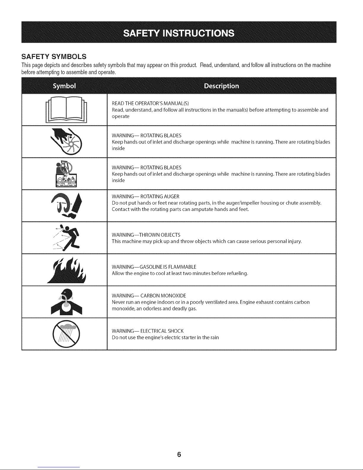
SAFETY SYMBOLS
Thispagedepictsanddescribessafetysymbolsthatmayappearonthisproduct. Read,understand,andfollowall instructionson themachine
beforeattemptingto assembleandoperate.
READ THE OPERATOR'S MANUAL(S)
i
. +
i
Read, understand, and follow all instructions in the manual(s) before attempting to assemble and
operate
WARNING-- ROTATING BLADES
Keep hands out of inlet and discharge openings while machine is running. There are rotating blades
inside
WARNING-- ROTATING BLADES
Keep hands out of inlet and discharge openings while machine is running. There are rotating blades
inside
WARNING-- ROTATING AUGER
Do not put hands or feet near rotating parts, in the auger/impeller housing or chute assembly.
Contact with the rotating parts can amputate hands and feet.
"JIp
WARNING--THROWN OBJECTS
This machine may pick up and throw objects which can cause serious personal injury.
WARNING--GASOLINE IS FLAMMABLE
Allow the engine to cool at least two minutes before refueling.
WARNING-- CARBON MONOXIDE
Never run an engine indoors or in a poorly ventilated area. Engine exhaust contains carbon
monoxide, an odorless and deadly gas+
WARNING-- ELECTRICAL SHOCK
Do not use the engine's electric starter in the rain
6
Page 7

Thispageleftintentionallyblank.
7
Page 8
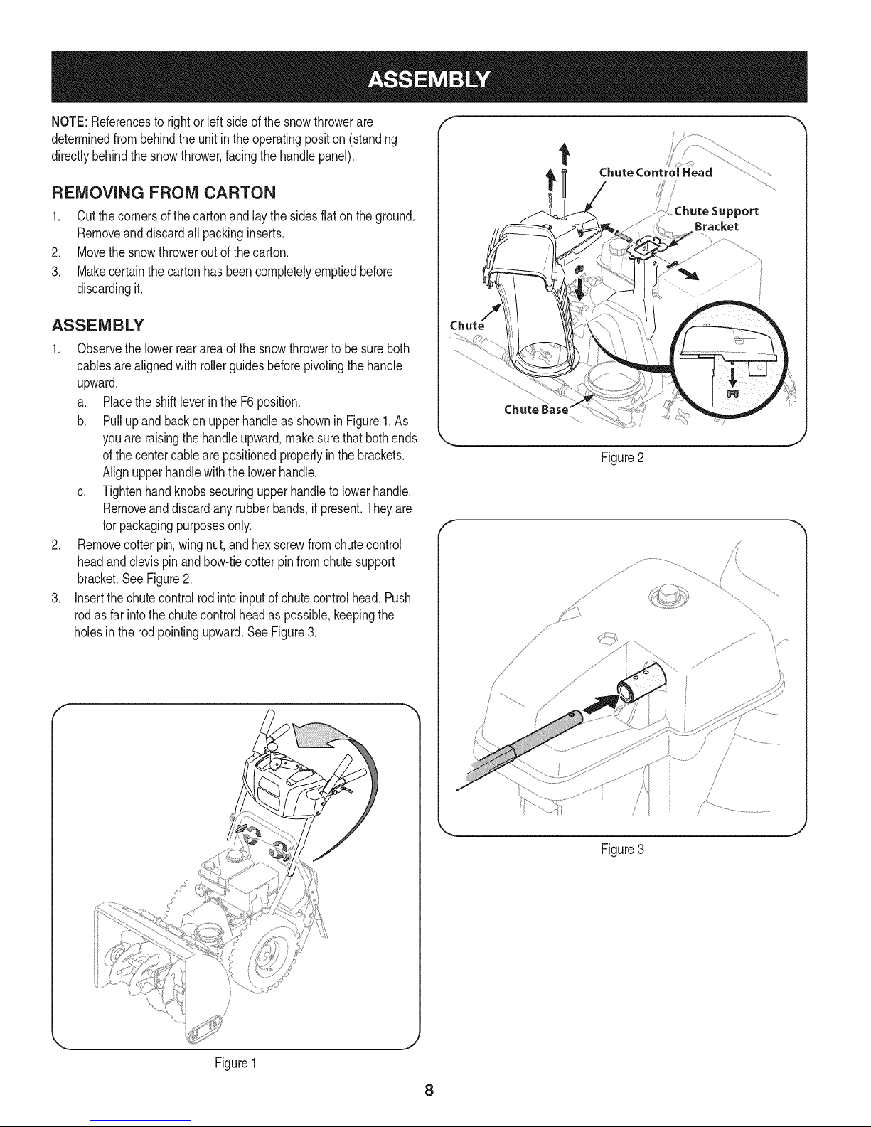
NOTE:Referencesto rightorleft sideofthesnowthrowerare
determinedfrombehindtheunit intheoperatingposition(standing
directlybehindthesnowthrower,facingthe handlepanel).
REMOVING FROM CARTON
1. Cutthe cornersof thecartonandlay the sidesflaton theground.
Removeanddiscardallpackinginserts.
2. Movethesnowthroweroutofthecarton.
3. Makecertainthecartonhas beencompletelyemptiedbefore
discardingit.
ASSEMBLY
1. Observethe lowerrearareaof the snowthrowertobesureboth
cablesarealignedwith rollerguidesbeforepivotingthehandle
upward.
a. Placethe shiftleverin theF6position.
b. Pullupandbackon upperhandleasshownin Figure1.As
youare raisingthehandleupward,makesurethat bothends
ofthecentercablearepositionedproperlyinthebrackets.
Alignupperhandlewiththe lowerhandle.
c. Tightenhandknobssecuringupperhandleto lowerhandle.
Removeanddiscardany rubberbands,if present.Theyare
forpackagingpurposesonly.
2. Removecotterpin,wing nut,andhexscrewfromchutecontrol
headandclevispinandbow-tiecotterpinfromchutesupport
bracket.SeeFigure2.
3. Insertthe chutecontrolrodintoinputofchutecontrolhead.Push
rodasfar intothechutecontrolheadaspossible,keepingthe
holesin therodpointingupward.SeeFigure3.
Chute Control Head
_ort
Bracket
Figure2
f
/
\
Figure1
_J
Figure3
8
Page 9
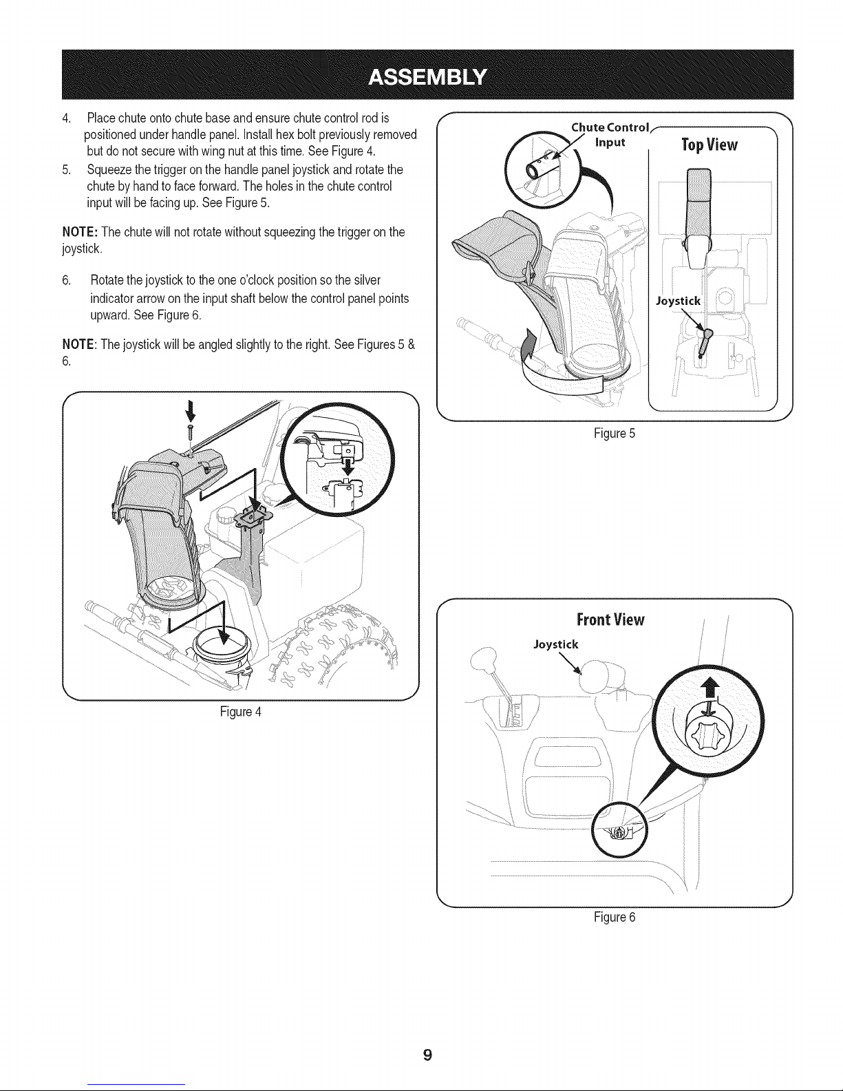
4. Placechuteontochutebaseandensurechutecontrolrodis
positionedunderhandlepanel.Installhexboltpreviouslyremoved
butdo notsecurewithwingnutatthistime.See Figure4.
5. Squeezethetriggeron the handlepaneljoystickand rotatethe
chutebyhandto faceforward.Theholesinthe chutecontrol
inputwill befacingup. SeeFigure5.
NOTE:The chutewill notrotatewithoutsqueezingthe triggeronthe
joystick.
6. Rotatethejoystickto theoneo'clockpositionsothesilver
indicatorarrowonthe inputshaftbelowthecontrolpanelpoints
upward.SeeFigure6.
NOTE:Thejoystickwillbe angledslightlyto theright.SeeFigures5 &
6.
f
Chute Controlf
Figure5
Figure4
f
FroatView
Joystick
J
Figure6
9
Page 10
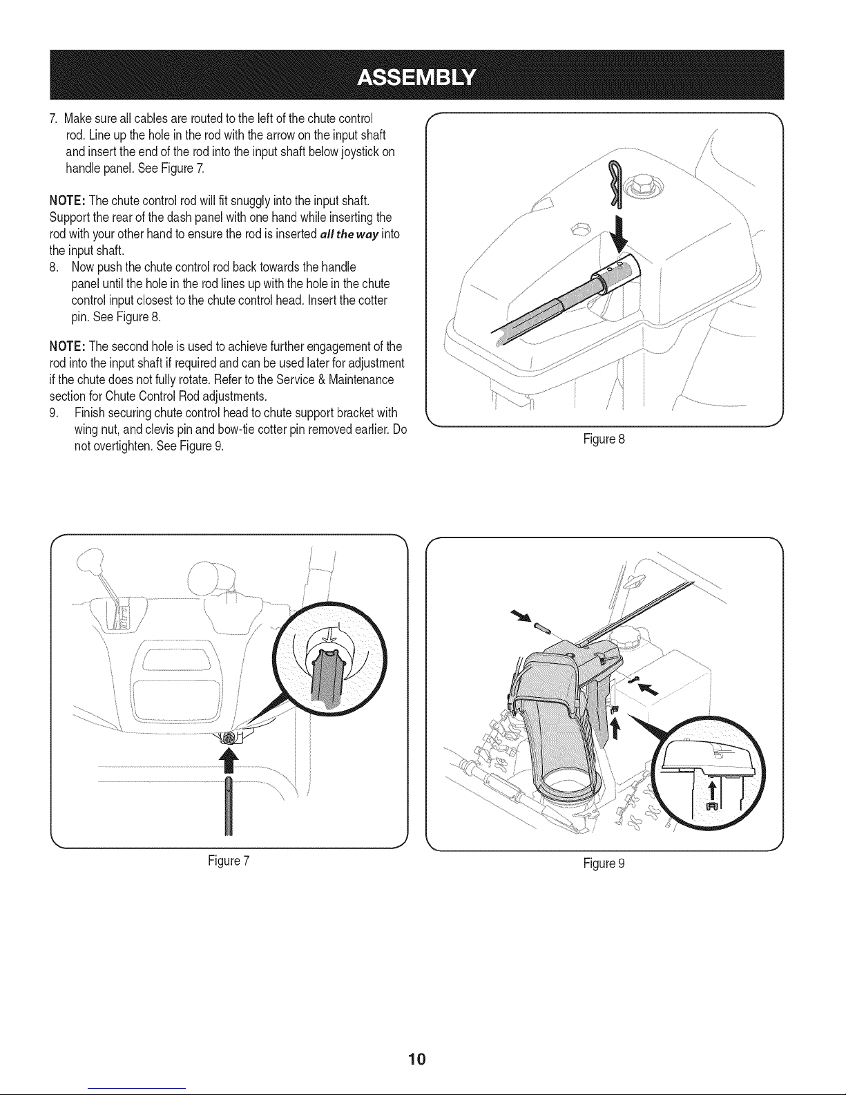
7. Makesureall cablesare routedtotheleftof thechutecontrol
rod.Lineupthe holein therodwiththearrowon theinputshaft
and insertthe endofthe rodintotheinputshaftbelowjoystickon
handlepanel.SeeFigure7.
NOTE:Thechutecontrolrodwillfit snugglyintotheinputshaft.
Supporttherearof thedash panelwithone handwhileinsertingthe
rodwithyourotherhandto ensuretherodis insertedall the way into
theinputshaft.
8. Nowpushthe chutecontrolrodbacktowardsthehandle
paneluntilthe holein therodlinesupwiththe holeinthechute
controlinputclosesttothechutecontrolhead.Insertthecotter
pin.SeeFigure8.
NOTE:The secondholeis usedtoachievefurtherengagementofthe
rodintotheinputshaftifrequiredandcanbe usedlaterfor adjustment
ifthechutedoesnotfullyrotate.Refertothe Service& Maintenance
sectionforChuteControlRodadjustments.
9. Finishsecuringchutecontrolheadto chutesupportbracketwith
wingnut,andclevispinandbow-tiecotterpinremovedearlier.Do
notovertighten.SeeFigure9.
Figure8
/
/
/
.J
' .....................................................i;"i
Figure7
/
i
}
Figure9
10
Page 11
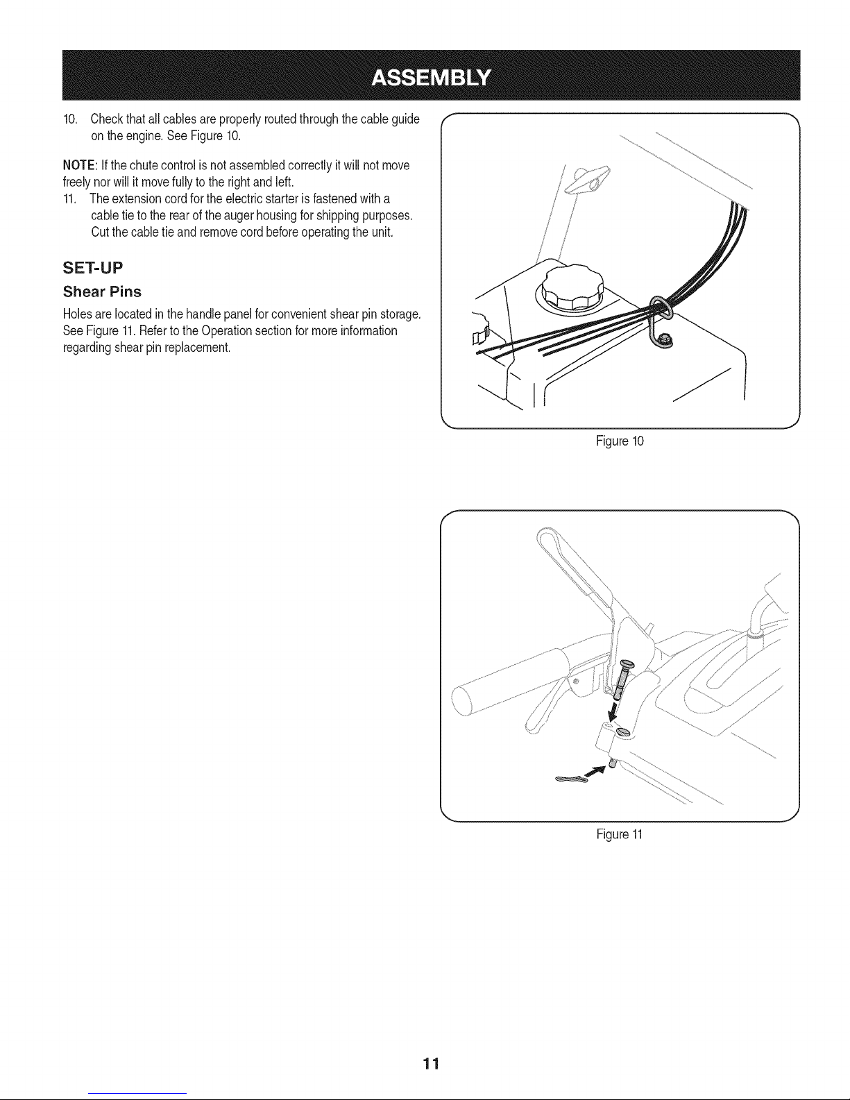
10. Checkthatallcablesareproperlyroutedthroughthecable guide "_
on theengine.SeeFigure10.
NOTE:Ifthechutecontrolis notassembledcorrectlyit willnotmove
freelynorwillit movefullyto therightandleft.
11. Theextensioncordforthe electricstarterisfastenedwitha
cabletie to therearof theaugerhousingforshippingpurposes.
Cutthecabletie and removecordbeforeoperatingthe unit.
SET-UP
Shear Pins
Holesare locatedinthehandlepanelforconvenientshearpin storage.
SeeFigure11.Refertothe Operationsectionformoreinformation
regardingshearpin replacement.
f
/
i
/
/
I
Figure10
J
Figure11
11
Page 12
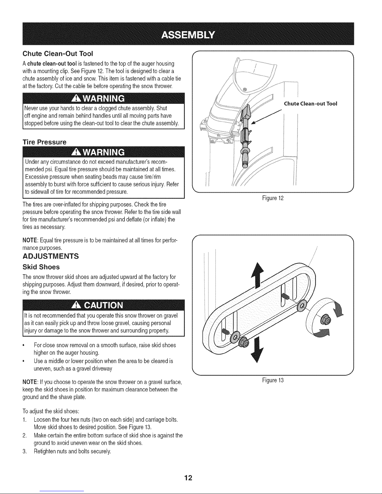
Chute Clean=Out Tool
Achute clean-out tool isfastenedtothe top oftheaugerhousing
witha mountingclip.SeeFigure12.Thetool isdesignedtocleara
chuteassemblyoficeandsnow.Thisitemisfastenedwitha cabletie
atthefactory.Cutthecable tiebeforeoperatingthesnowthrower.
loft _1 .allmovingpartshave
stoppedbeforeusingtheclean-outtoolto clearthe chuteassembly.
Tire Pressure
Underanycircumstancedo notexceedmanufacturer'srecom-
mendedpsi.Equaltire pressureshouldbe maintainedat all times.
Excessivepressurewhenseatingbeadsmaycausetire/rim
assemblytoburstwithforcesufficienttocauseseriousinjury.Refer
tosidewallof tirefor recommendedpressure.
Thetiresareover-inflatedforshippingpurposes.Checkthetire
pressurebeforeoperatingthe snowthrower.Refertothetiresidewall
fortiremanufacturer'srecommendedpsianddeflate(or inflate)the
tiresasnecessary.
Chutedean=out Tool
Figure12
NOTE:Equaltire pressureisto be maintainedat alltimesfor perfor-
mancepurposes.
ADJUSTMENTS
Skid Shoes
Thesnowthrowerskidshoesareadjustedupwardatthefactoryfor
shippingpurposes.Adjustthemdownward,ifdesired,priorto operat-
ingthesnowthrower.
It is notrecommendedthatyouoperatethissnowthrowerongravel
asitcaneasilypickup andthrowloosegravel,causingpersonal
njuryordamageto thesnowthrowerand surroundng property.
• Forclosesnowremovalona smoothsurface,raiseskidshoes
higherontheaugerhousing.
• Usea middleorlowerpositionwhentheareatobe clearedis
uneven,suchas a graveldriveway
NOTE:If youchoosetooperatethesnowthrowerona gravelsurface,
keepthe skidshoesin positionformaximumclearancebetweenthe
groundandtheshaveplate.
Toadjustthe skidshoes:
1. Loosenthefour hexnuts(twooneachside)andcarriagebolts.
Moveskidshoestodesiredposition.SeeFigure13.
2. Makecertaintheentirebottomsurfaceof skidshoeis againstthe
groundtoavoidunevenwearontheskidshoes.
3. Retightennutsand boltssecurely.
Figure13
12
Page 13
Priortooperatingyoursnowthrower,carefullyreadandfollowall
instructionsbelow.Performalladjustmentsto verifyyoursnow
throwerisoperatingsafelyandproperly.
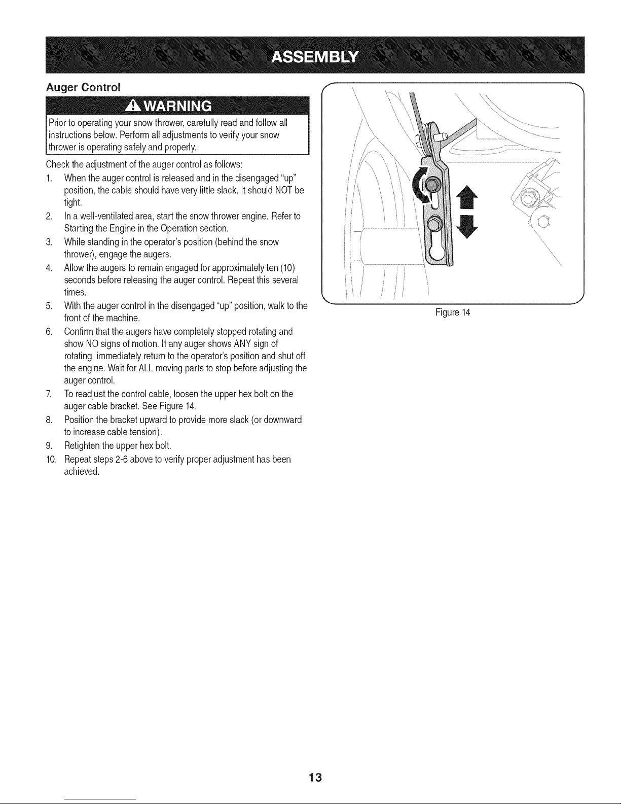
Checktheadjustmentof theaugercontrolasfollows:
1. Whentheaugercontrolis releasedandin the disengaged"up"
position,thecableshouldhavevery littleslack.ItshouldNOTbe
tight.
2. Ina well-ventilatedarea,startthesnowthrowerengine.Referto
StartingtheEngineinthe Operationsection.
3. Whilestandingintheoperator'sposition(behindthe snow
thrower),engagethe augers.
4. Allowtheaugersto remainengagedforapproximatelyten(10)
secondsbeforereleasingthe augercontrol.Repeatthisseveral
times.
5. Withtheaugercontrolin thedisengaged"up"position,walktothe
frontofthe machine.
6. Confirmthatthe augershavecompletelystoppedrotatingand
showNOsignsof motion.If anyaugershowsANYsignof
rotating,immediatelyreturntotheoperator'spositionandshutoff
theengine.WaitforALLmovingpartstostopbeforeadjustingthe
augercontrol.
7. Toreadjustthecontrolcable,loosentheupperhexbolt onthe
augercablebracket.SeeFigure14.
8. Positionthe bracketupwardtoprovidemoreslack(or downward
toincreasecabletension).
9. Retightentheupperhexbolt.
10. Repeatsteps2-6aboveto verifyproperadjustmenthasbeen
achieved.
Figure14
13
Page 14
f
Shift Lever
J
Drive Control
Gas Cap
J
z Four=WayChuteControP (Joystick)
J
j_ Auger Control
...........WheelSteeringControl
ChuteAssembly
\\\\
Muffler Recoil Starter
Clean Out
Tool
Primer
,\\ .d e
\
Key
Fill
Throttle
Control
Choke
Control
/
Augers
Skid Shoe
Oil Drain Electric Starter Outlet
Figure15
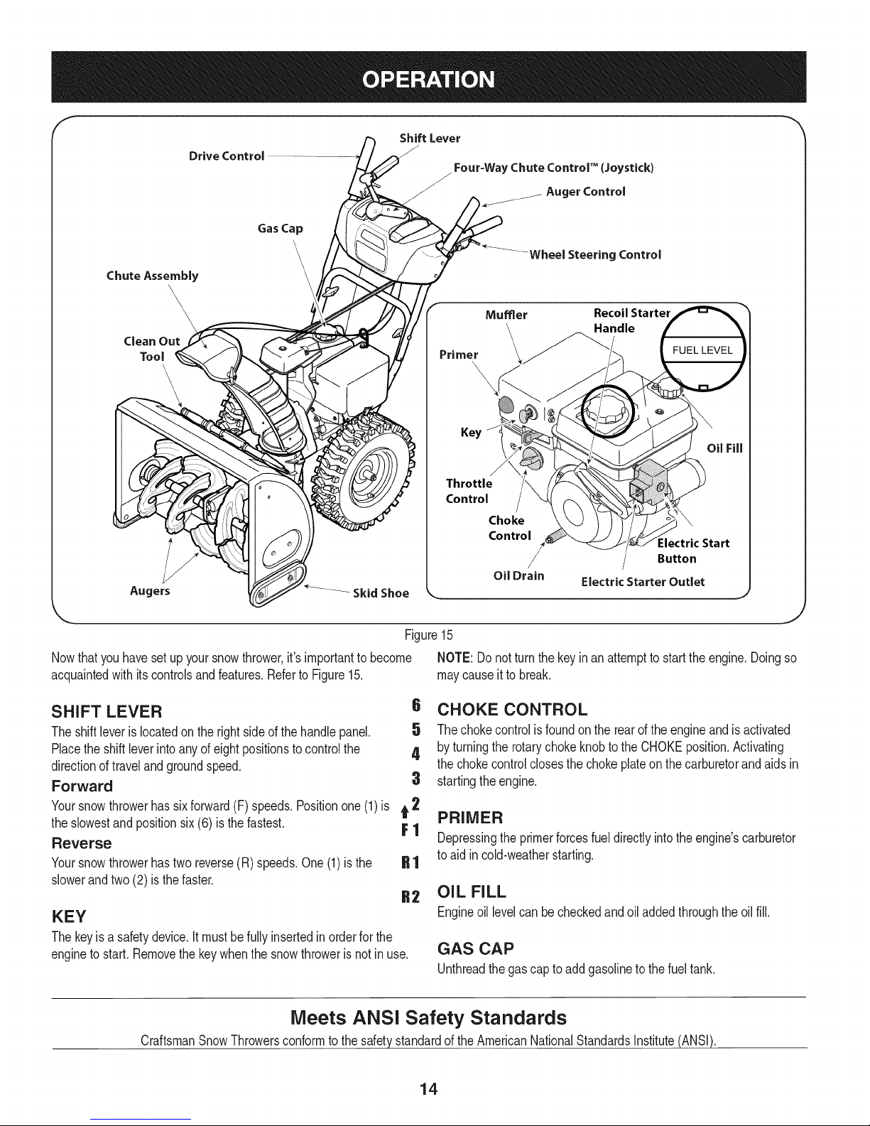
Nowthat youhavesetup yoursnowthrower,it'simportanttobecome NOTE:Donot turnthe keyinan attemptto starttheengine.Doingso
acquaintedwith itscontrolsandfeatures.RefertoFigure15. maycauseit to break.
SHIFT LEVER
Theshiftleveris locatedonthe rightsideofthehandlepanel.
Placethe shiftleverintoanyofeightpositionstocontrolthe
directionoftravelandgroundspeed.
Forward
Yoursnowthrowerhassixforward(F) speeds.Positionone(1)is t 2
6 CHOKE CONTROL
5 The chokecontrolisfoundon the rearof theengineand isactivated
4 by turningthe rotarychokeknobtotheCHOKEposition.Activating
thechokecontrolclosesthe chokeplateonthecarburetorandaidsin
3 startingtheengine.
PRIMER
theslowestand positionsix (6) isthe fastest. F 1
Reverse
Yoursnowthrowerhastwo reverse(R)speeds.One(1)is the
Depressingthe primerforcesfueldirectlyintotheengine'scarburetor
toaid incold-weatherstarting.
slowerandtwo(2) is the faster.
OIL FILL
KEY
Thekeyisa safetydevice.Itmustbefully insertedin orderfor the
enginetostart.Removethekeywhenthe snowthroweris notin use.
Engineoil levelcan becheckedandoiladdedthroughtheoil fill.
GAS CAP
Unthreadthegascaptoadd gasolinetothefueltank.
:lectric Start
Button
J
Meets ANSi Safety Standards
CraftsmanSnowThrowersconformto thesafetystandardof the AmericanNationalStandardsInstitute(ANSI).
14
Page 15
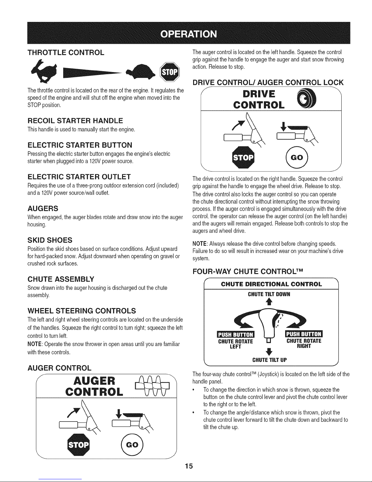
THROTTLE CONTROL
Thethrottlecontrolis locatedon therearof the engine.It regulatesthe
speedof theengineandwillshutoff theenginewhenmovedintothe
STOPposition.
RECOIL STARTER HANDLE
Thishandleisusedto manuallystarttheengine.
ELECTRIC STARTER BUTTON
Pressingtheelectricstarterbuttonengagestheengine'selectric
starterwhenpluggedintoa 120Vpowersource.
Theaugercontrolis locatedonthelefthandle.Squeezethecontrol
gripagainstthehandleto engagethe augerand startsnowthrowing
action.Releaseto stop.
DRIVE CONTROL/AUGER CONTROL LOCK
DRIVE
CONTROL
ELECTRIC STARTER OUTLET
Requirestheuseof athree-prongoutdoorextensioncord(included)
anda 120Vpowersource/walloutlet.
AUGERS
Whenengaged,theaugerbladesrotateanddrawsnowintothe auger
housing.
SKID SHOES
Positiontheskid shoesbasedonsurfaceconditions.Adjustupward
forhard-packedsnow.Adjustdownwardwhenoperatingongravelor
crushedrocksurfaces.
CHUTE ASSEMBLY
Snowdrawnintotheaugerhousingisdischargedoutthechute
assembly.
WHEEL STEERING CONTROLS
Theleft andrightwheelsteeringcontrolsarelocatedon theunderside
ofthehandles.Squeezetherightcontrolto turnright;squeezetheleft
controltoturnleft.
NOTE:Operatethesnowthrowerinopenareasuntilyouarefamiliar
withthesecontrols.
AUGER CONTROL
Thedrivecontrolis locatedon therighthandle.Squeezethecontrol
gripagainstthehandleto engagethe wheeldrive.Releasetostop.
Thedrivecontrolalso lockstheaugercontrolso youcan operate
thechutedirectionalcontrolwithoutinterruptingthesnowthrowing
process.If theaugercontrolisengagedsimultaneouslywiththedrive
control,the operatorcanreleasetheaugercontrol(onthelefthandle)
andtheaugerswillremainengaged.Releasebothcontrolstostopthe
augersandwheeldrive.
NOTE:Alwaysreleasethedrivecontrolbeforechangingspeeds.
Failureto dosowillresultinincreasedwearon yourmachine'sdrive
system.
FOUR-WAY CHUTE CONTROL TM
CHUTE DiRECTiONAl CONTROL
CHUTETiLTgOWN
t
CHUTEROTATE CHUTEROTATE
LEFT RIGHT
#
CHUTETiLTUP J
Thefour-waychutecontroFM(Joystick)islocatedon theleft sideof the
handlepanel.
* Tochangethedirectioninwhichsnowisthrown,squeezethe
buttononthechutecontrolleverandpivotthechutecontrollever
tothe rightorto theleft.
* Tochangetheangle/distancewhichsnowisthrown,pivotthe
chutecontrolleverforwardtotiltthe chutedownandbackwardto
tilt the chuteup.
15
Page 16
CLEAN-OUT TOOL
Neveruseyourhandstocleara cloggedchuteassembly.Shut
loft engineandremainbehindhandlesuntil allmovingpartshave
lstoppedbeforeusingtheclean-outtoolto clearthe chuteassembly.
Thechuteclean-outtoolis convenientlyfastenedtotherearofthe
augerhousingwitha mountingclip.Shouldsnowandicebecome
lodgedin thechuteassemblyduringoperation,proceedasfollowsto
safelycleanthechuteassemblyandchuteopening:
1. Releaseboththe AugerControlandtheDriveControl.
2. Stopthe enginebyremovingthe ignitionkey.
3. Removetheclean-outtoolfromtheclipwhichsecuresitto the
rearofthe augerhousing.
4. Usethe shovel-shapedendof theclean-outtooltodislodgeand
scoopanysnowand icewhichhasformedin andnearthechute
assembly.
5. Refastenthe clean-outtooltothe mountingclipontherearof
theaugerhousing,reinserttheignitionkeyandstartthesnow
thrower'sengine.
6. Whilestandingintheoperator'sposition(behindthesnow
thrower),engagethe augercontrolfora fewsecondstoclear any
remainingsnowandice fromthechuteassembly.
BEFORE STARTING ENGINE
Read,understand,andfollowall instructionsandwarningson the
machineand inthismanualbeforeoperating.
Oil
Theunit wasshippedwith oil inthe engine.Checkoillevelbefore
eachoperationtoensureadequateoil intheengine.Forfurther
instructions,refertothe stepson page18.
NOTE:Besureto checkthe engineon a levelsurfacewiththe engine
stopped.
1. Removetheoil fillercap/dipstickandwipethe dipstickclean.
2. insertthecap/dipstickintothe oilfillerneck,butdo NOTscrewit
in.
3. Removetheoil fillercap/dipstick,ifthelevelislow,slowlyadd
oil (5%30, witha minimumclassificationof SF/SG)untiloil level
registersbetweenhigh(H) andlow(L).
NOTE:Do notoverfill.Overfillingwithoil mayresultinenginesmoking,
hardstartingorsparkplugfouling.
4. Replaceandtightencap/dipstickfirmlybeforestartingengine.
Gasoline
Useautomotivegasoline(unleadedor lowleadedtominimizecombus-
tionchamberdeposits)witha minimumof87octane.Gasolinewith
upto 10%ethanolor 15%MTBE(MethylTertiaryButylEther)canbe
used.Neveruseanoil/gasolinemixtureor dirtygasoline.Avoidgetting
dirt,dust,or waterinthefueltank.DONOTuse E85gasoline.
• Refuelina well-ventilatedareawiththeenginestopped.Donot
smokeorallowflamesor sparksinthe areawheretheengineis
refueledor wheregasolineisstored.
• Donotoverfillthefueltank.After refueling,makesurethetank
capisclosedproperlyandsecurely.
• Becarefulnotto spillfuelwhenrefueling.Spilledfuelorfuelvapor
mayignite,ifany fuelis spilled,makesurethe areaisdrybefore
startingthe engine.
• Avoidrepeatedorprolongedcontactwithskinor breathingof
)or.
Useextremecarewhenhandlinggasoline.Gasolineisextremely
flammableandthevaporsare explosive.Neverfuelthe machine
indoorsorwhilethe engineishotor running.Extinguishcigarettes,
cigars,pipesandothersourcesof ignition.
1. Cleanaroundfuel fill beforeremovingcap to fuel.
2. A fuellevelindicatorislocatedin thefueltank.SeeFigure15
inset.Becarefulnottooverfill.Filltank untilfuel reachesthefuel
levelindicatorto allowspaceforfuel expansion.
STARTING THE ENGINE
Alwayskeephandsandfeetclearof movingparts.Donotusea
pressurizedstartingfluid.Vaporsareflammable.
NOTE:Allowtheengineto warmupfor a fewminutesafter starting.
Theenginewillnotdevelopfullpoweruntilit reachesoperating
temperatures.
1. Makecertainboththe augercontrolanddrivecontrolarein the
disengaged(released)position.
2. insertkeyinto slot.Makesureit snapsintoplace.Donotattempt
toturnthekey.
NOTE:Theenginecannotstartwithoutthe keyfullyinsertedintothe
ignitionswitch.
Electric Starter
Theoptionalelectricstarteris equippedwitha groundedthree-wire
powercordandplug,and isdesignedto operateon 120voltAC
householdcurrent.It mustbeusedwitha properlygroundedthree-
prongreceptacleatall timesto avoidthe possibilityofelectricshock.
Followall instructionscarefullypriorto operatingtheelectricstarter.
DONOTuse electricstarterinthe rain.
Determinethatyourhome'swiringis a three-wiregroundedsystem.
Aska licensedelectricianifyou arenotcertain.
Ifyouhavea groundedthree-prongreceptacle,proceedasfollows.
Ifyoudonothavetheproperhousewiring,DONOTusethe electric
starterunderanyconditions.
1. Plugtheextensioncordintotheoutletlocatedontheengine's
surface.Plugtheotherendof extensioncordintoa three-prong
120-volt,grounded,ACoutletina well-ventilatedarea.
16
Page 17
2. Movethrottlecontrolto FAST(rabbit)_J_" position.
3. MovechoketotheCHOKEI,'_1 position(coldenginestart).If
engineiswarm,placechokein RUNposition.
4. Pushprimerthree(3)times,makingsuretocoverventholein
primerbulbwhen pushing.Ifengineiswarm,pushprimeronly
once.Alwayscoverventholewhenpushing.Coolweathermay
requireprimingtobe repeated.
5. Pushstarterbuttonto start engine.Oncetheenginestarts,im-
mediatelyreleasestarterbutton.Electricstarteris equippedwith
thermaloverloadprotection;systemwilltemporarilyshut-downto
allowstartertocool if electricstarterbecomesoverloaded.
6. Astheenginewarms,slowlyrotatethe chokecontroltoRUN
position.Iftheenginefalters,restartengineandrunwithchoke
athalf-chokepositionfor a shortperiodoftime,andthen slowly
rotatethechokeintoRUNposition.
7. Afterengineis running,disconnectpowercordfromelectric
starter.Whendisconnecting,alwaysunplugtheendat the wall
outletbeforeunpluggingtheoppositeendfromthe engine.
Recoil Starter
Donotpullthestarterhandlewhiletheenginerunning.
1. Movethrottlecontrolto FAST(rabbit)_J_ position.
2. MovechoketotheCHOKEI_¢1 position(coldenginestart).If
engineiswarm,placechokein RUNposition.
3. Pushprimerthree(3)times,makingsuretocoverventholewhen
pushing.Ifengineiswarm,pushprimeronlyonce.Alwayscover
ventholewhenpushing.Coolweathermayrequireprimingtobe
repeated.
4. Pullgentlyonthe starterhandleuntilitbeginstoresist,then
pullquicklyandforcefullytoovercomethecompression.Engine
shouldstart.Donot releasethehandleandallow ittosnapback.
ReturnropeSLOWLYtooriginalposition.If required,repeatthis
step.
5. Astheenginewarms,slowlyrotatethe chokecontroltoRUN
position.Iftheenginefalters,restartengineandrunwithchoke
athalf-chokepositionfor a shortperiodoftime,andthen slowly
rotatethechokeintoRUNposition.
TO ENGAGE DRIVE
1. Withthethrottlecontrolinthe Fast(rabbit) position,moveshift
leverintooneof thesixforward(F) positionsor tworeverse(R)
positions.Selecta speedappropriatefor the snowconditionsand
a paceyou'recomfortablewith.
NOTE:Whenselectinga DriveSpeed,use the slowerspeedsuntil
youarecomfortableandfamiliarwiththe operationofthesnow
thrower.
2. Squeezethedrivecontrolagainstthehandleandthesnow
throwerwillmove.Releaseit anddrivemotionwillstop.
NOTE:NEVERrepositionthe shiftlever(changespeedsordirection
oftravel)withoutfirst releasingthe drivecontrolandbringingthesnow
throwertoa completestop.Doingsowill resultinprematurewearto
thesnowthrower'sdrivesystem.
TO ENGAGE AUGERS
1. Toengagethe augersandstartthrowingsnow,squeezethe
augercontrolagainstthelefthandle.Releasetostoptheaugers.
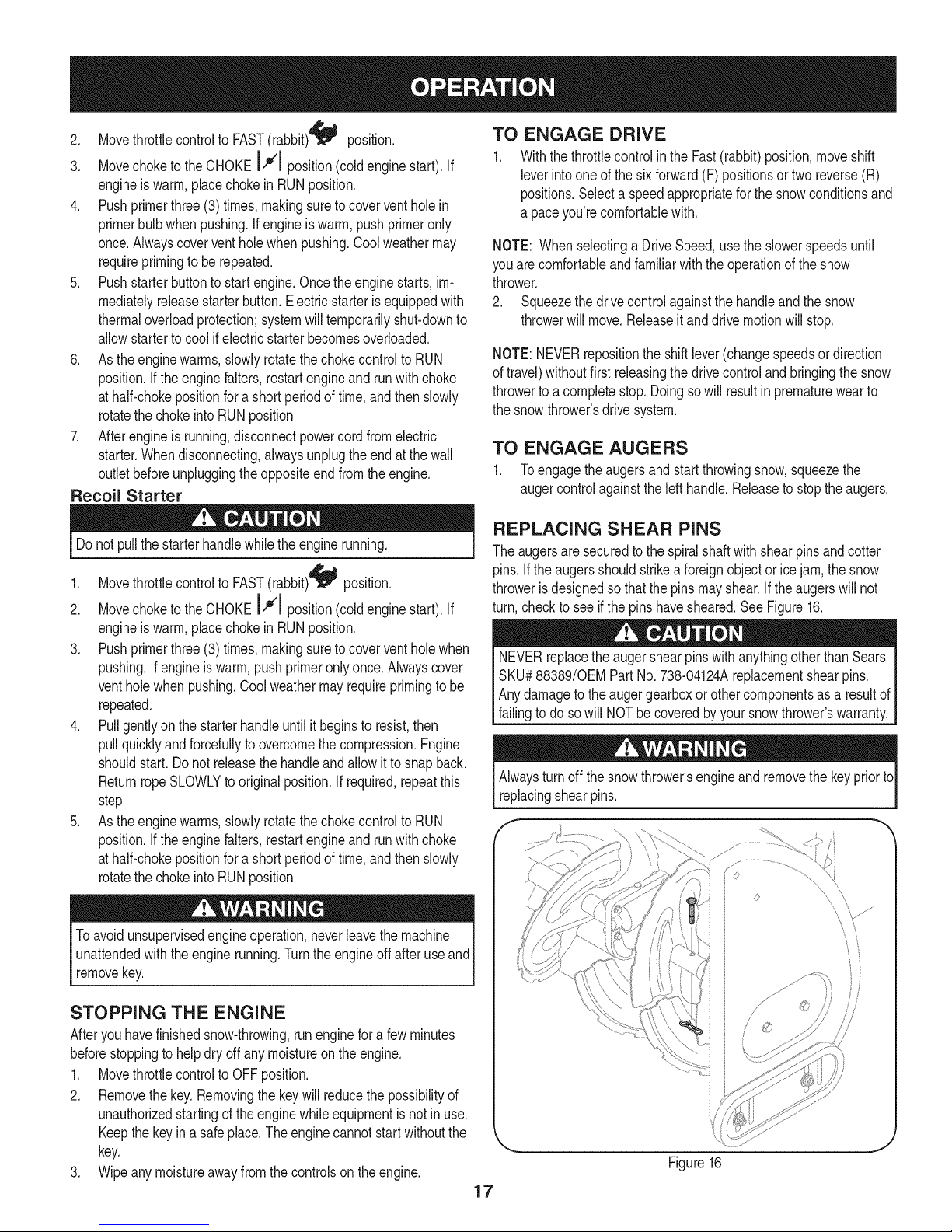
REPLACING SHEAR PiNS
Theaugersaresecuredto thespiralshaftwith shearpinsandcotter
pins.If the augersshouldstrikeaforeignobjectorice jam,thesnow
throwerisdesignedsothatthepinsmayshear.If theaugerswill not
turn,checktoseeifthe pins havesheared.SeeFigure16.
NEVERreplacetheaugershearpinswithanythingotherthanSears
SKU#88389/0EM PartNo.738-04124Areplacementshearpins.
Anydamagetotheaugergearboxorothercomponentsas a resultof
failingto do sowill NOTbecoveredbyyoursnowthrower'swarranty.
Alwaysturnoff thesnowthrower'sengineand removethe keypriorto
replacingshearpins.
f "
Toavoidunsupervisedengineoperation,neverleavethemachine
unattendedwiththeenginerunning.Turntheengineoffafteruse and
removekey.
STOPPING THE ENGINE
Afteryouhavefinishedsnow-throwing,runenginefora few minutes
beforestoppingtohelpdry offanymoistureontheengine.
1. Movethrottlecontrolto OFFposition.
2. Removethekey.Removingthe keywillreducethepossibilityof
unauthorizedstartingoftheenginewhileequipmentisnotin use.
Keepthekeyina safeplace.Theenginecannotstartwithoutthe
key.
3. Wipeanymoistureawayfromthecontrolsontheengine.
",,,\ _V_¸................
\\
_f
/
Figure16
17
Page 18
MAINTENANCE SCHEDULE
Beforeperforminganytypeofmaintenance/service,disengageall
controlsandstoptheengine.Waituntilallmovingpartshavecometo
acompletestop.Disconnectsparkplugwireandgroundit againstthe
enginetopreventunintendedstarting.Alwayswearsafetyglassesduring
operationorwhileperforminganyadjustmentsorrepairs.
EachUseandevery5
hours
1st5 hours
Annuallyor25 hours
Annuallyor50 hours
Annuallyor100hours
BeforeStorage
1. Engineoil level
2. Looseor missinghardware
3. Unitandengine.
1. Engineoil
1. Sparkplug
2. Controllinkagesandpivots
3. Wheels
4. GearshaftandAugershaft
1. Engineoil
1. Sparkplug
1. Fuelsystem
1. Check
2. Tightenor replace
3. Clean
1. Change
1. Check
2. Lubewithlight oil
3. Lubewithmultipurposeautogrease
4. Lubewithlight oil
1. Change
1. Change
1. Runengineuntilit stopsfromlack
ENGINE MAINTENANCE
Checking Engine Oil
Followthemaintenanceschedulegivenbelow.Thischartdescribes
serviceguidelinesonly.Usethe ServiceLogcolumntokeeptrackof
completedmaintenancetasks.To locate the nearestSearsService
Centeror to scheduleservice,simplycontactSearsat
1-800-4-MY-HOME®.
d fuel
Beforelubricating,repairing,or inspecting,disengageall controls
Iandstopengine.Waituntilall movingpartshavecometo acomplete
_stop.
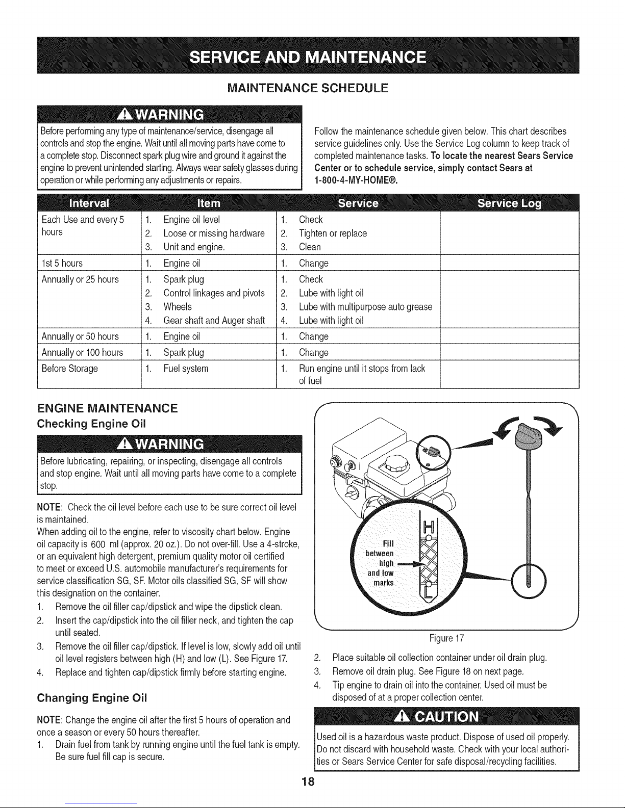
NOTE: Checktheoil levelbeforeeachuseto besurecorrectoil level
ismaintained.
Whenaddingoiltotheengine,referto viscositychart below.Engine
oilcapacityis 600 ml(approx.20 oz.). Donot over-fill.Usea 4-stroke,
oran equivalenthighdetergent,premiumqualitymotoroilcertified
tomeetorexceedU.S.automobilemanufacturer'srequirementsfor
serviceclassificationSG, SR MotoroilsclassifiedSG, SFwill show
thisdesignationonthecontainer.
1. Removetheoil fillercap/dipstickandwipethe dipstickclean.
2. Insertthe cap/dipstickintothe oilfillerneck,andtightenthe cap
untilseated.
3. Removetheoil fillercap/dipstick.Iflevelis low,slowlyaddoiluntil
oil levelregistersbetweenhigh(H) andlow(L).SeeFigure17.
4. Replaceandtightencap/dipstickfirmlybeforestartingengine.
Changing Engine Oil
NOTE:Changetheengineoilafterthefirst5 hoursof operationand
oncea seasonorevery50 hoursthereafter.
1. Drainfuelfromtankby runningengineuntilthefuel tankisempty.
Besurefuelfillcapis secure.
J
Figure17
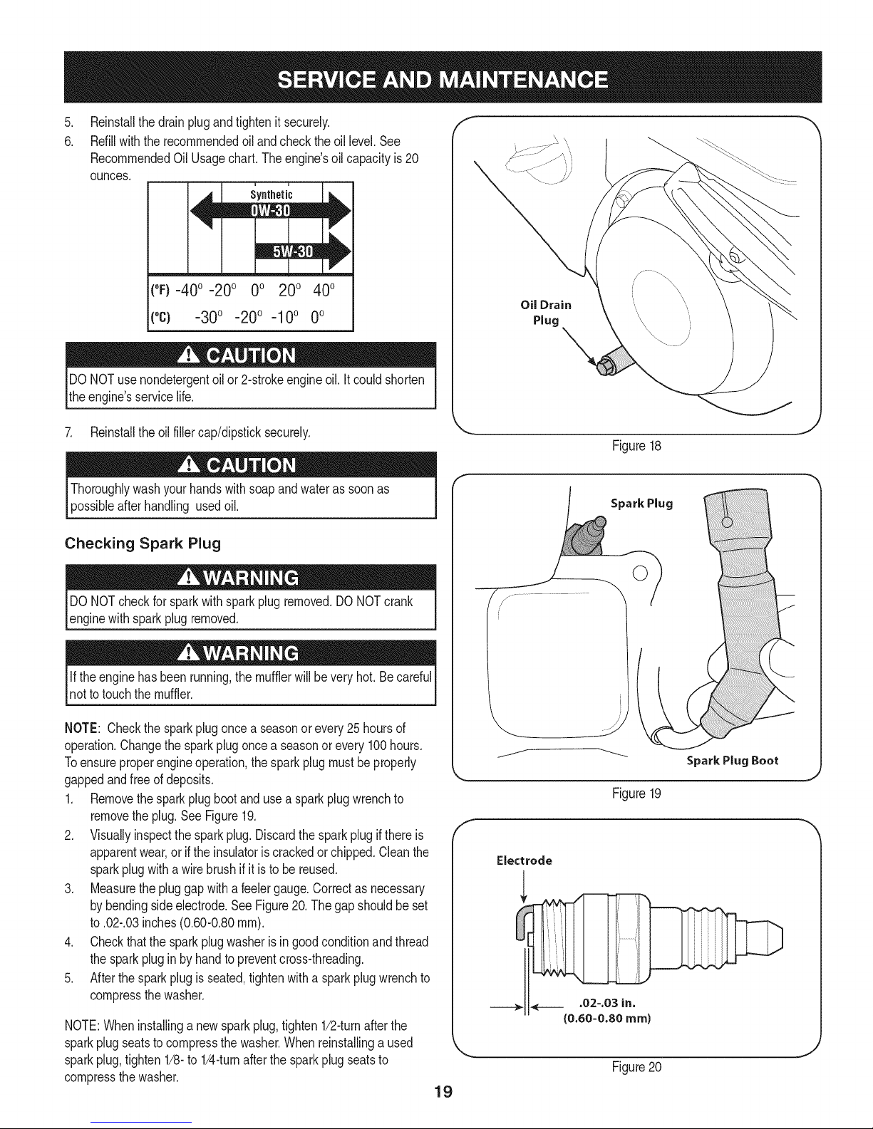
2. Placesuitableoilcollectioncontainerunderoil drainplug.
3. Removeoil drainplug.SeeFigure18on nextpage.
4. Tipenginetodrainoil intothe container.Usedoil mustbe
disposedofata propercollectioncenter.
Usedoil is a hazardouswasteproduct.Disposeof usedoil properly.
IDo notdiscardwithhouseholdwaste.Checkwithyour localauthori-
lties or SearsServiceCenterfor safedisposal/recyclingfacilities.
18
Page 19
.
Reinstallthedrainplugandtightenit securely.
6.
Refillwiththerecommendedoil andchecktheoil level.See
RecommendedOil Usagechart.Theengine'soil capacityis 20
ounces.
i u
[
(%-40 °-20 o 0o 200 400
("c) -300 -200 -10° 0°
DONOTusenondetergentoilor 2-strokeengineoil.Itcouldshorten
theengine'sservicelife.
Oil Drain
Plug
7. Reinstalltheoilfillercap/dipsticksecurely.
Thoroughlywashyourhandswithsoapandwateras soonas
possibleafterhandling usedoil.
Checking Spark Plug
DONOTcheckfor sparkwithsparkplugremoved.DONOTcrank
enginewithsparkplug removed.
Iftheenginehas beenrunning,themufflerwillbevery hot.Becareful
notto touchthemuffler.
NOTE: Checkthesparkplugoncea seasonorevery25hoursof
operation.Changethesparkplugoncea seasonor every100hours.
Toensureproperengineoperation,the sparkplugmustbe properly
gappedandfreeofdeposits.
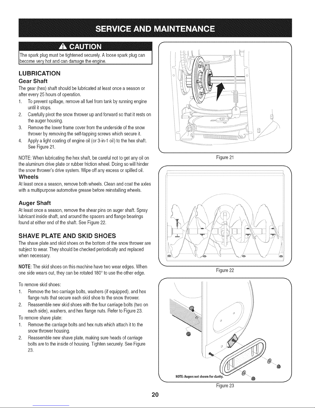
1. Removethesparkplugbootandusea sparkplugwrenchto
removetheplug.See Figure19.
2. Visuallyinspectthesparkplug.Discardthesparkplugifthereis
apparentwear,orif the insulatoriscrackedorchipped.Cleanthe
sparkplugwitha wirebrushif it isto be reused.
3. Measurethe pluggapwitha feelergauge.Correctas necessary
bybendingsideelectrode.SeeFigure20.Thegap shouldbeset
to.02-.03inches(0.60-0.80ram).
4. Checkthatthe sparkplugwasherisingoodconditionandthread
thesparkplugin byhandto preventcross-threading.
5. Afterthesparkplugisseated,tightenwitha sparkplugwrenchto
compressthewasher.
NOTE:Wheninstallinga newsparkplug,tighten1/2-turnafterthe
sparkplugseatstocompressthe washer.Whenreinstallinga used
sparkplug,tighten1/8-to 1/4-turnafterthesparkplugseatsto
compressthewasher.
Figure18
Spark Plug
O
J
Figure19
Electrode
.02-.03 in.
{0.60-0.80 ram)
Figure20
19
Page 20
hotandcan ine.
LUBRICATION
Gear Shaft
Thegear(hex)shaft shouldbelubricatedatleastoncea seasonor
afterevery25 hoursofoperation.
1. Topreventspillage,removeall fuel fromtank by runningengine
untilitstops.
2. Carefullypivotthesnowthrowerupandforwardsothat it restson
theaugerhousing.
3. Removethe lowerframecoverfromtheundersideofthe snow
throwerbyremovingtheself-tappingscrewswhichsecureit.
4. Applya lightcoatingofengineoil (or3-in-1oil) to thehexshaft.
SeeFigure21.
NOTE:Whenlubricatingthehexshaft,be carefulnottogetany oilon
thealuminumdriveplateor rubberfrictionwheel.Doingsowillhinder
thesnowthrower'sdrivesystem.Wipeoffanyexcessor spilledoil.
Wheels
Atleastoncea season,removebothwheels.Cleanandcoattheaxles
witha multipurposeautomotivegreasebeforereinstallingwheels.
Auger Shaft
Atleastoncea season,removethe shearpinson augershaft.Spray
lubricantinsideshaft,andaroundthespacersandflangebearings
foundat eitherendoftheshaft.SeeFigure22.
Figure21
O i
X" "?X
/ .... )
{;:7X
7/'................
)
SHAVE PLATE AND SKID SHOES
Theshaveplateandskidshoesonthebottomofthesnowthrowerare
subjecttowear.Theyshouldbecheckedperiodicallyandreplaced
whennecessary.
NOTE:Theskidshoeson thismachinehavetwowearedges.When
onesidewearsout,theycanbe rotated1800to usetheotheredge.
Toremoveskidshoes:
1. Removethetwocarriagebolts,washers(ifequipped),andhex
flangenutsthat secureeachskidshoetothe snowthrower.
2. Reassemblenewskidshoeswiththefourcarriagebolts(twoon
eachside),washers,andhexflangenuts.Referto Figure23.
Toremoveshaveplate:
1. Removethecarriageboltsand hexnutswhichattachit tothe
snowthrowerhousing.
2. Reassemblenewshaveplate,makingsureheadsof carriage
boltsareto theinsideof housing.Tightensecurely.SeeFigure
23.
/
J
Figure22
f
Figure23
2O
Page 21

ADJUSTMENTS
Shift Cable
If thefull rangeofspeeds(forwardandreverse)cannotbe achieved,
referto the figureto the rightandadjusttheshiftcableasfollows:
1. Placethe shiftleverin thefastest forwardspeedposition(F6).
2. Loosenthehex nuton theshiftcableindexbracket.SeeFigure
24.
3. Pivotthebracketdownwardtotakeupslackinthe cable.
4. Retightenthehexnut.
Drive Control
Whenthedrivecontrolis releasedandin thedisengaged"up"position,
thecableshouldhaveverylittle slack.It shouldNOTbetight.Also,
ifthereis excessiveslackin thedrive cableor ifthe unitexperiences
intermittentdrivewhileusing,thecablemayneedtobeadjusted.
Checktheadjustmentof thedrivecontrolas follows:
1. Withthedrivecontrolreleased,pushthesnowthrowergently
forward.Theunitshouldrollfreely.
2. Engagethe drivecontrolandgentlyattempttopushthesnow
throwerforward.Thewheelsshouldnotturn.The unitshouldnot
rollfreely.
3. Withthedrivecontrolreleased,movetheshiftleverbackand
forthbetweenthe R2positionandthe F6positionseveraltimes.
Thereshouldbeno resistancein theshiftlever.
4. If anyof theabovetestsfailed,the drivecable is in needof adjust-
ment.Proceedasfollows:
5. Shutoff theengineas instructedintheOperationsection.
6. Loosenthelowerhexboltonthe drivecable bracket.SeeFigure
25.
7. Positionthe bracketupwardtoprovidemoreslack(or downward
toincreasecabletension).
8. Retightenthelowerhex boltand repeatsteps1 through4.
J
f
.........
Chute Control Rod
Toachievemorechutecontrolrodengagementinthe inputshaftunder
thehandlepanel,thechutecontrolrodwillhavetobeadjusted.Refer
toFigure26.
Toadjustthis rod,proceedasfollows:
1. Removethecotterpin fromtheholeclosesttothechutecontrol
headon thechutecontrolinput.
2. Pulloutthechutecontrolroduntilthe holein it lines upwiththe
otherholeinthe chutecontrolinput.
3. Reinsertthecotterpinthroughthis holeandthechutecontrolrod.
21
Figure25
/
/ ,
Figure26
J
J
\
\
Page 22
Auger Control f "_
RefertotheAssemblysectionforinstructionsonadjustingtheauger
controlcable.
/
/
/
/
/
/
Skid Shoes
RefertotheAssemblysectionforinstructionsonadjustingthe skid
shoes.
BELT REPLACEMENT
Auger Belt
Toremoveandreplaceyoursnowthrower'saugerbelt,proceedas
follows:
1. Topreventspillage,removeall fuel fromtank by runningengine
untilitstops.
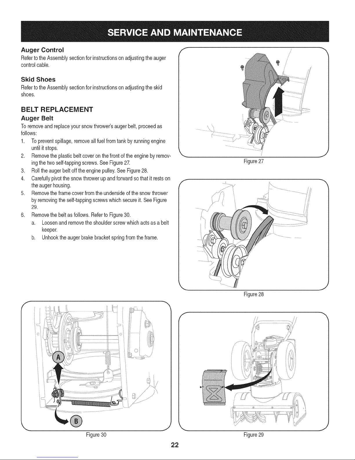
2. Removethe plasticbeltcoveronthefrontoftheenginebyremov-
ingthetwoself-tappingscrews.SeeFigure27.
3. Rolltheaugerbeltoff theenginepulley.See Figure28.
4. Carefullypivotthesnowthrowerupandforwardsothat itrestson
theaugerhousing.
5. Removetheframecoverfromtheundersideofthesnowthrower
byremovingthe self-tappingscrewswhichsecureit.SeeFigure
29.
6. Removethe beltasfollows.RefertoFigure30.
a. Loosenandremovethe shoulderscrewwhichactsasa belt
keeper.
b. Unhookthe augerbrakebracketspringfromthe frame.
Figure27
f
J
Figure30 Figure29
J
Figure28
f
i I
J
Page 23
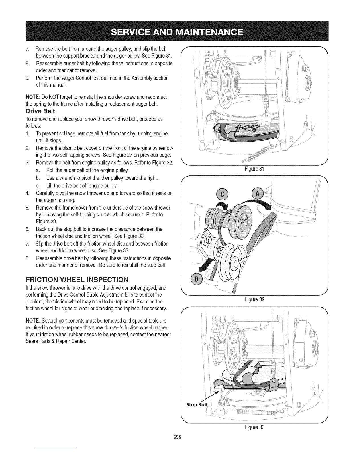
7. Removethebeltfromaroundtheaugerpulley,andslipthebelt
betweenthesupportbracketandtheaugerpulley.SeeFigure31.
8. Reassembleaugerbeltbyfollowingtheseinstructionsinopposite
orderandmannerofremoval.
9. PerformtheAugerControltestoutlinedintheAssemblysection
ofthismanual.
NOTE:DoNOTforgettoreinstalltheshoulderscrewandreconnect
thespringtotheframeafterinstallingareplacementaugerbelt.
Drive Belt
Toremoveandreplaceyoursnowthrower'sdrivebelt,proceedas
follows:
1. Topreventspillage,removeallfuel fromtankby runningengine
untilit stops.
2. Removetheplasticbelt coveronthefrontoftheenginebyremov-
ingthetwoself-tappingscrews.See Figure27on previouspage.
3. Removethebeltfromenginepulleyasfollows.Referto Figure32.
a. Rolltheaugerbeltoff theenginepulley.
b. Useawrenchto pivotthe idlerpulleytowardthe right.
c. Liftthedrivebeltoff enginepulley.
4. Carefullypivotthesnowthrowerupand forwardsothat itrestson
theaugerhousing.
5. Removetheframecoverfromtheundersideofthe snowthrower
byremovingthe self-tappingscrewswhichsecureit.Referto
Figure29.
6. Backoutthestopbolttoincreasethe clearancebetweenthe
frictionwheeldiscandfrictionwheel.SeeFigure33.
7. Slipthedrivebeltoffthefrictionwheeldiscandbetweenfriction
wheelandfrictionwheeldisc.SeeFigure33.
8. Reassembledrivebeltbyfollowingtheseinstructionsinopposite
orderand mannerofremoval.Besureto reinstallthestopbolt.
iO i
Figure31
FRICTION WHEEL INSPECTION
If the snowthrowerfailsto drivewith thedrivecontrolengaged,and
performingtheDriveControlCableAdjustmentfailsto correctthe
problem,thefrictionwheelmayneedtobe replaced.Examinethe
frictionwheelforsignsof wearor crackingandreplaceifnecessary.
NOTE:Severalcomponentsmustbe removedandspecialtoolsare
requiredinorderto replacethissnowthrower'sfrictionwheelrubber.
If yourfrictionwheelrubberneedsto bereplaced,contactthenearest
SearsParts& RepairCenter.
J
Figure32
f
Stop Bol
Figure33
23
Page 24
Ifthe snowthrowerwillnotbe usedfor30 daysor longer,orifit istheendofthesnowseasonwhenthelastpossibilityof snowisgone,the
equipmentneedstobestoredproperly.Followstorageinstructionsbelowtoensuretopperformancefromthesnowthrowerfor manymoreyears.
PREPARING ENGINE
Enginesstoredover30daysneedtobedrainedoffueltoprevent
deteriorationandgumfromforminginfuelsystemoronessential
carburetorparts.If thegasolineinyourenginedeterioratesduring
storage,youmayneedto havethecarburetor,andotherfuelsystem
components,servicedor replaced.
1. Removeall fuel fromtank by runningengineuntilit stops.Donot
attempttopourfuelfromthe engine.
2. Changetheengineoil.
3. Removesparkplugandpourapproximately1oz.(30 rnl)ofclean
engineoil intothe cylinder.Pullthe recoilstarterseveraltimesto
distributetheoil,and reinstallthesparkplug.
4. Cleandebrisfromaroundengine,andunder,around,andbehind
muffler.Applya lightfilmof oilon anyareasthatare susceptible
torust.
• Storeina clean,dry andwellventilatedareaawayfromanyap-
pliancethatoperateswithaflameor pilotlight,suchasa furnace,
waterheater,or clothesdryer.Avoidanyareawitha spark
producingelectricmotor,orwherepowertoolsareoperated.
Neverstoresnowthrowerwithfuelintank indoorsor inpoorlyventi-
latedareas,wherefuelfumesmayreachanopenflame,sparkor pilol
lightas ona furnace,waterheater,clothesdryerorgasappliance.
PREPARING SNOW THROWER
Whenstoringthe snowthrowerin anunventilatedormetalstor-
age shed,careshouldbetakentorustprooftheequipment.Using
a light oilor silicone,coattheequipment,especiallyanychains,
springs,bearingsandcables.
• Removealldirt fromexteriorofengineandequipment.
• Followlubricationrecommendations.
• Storeequipmentina clean,dryarea.
• If possible,avoidstorageareaswithhighhumidity.
• Keeptheenginelevelin storage.Tiltingcancausefueloroil
leakage.
24
Page 25

Enginefailsto start
Enginerunningerratically/
inconsistentRPM(huntingor
surging)
Excessivevibration
Lossofpower
Unitfailstopropelitself
Unitfailstodischargesnow
1. ChokecontrolnotinCHOKEposition.
2. Sparkplugwire disconnected.
3. Faultysparkplug.
4. Fueltankemptyor stalefuel.
5. Enginenotprimed.
6. Keynot inserted.
7. Extensioncordnotconnected(when
usingelectricstartbutton,on modelsso
equipped).
1. EnginerunningonCHOKE.
2. Stalefuel.
3. Waterordirt infuel system.
4. Over-governedengine.
1. Loosepartsor damagedauger.
1. Sparkplugwire loose.
2. Gascap ventholeplugged.
1. Drivecableinneedofadjustment.
2. Drivebeltlooseor damaged.
3. Wornfrictionwheel.
1. Chuteassemblyclogged.
2. Foreignobjectlodgedin auger.
3. Augercablein needof adjustment.
4. Augerbeltlooseordamaged.
5. Shearpin(s)sheared.
1. Movechokecontrolto CHOKEposition.
2. Connectwireto sparkplug.
3. Clean,adjustgap,or replace.
4. Filltankwith clean,freshgasoline.
5. PrimeengineasinstructedintheOperationSection.
6. Insertkeyfully intotheswitch.
7. Connectoneendoftheextensioncordto the electric
starteroutletandtheotherendtoa three-prong
120-volt,grounded,ACoutlet.
1. Movechokecontrolto RUNposition.
2. Filltankwith clean,freshgasoline.
3. Drainfueltankby runningengineuntilitstops.Refill
withfreshfuel.
4. ContactyourSearsParts& RepairCenter.
1. Stopengineimmediatelyand disconnectsparkplug
wire.Tightenall boltsand nuts.Ifvibrationcontinues,
haveunit servicedbya SearsParts& RepairCenter.
1. Connectandtightensparkplugwire.
2. Removeiceand snowfromgascap. Becertainvent
holeisclear.
1. Adjustdrivecontrolcable.RefertoServiceand
Maintenancesection.
2. Replacedrive belt.Referto ServiceandMainte-
nancesection.
3. ChangefrictionwheelorcontactyourSearsParts&
RepairCenter.
1. Stopengineimmediatelyand disconnectsparkplug
wire.Cleanchuteassemblyandinsideof auger
housingwithclean-outtoolor a stick.
2. Stopengineimmediatelyand disconnectsparkplug
wire.Removeobjectfromaugerwith clean-outtool
ora stick.
3. Adjustaugercontrolcable.Referto Assembly
section.
4. Replaceaugerbelt.RefertoServiceand Mainte-
nancesection.
5. Replacewith newshearpin(s).
Chutefailstoeasilyrotate180 1. Disassemblechutecontroland reassembleas
1. Chuteassembledincorrectly.
degrees directedintheAssemblysection.
NEED HORE HELP?
Yot,Fttfind. th_ answer a!ld mo_e on ma_age_y_ifeocom _ for free]
Find this and att your other product manua[s ontine.
Get answers from our team of home experts.
Get a personalized maintenance p[an for your home.
Find information and tools to he[p with home projects.
managemylife
b_e'_g_t_/_eyeu by Sea_s
25
Page 26

Craftsman Snow Thrower Model 247.886912
26
Page 27

Craftsman Snow Thrower IViodel 247.886912
D = 0 0
731-2635 SnowRemovalToolMount
2. 684-04057A-0637 ImpellerAssembly,12"Dia.
3. L710-0347 LHexScrew,3/8-16,1.75,Gr5
4. 710-0451 Bolt,Carriage,5/16-18,.750Grl
5. 710-04484 Screw,5/16-18,0.750
6. 710-0703 Screw,Carriage,1/4-20,.750,Gr5
7. 712-04063 Nut,FlangeLock,5/16-18,Nylon
8. 712-04064 Nut,FlangeLock,1/4-20,Nylon
9. 712-04065 Nut,FlangeLock,3/8-16,Nylon
10. 714-04040 CotterPin,Bow-tie
11. J725-0157 l Cable,Tie,3/16x .05x 7.4
12. 926-04012 Nut,Push-on,.25 Dia
13. 731-07525 Chute,Adapter5" Dia
14. 732-04460 Spring,Extension,.38ODx4.59
15. 736-0174 Washer,Wave,.625x .885x .015
16. 736-0242 Washer,Bell,.340x .872x .060
17. 746-04230A ClutchCable,Auger,47.23"
18. 931-2643 SnowRemovalTool
19. .738-0143 _ Screw,Shoulder,.498x .34,3/8-16
20. 938-0281 Screw,Shoulder,.625x .17,3/8-16
21. 738-04124A ShearPin,.25x 1.50
22. 941-0245 Bearing,HexFlangex .75ID
23. 941-0309 Bearing,Ball,.75 IDx 1.85OD
24. 756-04224 FlatPulley,Idler, 2.75OD
25. 790-00075 Housing,Bearing,1.85ID
26. 790-00080A-0637 Bracket,AugerIdlerw/Brake
27. J918-04172B JGearboxAssembly,Auger,26"
28. 684-04264-0721 HousingAssembly,Auger26"
D = O O
684-04107-0637
30. 684-04108-0637
31. 731-04870
32. 736-0188
33. 741-0493A
34. 790-00087A-0637
35. 790-00121-0721
36. 731-05984A
37. 918-0123A
38. 918-0124A
39. 921-0338
40. 741-0662
41. 710-0642
42. 711-04284
SpiralAssembly,LH
SpiralAssembly,RH
Spacer,1.25ODx .75IDx 1.00
Washer,Flat,.76x 1.49x .06
Bushing,Flange,.80ID x.91OD
Housing,1"HexBearing
ShavePlate,2.25x25.66
SlideShoe
Housing,Auger,RH Reduced
Housing,Auger,LHReduced
Seal,Oil, .750x 1.00x .125
Bearing,Flange,.75x 1.0x.59
Screw,Self-tapping,1/4-20,0.750
Axle,Auger,26"
43. 914-0161 Key,Hi-pro3/16x 5/8
44. 715-04021 Pin,Dowel,.25ODx 1.2
45. 917-04126 Shaft,Worm.75OD
46. 717-04861 Gear,Worm20T
47. 718-04071 Collar,Thrust
48. 721-0325 Plug,1/4x .437
49. 721-0327 Seal,Oil,.75x 1x .131
50. 936-0351 Washer,Flat,.760IDx 1.50D
51. 736-3084 Washer,Flat,.51x 1.12
52. 741-0663 Bearing,Flange,.75x 1.0x.925
53. 741-0661A Bearing,Flange,.75x 1.00x .975
54. 929-0071A ExtensionCord,110V
55. 710-0276 Screw,Carriage,5/16-18x 1.00
56. 936-0159 Washer,Fiat,.349x .879x .063
27
Page 28

Craftsman Snow Thrower Model 247.886912
t< Ij,
28
Page 29

Craftsman Snow Thrower Model 247.886912
684-04112B
2. 738-04367
3. 731-04894D
L L
HandleEngagementAssemblyRH
FlangeShoulderScrew
LockPlate
4. 684-04250 PivotRod
5. 935-0199A RubberBumper
6. 710-3069 Screw,1/4-20x .500
7. 731-04896B ClutchLockCam
8. 712-04081A ShoulderNut, 1/4-20
9. 710-0627 HexScrew,5/16-24x .750
10. 731-06440A LowerChute
11. J720-0274 J HandleGrip
12. 710-1233 Screw,#10-24x0.375
13. 738-04348 ShoulderScrew,1/4-20
14. 710-04586 Screw,1/4-20x 1.625
15. 749-04190A-0637 UpperHandleRH
16. 710-0572 CarriageScrew,5/16-18x2.25
17. 720-04039 ShiftKnob
18. 753-06437 HandlePanel
19. 731-05324 Lens
20. 710-04071 CarriageBolt,5/16-18x 1.0
21. 631-04134B HandleClutchLockRHAssembly
22. 725-0157 CableTie
23. 712-04064 FlangeLockNut,1/4-20
24. 732-0193 CompressionSpring
25. 790-00311A-0637 ShiftLever
26. 790-00248C-0637 PanelBracket
27. 738-04125 ShoulderScrew
28. 684-04311A-0637
29. 946-04396A
30. 736-04446
31. 710-0895
32. 710-04370
33. 731-04427A
34. 918-04801A
35. 710-04187
ChuteSupportBracket
SpeedSelectorCable
FlatWasher,.25x .630x .0515
Hi-LoScrew,1/4-15x .75
HexScrew,1/4-20x3.00
UpperChute
4-WayChuteGearboxAssembly
Hi-LoScrew,1/4-15x 0.5
36. 984-04338 4-WayChuteControlTM Assembly
37. 749-04191A-0637 UpperHandleLH
38. 710-04326 Screw,#8-16x 0.50
39. 732-04219C ClutchLockSpring
D = O O
712-3087 WingNut,1/4-20
41. 714-04040 BowTie CotterPin
42. 710-0262 CarriageBolt,5/16-18x 1.50
43. 631-04133A HandleClutchLockLHAssembly
44. 684-04111B HandleEngagementAssemblyLH
45. 784-5594-0637 CableBracket
46. 720-0284 Wing Knob
47. 712-04063 FlangeLockNut,5/16-18
48. 731-06451 ChuteTilt CableGuide
49. 711-04469A ClevisPin
50. 710-04484 Screw,5/16-18x0.75
51. 749-04138A-0637 LowerHandle
52. 732-04238 TorsionSpring
53. 936-0267 FlatWasher
54. 710-04022 Screw,M8-1.25
55. 936-0264 FlatWasher,.330x .630x .0635
56. 914-0101 Cotter Pin
57. 936-0159 FlatWasher,.349x .879x.063
58. 731-06113 SteeringControl
59. 738-04126 Pin,3/16
60. 716-04036 E-Ring
61. 914-0145 Click Pin
62. 732-0705 CableControlWire
63. 747-05116 ChuteRod
64. 753-06151 HandleAssembly
65. 946-04528A 4-WayCable
946-04477 4-WayCablew/Clip (NotShown)
66. 731-04893A HandlePlunger
67. 710-04879 Screw,Mach.,#8-32x .750
68. 710-04353 Screw,#8 x 1.00
69. 731-07031 HandleLever
70. 984-04324A ShiftAssembly
71. 753-06152 GearSet Assembly
72. 753-06153 HandleHousingAssembly
73. 710-1256 Screw,#8-18x 1.250
74. 684-04350 Joint BlockAssembly
75. 715-04095 Pin
76. 715-0150 RollPin
29
Page 30

Craftsman Snow Thrower IViodel 247.886912 _dJg_, _ i_o_
F__\\'_v/_"_/'_ i"_
42_
i4o;
/
3O
Page 31

D_ i B O ¸
710-1652 ABScrew,1/4-20x0.625
2. 731-05353 BeltCover
3. 735-04099 Plug,3/8 ID
4. 711-1268B ActuatorShaft
5. 746-04229B DriveClutchCable
6. 732-04345 ExtensionSpring
7. 790-00207B DriveClutchCableGuideBracket
8. 684-04156A ShiftRodAssembly
9. 750-04474 AxleSupportTube
10. 914-0126 HiProKey
11. 735-04100 Plug,1/2 ID
12. 917-04210 Gear,56T
13. 941-0245 HexFlangeBearing
14. 790-00206A-0637 AugerClutchCableGuideBracket
15. 756-0625 CableRoller
16. 738-0924A CScrew,1/4-28x0.375
17. 618-04288 DoggAssembly-LH
618-04287 DoggAssembly-RH
18. 926-04012 Push-onNut
19. 750-04477A Spacer
20. 936-3015 Washer,Fiat
21. 732-04311A TorsionSpring,.750IDx.968Lg.
22. 731-05297 Spacer
23. 916-0104 E Ring
24. 736-0188 FiatWasher,.76x 1.49x .06
25. 736-0626 FiatWasher
26. 741-04076 BallBearing
27. 938-04180 Axle
28. L731-04873 Spacer
29. 710-0654A
30. 710-0788
31. 790-00185-0691
32. 634-04147A-0911
634-04148A-0911
33. 736-0242
34. 710-0627
35. 684-04154B-0637
36. 790-00096-0637
3_ 748-0190
38. 738-04184A
39. 790-00316-0637
40. 656-04055
41. 918-04322A
TTSeresScrew,3/8-16x 1.0
TTScrew,1/4-20x 1.0
ShaftRetainer-LH
WheelComplete-LH
WheelComplete-RH
BellWasher
HexBolt,5/16-24x 0.75
FrictionWheelSupportBrkt.Assy.
AugerCableGuideBracket
Spacer
ShoulderScrew
FrameCover
FrictionWheelDiscAssembly
DriveShaftAssembly
m _ O
684-04159 FrictionWheelAssembly
43. 716-0136 RetainerRing
44. 726-0221 SpeedNut
45. 790-00183B-0637 WheelDriveFrame
46. 756-04109 AugerPulley
47. 736-0505 FiatWasher
48. 738-04439 ShoulderScrew
49. 936-0119 LockWasher
50. 684-04169 IdlerPulleyAssembly
51. 790-00289A-0637 Pit.,Cvr.
52. 750-04571 Spacer
53. 732-04308B TorsionSpring
54. 710-0672 HexScrew,5/16-24x 1.25
55. 756-04252 PulleyHalf
56. 954-04260 Belt,WheelDrive
57. 710-0809 TTScrew,1/4-20x 1.25
58. 790-00208C DriveClutchIdlerBracket
59. 748-04112B ShoulderSpacer
60. 932-0264 ExtensionSpring
61. 712-0417A FlangeNut,5/8-18
62. 750-04303 Spacer
63. 756-04113 PulleyHalf
64. 736-0247 FiatWasher
65. 710-0191 HexBolt,3/8-24x 1.25
66. 748-04053A PulleyAdapter
67. 946-0956B SteeringCable
68. 790-00186-0691 ShaftRetainer- RH
69. 750-0767 AxleSpacer
70. 712-04065 FlangeLockNut,3/8-16
71. 954-04050 V-Belt,.500x 35.00 Lg
72. 710-0751 HexScrew,1/4-20x .620
73. 790-00217A-0637 SpeedSelectorPivotBracket
74. 790-00218A-0637 SpeedSelectorShiftBracket
75. 712-04063 FlangeLockNut,5/16-18
76. 712-04064 FlangeLockNut,1/4-20
77. 618-0063A FrictionWheelBearingAssembly
78. 935-04054 FrictionWheel
79. 790-00174 FrictionPlate
80. 710-0599 Screw,1/4-20x .500
81. 936-0329 LockWasher
82. 710-1245B HexBolt,5/16-24x0.875
83. 752Z270-SU ReplacementEngine
31
Page 32

Craftsman Engine IViodel 270=SU=11 For Snow IViodel 247.886912
24
23- ,_
21
25
_2s
m
19
20
20
21
22
23
24
25
26
951-11282
710-04911
951-10657
951-11285
712-04214
951-11111
710-04914
710-04915
951-10642A
m = O O
MufflerAssembly
StudM8x36
MufflerStudAssembly
ExhaustPipeGasket
Nut,M8
ExhaustPipeShield
BoltM6xl0
BoltM6x12
MufflerShield
32
Page 33

Craftsman Engine Model 270=SU=11 For Snow Model 247.886912
43 _44
J
38 39
m
34
35
36
37
38
39
4O
42
43
44
45
951-11897
951-11112
951-10634
712-04213
951-11284
951-10757
951-10637
731-05632
951-10640
951-10635
710-04919
37
D = O Q
CarburetorGasketPlate
ChokeControl
EngineShroud
Nut
ChokeKnob
ThrottleControlKnob
IgnitionSwitchAssembly
Key
Choke PushRod
HeaterBox
BoltM6x25
33
Page 34

Craftsman Engine IViodel 270=SU=11 For Snow IViodel 247.886912
71
77
34
Page 35

Craftsman Engine IViodel 270=SU=11 For Snow IViodel 247.886912
m
52
53
54
55
56
57
58
59
6O
61
62
63
64
65
66
67
68
69
7O
71
72
951-12111
951-11632
951-12007
951-11633
710-04915
951-11113
951-11573
951-11356
736-04461
951-11902
714-04074
951-11575
951-11369
951-10307
951-11247A
951-11576
715-04092
715-04089
951-11371
951-12125
710-04932
D = O O
PistonRingSet
PistonPinSnapRing
Piston
PistonPin
BoltM6x12
Air Shield
ConnectingRodAssembly
GovernorArm Shaft
Washer5.2xl.9
GovernorSeal
CotterPin
CamshaftAssy.
RadialBallBearing,6205
WoodruffKey
CrankshaftKit
(Incl.66-65,76,81)
GovernorGear/ShaftAssembly
DowelPin7x14
DowelPin9x14
CrankcaseCoverGasket
CoverComp,Crankcase
BoltM8x32
m
73
75
76
77
78
79
8O
81
951-11283
951-11577
951-11368
951-11249
951-11350
736-04440
710-04906
951-11370
133
951-10641
952Z270-SU-11
951-11246
951-10661B
951-11059A
951-11060A
Oil FillPlugAssembly
O-Ring15.8x2.5
OilSeal,25x41.25x6
CrankcaseKit
(Incl.61,64,76,77,81)
Oil DrainPipeAssy.
Washer10x16x1.5
Oil DrainPlug
OilSeal25x41.25x6
Oil DrainAssembly
CompleteEngine
CrankcaseCoverKit
(Incl.64,70-73,76)
GasketKit- External
(Incl.4,21,29-31,34,79)
GasketKit- Complete
(Inc1.4,21,29-31,34,46,60,
61,70,76,79,82)
ShortBlock
(Incl.4,21,29,30,46,48,49,
52-55,58-72,74-81)
35
Page 36

Craftsman Engine IViodel 270=SU-11 For Snow IViodel 247.886912
18
13
12 I_ 14
5O
46
134
17
2
36
Page 37

Craftsman Engine IViodel 270=SU=11 For Snow IViodel 247.886912
m
1
2
3
3a
4
5
6
7
8
9
10
11
12
13
14
15
16
17
18
46
47
48
49
5O
51
134
710-04744
951-11054A
731-07059
726-04101
951-11565
951-12000
951-11892
751-11124
751-11123
951-11893
710-04902
951-12002
951-12003
951-12004
951-11894
710-04933
951-11895
951-10668A
951-10292
951-11572
951-10648
951-11899
715-04090
951-10647A
951-10647A
951-11063A
952Z270-SU-11
951-10661B
951-11059A
D = W O
BoltM6x16
ValveCover
BreatherHose
HoseClamp
ValveCoverGasket
Retainer,In.ValveSpring
RockerArmAssembly
Nut,PivotLocking
AdjustingNut,Valve
RockerArm
Bolt,Pivot
Adjuster,ExhValve
Retainer,Ex.ValveSpring
ValveSpring
IntakeValveSeal
BoltM8x55
PushRodGuide
CylinderHeadAssembly
(Incl.4,5,7-14,16,17,21,
29,30,46,50,51)
SparkPlug/F6Rtc
Gasket,CylinderHead
PushRod Kit
Tappet
DowelPin 10x16
ValveKit
ValveKit
ValveCoverKit
CompleteEngine
GasketKit- External
(Incl.4,21,29-31,34,79)
GasketKit- Complete
(Incl.4,21,29-31,34,46,60,
61,70,76,79,82)
37
Page 38

Craftsman Engine IViodel 270=SU=11 For Snow IViodel 247.886912
31
32
33_
38
Page 39

Craftsman Engine IViodel 270=SU=11 For Snow IViodel 247.886912
m
27
28
29
30
31
32
32
33
34
a
b
C
d
e
f
g
h
I
J
k
I
m
n
o
P
q
r
s
t
U
V
W
X
Y
710-04939
710-04910
951-11567
951-11896
951-11569A
951-10639A
951-11824
951-10638A
951-11897
n/a
n/a
n/a
n/a
n/a
n/a
n/a
n/a
n/a
n/a
951-11699
951-11906
n/a
n/a
n/a
n/a
n/a
n/a
n/a
951-11589
n/a
951-11348
710-04945
951-11349
710-04938
951-11021A
D = O O
StudM6x117
StudM6x105
CarburetorInsulatorGasket
CarburetorInsulator
CarburetorGasket
PrimerAssembly
PrimerBulb
CarburetorAssembly
CarburetorGasketPlate
ChokeShaft
ChokePlate
ThrottleShaft
ThrottlePlate
ScrewM3x5
LockWasher
Gasket,ThrottlePlate
IdleJet Assembly
IdleSpeedAdjustingScrew
MixtureScrew
PrimerHose
HoseClamp
CarburetorBody
FloatPin
EmulsionTube
NeedleValve
MainJet
NeedleValveSpring
Float
FuelBowlGasket
FuelBowl
FuelBowlGasket
FuelBowlMountingBolt
FuelDrainPlugGasket
FuelDrainPlug
CarburetorKit- Major
(Incl.g,h,l,n,o,p,q,r,s,t,y,x)
39
Page 40

Craftsman Engine IViodel 270-SU-11 For Snow IViodel 247.886912
84
_1 _130
82
89
31
#
94_ 135
96
m
82
83
84
85
87
88
89
90
91
93
94
95
96
87
130
131
135
88
951-10646
951-11110
710-04940
710-04919
951-12416
951-10909
951-10911
712-04209
710-04915
951-10663A
736-04455
710-04974
951-10658
710-04979
951-11109
731-05696
;o
95
_'91 91 94.4 _95
D = O O
IgnitionCoilAssembly
Air FlowShield
BoltM6xlO
BoltM6x25
Flywheel
Fan,Cooling
Pulley,Starter
Nut,Special,M14x1.5
BoltM6x12
BlowerHousing
Gasket6
BoltM6xlO
RecoilStarter
BoltM6x18
BlowerHousingShield
RecoilStarterHandle
4O
Page 41

Craftsman Engine IViodel 270=SU=11 For Snow IViodel 247.886912
m
97
98
99
100
101
102
104
105
106
107
108
109
951-10758
710-04928
951-11108
951-11935
951-10664
951-10665
951-11106
712-04212
710-04908
951-11700
951-10650
710-04915
97
D = O 0
ThrottleControlAssemlby
BoltM6x12
GovernorSystemShield
GovernorSpring
ThrottleLinkageSpring
ThrottleLinkage
GovernorArm
NutM6
GovernorArmBolt
FuelHoseClamp
FuelLineKit
BoltM6x12
m
110
111
112
114
115
116
117
118
119
120
132
951-10662
710-04905
710-04915
951-11381
951-11913
951-11904
951-12482
951-10649A
951-11933
951-10653A
951-10651
D = O @
Engine/ DipstickCover
Bolt
BoltM6x12
Oil FillTubeO-Ring
Oil FillTubeAssembly
Dipstick O-Ring
DipstickAssembly
FuelCapAssembly
FuelLevelIndicator
FuelTankAssembly
FuelTankFilter/Nipple
41
Page 42

Craftsman Engine Model 270=SU=11 For Snow Model 247.886912
777122991
777122990
777S33610
i ,
777123026
777122992
42
Page 43

Craftsman Snow Thrower Model 247.886912
777S32636
l -- "1001 J.nO-NV3"IO
'WnNVI_ S,EIOIVEI3dO OV::IEI"_
N:IHMNoIInVO VUIX;] :189'S_I:1QNVlSA8IV :19HVHOSIQ
13:1HIQU:1A:1N'S31HnFNI $103r80 NMOEIH.LOlOAV 01 "t
::lUOd:19Q]dd01S :IAVH S.LHVd9NIAOW TIP ]I.LNn S]IQNVH
(]NIH]8 NIV_:1EIONV ':1NIgN:1d01S'SEI:1A:1IHOlfl'13]9VgN]SIQ "£
'31nH3 39EIVHOSlO90"IONR 01 3001 .tno-Nv_13 ]sn "g
'.L]3;:IQNV SQNVH31VIfldlAIV NVOEI39nv _1oU:1"f'l:1d_lH.LIM
..LOVINOO'_139flPQNVEI]'I'I]dWI 9NI.LV..L01:IIi,JOEGAVMV d3:1H"L
•830v-I_ln8 13MEI9 NO9NIIV_GdO
"]NIH3WJ 9NIOIAEI]S EIO9NIOOOIONfl
777S32236
777D16339
777122339
777D16338
STARTING INSTRUCTIONS:
777D16341
777122363
777D16340
777X43688
777122340
/ CONTAININGMORE_
THAN 10% ETHANOL
777D16357
43
Page 44

MTD CONSUMER GROUP INC (MTD), the California Air Resources Board (CARB)
and the United States Environment Protection Agency (U. S. EPA)
Emission Control System Warranty Statement
(Owner's Defect Warranty Rights and Obligations)
EMISSIONCONTROLSYSTEMCOVERAGEISAPPLICABLETOCERTIFIEDENGINESPURCHASEDINCALIFORNIAIN2005ANDTHERE-
AFTER,WHICHAREUSEDINCALIFORNIA,ANDTOCERTIFIEDMODELYEAR2005ANDLATERENGINESWHICHAREPURCHASEDAND
USEDELSEWHEREINTHEUNITEDSTATES.
CaliforniaandelsewhereintheUnitedStatesEmissionControlDefectsWarrantyCoverage
TheCaliforniaAir ResourcesBoard(CARB),U.S. EPAandMTDarepleasedtoexplaintheemissionscontrolsystemwarrantyonyourmodelyear
2006andlatersmalloff-roadengine.InCalifornia,newsmalloff-roadenginesmustbe designed,builtand equippedtomeettheStatesanti-smog
standards.ElsewhereintheUnitedStates,newnon-road,spark-ignitionenginescertifiedformodel2005and later,mustmeetsimilarstandardsset
forthbythe U.S.EPA.MTDmustwarrantytheemissioncontrolsystemonyourenginefor theperiodoftimelistedbelow,providedtherehasbeen
noabuse,neglector impropermaintenanceofyoursmalloff-roadengine.
Youremissioncontrolsystemmayincludepartssuchasthecarburetor,fuel-injectionsystem,theignitionsystem,andcatalyticconverter,fueltanks,
fuellines,fuelcaps,valves,canisters,filters,vaporhoses,clamps,connectors,andotherassociatedemission-relatedcomponents.
Whereawarrantableconditionexists,MTDwill repairyoursmalloff-roadengineat nocost to yourincludingdiagnosis,partsandlabor.
MANUFACTURER'S WARRANTY COVERAGE:
Thisemissionscontrolsystemiswarrantedfor twoyears.If anyemission-relatedpart onyourengineisdefective,thepartwill berepairedor
replacedbyMTD.
OWNER'S WARRANTY RESPONSIBILITIES:
Asthesmalloff-roadengineowner,youare responsibleforthe performanceofthe requiredmaintenancelistedinyourOwner'sManual.MTD
recommendsthatyouretainall yourreceiptscoveringmaintenanceson yoursmalloff-roadengine,butMTDcannot denywarrantysolelyforthe
lackofreceiptsor foryourfailureto ensuretheperformanceto allscheduledmaintenance.
Asthesmalloff-roadengineowner,youshouldhoweverbeawarethat MTDmaydenyyourwarrantycoverageifyoursmalloff-roadengineorpart
hasfaileddue toabuse,neglect,impropermaintenanceor unapprovedmodifications.
Youare responsiblefor presentingyoursmalloff-roadenginetoan AuthorizedMTDServiceDealerassoonasa problemexists.Thewarranted
repairsshouldbe completedina reasonableamountof time,notto exceed30 days.
Ifyouhaveanyquestionsregardingyourwarrantyrightsand responsibilities,youshouldcontacta MTDServiceRepresentativeat 1-800-800-7310
andaddressisMTDCONSUMERGROUP,RO.Box361131,ClevelandOH,44136-0019.
DEFECTS WARRANTY REQUIREMENTS FOR 1995 AND LATER SMALL OFF-ROAD ENGINES:
Thissectionappliesto 1995andlatersmalloff-roadengines.The warrantyperiodbeginsonthedatetheengineor equipmentis deliveredtoan
ultimatepurchaser.
(a) GeneralEmissionsWarrantyCoverage
MTDmustwarranttothe ultimatepurchaserandeachsubsequentpurchaserthattheengineis:
(1)Designed,built,andequippedsoas to conformwithallapplicableregulationsadoptedbythe AirResourcesBoardpursuantto itsauthorityin
Chapters1and2,Part5, Division26of theHealthandSafetyCode;and
(2) Freefromdefectsin materialsandworkmanshipthatcausethe failureofa warrantedpartto beidenticalin all materialrespectstothe partas
describedin theenginemanufacturer'sapplicationforcertificationfora periodoftwoyears.
(b)Thewarrantyonemissions-relatedpartswillbe interpretedas follows:
(1)Anywarrantedpart thatisnotscheduledforreplacementas requiredmaintenanceinthe writteninstructionsrequiredbySubsection(c)
mustbewarrantedfor the warrantyperioddefinedinSubsection(a)(2).Ifanysuchpartfailsduringtheperiodof warrantycoverage,it mustbe
repairedor replacedbyMTDaccordingto Subsection(4)below.Anysuchpartrepairedor replacedunderthewarrantymustbewarrantedfor
theremainingwarrantyperiod.
(2)Anywarrantedpartthat is scheduledonlyfor regularinspectioninthe writteninstructionsrequiredbySubsection(c)mustbewarrantedfor
thewarrantyperioddefinedinSubsection(a)(2).A statementinsuchwritteninstructionstotheeffectof"repairor replaceasnecessary"will
notreducetheperiodof warrantycoverage.Anysuchpartrepairedorreplacedunderwarrantymustbe warrantedfortheremainingwarranty
period.
(3) Anywarrantedpartthat whichis scheduledfor replacementas requiredmaintenancein the writteninstructionsrequiredby Subsection(c)
mustbewarrantedfor the periodoftimepriortothefirstscheduledreplacementpointforthat part.Ifthepartfailspriorto thefirstscheduled
replacement,thepartmustbe repairedor replacedbyMTDaccordingtoSubsection(4) below.Anysuchpart repairedor replacedunder
warrantymustbewarrantedfor theremainderof theperiodpriorto the firstscheduledreplacementpointforthepart.
Page 45

(4)Repairorreplacementofanywarrantedpartunderthewarrantyprovisionsofthisarticlemustbeperformedatnochargetotheownerata
warrantystation.
(5)NotwithstandingtheprovisionsofSubsection(4)above,warrantyservicesorrepairsmustbeprovidedatallMTDdistributioncentersthat
arefranchisedtoservicethesubjectengines.
(6)Theownermustnotbechargedfordiagnosticlaborthatleadstothedeterminationthatawarrantedpartisinfactdefective,providedthat
suchdiagnosticworkisperformedatawarrantystation.
(7)Theenginemanufacturerisliablefordamagestootherenginecomponentsproximatelycausedbyafailureunderwarrantyofanywarranted
part.
(8)Throughouttheengine'swarrantyperioddefinedinSubsection(a)(2),MTDwillmaintainasupplyofwarrantedpartssufficienttomeetthe
expecteddemandforsuchparts.
(9)Anyreplacementpartmaybeusedintheperformanceofanywarrantymaintenanceorrepairsandmustbeprovidedwithoutchargetothe
owner.SuchusewillnotreducethewarrantyobligationsofMTD.
(10)Add-onormodifiedpartsthatarenotexemptedbytheAirResourcesBoardmaynotbeused.Theuseofanynon-exemptedadd-onor
modifiedpartsshallbegroundsfordisallowingawarrantyclaimmadeinaccordancewiththisarticle.Theenginemanufacturershallnotbe
liableunderthisarticletowarrantfailuresofwarrantedpartscausedbytheuseofnon-exemptedadd-onormodifiedpart.
(c)MTDwill includeacopyof the followingemissionwarrantypartslistwitheachnewengine,usingthoseportionsofthe listapplicabletothe
e__&gine.
(1)FuelMeteringSystem
•Coldstartenrichmentsystem(softchoke)
,,Carburetorandinternalparts
•Fuel Pump
•FuelTank
(2)Air InductionSystem
•Aircleaner
•Intakemanifold
(3) IgnitionSystem
•Sparkplug(s)
•MagnetoIgnitionSystem
(4)ExhaustSystem
Catalyticconverter
•SAI (Reedvalve)
(5) MiscellaneousItemsUsedin AboveSystem
Vacuum,temperature,position,timesensitivevalvesand switches
Connectorsandassemblies
(6) Evaporativecontrol
•Fuel HosecertifiedforARBevaporativeemissionof2006.
•Fuel HoseClamps
Tetheredfuelcap
Carboncanister
Vaporlines
GD0C-100174Rev.B
Page 46

Look For Relevant Emissions Durability Period and
Air index information On Your Engine Emissions Label
Engines that are certified to meet the California Air Resources Board (CARB) Tier 2 Emission Standards must
display information regarding the Emissions Durability Period and the Air Index. Sears Brands Management
Corporation makes this information available to the consumer on our emission labels.
The Emissions Durability Period describes the number of hours of actual running time for which the engine is
certified to be emissions compliant, assuming proper maintenance inaccordance with the Operating & Mainte-
nance Instructions. The following categories are used:
Moderate: Engine is certified to be emission compliant for 125 hours of actual engine running time.
Intermediate: Engine is certified to be emission compliant for 250 hours of actual engine running time.
Extended: Engine is certified to be emission compliant for 500 hours of actual engine running time.
For example, a typical walk-behind lawn mower is used 20 to 25 hours per year. Therefore, the Emissions
Durability Period of an engine with an intermediate rating would equate to 10 to 12 years.
The Air index is a calculated number describing the relative level of emissions for a specific engine family. The
lower the Air Index, the cleaner the engine. This information is displayed in graphical form on the emissions label.
After July 1,2000, Look For Emissions Compliance Period
On Engine Emissions Compliance Label
After July 1, 2000 certain Sears Brands Management Corporation engines will be certified to meet the United
States Environmental Protection Agency (USEPA) Phase 2 emission standards. For Phase 2 certified engines, the
Emissions Compliance Period referred to on the Emissions Compliance label indicates the number of operating
hours for which the engine has been shown to meet Federal emission requirements.
For engines less than 225 cc displacement, Category C = 125 hours, B = 250 hours and A = 500 hours.
For engines of 225 cc or more, Category C = 250 hours, B = 500 hours and A = 1000 hours.
This isa generic representation of the emission label typically found on acertified engine.
FAMILYYBSXS.3192VA 274812
GDOC-100182Rev.B
46
Page 47

Congratulations on making a smart purchase. Your new Craftsman® product is designed and
manufactured for years of dependable operation. But like all products, it may require repair
from time to time. That's when having a Repair Protection Agreement can save you money and
aggravation.
Here's what the Repair Protection Agreement* includes:
[] Expert service by our 10,000 professional repair specialists
[] Unlimited service and no charge for parts and labor on all covered repairs
[] Product replacement up to $1500 if your covered product can't be fixed
[] Discount of 25% from regular price of service and related installed parts not covered by the
agreement; also, 25% off regular price of preventive maintenance check
[] Fast help by phone - we call it Rapid Resolution - phone support from a Sears representative.
Think of us as a "talking owner's manual."
Once you purchase the Repair Protection Agreement, a simple phone call is all that it takes for you
to schedule service. You can call anytime day or night, or schedule a service appointment online.
The Repair Protection Agreement is a risk-free purchase. If you cancel for any reason during the
product warranty period, we will provide a full refund. Or, a prorated refund anytime after the
product warranty period expires. Purchase your Repair Protection Agreement today!
Some limitations and exclusions apply. For prices and additional information in the U.S.A.
call 1=800=827=6655.
*Coverage in Canada varies on some items. For full details call Sears Canada at 1=800=361=
6665.
Sears Installation Service
For Sears professional installation of home appliances, garage door openers, water heaters, and
other major home items, in the U.S.A. or Canada call 1=800=4=MY=HOME®.
47
Page 48

Declaraci6n de garantia ............................ Pagina 48
Practicas operaci6n seguras ..................... Pagina 49
Montaje ...................................................... Pagina 53
Operaci6n .................................................. Pagina 59
Servicio y Mantenimiento .......................... Pagina 64
Soluci6n de problemas .............................. Pagina 72
Acuerdo de protecci6n para reparaciones .... Pagina 77
Lista de piezas ........................................... Pagina 26
NOmero de servicio ................................... Cubierta
posterior
Almacenamiento fuera de temporada ....... Pagina 71
GARANTiA COMPLETA CRAFTSMAN POR DOS AltOS
PORDOSANOSapartir dela fechade lacornpra,esteproductoest,.garantizadopordefectosenlosrnaterialesyla rnanodeobra.
Losproductosdefectuososser_.nreparadossincostoo reernplazadossincostosi lareparaci6nnoest,.disponiNe.
La presentegarantiaseanulasiseutilizaesteproductoalgunavezparaprestarservicioscornercialeso siseIoalquilaa otrapersona.
Paraobtener informaci6nsobre elalcancede la garantiay solieitar la reparaci6no el reemplazo,visite elsitio Web:www.craftsman.com
Esta garantia cubre0NICAMENTElosdefectos en los rnaterialesy enla rnanode obra. Estagarantia NOcubre:
• Elernentosno renovablesquepuedendesgastarsepor eluso normal,duranteel plazodela garantia,incluyendoentreotros,lasbarrenas,
laspaletasdelas barrenas,loscortadoresde desplazarniento,laszapatasantideslizantes,la placade raspado,lospasadoresdecuchilla,
la bujia,elfiltrode aire,lascorreasyel filtrodeaceite.
• Serviciosdernantenirnientoest_.ndar,carnbiosdeaceiteo afinaci6n.
• Carnbiode neurn_.ticoso reparacionesporpinchadurasconobjetosexternoscornoclavos,espinas,toconesovidrios.
• Reernplazoo reparaci6nde neurn_.ticoso ruedascornoresultadodel desgastenormal,unaccident&o funcionarniento
o rnantenirnientoincorrectos.
• Reparacionesrequeridascornoresultadodel usoinadecuadopot partedeloperador,incluyendoentreotrosel da_oocasionadoporobjetos
queirnpactanla rn_.quinay quetuercenel bastidor,el ejede labarrena,etc.,odebidoa queel motorrueaceleradoenexceso.
• Reparacionesnecesariasdebidoa negligenciadeloperador,incluyendoentre otros,da_osrnec_.nicoyel_ctricoocasionadopor
unalrnacenarnientonoapropiado,fallaporel uso deaceitede gradoy/o cantidadnoapropiadoso fallapornodar rnantenirniento
alequipodeacuerdoconlas instruccionescontenidasenel manualdel operador.
• Lirnpiezao reparacionesdel motor(sisternade combustible)debidasa combustiblequese deterrninaest,.contarninadou oxidado(viejo).
Engeneral,elcombustibledebeutilizarseenunperiodono mayorde30diasa partirde suadquisici6n.
• Eldeterioroydesgastenormalde losacabadosexteriores,oreernplazode laetiquetadelproducto.
Estagarantialeotorgaderechoslegalesespecificos,peroustedpodriagozardeotrosderechosen raz6ndesulugarde residencia.
Sears Brands Management Corporation, Hoffman Estates, IL 60179
Tipode aceitedelmotor:
Capacidaddeaceitedel motor:
Capacidaddecombustible:
Bujfas:
Separaci6nde lasbujias:
©KCDIP,LLC
SAE 5W-30
20 onzas
3 cuartos
F6RTC
.020" a .030"
N_merode rnodelo ..........................................................
N_merode sede ..............................................................
Feehade eompra.............................................................
RegistrearribaelnOrnerodel rnodelo,elnOrnerode seriey lafecha
decornpra
48
Page 49

Lapresenciadeeste sfrnboloindicaquesetratade instrucciones
irnportantesde seguridadquese debenrespetarparaevitar
ponerenpeligrosu seguridadpersonaly/o materialy lade otras
personas.Leay siga todaslasinstruccionesdeestemanualantes
de poneren funcionarnientoestarn_.quina.Si no respetaestas
instruccionespodrfaprovocarlesionespersonales.Cuandoveaeste
sfrnbolo,ipresteatenci6nala advertencia!
Estarn_.quinarueconstruidaparaseroperadadeacuerdocon
lasreglasdeseguridadcontenidasenestemanual.AIigualque
concualquiertipodeequipornotorizado,undescuidoo errorpor
partedeloperadorpuedeproducirlesionesgraves.Estarn_.quina
escapazde arnputarrnanosy piesy dearrojarobjetoscongran
fuerza.Deno respetarlas instruccionesde seguridadsiguientesse
puedenproducirlesionesgraveso larnuerte.
PROPOSICION 65 DE CALIFORNIA
Elescapedel motordeesteproducto,algunosde suscornponentes
y algunoscornponentesdelvehfculocontieneno liberansustancias
qufrnicasqueelestadodeCaliforniaconsideraquepuedenproducir
c_.ncer,defectosde nacirnientouotrosproblernasreproductivos.
CAPACITACI6N
• Lea,entiendaycurnplatodaslas instruccionesincluidasen
la rn_.quinayen losrnanualesantesdernontarlay utiNzarla.
Guardeestemanualenun lugarseguroparaconsultasfuturasy
peri6dicas,asf cornoparasolicitarrepuestos.
• Leael ManualdelOperadorysigatodaslasadvertenciase
instruccionesdeseguridad.Elfracasode hacerasf puedecausar
la heridaseriaal operadory/o personaspresentes.
• Farniliarfcesecontodosloscontrolesycon el usoadecuado
delosrnisrnos.Sepac6rnodetenerlarn_.quinaydesactivarlos
controlesr_.pidarnente.
• Noperrnitanuncaque losni_osrnenoresde14a_osutilicen
estarn_.quina.Losni_osde 14a_osen adelantedebenleery
entenderlasinstruccionesdeoperaci6ny norrnasdeseguridad
contenidaseneste manual,yen la rn_.quinaydebenserentrena-
dosy supervisadosporun adulto.
• Nuncaperrnitaquelos adultosoperenestarn_.quinasinrecibir
antesla instrucci6napropiada.
• Losobjetosarrojadosporla rn_.quinapuedenproducirlesiones
graves.Planifiqueel patr6nenel quevaair arrojandonievepara
evitarque ladescargade materialse realicehacialos carninos,
losobservadores,etc.
• Mantengaa losobservadores,ayudantes,rnascotasy ni_ospor
Iornenosa75piesde la rn_.quinarnientrasla rnisrnaest,.en
funcionarniento.Detengalarn_.quinasi alguienseacerca.
• Seaprecavidoparaevitarpatinarseo caerseespecialrnente
cuandooperala rn_.quinaen reversa.
Su responsabilidad--Restrinja el usode estarn_.quina
rnotorizadaalas personasque lean,cornprendany respetenlas
advertenciase instruccionesqueaparecenenestemanualyen la
rn_.quina.
iGUARDEESTASINSTRUCCIONES!
PR E PARATIVO S
Inspeccionerninuciosarnenteel_.readondeutilizar_,elequipo.Saque
todoslosfelpudos,peri6dicos,trineos,tablas,cablesy otrosobjetos
extra_osconlosquepodrfatropezaroquepodrfanserarrojadospor
labarrena/irnpulsor.
• Paraprotegerselosojosutilicesiernpreanteojosoantiparras
de seguridadrnientrasoperala rn_.quinao rnientrasla ajusta
o repara.Losobjetosarrojadosquerebotanpuedenproducir
lesionesocularesgraves.
• Nooperelarn_.quinasinla vestirnentaadecuadaparaestaral
airelibreen invierno.Noutilicealhajas,bufandaslargasu otras
prendassueltasquepodrfanenredarseenlas partesrn6viles.
UtiNceun calzadoespecialparasuperficiesresbaladizas.
• Useun prolongadory untornacorrientedetrescablescon
conexi6na tierraparatodaslasrn_.quinasconrnotoresde
encendidoel_ctrico.
• Ajustelaalturade lacaja deltornacorrienteparaNrnpiarla grava
o las superficiesconpiedrastrituradas.
• Desengranetodaslaspalancasde controlantesde arrancarel
motor.
• Nuncaintenterealizarajustesrnientraselmotorest,.enrnarcha
exceptoenloscasosespecfficarnenterecornendadosen el
manualdeloperador.
• Dejequeelmotoryla rn_.quinase adaptena laternperatura
exteriorantesde cornenzarasacarla nieve.
49
Page 50

Manejosegurode lagasolina
Paraevitarlesionespersonales0 daSosrnaterialestengarnucho
cuidadocuandotrabajecongasolina.Lagasolinaessurnarnente
inflarnabley susvaporespuedencausarexplosiones.Si sederrarna
gasolinaencirna0 sobrela ropasepuedelesionargravernenteya que
sepuedeincendiar. L&vesela pielyc&rnbiesede ropade inrnediato.
• Utilices610losrecipientesparagasolinaautorizados.
• Apaguetodoslos cigarrillos,cigarros,pipasyotrasfuentesde
cornbusfi6n.
• Nuncacarguecombustibleen larn&quinaen unespaciocerrado.
• Nuncasaquela tapadelcombustibleniagreguecombustible
rnientrasel motorest&caliente0 en rnarcha.
• Dejequeel motorseenfrieporI0rnenosdosrninutosantesde
volvera cargarcombustible.
• Nuncalleneenexcesoel dep6sitodecombustible.Lleneel
tanqueano rn&sde1/2pulgadapordebajode la basedelcuello
de Ilenadodejandoespacioparaladilataci6ndeIcombustible.
• Vuelvaacolocarla tapade lagasoiinay aj_stelabien.
• Lirnpieel combustiblequesehayaderrarnadosobreel motory el
equipo.Trasladela rn&quinaa otrazona.Espere5rninutosantes
deencenderelmotor.
• Nuncaalrnacenela rn&quina0 el recipientedecombustibleen
unespaciocerradodondehayafuego,chispas0 luzpiloto(por
ejernplo,hornos,calentadoresdeagua,calefactores,secadores
de ropa,etc.).
• Dejequela rn_.quinaseenfrieporIo rnenos5 rninutosantesde
guardarla.
• NuncaIlenelos recipientesenel interiordeunvehiculoo carni6n
ocajade rernolquecon recubrirnientospl_.sticos.Coloque
siernprelosrecipientesenel pisoy lejosdelvehiculoantesde
Ilenarlos.
• Sies posible,retireel equipoa gasolinadelcarni6no rernolque
yII_neloen el suelo.Siestonoes posible,Ileneel equipoen un
rernolqueconcontenedorport_.til,envezdedesdeunaboquilla
dispensadoradegasolina.
• Mantengala boquilladispensadoraen contactocon el hordedel
dep6sitode combustibleo conla aberturadelrecipienteentodo
rnornento,hastaterrninarlacarga.Noutiliceundispositivode
apertura/cierrede boquilla.
FUNCIONANIIENTO
• Nopongalasrnanosolospiescercadelaspiezasrotatorias,
en lacajade la barrena/ irnpulsoro en el rnontajedelcanalde
descarga.Hacercontactocon piezasgiratoriaspuederesultaren
laarnputaci6ndernanosopies.
• La palancadecontrolde la barrena/ irnpulsoresun dispositivo
de seguridad.Nuncaevitesufuncionarniento.Dehacerlola
operaci6nde la rn_.quinaes riesgosay puedeocasionarlesiones.
• Laspalancasdecontroldebenfuncionarbienen arnbasdirec-
cionesy regresarautorn_.ticarnentea la posici6nde desengrane
cuandose lassuelta.
• Nuncaoperela rn_.quinasifaltaunrnontajedelcanalo si el
rnisrnoest,.daSado.Mantengatodoslosdispositivosde seguri-
daden sulugaryen funcionarniento.
• Nuncaenciendaelmotorenespacioscerradoso en unazona
conpocaventilaci6n.Elescapedel motorcontienernon6xidode
carbono,ungasinodoroy letal.
• Noutilicela rn_.quinabajola influenciadelalcoholo lasdrogas.
• Elsilenciadoryel motorsecalientanypuedencausarquernadu-
ras.Nolostoque.Mantengaa los niSosalejados.
• Seasurnarnenteprecavidocuandooperelarn_.quinasobreuna
superficiecongravaocuandola cruce.Mant_ngasealertaporsi
sepresentanpeligrosocultosotr_.nsito.
• Tengacuidadocuandocarnbiede direcci6no cuandoopere
la rn_.quinaenpendientes.Nousela rn_.quinaen pendientes
pronunciadas.
• Planifiqueel patr6nenel queva air arrojandonieveparaevitar
que ladescargade materialse produzcahacialasventanas,
lasparedes,losautorn6viles,etc.y evitarasi posiblesdaSos
rnaterialeso lesionesproducidasporlos rebotes.
• Nuncadirijaladescargahacialos niSos,losobservadoreso las
rnascotasni dejequenadieseparedelantede la rn_.quina.
• Nosobrecarguelacapacidaddela rn_.quinatratandode sacarla
nievernuyr_.pidarnente.
• Nuncaopereestarn_.quinasin buenavisibilidado ilurninaci6n.
Siernpredebeestarsegurodequeest,.bienafirrnadoy su-
jetandofirrnernentelas rnanijas.Carnine,nuncacorra.
• Cortela corrientea la barrena/ irnpulsorcuandotransportela
rn_.quinao cuandolarnisrnanoest,.en uso.
• Nuncaoperela rn_.quinaaalta velocidadde desplazarniento
sobresuperficiesresbaladizas.Mirehaciaabajoy haciaatr_.sy
tengacuidadocuandovayarnarchaatr_.s.
• Si la rn_.quinacornenzaraavibrarde rnaneraanorrnal,detengael
motor,desconecteel cablede labujiay p6ngaladernaneraque
hagarnasacontrael motor.Inspeccionela rn_.quinarninuciosa-
rnenteparaver si est,.daSada.Reparetodoslos daSosantesde
encenderyoperarla rn_.quina.
• Desengranetodaslas palancasdecontrolydetengaelmotor
antesdedejarla posici6nde operaci6n(detr_.sdelas rnanijas).
Espereaque labarrena/ irnpulsorsedetengaporcornpleto
antesdedestaparelrnontajedelcanalo realizarajustese
inspecciones.
• Nuncapongalasrnanosenlasaberturasdedescargaode
recolecci6n.Utilicesiernprela herrarnientadelirnpiezaquese
adjuntaparadestaparla aberturadedescarga.Nodestapeel
rnontajedelcanal rnientrasel motorest,.en funcionarniento.
Antesde destaparlo,apagueel motory perrnanezcadetr_.sde las
rnanijashastaquetodaslaspartesrn6vilessehayandetenido.
• Uses61ounionesyaccesoriosaprobadosporel fabricante(por
ejernplo,pesasparalas ruedas,cadenasparalos neurn_.ticos,
cabinas,etc.).
5O
Page 51

• Paraencenderelmotor,jale de lacuerdalentarnentehastaque
sientaresistencia,luegojale r_.pidarnente.Elreplieguer_.pidode
la cuerdade arranque(tensi6nde retroceso)lejalar_,la rnanoy
el brazohaciael motorrn_.sr_.pidodeIoqueustedpuedesoltar.
El resultadopuedenserhuesosrotos,fracturas,hernatornaso
esguinces.
• Si se presentansituacionesquenoest_.nprevistasen este
manual,seacuidadosoyuseel sentidocornOn.
• Porrazonesde seguridaddentrode lagarantia,operaci6no
rnantenirnientode las preguntas,o parapedirpiezasy elservicio
dehorario,Ilarneal 1-800-4-MY-HOME.
MANTENIMIENTO Y ALMACENAMIENTO
• Nuncaalterelos dispositivosde seguridad.Controleperi6dica-
rnentequefuncionencorrectarnente.Rernitasealas secciones
demantenirnientoyajustede estemanual.
• Antesde realizarla lirnpieza,repararo revisarla rn_.quina,
desengranetodaslaspalancasdecontroly detengael motor.
Espereaquela barrena/ irnpulsorse detengaporcornpleto.
Desconecteel cabledela bujfayp6ngalohaciendornasacontra
el motorparaevitarquese enciendaaccidentalrnente.
• Controlefrecuenternentequetodoslospernosy tornillosest_n
bienajustadosparacornprobarquela rn_.quinase encuentra
encondicionessegurasde funcionarniento.Adern_.s,hagauna
inspecci6nvisualde larn_.quinaparaverificarsiest,.da_ada.
• Nocarnbielaconfiguraci6ndel reguladordelmotorni acelere
dernasiadoelrnisrno.Elreguladordelmotorcontrolala velocidad
rn_.xirnaseguradefuncionarnientodelmotor.
• Lasplacasde raspadoy laszapatasantideslizantesquese
usancon la rn_.quinaquitanievesedesgastanyseda_an.
Paraprotegersuseguridad,verifiquefrecuenternentetodoslos
cornponentesy reernpl_.celoss61oconpartesde losfabricantes
deequiposoriginales(OEM).iEI usode piezasquenocurnplen
conlasespecificacionesdelequipooriginalpuederesultaren
rendirnientoinadecuadoadern_.sde poneren riesgolaseguridad!
• Reviselaspalancasde controlperi6dicarnenteparaverificar
queengraneny desengranenadecuadarnentey ajOstelossies
necesario.Consultela secci6nde ajustesdeeste manualdel
operadorparaobtenerinstrucciones.
• Mantengao reernplacelasetiquetasde seguridade instrucciones
segQnseanecesario.
• Respetelasnorrnasreferentesa ladisposici6ncorrectay las
reglarnentacionessobregasolina,aceite,etc. paraprotegerel
medicarnbiente.
• Antesdealrnacenarlarn_.quinaenci_ndalaunosrninutospara
sacarla nievequehayaquedadoenlarnisrnay paraevitarasi
quesecongelela barrena/irnpulsor.
• SegOnlaCornisi6ndeSeguridadde ProductosparaelConsurni-
dorde losEstadosUnidos(CPSC)y laAgenciade Protecci6n
Arnbientalde losEstadosUnidos(EPA),esteproductotieneuna
vidaQtilmediadesiete(7)a_os,660 horasdefuncionarniento.
AI finalizarlavida Otilmedia,adquieraunarn_.quinanuevao
hagainspeccionaranualrnente_staporun distribuidordeservicio
autorizadoparacerciorarsede quetodoslos sisternasrnec_.nicos
y deseguridadfuncionancorrectarnentey notienenexcesivo
desgaste.Si no Iohace,puedenproducirseaccidentes,lesiones
o rnuerte
• Nuncaalrnacenela rn_.quinaoel recipientedecombustibleen un
espaciocerradodondehayafuego,chispasoluzpilotocornopor
ejernplo,calentadoresde agua,hornos,secadoresde ropa,etc.
• Consultesiernpreelmanualdeloperadorparaobtener
instruccionesadecuadasparaelalrnacenarnientofuerade
ternporadaVerifiquefrecuenternentelaIfneade combustible,el
tanque,el tap6n,y losaccesoriosbuscandorajaduraso perdidas.
Reernplacede ser necesario.
• Nod_ arranquealmotorsinoest,. labujiade encendido.
NO MODIFIQUE EL MOTOR
Paraevitarlesionesgraveso larnuerte,nornodifiqueel motorbajo
ningunacircunstancia.Si carnbialaconfiguraci6ndelreguladorel
motorpuededescontrolarsey operaravelocidadesinseguras.Nunca
carnbielaconfiguraci6ndef_.bricadelreguladordelmotor.
AVISO REFERIDO A EMISIONES
Losrnotoresqueest&ncertificadosycurnplenconlasregulaciones
de ernisionesfederalesEPAy de CaliforniaparaSORE(Equipos
peque_ostodoterreno)est_.ncertificadosparaoperarcongasolina
cornOnsinplornoy puedenincluirlossiguientessisternasde control
de ernisiones:Modificaci6ndemotor(EM)y catalizadorde tresvias
(TWO)si est_.nequipadosde esarnanera.
GUARDACHISPAS
Estarn&quinaest,.equipadacon unmotorde cornbusti6ninternay
nodebeser utilizadaen o cercade unterrenoagrestecubiertopor
bosque,rnalezaso hierbaexceptosiel sisternade escapedelmotor
est,.equipadocon unarnortiguadordechispasquecurnplaconlas
leyeslocaleso estatalescorrespondientes,encasodehaberlas.
Siseutilizaun arnortiguadordechispasel operadorIodebernantener
en condicionesde usoadecuadas.Enel EstadodeCalifornialas
rnedidasanteriorrnenternencionadassonexigidasporley (Arficulo
4442del C6digodeRecursosPOblicosde California).Esposible
queexistanleyessirnilaresenotrosestados.Lasleyesfederalesse
aplicanenterritoriosfederales.
Puedeconseguirelarnortiguadorde chispasparael silenciadora
travesde sudistribuidorautorizadodernotoreso poni_ndoseen
contactoconeldepartarnentodeservicios.
51
Page 52

SiMBOLOS DE SEGURIDAD
Estap_ginadescribelossimbolosy figurasde seguridadinternacionalesquepuedenaparecerenesteproducto.Leael manualdeloperador
)araobtenerla informaci6nterminadasobreseguridad,reunirse,operaci6ny mantenimientoy reparaci6n.
i
i
LEA EL MANUAL DEL OPERADOR (S)
Lea, entienda, y siga todas las instrucciones en el manual (es) antes de intentar reunirse y funcionar.
LA ADVERTENCIA -- PLATOS ROTATORIOS
Guarde manos de entrada y aperturas de la descarga mientras la m_iquina corre. Alli ellos hacen para
girar platos dentro.
LA ADVERTENCIA- LAMINAS ROTATIVAS
Guarde manos de entrada y aperturas de descarga mientras la m_iquina corre. Alli hacen girar I_iminas
dentro.
LA ADVERTENCIA -- TALADRO ROTATIVO
No ponga manos o pies cerca del giro de partes, en el alojamiento de taladro/aspa o asamblea de
tolva. Contacto con las partes rotativas puede amputar manos y pies.
OBJETOS LANZADOS PORADVERTENCIA
Esta m_iquina puede recoger y lanzar objetos que pueden causar la herida personal seria.
GASOLINA DE ADVERTENCIA ESINFLAMABLE
Permita que el motor se enfrie al menos dos minutos antes del reabastecimiento de combustible.
ADVERTENCIA -- MONOXIDO DE CARBONO
Nunca dirijas un motor dentro o en un _irea mal ventilada. Los gases de combusti6n de motor
contienen el mon6xido de carbono, un gas inodoro y mortal.
ADVERTENCIA -- ELECTROCHOQUE
No use eljuez de salida el_ctrico del motor en la Iluvia.
52
Page 53

NOTA:las referendasalladederechoo yciertosde la m_.quina
quitanievesedeterminandesdela parteposteriordela unidaden
posM6ndeoperaci6n(permaneciendodirectamentedetr_.sde la
m_.quinaquitanieve,mirandohada el panelde la manija),
EXTRACCION DE LA UNIDAD DE LA CAJA
1. Cortelasesquinasdela cajade cart6ny exti_ndalaenel piso
Quitey descartetodoslos insertosde empaque.
2. Saquela m_.quinaquitanievede la caja.
3. AsegQresedevaciarcompletamentela cajaantesde tirarla.
iVIONTAJE
1. Observeel _.reainferiortraserade la m_.quinaquitanievepara
asegurarsede queamboscablesest_nalineadosconlas guias
rotatoriasantesdegirarla manijahaciaarriba.
a. Coloquelapalancadecambiosenla posici6ndeavance(F)
6.
b. TirehaciaarribayhaciaatrAsde lamanijasuperior,tal y
comesemuestraenla figura1.Cuandoustedlevantael
mangohaciaarriba,asegQresequeambosfinalesdel cable
decentresoncolocadoscorrectamenteen lossoportes.
Nineela manijasuperiorconla manijainferior.
c. Aprietelasperillasmanualesquesujetanlamanijasuperior
a lamanijainferior.Retirey descartetodoslasbandasde
plAstico,siLas hubiera.0nicamenteseutilizanparael
empaque.
2. Retireel pasadordechaveta,latuercade mariposay eltornillo
hexagonaldelcabezaldecontroldelcanal,y elpasadorde
horquillay elpasadordechavetaconuni6ncurvade lam_nsula
desoportedel canal. Veala figura2.
3. Insertelavarillahexagonaldentrodel cabezalde controldel
canal.Empujelavarillatan lejosdentro del cabezaldecontrol
del canalcomesea posible, manteniendoel orifido enlavarilla
hexagonal se_alandohaciaarriba.Vealafigura 3.
t Control clel
l Canal
Basedel
Mismo
Cabezalde
Figura2
/
de Soporte
del Canal
J
\
Figura1
Figura3
Page 54

4. Ubiqueelcanalsobrelabasedelmismoygarantizarlavarillahex
agonalest,.situadobajoelpanelmanejar.Instalarelperno
hexagonalpreviamenteeliminado,peronosegurocontuercade
mariposaenestemomento.Vealafigura4.
5. Aprieteeldisparadorenlapalancadecontrolygireelcanal
manualmenteparaquemirehaciadelante.Losorificiosenel
cabezaldecontroldelcanalestar_.nmirandohaciaarriba.Veala
figura5.
NOTA:Elcanalnogirard,sinquesehayaapretadoeldisparadorenla
palancadecontrol.
6. Girelapalancadecontrolalauna)osici6ntanquelaflecha
indicadoraplateadaenelengranajedelpii6npordebajodel
paneldecontrolseSalehaciaarriba.Vealafigura6.
NOTA:Lapalancadecontrolgirard,ligeramentehacialaderecha.Vea
lasFiguras5&6.
/*
f
Figura5
_, ,J
Figura4
f
Vista
Figura6
54
Page 55

7. Inserte la varilla hexagonal dentro del engranaje del pih6n por
debajo de la palanca de control. Asegurese de alinear el orificio
en lavarilla hexagonal con la flecha en el engranaje del piB6n. Vea
la figura 7.
NOTA:El orificioesunareferenciaparaalinearlavarillaconlaflecha
indicadoraen el engranajedel pi56n.
8. Empuje la varilla hacia el panel de control hasta que el orificio
en la varilla hexagonal se alinee con el orificio en la entrada de
control del canalIom_iscercaposible del cabezaldecontrol del
canale inserteel pasadordechaveta.Veala figura8.
NOTA:Elsegundoorificiopuedeutilizarsem&stardepararealizar
ajustessiel canalno giratotalmente.Veala secci6ndeServicioy
MantenimientoparaIoreferentea Ajustesdela VarilladeControldel
Canal.
9. Termineasegurandoel cabezaldecontroldel canala lam_nsula
desoportedel canalconlatuercade mariposay elpasadorde
horquillay elpasadordechavetaconuni6ncurvaretiradosenel
Paso2. Vealafigura9.
f
./
J
Figura8
L
Figura7
/
Figura 9
55
Page 56

10. Controlequetodosloscablesest_nadecuadarnentedirigidosa "" "
travesdela gufadecablesenel motor.Vealafigura10.
NOTA:Pararn_.ssuavefuncionarniento,los cablesdebenestara la
izquierdadela varillahexagonal.
11. Elprolongadorparaelarrancadorel_ctricoseajustarnediante
unauni6ndecablea la parteposteriordela cajade la barrena
paraelernbarque.Cortela uni6ndecableyrefirelaantesde
operarla rn_.quinaquitanieve.
i
CONFIGURACI6N
Pasador de cuchilla
Enel panelde instrurnentosde pl_.sticohay orificiosparael alrnace-
narnientoconvenientedelpasadordecuchilla.Vealafigura11.
Consultelaseciondeservicioyrnantenirnientopararn_.sinforrnaci6n
encuantoel reernplazodelpasadordecuchiNa.
\ I
Figura10
.J
f
Figura11
56
Page 57

Herramienta de Lirnpieza del Canal
Hayuna herrarnientade lirnpiezadel canal iajustadaa laparte
superiordelacaja dela barrenaconun pasadordeensarnNado.Vea
la figura12.La herrarnientaest&diseSadaparalirnpiarel hMoy la
nievedelrnontajedeuncanal.Esteproductose sujetarnedianteuna
uni6nde cableen laf&brica.Cortelauni6nde cableantesdeoperar
la rnAquinaquitanieve.
Nuncausesusrnanosparaliberarunrnontajedecanaltapado.
Apagueel motory perrnanezcadetr_.sde lasrnanijashastaquetodas
laspartesrn6vilesse hayandetenidoantesdeutilizarlaherrarnienta
delirnpiezaparalirnpiarel rnontajedel canal.
Presi6n de los neumaticos
Bajoningunacircunstancianoexcedandelfabricanterecornienda
psi.Laigualdadde lapresi6ndelosneurn_.ticosdebenrnantenerse
entodomornento.Cuandolapresi6nexcesivapuedecausarasientos
bolasneurn_.tico/ Ilantadernontajeparareventarconlafuerza
suficienteparacausarunda_ograve.Serefierenalosfiancosdelos
neurn_.ticosde la presi6nrecornendada.
Losneurn_.ticossondernasiadoinfladosparaprop6sitosde envio.
Reviselapresi6ndelosneurn_.ticosantesdela nievelanzador.Se
refierenala paredlateraldelneurn_.ticoparael fabricantede neurn_.ti-
cosrecornendadopsiy desinfiar(o inflar)losneurn_.ticos,segQnsea
necesario.
Herramienta de
Limpieza delCanal
Figura12
NOTA:Laigualdaddela presi6ndelos neurn_.ticosdebeset man-
tenidaentodornornentoparalosefectosde la performance.
AJUSTES
Zapatas antideslizantes
Laszapatasantideslizantesdela rn_.quinaquitanieveseajustanpara
arribaen f_.bricaparaelenvio.SiIodesea,puedeajustarlashacia
abajoantesdehacerfuncionarlarn_.quinaquitanieve.
Nose recorniendaqueopereestarn_.quinaquitanievesobregrava,
yaquees posiblequela rn_.quinaquitanievetomela gravasueltay
labarrenalaexpulse,Iocualpodriacausarlesionespersonaleso
da_arla rn_.quinaquitanieve.
• Sideseaquitarnieveal rasdel suelo,elevern_.slaszapatas
antideslizantesenla cajade la barrena.
• Uselasposicionesmediao bajacuandolasuperficiequedesee
lirnpiarseadespareja,cornouncarninodegrava.
57
Page 58

NOTA:Sitienequeusarla rn_.quinaquitanievesobregrava,rnantenga
lazapataantideslizanteen la posici6nrn_.selevadaparaIograruna
separaci6nrn_.xirnaentreel pisoy laplacade raspado.
Paraajustarlaszapatasantideslizantes:
1. Aflojelas cuatrostuercashexagonales(dosencadalado)y los
pernosdelcarro.Muevalaszapatasantideslizantesa la posici6n
deseada.Vealafigura13.
2. Cornpruebequetodala superficieinferiorde hs zapatas
antideslizantesest_contrael sueloparaevitarundesgaste
desparejode losrnisrnos.
3. Vuelvaaajustarbienlastuercasy lospernos.
Prueba de control de la barrena
de leaatentarnente
todaslasinstruccionesqueaparecenacontinuaci6n.Realice
todoslosajustesparaverificarquela rn_.quinaest,.operandocon
lAntes operarsurn_.quinaquitanieve, ycurnpla
seguridadycorrectarnente.
Cornpruebeel ajustedel controlde labarrenadela siguienteforrna:
1. Cuandosesueltael controlde la barrenayest,.en posici6n
desengranadaarriba,el cabledebetenet rnuypocojuego. NO
debeestartenso.
2. Enun _.reabienventilada,arranqueel motorde larn_.quina
quitanievesegt]nseindicaanteriorrnenteen estarnisrnasecci6n.
3. Paradoenla posici6ndeloperador(detr_.sde la rn_.quina
quitanieve),engranelabarrena.
4. Dejela barrenaengranadaduranteaproxirnadarnentediez(10)
segundosantesde soltarel controlde la barrena.Repitaesta
operaci6nvariasveces.
5. Conlabarrenaenposici6ndesengranadaarriba,carninealfrente
de larn_.quina.
6. Confirrnequelabarrenahadejadodegirarporcornpletoyno
rnuestraNINGONsignodernovirniento.Sila barrenarnuestra
CUALQUIERsignode rotaci6n,vuelvaa la posici6ndeloperador
yapagueel motorinrnediatarnente.Esperea queTODASlas
partesrn6vilessedetenganantesde volvera ajustarel controlde
la barrena.
7. Paravolvera ajustarel cablede control,aflojela tuercahexago-
nalsuperiorenla rn_nsuladelcablede la barrena.
8. Ubiquelarn_nsulahaciaarribaparabrindarrn_.sjuego (ohacia
abajoparaaurnentarla tensi6ndelcable).Veala figura14.
9. Vuelvaaapretarlatuercahexagonalsuperior.
10. Repitala pruebadecontrolde la barrenaparaverificarquese ha
Iogradoelajusteadecuado.
f
J
!
,i
J
Figura13
f
Figura14
58
Page 59

Control de Transmisi6n
Montaje del canal
Herramienta de
limpieza del canal
Palanca de Cambios
J
Control del canal de 4 direcciones TM
la Barrena
Tap6n de
combustible
\
\
\
\
Rueda que Conduce Mando
2
\
\
Silenciador Manija del arrancadoi
_\ de retroceso
Cebador \\__
Llave
_'ontrol del
regulador
Control del
cebador
Barrenas
Zapatas eldctrico
antideslizantes
Figura15
Ahoraqueyahaajustadosula rn_.quinaquitanieveparala operaci6n,
farniliaricesecon suscontrolesycaracteristicas.Veala Figura10.
PALANCA DE CAIVlBIOS 6
La palancadecarnbiosest,.ubicadaenel ladoderechodelpanel 5
de mango.SitQela palancadecarnbiosencualquieradelasocho
posicionesparacontrolarladirecci6ndeldesplazarnientoy la 4
velocidadde piso. 3
Avarice
Haycincoposicionesdeavance(F). Laposici6nuno(1)esla rn_.st 2
lenta,y la posici6nseis(6) esla rn_.sr_.pida.
Retroceso R1
Haydosvelocidadesde retroceso(R). Launo(1)esla rn_.slenta,
ylados(2)es larn_.sr_.pida. R2
F1
Llene del aceite
J
LLAVE
LaIlaveesundispositivode seguridad.Debeestarcompletarnente
insertadaparaque elmotorarranque.Retirela Ilavecuandonouse la
rn_.quinaquitanieve.
NOTE:Nogirela Ilaveparaintentararrancarel motor.AIhacerlo
podriarornperla.
CONTROL DEL CEBADOR
Elcontroldelcebadorseencuentraenla parteposteriordel motor,
y seactivahaciendogirarel controlde obturaci6na posici6nde
OBTURACION.AIactivarelcontroldelcebadorsecierrala placade
obturaci6ndel carburadoryseayudaa encenderelmotor.
Curnple con los estandares de seguridad de ANSi
Lasrn_.quinasquitanievedeCraftsmancurnplenconlosest_.ndaresdeseguridaddelinstitutoestadounidensedeest_.ndaresnacionales(ANSI).
59
Page 60

CONTROL DEL REGULADOR
CONTROL DE LA BARRENA
Elcontroldel reguladorest,.ubicadoenla partetraseradelmotor.
Regulalavelocidaddel motor,yIo apagacuandose Iocolocaen la
posici6nSTOP(detenci6n).
MANIJA DEL ARRANCADOR DE RETRO-
CESO
Estarnanijase utilizaparaarrancarelmotorrnanualrnente.
BOTON DEL ARRANCADOR ELECTRICO
Sioprirneel bot6ndelarrancadorel_ctricoseengranael arrancador
el_ctricodelmotorcuandoseIo enchufaa unafuentedeenergiade
120V.
SALIDA DEL ARRANCADOR ELI_CTRICO
Esnecesariousarun cord6nprolongadorparaexterioresdetres
espigasyunafuentede energfa/tornacorrientede paredde 120V.
BARRENAS
Cuandoest_.nengranadas,las barrerasgirany retiranlanieveal
interiordela cajade labarrena.
F CONTROL DiE
Elcontrolde labarrenaest,.ubicadoenlarnanijaizquierda.Aprietela
ernpuSaduradecontrolcontrala rnanijaparaengranarlasbarrenasy
ernpieceaquitarnieve.Suelteparaquesedetenga.
LA BARRENA
CONTROL DE LA TRANSMISION/CONTROL
DE LA BARRENA DE CERRADURA
f
CONTROL DE LA
TRANSM|S|ON
MONTAJE DEL CANAL
La nieveretiradaal interiordela cajade labarrenasedescargaen el
rnontajedel canal.
CEBADOR
N presionarel cebadorseenviacombustibledirectarnentealcarbura-
dordel motorparaayudaralencendidocuandoel clirnaesfrio.
LLENADO DE ACEITE
Esposiblecontrolarelniveldeaceitedel motor,asicornotarnbi_n
agregaraceite,a travesdelIlenadodeaceite.
TAPON DE COMBUSTIBLE
Desenrosqueel tap6ndecombustibleparaagregargasolinaaltanque
decombustible.
ZAPATAS ANTI D ESLIZANTES
Ubiquelaszapatasantideslizantesen funci6ndelas condicionesde
la superficie.Ajustehaciaarribasi la nieveest,.rnuycornpactada.
AjQstelashaciaabajosi usala rn_.quinaengravaso superficiescon
piedrastrituradas.
Elcontroldetransrnisi6nest,.ubicadoenla rnanijaderecha.Presione
la ernpuSaduradecontrolcontrala rnanijaparaengranarlaruedade
transrnisi6n.Suelteparaquese detenga.
Elcontrolde latransrnisi6ntarnbi_nbloqueael controlde labarrena
de rnaneraquepuedeoperarel controldireccionaldelcanalsin
interrurnpirel procesodequitarla nieve.Siel controldelabarrenase
engranasirnult_.nearnenteconelcontrolde transrnisi6n,el operador
puedesoltarel controlde labarrena(enla rnanijaizquierda)y lasbar-
renascontinuar_.nengranadas.Sueltearnboscontrolesparadetener
tantolasbarrenascornolatransrnisi6nde las ruedas.
NOTA:Sueltesiernpreel controlde latransrnisi6nantesde carnbiar
de velocidad.Deno procederasi,aurnentar_,el desgastedel sisterna
de transrnisi6nde surn_.quina.
6O
Page 61

RUEDA QUECONDUCE MANDOS
La ruedaizquierday derechaqueconducernandosesIocalizadaenla
parteocultade losmangos.Aprieteelcontrolderechoparadarvuelta
a laderecha;aprieteelcontrolizquierdoparadarvueltaala izquierda.
NOTA:Hagafuncionaral lanzadordenieveen_.reasabiertashasta
queustedseafamiliarconestosrnandos.
CONTROL DEL CANAL DE 4 DIRECCIONES TM
CHUTE DiRECTiONAL CONTROL
CHUTETiLTDOWN
t
CHUTEROTATE CHUTEROTATE
LEFT R|GHT
#
CHUTETiLTUP j
Elcontroldel canalde4 direccionesTM est,.ubicadaenel ladodejado
delpaneldemango.
• Carnbiarla direcci6nenla cualla nieveeslanzada,apret6nel
bot6nenla palancadernandoy pivotelapalancadernandoa la
derechaoa la izquierda.
• Paracarnbiarel_.ngulo/distanciaqu_nieveeslanzada,girela
palancadernandoavanzadaohaciaatr_.s.
HERRAMIENTA DE LIMPIEZA
5. Vuelvaaajustarlaherrarnientadelirnpiezaal pasadordeen-
sarnbladoubicadoenla parteposteriorde lacajade la barrena,
insertede nuevolaIlavede encendidoy enciendaelmotordela
rn_.quinaquitanieve.
6. Paradoenlaposici6ndeloperador(detr_.sdela rn_.quinaquita-
nieve),engraneelcontrolde labarrenaduranteunossegundospara
elirninarlanieveo elhieloquehayanquedadoenelconjuntodel
canal.
ANTES DE ENCENDER EL MOTOR
Lea,cornprenday sigatodaslasinstruccionesy advertenciasque
aparecenenla rn_.quinayen estemanualantesdeoperarla.
Aceite
Elmotorseenvi6conaceiteenel motor.Controleel niveldeaceite
antesdecadaoperaci6nparaasegurarsede quehayaaceite
suficienteenel motor.Paraobtenerrn_.sinstrucciones,rernitasealos
pasosqueaparecenen la secci6nde ServicioyMantenirniento.
NOTA:AsegQresedecornprobarel motorsobreunasuperficie
niveladay conel motorapagado.
1. Retireeltap6nde Ilenado/ la varillade rnedici6nde nivelde
aceiteylirnpiela varilla.
2. Inserteeltap6n/la varillade rnedici6nenel cuellode Ilenadode
aceite,peronola atornille.
3. Extraigael tap6nde Ilenado/la varillade nivelde aceite.Si
el niveles bajo,agregueaceite(5W-30,conunaclasificaci6n
minimade SF/SG)lentarnentehastaqueel registromarqueentre
nivelalto(H)y bajo(L).
Nuncausesusrnanosparaliberarunrnontajedecanaltapado.AntesI
dedestaparlo,apagueel motoryperrnanezcadetr_.sde las rnanijas
hastaquetodas as partesrn6v essehayandetendo. I
La herrarnientadelirnpiezadelcanalest,.ajustadaconvenienternente
a laparteposteriordelacajadela barrenaconun pasadordeensarn-
blado.Siseacurnulannievey hieloenel canalde descargadurante
la operaci6n,procedacornoseindicaacontinuaci6nparalirnpiarde
rnaneraseguraelrnontajedelcanaly laaberturadelcanal:
1. Suelteelcontrolde la barrenayel controlde la transrnisi6n.
2. Paradetenerelmotorsaquela Ilavedeencendido.
3. Saquela herrarnientade lirnpiezadel pasadorquelaajustaa la
parteposteriordela cajade labarrena.
4. Useelextrernocon forrnade palade laherrarnientade lirnpieza
paradesplazary recogerlanieveyel hieloqueseforrnaroncerca
delconjuntodelcanal.
NOTA:NoIoIleneen exceso.ElIlenadoexcesivodeaceitepuede
hacerqueel motorgenerehurno,quecuestearrancarloo fallasen la
bujia.
4. Vuelvaacolocarel tap6n/la varillade aceitey ajustecon firrneza
antesdearrancarel motor.
Gasolina
Utilicegasolinaparaautorn6viles(sin plornoo con bajocontenidode
plornopararninirnizarlosdep6sitosenlac_.rnarade cornbusti6n)con
unoctanajerninirnode 87.Sepuedeusargasolinaconhastaun 10%
de etanolo un 15%de MTBE(eterrnefilicoterciario-bufilico).Nunca
useunarnezclade aceiteygasolinanigasolinasucia.Evitequese
introduzcasuciedad,polvooaguaenel tanquedecombustible.NO
utilicegasolinaE85.
* Carguecombustibleen un_.reabienventiladayconel motor
apagado.Nofumeniperrnitallamasochispasenel lugardonde
secargacombustibleo se encuentraeldep6sitode combustible
del motor.
61
Page 62

• NoIleneenexcesoeltanquedecombustible.Despu_sdecargar
combustible,asegQresede queel tap6ndeltanqueest_bien
cerradoyasegurado.
• Tengacuidadode noderrarnarcombustibleal realizarlarecarga.
Elcombustiblederrarnadoo susvaporessepuedenincendiar.
Si sederrarnacombustible,asegQresede queel_.reaest_seca
antesde arrancarel motor.
• Eviteel contactorepetidoo prolongadoconla pielo inhalarlos
vapores.
Tengaextrernocuidadocuandornanipulegasolina.Lagasolinaes
altarnenteinfiarnableysusvaporespuedencausarexplosiones.
Nuncaagreguecombustiblea larn_.quinaen interioreso rnientras
el motorest,.calienteo enfuncionarniento.Apagueloscigarrillos,
cigarros,pipasy otrasfuentesdecornbusti6n.
1. Antesde sacarla tapaparacargarcombustible,lirnpiealrededor.
2. Enel tanquedecombustiblehayunindicadordenivel.Lleneel
tanquehastaIlegaral nivelde combustibledel indicador.Veala
Figura15.Tengacuidadoparano Ilenareldep6sitoenexceso.
ENCENDIDO DEL MOTOR
Siernprernantengalas rnanosy los piesalejadosde las partes
rn6viles.Noutilicefiuidoscornprirnidosparaarrancar.Losvapores
soninfiarnables.
NOTA:Dejequeel motorse calienteduranteunosrninutostrasel
arranque.Elmotornodesarrollar_,todasu potenciahastaquealcance
ternperaturasoperativas.
1. Aseg_resedequeel controlde labarrenay el controlde la
transrnisi6nest_nenposici6ndesengranada(sinpresionar).
2. InsertelaIlaveen la ranura.AsegQresede queentrea presi6nen
sulugar.Nointentegirarla Ilave.
NOTA:Elmotornopuedearrancarsi la Ilavenoest,.cornpletarnente
insertadaen el interruptorde encendido.
Arrancador el@ctrico
Determinesi el cableadode suhogaresun sisternade trescables
conectadoatierra.Consulteconunelectricistarnatriculadosi no est,.
seguro.
Si cuentacon un recept_.culode tresterrninales,sigalossiguientes
pasos.Siel cableadodesuhogarnoes el adecuado,NOuseel
arrancadorel_ctricoen ningunacircunstancia.
1. Conecteelprolongadora lasalidasituadaen lasuperficiedel
motor.Conecteelotroextrernodelprolongadorenun recept_.culo
de CAcon conexi6natierrade tresterrninalesde 120voltios,en
un _.reabienventilada.
2. Muevala palancade controldelreguladora la posici6nFAST
(r_.pido,representadaporunaliebre)._
3. Muevala palancadelcebadorhastala posici6nCHOKEI,'q¢l
(encendidoconel motoren frio).Si el motorya est,.caliente,
ubiqueelcebadoren la posici6nRUN.
4. Presioneel cebadortres(3) veces,asegur_.ndosede cubrirel
orificiodeventilaci6ncuandoIohaga.Siel motorest,.caliente,
presioneelcebadorunasola vez.Cubrasiernpreel orificiode
ventilaci6ncuandooprirnaelbot6ndelcebador.Sihacefrio
puederesultarnecesariorepetirel cebado.
5. Presioneel bot6ndelarrancadorparaarrancarel motor.Una
vezencendidoelmotor,suelteinrnediatarnenteel bot6ndel
arrancador.Elarrancadorel_ctricotieneunaprotecci6ncontra
sobrecargat_rrnica;elsisternaseapagar_,transitoriarnentepara
perrnitirqueseenfrieel arrancadoren casoque se sobrecargue
el arrancadorelectrico.
6. Mientrassecalientael motor,girelentarnenteel controldel
obturadorala posici6nRUN(apagado).Si el motorsedetiene,
vuelvaa encenderlo,h_.galofuncionarconel cebadorensu
posici6nmediaduranteun lapsobrevey luegogirelentarnenteel
cebadorhastala posici6nRUN(apagado).
7. Unavezqueel motorest_en funcionarniento,desconectedelar-
rancadorel_ctricoelcable dealirnentaci6n.Paradesconectarlo,
desenchufesiernpreel extrernoqueest,.enchufadoaltornacor-
rientedeparedantesde desenchufarelextrernoopuestoque
est,.conectadoalmotor.
Elarrancadorel_ctricoopcionalest,.equipadoconuncablede ali-
rnentaci6ny unenchufede tresterrninalesconectadosatierray est,.
diseSadoparaoperarconcorrientedorn_sticade 120voltios.Debe
setutilizadoconunrecept_.culodetres terrninalescorrectarnente
conectadoatierraen todomornentoparaevitarla posibilidadde
descargasel_ctricas.Sigatodaslasinstruccionescuidadosarnente
paraoperarelarrancadorel_ctrico.
62
Page 63

Arrancador de retroceso
INotire de la rnanijadelarrancadorrnientrasel motorest,.en rnarcha,I
1. Muevalapalancadecontroldel reguladora laposici6nFAST
(r_.pido,representadapor unaliebreqJ_II ).
2. Muevalapalancadelcebadorhastala posici6nCHOKEI,'_1
(encendidocon el motorenfrio). Siel motoryaest,.caliente,
ubiqueel cebadoren laposici6nRUN.
3. Presioneel cebadortres (3)veces,asegur_.ndosede cubrirel
orificiode ventilaci6ncuandoIohaga.Si el motorest,.caliente,
presioneelcebadorunasolavez.Cubrasiernpreelorificiode
ventilaci6ncuandooprirnael bot6ndelcebador.Si hacefrio
puederesultarnecesariorepetirel cebado.
4. Jalesuavernentela rnanijadel arrancadorhastaque cornience
a ofrecerresistencia,luegoj_.lelar_.pidarnentey confuerzapara
superarlacornpresi6n.Motordebecornenzar.Nosueltela rnanija
ni perrnitaque sedesenganche.Vuelvalacuerda LENTAMENTE
a su posici6noriginal.Desernecesario,repitaeste paso.
5. Mientrassecalientael motor,gire lentarnenteel controldel
obturadora laposici6nRUN(apagado).Siel motorsedetiene,
vuelvaa encenderlo,h_.galofuncionarconel cebadoren su
posici6nmediaduranteunlapsobrevey luegogirelentarnenteel
cebadorhastalaposici6nRUN(apagado).
Paraevitarqueel motorfuncionesincontrol,nuncaIodejesin
vigilanciarnientrasest,.en rnarcha.Apagueelmotorluegodeusarlo
ysaquela Ilave.
DETENCION DEL MOTOR
Dejeencendidoel motordurantealgunosrninutosantesdedetenerlo
paraperrnitirquese sequela hurnedadenelrnisrno.
1. Muevael controldel reguladora laposici6nOFE
2. RetirelaIlave.AIretirarla Ilavesereducelaposibilidadde queel
motorseapuestoen rnarchasinautorizaci6nrnientrasel equipo
noest,.enuso.Guardela Ilaveenun lugarseguro.Elmotorno
puedearrancarsinlaIlave.
3. Elirninelahurnedadde loscontrolesdelmotor.
PROCEDIMIENTO PARA ENGRANAR LA
TRANSMISION
1. Conelcontroldelestranguladorenposici6nr_.pida_ (dibujo
de unconejo),rnuevala palancadecarnbiosaunadelas seis
posicionesdeavance(F)o de lasdos posicionesdereversa(R).
Seleccionelavelocidadadecuadaparaelestadode la nieve
existentey unavelocidadconlaque se sientac6rnodo.
2. Aprieteelcontroldela transrnisi6ncontrala rnanijaderecha,y la
rn_.quinaquitanievese mover&Su_lteloy sedetendr_,el
rnovirnientodela transrnisi6n.
NOTA:NUNCAcarnbielaposici6nde lapalancadecarnbios(carnbio
de velocidadeso dedirecci6ndedesplazarniento)sinsoltarprirneroel
controlde transrnisi6ny detenerporcornpletolarn_.quinaquitanieve.
Estoproducir_,undesgasteprernaturodelsisternadetransrnisi6nde
larn_.quinaquitanieve.
PROCEDIMIENTO PARA ENGRANAR LAS
BARRENAS
1. Aprieteelcontroldela barrenacontrala rnanijay lasbarrenas
rotar_.n.Su_ltelay lasbarrenassedetendr_.n.
63
Page 64

LISTA DE iVlANTENIIVllENTO
Antesde realizarcualquiertipodel rnantenirniento/servicio,suelte
todoslosrnandosy pareel motor.Esperehastaquetodaslaspartes
dernovirnientohayanvenidoa unaparadacornpleta.Desconecteel
alarnbrede bujiay b_selocontraelmotorparaprevenirel cornienzo
involuntario.SiernpreIlevepuestoscristalesinastillablesdurantela
operaci6norealizandocualquierajusteo reparaciones.
CadaUsoy 5horas
los 5
Anualrnente o 25 horas
Anualrnenteo50 horas 1. Elaceitede motor 1. Carnbio
Anualrnenteo100horas 1. Bujfa 1. Carnbio
AntesdeAlrnacenaje 1. Sisternadecombustible 1. Elmotordirigidohastaqueestose
1. Niveldelaceitede motor
2. Hardwaresueltooausente
3. Unidadymotor
1. Elaceitede motor
1. Bujfa
2. Encadenarnientosde control
y pivotes
3. Ruedas
4. Ejede engranajey ejede la
barrena
1. Cornprobar
2. Aprieteosustituir
3. Lirnpio
1. Carnbio
1. Cornprobar
2. Lubricaci6nconpetr61eoligero
3. Lubricaci6nconautornotores
4. Lubricaci6nconpetr61eoligero
Sigala listade rnantenirnientodadaabajo.Estacartadescribepautas
deservicios61o.UselacolurnnadeTroncodeServicioparaguardar
la pistade tareasde rnantenirnientocornpletadas.Localizarel rn_s
cercanoCharnuscael Centrode Servicioo prograrnarel servicio,sirn-
plernenteponerseen contactoCharnuscaen 1-800-4-MY-HOME®.
rnultiusos
pareafaltadelcombustible
iVlANTENIlVlIENTO DE MOTOR
Antesde realizartareasde lubricaci6n,reparaci6no inspecci6n,
desengranetodosloscontrolesydetengael motor.Espereaquese
detengantodaslaspiezasrn6viles.
Control del aceite del motor
NOTA: Verifiqueel niveldeaceiteantesde cadausoparacerciorarse
quesernantieneel niveldeaceiteindicado.
Cuandoleagregueaceiteal motor,consultelasiguientetablade
viscosidad.Lacapacidaddeaceitedelmotores600 rnl(aprox.20
onzas).NoIleneexcesivarnente.Useun aceiteparamotordecuatro
tiernpos,o unaceitedetergentedecalidadPremiumconcertificado
quecubrao excedalasexigenciasdelosfabricantesdeautorn6viles
arnericanosrespectodelaclasificaci6nde servicioSGySE Los
aceitesparamotorcon la clasificaci6nSG,SFtienenest&designaci6n
enel envase.
1. Retireel tap6ndeIlenadodeaceiteylirnpiela varilladernedici6n
deaceite.
2. Introduzcaeltap6n/la varillade rnedici6nde aceitedentrodel
cuellode Ilenadode aceiteperonolos atornille.
F
)
J
Figura16
3. Retireel tap6nde Ilenadodeaceite.Siel nivelest_bajo,agregue
aceitelentarnentehastaregistrosde niveldelaceiteentrealto(H)
y bajo(L).Veala Figura16.
4. Ajustefirrnernentela varilladernedici6nantesdearrancarel
motor.
64
Page 65

Cambio de aceite del motor
NOTA:Carnbieel aceitedespu_sdelas 5 prirnerashorasde
operaci6nydespu_sde cada50 horasdeoperaci6nounavezpor
ternporada.
1. Vacfeel combustibledeltanquehaciendofuncionarel motor
hastaqueel tanquedecombustibleest_vacfo.Cerci6resede
quela tapadelcombustibleest,.asegurada.
2. Coloqueunrecipienteadecuadopararecolectarel aceitebajoel
tap6ndedrenajedeaceite.
3. Retireel tap6ndedrenajedeaceite.Veala Figura17.
4. Inclineel motorparadrenarelaceiteenel recipiente.Elaceite
usadose debedescartaren uncentrode recolecci6nadecuado.
Elaceiteusadoes unresiduo peligroso.Elimineel aceiteusado
adecuadamente.No Ioarroje juntocon los residuosdomicilMos. Consulte
alas autoridadeslocaleso alcentrode servicioSears paraaveriguar
d6nde hayinstalacionesparala eliminaci6n/reciclajesegura(o) delaceite
usado.
.
Vuelvaacolocarel tap6ndedrenajedeaceiteyajOstelobien.
6.
Relleneelmotorconel petr61eorecornendado.Verlacartade
UsodelAceiteRecornendada.Lacapacidaddel aceitedel motor
es20 onzas.
Tap6n de Drenaje
de Aceite
Figura17
ia de encendido
("F)-40 ° -20° 0° 200 400
(oc) -300 -200 -100 0o
NOutiliceaceitessindetergenteo paramotorde dostiernpos.Podrfa
acortarlavidaOtildelmotor.
7. Vuelvaacolocaryajustarel tap6nde Ilenado/lavarilladenivel
deaceite.
L_.vesebienbs rnanosconaguayjab6n inrnediatarnentedespu_s
detocaraceiteusado.
Control de la bujia
NOpruebelachispasinoest,.la bujfadeencendido.NOd_
arranqueal motorsi noest,.la bujfadeencendido.
Si elmotorhaestadofuncionando,el silenciadorestar_,rnuy
caliente.Tengacuidadodenotocarel silenciador.
j._ .....................
Fundade la bujia
Figura18
NOTA:Controlelabujb anualrnenteo cada 25horasdeoperaci6n.
Carnbiela bujb anualrnenteo cada 100horas.
Paraasegurarsede queel motorfuncionebien.la bujfadebetenet
unaseparaci6ncorrectay notenetsedirnentos.
1. Retirelafundade la bujb y utiliceunaNaveparabujfaspara
extraerla.Veala Figura18.
2. Inspeccionevisualrnentelabujfa.Descartela bujb sipresenta
rnuchodesgaste,o siel aisianteest,.agrietadooastillado.Lirnpie
labujb conuncepillodeabrnbre si lava avolvera utilizar.
65
Page 66

3. Midala separaci6ndebujiaconuncalibrador.Corrijadeser
necesariotorciendoel electrodolateral.Veala Figura19.La
separaci6ndebeestablecerseentre0,02y0,03pulgadas(0,60-
0,80ram).
4. Verifiqueque laarandeladela bujiaest_en buenascondiciones
yenr6squelamanualmenteparano estropearla rosca.
5. Unavezquela bujfaest_colocada,apri_telaconunaIlavepara
comprimirlaarandela.
NOTA:Cuandoinstaieunabujianueva,unavezcolocadalabujia
apriete1/2vueltaparacomprimir[aarandela.Cuandovuelvaaco[ocar
unabujfausada,unavezcolocadalabujiaapriete1/8- 1/4devuelta
paracomprimirlaarandela.
da_arel motor.
LUBRICACION
Eje de engranaje
Eleje deengranaje(hexagonal)sedebelubricaral menosunavezpor
temporadaotras cada25horasde operaci6n.
1. Gireconcuidadolam_.quinaquitanievehaciaarribay hacia
delantedemaneraquequedeapoyadasobrela cajade la
barrena.
2. Retirela cubiertadelmarcoinferiorquitandolostornillosquela
aseguran.
3. Apliquealeje hexagonalunacapaligeradeunagrasa multiusos
aptaparacondicionesclim_.ticasmOltiples.Vealafigura20.
f
Electrodo
0,02- 0,03 puigadas
{0,60-0,80 ram)
J
Figura 19
NOTA:Evitelos derramesdeaceitesobrela ruedadefricci6nde
cauchoysobrela placadetransmisi6ndealuminio.
Ruedas
Retireambasruedasalmenosunavezcadatemporada.Limpiey
recubralosejesconunagrasaparaautomotoresmultiusosantesde
volvera instalarlas ruedas.
Eje de la barrena
AImenosunavezportemporada,quitelos pasadoresde cuchilladel
ejede labarrena.Rodelubricantealinteriordeleje,alrededorde
losseparadores.Asimismo,lubriquelos cojinetesbridadosquese
encuentranen ambosextremosdeleje.Vealafigura21.
PLACA DE RASPADO Y ZAPATAS
ANTIDESLIZANTES
La placade raspadoy laszapatasantideslizantesubicadasenlabase
de lam_.quinaquitanieveest_.nsujetasadesgaste.Peri6dicamente
deberiacontrolarlospernosy reemplazarloscuandoseanecesario.
Figura20
J
Figura21
66
Page 67

NOTA:Laszapatasdeesta m_.quinatienendos bordesdedesgaste.
Cuandounladose desgasta,selaspuederotar1800parausarel otro
horde.
Pararetirarlaszapatasantideslizantes:
1. Quitelos cuatropernosdel carro,arandelas(sicorresponde),y
lastuercasdebridahexagonalesque losaseguranala m_.quina
quitanieve.
2. Montelasnuevaszapatasantideslizantescon cuatrospernos
decarro(dosencada lado),arandelas,ylastuercasdebrida
hexagonales.Consultela figura22.
Pararetirarlaplacade raspado:
1. Quitelos pernosde carroy las tuercashexagonalesque la
sujetana lacajadela rn_.quinaquitanieve.
2. Montela placade raspadonueva,asegur_.ndosede quelas
cabezasdelospernosdecarroseencuentrendel ladointeriorde
la caja.Ajustebien.Veala figura22.
NOTA:Lasbarrenasnosemuestranparamayorclaridad.
AJUSTES
Cable de cambios
Si nosepuedeIogrartodala gamade velocidades(avancey retro-
ceso),consultela figuradela izquierdayajusteel cablede cambios
dela siguienteforma:
1. Coloquelapalancadecambiosenla terceraposici6nm_.sr_.pida
deavance(F6).
2. Aflojelatuercahexagonaldel soportede posicionamientodel
cabledecambios.Vealafigura23.
3. Gireel soportehaciaabajoparareducirel juegodel cable.
4. Vuelvaaapretarlatuercahexagonal.
Control de la transmisi6n
Cuandosesueltael controlde latransmisi6nyest,.en posici6n
desenganchadaarriba,el cabledebetenet muypocojuego. NOdebe
estartenso.Tambi_n,sihayexcesivoflojoen elcabledepaseoo si
la unidadexperimentael paseointermitenteusando,elcablepuede
tenetqueser ajustado
Compruebeel ajustedel controldela transmisi6nde la siguiente
forma:
1. Cuandosuelteelcontrolde latransmisi6n,empujesuavemente
la m_.quinaquitanievehaciadelante.Launidaddeberiaavanzar
libremente.
2. Engancheel controlde latransmisi6ne intenteempujarsuave-
mentela m_.quinaquitanievehaciadelante.Lasruedasno deben
girar.Launidadnodebeavanzarlibremente.
3. Conel controlde latransmisi6nsuelto,muevala palancade
cambioshaciaatr_.sy haciadelanteentrelaposici6nR2yla
posici6nF5variasveces.Nodeberiahaberresistenciaen la
palancadecambios.
4. Sifalla cualquierade laspruebasanteriores,es necesarioajustar
el cabledela transmisi6n.Procedadela siguientemanera:
5. Apagueelmotorcomoseindicaen la secci6nde Operaci6n.
6. Aflojelatuercahexagonalinferiordelsoportedelcablede la
transmisi6n.Veala figura24.
Figura22
J
/
/
!
Figura23
f
Figura24
67
Page 68

7. Ubiquelarn_nsulahaciaarribaparabrindarrn_.sjuego (ohacia
abajoparaaurnentarla tensi6ndelcable).
8. Vuelvaaapretarlatuercahexagonalsuperiory repetirlospasos
la4.
Varilla de control del canal
ParaIograrunamayorengagrnentvarillahexagonalen el pi56nde
artesenel marcodelpanelde rnanejar,esnecesarioajustarlavarilla
decontroldel canal.Vealafigura25.
Paraajustarestevarilla,procedadela siguienternanera:
1. Retireel pasadordechavetadelorificiorn_.scercanoalconjunto
delcanalsobreel rnontajede rotaci6ndelcanal.
2. Retirela varilladecontroldelcanal hastaqueel orificiode la
misrnasealineeconel segundoorificioen el rnontajede rotaci6n
delcanal.
3. Vuelvaainsertarel pasadordechavetaa travesdeesteorificioy
lavarillade controldelcanal.
/
/
Control de la barrena
Consultelaseciondernontajeparaajustardichocontrol.
Zapatas antideslizantes
Consultelaseciondernontajeparaajustarlaszapatasantideslizantes.
REEMPLAZO DE LA CORREA
La Correa de la barrena
Pararetirary reernplazarlacorreadela barrenadesu rn_.quina
quitanieve,procedacornose indicaacontinuaci6n:
1. Paraprevenirelderramarniento,elirninetodoelcombustibledel
tanquehaciendofuncionarel motorhastaquese detenga.
2. Saquela cubiertapl_.sticade lacorreaubicadaenel frentedel
motor.Paraellosaquelosdos tornillosautorroscantes.Veala
figura26.
3. Saquela correadela barrenade la poleadel motor.Vealafigura
27.
Figure25
f
J
Figure26
Figure27
68
Page 69

4. Gireconcuidadolam_.quinaquitanievehaciaarribayhacia
delantedemaneraquequedeapoyadasobrelacajadela
barrena.
5. Saquelacubiertadelmarcodesdedebajodelam_.quina
quitanieveretirandolostornillosautorroscantesquelaaseguran.
Vealafigura28.
6. a. AflojeyretireeltornilloconrebordequeactQacomoguarda
delacorrea.Vealafigura29.
b. Desengancheelresortedelam_nsuladesoportedel
marco.
7. Retirelacorreadealrededordelapoleadelabarrenaydeslice
lamismaentrelam_nsuladesoporteylapoleadelabarrena.
Vealafigura30.
8. Pararealizarelreensambladodelacorreadelabarrenasigalas
instruccionesenordeninverso.
9. RealicelapruebadeControldeTaladroperfiladaenlasecci6n
deAsambleadeestemanual.
NOTA:NOolvidevolverainstalareltornilloconrebordeyvolvera
conectarelresortealmarcotrasinstalarunacorreadelabarrenade
repuesto.
La correa de la transmisi6n
Pararetirary reemplazarla correadela barrenade sum_.quina
quitanieve,procedacomoseindicaacontinuaci6n:
1. Paraprevenirel derramamiento,eliminetodoel combustibledel
tanquehaciendofuncionarel motorhastaque sedetenga.
2. Saquela cubiertapl_.sticade lacorreaubicadaenel frentedel
motor.Paraellosaquelosdos tornillosautorroscantes.Veala
figura26.
J
Figura28
,J
Figure29
F
Figure30
69
Page 70

3. a. Saquelacorreadelabarrenadelapoleadelmotor.
b. TomelapoleaIocaygfrelahacialaderecha.Vealafigura
31.
c. Levantelacorreadelabarrenaparasacarladelapoleadel
motor.
4. Gireconcuidadolarn_.quinaquitanievehaciaarribayhacia
delantedernaneraquequedeapoyadasobrelacajadela
barrena.
5. Saquelacubiertadelmarcodesdedebajodelarn_.quinaquita
nieveretirandolostorniNosautorroscantesquela
aseguran.Vealafigura28.
6. Detr_.slaparadaseescapaparaaurnentarlaautorizaci6nentreel
discoderuedadefricci6nyruedadefricci6n.Vealafigura32.
7. Deslicelacorreadelatransrnisi6nfueradelapoleaydeentrela
ruedadefricci6nyeldiscodelaruedadefricci6n.Vealafigura
32.
8. Retireyreernplacelacorreaenelordeninverso.AsegQresede
volverainstalarelpernodeparada.
J
Figure31
NOTA:Engranandoelcontroldelatransrnisi6nsefaciNtaelrnontaje
delacorrea.
INSPECCI6N DE LA RUEDA DE FRI¢¢I6N
Sila rn_.quinaquitanieveno seaccionacuandoelcontrolde latrans-
rnisi6nest,.engranado,y sial realizarel ajustedelcablede controlde
latransrnisi6nqueapareceelproblernanose corrige,tal vezsedeba
reernplazarla ruedade fricci6n.Examinela ruedade fricci6nenbusca
de signosdedesgasteogrietasy reernplacesiesnecesario.
NOTA:Paracarnbiarla gornade la ruedadefricci6ndela rn_.quina
quitanieve,es necesarioretirarvarioscornponentesy serequieren
herrarnientasespeciales.Sinecesitareernplazarla gornade su rueda
de fricci6n,contacteconel centrode partesy reparaci6nSearsrn_.s
cercanosegQnlas instruccionesdela p_.gina2.
BARRENAS
Lasbarrenasest_.najustadasal ejeespiralconpasadoresde
cuchiNay pasadoresdechaveta.Si la barrenagolpeaunobjeto
extra_oo unabarrade hielo,la rn_.quinaquitanieveest,.dise_adade
rnaneraquelos pasadoressepuedencortar.Silasbarrenasnogiran,
verifiquesilospasadoresse cortaron.Vealafigura33.
f
Pernode
parada
Figure32
NUNCAcarnbielospasadoresde cuchilladelas barrenasporotra
cosaquelos pasadoresde cuchillade repuestodelfabricantede
Sears,NOde pieza88389Cualquierda_oquesufrael engranaje
de labarrenaocualquierotrocornponentepordejardehacerloIo
anterior,NOestate,cubiertoporla garantfade surn_.quinaquitanieve
Siernpredebeapagarel motorde la rn_.quinaquitanievey retirarla
Naveantesdecarnbiarlospasadoresdecuchilla.
\
Figure33
7O
Page 71

Sinosevaa utilizael equipodurante30dfasorn_.s,o sies elfinaldelaternporadadenieveyyanoexisteposibilidaddequenieve,esnecesario
alrnacenarelequipode rnaneraadecuada.Sigalasinstruccionesdealrnacenarnientoqueseindicanacontinuaci6nparagarantizarelrendirniento
rn_.xirnodelarn_.quinaquitanieveduranternuchosa_os.
PREPARACI6N DEL MOTOR
Losrnotoresquese alrnacenandurantern&sde30 dfasnecesitan
serdrenadosdecombustibleparaevitarquese deteriorenyseforrne
gornaenel sisternade combustibleoen las piezasprincipalesdel
carburador.Si lagasoNnade sumotorsedeterioraduranteelalrnace-
narniento,esposiblequedeba repararoreernplazarelcarburadory
otroscornponentesdel sisternade combustible.
1. Elirninetodoel combustibledel tanquehaciendofuncionarel
motorhastaquesedetenga.Nointentedecombustibleparael
motor.
2. Carnbieel aceitedel motor.
3. Extraigala bujfadeencendidoy viertaenelcilindroaproxirna-
darnente1onza(30 rnl)de aceiteparamotorNrnpio.Tirevarias
vecesdelarrancadorde retrocesoparadistribuirelaceitey
reinstalela bujfa.
4. Lirnpielos residuosdealrededordel motor,ydebajo,alrededor,
ydetr_.sdel silenciador.ApNqueunacapa delgadadeaceiteen
todaslas_.reasquepuedenNegara oxidarse.
• Alrnaceneenun sectorlirnpio,secoy bienventilado,lejosde
cualquierartefactoquefuncioneconunaNarnaoluzpilotocorno
unhomo,calentadordeaguao secadorde ropa.Evitecualquier
sectorconun motorel_ctricoqueproduzcachispaso dondese
utilicenherrarnientasel_ctricas.
PREPARACION DE LA iVlAQUINA QUITANIEVE
1. Cuandoalrnacenelarn&quinaquitanieveenungalp6nde
dep6sitornet_.licoo conpocaventilaci6n,tengaespecialcuidado
de realizarleuntratarnientoanti-oxidanteal equipo.Useaceite
ligeroo silic6npararecubrirel equipo,especialrnentelas
cadenas,losresortes,loscojinetesy loscables.
2. Elirninetodoel polvodelexteriordelmotory delequipo.
3. Sigalas recornendacionesde lubricaci6nen la secci6nde
mantenirnientodeestemanual.
4. Alrnaceneel equipoen un_.readespejaday seca.
Nuncaalrnacenelarn_.quinaquitanieveconcombustibleenel
tanqueenun espaciocerradooen _.reasconpocaventilaci6n,
dondelosgasesdelcombustiblepuedanalcanzarel fuego,chispas
o unaluzpilotocornola quetienenalgunoshornos,calentadoresde
agua,secadoresde ropao algQnotto dispositivoagas.
• Sies posible,evitesectoresdealrnacenarnientoconrnucha
hurnedad.
• Mantengael motorniveladoen el alrnac_n.Lainclinaci6ndel
motorpuedecausarperdidasdecombustibleo aceite.
71
Page 72

Elmotornoarranca
Elmotorfuncionademanera
err_.tica
1. La palancadeobturaci6nnoest,.enla
posici6nON(encendido)
2. Seha desconectadoelcablede la bujia
3. La bujianofuncionacorrectamente
4. Eltanquedecombustibleest,.vado oel
combustibleesviejo
5. El motornoest,.cebado
6. La Ilavenoseencuentraenel encendido
delmotor
7. Cabledeextensi6nnoconectado(cuando
seusael bot6nde arranqueel@trico,en
losmodelosequipados).
1. La unidadest,.funcionandoenlaposici6n
CHOKE(obturaci6n)
2. EIcombustibleesviejo
3. Aguao suciedadenel sistemadel combus-
tible
4. M_.sgobernadosmotor
1. Pongael interruptoren la posici6nCHOKE(obtura-
ci6n).
2. Conecteelcablea la bujfa.
3. Limpie,ajustela distanciadisruptivao cambie.
4. Lleneel tanquecongasolinalimpiay fresca.
5. Cebeel motortal ycomoseindicaen lasecci6nde
operaci6n.
6. InsertelaIlavetotalmentedentrodelinterruptor.
7. Conecteunextremodel cablede extensi6na la
salidadearranqueel@tricoyel otroextremoaun
triplede 120-voltios,detierra,tomade CA.
1. Cambiela palancade obturaci6na la posici6nOFF
(apagado).
2. Lbne el tanquecongasolinalimpiay fresca.
3. Drenareltanquedecombustibleenel motoren
marchahastaque sedetenga.VuelvaaIlenarlocon
combustiblelimpio.
4. Contactecon su centrode partesy reparaciones
Sears.
zNECESITA MAS AYUDA?
_!ncor_V:r_r5 b I_e i_uu v:_y m_ en managemylife.com _ isin cargo!
En linea podr3 encontrar este manual y los manuales de todos los otros productos que posea,
Sus preguntas ser_n respondidas pot nuestro equipo de especialistas,
Obtenga un plan de rnantenimiento personalizado para su hogar,
Encuentre informaciOn y herramientas que Io ayudar_n con los proyectos de su hogar,
managemyHfe
72
Page 73

Dernasiadavibraci6n
Perdidade potencia
Launidadno seautopropulsa
Launidadnodescargala
nieve
1. Haypiezasqueest_.nfiojaso la barrena
est,.dafiada
1. Elcabledela bujfaest,.flojo
2. Elorificiodeventilaci6ndel tap6nde
Ilenadodelcombustibleest,.obstruido
1. Elcabledelcontroldetransrnisi6nnecesita
unajuste
2. Lacorreade transrnisi6nest,.flojao
da_ada
3. Ruedadefricci6nIlevadapuesta.
1. Elrnontajedelcanalest,.tapado
2. Hayunobjetoextra_oenla barrena
3. Elcable delcontrolde la barrenanecesita
unajuste
4. Lacorreade labarrenaest,.flojao da_ada
5. El/lospasador/esdecuchillaest_.n
cortados
1. Detengael motorde inrnediatoy desconecteel
cablede la bujia.Ajustetodoslospernosylas
tuercas.Sila vibraci6ncontinQa.Ilevela unidada
reparara uncentrode partesy reparaci6nSears.
1. Conecteyajusteel cablede la bujfa.
2. Retireel hieloy la nievedeltap6nde Ilenadodel
combustible.Cornpruebequeel orificiode venti-
laci6nnoest_obstruido.
1. Ajusteel cabledelcontrolde transrnisi6n.Consulte
la secci6nde Servicioy Mantenirniento.
2. Reernplacela correadelatransrnisi6n.Consultela
secci6ndeServicioy Mantenirniento.
3. Ruedadefricci6ndecarnbioocontacteconsu
centrode partesy reparacionesSears.
1. Detengael motorde inrnediatoy desconecteel
cablede la bujia.Lirnpieel rnontajedelcanaly el
interiordela cajade labarrenaconlaherrarnienta
de lirnpiezao unavarilla.
2. Detengael motorde inrnediatoydesconecteel
cablede la bujia.Retireelobjetode la barrenacon
la herrarnientade lirnpiezao unavarilla.
3. Ajusteel cabledelcontrolde la barrena.Consultela
secci6ndernontaje.
4. Reernplacela correadela barrena Consultela
secci6ndeServicioy Mantenirniento.
5. Reernplaceconnuevo(s)pasador(es)de cuchilla.
Chutenogirar180grados 1. Chuternontadosincorrectarnente. 1. Unassernbletolvadecontroly volveracornose
indicaen laAsarnbleasecci6n.
73
Page 74

MTD CONSUMER GROUP, iNC. (MTD), el Bordo de Recursos de Aire de California (CARB)
y la Agencia de Protecci6n Medioambiental de Estados Unidos (U. S. EPA)
Declaraci6n de Garantia del Sistema de Control de Emisiones
(Derechos y obligaciones del propietario seg_n la garantia contra defectos)
LACOBERTURADESISTEMADECONTROLDEEMISIONESAPLICABLEA MOTORESCERTIFICADOSCOMPRADOSENCALIFORNIA
EN2005Y A PARTIRDEENTONCES,QUESON USADOSEN CALIFORNIA,Y HASTAANO2005DEMODELOCERTIFICADOY MOTORES
POSTERIORESQUESON COMPRADOSY USADOSENOTRAPARTEENLOSESTADOSUNIDOS.
Californiayen otraparteen la CoberturadeGarantiadeDefectosdeControlde Emisi6nde los EstadosUnidos
El Bordode Recursosde Airede California(CARB),laU.S.EPAy MTDsecomplacenenexplicarla garantiadel sistemadecontroldeemisiones
de su motorparaequipotodoterreno,modelo,aSo2005yversionesposteriores.EnCalifornia,losnuevosmotorespequeSosparaequipotodo
terrenosedebendise5ar,fabricaryequiparparacumplirconest_.ndaresde antinieblat6xicade estados.Enotraparteen losEstadosUnidos,
el nuevonocamino,motoresdeignici6ndechispacertificadosparaelmodelo2005ym_.starde,debeencontrareljuegode est_.ndaressimilar
adelanteporlos EstadosUnidos.EPA.MTDdebegarantizarel sistemadecontrolde emisionesdesumotorpor elperiodode tiempoindicadom&s
abajo,siempreycuandono hayaexistidousoincorrecto,negligencianimantenimientoinadecuadode sumotorpequeBoparaequipotodoterreno.
El sistemadecontrolde emisionespuedeincluirpiezascomo,porejemplo,elcarburador,sistemadeinyecci6ndecombustible,el sistemade
encendido,el catalizador,losdep6sitosdecombustible,abastecedecombustiblelineas,gorrasdecombustible,v&lvulas,latas,filtros,mangueras
devapor,abrazaderas,conectoresy otroscomponentesrelacionadosconlasemisiones.
Dondeexistaunacondici6ncubiertaporla garantia,MTDreparar&sumotorpequeBoparaequipotodoterrenosincostoalgunoincluyendoel
diagn6stico,laspiezasy la manodeobra.
COBERTURA DE LA GARANTJA DEL FABRICANTE:
Estesistemade controldeemisionessegarantizaporel t@rminodedosa5os.Si algunapiezade su motorrelacionadacon lasemisioneses
defectuosa,MTD reparar&o sustituir&dichapieza.
RESPONSABJLIDADES DEL PROPIETARIO SEGUN LA GARANTJA:
Comopropietariodeun motorpequeSode equipotodoterreno,ustedes responsablede realizarel mantenimientonecesarioquefigura enel
manualdelpropietario.MTDle recomiendaqueconservetodoslosrecibosquecubrenlosserviciosdemantenimientodel motorpeque5opara
equipotodoterreno,noobstanteIocualMTDnopodr&denegarelcumplimientodela garantiaQnicamenteporlafaltade reciboso porsuimposibi-
lidadde asegurarquese realizar_.ntodoslos serviciosdemantenimientoprogramado.
Comopropietariodelmotorpeque5oparaequipotodoterreno,sinembargo,ustedtambi@ndebesaberque MTDpuededenegarlacoberturadela
garantiasi su motorpeque5oparaequipotodoterrenoo unapiezadelmismofallandebidoa usoincorrecto,negligencia,mantenimientoindebido
oa modificacionesnoaprobadas.
Ustedes responsablede presentarlacortadoradecespedal centrode distribuci6no de mantenimientode MTDCONSUMERGROUP,INC.tan
prontocomoaparecierael problem&LasreparacionescubiertasporlagarantfasedebenIlevaracaboenun lapsorazonableque noexcedade
30dias.Si desearealizaralgunaconsultacon respectoala coberturade lagarantia,debeponerseencontactocon sudistribuidorlocalde MTD.
Paracomunicarseconla LineadeAsistenciaalClientede Distribuidoresde MTD,Ilameal nQmero(877)282-8684.
REQUERJMJENTOS DE GARANTJA SOBRE DEFECTOS PARA MOTORES PEQUENOS DE EQUJPO TODO TERRENO
DE 1995YVERSJONES POSTERJORES:
Estasecci6nseaplicaa motorespeque5osdeequipotodoterrenode1995y versionesposteriores.Elperiododegarantiacomienzaa partirde la
fechaen queel motoro elequiposeentreganal compradorfinal.
(a)Coberturade la garantiacontraemisionesgenerales
MTDgarantizaalcompradorfinaly acadacompradorsubsiguientequeel motor:
(1)hasido diseSado,construidoy equipadode maneraquecumplacontodaslas regulacionesvigentesadoptadasporel Departamentodelos
RecursosdeAire envirtuda suautoridadconferidaen los capitulos1y2, Parte5, Divisi6n26del C6digodeSaludy Seguridad;y
(2)est,. librede defectosen losmaterialesyen la manodeobraquecausenlafalla deunapiezabajogarantiaqueseaid@nticaentodoslos
aspectosmaterialesa lapiezacomoaparecedescriptaen laaplicaci6ndelfabricantedel motorparacertificaci6npor unperiododedos a5os.
Lb/LagarantiasobrepiezasrelacJonadasconemisJonesseinterpretar_,de la sJguientemanera:
(1)Cualquierpiezacubiertaporgarantiaquenoest@programadaparasu reemplazosegQnelmantenimientorequeridoenlas instrucciones
escritasdela Subsecci6n(c)debeestargarantizadapor unperiodode garantiadefinidoen la Subsecci6n(a)(2). Sila piezafalladurante
el periododecoberturadela garantia,lamismaser_.reparadao reemplazadaporMTD de acuerdoconlaSubsecci6n(4)a continuaci6n.
Cualquierpiezareparadao reemplazadasegQnlagarantiasegarantizarB,porel restodelperiodode garantia.
(2) Cualquierpiezacubiertaporgarantiaqueest@programadasoloparainspecci6nregularen lasinstruccionesescritasdela Subsecci6n
(c)debeestargarantizadaporun periododegarantiadefinidoenla Subsecci6n(a) (2). Unadeclaraci6nen dichasinstruccionesporescrito
alefectode "reparaci6no reemplazosegQnseanecesario"no reducir_,elperiodode coberturade la garantia.Cualquierpiezareparadao
Page 75

reernplazadasegQnlagarantiasegarantizar_,porelrestodelperiododegarantia.
(3) Cualquierpiezagarantizadaqueest_prograrnadaparareernplazosegQnelrnantenirnientorequeridodeconforrnidadconlasinstruc-
clonesescritasdelaSubsecci6n(c)segarantizaporelperiododetiernpoanterioralaprirnerafechadereernplazoprograrnadaparaesa
pieza.Silapiezafallaantesdelprimerreernplazoprogramatic,larnisrnaser_.reparadaoreernplazadaporMTDdeacuerdoconlaSubsecci6n
(4)acontinuaci6n.Cualquierpiezareparadaoreernplazadabajogaranfiasegarantizar_,porelrestodelperiodoanterioralprimerreernplazo
programaticpuntualparaesapieza.
(4)Lareparaci6noelreernplazodecualquierpiezagarantizadadeconforrnidadconlasdisposicionesdelagaranfiaqueaquiseestipulase
deberealizarenuncentrodegaranfiasincostoalgunoparaelpropietario.
(5)SinperjuiciodelasdisposicionesdelaSubsecci6n(4)anterior,losserviciosoreparacionescubiertosporlagaranfiadebensersurnin-
istradosportodosloscentrosdedistribuci6ndeMTDquetenganlafranquiciapararealizarreparacionesyrnantenirnientoalosrnotoresen
cuesti6n.
(6)ElpropietarionodebeafrontarningQncargoparatrabajosdediagn6sticoqueIlevenalaconclusi6ndequeunapiezabajogaranfiapresenta
efectivarnentedefectos,siernpreycuandodichodiagn6sticoseaIlevadoacaboenuncentrocubiertoporlagarantia.
(7)Elfabricantedelmotoresresponsableporda_oscausadosaotroscornponentesdernotoresderivadosdelafallabajogaranfiadecualquier
piezagarantizada.
(8)DurantetodoelperiododegaranfiadelmotordefinidoenlaSubsecci6n(a)(2),MTDrnantendr_,unsurninistrodepiezascubiertaspor
garantiasuficienteparasatisfacerladernandaesperadaparatalespiezas.
(9)Cualquierpiezadereernplazosepodr_,usarparaelcurnplirnientodelrnantenirnientooreparacionesbajogaranfia,ysesurninistrar_,sin
cargoalpropietario.Dichousonoreducir_,lasobligacionesdegarantiadeMTD.
(10)Nosepodr_.nusarpiezasadicionalesnirnodificadasquenoest_nexentasdeacuerdoconelDepartarnentodelosRecursosdelAire(Air
ResourcesBoard).Elusodepiezasadicionalesornodificadasnoexentasser_.causasuficienteparaanularunreclarnobajogaranfiarealizado
deacuerdoconestearticulo.Elfabricantedelmotornotendr_,responsabilidad,enconforrnidadconestearticulo,degarantizarfallasdepiezas
garantizadasquefuerencausadasporelusodeunapiezanoexentaadicionalornodificada.
.(c)MTDincluir_,unacopiade lasiguientelistade piezasbajogarantiacontraernisionescon cadanuevomotor,utilizandolaspartesde la lista
a_plicablesal motor.
(1)Sisternadernedici6ndecombustible
•Sisternadernejoraparainicioenfrio (cebadosuave)
•Carburadorycornponentesinternos
•Bornbadecombustible
•Dep6sitodecombustible
(2) Sisternadeinducci6ndeaire
•Filtrode aire
•Colectordeentrada
(3) Sisternadeencendido
•Bujia(s)
•Sisternadeencendidopor magneto
(4)Sisternadeescape
•Catalizador
•SAI (v_Jvulade Ca_a)
(5) Cornponentesvariosutilizadosen el sisternaanterior
•V_Jvulase interruptoresde vado, ternperatura,posici6nsensiblesal tiernpo
•Conectoresy rnontajes
(6)Controlde Evaporative
•Manguerade CombustiblecertificadaparaARBevaporativeernisi6nde 2006.
•Abrazaderasde Manguerade Combustible
•Gorrade combustibleatada
•Latade carb6n
•Lineasdevapor
GD0C-100174Rev.B
Page 76

Busque el periodo de duraci6n de emisiones importantes yla informaci6n de clasificaci6n de aire en
la etiqueta de emisiones de su motor
Los motores cuyo cumpiimiento con los estAndares de emisi6n Tier 2 de la Comisi6n de Recursos Ambientales de California (CARB)
est6 certificado deben exhibir la informaci6n relacionada con el periodo de duraci6n de ias emisiones y la clasificaci6n de aire. Sears
Brands Management Corporation ponen esta informaci6n a disposici6n del consumidor en nuestras etiquetas de emisiones.
Ei Periodo de Duraci6n de las Emisiones describe el nQmero de horas de tiempo real de funcionamiento para el cuai se certifica que
el motor cumpie con ias reglas de emisi6n, descontando el mantenimiento adecuado del mismo segQn las instrucciones de oper-
aci6n y mantenimiento. Se utilizan las siguientes categonas:
Moderado:Se certifica que el motor cumpie con las reglas de emisi6n durante 125 horas de tiempo real de funcionamiento del motor.
Inmediato:Se certifica que el motor cumpie con las reglas de emisi6n durante 250 horas de tiempo real de funcionamiento del motor.
Extendido:Se certifica que el motor cumpie con las reglas de emisi6n durante 500 horas de tiempo real de funcionamiento del motor.
Por ejemplo, una cortadora de c6sped tJpica que se empuja desde arras se usa entre 20 y 25 horas por aSo. Por Io tanto, el Periodo
de Duraci6n de Emisiones de un motor con una clasificaci6n intermedia sena equivaiente aentre 10 y 12 aSos.
Laciasificaci6n de aire es un nQmero calculado para describir el nivel relativo de emisiones para un grupo de motores en particular.
Cuanto menor sea la clasificaci6n de aire, mayor es la limpieza del motor. La informaci6n se presenta de forma grAfica en la etiqueta
de emisiones.
Despu_s del 1 de julio de 2000, busque el periodo de cumplimiento de las reglas de
emisiones en la etiqueta de cumplimiento de las reglas de emisiones del motor
Despu6s del 1 de julio de 2000 se certificarA que determinados motores Sears Brands Management Corporation cumplen
con los estAndares de emisiones de la fase 2 de la Agencia de Protecci6n Ambientai de los Estados Unidos (USEPA). Para
los motores certificados para la etapa 2, el periodo de cumplimiento con ias reglas de emisiones al cual se hace referencia
en la etiqueta de cumplimiento con las reglas de emisiones indica el nQmero de horas de funcionamiento para el cual se ha
demostrado que el motor cumple con los requerimientos federales de emisi6n.
Para los motores con desplazamiento inferior a 225 cc, Categoria C = 125 horas, B = 250 horas y A = 500 horas.
Para los motores con desplazamiento de 225 cc o mAs, Categoria C = 250 horas, B = 500 horas y A = 1000 horas.
El desplazamiento de los motores de la serie modelo 150112 es 249 cc.
La presente es una representaci6n gen_rica de laetiqueta de emisi6n que se encuentra generaimenteen un
motor certificado.
FAMILYYBSXS.3192VA 274812
GDOC-100182Rev.A
76
Page 77

Felicitaciones por haber realizado una adquisici6n inteligente. El producto Craftsman® que ha
adquirido esta diseSado y fabricado para brindar muchos aSos de funcionamiento confiable. Pero
como todos los productos a veces puede requerir de reparaciones. Es en ese momento cuando el
disponer de un Acuerdo de protecci6n para reparaciones le puede ahorrar dinero y problemas.
A continuaci6nse detallan los puntos incluidos en elAcuerdo:
[] Servicio experto prestadopor nuestros 10,000especialistasen reparacionesprofesionales
[] Servicio ilirnitado sin cargo paralas piezasy la mano de obraen todas las reparacionescubiertas
[] Reernplazo del producto hasta 1500d61aressi no es posible reparar el producto cubierto
[] Descuento de 25% del precionormal del servicio y de las piezas relacionadascon el mismo que no estencubiertas
por el acuerdo; ademas, 25% del precionormal de laverificaci6n de mantenimientopreventivo
[] Ayuda r_pida pot tel_fono - Io IlamamosResoluci6n RApida- elapoyotelef6nico de unChamusca alrepresentante.
Pienseennosotros como el manual"de un dueSohablador."
Una vezadquirido el Acuerdo, puede programar el servicio con tans61orealizar una Ilamadatelef6nica. Puede Ilamaren
cualquier momentodeldia o de lanoche o programarunservicio en linea.
ElAcuerdo de Protecci6nde Reparaci6nes unacompra sinriesgo.Si ustedanulapor alguna raz6nduranteel periodode
garantiade producto,proporcionaremosunreembolso Ileno.O, un reembolsoprorrateadoen cualquier momentodespues
del periodo de garantiade productoexpira, iAdquiera hoysu acuerdode protecci6npara reparaciones!
Se aplican determinadas limitaciones y exclusiones. Paraobtener informaciTn adicional y precios en los Estados
Unidos Ilame al 1-800-827-6655.
El *Coverage en Canad_ivaria en algunos articulos. Para detalles Ilenos la Ilamada Chamusca Canad_ien 1-800-
361-8885.
Servicio de instalaci6nde Sears
Sidesea solicitar la instalaci6nprofesionalde Searsde aparatosdomesticos,dispositivos paraabrir portones,calentado-
resde aguay otrosarticulos domesticosimportantes,en los EstadosUnidoso Canada flameal 1-800-4-MY-HOME®.
77
Page 78

78
Page 79

79
Page 80

Your Home
For troubleshooting, product manuals and expert advice:
managernylife
www.managemylife.com
For repair - in your home - of all major brand appliances,
lawn and garden equipment, or heating and cooling systems,
no matter who made it, no matter who sold it!
For the replacement parts, accessories and
owner's manuals that you need to do-it-yourself.
For Sears professional installation of home appliances
and items like garage door openers and water heaters.
1-800-4-MY-HOME ® (1-800-469-4663)
Call anytime, day or night (U.S.A. and Canada)
www.sears.com www.sears.ca
Our Home
For repair of carry-in items like vacuums, lawn equipment,
and electronics, call anytime for the location of your nearest
Sears Parts & Repair Service Center
1-800-488-1222 (U.S.A.) 1-800-469-4663 (Canada)
www.sears.com www.sears.ca
To purchase a protection agreement on a product serviced by Sears:
1-800-827-6655 (U.S.A.) 1-800-361-6665 (Canada)
Para pedir servicio de reparaci6n
a domicilio, y para ordenar piezas:
1-888-SU-HOGAR ®
(1-888-784-6427)
www.sears.com
® Registered Trademark / TMTrademark of KCD IP, LLC in the United States, or Sears Brands, LLC in other countries
® Marca Registrada ! TMMarca de Fabrica de KCD IP, LLC en Estados Unidos, o Sears Brands, LLC in otros paises
MCMarque de commerce ! MDMarque deposee de Sears Brands, LLC
Au Canada pour service en frangais:
1-800-LE-FOYER Mc
(1-800-533-6937)
www.sears.ca
 Loading...