

Page 1
OWNER’S
MANUAL
MODEL NOS.
247.885550
247.885680
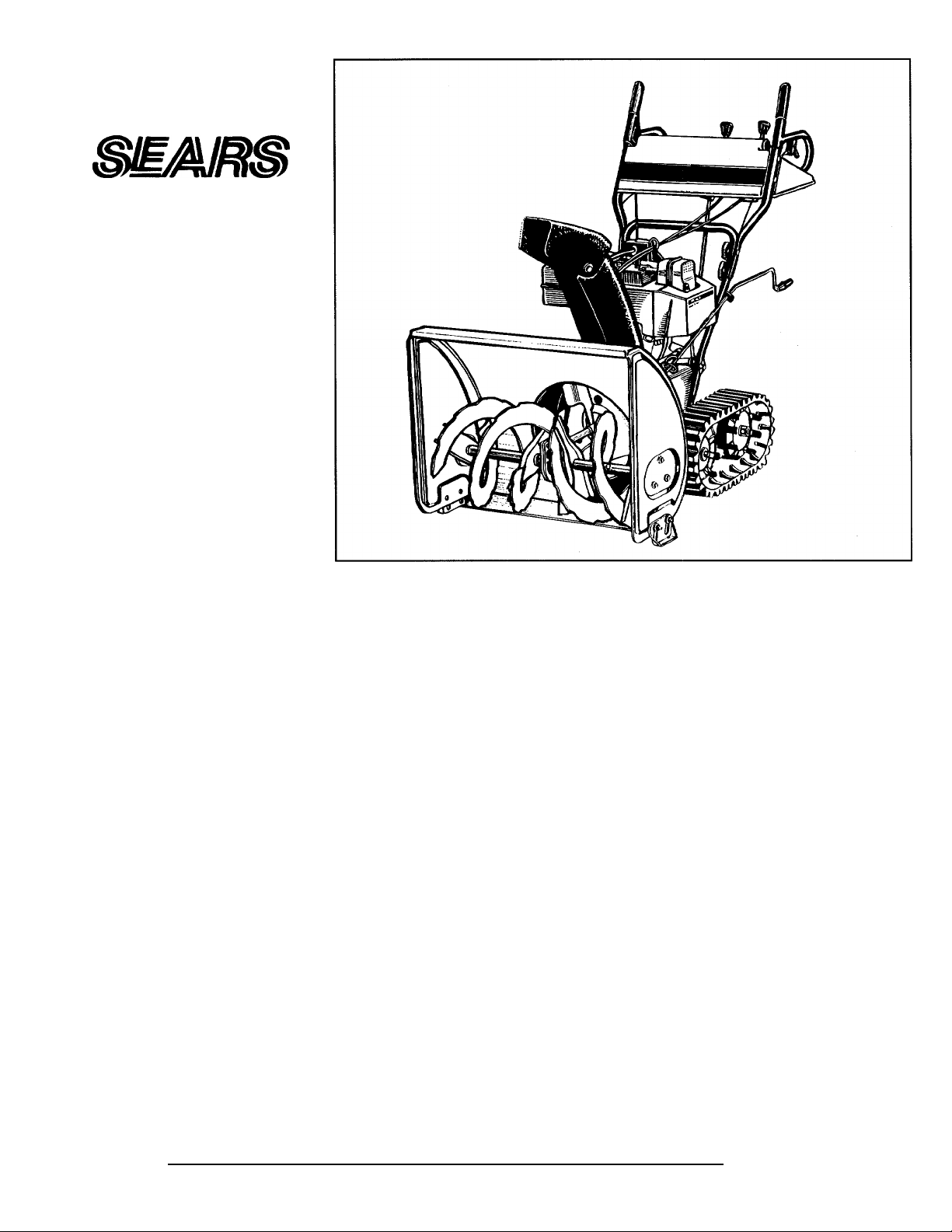
CRAFTSMAN
5 AND 8 HORSEPOWER
Caution:
Read and Follow
All Safety Rules
and Instructions
Before Operating
This Equipment
24" AND 26" WIDTH
TWO STAGE
TRACK DRIVE
SNOW THROWERS
Assembly
Operation
Customer Responsibilities
Service and Adjustment
Repair Parts
SEARS, ROEBUCKAND CO., Chicago, IL 60684 U.S.A.
______________
770-8738K
Page 2

S>VFETY RULES
WARNING: TO REDUCE THE POTENTIAL FOR ANY INJURY, COMPLY WITH THE FOLLOWING
A
SAFETY INSTRUCTIONS. FAILURE TO COMPLY WITH THE INSTRUCTIONS MAY RESULT IN
PERSONAL INJURY.
TRAINING
• Read this owner’s guide carefully in its entirety before attempting
A
A
**• Do not put hands or feet near or under rotating parts. Keep clear
to assemble or operate this machine. Be completeiy fc miliar with
the controls and the proper use of this machine beforn operating
it. Keep this manual in a safe place for future and regular refer
ence and for ordering replacement parts.
• Never allow children under 14 years old to operate a snow throw
er. Children 14 years old and over should only oprrate snow
thrower under close parental supervision. Only pe'sons well
acquainted with these rules of safe operation should be allowed
to use your snow thrower.
• No one should operate this unit while intoxicated or v hiie taking
medication that impairs the senses or reactions.
• Keep the area of operation clear of all persons, especially small
children and pets.
• Exercise caution to avoid slipping or falling, especially when
operating in reverse.
PREPARATION
• Thoroughiy inspect the area where the equipment is :o be used
and remove all door mats, sleds, boards, wires and otier foreign
objects.
• Disengage all clutches and shift into neutral befoie starting
engine.
• Do not operate equipment without wearing adequate v\ inter outer
garments. Do not wear jewelry, long scarfs or other loose cloth
ing which could become entangled in moving prrts. Wear
footwear which will improve footing on slippery surfac is.
• Before working with gasoline, extinguish all cigarettes and other
sources of ignition. Check the fuei before starting tie engine.
Gasoline is an extremely flammable fuel. Do not fill ti e gasoline
tank indoors, while the engine is running, or until i ngine has
been allowed to cool at least two minutes. Replace g; soline cap
securely and wipe off any spilled gasoline before s arting the
engine as it may cause a fire or explosion.
• Use a grounded three wire plug-in for all units with electric drive
motors or electric starting motors.
• Adjust collector housing height to clear gravel or cn shed rock
surface.
• Never attempt to make any adjustments while engine is running
(except where specifically recommended by manufactur :r).
• Let engine and machine adjust to outdoor temperatjre before
starting to ciear snow.
• Always wear safety glasses or eye shields during o[ eration or
while performing an adjustment or repair, to protect eyes from
foreign objects that may be thrown from the mach ne in any
direction.
OPERATION
of discharge opening and auger at all times.
• Exercise extreme caution when operating on or cros! ing gravel
drives, waiks, or roads. Stay alert for hidden hazards or traffic.
Do not carry passengers.
• After striking a foreign object, stop the engine, remove wire from
spark plug, and thoroughly inspect the snow throwir for any
damage. Repair the damage before restarting and operating the
snow thrower.
• If the snow thrower should start to vibrate abnormal!;', stop the
engine and check immediately for the cause. Vibration is general
ly a warning of trouble.
• Stop engine whenever you leave the operating position, before
unciogging the coilector/impelier housing or discharge guide,
and making any repairs, adjustments, or inspections. Never place
your hand in the discharge or collector openings. Use a stick or
wooden broom handle to unclog the discharge opening.
• Take all possible precautions when leaving the unit unattended.
Disengage the coilector/impelier, shift into neutral, stop the
engine, and remove the key.
• When cleaning, repairing, or inspecting, make certain
coilector/impelier and all moving parts have stopped. Disconnect
spark plug wire and keep away from plug to prevent accidental
starting.
• Do not run engine indoors, except when starting engine and
transporting snow thrower in or out of building. Open doors.
Exhaust fumes are dangerous.
• Do not clear snow across the face of slopes. Exercise extreme
caution when changing direction on slopes. Do not attempt to
clear steep slopes.
• Never operate snow thrower without guards, plates, or other
safety protection devices in place.
• Never operate snow thrower near glass enclosure, automobiles,
window wells, drop off, etc., without proper adjustments of snow
thrower discharge angle. Keep children and pets away.
• Do not overload machine capacity by attempting to clear snow at
too fast a rate.
• Never operate the machine at high transport speeds on slippery
surfaces. Look behind and use care when backing.
• Never direct discharge at bystanders or allow anyone in front of
unit.
• Disengage power to coilector/impelier when transporting or not
in use.
• Use only attachments and accessories approved by the manufac
turer of snow thrower (such as wheel weights, counter weights,
cabs, etc.).
• Never operate the snow thrower without good visibility or iight.
Always be sure of your footing and keep a firm hold on the han
dles. Walk, never run.
• Muffler and engine become hot and can cause a burn. Do not
touch.
MAINTENANCE AND STORAGE
Check shear bolts, engine mounting bolts, etc., at frequent inter
vals for proper tightness to be sure equipment is in safe working
condition.
• Never store the machine with fuel In the fuel tank inside a build
ing where ignition sources are present, such as hot water and
space heaters, clothes dryers, and the like. Allow engine to cool
before storing in any enciosure.
• Always refer to owner’s guide instructions for important details if
snow thrower is to be stored for an extended period.
• Run machine a few minutes after throwing snow to prevent
freeze up of coilector/impelier.
• Check clutch controls periodically to verify they engage and dis
engage properly and readjust if necessary. Refer to owner’s
guide for adjustment instructions.
A
LOOK FOR THIS SYMBOL TO POINT OUT
IMPORTANT SAFETY PRECAUTIONS. IT
MEANS—ATTENTION!!! BECOME ALERT!!!
YOUR SAFETY IS INVOLVED.
Page 3

CONGRATULATIONS on your purchase of a Sears
Craftsman snow thrower. It has been designed, engineered
and manufactured to give you the best possible dependabil
ity and performance.
Should you experience any problem you cannot easily rem
edy, please contact your nearest Sears Service Center/
Department in the United States. We have competent, welltrained technicians and the proper tools to service or repair
this unit.
Please read and retain this manual. The instructions will
enable you to assemble and maintain your snow thrower
properly. Always observe the “SAFETY RULES.”
PRODUCT SPECIFICATIONS
Horsepower: 5.0
Displacement: 13.53 cu. in.
Fuel Capacity:
Spark Plug
(Gap .030 in.):
2Qts.
(Unleaded)
J-8C or
Equivalent
8.0
19.43 cu. in.
1 Gal.
(Unleaded)
J-8C or
Equivalent
MODEL
NUMBER_
SERIAL
NUMBER_
DATE OF
PURCHASE,
THE MODEL AND SERIAL NUMBERS WILL BE FOUND
ON A LABEL ATTACHED TO THE FRAME OF THE
SNOW THROWER.
YOU SHOULD RECORD BOTH SERIAL NUMBER AND
DATE OF PURCHASE AND KEEP IN A SAFE PLACE
FOR FUTURE REFERENCE.
CUSTOMER RESPONSIBILITIES
• Read and observe the safety rules.
• Follow a regular schedule in maintaining, caring for
and using your snow thrower.
• Follow the instructions under “Customer
Responsibilities” and “Storage” sections of this
Owner’s Manual.
Ignition Air Gap:
.0125"
.0125"
MAINTENANCE AGREEMENT
A Sears Maintenance Agreement is available on this
product. Contact your nearest Sears store for details.
WARNING: This unit is equipped with an internal combus
tion engine and should not be used on or near any unim
proved forest-covered, brush-covered or grass-covered land
unless the engine’s exhaust system is equipped with a
spark arrester meeting applicable local or state laws (if any).
If a spark arrester is used, it should be maintained in effec
tive working order by the operator.
In the State of California the above is required by law
(Section 4442 of the California Public Resources Code).
Other states may have similar laws. Federal laws apply on
federal lands. A spark arrester for the muffler Is available
through your nearest Sears Authorized Service Center.
(See the REPAIR PARTS section of this manual.)
ONE YEAR LIMITED WARRANTY ON CRAFTSMAN GAS SNOW THROWER
For one year from the date of purchase, when this Craftsman Snow Thrower is maintained, lubricated and
tuned up according to the instructions in the owner’s manual, Sears will repair, free of charge, any defect in
material and workmanship.
If this Craftsman snow thrower is used for commercial or rental purposes, this warranty applies for only 30 days
from the date of purchase.
This warranty does not cover:
• Expendable items which become worn during normal use, such as skid shoes, shave plate and spark plugs.
• Repairs necessary because of operator abuse or negligence, including bent crankshafts and the failure to
maintain the equipment according to the instructions contained in the owner’s manual.
WARRANTY SERVICE IS AVAILABLE BY RETURNING THE CRAFTSMAN SNOW THROWER TO THE
NEAREST SEARS SERVICE CENTER/DEPARTMENT IN THE UNITED STATES. THIS WARRANTY
APPLIES ONLY WHILE THIS PRODUCT IS IN USE IN THE UNITED STATES.
This warranty gives you specific legal rights, and you may also have other rights which may vary from state to
state.
SEARS, ROEBUCK AND CO., D/817WA, Hoffman Estates, IL 60179
Page 4
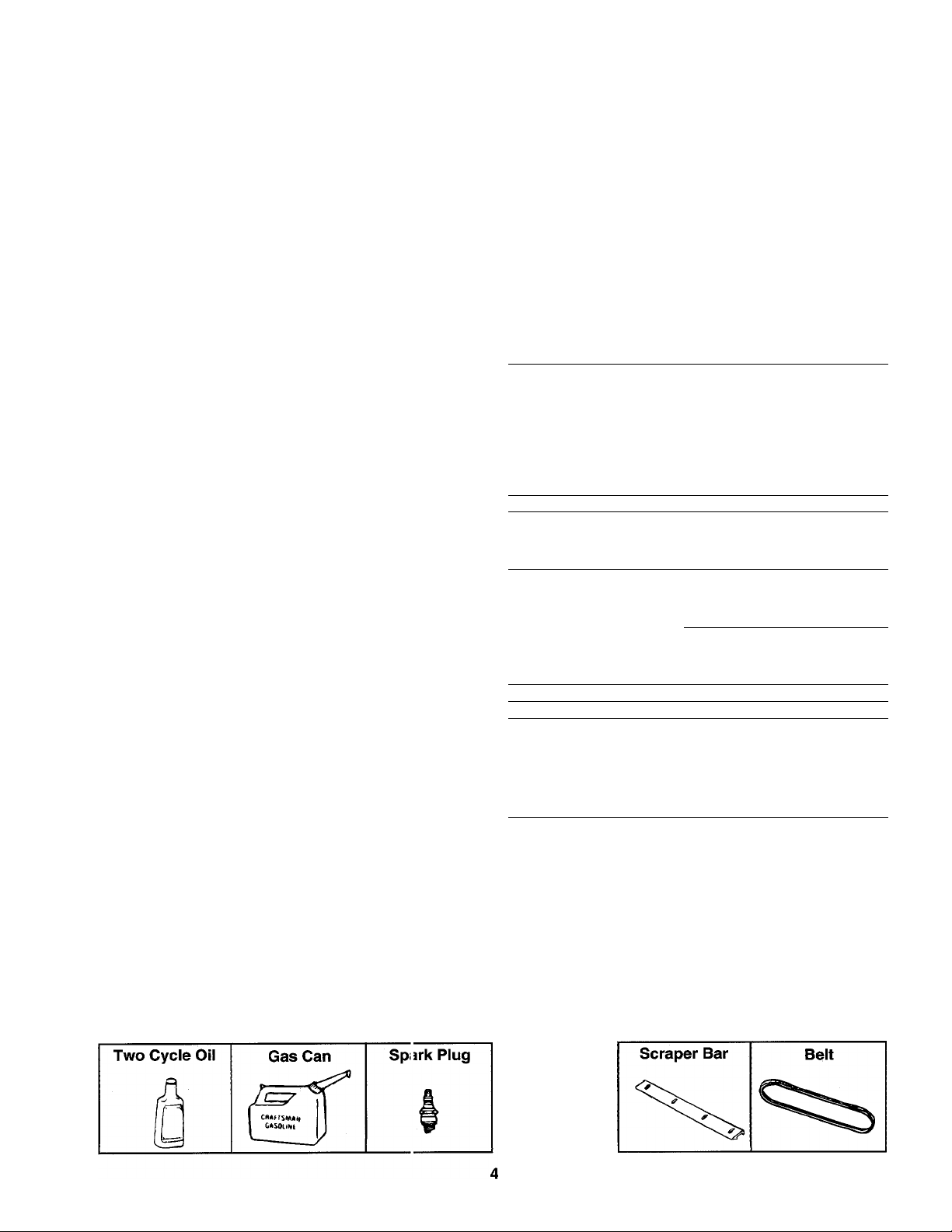
TABLE OF CONTENTS
11
SAFETY RULES........................................................2
PRODUCT SPECIFICATIONS..................................3
WARRANTY...............................................................3
INDEX........................................................................4
ASSEMBLY INSTRUCTIONS
...................................
OPERATION............................................................10
CUSTOMER RESPONSIBILITIES
Adjustments:
Auger Clutch...................
Carburetor
Shift Rod
Skid Shoes
Traction Drive Clutch
Assembly Instructions;
Chute...............................
Chute Crank
Clutch Cables
Final Adjustments
Handle.............................
Hardware Pack
Shift Rod
T rack Controis
Controls....................................
Customer Responsibilities.
Engine:
Lubrication
Maintenance
Starting................................
Stopping..............................
Storage
......................
.........................
......................
....................
..................
..........
..............
.........................
...............
..........................
.......................
................................
..........................
15
.....
.....
,.9, 20
.9, 17
,.9, 19
.10-11
.....
.13,16
.....
.....
......
.....
STORAGE
SERVICE AND ADJUSTMENT
TROUBLE SHOOTING
REPAIR PARTS—SNOW THROWER....................22
5
REPAIR PARTS—ENGINE
PARTS ORDERING/SERVICE
INDEX
Fuel.................................
20
20
15
16
14
12
17
Lubrication
Maintenance:
Oil....................................
Operating Tips
Repair/Replacement Parts.
Responsibilities, Customer.
Safety Rules
Spark Plug......................
Specifications..................
Storage
Table of Contents
Warranty
...............................................................
......................
Agreement
Schedule
Engine
.........................
...........................
........................
...................
.....................
................
...................
...........
...............................
...........................................
....................................
.............
F
BACK COVER
.....................
L
.....................
M
.......................
.....................
.....................
0
...............
.....................
R
.....................
.......................3
S
.......................
.....................
.......................3
.....................
T
.......................
w
.......................
17
17
21
31
13
15
3
15
16
13, 16
15
20
2
16
17
4
3
SNOW THFIOWER ACCESSORIES
These accessories were available when the snow thrower was purchased. They are also available at most Sears
retail outlets, catalog and service centers. Me st Sears stores can order repair parts for you, when you provide the
model number of your snow thrower.
ENGINE
SNOW THROWER MAINTENANCE
Page 5
ASSEMBLY INSTRUCTIONS
IMPORTANT: This unit has been shipped WITH
OUT GASOLINE or OIL. After assembly, see oper
ation section of this manuai for proper fuei and
engine oii recommendations.
NOTE: To determine right and left hand sides of your
snow thrower, stand behind it in the normai operating
position.
TO REMOVE SNOW THROWER FROM CARTON
Cut the corners of the carton. Remove ali packing
inserts. Roii snow thrower out of the carton. Make
certain ali parts and iiterature have been removed
before the carton is discarded.
Toois Required for Assembiy:
1/2" Wrench*
(2) 7/16" Wrenches*
Pair of Pliers
*or Adjustable Wrenches
Loose Parts in Carton:
(1) Handle Panel and Chute Assembly
(attached by cable)
(1) Right Hand Handle
(1) Left Hand Handle
(1) Chute Crank Assembly
(1) Shift Rod
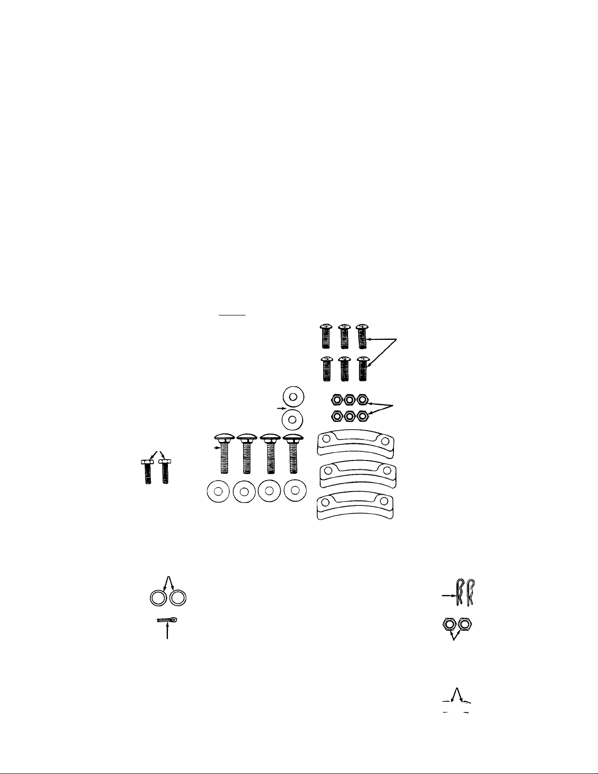
CONTENTS OF HARDWARE PACK
Lay out the hardware according to the illustration for identification purposes. Part numbers are shown in
parentheses.
ATTACHING THE HANDLE ASSEMBLY
Hex Bolts rr~nn—n
5/16-18x1-3/4" — ^
Long (710-3180)-
Hex Nuts*
1/4-20 Thread
(736-0287)
Hex Bolts
5/16-18x5/8"
Long (710-0538)
Lock
Washers
5/16" I.D.
(736-0119)
Hex Bolts*
1/4-20 X
7/8" Long
(710-0252)
Cupped Washers*
5/16" I.D.
(736-0242)
5/16-18 Thread (712-0267) _0
Q ATTACHING THE CHUTE CRANK
Flat Washers
3/8" I.D. X 5/8" O.D.
(736-0140)
Cotter Pin
(714-0507)
AUGER SHEAR BOLTS
The augers are secured to the spiral shaft with two hex bolts and hex
insert lock nuts. If you hit a foreign object or ice jam, the snow thrower is
designed so that the hex bolts will shear. Two replacement hex boits and
nuts are provided for your convenience. Store in a safe place until needed.
Carriage
Bolts'
5/16-18 X
1-1/2" Long
(710-1250)
mCA MUI9
Hex Nuts'
*May be preassembled on your unit.
Hex Bolt
5/16-18x1-1/2"
Long —>
(710-0442)
Lock Washer
5/16" I.D.
----------
6-0119)
(736-0119)
Hex Nut
5/16-18 Thread
(712-0267)
Cupped
Washers*
1/4” I.D.—
(736-0270)
Handle Tabs
(784-5599)
B ATTACHING THE CHUTE ASSEMBLY
Hex Bolts
1/4-20 X 3/4" Long
(710-3015)
Hex Lock Nuts
1/4-20 Thread
(712-3027)
' Chute Flange
Keepers
(731-0851)
□ ATTACHING THE SHIFT ROD
— AND CLUTCH CABLES
1 r~i hill Ferrule Hairpin Clips
[OJ_°|U-(711-0677) (714-0104)
Flat Washers
5/16" I.D. X 5/8" O.D.
(736-0264)
Spring Washer
5/16" I.D.
(736-0271)
CQatO)
Hex Bolts
-5/16-18x1-1/2"
Long
(710-0890)
Hex Nuts
(Come with
Clutch Cables)
Hex Lock Nuts
5/16-18 Thread
(712-0158)
^ (a
Page 6
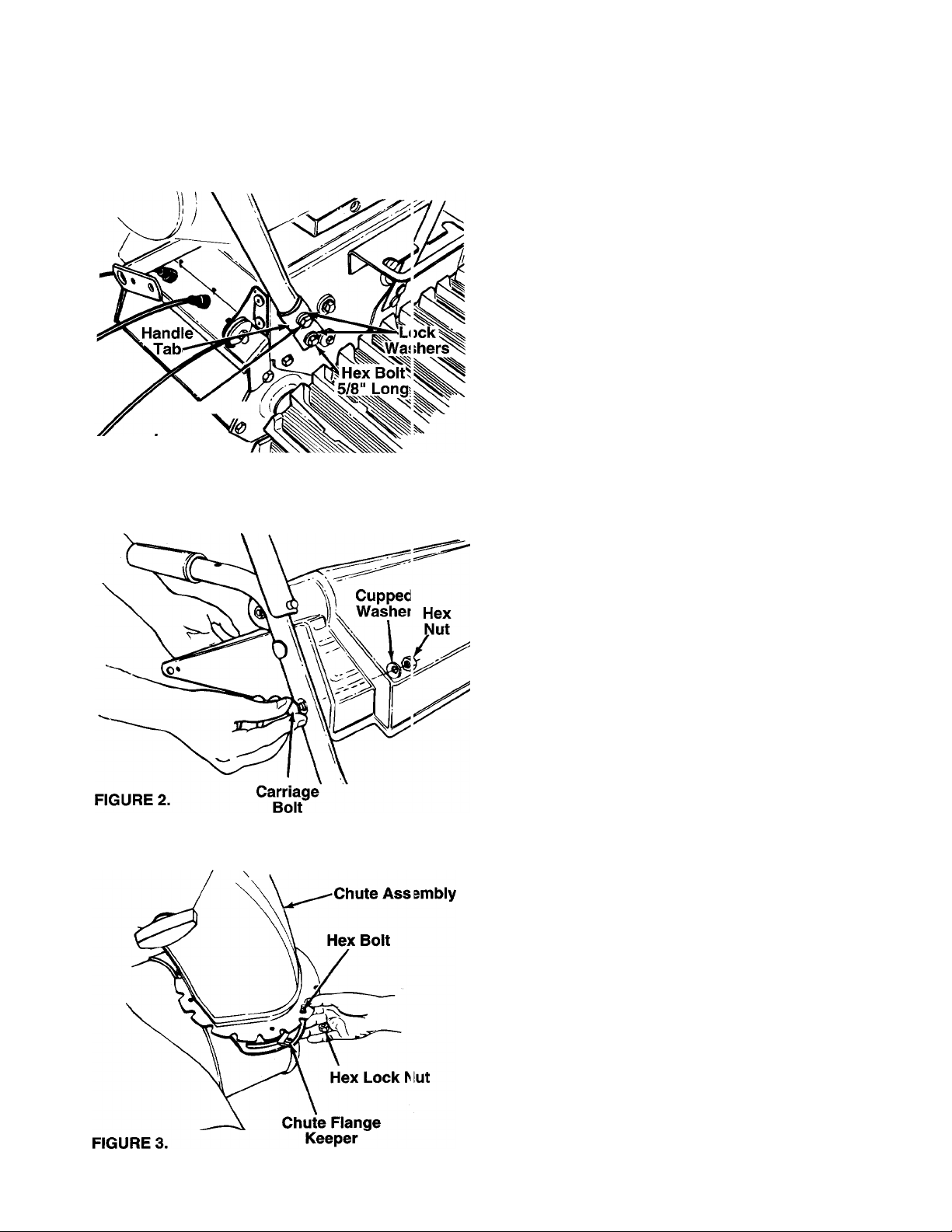
Bolt 1-3/4"
FIGURE 1.
Hex'^V /
Long
ASSEMBLY INSTRUCTIONS
HOW TO SET-UP YOUR SNOW THROWER
WARNING: MAKE CERTAIN THE
SPARK PLUG WIRE IS DISCONNECTED
AND MOVED AWAY FROM THE SPARK
A
ATTACHING THE HANDLE ASSEMBLY
(Hardware A)
• Stretch out control cables and place on the floor.
• Place right handle in position with flat side against
the snow thrower. Secure bottom holes in handle
to snow thrower using hex bolts 5/8" long and lock
— washers. See figure 1. Do not tighten at this time.
• Place handle tabs over the upper holes in handle,
so the curve in the handle tab matches the curve in
the handles. Secure to the snow thrower using hex
bolts 1-3/4" long and lock washers. Do not tighten
at this time.
• Attach the left handle in the same manner. Do not
tighten at this time.
• Place the handle panel in position between the
handles. Secure with four carriage bolts, cupped
washers (cupped side against the handie panel)
— and hex nuts as shown in figure 2.
• Tighten the four hex bolts used to attach the bot
tom of the handles to the snow thrower frame.
PLUG BEFORE ASSEMBLING THE
SNOW THROWER.
11
ATTACHING THE CHUTE ASSEMBLY
(Hardware B)
• Grease the chute opening using a multi-purpose
automotive grease or equivalent.
• Place chute assembly over chute opening, with the
opening in the chute assembly facing the front of
the unit. Place chute flange keepers beneath lip of
chute assembly. Insert hex bolt up through chute
flange keeper and chute assembly as shown in
— figure 3. Secure with hex lock nut. After assembling
all three chute flange keepers, tighten then back off
1/4 turn to allow easier movement.
Page 7
Lower
Chute
Crank
Bracket
ASSEMBLY INSTRUCTIONS
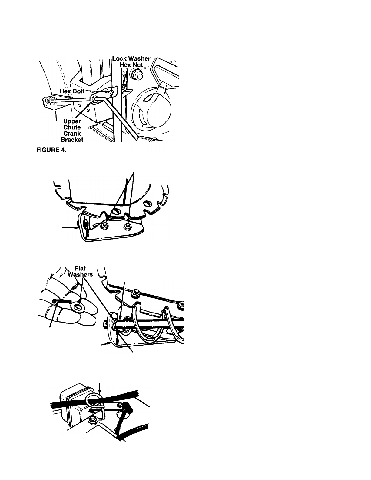
ATTACHING THE CHUTE CRANK (Hardware C)
• Insert hex bolt through the upper chute crank
— bracket. See figure 4.
• Place the hex bolt into the hole provided in the left
handle. Secure with lock washer and hex nut. Do
not tighten until after attaching the other end of the
chute crank.
Carriage Bolts
Hex Lock Nuts
• Loosen the carriage bolts and hex lock nuts which
secure the lower chute crank bracket to the exten
sion on the left side of the chute assembly. See
— figure 5.
FIGURE 5.
Cotter
Pin
FIGURE 6.
Lower
Chute Crank
Bracket
Guide
Cable
Chute
Crank
Plastic
Bushing
Place one flat washer on the end of the chute
crank, then insert the end of the crank into the hole
in the plastic bushing in the chute crank bracket.
See figure 6. Place the other flat washer on the end
of the chute crank, and insert cotter pin into hole in
the end of crank. Secure by bending the ends of
cotter pin in opposite directions.
Adjust the chute bracket so that the spiral on the
chute crank fully engages the teeth on the chute
assembly. Tighten the nuts on the lower chute
crank bracket securely. Tighten the hex bolt and
nut on the upper chute crank bracket on the
handle.
• Slip the cables that run from the handle panel to
the chute into the cable guide located on top of the
— engine. See figure 7.
FIGURE 7.
Page 8
11
ASSEME5LY INSTRUCTIONS
IMPORTANT: Attach the shift rod and ditch cables as follows. THEN CHECK THE ADJUSTMENTS AS
INSTRUCTED, AND MAKE ANY FINAL ADJUSTMENTS NECESSARY BEFORE OPERATING YOUR
SNOW THROWER. Failure to follow the in structlons may cause damage to the snow thrower.
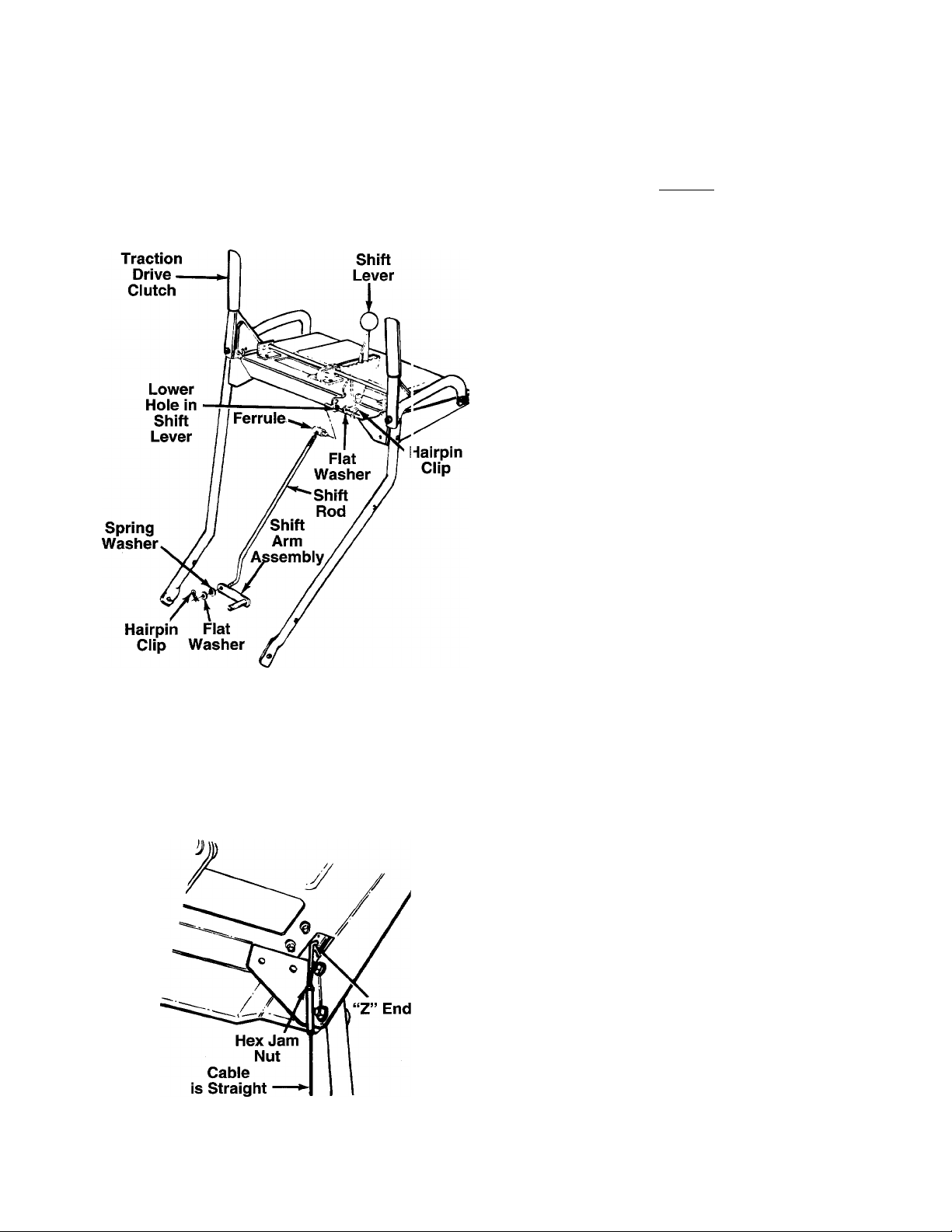
ATTACHING THE SHIFT ROD (Hardware D)
• Insert the ferrule through the lower hole in the shift
lever beneath the handle panel from the right side.
Secure with flat washer and hairpin clip. See figure
— 8.
• Place the shift lever in the sixth (6) speed position
(all the way forward).
• Start threading the shift rod into the ferrule. Push
down on the shift arm assembly as far as it will go.
Thread shift rod into the ferrule until the end of the
shift rod lines up with the hole in the shift arm
assembly. Secure with spring washer, flat washer
and hairpin clip.
Make certain to check for correct adjustment of the
shift rod as instructed in the Final Adjustment section
before operating the snow thrower.
FIGURE 8.
FIGURE 9.—Viewed from underside of han jle
panel.
ATTACHING THE CLUTCH CABLES
The “Z” ends of the clutch cables are hooked into the
clutch grips on each handle. Attach cables as follows.
• Thread the hex lock nuts (in hardware pack) ali the
way up the threaded portion of the “Z” ends of the
clutch cables.
• Make certain each cable is in groove of cable roller
guides. Place the clutch grip in the raised (up) posi
tion.
• Thread the cable onto the threaded portion of the
“Z” and until there is no slack in the cable, but the
cable Is NOT tight. Do not overtighten cable.
— See figure 9.
A
• When correct adjustment is reached, tighten the
hex nut against the bottom portion of the cable to
lock it in position.
•
WARNING: IF CABLE IS TIGHTENED SO
THERE IS TENSION ON THE CABLE
WITH THE CLUTCH GRIP RELEASED,
THE SAFETY FEATURES OF THE SNOW
THROWER MAY BE OVERRIDDEN.
Page 9
ASSEMBLY INSTRUCTIONS
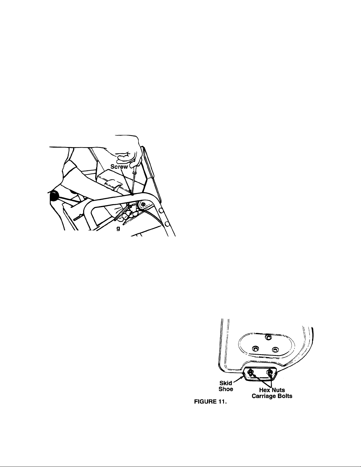
ATTACHING THE LEFT AND RIGHT TRACK
CONTROLS
• Remove the screw from the top of the right hand
track control. Be careful not to lose the flat weld nut
that is inside the control.
• Place the right track control in position underneath
the right handle. Secure with screw just removed.
See figure 10.
• Secure the left track control in the same manner.
Traction Drive Ciutch and Shift Lever Adjustment
To check the adjustment of the traction drive clutch
and shift lever, tip the snow thrower forward so that it
rests on the auger housing. First move the shift lever
all the way forward to sixth (6th) position. With the
traction drive lever released, turn the snow thrower
tracks by hand. They should turn freely. Then engage
the traction drive clutch grip and try to turn the tracks.
The tracks should not move.
Now release the traction drive clutch grip, and turn the
tracks again. Move the shift lever back to the fast
reverse position, then all the way forward again.
There should be no resistance in the shift lever, and
you should be able to turn the tracks by hand.
If you have resistance when moving the shift lever or
you are unable to turn the tracks by hand, loosen the
lock nut on the traction drive cable and unthread the
cable one turn. If you are able to turn the tracks when
you engage the traction drive clutch grip, loosen the
lock nut on the traction drive cable and thread the
cable in one turn. Recheck the adjustment and repeat
adjustment as necessary. Tighten the lock nut to
secure the cable when correct adjustment is reached.
Right
Track
FIGURE 10.
Control
FINAL ADJUSTMENTS
Auger Drive Ciutch
To check the adjustment of the auger drive clutch,
push fonward on the left hand clutch grip (depress the
rubber bumper). There should be slack in the cable.
Release the clutch grip. The cable should be straight.
Make certain you can depress the auger drive clutch
grip against the left handle completely.
If necessary, loosen the hex jam nut and thread the
cable in or out as necessary. Refer to figure 9.
Recheck the adjustment. Tighten the jam nut against
the cable when correct adjustment is reached.
Adjusting the Skid Shoes
The space between the shave plate and the ground
can be adjusted. For close snow removal, place skid
shoes in the low position. Use middle or high position
when area to be cleared is uneven. See figure 11.
Adjust skid shoes by loosening the four hex nuts and
carriage bolts and moving skid shoes to desired posi
tion. Make certain the entire bottom surface of skid
shoe is against the ground to avoid uneven wear on
the skid shoes. Retighten nuts and bolts securely.
Page 10
11
OPERATION
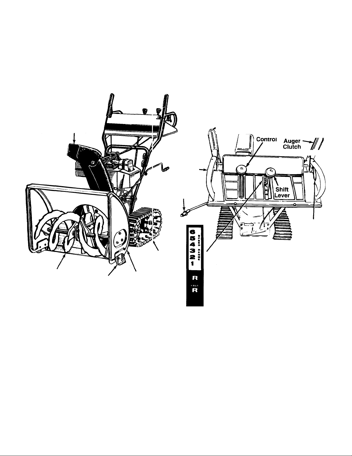
KNOW YOUR SNOW THROWER
READ THIS OWNER’S MANUAL AND SAFETY RULES BEFORE OPERATING YOUR SNOW THROWER.
Compare the illustrations with your snow thrower to familiarize yourself with the location of various controls and
adjustments. Save this manual for future refenmce.
Auger
Discharge
Chute
Skid
Shoe
Auger
Housing
Track
Left
Track
Control
Chute
Crank
Auger
.Drive
t Clutch
Chute Traction
Tilt . Drive/
Lock
Right
Track
Control
FIGURE 12.
MEETS ANISI SAFETY REQUIREMENTS
Sears snow throwers conform to the safety standards of the American National Standards Institute.
OPERATING CONTROLS
SHIFT LEVER (See figures 12)
The shift lever is located in the center of the handle
panel. The shift lever may be moved into one of eight
positions. Run engine with throttle in the fast position.
Use the shift lever to determine ground speed.
Forward—one of six speeds. Position number one (1)
is the slowest. Position number six (6) is the fastest.
Reverse—^two reverse (R) speeds. “R” closest to the
operator (all the way back) is the faster of the t^ro.
AUGER DRIVE CLUTCH (See figure 12)
The auger drive clutch is located on the left handle.
Squeeze the auger drive clutch against the handle to
engage the augers. Release to stop the snow throw
ing action. (Traction drive clutch must also be
released.)
10
Page 11
OPERATION
TRACTION DRIVE/AUGER CLUTCH LOCK
(See figure 12)
The traction drive clutch is located on the right handle.
Squeeze the traction drive clutch to engage the wheel
drive. Release to stop.
This same lever also locks the auger clutch so you
can turn the chute crank without interrupting the snow
throwing process. If the auger drive clutch is engaged
with the traction drive clutch engaged, the operator
can release the auger drive clutch (on the left handle)
and the augers will remain engaged. Release the
traction drive clutch to stop both the augers and wheel
drive (auger drive ciutch must aiso be released).
CHUTE CRANK (See figure 12)
The chute crank is located on left hand side of the
snow thrower.
To change the direction in which snow is thrown, turn
chute crank as follows:
1. Crank clockwise to discharge to the left.
2. Crank counterclockwise to discharge to the right.
THROTTLE CONTROL (See figure 14)
The throttle control is located on the engine. It regu
lates the speed of the engine.
LEFT AND RIGHT TRACK CONTROLS
The left and right track controls are located on the
underside of the handles and are used to assist in
steering your snow thrower. See figure 12. Squeeze
the right track control when turning right, squeeze the
left control when turning left. Operate your snow
thrower in open areas until you become familiar with
these controls.
CHUTE TILT CONTROL
The distance snow is thrown can be adjusted by
adjusting the angle of the chute assembly. Move the
chute tilt control forward to decrease the distance,
toward the rear to increase. See figure 12.
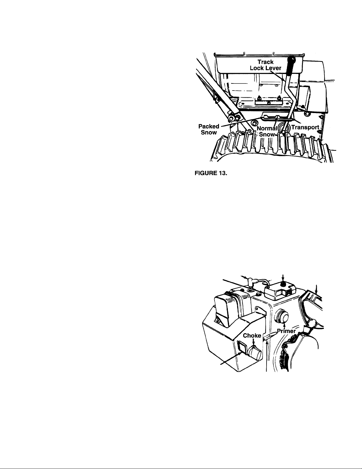
TRACK LOCK LEVER
The track lock lever is located on the right side of the
snow thrower and is used to select the position of the
housing and the method of track operation. See figure
13. Move the lever to the right, then forward or back
ward to one of the three positions.
Transport—Raises the front end of the snow thrower
for easy transport. May also be used on gravel drive
ways to clear snow and leave gravel undisturbed.
Normal Snow—Allows the tracks to be suspended
independently for continuous ground contact.
Packed Snow—Locks the front end of the snow
thrower down to the ground for hard-packed or icy
snow conditions.
SAFETY IGNITION SWITCH (See figure 14)
The ignition key must be inserted in the switch before
the unit will start. Remove the ignition key when snow
thrower is not in use.
Spark
Plug
Switch
Box
Ignition
Key
FIGURE 14.
HEAD LAMP (8 H.P. Only)
Throttle
Control
Starter
Button
Rope Starter
Handle
The head lamp is on whenever the engine is running.
11
Page 12
11
(OPERATION
BEFORE USING YOUR SNOW THROWER, AGAIN REFER TO THE “SAFETY RULES” AS SHOWN ON PAGE
2 OF THIS MANUAL ALWAYS BE CAREFUL.
The operation of any snow thrower can result in foreign objects being thrown into the
eyes, which can result in severe eye damage. Always wear safety glasses or eye
shields before startin'3 power tool operation or while performing any adjustments or
repairs. We recommtsnd Wide Vision Safety Mask for over spectacles or standard
safety glasses available at Sears Retail or Catalog Stores.
TO STOP ENGINE
• Remove the ignition key from the carburetor cover
on the engine (do not turn). See figure 14.
• Disconnect spark plug wire and move away from
spark plug to prevent accidental starting while
equipment is unattended.
HOW TO USE YOUR SNOW THROWE R
The snow thrower is propelled by the two trach s.
TO ENGAGE DRIVE
• With the engine running near top speed, move shift
lever into one of the six FORWARD positions or
two REVERSE positions. Select a speed appropri
ate for the snow conditions that exist. Use the slow
er speeds until you are familiar with the operation
of the snow thrower.
• Squeeze the left hand auger drive clutch to engage
it.
• While the left handle auger drive clutch is e igaged,
engage the right hand traction drive/auger clutch
lock.
• Release the left hand auger drive clutch only. The
interlock mechanism should keep the left hand
auger drive clutch engaged until the riglit hand
traction drive/auger clutch lock is released.
Release it and the drive motion will stop.
NOTE: NEVER move shift lever without first releasing
the drive clutch.
• Set the track lock lever in one of the throe posi
tions: transport, normal snow or packed snow. See
figure 13.
• Move the tilt control to the rear to increase the dis
tance.
BEFORE STARTING
OIL
• Only use high quality detergent oil rated with API
service classification SF or SG. Use SAE 5W-30
oil.
• SAE low is an acceptable substitute. (Do not use
10W-40).
• Oil sump capacity:
5 H.P. Engine 1-1/4 pints (19 ounces)
8 H.P. Engine 1-5/8 pints (26 ounces)
• Maintain oil level between “FULL” and “ADD”
marks on dipstick.
• Remove oil fill plug and dipstick.
• Wipe dipstick clean, insert it into oil fill hole and
tighten securely. Remove dipstick. If oil is not up to
“FULL” mark on dipstick, add recommended oil.
POUR SLOWLY. Wipe dipstick clean each time oil
level is checked.
IMPORTANT: DO NOT FILL ABOVE “FULL”
MARKON DIPSTICK.
• Install oil fill plug and dipstick. Tighten securely.
Oil Fill
DISCHARGE CHUTE
The direction snow is thrown can be changed by turn
ing the chute control crank.
• Turn clockwise to discharge to the left.
• Turn counterclockwise to discharge to the right.
The distance snow is thrown can be chargecLby
adjusting the upper chute tilt control.
• Move the tilt control forward to decrease the dis
tance..
12
Page 13

OPERATION
GAS
• Remove fuel cap and fill fuel tank with about 3
quarts of clean, fresh, lead-free grade automotive
gasoline. DO NOT use Ethyl or high octane gaso
line. Be certain container is clean and free from
rust or foreign particles. Never use gasoline that
may be stale from long periods of storage in the
container. Replace fuel cap.
WARNING: DO NOT FILL CLOSER
THAN 1/2 INCH OF TOP OF FUEL TANK
TO PREVENT SPILLS AND TO ALLOW
A
Check the fuel level periodically to avoid running out
of gasoline while operating the snow thrower. If the
unit runs out of gas, it may be necessary to unclog the
unit before it can be restarted. Refer to Service and
Adjustment section.
WARNING: EXPERIENCE INDICATES THAT ALCO
HOL BLENDED FUELS (CALLED GASOHOL OR
USING ETHANOL OR METHANOL) CAN ATTRACT
MOISTURE WHICH LEADS TO SEPARATION AND
FORMATION OF ACIDS DURING STORAGE.
ACIDIC GAS CAN DAMAGE THE FUEL SYSTEM
OF AN ENGINE WHILE IN STORAGE. TO AVOID
ENGINE PROBLEMS, THE FUEL SYSTEM
SHOULD BE EMPTIED OR TREATED WITH FUEL
STABILIZER BEFORE STORAGE FOR 30 DAYS
OR LONGER. USE FRESH FUEL NEXT SEASON.
SEE “STORAGE” SECTION FOR ADDITIONAL
INFORMATION.
NEVER USE ENGINE OR CARBURETOR CLEAN
ER PRODUCTS IN THE FUEL TANK OR PERMA
NENT DAMAGE MAY OCCUR.
FOR FUEL EXPANSION. IF GASOLINE
IS ACCIDENTLY SPILLED, MOVE SNOW
THROWER AWAY FROM AREA OF
SPILL. AVOID CREATING ANY SOURCE
OF IGNITION UNTIL GASOLINE
VAPORS HAVE DISAPPEARED.
TO START ENGINE
USING THE ELECTRIC STARTER
• Make certain the auger control handle is disen
gaged (released).
• Insert ignition key into ignition switch. Do not turn.
• To start a cold engine, move choke lever to ON
position. If you are starting an engine which has
already been run for a few minutes, do not choke.
• To start a cold engine, push primer button one
time. Use a firm push. This step is not necessary
when starting an engine which has been run for a
few minutes.
• Connect power cord to plug on snow thrower, then
to a three-hole, grounded 120-volt AC household
outlet.
WARNING: ALWAYS CONNECT POWER
CORD TO PLUG ON SNOW THROWER
FIRST, THEN PLUG THE OTHER END IN
A
• Push starter button to engage starter motor and
crank engine.
IMPORTANT: THIS ELECTRIC STARTER IS NOT
NOTE: If the starter motor runs but the engine does
not turn over, the starter gear is apparently covered
with ice and frozen. Place the unit in a warm atmo
sphere until the gear is free and the starter will
engage.
• After engine starts, release starter button. Allow the
engine to warm up for a few minutes. Then move
choke gradually to OFF position. If engine falters,
return to ON position, then slowly move to OFF
position.
• Unplug the power cord from the household outlet,
then from the plug on snow thrower.
USING THE RECOIL STARTER
• Make certain auger control handle is disengaged
(released).
• Insert Ignition key into ignition switch. Do not turn.
• To start a cold engine, move choke lever to ON
position. If you are starting an engine which has
already been run for a few minutes, do not choke.
• To start a cold engine, push primer button two or
three times. Use a firm push. This step is not nec
essary when starting an engine which has been run
for a few minutes.
THE HOUSEHOLD OUTLET. WHEN DIS
CONNECTING, ALWAYS UNPLUG
FROM THE HOUSEHOLD OUTLET
FIRST.
EQUIPPED WITH A THERMAL
CUTOUT SWITCH. DO NOT CRANK
ENGINE FOR MORE THAN A TOTAL
OF 20 SECONDS WITHOUT ALLOW
ING ELECTRIC STARTER TO COOL
DOWN FOR 10 MINUTES, OR
SEVERE DAMAGE TO ELECTRIC
STARTER CAN RESULT.
13
Page 14

OPERATION
NOTE: If the temperature is below 15°F., additional
priming may be necessary for initial start only.
• Grasp starter handle and pull rope out slov/ly, until
it pulls slightly harder. Let rope rewind slowl /.
• Pull starter handle rapidly. Keep a firm hold on the
handle and allow it to rewind siowly. Do nst allow
handle to snap back.
• If engine fails to start after 3 pulls on the starter
handle, prime engine two times and pull starter
handle again.
• After engine starts and begins to operate evenly,
move choke lever gradually to OFF position. If
engine falters, return to ON position, theri slowly
move to OFF position.
WARNING: TEMPERATURE OF MUF
FLER AND SURROUNDING AREAS MAY
A
EXCEED 150°F. AVOID THESE AREAS.
A da n ge r VA d an g er
l4
AVOID INJURY FROM
STOP THE ENGINE
BEFORE UNCLOGGING
OISCHARGE CHUTE!
OPERATING TIPS
• Use your snow thrower to remove fresh snow
before it is packed down by footprints or tire tracks.
• Discharge snow in the direction the wind is blowing
whenever possible.
• Slightly overlap each previous swath.
• Snow up to about an 8 inch depth can be removed
easily by walking at a moderate rate. Slow your
pace for wet or deep snow.
• Run engine for a few minutes before stopping to
help dry off any moisture on the engine.
ROTATING AUGER-
KEEP HANDS, FEET,
AND CLOTHING AWAY!
14
Page 15

CUSTOMER RESPONSIBILITIES
V
CHECK
GENERAL RECOMMENDATIONS
WARNING: ALWAYS STOP THE ENGINE
AND DISCONNECT THE SPARK PLUG
WIRE BEFORE PERFORMING ANY
A
MAINTENANCE OR ADJUSTMENTS.
• Periodically check all fasteners and be sure they
are tight.
• Follow the Maintenance Schedule above.
LUBRICATION
Gear Shaft
Lubricate the gear shaft with grease at least once a
season or after every 25 hours of operation.
IMPORTANT: Keep all grease and oil off of the
friction wheel and drive plate.
Shifting Mechanism
Lubricate the shifting mechanism and pivot points on
the shift rod with engine oil at least once a season or
after every 25 hours of operation.
Traction Drive/Auger Ciutch Lock
The cams on the ends of the control rods which inter
lock the traction drive and auger drive clutches must
be lubricated at least once a season or every twentyfive hours of operation with grease. The cams can be
accessed beneath the handle panel.
Gear Case
The gear case is lubricated with grease at the factory
and does not require checking. If disassembled for
any reason, lubricate with 2 ounces of Shell Alvania
grease, part number 737-0168.
Bearings
Lubricate the auger bearings, wheel bearings and the
bearings on the side of the frame once a season with
light oil.
15
Page 16

CUSTOMER RESPONSIBILITIES
AUGERS
The augers are secured to the spiral shaft \
hex bolts and hex lock nuts. See figure 16. If 5
foreign object or ice jam, the snow thr(
designed so that the hex bolts will shear.
If the augers will not turn, check to see if the h
have sheared. Two replacement hex bolts ;
lock nuts have been provided with the snow
For future use, order part number 710-0890 (
5/16-18 X 1.5" long) and 712-0429 (hex insert
5/16-18 thread).
\rith two
ou hit a
)wer is
ex bolts
ind hex
:h rower,
lex bolt
lock nut
tighten securely. Remove dipstick. If oil is not up to
“FULL” mark on dipstick, add recommended oil.
POUR SLOWLY. Wipe dipstick clean each time oil
level is checked.
IMPORTANT: DO NOT FILL ABOVE “FULL” MARK
ON DIPSTICK.
• Install oil fill plug and dipstick, tighten securely.
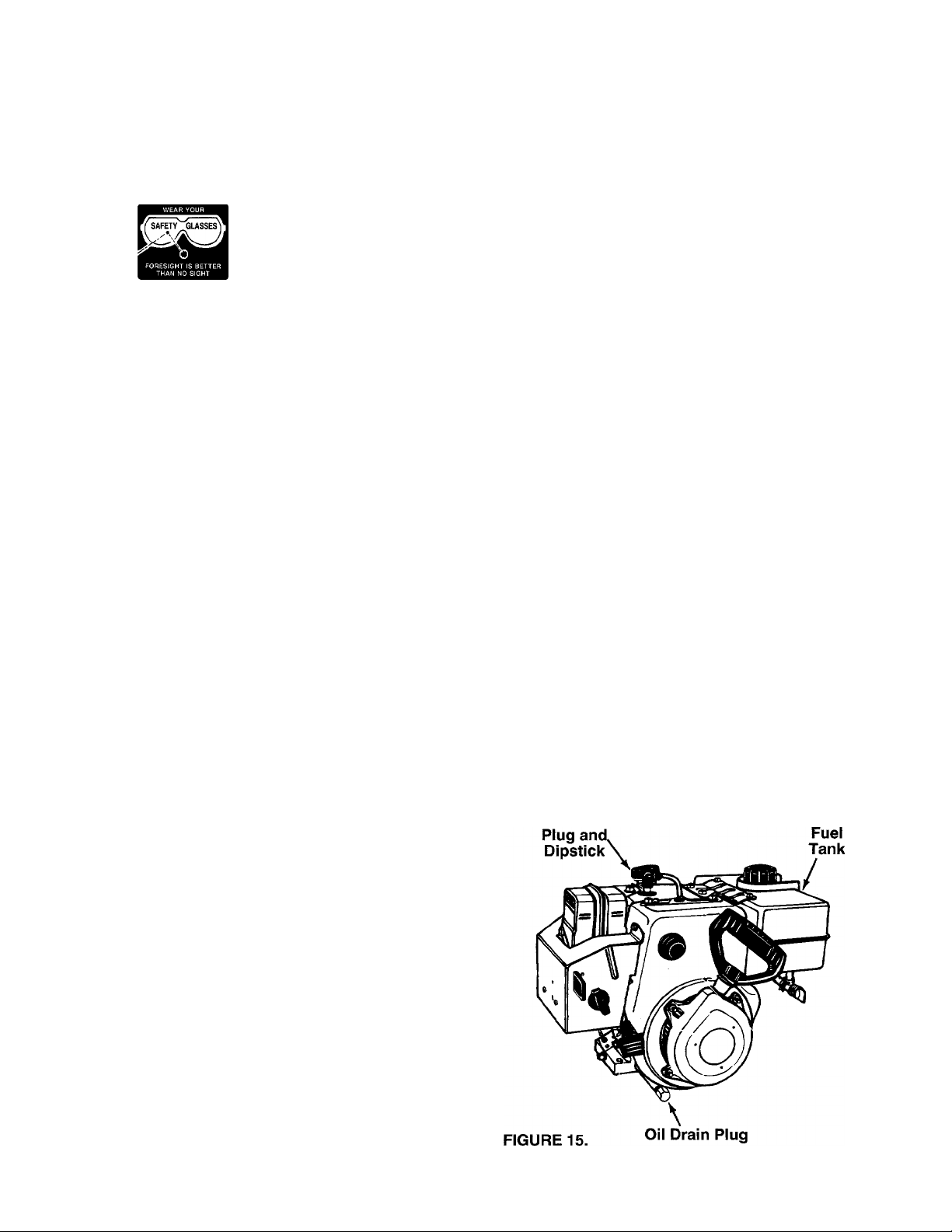
To Drain Oil:
• Drain oil while engine is warm.
a. Remove oil drain plug. Refer to figure 15. Catch
oil in a suitable container.
b. When engine is drained of ail oil, replace drain
plug securely.
• Refill with fresh oil. Refer to before starting in the
operation section.
• Replace dipstick.
SPARK PLUG
The spark plug should be cleaned and the gap reset
to .030" at least once a season or every 50 hours of
operation. See figure 17. Spark plug replacement is
recommended at the start of each season. Refer to
engine parts list for correct spark plug type.
NOTE: Do not sandblast spark plug. Spark plug
should be cleaned by scraping or wire brushing and
washing with a commercial solvent.
ENGINE
ENGINE OIL
• Only use high quality detergent oil rated v/ith API
service classification SF or SG. Use SAE 5W-30
oil.
• SAE low is an acceptable substitute. (Do not use
10W-40).
• Oil sump capacity:
5 H.P. Engine 1-1/4 pints (19 ounces)
8 H.P. Engine 1-5/8 pints (26 ounces)
• Maintain oil level between “FULL” and "ADD”
marks on dipstick.
• Remove oil fill plug and dipstick.
• Wipe dipstick clean, insert it into oil fill hale and
FIGURE 17.
16
Page 17

STORAGE
Prepare your snow thrower for storage at the end of
the season or if the unit will not be used for 30 days or
more.
WARNING: NEVER STORE MACHINE
WITH FUEL IN THE FUEL TANK INSIDE
OF BUILDING WHERE FUMES MAY
A
NOTE: A yearly check-up by your local Sears Service
REACH AN OPEN FLAME OR SPARK,
OR WHERE IGNITION SOURCES ARE
PRESENT SUCH AS HOT WATER AND
SPACE HEATERS, FURNACES,
CLOTHES DRYERS, STOVES, ELEC
TRIC MOTORS, ETC.
Center is a good way to make certain your snow
thrower will provide maximum performance for the
next season.
SNOW THROWER
• Clean the snow thrower thoroughly.
• Wipe unit with an oiled rag to prevent rust (use a
light oil or silicone).
ENGINE
IMPORTANT: IT IS IMPORTANT TO PREVENT
GUM DEPOSITS FROM FORMING IN ESSENTIAL
FUEL SYSTEM PARTS SUCH AS CARBURETOR,
FUEL FILTER, FUEL HOSE, OR TANK DURING
STORAGE. ALSO, EXPERIENCE INDICATES THAT
ALCOHOL BLENDED FUELS (CALLED GASOHOL
OR USING ETHANOL OR METHANOL) CAN
ATTRACT MOISTURE WHICH LEADS TO SEPARA
TION AND FORMATION OF ACIDS DURING STOR
AGE. ACIDIC GAS CAN DAMAGE THE FUEL SYS
TEM OF AN ENGINE WHILE IN STORAGE.
• Drain the fuel tank.
• Start the engine and let it run until the fuel lines and
carburetor are empty.
• Never use engine or carburetor cleaner products in
the fuel tank or permanent damage may occur.
• Use fresh fuel next season.
NOTE: Fuel stabilizer is an acceptable alternative in
minimizing the formation of fuel gum deposits during
storage. Add stabilizer to gasoline in fuel tank or stor
age container. Always follow the mix ratio found on
stabilizer container. Run engine at least 10 minutes
after adding stabilizer to allow the stabilizer to reach
the carburetor. Do not drain the gas tank and carbure
tor if using fuel stabilizer.
• Drain all the oil from the crankcase (this should be
done after the engine has been operated and is still
warm) and refill the crankcase with fresh oil.
• If you have drained the fuel tank, protect the inside
of the engine as follows. Remove spark plug, pour
approximately 1/2 ounce (approximately one table
spoon) of engine oil into cylinder and crank slowly
to distribute oil. Replace spark plug.
OTHER
• Do not store gasoline from one season to another.
• Replace your gasoline can if your can starts to rust.
Rust and/or dirt in your gasoline will cause prob
lems.
• Store unit in a clean, dry area. Do not store next to
corrosive materials, such as fertilizer.
NOTE: If storing in an unventilated or metal storage
shed, be certain to rustproof the equipment by coating
with a light oil or silicone.
SERVICE & ADJUSTMENT
WARNING: ALWAYS STOP ENGINE
AND DISCONNECT SPARK PLUG WIRE
AND MOVE IT AWAY FROM SPARK
A
SHAVE PLATE AND SKID SHOES
• The shave plate and skid shoes on the bottom of
the snow thrower are subject to wear. They should
be checked periodically and replaced when neces
sary.
PLUG BEFORE PERFORMING ANY
ADJUSTMENTS OR REPAIRS.
• To remove skid shoes, remove the four carriage
bolts, belleville washers and hex nuts which attach
them to the snow thrower. Reassemble new skid
shoes with the four carriage bolts, belleville wash
ers (cupped side goes against skid shoes) and hex
nuts. Make certain the skid shoes are adjusted to
be level.
• To remove shave plate, remove the carriage bolts,
belleville washers and hex nuts which attach it to
the snow thrower housing. Reassemble new shave
plate, making sure heads of the carriage bolts are
to the inside of the housing. Tighten securely.
17
Page 18

SERVICE & ADJUSTMENT
BELT REMOVAL AND REPLACEMENl
WARNING: DISCONNECT THE SPARK
PLUG WIRE FROM THE SPARK PLUG
A
AND GROUND.
11
To remove and replace either the rear or front auger
drive belt, proceed with the following instructions.
• Disconnect the chute crank at the chute assembly
by removing the cotter pin and flat washer.
• Remove the plastic belt cover on the front of the
engine by removing two self-tapping screu/s. See
figure 18.
Self Tapping
Screws
FIGURE 19.
Frame
Hex Bolts
Lock Washers
Hex Nuts
Auger
Assembly
Auger
Hous ng
FIGURE 18.
Unthread the bottom of the auger cable fiom the
top of the cable, leaving the hex nut in place.
Remove the six hex bolts, lock washers end hex
nuts which attach the auger housing asse nbly to
the frame. See figure 19.
Separate the housing from the frame assembly by
standing in the operating position and lifting up on
the handles. The frame and housing will se parate,
and the rear auger drive belt will come off he pul
leys. See figure 20.
To remove the front auger drive belt, push tne idler
pulley to the left, and lift front auger drive b 3lt from
the front auger pulley. See figure 21. Replace both
auger drive belts by following instruct ons in
reverse order.
FIGURE 20.
Frame
Front
Auger
Drive
Belt
FIGURE 21.
18
Page 19

SERVICE & ADJUSTMENT
• If a replacement drive belt is needed, follow
previous instructions. Pull idler pulley up and lift
belt off friction wheel disc. See figure 22.
Reassemble in reverse order.
NOTE: When reassembling the two halves of the unit,
the auger drive cable must be routed through the
cable roller guides as shown in figure 22.
Idler
Pulley
• Remove the six screws from the friction wheel
assembly (three from each side). Remove the fric
tion wheel rubber from between the friction wheel
plate.
• Reassemble new friction wheel rubber to the fric
tion wheel assembly, tightening the six screws in
rotation and with equal force.
• Slide the friction wheel assembly up onto the shift
mechanism as shown in figure 24, and slide the
gear shaft back into the unit. Reassemble in
reverse order.
FIGURE 22.
CHANGING THE FRICTION WHEEL RUBBER
The rubber on the friction wheel is subject to wear
and should be checked after 25 hours of operation,
and periodically thereafter. Replace the friction wheel
rubber if any signs of wear or cracking are found.
• Drain the gasoline from the snow thrower, or place
a piece of plastic under the gas cap.
• Tip the snow thrower up and forward, so that it
rests on the housing.
• Remove four self-tapping screws from the frame
cover underneath the snow thrower.
• Remove the gear shaft from the unit by removing
N
the bolts, lock washers and flat washers from each
side of the frame. See figure 23. Hold the friction
wheel assembly, and slide the gear shaft out of the
unit toward the right hand side. Refer to figure 24.
TRACTION DRIVE CLUTCH ADJUSTMENT
Refer to the Final Adjustment section of the Assembly
Instructions to adjust the traction drive clutch. If you
are uncertain that you have reached the correct
adjustment, the adjustment can be physically checked
as follows.
With the snow thrower tipped fonward (be certain to
drain the gasoline or place plastic film under the gas
cap if the snow thrower has already been operated),
remove the frame cover underneath the snow thrower
by removing four self-tapping screws. With the trac
tion drive clutch released, there must be clearance
between the friction wheel and the drive plate in all
positions of the shift lever. With the traction drive
clutch engaged, the friction wheel must contact the
drive plate. See figure 24.
19
Page 20

SERVICE & ADJUSTMENT
11
If adjustment is necessary, loosen the lock nut on the
traction drive cable and thread the cable in o ■ out as
necessary. Tighten the lock nut to secure the cable
when correct adjustment is reached. Reassemble the
frame cover. •
NOTE: If you placed plastic under the gas ■^ap, be
certain to remove it.
FIGURE 24.
AUGER CLUTCH ADJUSTMENT
To adjust the auger clutch, refer to Final Adjustment
section of Assembly Instructions.
SHIFT ROD ADJUSTMENT
To adjust the shift rod, remove the hairpin clip and flat
washer which secure the shift rod to the sf ift arm
assembly. Refer to figure 8. Adjust as specified in
Assembly Instructions.
CARBURETOR ADJUSTMENT
WARNING: IF ANY ADJUSTMENT« ARE
MADE TO THE ENGINE WHILE THE
ENGINE IS RUNNING (E.G. CAREIURE-
A
Minor carburetor adjustment may be required lo com
pensate for differences in fuel, temperature, altitude
or load.
Never attempt to change maximum engine spead. It is
pre-set at the factory and should be changed anly by
a qualified service technician who has the necessary
equipment.
TOR), KEEP CLEAR OF ALL MOVING
PARTS. BE CAREFUL OF HEATED SUR
FACES AND MUFFLER.
5 H.P. ENGINE
Idle Speed Adjustment. This screw is located on top
of the carburetor and contacts the throttle. To initially
pre-adjust this speed, back out the screw, then turn in
until the screw just touches the throttle lever, then turn
screw in 1 turn. When the engine is run, the final idle
R.P.M. can be adjusted with a tachometer.
Idle and Main Adjustment. Turn these adjustment
screws in finger tight, then back them out to the pre
set figure on the chart.
TECUMSEH CARBURETOR PRE-SETS
ENGINE MAIN
MODELS PRE-SET
5 H.P. 1-1/4
Final Carburetor Adjustments
IDLE
PRE-SET
1
Allow engine to warm up to a normal running temper
ature. With engine running at maximum recom
mended R.P.M., loosen main adjustment screw until
engine starts to cut out. Then turn screw opposite
direction until engine starts to cut out. Note the num
ber of turns from one extreme to the other. Loosen
screw to a point midway between the extremes.
After the main system is adjusted, move the speed
control lever to the idle position and follow the same
procedure for adjusting the idle system.
Test the engine by running it under a normal load.
The engine should respond to load pick-up immedi
ately. An engine that “dies” is too lean.
An engine which ran rough before picking up the load,
is adjusted too rich.
If adjustment seems too “touchy” check float for prop
er setting and for sticking.
8 H.P. ENGINE
Preset the carburetor by turning both idle and main
adjustment screw closed (clockwise) fingertight. Open
the main adjustment screw 2 turns (counterclockwise)
and the idle adjustment screw 1 -3/4 turns.
Generally, the engine will perform well with these set
tings. If further adjustment is required, perform the fol
lowing adjustments with the engine running and fully
warmed up.
With speed control lever at idle or slow speed, turn
the idle adjustment screw slowly, clockwise 1/8 turn at
a time until the lean drop off point is reached. (The
engine will miss and run erratically due to lack of fuel.)
Now turn the screw counterclociwise 1/4 to 3/8 turn
from that position. This will be the best setting.
20
Page 21

TROUBLE SHOOTING GUIDE
Trouble
Engine fails to start
Engine runs erratic
Loss of power
Engine overheats
Excessive vibration
Possible Cause(s)
1. Fuel tank empty, or stale fuel.
2. Blocked fuel line.
3. Key not in switch on engine.
4. Spark plug wire disconnected.
5. Faulty spark plug.
1. Unit running on CHOKE.
2. Blocked fuel line or stale fuel.
3. Water or dirt in fuel system.
4. Carburetor out of adjustment.
1. Spark plug wire loose.
2. Gas cap vent hole plugged.
1. Engine oil level low.
2. Carburetor not adjusted properly.
Loose parts or damaged impeller.
\
Corrective Action
1. Fill tank with clean, fresh gasoline.
2. Clean fuel line.
3. Insert key.
4. Connect wire to spark plug.
5. Clean, adjust gap or replace.
1. Turn choke knob to OFF position.
2. Clean fuel line; fill tank with clean
fresh gasoline.
3. Use carburetor bowl drain to drain
fuel tank. Refill with fresh fuel.
4. Adjust carburetor. See separate
engine manual.
1. Connect and tighten spark plug
wire.
2. Remove ice and snow from cap.
Be certain vent hole is clear.
1. Fill crankcase with proper oil.
2. Adjust carburetor. See separate
engine manual.
Stop engine immediately and
disconnect spark plug wire. Tighten
all bolts and nuts. Make all
necessary repairs. If vibration
continues, have unit serviced by
Sears Service Center.
Hard to shift, or will
not shift
Unit fails to propel itself
Unit fails to discharge
snow
NOTE: For repairs beyond the minor adjustments listed above, please contact your nearest Sears Service Center.
Shift rod misadjusted.
1. Incorrect adjustment of drive clutch.
2. Drive belt loose or damaged.
1. Auger shear bolt broken.
2. Discharge chute clogged.
3. Foreign object lodged in auger.
4. Incorrect adjustment of auger drive
clutch.
5. Auger drive belt loose or damaged.
Readjust shift rod. See Adjustment
section of this manual.
1. Adjust drive clutch. Refer to
Adjustment section.
2. Replace drive belt. Refer to
Maintenance section.
1. Replace auger shear bolt. Refer to
Maintenance section.
2. Stop engine immediately and
disconnect spark plug wire. Clean
discharge chute and inside of auger
housing.
3. Stop engine immediately and
disconnect spark plug wire.
Remove object from auger.
4. Adjust auger clutch. Refer to
Adjustment section.
5. Replace auger drive belt. Refer to
Maintenance section.
■N
21
Page 22

I 11
SEARS CRAFTSMAN 5 AND 8 HP. S NOW THROWERS MODEL NOS. 247.885550
247.885680
Repair Parts
^ 56
22
Page 23

SEARS CRAFTSMAN 5 AND 8 H.P. SNOW THROWERS MODEL NOS. 247.885550
„ ■ r» * 247.885680
^ Repair Parts
KEY
NO.
10 710-0538
11
12 710-1003
13
14 710-3015
15
16 711-0653
17
18
19 712-0158
20
21 712-0415
22 712-0429
23
24
25
26
27 720-0201A
28
29
30
31
32
33 731-1313
PART
NO.
1 629-0058
2 684-0008
684-0022 Chute Crank Ass’y.
3
684-0032A
4
5 684-0036
Light Harnesst
Shift Arm Ass’y. 35 731-1320
Handle Panel Ass’y.
Engagement Handle Ass’y.—
DESCRIPTION
R.H. 38 732-0193
684-0037 Engagement Handle Ass’y.— 40
6
LH.
7 710-0262
710-0442
8
9 710-0451
Carriage Bolt 5/16-18 x 1.5" Lg.
Hex Bolt 5/16-18x1.5" Lg.* 43 736-0119
Carriage Bolt 5/16-18 x .75" Lg.
HexL-Bolt5/16-18x.62" Lg. 45 736-0231
710-0776A
Hex AB-Tap Scr. 1/4 x .62" Lg.
KEY
NO.
34 731-1317
36
37
41 735-0199A Rubber Bumper
42
44
46
PART
NO.
DESCRIPTION
Headlight Bezelt
Upper Chute
731-1327 Handle Panel (247.885550)
731-1580 Handle Panel (247.885680)
732-0145
Compression Spring 1" Lg.
Compression Spring .88" Lg.
732-0746
736-0105
Torsion Spring .8" Lg.
Bell.-Wash. .38" I.D. x .88"
L-Wash. 5/16" I.D.*
736-0140 Fi.-Wash..385" x .62"O.D.
Washer .344" X 1.125“ O.D.
736-0242 Bell.-Wash. .345" I.D. x .88"
Hex B-Tap Scr. #10-16 x .62" Lg. 47 736-0264 Fl.-Wash. .33" X .63"O.D.
710-1250
710-3180
Curved Carriage Bolt 5/16-18 x 48
1.0" Lg.
Hex Bolt 1/4-20 x .75" Lg.
Hex Bolt 5/16-18x1.75" lg.
736-0271 Spr. Wash. .62" O.D.
49 736-0506 Washer .286" I.D. x 1.25" O.D.
50 736-0509
52
741-0475 Plastic Bushing . 38" I.D.
Washer .35" I.D. x .72" O.D.
Clevis Pin 1" Lg. 53 746-0896 Chute Control Cable w/Clip
711-0677
712-0116
712-0267 Hex Nut 5/16-18 Thd.*
712-3027
714-0104
714-0507 Cotter Pin 3/32"
715-0138
Engagement Ferrule 54
746-0901 Chute Control Cable
Hex Ins. L-Nut 3/8-24 Thd. 55 747-0798 Shift Rod
Hex L-Nut 5/16-18 Thd. 56
Studt
Hex Ins. L-Nut 5/16-18 Thd. 59
Hex FI. L-Nut 1/4-20 Thd. 60 749-0909
Cotter Pin 1.12" Lg.
747-0877 Cam Rod
57
748-0362 Handle Lock Cam
58 748-0363 Handle Lock Pawl
749-0908A
Handle—R.H.
Handle—L.H.
784-0297
61
62 784-5594
Shift Handle
Cable Brkt.
Roll Pin 1/8" O.D. 63 784-5599 Handle Tab
Chute Crank Knob 64 784-5604
Chute Tilt Handle
720-0232 Shift Knob 65 784-5678 Chute Crank Brkt. Reinforce.
725-1300 Headlight 18 Wattf
726-0100
Push Cap 67 784-5680
66 784-5679 Handle Support Brkt.—L.H. .
Handle Support Brkt.—R.H.
731-0851A Chute Flange Keeper 68 784-5681 Handle Support Brkt.—L.H.
731-1300A Lower Chute 69
784-5682
Handle Support Brkt.—R.H.
Cable Guide
t Model 247.885680 only.
‘Common Hardware—May be Purchased Locally.
NOTE: Specifications subject to change without
notice or obligation.
X
23
Page 24

11
SEARS CRAFTSMAN 5 AND 8 HP. SNOW THROWERS MODEL NOS. 247.885550
247.885680
Repair Parts
ENGINE.
24
Page 25

SEARS CRAFTSMAN 5 AND 8 H.P. SNOW THROWERS MODEL NOS. 247.885550
, ^ . 247.885680
N -
Repair Parts
----
KEY
NO.
10
11
12
13
14
15
17
18
19
20
21
22
23
PART
618-0043
2
618-0044 L.H. Dog Ass’y.
3
718-0188
4
741-0542
5
711-0912
6
713-0411
7
715-0247
8
716-0114 Snap Ring .56" Dia.
9
716-0115
717-1209
717-1210
717-1211
736-0336
736-0502
618-0063
716-0185
684-0042
684-0008
684-0014
684-0031
710-0118
24 710-0502A
710-0642
25
N
710-0653
26
710-0788
27
710-1017
28
30 711-0911
711-0944 Drive Shaft
31
712-0287
33
NO.
DESCRIPTION
R.H. Dog Ass’y-
KEY
NO.
34
35
Carrier
5/16" Dowel Pin
36 713-0415
Drive Shaft
12 Tooth Sprocket
Spring Pin 3/16" Dia. x 1" Lg.
Snap Ring .625" Shaft
12 Tooth Gear
18 Tooth Gear
Ring Gear
FI-Wash. 5/8" I.D. x 1" O.D.
FI-Wash. .57" I.D. x 1.12" O.D.
Friction Wheel Brg. Ass’y.
Retaining Ring 1.375" Dia. Shaft
Friction Wheel
Shift Arm Ass’y.
Shift Rod Ass’y.
Frame Ass’y.
Hex Bolt 5/16-18 X .75" Lg.*
Hex L-Wash. TT-Tap Scr.
3/8-16 X 1.25" Lg.
Hex TT-Tap Scr. 1/4-20 x .75"
Lg-
Hex Wash. Hd. Tap Scr. 59
1/4-20 X .38" Lg.
Hex Wash. TT-Tap Scr. 61
1/4-20 X 1" Lg.
Torx Mach. AB-Tap Scr.
1/4X.62" Lg. 63
Actuator Shaft
Hex Nut 1/4-20 Thd.* 66
PART
NO.
712-0298
Hex Jam Nut 1/4-20 Thd.
DESCRIPTION
713-0267 #420 Chain—1/2 Pitch x 30 Links
(Endless)
11 Tooth Sprocket
37 713-0437
39 732-0209
736-0119
40
41
736-0176
42
736-0329
43 738-0870
44 741-0563
741-0597
45
748-0234
46
47
750-0903
750-0904
48
#420 Chain—32 Links (Endless)
Extension Spring 2.03" Lg.
L-Wash. 5/16" I.D.*
FI-Wash. 1/4" I.D. x .93" O.D.
L-Wash. 1/4" I.D.*
Shid. Bolt 5/16" Dia. x .35" Lg.
Ball Brg. w/Snap Ring
Hex Flange Bearing
ShId. Spacer .5" Dia. x .27" Lg.
Split Shid. Spacer 2.69" Lg.
Split Shid. Spacer 1.77" Lg.
49 756-0625 Cable Roller
50 784-5590
784-5644 Drive Cable Roller Brkt.
51
Shift Brkt. Frame
52 784-5646 Auger Cable Guide Brkt.
53 784-5648
54
784-5658
55 746-0897
56 683-0023
Frame Cover
Front Support Brkt. Guide
Auger Clutch Cable
Track Hub Ass’y.
57 746-0898 Drive Clutch Cable
58
746-0900
Track Steer Cable w/Trigger
736-3052 FI-Wash. .406" I.D. x1" O.D.
60 750-0920
Spacer 1.02" I.D. x 1.25" O.D.
716-0102 Snap Ring
62
710-0599
Hex Wash Hd. TT—Tap Screw
1/4-20X.5" lg.
784-5677 Friction Plate
64
718-0240 Friction Wheel Hub
65 735-0243
Friction Wheel Rubber
710-3007 Hex Wash. Tap Scr. .38" Lg.
‘Common Hardware—May be Purchased Locally.
25
Page 26

SEARS CRAFTSMAN 5 AND 8 H.P. SNOW THROWERS MODEL NOS. 247.885550
Repair Parts 247.885680
3
26
Page 27

SEARS CRAFTSMAN 5 AND 8 H.P. SNOW THROWERS MODEL NOS. 247.885550
_ . n» * 247.885680
Repair Parts
KEY
NO.
PART
NO.
1 618-0120
DESCRIPTION
Worm Drive Ass’y- Comp.t
618-0121 Worm Drive Ass’y. Comp.ft
2 719-0292
721-0179 Oil Seal
3
4 741-0339
719-0293
5
6 737-3000
710-0642
7
Reducer Housing—LH.
Flange Bearing .75" I.D.
Reducer Housing—R.H.
Grease Fitting
Hex TT-Tap Scr. 1/4-20 x .75"
Lg-
711-0908
8
711-0909
714-0388
9
715-0143
10
717-0526
11
12 717-0528
718-0186
13
24" Auger Shaftt
26" Auger Shafttt
#61 Hi-Pro Key 3/16" X 5/8" Dia.
Spiral Pin 1.25" Lg.
Impeller Shaft
Worm Gear 53
Thrust Collar
14 721-0327 Oil Seal
15 736-0351
736-0369
16
736-0445
17
741-0376
19
748-0108
20
FI-Wash. .76" I.D. x 1.5" O.D. 56
FI-Wash. .5" I.D. x1" O.D.
FI-Wash. .76" I.D. x 1.49" O.D.
Flange Bearing .75" I.D. 60
Flange Bearing .503" I.D.
21 684-0039 24" Auger Housing Ass’y.f
684-0040 26" Auger Housing Ass’y.tt
710-0157 Hex Bolt 5/16-24 X.75" Lg.*
22
23 710-0260
24 710-0451
712-0123
25
712-0267
26
27 736-0119
736-0242
28
29 784-558&
Carriage Bolt 5/16-18 x .62" Lg.
Carriage Bolt 5/16-18 x .75" Lg.
Hex Nut 5/16-24 Thd.* 65 736-0140
Hex Nut 5/16-18 Thd.*
L-Wash. 5/16" I.D.* 70
Bell-Wash. .345" I.D. x .88" O.D. 75 741-0300 Plastic Bearing w/Flats
Slide Shoe
30 784-5581 24" Shave Platef
784-5579
710-0286
31
712-0287
32
731-1379
33
34 736-0175
710-0459
35
26" Shave Platett
Truss Mach. Scr. 1/4-20 x .5" Lg. 79 684-0046 Plate Reinforcement Ass’y.—
Hex Nut 1/4-20 Thd.*
Chute Adapter
Spring Washer 1/4" I.D. 81 705-5225 Chute Reinforcement Ass’y.
Hex Bolt 3/8-24 x 1.5" Lg. (Gr. 5)
KEY
NO.
36
37 712-0116
38 712-0181
40 712-0291
41 732-0611
42
43
44
45 756-0178
46
PART
NO.
DESCRIPTION
710-0812 Hex Bolt 1/4-20 x .75" Lg. (Gr. 5)
Hex Ins. L-Nut 3/8-24 Thd.
Hex Top L-Nut 3/8-16 Thd.
Hex L-Nut 1/4-20 Thd.
Ext. Spring 3.6" Lg.
736-0167 FI-Wash. 5/8" I.D. x 1.25"
736-0329
738-0281
L-Wash. 1/4" I.D.*
Shid. Bolt .625" Dia. X.170" Lg.
Fl-ldler 2.75" O.D.
784-5632
Auger Idler Brkt.
47 710-1087 Hex Bolt 5/16-18x5/8" Lg.
50 741-0309
705-5187A Blower Fan Ass’y.
51
715-0114 Spiral Pin 1.5" Lg.
52
Ball Bearing .75" I.D.
710-0890 Shear Bolt 5/16-18 x 1.5" Lg.
54
712-0158
Hex Cent. L-Nut 5/16-18 Thd.
55 736-0188 FI-Wash. .76" I.D. X 1.49"
741-0493A
Flange Bushing .8" I.D.
57 684-0022 Chute Crank Ass’y.
59 712-0429
Hex Ins. L-Nut 5/16-18 Thd.
714-0507 Cotter Pin 3/32" Dia. x .75"
64
705-5189 Spiral Ass’y.—L.H.t
705-5188 Spiral Ass’y.—R.H. (Not
Shown)t
705-5193
Spiral Ass’y.—L.H.tt
705-5192 Spiral Ass’y.—R.H. (Not
Shown)tt
FI-Wash. .385" I.D. X .62" O.D.
784-5647
68
Lower Chute Crank Brkt.
05845A Bearing Housing
76 05931 Bearing Housing
78 684-0045 Plate Reinforcement Ass’y.—
LH.
R.H.
80 710-0442
82
721-0325 Plug
Hex Bolt 5/16-18x1.5" Lg.
t Model 247.885550 only,
tt Model 247.885680 only.
*Common Hardware—May be Purchased Locally.
27
Page 28

11
SEARS CRAFTSMAN 5 AND 8 H.P. :3N0W THROWERS MODEL NOS. 247.885550
Repair Parts
247.885680
28
Page 29

SEARS CRAFTSMAN 5 AND 8 H.P. SNOW THROWERS MODEL NOS. 247.885550
_ . « * 247.885680
^ Repair Parts
KEY
NO.
1
PART
NO.
HSSK50-67353N
DESCRIPTION
Engine—Tec. HSSK50-67353Nf
HMSK80-1555245 Engine—Tec.
HMSK80-1555245tt
2 710-0599
Hex Wash. Hd. TT-Tap Scr.
1/4-20 X .5" Lg.
731-1324 Belt Cover
3
4 714-0133 Sq.-Key 3/16x1.5" Lg.ft
714-0122 Sq.-Key3/16x.75" Lg.|
5 710-3166
Hex Patch Bolt 5/16-24 x 1" Lg.
(Gr. 5)
656-0009 Friction Wheel Disc Ass’y-
6
7 710-0342
756-0313
8
732-0264
9
10 712-0181
11 710-0230
12
736-0329
684-0021
13
Hex Bolt 3/8-16 x 1.25" Lg.
Fl-ldler2.12" O.D.
Ext. Spring 2.5" Lg.
Hex Top L-Nut 3/8-16 Thd. 40 738-0281
Hex Bolt 1/4-28 x .5" Lg.
L-Wash. 1/4" I.D.* 42 736-0174 Wave Wash. .66" I.D. x .88"
Friction Wheel Support Brkt. 43 732-0611
Ass’y.
14 712-0711
15 736-0105
714-0474
16
17 736-0160
18 748-0190
19 05896
748-0234
20
Hex Jam Nut 3/8-24 Thd.
Bell-Wash. .38" I.D. x .88" O.D.
Cotter Pin 1/8" X .75" Lg.
FI-Wash. .531" I.D. x .93" O.D.
Spacer .508" I.D. x .75" O.D. 48 784-5658
Drive Clutch Idler Bracket 49
Shid, Spacer .5" Dia. x .27" Lg. X 1.25" Lg.
21 736-0119 L-Wash. 5/16" I.D.*t
710-0117 Hex Bolt 5/16-24 X 1" Lg.f
22
710-0604
23 754-0343
754-0346
24
732-0339
732-0710
756-0959
25
756-0569
26
Hex Wash. Hd. Tap Scr. 5/16-18
X .62" Lg.ft
“V’’-Beltt
“V”-Belttt
Extension Springt
Extension Springtt
2" Dia. Pulley
3/8 “V”-Pulley Half
KEY
NO.
27
28
29
30 736-0505
31 736-0507
PART
NO.
754-0431
754-0430
“V”-Beltf
“V”-Belttt
DESCRIPTION
710-0627 Hex 5/16-24 X.75" Lg.
736-0242
Bell-Wash. .345" I.D. x .88" O.D.
FI-Wash. .34" I.D. x 1.5" O.D.
Brg. Retaining Washerf
32 756-0967 Auger Pulley
33 710-0696
34 736-0331
Hex Bolt 3/8-24 x .88" Lg.
Bell-Wash. .39" I.D. x 1.13" O.D.
35 736-0247 FI-Wash. .406" I.D. x 1.25" O.D.
36 748-0360
37
756-0178 Fl-ldler 2.75" O.D.
38
712-0116
39 710-0459
Adapter Pulley
Hex Ins. L-Nut 3/8-24 Thd.
Hex Bolt 3/8-24 x 1.5" Lg. (Gr. 5)
ShId. Bolt .625" Dia. x .170" Lg.
41
784-5632
Auger Idler Brkt.
Ext. Spring 3.6" Lg.
44
710-0812 Hex Bolt 1/4-20 x .75" Lg. (Gr. 5)
45 712-0287 Hex Nut 1/4-20 Thd.*
46
712-0291
Hex L-Nut 1/4-20 Thd.
47 710-1017 Torx Mach. AB-Tap Scr.
1/4 X .62" Lg.
Front Support Brkt. Guide
710-0502 Hex L-Wash. TT-Tap Scr. 3/8-16
50 738-0870 Shid. Bolt 5/16" Dia. X.35" Lg.
51 712-0298 Hex Jam Nut 1/4-20 Thd.
52
710-0788 Hex Wash. Hd. TT-Tap Scr.
1/4-20 X 1" Lg.
53 710-1087 Hex Bolt 5/16-18x5/8" Lg.f
710-0602 Hex Wash. Hd. Tap Scr.
5/16-18 X 1" Lg.ft
54
736-0159 FI-Wash. .349" I.D. x .879" O.D.
55 732-0705 Cable Control Wire
56
711-0953 Engine Studf
t Model 247.885550 only,
tt Model 247.885680 only.
*Common Hardware—May be Purchased Locally.
29
Page 30

11
SEARS CRAFTSMAN 5 AND 8 H.P. 5>N0W THROWERS MODEL NOS. 247.885550
247.885680
Repair Parts
KEY
NO.
1 631-0002
2
PART
NO.
631-0004
DESCRIPTION
Drive Wheel Ass’yIdler Wheel Ass’y.
KEY
NO.
19
20
PART
NO.
719-0295
720-0223
Track Housing
Grip
3 683-0024 Track Hub Ass’y. 21 731-1292 Snow Track
4
710-1233 Oval C-Sunk Hd. Scr. ' 0-24 x 22
1.375" Lg.
5 741-0339 Flange Bearing 3/4" I.C. x 15/16"
6 684-0024
Idler Axle Ass’y. 25 736-0287
7 710-0157 Hex Bolt 5/16-24 X .75” Lg. 26
8 710-0604 Hex Wash. TT-Tap Scr. 5/16-18
X .62" Lg.
9
710-0459 Hex Bolt 3/8-24 X 1.5" Lg. 29 748-0353A Lift Shaft Drive
(Special) 30
10 710-1227 Bolt 5/16-18 X 1.5" Lg.
11 710-1230 Hex Bolt Ass’y. 5/16-1E x 9.81" 32
12 710-1231
Eyebolt 5/16-18 X 3" Lc.
13 711-0941 Drive Axle 34
14
712-0158
Hex Cent. L-Nut 5/16-18 Thd.
15 712-0214 Hex Cent. L-Nut 3/8-24 Thd.
16
712-0346 Hex Ins. Jam L-Nut 1/2-20 Thd.
17 712-0429 Hex L-Nut 5/16-18 Thd 38
18
713-0115
24 Tooth Sprocket
30
736-0119 L-Wash. 5/16" i.D.*
23
24
736-0255
736-0257
Bell-Wash. .515" I.D. x 1.14" O.D.
FI-Wash. .531" I.D. X 1.25" O.D.
FI-Wash. .793" I.D. x 1.24" O.D.
736-0406 FI-Wash. 3/8" I.D. x 7/16" O.D.
27
738-0155 Shid. Bolt .437" Dia. x .162
28
741-0339 Flange Bearing 3/4" I.D. x 15/16"
750-0499 Spacer .5" I.D. X .78" Lg.
31 750-0547
Spacer .628" I.D. x .5" Lg.
750-0909 Spacer .51" I.D. x 1.34" Lg.
33
784-5609 Steering Cable Brkt.
784-5639 Track Side Plate
35 784-5642
36
746-0900 Track Steer Cable w/Trigger
37
684-0009 Track Pivot Rod Ass’y.
684-0038
39
712-0127
Track Lockout Plate
Track Lock Handle Ass’y.
Flat Weld Nut #10-24 Thd.
DESCRIPTION
Page 31

TECUMSEH 5 H.P. ENGINE MODEL NO. HSSK50-67353N
Repair Parts
Page 32

TECUMSEH 5 H.P. ENGINE MODEL NO. HSSK50-67353N
Repair Parts
11
KEY
NO.
1
2
4
5
14
PART
NO.
36469
Cylinder (Incl. 2 & 20)
DESCRIPTION QTY.
26727 Dowel Pin
34171 Oil Drain Extension 1
30969
28277
Extension Cap
Washer
15 31334 Governor Rod
16 31510
17
18
31335
650548 Screw, 8-32x5/16"
19 31426
20 32600
Governor Lever
Governor Lever Clamp 1
Extension Spring 1
Oil Seal
25 33342 Blower Housing Baffle 1
25A
35883
Baffle Extension 1
26 650802 Screw, 1/4-20 x 5/8"
26A
30
650926
35975
40 36073
40 36074
40
36075
Screw, 8-32 x 21/64" 1
Crankshaft 1 151 31673 Valve Spring Cap
Piston, Pin & Ring Set (Std.) 1
Piston, Pin & Ring Set (.010' OS) 1
Piston, Pin & Ring Set (.020' OS)
41 36070 Piston & Pin Ass’y. (Std.)
(Incl. 43)
41
36071
Piston & Pin Ass’y. (.010" OvS) 174
(Incl. 43)
41 36072
Piston & Pin Ass’y. (.020" Of 5)
(Incl. 43)
42 36076
42
42
36077
36078 Ring Set (.020" OS)
43 20381
45 32875
Ring Set (Std.)
Ring Set (.010" OS)
Piston Pin Retaining Ring
Connecting Rod Ass’y. (Incl. 186 32698
46 & 49)
46 3261OA
Connecting Rod Bolt 2 (lncl.203,204,206,209 & 209A)
48 27241 Valve Lifter
49
50 35976
60 29745
32654 Oil Dipper
Camshaft (BCR)
Blower Housing Extension 1
61 34126 Grommet Mounting Bracket
62 650760
63 28545
64
30063
64A 8345
65
69
650128
27677A Cylinder Cover Gasket
70 34678A
75 27897
76 30318
80 30574A
81
30590A
82 30591
83
30588A Governor Spool 1 277 650327 Screw, 1/4-20 X 2-1/2" 2
Screw, 8-32 x 3/8"
Grommet 1
Screw, Torx T-30, 1/4-20 x 1 '2"
Washer
Screw, 10-24 X 1/2" 1
Cylinder Cover (Incl. 75,76 8 80) 1
Oil Seal
Camshaft Seal
Governor Shaft 1
Washer 1
Governor Gear Ass’y. (Incl. 61) 1
86 650488 Screw, 1/4-20 X 1-1/4"
89 610961 Flywheel Key
90 611199
92 650815
93 650863
100
34443A Solid State Ignition 1
101 610118
102
650872 Solid State Mounting Stud 2
Flywheel (w/RIng Gear) 1
Belleville Washer 1
Flywheel Nut 1 292
Spark Plug Cover 1
KEY
NO.
1 110A
2
119 36443 Cylinder Head Gasket 1
120
1
125 29313C Exhaust Valve (Std.) (Incl. 151) 1
1
125 29315C Exhaust Valve (1/32" OS)
1
1
126
126
1
127 650691 Washer 1
1
129
130
131
2
135
150
169
170 27666
1
171 31410 Breather Element 1
172 34146 Valve Cover 1
1
173 35350
1
178
181
1 , 182 6201 Screw, 1/4-28 x 7/8" 1
1
183 34583
1 184 26756
1 Gasket 1
2
185 33691 Intake Pipe
1
200
2
203
1
204 650549
1
206 610973 Terminal
209
1 209A 30322 Lock Nut, 8-32 2
1
215 35440 Control Knob 1
219
1
220
1
222 28820 Screw, 10-32 X 1/2" 2
223
1
224
260
1
262
1
267
268
274
275
7
285 36476 Starter Cup 1
1 287
290
291
295
298 650665
300
103 650814 Screw, Torx T-15, 10-24 x 1" 2 301
110
35557 Ground Wire 1
305
PART
NO.
DESCRIPTION QTY.
35285 Ground Wire 1
36441 Cylinder Head (Incl. 131) 1
(Incl. 151) 1
32644A
Intake Valve (Std.) (Incl. 151) 1
32645A Intake Valve (1/32" OS)
(Incl. 151) 1
650818 Screw, 5/16-18x1-1/2" 1
6021A Screw, 5/16-18x1-1/2" 2
650694A Screw, 5/16-18x2"
35395 Resistor Spark Piug (RJ19LM) 1
31672
Valve Spring
27234A Valve Cover Gasket 2
Breather Body 1
Breather Tube 1
30200 Screw, 10-24x9/16"
29752 Nut & Lock Washer, 1/4-28 2
650870
Screw, 1/4-28 X 1-11/16"
Choke Bracket 1
Carburetor To Intake Pipe
Governor Link
33858A Control Bracket
31342
Compression Spring
Screw, 5-40 x 7/16" 1
650139 Screw, 8-32 x 1/2" 2
34582 Choke Rod 1
35438
650664
33673A
Choke Knob
Screw, 1/4-20 X 1-19/32"
Intake Pipe Gasket 1
35656A Blower Housing 1
29212
34212
30200
33670A
Screw, 1/4-28x7/16" 2
Hold Down Bracket 1
Screw, 10-24x9/16"
Exhaust Gasket 1
35771 Muffler (Incl. 274) 1
650926 Screw, 8-32 x 21/64" 2
29774
30705
Fuel Line
Fuel Line
26460 Fuel Line Clamp
35857
Fuel Shut-Off Valve
Screw, 1/4-15 X 7/8" 2
35584 Fuel Tank (Incl. 292 & 301) 1
35355 Fuel Cap 1
35554
Oil Fill Tube 1
5
2
2
2
1
1
1
1
1
1
1
2
1
1
1
4
1
32
Page 33

TECUMSEH 5 H.P. ENGINE MODEL NO. HSSK50-67353N
Repair Parts
KEY
NO.
307
308
310
313
327
328
329
335
338
340
342
PART
NO.
35499 “0” Ring
35539
35556
34080
35392
35062
610973
35072
650257
36247
30063
342A 650675
345
350
351
355
33344
570682
32180C
590574
DESCRIPTION
Fill Tube Clip
Dipstick
Spacer
Starter Plug
Switch Key
Terminai
Carburetor Cover
Screw, 8-32 x 5/16"
Fuel Tank Bracket
Screw, Torx T-30, 1/4-20 x 1/2"
Washer
Heat Baffle
Primer Ass’y.
Primer Line
Starter Handle
KEY
QTY.
NO.
1 364
1 365
1 370 36261
1 370A
370B 36501
1
2 370C
1 380
1 390
2 396
1
1 400
2 420 730226
1
1
1
1
PART
NO.
33333
650735
Carburetor Cover Bracket
Screw, 10-24 x 3/8"
DESCRIPTION
Lubrication Decai
35282
Control Decal
Primer Decal
34414
Warning Decal
632107A Carburetor (Incl. 184)
590646
33290D
Rewind Starter
Electric Starter Motor (110 Volt)
(Optional)
36444 Gasket Set
SAE 5W30 4-Cycle Engine Oii
(Quart)
RPM High 3450 to 3750
RPM Low 2000 to 2300
QTY.
1
1
1
1
1
1
1
1
0
1
1
— 25
KEY
NO.
0
PART
NO.
DESCRIPTION QTY.
632107A Carburetor (Inci. 184 of Engine
Parts List)
1 631615
2 631767
6 631036
7
650506
10 632108
14
631815
15 630735
16 631807
Throttle Shaft & Lever Assembly
Throttle Return Spring
Throttle Shutter
Shutter Screw 2
Choke Shaft & Lever Assembly
Choke Shutter
Choke Positioning Spring
Fuel Fitting 1
17 650417 Throttle Crack Screw/ldle
Speed Screw 1
18 630766
20 631838
21 630766
22
23
25
630739
630740 Idle Mixture Screw “O” Ring
631951 Float Bowl Ass’y. (Incl. 32 & 33)
27 631024
28 632019
29 631028
Tension Spring 1
Idle Mixture Screw 1
Tension Spring
Idle Mixture Screw Washer
Float Shaft 1
Float 1
Float Bowl “0” Ring 1
30 631021 Inlet Needle, Seat & Clip
(Incl. 31) 1
31 631022
32
33
40
27136A
27554 Drain Plunger Gasket
31839 Main Adj. Screw Ass’y. (Incl.
Spring Clip 1
Bowl Drain Assembly
41 thru 44)
41 630740 High Speed Mixture Screw
“0” Ring 1
42 630739 High Speed Mixture Screw
Washer
43 630738 High Speed Mixture Screw
Tension Spring
44 27110
47
48
60
630748 Welch Plug, Idle Mixture Well
631027
31840 Repair Kit
Bowl Nut Washer 1
Welch Plug, Atmospheric Vent
1
1
1
1
1
1
1
1
1
1
1
1
1
1
1
1
1
1
1
33
Page 34

TECUMSEH 5 H.P. ENGINE MODEL NO. HSSK50-67353N
Repair Parts
KEY
NO.
0
1
2 33522
3 33769
4 33524
5 35911
6
7
8 35912
9
10A
13
14 33441 Ground Screw
15 35453
16A 35454
24 35462
25
27A
30
31 650759 Screw, Torx T-30, 1/4-20 x
PART
NO.
33290D
31749
35461
35450
35459A
35452A Brush & Spring Card Ass’y.
590500
35456
650819 Screw, 6-32 X 2-1/2" 2
32450B Extension Cord (10'6") 1
Electric Starter (110 Volt)
Retainer Ring
Spring Retainer
Anti-drift Spring
Nut & Gear 1
Thrust Washer
Drive End Cap Ass’y- (Incl. 7)
“0” Ring 2
Armature
Housing Ass’yThrust Washer
Commutator End Cap Ass’y.
(Incl. 7) 1
Switch Box Ass’y. (Incl. 21) 1
Case Bolt 2
Grounding Screw 1
23/32"
DESCRIPTION
QTY.
1
1
1
1
1
1
1
1
1
1
1
3
KEY
NO.
0
1
PART
NO.
590646 Recoil Starter 1
590599A Spring Pin (Incl. 4) 1
DESCRIPTION
2 590600 Washer 1
590615 Retainer 1
3
4 590601
5 590598 Brake Spring 1
590616 Starter Dog 2
6
7 590617 Dog Spring 2
590645A
8
590619 Rewind Spring 1
9
10 590620
Washer 1
Pulley Ass’y. (Incl. 9 & 10)
Spring Cover
11 590647 Starter Housing Ass’y. 1
12 590535 Starter Rope (Length 98" x
9/64" dia.) 1
13
34
590574 Mitten Grip Handle (Not
included with starter)
QTY.
1
1
1
Page 35

TECUMSEH 8 H.P. ENGINE MODEL NO. HMSK80-155524S
Repair Parts ssia
N
Page 36

TECUMSEH 8 H.P. ENGINE MODEL NO. HMSK80-155524S
Repair Parts
KEY
NO.
PART
NO.
DESCRIPTION QTY.
1 35385 Cylinder (Incl. 2, 20 & 72)
2 27652
3 650820 Screw, 1/4-20 x 1/2" 2
4 34171 Oil Drain Extension
5 30969 Extension Cap
15
15A
15B
16
17 29916 Governor Lever Clamp
18
19
30699C Governor Rod (Incl. 15A & 15B)
30700 Governor Yoke
650494
33454
650548
34663
Dowel Pin 2 93
Screw, 6-40x5/16"
Governor Lever
Screw, 8-32x5/16"
Speed Control Spring
20 35319 Oil Seal
25
26 650561
28
30
35
36
37
38
40
40
40
41
41
41
42
42 34333
42
43
45
46
47
48
49
50
60
61
62 650760
63
65
69
70
71
75
76
80
81
82
83
84
86
87
89
90
36460 Blower Housing Baffle 1 126
Screw, 1/4-20 x 5/8“ 2 126 34036
30322 Lock Nut, 8-32 1 (lncl.151) 1
35980A Crankshaft 1 127
29826 Screw, 10-32x3/4" 1
29918 Lock Washer 1 130
29216 Lock Nut, 10-32 1 131A
29642 Retaining Ring 1 135 35395
34552 Piston, Pin & Ring Set (Std.)
34553 Piston, Pin & Ring Set (.010" OS) 1 140
34554
34329A
34330A
34331A Piston & Pin Ass’y. (.020" OS) 170
34332 Ring Set (Std.)
34334
27888 Piston Pin Retaining Ring
35373A Connecting Rod Ass’y. (Incl.43,
650908
650882
34034
35374
35981
33273A Blower Housing Extension
34126
28545 Grommet
650128
35262
35445A Cylinder Cover (Incl. 71, 75 & 30)
35377
35319 Oil Seal
28926
31845
30590A Washer 1 1-1/8" 2
35378
30588A Governor Spool 1
29193
650833
650832 Screw, 1/4-20 X 1-11/16“ 1 21/32"
32589
611093
Piston, Pin & Ring Set (.020" OS)
Piston & Pin Ass’y. (Std.)
(Incl. 43)
Piston & Pin Ass’y. (.010" OS)
(Incl. 43)
(Incl. 43)
Ring Set (.010" OS)
Ring Set (.020" OS)
47,49)
Connecting Rod Bolt
Connecting Rod Bolt
Valve Lifter
Oil Dipper
Camshaft (MCR)
Grommet Mounting Bracket
Screw, 8-32 x 3/8" 1
Screw, 10-24X 1/2" 1
Cylinder Cover Gasket 1
Crankshaft Bushing 1 219 34586
Camshaft Seal 1
Governor Shaft 1
Governor Gear Ass’y. (Incl. 81) 1 224
Retaining Ring 1
Screw, 1/4-20 X 1-3/16" 7 262
Flywheel Key 1 264A
Flywheel (w/Ring Gear) 1 265
KEY
NO.
1
92 650880
100
1
101 610118 Spark Plug Cover
1
102
1
103
1
110
1
110A 35305 Ground Wire 1
1
119
1
120 36449
1 125
1
125
PART
NO.
Lock Washer
650881
35135 Solid State Ignition 1
650872
650814
35253 Ground Wire 1
36448 Cylinder Head Gasket 1
27878A
27880A Exhaust Valve (1/32" OS)
Flywheel Nut 1
Solid State Mounting Stud 2
Screw, Torx T-15, 10-24 x 1" 2
Cylinder Head 1
Exhaust Valve (Std.) (Incl. 151)
DESCRIPTION QTY.
1 (lncl.151) 1
34035 Intake Valve (Std.) (Incl. 151) 1
Intake Valve (1/32" OS)
650691 Washer 2
129
1
139
1 149
149A
1 150
151
1
169
171 28424 Breather Element
1
650727
6021A
650713 Screw, 5/16-18x5/8" 2
33369 Governor Gear Bracket
650836 Screw, 10-24 x 1/2" 2
27882 Valve Spring Cap 1
35862
27881 Valve Spring
32581 Valve Spring Keeper 2
27896A
28423 Breather Body
Screw, 5/16-18 x 1-3/4" 2
Screw, 5/16-18x1-1/2"
Resistor Spark Plug (RJ17LM) 1
Valve Spring Cap
Valve Cover Gasket
1 172 28425 Valve Cover
1
173
1 174 650128
2 178
182
1 183
35350 Breather Tube
Screw, 10-24 x 1/2" 2
29752 Nut & Lock Washer, 1/4-28 2
30088A Screw, 1/4-28 x 1“ 2
34587
Choke Bracket
1 184 33263 Carburetor To Intake Pipe
1 Gasket 1
2
185
1 186
1
200
33877 Intake Pipe 1
34667 Governor Link 1
34677
Control Bracket (Incl. 19, 203,
1 204 & 206) 1
1
203
204
31342 Compression Spring 1
650549 Screw, 5-40 x 7/16"
1 206 610973 Terminal
207 33878
209
1
215
1 220
650821 Screw, 10-32 X 1/2" 2
35440 Control Knob 1
35438 Choke Knob 1
Throttle Link
Choke Rod 1
222 28820 Screw, 10-32 X 1/2" 2
223
260
261
650378 Screw, Torx T-30, 5/16-18 x
27915A
35447A
650788 Screw, 5/16-18x3/4" 2
29747B
650802
33272B
Intake Pipe Gasket
Blower Housing 1
Screw, Torx T-40, 5/16-24 x
/L
Screw, 1/4-20 x 5/8" 1
Cylinder Head Cover 1
1
1
1
7
1
1
2
2
1
1
1
1
1
1
1
1
1
r
36
Page 37

TECUMSEH 8 H.P. ENGINE MODEL NO. HMSK80-155524S
Repair Parts
\
KEY
NO.
275
276
277 792093
285
286
287
290
291
292
295
298
300
301 35355
305
307 35499
308 35540
310 36205
314 65Ò873
315
323 611118
325 29443
327
328
329 610973
PART
NO.
35056
31588
35985A
35446
29752
29774 Fuel Line
30705
26460
35857 Fuel Shut-Off Valve
650665
34156A
35554 Oil Fill Tube
611111
35392
35062 Ignition Key
Muffler
Locking Plate
Screw, 5/16-18x4-3/16"
Starter Cup
Starter Screen
Nut & Lock Washer, 1/4-28
Fuel Line
Fuel Line Clamp
Screw, 1/4-15 X 7/8"
Fuel Tank (Incl. 292 & 301)
Fuel Cap
“0” Ring
Fill Tube Clip
Dipstick
Screw, 1/4-20 x 3/4"
Alternator Coil (18 Watt)
(Incl. 323)
Terminal
Wire Clip
Starter Plug
Terminal
DESCRIPTION
QTY.
1
1
2 338
1 340
1
4 342 650561
1 350
1 351 32180C
4
1 361 30063
2
1 364 33377
1
1 370 35077
1 370A 36501
1 370B 36261
1
1 380
1 395 33329D Electric Starter Motor (120 Volt)
1
1 420 730226 SAE 5W30 4-Cycle Engine Oil
1
2
1
KEY
NO.
335
336
341 34154 Fuel Tank Bracket
355
361A
365
370C
390 590672 Rewind Starter
400 36450 Gasket Set
PART
NO.
35057A
650765
28942 Screw, 10-32 X 3/8“
34155
570682
590574
650819
650767 Screw, 8-32 x 27/64"
34414 Warning Decal
632334A Carburetor (Incl. 184)
Carburetor Cover
Screw, 10-32 X 1/2"
Fuel Tank Bracket
Screw, 1/4-20 x 5/8"
Primer Ass’y.
Primer Line
Starter Handle
Screw, Torx T-30,1/4-20 x 1/2"
Screw, 6-32 X 2-1/2"
Carburetor Cover Bracket 1
Control Decal
Primer Decal
Instruction Decal 1
(Quart)
RPM Low 1700
RPM High 3450 to 3750
DESCRIPTION
QTY.
1
1
2
1
1
1
1
1
1
2
2
2
1
1
1
1
1
1
1
1
^11
KEY
NO.
0
PART
NO.
590672 Rewind Starter
DESCRIPTION
1 590599A Spring Pin (Incl. 4)
2 590600
3 590679
4 590601
5
590678
6 590680
7 590412 Dog Spring
590682
8
11 590684
12
13
590456 Starter Rope (Length 114" x
590574
Washer
Retainer
Washer
Brake Spring
Starter Dog
Pulley & Rewind Spring Ass’y- 1
Starter Housing Ass’y.
11/64" dia.)
Mitten Grip Handle (Not
included with starter)
QTY.
1
1
1
1
1
1
2
2
1
1
1
37
Page 38

TECUMSEH 8 H.P. ENGINE MODEL NO. HMSK80-155524S
Repair Parts
1^15 =
\io
KEY
NO.
PART
NO.
DESCRIPTION
0 632334A Carburetor (Incl. 184 of Engine
Parts List)
1
631776A Throttle Shaft & Lever Assembly 1
2 631970 Throttle Return Spring 1
6 631778 Throttle Shutter 1
7 650506
Shutter Screw
10 632112 Choke Shaft & Lever Assembly
14 632174 Choke Shutter 1
15
16
17 650417 Throttle Crack Screw/ldle
18
20
630735 Choke Positioning Spring
632164
630766 Tension Spring 1
632281 Idle Mixture Screw 1
Fuel Fitting 1
Speed Screw
21 630766 Tension Spring 1
22 630739 Idle Mixture Screw Washer
23 630740
25
27 631024 Float Shaft 1
28
29 631028
30
31
32
33
40
41 630740
42
43 630738
44
47
48
60
631951
632019
631021 Inlet Needle, Seat & Clip
631022 Spring Clip
27136A Bowl Drain Assembly
27554 Drain Plunger Gasket
632239
630739
27110
630748
631027 Welch Plug, Atmospheric Vent 1
632347 Repair Kit 1
Idle Mixture Screw “O” Ring
Float Bowl Ass’y- (Incl. 32 & 33)
Float
Float Bowl “0” Ring
(Incl. 31)
Main Adj. Screw Ass’y-
(Incl. 41 thru 44)
High Speed Mixture Screw
“0” Ring
High Speed Mixture Screw
Washer
High Speed Mixture Screw
Tension Spring
Bowl Nut Washer 1
Welch Plug, Idle Mixture Well 1
QTY.
1
2
1
1
1
1
1
1
1
1
1
1
1
1
1
1
1
1
38
Page 39

TECUMSEH 8 H.P. ENGINE MODEL NO. HMSK80-155524S
Repair Parts
N
KEY
NO.
0
1 33842
2
3 33431
4 33432
5 35893
PART
NO.
33329D
33430
DESCRIPTION
Electric Starter (110 Volt)
Retainer Ring 1
Spring Retainer 1
Anti-drift Spring
Gear
Retainer & Nut (Incl. 1)
6 35449 Drive End Cap Ass’y. (Incl. 7)
7
35450
“0” Ring 2
8 35915 Armature
35451A Housing Ass’y.
9
10
11
13
14 33441 Ground Screw
15 35453
16
22
23 35456
24
26 650819
29
30
31
35452A Brush Card Ass’y. 1
35911
590500 Thrust Washer
35454 Switch Box Ass’y. (Incl. 26)
35455 Case Bolt
33451
32450B Extension Cord (10'6'') 1
30063 Screw, T-30 Torx, 1/4-20 x 1/2"
650820 Screw, 1/4-20 x 1/2" 2
Thrust Washer
Commutator End Cap Ass’y.
(Incl. 7)
Grounding Screw 1
Dust Cover 1
Screw, 6-32 X 2-1/2" 2
QTY.
1
1
1
1
1
1
1
1
1
1
1
1
2
2
39
Page 40

OWNER’S
MANUAL
MODEL NOS.
247.885550
CRAFTSMAN
Each snow thrower has its own model number. Each engine
has its own model number.
247.885680
HOW TO ORDER
REPAIR PARTS
The model number for your snow thrower will be found on a
label attached to the frame.
The model number for the engine will be found on the
blov/er housing of the engine.
All parts listed herein may be ordered through Sears,
Roebuck and Co. Service Centers and most Retail Stores.
WHEN ORDERING REPAIR PARTS, ALWAYS GIVE THE
FOLLOWING INFORMATION:
‘PRODUCT—5 H.P. Snow Thrower
8 H.P. Snow Thrower
‘MODEL NUMBER - 247.885550
247.885680
‘ENGINE MODEL NO. - HSSK50-67353N
HMSK80-155524S
‘PART NUMBER ‘PART DESCRIPTION
Your Sears merchandise has added value when you
consider that Sears has service units nationwide staffed with
Sea's trained technicians...professional technicians specifi
cally trained on Sears products, having the parts, tools and
the equipment to insure that we meet our pledge to
you. ..“we service what we sell.”
SEARS, ROEBUCK AND CO., Chicago, IL 60684 U.S.A.
 Loading...