

Page 1
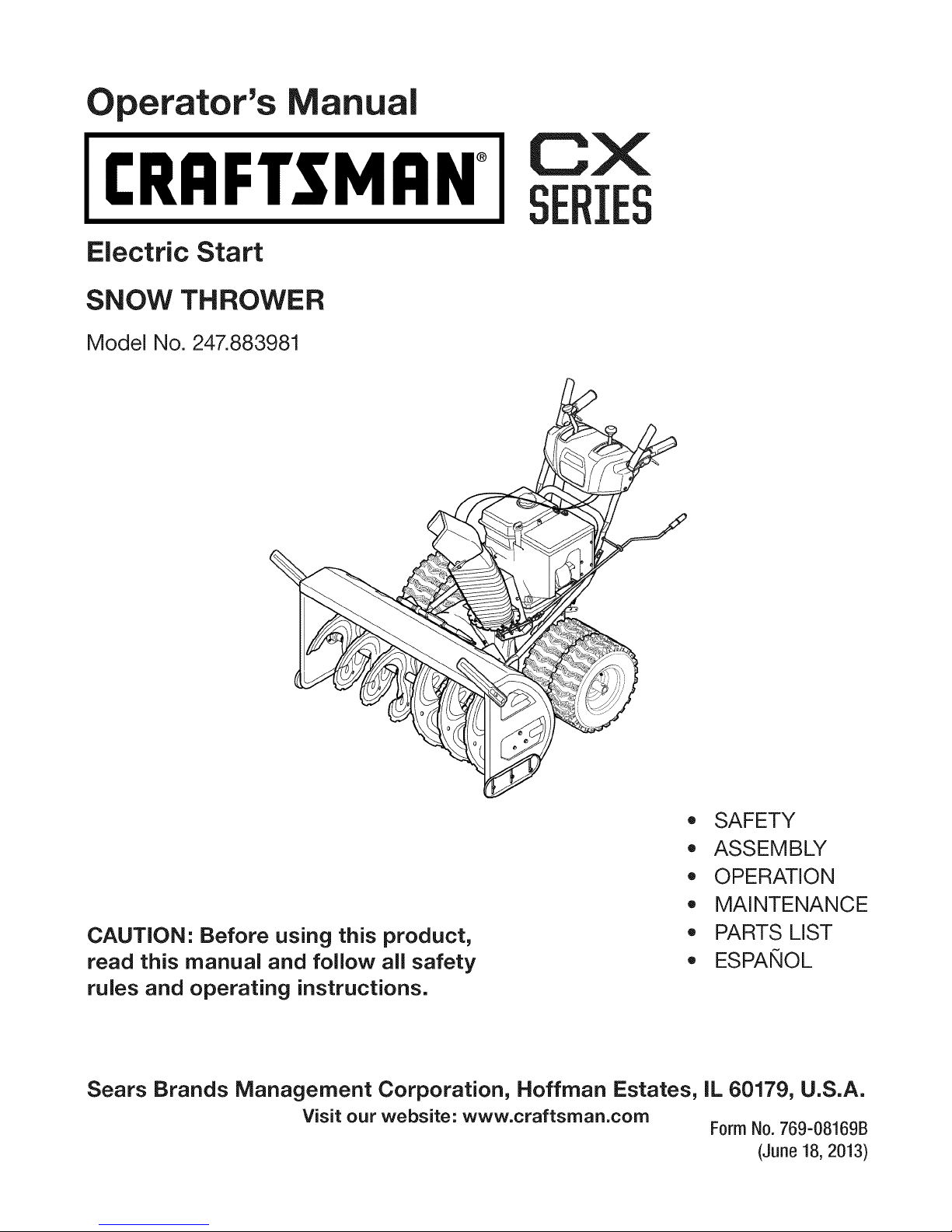
perator's nual
I:RRFrSMAN+
Electric Start
SNOW THROWER
Model No. 247.883981
CX
IES
CAUTION" Before using this product,
read this manual and follow all safety
rules and operating instructions.
Sears Brands Management Corporation, Hoffman Estates, IL 60179, U.S.A.
Visit our website: www.craftsman.com
,, SAFETY
o ASSEMBLY
OPERATION
MAINTENANCE
PARTS LIST
o ESPANOL
Form No.769-08169B
(June 18,2013)
Page 2
Warranty Statement .................................. Page 2
Safe Operation Practices .......................... Page 3
Assembly .................................................. Page 7
Operation .................................................. Page 13
Service and Maintenance ......................... Page 18
Off-Season Storage .................................. Page 26
Troubleshooting ........................................ Page 27
Parts List ................................................... Page 28
Repair Protection Agreement ................... Page 47
Espafiol ..................................................... Page 48
Service Numbers ...................................... Back Cover
CRAFTSMANCXTWOYEARFULLWARRANTY
FORTWOYEARSfromthe dateofpurchase,thisproductiswarrantedagainstanydefectsin materialorworkmanship.A defective
productwillreceivefree repairorreplacementif repairisunavailable.
Forwarranty coveragedetails to obtain free repairor replacement,visitthe website: www.craftsman.com
Thiswarranty coversONLYdefects in material andworkmanship. Warranty coveragedoes NOTinclude:
• Expendableitemsthatcanwearoutfromnormalusewithinthewarrantyperiod,includingbutnotlimitedtoaugers,augerpaddles,
driftcutters,skidshoes,shaveplate,shearpins,sparkplug,aircleaner,belts,andoil filter.
• Standardmaintenanceservicing,oilchanges,or tune-ups.
Tirereplacementorrepaircausedbypuncturesfromoutsideobjects,suchasnails,thorns,stumps,orglass.
• Tireor wheelreplacementor repairresultingfromnormalwear,accident,orimproperoperationormaintenance.
• Repairsnecessarybecauseofoperatorabuse,includingbutnotlimitedto damagecausedbyover-speedingtheengine,orfrom
impactingobjectsthatbendthe frame,augershaft,etc.
• Repairsnecessarybecauseofoperatornegligence,includingbutnotlimitedto,electricaland mechanicaldamagecausedby
improperstorage,failureto usethepropergradeandamountof engineoil,or failuretomaintaintheequipmentaccordingtothe
instructionscontainedintheoperator'smanual.
• Engine(fuelsystem)cleaningorrepairscausedbyfuel determinedtobecontaminatedor oxidized(stale).Ingeneral,fuelshouldbe
usedwithin30 daysofitspurchasedate.
• Normaldeteriorationandwearof theexteriorfinishes,orproductlabelreplacement.
Thiswarrantyisvoidif thisproductiseverusedwhileprovidingcommercialservicesor if rentedtoanotherperson.
Thiswarrantygivesyouspecificlegalrights,andyoumayalsohaveotherrightswhichvaryfromstatetostate.
SearsBrands ManagementCorporation, HoffmanEstates,IL 60179
EngineOilType: 5W-30
EngineOilCapacity: 37ounces
FuelCapacity: Approx.5 Quarts
SparkPlug: F6RTC(951-10292)
SparkPlugGap: .020"to.030"
©SearsBrands,LLC
Model Number.................................................................
Serial Number.................................................................
Dateof Purchase.............................................................
Recordthemodelnumber,serialnumber
anddateof purchaseabove
2
Page 3
Thissymbolpointsout importantsafety instructionswhich,if not
followed,couldendangerthe personalsafetyand/orproperty of
yourselfandothers.Readandfollow all instructionsinthis manual
beforeattempting to operatethis machine.Failureto complywith these
instructionsmayresultinpersonalinjury.Whenyouseethis symbol,HEED
ITSWARNING!
Thismachinewasbuilt to beoperatedaccordingtothesafeoperation
practicesinthismanual.Aswith anytype of powerequipment,
carelessnessorerroronthe part ofthe operatorcanresultinseriousinjury.
Thismachineiscapableof amputatingfingers, hands,toesandfeet and
throwingdebris.Failuretoobservethefollowing safety instructionscould
resultinseriousinjuryordeath.
CALIFORNIA PROPOSITION 65
EngineExhaust,someofits constituents,and certainvehiclecomponents
containor emit chemicalsknownto Stateof Californiatocausecancerand
birth defectsorother reproductiveharm.
TRAINING
Read,understand,andfollowall instructionsonthemachineandinthe
manual(s)beforeattemptingtoassembleandoperate.Failuretodosocan
resultinseriousinjurytotheoperatorand/orbystanders.Keepthismanual
inasafeplaceforfutureandregularreferenceandfororderingreplacement
parts.
Befamiliarwith allcontrolsandtheirproperoperation.Knowhowtostop
themachineanddisengagethemquickly.
Neverallowchildrenunder14yearsofagetooperatethismachine.Children
14andovershouldreadandunderstandtheinstructionsandsafeoperation
practicesinthis manualandonthemachineandbetrainedandsupervised
byanadult.
Neverallowadultsto operatethismachinewithout properinstruction.
Thrownobjectscancauseseriouspersonalinjury.Planyoursnow-throwing
patterntoavoiddischargeofmaterialtowardroads,bystandersandthelike.
Keepbystanders,petsandchildrenat least75feetfromthemachinewhileit
isin operation.Stopmachineif anyoneentersthearea.
Exercisecautiontoavoidslippingorfalling,especiallywhenoperatingin
reverse.
PREPARATION
Thoroughlyinspecttheareawheretheequipmentistobeused.Removeall
doormats,newspapers,sleds,boards,wiresandotherforeignobjects,which
couldbetrippedoverorthrownbytheauger/impeller.
Alwayswearsafetyglassesoreyeshieldsduringoperationandwhile
performinganadjustmentor repairto protectyoureyes.Thrownobjects
whichricochetcancauseseriousinjuryto theeyes.
Donotoperatewithout wearingadequatewinteroutergarments.Donot
wearjewelry,longscarvesorotherlooseclothing,whichcouldbecome
entangledinmovingparts.Wearfootwearwhichwill improvefootingon
slipperysurfaces.
Usea groundedthree-wireextensioncordandreceptacleforallmachines
with electricstartengines.
Your Responsibility--Restrict theuseofthis powermachineto
personswhoread,understandandfollow thewarningsandinstructionsin
thismanualandonthe machine.
SAVETHESEINSTRUCTIONS!
Disengageallcontrolleversbeforestartingtheengine.
Adjustcollectorhousingheighttocleargravelorcrushedrocksurfaces.
Neverattempttomakeanyadjustmentswhileengineisrunning,except
wherespecificallyrecommendedintheoperator'smanual.
Letengineandmachineadjusttooutdoortemperaturebeforestartingto
clearsnow.
Safe Handling of Gasoline:
Toavoidpersonalinjuryor propertydamageuseextremecareinhandling
gasoline.Gasolineisextremely flammableandthe vaporsareexplosive.
Seriouspersonalinjurycanoccurwhengasolineisspilledonyourselforyour
clotheswhichcanignite.Washyourskinandchangeclothesimmediately.
Useonlyanapprovedgasolinecontainer.
Neverfill containersinsidea vehicleoronatruckortrailerbedwitha plastic
liner.Alwaysplacecontainersonthegroundawayfromyourvehiclebefore
filling.
Whenpractical,removegas-poweredequipmentfromthetruckor
trailerandrefuelitontheground.Ifthisis notpossible,thenrefuelsuch
equipmentonatrailerwith aportablecontainer,ratherthanfromagasoline
dispensernozzle.
Keepthenozzleincontactwiththerimofthefueltankorcontaineropening
atalltimesuntilfuelingiscomplete.Donotuseanozzlelock-opendevice.
Extinguishallcigarettes,cigars,pipesandothersourcesofignition.
Neverfuelmachineindoors.
Neverremovegascaporaddfuelwhiletheengineishotorrunning.Allow
enginetocoolatleasttwominutesbeforerefueling.
Neveroverfill fueltank.Filltankto nomorethan1/2inchbelowbottomof
fillernecktoallowspaceforfuelexpansion.
Replacegasolinecapandtightensecurely.
Ifgasolineisspilled,wipeit offthe engineandequipment.Moveunitto
anotherarea.Wait.5minutesbeforestartingtheengine.
Page 4
Toreducefirehazards,keepmachinefreeofgrass,leaves,orotherdebris
build-up.Cleanupoilorfuelspillageandremoveanyfuelsoakeddebris.
Neverstorethemachineorfuelcontainerinsidewherethereisanopen
flame,sparkorpilotlightasonawaterheater,spaceheater,furnace,clothes
dryerorothergasappliances.
OPERATION
Donotputhandsorfeetnearrotatingparts,intheauger/impellerhousing
orchuteassembly.Contactwith therotatingpartscanamputatehandsand
feet.
Theauger/impellercontrolleverisasafetydevice.Neverbypassits
operation.Doingsomakesthemachineunsafeandmaycausepersonal
injury.
Thecontrolleversmustoperateeasilyin bothdirectionsandautomatically
returntothedisengagedpositionwhenreleased.
Neveroperatewith amissingordamagedchuteassembly.Keepallsafety
devicesinplaceandworking.
Neverrunanengineindoorsor inapoorlyventilatedarea.Engineexhaust
containscarbonmonoxide,anodorlessanddeadlygas.
Donotoperatemachinewhileundertheinfluenceof alcoholordrugs.
Mufflerandenginebecomehotandcancauseaburn.Donottouch.Keep
childrenaway.
Exerciseextremecautionwhenoperatingonorcrossinggravelsurfaces.Stay
alertforhiddenhazardsortraffic.
Exercisecautionwhenchangingdirectionandwhileoperatingonslopes.Do
notoperateonsteepslopes.
Planyoursnow-throwingpatterntoavoiddischargetowardswindows,
walls,carsetc.Thus,avoidingpossiblepropertydamageorpersonalinjury
causedbyaricochet.
Neverdirectdischargeatchildren,bystandersandpetsor allowanyonein
frontofthemachine.
Donotoverloadmachinecapacitybyattemptingtoclearsnowattoofastof
arate.
Neveroperatethismachinewithoutgoodvisibilityorlight.Alwaysbesureof
yourfootingandkeepafirm holdonthehandles.Walk,neverrun.
Disengagepowertotheauger/impellerwhentransportingornotinuse.
Neveroperatemachineathightransportspeedsonslipperysurfaces.Look
downandbehindandusecarewhenbackingup.
Ifthemachineshouldstartto vibrateabnormally,stoptheengine,
disconnectthesparkplugwire andgrounditagainsttheengine.Inspect
thoroughlyfordamage.Repairanydamagebeforestartingandoperating.
Disengageallcontrolleversandstopenginebeforeyouleavetheoperating
position(behindthehandles).Waituntiltheauger/impellercomesto
acompletestopbeforeuncloggingthechuteassembly,makingany
adjustments,orinspections.
Neverputyourhandin thedischargeorcollectoropenings.Donotunclog
chuteassemblywhileengineisrunning.Shutoff engineandremainbehind
handlesuntilallmovingpartshavestoppedbeforeunclogging.
Useonlyattachmentsandaccessoriesapprovedbythemanufacturer(e.g.
wheelweights,tirechains,cabsetc.).
Whenstartingengine,pull cordslowlyuntilresistanceisfelt,thenpull
rapidly.Rapidretractionofstartercord(kickback)will pullhandandarm
towardenginefasterthanyoucanletgo.Brokenbones,fractures,bruisesor
sprainscouldresult.
Ifsituationsoccurwhicharenotcoveredinthismanual,usecareandgood
judgment.
CLEARING A CLOGGED DISCHARGE CHUTE
Handcontactwiththerotatingimpellerinsidethedischargechuteisthemost
commoncauseof injuryassociatedwithsnowthrowers.Neveruseyourhandto
cleanoutthedischargechute.
Toclearthechute:
a. SHUTTHEENGINEOFF!
b. Wait10secondsto besuretheimpellerbladeshavestopped
rotating.
c. Alwaysuseaclean-outtool,notyourhands.
MAINTENANCE & STORAGE
Nevertamperwithsafetydevices.Checktheirproperoperationregularly.
Refertothemaintenanceandadjustmentsectionsofthismanual.
Beforecleaning,repairing,orinspectingmachinedisengageallcontrol
leversandstoptheengine.Waituntiltheauger/impellercometoacomplete
stop.Disconnectthesparkplugwireandgroundagainsttheengineto
preventunintendedstarting.
Checkboltsandscrewsforpropertightnessatfrequentintervalsto keepthe
machineinsafeworkingcondition.Also,visuallyinspectmachineforany
damage.
Donotchangetheenginegovernorsettingorover-speedtheengine.The
governorcontrolsthemaximumsafeoperatingspeedoftheengine.
Snowthrowershaveplatesandskidshoesaresubjecttowearanddamage.
Foryoursafetyprotection,frequentlycheckallcomponentsandreplace
with originalequipmentmanufacturer's(OEM)partsonlyaslistedinthe
Partspagesofthisoperator'smanual.Useof partswhichdonot meetthe
originalequipmentspecificationsmayleadtoimproperperformanceand
compromisesafety!
Checkcontrolleversperiodicallytoverifytheyengageanddisengage
properlyandadjust,ifnecessary.Refertotheadjustmentsectioninthis
operator'smanualfor instructions.
Maintainorreplacesafetyandinstructionlabels,asnecessary.
Observeproperdisposallawsandregulationsforgas,oil,etc.toprotectthe
environment.
Priortostoring,runmachineafewminutestoclearsnowfrommachineand
preventfreezeupofauger/impeller.
Neverstorethemachineorfuelcontainerinsidewherethereisanopen
flame,sparkorpilotlight suchasa waterheater,furnace,clothesdryeretc.
Alwaysrefertotheoperator'smanualforproperinstructionsonoff-season
storage.
4
Page 5
Checkfuelline,tank,cap,andfittingsfrequentlyforcracksor leaks.Replace
if necessary.
Donotcrankenginewith sparkplugremoved.
AccordingtotheConsumerProductsSafetyCommission(CPSC)andthe
U.S.EnvironmentalProtectionAgency(EPA),thisproducthasanAverage
Useful Lifeofseven(7)years,or60hoursofoperation.Attheendof
theAverage Useful Lifehavethemachineinspectedannuallybyan
authorizedservicedealertoensurethatallmechanicalandsafetysystems
areworkingproperlyandnotwornexcessively.Failureto dosocanresultin
accidents,injuriesordeath.
DO NOT MODIFY ENGINE
Toavoidseriousinjuryordeath,donotmodifyengineinanyway.Tampering
with the governorsetting canleadto arunawayengineandcauseit to
operateat unsafespeeds.Nevertamperwith factorysetting ofengine
governor.
NOTICE REGARDING EMiSSiONS
Engineswhichare certifiedto complywith CaliforniaandfederalEPA
emissionregulationsfor SORE(SmallOffRoadEquipment)arecertified
tooperateonregularunleadedgasoline,and mayincludethe following
emissioncontrolsystems:EngineModification (EM),OxidizingCatalyst(0C),
SecondaryAir injection(SAI)andThreeWayCatalyst(TWC)if soequipped.
SPARK ARRESTOR
e
Thismachineisequippedwith aninternalcombustionengineandshould
not beusedonornearanyunimprovedforest-covered,brushcoveredor
grass-coveredland unlessthe engine'sexhaustsystemisequippedwith a
sparkarrestormeetingapplicablelocalorstatelaws(if any).
Ira sparkarrestorisused,it shouldbemaintainedin effectiveworking order
bythe operator.IntheState ofCaliforniathe aboveisrequired bylaw (Section
4442ofthe CaliforniaPublicResourcesCode).Otherstates mayhavesimilar
laws.Federallawsapplyonfederal lands.
Asparkarrestorfor the muffler isavailablethroughyournearestSearsParts
andRepairServiceCenter.
Page 6
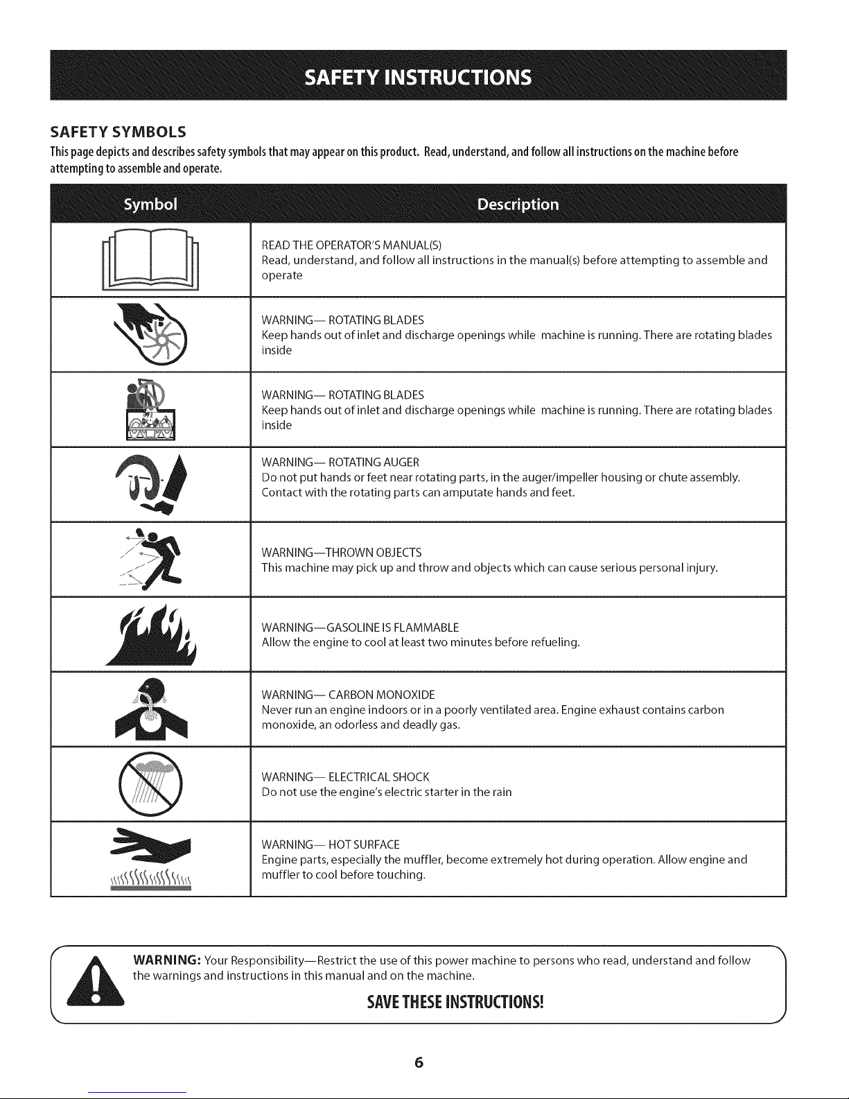
SAFETY SYMBOLS
Thispage depicts and describes safety symbols that may appear on this product. Read,understand, and follow all instructions on the machine before
attempting to assemble and operate.
READ THE OPERATOR'S MANUAL(S)
Read, understand, and follow all instructions in the manual(s) before attempting to assemble and
operate
WARNING-- ROTATING BLADES
Keep hands out of inlet and discharge openings while machine is running. There are rotating blades
inside
WARNING-- ROTATING BLADES
Keep hands out of inlet and discharge openings while machine is running. There are rotating blades
inside
WARNING-- ROTATING AUGER
Do not put hands or feet near rotating parts, in the auger/impeller housing or chute assembly.
Contact with the rotating parts can amputate hands and feet.
WARNING--THROWN OBJECTS
This machine may pick up and throw and objects which can cause serious personal injury.
WARNING--GASOLINE IS FLAMMABLE
Allow the engine to cool at least two minutes before refueling.
WARNING-- CARBON MONOXIDE
Never run an engine indoors or in a poorly ventilated area. Engine exhaust contains carbon
monoxide, an odorless and deadly gas.
WARNING-- ELECTRICAL SHOCK
Do not use the engine's electric starter in the rain
WARNING-- HOT SURFACE
Engine parts, especially the muffler, become extremely hot during operation. Allow engine and
muffler to cool before touching.
WARNING: Your Responsibility--Restrict the use of this power machine to persons who read, understand and follow
the warnings and instructions in this manual and on the machine.
SAVETHESEiNSTRUCTIONS!
6
Page 7
NOTE:Referencesto rightor leftsideofthesnowthroweraredeterminedfromthe
operatingpositionlookingforwardto thefrontofthemachine.
RemovingFrom(:rate
1. Removescrewsfromthebottomofthecratesecuringthesides,andendsof
theshippingcrate.
2. Lift offthetopoffof thecrateandsetoutofthewayoftheassemblyarea.
3. Removeanddiscardplasticbagthatcoversunit.
4. Removeanyloosepartsincludedwith unit(e.g.,Operator'sManual,etc.).
5. Pushdownonthelowerhandleandpull unitbackoutofcrate.
6. Makecertainthecratehasbeencompletelyemptiedbeforediscardingit.
Assembly
Makecertainthespringsatthelowerendoftheaugeranddrive
cablesaresecurelyhookedintotheir respectiveactuator
bracketsbeforepivotingthehandleupward.Referto Figure14.
a.
PlacethespeedselectorshiftleverintheF6position.
b.
Cutthecabletiesecuringthetwo piecechutecranktothe
lowerhandle.Thecabletie isusedforshippingpurposes.
Removetheupperwingknobandcarriageboltfromeach
sideofthe lowerhandle.Pulluponupperhandleasshown
in Figure1.Alignupperhandlewiththelowerhandle.Again,
makecertainthespringsatthelowerendoftheaugerand
drivecablesaresecurelyhookedintotheirrespective
actuatorbrackets.Also,removeanyrubberbandssecuring
thecablesto thewingnuts.
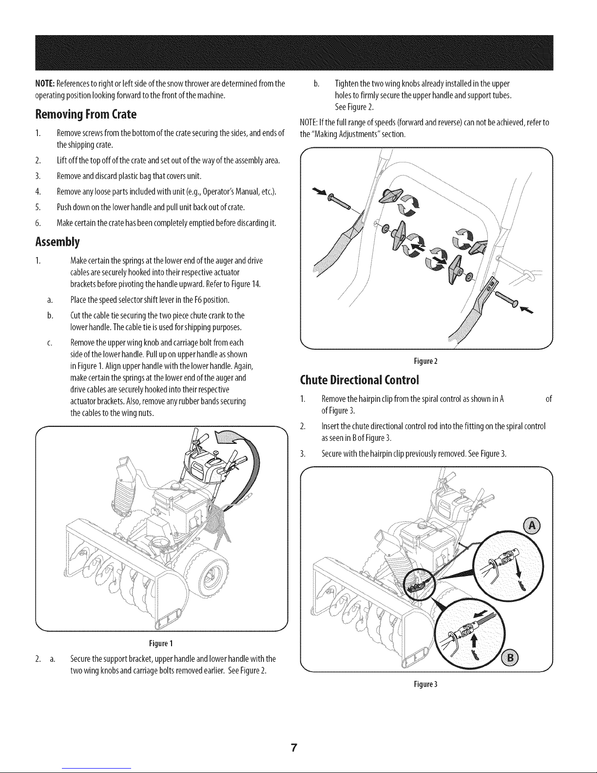
b. Tightenthetwowingknobsalreadyinstalledintheupper
holesto firmly securetheupperhandleandsupporttubes.
SeeFigure2.
NOTE:Ifthefull rangeof speeds(forwardandreverse)cannotbeachieved,referto
the"MakingAdjustments"section.
!
RemovethehairpinclipfromthespiralcontrolasshowninA of
ofFigure3.
Insertthechutedirectionalcontrolrodintothefitting onthespiralcontrol
asseeninBofFigure3.
3.
Securewiththehairpinclippreviouslyremoved.SeeFigure3.
F"
Figure1
2. a. Securethesupportbracket,upperhandleandlowerhandlewith the
twowingknobsandcarriageboltsremovedearlier.SeeFigure2.
Figure3
7
Page 8
ChuteAssembly
Set-Lip
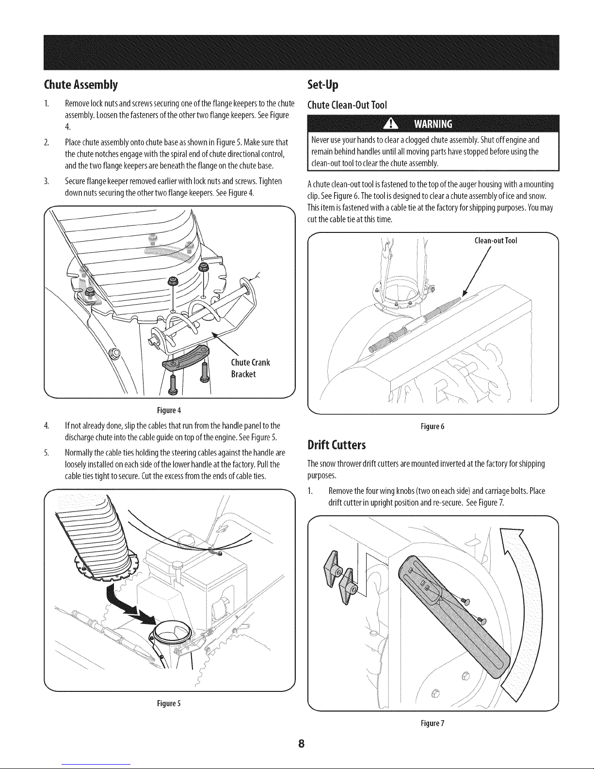
Removelocknutsandscrewssecuringoneoftheflangekeepersto thechute
assembly.Loosenthefastenersof theothertwoflangekeepers.SeeFigure
4.
2. Placechuteassemblyontochutebaseasshownin Figure5.Makesurethat
thechutenotchesengagewith thespiralendofchutedirectionalcontrol,
andthetwo flangekeepersarebeneaththeflangeonthechutebase.
3. Secureflangekeeperremovedearlierwith locknutsandscrews.Tighten
downnutssecuringtheothertwoflangekeepers.SeeFigure4.
ChuteClean-OutTool
Neveruseyourhandstoclearacloggedchuteassembly.Shutoffengine and
remainbehindhandlesuntilall movingpartshavestoppedbeforeusingthe
clean-outtooltoclearthechuteassembly.
Achuteclean-outtool isfastenedtothetopoftheaugerhousingwithamounting
clip.SeeFigure6.Thetoolis designedtoclearachuteassemblyof iceandsnow.
Thisitemisfastenedwithacabletieat thefactoryforshippingpurposes.Youmay
cutthecabletieat thistime.
Clean-outTool
!,//
Figure4
4. If notalreadydone,slipthecablesthatrunfromthe handlepanelto the
dischargechuteintothecableguideontopoftheengine.SeeFigure5.
5. Normallythecabletiesholdingthesteeringcablesagainstthehandleare
looselyinstalledoneachsideofthelowerhandleatthefactory.Pullthe
cabletiestight tosecure.Cuttheexcessfromtheendsofcableties.
\
/
i/
Figure6
Drift Cutters
Thesnowthrowerdrift cuttersaremountedinvertedatthefactoryforshipping
purposes.
1. Removethefourwingknobs(twooneachside)andcarriagebolts.Place
drift cutterinuprightpositionandre-secure.SeeFigure7.
i i
J
Figure5
J
Figure7
8
Page 9
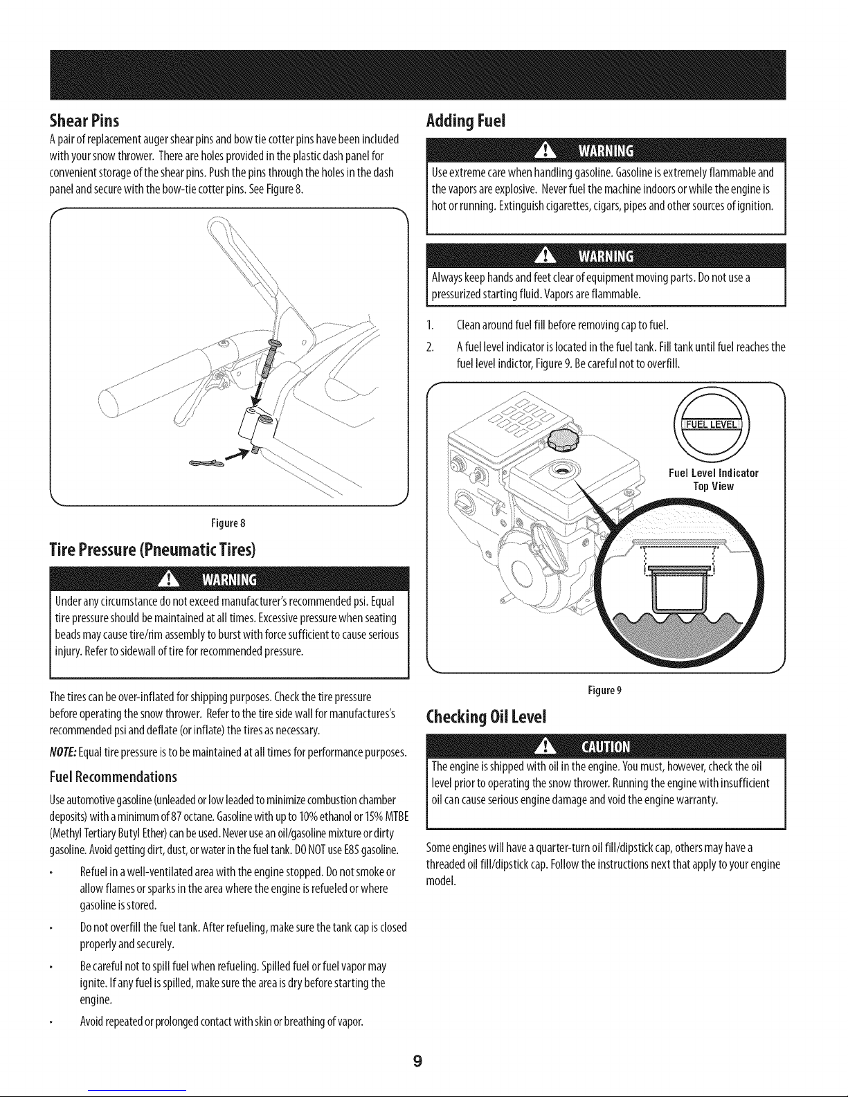
ShearPins
Apairofreplacementaugershearpinsandbowtiecotterpinshavebeenincluded
with yoursnowthrower.Thereareholesprovidedintheplasticdashpanelfor
convenientstorageoftheshearpins.Pushthepinsthroughtheholesinthedash
panelandsecurewith thebow-tiecotterpins.SeeFigure8.
AddingFuel
Useextremecarewhenhandlinggasoline.Gasolineisextremelyflammableand
thevaporsareexplosive.Neverfuel themachineindoorsorwhiletheengineis
hotorrunning.Extinguishcigarettes,cigars,pipesandothersourcesof ignition.
Alwayskeephandsandfeetclearofequipmentmovingparts.Donotusea
pressurizedstartingfluid.Vaporsareflammable.
1. Cleanaroundfuelfill beforeremovingcaptofuel.
2. Afuellevelindicatorislocatedinthefueltank.Filltankuntilfuelreachesthe
fuellevelindictor,Figure9. Becarefulnottooverfill.
@
FnelLevelIndicator
TopView
Figure8
TirePressure(PneumaticTires)
Underanycircumstancedonotexceedmanufacturer'srecommendedpsi.Equal
tire pressureshouldbemaintainedatalltimes.Excessivepressurewhenseating
beadsmaycausetire/rimassemblyto burstwith forcesufficienttocauseserious
injury.Refertosidewalloftire forrecommendedpressure.
Thetirescanbeover-inflatedforshippingpurposes.Checkthetirepressure
beforeoperatingthesnowthrower.Refertothetiresidewallfor manufactures's
recommendedpsianddeflate(orinflate)thetiresasnecessary.
NOTE:Equaltirepressureistobemaintainedatalltimesfor performancepurposes.
FuelRecommendations
Useautomotivegasoline(unleadedorlowleadedto minimizecombustionchamber
deposits)with aminimumof87octane.Gasolinewith upto10%ethanolor15%MTBE
(MethylTertiaryButylEther)canbeused.Neveruseanoil/gasolinemixtureordirty
gasoline.Avoidgettingdirt,dust,orwaterinthefueltank.DONOTuseE85gasoline.
Refuelinawell-ventilatedareawiththeenginestopped.Donotsmokeor
allowflamesorsparksintheareawheretheengineisrefueledorwhere
gasolineisstored.
Donotoverfillthefueltank.Afterrefueling,makesurethetankcapisclosed
properlyandsecurely.
Becarefulnottospillfuel whenrefueling.Spilledfuelorfuelvapormay
ignite.Ifanyfuelisspilled,makesuretheareaisdrybeforestartingthe
engine.
Avoidrepeatedorprolongedcontactwith skinorbreathingofvapor.
Figure9
CheckingOilLevel
Theengineisshippedwithoilintheengine.Youmust,however,checktheoil
levelpriortooperatingthesnowthrower.Runningtheenginewith insufficient
oilcancauseseriousenginedamageandvoidtheenginewarranty.
Someengineswill haveaquarter-turnoilfill/dipstickcap,othersmayhavea
threadedoilfill/dipstickcap.Followtheinstructionsnextthatapplyto yourengine
model.
9
Page 10
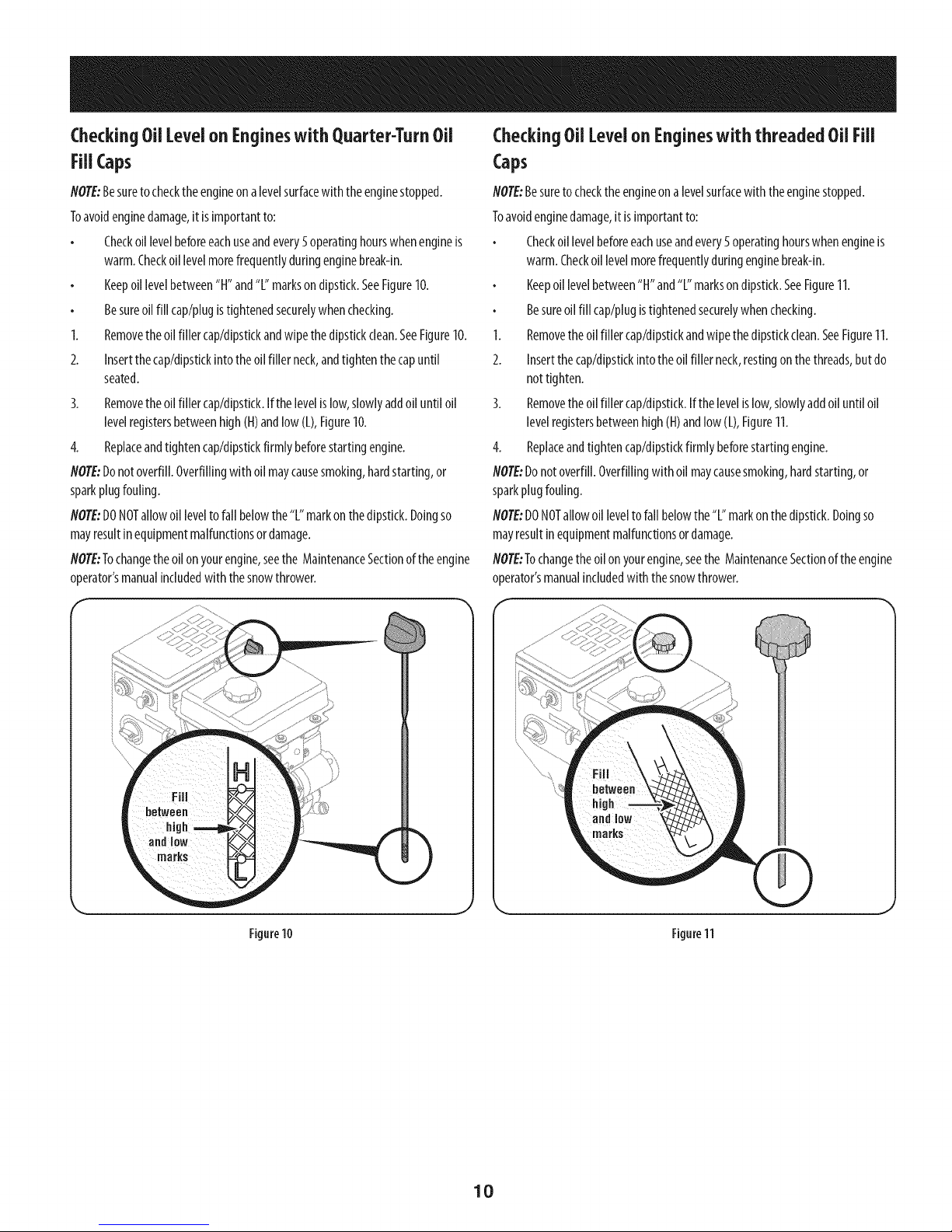
CheckingOilLevelon Engineswith Quarter-TurnOil
Fill Caps
CheckingOilLevelonEngineswith threaded OilFill
Caps
NOTE:Besuretocheckthe engineonalevelsurfacewith theenginestopped.
Toavoidenginedamage,it isimportantto:
Checkoillevelbeforeeachuseandevery5operatinghourswhenengineis
warm.Checkoil levelmorefrequentlyduringenginebreak-in.
Keepoillevelbetween"H" and"L"marksondipstick.SeeFigure10.
Besureoilfill cap/plugistightenedsecurelywhenchecking.
1. Removetheoilfillercap/dipstkkandwipethedipstickclean.SeeFigure10.
2. Insertthecap/dipstkkintotheoilfillerneck,andtightenthecapuntil
seated.
3. Removetheoilfillercap/dipstkk.Ifthelevelislow,slowlyaddoil untiloil
levelregistersbetweenhigh(H)andlow(L),Figure10.
4. Replaceandtightencap/dipstkkfirmlybeforestartingengine.
NOTE:Donotoverfill.Overfillingwith oilmaycausesmoking,hardstarting,or
sparkplugfouling.
NOTE:DONOTallowoilleveltofall belowthe"L" markonthedipstick.Doingso
mayresultinequipmentmalfunctionsordamage.
NOTE:Tochangetheoilonyourengine,seetheMaintenanceSectionoftheengine
operator'smanualincludedwith thesnowthrower.
NOTE:Besureto checktheengineonalevelsurfacewith theenginestopped.
Toavoidenginedamage,it isimportantto:
Checkoillevelbeforeeachuseandevery5 operatinghourswhenengineis
warm.Checkoillevelmorefrequentlyduringenginebreak-in.
Keepoil levelbetween"H"and"L"marksondipstick.SeeFigure11.
Besureoil fill cap/plugistightenedsecurelywhenchecking.
1. Removetheoilfillercap/dipstkkandwipethedipstickclean.SeeFigure11.
2. Insertthecap/dipstkkintotheoil fillerneck,restingonthethreads,butdo
nottighten.
3. Removetheoilfillercap/dipstick.If thelevelislow,slowlyaddoiluntiloil
levelregistersbetweenhigh(H)andlow(L),Figure11.
4. Replaceandtightencap/dipstickfirmly beforestartingengine.
NOTE:Donotoverfill.Overfillingwithoil maycausesmoking,hardstarting,or
sparkplugfouling.
NOTE:DONOTallowoil leveltofallbelowthe"L"markonthedipstick.Doingso
mayresultinequipmentmalfunctionsordamage.
NOTE:Tochangetheoilonyourengine,seethe MaintenanceSectionoftheengine
operator'smanualincludedwith thesnowthrower.
Figure10
Figure11
10
Page 11

Adjustments Auger and Drive Control Cables
SkidShoes
Priortooperatingyoursnowthrower,carefullyreadandfollowallinstructions
Itis notrecommendedthatyouoperatethissnowthrowerongravelasitcan
easilypickupandthrowloosegravel,causingpersonalinjuryordamagetothe
snowthrowerandsurroundingproperty.
Thesnowthrowerskidshoesareadjustedupwardat thefactoryfor shipping
purposes.Adjustthemdownwardpriortooperatingthemachine.
Forclosesnowremovalonasmoothsurface,adjusttheskidshoessothattheshave
plateonthebottomofthe augerhousingisjustoffthe ground.
Adjusttheskidshoesto alowerpositiontoraisetheshaveplateoffthe ground
whenclearingunevenareas,suchasa ribbontypedrivewayoragraveldriveway
NOTE:Ifyouchoosetooperatethesnowthroweronagravelsurface,keeptheskid
shoesin positionfor maximumclearancebetweenthegroundandtheshaveplate.
Toadjust the skidshoes:
1. Adjustskidshoesbylooseningthesix(threeoneachside)hexnutsand
carriageboltssecuringtheskidshoestotheaugerhousing.RefertoFigure
12.
below.Performalladjustmentsto verifyyoursnowthrowerisoperatingsafely
andproperly.
TestingAugerDriveControl
Whentheaugercontrolisreleasedandinthedisengaged"up"position,thecable
shouldhaveverylittleslack,butshouldNOTbetight. Referto Figure13forlocation
ofcontrols.
F
ChuteTiltControl_ _ Shift Lever
Auge, n. ,, ve
Auger d___ Drive
2_
H- ---coot,u,
Lower
Shave
ShavePlate
. Plate j
Figure12
2. Whileobservingthe distancebetweentheshaveplateandtheground,
adjusttheskidsshoesupordowntoachievethedesiredshaveplateheight.
SeeFigure12.
3. Makecertaintheentirebottomsurfaceofskidshoesareagainsttheground
toavoidunevenwearontheskidshoes;thentightennutsandboltssecurely.
Plate
Raise
Shave
J
Figure13
1. Inawell-ventilatedarea,startthesnowthrowerengineasinstructedinthe
Operationsection.
2. Whilestandingintheoperator'sposition(behindthesnowthrower),engage
theaugercontrolandallowtheaugertoremainengagedfor approximately
tensecondsbeforereleasingtheaugercontrol.Repeatthisseveraltimes.
NOTE: Whenengagingtheauger,youmayheara"chirp"sound.Thisisnormal,it
isthebeltengagingthepulley.Asthebeltwears,thissoundwill notbeheardwhen
engagingtheauger.
3. Withtheenginerunningandtheaugercontrolin thedisengaged"up"
position,walktothefrontofthemachine.Confirmthatthe augerhas
completelystoppedrotatingandshowsnosignsofmotion.
4. Iftheaugershowsanysignsofrotating,immediatelyreturntotheoperator's
positionandshutoff theengine.Waitfor allmovingpartstostopbefore
readjustingtheaugercontrolcable.
11
Page 12
TestingWhee{ Dr}reContro{& SpeedSelectorLever
RefertoFigure13for{ocationofcontro{s.
I. Movethespeedselectorshift{everintosixth(6)posit{on.
2. Withthewheeldrivecontro{released,pushthesnowthrowerforward,thenpull
itback.Themachineshouldmovefreely.
3. Engagethedrivecontrolandattempttomovethemachinebothforwardand
back,resistanceshouldbefelt.
4. Movethespeedselectorshiftleverintothefastreverse(R2)positionandrepeat
theprevioustwosteps.
Ifyouexperiencedresistancerollingtheunit,eitherwhenrepos{tioningthespeed
selectorshiftleverfrom6 toR2orwhenattemptingtomovethemachinewiththedrive
controlreleased,adjustthedrivecontrolimmediately.SeeAdjustingDriveandAuger
Controls.
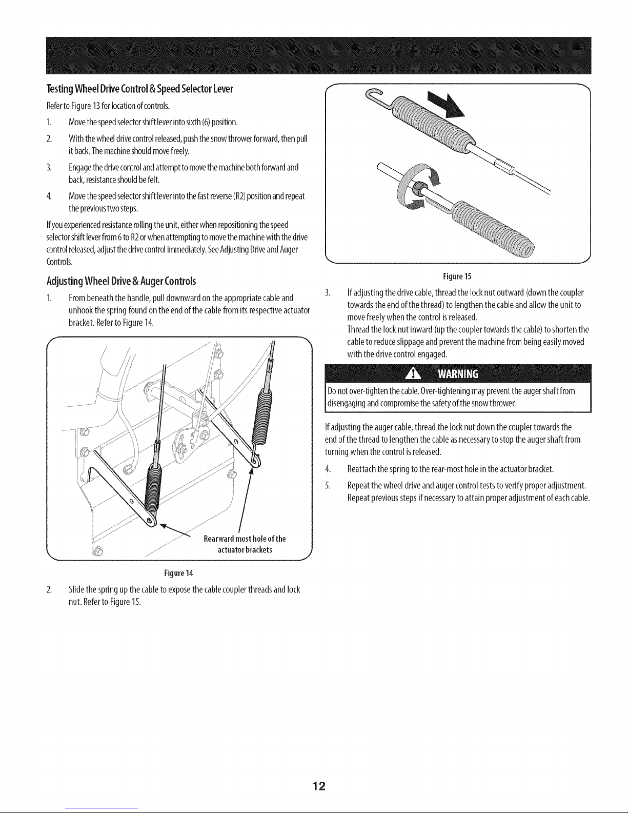
AdjustingWhee{Dr}re&Auger(ontro{s
1. Frombeneaththehandle,pulldownwardontheappropriatecableand
unhookthespringfoundontheendofthecablefromitsrespectiveactuator
bracket.RefertoFigure14.
J
Figure15
Ifadjustingthedrivecable,threadthelocknutoutward(downthecoupler
towardstheendofthethread)to lengthenthecableandallowtheun{tto
movefreelywhenthecontrol{sreleased.
Threadthelocknut inward(upthecouplertowardsthecable)toshortenthe
cableto reduceslippageandpreventthemach{nefrombeingeas{lymoved
w{ththedr{vecontrolengaged.
Rearwardmostholeofthe
...... actuatorbrackets
Figure14
2. S{{dethespringupthecab{eto exposethecab{ecoup{erthreadsand{ock
nut.RefertoFigure15.
Donotover-tightenthecable.Over-tighteningmaypreventtheaugershaftfrom
disengagingandcompromisethesafetyofthesnowthrower.
Ifadjustingtheaugercable,threadthelocknutdownthecouplertowardsthe
endofthethreadtolengthenthecableasnecessarytostoptheaugershaftfrom
turningwhenthecontrolisreleased.
4. Reattachthespringtotherear-mostholeintheactuatorbracket.
5. Repeatthewheeldriveandaugercontrolteststo verifyproperadjustment.
Repeatpreviousstepsifnecessaryto attainproperadjustmentofeachcable.
12
Page 13
f SpeedSelector "
Drive ChuteControF M
AugerControl
Headlight
ChuteAssembly
DriftCutters
WheelSteeringControl
Chute
Clean-outTool
\
Augers
.%o,
SkidShoes
Figure
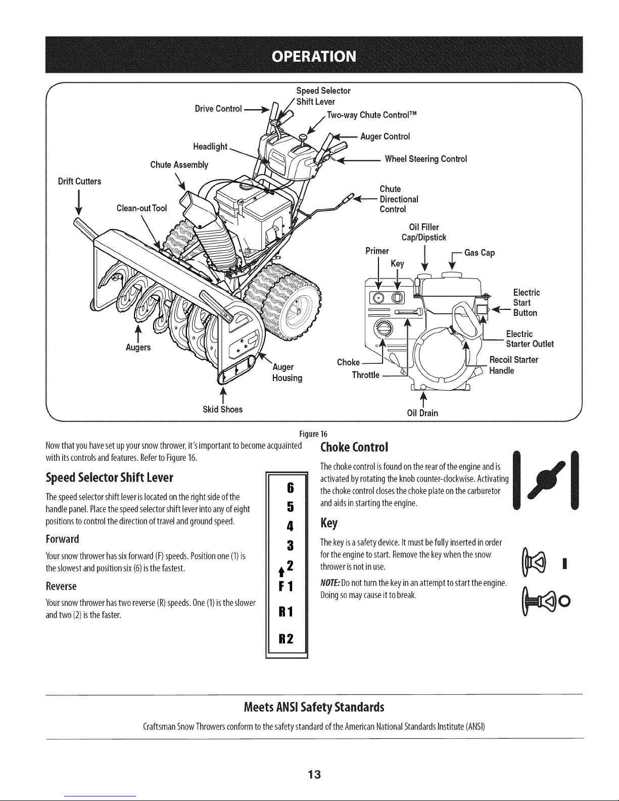
Nowthatyouhavesetupyoursnowthrower,it'simportanttobecomeacquainted
with itscontrolsandfeatures.Referto Figure16.
SpeedSelectorShift Lever
Thespeedselectorshiftleverislocatedontherightsideofthe
handlepanel.Placethespeedselectorshift leverintoanyof eight
positionstocontrolthedirectionoftravelandgroundspeed.
Forward
Yoursnowthrowerhassixforward(F)speeds.Positionone(1)is
theslowestandpositionsix(6)isthefastest.
Reverse
Yoursnowthrowerhastworeverse(R)speeds.One(1)istheslower
andtwo(2)isthefaster.
6
5
4
3
t 2
F1
R1
Control
Oil Filler
Cap/Dipstick
PrimerKey
Recoil Starter
Ch°kTh
Oil Drain
16
Handle
ChokeControl
Thechokecontrolisfoundontherearoftheengineandis
activatedbyrotatingtheknobcounter-clockwise.Activating
thechokecontrolclosesthechokeplateonthecarburetor
andaidsinstartingtheengine.
Key
Thekeyisasafetydevice.Itmustbefully insertedinorder
fortheenginetostart.Removethekeywhenthesnow
throwerisnotin use.
NOTE:Donotturnthekeyinanattempttostarttheengine.
Doingsomaycauseittobreak.
Electric
Start
Button
Electric
Outlet
CraftsmanSnowThrowersconformtothesafetystandardof theAmericanNationalStandardsInstitute(ANSI)
R2
MeetsANSISafety Standards
13
Page 14
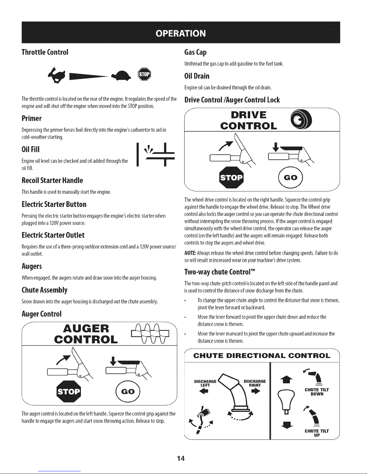
ThrottleControl
GasCap
Unthreadthegascaptoaddgasolineto thefueltank.
==-,.-
Thethrottlecontrolislocatedontherearoftheengine.Itregulatesthespeedofthe
engineandwillshutoffthe enginewhenmovedintotheSTOPposition.
Primer
Depressingtheprimerforcesfueldirectlyintotheengine'scarburetorto aidin
cold-weatherstarting.
0UFili [ _,,_.J__,.
Engineoillevelcanbecheckedandoiladdedthroughthe
oilfill.
RecoilStarter Handle
Thishandleisusedto manuallystarttheengine.
ElectricStarterButton
Pressingtheelectricstarterbuttonengagestheengine'selectricstarterwhen
pluggedintoa 120Vpowersource.
ElectricStarterOutlet
Requirestheuseofathree-prongoutdoorextensioncordanda120Vpowersource/
walloutlet.
Augers
Whenengaged,theaugersrotateanddrawsnowintotheaugerhousing.
ChuteAssembly
Snowdrawnintotheaugerhousingisdischargedoutthechuteassembly.
AugerControl
f AUGER
CONTROL
OUDrain
Engineoilcanbedrainedthroughtheoildrain.
DriveControl/Auger Control Lock
/ DRIVE
CONTROL
J
Thewheeldrivecontrolislocatedontherighthandle.Squeezethecontrolgrip
againstthehandletoengagethewheeldrive.Releasetostop.TheWheeldrive
controlalsolockstheaugercontrolsoyoucanoperatethechutedirectionalcontrol
withoutinterruptingthesnowthrowingprocess.Iftheaugercontrolisengaged
simultaneouslywith thewheeldrivecontrol,theoperatorcanreleasetheauger
control(onthelefthandle)andtheaugerswill remainengaged.Releaseboth
controlsto stoptheaugersandwheeldrive.
NOTE:Alwaysreleasethewheeldrivecontrolbeforechangingspeeds.Failuretodo
sowill resultinincreasedwearonyourmachine'sdrivesystem.
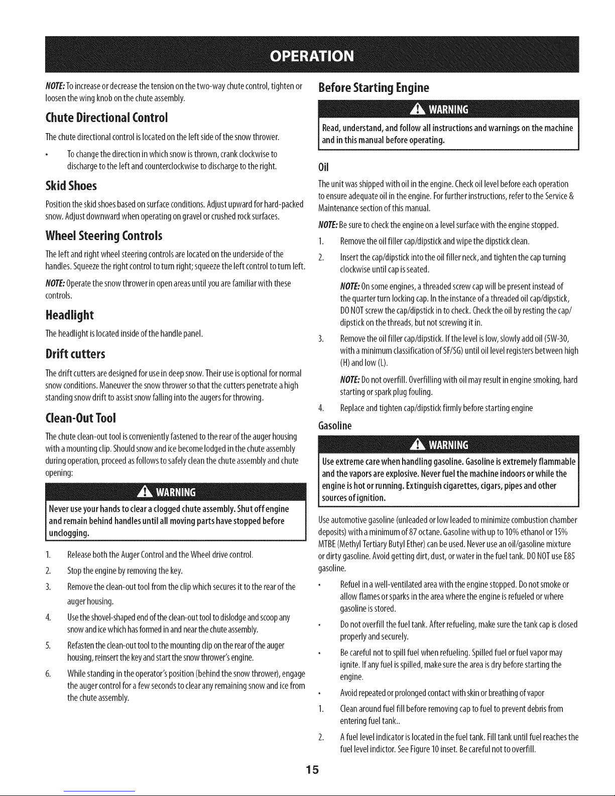
Two-waychute Control"
Thetwo-waychute-pitchcontrolislocatedon theleft sideofthehandlepaneland
isusedto controlthedistanceofsnowdischargefromthechute.
Tochangetheupperchuteangletocontrolthedistancethat snowisthrown,
pivottheleverforwardorbackward.
Movetheleverforwardtopivottheupperchutedownandreducethe
distancesnowisthrown.
Movetheleverrearwardtopivottheupperchuteupwardandincreasethe
distancesnowisthrown.
Theaugercontrolislocatedonthelefthandle.Squeezethecontrolgripagainstthe
handletoengagetheaugersandstartsnowthrowingaction.Releasetostop.
S
CHUTE DIRECTIONAL CONTROL
DISCHARGE
LEFT
J
1;DISDHARDE
i
CHUTE TILT
DOWN
CHUTE TILT
UP
J
14
Page 15
NOTE:Toincreaseordecreasethetensiononthetwo-waychutecontrol,tightenor
loosenthewingknobonthechuteassembly.
ChuteDirectional Control
Thechutedirectionalcontrolislocatedontheleftsideofthesnowthrower.
Tochangethedirectioninwhichsnowisthrown,crankclockwiseto
dischargetotheleftandcounterclockwisetodischargetotheright.
BeforeStartingEngine
Read,understand,andfollow all instructionsandwarningsonthemachine
andinthis manualbeforeoperating.
Oil
SkidShoes
Positiontheskidshoesbasedonsurfaceconditions.Adjustupwardforhard-packed
snow.Adjustdownwardwhenoperatingongravelorcrushedrocksurfaces.
WheelSteeringControls
Theleftandrightwheelsteeringcontrolsarelocatedontheundersideofthe
handles.Squeezetheright controlto turnright;squeezetheleft controltoturnleft.
NOTE:Operatethesnowthrowerinopenareasuntilyouarefamiliarwiththese
controls.
Headlight
Theheadlightis locatedinsideofthe handlepanel.
Drift cutters
Thedrift cuttersaredesignedforusein deepsnow.Theiruseisoptionalfornormal
snowconditions.Maneuverthesnowthrowersothatthecutterspenetratea high
standingsnowdriftto assistsnowfallingintotheaugersforthrowing.
Clean-OutTool
Thechuteclean-outtoolisconvenientlyfastenedtotherearoftheaugerhousing
with amountingclip.Shouldsnowandicebecomelodgedinthechuteassembly
duringoperation,proceedasfollowstosafelycleanthechuteassemblyandchute
opening:
Neveruseyour handstoclearacloggedchuteassembly.Shutoffengine
andremain behindhandlesuntil all movingpartshavestoppedbefore
unclogging.
1. ReleaseboththeAugerControlandtheWheeldrivecontrol.
2. Stoptheenginebyremovingthekey.
3. Removetheclean-outtoolfromtheclipwhichsecuresit totherearofthe
augerhousing.
4. Usetheshovel-shapedendoftheclean-outtooltodislodgeandscoopany
snowandicewhichhasformedinandnearthechuteassembly.
5. Refastentheclean-outtooltothemountingclipontherearof theauger
housing,reinsertthekeyandstartthesnowthrower'sengine.
6. Whilestandingintheoperator'sposition(behindthesnowthrower),engage
theaugercontrolfor afewsecondsto clearanyremainingsnowandicefrom
thechuteassembly.
Theunitwasshippedwithoilin theengine.Checkoil levelbeforeeachoperation
toensureadequateoil intheengine.Forfurtherinstructions,refertotheService&
Maintenancesectionofthismanual.
NOTE:Besureto checktheengineonalevelsurfacewith theenginestopped.
1. Removetheoilfillercap/dipstickandwipethedipstickclean.
2. Insertthecap/dipstickintotheoil fillerneck,andtightenthecapturning
clockwiseuntil capisseated.
flOTE:Onsomeengines,athreadedscrewcapwill bepresentinsteadof
thequarterturnlockingcap.Intheinstanceof athreadedoilcap/dipstick,
DONOTscrewthecap/dipstickin tocheck.Checktheoilbyrestingthecap/
dipstickonthethreads,butnotscrewingit in.
Removetheoilfillercap/dipstick.Ifthelevelislow,slowlyaddoil(5W-30,
with aminimumclassificationofSF/SG)untiloil levelregistersbetweenhigh
(H)andlow(L).
flOTE:Donotoverfill.Overfillingwithoil mayresultinenginesmoking,hard
startingorsparkplugfouling.
Replaceandtightencap/dipstickfirmly beforestartingengine
Gasoline
Useextremecarewhen handlinggasoline.Gasolineisextremelyflammable
andthe vaporsare explosive.Neverfuel the machineindoorsorwhile the
engineishot orrunning. Extinguishcigarettes,cigars,pipesandother
sourcesof ignition.
Useautomotivegasoline(unleadedorlowleadedtominimizecombustionchamber
deposits)with aminimumof87octane.Gasolinewith upto 10%ethanolor 15%
MTBE(MethylTertiaryButylEther)canbeused.Neveruseanoil/gasolinemixture
ordirty gasoline.Avoidgettingdirt,dust,orwaterinthefueltank.DONOTuseE85
gasoline.
Refuelinawell-ventilatedareawith theenginestopped.Donotsmokeor
allowflamesorsparksintheareawheretheengineisrefueledorwhere
gasolineisstored.
Donotoverfillthefueltank.Afterrefueling,makesurethetankcapisclosed
properlyandsecurely.
Becarefulnottospillfuel whenrefueling.Spilledfuelorfuelvapormay
ignite.If anyfuelisspilled,makesuretheareaisdrybeforestartingthe
engine.
Avoidrepeatedorprolongedcontactwith skinorbreathingofvapor
1. Cleanaroundfuelfill beforeremovingcaptofuelto preventdebrisfrom
enteringfueltank..
2. Afuellevelindicatorislocatedinthefueltank.Filltankuntil fuelreachesthe
fuellevelindictor.SeeFigure10inset.Becarefulnottooverfill.
15
Page 16

Starting The Engine
Alwayskeephandsandfeet dear of movingparts.Donotusea pressurized
starting fluid. Vaporsareflammable.
NOTE:Allowtheengineto warmupforafew minutesafterstarting.The
enginewill notdevelopfull poweruntilit reachesoperatingtemperatures.
Makecertainboththeaugercontrolandwheeldrivecontrolareinthe
disengaged(released)position.
Insertkeyintoslot.Makesureit snapsintoplace.Donotattemptto turnthe
key.
NOTE:Theenginecannotstartwithoutthekeyfullyinsertedintothe
ignitionswitch.
Eiectrk Starter
Theoptional e[ectrk starter isequippedwith agroundedpowerplug, and
isdesignedto operateonanextensioncordratedfor 15ampsat 125volts,
groundedandratedfor outdooruseusing120volt AChouseholdcurrent,it
mustbe usedwith aproperlygroundedthree-prongreceptacleatai[times
toavoidthe possibilityofeiectrk shock.Followall instructionscarefully
priorto operating theelectricstarter.
Determinethatyourhome'swiringisathree-wiregroundedsystem.Askalicensed
electricianifyouarenotcertain.
Ifyouhaveagroundedthree-prongreceptacle,proceedasfollows:
1. Pluganextensioncordintotheoutlet locatedontheengine'ssurface.Plug
theotherendofextensioncordintoathree-prong120-volt,grounded,AC
outletina well-ventilatedarea.
6. Astheenginewarms,slowlyrotatethechokecontroltothe RUNposition.If
theenginefalters,restartengineandrunwith chokeathalf-chokeposition
forashortperiodoftime,andthenslowlyrotatethechokeintothe RUN
position.
7. Afterengineisrunning,disconnectpowercordfromelectricstarter.When
disconnecting,alwaysunplugtheendatthewalloutletbeforeunplugging
theoppositeendfromtheengine.
RecoilStarter
Donotpull the starterhandlewhilethe enginerunning.
1. Movethrottlecontrolto FAST(rabbit)_1 position.
2. Movechoketo theCHOKEI,,1¢1position(coldenginestart).Ifengineis
warm,placechokeintheRUNposition.
3. Pushprimerthreetimes,makingsuretocoverventholewhenpushing.
Ifengineiswarm,pushprimeronlyonce.Alwayscoverventholewhen
pushing.Coolweathermayrequireprimingtoberepeated.
4. Pullgentlyonthestarterhandleuntilit beginstoresist,thenpullquicklyand
forcefullytoovercomethecompression.Engineshouldstart.Donotreleasethe
handleandallowittosnapback.ReturnropeSLOWLYtooriginalposition.If
required,repeatthisstep.
5. Astheenginewarms,slowlyrotatethechokecontroltothe RUNposition.If
theenginefalters,restartengineandrunwith chokeathalf-chokeposition
forashortperiodoftime,andthenslowlyrotatethechokeintothe RUN
position.
Toavoidunsupervisedengineoperation,neverleavethe machine
unattendedwith the enginerunning.Turntheengineoff after useand
removekey.
Theextensioncordcanbeany length,but must beratedfor 15ampsat125
volts,groundedand ratedforoutdoor use.
2. Movethrottlecontrolto FAST(rabbit)_ position.
3. MovechoketotheCHOKEposition [,jC[ (coldenginestart).
NOTE:Iftheengineisalreadywarm,placechokecontrolintheRUNposition
insteadofCHOKE12¢I
4. Pushprimerthreetimes(3x),makingsureto coverventholeinprimerbulb
whenpushing.Ifengineiswarm,pushprimeronlyonce.Alwayscovervent
holewhenpushing.Coolweathermayrequireprimingto berepeated.
5. Pushstarterbuttontostart engine.Oncetheenginestarts,immediately
releasestarterbutton.Electricstarterisequippedwith thermaloverload
protection;systemwill temporarilyshut-downtoallowstartertocoolif
electricstarterbecomesoverloaded.
Toprolongstarterlife, useshort startingcycles(5secondsmaximum,then
wait one minute).
position.
Stopping TheEngine
Afteryouhavefinishedsnow-throwing,runengineforafewminutesbefore
stoppingto helpdryoff anymoistureontheengine.
1. Movethrottlecontrolto STOP(_ position.
ine.Backfireor en occur.
2. Removethekey.Removingthekeywillreducethepossibilityofunauthorized
startingoftheenginewhileequipmentisnotinuse.Keepthekeyinasafeplace.
Theenginecannotstartwithoutthekey.
3. Wipeallsnowandmoisturefromtheareaaroundtheengineaswellasthe
areainandaroundthewheeldrivecontrolandaugercontrol.Also,engage
andreleasebothcontrolsseveraltimes.
16
Page 17

ToEngageWheelDrive
ReplacingShearPins
1. Withthethrottle controlintheFast(rabbit)_j_ position,movespeed
selectorleverintooneofthesixforward(F)positionsortworeverse(R)
positions.Selectaspeedappropriateforthesnowconditionsandapace
you'recomfortablewith.
flOTE:Whenselectinga DriveSpeed,usetheslowerspeedsuntil youare
comfortableandfamiliarwiththeoperationofthesnowthrower.
2. Squeezethedrivecontrolagainstthehandleandthesnowthrowerwill
move.Releaseit anddrivemotionwi[[stop.
NOTE:NEVERrepositionthespeedselectorlever(changespeedsordirection
oftravel)without firstreleasingthedrivecontrolandbringingthesnow
throwertoacompletestop.Doingsowi[[resultin prematureweartothe
snowthrower'sdrivesystem.
ToEngageAuger
1. Toengagetheaugerandstartthrowingsnow,squeezetheaugercontrol
againsttheleft handle.Releaseto stoptheaugers.
Theaugersaresecuredtothespiralshaftwith shearpinsandbow-tiecotterpins.
Iftheaugershouldstrikeaforeignobjector kejam, thesnowthrowerisdesigned
sothatthepinsmayshear.Iftheaugerswill notturn,checktoseeif thepinshave
sheared.SeeFigure17.
Figure17
NOTE:Twoextrashearpinsaresuppliedinthemanualbag.
NEVERreplacetheaugershearpinswith anything otherthan OEMPartNo.
738-04155replacementshearpins.Anydamageto the augergearboxor
other componentsasaresultof failing todosowill NOTbecoveredbyyour
snowthrower'swarranty.
Alwaysturnoffthesnowthrower'sengineandremovethekeypriortoreplacing
shearpins.
17
Page 18

MAINTENANCESCHEDULE
Beforeperforminganytypeofmaintenance/service,disengageallcontrolsandstop
theengine.Waituntilallmovingpartshavecometoacompletestop.Removethekey
topreventunintendedstarting.Alwayswearsafetyglassesduringoperationorwhile
performinganyadjustmentsorrepairs.
EachUse
1st5-8 hours
25hours
50hours
Annuallyor100hours
BeforeStorage 1. Fuelsystem 1.
f Underheavyloadorinhightemperatures
1.
Engineoil level
2.
Looseormissinghardware
3.
Unitandengine.
1.
Engineoil
1.
Engineoilf
2.
Controllinkagesandpivots
1.
Engineoil
1.
Sparkplug
1.
2.
3.
1.
1.
2.
1.
1.
ENGINEMAINTENANCE
Followthe maintenanceschedulegivenbelow.Thischartdescribesservice
guidelinesonly.Usethe ServiceLogcolumntokeeptrackofcompleted
maintenancetasks.TolocatethenearestSearsServiceCenterortoschedule
service,simplycontactSearsat 1-800-4-MY-HOME®.
Check
Tightenorreplace
Clean
Change
Change
Lubewith lightoil
Change
Cleanandre-gap,orelsereplacewith
newplug.
Runengineuntilitstopsfromlackoffuel
oraddagasolineadditivetothegasin
thetank.
Checking Engine Oil
Beforelubricating,repairing,orinspecting,disengageallcontrolsandstop
engine.Waituntilall movingpartshavecometoacompletestop.Removethe
[keyto preventunntendedf r ngof theeng he.
NOTE: Check the oil level before each use to be sure correct oil level
is maintained.
Whenaddingoiltotheengine,refertoviscositychartbelow.Engineoilcapacity
isapproximately37ounces.Donotover-fill.Usea4-stroke,oranequivalenthigh
detergent,premiumqualitymotoroilcertifiedtomeetorexceedU.S.automobile
manufacturer'srequirementsforserviceclassificationSG,SF.Motoroilsclassified
SG,SFwill showthisdesignationonthecontainer.
1. Removetheoilfillercap/dipstickandwipethedipstickclean.
2. Insertthecap/dipstickintotheoilfillerneck,butdonot screwit in.
NOTE:Onsomeengines,athreadedscrewcapwill bepresentinsteadof
thequarterturnlockingcap.Intheinstanceof athreadedoilcap/dipstick,
DONOTscrewthecap/dipstickintocheck.Checktheoilbyrestingthecap/
dipstickonthethreads,butnotscrewingitin.
Removetheoilfillercap/dipstick.Iflevelislow,slowlyaddoiluntiloillevel
registersbetweenhigh(H)andlow(L).SeeFigure18.
4. Replaceandtightencap/dipstickfirmlybeforestartingengine.
J
Figure18
Changing Engine Oil
NOTE:Changetheengineoilafterthefirst 5hoursofoperationandoncea
seasonorevery50hoursthereafter.
1. Drainfuelfromtankbyrunningengineuntilthefueltankisempty.Besure
fuelfill capissecure.
2. Placesuitableoil collectioncontainerunderoildrainplug.
3. Removeoildrainplug.SeeFigure19.
18
Page 19

f
OilDrain
Plug
Figure19
4. Tipenginetodrainoil intothecontainer.Usedoilmustbedisposedofata
propercollectioncenter.
Usedoil isahazardouswasteproduct.Disposeof usedoil properly.Donot
discardwith householdwaste.Checkwithyourlocalauthoritiesor Sears
ServiceCenterfor safedisposal/recyclingfacilities.
Ifthe enginehasbeenrunning,the muffler will beveryhot. Becarefulnot
to touchthe muffler.
NOTE:Checkthesparkplugonceaseasonorevery25hoursof operation.Change
thesparkplugonceaseasonorevery100hours.
Toensureproperengineoperation,thesparkplugmustbeproperlygappedand
freeofdeposits.
1. Removethesparkplugbootanduseasparkplugwrenchtoremovethe
plug.SeeFigure20.
SparkPlug
5. Reinstallthedrainplugandtightenit securely.
6. Refillwiththerecommendedoilandchecktheoil level.SeeRecommended
Oil Usagechart.Theengine'soilcapacityis37ounces.
DONOTusenon-detergentoil or2-strokeengineoil. It couldshortenthe
engine'sservicelife.
y.t,oti'o
(%-400 -200 0o 200 400
(°c) -300 -200 -100 0o
7. Reinstalltheoilfiller cap/dipsticksecurely.
Thoroughlywashyour handswith soapandwater assoonaspossibleafter
handling usedoil.
Checking Spark Plug
DONOTcheckforsparkwith sparkplugremoved.DONOTcrankenginewith
sparkplugremoved.
Visuallyinspectthesparkplug.Discardthesparkplugifthereisapparent
wear,orif theinsulatoris crackedorchipped.Cleanthesparkplugwitha
wirebrushif it istobereused.
Measurethepluggapwith afeelergauge.Correctasnecessarybybending
sideelectrode.SeeFigure21.Thegapshouldbesetto.02-.03inches(0.60-
0.80mm).
F
2
1..030 (.76 mm) Gap
2. Electrodes
3. Porcelain
19
SparkPlugBoot
Figure20
3
J
Figure21
Page 20

4. Checkthatthesparkplugwasherisingoodconditionandthreadthespark
pluginbyhandtopreventcross-threading.
5. Afterthesparkplugisseated,tightenwith asparkplugwrenchtocompress
thewasher.
NOTE:Wheninstallinganewsparkplug,tighten1/2-turnafterthesparkplugseats
tocompressthewasher.Whenreinstallingausedsparkplug,tighten1/8-to 1/4-turn
afterthesparkplugseatstocompressthewasher.
'hot andcandama_ me.
Carburetor Adjustment
Thecarburetorisnotuseradjustable.ContactSearsParts& Repairforadjustment.
Lubrication
Drive and Shifting Mechanism
Atleastonceaseasonorafterevery25hoursofoperation,removerearcover.
Lubricateallchains,sprockets,gears,bearings,shafts,andtheshiftingmechanism.
Useengineoiloraspraylubricant.RefertoFigure22.
NOTE:Beforetippingtheunitonthefronthousing,runthefueltankemptysofuel
doesnotleakoutof thefuel cap.
1. Carefullypivotthesnowthrowerupandforwardsothatit restsontheauger
housing.
2. Removetheframecoverfromtheundersideof thesnowthrowerby
removingtheself-tappingscrewswhichsecureit. RefertoFigure27.
3. Applyalightcoatingofengineoil(or3-in-1oil)tothehexshaft.SeeFigure
22.
NOTE:Becarefulnotto getanyoilonthealuminumdriveplateorrubber
frictionwheel.Doingsowillhinderthesnowthrower'sdrivesystem.Wipe
offanyexcessorspilledoil.
f
4. At leastonceaseasongreasethewheelaxlewithArcticgrease,partnumber
737-0318.Thegreasefitting islocatedonthewheelaxletubebehindthe
wheelaxlesupportbracket.
Wheels
Atleastonceaseason,removebothwheels.Cleanandcoattheaxleswith a
multipurposeautomotivegreasebeforereinstallingwheels.
Chute Directional Control
Onceaseason,lubricatetheeyeboltbushingandthespiralwith 3-in-1oil.
Auger Shaft
Atleastonceaseason,oneatatime,removealloftheshearpinsfromthe auger
shaft.Spraylubricantinsidethehubofeachaugerspiralassemblyandaroundthe
spacersontheaugershaft.
Greasefittingscanalsobefoundat eachendoftheaugershaft.Lubricatewitha
greasegunonceaseason.SeeFigure23.
Gear Case
Theaugergearcaseisequippedwith agreasefitting. Lubricatewith greaseoncea
season(orderpartnumber737-0168).SeeFigure23.
NOTE:Torelievepressure,removetheventplugbeforelubricatingthegearcase.
SeeFigure23.Failuretodosocouldresultindamagetothegearcaseseals.
Augers
Eachof theaugerspiralassembliesissecuredtothespiralshaftwith ashearpin and
cotterpin.Iftheaugershouldstrikeaforeignobjectoricejam,thesnowthroweris
designedsothatthepinsmayshear.
1. Ifaugersdonotturn,checktoseeifpinshavesheared.
2. Replacethepinsifneeded.Tworeplacementshearpinsandcotterpins
havebeenprovidedwiththesnowthrower.Sprayanoil lubricantintoshaft
beforeinsertingnewpinsandsecuringwithnewcotterpins.SeeFigure23.
f
ShearPins VentPlug GreaseFitting ;;
Whe=el
Figure22
Bow-fiePins Spacers
Figure23
20
Page 21

ShavePlate and SkidShoes
Theshaveplateandskidshoesonthebottomofthesnowthroweraresubjectto
wear.Theyshouldbecheckedperiodicallyandreplacedwhennecessary.
Skid Shoes
NOTE:Theskidshoesonthismachinehavetwo wearedges.Whenoneside
wearsout,theycanberotated180°to usetheotheredge.
1. Removethesixcarriageboltsandhexnutsthatsecurethetwo skidshoesto
thesidesoftheaugerhousing.Referto Figure24.
2. Positionthenewskidshoesandsecurewith thecarriageboltsandhexnuts.
Makecertaintheskidshoesareadjustedtobelevel.
Shave Plate
1. Removethehexnutsandcarriageboltsthatsecuretheshaveplatetothe
bottomofthe housing.Referto Figure24.
2. Removetherearmosthexnutandcarriageboltsecuringthebackof each
skidshoetothesidesofthehousing.Loosenthefourremaininghexnuts
securingthe skidshoes.
3. Slidetheshaveplateoutoftheoff-setslotatthebottomofthehousing,and
frombetweentheskidshoesandsidepanelsofthehousing.
4. Withthemountingholestowardthe backoftheunit,slidethenewshave
plateintopositionandsecurewiththefastenersremovedpreviously.
J
Figure25
Chute Bracket Adjustment
Ifthespiralatthebottomofthechutedirectionalcontrolisnotfully engagingwith
thechuteassembly,thechutebracketcanbeadjusted.Todoso:
5. Loosenthetwo nutswhichsecurethechutebracketandrepositionit
slightly.SeeFigure26.
6. Retightenthe nuts.
Figure24
Adjustments
Shift Cable
Ifthefull rangeof speeds(forwardandreverse)cannotbeachieved,refertothe
Figure25andadjusttheshiftcableasfollows:
1. Placetheshiftleverinthefastestforwardspeedposition.
2. Loosenthehex nutontheshiftcableindexbracket.SeeFigure25.
3. Pivotthebracketdownwardtotakeupslackinthecable.
4. Retightenthehexnut.
J
J
Figure26
Chute Control
Thedistancesnowisthrowncanbeadjustedbyadjustingtheangleofthechute
assembly.RefertotheOperationsectionforinstructions.
Theremotechutecontrolcableshavebeenpre-adjustedat thefactory.Movethe
remotechuteleveronthecontrolpanelforwardto pivottheupperchutedown;
movetheleverrearwardtopivottheupperchuteup.
21
Page 22

Wheel drive control
RefertotheAdjustmentsectionof theAssemblyinstructionstoadjustthewheel
drivecontrol.Tofurthercheckthe adjustment,proceedasfollows:
1. Withthesnowthrowertippedforward(becertaintorunthefuel tankdry
beforetippingtheunitforward),removetheframecoverunderneaththe
snowthrowerbyremovingtheself-tappingscrews.SeeFigure27.
f
Figure27
2. Locatetheopeningbetweentheaxlesupportbracketandthefrontframe
support(SeeFigure28).Lookingthroughthisopening,with thewheeldrive
controlreleased,theremustbeclearancebetweenthefrictionwheeland
thedriveplateinallpositionsofthespeedselectorlever.
3. Withthewheeldrivecontrolengaged,thefrictionwheelmustcontactthe
driveplate.SeeFigure28.
f
Skid Shoes
RefertotheAssemblysectionforinstructionsonadjustingtheskidshoes.
Tire Pressure
RefertotheAssemblysectionforinstructionsonadjustingthetirepressure.
Belt replacement
Belt Removal Preparation
1. Removethechutecrankrodfromthechutecrankassemblybyremovingthe
hairpinclipshowninFigure29.Movethechutecrankrodawayfromthe
assemblyasshown.
2. Removethreeself-tapscrewsonbothsidesofthetransmissionhousingas
showninFigure29.
f
Figure28
4. If thereisnofrictionwheelclearance,orthefrictionwheeldoesnotsolidly
contactthedriveplate,re-adjustthe locknutonthelowerendofthedrive
cablefollowingtheinstructionsintheAssemblysection.
5. Reassembletheframecover.
Auger Control
RefertotheAssemblysectionforinstructionsonadjustingtheaugercontrolcable.
22
Figure29
Removetheplasticbeltcover,locatedneartheengine,byremovingthe
threeself-tappingscrewsthatsecureit.SeeFigure30.
f
/
/
Figure30
LoosentheboltshowninFigure31securingthebeltkeeperbracketandremove
theotherbolt.Pushthebeltkeeperandbracketupofftheenginepulley.
Page 23

Loosen
Figure31
Auger Belt Replacement
Removethebow-tieclipandflat washerfromtheferruleinordertodisconnectthe
augeridlerrodfromthebrakebracketassembly.SeeFigure32.
NOTE:Makesurethat thelocationoftheferruleontheaugeridlerrodis
maintained.
HairpinClip
andWasher
z-fitting
Figure33
Placea blockofwoodunderneaththeaugerhousingasshowninFigure34
andseparateaugerhousingfromtheframebytiltingthehousingforwardand
pullingupthehandles.
\
Figure32
1. Sliptheaugercontrolbelt(thefrontbelt)offtheenginepulley.
2. Pullthebrakebracketassemblytowardsthecableguiderollerandunhook
theaugercablez-fitting.SeeFigure33.
3. Fromboth sidesofthetheframeassembly,usea 1/2"wrenchto remove
thethreehextapscrewssecuringtheframetotheaugerhousingassembly.
Referbackto Figure29.
NOTE:Donotremovethelowerhexflangelocknutoneachside.
AugerIdler Rod
Ferrule
Figure34
5. Blocktheimpellerwithapieceofwoodtopreventitfromspinningandusea
1/2"wrenchtoremovethehexscrewandflatwasherfromthecenterof the
pulleyontheaugerhousing.SeeAinFigure35.
6. Liftthe brakebracketassemblyoutofthepulleygroove(BinFigure35)and
slidethepulleyassemblyoffthe postsoftheaugerpulleyadapter(C)to
removetheoldbelt.
NOTE:Thepulleyadaptermayslideofftheaugerinputshaftwhenremoving
thepulley.Useextracautiontoensuretheadapterdoesfall and/orget
damagedwhenremovingthepulley.
PlacethenewaugerbeltintheV-grooveof theaugerpulleyand
placethepulleyw/belt insidethebeltkeepers.
23
Page 24

!
/
Brake
Figure35
pterPost
8. Turnthepulleyasnecessarytoalignitsthreeslotsapproximatelywith the
postsof thepulleyadapter,thenpivotthebrakebracketassemblyawayfrom
thepulleygroove.Whilealigningthepulleyslotsandadapterposts,push
theaugerpulleyfullyontotheadapter.RefertoFigure35.Ensurethebrake
puckofthebrakebracketassemblyalignsandisfullyseatedinthepulley
groove.
NOTE:If thepulleyadapterwasremovedwiththe pulley,alignthesplines
ofthepulleyadapterandaugerinputshaft,andpushthe pulleyandadapter
ontotheinputshaft.Referto Figure35.
9. SlidethewasherontothehexscrewremovedearlierandapplyLoctite262to
thethreadsofthehexscrew.
10. Insertthehexscrewthroughthepulleyassemblyandintothethreadsof
theinputshaft.Torquethehexscrewto250-325in.Ibs.tosecuretheauger
pulleyassemblyontheinputshaft.
11. If alsoreplacingthedrivebelt,proceedtothe"DriveBelt"instructions.If
not,repositionthetransmissionframebackontotheaugerhousing.
12. Installthedrivebeltontheenginepulley,re-connecttheaugercable
z-fittingandaugeridlerrodferruletothe brakebracket.Repositionand
securetheenginepulleybeltguard,andre-installthebeltcover.
NOTE:Makesuretoremovethepieceofwoodblockingtheimpeller.
Checktheaugerdrivebeltadjustment.Withtheaugerclutchleverinthe
disengagedposition,thetopsurfaceof thenewbeltshouldbeevenwith the
outsidediameterof thepulley.
Toadjust,disconnectferrulefrombrakebracketassembly.Threadferrulein
(towardsidler)toincreasetensiononbelt,orouttodecreasebelttension.
NOTE:Thebrakepuckmustalwaysbefirmlyseatedinthepulleygroovewhen
augercontrolisdisengaged.
IMPORTANT:Repeatthe"AugerDriveControlTest"fromtheAssemblysection
beforeoperatingsnowthrower.
Drive Belt Replacement
Ifnotalreadydone,removetheaugerdrivebeltfromthefrontpulleyoftheengine
doublepulley.Referto"AugerBeltReplacement"instructionsintheprevious
sub-section.
%
\ J
Figure36
Pulltheidlerpulleyawayfromthebacksideofthedrivebeltto relieve
thetension.SeeFigure36.
Slipthedrivebeltoff theidlerpulley.Carefullyreleasetheidlerpulley.
1. Rollthedrivebeltoffthe lowerdrivepulley.
2. Removethebeltfromtheenginepulley.
3. Installthenewbeltonthepulleysinthereverseorderandre-tensionwith
theidlerpulley.
4. Reassemblebyperformingthepreviousstepsintheoppositeorderand
mannerof removal.
ChangingFriction Wheel
Therubberonthefrictionwheelissubjecttowearandshouldbechecked
periodically.Replacethefrictionwheelifanysignsof wearorcrackingarefound.
1. Runtheunit'sfueltankdrybeforeperformingStep2.Donotattemptto
pourfuelfromtheengine.
2. Tipthesnowthrowerupandforward,sothat itrestsonthehousing.
3. Removescrewsfromtheframecoverunderneaththesnowthrower(referto
Figure37).Removetherightwheelfromtheaxle.
....e
J
Figure37
24
Page 25

4.
Usinga3/4"wrench,holdthehexshaftandremovethehexscrewand
bellevillewasherandbearingfromleftsideoftheframe.RefertoFigure38.
f
Remove Hex Screw
Belleville Washer
FrictionWheel Ass'y.
/
l.
HexShaft
Figure38
5.
Holdingthefrictionwheelassembly,slidethehexshaftoutofthefriction
wheelassemblyandtheright sideoftheframe.Thespaceron theleft side
ofthe hexshaftwill fallandthesprocketshouldremainhangingloseinthe
chain.
6.
Liftthefrictionwheelassemblyoutbetweentheaxleshaftandthedrive
shaftassemblies.
Removefourscrewssecuringthefrictionwheeltothe hubassembly(referto
Figure39).Discardoldfrictionwheel.
Shaft Out
i Slide Hex
I Right Side
f
Figure39
8.
Reassemblethenewfrictionwheelontothehubassembly,tighteningthe
fourscrewsinrotationandwithequalforce.Itisimportanttoassemblethe
frictionwheelsymmetricallyforproperfunctioning.
Repositionthefrictionwheelassemblyinthesnowthrowerframe.Insertthe
pinfromthespeedselectorarmassemblyintothefrictionwheelassembly
andholdassemblyin position.RefertoFigure40.
©
Figure40
10. Slidethehexshaftthroughtherightsideoftheframetowardtheleft side
J
J
andthroughthefrictionwheelassembly.
11. Aftermakingcertainthatthechainisonboththelargeandthesmall
sprocket,alignthehexshaftwith thehexhubofthesmallsprocket,and
slidetheshaftthroughthesprocket.
NOTE:Ifthesprocketfellfromthesnowthrowerwhileremovingthehex
shaft,placethesprocketonthechain.Realignthesprocketonthechainwith
thehexhubfacingtherightsideofunit.Positionthehexhubofthesprocket
towardthefrictionwheelwhenslidingthesprocketontothehexshaft.
12. Slidethespacerontotheendofthehexshaft.
flete: Thespaceristo beplacedonthehexshaftbetweenthesprocketand
bearingpreviouslyremovedontheleft sideoftheframe.
13. Alignthebearingontherightendofthe hexshaftwiththehole
in therightsideoftheframe,thenpushthehexshafttotheleft
intopositionintheframe.
14. Slidethebearingontotheleftendofthehexshaftandpressinto
theholeontheleftsidetheframe.
15.
Placethebellevillewasher(roundedsidetowardhead)ontothe
hexscrewremovedearlier,andinsertthescrewintothethreaded
holeofthehexshaft.
16.
Graduallytightenthehexscrewtofullyseatthebearingsineach
sideoftheframeandtosecurethehexshaft.
17. Positiontheframecoveronthebottomoftheframeandsecure
with theself-tappingscrews.Pivotthesnowthrowerdowntoit
normaloperatingposition.
IMPORTAfl#RepeatthedrivecontroltestfromtheAssemblysectionof thismanual
beforeoperatingthesnowthrower.
25
Page 26

Ifthesnowthrowerwill notbeusedfor 30daysorlonger,orifit istheendofthesnowseasonwhenthelastpossibilityof snowisgone,theequipmentneedstobestored
properly.Followstorageinstructionsbelowtoensuretopperformancefromthesnowthrowerformanymoreyears.
PreparingEngine
Enginesstoredover30daysneedtobedrainedoffueltopreventdeteriorationand
gumfromforminginfuelsystemoronessentialcarburetorparts.If thegasolinein
yourenginedeterioratesduringstorage,youmayneedtohavethecarburetor,and
otherfuelsystemcomponents,servicedorreplaced.
1. Removeallfuelfromtankbyrunningengineuntilit stops.Donotattemptto
pourfuelfromtheengine.
2. Changetheengineoil.
3. Removesparkplugandpourapproximately1oz.(30ml)ofcleanengineoil
intothecylinder.Pulltherecoilstarterseveraltimesto distributetheoil, and
reinstallthesparkplug.
4. Cleandebrisfromaroundengine,andunder,around,andbehindmuffler.
Applyalightfilm ofoilon anyareasthat aresusceptibletorust.
Storeinaclean,dryandwellventilatedareaawayfromanyappliancethat
operateswith aflameorpilotlight,suchasa furnace,waterheater,or
clothesdryer.Avoidanyareawithasparkproducingelectricmotor,orwhere
powertoolsareoperated.
Ifpossible,avoidstorageareaswith highhumidity.
Keeptheenginelevelinstorage.Tiltingcancausefueloroil leakage.
!
Neverstoresnowthrowerwith fuel intank indoorsor inpoorlyventilated J
areas,where fuel fumesmayreachanopenflame, sparkor pilotlight asonaJ
fumace,water heater,cothesdryerorgasapp ante. j
PreparingSnowThrower
Whenstoringthe snowthrowerinanunventilatedormetalstorageshed,
careshouldbetakento rustprooftheequipment.Usingalightoil orsilicone,
coattheequipment,especiallyanychains,springs,bearingsandcables.
Removealldirtfromexteriorofengineandequipment.
Followlubricationrecommendations.
Storeequipmentinaclean,dryarea.
InflatethetirestothemaximumPSI.Refertotire sidewall.
I
26
Page 27

Enginefailstostart
Enginerunningerratically/
inconsistentRPM(huntingor
surging)
Excessivevibration
Lossofpower
Unitfailstopropelitself
Unitfailstodischargesnow
1. ChokecontrolnotinCHOKEposition.
2. Sparkplugwire disconnected.
3. Faultysparkplug.
4. Fueltankemptyor stalefuel.
5. Enginenotprimed.
6. Keynot inserted.
7. Extensioncordnotconnected(when
usingelectricstartbutton,on modelsso
equipped).
1. EnginerunningonCHOKE.
2. Stalefuel.
3. Waterordirt infuel system.
4. Over-governedengine.
1. Loosepartsor damagedauger.
1. Sparkplugwire loose.
2. Gascap ventholeplugged.
1. Drivecableinneedof adjustment.
2. Drivebeltlooseor damaged.
3. Wornfrictionwheel.
1. Chuteassemblyclogged.
2. Foreignobjectlodgedin auger.
3. Augercablein needof adjustment.
4. Augerbeltlooseordamaged.
5. Shearpin(s)sheared.
1. Movechokecontrolto CHOKEposition.
2. Connectwireto sparkplug.
3. Clean,adjustgap,or replace.
4. Filltankwithclean,freshgasoline.
5. PrimeengineasinstructedintheOperationSection.
6. Insertkeyfully intotheswitch.
7. Connectoneendof theextensioncordto theelectric
starteroutletandthe otherendtoathree-prong
120-volt,grounded,ACoutlet.
1. Movechokecontrolto RUNposition.
2. Filltankwithclean,freshgasoline.
3. Drainfueltankby runningengineuntilitstops.Refill
withfreshfuel.
4. ContactyourSearsParts& RepairCenter.
1. Stopengineimmediatelyand disconnectsparkplug
wire.Tightenall boltsandnuts.Ifvibrationcontinues,
haveunit servicedbya SearsParts& RepairCenter.
1. Connectandtightensparkplugwire.
2. Removeiceand snowfromgascap. Becertainvent
holeisclear.
1. Adjustdrivecontrolcable.Referto Serviceand
Maintenancesection.
2. Replacedrivebelt.Referto Serviceand Mainte-
nancesection.
3. Havefrictionwheelreplacedata SearsParts&
RepairCenter.
1. Stopengineimmediatelyand disconnectsparkplug
wire.Cleanchuteassemblyandinsideofauger
housingwithclean-outtoolor astick.
2. Stopengineimmediatelyand disconnectsparkplug
wire.Removeobjectfromaugerwith clean-outtool
ora stick.
3. Adjustaugercontrolcable.RefertoAssembly
section.
4. Replaceaugerbelt.RefertoServiceand Mainte-
nancesection.
5. Replacewith newshearpin(s).
Chutefailstoeasilyrotate180 1. Disassemblechutecontroland reassembleas
1. Chuteassembledincorrectly.
degrees directedintheAssemblysection.
NEED HORE HELP?
Yot,Fttfind. th_ answer a!ld mo_e on ma_age_y_ifeocom _ for free]
Find this and att your other product manua[s ontine.
Get answers from our team of home experts.
Get a personalized maintenance p[an for your home.
Find information and tools to he[p with home projects.
managemylife
b_e'_g_t_/_eyeu by Sea_s
27
Page 28

Craftsman Snow Thrower IViodel 247.883981
34
56
67 21
/ 30 52,.,
26
16
47
"15
38
\
21
\
21
/
lO
59
11
7O 25
\
69
70
\ 24
23
26
42
62 22
I
49
24
32
61
73
44
28
Page 29

Craftsman Snow Thrower IViodel 247.883981
D = 0
05244B Housing,Bearing
2. 784-0315A Housing,Bearing
3. 918-04514 GearBoxAssembly,Auger
4. 918-0281A BracketAssy,AugerBrake
5. 684-0090B-0637 Impellar,16"
6. 684-04224-0691 Housing,Auger- 45"
7. 684-04151-4028 SpiralAssy,LH
8. 684-04152-4028
9. 710-1245B
10. 710-0389
11. 710-0451
12. 710-0347
13. 710-0376
14. 710-04484
SpiralAssy,RH
Screw,5/16-24x .875
Bolt,Carriage,3/8-16x .750
Screw,Carriage,5/16-18x .75
Screw,HexCap,3/8-16x 1.75
Screw,HexCap,5/16-18x 1.00
Screw,5/16-18x .750
15. J 926-04012 _Nut,Push
16. 736-0188 Washer,..76x 1.49x .06
17. 710-3168 Bolt,Carriage,3/8-16x 1.0
18. 710-04606A Screw,5/16-18x .4300
19. 911-0677 Ferrule
20. 917-0299 Gear,Worm,DblThread
21. 712-04063 Nut,FlngeLk,5/16-18
22. 712-04065 Nut,FigLk,3/8-16
23. 941-0217 Sleeve
24. 936-0291 Washer,Flat,.88IDx .38OD
25. 914-0126 Key,HiPro,3/16x3/4
26. 914-0135 Key,Woodruff,I/4 x 3/4
27. 714-04040 Pin,BowtieCotter
28. 915-0118 Pin,Spirol,5/16x 1.75
29. 725-0157 Tie, Cable
30. 731-1696B Adapter,Chute,6"
31. 738-0275 Shaft,Gear,Worm
32. 731-05163 Spacer,1.0x 1.5x 1
33. 731-2635 Clip,Mounting
34. 931-2643 Tool,Cleanout
35. 732-0858 Spring,Extension
36. 936-0159 Washer,.349x .879x .063
37. 736-0174 Washer,.625x .885x .015
D = W O
736-0505 Washer,Flat,.34x 1.50x .150
39. 950-04020 Spacer,1.004x 1.375x .25
40. 921-0146 Oil Seal
41. 936-3008 Washer,.344x .75x .12
42. 736-3046A Washer,1.01x 1.86x .06
43. 938-0281 Screw,Shoulder,.625x .17
44. 738-04155 Pin,Shear,.25x 1.75
45. 738-04159 Axle,Spiral,45"
46. 741-0192 Bearing,Flangew/Flats
47. 941-04024 Bearing,SelfAligning
48. 941-0475 Bushing,Nylon
49. 741-0494 Bushing,Flange,1.051x 1.16
50. 747-0980A Rod,AugerIdler
51. 721-0325 Plug
52. 954-04194A V Belt,4Lx44.60"Long
53. 756-0178 Pulley,FlatIdler,2.75OD
54. 756-04244A Pulley,AugerDrive,10.0
55. 784-0385C Bracket,AugerIdler
56. 790-00264A-0637 Bracket,GearBox Support
57. 921-0145 Seal,Oil
58. 936-0266 Washer,Flat,1.52IDx2.00D
59. 790-00181 DriftCutter
60. 790-00280-0637 Plate,Shave,45"
61. 741-0184 Bearing,Thrust
62. 784-5697-0637 Shoe,Skid
63. 749-04384-0637 SupportTube
64. 710-3008 Screw,5/16-18x .75
65. 748-04067A Pulley,Adapter,.75Dia.
66. 918-0246 HsgAssyAugerRH(Inc.40 &70)
67. 918-0247 HsgAssyAugerLH(Inc.40 & 70)
68. 710-1260A Screw,LD,5/16-18x .750
69. 711-04714 Shaft,Drive,Auger
70. 741-0670 FlangeBearing
71. 716-0111 Ext,Ret, Ring
72. 917-1425 Gear,Worm,LH
73. 937-3000 LubeFitting,3/16#70
29
Page 30

Craftsman Snow Thrower Model 247.883981
64 sl
56
52
3O
43/
21
15
79
79
31
_/33
13
//
,/
32
\
3O
Page 31

|- ot |- o_
684-04308A ChuteCrankAssembly 731-0903E LowerChute
2 684-04350 JointBlockAssembly 43 731-1313C ChuteTiltCableGuide
3
4
5
6
7
8
9
710-0276
710-04682
710-0572
710-3118
712-04063
912-3010
914-0101
Screw,Carriage,5/16-18x 1.0
Screw,Hex,3/8-16x 2.00Lock,Gr5
Screw,Carriage,5/16-18x2.5
Screw,Hex,3/8-16x 1.0Lock,Gr5
FlangeLockNut,5/16-18
Hex Nut,5/16-18
internalCotterPin
44 936-0231 FiatWasher
45 784-5594-0637 CableBracket
46 631-04133A HandleClutchLock- LH
47 631-04134B HandleClutchLock- RH
48 931-04187A HandlePanel
49 646-0012 CableAssembly,Auger/Drive
746-0952 Cable,Clutch
10 914-04040 _internalCotterPin _732-0184 Spring,Extension
11 715-04095 SpringPin
12 720-0201A Knob,Crank
13 720-04072A Knob,WingNut,5/16-18
14 926-0100 Cap,Push,3/8
15 735-0234 Grommet,Rubber
16 736-0105 Washer,Bel,.375x .87x .063
17 936-0159 Washer,Fiat,.349x .879.063
18 936-0185 Washer,.375x .738x .063
19 736-0242 Washer,Belleville,.34x .872x .06
20 941-0475 PlasticBushing,.380I.D.
21 747-04747 EyeBolt
22 747-04925A-0637 ChuteRod
23 749-04309-0691 Handle,Upper- LH
24 749-04310-0691 Handle,Upper- RH
25 749-0991-0691 Handle,Lower
26 790-00329-0637 ChuteCrankBracket
27 716-04036 Ring,Retainer
28 725-0157 CableTie
29 731-06113 Trigger
30 738-04126 Pin,3/16
31 710-04022 HexHeadScrew,MB1.25
32 732-04677 CableGuide
33 936-0264 FiatWasher,.330x .630x .0635
34 984-04230 2-WayChuteControlTM Assy
35 710-04187 Hi-LoScrew,1/4-15x 0.5
36 710-0458 Bolt,Carriage,5/16-18x 1.75
37 710-0597 Screw,1/4-20x 1.00
38 710-0895 Hi-LoScrew,1/4-15x .75
39 712-04064 FlangeLockNut,1/4-20
40 731-0846C UpperChute
41 731-0851A Chute,FlangeKeeper
50 684-04111B HandleEngageAssy- LH
51 684-04112B HandleEngageAssy- RH
52 684-04250 RodAss'y,ClutchLockPivot
53 710-04326 Screw,#8-16x0.50
54 710-04586 Screw,1/4-20x 1.625
55 710-0837 ABScrew,#10-16
56 710-1233 Screw,#10-24x 0.375
57 710-3069 Screw,1/4-20x.375
58 712-04081A ShoulderNut,1/4-20
59 720-04039 ShiftKnob
60 736-0159 FiatWasher,.349x .879x .063
61 725-05148 WiringHarness(NotShown)
62 725-04393 Htd.HandGripon/offSwitch
63 925-0659 LightSocket
64 725-05149 HeatedHandGrip
65 731-04894D LockPlate
66 731-04896B ClutchLockCam
67 732-0193 CompressionSpring
68 732-04219C ClutchLockSpring
69 732-04238 TorsionSpring
70 935-0199A RubberBumper
71 936-0267 FiatWasher,.385x .87x .06
72 738-04125 ShoulderScrew
73 738-04348 ShoulderScrew,1/4-20x 1.345
74 746-04341 SpeedSelectorCable
75 790-00248B-0637 PanelBracket
76 790-00281B-0637 ShiftLever
77 731-05324 LensPanel
78 777X41804 ReflectorLabel
79 746-04338 Cable,ChuteTilt
80 710-0599 Self-TapScrew(NotShown)
31
Page 32

Craftsman Snow Thrower IViodel 247.883981
100
8Q
77
81
35
_101
78
53
15
7O
/7
26
11
37
27
55
/
/24 31
31
51
1/
12
71
32
Page 33

Craftsman Snow Thrower IViodel 247.883981
,
3.
4.
5.
05244B
618-0279P
618-0280P
918-0282E
918-04178
718-04034
Housing,Bearing
Dogg,SteeringDrive,LH
Dogg,SteeringDrive,RH
ShaftAssembly,Steering
Assembly,FrictionWheel
Wheel,Friction,Bonded
710-0896 Screw,HexWash
6. 684-0118B-0637 Bracket,AugerActuator
7. 684-0119B-0637 Bracket,DriveActuator
8. 684-0161-0637 Arm,Shift
9. 984-04103 RodAssembly,Shift
10. 684-04212-0637 Bracket,FrictionDriveSupport
11. 684-04235 Sprocket,32T
12. 710-04484 JTT Screw,5/16-18x .750
13. 710-0538 Screw,HexCap Lock,
14. 710-0599 Screw,Hex, 1/4-20x .50
15. 710-0788 Screw,Hex, 1/4-20x 1.00
16. 710-1652 Screw,HexWash.
17. 710-3001 Screw,HexCap,3/8-16
18. 911-04279 Shaft,HexDrive
19. 711-04605 Shaft,Actuator
20. 912-0116 Nut, HexinsertJamLock
21. 912-0138 Nut, Hex,1/4-28GR5
22. 712-04065 Nut,HxFlngeinsertLk
23. 912-0413 Nut, HxinsertJamLk
24. 712-0717 Nut, insert3/8-16
25. 713-0284 Chain,Endless,#41x36L
26. 713-0286 Chain,#420x 40L
27. 913-04015 Sprocket,#41x lOT
28. 914-0104 Pin, InternalCotter
29. 914-0135 Key,Woodruff
30. 914-0388 Key,Hi-Pro,3/16x5/8
31. 916-0104 •E-Ring
32. 716-0136 Ring,Retaining 73.
33. 716-04048 Ring,Retainer 74.
34. 917-0302 Plate,Drive 75.
35. 726-0221 SpeedNut,.500 76.
36. _9320121 Spring,Extension 77.
37. 932-0209 Spring,Extension 78.
38. 936-0158 Washer,Lock,5/8 79.
39. 736-0242 Washer,Bell.,.34x .872x .06
33
D = O O
936-0300 Washer,.406x .875x.059
41. 936-0329 Washer,Lock,1/4
42. 711-04615 Pin,Clevis
43. 914-0149B Pin,InternalCotter
44. 937-3000 Fitting,Lube,3/16Drive
45. 738-0143 Screw,Shldr.,.498x .34
46. 738-0279 Spindle,DrivePlate
47. 738-0924A Screw,HexShldr.,1/4-28
48. 741-0163A Ass'y,Bearing/Housing
49. 941-04025 Bearing,SelfAligning
50. 741-04108 Bearing,HexFlange
51. 941-0563 Bearing,Ball
52. 741-0747 Bush,Fig,.5625IDx 1.375x.4375
53. 741-0748 Bush,Fig,.5ID x.627OD
54. 746-04337A Cable,Steering
55. 946-0951A Cable,AugerIdler
56. 747-0973 Rod,DriveClutch
57. 750-04703 Spacer,1.01x 1.50x .93
58. 750-04717 Spacer,.49x 7.865
59. 750-04718 Spacer,.49x 3.545
60. 750-05342 Spacer,.566x .87x .190
61. 750-05343 Spacer,.566x .87x 1.25
62. 750-0903B Spcr.,.514x .632x2.44
63. 950-0997 Spacer,.675x 1.0x .23
64. 750-1302B Spcr,.6725x 1.125x2.48
65. 756-0344 Pulley,Drive
66. 756-0625 Roller,Cable
67. 784-0404 RetainerBracket
68. 784-0406A-0637 Bracket,FrameSupport
69. 784-0407-0637 Bracket,AxleSupport
70. 790-00257-0691 Cover,UpperFrame
71. 790-00259-0691 Cover,LowerFrame
72. 790-00349-0691 TransFrame
684-04169 IdlerPulleyAssembly
710-0157 Screw,Hex5/16-24x .75
710-0191 Screw,Hex3/8-24x 1.25
710-0607 Screw,HxWashHd Tapp
710-0624 Screw,HexCap,5/16-24x 1.50
710-0654A Screw,3/8-16x 1.00
710-0809 Screw,1/4-20x 1.25
Continuedonfollowingpage
Page 34

Craftsman Snow Thrower IViodel 247.883981
Continuedfrom previouspage
738-04439 Screw,HexCap,5/16-24x .875
81. 710-0347
82. 714-0118
83. 926-04012
84. 931-2531
85. 732-04308A
86. 936-0119
8_ 736-3082A
88. 736-3092
89. 952Z490-SUA EngineComplete
90. 748-04112A ShoulderSpacer,.3175x .500x .094
91. 750-04571 ShoulderSpacer,.260x .785x .538
92. 750-04821 ShoulderSpacer,.340x 1.00
93. 750-05316 Spacer,1.02x 1.63x .1425
94. 954-04194A V-Belt,4Lx 44.60
95. 954-04202 V Belt,3/8x 36.68
96. 756-04224 Pulley,Fiatidler,2.75OD
97. 756-0241B DoublePulley,3.25x 2.75
98. 784-0385D Bracket,Augeridler
99. 790-00167A-0637 Belt KeeperBracket
100. 790-00208C idler DriveWheelBracket
101. 790-00254A-0637 BeltCoverBracket
102. 634-0225A-0911 WheelAss'y.- LH
634-0226A-0911 WheelAss'y.- RH
734-2031 Tire
D = 0 e
Screw,HexCap,3/8-16x 1.75
Key,Square,1/4x 1.5
Nut,Push
Cover,Belt
TorsionSpring,.850dia.x .333Ig.
Washer,Lock,5/16
Washer,Fiat,.406x 1.25
Washer,Fiat,.265x 1.0x.030
103. 711-04606A Axle,Wheel,45"
104. 756-04244A AugerPulley,10.0x .5
734-1124A-0662 RimAssembly
934-0255 Valve
34
Page 35

Craftsman Snow Thrower IViodel 247.883981
777D18046 777122341
777S32636
l. EEP AWAY FROM ROTATING IMPELLER AND AUGER. CONTACT
WITHIMPELLEROR AUGER CANAMPUTATEHANDS AND FEET.
2. USE CLEAN-OUT TOOLTO UNCLOG DISCHARGE CHUTE.
3. DISENGAGECLUTCHLEVERS,STOP ENGINE, AND REMAINBEHIND
HANDLES UNTIL ALL MOVING PARTS HAVESTOPPED BEFORE
UNCLOGGING OR SERVICING MACHINE.
4. TO AVOID THROWN OBJECTS INJURIES, NEVER DIRECT
DISCHARGEATBYSTANDERS.USEEXTRA CAUTIONWHEN
OPERATINGON GRAVEL SURFACES.
5. READ OPERATOR'S MANUAL.
CLEAN-OUT TOOL _ =4
777D16353
777S32280 777D16340
777123013
777122340
777D18038
777122363
35
Page 36

Craftsman Engine Model 490=SUB For Snow Model 247.883981
m
2
3
4
5
7
8
9
38
39
1
10
11
12
13
14
15
710-04915
951-11339
710-04915
951-10757
951-11595
731-05632
951-10637
951-11302
710-04914
951-11181
951-11321
710-04968
951-11338
712-05015
951-11311
710-04915
D = I! II
BoltM6x12
MufflerShield
BoltM6x12
ThrottleControlKnob
ControlPanel
Key
KeySwitchAssembly
ChokeKnob
BoltM6xlO
ExhaustPipeShield
CarburetorHeatShield
BoltM6x16
MufflerAssembly
Nut,M8
ThrottleControlAssembly
BoltM6x12
36
Page 37

Craftsman Engine IViodel 490-SUB For Snow IViodel 247.883981
130
_131
m
129
130
131
132
133
134
135
135
136
137
138
139
147
a
b
C
d
e
f
Y
710-05392
710-05056
951-11315
951-11353
951-11354
751-14035
951-10639A
951-11824
951-11304
951-11192
736-04477
712-05015
751-14231
n/a
736-04638
710-05469
n/a
n/a
n/a
n/a
X
StudM6-8x100
StudM6-8x118
CarburetorIntakeGasket
CarburetorInsulator
CarburetorGasket
CarburetorAssembly
PrimerAssembly
PrimerBulb
HeaterBox
ChokeAssembly
LockWasher
NutM6
CarburetorRebuildKit
(Incl.h,l,n,o,p,q,r,s,t,v,x)
ChokeShaft
ChokeControlLeverWasher
FuelShutoffLeverScrew
ChokePlate
ThrottleShaft
ThrottlePlate
Gasket
D = O
--134
33
137138_0_ 138
147-CarburetorRebuildKit
V
m
n/a
g
h
n/a
h
n/a
I
n/a
n/a
J
k
751-11991
I
951-11906
n/a
m
n/a
n
n/a
o
n/a
P
n/a
q
n/a
r
s
n/a
t
951-11970
n/a
U
951-11348
V
710-04945
W
X
951-11349
710-04938
Y
139_ 0--139
D = O e
ThrottleShaftCover
IdleJetRivet
IdleJetAssembly
IdleSpeedAdjustingScrew
PrimerPipe
PrimerHose
PrimerHoseClamp
CarburetorBody
FloatPin
EmulsionTube
NickelPlatedBrassNeedleValve
MainJet
NeedleValveSpring
Float
FuelBowlGasket
FuelBowl
FuelBowlGasket
FuelBowlMountingBolt
FuelDrainPlugGasket
FuelDrainPlug
37
Page 38

Craftsman Engine IViodel 490=SUB For Snow IViodel 247.883981
61
141
140
4O
I
42
44
43 42
144-GasketKit-Complete
145-GasketKit-External
146-CompleteEngine
49
38
Page 39

Craftsman Engine IViodel 490=SUB For Snow IViodel 247.883981
m
4O
41
42
43
44
48
49
5O
51
52
53
54
55
56
57
58
59
60
61
62
64
65
66
67
951-11951
951-12092
951-11953
951-11954
951-12593
951-11956
951-11373
736-04453
714-04077
951-11958
951-11365
951-11358
951-10307
715-04102
715-04092
951-11959
951-11376
736-04545
951-11283
951-11577
951-14220
951-11340
951-11375
710-06061
710-06062
m = O Q
ConnectingRodAssembly
Piston
PistonPinSnapRing
PistonPin
PistonRingSet
GovernorGear/ShaftAssembly
RadialBallBearing
FlatWasher
GovernorShaftClip
GovernorSeal
GovernorArmShaft
CrankshaftKit
(Inc.49,54,55,65,81)
WoodruffKey
DowelPin 9X 12
DowelPin7 X14
CamshaftAssembly
CrankcaseCoverGasket
Washer
Oil FillPlugAssembly
O-Ring
CrankcaseCover
CrankcaseCoverKit
(Inc.49,59,60,64-68)
Oil Seal
BoltM8x38
BoltM8x45
m
68
69
7O
71
73
74
75
76
77
78
79
8O
81
140
141
143
144
145
146
710-06063
710-04968
951-11320
710-05349
951-11381
951-12073
951-11904
951-11971A
951-11359A
951-11360A
951-11350
736-04440
710-04906
951-11499
951-12095
951-11969
951-10641
951-11362
951-11363
952Z490-SUB
D = W O
BoltM8x35
BoltM6x16
OilTubeSupportBracket
BoltM6x8
Oil FillTubeO-Ring
Oil FillTubeAssembly
DipstickO-Ring
DipstickAssembly
CrankcaseKit
(Inc.49,52,77,81)
ShortBlockAssembly
(Inc.40-44,48-68,77-81,
102,105,106,108,110,111,
125,131,132,140,141)
Oil DrainPipe
DrainPipeWasher10X16X1.5
Oil DrainPlugBolt
OilSeal
BalanceGearAssembly
Bearing
Oil DrainAsm
GasketKit- Complete
(Inc.52,59,65,79,81,106,
108,125,131-133)
GasketKit- External
(Inc.79,108,125,131-133)
CompleteEngine
39
Page 40

Craftsman Engine Model 490=SUB For Snow Model 247.883981
142
123
123
123
123 _126b
(_ ,126a 14S- GasketKit- [xternal
146-Complete[ngine
4O
Page 41

Craftsman Engine IViodel 490-SUB For Snow IViodel 247.883981
m
1CO
101
102
103
104
105
106
107
108
109
109
110
111
112
113
114
115
951-11337
951-11337
951-11962
951-11335
951-12592
951-11361A
715-04097
951-12094
951-10292
951-11212
710-04964
951-11207
710-06064
710-06065
951-11964
951-12077
951-12078
951-12080
D = O 0
ValveKit
ValveKit
Tappet
PushRodKit
CylinderHeadKit
(Inc.106,110-112,125)
CylinderHeadAssembly
(Inc.100,101,104,106,108-112,
114-122,125,129-133)
DowelPin
CylinderHeadGasket
SparkPlug/F6Rtc
MufflerGasket
ExhaustStudM8x48.5
MufflerStudAssembly
BoltM10x1.25x87
BoltM10x1.25x65
IntakeValveSeal
IntakeValveSpringRetainer
ValveSpring
ExhaustValveSpringRetainer
m
116
117
118
119
120
121
122
123
124
125
126a
126b
127
128
142
144
145
146
951-12081
951-11965
951-11981
710-04962
951-11966
751-11123
751-11124
710-05054
951-11220
951-11967
731-07059
726-04101
951-11317
710-04915
951-11333
951-11362
951-11363
952Z490-SUB
D = O O
ExhaustLashCap
PushRodGuide
RockerArmAssembly
Bolt,Pivot
RockerArm
AdjustingNut,Valve
PivotLockingNut
ValveCoverBolt
ValveCover
ValveCoverGasket
BreatherHose
BreatherHoseClamp
CylinderBaffle
BoltM6x12
ValveCoverKit
GasketKit- Complete
(Inc.52,59,65,79,81,106,
108,125,131-133)
GasketKit- External
(Inc.79,108,125,131-133)
CompleteEngine
41
Page 42

Craftsman Engine IViodel 490=SUB For Snow IViodel 247.883981
82
83
8s /
8
/
89
m
45
46
47
82
83
84
85
86
87
88
710-04965
951-11196
710-04967
951-11305
710-05350
951-12553
710-04969
710-04966
951-11186
951-12556
D = O
ScrewM4X55
ElectricStarter
BoltM8x55
IgnitionCoilAssembly
IgnitionCoilBolt
AlternatorAssembly
BoltM6x30
BoltM6x8
AlternatorWireClampBracket
Flywheel
m
89
90
91
92
93
95
96
97
98
951-11313
951-11314
712-04220
710-04968
710-04915
951-11211
951-14223
736-04455
710-04974
98
D = O
CoolingFan
StarterCup
FlywheelNut,M14x1.5
BoltM6x16
BoltM6x12
BlowerHousing
RecoilStarterAssembly
FlatWasher
BoltM6xlO
42
Page 43

Craftsman Engine IViodel 490=SUB For Snow IViodel 247.883981
(_17
18
m
16
17
18
19
2O
21
22
23
24
25
26
951-12533
951-11933
710-04970
750-05312
750-05313
951-11201
951-11319
951-11318
951-11351
710-04968
736-04452
34 32
D = O
FuelCapAssembly
FuelLevelIndicator
BoltM8x20
Bushing,Slot
Bushing,Rnd
FuelTankAssembly
FuelTankShroud
FuelTankMountingBracket
EngineShroud
BoltM6x16
Bush
"_ 27
26
m
27
951-11336
28
951-11700
29
710-04921
30
951-11182
32
712-04212
33
710-04908
34
951-11307
35
951-11306
36
951-11203
37
951-11309
I
24
m = O O
FuelLineKit
FuelHoseClamp
BoltM8x14
FuelTankMountingBracket
FlangeNutM6
GovernorArmBoltM6X21
GovernorArm
GovernorSpring
ThrottleReturnSpring
GovernorRod
43
Page 44

FEDERALand/or CALIFORNIAEMISSIONCONTROLWARRANTYSTATEMENT
YOURWARRANTYRIGHTSANDOBLIGATIONS
MTD Consumer Group Inc, the United States Environmental Protection Agency (EPA), and for those products certified for sale in the state of
California, the California Air Resources Board (CARB) are pleased to explain the emission (evaporative and/or exhaust) control system (ECS)
warranty on your 2013 and later small off-road spark-ignited engine and equipment (outdoor equipment engine). In California, new outdoor
equipment engines must be designed, built and equipped to meet the State's stringent anti-smog standards (in other states, outdoor
equipment engines must be designed, built, and equipped to meet the U.S. EPA small off-road spark ignition engine regulations). MTD
Consumer Group Inc must warrant the ECSon your outdoor equipment engine for the period of time listed below, provided there has been no
abuse, neglect, or improper maintenance of the outdoor equipment engine.
Your ECS may include parts such as the carburetor, fuel-injection system, ignition system, catalytic converter, fuel tanks, fuel lines, fuel caps,
valves, canisters, filters, vapor hoses, clamps, connectors, and other associated emission-related components.
Where a warrantable condition exists, MTD Consumer Group Inc will repair your outdoor equipment engine at no cost to you including
diagnosis, parts, and labor.
MANUFACTURER'SWARRANTYCOVERAGE:
This emission control system is warranted for two years. If any emission-related part on your outdoor equipment engine is defective, the
part will be repaired or replaced by MTD Consumer Group Inc. In the event that a component is covered for longer than two years by the
Manufacturer's equipment warranty, the longer coverage period will apply.
/
OWNERSWARRANTYRESPONSIBILITIES:
As the outdoor equipment engine owner, you are responsible for performance of the required maintenance listed in your owner's manual. MTD
Consumer Group Inc recommends that you retain all receipts covering maintenance on your outdoor equipment engine, but MTD Consumer
Group Inc cannot deny warranty solely for the lack of receipts.
As the outdoor equipment engine owner, you should however be aware that MTD Consumer Group Inc may deny you warranty coverage if
your outdoor equipment engine or a part has failed due to abuse, neglect, improper maintenance, or unapproved modifications.
You are responsible for presenting your outdoor equipment engine to MTD Consumer Group Inc's distribution center or service center as soon
as the problem exists. The warranty repairs should be completed in a reasonable amount of time, not to exceed 30 days. If you have a question
regarding your warranty coverage, you should contact the MTD Consumer Group Inc Service Department at 1-800-800-7310 or at
http://su pport.mtd prod ucts.com.
GENERALEMISSIONSWARRANTYCOVERAGE:
MTD Consumer Group Inc warrants to the ultimate purchaser and each subsequent purchaser that the outdoor equipment engine is: (1)
designed, built, and equipped so as to conform with all applicable regulations; and (2) free from defects in materials and workmanship that
cause the failure of a warranted part for a period of two years.
The warranty period begins on the date the outdoor equipment engine is delivered to an ultimate purchaser or first placed into service.
Subject to certain conditions and exclusions as stated below, the warranty on emission-related parts is as follows:
1. Any warranted part that is not scheduled for replacement as required maintenance in the written instructions supplied is warranted for
the warranty period stated above. If the part fails during the period of warranty coverage, the part will be repaired or replaced by MTD
Consumer Group Inc according to subsection (4) below. Any such part repaired or replaced under warranty will be warranted for the
remainder of the period.
2. Any warranted part that is scheduled only for regular inspection in the written instructions supplied is warranted for the warranty period
stated above. Any such part repaired or replaced under warranty will be warranted for the remaining warranty period.
3. Any warranted part that is scheduled for replacement as required maintenance in the written instructions supplied is warranted for the
period of time before the first scheduled replacement date for that part. If the part fails before the first scheduled replacement, the part
will be repaired or replaced by MTD Consumer Group Inc according to subsection (4) below. Any such part repaired or replaced under
warranty will be warranted for the remainder of the period prior to the first scheduled replacement point for the part.
4.
Repair or replacement of any warranted part under the warranty provisions herein must be performed at a warranty station at no charge
to the owner.
5. Notwithstanding the provisions herein, warranty services or repairs will be provided at all of our distribution centers that are franchised to
service the subject engines or equipment.
6. The outdoor equipment engine owner will not be charged for diagnostic labor that is directly associated with diagnosis of a defective,
emission-related warranted part, provided that such diagnostic work is performed at a warranty station.
7. MTD Consumer Group Inc is liable for damages to other engine or equipment components proximately caused by a failure under
warranty of any warranted part.
8. Throughout the off-road engine and equipment warranty period stated above, MTD Consumer Group Inc will maintain a supply of
warranted parts sufficient to meet the expected demand for such parts.
9. Any replacement part may be used in the performance of any warranty maintenance or repairs and must be provided without charge to
the owner. Such use will not reduce the warranty obligations of MTD Consumer Group Inc.
Page 45

10. Add-onormodifiedpartsthatarenotexemptedbytheAirResourcesBoardmaynotbeused.Theuseofanynon-exemptedadd-onor
modifiedpartsbytheultimatepurchaserwillbegroundsfordisallowingawarrantyclaims.MTDConsumerGroupIncwillnotbeliableto
warrantfailuresofwarrantedpartscausedbytheuseofanon-exemptedadd-onormodifiedpart.
WARRANTEDPARTS:
The repair or replacement of any warranted part otherwise eligible for warranty coverage may be excluded from such warranty coverage if
MTD Consumer Group Inc demonstrates that the outdoor equipment engine has been abused, neglected, or improperly maintained, and that
such abuse, neglect, or improper maintenance was the direct cause of the need for repair or replacement of the part. That notwithstanding,
any adjustment of a component that has a factory installed, and properly operating, adjustment limiting device is still eligible for warranty
coverage. Further, the coverage under this warranty extends only to parts that were present on the off-road engine and equipment purchased.
The following emission warranty parts are covered (if applicable):
1. Fuel Metering System
Cold start enrichment system (soft choke)
Carburetor and internal parts (or fuel injection system)
Fuel pump
Fuel tank
2. Air Induction System
Air cleaner
Intake manifold
3. Ignition System
Spark plug(s)
Magneto ignition system
4. Exhaust System
Catalytic converter
SAI (Reed valve)
5. Miscellaneous Items Used in Above System
Vacuum, temperature, position, time sensitive valves and switches
Connectors and assemblies
6. Evaporative Control
Fuel hose
Fuel hose clamps
Tethered fuel cap
Carbon canister
Vapor lines
050790 Rev.A
Page 46

Look For Relevant Emissions Durability Period and
Air index information On Your Engine Emissions Label
Engines that are certified to meet the California Air Resources Board (CARB) Tier 2 Emission Standards must
display information regarding the Emissions Durability Period and the Air Index. Sears Brands Management
Corporation makes this information available to the consumer on our emission labels.
The Emissions Durability Period describes the number of hours of actual running time for which the engine is
certified to be emissions compliant, assuming proper maintenance in accordance with the Operating & Mainte-
nance Instructions. The following categories are used:
Moderate: Engine is certified to be emission compliant for 125 hours of actual engine running time.
Intermediate: Engine is certified to be emission compliant for 250 hours of actual engine running time.
Extended: Engine is certified to be emission compliant for 500 hours of actual engine running time.
For example, a typical walk-behind lawn mower is used 20 to 25 hours per year. Therefore, the Emissions
Durability Period of an engine with an intermediate rating would equate to 10 to 12 years.
The Air index is a calculated number describing the relative level of emissions for a specific engine family. The
lower the Air Index, the cleaner the engine. This information is displayed in graphical form on the emissions label.
After July 1,2000, Look For Emissions Compliance Period
On Engine Emissions Compliance Label
After July 1, 2000 certain Sears Brands Management Corporation engines will be certified to meet the United
States Environmental Protection Agency (USEPA) Phase 2 emission standards. For Phase 2 certified engines, the
Emissions Compliance Period referred to on the Emissions Compliance label indicates the number of operating
hours for which the engine has been shown to meet Federal emission requirements.
For engines less than 225 cc displacement, Category C = 125 hours, B = 250 hours and A = 500 hours.
For engines of 225 cc or more, Category C = 250 hours, B = 500 hours and A = 1000 hours.
This isa generic representation of the emission label typically found on a certified engine.
FAMILYYBSXS.3192VA 274812
GDOC-100182Rev.B
46
Page 47

Congratulations on making a smart purchase. Your new Craftsman® product is designed and
manufactured for years of dependable operation. But like all products, it may require repair
from time to time. That's when having a Repair Protection Agreement can save you money and
aggravation.
Here's what the Repair Protection Agreement* includes:
[] Expert service by our 10,000 professional repair specialists
[] Unlimited service and no charge for parts and labor on all covered repairs
[] Product replacement up to $1500 if your covered product can't be fixed
[] Discount of 25% from regular price of service and related installed parts not covered by the
agreement; also, 25% off regular price of preventive maintenance check
[] Fast help by phone - we call it Rapid Resolution - phone support from a Sears representative.
Think of us as a "talking owner's manual."
Once you purchase the Repair Protection Agreement, a simple phone call is all that it takes for you
to schedule service. You can call anytime day or night, or schedule a service appointment online.
The Repair Protection Agreement is a risk-free purchase. If you cancel for any reason during the
product warranty period, we will provide a full refund. Or, a prorated refund anytime after the
product warranty period expires. Purchase your Repair Protection Agreement today!
Some limitations and exclusions apply. For prices and additional information in the U.S.A.
call 1=800=827=6655.
*Coverage in Canada varies on some items. For full details call Sears Canada at 1=800=361=
6665.
Sears Installation Service
For Sears professional installation of home appliances, garage door openers, water heaters, and
other major home items, in the U.S.A. or Canada call 1=800=4=MY=HOME®.
47
Page 48

Your Home
For troubleshooting, product manuals and expert advice:
managernylife
www.managemylife.com
For repair - in your home - of all major brand appliances,
lawn and garden equipment, or heating and cooling systems,
no matter who made it, no matter who sold it!
For the replacement parts, accessories and
owner's manuals that you need to do-it-yourself.
For Sears professional installation of home appliances
and items like garage door openers and water heaters.
1-800-4-MY-HOME ® (1-800-469-4663)
Call anytime, day or night (U.S.A. and Canada)
www.sears.com www.sears.ca
Our Home
For repair of carry-in items like vacuums, lawn equipment,
and electronics, call anytime for the location of your nearest
Sears Parts & Repair Service Center
1-800-488-1222 (U.S.A.) 1-800-469-4663 (Canada)
www.sears.com www.sears.ca
To purchase a protection agreement on a product serviced by Sears:
1-800-827-6655 (U.S.A.) 1-800-361-6665 (Canada)
Para pedir servicio de reparaci6n
a domicilio, y para ordenar piezas:
1-888-SU-HOGAR ®
(1-888-784-6427)
www.sears.com
® Registered Trademark / TMTrademark of KCD IP, LLC in the United States, or Sears Brands, LLC in other countries
® Marca Registrada ! TMMarca de Fabrica de KCD IP, LLC en Estados Unidos, o Sears Brands, LLC in otros paises
MCMarque de commerce ! MDMarque deposee de Sears Brands, LLC
Au Canada pour service en frangais:
1-800-LE-FOYER Mc
(1-800-533-6937)
www.sears.ca
 Loading...