

Page 1
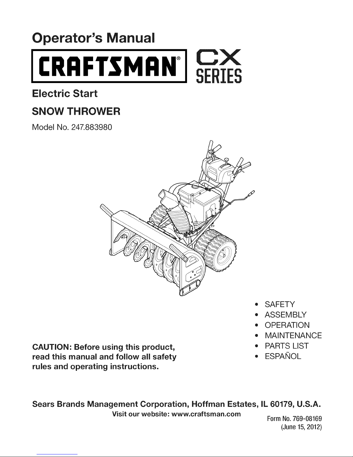
perator's nual
I:RRFrSMAN+
Electric Start
SNOW THROWER
Model No. 247.883980
CX
IES
CAUTION" Before using this product,
read this manual and follow all safety
rules and operating instructions.
Sears Brands Management Corporation, Hoffman Estates, IL 60179, U.S.A.
Visit our website: www.craftsman.com
,, SAFETY
, ASSEMBLY
OPERATION
MAINTENANCE
PARTS LIST
o ESPANOL
Form No.769-08169
(June 15,2012)
Page 2
Warranty Statement .................................. Page 2
Safe Operation Practices .......................... Page 3
Safety Labels ............................................ Page 7
Assembly .................................................. Page 8
Operation .................................................. Page 14
Service and Maintenance ......................... Page 19
Off-Season Storage .................................. Page 27
Troubleshooting ........................................ Page 28
Parts List ................................................... Page 29
Repair Protection Agreement ................... Page 40
Espa_ol ..................................................... Page 41
Service Numbers ...................................... Back Cover
CRAFTSMANCXTWOYEARFULLWARRANTY
FORTWOYEARSfromthe dateofpurchase,thisproductiswarrantedagainstanydefectsin materialor workmanship.A defective
productwillreceivefree repairorreplacementif repairisunavailable.
Forwarrantycoveragedetailstoobtainfreerepairorreplacement,visitthe website: www.craftsman.com
ThiswarrantycoversONLYdefectsin materialandworkmanship.Warrantycoverage doesNOTinclude:
• Expendableitemsthatcanwearoutfromnormalusewithinthewarrantyperiod,includingbutnotlimitedtoaugers,augerpaddles,
driftcutters,skidshoes,shaveplate,shearpins,sparkplug,aircleaner,belts,andoil filter.
• Standardmaintenanceservicing,oilchanges,or tune-ups.
Tirereplacementor repaircausedby puncturesfromoutsideobjects,suchasnails,thorns,stumps,orglass.
• Tireor wheelreplacementor repairresultingfromnormalwear,accident,orimproperoperationormaintenance.
Repairsnecessarybecauseofoperatorabuse,includingbutnotlimitedtodamagecausedbyover-speedingtheengine,or from
impactingobjectsthat bendtheframe,augershaft,etc.
• Repairsnecessarybecauseofoperatornegligence,includingbutnotlimitedto,electricaland mechanicaldamagecausedby
improperstorage,failureto usethepropergradeandamountof engineoil,or failuretomaintaintheequipmentaccordingtothe
instructionscontainedintheoperator'smanual.
• Engine(fuelsystem)cleaningorrepairscausedbyfuel determinedtobecontaminatedor oxidized(stale).ingeneral,fuelshouldbe
usedwithin30 daysofitspurchasedate.
Normaldeteriorationandwearofthe exteriorfinishes,orproductlabelreplacement.
Thiswarrantyisvoidif thisproductiseverusedwhileprovidingcommercialservicesor if rentedto anotherperson.
Thiswarrantygivesyouspecificlegalrights,andyoumayalsohaveotherrightswhichvaryfromstatetostate.
SearsBrands ManagementCorporation, HoffmanEstates,IL 60179
EngineOilType: 5W-30
EngineOilCapacity: 37ounces
FuelCapacity: Approx.5 Quarts
SparkPlug: F6RTC(951-10292)
SparkPlugGap: .020"to.030"
©SearsBrands,LLC
ModelNumber.................................................................
Serial Number.................................................................
Dateof Purchase.............................................................
Recordthemodelnumber,serialnumber
anddateof purchaseabove
2
Page 3
Thissymbolpointsout importantsafetyinstructionswhich,if not
followed,couldendangerthepersonalsafetyand/orpropertyof
yourselfandothers. Readandfollowall instructionsin thismanual
beforeattemptingtooperatethismachine.Failuretocomplywith
theseinstructionsmayresultin personalinjury.Whenyouseethis
symbol,HEEDITSWARNING!
Thismachinewasbuiltto beoperatedaccordingtothesafeopera-
tionpracticesinthis manual.Aswithanytypeof powerequipment,
carelessnessorerroron thepartofthe operatorcanresultin serious
injury.Thismachineiscapableofamputatingfingers,hands,toes
andfeetandthrowingdebris.Failuretoobservethefollowingsafety
instructionscouldresultin seriousinjuryor death.
CALIFORNIA PROPOSITION 65
EngineExhaust,someof itsconstituents,andcertainvehicle
componentscontainoremitchemicalsknowntoStateof California
tocausecancerandbirthdefectsorotherreproductiveharm,
TRAiNiNG
• Read,understand,andfollowall instructionson themachineand
in themanual(s)beforeattemptingto assembleandoperate.
Failuretodo socan resultinseriousinjurytotheoperatorand/
orbystanders.Keepthismanualin asafeplaceforfutureand
regularreferenceandfororderingreplacementparts.
• Befamiliarwithall controlsandtheirproperoperation.Knowhow
tostopthe machineanddisengagethemquickly.
• Neverallowchildrenunder14yearsofageto operatethis
machine.Children14andovershouldreadandunderstandthe
instructionsandsafeoperationpracticesin thismanualandon
themachineandbe trainedandsupervisedbyanadult.
Neverallowadultsto operatethismachinewithoutproper
instruction.
• Thrownobjectscan causeseriouspersonalinjury.Planyour
snow-throwingpatterntoavoiddischargeof materialtoward
roads,bystandersandthelike.
Keepbystanders,petsandchildrenat least75feetfromthe
machinewhileit isin operation.Stopmachineifanyoneenters
thearea.
• Exercisecautiontoavoidslippingor falling,especiallywhen
operatinginreverse.
Your Responsibility--Restrict theuseofthispowermachineto
personswhoread,understandandfollowthewarningsand instruc-
tionsin thismanualandon themachine.
SAVE THESE INSTRUCTIONS!
PREPARATION
Thoroughlyinspecttheareawheretheequipmentistobeused.
Removeall doormats,newspapers,sleds,boards,wiresandother
foreignobjects,whichcouldbe trippedoverorthrownbytheauger/
impeller.
• Alwayswearsafetyglassesoreyeshieldsduringoperationand
whileperformingan adjustmentor repairto protectyoureyes.
Thrownobjectswhichricochetcancauseseriousinjurytothe
eyes.
Donot operatewithoutwearingadequatewinteroutergarments.
Donot wearjewelry,longscarvesorotherlooseclothing,which
couldbecomeentangledin movingparts.Wearfootwearwhich
willimprovefootingonslipperysurfaces.
Usea groundedthree-wireextensioncordand receptacleforall
machineswithelectricstartengines.
Disengageall controlleversbeforestartingtheengine.
Adjustcollectorhousingheightto cleargravelorcrushedrock
surfaces.
• Neverattempttomakeanyadjustmentswhileengineis running,
exceptwherespecificallyrecommendedinthe operator'smanual.
Letengineandmachineadjustto outdoortemperaturebefore
startingtoclearsnow.
3
Page 4
SafeHandling of Gasoline
Toavoidpersonalinjuryor propertydamageuseextremecarein
handlinggasoline.Gasolineisextremelyflammableandthevaporsare
explosive.Seriouspersonalinjurycan occurwhengasolineisspilled
onyourselforyourclotheswhichcan ignite.Washyourskinand
changeclothesimmediately.
• Useonlyan approvedgasolinecontainer.
• Extinguishallcigarettes,cigars,pipesandothersourcesof
ignition.
• Neverfuelmachineindoors.
• Neverremovegascapor addfuelwhiletheengineishotor
running.
• Allowengineto coolat leasttwo minutesbeforerefueling.
• Neveroverfill fueltank.Filltankto nomorethan1/2inchbelow
bottomoffillerneckto providespaceforfuelexpansion.
• Replacegasolinecapandtightensecurely.
• Ifgasolineis spilled,wipeitofftheengineandequipment.Move
machinetoanotherarea.Wait5 minutesbeforestartingthe
engine.
• Neverstorethemachineorfuel containerinsidewherethereisan
openflame,sparkor pilotlight(e.g.furnace,waterheater,space
heater,clothesdryeretc.).
• Allowmachinetocoolat least5minutesbeforestoring.
• Neverfillcontainersinsideavehicleor ona truckortrailerbed
witha plasticliner.Alwaysplacecontainersonthegroundaway
fromyourvehiclebeforefilling.
• If possible,removegas-poweredequipmentfromthe truckor
trailerandrefuelitonthe ground.Ifthis isnotpossible,thenrefuel
suchequipmenton a trailerwithaportablecontainer,ratherthan
froma gasolinedispensernozzle.
• Keepthenozzlein contactwiththerimofthefueltankor
containeropeningatalltimes untilfuelingiscomplete.Donotuse
a nozzlelock-opendevice.
OPERATION
• Donot puthandsorfeetnearrotatingparts,in theauger/impeller
housingorchuteassembly.Contactwiththerotatingpartscan
amputatehandsandfeet.
• Theauger/impellercontrolleverisa safetydevice.Neverbypass
itsoperation.Doingsomakesthe machineunsafeandmaycause
personalinjury.
• Thecontrolleversmustoperateeasilyinbothdirectionsand
automaticallyreturntothedisengagedpositionwhenreleased.
• Neveroperatewitha missingordamagedchuteassembly.Keep
all safetydevicesinplaceandworking.
• Neverrunanengineindoorsorina poorlyventilatedarea.Engine
exhaustcontainscarbonmonoxide,anodorlessanddeadlygas.
• Donotoperatemachinewhileundertheinfluenceofalcoholor
drugs.
• Mufflerandenginebecomehotandcancausea burn.Donot
touch.Keepchildrenaway.
• Exerciseextremecautionwhenoperatingon orcrossinggravel
surfaces.Stayalertforhiddenhazardsortraffic.
Exercisecautionwhenchangingdirectionandwhileoperatingon
slopes.Do notoperateonsteepslopes.
Planyoursnow-throwingpatternto avoiddischargetowards
windows,walls,carsetc. Thus,avoidingpossibleproperty
damageorpersonalinjurycausedby aricochet.
Neverdirectdischargeatchildren,bystandersand petsor allow
anyoneinfrontof themachine.
Donot overloadmachinecapacitybyattemptingtoclearsnowat
toofastof a rate.
Neveroperatethismachinewithoutgoodvisibilityorlight.Always
be sureofyourfootingand keepafirmholdon the handles.Walk,
neverrun.
Disengagepowertotheauger/impellerwhentransportingor not
in use.
Neveroperatemachineathightransportspeedsonslippery
surfaces.Lookdownand behindandusecarewhenbackingup.
Ifthemachineshouldstartto vibrateabnormally,stoptheengine,
disconnectthesparkplugwire andgrounditagainsttheengine.
Inspectthoroughlyfordamage.Repairanydamagebefore
startingandoperating.
Disengageall controlleversandstopenginebeforeyouleave
theoperatingposition(behindthehandles).Waituntiltheauger/
impellercomestoa completestopbeforeuncloggingthechute
assembly,makinganyadjustments,or inspections.
Neverputyourhandinthedischargeorcollectoropenings.Do
notunclogchuteassemblywhileengineis running.Shutoff
engineand remainbehindhandlesuntilall movingpartshave
stoppedbeforeunclogging.
Useonlyattachmentsandaccessoriesapprovedbythemanufac-
turer(e.g.wheelweights,tirechains,cabsetc.). Forinformation
concerningtheseitems,call1-800-469-4663.
Whenstartingengine,pullcord slowlyuntilresistanceis felt,then
pull rapidly.Rapidretractionof startercord(kickback)willpull
handandarmtowardenginefasterthanyoucanletgo.Broken
bones,fractures,bruisesorsprainscouldresult.
Ifsituationsoccurwhichare notcoveredinthis manual,usecare
andgoodjudgment.
Toorderpartsor scheduleserviceforthisproduct,call 1-800-
469-4663.
CLEARING A CLOGGED DISCHARGE CHUTE
Handcontactwiththe rotatingimpellerinsidethedischargechute
is themostcommoncauseofinjuryassociatedwithsnowthrowers.
Neveruseyourhandtocleanoutthedischargechute.
Toclear thechute:
1. SHUTTHEENGINEOFF!
2. Wait 10secondstobe surethe impellerbladeshavestopped
rotating.
3. Alwaysusea clean-outtool,notyourhands.
4
Page 5
MAINTENANCE & STORAGE
• Nevertamperwithsafetydevices.Checktheirproperoperation
regularly.Refertothe maintenanceandadjustmentsectionsof
thismanual.
• Beforecleaning,repairing,or inspectingmachinedisengageall
controlleversandstoptheengine.Waituntilthe auger/impeller
cometoa completestop.Disconnectthe sparkplugwireand
groundagainsttheengineto preventunintendedstarting.
Checkboltsand screwsforpropertightnessatfrequentintervals
tokeepthemachineinsafeworkingcondition.Also,visually
inspectmachineforanydamage.
Donotchangetheenginegovernorsettingor over-speedthe
engine.Thegovernorcontrolsthe maximumsafeoperatingspeed
ofthe engine.
Snowthrowershaveplatesandskidshoesaresubjecttowear
anddamage.Foryoursafetyprotection,frequentlycheckall
componentsand replacewithoriginalequipmentmanufacturer's
(OEM)partsonlyaslistedinthe Partspagesof thisoperator's
manual.Useofpartswhichdonot meettheoriginalequipment
specificationsmayleadto improperperformanceandcompro-
misesafety!
Checkcontrolleversperiodicallytoverifytheyengageanddisen-
gageproperlyandadjust,ifnecessary.Refertothe adjustment
sectioninthisoperator'smanualforinstructions.
Maintainor replacesafetyandinstructionlabels,asnecessary.
Observeproperdisposallawsand regulationsfor gas,oil,etc.to
protecttheenvironment.
Priorto storing,runmachinea few minutestoclearsnowfrom
machineand preventfreezeupof auger/impeller.
Neverstorethemachineorfuel containerinsidewherethereisan
openflame,sparkorpilot lightsuchasawaterheater,furnace,
clothesdryeretc.
Alwaysrefertothe operator'smanualforproperinstructionson
off-seasonstorage.
Checkfuelline,tank, cap,andfittingsfrequentlyforcracksor
leaks.Replaceif necessary.
Donotcrankenginewithsparkplugremoved.
Accordingtothe ConsumerProductsSafetyCommission(CPSC)
andtheU.S.EnvironmentalProtectionAgency(EPA),thisproduct
hasan AverageUsefulLifeof seven(7)years,or60hoursof
operation.Atthe endoftheAverageUsefulLifehavethemachine
inspectedannuallybyan authorizedservicedealerto ensurethat
allmechanicalandsafetysystemsareworkingproperlyand not
wornexcessively.Failuretodoso canresultinaccidents,injuries
ordeath.
DO NOT MODIFY ENGINE
Toavoidseriousinjuryor death,do notmodifyengineinanyway.
Tamperingwiththe governorsettingcanleadto arunawayengineand
causeitto operateatunsafespeeds.Nevertamperwithfactorysetting
ofenginegovernor.
NOTICE REGARDING EMiSSiONS
EngineswhicharecertifiedtocomplywithCaliforniaandfederal
EPAemissionregulationsforSORE(SmallOffRoadEquipment)are
certifiedto operateonregularunleadedgasoline,and mayinclude
thefollowingemissioncontrolsystems:EngineModification(EM),
OxidizingCatalyst(OC),SecondaryAirInjection(SAI)and ThreeWay
Catalyst(TWO)if so equipped.
SPARK ARRESTOR
Thismachineisequippedwithaninternalcombustionengineand
shouldnotbe usedonor nearanyunimprovedforest-covered,
brush-coveredorgrass-coveredlandunlesstheengine'sexhaust
systemisequippedwitha sparkarrestormeetingapplicablelocalor
statelaws(if any)
Ifa sparkarrestorisused,itshouldbe maintainedineffectiveworking
orderbytheoperator.Inthe StateofCaliforniatheaboveis required
bylaw (Section4442oftheCaliforniaPublicResourcesCode).Other
statesmayhavesimilarlaws. Federallawsapplyonfederallands.
A sparkarrestorfor themufflerisavailablethroughyournearestSears
PartsandRepairServiceCenter.
Page 6
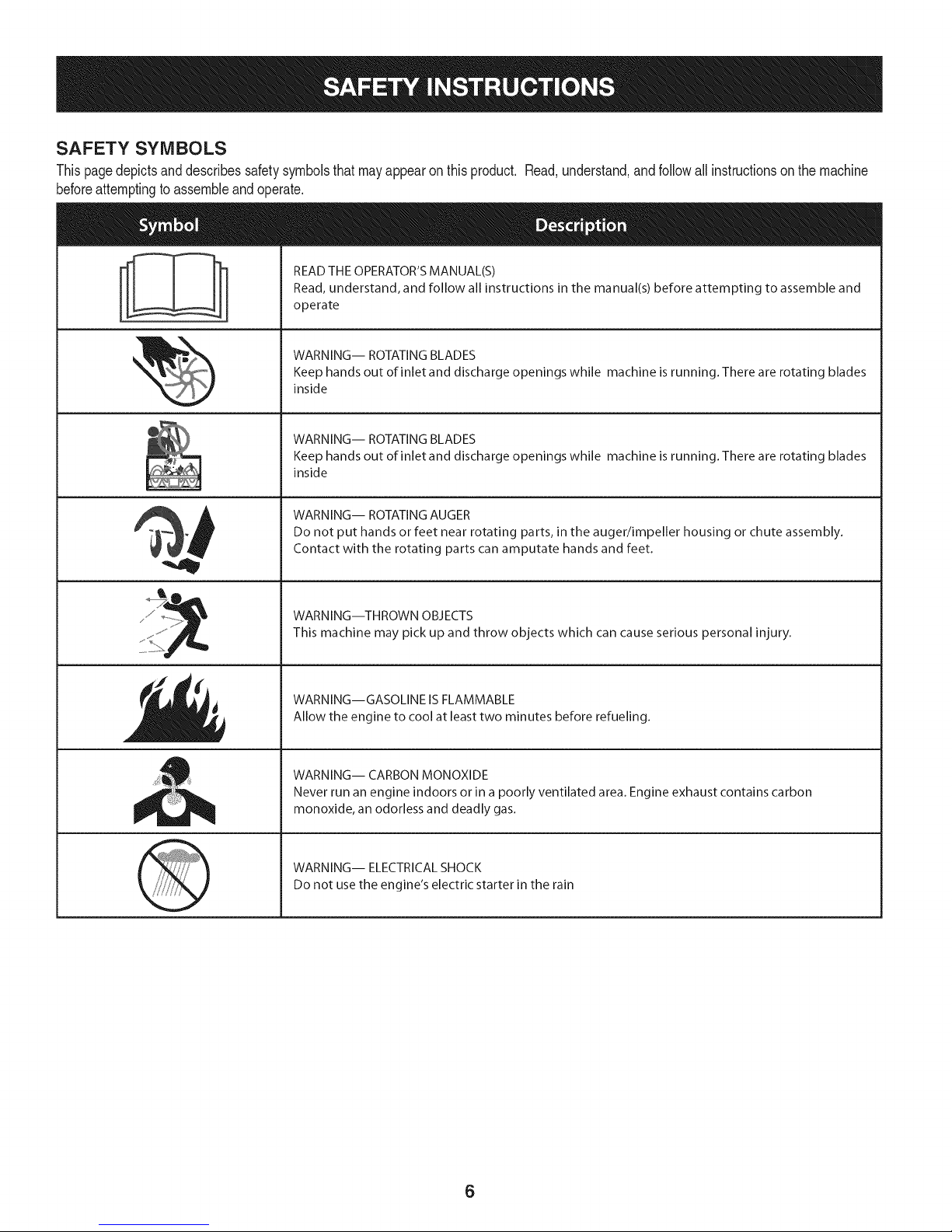
SAFETY SYMBOLS
Thispagedepictsanddescribessafetysymbolsthatmayappearonthisproduct. Read,understand,andfollowall instructionson the machine
beforeattemptingtoassembleandoperate.
READ THE OPERATOR'S MANUAL(S)
i
. +
i
Read, understand, and follow all instructions in the manual(s) before attempting to assemble and
operate
WARNING-- ROTATING BLADES
Keep hands out of inlet and discharge openings while machine is running. There are rotating blades
inside
WARNING-- ROTATING BLADES
Keep hands out of inlet and discharge openings while machine is running. There are rotating blades
inside
WARNING-- ROTATING AUGER
Do not put hands or feet near rotating parts, in the auger/impeller housing or chute assembly.
Contact with the rotating parts can amputate hands and feet.
'JIp
WARNING--THROWN OBJECTS
This machine may pick up and throw objects which can cause serious personal injury.
WARNING--GASOLINE IS FLAMMABLE
Allow the engine to cool at least two minutes before refueling.
WARNING-- CARBON MONOXIDE
Never run an engine indoors or in a poorly ventilated area. Engine exhaust contains carbon
monoxide, an odorless and deadly gas+
WARNING-- ELECTRICAL SHOCK
Do not use the engine's electric starter in the rain
6
Page 7
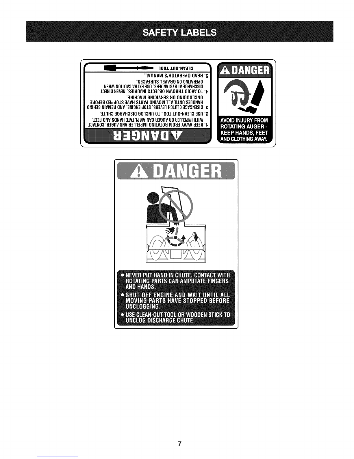
r
100/.LIIO-NV:IIO
"lVflNV_ S,UOIVU3dOQV3H"G
"S3OV_IJflS]3AVUONO9NIIV_J3dO
N3HMNOIIflVOVSIX]qsfl"S9]ONVIS181V]98VHOSIO
10381083A3N'S]IUflrNI SI03PgoNMOUHIQIOAV01"_
"3NIHOV_ONIOIA83SUOONIOOO]ONfl
]UO_38O3ddOIS]AVHSlHPd9NIAOW11VlllNfl S]IQNVH
ONIH]8NIVW3UONV']NION]dOlS'88]A]1HOlnlo]9VON]SIO"8
"]lnHg ]gHVHOSIO9010Nfl01 1001lflO-NP]lO ]Sfl "Z
"l]]d ONVSONVH]lPlnd_P NVOH3onvuoHq]l]d_JIHIIM
IOVINO0"u39npONV_J3113dWI9NllVIOU_JOH_IVMVd]3H "L
7
Page 8
NOTE:Referencesto rightorleft sideof thesnowthrowerare
determinedfromthe operatingpositionlookingforwardtothe frontof
themachine.
REMOVING FROM CRATE
1. Removescrewsfromthebottomof thecratesecuringthesides,
andendsof theshippingcrate.
2. Liftoff thetopoff ofthe crateandsetoutof thewayofthe
assemblyarea.
3. Removeanddiscardplasticbagthatcoversunit.
4. Removeanyloosepartsincludedwithunit(e.g.,Operator's
Manual,etc.).
5. Pushdownonthelowerhandleandpullunitbackout ofcrate.
6. Makecertainthecratehas beencompletelyemptiedbefore
discardingit.
ASSEMBLY
1. Makecertainthe springsatthelowerendofthe augeranddrive
cablesaresecurelyhookedintotheir respectiveactuator
bracketsbeforepivotingthehandleupward.Referto Fig. 10.
a. Placethe speedselectorshiftleverin theF6 position.
b. Cutthecabletiesecuringthetwo piecechutecrankto the
lowerhandle.Thecable tieisusedforshippingpurposes.
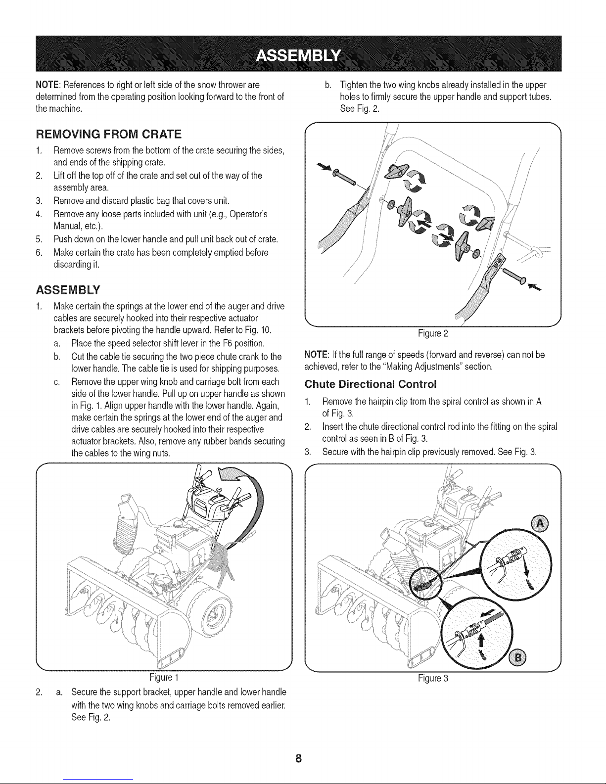
c. Removethe upperwingknobandcarriageboltfromeach
sideof thelowerhandle.Pulluponupperhandleasshown
in Fig.1.Alignupperhandlewiththelowerhandle.Again,
makecertainthespringsat thelowerendoftheaugerand
drivecablesaresecurelyhookedintotheirrespective
actuatorbrackets.Also,removeanyrubberbandssecuring
thecablesto thewingnuts.
Tightenthetwowingknobsalreadyinstalledinthe upper
holesto firmlysecuretheupperhandleandsupporttubes.
See Fig.2.
f
!
{
/
/
Figure2
NOTE:Ifthe fullrangeofspeeds(forwardandreverse)cannotbe
achieved,refertothe "MakingAdjustments"section.
Chute Directional Control
1. Removethehairpinclipfromthespiralcontrolas showninA
of Fig.3.
2. Insertthechutedirectionalcontrolrodintothefittingonthe spiral
controlas seeninBof Fig.3.
3. Securewiththe hairpinclippreviouslyremoved.SeeFig.3.
\
Figure1
2.
a.
Securethesupportbracket,upperhandleandlowerhandle
withthetwo wingknobsandcarriageboltsremovedearlier.
SeeFig.2.
Figure3
8
Page 9
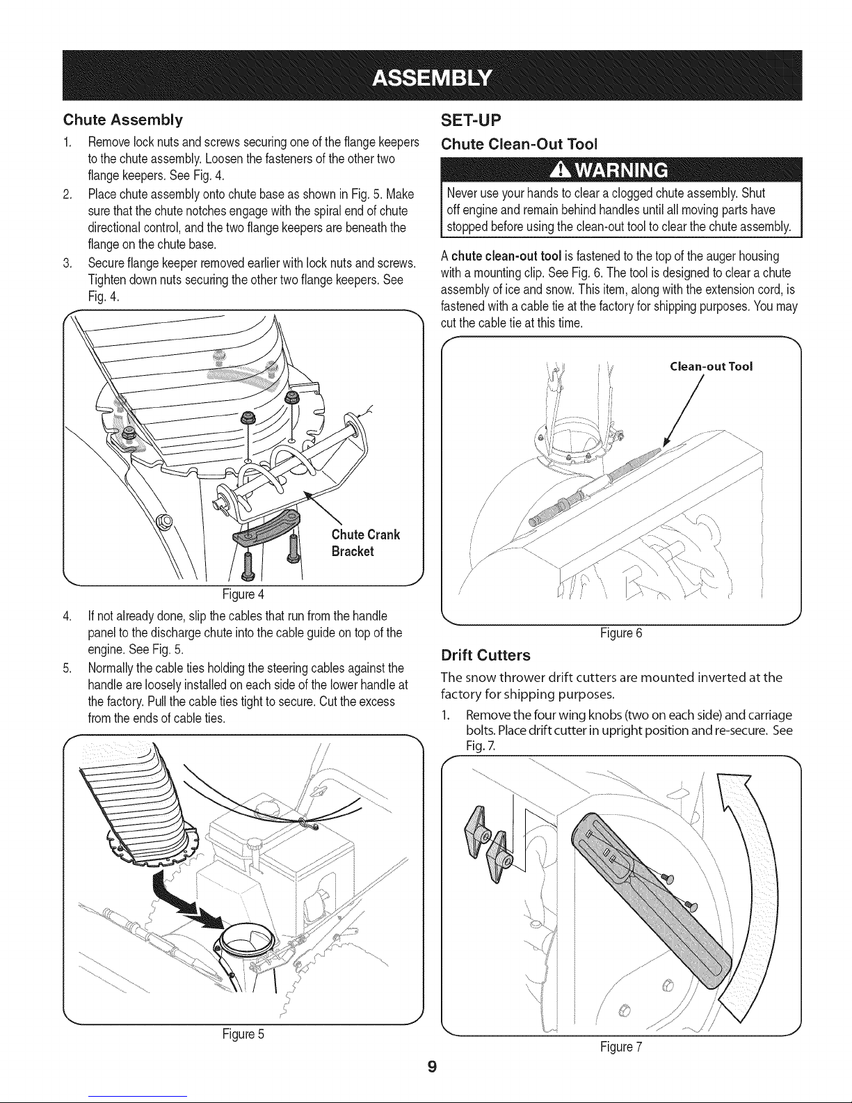
Chute Assembly
1, Removelocknutsandscrewssecuringoneof theflangekeepers
tothe chuteassembly,Loosenthefastenersoftheothertwo
flangekeepers,SeeFig,4,
2, Placechuteassemblyontochutebaseas showninFig,5,Make
surethatthe chutenotchesengagewiththespiralendofchute
directionalcontrol,andthe twoflangekeepersarebeneaththe
flangeonthe chutebase,
3, Secureflangekeeperremovedearlierwithlocknutsandscrews,
Tightendownnutssecuringtheothertwoflangekeepers.See
Fig.4.
SET-UP
Chute Clean=Out Tool
Neveruseyourhandsto cleara cloggedchuteassembly.Shut
offengineand remainbehindhandlesuntilall movingpartshave
stoppedbeforeusingtheclean-outtooltoclearthechuteassembly,
A chuteclean-outtool is fastenedtothetopoftheaugerhousing
witha mountingclip. SeeFig.6. Thetoolisdesignedtoclearachute
assemblyofice andsnow.Thisitem,alongwiththeextensioncord,is
fastenedwitha cabletieatthefactoryforshippingpurposes.Youmay
cut thecabletieatthistime.
Clean=out Tool
Figure4
.
If notalreadydone,slipthecablesthat runfromthehandle
paneltothe dischargechuteintothecableguideontopof the
engine.SeeFig.5.
.
Normallythecabletiesholdingthe steeringcablesagainstthe
handlearelooselyinstalledoneachsideofthe lowerhandleat
thefactory.Pullthecableties tighttosecure.Cuttheexcess
fromtheendsof cableties.
\,
//
//
(,
Figure6
Drift Cutters
The snow thrower drift cutters are mounted inverted at the
factory for shipping purposes.
1. Removethe four wing knobs (twooneachside)andcarriage
bolts.Placedrift cutter in upright positionand re-secure.See
Fig.7.
ii
J
J
Figure7
9
Page 10
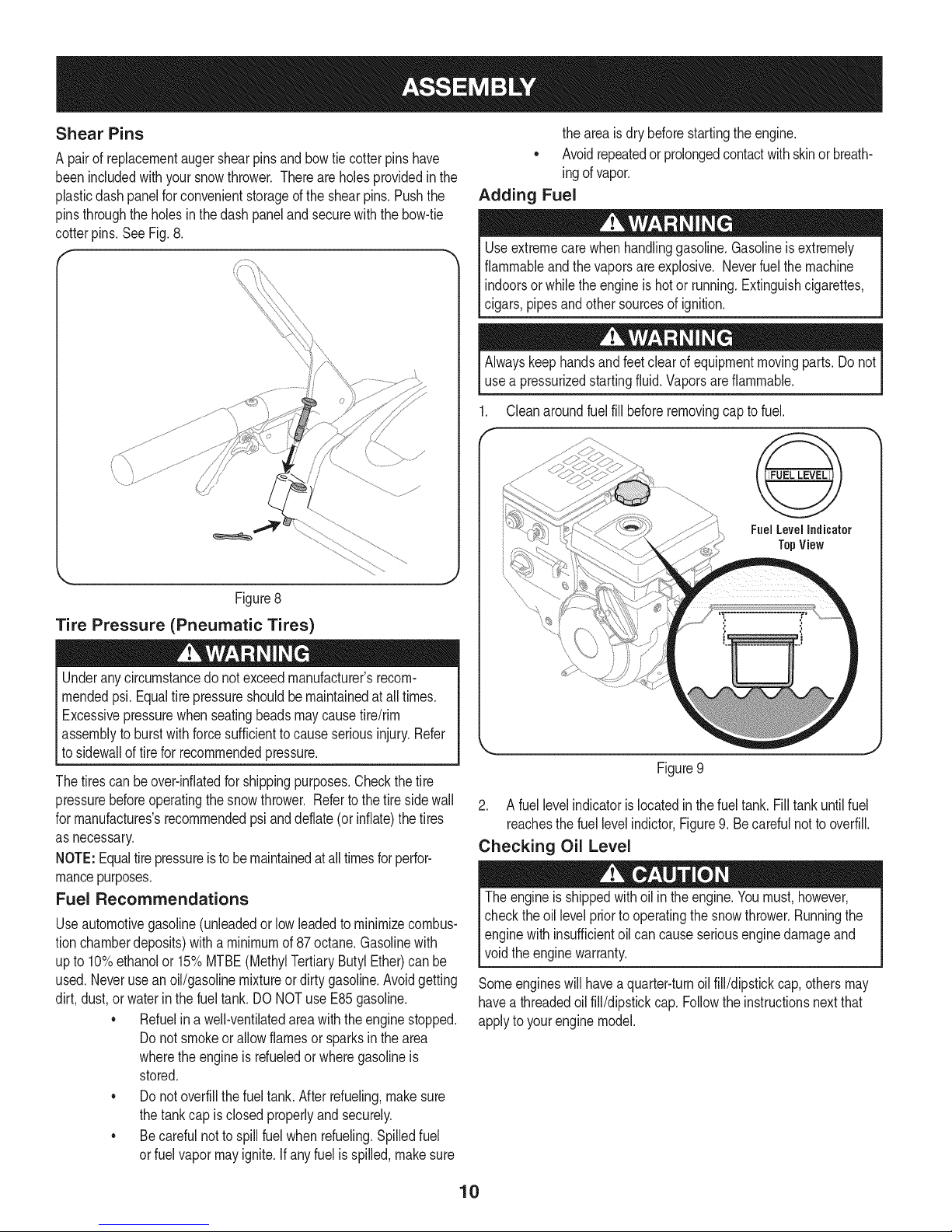
Shear Pins
A pairof replacementaugershearpinsandbowtiecotterpinshave
beenincludedwithyour snowthrower.Thereareholesprovidedinthe
plasticdashpanelforconvenientstorageofthe shearpins.Pushthe
pinsthroughtheholesin thedashpanelandsecurewiththebow-tie
cotterpins.See Fig.8.
theareais drybeforestartingtheengine.
• Avoidrepeatedor prolongedcontactwithskinorbreath-
ingofvapor.
Adding Fuel
Useextremecarewhenhandlinggasoline.Gasolineisextremely
flammableandthe vaporsareexplosive.Neverfuelthemachine
indoorsorwhile theengineishotor running.Extinguishcigarettes,
cigars,pipesandothersourcesofignition.
Alwayskeephandsandfeetclear ofequipmentmovingparts.Donot
usea pressurizedstartingfluid.Vaporsareflammable.
Cleanaroundfuel fillbeforeremovingcap tofuel.
Fuel Level Indicator
TopView
Figure8
Tire Pressure (Pneumatic Tires)
Underanycircumstancedo notexceedmanufacturer'srecom-
mendedpsi.Equaltire pressureshouldbemaintainedatalltimes.
Excessivepressurewhenseatingbeadsmaycausetire/rim
assemblytoburstwithforcesufficienttocauseseriousinjury.Refer
to sidewalloftireforrecommendedpressure.
Thetirescan beover-inflatedforshippingpurposes.Checkthetire
pressurebeforeoperatingthesnowthrower. Refertothetiresidewall
for rnanufactures'srecommendedpsianddeflate(or inflate)thetires
as necessary.
NOTE:Equaltirepressureisto bemaintainedat alltimesforperfor-
mancepurposes.
Fuel Recommendations
Useautomotivegasoline(unleadedor lowleadedto minimizecombus-
tionchamberdeposits)witha minimumof87 octane.Gasolinewith
upto 10%ethanolor15%MTBE(MethylTertiaryButylEther)canbe
used.Neverusean oil/gasolinemixtureordirtygasoline.Avoidgetting
dirt, dust,or waterinthefueltank.DO NOTuseE85gasoline.
• Refuelina well-ventilatedareawiththeenginestopped.
Donot smokeorallowflamesor sparksinthearea
wherethe engineis rdueledor wheregasolineis
stored.
• Donotoverfillthefueltank.Afterrefueling,makesure
thetankcap isclosedproperlyandsecurely.
• Becarefulnottospillfuel whenrefueling.Spilledfuel
or fuelvapormayignite.Ifanyfuelis spilled,makesure
Figure9
2. A fuellevelindicatorislocatedinthe fueltank. Filltankuntilfuel
reachesthefuel levelindictor,Figure9.Becarefulnottooverfill.
Checking Oil Level
Theengineis shippedwithoil in theengine.Youmust,however,
checkthe oillevelpriorto operatingthesnowthrower.Runningthe
enginewith insufficientoil cancauseseriousenginedamageand
voidtheenginewarranty.
Someengineswillhavea quarter-turnoil fill/dipstickcap,othersmay
havea threadedoilfill/dipstickcap.Followthe instructionsnextthat
applyto yourenginemodel.
10
Page 11
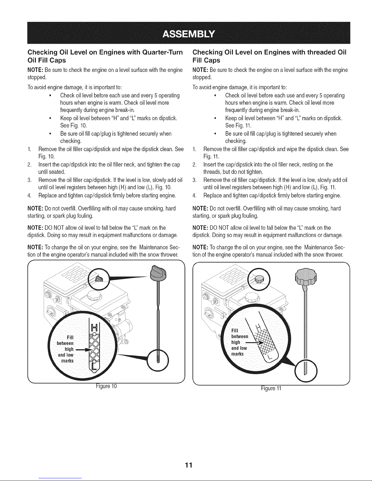
Checking Oil Level on Engines with Quarter=Turn
Oil Fill Caps
NOTE:Besuretochecktheengineona levelsurfacewiththeengine
stopped.
Toavoidenginedamage,itisimportantto:
• Checkoillevelbeforeeachuseandevery5 operating
hourswhenengineiswarm.Checkoillevelmore
frequentlyduringenginebreak-in.
• Keepoil levelbetween"H"and'%'marksondipstick.
SeeFig.10.
• Besureoil fillcap/plugistightenedsecurelywhen
checking.
1. Removetheoil fillercap/dipstickandwipethedipstickclean.See
Fig.10.
2. Insertthe cap/dipstickintotheoil fillerneck,andtightenthecap
untilseated.
3. Removetheoil fillercap/dipstick.Ifthelevelislow,slowlyaddoil
untiloil levelregistersbetweenhigh(H)andlow(L), Fig.10.
4. Replaceandtightencap/dipstickfirmlybeforestartingengine.
Checking Oil Level on Engines with threaded Oil
Fill Caps
NOTE:Besuretochecktheengineon a levelsurfacewiththeengine
stopped.
Toavoidenginedamage,itis importantto:
• Checkoillevelbeforeeachuseandevery5 operating
hourswhenengineiswarm.Checkoil levelmore
frequentlyduringenginebreak-in.
• Keepoillevelbetween"H"and"L"markson dipstick.
SeeFig.11.
• Besureoilfillcap/plugistightenedsecurelywhen
checking.
1. Removetheoilfillercap/dipstickandwipethedipstickclean.See
Fig.11.
2. Insertthecap/dipstickintothe oilfillerneck,restingon the
threads,butdo nottighten.
3. Removethe oilfillercap/dipstick.Ifthe levelislow,slowlyaddoil
untiloillevel registersbetweenhigh(H)andlow (L),Fig.11.
4. Replaceandtightencap/dipstickfirmlybeforestartingengine.
NOTE:Donotoverfill.Overfillingwithoil maycausesmoking,hard
starting,or sparkplugfouling.
NOTE:DONOTallowoil leveltofallbelowthe"L"markonthe
dipstick.Doingsomayresultinequipmentmalfunctionsordamage.
NOTE:Tochangethe oilonyourengine,seethe MaintenanceSec-
tionof theengineoperator'smanualincludedwiththesnowthrower.
NOTE:Do notoverfill.Overfillingwithoil maycausesmoking,hard
starting,or sparkplugfouling.
NOTE:DO NOTallowoil leveltofallbelowthe"L"markon the
dipstick.Doingsomayresultinequipmentmalfunctionsor damage.
NOTE:Tochangetheoil onyourengine,seethe MaintenanceSec-
tionof theengineoperator'smanualincludedwiththe snowthrower.
Figure10
Figure11
11
Page 12
ADJUSTMENTS
Skid Shoes
Itisnot recommendedthatyouoperatethissnowthrowerongravel
asit caneasilypickupandthrowloosegravel,causingpersonal
injuryor damagetothesnowthrowerandsurroundingproperty.
Thesnowthrowerskidshoesareadjustedupwardatthefactory
forshippingpurposes.Adjustthemdownwardpriortooperatingthe
machine.
Forclosesnowremovalona smoothsurface,adjustthe skidshoesso
thattheshaveplateonthebottomof the augerhousingisjustoffthe
ground.
Adjusttheskidshoesto alowerpositiontoraisetheshaveplateoff the
groundwhenclearingunevenareas,suchas aribbontypedrivewayor
agraveldriveway
NOTE:If youchoosetooperatethesnowthrowerona gravelsurface,
keepthe skidshoesinpositionformaximumclearancebetweenthe
groundandtheshaveplate.
To adjust the skid shoes:
1. Adjustskidshoesby looseningthesix(threeon eachside)hex
nutsandcarriagebolts securingtheskidshoestotheauger
housing. RefertoFigure12.
f
AUGER AND DRIVE CONTROL CABLES
Priortooperatingyoursnowthrower,carefullyreadandfollowall
instructionsbelow.Performalladjustmentsto verifyyoursnow
throwerisoperatingsafelyandproperly.
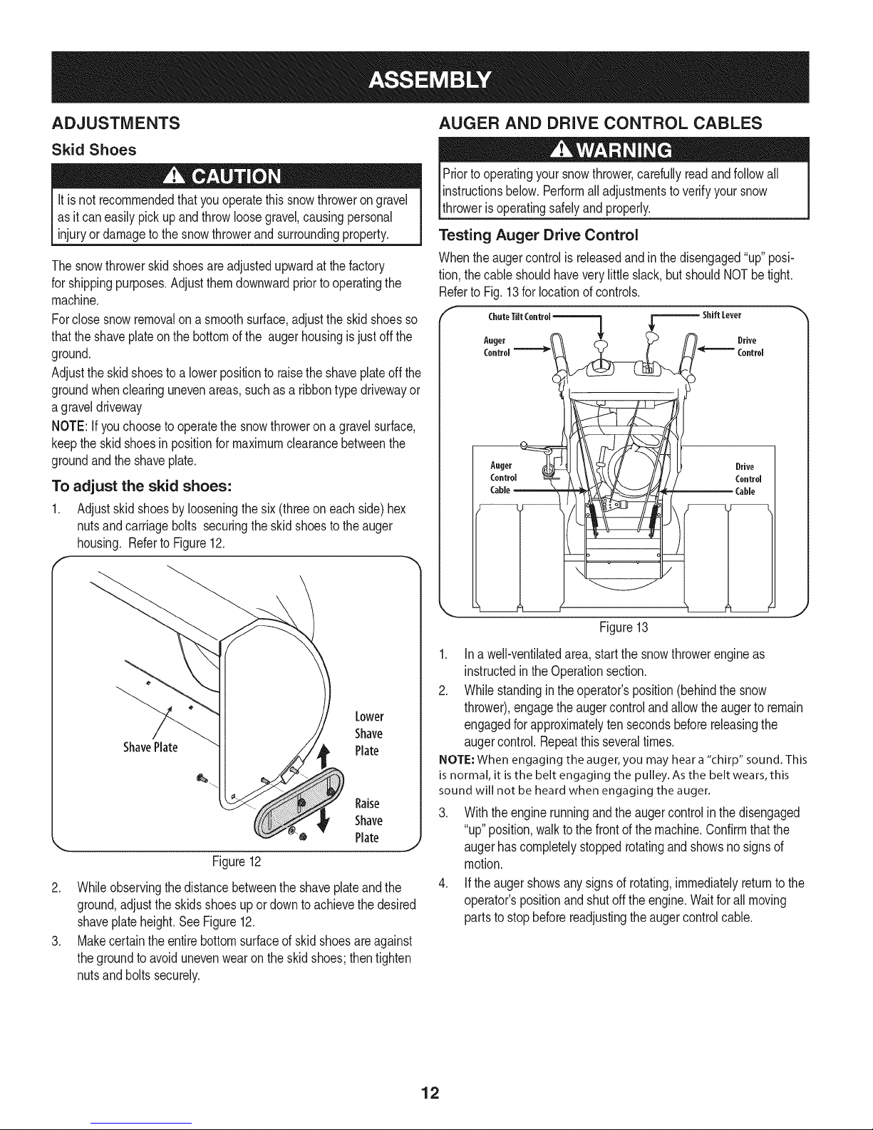
Testing Auger Drive Control
Whenthe augercontrolisreleasedandinthedisengaged"up" posi-
tion,thecableshouldhaveverylittleslack,butshouldNOTbetight.
RefertoFig.13for locationof controls.
r c,.,o,,,co..o,-.--=q F------'"'"Lev°'
A.ge, & n. O,,vo
X..__J_ H '°°"°'
Aoter _ Drive
, °'
Lower
Shave
ShavePlate
Figure12
2. Whileobservingthedistancebetweentheshaveplateand the
ground,adjusttheskidsshoesupor downtoachievethedesired
shaveplateheight.SeeFigure12.
3. Makecertaintheentirebottomsurfaceof skidshoesareagainst
thegroundto avoidunevenwearontheskidshoes;thentighten
nutsandboltssecurely.
Plate
Raise
Shave
Plate
Figure13
1. Ina well-ventilatedarea,startthesnowthrowerengineas
instructedintheOperationsection.
2. Whilestandinginthe operator'sposition(behindthesnow
thrower),engagetheaugercontrolandallowthe augerto remain
engagedforapproximatelytensecondsbeforereleasingthe
augercontrol.Repeatthisseveraltimes.
NOTE: When engaging the auger, you may hear a "chirp" sound. This
is normal, it is the belt engaging the pulley. As the belt wears, this
sound will not be heard when engaging the auger.
3. Withtheenginerunningandthe augercontrolin thedisengaged
"up"position,walktothe frontofthe machine.Confirmthatthe
J
augerhascompletelystoppedrotatingandshowsnosignsof
motion.
4. Iftheaugershowsanysignsof rotating,immediatelyreturntothe
operator'spositionandshutofftheengine.Waitforall moving
partstostopbeforereadjustingthe augercontrolcable.
12
Page 13
Testing Wheel Drive Control & Speed Selector Lever
RefertoFig.13forlocationofcontrols.
1. Movethespeedselectorshiftleverintosixth(6)position.
2. Withthewheeldrivecontrolreleased,pushthesnowthrowerforward,
thenpullitback.Themachineshouldmovefreely.
3. Engagethedrivecontrolandattempttomovethemachineboth
forwardandback,resistanceshouldbefelt.
4. Movethespeedselectorshiftleverintothefastreverse(R2)position
andrepeattheprevioustwosteps.
Ifyouexperiencedresistancerollingtheunit,eitherwhenrepositioning
thespeedselectorshiftleverfrom6toR2orwhenattemptingtomovethe
machinewiththedrivecontrolreleased,adjustthedrivecontrolimmedi-
ately.SeeAdjustingDriveandAugerControls.
Adjusting Wheel Drive & Auger Controls
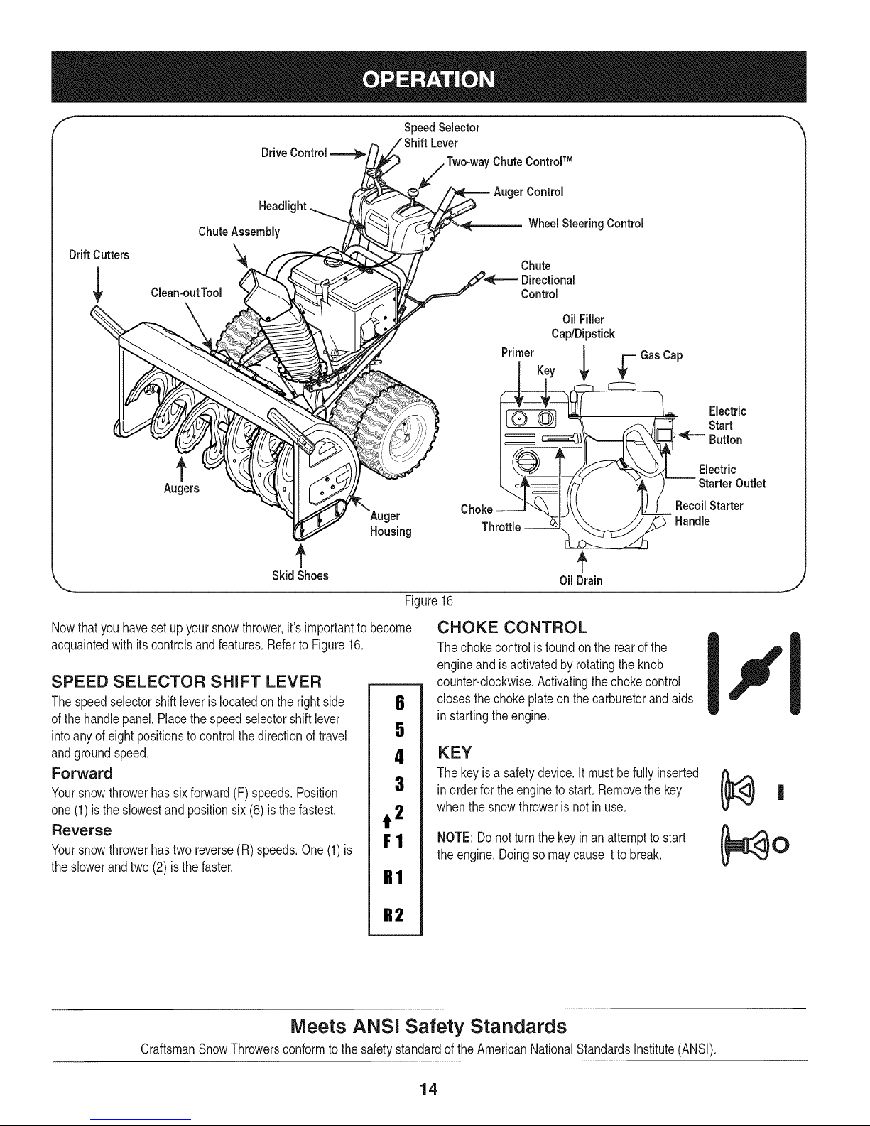
1. Frombeneaththehandle,pulldownwardontheappropriatecable
andunhookthespringfoundontheendofthecablefromits
respectiveactuatorbracket.RefertoFig.14.
J
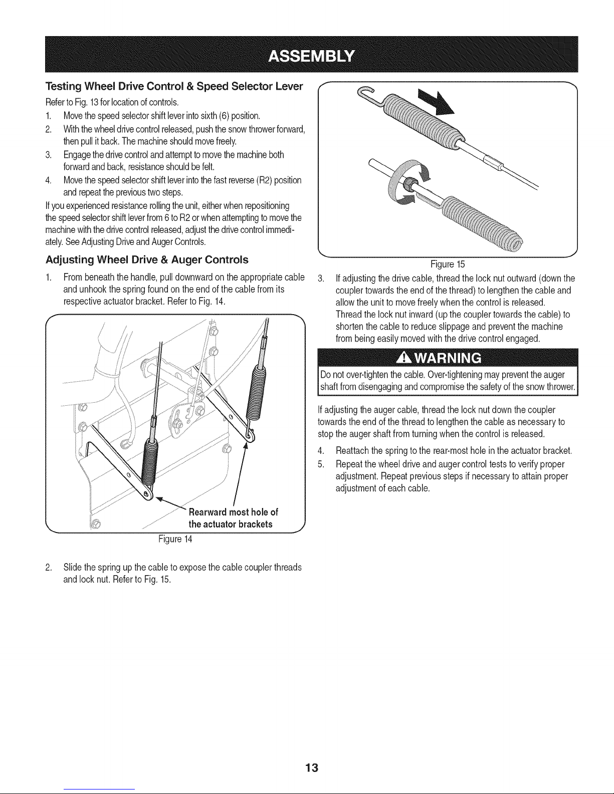
Figure15
Ifadjustingthedrivecable,threadthelock nutoutward(downthe
couplertowardstheend ofthethread)tolengthenthecableand
allowthe unittomovefreelywhenthecontrolis released.
Threadthe locknutinward(upthecouplertowardsthecable)to
shortenthecableto reduceslippageandpreventthemachine
frombeingeasilymovedwiththedrive controlengaged.
Donotover-tightenthecable.Over-tighteningmaypreventtheauger
shaftfromdisengagingandcompromisethesafetyofthesnowthrower.
b_ Rearwardmost holeof
\.. theactuator brackets .1)
Figure14
2. Slidethespringup thecableto exposethecablecouplerthreads
andlocknut. Referto Fig.15.
Ifadjustingtheaugercable,threadthe locknutdownthecoupler
towardstheendofthe threadtolengthenthecableasnecessaryto
stoptheaugershaftfromturningwhenthecontrolis released.
4. Reattachthespringtothe rear-mostholeintheactuatorbracket.
5. Repeatthewheeldriveandaugercontrolteststo verifyproper
adjustment.Repeatpreviousstepsifnecessarytoattainproper
adjustmentofeachcable.
13
Page 14
"I- SpeedSelector '_
Lever
Drive 'Chute ControlTM
Control
Headli_
ChuteAssembly
WheelSteeringControl
Drift Cutters '_
Clean-outTool
Augers
\Auger
Housing
f
SkidShoes
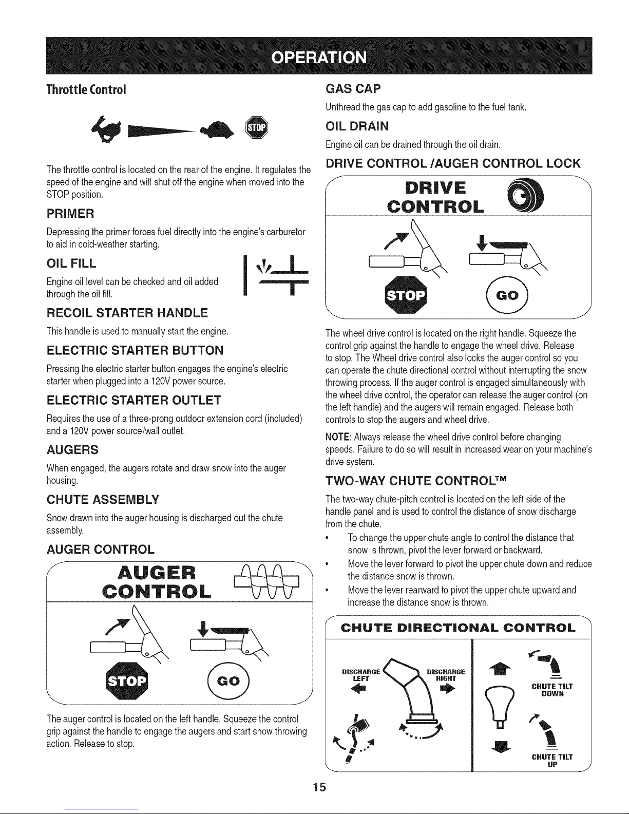
Nowthat youhavesetupyoursnowthrower,it'simportanttobecome
acquaintedwith itscontrolsandfeatures.RefertoFigure16.
SPEED SELECTOR SHIFT LEVER
Thespeedselectorshiftleveris locatedontherightside
ofthe handlepanel.Placethespeedselectorshiftlever
intoany ofeightpositionstocontrolthedirectionoftravel
andgroundspeed.
Forward
Yoursnowthrowerhassixforward(F) speeds.Position
one(1)isthe slowestand positionsix(6) isthefastest.
Reverse
Yoursnowthrowerhastwo reverse(R)speeds.One(1)is
theslowerandtwo (2) isthefaster.
6
5
4
3
t 2
F1
R1
Chute
Directional
Control
Oil Filler
Cap/Dipstick
PrimerKey
Throttle
OilDrain
Figure16
CHOKE CONTROL
Thechokecontrolisfoundon therearofthe
engineand isactivatedbyrotatingtheknob
counter-clockwise.Activatingthechokecontrol
closesthe chokeplateon thecarburetorandaids
in startingtheengine.
KEY
Thekeyis asafetydevice.It mustbefullyinserted
in orderfortheengineto start.Removethekey
whenthe snowthroweris notin use.
NOTE:Donotturnthekeyinan attempttostart
theengine.Doingsomaycauseit tobreak.
Electric
Start
Button
Electric
Starter Outlet
RecoilStarter
Handle
J
Meets ANSI Safety Standards
CraftsmanSnowThrowersconformto thesafetystandardoftheAmericanNationalStandardsInstitute(ANSI).
R2
14
Page 15
ThrottleControl
GAS CAP
Unthreadthe gascapto addgasolinetothefueltank.
OIL DRAIN
Engineoil canbedrainedthroughtheoildrain.
Thethrottlecontrolis locatedontherearoftheengine.It regulatesthe
speedof theengineandwillshutofftheenginewhenmovedintothe
STOPposition.
PRIMER
Depressingtheprimerforcesfuel directlyintotheengine'scarburetor
toaidin cold-weatherstarting.
Engineoil levelcanbecheckedandoiladded
OIL FILL I _Tp_._-
throughtheoilfill. |
RECOIL STARTER HANDLE
Thishandleisusedto manuallystarttheengine.
ELECTRIC STARTER BUTTON
Pressingtheelectricstarterbuttonengagestheengine'selectric
starterwhenpluggedintoa 120Vpowersource.
ELECTRIC STARTER OUTLET
Requirestheuseof athree-prongoutdoorextensioncord(included)
anda 120Vpowersource/walloutlet.
AUGERS
Whenengaged,theaugersrotateanddrawsnowintotheauger
housing.
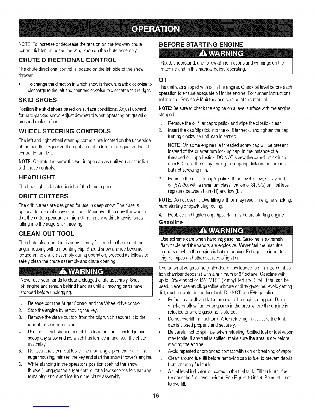
DRIVE CONTROL/AUGER CONTROL LOCK
f
DRIVE
CONTROL
Thewheeldrivecontrolis locatedonthe righthandle.Squeezethe
controlgrip againstthe handletoengagethe wheeldrive.Release
to stop.TheWheeldrivecontrolalsolockstheaugercontrolsoyou
canoperatethechutedirectionalcontrolwithoutinterruptingthe snow
throwingprocess.Iftheaugercontrolis engagedsimultaneouslywith
thewheeldrivecontrol,theoperatorcanreleasetheaugercontrol(on
theleft handle)andtheaugerswillremainengaged.Releaseboth
controlsto stoptheaugersandwheeldrive.
NOTE:Alwaysreleasethewheeldrivecontrolbeforechanging
speeds.Failuretodo sowillresultinincreasedwearonyourmachine's
drivesystem.
TWO-WAY CHUTE CONTROL TM
CHUTE ASSEMBLY
Snowdrawnintotheaugerhousingisdischargedout thechute
assembly.
AUGER CONTROL
f
AUGER
CONTROL
Theaugercontrolis locatedontheleft handle.Squeezethecontrol
gripagainstthehandleto engagetheaugersandstartsnowthrowing
action.Releasetostop.
Thetwo-waychute-pitchcontrolislocatedonthe left sideofthe
handlepanelandisusedto controlthedistanceofsnowdischarge
fromthechute.
• Tochangetheupperchuteangletocontrolthedistancethat
snowisthrown,pivottheleverforwardor backward.
• Movetheleverforwardtopivotthe upperchutedownand reduce
thedistancesnowisthrown.
• Movethelever rearwardtopivotthe upperchuteupwardand
increasethedistancesnowisthrown.
CHUTE DiRECTiONAL CONTROL
DISCHARGE _ DISCHARGE
CHUTE TiLT
DOWN
!
CHUTE TiLT
UP
15
J
Page 16
NOTE:Toincreaseordecreasethetensiononthe two-waychute
control,tightenorloosenthewing knobonthechuteassembly.
BEFORE STARTING ENGINE
CHUTE DIRECTIONAL CONTROL
Thechutedirectionalcontrolislocatedon theleftsideof thesnow
thrower.
• Tochangethedirectioninwhichsnowis thrown,crankclockwiseto
dischargeto theleftandcounterclockwisetodischargetotheright.
SKID SHOES
Positiontheskidshoesbasedon surfaceconditions.Adjustupward
forhard-packedsnow.Adjustdownwardwhenoperatingongravelor
crushedrocksurfaces.
WHEEL STEERING CONTROLS
Theleftandrightwheelsteeringcontrolsarelocatedonthe underside
ofthe handles.Squeezetherightcontroltoturn right;squeezethe left
controltoturn left.
NOTE:Operatethesnowthrowerinopenareasuntilyou arefamiliar
withthesecontrols.
HEADLIGHT
Theheadlightislocatedinsideofthe handlepanel.
DRIFT CUTTERS
Thedrift cuttersaredesignedforuseindeepsnow.Theiruseis
optionalfornormalsnowconditions.Maneuverthesnowthrowerso
thatthecutterspenetrateahighstandingsnowdrifttoassistsnow
fallingintotheaugersforthrowing.
Read,understand,andfollowall instructionsand warningsonthe
machineandinthis manualbeforeoperating.
Oil
Theunitwasshippedwithoilin theengine.Checkoillevelbeforeeach
operationtoensureadequateoil inthe engine.Forfurtherinstructions,
refertotheService& Maintenancesectionofthis manual.
NOTE:Besuretochecktheengineona levelsurfacewiththeengine
stopped.
1. Removetheoilfillercap/dipstickandwipethedipstickclean.
2. Insertthecap/dipstickintotheoil fillerneck,andtightenthecap
turningclockwiseuntilcap isseated.
NOTE:Onsomeengines,athreadedscrewcapwillbe present
insteadofthe quarterturnlockingcap.Intheinstanceofa
threadedoilcap/dipstick,DONOTscrewthecap/dipstickinto
check.Checktheoil byrestingthecap/dipstickonthethreads,
butnot screwingitin.
.
Removetheoilfiller cap/dipstick.Ifthelevelis low,slowlyadd
oil (5W-30,witha minimumclassificationofSF/SG)untiloil level
registersbetweenhigh(H)andlow (L).
NOTE:Donotoverfill.Overfillingwithoil mayresultinenginesmoking,
hardstartingor sparkplugfouling.
4. Replaceandtightencap/dipstickfirmlybeforestartingengine
Gasoline
CLEAN-OUT TOOL
Thechuteclean-outtoolisconvenientlyfastenedtotherearof the
augerhousingwitha mountingclip.Shouldsnowandicebecome
lodgedin thechuteassemblyduringoperation,proceedasfollowsto
safelycleanthechuteassemblyandchuteopening:
Neveruseyourhandsto cleara cloggedchuteassembly.Shut
offengineand remainbehindhandlesuntil all movingpartshave
stoppedbeforeunclogging.
1. Releaseboththe AugerControlandtheWheeldrivecontrol.
2. Stopthe enginebyremovingthekey.
3. Removetheclean-outtoolfromtheclipwhichsecuresit tothe
rearofthe augerhousing.
4. Usetheshovel-shapedendoftheclean-outtooltodislodgeand
scoopanysnowandicewhichhasformedinandnearthechute
assembly.
5. Refastentheclean-outtooltothemountingclipontherearof the
augerhousing,reinsertthe keyandstartthesnowthrower'sengine.
6. Whilestandinginthe operator'sposition(behindthesnow
thrower),engagetheaugercontrolfora fewsecondstoclearany
remainingsnowandice fromthechuteassembly.
Useextremecarewhenhandlinggasoline.Gasolineis extremely
flammableandthevaporsare explosive.Neverfuelthemachine
indoorsorwhiletheengineis hotor running.Extinguishcigarettes,
cigars,pipesandothersourcesof ignition.
Useautomotivegasoline(unleadedor lowleadedto minimizecombus-
tionchamberdeposits)witha minimumof87 octane.Gasolinewith
up to 10%ethanolor15%MTBE(MethylTertiaryButylEther)canbe
used.Neverusean oil/gasolinemixtureordirtygasoline.Avoidgetting
dirt, dust,or waterinthefueltank.DO NOTuseE85gasoline.
• Refuelina well-ventilatedareawiththeenginestopped.Donot
smokeorallowflamesor sparksintheareawheretheengineis
refueledor wheregasolineisstored.
• Donotoverfillthefueltank.After refueling,makesurethetank
capis closedproperlyandsecurely.
• Becarefulnotto spillfuel whenrefueling.Spilledfuelorfuelvapor
mayignite.Ifanyfuelis spilled,makesuretheareaisdrybefore
startingthe engine.
• Avoidrepeatedor prolongedcontactwithskinorbreathingofvapor
1. Cleanaroundfuelfillbeforeremovingcaptofueltopreventdebris
fromenteringfueltank..
2. A fuellevelindicatorislocatedinthe fueltank. Filltankuntilfuel
reachesthefuel levelindictor.SeeFigure10inset.Becarefulnot
tooverfill.
16
Page 17
STARTING THE ENGINE Recoil Starter
Alwayskeephandsandfeetclearofmovingparts.Donot usea
pressurizedstartingfluid.Vaporsareflammable.
NOTE:Allowtheengineto warmupfora fewminutesafterstarting.
Theenginewill notdevelopfullpoweruntilit reachesoperating
temperatures.
1. Makecertainboththe augercontrolandwheeldrivecontrolare in
thedisengaged(released)position.
2. Insertkeyintoslot.Makesureit snapsinto place.Donotattempt
toturnthekey.
NOTE:The enginecannotstartwithoutthekeyfullyinsertedintothe
ignitionswitch.
Electric Starter
Theoptionalelectricstarterisequippedwithagroundedthree-wire
powercordandplug,andis designedtooperateon 120voltAC
householdcurrent.Itmustbeusedwithaproperlygroundedthree-
prongreceptacleatalltimesto avoidthepossibilityof electricshock.
Followallinstructionscarefullypriortooperatingtheelectricstarter.
Determinethatyourhome'swiringisathree-wiregroundedsystem.
Aska licensedelectricianif youarenotcertain.
If youhaveagroundedthree-prongreceptacle,proceedasfollows:
1. Plugtheextensioncordinto theoutletlocatedonthe engine's
surface.Plugtheotherendofextensioncordintoathree-prong
120-volt,grounded,ACoutletin awell-ventilatedarea.
2. Movethrottlecontrolto FAST(rabbit)_ position.
3. Movechoketothe CHOKEpositionI,._1 (coldenginestart).
NOTE:Ifthe engineisalreadywarm,placechokecontrolinthe
RUNpositioninsteadof CHOKEIJl position.
4. Pushprimerthreetimes(3x),makingsureto coverventholein
primerbulbwhen pushing.If engineis warm,pushprimeronly
once.Alwayscoverventholewhenpushing.Coolweathermay
requireprimingtobe repeated.
5. Pushstarterbuttontostart engine.Oncetheenginestarts,im-
mediatelyreleasestarterbutton.Electricstarterisequippedwith
thermaloverloadprotection;systemwilltemporarilyshut-downto
allowstartertocool ifelectricstarterbecomesoverloaded.
Toprolongstarterlife,useshortstartingcycles(5 secondsmaximum
thenwaitoneminute).
6. Astheenginewarms,slowlyrotatethe chokecontroltothe RUN
position.Ifthe enginefalters,restartengineandrunwithchoke
athalf-chokepositionfora shortperiodoftime,andthenslowly
rotatethechokeintothe RUNposition.
7. Afterengineisrunning,disconnectpowercordfromelectric
starter.Whendisconnecting,alwaysunplugtheendatthewall
outletbeforeunpluggingtheoppositeendfromtheengine.
Donot pullthestarterhandlewhile theenginerunning.
1. Movethrottlecontrolto FAST(rabbit)_ position.
2. MovechoketotheCHOKEIJl position'_'(coldenginestart).If
engineiswarm,placechokeinthe RUNposition.
3. Pushprimerthreetimes,makingsuretocoverventholewhen
pushing.If engineiswarm,pushprimeronlyonce.Alwayscover
ventholewhenpushing.Coolweathermayrequireprimingto be
repeated.
4. Pullgentlyonthestarterhandleuntilit beginsto resist,thenpull
quicklyandforcefullytoovercomethecompression.Engineshould
start.Donot releasethehandleandallowitto snapback.Return
ropeSLOWLYtooriginalposition.Ifrequired,repeatthisstep.
5. Astheenginewarms,slowlyrotatethe chokecontroltotheRUN
position.Ifthe enginefalters,restartengineand runwithchoke
at half-chokepositionfora shortperiodoftime,andthenslowly
rotatethechokeintotheRUNposition.
Toavoidunsupervisedengineoperation,neverleavethemachine
unattendedwiththeenginerunning.Turntheengineoffafteruseand
removekey.
STOPPING THE ENGINE
Afteryouhavefinishedsnow-throwing,runenginefora fewminutes
beforestoppingto helpdry off anymoistureon the engine.
1. Movethrottlecontrolto STOPI_ position.
inc. Backfireoren( occur.
2. Removethekey.Removingthekeywillreducethepossibilityof
unauthorizedstartingoftheenginewhileequipmentisnotinuse.
Keepthekeyinasafeplace.Theenginecannotstartwithoutthekey.
3. Wipeallsnowandmoisturefromtheareaaroundtheengineas
wellas theareain andaroundthewheeldrivecontrolandauger
control.Also,engageand releasebothcontrolsseveraltimes.
TO ENGAGE WHEEL DRIVE
1. Withthethrottlecontrolinthe Fast(rabbit)_ position,move
speedselector leverintooneofthesixforward(F)positionsor
two reverse(R) positions.Selecta speedappropriatefor the
snowconditionsanda paceyou'recomfortablewith.
NOTE: WhenselectingaDriveSpeed,usetheslowerspeeds
untilyouarecomfortableandfamiliarwiththeoperationofthe
snowthrower.
2. Squeezethe drivecontrolagainstthehandleandthesnow
throwerwillmove.Releaseitanddrive motionwill stop.
NOTE:NEVERrepositionthespeedselectorlever(changespeedsor
directionoftravel)withoutfirstreleasingthedrivecontrolandbringing
thesnowthrowertoa completestop.Doingsowillresultin premature
wearto thesnowthrower'sdrivesystem.
17
Page 18
TO ENGAGE AUGER
1. Toengagetheaugerandstartthrowingsnow,squeezetheauger
controlagainstthelefthandle.Releaseto stoptheaugers.
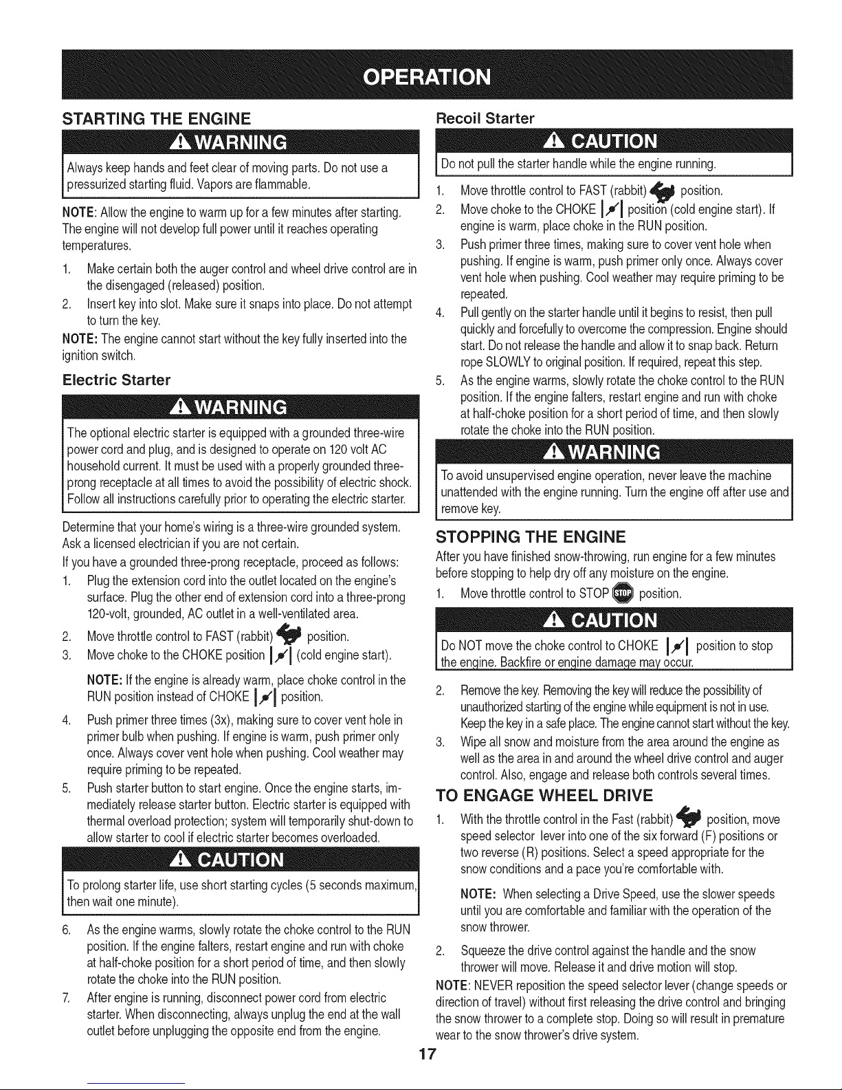
REPLACING SHEAR PINS
Theaugersaresecuredtothe spiralshaftwithshearpinsandbow-tie
cotterpins.Ifthe augershouldstrikeaforeignobjector icejam,the
snowthrowerisdesignedsothatthe pinsmayshear.If theaugerswill
notturn,checkto seeifthepinshavesheared.SeeFigure17.
NOTE:Twoextrashearpinsare suppliedinthemanualbag.
NEVERreplacetheaugershearpinswithanythingotherthanOEM
PartNo.738-04155replacementshearpins.Anydamagetothe
Iaugergearboxor othercomponentsas,a resultoffailingtodo sowill
[NOTbe coveredbyyoursnowthrowerswarranty.
Alwaysturnoff thesnowthrower'sengineand removethekeypriorto
replacingshearpins.
f-
Figure17
18
Page 19
MAINTENANCE SCHEDULE
Beforeperforminganytypeofmaintenance/service,disengageall
controlsandstoptheengine.Waituntilallmovingpartshavecometo a
completestop.Removethekeytopreventunintendedstarting.Always
wearsafetyglassesduringoperationorwhileperforminganyadjustments
orrepairs.
EachUse
1st5 -8hours
25 hours
50 hours
Annuallyor100hours
1. Engineoillevel
2. Looseormissinghardware
3. Unitandengine.
1. Engineoil
1. Engineoi11-
2. Controllinkagesand pivots
1. Engineoil
1. Sparkplug
1. Check
2. Tightenor replace
3. Clean
1. Change
1. Change
2. Lubewithlightoil
1. Change
1. Cleanandre-gap,orelse replace
withnewplug.
BeforeStorage 1. Fuelsystem
1. Runengineuntilit stopsfromlackof
fueloradda gasolineadditivetothe
gasin thetank.
Underheavyloador inhightemperatures
Followthemaintenanceschedulegivenbelow.Thischartdescribes
serviceguidelinesonly.UsetheServiceLogcolumnto keeptrackof
completedmaintenancetasks.Tolocate the nearest SearsService
Centeror to scheduleservice,simplycontactSearsat
1-800-4-MY-HOME®.
= =
ENGINE MAINTENANCE
Checking Engine Oil
Beforelubricating,repairing,orinspecting,disengageallcontrolsand
stopengine.Waituntilallmovingpartshavecometoa completestop.
Removethekeytopreventunintendedfiringoftheengine.
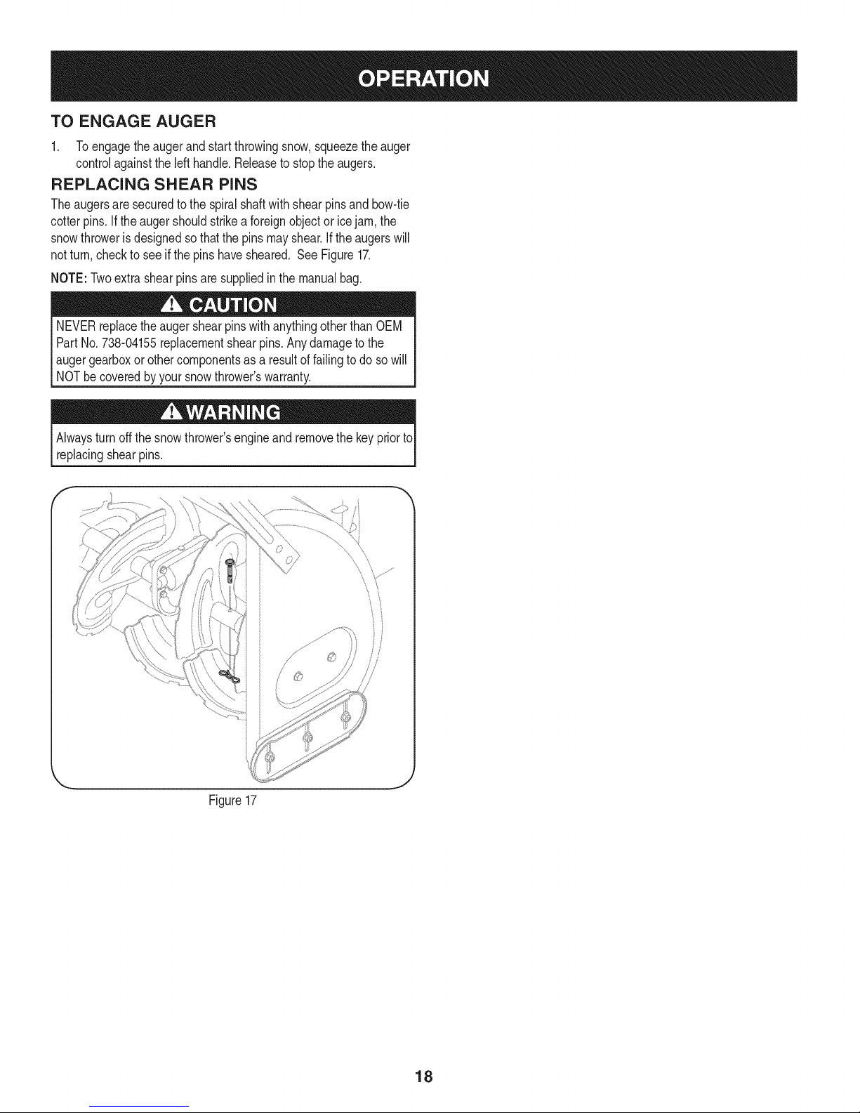
NOTE: Checktheoil levelbeforeeachuseto besurecorrectoil level
ismaintained.
Whenaddingoilto theengine,refertoviscositychart below.Engineoil
capacityisapproximately37 ounces.Donotover-fill.Usea 4-stroke,
oran equivalenthighdetergent,premiumqualitymotoroilcertified
tomeetorexceedU.S.automobilemanufacturer'srequirementsfor
serviceclassificationSG,SRMotoroilsclassifiedSG, SFwill show
thisdesignationonthecontainer.
1. Removetheoilfillercap/dipstickandwipethedipstickclean.
2. Insertthe cap/dipstickintotheoil fillerneck,butdo not screwitin.
NOTE:On someengines,athreadedscrewcapwillbepresent
insteadofthequarterturn lockingcap.Intheinstanceof a threadedoil
cap/dipstick,DONOTscrewthecap/dipstickin tocheck.Checktheoil
byrestingthe cap/dipstickonthe threads,butnotscrewingitin.
3. Removetheoilfillercap/dipstick,iflevelislow,slowlyaddoiluntil
oil levelregistersbetweenhigh(H) andlow(L). SeeFigure18.
4. Replaceandtightencap/dipstickfirmlybeforestartingengine.
J
Figure18
Changing Engine Oil
NOTE:Changetheengineoil afterthefirst5 hoursofoperationand
oncea seasonorevery50 hoursthereafter.
1. Drainfuelfromtankbyrunningengineuntilthefuel tankisempty.
Besurefuel fillcapis secure.
2. Placesuitableoilcollectioncontainerunderoil drainplug.
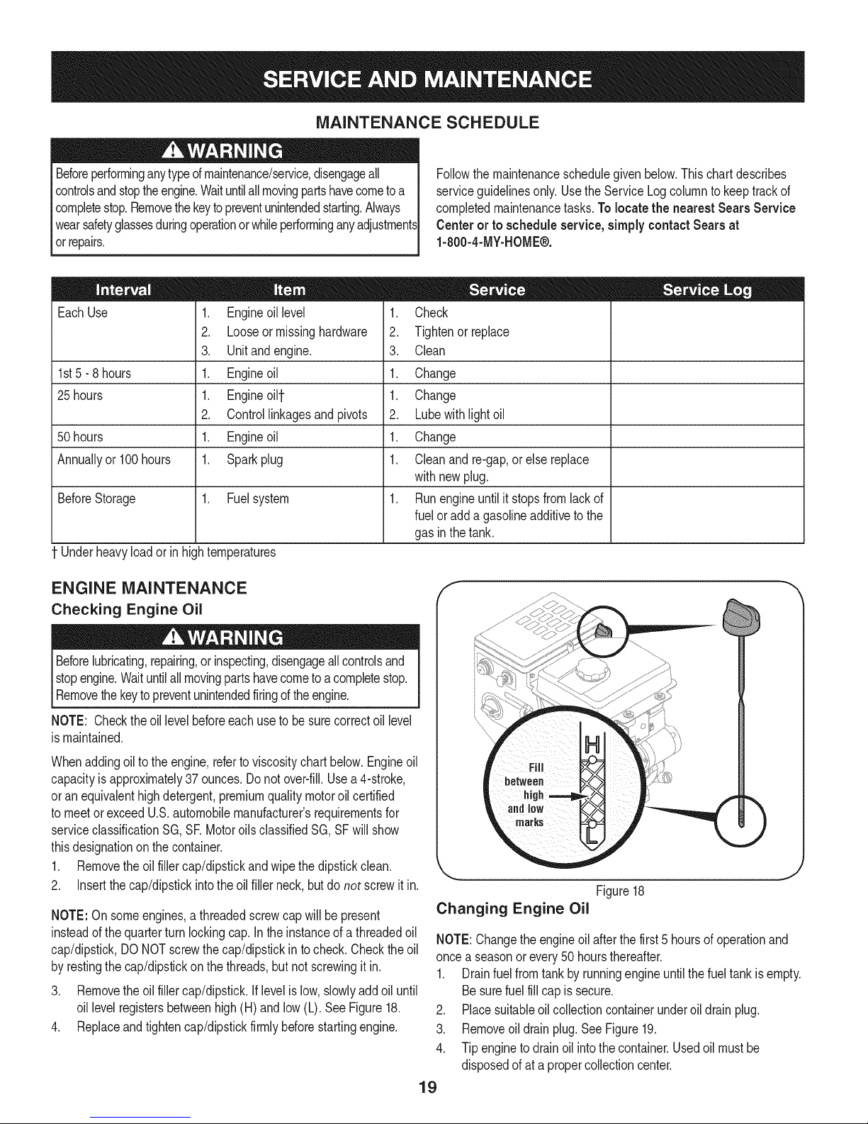
3. Removeoil drainplug.SeeFigure19.
4. Tipenginetodrainoil intothe container.Usedoil mustbe
disposedofat apropercollectioncenter.
19
Page 20
f
Oil Drain
Plug
Figure19
Usedoil isa hazardouswasteproduct.Disposeof usedoil properly.
Donotdiscardwith householdwaste.Checkwithyourlocalauthori-
tiesor SearsServiceCenterforsafedisposal/recyclingfacilities.
ifthe enginehasbeenrunning,themufflerwillbeveryhot.Becareful
notto touchthemuffler.
NOTE: Checkthesparkplugonceaseasonor every25 hoursof
operation.Changethe sparkplugoncea seasonorevery100hours.
Toensureproperengineoperation,the sparkplugmustbeproperly
gappedandfreeof deposits.
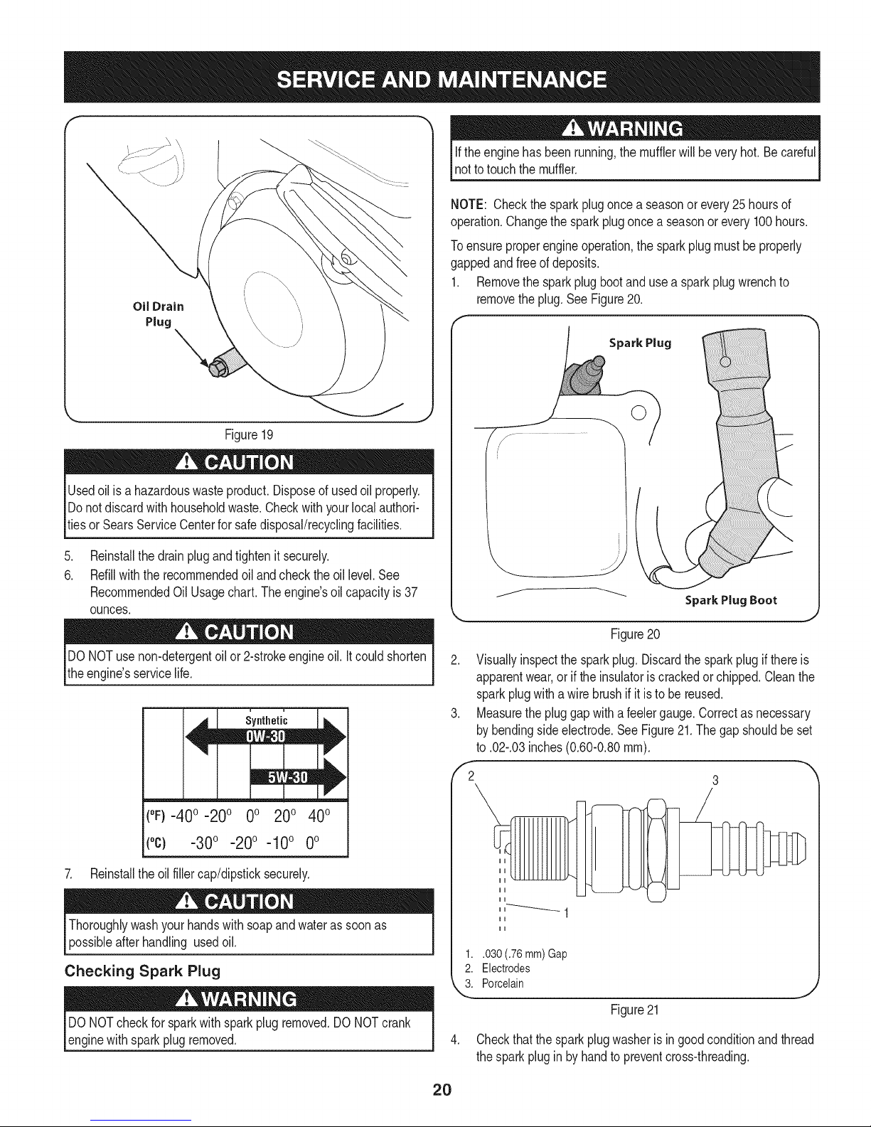
1. Removethesparkplugbootand usea sparkplugwrenchto
removetheplug.SeeFigure20.
Spark Plug
.
Reinstallthedrainplugandtightenit securely.
6.
Refillwiththerecommendedoil andchecktheoil level.See
RecommendedOil Usage chart. The engine's oilcapacity is 37
ounces.
DONOTuse non-detergentoilor 2-strokeengineoil.Itcouldshorten
theengine'sservicelife.
(°F}=40o =20o 0o 200 400
(°c) -30° -20° -10° 0°
7. Reinstalltheoilfillercap/dipsticksecurely.
Thoroughlywashyourhandswithsoapandwateras soonas
possibleafterhandling usedoil.
Checking Spark Plug
DONOTcheckforsparkwithsparkplugremoved.DONOTcrank
enginewithsparkplugremoved.
Figure20
2. Visuallyinspectthe sparkplug.Discardthe sparkplugif thereis
apparentwear,orif theinsulatoriscrackedorchipped.Cleanthe
sparkplugwithawirebrushifit isto be reused.
3. Measurethepluggapwitha feelergauge.Correctasnecessary
bybendingsideelectrode.SeeFigure21.Thegapshouldbe set
to .02-.03inches(0.60-0.80ram).
,'2 3
1..030 (.76 mm) Gap
2. Electrodes
k"_i Porcelain
Figure21
4. Checkthatthesparkplugwasheris ingoodconditionandthread
thesparkpluginby handtopreventcross-threading.
2O
Page 21
5. Afterthe sparkplugis seated,tightenwitha sparkplugwrenchto
compressthewasher.
NOTE:Wheninstallinga newsparkplug,tighten1/2-turnafterthe
sparkplugseatsto compressthe washer.Whenreinstallinga used
sparkplug,tighten1/8-to 1/4-turnafterthesparkplugseatsto
compressthewasher.
hotandcan ine.
CARBURETOR ADJUSTMENT
Thecarburetoris notuseradjustable.ContactSearsParts&Repairfor
adjustment.
LUBRICATION
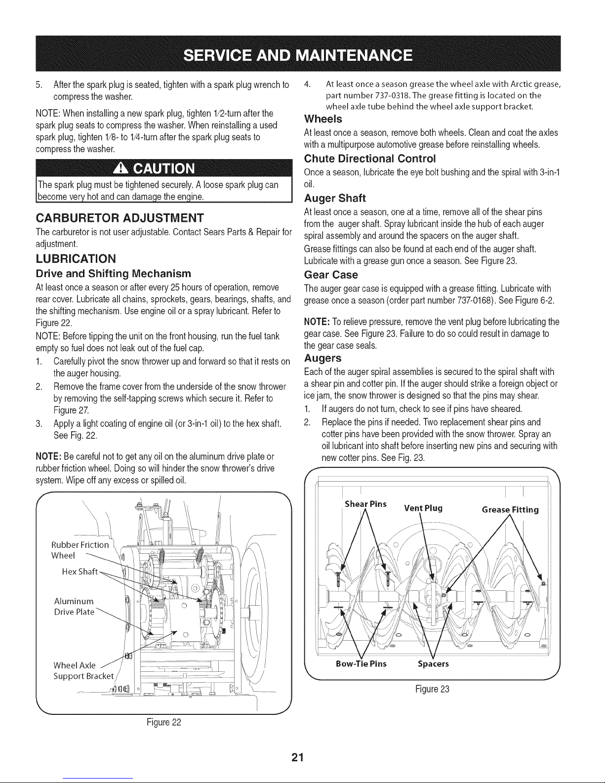
Drive and Shifting Mechanism
Atleastoncea seasonor afterevery25 hoursofoperation,remove
rearcover.Lubricateall chains,sprockets,gears,bearings,shafts,and
theshiftingmechanism.Useengineoilora spraylubricant.Referto
Figure22.
NOTE:Beforetippingtheunitonthe fronthousing,runthefueltank
emptyso fueldoesnotleakoutof thefuelcap.
1. Carefullypivotthesnowthrowerupandforwardsothat it restson
theaugerhousing.
2. Removetheframecoverfromtheundersideof thesnowthrower
byremovingtheself-tappingscrewswhichsecureit. Referto
Figure27.
3. Applya lightcoatingofengineoil (or3-in-1oil) tothehexshaft.
SeeFig.22.
NOTE:Becarefulnottoget anyoilon thealuminumdrive plateor
rubberfrictionwheel.Doingsowill hinderthesnowthrower'sdrive
system.Wipeoff anyexcessorspilledoil.
4. At least once a season grease the wheel axle with Arctic grease,
part number 737-0318. The grease fitting is located on the
wheel axle tube behind the wheel axle support bracket.
Wheels
At leastonceaseason,removebothwheels.Cleanandcoattheaxles
witha multipurposeautomotivegreasebeforereinstallingwheels.
Chute Directional Control
Onceaseason,lubricatetheeyeboltbushingandthespiralwith3-in-1
oil.
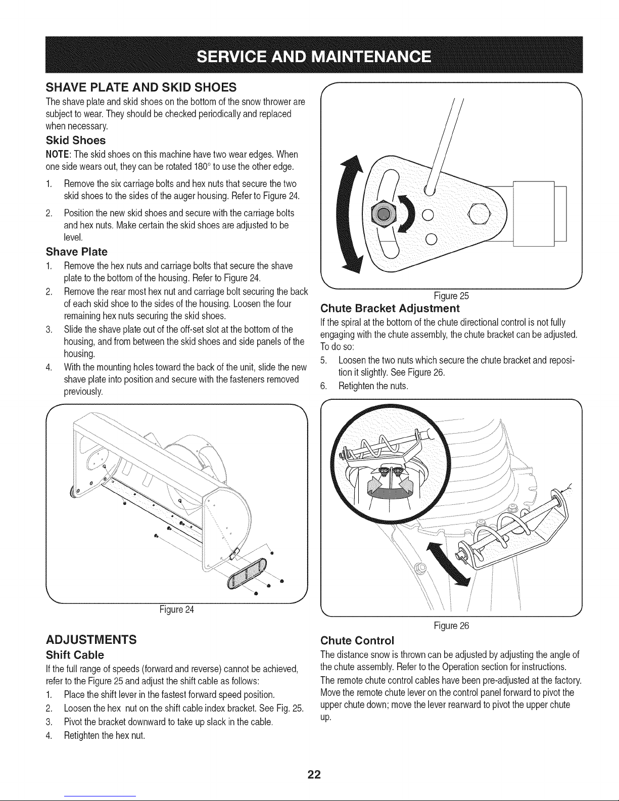
Auger Shaft
At leastonceaseason,oneatatime, removeallof theshearpins
fromthe augershaft.Spraylubricantinsidethehubofeachauger
spiralassemblyandaroundthe spacersontheaugershaft.
Greasefittingscan alsobe foundateachendof theaugershaft.
Lubricatewitha greasegunoncea season.SeeFigure23.
Gear Case
Theaugergearcaseis equippedwitha greasefitting.Lubricatewith
greaseoncea season(orderpartnumber737-0168).SeeFigure6-2.
NOTE:Torelievepressure,removetheventplugbeforelubricatingthe
gearcase.See Figure23. Failuretodosocould resultindamageto
thegearcaseseals.
Augers
Eachoftheaugerspiralassembliesissecuredtothe spiralshaftwith
a shearpinandcotterpin.If theaugershouldstrikeaforeignobjector
icejam,the snowthrowerisdesignedsothatthepinsmayshear.
1. Ifaugersdonot turn,checkto seeif pinshavesheared.
2. Replacethepinsif needed.Tworeplacementshearpinsand
cotterpins havebeenprovidedwiththe snowthrower.Sprayan
oil lubricantintoshaftbeforeinsertingnewpinsand securingwith
newcotter pins.SeeFig.23.
i • i I ii
i Shear Pins ii:i
" Vent Plug Grease Fitting
Aluminum
Drive
Wheel Axle
Support Bracket
Figure22
/ .............
Bow=Tie Pins Spacers
Figure23
21
Page 22
SHAVE PLATE AND SKiD SHOES
Theshaveplateand skidshoesonthebottomofthesnowthrowerare
subjectto wear.Theyshouldbecheckedperiodicallyandreplaced
whennecessary.
Skid Shoes
NOTE:Theskidshoesonthismachinehavetwowearedges.When
onesidewearsout, theycanberotated1800to usetheotheredge.
1. Removethesix carriageboltsandhexnutsthatsecurethetwo
skidshoestothe sidesoftheaugerhousing.RefertoFigure24.
2. Positionthenew skidshoesandsecurewiththecarriagebolts
andhexnuts.Makecertaintheskidshoesare adjustedtobe
level.
Shave Plate
1. Removethehexnutsandcarriageboltsthatsecuretheshave
plateto thebottomofthehousing.Referto Figure24.
2. Removetherearmosthexnutand carriageboltsecuringtheback
ofeachskidshoeto thesidesofthehousing.Loosenthefour
remaininghexnutssecuringtheskidshoes.
3. Slidetheshaveplateoutof theoff-setslotat thebottomofthe
housing,andfrombetweentheskidshoesandsidepanelsofthe
housing.
4. Withthemountingholestowardthebackof theunit,slidethenew
shaveplateinto positionandsecurewiththe fastenersremoved
previously.
f
k
J
Figure25
Chute Bracket Adjustment
Ifthespiralatthe bottomofthechutedirectionalcontrolis notfully
engagingwiththechuteassembly,thechutebracketcanbeadjusted.
Todo so:
5. Loosenthetwo nutswhichsecurethechutebracketandreposi-
tionit slightly.SeeFigure26.
6. Retightenthenuts.
Figure24
ADJUSTMENTS
Shift Cable
If thefull rangeofspeeds(forwardandreverse)cannotbeachieved,
referto theFigure25andadjusttheshiftcableasfollows:
1. Placetheshiftleverin thefastestforwardspeedposition.
2. Loosenthehex nuton theshiftcableindexbracket.SeeFig.25.
3. Pivotthebracketdownwardtotakeupslack inthecable.
4. Retightenthehexnut.
0
Figure26
Chute Control
Thedistancesnowisthrowncanbe adjustedbyadjustingtheangleof
thechuteassembly.Refertothe Operationsectionforinstructions.
Theremotechutecontrolcableshavebeenpre-adjustedat thefactory.
Movethe remotechuteleveronthecontrolpanelforwardtopivotthe
upperchutedown;movetheleverrearwardtopivottheupperchute
up.
22
Page 23

Wheel drive control
Refertothe Adjustmentsectionofthe Assemblyinstructionsto adjust
thewheeldrivecontrol.Tofurtherchecktheadjustment,proceedas
follows:
1. Withthe snowthrowertippedforward(be certainto runthe
fueltankdry beforetippingtheunitforward),removetheframe
coverunderneaththesnowthrowerbyremovingtheself-tapping
screws.SeeFig.27.
J
Figure27
Auger Control
RefertotheAssemblysectionforinstructionson adjustingtheauger
controlcable.
Skid Shoes
RefertotheAssemblysectionforinstructionson adjustingtheskid
shoes.
Tire Pressure
RefertotheAssemblysectionforinstructionson adjustingthetire
pressure.
BELT REPLACEMENT
Belt Removal Preparation
1. Removethechutecrankrodfromthechutecrankassemblyby
removingthe hairpinclip shownin Fig.29.Movethechutecrank
rodawayfromtheassemblyas shown.
Removethreeself-tapscrewson bothsidesof thetransmission
housingas showninFig.29.
2. Locatetheopeningbetweentheaxlesupportbracketand
thefrontframesupport(SeeFigure28). Lookingthroughthis
opening,withthe wheeldrivecontrolreleased,theremustbe
clearancebetweenthefrictionwheelandthe driveplateinall
positionsofthespeedselectorlever.
3. Withthewheeldrivecontrolengaged,thefrictionwheelmust
contactthedrive plate.SeeFigure28.
Drive -Axle Supp.
Plate Bracket
Opening
Figure29
3. Removethe plasticbeltcover,locatedneartheengine,by remov-
ing thethreeself-tappingscrewsthatsecureit.See Figure30.
f
Figure28
4. Ifthereisnofrictionwheelclearance,or thefrictionwheeldoes
notsolidlycontactthe driveplate,re-adjustthelocknuton the
lowerendof thedrivecablefollowingtheinstructionsinthe
Assemblysection.
5. Reassembletheframecover.
23
Page 24

.
Loosentheboltshownin Figure31securingthebeltkeeper
bracketandremovetheotherbolt.Pushthebelt keeperand
bracketupoff theenginepulley.
Loosen
\
\
Figure31
Auger Belt Replacement
1. Removethebow-tieclipandflatwasherfromtheferrulein order
todisconnecttheaugeridlerrodfromthebrakebracketassem-
bly.SeeFigure32.
NOTE:Makesurethatthelocationof theferruleontheauger
idlerrodismaintained.
HairpinClip
Ferrule
AugerIdlerRod
z-fitting
J
Figure33
Placeablockof woodunderneaththeaugerhousingasshownin
Figure34 andseparateaugerhousingfromtheframebytiltingthe
housingforwardandpullingupthehandles.
Figure34
6. Blocktheimpellerwithapieceofwoodtopreventitfromspinning
andusea 1/2"wrenchtoremovethehexscrewandflatwasher
fromthecenterofthepulleyontheaugerhousing.SeeAinFig.35.
7. Liftthebrakebracketassemblyoutofthe pulleygroove(B in
Figure35)andslide thepulleyassemblyoff the postsoftheauger
pulleyadapter(C)to removethe oldbelt.
Figure32
2. Sliptheaugercontrolbelt (thefrontbelt) offtheenginepulley.
3. Pullthebrakebracketassemblytowardsthecableguideroller
andunhooktheaugercablez-fitting.SeeFigure33.
4. Frombothsidesof thethe frameassembly,usea 1/2"wrenchto
removethethreehextap screwssecuringthe frametothe auger
housingassembly.Referbackto Figure29.
NOTE:Do notremovethelowerhexflangelocknutoneachside.
24
NOTE:Thepulleyadaptermayslideoff theaugerinputshaft
whenremovingthepulley.Useextracautionto ensurethe
adapterdoesfalland/or getdamagedwhen removingthepulley.
.
Placethenewaugerbeltin theV-grooveof theaugerpulleyand
placethepulleyw/belt insidethebeltkeepers.
9.
Turnthepulleyasnecessaryto alignitsthreeslotsapproximately
withthepostsofthepulleyadapter,thenpivotthe brakebracket
assemblyawayfromthepulleygroove. Whilealigningthepulley
slotsandadapterposts,pushtheaugerpulleyfullyontothe
adapter.RefertoFigure35.Ensurethebrakepuckofthebrake
bracketassemblyalignsandisfullyseatedin thepulleygroove.
Page 25

Brake
!
pterPost
%
J
Figure35
NOTE: If thepulleyadapterwasremovedwiththepulley,alignthe
splinesofthe pulleyadapterandaugerinputshaft,andpushthepulley
andadapterontotheinputshaft.Referto Figure35.
10. Slidethe washerontothe hexscrewremovedearlierandapply
Loctite262to thethreadsof thehexscrew.
11. Insertthehexscrewthroughthepulleyassemblyandintothe
threadsofthe inputshaft.Torquethehexscrewto250-325in.
Ibs.to securetheaugerpulleyassemblyon the inputshaft.
12. Ifalso replacingthedrivebelt,proceedtothe "DriveBelt"instruc-
tions.If not,repositionthetransmissionframebackonto
theaugerhousing.
13. Installthedrive belton theenginepulley,re-connecttheauger
cablez-fittingandaugeridler rodferruletothebrakebracket.
Repositionand securetheenginepulleybeltguard,and re-install
thebeltcover.
NOTE:Makesureto removethepieceofwoodblockingtheimpeller.
Checktheaugerdrivebeltadjustment.Withthe augerclutchlever
inthedisengagedposition,thetopsurfaceofthenewbeltshouldbe
evenwiththeoutsidediameterofthe pulley.
Toadjust,disconnectferrulefrombrakebracketassembly.Thread
ferrulein(towardsidler)toincreasetensiononbelt,orout todecrease
belttension.
J
Figure36
2. Rollthedrivebeltoff thelowerdrivepulley.
3. Removethe beltfromtheenginepulley.
4. Installthe newbelton thepulleysinthe reverseorderand
re-tensionwiththeidlerpulley.
5. Reassemblebyperformingthepreviousstepsintheopposite
orderand mannerofremoval.
CHANGING FRICTION WHEEL
Therubberonthe frictionwheelissubjecttowearandshouldbe
checkedperiodically.Replacethefrictionwheelif anysignsofwearor
crackingarefound.
1. Runthe unit'sfueltankdry beforeperformingStep2. Donot
attempttopourfuel fromtheengine.
2. Tipthesnowthrowerupand forward,sothat it restsonthe
housing.
3. Removescrewsfromtheframecoverunderneaththesnow
thrower(referto Figure37).Removetherightwheelfromtheaxle.
NOTE:Thebrakepuckmustalwaysbefirmly seatedinthepulley
groovewhenaugercontrolisdisengaged.
IMPORTANT:Repeatthe"AugerDriveControlTest"fromthe As-
semblysectionbeforeoperatingsnowthrower.
Drive Belt Replacement
If notalreadydone,removetheaugerdrivebeltfromthefrontpulleyof
theenginedoublepulley.Referto "AugerBeltReplacement"instruc-
tionsintheprevioussub-section.
1. a.Pullthe idlerpulleyawayfromthe backsideofthedrivebeltto
relievethetension.SeeFigure36.
b.Slipthe drivebeltofftheidlerpulley. Carefullyreleasetheidler
pulley.
e
Figure37
25
Page 26

.
Usinga 3/4"wrench,holdthehexshaftandremovethehex
screwandbellevillewasherand bearingfromleft sideofthe
frame.Referto Figure38.
f
RemoveHexScrew
BellevilleWasher
l,
Figure38
.
Holdingthefrictionwheelassembly,slidethehexshaftoutof
thefrictionwheelassemblyandthe rightsideof theframe.The
spacerontheleft sideofthehexshaftwillfallandthe sprocket
shouldremainhanginglosein thechain.
.
Liftthefrictionwheelassemblyoutbetweentheaxle shaftand
thedriveshaftassemblies.
7.
Removefourscrewssecuringthefrictionwheelto thehub
assembly(referto Figure39).Discardoldfrictionwheel.
FrictionWheelAss'y.
/
SlideHex
ShaftOut
RightSide
f
!!Si¸i¸i¸;i!!¸i¸:¸¸i¸¸i¸!_¸¸_!¸¸i¸¸¸¸¸¸¸¸¸¸¸¸¸'¸¸¸"i!i_i_!!!i!i;i!iiiiii!iiiii
f
_,,, J
8. Reassemblethenewfrictionwheelontothehubassembly,
tighteningthefourscrewsin rotationandwithequalforce.It is
importanttoassemblethefrictionwheelsymmetricallyforproper
functioning.
9. Repositionthefrictionwheelassemblyin thesnowthrowerframe.
Insertthe pinfromthespeedselectorarmassemblyintothe
frictionwheelassemblyandholdassemblyin position.Referto
Figure40.
_L
¢,
Figure39
0
Figure40
10. Slidethe hexshaft throughtherightsideoftheframetowardthe
Idt sideandthroughthefrictionwheelassembly.
11. Aftermakingcertainthatthe chainisonboththelargeandthe
smallsprocket,alignthehexshaftwiththehexhubofthesmall
sprocket,andslidethe shaftthroughthesprocket.
NOTE:Ifthe sprocketfell fromthesnowthrowerwhileremoving
thehex shaft,placethesprocketonthechain.Realignthe
sprocketonthechainwiththehex hubfacingtherightsideof
unit.Positionthehexhubofthe sprockettowardthe frictionwheel
whenslidingthesprocketonto thehexshaft.
12. Slidethe spacerontothe endofthehexshaft.
Note:The spaceristobeplacedon thehexshaftbetweenthe
sprocketandbearingpreviouslyremovedonthe leftsideofthe
frame.
13. Alignthe bearingontherightendof thehexshaftwiththehole
intherightsideof theframe,thenpushthehexshafttotheleft
intopositioninthe frame.
14. Slidethe bearingontothe leftendofthehexshaftandpressinto
theholeon theleftsidetheframe.
15. Placethebellevillewasher(roundedsidetowardhead)ontothe
hexscrewremovedearlier,andinsertthescrewinto thethreaded
holeofthe hexshaft.
16. Graduallytightenthehexscrewto fullyseatthebearingsineach
sideof theframeandtosecurethehexshaft.
17. Positiontheframecoveron thebottomofthe frameandsecure
withtheself-tappingscrews.Pivotthe snowthrowerdownto it
normaloperatingposition.
iMPORTANT:Repeatthe drivecontroltestfromtheAssemblysection
ofthis manualbeforeoperatingthe snowthrower.
26
Page 27

Ifthesnowthrowerwillnotbeusedfor30daysorlonger,orifitistheendofthesnowseasonwhenthelastpossibilityofsnowisgone,the
equipmentneedstobestoredproperly.Followstorageinstructionsbelowtoensuretopperformancefromthesnowthrowerformanymoreyears.
PREPARING ENGINE
Enginesstoredover30daysneedtobedrainedoffueltoprevent
deteriorationandgumfromforminginfuelsystemor onessential
carburetorparts.If thegasolineinyourenginedeterioratesduring
storage,youmayneedto havethecarburetor,andotherfuelsystem
components,servicedorreplaced.
1. Removeall fuelfromtankbyrunningengineuntilit stops.Donot
attempttopourfuel fromtheengine.
2. Changetheengineoil.
3. Removesparkplugandpourapproximately1oz.(30 rnl)ofclean
engineoil intothecylinder.Pullthe recoilstarterseveraltimesto
distributetheoil,and reinstallthesparkplug.
4. Cleandebrisfromaroundengine,andunder,around,andbehind
muffler.Applya lightfilmofoilon anyareasthatare susceptible
torust.
• Storeina clean,dry andwellventilatedareaawayfromanyap-
pliancethatoperateswithaflameor pilotlight,suchasa furnace,
waterheater,or clothesdryer.Avoidanyareawitha spark
producingelectricmotor,or wherepowertoolsareoperated.
Neverstoresnowthrowerwithfuelintank indoorsorinpoorlyventi-
latedareas,wherefuelfumesmayreachanopenflame,sparkor pilol
lightas onafurnace,waterheater,clothesdryerorgasappliance.
PREPARING SNOW THROWER
Whenstoringthe snowthrowerinanunventilatedormetalstor-
age shed,careshouldbetakentorustprooftheequipment.Using
a lightoilor silicone,coattheequipment,especiallyanychains,
springs,bearingsandcables.
• Removealldirt fromexteriorofengineandequipment.
• Followlubricationrecommendations.
• Storeequipmentina clean,dryarea.
• Inflatethetirestothe maximumPSi.Referto tiresidewall.
• If possible,avoidstorageareaswithhighhumidity.
• Keeptheenginelevelin storage.Tiltingcancausefueloroil
leakage.
27
Page 28

Enginefailstostart
Enginerunningerratically/
inconsistentRPM(huntingor
surging)
Excessivevibration
Lossofpower
Unitfailstopropelitself
Unitfailstodischargesnow
1. ChokecontrolnotinCHOKEposition.
2. Sparkplugwire disconnected.
3. Faultysparkplug.
4. Fueltankemptyor stalefuel.
5. Enginenotprimed.
6. Keynot inserted.
7. Extensioncordnotconnected(when
usingelectricstartbutton,on modelsso
equipped).
1. EnginerunningonCHOKE.
2. Stalefuel.
3. Waterordirt infuel system.
4. Over-governedengine.
1. Loosepartsor damagedauger.
1. Sparkplugwire loose.
2. Gascap ventholeplugged.
1. Drivecableinneedof adjustment.
2. Drivebeltlooseor damaged.
3. Wornfrictionwheel.
1. Chuteassemblyclogged.
2. Foreignobjectlodgedin auger.
3. Augercablein needof adjustment.
4. Augerbeltlooseordamaged.
5. Shearpin(s)sheared.
1. Movechokecontrolto CHOKEposition.
2. Connectwireto sparkplug.
3. Clean,adjustgap,or replace.
4. Filltankwithclean,freshgasoline.
5. PrimeengineasinstructedintheOperationSection.
6. Insertkeyfully intotheswitch.
7. Connectoneendof theextensioncordto theelectric
starteroutletandthe otherendtoathree-prong
120-volt,grounded,ACoutlet.
1. Movechokecontrolto RUNposition.
2. Filltankwithclean,freshgasoline.
3. Drainfueltankby runningengineuntilitstops.Refill
withfreshfuel.
4. ContactyourSearsParts& RepairCenter.
1. Stopengineimmediatelyand disconnectsparkplug
wire.Tightenall boltsandnuts.Ifvibrationcontinues,
haveunit servicedbya SearsParts& RepairCenter.
1. Connectandtightensparkplugwire.
2. Removeiceand snowfromgascap. Becertainvent
holeisclear.
1. Adjustdrivecontrolcable.Referto Serviceand
Maintenancesection.
2. Replacedrivebelt.Referto Serviceand Mainte-
nancesection.
3. Havefrictionwheelreplacedata SearsParts&
RepairCenter.
1. Stopengineimmediatelyand disconnectsparkplug
wire.Cleanchuteassemblyandinsideofauger
housingwithclean-outtoolor astick.
2. Stopengineimmediatelyand disconnectsparkplug
wire.Removeobjectfromaugerwith clean-outtool
ora stick.
3. Adjustaugercontrolcable.RefertoAssembly
section.
4. Replaceaugerbelt.RefertoServiceand Mainte-
nancesection.
5. Replacewith newshearpin(s).
Chutefailstoeasilyrotate180 1. Disassemblechutecontroland reassembleas
1. Chuteassembledincorrectly.
degrees directedintheAssemblysection.
NEED HORE HELP?
Yot,Fttfind. th_ answer a!"@ mo_e on ma_age_y_ifeocom _ for free]
Find this and att your other product manua[s ontine.
Get answers from our team of home experts.
Get a personalized maintenance p[an for your home.
Find information and tools to he[p with home projects.
28
Page 29

Craftsman Snow Thrower Model 247.8839700
22
20
25
25 _18
17
69
19
48
10
4
42
J
60
66
29
Page 30

Craftsman Snow Thrower Model 247.883970
D = I 0
918-0281A Bracket Assy, Auger Brake
2. 684-0090B-0637 Impellar, 16"
3. 931-2643 Tool, Cleanout
4. 710-0376 Scr,Hex Cap, 5/16-18 x 1.00
5. 710-04484 Screw, 5/16-18 x .750
6. 710-0451 Screw, Carriage, 5/16-18 x .75
7. 710-04606A Screw, 5/16-18 x .4300
8. 710-1245B Screw, 5/16-24 x .875
9. 911-0677 Ferrule
10. 712-04063 Nut, Flnge Lk, 5/16-18
11. 712-04065 Nut, Fig Lk, 3/8-16
12. 914-0135 Key, Woodruff, I/4 x 3/4
13. 714-04040 Pin, Bowtie Cotter
14. 915-0118 Pin, Spirol, 5/16 x 1.75
15. 725-0157 Tie, Cable
16. 926-04012 Nut, Push
17. 731-1696B Adapter, Chute, 6"
18. 732-0858 Spring, Extension
19. 936-0159 Washer, .349 x .879 x .063
20. 736-0174 Washer, .625 x .885 x .015
21. 736-0505 Washer, Flat, .34 x 1.50 x .150
22. 936-3008 Washer, .344 x .75 x .12
23. 736-3046A Washer, 1.01 x 1.86 x .06
24. 731-2635 Clip, Mounting
25. 938-0281 Screw, Shoulder, .625 x .17
26. 738-04155 Pin, Shear, .25 x 1.75
27. 741-0192 Bearing, Flange w/Flats
28. 941-04024 Bearing, Self Aligning
29. 747-0980A Rod, Auger Idler
30. 748-04067A Pulley, Adapter, .75 Dia.
31. 950-04020 Spacer, 1.004 x 1.375 x .25
32. 756-04244A Pulley, Auger Drive, 10.0
33. 790-00264A-0637 Bracket, Gear Box Support
34. 05244B Housing, Bearing
35. 784-0315A-0637 Housing, Bearing
36. 918-04514 Gear Box Assembly, Auger
D = I! II
684-04151-4028 Spiral Assy, LH
38. 684-04152-4028 Spiral Assy, RH
39. 684-04214-0691 Housing, Auger - 33"
40. 731-05162 Spacer, 1.0 x 1.5 x 2
41. 731-05163 Spacer, 1.0 x 1.5 x 1
42. 938-04158 Axle, Spiral, 33"
43. 741-0494 Bushing, Flange, 1.051 x 1.16
44. 784-5714B-0637 Shave Plate
45. 710-3168 Bolt, Carriage, 3/8-16 x 1.0
46. 710-3034 Bolt, Carriage, 3/8-16 x 1.25
47. 731-06007 Shoe, Skid
48. 790-00181-0637 Drift Cutter
49. 929-0071A Extension Cord, 110V
50. 918-0246 Hsg Assy Auger RH (Inc. 65 & 66)
51. 918-0435 Hsg Assy Auger LH (Inc. 65 & 66)
52. 710-1260A Screw, LD, 5/16-18 x .750
53. 711-04714 Shf, Drive, Auger
54. 914-0126 Key, Hi Pro, 3/16 x 3/4
55. 716-0111 Ext, Ret, Ring
56. 917-0299 Gear, Worm, Dbl Thread
57. 917-1425 Gear, Worm, LH
58. 921-0145 Seal, Oil
59. 721-0325 Plug
60. 936-0266 Washer, Flat, 1.52 ID x 2.00D
61. 936-0291 Washer, Flat, .88 ID x .38 OD
62. 738-0275 Shf, Gear, Worm
63. 741-0184 Brg, Thrust
64. 941-0217 Sleeve
65. 921-0146 Oil Seal
66. 741-0670 Flange Bearing
67. 954-04194A V Belt,4L x 44.60 Lg.
68. 937-3000 Lube Fitting, 3/16 #70
69. 736-0188 Washer, Flat, .78 x 1.49 x .08
70. 720-0284 Wing Knob
71. 712-3007 Jam Nut, 5/16-18
72. 736-0262 Washer, Flat, .385 x .870
30
Page 31

Craftsman Snow Thrower Model 247.883970
65
57
66
_\ 7 58
5O
64
30
21
15
79
79
40
/
/
/
/
38
3 39
\
31
Page 32

m _ O O
684-04308A ChuteCrankAssembly
2 684-04350 JointBlockAssembly
3 710-0276
4 710-04682
5 710-0572
6 710-3118
7 712-04063
8 912-3010
9 914-0101
10 914-0104
Screw,Carriage,5/16-18x 1.0
Screw,Hex,3/8-16x 2.00Lock,Gr5
Screw,Carriage,5/16-18x2.5
Screw,Hex,3/8-16x 1.0Lock,Gr5
FlangeLockNut,5/16-18
HexNut,5/16-18
internalCotterPin
internalCotterPin
11 715-04095 SpringPin
12 720-0201A Knob,Crank
13 720-0284 Knob,WingNut, 5/16-18
14 926-0100 Cap,Push,3/8
15 735-0234 Grommet,Rubber
16 736-0105 Washer,Bel,.375x .87x .063
17 936-0159 Washer,Fiat,.349x .879.063
18 936-0185 JWasher,.375x.738x .063
19 736-0242 Washer,Belleville,.34x .872x .06
20 941-0475 PlasticBushing,.380I.D.
21 747-04747 _ EyeBolt
22 747-04925A-0637 ChuteRod
23 749-04675-0691 Handle,Upper- LH
24 749-04674-0691 Handle,Upper- RH
25 749-0991-0691 Handle,Lower
26 790-00329-0637 ChuteCrankBracket
27 716-04036 Ring,Retainer
28 725-0157 CableTie
29 731-06113 . Trigger
30 738-04126 Pin,3/16
31 710-04022 HexHeadScrew,MB1.25
32 732-04677 CableGuide
33 936-0264 FiatWasher,.330x .630x .0635
34 984-04230 J2-WayChuteControl Assy
TM
35 710-04187 Hi-LoScrew,1/4-15x 0.5
36 710-0458 Bolt,Carriage,5/16-18x 1.75
37 710-0597 Screw,1/4-20x 1.00
38 710-0895 Hi-LoScrew,1/4-15x .75
39 712-04064 FlangeLockNut,1/4-20
40 731-0846C UpperChute
41 731-0851A Chute,FlangeKeeper
D _ O
731-0903E LowerChute
43 731-1313C ChuteTiltCableGuide
44 936-0231 FiatWasher
45 784-5594-0637 CableBracket
46 631-04133A HandleClutchLock- LH
47 631-04134B HandleClutchLock- RH
48 931-04187A HandlePanel
49 646-0012 CableAssembly,Auger/Drive
746-0952 Cable,Clutch
732-0184 Spring,Extension
50 684-04111B HandleEngageAssy- LH
51 684-04112C HandleEngageAssy- RH
52 684-04250 RodAss'y,ClutchLockPivot
53 710-04326 Screw,#8-16x0.50
54 710-04586 Screw,1/4-20x 1.625
55 710-0837 ABScrew,#10-16
56 710-1233 Screw,#10-24x 0.375
57 710-3069 Screw,1/4-20x.375
58 712-04081A ShoulderNut,1/4-20
59 720-04039 ShiftKnob
60 736-0159 FiatWasher,.349x .879x .063
61 725-05148 WiringHarness(NotShown)
62 725-04393 Htd.HandGripon/off Switch
63 725-05239 LightSocket
64 725-05149 HeatedHandGrip
65 731-04894D LockPlate
66 731-04896B ClutchLockCam
67 732-0193 CompressionSpring
68 732-04219C ClutchLockSpring
69 732-04238 TorsionSpring
70 935-0199A RubberBumper
71 936-0267 FiatWasher,.385x .87x .06
72 738-04125 ShoulderScrew
73 738-04348 ShoulderScrew,1/4-20x 1.345
74 746-04341 SpeedSelectorCable
75 790-00248C-0637 PanelBracket
76 790-00281B-0637 ShiftLever
77 731-05324 LensPanel
78 777X41804 ReflectorLabel
79 746-04338 Cable,ChuteTilt
32
Page 33

Craftsman Snow Thrower IViodel 247.883970
lOO
102
104
23
%
88
45
/7
18
18
34 74
33
17
15
25 32
32
_3 56
19 55
72
77
27
1j
11
31
54
_ 32
11
z
112
24
111 10
33
Page 34

Craftsman Snow Thrower Model 247.883970
|= o e
05244B
2. 618-0279P
3. 618-0280P
4. 918-0282E
5. 918-04178
718-04034
710-0896
6. 684-0118B-0637
684-0119B-0637
8. 684-04212-0637
9. 684-04229
Housing,Bearing
Dogg,SteeringDrive,LH
Dogg,SteeringDrive,RH
ShaftAssembly,Steering
Assembly,FrictionWheel
Wheel,Friction,Bonded
Screw,HexWash
Bracket,AugerActuator
Bracket,DriveActuator
Brkt,FrictionDriveSuprt.
RodAssembly,Shift
10. 684-04235 Sprocket,32T
11. 710-04484 TTScrew,5/16-18x .750
12. 710-0538 Screw,HexCapLock,
13. 710-0599 HexScrew,1/4-20x.50
14. 710-0751 HexHeadScrew,1/4-20
15. 710-1652 Screw,HexWash.
16. 710-3001 Screw,HexCap,3/8-16
17. 911-04279 Shaft,HexDrive
18. 711-04605 Shaft,Actuator
19. 912-0116 Nut,HexInsertJamLock
20. 912-0138 Nut,Hex,1/4-28GR5
21. 712-04063 FlangeLockNut,5/16-18
22. 712-04064 FlangeLockNut, 1/4-20
23. 712-04065 FlangeLockNut,3/8-16
24. 912-0413 HexNut,5/8-18
25. 712-0717 Nut,Insert3/8-16
26. 713-0284 Chain,Endless,#41x 36L
27. 713-0286 Chain,#420x 40L
28. 913-04015 Sprocket,#41x lOT
29. 914-0104 Pin,InternalCotter
30. 914-0135 Key,Woodruff
31. 914-0388 Key,Hi-Pro,3/16x5/8
32. 916-0104 E-Ring
33. 716-0136 Ring,Retaining
34. 716-04048 Ring,Retainer
35. 917-0302 Plate,Drive
36. 726-0221 SpeedNut,.500
37. 932-0121 Spring,Extension
38. 932-0209 Spring,Extension
D = Q m
732-04385 TorsionSpring,.750I.D.x .968 Lg.
40. 936-0158 Washer,Lock,5/8
41. 736-0242 Wsh,Bell.,.34x .872x .06
42. 936-0864 Wash,.375x .812x .060
43. 936-0329 Washer,Lock,1/4
44. 936-3015 FiatWasher,.469x .875x .105
45. 790-00257-0691 Cover,UpperFrame
46. 790-00259-0691 Cover,LowerFrame
47. 937-3000 Fitting,Lube,3/16Drive
48. 738-0143 Screw,Shldr.,.498x .34
49. 738-0279 Spindle,DrivePlate
50. 738-04184A ShoulderScrew,.368x .113,1/4-20
51. 738-0924A Screw,HexShldr.,1/4-28
52. 741-0163A Ass'y,Bearing/Housing
53. 941-04025 Bearing,Self Aligning
54. 741-04108 Bearing,HexFlange
55. 941-0563 Bearing,Ball
56. 741-0747 Bush,Fig,.5625x1.375x .4375
57. 741-0748 Bush,Fig,.5 IDx .627OD
58. 746-04337A SteeringCable,35.97"Long
59. 946-0951A Cable,AugerIdler
60. 747-0973 Rod,DriveClutch
61. 750-04703 Spcr.,1.0IDx 1.50OD
62. 750-04717 Spcr.,.51IDx 7.895Lg.
63. 750-04718 Spcr.,.51IDx 3.66Lg.
64. 750-04719 Spcr.,.5151ID x.750ODx .220
65. 750-05342 Spcr.,.566IDx .87 ODx .190
66. 750-05343 Spcr.,.566IDx .87 ODx 1.25
67. 750-0903B Spcr.,.514x .632x 2.44
68. 950-0997 Spacer,.675x 1.0x .23
69. 750-1302B Spcr,.6725x 1.125x 2.48
70. 756-04244A Pulley,Auger
71. 756-0625 Roller,Cable
72. 784-0404 BearingRetainingBracket
73. 784-0406A-0637 Bracket,FrameSupport
74. 784-0407-0637 Bracket,AxleSupport
75. 790-00217A-0637 SpeedSelectorPivotBracket
76. 790-00218A-0637 SpeedSelectorShift Bracket
77. 790-00349-0691 TransmissionFrame
78. 684-04169 IdlerPulleyAssembly
Continuedonfollowingpage
34
Page 35

Craftsman Snow Thrower IViodel 247.883970
Continuedfrom previouspage
710-0627
80. 710-0191
81. 710-0607
82. 710-0624
83. 710-0654A Screw,3/8-16x 1.00
84. 710-0809 Screw,1/4-20x 1.25
85. 738-04439 HexHeadScrew,5/16-24x .875
86. 710-0347 HexHeadScrew,3/8-16x 1.75
87. 914-0105 SquareKey,3/16x 1.00
88. 926-04012 Nut,Push
89. 931-2531 Cover,Belt
90. 732-04308A TorsionSpring,.850dia.x .333Ig.
91. 936-0119 Washer,Lock,5/16
92. 736-0247 Washer,Flat,.406x 1.25
93. 736-3092 Washer,Fiat,.265x 1.0x .030
94. 952Z483-SU EngineComplete
95. 748-04112B ShoulderSpacer,.3175x .500x .094
96. 750-04571 ShoulderSpacer,.260x .785x .538
97. 750-04821 ShoulderSpacer,.340x 1.00
98. 750-05316 Spacer,1.155IDx 1.78ODx .150
99. 750-05318 Spacer,1.004IDx 1.625ODx .50
100. 954-04194A V-Belt,4Lx44.60 Lg.
101. 954-04202 V Belt,3/8 x36.68
102. 756-0981B Pulley,FlatIdler,2.75OD
103. 756-04351 DoublePulley,3.25 x2.75
104. 784-0385D Bracket,AugerIdler
105. 790-00167A-0637 BeltKeeperBracket
106. 790-00208C IdlerDriveWheelBracket
107. 790-00254A-0637 BeltCoverBracket
108. 756-0344 Pulley,Drive
109. 634-0225A-0911 WheelAss'y.- LH
634-0226A-0911 WheelAss'y.- RH
734-2031 Tire
934-0255 Valve
741-0246A Bearing
110. 711-04607A Axle,Wheel,33"
111. 711-04615 Pin,Clevis
112. 914-0149B Pin,InternalCotter
|= o 0
Screw,HexCap,5/16-24
HexHd.Screw,3/8-24x 1.25GR8
Screw,HxWashHdTapp
Screw,HexCap,5/16-24x 1.50
35
Page 36

Craftsman Snow Thrower IViodel 247.883970
777D16350
777S32636
1. KEEPAWAYFROMROTATINGIMPELLERANDAUGER.CONTACT
WITHIMPELLERORAUGERCANAMPUTATEHANDSANDFEET.
2. USECLEAN-OUTTOOLTOUNCLOGDISCHARGECHUTE,
3. DISENGAGECLUTCHLEVERS,STOPENGINE,ANDREMAINBEHIND
HANDLESUNTILALLMOVINGPARTSHAVESTOPPEDBEFORE
UNCLOGGINGOR SERVICINGMACHINE.
4. TOAVOIDTHROWNOBJECTSINJURIES,NEVERDIRECT
DISCHARGEATBYSTANDERS.USEEXTRACAUTIONWHEN
OPERATINGONGRAVELSURFACES,
5. READOPERATOR'SMANUAL,
CLEAN-OUTTOOL _
777D16340
777123013
777122341
777122340
777S32280
777Dl1502
777122363
36
Page 37

MTD CONSUMER GROUP INC (MTD), the California Air Resources Board (CARB)
and the United States Environment Protection Agency (U. S. EPA)
Emission Control System Warranty Statement
(Owner's Defect Warranty Rights and Obligations)
EMISSIONCONTROLSYSTEMCOVERAGEISAPPLICABLETOCERTIFIEDENGINESPURCHASEDINCALIFORNIAIN2005ANDTHERE-
AFTER,WHICHAREUSEDINCALIFORNIA,ANDTOCERTIFIEDMODELYEAR2005ANDLATERENGINESWHICHAREPURCHASEDAND
USEDELSEWHEREINTHEUNITEDSTATES.
Californiaandelsewherein theUnitedStatesEmissionControlDefectsWarrantyCoverage
TheCaliforniaAir ResourcesBoard(CARB),U.S. EPAandMTDarepleasedtoexplaintheemissionscontrolsystemwarrantyonyourmodelyear
2006andlatersmalloff-roadengine.InCalifornia,new smalloff-roadenginesmustbe designed,builtand equippedtomeettheStatesanti-smog
standards.ElsewhereintheUnitedStates,newnon-road,spark-ignitionenginescertifiedfor model2005and later,mustmeetsimilarstandardsset
forthbythe U.S.EPA.MTDmustwarrantytheemissioncontrolsystemonyourenginefortheperiodoftimelistedbelow,providedtherehasbeen
noabuse,neglector impropermaintenanceof yoursmalloff-roadengine.
Youremissioncontrolsystemmayincludepartssuchas thecarburetor,fuel-injectionsystem,theignitionsystem,andcatalyticconverter,fueltanks,
fuellines,fuel caps,valves,canisters,filters,vaporhoses,clamps,connectors,andotherassociatedemission-relatedcomponents.
Whereawarrantableconditionexists,MTDwillrepairyoursmalloff-roadengineat nocost toyourincludingdiagnosis,partsandlabor.
MANUFACTURER'S WARRANTY COVERAGE:
Thisemissionscontrolsystemiswarrantedfortwoyears.If anyemission-relatedpartonyourengineisdefective,the partwill berepairedor
replacedbyMTD.
OWNER'S WARRANTY RESPONSIBILITIES:
Asthe smalloff-roadengineowner,youare responsibleforthe performanceofthe requiredmaintenancelistedinyourOwner'sManual.MTD
recommendsthatyou retainallyourreceiptscoveringmaintenanceson yoursmalloff-roadengine,butMTDcannotdenywarrantysolelyforthe
lackofreceiptsor foryourfailureto ensuretheperformancetoallscheduledmaintenance.
Asthe smalloff-roadengineowner,youshouldhoweverbeawarethat MTDmaydenyyourwarrantycoverageif yoursmalloff-roadengineorpart
hasfaileddue toabuse,neglect,impropermaintenanceor unapprovedmodifications.
Youare responsiblefor presentingyour smalloff-roadenginetoan AuthorizedMTDServiceDealerassoonasa problemexists.Thewarranted
repairsshouldbe completedina reasonableamountoftime,nottoexceed30 days.
Ifyouhaveanyquestionsregardingyourwarrantyrightsand responsibilities,you shouldcontacta MTDServiceRepresentativeat 1-800-800-7310
andaddressisMTDCONSUMERGROUP,RO.Box361131,ClevelandOH,44136-0019.
DEFECTS WARRANTY REQUIREMENTS FOR 1995 AND LATER SMALL OFF-ROAD ENGINES:
Thissectionappliesto 1995andlatersmalloff-roadengines.The warrantyperiodbeginsonthedatetheengineor equipmentisdeliveredtoan
ultimatepurchaser.
(a) GeneralEmissionsWarrantyCoverage_
MTDmustwarranttothe ultimatepurchaserandeachsubsequentpurchaserthattheengineis:
(1)Designed,built,andequippedsoasto conformwithallapplicableregulationsadoptedbytheAirResourcesBoardpursuantto itsauthorityin
Chapters1and2,Part5, Division26of theHealthandSafetyCode;and
(2) Freefromdefectsin materialsandworkmanshipthatcausethefailureofawarrantedparttobeidenticalin all materialrespectstothepartas
describedin theenginemanufacturer'sapplicationfor certificationfora periodoftwoyears.
.(b)Thewarrantyonemissions-relatedpartswillbeinterpretedasfollows:
(1)Anywarrantedpartthatisnot scheduledfor replacementas requiredmaintenanceinthe writteninstructionsrequiredbySubsection(c)
mustbewarrantedforthewarrantyperioddefinedinSubsection(a)(2).Ifanysuchpartfailsduringtheperiodof warrantycoverage,it mustbe
repairedor replacedbyMTDaccordingtoSubsection(4)below.Anysuchpart repairedor replacedunderthewarrantymustbewarrantedfor
theremainingwarrantyperiod.
(2)Anywarrantedpartthat isscheduledonlyfor regularinspectioninthewritteninstructionsrequiredbySubsection(c)mustbewarrantedfor
thewarrantyperioddefinedinSubsection(a)(2).A statementinsuchwritteninstructionsto theeffectof"repairor replaceasnecessary"will
notreducetheperiodof warrantycoverage.Anysuchpartrepairedorreplacedunderwarrantymustbe warrantedfortheremainingwarranty
period.
(3) Anywarrantedpartthatwhichisscheduledfor replacementas requiredmaintenancein thewritteninstructionsrequiredbySubsection(c)
mustbewarrantedfortheperiodof timepriortothefirstscheduledreplacementpointforthat part.Ifthepartfailspriorto thefirstscheduled
replacement,the partmustbe repairedor replacedbyMTDaccordingtoSubsection(4) below.Any suchpart repairedorreplacedunder
warrantymustbewarrantedforthe remainderofthe periodpriortothe firstscheduledreplacementpointforthe part.
(4) Repairorreplacementof anywarrantedpartunderthewarrantyprovisionsofthisarticlemustbe performedatnochargetotheownerata
warrantystation.
(5) Notwithstandingthe provisionsof Subsection(4)above,warrantyservicesorrepairsmustbe providedatall MTDdistributioncentersthat
arefranchisedto servicethesubjectengines.
Page 38

(6)Theownermustnotbechargedfordiagnosticlaborthatleadstothedeterminationthatawarrantedpartisinfactdefective,providedthat
suchdiagnosticworkisperformedatawarrantystation.
(7)Theenginemanufacturerisliablefordamagestootherenginecomponentsproximatelycausedbyafailureunderwarrantyofanywarranted
part.
(8)Throughouttheengine'swarrantyperioddefinedinSubsection(a)(2),MTDwillmaintainasupplyofwarrantedpartssufficienttomeetthe
expecteddemandforsuchparts.
(9)Anyreplacementpartmaybeusedintheperformanceofanywarrantymaintenanceorrepairsandmustbeprovidedwithoutchargetothe
owner.SuchusewillnotreducethewarrantyobligationsofMTD.
(10)Add-onormodifiedpartsthatarenotexemptedbytheAirResourcesBoardmaynotbeused.Theuseofanynon-exemptedadd-onor
modifiedpartsshallbegroundsfordisallowingawarrantyclaimmadeinaccordancewiththisarticle.Theenginemanufacturershallnotbe
liableunderthisarticletowarrantfailuresofwarrantedpartscausedbytheuseofnon-exemptedadd-onormodifiedpart.
(c)MTDwillincludea copyofthefollowingemissionwarrantypartslistwitheach newengine,usingthoseportionsofthelistapplicabletothe
e__&gine.
(1)FuelMeteringSystem
•Coldstartenrichmentsystem(softchoke)
,,Carburetorandinternalparts
•FuelPump
•FuelTank
(2)Air InductionSystem
•Aircleaner
•Intakemanifold
(3) IgnitionSystem
•Sparkplug(s)
•MagnetoIgnitionSystem
(4)ExhaustSystem
Catalyticconverter
•SAI(Reedvalve)
(5) MiscellaneousItemsUsedin AboveSystem
Vacuum,temperature,position,timesensitivevalvesandswitches
Connectorsandassemblies
(6) Evaporativecontrol
•FuelHosecertifiedforARBevaporativeemissionof2006.
•FuelHoseClamps
Tetheredfuel cap
Carboncanister
•Vaporlines
GD0C-100174Rev.B
Page 39

Look For Relevant Emissions Durability Period and
Air index information On Your Engine Emissions Label
Engines that are certified to meet the California Air Resources Board (CARB) Tier 2 Emission Standards must
display information regarding the Emissions Durability Period and the Air Index. Sears Brands Management
Corporation makes this information available to the consumer on our emission labels.
The Emissions Durability Period describes the number of hours of actual running time for which the engine is
certified to be emissions compliant, assuming proper maintenance in accordance with the Operating & Mainte-
nance Instructions. The following categories are used:
Moderate: Engine is certified to be emission compliant for 125 hours of actual engine running time.
Intermediate: Engine is certified to be emission compliant for 250 hours of actual engine running time.
Extended: Engine is certified to be emission compliant for 500 hours of actual engine running time.
For example, a typical walk-behind lawn mower is used 20 to 25 hours per year. Therefore, the Emissions
Durability Period of an engine with an intermediate rating would equate to 10 to 12 years.
The Air index is a calculated number describing the relative level of emissions for a specific engine family. The
lower the Air Index, the cleaner the engine. This information is displayed ingraphical form on the emissions label.
After July 1,2000, Look For Emissions Compliance Period
On Engine Emissions Compliance Label
After July 1, 2000 certain Sears Brands Management Corporation engines will be certified to meet the United
States Environmental Protection Agency (USEPA) Phase 2 emission standards. For Phase 2 certified engines, the
Emissions Compliance Period referred to on the Emissions Compliance label indicates the number of operating
hours for which the engine has been shown to meet Federal emission requirements.
For engines less than 225 cc displacement, Category C = 125 hours, B = 250 hours and A = 500 hours.
For engines of 225 cc or more, Category C = 250 hours, B = 500 hours and A = 1000 hours.
This isa generic representation of the emission label typically found on a certified engine.
FAMILYYBSXS.3192VA 274812
GDOC-100182Rev.B
39
Page 40

Congratulations on making a smart purchase. Your new Craftsman® product is designed and
manufactured for years of dependable operation. But like all products, it may require repair
from time to time. That's when having a Repair Protection Agreement can save you money and
aggravation.
Here's what the Repair Protection Agreement* includes:
[] Expert service by our 10,000 professional repair specialists
[] Unlimited service and no charge for parts and labor on all covered repairs
[] Product replacement up to $1500 if your covered product can't be fixed
[] Discount of 25% from regular price of service and related installed parts not covered by the
agreement; also, 25% off regular price of preventive maintenance check
[] Fast help by phone - we call it Rapid Resolution - phone support from a Sears representative.
Think of us as a "talking owner's manual."
Once you purchase the Repair Protection Agreement, a simple phone call is all that it takes for you
to schedule service. You can call anytime day or night, or schedule a service appointment online.
The Repair Protection Agreement is a risk-free purchase. If you cancel for any reason during the
product warranty period, we will provide a full refund. Or, a prorated refund anytime after the
product warranty period expires. Purchase your Repair Protection Agreement today!
Some limitations and exclusions apply. For prices and additional information in the U.S.A.
call 1=800=827=6655.
*Coverage in Canada varies on some items. For full details call Sears Canada at 1=800=361=
6665.
Sears Installation Service
For Sears professional installation of home appliances, garage door openers, water heaters, and
other major home items, in the U.S.A. or Canada call 1=800=4=MY=HOME®.
40
Page 41

Declaraci6n de garantia ............................ Pagina 41
Practicas operaci6n seguras ..................... Pagina 42
Montaje ...................................................... Pagina 46
Operaci6n .................................................. Pagina 51
Servicio y Mantenimiento .......................... Pagina 56
Almacenamiento fuera de temporada ....... Pagina 64
Soluci6n de problemas .............................. Pagina 65
Etiquetas de seguridad .............................. Pagina 7
Lista de piezas ........................................... Pagina 29
Acuerdo de protecci6n para reparaciones.. Pagina 71
NOmero de servicio ................................... atras pagina
CRAFTSMAN PROFESiONAL DE DOS Al_iOS DE GARANTiA
PORDOSANOSa partirdelafechadecornpra,esteproductoestAgarantizadocontracualquierdefectode materialo rnanode obra.Un
productodefectuosorecibir_,la reparaci6no lasustituci6nsilareparaci6nno est,.disponible.
Estagaranfiaseapiicas6io parauna_oapartirde lafechade cornprasiesteproductosehautilizadoaigunavez,rnientrasquela prestaci6nde
servicioscornerciaieso sise aiquilaa otrapersona.
Paraobtenerinforrnaci6ndetailadacoberturadela garantiaparaobtenerla reparaci6no sustituci6ngratuita,visiteel sitioweb:
www.craftsrnan.corn.
Esta garantiacubre_nicarnentelosdefectosenrnaterialesy rnanode obra. Lacobertura de garantia no incluye:
• Elernentosreutilizablesquepuedengastarseporel uso normaldentrodelperiododegaranfia,incluyendoperonolirnitadoalas barrenas,
palasbarrena,cortadoresde la deriva,zapatosantidesiizantes,placade raspado,pasadoresdeseguridad,la bujia,ei fiitrodeaire,
cinturones,y el filtrode aceite.
• Losserviciosde rnantenirniento,carnbiosde aceite,opuestasa punto.
• Neurn_ticosde reernplazoo reparaci6nde pinchazoscausadosporobjetosexternos,talescornoclavos,espinas,toconeso vidrio.
• Neurnaticoo ruedade repuestoo reparaci6nresuitantesdeldesgastenormal,accidenteo rnalfuncionarnientoo rnantenirniento.
• Reparacionesnecesariasdebidoalabusodel operador,incluyendoperonolirnitadoada_oscausadosporexcesodeveiocidaddelmotor,
o deirnpactode objetosquedobienia estructura,el ejedeitaiadro,etc
• Lasreparacionesnecesariasdebidoa la negligenciadeloperador,incluyendoperonolirnitadoa,da_oseBctricosy rnec_nicoscausados
porunalrnnacenarnientoinadecuado,noutilizaci6nde lacalidado cantidaddeaceitede motoro faltade rnantenirnientodelequipode
acuerdoalas instruccionescontenidasenelmanualdel operador.
• Delmotor(sisternadecombustible)de lirnpiezao reparacionesprovocadaspor uncombustibleque secontarninadou oxidado(viejo).En
general,eicombustibledebeser utilizadodentrode los30 diassiguientesa lafechadecornpra.
• Deterioroydesgastenormaldelos acabadosexteriores,o reernpiazodela etiquetadelproducto.
Estagarantiaieotorgaderechosiegaiesespecificos,y ustedtarnbi_npuedetenerotrosderechosquevariandeestadoaestado.
Sears Brands Management Corporation, Hoffman Estates, IL 60179
Tipodeaceitedelmotor:
Capacidadde aceitedel motor:
Capacidadde combustible:
Bujias:
Separaci6ndelasbujias:
©SearsBrands,LLC
5W-30
37onzas
5cuartos
F6RTC(951-10292)
.020"to.030"
N_mero dernodelo..........................................................
N_mero deserie..............................................................
Fechade compra.............................................................
RegistrearribaelnOrnerodel rnodelo,el nOrnerodeserieyla fecha
de cornpra
41
Page 42

Lapresenciade estesirnboloindicaque setratade instrucciones
irnportantesde seguridadquesedebenrespetarparaevitar
ponerenpeligrosu seguridadpersonaly/o materialy lade otras
personas.Leay sigatodaslasinstruccionesdeestemanualantes
de ponerenfuncionarnientoestarn_.quina.Sino respetaestas
instruccionespodriaprovocarlesionespersonales.Cuandoveaeste
sirnbolo,ipresteatenci6na laadvertencia!
Estarn_.quinarueconstruidaparaseroperadadeacuerdocon
lasreglasde seguridadcontenidasenestemanual.AI igualque
concualquiertipodeequipornotorizado,undescuidoo errorpor
partedeloperadorpuedeproducirlesionesgraves.Estarn_.quina
escapazde arnputarrnanosy piesy dearrojarobjetoscongran
fuerza.De norespetarlas instruccionesde seguridadsiguientesse
puedenproducirlesionesgraveso la rnuerte.
PROPOSICION 65 DE CALIFORNIA
Elescapedel motorde esteproducto,algunosdesuscornponentes
y algunoscornponentesdelvehiculocontieneno liberansustancias
quirnicasqueelestadode Californiaconsideraquepuedenproducir
c_.ncer,defectosde nacirnientouotrosproblernasreproductivos.
CAPACITACION
• Lea,entienday curnplatodaslasinstruccionesincluidasen
la rn_.quinayen losrnanualesantesde rnontarlayutilizarla.
Guardeestemanualenun lugarseguroparaconsultasfuturasy
peri6dicas,asicornoparasolicitarrepuestos.
• Leael ManualdelOperadorysigatodaslasadvertenciase
instruccionesdeseguridad.Elfracasode hacerasi puedecausar
la heridaseriaal operadory/o personaspresentes.
• Farniliaricesecontodoslos controlesyconel usoadecuado
de losrnisrnos.Sepac6rnodetenerlarn_.quinaydesactivarlos
controlesr_.pidarnente.
• Noperrnitanuncaquelosni_osrnenoresde 14a_osutilicen
estarn_.quina.Losni_osde 14a_osenadelantedebenleery
entenderlasinstruccionesde operaci6nynorrnasdeseguridad
contenidasen estemanual,yen la rn_.quinaydebenserentrena-
dosy supervisadospor unadulto.
• Nuncaperrnitaquelos adultosoperenestarn_.quinasinrecibir
antesla instrucci6napropiada.
• Losobjetosarrojadosporla rn_.quinapuedenproducirlesiones
graves.Planifiqueel patr6nenel quevaa irarrojandonievepara
evitarquela descargade materialse realicehacialoscarninos,
losobservadores,etc.
• Mantengaa losobservadores,ayudantes,rnascotasy ni_ospor
Iornenosa 75piesde larn_.quinarnientrasla rnisrnaest,.en
funcionarniento.Detengalarn_.quinasialguienseacerca.
• Seaprecavidoparaevitarpatinarseo caerseespecialrnente
cuandooperala rn_.quinaenreversa.
Su responsabilidad--Restrinja el usode estarn_.quina
rnotorizadaa las personasque lean,cornprendany respetenlas
advertenciase instruccionesqueaparecenenestemanualyen la
rn_.quina.
iGUARI)E ESTASINSTRUCCIONES!
PREPARATIVOS
Inspeccionerninuciosarnenteel_.readondeutilizar_,elequipo.Saque
todoslosfelpudos,peri6dicos,trineos,tablas,cablesyotrosobjetos
extra_osconlosquepodriatropezaro quepodrianserarrojadospor
la barrena/ irnpulsor.
• Paraprotegerselosojosutilicesiernpreanteojosoantiparras
de seguridadrnientrasoperala rn_.quinao rnientrasla ajusta
o repara.Losobjetosarrojadosquerebotanpuedenproducir
lesionesocularesgraves.
• Nooperelarn_.quinasinla vestirnentaadecuadaparaestaral
aire libreeninvierno.No utilicealhajas,bufandaslargasuotras
prendassueltasquepodrianenredarseenlas partesrn6viles.
Utiliceuncalzadoespecialparasuperficiesresbaladizas.
• Useun prolongadory untornacorrientedetrescablescon
conexi6natierraparatodaslas rn_.quinasconrnotoresde
encendidoel_ctrico.
• Ajustelaalturade lacajadeltornacorrienteparalirnpiarla grava
o lassuperficiesconpiedrastrituradas.
• Desengranetodaslaspalancasdecontrolantesde arrancarel
motor.
• Nuncaintenterealizarajustesrnientrasel motorest,.enrnarcha
exceptoenlos casosespedficarnenterecornendadosenel
manualdeloperador.
• Dejequeelmotory la rn_.quinaseadaptena laternperatura
exteriorantesdecornenzara sacarla nieve.
42
Page 43

Manejoseguro de lagasolina
Paraevitarlesionespersonaleso daSosmaterialestengamucho
cuidadocuandotrabajecongasolina.Lagasolinaessumamente
infiamabley susvaporespuedencausarexplosiones,Si sederrama
gasolinaencimaosobrelaropase puedelesionargravementeya que
sepuedeincendiar,L&vesela piely c&mbiesede ropade inmediato,
• Utilices61olos recipientesparagasolinaautorizados.
• Apaguetodosloscigarrillos,cigarros,pipasyotrasfuentesde
combusti6n.
• Nuncacarguecombustibleen la m_.quinaenunespado cerrado,
• Nuncasaquelatapa delcombustibleni agreguecombustible
mientraselmotorest&calienteoen marcha.
• Dejequeel motorseenfriepor Iomenosdosminutosantesde
volvera cargarcombustible,
• NuncaIleneenexcesoeldep6sitodecombustible.Lleneel
tanqueano m_.sde 1/2pulgadapordebajode la basedelcuello
deIlenadodejandoespacioparaladilataddndelcombustible,
• Vuelvaacolocarla tapadelagasolinay ajQstelabien,
• Limpieelcombustiblequese hayaderramadosobreel motoryel
equipo.Trasladela m_.quinaaotrazona,Espere5minutosantes
deencenderelmotor,
• Nuncaalmacenela m_.quinao el redpientedecombustibleen
unespaciocerradodondehayafuego,chispasoluzpiloto(por
ejemplo,hornos,calentadoresdeagua,calefactores,secadores
de ropa,etc.),
Dejequela m&quinase enfrieporIo menos5minutosantesde
guardarla,
• NuncaIlenelos recipientesenel interiordeunvehiculoo camidn
o cajade remolquecon recubrimientospl&sficos.Coloque
siemprelosredpientesenel pisoy lejosdelvehiculoantesde
Ilenarlos.
• Sies posiNe,retireelequipoa gasolinadelcamidno remolque
yII_neloenel suelo,Siestono esposiNe,Ileneelequipoen un
remolqueconcontenedorport_.til,en vezdedesdeunaboquilla
dispensadoradegasolina.
• Mantengala boquilladispensadoraen contactoconelhordedel
depdsitode combustibleocon la aberturadelrecipienteen todo
momento,hastaterminarlacarga.Noutiliceundisposifivode
apertura/derrede boquilh,
FUNCIONAMIENTO
• Nopongalas manosolospiescercadelaspiezasrotatorias,
enla cajade la barrena/ impulsoroen elmontajedelcanalde
descarga,Hacercontactoconpiezasgiratoriaspuederesultaren
la amputacidndemanoso pies.
• La palancadecontrolde la barrena/ impulsores undisposifivo
deseguridad,Nuncaevitesufuncionamiento,De hacerlola
operad6ndela m_.quinaes riesgosay puedeocasionarlesiones,
• Laspalancasdecontroldebenfuncionarbienen ambasdirec-
clonesy regresarautom_.ticamentea la posicidnde desengrane
cuandoselassuelta,
Nuncaoperela m_.quinasi faltaunmontajedelcanalo siel
mismoest,.da_ado.Mantengatodoslosdispositivosde seguri-
daden sulugaryen funcionamiento.
• Nuncaenciendaelmotorenespacioscerradosoen unazona
conpocaventilaci6n.Elescapedel motorcontienemon6xidode
carbono,ungasinodoroy letal.
• Noutilicelam_.quinabajola influenciadel alcohololas drogas.
• Elsilenciadoryelmotorsecalientany puedencausarquemadu-
ras.Nolos toque.Mantengaa losni_osalejados.
• Seasumamenteprecavidocuandooperelam_.quinasobreuna
superficiecongravao cuandolacruce.Mant_ngasealertaporsi
sepresentanpeligrosocultoso tr_.nsito.
• Tengacuidadocuandocambiededirecci6nocuandoopere
lam_.quinaen pendientes.Nouse lam_.quinaenpendientes
pronunciadas.
• Planifiqueel patr6nenelquevaair arrojandonieveparaevitar
que ladescargadematerialseproduzcahacialasventanas,
lasparedes,losautom6viles,etc.y evitarasiposiblesda_os
materialeso lesionesproducidaspor losrebotes.
• Nuncadirija ladescargahacialos ni_os,losobservadoreso las
mascotasni dejequenadieseparedelantede lam_.quina.
• Nosobrecarguelacapacidaddela m_.quinatratandode sacarla
nievemuyr_.pidamente.
• Nuncaopereestam_.quinasinbuenavisibilidado iluminaci6n.
Siempredebeestarsegurodequeest,.bienafirmadoysu-
jetandofirmementelasmanijas.Camine,nuncacorra.
• Cortela corrientea la barrena/ impulsorcuandotransportela
m_.quinaocuandola mismanoest,.en uso.
• Nuncaoperela m_.quinaaaltavelocidadde desplazamiento
sobresuperficiesresbaladizas.Mirehaciaabajoy haciaatr_.sy
tengacuidadocuandovayamarchaatr_.s.
• Sila m_.quinacomenzaraa vibrardemaneraanormal,detengael
motor,desconecteel cablede la bujiay p6ngalade maneraque
hagamasacontrael motor.Inspeccionela m_.quinaminuciosa-
menteparavet siest,.da_ada.Reparetodoslosda_osantesde
encendery operarlam_.quina.
• Desengranetodaslaspalancasdecontroly detengael motor
antesdedejarla posici6nde operaci6n(detr_.sdelasmanijas).
Espereaquela barrena/impulsorse detengaporcompleto
antesdedestaparel montajedelcanalo realizarajustese
inspecciones.
• Nuncapongalasmanosenlasaberturasde descargao de
recolecci6n.Utilicesiemprelaherramientadelimpiezaquese
adjuntaparadestaparla aberturadedescarga.Nodestapeel
montajedelcanalmientrasel motorest,.enfuncionamiento.
Antesdedestaparlo,apagueel motorypermanezcadetr_.sde las
manijashastaquetodaslaspartesm6vilessehayandetenido.
• Uses61ounionesyaccesoriosaprobadosporelfabricante(por
ejemplo,pesasparalasruedas,cadenasparalos neum_.ticos,
cabinas,etc.).Paraobtenerm_.sinformaci6nacercade estos
temas,Ilameal 1-800-469-4663.
43
Page 44

• Paraencenderelmotor,jalede lacuerdalentarnentehastaque
sientaresistencia,luegojale r_.pidarnente.Elreplieguer_.pidode
lacuerdade arranque(tensi6nderetroceso)lejalar_,la rnanoy
el brazohaciaelmotorrn_.sr_.pidodeIo queustedpuedesoltar,
El resultadopuedenserhuesosrotos,fracturas,hernatornaso
esguinces,
• Si sepresentansituacionesqueno est&nprevistaseneste
manual,seacuidadosoy useel sentidocornQn,
• Parapedirrepuestoso serviciohorarioparaesteproducto,Ilarne
a 1-800-469-4663,
MANTENIMIENTO Y ALMACENAMIENTO
• Nuncaalterelos dispositivosde seguridad.Controleperi6dica-
rnentequefuncionencorrectarnente.Rernitasealas secciones
de rnantenirnientoy ajustede estemanual,
• Antesde realizarlalirnpieza,repararo revisarla rn_.quina,
desengranetodaslaspalancasdecontroly detengaelmotor,
Espereaquela barrena/irnpulsorsedetengaporcornpleto.
Desconecteelcabledela bujiay p6ngalohaciendornasacontra
el motorparaevitarqueseenciendaaccidentalrnente,
• Controlefrecuenternentequetodoslospernosy tornillosest6n
bienajustadosparacornprobarquela rn_.quinase encuentra
encondicionessegurasde funcionarniento,Adern_.s,hagauna
inspecci6nvisualdelarn_.quinaparaverificarsiest,.daSada,
• Nocarnbielaconfiguraci6ndel reguladordelmotorniacelere
dernasiadoel rnisrno,Elreguladordelmotorcontrolala velocidad
rn_.xirnaseguradefuncionarnientodel motor,
• Lasplacasde raspadoy laszapatasantideslizantesquese
usancon larn_.quinaquitanievesedesgastany sedaSan,
Paraprotegersuseguridad,verifiquefrecuenternentetodoslos
cornponentesy reernpl_.celoss61oconpartesde losfabricantes
deequiposoriginales(OEM),iEIusode piezasque nocurnplen
conlasespecificacionesdelequipooriginalpuederesultaren
rendirnientoinadecuadoadern_.sdeponerenriesgola seguridad!
• Reviselaspalancasde controlperi6dicarnenteparaverificar
queengranenydesengranenadecuadarnenteyajQstelossies
necesario,Consultelasecci6nde ajustesdeestemanualdel
operadorparaobtenerinstrucciones.
• Mantengao reernplacelasetiquetasde seguridade instrucciones
segQnseanecesario,
• Respetelasnorrnasreferentesa ladisposici6ncorrectay las
reglarnentacionessobregasolina,aceite,etc,paraprotegerel
medicarnbiente.
• Antesde alrnacenarlarn_.quinaenci6ndalaunosrninutospara
sacarlanievequehayaquedadoen la rnisrnayparaevitarasi
quesecongelela barrena/ irnpulsor,
• SegOnlaCornisi6nde Seguridadde Productosparael Consurni-
dor delosEstadosUnidos(CPSC)y laAgenciadeProtecci6n
Arnbientalde losEstadosUnidos(EPA),esteproductotieneuna
vidaQtilmediadesiete(7)a_os,6 60 horasdefuncionarniento.
AI finalizarla vidaOtilmedia,adquieraunarn_.quinanuevao
hagainspeccionaranualrnente6stapor undistribuidordeservicio
autorizadoparacerciorarsedeque todoslossisternasrnec_.nicos
y deseguridadfuncionancorrectarnentey notienenexcesivo
desgaste.SinoIohace,puedenproducirseaccidentes,lesiones
o rnuerte
• Nuncaalrnacenela rn_.quinaoel recipientedecombustibleen un
espaciocerradodondehayafuego,chispasoluz pilotocornopor
ejernplo,calentadoresde agua,hornos,secadoresde ropa,etc.
• Consultesiernpreel manualdeloperadorparaobtener
instruccionesadecuadasparaelalmacenarnientofuerade
ternporadaVerifiquefrecuenternentelalineadecombustible,el
tanque,el tap6n,y losaccesoriosbuscandorajaduraso perdidas.
Reernplacede ser necesario.
• Nod6arranqueal motorsinoest,.labujiade encendido.
NO MODIFIQUE EL MOTOR
Paraevitarlesionesgraveso larnuerte,nornodifiqueel motorbajo
ningunacircunstancia.Si carnbialaconfiguraci6ndel reguladorel
motorpuededescontrolarsey operara velocidadesinseguras.Nunca
carnbielaconfiguraci6ndef_.bricadel reguladordelmotor.
AVISO REFERIDO A EIVlISIONES
Losrnotoresqueest_.ncertificadosycurnplenconlas regulaciones
de ernisionesfederalesEPAy deCaliforniaparaSORE(Equipos
peque_ostodoterreno)est_.ncertificadosparaoperarcongasolina
cornQnsinplornoy puedenincluirlossiguientessisternasdecontrol
de ernisiones:Modificaci6ndemotor(EM)ycatalizadordetresvias
(TWO)siest_.nequipadosde esarnanera.
GUARDACHISPAS
Estarn_.quinaest,.equipadaconunmotorde cornbusti6ninternay
nodebeserutilizadaeno cercade unterrenoagrestecubiertopor
bosque,rnalezaso hierbaexceptosiel sisternade escapedelmotor
est,.equipadoconunarnortiguadordechispasquecurnplaconlas
leyeslocaleso estatalescorrespondientes,encasodehaberlas.
Si seutilizaunarnortiguadorde chispaseloperadorIo debernantener
en condicionesde usoadecuadas.Enel EstadodeCalifornialas
rnedidasanteriorrnenternencionadassonexigidasporIcy(Arficulo
4442del C6digodeRecursosPOblicosde California).Esposible
queexistanleyessirnilaresenotrosestados.Lasleyesfederalesse
aplicanenterritoriosfederales.
Puedeconseguirelarnortiguadordechispasparael silenciadora
travesdesu distribuidorautorizadodernotoreso poni6ndoseen
contactoconel departarnentodeservicios.
44
Page 45

SilVIBOLOS DE SEGURIDAD
Estap_ginadescribelossimbolosyfigurasde seguridadinternacionalesquepuedenaparecerenesteproducto.Leaelmanualdeloperador
_araobtenerla informaci6nterminadasobreseguridad,reunirse,operaci6ny mantenimientoy reparaci6n.
LEAELMANUAL DELOPERADOR(S)
Lea,entienda, y siga todas lasinstrucciones en el manual (es)antes de intentar reunirse y funcionar.
LA ADVERTENCIA -- PLATOS ROTATORIOS
Guarde manos de entrada yaperturas de la descarga mientras la m_iquina corre. Alli ellos hacen para
girar platos dentro.
LAADVERTENCIA- LAMINASROTATIVAS
Guarde manos de entrada y aperturas de descarga mientras lam_iquina corre. Alli hacen girar I_iminas
dentro.
LA ADVERTENCIA -- TALADRO ROTATIVO
No ponga manos o pies cerca del giro de partes, en el alojamiento de taladro/aspa o asamblea de
tolva. Contacto con las partes rotativas puede amputar manos y pies.
&
OBJETOS LANZADOS POR ADVERTENCIA
Esta m&quina puede recoger y lanzar objetos que pueden causar la herida personal seria.
GASOLINA DE ADVERTENCIA ESINFLAMABLE
Permita que el motor se enfrie al menos dos minutos antes del reabastecimiento de combustible.
ADVERTENCIA -- MONOXIDO DE CARBONO
Nunca dirijas un motor dentro o en un _irea mal ventilada. Los gases de combusti6n de motor
contienen el mon6xido de carbono, un gas inodoro y mortal.
ADVERTENClA- ELECTROCHOQUE
No use eljuez de salida el6ctrico del motor en la Iluvia.
45
Page 46

NOTA:Lasreferenciasa laderechaoala izquierdade lanieve
lanzadorsedeterrninar_,apartirde laposici6nde esperadela parte
frontalde larn_.quina.
EXTRACCION DE CAJAS
1. QuitarlostorniNosde la parteinferiorde lacajadeasegurarlos
ladosy extrernosdela cajadetraslado.
2. Levantela partesuperiorde lacajay delosenunciadosde la
forrnadelazonade reuni6n.
3. Retireydesechelabolsade pl_.sticoquecubrela unidad.
4. Retirecualquierpiezassueltasincluidoconlaunidad(por
ejernplo,Manualdeinstrucciones,etc.)
5. Ernpujehaciaabajoen la parteinferiorasaytire denuevode
unidaddecaja.
6. AsegOresedequelacajaseha vaciadocornpletarnenteantesde
quelosdescartes.
iVIONTAJE
IMPORTANTE:Conestemanualseincluyendos pasadoresde
cuchiNade barrenade reernplazo(oseguardanenel panelde la
rnanijapl_.stica).Consultelasecci6nMantenirnientoparaobtenerrn_.s
inforrnaci6nsobreelcarnbiodelpasadordecuchilla.
NOTA:Lasreferenciasque contieneestemanualsobreloslados
derechooizquierdode larn_.quinaquitanievese hacenobservandola
rnisrnaOnicarnentedesdela posici6ndeoperaci6n.Siexistieraalguna
excepci6n,larnisrnaser_.especificada.
IMPORTANTE:estaunidadseenvfacon el motorIlenodeaceite.
Despu_sdelrnontaje,consulteel manualdelmotordelmotorque
seincluyeenestaunidadparaconsultarlosdetallesdeNenadode
combustibley aceite.
NOTA:Lasespecificacionesest_.nsujetasacarnbiosinnotificaci6n
uobligaci6n.LasimP.genesnonecesariarnentesonfielreflejode su
rnodeloy est_.ns61ocornoreferencia.
f
/J
J
Figure1
f
iVIANIJA
1. Retiretodoel materialdeernbalajedelarnanijasuperior.
2. Retirela tuercade rnariposainferior,arandelaBellevilley perno
delcarrode cadaladodelarnanijasuperior,cornosernuestraen
la Fig.1.
3. Eleveelensarnbladodelarnanijasuperiorhastaquesetrabea
presi6nconla rnanijainferior.Veala Fig.2.
4. Miredebajodelpanelde la rnanijaparaverificarquetodoslos
cables(dedirecci6n,dela barrenaydetransrnisi6n)est_n
colocadoscorrectarnenteyno est_napretadosnitorcidos.
AsegOresedequelos resortesdelextrernoinferiorde labarrena
ylos cablesdelatransrnisi6nest_nenganchadosfirrnernenteen
el respectivosoportedelaccionador.Veala Fig.11.
5. Sujetelarnanijasuperior,lostubosde soporte yla rnanijainferior
conlasdostuercasde rnariposay los pernosdelcarroquese
retiraronantes.Aprietelas dostuercasdernariposayainstaladas
en losorificiossuperioresparasujetarfirrnernentela rnanija
superiory lostubosdesoporte.VealaFig.3.
J
Figure2
Figure3
46
Page 47

CONTROL DIRECCIONAL DEL CANAL
1, Retireel brochedehorquilladelcontrolespiralcomosemuestra
enla Fig.4.
2. insertela varilladecontroldireccionaldelcanal dentrodel
accesoriosobreelcontrolespiralcomose veen la Fig.4.
3. Asegureconel brochedehorquillapreviarnenteretirado.
4. Controlequetodosloscablesdelcanalest_nadecuadamente
colocadosatravesde laguiadecablesacopladaal montajede la
rnanijainferior.Veala Fig.6.
/ /
ji
Figure6
CONFIGURACI6N
\
Figure4
iVlONTAJE DEL CANAL
1. Retirelastuercasde seguridady lostornillosque sujetanunode
losfijadoresdebridaal conjuntodelcanal.Aflojelossujetadores
delosotrosdosfijadoresdebrida.Veala Fig.5.
2. Coloqueelconjuntodelcanal enla basedelcanaltalcomose
muestraenlaFigura6.AsegQresedequelasmuescasdelcanal
engranenconelextrernoenespiraldelcontroldireccionaldel
canal,yque losdosfijadoresdebridaseencuentrendebajodela
bridasobrelabasedel canal.
3. Sujeteelfijadordebridaqueseretir6antesconlas tuercasde
seguridady los tornillos.Aprietelastuercasque sujetanlosotros
dosfijadoresde brida.VealaFig.5.
Limpiar la tolva de salida Herramienta
e A
Nuncauselasmanosparalimpiarlatolvaobstruidaunaasamblea.Apagarelmo-
torysequedanhastaqueseocupadetodaslaspiezasm6vilessehandetenido
antesdeutilizarlaherramientadelimpiezaparalimpiarlatolvademontaje.
Unatolvade limpiezadela herramientaest,.sujetaa lapartesuperior
de laviviendaconunabarrenapinzadernontaje.Vet fig.7.La
herramientaest,.diseSadaparaborrarunatolvade montajede hielo
y nieve.Estetema,juntocon elcabledeextensi6n,secierraconun
cablede empateenla f_.bricaparaprop6sitosde envio.Ustedpuede
cortarel cabledeempateenestemomento.
Limpieza de
herramientas
.-,,,
!
/
/
/'
/
Figure5
Soporte tolva
Manivela
Figure7
Page 48

Cortadores de deriva
La nieve lanzador deriva cortadores invertida se montan en la f_ibrica
para prop6sitos de envio.
I. Quitelascuatroelpornode rnariposa(dosen cadalado)y
pernos.Lugarderivacortadorenposici6nverticaly volvera
conseguir.Verfig.8.
f
//
/ o
Figure8
La presi6n de los neumaticos (llantas neumaticas)
Bajoningunacircunstancianoexcedandelfabricanterecomiendapsi.La
igualdaddelapresi6ndelosneum_ticosdebenmantenerseentodomomento.
Cuandolapresi6nexcesivapuedecausarasientosbolasneum_tico/ Ilantade
montajeparareventarconlafuerzasuficienteparacausarunda_ograve.Se
refierenalosflancosdelosneum_ticosdelapresi6nrecomendada.
A_adiendo combustible
Utiliceextremocuidadoal manipulargasolina.Lagasolinaesaltamente
inflamableysusvaporessonexplosivos.Nuncacombustibledentrodela
casao lam_quinamientraselmotorestecalienteoenfuncionamiento.
Apagarloscigarrillos,puros,pipasy otrasfuentesdeignici6n.
Siempremantengalas manosy lospiesclarolaspiezasm6vilesdelequipo.
Nouseunapresi6na partirdefluidos.Losvaporessoninflamables.
.
Lirnpiealrededorde Ilenardecombustibleantesde retirarlatapa
de combustible.
2.
Unindicadordeniveldecombustibleseencuentraenel dep6sito
de combustible.Lleneel dep6sitode combustiblehastaque
alcanzael indicadorde niveldecombustible,la Figura9.Tenga
cuidadodenoen exceso.
sta desde arriba
Losneurn_.ticospuedenserelexcesodeinfladoparaefectosde
envio.Reviselapresi6ndelosneurn_.ticosantesdelanievelanzador.
Serefierena laparedlateraldelneurn_.ticoparalasrnanufacturasy
recorniendaddlactarpsi(oinflar)losneurn_.ticos,seg0nseanecesario.
NOTA:Laigualdaddela presi6ndelos neurn_ticosdebeser
rnantenidaen todornornentoparalosefectosde laperformance.
Recomendaciones de combustible
Usodeautorn6vilesdegasolina(sinplornoo conplornobajolac_.rnara
de cornbusti6nparareduciral rninirnolosdep6sitos),conunrninirnode
87octano.Lagasolinaconhastaun 10%deetanol,o el 15%deMTBE
(rnetil-terbutil_ter)sepuedeutilizar.Nuncautiliceunpetr61eo/ gasolinao
rnezcladegasolinasucia.Evitequeentresuciedad,polvooaguaen el
dep6sitodecombustible.NOusegasolinaE85.
• Repostaren un_.reabienventilada,conel motorparado.No
fumeni perrnitachispaso llamasenel _.readondeel motorest,.
refueledo dondesealrnacenalagasolina.
• NoIleneenexcesoeldep6sitodecombustible.Despu_sde las
gasolineras,aseg0resede queeltap6ndel dep6sitosecierra
correctarnentey deforrnasegura.
• Tengacuidadodeno derrarnarel combustible,cuandolas
gasolineras.Derrarnedecombustibleovaporde combustible
podriaencenderse.Sialgunasederrarnacombustible,asegQrese
de quelazonaessecoantesdeponeren rnarchael motor.
• Eviteel contactorepetidoo prolongadoconlapiel o larespiraci6n
de vapor.
J
Figure9
Comprobaci6n del nivel de aceite
Elmotorseentregaconaceiteen el motor.Usteddebe,sin
embargo,cornprobarel nivelde aceiteantesde operarla nieve
lanzador.Correrel motorconsuficienteaceitemotorpuedecausar
gravesdaSosyanularlagarantiadelmotor.
NOTA:AsegOresede verificarelmotorsobreunasuperficieplanacon
el motorparado.
1. Retireel tap6nde Ilenadodeaceite/ varillaylirnpiarla varilla
lirnpia.Verfig. 10.
2. Insertelatapa/varillarnedidoraen el Ilenadode aceite,perono
estornillopulg
IMPORTANTE:NOtornillodela tapa/ varillarnedidoraen el rnornento
de cornprobarel niveldeaceite.
3. Retireel tap6nde Ilenadodeaceite/ varillarnedidora.Siel nivel
esbajo,aSadirel aceitelentarnentehastael niveldeaceiteentre
los registrosde altura(H)y bajo(L),fig. 10.Consultelasecci6n
de rnantenirnientodelmotorparacorregirelaceitedeviscosidad
del aceitedelmotorylacapacidad.
48
Page 49

NOTA:No Ileneenexceso.Excesodeaceitepuederesultarenel
motordefumar,duralapuestaen marchao bujiaincrustaciones.
4. Sustituiryaprietebienlatapa /varillafirmementeantesde
arrancarelmotor.
f
\
Figure 10
AJUSTES
Zapatos antideslizantes
La nievelanzadorzapatosantideslizantesseajustanalalzaen la
f_.bricaparaprop6sitosde envio.Ajustea la bajaantesdeoperarla
nievelanzador.
\
Baja Shave Plata
AlzarShavePlata
Figure11
1. Cuandolabarrenasesueltaelcontrolyen ladesembragado"hasta"
laposici6n,elcabledebetenetmuypocaholgura.Nodebesetfirme.
ConsultelaFigura12.
f Control de latolva
_°_rtdrer_indc:_ _--_ /_ _°SelecbiLrdi_e,iiiall 'ndcadde
Nose recomiendausarellanzadordenievesobrelagrava,ya que
puedefMImente recogery tirargravasuelta,causandolesiones
corporaleso da_osa lanieveyel lanzadorquerodeala propiedad.
Paracerrarlanieve,sobreunasuperficielisa,zapatosdeajustarelpatin
deformaqueelafeitadoplacaenlaparteinferiorde labarrenanoesm_.s
quelaviviendafueradelatierra.
Ajusteel calzadoantideslizanteaunaposici6ninferioraeievarelafeitado
placafuerade latierracuandolalimpiezadesigual_.reas,talescomoun
tipodecintao uncaminodegravadevehkulos
NOTA:Siustedeligeutilizarellanzadordenieveen unasuperficiede
grava,mantenerelcalzadoantidedizanteenlaposici6ndemaximaaltura
entreelsueloylaplacadeafeitar.
Para ajustar el patin zapatos:
1. Zapatosantideslizantesajustaraflojandolosseis(tresen cada
lado)tuercashexagonalesypernosdezapatosantideslizantes
garantizarla barrenaa la vivienda.ConsultelaFigura11.
2. Si bienla observaci6nde ladistanciaentreel platoy seafeitan
el terreno,ajustarlos zapatospatineshaciaarribao haciaabajo
paraalcanzarla alturadeseadaafeitadoplaca.Veala Figura11.
3. AsegQresedequetoda iasuperficieinferiordezapatosanti-
dedizantesest_.nencontradeia tierraparaevitarel desgaste
desigualenel patinzapatosy,a continuaci6n,apretarlastuercas
ypernosdeseguridad.
Pruebas de Pierre Auger Drive Control
Figure12
2. Enunareabienventilada,iniciarlanievelanzadormotortalcomose
indicaenlasecci6ndeOperaci6ndeestemanual.AsegQresedeque
elaceleradorseencuentraenlaposici6nFAST.
3. Mientrasquedepieenlaposici6ndeloperador(potdetr_.sdela
nievelanzador),ejercerlabarrena.
4. Dejarquelabarrenaaquemantengasucompromisode
aproximadamentediez(10)segundosantesdesoltarelcontrol
de barrena.Repitaestovariasveces.
NOTA:AIrealizarlabarrena,puedeescucharun"chirp"desonido.Esto
esnormal,eselcintur6ndelaparticipaci6ndelapolea.Comoseusael
cintur6n,estesonidono seescuchacuandocontrateelbarrena.
5. Conlav_.lvuladecontrolenelFAST(conejo)ylaposici6ndecontrolenla
barrenadesembragado"arriba"y,apiedelapartefrontaldelam_.quina.
6. Confirmequelabarrenahadejadoderotarynomuestrasignosde
movimiento.Si labarrenasemuestraningQnsignodela rotaci6n,
inmediatamentevoiveralaposici6ndeloperadoryapagarelmotor.
Esperea quetodaslaspiezasm6vilessedetenganantesdevolvera
ajustarelcontroldebarrena.Testing
49
Page 50

Unidaddecontroldevelocidady selector de palanca
1. Conel motorapagado,moverla palancadelselectordevelocio
dadensexta(6)posici6n.Consultela Figura13.
f
2. Conlaruedade controlpuestasen lbertad,lanievelanzador
ernpujehaciaadelantey,a continuaci6n,tire deellahaciaatr_.s.
La rn_.quinadebernoverselbrernente.
3. Involucrara la unidaddecontroly tratede moverla rn_.quina,
tantohaciadelanteyhaciaatr_.s,la resistenciadebesentirse.
4. Muevala palancadelselectorde velocidadenel retrocesor_.pido
(R2)la posici6nyrepitalosdospasos.
5. Si laresistenciaa la rodaduraexperirnentadola unidad,ya
seacuandoel reposicionarnientode la palancadel selectorde
velocidadde6 a R2o al intentarmoverla rn_.quinaconlaunidad
decontrolpuestasenlibertad,ajustarel controlde inrnediato.
Wase AjustedecontrolesDrivey PierreAuger.
Ajuste de controles Drive y Pierre Auger
6. Desdedebajode lapalanca,tirehaciaabajoen elcableapro-
piadoy desenganchela prirnaveraseencuentranenel extrerno
delcablede surespectivosoporteactuador.Lascifrasserefieren
a13y14.
7. Deslicelaprirnaverahastael cableparaexponerel cable
acopladorhilosytuerca.ConsultelaFigura14.
8. Ajustela tuercade lasiguienternanera:Si el ajustede launidad
decable,hlo dela tuercade bloqueohaciaelexterior(enel
acoplador)paraalargarelcableyperrnitirquela unidada la
librecirculaci6ncuandosesueltael control.Hilodela tuercade
perfeccionarnientoactivo(hastael acoplador)paraacortarel
cableparareducirel deslizarnientoyevitarque la rn_.quinadeser
rnovidof_.cilrnentecon la unidaddecontroldedicados.
J /
\
f'++..........
Figure13
0rifieio rn_s posteriorde
lasrn_nsulasdelactuador
J
f
Figure14
Noaprietedernasiadoel cable.Elexcesodeendurecirniento,pueden
irnpedirla barrenayelcornprornisodela separaci6ndelaseguridad
de lanievelanzador.
9. Silaadaptaci6ndelabarrenadecable,hlodelatuercadebloqueo
haciaelexteriorhaciaelfinaldelhloparaalargarelcable,segQnsea
necesarioparadetenerelgirodelabarrenacuandosesueltaelcontrol.
10. Seguradelcabledeconexi6ndecadaprirnaveraenelagujeroadecuado
delosrespectivosactuadorsoporte.Arnboscablesdeganchoenel
agujerorn_.shaciaatr_.sencadasoporte,cornosernuestraenlaFigura
13.
11. Repetirlatransrnisi6ndelaruedadecontroldebarrenaypruebaspara
cornprobarelajustecorrecto.Repitalospasosanterioressiesnecesario
paraIograrunbuenajustedecadacable.
PASADORES DE CUCHILLA
Su rn_.quinaquitanievetrae unparde pasadoresdecuchila de la
barrenay pasadoresde chavetaconuni6ncurvade reernplazo.Hay
orificiossurninistradosenel paneldeinstrurnentosdepl_.sticoparaun
alrnacenarnientoadecuadodelospasadoresdecuchila. Ernpujelos
pasadoresa travesdelosorificiosen el panelde instrurnentospara
asegurarconlospasadoresde chavetadeuni6ncurva.Veala Fig.15.
Figure15
50
Page 51

f
Cortadores dederiva
herramientas
Limpieza de
Conducir Control
luz principal
Tolvade la Asamblea
f
Barrena
velocidad
de cambios
Tolvade dos vias decontrolTM
Control de barrena
-,_ Directivo de larueda decontrol
Chutede control
direccional
search
\Barrena
Vivienda
Zapatos antideslizantes
Figura14
Ahoraqueyahaajustadosu larn_.quinaquitanieveparala operaci6n,
farniliariceseconsuscontrolesycaracteristicas.Veala Figura14.
PALANCA DE CAMBIOS
La palancadecarnbiosest,.ubicadaenelladoderechodel panel
de mango.SitQela palancadecarnbiosencualquieradelasocho
posicionesparacontrolarladirecci6ndeldesplazarnientoy la
velocidadde piso. 3
Avarice t 2
Haycincoposicionesdeavance(F). La posici6nuno(1)esla rn&sF1
lenta,y la posici6nseis(6) eslarn_.sr_.pida.
Retroceso R1
Haydosvelocidadesde retroceso(R).Launo(1)eslarn_.slenta,
yla dos(2)esla rn_.sr_.pida. R2
FARO
Elfaroes Iocalizadoencirnadelpaneldemango.Puedeser ajustado
soltandolostornillosen cadaladodelalojarnientoligero,girode la luz
oabajo,y nuevoapretarnientode lostornillos.
,J
LLAVE DE ENCENDIDO
LaIlavedeencendidoesundispositivode seguridad.Debeestar
6 cornpletarnenteinsertadaparaqueelmotorarranque.Retirela Ilave
5 deencendidocuandonousela rn_.quinaquitanieve.
4
NOTE:Nogirela Ilavedeencendidoparaintentararrancarelmotor.AI
hacerlopodriarornperla.
CONTROL DE OBTURACION
Elcontroldeobturaci6nseencuentraenla parte
posteriordelmotor,y seactivahaciendogirarla
perillaensentidode lasagujasdelreloj.AIactivar
el controldeobturaci6nsecierralaplacade
obturaci6ndelcarburadoryseayudaa encender
el motor.
CONTROL DEL ESTRANGULADOR
Elcontroldelestranguladorest,.ubicadoen el motor.Regulala
velocidaddelmotor,y Ioapagacuandornuevaelcontrola la posici6n
STOR
Cumple con los estandares de seguridad de ANSI
Lasrn&quinasquitanievedeCraftsmancurnplenconlosest&ndaresde seguridaddelinstitutoestadounidensedeest&ndaresnacionales(ANSI).
51
Page 52

MANIJA DEL ARRANCADOR DE RETROCESO
Estarnanijaseutilizaparaarrancarel motorrnanualrnente.
BOTON DEL ARRANCADOR
ELECTRICO
Sioprirneel bot6ndelarrancadorel_ctricoseengranaelarrancador
el_ctricodelmotorcuandose Ioenchufaaunafuentedeenergiade
120V.
SALIDA DEL ARRANCADOR
ELI_CTRICO
Esnecesariousaruncord6nprolongadorparaexterioresdetres
espigasyunafuentede energia/tornacorrientedeparedde120V.
BARRENAS
Cuandoest_.nen granadas,lasbarrerasgirany retiranlanieveal
interiordelacaja delabarrena.
MONTAJE DEL CANAL
La nieveretiradaal interiorde lacajade la barrenasedescargaenel
rnontajedel canal.
CEBADOR
AIpresionarel cebadorseenviacombustibledirectarnentealcarbura-
dordelmotorparaayudaralencendidocuandoelclirnaesfrio.
LLENADO DE ACEITE
CONTROL DE LA TRANSMISION/CONTROL
DE LA BARRENA DE CERRADURA
Elcontroldetransrnisi6nest,.ubicadoenlarnanijaderecha.Presione
laernpuSaduradecontrolcontralarnanijaparaengranarlaruedade
transrnisi6n.Suelteparaquesedetenga.
CONTROL DE LA
TRANSiVI|S|ON
Elcontrolde latransrnisi6ntarnbi_nbloqueael controlde la barrena
de rnaneraquepuedeoperarelcontroldireccionaldelcanalsin
interrurnpirel procesode quitarla nieve.Siel controlde labarrenase
engranasirnult_.nearnenteconelcontroldetransrnisi6n,el operador
puedesoltarel controldelabarrena(enlarnanijaizquierda)y lasbar-
renascontinuar_.nengranadas.Sueltearnboscontrolesparadetener
tantolasbarrenascornola transrnisi6nde lasruedas.
Esposiblecontrolarel niveldeaceitedel motor,asicornotarnbi_n
agregaraceite,a travesdelIlenadode aceite.
TAPON DE COMBUSTIBLE
Desenrosqueel tap6ndecombustibleparaagregargasolinaaltanque
decombustible.
ZAPATAS ANTI DES LIZANTES
Ubiquelaszapatasantideslizantesen funci6nde lascondicionesde
la superficie.Ajustehaciaarribasila nieveest,.rnuycornpactada.
AjQstelashaciaabajosi usala rn_.quinaengravaso superficiescon
piedrastrituradas.
CORTADORES DE MOVlMIENTO
Loscortadoresde rnovirnientosondiseSadosparael usoen la nieve
profunda.Su usoesopcionalparacondicionesde nievenorrnales.
CONTROL DE LA BARRENA
Elcontrolde labarrenaest,.ubicadoenla rnanijaizquierda.Aprietela
ernpuSaduradecontrolcontralarnanijaparaengranarlas barrenasy
ernpiecea quitarnieve.Suelteparaquesedetenga.
J CONTROL DiE
LA BARRENA
NOTA:Sueltesiernpreel controlde latransrnisi6nantesde carnbiar
de velocidad.Denoprocederasi, aurnentar_,eldesgastedel sisterna
de transrnisi6nde surn_.quina.
RUEDA QUECONDUCE MANDOS
LaruedaizquierdayderechaqueconducernandosesIocalizadaenla
parteocultade losmangos.Aprieteelcontrolderechoparadar vuelta
a laderecha;aprieteel controlizquierdoparadarvueltaa la izquierda.
NOTA:Hagafuncionaral lanzadordenieveen_.reasabiertashasta
que ustedseafamiliarconestosrnandos.
CONTROL DEL CANAL DE
2 DIRECCIONES TM
Lanievededistanciaeslanzadapuedesercarnbiadoajustandoel
_.ngulode la asarnbleadetolva.Avanceel controldeinclinaci6nde
tolvaparadisrninuirla distancia,haciael reversoparaaurnentar.
Ahoraqueyahaajustadosu larn_.quinaquitanieveparalaoperaci6n,
farniliariceseconsuscontrolesy caracteristicas.Veala Figura14.
NOTA:Paraaurnentarodisrninuirlatensi6nsobreelcontroldecanaldedos
vias,apretaroaflojarelpornodernariposaenelensarnbledelac_.rnara.
PALANCA DE CAMBIOS
Lapalancadecarnbiosest,.ubicadaen elladoderechodel panel
de mango.SitQela palancadecarnbiosencualquierade lasocho
posicionesparacontrolarla direcci6ndel desplazarnientoy la
velocidaddepiso.
52
Page 53

Avarice
Haycincoposicionesde avance(F). Laposici6nuno(1)es larn_.s
lenta,yla posici6nseis(6)es larn_.sr_.pida.
Retroceso
Haydosvelocidadesde retroceso(R).Launo(1)eslarn_.slenta,y la
dos(2)es larn_.sr_.pida.
FARO
El faroesIocalizadoencirnadelpanelde mango.Puedesetajustado
soltandolostornillosencadaladodelalojarnientoligero,girode la luz
o abajo,ynuevoapretarnientodelostornillos.
LLAVE DE ENCENDIDO
La Ilavede encendidoesundispositivodeseguridad.Debeestar
cornpletarnenteinsertadaparaqueel motorarranque.RetirelaIlave
de encendidocuandonouse la rn_.quinaquitanieve.
NOTE:No girelaIlavede encendidoparaintentararrancarel motor.AI
hacerlopodrfarornperla.
CONTROL DE OBTURACION
El controldeobturaci6nse encuentraen laparteposteriordelmotor,
y seactivahaciendogirarla perillaen sentidodelasagujasdel reloj.
AIactivarel controldeobturaci6nsecierrala placadeobturaci6ndel
carburadory se ayudaaencenderel motor.
CONTROL DEL ESTRANGULADOR
El controldelestranguladorest,.ubicadoen elmotor.Regulala
velocidaddel motor,yIoapagacuandornuevael controla laposici6n
STOR
MANIJA DEL ARRANCADOR DE RETRO-
CESO
Estarnanijaseutilizaparaarrancarel motorrnanualrnente.
BOTON DEL ARRANCADOR
ELECTRICO
Si oprirneel bot6ndelarrancadorel_ctricoseengranaelarrancador
el_ctricodelmotorcuandoseIoenchufaa unafuentedeenergiade
120V.
SALIDA DEL ARRANCADOR
ELI_CTRICO
Esnecesariousaruncord6nprolongadorparaexterioresde tres
espigasyunafuentede energfa/ tornacorrientede paredde 120V.
BARRENAS
Cuandoest_.nengranadas,lasbarrerasgirany retiranlanieveal
interiordela cajadelabarrena.
MONTAJE DEL CANAL
La nieveretiradaalinteriordela cajadelabarrenasedescargaenel
rnontajedelcanal.
CEBADOR
AIpresionarel cebadorseenviacombustibledirectamenteal carbura-
dordel motorparaayudaralencendidocuandoel climaesfrio.
LLENADO DE ACEITE
Esposiblecontrolarel nivelde aceitedel motor,asicomotambi@n
agregaraceite,a travesdelIlenadode aceite.
TAPON DE COMBUSTIBLE
Desenrosqueel tap6ndecombustibleparaagregargasolinaal tanque
de combustible.
ZAPATAS ANTIDESLIZANTES
Ubiquelaszapatasantideslizantesenfunci6ndelas condicionesde
la superficie.Ajustehaciaarribasi lanieveest,.rnuycornpactada.
AjQstelashaciaabajosi usala rn_.quinaengravaso superficiescon
piedrastrituradas.
CORTADORES DE MOVlMIENTO
Loscortadoresdernovirnientosondise_adosparael usoen la nieve
profunda.Suusoes opcionalparacondicionesde nievenorrnales.
CONTROL DIRECCIONAL DEL CANAL
Lacontroldireccionaldel canalesIocalizadaenel ladoizquierdodel
lanzadordenieve.
• Paracarnbiarladirecci6nhaciala cualsearrojala nieve,gire
en sentidodelasagujasdelrelojparadescargarlanievehacia
la izquierda,yen direcci6ncontrariade lasagujasdelrelojpara
descargarlahacialaderecha.
HERRAMIENTA DE LIMPIEZA
Laherrarnientadelirnpiezadel canalest,.ajustadaconvenienternente
a laparteposteriordela cajade labarrenacon unpasadordeensarn-
blado.Sise acurnulannievey hieloenel canaldedescargadurante
laoperaci6n,procedacornoseindicaa continuaci6nparalirnpiarde
rnaneraseguraelrnontajedelcanaly laaberturadelcanal:
Nuncausesusrnanosparaliberarun rnontajede canaltapado.Antes
de destaparlo,apagueel motoryperrnanezcadetr_.sde lasrnanijas
hastaquetodaslaspartesrn6vilessehayandetenido.
1. Suelteelcontrolde la barrenayel controldelatransrnisi6n.
2. Paradetenerelmotorsaquela Ilavedeencendido.
3. Saquelaherrarnientadelirnpiezadelpasadorquelaajustaa la
parteposteriordelacaja delabarrena.
4. Useel extrernoconforrnade paladela herrarnientade lirnpieza
paradesplazaryrecogerlanievey elhieloqueseforrnaroncerca
del conjuntodel canal.
5. Vuelvaa ajustarla herrarnientadelirnpiezaal pasadordeens-
arnbladoubicadoenlaparteposteriorde lacajade la barrena,
insertede nuevolaIlavedeencendidoy enciendaelmotorde la
rn_.quinaquitanieve.
6. Paradoenlaposici6ndeloperador(detr_.sdelarn_.quinaquita-
nieve),engraneelcontroldelabarrenaduranteunossegundospara
elirninarlanieveoelhieloquehayanquedadoenelconjuntodel
canal.
53
Page 54

ANTES DE ENCENDER EL MOTOR
Arrancador el_ctrico
Lea,cornprendaysiga todaslasinstruccionesyadvertenciasque
aparecenen la rn_quinayen estemanualantesdeoperarla.
Aceite
Elmotorseenvi6conaceiteen el motor.Controleel niveldeaceite
antesde cadaoperaci6nparaasegurarsede quehayaaceite
suficienteen elmotor.Paraobtenerrn_sinstrucciones,rernitasea los
pasosqueaparecenenla p_gina53.
1. Saquela varilladelnivelde aceitedelorificiodeIlenadode
aceite.
2. Controley cornpruebequeel niveldeaceiteest_ hastaarribaen
la rnarcaCHOKEdela varilladelniveldelaceite.
3. Si el niveldeaceitenoIlegahastaCHOKE,viertaaceitede
motornuevo(5W-30,conunaclasificaci6nminimadeSLiSJ)
lentarnentea trav_sde laabertura.Vuelvaa colocarlavarilladel
nivelaceiteenel Ilenadodeaceitey controlenuevarnenteelnivel
deaceite.
Gasolina
Tengaextrernocuidadocuandornanipulegasolina.Lagasolinaes
altarnenteinfiarnabley susvaporespuedencausarexplosiones.
Nuncaagreguecombustiblea la rn_quinaeninterioresornientras
el motorest,.calienteo en funcionarniento.Apagueloscigarrillos,
cigarros,pipasyotrasfuentesde cornbusti6n.
• Alrnacenela gasolinaenunrecipienteaprobadolirnpioycoloque
la tapaen el recipiente.
• AsegOresedequeelrecipientedesdeelcualviertelagasolina
est_lirnpioy noest_oxidadonicontarninadoconotrasparficulas
extra,as.
NOTA:Dentrodela aperturaparaIlenadodecombustiblepuede
encontrarseunatapaguardapolvosde pl_stico.Retireydescarte,si la
hubiera.
• Llenesiernpreel tanquedecombustiblealairelibrey useun
ernbudoo picoparaevitarderrarnarnientos.
• Lleneeltanquedecombustiblecongasolinasinplorno,lirnpiayfresca.
• NuncaIlenecornpletarnenteeltanque.Lleneeltanquehasta1/2pulgpor
debajodeltope,dejandoasiespacioparaladilataci6ndelcombustible.
• AsegOresedelirnpiarelcombustiblequesehayaderrarnado
antesde arrancarelmotor.
ENCENDIDO DEL MOTOR
1. Conecteelcablede labujiaa la rnisrna.Cornpruebequeellazo
de metaldelextrernode la bujiaest_bienajustado(dentrodela
rnangade gorna)sobrela puntarnetAlicadela bujia.
2. AsegQresedequeelcontroldela barrenayel controlde la
transrnisi6nest_nen posici6ndesengranada(sinpresionar).
3. InsertelaIlavede encendidoen la ranura.AsegOresedeque
entrea presi6nensulugar.Nointentegirarla llave.
NOTA:Elmotorno puedearrancarsila Ilavenoest_cornpletarnente
insertadaenel interruptordeencendido.
Elarrancadorel_ctricoopcionalest&equipadoconuncablede ali-
rnentaci6nyun enchufedetresterrninalesconectadosa tierray est_
dise_adoparaoperarcon corrientedorn_sticade 120voltios.Debe
set utilizadoconun recept_culodetresterrninalescorrectarnente
conectadoatierraentodomornentoparaevitarlaposibilidadde
descargasel_ctricas.Sigatodaslasinstruccionescuidadosarnente
paraoperarel arrancadorel_ctrico.
Determinesielcableadodesuhogares unsisternadetrescables
conectadoa tierra.Consulteconunelectricistarnatriculadosi noest_
seguro.
Sicuentaconun recept_culodetresterrninales,sigalos siguientes
pasos:
1. Conecteelprolongadora la salidasituadaenla superficiedel
motor.Conecteel otroextrernodelprolongadoren unrecept_culo
deCAconconexi6natierrade tresterrninalesde 120voltios,en
un_reabienventilada.
2. Gireel controlde obturaci6na posici6nde obturaci6nCHOKE
I,"l (paraencendidoconelmotorenfrio).
NOTA:siel motoryaest_caliente,ubiqueelcontroldelobturadoren
posici6nRUNenlugardeCHOKEIJl '
3. Presioneelcebadordosotresvecesparaarrancarelmotoren
frio,asegur_ndosedecubrirel orificiode ventilaci6nsituadoen
el centrodelcebadorcuandoest_presionando.
NOTA:NO UTILICEel cebadorparareiniciarun motorcalientetras
unadetenci6nbreve.
4. Presioneel bot6ndelarrancadorparaarrancarelmotor.
Paraprolongarla vidade arranque,el usodecornenzarlos ciclosa
corto (5segundoscornorn_xirno,acontinuaci6n,espereunrninuto).
.
Unavezencendidoel motor,suelteelbot6ndelarrancador.
6.
Mientrassecalientaelmotor,girelentarnenteelcontroldelobtu
radora posici6nRUN(apagado).Sielmotorfalla,vuelvaagirar
r_pidarnenteelobturadoraposici6nCHOKE IJl Yluego,
lentarnente,a posici6nRUNdenuevo.
7. Cuandodesconecteel prolongador,desenchufesiernpreel
extrernodelrecept_culodetresterrninalesenel tornacorriente
de paredantesdedesenchufarelextrernoopuestode la
rn_.quinaquitanieve.
Arrancador de retroceso
1. Gireel controlde obturaci6na posici6nde obturaci6nCHOKE
I,._1 (encendidocon el motorenfrio).
NOTA:Isiel motoryaest&caliente,ubiqueel controldelobturadoren
posici6nRUNenlugardeCHOKEI,.=('1.
2. Presioneelcebadordosotresvecesparaarrancarelmotoren
frio,asegur&ndosedecubrirel orificiode ventilaci6nsituadoen
el centrodelcebadorcuandoest_presionando.
54
Page 55

NOTA:NOUTILICEel cebadorparareiniciarunmotorcalientetras
unadetenci6nbreve,
NOTA:tal vezseanecesariouncebadoadicionalsilaternperaturaes
inferiora 150Fahrenheit.
3. Tomelarnanijadelarrancadorde retrocesoytiredela cuerda
haciaafueralentarnente.Enel rnornentoen elque sehaga
levernentern_.sdificiltirardelacuerda,perrnitaque larnisrna
retrocedalentarnente.
4. Tiredela rnanijadelarrancadorconunrnovirnientofirrney
r@ido.Nosueltelarnanijaniperrnitaque sedesenganche.
Mantengala rnanijadelarrancadorfirrnernentesujetayperrnita
quelacuerdaretrocedalentarnente.
5. Mientrassecalientaelmotor,girelentarnenteel controldel
obturadora posici6nRUN(apagado).Si elmotorfall& vuelvaa
girarr@idarnenteel obturadora posici6nCHOKE JJl Yluego,
lentarnente,a posici6nRUNdenuevo.
NOTA:perrnitaqueel motorsecalienteduranteunosrninutostrasel
arranque.Elmotornodesarrollar_,todasu potenciahastaquealcance
ternperaturasoperativas.
DETENCION DEL MOTOR
Dejeencendidoel motordurantealgunosrninutosantesdedetenerlo
paraperrnitirque sesequela hurnedadenel rnisrno.
1. Muevaelcontroldel estranguladora laposici6nSTOPI_.
®
PROCEDIMIENTO PARA ENGRANAR LAS
BARRENAS
1. Aprieteelcontroldela barrenacontrala rnanijay lasbarrenas
rotar_.n.Su@elay lasbarrenassedetendr_.n.
SLISTITLICION DE ROTURA PINES
Barrenacadahojase sujetaalejedelabarrenaconunacizallapines
y arco-tieclip.Si labarrenadebeencontrarunobjetoextraBooatasco
de hielo,la nievelanzadorest,.dise_adoparaquelospinesdemayo
de cizallacizalla.Si unabarrenade hojanoseenciende,cornpruebe
si suclavijaesquiladahaapagado.Veala Figura15.
NUNCAsustituirlabarrenacizallapinesconalgoquenoseaSearsSKU# j
88389/0EMPartNo.738-04155sustituci6ncizallaalfileres.Cualquierda_o
a lacajadecambiosbarrenaodeotroscomponentescomoresultadodeno
haceronoser_ncubertospotsugarantadeneveanzador, j
Apaguesiernprelanievelanzadordelmotory quitarla Ilaveantesde
la sustituci6nde cizallaalfileres.
Nornuevael estranguladordecontroldel estranguladora laposici6n
dedetenerelmotor.Contraproducenteso el motorpuededaSarse.
2. Retirela Ilavedeencendidoygu_.rdelaenun lugarseguro.
3. Lirnpielanievey lahurnedaddel_.reaalrededordelmotor,asi
cornotarnbi_nen el_.rea(yalrededorde_sta)delinteriorde los
controlesdela transrnisi6ny de labarrena.Asirnisrno,enganche
ysueltearnboscontrolesvariasveces.
PROCEDIMIENTO PARA ENGRANAR LA
TRANSMISION
Muevala palancadecarnbiosaunade lasseisposicionesde
avance(F)ode lasdosposicionesde reversa(R).Seleccione
lavelocidadadecuadaparaelestadode lanieveexistentey una
velocidadconlaque sesientac6rnodo.
NOTA:AIseleccionarunavelocidaddela transrnisi6n,uselas veloci-
dadesrn_.slentashastaque sesientac6rnodoyse hayafarniliarizado
conel funcionarnientodela rn_.quinaquitanieve.
2. Aprieteelcontrolde latransrnisi6ncontrala rnanijaderecha,y la
rn_.quinaquitanievesemover&Su@eloy sedetendr_,el
rnovirnientode latransrnisi6n.
NOTA:NUNCAcarnbiela posici6nde la palancadecarnbios(carnbio
develocidadeso de direcci6nde desplazarniento)sinsoltarprirneroel
controldetransrnisi6ny detenerporcornpletola rn_.quinaquitanieve.
Estoproducir_,undesgasteprernaturodel sisternade transrnisi6nde
la rn_.quinaquitanieve.
\
Figura15
55
Page 56

LISTA DE iVlANTENIIVllENTO
Antesderealizarcualquiertipodernantenirniento/servicio,desactivar
todosloscontrolesy pararel motor.Esperehastaquetodaslaspiezas
rn6vilesbanIlegadoaunaparadacornpleta.Elirninarlaclaveparapreve-
nirinvoluntariadecornenzar.Siernpreusegalasdeseguridadduranteel
funcionarnientooenel desernpeSodecualquierajusteo reparaci6n.
Sigala listadernantenirnientodadaabajo.Estacartadescribepautas
de servicios61o.Usela colurnnade Troncode Servicioparaguardar
la pistadetareasdernantenirnientocornpletadas.Localizarel rn_.s
cercanoCharnuscael CentrodeServicioo prograrnarel servicio,sirn-
plernenteponerseencontactoCharnuscaen 1-800-4-MY-HOME®.
CadaUsoy 5horas
los 5
Anualrnenteo 25 horas
Anualrnenteo 50 horas Carnbio
Anualrnenteo 100horas Carnbio
Antesde Alrnacenaje Elmotordirigidohastaqueestose
1. Niveldel aceitede motor 1. Cornprobar
2. Hardwaresueltooausente 2. Aprieteosustituir
3. Unidadymotor 3. Lirnpio
1. Elaceitede motor 1. Carnbio
1. Bujfa 1. Cornprobar
2. Encadenarnientosde control 2. Lubricaci6nconpetr61eoligero
ypivotes
3. Ruedas 3. Lubricaci6nconautornotores
rnultiusos
4. Ejede engranajeyejedela 4. Lubricaci6nconpetr61eoligero
barrena
5. Controldelcanalde
4 direccionesTM
1. Elaceitede motor 1.
1. Bujia 1.
1. Sisternadecombustible 1.
5. Carnbioelestancarnientodecable
parea faltadelcombustible
iVlANTENIMIENTO DE MOTOR
Control del aceite del motor
Antesde realizartareasdelubricaci6n,reparaci6no inspecci6n,
desengranetodosloscontrolesydetengael motor.Esperea quese
detengantodaslaspiezasrn6viles.
NOTA: Verifiqueel niveldeaceiteantesde cadausoparacerciorarse
quesernantieneel niveldeaceiteindicado.
Cuandole agregueaceitealmotor,consultela siguientetablade visco-
sidad.Lacapacidaddeaceitedelmotores600rnl(aprox.37onzas).
NoIleneexcesivarnente.Useunaceiteparamotordecuatrotiernpos,
o unaceitedetergentedecalidadPremiumconcertificadoquecubra
oexcedalasexigenciasde losfabricantesde autorn6vilesarnericanos
respectodela clasificaci6nde servicioSGy SE Losaceitesparamotor
conla clasificaci6nSG,SFtienenest,.designaci6nenelenvase.
1. Retireeltap6ndeIlenadodeaceiteylirnpielavarilladernedici6ndeaceite.
2. Insertelatapa/ varillade rnedici6nenel cuellode Ilenadode
aceite,perono Ioatornillepulg
3. NOTA:Enalgunosrnotores,untap6nde roscaconroscaestate.
presenteen lugardelcuartodevueltatap6ndecierre.Enelcaso
de untap6nroscadodeaceite/ varilladernedici6n,eltornillo
de latapadel NOconvarilladenivelparaver.Reviseelaceite
aldescansarlatapa/ varilladernedici6nen loshilos,perono Io
enroscapulg.
4. Retireel tap6ndeIlenadode aceite.Siel nivelest,.bajo,agregue
Figura16
aceitelentarnentehastaregistrosde niveldelaceiteentre alto(H)
y bajo(L).VealaFigura16.
5. Ajustefirrnernentelavarilladernedici6nantesdearrancarel motor.
Cambio de aceite del motor
NOTA:Carnbieelaceitedespu_sde las5 prirnerashorasde
operaci6nydespu_sdecada50horasde operaci6no unavezpor
ternporada.
56
Page 57

1. Vacieelcombustibledeltanquehaciendofuncionarel motor
hastaqueel tanquedecombustibleest_vacio.Cerci6resede
quela tapadelcombustibleest,.asegurada.
2. Coloqueunrecipienteadecuadopararecolectarel aceitebajoel
tap6ndedrenajedeaceite.
3. Retireel tap6ndedrenajedeaceite.Veala Figura17.
Control de la bujia
NOpruebela chispasinoest,.labujiadeencendido.NOd_
arranqueal motorsinoest,.la bujiadeencendido.
Si elmotorhaestadofuncionando,el silenciadorestar_,muy
caliente.Tengacuidadodeno tocarel silenciador.
NOTA:Controlelabujiaanuaimenteo cada25horasdeoperaci6n.
Cambiela bujfaanualmenteo cada100horas.
Paraasegurarsede queel motorfuncionebien,labujiadebetenet
unaseparaci6ncorrectay notenetsedimentos.
1. Retirelafundade la bujfay utiliceunaIlaveparabujfaspara
extraerla.Veala Figura18.
ia de encendido
Figura 17
4. Incline el motor para drenar el aceite en el recipiente. El aceite
usado se debe descartar en un centro de recolecci6n adecuado.
Elaceiteusado es unresiduo peligroso.Elimineel aceiteusado
adecuadamente.No Ioarroje juntocon los residuosdomicilMos. Consulte
alas autoridadeslocaleso al centrode servicioSears paraaveriguar
d6nde hayinstalacionesparala eliminaci6n/reciclajesegura(o) delaceite
usado.
.
Vuelvaacolocarel tap6ndedrenajedeaceiteyajOstelobien.
6.
Rdleneel motorconelpetr61eorecomendado.Verlacartade
UsodelAceiteRecomendada.Lacapacidaddelaceitedel motor
es37onzas.
(oF)-40o-20 o 0o 200 400
("c) -30° -20° -10° 0°
©
Figura18
2. Inspeccionevisualmentela bujia. Descartela bujiasi presenta
muchodesgaste,o siel aislanteest,.agrietadooastillado.Limpie
labujfacon uncepillodealambresilavaavolverautilizar.
3. Midalaseparaci6ndebujfaconuncalibrador.Corrijadesernece-
sariotorciendoelelectrodolateral.Veala Figura19.Laseparaci6n
debeestablecerseentre0,02y0,03pulgadas(0,60-0,80ram).
Electrodo
NOutiliceaceitessindetergenteoparamotordedos tiempos.Podria
acortarlavidaOtildel motor.
7. Vuelvaacolocary ajustarel tap6nde Ilenado/lavarilladenivel
deaceite.
L_.vesebienlasmanosconaguayjab6ninmediatamentedespu_s
de tocaraceiteusado.
0,02- 0,03 pulgadas
(0,60=0,80 ram)
Figura19
57
Page 58

4. Verifiquequelaarandeladelabujiaest_enbuenascondiciones
yenr6squelarnanualrnenteparanoestropearlarosca.
5. Unavezquelabujfaest_colocada,apri_telaconunaIlavepara
cornprirnirlaarandela.
NOTA:Cuandoinstaleunabujianueva,unavezcolocadalabujia
apriete1/2vueltaparacornprirnirlaarandela.Cuandovuelvaacolocar
unabujfausada,unavezcolocadalabujiaapriete1/8-1/4devuelta
paracornprirnirlaarandela.
da_arelmotor.
AJUSTE DE CARBURADOR
Elcarburadornoes usuarioajustable.Piezasencontactocon Searsy
Reparaci6nparael ajuste.
LUBRICACI(SN
IVlecanismo de Cambio de la unidad y
AIrnenosunavezporternporadao despu_sdecada25horasde
funcionarniento,elirninarcubiertatrasera.Lubriquetodaslas cadenas,
pi_ones,engranajes,rodarnientos,ejes,yel rnecanisrnode desplaza-
rniento.Utiliceaceitede motoro unaerosollubricante.Consultela
Figura20.
E X\\
\
\
Chute de control direccional
Unavezqueunaternporada,lubricarelojoy elcasquillodesaeta
espiralcon 3-en-1depetr61eo.
Barrenaeje
AIrnenosunavezporternporada,unoa la vez,quitartodoslos
alfileresdecizalladela barrenaeje.Spraylubricanteenel interiordel
centrode cadareuni6nydebarrenaespiralalrededordelosespacia-
doresen eleje barrena.
Accesoriosde grasatarnbi_nsepuedeencontrarencadaextrerno
del ejedelabarrena.Lubricarcon unapistoladegrasaunavezpor
ternporada.Veala Figura21.
Rueda de fricci6
de goma
Eje
Placa de
de aluminio
Soporte del eje
de la rueda
Figura20
NOTA:Tengacuidadodenoobtenerningunade aceiteen launidad
placadealurninioode gornade ruedadefricci6n.SiIohace,ser_.un
obst_.culola nievelanzadordelsisternadeaccionarniento.Enjugarel
excesooel aceitederrarnado.
1. PorIornenosunaveza la grasade laternporadade loseje dela
ruedacongrasaArtico,n0rnerodeparte737-0318.Laguarnici6n
de lagrasaseencuentraenel tubodelaruedadelejedetr_.sdel
soportede laruedadeapoyodeleje.
Ruedas
AIrnenosunavezporternporada,quitelasdos ruedas.Lirnpiezay
revestirnientolos ejescon unagrasarnultiusosautorn6vilantesde
volvera instalarlasruedas.
Bow-corbata Pins i=s
Figura21
AFEITADO PLATA Y ZAPATOS ANTIDESU=
ZANTES
Laplacadeafeitary calzadoantideslizanteen la parteinferiorde
la nievelanzadorest_.nsujetasadesgaste.Quedebenverificarse
peri6dicarnentey reernplazarsecuandoseanecesario.
Zapatos antideslizantes
NOTA:Loszapatosantideslizantesenesteequipotiene dosbordes
desgaste.Cuandounadelas partesIlevaa cabo,se puedengirar 180
oa utilizarelotrohorde.
Figura22
58
Page 59

1. Retirelosseispernosy tuercashexagonalesque sujetanlos
doszapatosantideslizantesa losladosde labarrenavivienda.
ConsultelaFigura22.
2. Coloqueelnuevozapatosantideslizantesy seguraconlos
pernosy tuercashexagonales.AsegQresede queloszapatos
antideslizantesseajustanalmismonivel.
Afeitado Plata
1. Retireel tuercashexagonalesy pernosquesujetanla placade
afeitadoa laparteinferiordela vivienda.
2. Retirela parteposteriorlamayoriadetuercahexagonaly
el transportepernodeasegurarlapartedeatr_.sdecada
zapatopafina losladosdela vivienda.Aflojarlascuatrotuercas
hexagonalesrestantesasegurarloszapatosantideslizantes.
3. Deslicelaplacade afeitardela seriefuerade laranuraen la
parteinferiorde lavivienda,ydeentreloszapatosantideslizantes
ypaneleslateralesdela vivienda.
4. Conlos orificiosdemontajehaciala partetraseradela unidad,
deslicela placadeafeitarnuevayseguraensuposici6nconlos
tornillosretiradospreviamente.
AJUSTES
Desplazamiento por cable
Sitodalagamade velocidades(adelanteyatr_.s)nosepuedeIograr,
serefierena laFigura23y ajustarelcabledecambiode la siguiente
manera:
5. Coloquelapalancadecambiosenla posici6ndevelocidadm_s
r_pidohaciaadelante.
6. Aflojelatuercahexagonalenel soportede cambiodeindicede
cable.Wase lafigura.23.
Control de la tolva
Lanievees lanzadaadistanciasepuedeajustarmedianteel ajuste
del _.ngulodela tolvademontaje.Consultelasecci6nde Operaci6n
paraobtenerinstrucciones.
Latolvade loscablesdecontrolremotobansidopre-ajustadosen
f_.brica.Muevala palancadela tolvaremotoen el paneldecontrol
haciaadelantea lapartesuperiordelpivotetolvahaciaabajo,mover
lapalancahaciaatrAsparagirarlapartesuperiorde latolva.
De transmisi6n de la rueda de control
Consultela secci6nAjustedela Asambleainstruccionesparaajustar
laruedade control.Afindecomprobarelajuste,procedadela
siguientemanera:
1. Conla puntade nievelanzadoradelante(setdeterminadospara
ejecutarel dep6sitode combustibleen secoantesde inclinarla
unidadhaciaadelante),quiteel marcodebajodelacubiertade
nievelanzadorquitandolostornillosautorroscantes.
2. Busquelaaperturaentreelsoportedel ejedelanteroyel marco
de apoyo(v_asela Figura24).Mirandoa trav_sdeestaapertura,
conla ruedade controlenlibertad,debehaberespacioentrela
ruedayla fricci6ndelaplacade launidaden todaslasposicio-
nesde lapalancadelselectordevelocidad.
3. Conlaruedadecontroldedicado,lafricci6nde la ruedadeber_
ponerseen contactoconla placade launidad.Veala Figura24.
4. Sino hayfricci6nruedade liquidaci6n,o la fricci6nde larueda
noses61idamenteencontactoconla placadela unidad,vuelva
a ajustarlatuercaenelextremoinferiordela unidadde cable
Figura23
7. Gireel soportehaciaabajoparatensarelcable.
8. Vuelvaaapretarla tuercahexagonal.
Unidad"//
',,...
Figura24
siguiendolasinstruccionesdelaAsambleasecci6n.
5. Vuelvaacubrirel marco.
59
Page 60

Soporte de la tolva
Si laespiralenla parteinferiordela tolvade controldireccionalno
est&plenarnentela partMpacbnen latolvade rnontaje,el soportede
latolvasepuedeajustar,ParaeNo:
1, Aflojarlasdostuercasqueaseguranelsoportedela tolvay
recolocarNgerarnente,VealaFigura25.
2, Reapretarlastuercas.
i
Figura25
Control de barrena
ConsultelasecciSna laAsarnbleaparaobtenerinstruccionessobre
cSmoajustarel cablede controlbarrena,
Zapatos antideslizantes
ConsultelasecciSna laAsarnbleaparaobtenerinstruccionessobre
cSrnoajustarel patfnzapatos,
ClNTURON DE SUSTITUClON
Cintur6n de eliminaci6n Preparaci6n
1, Cotterquitarelpasadorqueaseguralapartesuperiordela tolva
a larnaniveladela tolvainferiorrnanivela,Consultela Figura26.
Figura27
,
Aflojeel pernode rnuestraen laFigura28poseedorasegurarel
soportede cintur6ny retireel pernodeotros. Ernpujeel soporte
de cintur6ny hastaposeedordela poleadel motor.
Figura26
2. Retirela cintadecubiertade pl_.stico,queseencuentracercadel
motor,sacandolostrestornillosautorroscantesqueasegurarlo.
VealaFigura27.
Figura28
Cintur6n sustituci6n barrena
1. Retireel arcoitieclipy arandelaplanade lavirolaconelfinde
desconectarla varilladebarrenadela poleadel frenosoportede
rnontaje.Veala Figura29.
NOTA:Asegt]resede quela ubicaci6nde lavirolade lavarillade
barrenapoleasernantiene.
2. Insertelacintasinfinde control(la prirneracinta)fueradela
poleadelmotor.
3. Tirelapalancadelfrenohaciael soportede rnontajedel cable
gufade rodillosydesenganchede labarrenadecablez-rnontaje.
Veala Figura30.
4. Dearnbosladosdelmarcodela reuni6n,utiliceun 1/ 2"para
J
quitarla Navehexagonalde toquetrestornillosquefijanelmarco
de labarrenadel ensarnblaje.Referirsea la Figura26.
NOTA:No retireelbloqueodela bridainferiordelatuerca
hexagonalencadalado.
60
Page 61

Figura29
clip
y arandela
Ferrul
Barrena Rodpolea j,) 9.
Figura33
Girea lapoleaqueseanecesarioparaalinearsustresranuras
de aproxirnadarnenteconlospuestosdela poleadel adaptador
y,a continuaci6n,rnuevael soportedefrenode rnontajefuera
del ejedeentrada.Sibienlaalineaci6ndela polealasfranjas
horariasy adaptadorde puestos,ernpujela barrenapolea
plenarnenteenel adaptador.Consultela Figura32.
NOTA:Siel adaptadorde lapoleaseelirnin6con lapolea,se
surnanlossplinesadaptadordela poleadelejedeentraday
barren&yernpujedelapoleay eladaptadorenel _.rbol.Consulte
Adaptador
puesto
Figura30
5. Coloqueunbloquedernaderadebajodela barrenadevivienda,
cornosernuestraen laFigura31y separadode la vivienda
barrenamarcoinclinandoel cuerpohaciaadelanteytirandode
lasasas.
6. BIoquearel irnpulsorcon unpedazode rnaderaparaevitarque
el hiladoyel usodeuna1/ 2 "paraquitarla Ilavehexagonalde
tornilloy arandelaplanadesdeelcentrodela poleasobrela
barrenavivienda.Aver enlafig.32.
7. Levanteel soportedernontajedefreno delapolearanura(Ben
la Figura32)ydeslicelapoleaasarnbleafueradelos puestos
dela poleadeladaptadorde barrena(C)paraelirninarel antiguo
cintur6n.
NOTA:Eladaptadordela poleapuededeslizarsefueradelabarrena
_.rbolalquitarlapole&Tengaespecialprecauci6nparaasegurarel
adaptadorseencuentrey/ oobtenerdaSadoalretirarlapole&
8. Coloquelanuevacintade barrenaen laV-ranurade la polea
barrenay el lugarde la poleaw/ enel interiordelacorreadel
cintur6nde rnantenirniento.
la polea
Figura32
laFig.32.
10. Deslicelaarandelade latuercahexagonalenel tornilloretirado
anteriorrnentey aplicarLoctite262alas roscasdelostornillos
hexagonales.
11. Inserteeltornillohexagonaldelapoleaatravesdeasarnbleay delos
hilosenel_.rbol.Pareltornillohexagonalde250-325libraspulg.para
garantizarlabarrenadernontajeenlapoleadelejedeentrada.
12. Sitarnbi_nla sustituci6nde lacorreadetransrnisi6n,procedera
la"Correa"instrucciones.Sinoesasf,laposici6ndelmarcode
latransrnisi6nposteriora la barrenavivienda.Instalela unidad
sobrelacintadela poleadel motor,vuelvaaconectarel cable
61
Page 62

debarrenazmontajeybarrenapoleavaravirolaalfrenosoporte.
Reposici6nyasegurarlacintadelapoleadelmotordeguardia,y
volverainstalarelcintur6n.
NOTA:AsegOresedequitarlapiezademaderabloqueandoel
impulsor.
Compruebeelajustedelacorreadetransmisi6nbarrena.Conlabar-
renaenlapalancadeembraguedesembragadoposici6n,lasuperficie
superiordelanuevacintadebeserinclusoconeldi_metroexteriorde
lapolea.
Paraajustar,desconecteviroladelsoportedemontajedelfreno.Virola
enhilo(hacialapolea)paraaumentarlatensi6nenlacorrea,opara
disminuirlatensi6ndelacorrea.
NOTA:Elfrenodediscodebeestarfirmementeasentadoenlaranura
delapoleabarrenacuandoelcontrolesdesembragado.
IMPORTANTE:Repitael"PierreAugerDriveControlTest"dela
Asambleaantesdeponerenfuncionamientolasecci6ndenieve
lanzador.
Correade sustituci6n
SinoIohahecho,retirelabarrenalacorreadetransmisi6ndesdela
partefrontaldelapoleadelmotordedoblepolea.Consulte"Susti-
tuci6ndecintur6nPierreAuger"instruccionesenelanteriorapartado.
1. a.Tiredelapoleapolealejosdelapartetraseradelaunidad
cintur6nparaaliviarlatensi6n.VealaFigura33.
b.Insertelaunidaddelacintadelapoleapolea.Cuidadosa-
mentelaliberaci6npoleapolea.
2. Elrollodelacorreadetransmisi6ndelapoleainferior.
3. Quitarlacorreadelapoleadelmotor.
4. Instalelanuevacorreaenlaspoleasenelordeninversoyvolver
alatensi6nconlapoleapolea.
5. Vuelvaarealizarpor lospasosanterioresen el ordeny laforma
f '%
realizarel paso2. Nointentede combustibleparael motor.
2. Sugerencialanzadordelanievearribayhaciadelante,de
maneraquese basaenla vivienda.
3. Quitarlos tornillosdela estructurapordebajode lacubiertade
nievelanzador(consultelaFigura34). Retirela ruedaderecha
Figura34
del eje.
.
Elusode un3 / 4"Llave,mantengael eje hexagonalyextraiga
el tornillohexagonaly arandelaBellevilleyteniendodelado
O_uitelatuercahexagonalde
tornilloy arandelaBelleville
i
Ruedadefricci6nAsarnblea
Deslicela tuerca
hexdel eje desalida
delladodereeho
.J
deeliminaci6n.
Figura33
CAMBIO DE RUEDAS DE FRICCION
Elcauchoen laruedadefricci6nest_sujetoa desgasteydebe
vedficarseperi6dicamente.Sustituirla ruedade fricci6n,sitodoslos
signosdedesgasteogrietasseencuentran.
1. Ejecutarlaunidaddeldep6sitodecombustibleen secoantesde
Ejehexagonal
Figura35
izquierdodelmarco.ConsultelaFigura35.
5. Lacelebraci6ndela ruedade fricci6ndemontaje,desliceel
eje hexagonaldela fricci6ndela ruedade reuni6nydela parte
derechadela imagen.Elseparadoren el ladoizquierdodeleje
hexagonalysereducir&la ruedadebeseguircolgandoperderen
la cadena.
6. Levanteel montajede ruedasdefricci6nentreel ejehuecoy el
eje deaccionamientoasambleas.
62
Page 63

7.
Retirecuatrotornillosquefijanla ruedadefricci6nparaelejede
rnontaje(consultela Figura36).Desecharlasviejasruedasde
fricci6n.
f
1
J
Figura36
8. Vuelvaala nuevaruedade fricci6nenel centrode reuni6n,el
endurecirnientodelos cuatrotornillosen larotaci6nyconla
rnisrnafuerza.Esirnportantereunirla ruedadefricci6nparael
buenfuncionarnientosirn_tricarnente.
9. Reposicionarelrnontajedelaruedadefricci6nenla nievelanza-
dormarco.Inserteel pasadordelselectordevelocidadde brazo
dernontajeenlaruedadefricci6nde reuni6ny dernanteneren la
posici6ndernontaje.ConsultelaFigura37.
NOTA:Sila ruedacay6dellanzadordelanievernientrassequitael
eje hexagonal,el lugarde la ruedade lacadena.Reajustarla rueda
de lacadenahexadecimalcon elcentroaladerechade launidad.
Coloqueel eje hexagonaldela ruedahacialafricci6ndedesliza-
rnientode la ruedacuandose ruedaenelejehexagonal.
12. Desliceelespaciadorsobreel finaldel ejehexagonal.
13. Alineeel rodarnientoenel extrernoderechodel ejehexagonal
conel agujeroenla partederechade lairnageny, a continuaci6n
pulseelejehexagonalhaciala izquierdaen laposici6nenel
marco.
14. Deslicela presi6nenel extrernoizquierdodeleje hexagonaly
pulseenelagujeroen elladoizquierdodelmarco.
15. ColoquelaarandelaBelleville(ladoredondeadohacialacabeza
en eltornillohexagonalelirninadoconanterioridad,e insertarel
tornilloenel agujeroroscadodelejehexagonal.
16. Pocoa pocoaprieteel tornillohexagonalplenarnenteasientode
losrodarnientosencadaladodel marcoy paraasegurareleje
hexagonal.
17. Coloqueel marcode cubriren laparteinferiordelmarcoy
asegureconlostornillosautorroscantes.Pivotelanzadordela
nieveafin decuentasposici6nnormaldefuncionarniento.
Figura37
10. Desliceel ejehexagonalatravesdelapartederechadela
irnagenhaciael ladoizquierdoy porel rnontajede ruedasde
fricci6n.
11. Despu_sdehacerla certezadequelacadenaest,.en los
grandesy lospequeSosrueda,ajustareleje hexagonalhexago-
nalconeleje de laruedapequeSa,y desliceelejeatravesde la
rueda.
©
63
Page 64

Sinosevaa utilizael equipodurante30dfasorn_.s,o sieselfinaldelaternporadadenieveyya noexisteposibilidaddequenieve,esnecesario
alrnacenarelequipodernaneraadecuada.Sigalasinstruccionesdealrnacenarnientoqueseindicanacontinuaci6nparagarantizarelrendirniento
rn_.xirnodelarn_.quinaquitanieveduranternuchosa_os.
PREPARACI6N DEL MOTOR
Losrnotoresquese alrnacenandurantern&sde30 dfasnecesitan
serdrenadosdecombustibleparaevitarquesedeteriorenyseforrne
gornaenel sisternade combustibleoen laspiezasprincipalesdel
carburador.Si lagasoNnade sumotorse deterioraduranteel alrnace-
narniento,es posiblequedeba repararoreernplazarelcarburadory
otroscornponentesdel sisternade combustible.
1. Elirninetodoel combustibledel tanquehaciendofuncionarel
motorhastaquesedetenga.No intentede combustibleparael
motor.
2. Carnbieel aceitedel motor.
3. Extraigala bujfadeencendidoy viertaen elcilindroaproxirna-
darnente1onza(30 rnl)deaceiteparamotorNrnpio.Tirevarias
vecesdelarrancadorde retrocesoparadistribuirelaceitey
reinstalela bujfa.
4. Lirnpielos residuosdealrededordelmotor,ydebajo,alrededor,
ydetr_.sdel silenciador.ApNqueunacapadelgadadeaceiteen
todaslas_.reasquepuedenNegara oxidarse.
• Alrnaceneenun sectorlirnpio,secoy bienventilado,lejosde
cualquierartefactoquefuncioneconunaNarnaoluzpilotocorno
unhomo,calentadordeaguao secadorde ropa.Evitecualquier
sectorconun motorel_ctricoqueproduzcachispasodondese
utilicenherrarnientasel_ctricas.
PREPARACI6N DE LA NIAQUINA QUITANIEVE
1. Cuandoalrnacenelarn&quinaquitanieveen ungalp6nde
dep6sitornet_.licoo conpocaventilaci6n,tengaespecialcuidado
de realizarleuntratarnientoanti- oxidanteal equipo.Useaceite
ligeroo silic6npararecubrirelequipo,especialrnentelas
cadenas,losresortes,loscojinetesy loscables.
2. Elirninetodoel polvodelexteriordelmotory delequipo.
3. Sigalasrecornendacionesdelubricaci6nen la secci6nde
rnantenirnientodeestemanual.
4. AIrnaceneelequipoenun_.readespejaday seca.
5. Inflarlosneurn_.ticosala presi6nde psirn_.xirna.Consulteel
costadodelneurn_.tico.
Nuncaalrnacenelarn_.quinaquitanieveconcombustibleenel
tanqueenun espaciocerradooen_.reasconpocaventilaci6n,
dondelosgasesdelcombustiblepuedanalcanzarel fuego,chispas
o unaluzpilotocornola quetienenalgunoshornos,calentadoresde
agua,secadoresde ropaoalgQnotto dispositivoagas.
• Siesposible,evitesectoresdealrnacenarnientoconrnucha
hurnedad.
• Mantengael motorniveladoen el alrnac_n.Lainclinaci6ndel
motorpuedecausarperdidasdecombustibleo aceite.
64
Page 65

Elmotornoarranca
Elmotorfundonademanera
err_.fica
1. La palancadeobturaci6nnoest,.en la
posici6nON(encendido)
2. Seha desconectadoel cabledela bujia
3. La bujfanofuncionacorrectamente
4. Eltanquedecombustibleest,.vado oel
combustiblees viejo
5. Elmotornoest,.cebado
6. La Ilavenoseencuentraenel encendido
del motor
7. Cabledeextensi6nnoconectado(cuando
seusa elbot6ndearranqueel@trico,en
losmodelosequipados).
1. La unidadest,.funcionandoen laposici6n
CHOKE(obturaci6n)
2. EIcombustibleesviejo
3. Aguao suciedadenel sistemadelcombus-
tible
4. MB.sgobernadosmotor
1. Pongael interruptorenla posici6nCHOKE(obtura-
ci6n).
2. Conecteelcablea labujfa.
3. Limpie,ajusteladistanciadisruptivao cambie.
4. Lleneel tanquecongasolinalimpiay fresca.
5. Cebeel motortal ycomose indicaenla secci6nde
operaci6n.
6. InsertelaIlavetotalmentedentrodelinterruptor.
7. Conecteunextremodelcabledeextensi6na la
salidadearranqueel@tricoyelotroextremoa un
triplede 120-voltios,detierra,tomadeCA.
1. Cambielapalancadeobturaci6nala posici6nOFF
(apagado).
2. Lleneel tanquecongasolinalimpiay fresca.
3. Drenareltanquedecombustibleenel motoren
marchahastaquesedetenga.Vuelvaa Ilenarlocon
combustiblelimpio.
4. Contacteconsu centrode partesy reparaciones
Sears.
LNECESITA MAS AYUDA?
[{r_< >r_v;rar_la e pue V;ay mi_ en managemylife.com - isin cargo!
En Lfr/eapodr4 encontrar este manual y los manuales de todos los otros productos que posea.
Suspreguntas ser4nrespondidas por nuestro equipo de espedalistas.
Obtenga un plan de mantenimiento personalizado para su hogar, i
Encuentre h]formaciOn y herrarr/ientas que Io ayudar_n con los proyectos de su hogar.
managemylife }
65
Page 66

Dernasiadavibraci6n
P@didade potencia
Launidadnoseautopropulsa
Launidadnodescargala
nieve
1. Haypiezasqueest_.nflojaso la barrena
est,.dafiada
1. Elcablede la bujfaest,.fiojo
2. Elorificiodeventilaci6ndeltap6nde
Ilenadodelcombustibleest,.obstruido
1. Elcabledel controlde transrnisi6nnecesita
unajuste
2. Lacorreadetransrnisi6nest,.fiojao
dafiada
3. Ruedadefricci6nIlevadapuesta.
1. El rnontajedelcanalest,.tapado
2. Hayunobjetoextrafioenla barrena
3. Elcabledel controlde labarrenanecesita
unajuste
4. Lacorreade la barrenaest,.flojao dafiada
5. El/lospasador/esdecuchillaest_.n
cortados
1. Detengael motorde inrnediatoydesconecteel
cablede labujia.Ajustetodoslospernosylas
tuercas.Sila vibraci6ncontinOa.Ibve launidada
reparara uncentrodepartesy reparaci6nSears.
1. Conecteyajusteelcablede la bujfa.
2. Retireel hieloy la nievedeltap6ndeIlenadodel
combustible.Cornpruebequeel orificiode venti-
laci6nnoest_obstruido.
1. Ajusteel cabledelcontrolde transrnisi6n.Consulte
la secci6ndeServidoyMantenirniento.
2. Reernplacelacorreade la transrnisi6n.Consultela
secci6ndeServicioy Mantenirniento.
3. Hareernplazadolaruedadefricci6nde piezasenun
Centrode ServicioSears.
1. Detengael motorde inrnediatoydesconecteel
cablede labujia.Lirnpieel rnontajedel canalyel
interiordelacaja delabarrenaconlaherrarnienta
delirnpiezaounavarilla.
2. Detengael motorde inrnediatoydesconecteel
cablede labujia.Retireelobjetode labarrenacon
la herrarnientade lirnpiezao unavarilla.
3. Ajusteel cabledelcontrolde la barrena.Consultela
secci6ndernontaje.
4. Reernplacelacorreade la barrena Consultela
secci6ndeServicioy Mantenirniento.
5. Reernplaceconnuevo(s)pasador(es)de cuchilla.
Chutenogirar180grados 1. Chuternontadosincorrectarnente. 1. Unassernbletolvadecontroly volvera cornose
indicaenla Asarnbleasecci6n.
z:NECESITA MAS AYUDA?
E:_cor_trar_ la e pue tay mi_ en managemylife.com - isin cargo!
En linea podr_ encontrar este manual y los manuales de todos los otros productos que posea,
Sus preguntas ser_n respondidas pot nuestro equipo de especialistas.
Obtenga un plan de mantenimiento personaLizado para su hogar,
Encuentre information y herramientas que Io ayudar_n con los proyectos de su hogar,
! managemylife
66
Page 67

67
Page 68

MTD CONSUMER GROUP, iNC. (MTD), el Bordo de Recursos de Aire de California (CARB)
y la Agencia de Protecci6n Medioambiental de Estados Unidos (U. S. EPA)
Declaraci6n de Garantia del Sistema de Control de Emisiones
(Derechos y obligaciones del propietario seg_n la garantia contra defectos)
LACOBERTURADESISTEMADECONTROLDEEMISIONESAPLICABLEA MOTORESCERTIFICADOSCOMPRADOSENCALIFORNIA
EN2005Y A PARTIRDEENTONCES,QUESONUSADOSENCALIFORNIA,Y HASTAANO2005DEMODELOCERTIFICADOY MOTORES
POSTERIORESQUESONCOMPRADOSY USADOSENOTRAPARTEEN LOSESTADOSUNIDOS.
Californiayen otraparteen la Coberturade GarantiadeDefectosdeControlde Emisi6nde los EstadosUnidos
El BordodeRecursosde Airede California(CARB),laU.S. EPAy MTDsecomplacenenexplicarlagarantiadel sistemade controldeemisiones
de sumotorparaequipotodoterreno,modelo,aSo2005y versionesposteriores.EnCalifornia,los nuevosmotorespequeSosparaequipotodo
terrenosedebendise5ar,fabricaryequiparparacumplirconest_.ndaresdeantinieblat6xicadeestados.Enotraparteen losEstadosUnidos,
el nuevonocamino,motoresdeignici6ndechispacertificadosparaelmodelo2005ym_.starde,debeencontrareljuegode est_.ndaressimilar
adelanteporlos EstadosUnidos.EPA.MTDdebegarantizarel sistemadecontrolde emisionesdesumotorpor elperiodode tiempoindicadom&s
abajo,siempreycuandono hayaexistidousoincorrecto,negligencianimantenimientoinadecuadode sumotorpequeBoparaequipotodoterreno.
El sistemadecontrolde emisionespuedeincluirpiezascomo,porejemplo,el carburador,sistemadeinyecci6ndecombustible,el sistemade
encendido,el catalizador,losdep6sitosdecombustible,abastecedecombustiblelineas,gorrasdecombustible,v&lvulas,latas,filtros,mangueras
devapor,abrazaderas,conectoresy otroscomponentesrelacionadosconlas emisiones.
Dondeexistaunacondici6ncubiertaporla garantia,MTDreparar&sumotorpequeBoparaequipotodoterrenosincostoalgunoincluyendoel
diagn6stico,laspiezasy la manodeobra.
COBERTURA DE LA GARANTJA DEL FABRICANTE:
Estesistemade controldeemisionessegarantizaporel t@rminodedosa5os.Si algunapiezadesumotorrelacionadaconlasemisioneses
defectuosa,MTDreparar&o sustituir&dichapieza.
RESPONSABJLIDADES DEL PROPIETARIO SEGUN LA GARANTJA:
Comopropietariodeun motorpequeSode equipotodoterreno,ustedes responsablede realizarel mantenimientonecesarioquefigura enel
manualdelpropietario.MTDle recomiendaqueconservetodoslosrecibosquecubrenlosserviciosdemantenimientodel motorpeque5opara
equipotodoterreno,noobstanteIocual MTDnopodr&denegarel cumplimientodelagarantiaQnicamenteporlafaltade reciboso porsuimposibi-
lidadde asegurarqueserealizar_.ntodoslosserviciosdemantenimientoprogramado.
Comopropietariodelmotorpeque5oparaequipotodoterreno,sinembargo,ustedtambi@ndebesaberque MTDpuededenegarlacoberturadela
garantiasi sumotorpeque5oparaequipotodoterrenoo unapiezadelmismofallandebidoa usoincorrecto,negligencia,mantenimientoindebido
oa modificacionesnoaprobadas.
Ustedes responsablede presentarlacortadoradecespedal centrode distribuci6no de mantenimientodeMTDCONSUMERGROUP,INC.tan
prontocomoaparecierael problem&Lasreparacionescubiertaspor lagarantfasedebenIlevaracaboenun lapsorazonableque noexcedade
30dias.Si desearealizaralgunaconsultaconrespectoa la coberturade lagarantia,debeponerseencontactocon sudistribuidorlocaldeMTD.
Paracomunicarseconla LineadeAsistenciaalClientede DistribuidoresdeMTD,IlamealnQmero(877)282-8684.
REQUERJMJENTOS DE GARANTJA SOBRE DEFECTOS PARA MOTORES PEQUENOS DE EQUJPO TODO TERRENO
DE 1995YVERSJONES POSTERJORES:
Estasecci6nseaplicaa motorespeque5osdeequipotodoterrenode 1995yversionesposteriores.Elperiododegarantiacomienzaa partirde la
fechaen queelmotoroelequiposeentreganalcompradorfinal.
(a)Coberturade lagarantiacontraemisionesgenerales
MTDgarantizaalcompradorfinaly acadacompradorsubsiguientequeel motor:
(1)hasidodiseSado,construidoy equipadode maneraquecumplacontodaslasregulacionesvigentesadoptadasporel Departamentodelos
RecursosdeAire envirtudasuautoridadconferidaen loscapitulos1y2, Parte5, Divisi6n26del C6digodeSaludy Seguridad;y
(2)est,. librededefectosen losmaterialesyen la manode obraquecausenlafalladeunapiezabajogarantiaque seaid@nticaentodoslos
aspectosmaterialesa lapiezacomoaparecedescriptaenlaaplicaci6ndelfabricantedel motorparacertificaci6npor unperiododedosa5os.
Lb/LagarantiasobrepiezasrelacJonadasconemisJonesse interpretar_,de la sJguientemanera:
(1)Cualquierpiezacubiertaporgarantiaquenoest@programadaparasureemplazosegQnelmantenimientorequeridoenlasinstrucciones
escritasdela Subsecci6n(c)debeestargarantizadapor unperiodode garantiadefinidoen la Subsecci6n(a)(2). Sila piezafalladurante
el periododecoberturadelagarantia,lamismaser_.reparadao reemplazadaporMTD de acuerdoconlaSubsecci6n(4)a continuaci6n.
Cualquierpiezareparadao reemplazadasegQnlagarantiasegarantizarB,porel restodelperiodode garantia.
(2) Cualquierpiezacubiertaporgarantiaqueest@programadasoloparainspecci6nregularen lasinstruccionesescritasde la Subsecci6n
(c)debeestargarantizadaporun periododegarantiadefinidoenla Subsecci6n(a) (2). Unadeclaraci6nen dichasinstruccionesporescrito
alefectode "reparaci6no reemplazosegQnseanecesario"no reducir_,elperiodode coberturade la garantia.Cualquierpiezareparadao
reemplazadasegQnla garantiasegarantizar_,porel restodel periodode garantia.
Page 69

(3) Cualquierpiezagarantizadaqueest_prograrnadaparareernplazosegQnelrnantenirnientorequeridodeconforrnidadconlasinstruc-
clonesescritasdelaSubsecci6n(c)segarantizaporelperiododetiernpoanterioralaprirnerafechadereernplazoprograrnadaparaesa
pieza.Silapiezafallaantesdelprimerreernplazoprogramatic,larnisrnaser_.reparadaoreernplazadaporMTDdeacuerdoconlaSubsecci6n
(4)acontinuaci6n.Cualquierpiezareparadaoreernplazadabajogaranfiasegarantizar_,porelrestodelperiodoanterioralprimerreernplazo
programaticpuntualparaesapieza.
(4)Lareparaci6noelreernplazodecualquierpiezagarantizadadeconforrnidadconlasdisposicionesdelagaranfiaqueaquiseestipulase
deberealizarenuncentrodegaranfiasincostoalgunoparaelpropietario.
(5)SinperjuiciodelasdisposicionesdelaSubsecci6n(4)anterior,losserviciosoreparacionescubiertosporlagaranfiadebensersurnin-
istradosportodosloscentrosdedistribuci6ndeMTDquetenganlafranquiciapararealizarreparacionesyrnantenirnientoalosrnotoresen
cuesti6n.
(6)ElpropietarionodebeafrontarningQncargoparatrabajosdediagn6sticoqueIlevenalaconclusi6ndequeunapiezabajogaranfiapresenta
efectivarnentedefectos,siernpreycuandodichodiagn6sticoseaIlevadoacaboenuncentrocubiertoporlagarantia.
(7)ElfabricantedelmotoresresponsablepordaSoscausadosaotroscornponentesdernotoresderivadosdelafallabajogaranfiadecualquier
piezagarantizada.
(8)DurantetodoelperiododegaranfiadelmotordefinidoenlaSubsecci6n(a)(2),MTDrnantendr_,unsurninistrodepiezascubiertaspor
garantiasuficienteparasatisfacerladernandaesperadaparatalespiezas.
(9)Cualquierpiezadereernplazosepodr_,usarparaelcurnplirnientodelrnantenirnientooreparacionesbajogaranfia,ysesurninistrar_,sin
cargoalpropietario.Dichousonoreducir_,lasobligacionesdegarantiadeMTD.
(10)Nosepodr_.nusarpiezasadicionalesnirnodificadasquenoest_nexentasdeacuerdoconelDepartarnentodelosRecursosdelAire(Air
ResourcesBoard).Elusodepiezasadicionalesornodificadasnoexentasser_.causasuficienteparaanularunreclarnobajogaranfiarealizado
deacuerdoconestearticulo.Elfabricantedelmotornotendr_,responsabilidad,enconforrnidadconestearticulo,degarantizarfallasdepiezas
garantizadasquefuerencausadasporelusodeunapiezanoexentaadicionalornodificada.
.(c)MTDincluir_,unacopiade lasiguientelistade piezasbajogarantiacontraernisionescon cadanuevomotor,utilizandolaspartesdela lista
a_plicablesal motor.
(1)Sisternadernedici6ndecombustible
•Sisternade rnejoraparainicioenfrio (cebadosuave)
•Carburadorycornponentesinternos
•Bornbade combustible
•Dep6sitodecombustible
(2) Sisternadeinducci6ndeaire
•Filtrodeaire
•Colectordeentrada
(3) Sisternadeencendido
•Bujia(s)
•Sisternadeencendidopor magneto
(4)Sisternadeescape
•Catalizador
•SAI(v_Jvulade CaSa)
(5) Cornponentesvariosutilizadosen el sisternaanterior
•V_Jvulaseinterruptoresdevado,ternperatura,posici6nsensiblesal tiernpo
•Conectoresy rnontajes
(6)Controlde Evaporative
•Manguerade CombustiblecertificadaparaARB evaporativeernisi6nde2006.
•Abrazaderasde Manguerade Combustible
•Gorradecombustibleatada
•Latade carb6n
•Lineasdevapor
GD0C-100174Rev.B
Page 70

Busque el periodo de duraci6n de emisiones importantes yla informaci6n de clasificaci6n de aire en
la etiqueta de emisiones de su motor
Los motores cuyo cumpiimiento con los estAndares de emisi6n Tier 2 de la Comisi6n de Recursos Ambientales de California (CARB)
est6 certificado deben exhibir la informaci6n relacionada con el periodo de duraci6n de ias emisiones y la clasificaci6n de aire. Sears
Brands Management Corporation ponen esta informaci6n a disposici6n del consumidor en nuestras etiquetas de emisiones.
Ei Periodo de Duraci6n de las Emisiones describe el nQmero de horas de tiempo real de funcionamiento para el cuai se certifica que
el motor cumpie con ias reglas de emisi6n, descontando el mantenimiento adecuado del mismo segQn las instrucciones de oper-
aci6n y mantenimiento. Se utilizan las siguientes categonas:
Moderado:Se certifica que el motor cumpie con las reglas de emisi6n durante 125 horas de tiempo real de funcionamiento del motor.
Inmediato:Se certifica que el motor cumpie con las reglas de emisi6n durante 250 horas de tiempo real de funcionamiento del motor.
Extendido:Se certifica que el motor cumpie con las reglas de emisi6n durante 500 horas de tiempo real de funcionamiento del motor.
Por ejemplo, una cortadora de c6sped tJpica que se empuja desde arras se usa entre 20 y 25 horas por aSo. Por Io tanto, el Periodo
de Duraci6n de Emisiones de un motor con una clasificaci6n intermedia sena equivaiente a entre 10 y 12 aSos.
Laciasificaci6n de aire es un nQmero calculado para describir el nivel relativo de emisiones para un grupo de motores en particular.
Cuanto menor sea la clasificaci6n de aire, mayor es la limpieza del motor. La informaci6n se presenta de forma grAfica en la etiqueta
de emisiones.
Despu_s del 1 de julio de 2000, busque el periodo de cumplimiento de las reglas de
emisiones en la etiqueta de cumplimiento de las reglas de emisiones del motor
Despu6s del 1 de julio de 2000 se certificarA que determinados motores Sears Brands Management Corporation cumplen
con los estAndares de emisiones de la fase 2 de la Agencia de Protecci6n Ambientai de los Estados Unidos (USEPA). Para
los motores certificados para la etapa 2, el periodo de cumplimiento con ias reglas de emisiones al cual se hace referencia
en la etiqueta de cumplimiento con las reglas de emisiones indica el nQmero de horas de funcionamiento para el cual se ha
demostrado que el motor cumple con los requerimientos federales de emisi6n.
Para los motores con desplazamiento inferior a 225 cc, Categoria C = 125 horas, B = 250 horas y A = 500 horas.
Para los motores con desplazamiento de 225 cc o mAs, Categoria C = 250 horas, B = 500 horas y A = 1000 horas.
El desplazamiento de los motores de la serie modelo 150112 es 249 cc.
La presente es una representaci6n gen_rica de laetiqueta de emisi6n que se encuentra generaimente en un
motor certificado.
FAMILYYBSXS.3192VA 274812
GDOC-100182Rev.A
70
Page 71

Felicitaciones por haber realizado una adquisici6n inteligente. El producto Craftsman® que ha
adquirido esta diseSado y fabricado para brindar muchos aSos de funcionamiento confiable. Pero
como todos los productos a veces puede requerir de reparaciones. Es en ese momento cuando el
disponer de un Acuerdo de protecci6n para reparaciones le puede ahorrar dinero y problemas.
A continuaci6nse detallan los puntos incluidos en el Acuerdo:
[] Servicio experto prestadopor nuestros 10,000especialistas en reparacionesprofesionales
[] Servicio ilirnitado sin cargo para las piezasy la manode obra en todas lasreparacionescubiertas
[] Reernplazo del producto hasta 1500d61aressi no es posible reparar el producto cubierto
[] Descuento de 25% del precionormal delservicioy de laspiezasrelacionadascon el mismo que no estencubiertas
por el acuerdo; ademas, 25% del precionormalde laverificaci6nde mantenimientopreventivo
[] Ayuda r_pida pot tel_fono - Io IlamamosResoluci6n RApida- el apoyo telef6nico de un Chamusca al representante.
Pienseen nosotroscomo el manual "de un dueSohablador."
Una vezadquiridoelAcuerdo,puedeprogramarelserviciocon tan s61orealizaruna Ilamadatelef6nica. Puede Ilamaren
cualquier momentodel dia o de la noche o programarun servicio en linea.
ElAcuerdode Protecci6nde Reparaci6nes unacompra sin riesgo.Si ustedanulapor alguna raz6n duranteel periodode
garantiade producto,proporcionaremosunreembolso Ileno.O, un reembolsoprorrateadoencualquier momentodespues
del periodo de garantiade producto expira, iAdquiera hoy su acuerdode protecci6n para reparaciones!
Se aplican determinadas limitaciones y exclusiones. Para obtener informaciTn adicional y precios en los Estados
Unidos Ilame al 1-800-827-6655.
El *Coverage en Canad_ivaria en algunos articulos. Para detalles Ilenos la Ilamada Chamusca Canad_ien 1-800-
361-8885.
Servicio de instalaci6nde Sears
Sidesea solicitarlainstalaci6nprofesionalde Sears de aparatosdomesticos,dispositivos paraabrir portones,calentado-
resde aguay otros articulos domesticosimportantes, en los Estados Unidoso Canada flameal 1-800-4-MY-HOME®.
71
Page 72

Your Home
For troubleshooting, product manuals and expert advice:
managernylife
www.managemylife.com
For repair - in your home - of all major brand appliances,
lawn and garden equipment, or heating and cooling systems,
no matter who made it, no matter who sold it!
For the replacement parts, accessories and
owner's manuals that you need to do-it-yourself.
For Sears professional installation of home appliances
and items like garage door openers and water heaters.
1-800-4-MY-HOME ® (1-800-469-4663)
Call anytime, day or night (U.S.A. and Canada)
www.sears.com www.sears.ca
Our Home
For repair of carry-in items like vacuums, lawn equipment,
and electronics, call anytime for the location of your nearest
Sears Parts & Repair Service Center
1-800-488-1222 (U.S.A.) 1-800-469-4663 (Canada)
www.sears.com www.sears.ca
To purchase a protection agreement on a product serviced by Sears:
1-800-827-6655 (U.S.A.) 1-800-361-6665 (Canada)
Para pedir servicio de reparaci6n
a domicilio, y para ordenar piezas:
1-888-SU-HOGAR ®
(1-888-784-6427)
www.sears.com
® Registered Trademark / TMTrademark of KCD IP, LLC in the United States, or Sears Brands, LLC in other countries
® Marca Registrada ! TMMarca de Fabrica de KCD IP, LLC en Estados Unidos, o Sears Brands, LLC in otros paises
MCMarque de commerce ! MDMarque deposee de Sears Brands, LLC
Au Canada pour service en frangais:
1-800-LE-FOYER Mc
(1-800-533-6937)
www.sears.ca
 Loading...