

Page 1
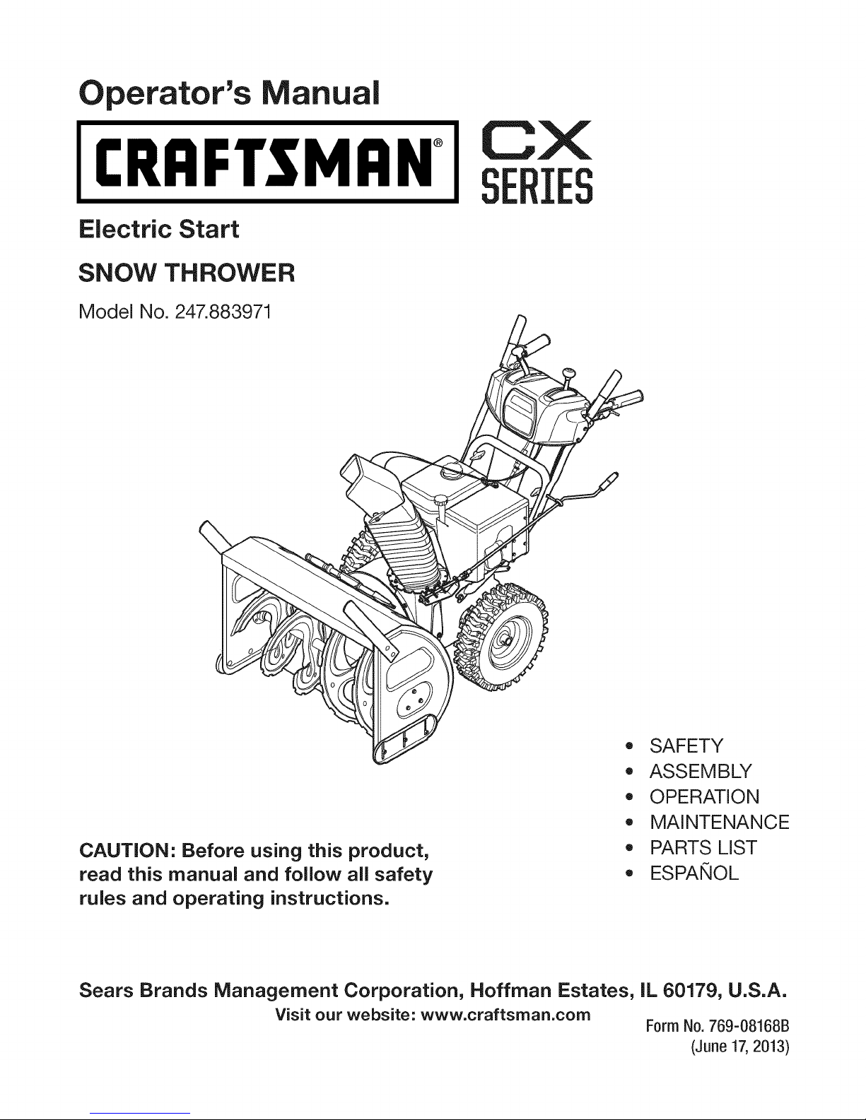
perator's nual
I:RRFrSMAN+
Electric Start
SNOW THROWER
Model No. 247.883971
CX
IES
CAUTION" Before using this product,
read this manual and follow all safety
rules and operating instructions.
Sears Brands Management Corporation, Hoffman Estates, IL 60179, U.S.A.
Visit our website: www.craftsman.com
,, SAFETY
o ASSEMBLY
OPERATION
MAINTENANCE
PARTS LIST
o ESPANOL
Form No.769-08168B
(June 17,2013)
Page 2
Warranty Statement .................................. Page 2
Safe Operation Practices .......................... Page 3
Assembly .................................................. Page 7
Operation .................................................. Page 12
Service and Maintenance ......................... Page 17
Off-Season Storage .................................. Page 25
Troubleshooting ........................................ Page 27
Parts List ................................................... Page 28
Repair Protection Agreement ................... Page 47
Espa_ol ..................................................... Page 48
Service Numbers ...................................... Back Cover
CRAFTSMANCXTWOYEARFULLWARRANTY
FORTWOYEARSfromthe dateofpurchase,thisproductiswarrantedagainstanydefectsin materialorworkmanship.A defective
productwillreceivefree repairorreplacementif repairisunavailable.
Forwarranty coveragedetails to obtain free repairor replacement,visitthe website: www.craftsman.com
Thiswarranty coversONLYdefects in materialandworkmanship. Warranty coveragedoes NOTinclude:
• Expendableitemsthatcanwearoutfromnormalusewithinthewarrantyperiod,includingbutnotlimitedtoaugers,augerpaddles,
driftcutters,skidshoes,shaveplate,shearpins,sparkplug,aircleaner,belts,andoil filter.
• Standardmaintenanceservicing,oilchanges,or tune-ups.
• Tirereplacementorrepaircausedbypuncturesfromoutsideobjects,suchasnails,thorns,stumps,orglass.
• Tireor wheelreplacementor repairresultingfromnormalwear,accident,orimproperoperationormaintenance.
• Repairsnecessarybecauseofoperatorabuse,includingbutnotlimitedto damagecausedbyover-speedingtheengine,orfrom
impactingobjectsthatbendthe frame,augershaft,etc.
• Repairsnecessarybecauseofoperatornegligence,includingbutnotlimitedto,electricaland mechanicaldamagecausedby
improperstorage,failureto usethepropergradeandamountof engineoil,or failureto maintaintheequipmentaccordingtothe
instructionscontainedintheoperator'smanual.
• Engine(fuelsystem)cleaningorrepairscausedbyfuel determinedtobecontaminatedor oxidized(stale).Ingeneral,fuelshouldbe
usedwithin30 daysofitspurchasedate.
• Normaldeteriorationandwearof theexteriorfinishes,orproductlabelreplacement.
Thiswarrantyisvoidif thisproductiseverusedwhileprovidingcommercialservicesor if rentedtoanotherperson.
Thiswarrantygivesyouspecificlegalrights,andyoumayalsohaveotherrightswhichvaryfromstatetostate.
SearsBrands ManagementCorporation, Hoffman Estates, IL 60179
EngineOilType: 5W-30
EngineOilCapacity: 37ounces
FuelCapacity: Approx.5 Quarts
SparkPlug: F6RTC(951-10292)
SparkPlugGap: .020"to.030"
© SearsBrands,LLC
Model Number.................................................................
Serial Number.................................................................
Dateof Purchase.............................................................
Recordthemodelnumber,serialnumber
anddateof purchaseabove
2
Page 3
Thissymbolpointsout importantsafety instructionswhich,if not
followed,couldendangerthe personalsafetyand/orproperty of
yourselfandothers.Readandfollow all instructionsinthis manual
beforeattempting to operatethis machine.Failuretocomplywith these
instructionsmayresultinpersonalinjury.Whenyouseethis symbol,HEED
ITSWARNING!
Thismachinewasbuilt to beoperatedaccordingtothesafeoperation
practicesinthismanual.Aswith anytype of powerequipment,
carelessnessorerroronthe part ofthe operatorcanresultinseriousinjury.
Thismachineiscapableof amputatingfingers, hands,toesandfeet and
throwingdebris.Failuretoobservethefollowing safety instructionscould
resultinseriousinjuryordeath.
CALIFORNIA PROPOSITION 65
EngineExhaust,someofits constituents,and certainvehiclecomponents
containor emit chemicalsknownto Stateof Californiatocausecancerand
birth defectsorother reproductiveharm.
TRAINING
Read,understand,andfollowall instructionsonthemachineandinthe
manual(s)beforeattemptingtoassembleandoperate.Failuretodosocan
resultinseriousinjurytotheoperatorand/orbystanders.Keepthismanual
inasafeplaceforfutureandregularreferenceandfororderingreplacement
parts.
Befamiliarwith allcontrolsandtheirproperoperation.Knowhowtostop
themachineanddisengagethemquickly.
Neverallowchildrenunder14yearsofagetooperatethismachine.Children
14andovershouldreadandunderstandtheinstructionsandsafeoperation
practicesinthis manualandonthemachineandbetrainedandsupervised
byanadult.
Neverallowadultsto operatethismachinewithout properinstruction.
Thrownobjectscancauseseriouspersonalinjury.Planyoursnow-throwing
patterntoavoiddischargeofmaterialtowardroads,bystandersandthelike.
Keepbystanders,petsandchildrenat least75feetfromthemachinewhileit
isin operation.Stopmachineif anyoneentersthearea.
Exercisecautiontoavoidslippingorfalling,especiallywhenoperatingin
reverse.
PREPARATION
Thoroughlyinspecttheareawheretheequipmentistobeused.Removeall
doormats,newspapers,sleds,boards,wiresandotherforeignobjects,which
couldbetrippedoverorthrownbytheauger/impeller.
Alwayswearsafetyglassesoreyeshieldsduringoperationandwhile
performinganadjustmentor repairto protectyoureyes.Thrownobjects
whichricochetcancauseseriousinjuryto theeyes.
Donotoperatewithout wearingadequatewinteroutergarments.Donot
wearjewelry,longscarvesorotherlooseclothing,whichcouldbecome
entangledinmovingparts.Wearfootwearwhichwill improvefootingon
slipperysurfaces.
Usea groundedthree-wireextensioncordandreceptacleforallmachines
with electricstartengines.
Your Responsibility--Restrict theuseofthis powermachineto
personswhoread,understandandfollow thewarningsandinstructionsin
thismanualandonthe machine.
SAVETHESEINSTRUCTIONS!
Disengageallcontrolleversbeforestartingtheengine.
Adjustcollectorhousingheighttocleargravelorcrushedrocksurfaces.
Neverattempttomakeanyadjustmentswhileengineisrunning,except
wherespecificallyrecommendedintheoperator'smanual.
Letengineandmachineadjusttooutdoortemperaturebeforestartingto
clearsnow.
Safe Handling of Gasoline:
Toavoidpersonalinjuryor propertydamageuseextremecareinhandling
gasoline.Gasolineisextremely flammableandthe vaporsareexplosive.
Seriouspersonalinjurycanoccurwhengasolineisspilledonyourselforyour
clotheswhichcanignite.Washyourskinandchangeclothesimmediately.
Useonlyanapprovedgasolinecontainer.
Neverfill containersinsidea vehicleoronatruckortrailerbedwitha plastic
liner.Alwaysplacecontainersonthegroundawayfromyourvehiclebefore
filling.
Whenpractical,removegas-poweredequipmentfromthetruckor
trailerandrefuelitontheground.Ifthisis notpossible,thenrefuelsuch
equipmentonatrailerwith aportablecontainer,ratherthanfromagasoline
dispensernozzle.
Keepthenozzleincontactwiththerimofthefueltankorcontaineropening
atalltimesuntilfuelingiscomplete.Donotuseanozzlelock-opendevice.
Extinguishallcigarettes,cigars,pipesandothersourcesofignition.
Neverfuelmachineindoors.
Neverremovegascaporaddfuelwhiletheengineishotorrunning.Allow
enginetocoolatleasttwominutesbeforerefueling.
Neveroverfill fueltank.Filltankto nomorethan1/2inchbelowbottomof
fillernecktoallowspaceforfuelexpansion.
Replacegasolinecapandtightensecurely.
Ifgasolineisspilled,wipeit offthe engineandequipment.Moveunitto
anotherarea.Wait.5minutesbeforestartingtheengine.
Page 4
Toreducefirehazards,keepmachinefreeofgrass,leaves,orotherdebris
build-up.Cleanupoilorfuelspillageandremoveanyfuelsoakeddebris.
Neverstorethemachineorfuelcontainerinsidewherethereisanopen
flame,sparkorpilotlightasonawaterheater,spaceheater,furnace,clothes
dryerorothergasappliances.
OPERATION
Donotputhandsorfeetnearrotatingparts,intheauger/impellerhousing
orchuteassembly.Contactwith therotatingpartscanamputatehandsand
feet.
Theauger/impellercontrolleverisasafetydevice.Neverbypassits
operation.Doingsomakesthemachineunsafeandmaycausepersonal
injury.
Thecontrolleversmustoperateeasilyin bothdirectionsandautomatically
returntothedisengagedpositionwhenreleased.
Neveroperatewith amissingordamagedchuteassembly.Keepallsafety
devicesinplaceandworking.
Neverrunanengineindoorsor inapoorlyventilatedarea.Engineexhaust
containscarbonmonoxide,anodorlessanddeadlygas.
Donotoperatemachinewhileundertheinfluenceof alcoholordrugs.
Mufflerandenginebecomehotandcancauseaburn.Donottouch.Keep
childrenaway.
Exerciseextremecautionwhenoperatingonorcrossinggravelsurfaces.Stay
alertforhiddenhazardsortraffic.
Exercisecautionwhenchangingdirectionandwhileoperatingonslopes.Do
notoperateonsteepslopes.
Planyoursnow-throwingpatterntoavoiddischargetowardswindows,
walls,carsetc.Thus,avoidingpossiblepropertydamageorpersonalinjury
causedbyaricochet.
Neverdirectdischargeatchildren,bystandersandpetsor allowanyonein
frontofthemachine.
Donotoverloadmachinecapacitybyattemptingtoclearsnowattoofastof
arate.
Neveroperatethismachinewithoutgoodvisibilityorlight.Alwaysbesureof
yourfootingandkeepafirm holdonthehandles.Walk,neverrun.
Disengagepowertotheauger/impellerwhentransportingornotinuse.
Neveroperatemachineathightransportspeedsonslipperysurfaces.Look
downandbehindandusecarewhenbackingup.
Ifthemachineshouldstartto vibrateabnormally,stoptheengine,
disconnectthesparkplugwire andgrounditagainsttheengine.Inspect
thoroughlyfordamage.Repairanydamagebeforestartingandoperating.
Disengageallcontrolleversandstopenginebeforeyouleavetheoperating
position(behindthehandles).Waituntiltheauger/impellercomesto
acompletestopbeforeuncloggingthechuteassembly,makingany
adjustments,orinspections.
Neverputyourhandin thedischargeorcollectoropenings.Donotunclog
chuteassemblywhileengineisrunning.Shutoff engineandremainbehind
handlesuntilallmovingpartshavestoppedbeforeunclogging.
Useonlyattachmentsandaccessoriesapprovedbythemanufacturer(e.g.
wheelweights,tirechains,cabsetc.).
Whenstartingengine,pull cordslowlyuntilresistanceisfelt,thenpull
rapidly.Rapidretractionofstartercord(kickback)will pullhandandarm
towardenginefasterthanyoucanletgo.Brokenbones,fractures,bruisesor
sprainscouldresult.
Ifsituationsoccurwhicharenotcoveredinthismanual,usecareandgood
judgment.
CLEARING A CLOGGED DISCHARGE CHUTE
Handcontactwiththerotatingimpellerinsidethedischargechuteisthemost
commoncauseof injuryassociatedwithsnowthrowers.Neveruseyourhandto
cleanoutthedischargechute.
Toclearthechute:
a. SHUTTHEENGINEOFF!
b. Wait10secondsto besuretheimpellerbladeshavestopped
rotating.
c. Alwaysuseaclean-outtool,notyourhands.
MAINTENANCE & STORAGE
Nevertamperwithsafetydevices.Checktheirproperoperationregularly.
Refertothemaintenanceandadjustmentsectionsofthismanual.
Beforecleaning,repairing,orinspectingmachinedisengageallcontrol
leversandstoptheengine.Waituntiltheauger/impellercometoacomplete
stop.Disconnectthesparkplugwireandgroundagainsttheengineto
preventunintendedstarting.
Checkboltsandscrewsforpropertightnessatfrequentintervalsto keepthe
machineinsafeworkingcondition.Also,visuallyinspectmachineforany
damage.
Donotchangetheenginegovernorsettingorover-speedtheengine.The
governorcontrolsthemaximumsafeoperatingspeedoftheengine.
Snowthrowershaveplatesandskidshoesaresubjecttowearanddamage.
Foryoursafetyprotection,frequentlycheckallcomponentsandreplace
with originalequipmentmanufacturer's(OEM)partsonlyaslistedinthe
Partspagesofthisoperator'smanual.Useof partswhichdonot meetthe
originalequipmentspecificationsmayleadtoimproperperformanceand
compromisesafety!
Checkcontrolleversperiodicallytoverifytheyengageanddisengage
properlyandadjust,ifnecessary.Refertotheadjustmentsectioninthis
operator'smanualfor instructions.
Maintainorreplacesafetyandinstructionlabels,asnecessary.
Observeproperdisposallawsandregulationsforgas,oil,etc.toprotectthe
environment.
Priortostoring,runmachineafewminutestoclearsnowfrommachineand
preventfreezeupofauger/impeller.
Neverstorethemachineorfuelcontainerinsidewherethereisanopen
flame,sparkorpilotlight suchasa waterheater,furnace,clothesdryeretc.
Alwaysrefertotheoperator'smanualforproperinstructionsonoff-season
storage.
4
Page 5
Checkfuelline,tank,cap,andfittingsfrequentlyforcracksor leaks.Replace
if necessary.
Donotcrankenginewith sparkplugremoved.
AccordingtotheConsumerProductsSafetyCommission(CPSC)andthe
U.S.EnvironmentalProtectionAgency(EPA),thisproducthasanAverage
Useful Lifeofseven(7)years,or60hoursofoperation.Attheendof
theAverage Useful Lifehavethemachineinspectedannuallybyan
authorizedservicedealertoensurethatallmechanicalandsafetysystems
areworkingproperlyandnotwornexcessively.Failureto dosocanresultin
accidents,injuriesordeath.
DO NOT MODIFY ENGINE
Toavoidseriousinjuryordeath,donotmodifyengineinanyway.Tampering
with the governorsetting canleadto arunawayengineandcauseit to
operateat unsafespeeds.Nevertamperwith factorysetting ofengine
governor.
NOTICE REGARDING EMiSSiONS
Engineswhichare certifiedto complywith Californiaandfederal EPA
emissionregulationsfor SORE(SmallOffRoadEquipment)arecertified
tooperateonregularunleadedgasoline,and mayincludethe following
emissioncontrolsystems:EngineModification (EM),OxidizingCatalyst(0C),
SecondaryAir injection(SAI)andThreeWayCatalyst(TWC)if soequipped.
SPARK ARRESTOR
e
Thismachineisequippedwith an internalcombustionengineandshould
not beusedonornearanyunimprovedforest-covered,brushcoveredor
grass-coveredland unlessthe engine'sexhaustsystemisequippedwith a
sparkarrestormeetingapplicablelocalorstatelaws(if any).
Ira sparkarrestorisused,it shouldbemaintainedin effectiveworking order
bythe operator.IntheState ofCaliforniathe aboveisrequired bylaw (Section
4442ofthe CaliforniaPublicResourcesCode).Otherstates mayhavesimilar
laws.Federallawsapplyonfederal lands.
Asparkarrestorfor the muffler isavailablethroughyournearestSearsParts
andRepairServiceCenter.
Page 6
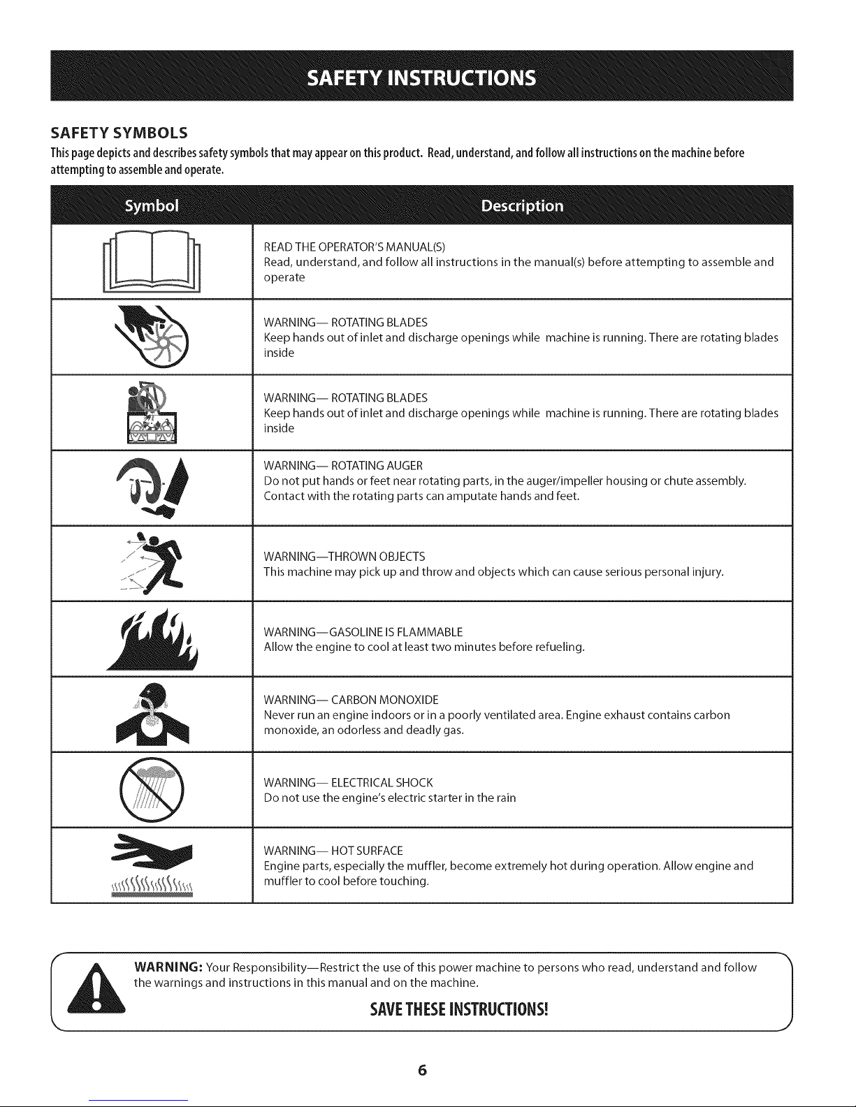
SAFETY SYMBOLS
Thispage depicts and describes safety symbols that may appear on this product. Read, understand, and follow all instructions on the machine before
attempting to assemble and operate.
READ THE OPERATOR'S MANUAL(S)
Read, understand, and follow all instructions in the manual(s) before attempting to assemble and
operate
WARNING-- ROTATING BLADES
Keep hands out of inlet and discharge openings while machine is running. There are rotating blades
inside
WARNING-- ROTATING BLADES
Keep hands out of inlet and discharge openings while machine is running. There are rotating blades
inside
WARNING-- ROTATING AUGER
Do not put hands or feet near rotating parts, in the auger/impeller housing or chute assembly.
Contact with the rotating parts can amputate hands and feet.
WARNING--THROWN OBJECTS
This machine may pick up and throw and objects which can cause serious personal injury.
WARNING--GASOLINE IS FLAMMABLE
Allow the engine to cool at least two minutes before refueling.
WARNING-- CARBON MONOXIDE
Never run an engine indoors or in a poorly ventilated area. Engine exhaust contains carbon
monoxide, an odorless and deadly gas.
WARNING-- ELECTRICAL SHOCK
Do not use the engine's electric starter in the rain
WARNING-- HOT SURFACE
Engine parts, especially the muffler, become extremely hot during operation. Allow engine and
muffler to cool before touching.
WARNING: Your Responsibility--Restrict the use of this power machine to persons who read, understand and follow
the warnings and instructions in this manual and on the machine.
SAVETHESEiNSTRUCTIONS!
6
Page 7
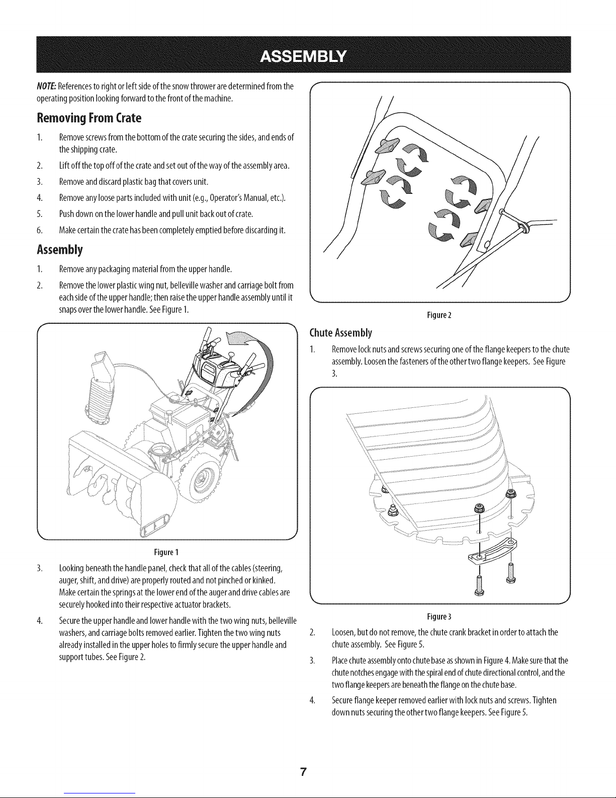
NOTE:Referencesto rightorleftsideofthesnowthroweraredeterminedfromthe
operatingpositionlookingforwardto thefrontofthemachine.
Removing From (:rate
1. Removescrewsfromthebottomofthecratesecuringthesides,andendsof
theshippingcrate.
2. Liftoff thetopoffofthecrateandsetoutof thewayoftheassemblyarea.
3. Removeanddiscardplasticbagthat coversunit.
4. Removeanyloosepartsincludedwithunit(e.g.,Operator'sManual,etc.).
5. Pushdownonthe lowerhandleandpullunitbackoutofcrate.
6. Makecertainthecratehasbeencompletelyemptiedbeforediscardingit.
Assembly
1. Removeanypackagingmaterialfromtheupperhandle.
2. Removethelowerplasticwingnut,bellevillewasherandcarriageboltfrom
eachsideoftheupperhandle;thenraisetheupperhandleassemblyuntilit
snapsoverthelowerhandle.SeeFigure1.
"_,r ,,J
Figure2
ChuteAssembly
1. Removelocknutsandscrewssecuringoneoftheflangekeeperstothechute
assembly.Loosenthefastenersoftheothertwoflangekeepers.SeeFigure
3.
Figure1
3. Lookingbeneaththehandlepanel,checkthatallofthecables(steering,
auger,shift,anddrive)areproperlyroutedandnotpinchedorkinked.
Makecertainthespringsatthelowerendoftheaugeranddrivecablesare
securelyhookedintotheirrespectiveactuatorbrackets.
4. Securetheupperhandleandlowerhandlewiththetwo wingnuts,belleville
washers,andcarriageboltsremovedearlier.Tightenthetwowingnuts
alreadyinstalledin theupperholestofirmly securetheupperhandleand
supporttubes.SeeFigure2.
f
Figure3
2. Loosen,butdonotremove,thechutecrankbracketinordertoattachthe
chuteassembly.SeeFigure5.
3. PlacechuteassemblyontochutebaseasshowninFigure4.Makesurethatthe
chutenotchesengagewith thespiralendofchutedirectionalcontrol,andthe
twoflangekeepersarebeneaththeflangeonthechutebase.
4. Secureflangekeeperremovedearlierwith locknutsandscrews.Tighten
downnutssecuringtheothertwoflangekeepers.SeeFigure5.
7
Page 8
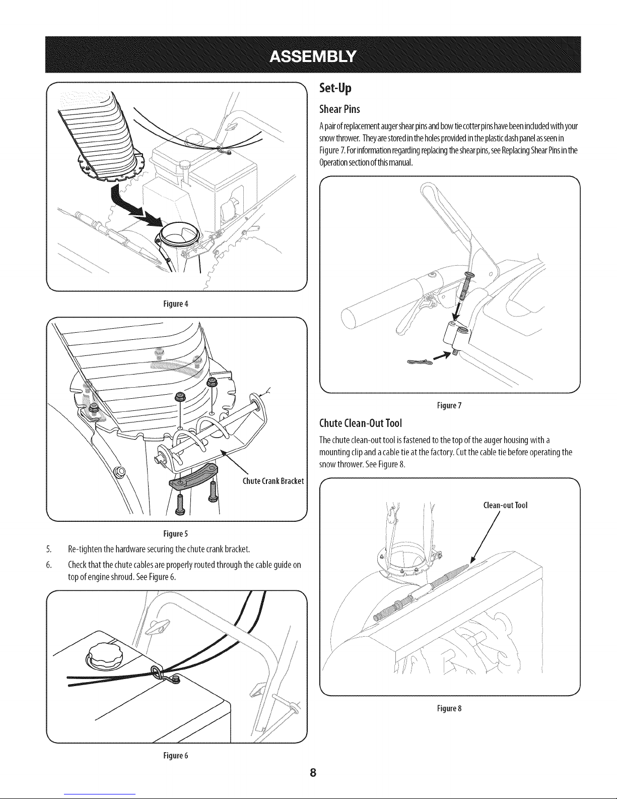
/ /
/ /
Set-Up
ShearPins
Apairofreplacementaugershearpinsandbowtiecotterpinshavebeenincludedwithyour
snowthrower.Theyarestoredintheholesprovidedintheplasticdashpanelasseenin
Figure7.Forinformationregardingreplacingtheshearpins,seeReplacingShearPinsinthe
Operationsectionofthismanual.
Figure4
Figure5
5.
Re-tightenthehardwaresecuringthechutecrankbracket.
6.
Checkthatthechutecablesareproperlyroutedthroughthecableguideon
topofengineshroud.SeeFigure6.
......
Figure7
ChuteClean-OutTool
Thechutedean-outtool isfastenedtothetopof theaugerhousingwitha
mountingclipandacabletieat thefactory.Cutthecabletie beforeoperatingthe
snowthrower.SeeFigure8.
Clean-outTool
Figure6
/
/
/
/
/
J
Figure8
8
Page 9
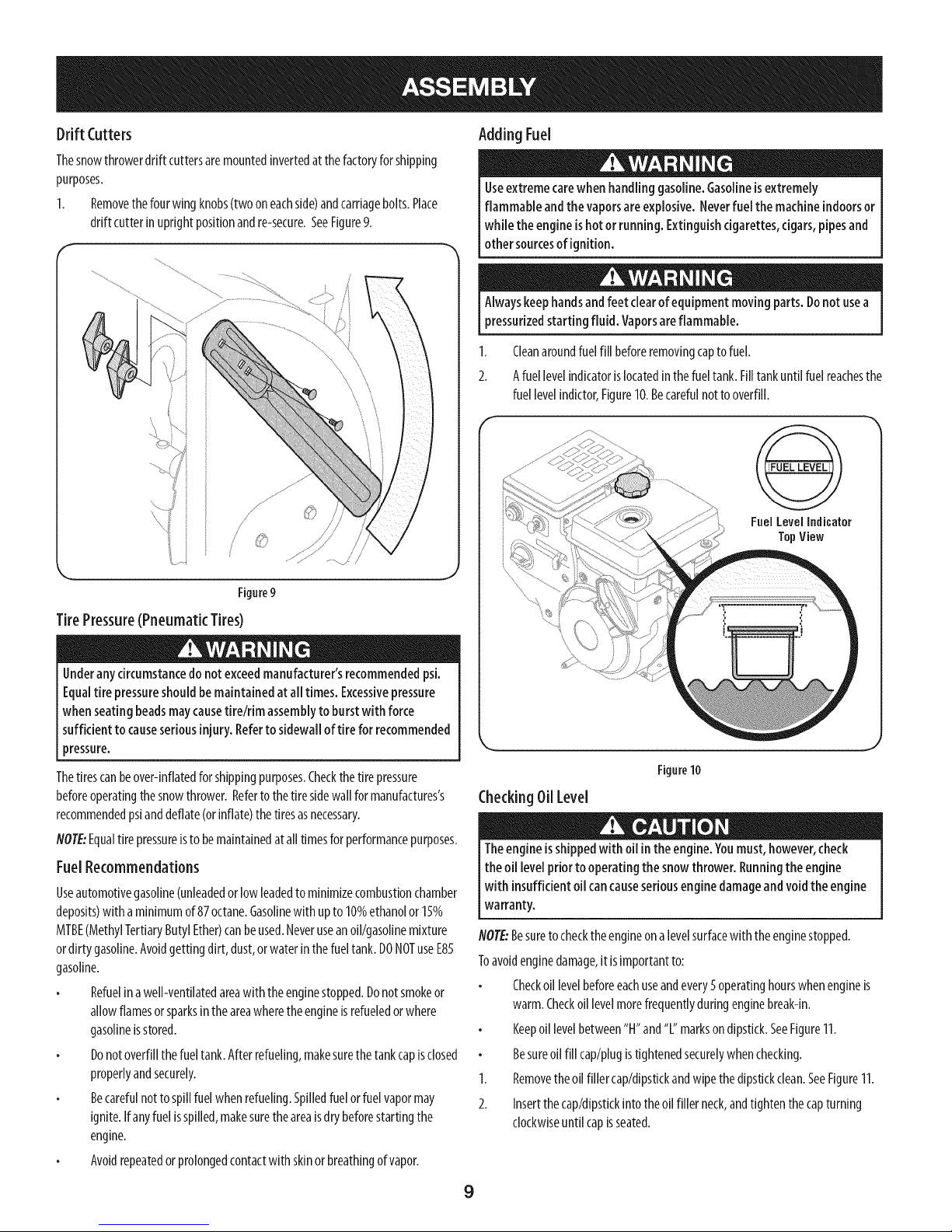
DriftCutters
Thesnowthrowerdrift cuttersaremountedinvertedatthefactoryforshipping
purposes.
1. Removethefourwing knobs(twooneachside)andcarriagebolts.Place
driftcutterinuprightpositionandre-secure.SeeFigure9.
Figure9
Adding Fuel
Useextremecarewhen handlinggasoline.Gasolineisextremely
flammable andthe vaporsareexplosive.Neverfuel the machineindoorsor
whiletheengineishotorrunning.Extinguishcigarettes,cigars,pipesand
othersourcesofignition.
Alwayskeephandsandfeet clearof equipmentmovingparts.Donot usea
pressurizedstarting fluid. Vaporsareflammable.
1. Cleanaroundfuelfillbeforeremovingcaptofuel.
2. Afuellevelindicatorislocatedinthefueltank.Filltankuntilfuelreachesthe
fuellevelindictor,Figure10,Becarefulnotto overfill,
FuelLevelIndicalor
TopView
J
TirePressure(Pneumatic Tires)
Underanycircumstancedonotexceedmanufacturer'srecommendedpsi.
Equaltire pressureshould bemaintainedatall times.Excessivepressure
whenseatingbeadsmaycausetire/rim assemblyto burstwithforce
sufficientto causeseriousinjury.Referto sidewalloftire forrecommended
pressure.
Thetirescanbeover-inflatedfor shippingpurposes.Checkthetire pressure
beforeoperatingthesnowthrower.Referto thetiresidewallformanufactures's
recommendedpsianddeflate(orinflate)thetiresasnecessary.
NOTE:Equaltire pressureisto bemaintainedat alltimesforperformancepurposes.
FuelRecommendations
Useautomotivegasoline(unleadedorlowleadedtominimizecombustionchamber
deposits)withaminimumof87octane.Gasolinewith upto10%ethanolor1__%
MTBE(MethylTertiaryButylEther)canbeused.Neveruseanoil/gasolinemixture
ordirtygasoline.Avoidgettingdirt, dust,orwaterinthefueltank.DONOTuseE85
gasoline.
Refuelinawell-ventilatedareawith theenginestopped.Donotsmokeor
allowflamesorsparksintheareawheretheengineisrefueledorwhere
gasolineisstored.
Donotoverfillthefueltank.Afterrefueling,makesurethetankcapisclosed
properlyandsecurely.
Becarefulnottospillfuelwhenrefueling.Spilledfuelorfuelvapormay
ignite.Ifanyfuelisspilled,makesuretheareaisdrybeforestartingthe
engine.
Avoidrepeatedorprolongedcontactwith skinorbreathingofvapor.
Figure10
CheckingOil Level
Theengineisshippedwithoilintheengine.Youmust, however,check
the oiilevel priorto operatingthesnowthrower. Runningthe engine
with insufficientoilcancauseseriousenginedamageandvoidthe engine
warranty.
NOTE:Besuretochecktheengineona levelsurfacewith theenginestopped.
Toavoidenginedamage,it isimportantto:
Checkoil levelbeforeeachuseandevery5operatinghourswhenengineis
warm.Checkoillevelmorefrequentlyduringenginebreak-in.
Keepoil levelbetween"H"and"L"marksondipstkk.SeeFigure11.
Besureoil fillcap/plugistightenedsecurelywhenchecking.
1. Removetheoil fillercap/dipstickandwipethedipstickclean.SeeFigure11.
2. Insertthecap/dipstickintotheoil fillerneck,andtightenthecapturning
clockwiseuntil capisseated.
9
Page 10

f
Figure11
NOTE:Onsomeengines,athreadedscrewcapwill bepresentinsteadofthequarter
turnlockingcap.Intheinstanceofathreadedoilcap/dipstkk,DONOTscrewthe
cap/dipstkkintocheck.Checktheoilbyrestingthecap/dipstkkonthethreads,but
notscrewingit in.
3. Removetheoilfillercap/dipstick.Ifthelevelislow,slowlyaddoil untiloil
levelregistersbetweenhigh(H)andlow(L),Figure11.
4. Replaceandtightencap/dipstkkfirmlybeforestartingengine.
NOTE:Donotoverfill.Overfillingwith oilmaycausesmoking,hardstarting,or
sparkplugfouling.
NOTE:DONOTallowoilleveltofall belowthe"L" markonthedipstick.Doingso
mayresultinequipmentmalfunctionsordamage.
NOTE"Tochangetheoilonyourengine,seetheMaintenanceSectionoftheengine
operator'smanualincludedwith thesnowthrower.
Adjustments
SkidShoes
Thesnowthrowerskidshoesareadjustedupwardat thefactoryforshipping
purposes.Adjustthemdownwardpriortooperatingthesnowthrower.
It isnotrecommendedthat you operatethis snowthrowerongravelas
it caneasilypickupand throw loosegravel,causingpersonalinjury or
damagetothe snowthrower andsurroundingproperty.
Forclosesnowremovalonasmoothsurface,adjusttheskidshoessothattheshaveplate
onthebottomofthe augerhousingisjustofftheground.
Adjusttheskidshoesto alowerpositionto raisetheshaveplateoffthe ground
whenclearingunevenareas,suchasa ribbontypedrivewayoragraveldriveway
NOTE:Ifyouchoosetooperatethesnowthroweronagravelsurface,keeptheskid
shoesin positionformaximumclearancebetweenthegroundandtheshaveplate.
2. Whileobservingthedistancebetweentheshaveplateandtheground,
adjusttheskidsshoesupordowntoachievethedesiredshaveplateheight.
SeeFigure12.
3. Makecertaintheentirebottomsurfaceofskidshoesareagainsttheground
toavoidunevenwearontheskidshoes;thentightennutsandboltssecurely.
Lower
Shave
ShavePlate
Figure12
Plate
Raise
Shave
Plate
_J
Augerand DriveControl Cables
Priorto operatingyoursnowthrower,carefullyreadandfollowall
instructionsbelow.Performall adjustmentsto verifyyoursnowthroweris
operatingsafelyandproperly.
TestingAugerDrive Control
1. Whentheaugercontrolis releasedandinthedisengaged"up"position,the
cableshouldhaveverylittle slack.It shouldNOTbetight. Referto Figure13.
2. Inawell-ventilatedarea,startthesnowthrowerengineasinstructedinthe
Operationsectionofthis manual.MakesurethethrottleissetintheFAST
position.
3. Whilestandingintheoperator'sposition(behindthesnowthrower),engage
theauger.
4. Allowtheaugertoremainengagedforapproximatelyten(10)seconds
beforereleasingtheaugercontrol.Repeatthisseveraltimes.
NOTE:Whenengagingtheauger,youmayheara"chirp"sound.Thisis
normal,it isthe beltengagingthepulley.Asthebeltwears,thissoundwill
not beheardwhenengagingtheauger.
5. WiththethrottlecontrolintheFAST(rabbit)positionandtheaugercontrol
in thedisengaged"up"position,walktothefrontof themachine.
Toadjust the skidshoes:
1. Adjustskidshoesbylooseningthesix(threeoneachside)hexnutsand
carriageboltssecuringtheskidshoesto theaugerhousing.RefertoFigure
12.
10
Page 11
6.
ConfirmthattheaugerhascompletelystoppedrotatingandshowsNOsigns
ofmotion.IftheaugershowsANYsignsof rotating,immediatelyreturnto
theoperator'spositionandshutoffthe engine.WaitforALLmovingpartsto
stopbeforere-adjustingtheaugercontrol.
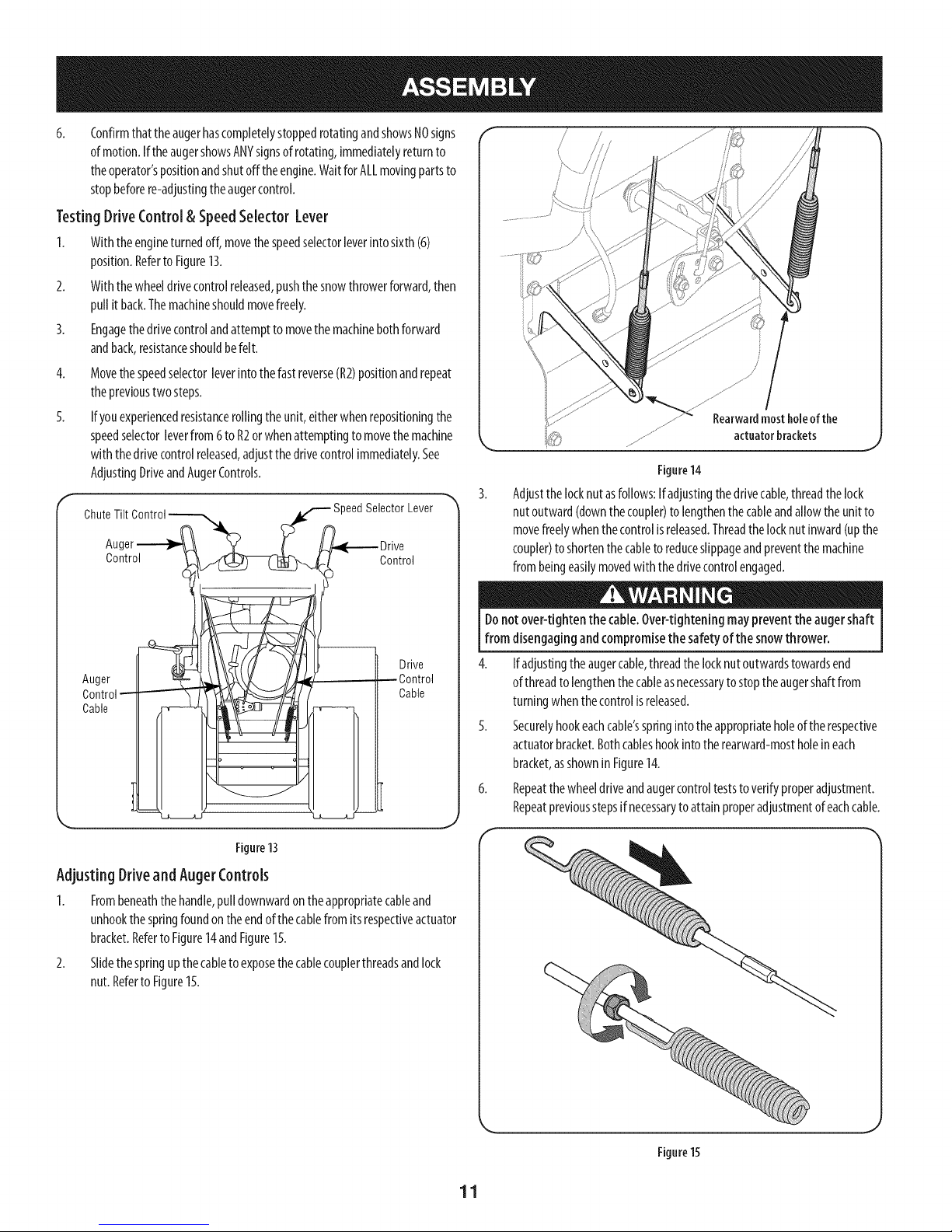
TestingDriveControl& SpeedSelector Lever
1. Withtheengineturnedoff,movethespeedselectorleverintosixth(6)
position.Referto Figure13.
2. Withthewheeldrivecontrolreleased,pushthesnowthrowerforward,then
pullit back.Themachineshouldmovefreely.
3. Engagethedrivecontrolandattempttomovethemachinebothforward
andback,resistanceshouldbefelt.
4.
Movethespeedselectorleverintothefastreverse(R2)positionandrepeat
theprevioustwosteps.
5.
Ifyouexperiencedresistancerollingtheunit,eitherwhenrepositioningthe
speedselectorleverfrom6toR2orwhenattemptingtomovethemachine
with thedrivecontrolreleased,adjustthedrivecontrolimmediately.See
AdjustingDriveandAugerControls.
ChuteTilt
Auc
Control Control
_eedSelectorLever
/
Figure14
Adjustthelocknutasfollows:If adjustingthedrivecable,threadthelock
nutoutward(downthecoupler)tolengthenthecableandallowtheunit to
movefreelywhenthecontrolisreleased.Threadthelocknutinward(upthe
coupler)toshortenthecabletoreduceslippageandpreventthemachine
frombeingeasilymovedwith thedrivecontrolengaged.
Drive
Auger
Control
Cable
Figure13
--Control
Cable
Adjusting Drive and AugerControls
1. Frombeneaththehandle,pulldownwardontheappropriatecableand
unhookthespringfoundontheendofthecablefromitsrespectiveactuator
bracket.Referto Figure14andFigure15.
2. Slidethespringupthecabletoexposethecablecouplerthreadsandlock
nut.RefertoFigure15.
Donotover-tightenthe cable.Over-tighteningmaypreventthe augershaft
from disengagingandcompromisethe safetyof the snowthrower.
4. Ifadjustingtheaugercable,threadthelocknutoutwardstowardsend
ofthreadtolengthenthecableasnecessarytostoptheaugershaftfrom
turningwhenthecontrolisreleased.
5. Securelyhookeachcable'sspringintotheappropriateholeoftherespective
actuatorbracket.Bothcableshookintotherearward-mostholeineach
bracket,asshownin Figure14.
6. Repeatthewheeldriveandaugercontrolteststo verifyproperadjustment.
Repeatpreviousstepsif necessarytoattainproperadjustmentofeachcable.
Figure15
11
Page 12
WheelDriveControl
Headlight _eedSelectorLever
FuelTank
ChutePitch Control"
erControl
FuelCap
OilFill WheelSteeringControl
ChuteAssemb[
DriftCutter
AugerHousing
Auger
SnowthrowercontrolsandfeaturesaredescribedbelowandillustratedinFigure
16.
Speedselector Lever
Thespeedselectorleverislocatedintheright sideofthe handle
panelandisusedtodeterminegroundspeedanddirectionof
travel.
Forward
Therearesixforward(F)speeds.Positionone(1)istheslowestand
positionsix(6)isthe fastest.
Reverse
Therearetwo reverse(R)speeds.One(R1)isthe slowerandtwo
(R2)isthefaster.
6
5
4
3
t 2
F1
R1
ChuteDirectionalControl
OilFiller
Cap/Dipstick
Primer I ,-- FuNFill
Ch_ - StarterHandle
_Skid Shoe
OilDrain
Figure16
ChokeControl
Thechokecontrolisfoundontherearoftheengineand
isactivatedbyrotatingthecontrolcounter-clockwise.
Activatingthechokecontrolclosesthechokeplateonthe
carburetorandaidsinstartingtheengine.
Key
Thekeyisasafetydevice.Itmustbefully insertedintothe
ignitioninorderfortheenginetostart.Removethekey
whenthesnowthrowerisnotin use.
IMPORTANT:Donotturnthekeyinanattempttostartthe
engine.Doingsomaycauseit tobreak.
_ Electric
_ Start
Button
f Bectric
tL_ Switch Box
Craftsman Snow Throwers conform to the safety standard of the American National Standards institute (ANSI).
R2
Meets ANSi Safety Standards
12
Page 13
ThrottleControl
===..__
Thethrottlecontrolislocatedontherearoftheengine.Itregulatesthespeedofthe
engineandwillshutoffthe enginewhenmovedintotheSTOPposition.
Primer
carburetortoaidinstartinga"Cold"engine,orrestartinga
Pressingtheprimerforcesfueldirectlyintotheengine's I _,_P_.._.L
warmengine.
OilFill
Engineoillevelcanbecheckedandoiladdedthroughtheoil fill.
OilDrain
Engineoilcanbedrainedthroughtheoil drain.
FuelCap
Un-threadthegascaptoaddgasolinetothefueltank.
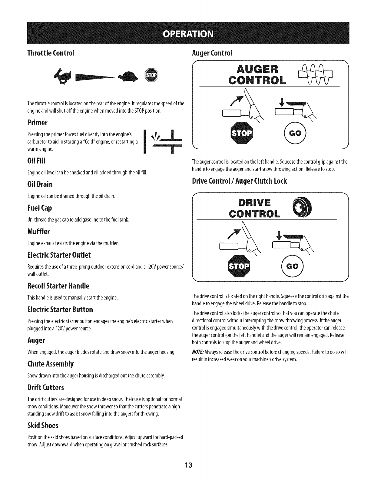
AugerControl
Theaugercontrolislocatedontheleft handle.Squeezethecontrolgripagainstthe
handletoengagetheaugerandstartsnowthrowingaction.Releasetostop.
DriveControl/ AugerClutchLock
Muffler
Engineexhaustexiststheengineviathemuffler.
ElectricStarterOutlet
Requirestheuseofathree-prongoutdoorextensioncordanda120Vpowersource/
walloutlet.
RecoilStarter Handle
Thishandleisusedto manuallystarttheengine.
ElectricStarterButton
Pressingtheelectricstarterbuttonengagestheengine'selectricstarterwhen
pluggedintoa 120Vpowersource.
Auger
Whenengaged,theaugerbladesrotateanddrawsnowintotheaugerhousing.
ChuteAssembly
Snowdrawnintotheaugerhousingisdischargedoutthechuteassembly.
Drift Cutters
Thedrift cuttersaredesignedforusein deepsnow.Theiruseisoptionalfornormal
snowconditions.Maneuverthesnowthrowersothatthecutterspenetratea high
standingsnowdriftto assistsnowfallingintotheaugersforthrowing.
Thedrivecontrolislocatedontheright handle.Squeezethecontrolgripagainstthe
handletoengagethewheeldrive.Releasethehandleto stop.
Thedrivecontrolalsolockstheaugercontrolsothatyoucanoperatethechute
directionalcontrolwithoutinterruptingthesnowthrowingprocess.Iftheauger
controlisengagedsimultaneouslywiththedrivecontrol,theoperatorcanrelease
theaugercontrol(ontheleft handle)andtheaugerwill remainengaged.Release
bothcontrolstostoptheaugerandwheeldrive.
NOTE:Alwaysreleasethedrivecontrolbeforechangingspeeds.Failuretodosowill
resultinincreasedwearonyourmachine'sdrivesystem.
SkidShoes
Positiontheskidshoesbasedonsurfaceconditions.Adjustupwardforhard-packed
snow.Adjustdownwardwhenoperatingongravelorcrushedrocksurfaces.
13
Page 14
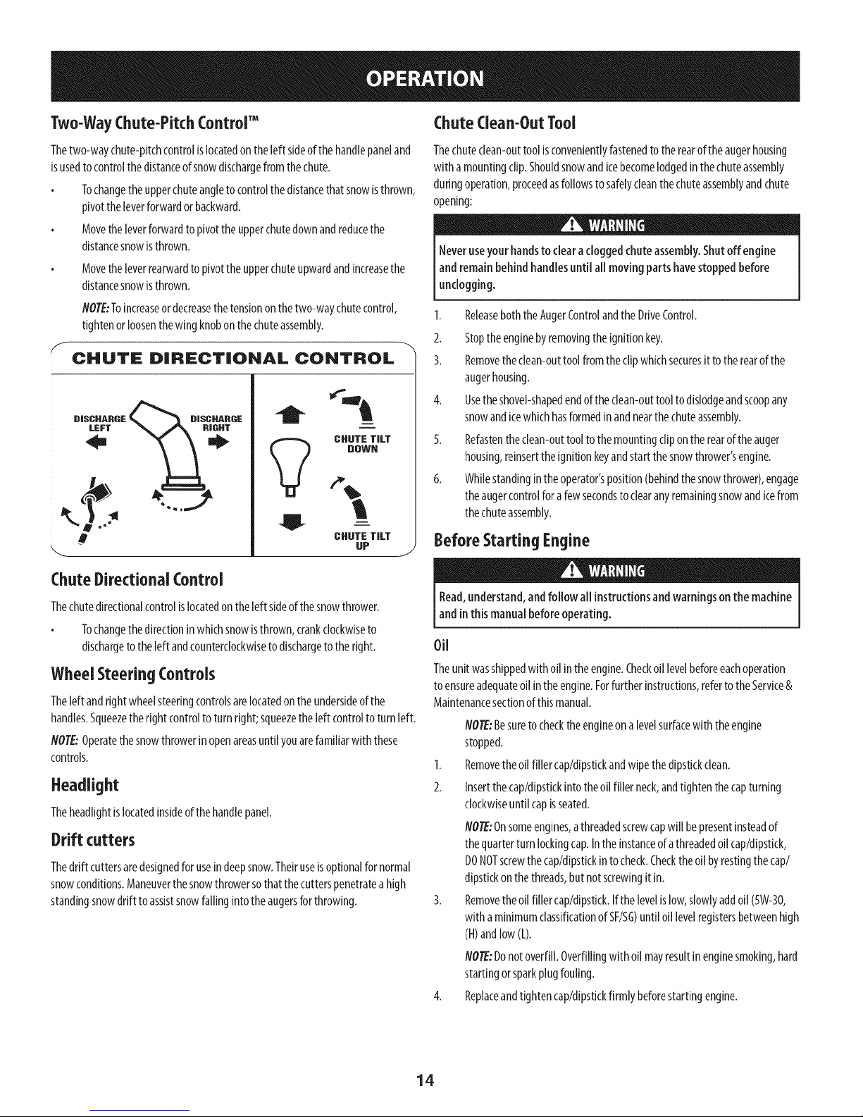
Two-WayChute-PitchControlTM
Chute Clean-Out Tool
Thetwo-waychute-pitchcontrolislocatedonthe[eftsideofthe handlepaneland
isusedto controlthedistanceof snowdischargefromthechute.
Tochangetheupperchuteangletocontrolthedistancethatsnowisthrown,
pivotthe[everforwardorbackward.
Movethe[everforwardtopivotthe upperchutedownandreducethe
distancesnowisthrown.
Movetheleverrearwardtopivottheupperchuteupwardandincreasethe
distancesnowisthrown.
NOTE:Toincreaseordecreasethetensiononthetwo-waychutecontrol,
tightenorloosenthewingknobonthechuteassembly.
CHUTE DiRECTiONAL CONTROL
D|SCHABGE _ D|SCHARGE
m
i
CHUTE TILT
DOWN
CHUTE TILT
UP
J
Thechuteclean-outtoolisconvenientlyfastenedtotherearoftheaugerhousing
with amountingclip.Shouldsnowandicebecomelodgedinthechuteassembly
duringoperation,proceedasfollowstosafelycleanthechuteassemblyandchute
opening:
Neveruseyourhandsto clearacloggedchuteassembly.Shutoff engine
andremainbehindhandlesuntilall movingpartshavestoppedbefore
unclogging.
1. ReleaseboththeAugerControlandtheDriveControl.
2. Stoptheenginebyremovingtheignitionkey.
3. Removetheclean-outtool fromtheclipwhichsecuresit totherearof the
augerhousing.
4. Usetheshovel-shapedendoftheclean-outtooltodislodgeandscoopany
snowandicewhichhasformedinandnearthechuteassembly.
5. Refastentheclean-outtoolto themountingclipontherearoftheauger
housing,reinserttheignitionkeyandstartthesnowthrower'sengine.
6. Whilestandingintheoperator'sposition(behindthesnowthrower),engage
theaugercontrolforafewsecondstoclearanyremainingsnowandicefrom
thechuteassembly.
Before Starting Engine
ChuteDirectional Control
Thechutedirectionalcontrolislocatedontheleft sideof thesnowthrower.
Tochangethedirectioninwhichsnowisthrown,crankclockwiseto
dischargetotheleftandcounterclockwiseto dischargeto theright.
Wheel Steering Controls
Theleftandrightwheelsteeringcontrolsarelocatedontheundersideofthe
handles.Squeezetheright controlto turnright;squeezetheleft controltoturnleft.
NOTE:Operatethesnowthrowerinopenareasuntilyouarefamiliarwith these
controls.
Headlight
Theheadlightis locatedinsideofthehandlepanel.
Drift cutters
Thedrift cuttersaredesignedfor useindeepsnow.Theiruseisoptionalfornormal
snowconditions.Maneuverthesnowthrowersothatthecutterspenetratea high
standingsnowdriftto assistsnowfallingintotheaugersforthrowing.
Read,understand,andfollow all instructionsandwarningsonthe machine
andinthis manualbeforeoperating.
Oil
Theunitwasshippedwithoil intheengine.Checkoil levelbeforeeachoperation
toensureadequateoil intheengine.Forfurtherinstructions,refertotheService&
Maintenancesectionofthismanual.
NOTE:Besureto checktheengineonalevelsurfacewith theengine
stopped.
1. Removetheoil fillercap/dipstickandwipethedipstickclean.
2. Insertthecap/dipstickintotheoil fillerneck,andtightenthecapturning
clockwiseuntil capisseated.
NOTE:Onsomeengines,athreadedscrewcapwill bepresentinsteadof
thequarterturnlockingcap.Inthe instanceof athreadedoilcap/dipstick,
DONOTscrewthecap/dipstkkintocheck.Checktheoil byrestingthecap/
dipstickonthethreads,but notscrewingit in.
3. Removetheoil fillercap/dipstick.Ifthe levelislow,slowlyaddoil (5W-30,
with aminimumclassificationofSF/SG)untiloil levelregistersbetweenhigh
(H)andlow(L).
NOTE:Donotoverfill.Overfillingwithoil mayresultinenginesmoking,hard
startingorsparkplugfouling.
4. Replaceandtightencap/dipstickfirmlybeforestartingengine.
14
Page 15
Gasoline
Useextremecarewhenhandling gasoline.Gasolineisextremelyflammable
andthevaporsareexplosive.Neverfuelthe machineindoorsor while the
engine ishot or running.Extinguishcigarettes,cigars,pipesand other
sourcesof ignition.
Useautomotivegasoline(unleadedorlowleadedto minimizecombustionchamber
deposits)withaminimumof87octane.Gasolinewith upto10%ethanolor15%
MTBE(MethylTertiaryButylEther)canbeused.Neveruseanoil/gasolinemixture
ordirtygasoline.Avoidgettingdirt,dust,orwaterinthefueltank.DONOTuseE85
gasoline.
Refuelin awell-ventilatedareawiththeenginestopped.Donotsmokeor
allowflamesorsparksintheareawheretheengineisrefueledorwhere
gasolineisstored.
Donotoverfillthefueltank.Afterrefueling,makesurethetankcapisclosed
properlyandsecurely.
Becarefulnottospillfuel whenrefueling.Spilledfuelorfuelvapormay
ignite.Ifanyfuelisspilled,makesuretheareaisdrybeforestartingthe
engine.
Avoidrepeatedorprolongedcontactwith skinorbreathingofvapor
1. Cleanaroundfuelfill beforeremovingcaptofuelto preventdebrisfrom
enteringfueltank..
2. Afuellevelindicatorislocatedin thefueltank.Filltankuntil fuelreachesthe
fuellevelindictor.SeeFigure10inset.Becarefulnottooverfill.
Starting TheEngine
Alwayskeephandsandfeet clearof movingparts.Donot usea pressurized
starting fluid. Vaporsareflammable.
flOTE:Allowtheenginetowarmupforafewminutesafterstarting.Theenginewill
notdevelopfull poweruntilit reachesoperatingtemperatures.
1. Makecertainboththeaugercontrolanddrivecontrolareinthedisengaged
(released)position.
2. Insertkeyintoslot.Makesureit snapsintoplace.Donotattempttoturnthe
key.
NOTE:Theenginecannotstartwithout thekeyisfullyinsertedintothe ignition
switch.
ElectricStarter
Theoptional electricstarter isequippedwith agroundedthree-wire power
plug,and isdesignedtooperateon120volt AChouseholdcurrent. It mustbe
usedwith a properlygroundedthree-prongextensioncordandreceptacle
atall timesto avoidthe possibilityof electricshock.Followall instructions
carefullypriorto operatingthe electricstarter.DONOTuseelectricstarterin
the rain.
Determinethatyourhome'swiringisathree-wiregroundedsystem.Aska licensed
electricianifyouarenotcertain.
Theextensioncordcanbeany length,but must beratedfor 15ampsat 125
volts,groundedand ratedfor outdooruse.
Ifyouhaveagroundedthree-prongreceptacle,proceedasfollows.Ifyoudonot
havethe properhousewiring,DONOTusetheelectricstarterunderanyconditions.
1. Plugtheextensioncordintotheoutletlocatedontheengine'ssurface.Plug
theotherendofextensioncordintoa three-prong120-volt,grounded,AC
outletinawell-ventilatedarea.
2. Movethrottlecontrolto FAST(rabbit)_j_ position.
3. MovechoketotheCHOKEposition[,j €[ (coldenginestart).
4. NOTE:Iftheengineisalreadywarm,placechokecontrolintheRUNposition
insteadofCHOKEI."1
5. Pushprimerthreetimes(3x),makingsuretocoverventholeinprimerbulb
whenpushing.If engineiswarm,pushprimeronlyonce.Alwayscovervent
holewhenpushing.Coolweathermayrequireprimingtoberepeated.
6. Pushstarterbuttonto startengine.Oncetheenginestarts,immediately
releasestarterbutton.Electricstarterisequippedwith thermaloverload
protection;systemwill temporarilyshut-downtoallowstarterto coolif
electricstarterbecomesoverloaded.
Toprolongstarter life, useshortstarting cycles(5secondsmaximum,then
wait oneminute).
7. Astheenginewarms,slowlyrotatethechokecontroltothe RUNposition.If
theenginefalters,restartengineandrunwith chokeathalf-chokeposition
fora shortperiodoftime,andthenslowlyrotatethechokeintotheRUN
position.
8. Afterengineisrunning,disconnectpowercordfromelectricstarter.When
disconnecting,alwaysunplugtheendatthewalloutletbeforeunplugging
theoppositeendfromtheengine.
position.
RecoilStarter
Donotpull the starter handlewhilethe enginerunning.
1. Movethrottlecontrolto FAST(rabbit)_ position.
2. MovechoketotheCHOKEI,"lpos t on co,denginestart).Ifengineis
warm,placechokeintheRUNposition.
3. Pushprimerthreetimes,makingsuretocoverventholewhenpushing.
Ifengineiswarm,pushprimeronlyonce.Alwayscoverventholewhen
pushing.Coolweathermayrequireprimingtoberepeated.
4. Pullgentlyonthestarterhandleuntilit beginsto resist,thenpullquicklyand
forcefullytoovercomethecompression.Engineshouldstart.Donotreleasethe
handleandallowit tosnapback.ReturnropeSLOWLYto originalposition.If
required,repeatthisstep.
5. Astheenginewarms,slowlyrotatethechokecontroltothe RUNposition.If
theenginefalters,restartengineandrunwith chokeathalf-chokeposition
fora shortperiodoftime,andthenslowlyrotatethechokeintotheRUN
position.
15
Page 16

ReplacingShearpins
Toavoidunsupervisedengineoperation,neverleavethe machine
unattendedwith the enginerunning.Turnthe engineoff afteruseand
removekey.
StoppingTheEngine
Afteryouhavefinishedsnow-throwing,runengineforafewminutesbefore
stoppingto helpdryoffany moistureontheengine.
1. MovethrottlecontroltoSTOP@ position.
ine.Backfireoreric ,occur.
2. Removethekey.Removingthe keywill reducethepossibilityof
unauthorizedstartingoftheenginewhileequipmentisnotinuse.Keepthe
keyinasafeplace.Theenginecannotstartwithoutthe key.
3. Wipeallsnowandmoisturefromtheareaaroundtheengineaswellasthe
areainandaroundthewheeldrivecontrolandaugercontrol.Also,engage
andreleasebothcontrolsseveraltimes.
ToEngageDrive
1. Withthethrottle controlin theFast(rabbit)_ position,movespeed
selectorleverintooneofthesixforward(F)positionsortworeverse(R)
positions.Selecta speedappropriateforthesnowconditionsandapace
you'recomfortablewith.
Theaugersaresecuredtothespiralshaftwith shearpinsandbow-tiecotterpins.
Iftheaugershouldstrikeaforeignobjectoricejam,thesnowthrowerisdesigned
sothatthepinsmayshear.Iftheaugerswill notturn,checktoseeif thepinshave
sheared.SeeFigure17.
NOTE:Twoextrashearpinsaresuppliedinthemanualbag.
NEVERreplacetheaugershearpinswith anything otherthanSearsSKU#
88389/0EMPartNo.738-0415Sreplacementshearpins.Anydamageto the
augergearboxorother componentsasaresult offailing todosowill NOTbe
coveredbyyoursnowthrower'swarranty.
Alwaysturn off thesnowthrower's engineandremovethe key priorto
replacingshearpins.
NOTE: WhenselectingaDriveSpeed,usetheslowerspeeds
untilyouare comfortableandfamiliarwiththe operationofthe
snowthrower.
2. Squeezethedrivecontrolagainstthehandleandthesnow
throwerwill move.Releaseit anddrivemotionwillstop.
NOTE:NEVERrepositionthespeedselectorlever(changespeedsordirectionof
travel)without firstreleasingthedrivecontrolandbringingthe snowthrowertoa
completestop.Doingsowillresultinprematureweartothesnowthrower'sdrive
system.
ToEngageAuger
1. Toengagetheaugerandstartthrowingsnow,squeezetheaugercontrol
againstthelefthandle.Releasetostoptheauger.
J
Figure17
16
Page 17

MAINTENANCE SCHEDULE
Beforeperforminganytypeof maintenance/service,disengageall controls
andstoptheengine.Waituntil all movingpartshavecometoacomplete
stop.Removethe keyto preventunintendedstarting. Alwayswearsafety
glassesduringoperationorwhile performinganyadjustmentsor repairs.
EachUse
1st5-8 hours
25hours
50hours
Annuallyor100hours
1.
Engineoil level
2.
Looseormissinghardware
3.
Unitandengine.
1.
Engineoil
1.
Engineoilf
2.
Controllinkagesandpivots
1.
Engineoil
1.
Sparkplug
1.
2.
3.
1.
1.
2.
1.
1.
BeforeStorage 1. Fuelsystem 1.
Under heavy load or inhigh temperatures
Followthemaintenanceschedulegivenbelow.Thischartdescribesservice
guidelinesonly.UsetheServiceLogcolumntokeeptrackofcompleted
maintenancetasks.TolocatethenearestSearsServiceCenterorto scheduleservice,
simplycontactSearsat1-800-4-MY-HOME®.
Check
Tightenorreplace
Clean
Change
Change
Lubewith lightoil
Change
Cleanandre-gap,orelsereplacewith
newplug.
Runengineuntilitstopsfromlackoffuel
oraddagasolineadditivetothegasin
thetank.
EngineMaintence
CheckingEngine0il
Beforelubricating, repairing,orinspecting,disengageallcontrolsand stop
Iengine.Waituntil allmoving partshavecometoa completestop.Remove
_thekeytopreventunintendedfiring of theengine.
NOTE:Checktheoillevelbeforeeachusetobesurecorrectoillevelismaintained.
Whenaddingoiltotheengine,refertoviscositychartbelow.Engineoilcapacity
isapproximately37ounces.Donotover-fill.Usea4-stroke,oranequivalenthigh
detergent,premiumqualitymotoroilcertifiedtomeetorexceedU.S.automobile
manufacturer'srequirementsforserviceclassificationSG,SF.Motoroilsclassified
SG,SFwill showthisdesignationonthecontainer.
1. Removetheoilfillercap/dipstickandwipethedipstickclean.
2. Insertthecap/dipstickintotheoilfiller neck,butdonot screwitin.
NOTE:Onsomeengines,athreadedscrewcapwill bepresentinsteadof
thequarterturnlockingcap.Intheinstanceof athreadedoilcap/dipstick,
DONOTscrewthecap/dipstickintocheck.Checktheoilbyrestingthecap/
dipstickonthethreads,butnotscrewingitin.
3. Removetheoilfillercap/dipstick.Iflevelislow,slowlyaddoiluntiloillevel
registersbetweenhigh(H)andlow(L).SeeFigure18.
4.
Replaceandtightencap/dipstickfirmlybeforestartingengine.
Figure18
ChangingEngineOil
NOTE:Changetheengineoilafterthefirst5 hoursofoperationandonceaseason
orevery50hoursthereafter.
1. Drainfuelfromtankbyrunningengineuntilthefueltankisempty.Besure
fuelfill capissecure.
2. Placesuitableoil collectioncontainerunderoildrainplug.
3. Removeoildrainplug.SeeFigure19.
4. Tipenginetodrainoilintothecontainer.Usedoil mustbedisposedofata
17
propercollectioncenter.
J
Page 18

f
Oil Drain
Plug
Figure19
Usedoil isahazardouswasteproduct.Disposeof usedoil properly.Donot
discardwith householdwaste.Checkwithyourlocalauthoritiesor Sears
ServiceCenterfor safedisposal/recyclingfacilities.
Ifthe enginehasbeenrunning,the muffler willbeveryhot.Becarefulnot
to touchthe muffler.
NOTE:Checkthesparkplugonceaseasonorevery25hoursof operation.Change
thesparkplugonceaseasonorevery100hours.
Toensureproperengineoperation,thesparkplugmustbeproperlygappedand
freeofdeposits.
1. Removethesparkplugbootanduseasparkplugwrenchtoremovethe
plug.SeeFigure20.
Spark Plug
5. Reinstallthedrainplugandtightenitsecurely.
6. Refillwiththerecommendedoilandchecktheoil level.SeeRecommended
Oil Usagechart.Theengine'soilcapacityis37ounces.
DONOTusenon-detergentoil or2-strokeengineoil. It couldshortenthe
engine'sservicelife.
(°F)-40o-20o 0o 200 400
(oc) -30o -20o -10o 0o
7. Reinstalltheoilfillercap/dipsticksecurely.
Thoroughlywashyour handswith soapandwater assoonas
possibleafterhandling usedoil.
CheckingSparkPlug
DONOTcheckforsparkwith sparkplugremoved.DONOTcrankenginewith
sparkplugremoved.
Spark Plug Boot
Figure20
Visuallyinspectthesparkplug.Discardthesparkplugifthereisapparent
wear,oriftheinsulatoriscrackedorchipped.Cleanthesparkplugwith a
wirebrushifitistobereused.
Measurethepluggapwith afeelergauge.Correctasnecessarybybending
sideelectrode.SeeFigure21.Thegapshouldbesetto.02-.03inches(0.60-
0.80mm).
1..030 (.76 mm) Gap
2. Electrodes
3. Porcelain
Figure21
18
Page 19

4. Checkthatthesparkplugwasherisingoodconditionandthreadthespark
pluginbyhandtopreventcross-threading.
5. Afterthesparkplugisseated,tightenwith asparkplugwrenchtocompress
thewasher.
NOTE:Wheninstallinganewsparkplug,tighten1/2-turnafterthespark
plugseatsto compressthewasher.Whenreinstallingausedsparkplug,
tighten1/8-to1/4-turnafterthesparkplugseatsto compressthewasher.
'hot andcandamagetheengine.
Carburetor Adjustment
Thecarburetorisnotuseradjustable.ContactSearsParts& Repairforadjustment.
Lubrication
Driveand Shifting Mechanism
Atleastonceaseasonorafterevery25hoursofoperation,removerearcover.
Lubricateallchains,sprockets,gears,bearings,shafts,andtheshiftingmechanism.
Useengineoiloraspraylubricant.RefertoFigure22.
NOTE:Beforetippingthe unitonthefronthousing,runthefueltankempty
sofueldoesnotleakoutof thefuelcap.
1. Carefullypivotthesnowthrowerupandforwardsothatit restsontheauger
housing.
2. Removetheframecoverfromtheundersideof thesnowthrowerby
removingtheself-tappingscrewswhichsecureit. RefertoFigure27.
3. Applyalightcoatingofengineoil(or3-in-1oil)tothehexshaft.SeeFigure
22.
Wheels
Atleastonceaseason,removebothwheels.Cleanandcoattheaxleswith a
multipurposeautomotivegreasebeforereinstallingwheels.
Chute Directional Control
Onceaseason,lubricatetheeyeboltbushingandthespiralwith 3-in-1oil.
Auger Shaft
Atleastonceaseason,oneatatime,removealloftheshearpinsfromthe auger
shaft.Spraylubricantinsidethehubofeachaugerspiralassemblyandaroundthe
spacersontheaugershaft.
Greasefittingscanalsobefoundat eachendoftheaugershaft.Lubricatewitha
greasegunonceaseason.SeeFigure23.
GearCase
Theaugergearcaseisequippedwith agreasefitting. Lubricatewith greaseoncea
season(orderpartnumber737-0168).SeeFigure23.
NOTE:Torelievepressure,removetheventplugbeforelubricatingthegearcase.
SeeFigure23.Failuretodosocouldresultindamagetothegearcaseseals.
Augers
Eachof theaugerspiralassembliesissecuredtothespiralshaftwithashearpinand
cotterpin.Iftheaugershouldstrikeaforeignobjectoricejam,thesnowthroweris
designedsothatthepinsmayshear.
1. Ifaugersdonotturn,checktoseeifpinshavesheared.
2. Replacethepinsifneeded.Tworeplacementshearpinsandcotterpins
havebeenprovidedwiththesnowthrower.Sprayanoil lubricantintoshaft
beforeinsertingnewpinsandsecuringwithnewcotterpins.SeeFigure23.
NOTE:Becarefulnotto getanyoilonthealuminumdriveplateorrubber
frktion wheel.Doingsowill hinderthesnowthrower'sdrivesystem.Wipe
offanyexcessorspilledoil.
4.
AtleastonceaseasongreasethewheelaxlewithArcticgrease,partnumber
737-0318.Thegreasefitting islocatedonthewheelaxletubebehindthe
wheelaxlesupportbracket.
f
Rubber Friction
Wheel
Aluminum
Drive
Wheel Axle
Support Bracket
Bow-Tie Pins Spacers
Figure23
Figure22
19
Page 20

ShavePlateand SkidShoes
Theshaveplateandskidshoesonthebottomofthesnowthroweraresubjectto
wear.Theyshouldbecheckedperiodicallyandreplacedwhennecessary.
SkidShoes
NOTE:Theskidshoesonthismachinehavetwo wearedges.Whenoneside
wearsout,theycanberotated180°to usetheotheredge.
Removethesixcarriageboltsandhexnutsthatsecurethetwoskidshoesto
thesidesoftheaugerhousing.Referto Figure24.
2.
Positionthenewskidshoesandsecurewith thecarriageboltsandhexnuts.
Makecertaintheskidshoesareadjustedtobelevel.
ShavePlate
1. Removethehexnutsandcarriageboltsthatsecuretheshaveplatetothe
bottomofthe housing.Referto Figure24.
2. Removetherearmosthexnutandcarriageboltsecuringthebackof each
skidshoetothesidesofthehousing.Loosenthefourremaininghexnuts
securingthe skidshoes.
3. Slidetheshaveplateoutoftheoff-setslotatthebottomofthehousing,and
frombetweentheskidshoesandsidepanelsofthehousing.
4. Withthemountingholestowardthe backoftheunit,slidethenewshave
plateintopositionandsecurewiththefastenersremovedpreviously.
f
Figure25
ChuteBracketAdjustment
Ifthespiralatthebottomofthechutedirectionalcontrolisnotfully engagingwith
thechuteassembly,thechutebracketcanbeadjusted.Todoso:
I. Loosenthetwonutswhichsecurethechutebracketandrepositionit
slightly.SeeFigure26.
2. Retightenthe nuts.
Figure24
Adjustments
Shift Cable
Ifthefull rangeof speeds(forwardandreverse)cannotbeachieved,refertothe
Figure25andadjusttheshiftcableasfollows:
I. Placetheshiftleverinthefastestforwardspeedposition.
2. Loosenthehex nutontheshiftcableindexbracket.SeeFigure25.
3. Pivotthebracketdownwardtotakeupslackinthecable.
4. Retightenthehexnut.
Figure26
ChuteControl
Thedistancesnowisthrowncanbeadjustedbyadjustingtheangleofthechute
assembly.RefertotheOperationsectionforinstructions.
Theremotechutecontrolcableshavebeenpre-adjustedat thefactory.Movethe
remotechuteleveronthecontrolpanelforwardto pivottheupperchutedown;
movetheleverrearwardtopivottheupperchuteup.
2O
Page 21

Wheeldrivecontrol
RefertotheAdjustmentsectionoftheAssemblyinstructionstoadjustthewheel
drivecontrol.Tofurtherchecktheadjustment,proceedasfollows:
1. Withthe snowthrowertippedforward(be certainto runthe
fueltankdry beforetippingtheunitforward),removetheframe
coverunderneaththesnowthrowerbyremovingtheself-tapping
screws.SeeFigure27.
f
_ ___11/_...... _ !........ ..........
%
Figure27
.
Locatetheopeningbetweentheaxlesupportbracketand
thefrontframesupport(SeeFigure28). Lookingthroughthis
opening,withthe wheeldrivecontrolreleased,theremustbe
clearancebetweenthefrictionwheelandthe driveplateinall
positionsofthespeedselectorlever.
.
Withthewheeldrivecontrolengaged,thefrictionwheelmust
contactthedrive plate.SeeFigure28.
f
Auger Control
RefertotheAssemblysectionforinstructionsonadjustingtheaugercontrolcable.
SkidShoes
RefertotheAssemblysectionforinstructionsonadjustingtheskidshoes.
Tire Pressure
RefertotheAssemblysectionforinstructionsonadjustingthetirepressure.
Beltreplacement
Belt RemovalPreparation
I. Removethechutecrankrodfromthechutecrankassemblyby
removingthehairpinclip shownin Figure29.Movethechute
crankrodawayfromtheassemblyasshown.
2. Removethreeself-tapscrewsonbothsidesofthe transmission
housingasshownin Figure29.
Figure28
4. Ifthereis nofrictionwheelclearance,or thefrictionwheeldoes
notsolidlycontactthe driveplate,re-adjustthelocknuton the
lowerendof thedrivecablefollowingtheinstructionsinthe
Assemblysection.
5. Reassembletheframecover.
Figure29
3. Removethe plasticbeltcover,locatedneartheengine,by remov-
ing thethreeself-tappingscrewsthatsecureit.See Figure30.
21
Figure30
J
Page 22

4. LoosentheboltshowninFigure31securingthebeltkeeper
bracketandremovetheotherbolt.Pushthebeltkeeperand
bracketupofftheenginepulley.
f
Loosen
Figure31
Auger Belt Replacement
1. Removethebow-tieclipandflatwasherfromtheferruleinorder
todisconnecttheaugeridlerrodfromthebrakebracketassem-
bly.SeeFigure32.
z-fitting
Figure33
5. Placeablockofwoodunderneaththeaugerhousingas shownin
Figure34andseparateaugerhousingfromtheframebytiltingthe
housingforwardandpullingupthehandles.
6. Blocktheimpellerwitha pieceofwoodtopreventitfromspinningand
usea1/2"wrenchto removethehexscrewandflatwasherfromthe
centerofthe pulleyontheaugerhousing.SeeAin Figure35.
7. Liftthebrakebracketassemblyoutofthe pulleygroove(B in
Figure35)andslide thepulleyassemblyoff the postsoftheauger
pulleyadapter(C)to removethe oldbelt.
Figure32
NOTE:Makesurethat thelocationoftheferruleontheaugeridlerrodis
maintained.
2. Sliptheaugercontrolbelt (thefrontbelt) offtheenginepulley.
3. Pullthebrakebracketassemblytowardsthecableguideroller
andunhooktheaugercablez-fitting.SeeFigure33.
4. Frombothsidesof thethe frameassembly,usea 1/2"wrenchto
removethethreehextap screwssecuringthe frametothe auger
housingassembly.Referbackto Figure29.
NOTE:Do notremovethelowerhexflangelocknutoneachside.
ger IdlerRod
Figure34
NOTE:Thepulleyadaptermayslideofftheaugerinputshaftwhenremoving
thepulley.Useextracautiontoensuretheadapterdoesfalland/orget
damagedwhenremovingthepulley.
8. Placethenewaugerbeltin theV-grooveofthe augerpulleyand
placethepulleyw/belt insidethebeltkeepers.
Turnthepulleyasnecessarytoalignitsthreeslotsapproximately
withthepostsofthepulleyadapter,thenpivotthe brakebracket
assemblyawayfromthepulleygroove. Whilealigningthepulley
slotsandadapterposts,pushtheaugerpulleyfullyontothe
adapter.RefertoFigure35.Ensurethebrakepuckofthebrake
bracketassemblyalignsandisfullyseatedin thepulleygroove.
22
Page 23

!
/
Brake
pterPost
PulleySlot
J \ J
Figure35
NOTE: If thepulleyadapterwas removedwiththepulley,alignthe
splinesofthe pulleyadapterandaugerinputshaft,andpushthepulley
andadapterontotheinputshaft.Referto Figure36.
9. Slidethewasherontothehex screwremovedearlierandapply
Loctite262to thethreadsofthehexscrew.
10. Insertthehexscrewthroughthepulleyassemblyandintothe
threadsofthe inputshaft.Torquethehexscrewto250-325in.
Ibs.to securetheaugerpulleyassemblyon the inputshaft.
11. Ifalsoreplacingthedrivebelt,proceedtothe"DriveBelt"instruc-
tions.If not,repositionthetransmissionframebackonto
theaugerhousing.
12. Installthedrivebeltontheenginepulley,re-connecttheauger
cablez-fittingandaugeridler rodferruletothebrakebracket.
Repositionand securetheenginepulleybeltguard,and re-install
thebeltcover.
NOTE:Makesureto removethepieceofwoodblockingtheimpeller.
Checktheaugerdrivebeltadjustment.Withthe augerclutchlever
inthedisengagedposition,thetopsurfaceofthenewbeltshouldbe
evenwiththeoutsidediameterofthe pulley.
Toadjust,disconnectferrulefrombrakebracketassembly.Threadferrulein
(towardsidler)toincreasetensiononbelt,orouttodecreasebelttension.
NOTE:Thebrakepuckmustalwaysbefirmly seatedinthepulley
groovewhenaugercontrolisdisengaged.
IMPORTANT:Repeatthe"AugerDriveControlTest"fromthe As-
semblysectionbeforeoperatingsnowthrower.
%
Figure36
2. Rollthedrivebeltoff thelowerdrivepulley.
3. Removethe beltfromtheenginepulley.
4. Installthe newbelton thepulleysinthereverseorderand
re-tensionwiththeidlerpulley.
5. Reassemblebyperformingthepreviousstepsin theopposite
orderand mannerofremoval.
CHANGING FRICTION WHEEL
Therubberonthefrictionwheelissubjecttowearandshouldbechecked
periodically.Replacethefrictionwheelifanysignsofwearorcrackingarefound.
1. Runthe unit'sfueltankdry beforeperformingStep2. Donot
attempttopourfuel fromtheengine.
2. Tipthesnowthrowerupand forward,sothatit restsonthe
housing.
3. Removescrewsfromtheframecoverunderneaththesnow
thrower(referto Figure37).Removetherightwheelfromthe axle.
Drive Belt Repla(ement
Ifnotalreadydone,removetheaugerdrivebeltfromthefrontpulleyoftheengine
doublepulley.Referto"AugerBeltReplacement"instructionsintheprevious
sub-section.
a.Pullthe idlerpulleyawayfromthebacksideofthedrivebeltto
relievethetension.SeeFigure36.
b.Slipthe drivebeltofftheidlerpulley. Carefullyreleasetheidler
pulley.
J
Figure37
23
Page 24

.
Usinga 3/4"wrench,holdthe hexshaftandremovethehex
screwandbellevillewasherand bearingfromleft sideofthe
frame.Referto Figure38.
f RemoveHexScrew
BellevilleWasher
l.
Figure38
5. Holdingthefrictionwheelassembly,slidethehexshaftoutof
thefrictionwheelassemblyandthe rightsideof theframe.The
spacerontheleft sideofthehexshaftwillfallandthe sprocket
shouldremainhanginglosein thechain.
6. Liftthefrictionwheelassemblyoutbetweentheaxle shaftand
thedriveshaftassemblies.
7. Removefourscrewssecuringthefrictionwheelto thehub
assembly(referto Figure39).Discardoldfrictionwheel.
f
FrictionWheelAss'y.
/
SlideHex
ShaftOut
RightSide
©
Figure40
10. Slidethehexshaftthroughtherightsideoftheframetowardthe
Idt sideandthroughthefrictionwheelassembly.
11. Aftermakingcertainthatthe chainisonboththelargeandthe
smallsprocket,alignthehexshaftwiththehexhubofthesmall
sprocket,andslidethe shaftthroughthesprocket.
NOTE:Ifthe sprocketfell fromthesnowthrowerwhileremoving
thehex shaft,placethesprocketonthechain.Realignthe
sprocketonthechainwiththehex hubfacingtherightsideof
unit.Positionthehexhubofthe sprockettowardthe frictionwheel
whenslidingthesprocketonto thehexshaft.
12. Slidethespacerontotheendofthehexshaft.
Note:The spaceristobeplacedon thehexshaftbetweenthe
sprocketandbearingpreviouslyremovedonthe Idt sideofthe
frame.
Figure39
.
Reassemblethenewfrictionwheelontothehubassembly,tighten-
ingthefourscrewsinrotationandwithequalforce,itisimportantto
assemblethefrictionwheelsymmetricallyforproperfunctioning.
.
Repositionthefrictionwheelassemblyinthe snowthrowerframe.
insertthepinfromthe speedselector armassemblyintothe
frictionwheelassemblyandholdassemblyinposition.Referto
Figure40.
13. Alignthe bearingontherightendof thehexshaftwiththe hole
intherightsideof theframe,thenpushthehexshafttotheleft
intopositioninthe frame.
14. Slidethebearingontotheleftendofthehexshaftandpressinto
theholeon theleftsidetheframe.
15. Placethebellevillewasher(roundedsidetowardhead)ontothe
hexscrewremovedearlier,andinsertthescrewinto thethreaded
holeofthe hexshaft.
16. Graduallytightenthehexscrewto fullyseatthebearingsineach
sideof theframeandtosecurethehexshaft.
17. Positionthe framecoveron thebottomoftheframeandsecure
withtheself-tappingscrews.Pivotthe snowthrowerdownto it
normaloperatingposition.
IMPORTANT:Repeatthedrivecontroltestfromthe Assemblysection
ofthis manualbeforeoperatingthe snowthrower.
24
Page 25

Ifthesnowthrowerwill notbeusedfor 30daysorlonger,orifit istheendofthesnowseasonwhenthelastpossibilityof snowisgone,theequipmentneedstobestored
properly.Followstorageinstructionsbelowtoensuretopperformancefromthesnowthrowerformanymoreyears.
PreparingEngine
Enginesstoredover30daysneedtobedrainedoffueltopreventdeteriorationand
gumfromforminginfuelsystemoronessentialcarburetorparts.If thegasolinein
yourenginedeterioratesduringstorage,youmayneedtohavethecarburetor,and
otherfuelsystemcomponents,servicedorreplaced.
1. Removeallfuelfromtankbyrunningengineuntilit stops.Donotattemptto
pourfuelfromtheengine.
2. Changetheengineoil.
3. Removesparkplugandpourapproximately1oz.(30ml)ofcleanengineoil
intothecylinder.Pulltherecoilstarterseveraltimesto distributetheoil, and
reinstallthesparkplug.
4. Cleandebrisfromaroundengine,andunder,around,andbehindmuffler.
Applyalightfilm ofoilon anyareasthat aresusceptibletorust.
Storeinaclean,dryandwellventilatedareaawayfromanyappliancethat
operateswith aflameorpilotlight,suchasa furnace,waterheater,or
clothesdryer.Avoidanyareawithasparkproducingelectricmotor,orwhere
powertoolsareoperated.
Ifpossible,avoidstorageareaswith highhumidity.
Keeptheenginelevelinstorage.Tiltingcancausefueloroil leakage.
!
Neverstoresnowthrowerwith fuel intank indoorsor inpoorlyventilated J
areas,where fuel fumesmayreachanopenflame, sparkor pilotlight asonaJ
fumace,water heater,cothesdryerorgasapp ante. j
PreparingSnowThrower
Whenstoringthe snowthrowerinanunventilatedormetalstorageshed,
careshouldbetakento rustprooftheequipment.Usingalightoil orsilicone,
coattheequipment,especiallyanychains,springs,bearingsandcables.
Removealldirtfromexteriorofengineandequipment.
Followlubricationrecommendations.
Storeequipmentinaclean,dryarea.
InflatethetirestothemaximumPSI.Refertotire sidewall.
I
25
Page 26

Enginefailstostart
Enginerunningerratically/
inconsistentRPM(huntingor
surging)
Excessivevibration
Lossofpower
Unitfailstopropelitself
Unitfailstodischargesnow
1. ChokecontrolnotinCHOKEposition.
2. Sparkplugwire disconnected.
3. Faultysparkplug.
4. Fueltankemptyor stalefuel.
5. Enginenotprimed.
6. Keynot inserted.
7. Extensioncordnotconnected(when
usingelectricstartbutton,on modelsso
equipped).
1. EnginerunningonCHOKE.
2. Stalefuel.
3. Waterordirt infuel system.
4. Over-governedengine.
1. Loosepartsor damagedauger.
1. Sparkplugwire loose.
2. Gascap ventholeplugged.
1. Drivecableinneedof adjustment.
2. Drivebeltlooseor damaged.
3. Wornfrictionwheel.
1. Chuteassemblyclogged.
2. Foreignobjectlodgedin auger.
3. Augercablein needof adjustment.
4. Augerbeltlooseordamaged.
5. Shearpin(s)sheared.
1. Movechokecontrolto CHOKEposition.
2. Connectwireto sparkplug.
3. Clean,adjustgap,or replace.
4. Filltankwithclean,freshgasoline.
5. PrimeengineasinstructedintheOperationSection.
6. Insertkeyfully intotheswitch.
7. Connectoneendof theextensioncordto theelectric
starteroutletandthe otherendtoathree-prong
120-volt,grounded,ACoutlet.
1. Movechokecontrolto RUNposition.
2. Filltankwithclean,freshgasoline.
3. Drainfueltankby runningengineuntilitstops.Refill
withfreshfuel.
4. ContactyourSearsParts& RepairCenter.
1. Stopengineimmediatelyand disconnectsparkplug
wire.Tightenall boltsandnuts.Ifvibrationcontinues,
haveunit servicedbya SearsParts& RepairCenter.
1. Connectandtightensparkplugwire.
2. Removeiceand snowfromgascap. Becertainvent
holeisclear.
1. Adjustdrivecontrolcable.Referto Serviceand
Maintenancesection.
2. Replacedrivebelt.Referto Serviceand Mainte-
nancesection.
3. Havefrictionwheelreplacedata SearsParts&
RepairCenter.
1. Stopengineimmediatelyand disconnectsparkplug
wire.Cleanchuteassemblyandinsideofauger
housingwithclean-outtoolor astick.
2. Stopengineimmediatelyand disconnectsparkplug
wire.Removeobjectfromaugerwith clean-outtool
ora stick.
3. Adjustaugercontrolcable.RefertoAssembly
section.
4. Replaceaugerbelt.RefertoServiceand Mainte-
nancesection.
5. Replacewith newshearpin(s).
Chutefailstoeasilyrotate180 1. Disassemblechutecontroland reassembleas
1. Chuteassembledincorrectly.
degrees directedintheAssemblysection.
NEED HORE HELP?
Yot,Fttfind. th_ answer a!ld mo_e on ma_age_y_ifeocom _ for free]
Find this and att your other product manua[s ontine.
Get answers from our team of home experts.
Get a personalized maintenance p[an for your home.
Find information and tools to he[p with home projects.
managemylife
b_e'_g_t_/_eyeu by Sea_s
26
Page 27

Craftsman Snow Thrower Model 247.883971
22
20.
\
19
65
6660
2
10
14
4
42
J
64
43 41
60
64
66
27
Page 28

Craftsman Snow Thrower Model 247.883971
! = 0 0
918-0281A Bracket Assy, Auger Brake
2. 684-0090B-0637 Impellar, 16"
3. 931-2643 Tool, Cleanout
4. 710-0376 Scr,Hex Cap, 5/16-18 x 1.00
5. 710-04484 Screw, 5/16-18 x .750
6. 710-0451 Screw, Carriage, 5/16-18 x .75
7. 710-04606A Screw, 5/16-18 x .4300
8. 710-1245B Screw, 5/16-24 x .875
9. 911-0677 Ferrule
10. 712-04063 Nut, Flnge Lk, 5/16-18
11. 712-04065 Nut, Fig Lk, 3/8-16
12. 914-0135 Key, Woodruff, l/4 x 3/4
13. 714-04040 Pin, Bowtie Cotter
14. 915-0118 Pin, Spirol, 5/16 x 1.75
15. 725-0157 Tie, Cable
16. 926-04012 Nut, Push
17. 731-1696B Adapter, Chute, 6"
18. 732-0858 Spring, Extension
19. 936-0159 Washer, .349 x .879 x .063
20. 736-0174 Washer, .625 x .885 x .015
21. 736-0505 Washer, Flat, .34 x 1.50 x .150
22. 936-3008 Washer, .344 x .75 x .12
23. 736-3046A Washer, 1.01 x 1.86 x .06
24. 731-2635 Clip, Mounting
25. 938-0281 Screw, Shoulder, .625 x .17
26. 738-04155 Pin, Shear, .25 x 1.75
27. 741-0192 Bearing, Flange w/Flats
28. 941-04024 Bearing, Self Aligning
29. 747-0980A Rod, Auger Idler
30. 748-04067A Pulley, Adapter, .75 Dia.
31. 950-04020 Spacer, 1.004 x 1.375 x .25
32. 756-04244A Pulley, Auger Drive, 10.0
33. 790-00264A-0637 Bracket, Gear Box Support
34. 05244B Housing, Bearing
35. 784-0315A-0637 Housing, Bearing
36. 918-04514 Gear Box Assembly, Auger
D = B II
684-04151-4028 Spiral Assy, LH
38. 684-04152-4028 Spiral Assy, RH
39. 684-04214-0691 Housing, Auger - 33"
40. 731-05162 Spacer, 1.0 x 1.5 x 2
41. 731-05163 Spacer, 1.0 x 1.5 x 1
42. 938-04158 Axle, Spiral, 33"
43. 741-0494 Bushing, Flange, 1.051 x 1.16
44. 784-5714B-0637 Shave Plate
45. 710-3168 Bolt, Carriage, 3/8-16 x 1.0
46. 710-3034 Bolt, Carriage, 3/8-16 x 1.25
47. 731-06007 Shoe, Skid
48. 790-00181-0637 Drift Cutter
49. 736-0262 Washer, Flat, .385 x .870
50. 918-0246 Hsg Assy Auger RH (Inc. 65 & 66)
51. 918-0435 Hsg Assy Auger LH (Inc. 65 & 66)
52. 710-1260A Screw, LD, 5/16-18 x .750
53. 711-04714 Shf, Drive, Auger
54. 914-0126 Key, Hi Pro, 3/16 x 3/4
55. 716-0111 Ext, Ret, Ring
56. 917-0299 Gear, Worm, Dbl Thread
57. 917-1425 Gear, Worm, LH
58. 921-0145 Seal, Oil
59. 721-0325 Plug
60. 936-0266 Washer, Flat, 1.52 ID x 2.00D
61. 936-0291 Washer, Flat, .88 ID x .38 OD
62. 738-0275 Shf, Gear, Worm
63. 741-0184 Brg, Thrust
64. 941-0217 Sleeve
65. 921-0146 Oil Seal
66. 741-0670 Flange Bearing
67. 954-04194A V Belt,4L x 44.60 Lg.
68. 937-3000 Lube Fitting, 3/16 #70
69. 736-0188 Washer, Flat, .78 x 1.49 x .08
70. 720-0284 Wing Knob
71. 712-3007 Jam Nut, 5/16-18
72.
28
Page 29

Craftsman Snow Thrower Model 247.883971
65
57
66
_\ 7 58
5O
64
3O
21
15
79
79
40
/
/
/
/
38
3 39
\
29
Page 30

m _ O O
684-04308A ChuteCrankAssembly
2 684-04350 JointBlockAssembly
3 710-0276
4 710-04682
5 710-0572
6 710-3118
7 712-04063
8 912-3010
9 914-0101
10 914-04040
Screw,Carriage,5/16-18x 1.0
Screw,Hex,3/8-16x 2.00Lock,Gr5
Screw,Carriage,5/16-18x2.5
Screw,Hex,3/8-16x 1.0Lock,Gr5
FlangeLockNut,5/16-18
HexNut,5/16-18
internalCotterPin
internalCotterPin
11 715-04095 SpringPin
12 720-0201A Knob,Crank
13 720-0284 Knob,WingNut, 5/16-18
14 926-0100 Cap,Push,3/8
15 735-0234 Grommet,Rubber
16 736-0105 Washer,Bel,.375x .87x .063
17 936-0159 Washer,Fiat,.349x .879.063
18 936-0185 JWasher,.375x .738x .063
19 736-0242 Washer,Belleville,.34x .872x .06
20 941-0475 PlasticBushing,.380I.D.
21 747-04747 _ EyeBolt
22 747-04925A-0637 ChuteRod
23 749-04675-0691 Handle,Upper- LH
24 749-04674-0691 Handle,Upper- RH
25 749-0991-0691 Handle,Lower
26 790-00329-0637 ChuteCrankBracket
27 716-04036 Ring,Retainer
28 725-0157 CableTie
29 731-06113 . Trigger
30 738-04126 Pin,3/16
31 710-04022 HexHeadScrew,MB1.25
32 732-04677 CableGuide
33 936-0264 FiatWasher,.330x .630x .0635
34 984-04230 J 2-WayChuteControl Assy
TM
35 710-04187 Hi-LoScrew,1/4-15x 0.5
36 710-0458 Bolt,Carriage,5/16-18x 1.75
37 710-0597 Screw,1/4-20x 1.00
38 710-0895 Hi-LoScrew,1/4-15x .75
39 712-04064 FlangeLockNut,1/4-20
40 731-0846C UpperChute
41 731-0851A Chute,FlangeKeeper
D _ O
731-0903E LowerChute
43 731-1313C ChuteTiltCableGuide
44 936-0231 FiatWasher
45 784-5594-0637 CableBracket
46 631-04133A HandleClutchLock- LH
47 631-04134B HandleClutchLock- RH
48 931-04187A HandlePanel
49 646-0012 CableAssembly,Auger/Drive
746-0952 Cable,Clutch
732-0184 Spring,Extension
50 684-04111B HandleEngageAssy- LH
51 684-04112C HandleEngageAssy- RH
52 684-04250 RodAss'y,ClutchLockPivot
53 710-04326 Screw,#8-16x0.50
54 710-04586 Screw,1/4-20x 1.625
55 710-0837 ABScrew,#10-16
56 710-1233 Screw,#10-24x 0.375
57 710-3069 Screw,1/4-20x.375
58 712-04081A ShoulderNut,1/4-20
59 720-04039 ShiftKnob
60 736-0159 FiatWasher,.349x .879x .063
61 725-05148 WiringHarness(NotShown)
62 725-04393 Htd.HandGripon/offSwitch
63 725-06095 LightSocket
64 725-05149 HeatedHandGrip
65 731-04894D LockPlate
66 731-04896B ClutchLockCam
67 732-0193 CompressionSpring
68 732-04219C ClutchLockSpring
69 732-04238 TorsionSpring
70 935-0199A RubberBumper
71 936-0267 FiatWasher,.385x .87x .06
72 738-04125 ShoulderScrew
73 738-04348 ShoulderScrew,1/4-20x 1.345
74 746-04341 SpeedSelectorCable
75 790-00248C-0637 PanelBracket
76 790-00281B-0637 ShiftLever
77 731-05324 LensPanel
78 777X41804 ReflectorLabel
79 746-04338 Cable,ChuteTilt
3O
Page 31

Craftsman Snow Thrower Model 247.883971
91
"93 78
92
100
102
104
23
36
88
45
/7
18
18
34 74
33
67
17
15
25 32
32
_3 56
19 55
72
77
27
1j
11
31
11
z
112
24
111 10
31
Page 32

Craftsman Snow Thrower Model 247.883971
|= o e
05244B
2. 618-0279P
3. 618-0280P
4. 918-0282E
5. 918-04178
718-04034
710-0896
6. 684-0118B-0637
684-0119B-0637
8. 684-04212-0637
9. 684-04229
Housing,Bearing
Dogg,SteeringDrive,LH
Dogg,SteeringDrive,RH
ShaftAssembly,Steering
Assembly,FrictionWheel
Wheel,Friction,Bonded
Screw,HexWash
Bracket,AugerActuator
Bracket,DriveActuator
Brkt,FrictionDriveSuprt.
RodAssembly,Shift
10. 684-04235 Sprocket,32T
11. 710-04484 TTScrew,5/16-18x .750
12. 710-0538 Screw,HexCapLock,
13. 710-0599 HexScrew,1/4-20x .50
14. 710-0751 HexHeadScrew,1/4-20
15. 710-1652 Screw,HexWash.
16. 710-3001 Screw,HexCap,3/8-16
17. 911-04279 Shaft,HexDrive
18. 711-04605 Shaft,Actuator
19. 912-0116 Nut,HexInsertJamLock
20. 912-0138 Nut,Hex,1/4-28GR5
21. 712-04063 FlangeLockNut,5/16-18
22. 712-04064 FlangeLockNut,1/4-20
23. 712-04065 FlangeLockNut,3/8-16
24. 912-0413 HexNut,5/8-18
25. 712-0717 Nut,Insert3/8-16
26. 713-0284 Chain,Endless,#41x 36L
27. 713-0286 Chain,#420x 40L
28. 913-04015 Sprocket,#41x lOT
29. 914-0104 Pin,InternalCotter
30. 914-0135 Key,Woodruff
31. 914-0388 Key,Hi-Pro,3/16x5/8
32. 916-0104 E-Ring
33. 716-0136 Ring,Retaining
34. 716-04048 Ring,Retainer
35. 917-0302 Plate,Drive
36. 726-0221 SpeedNut,.500
37. 932-0121 Spring,Extension
38. 932-0209 Spring,Extension
D = Q m
732-04385 TorsionSpring,.750I.D.x .968 Lg.
40. 936-0158 Washer,Lock,5/8
41. 736-0242 Wsh,Bell.,.34x .872x .06
42. 936-0864 Wash,.375x .812x .060
43. 936-0329 Washer,Lock,1/4
44. 936-3015 FiatWasher,.469x .875x .105
45. 790-00257-0691 Cover,UpperFrame
46. 790-00259-0691 Cover,LowerFrame
47. 937-3000 Fitting,Lube,3/16Drive
48. 738-0143 Screw,Shldr.,.498x .34
49. 738-0279 Spindle,DrivePlate
50. 738-04184A ShoulderScrew,.368x .113,1/4-20
51. 738-0924A Screw,HexShldr.,1/4-28
52. 741-0163A Ass'y,Bearing/Housing
53. 941-04025 Bearing,SelfAligning
54. 741-04108 Bearing,HexFlange
55. 941-0563 Bearing,Ball
56. 741-0747 Bush,Fig,.5625x1.375x .4375
57. 741-0748 Bush,Fig,.5 IDx .627OD
58. 746-04337A SteeringCable,35.97"Long
59. 946-0951A Cable,AugerIdler
60. 747-0973 Rod,DriveClutch
61. 750-04703 Spcr.,1.0IDx 1.50OD
62. 750-04717 Spcr.,.51IDx 7.895Lg.
63. 750-04718 Spcr.,.51IDx 3.66Lg.
64. 750-04719 Spcr.,.5151ID x.750ODx .220
65. 750-05342 Spcr.,.566IDx .87ODx .190
66. 750-05343 Spcr.,.566IDx .87ODx 1.25
67. 750-0903B Spcr.,.514x .632x 2.44
68. 950-0997 Spacer,.675x 1.0x .23
69. 750-1302B Spcr,.6725x 1.125x 2.48
70. 756-0344 Pulley,Auger
71. 756-0625 Roller,Cable
72. 784-0404 BearingRetainingBracket
73. 784-0406A-0637 Bracket,FrameSupport
74. 784-0407-0637 Bracket,AxleSupport
75. 790-00217A-0637 SpeedSelectorPivotBracket
76. 790-00218A-0637 SpeedSelectorShift Bracket
77. 790-00349-0691 TransmissionFrame
78. 684-04169 IdlerPulleyAssembly
Continuedonfollowingpage
32
Page 33

Craftsman Snow Thrower IViodel 247.883971
Continuedfrom previouspage
710-0627
80. 710-0191
81. 710-0607
82. 710-0624
83. 710-0654A Screw,3/8-16x 1.00
84. 710-0809 Screw,1/4-20x 1.25
85. 738-04439 HexHeadScrew,5/16-24x .875
86. 710-0347 HexHeadScrew,3/8-16x 1.75
87. 914-0105 SquareKey,3/16x 1.00
88. 926-04012 Nut,Push
89. 931-2531 Cover,Belt
90. 732-04308A TorsionSpring,.850dia.x .333Ig.
91. 936-0119 Washer,Lock,5/16
92. 736-3082A Washer,Flat,.45x 1.5x .172
93. 736-3092 Washer,Fiat,.265x 1.0x .030
94. 952Z483-SU EngineComplete
95. 748-04112B ShoulderSpacer,.3175x .500x .094
96. 750-04571 ShoulderSpacer,.260x .785x .538
97. 750-04821 ShoulderSpacer,.340x 1.00
98. 750-05316 Spacer,1.155IDx 1.78ODx .150
99. 750-05318 Spacer,1.004IDx 1.625ODx .50
100. 954-04194A V-Belt,4Lx44.60 Lg.
101. 954-04202 V Belt,3/8 x 36.68
102. 756-0981B Pulley,FlatIdler,2.75OD
103. 756-04351 DoublePulley,3.25 x2.75
104. 784-0385D Bracket,AugerIdler
105. 790-00167A-0637 BeltKeeperBracket
106. 790-00208C IdlerDriveWheelBracket
107. 790-00254A-0637 BeltCoverBracket
108. 756-0344 Pulley,Drive
109. 634-0225A-0911 WheelAss'y.- LH
634-0226A-0911 WheelAss'y.- RH
734-2031 Tire
934-0255 Valve
741-0246A Bearing
110. 711-04607A Axle,Wheel,33"
111. 711-04615 Pin,Clevis
112. 914-0149B Pin,InternalCotter
|= o 0
Screw,HexCap,5/16-24
HexHd.Screw,3/8-24x 1.25GR8
Screw,HxWashHdTapp
Screw,HexCap,5/16-24x 1.50
33
Page 34

Craftsman Snow Thrower Model 247.883971
1. KEEPAWAYFROMROTATINGIMPELLERANDAUGER.CONTACT
WITHIMPELLERORAUGERCANAMPUTATEHANDSANDFEET.
2. USECLEAN-OUTTOOLTOUNCLOGDISCHARGECHUTE,
3. DISENGAGECLUTCHLEVERS,STOPENGINE,ANDREMAINBEHIND
HANDLESUNTILALLMOVINGPARTSHAVESTOPPEDBEFORE
UNCLOGGINGOR SERVICINGMACHINE,
4. TOAVOIDTHROWNOBJECTSINJURIES,NEVERDIRECT
DISCHARGEATBYSTANDERS.USEEXTRACAUTIONWHEN
OPERATINGONGRAVELSURFACES.
5. READOPERATOR'SMANUAL.
k=, CLEAN-OUTTOOL i1_
777D16340 777123013
777D19077
777S32636
777122341
777122340
777S32280
777D18037
777122363
777D18046
3,1
Page 35

CraftsmanEngineModel 483-$UBForSnowModel247.883971
m
i
i 1
i
i
i
i 2
!
i
i 3
i
i
i
i 4
i
i
i 5
!
!
i
i 7
i
i
i 8
!
i
i 9
i
i
i
i 10
i
i
i 11
i
i
i
i 12
i
i
i 13
!
i
i 14
i
i
i
i 15
!
i
i 38
i
i
i
i 39
i
710-04915
951-11339
710-04915
951-10757
951-11595
731-05632
951-10637
951-11302
710-04914
951-11181
951-11321
710-04968
951-11338
712-05015
951-11311
710-04915
II _ o 0
Bolt M6x12
Muffler Shield
Bolt M6x12
Throttle Control Knob
Control Panel
Key
Key Switch Assembly
Choke Knob
Bolt M6xlO
Exhaust Pipe Shield
Carburetor Heat Shield
Bolt M6x16
MuFfler Assembly
Nut, M8
Throttle Control Assembly
Bolt M6x12
35
Page 36

CraftsmanEngineModel 483-SLIBForSnowModel247.883971
f
h
i
O
I
--134
m
131
33 0 136
135--_ 137138__0/138
147-Carburetor RebuildKit 139_ _139
129
130
131
132
133
134
135
135
136
137
138
139
147
a
b
C
d
e
f
g
710-05392
710-05056
951-11315
951-11316
951-11223
951-14023A
951-10639A
951-11824
951-11304
951-11192
736-04477
712-05015
951-12760A
n/a
736-04638
710-05469
n/a
n/a
n/a
n/a
ID - o 0
Stud M6-8x100
Stud M6-8x118
Carburetor Intake Gasket
Carburetor Insulator
Carburetor Gasket
Carburetor Assembly
Primer Assembly
Primer Bulb
Heater Box
Choke Assembly
LockWasher
NutM6
Carburetor Rebuild Kit
(Inc.i,j,p,q,r,s,t,u,v,x,z)
Choke Shaft
Choke Control Lever Washer
Fuel Shutoff Lever Screw
Choke Plate
Throttle Shaft
Throttle Plate
Gasket
D - o 0
h
n_
I
n_
n_
J
k
n_
I
n_
751-11991
m
951-11906
n
o
n_
n_
P
n_
q
n_
r
s
n_
t
n_
n_
U
951-11970
V
W
n_
X
951-11348
710-04945
Y
Z
951-11349
aa
710-04938
Throttle Shaft Cover
Idle Jet Rivet
Idle Jet Assembly
Idle Speed Adjusting Screw
Primer Pipe
Primer Hose
Primer Hose Clamp
Carburetor Body
Float Pin
Emulsion Tube
Nickel Plated Brass Needle Valve
Main Jet
Needle Valve Spring
Float
Fuel Bowl Gasket
Fuel Bowl
Fuel Bowl Gasket
Fuel Bowl Mounting Bolt
Fuel Drain Plug Gasket
Fuel Drain Plug
36
Page 37

CraftsmanEngineModel 483-$UBForSnow Model247.883971
61
141
140
4O
I
42
44
43 42
144- GasketKit-Complete
145- GasketKit- External
146- CompleteEngine
49
37
Page 38

CraftsmanEngineModel 483-$UBForSnow Model247.883971
4O
41
42
43
44
48
49
5O
51
52
53
54
55
56
57
58
59
6O
61
62
64
65
66
951-11951
951-11952
951-11953
951-11954
951-12579
951-11956
951-11373
736-04453
714-04077
951-11958
951-11365
951-11342
951-10307
715-04102
715-04092
951-11959
951-11376
736-04545
951-11283
951-11577
951-14220
951-11340
951-I1375
710-06061
D - o o
Connecting Rod Assembly
Piston
Piston Pin Snap Ring
Piston Pin
Piston Ring Set
Governor Gear/Shaft Assembly
Radial Ball Bearing
Flat Washer
Governor Shaft Clip
Governor Seal
Governor Arm Shaft
Crankshaft Kit (Inc.49,54,55,65,81)
Woodruff Key
Dowel Pin 9 X 12
Dowel Pin 7 X 14
Camshaft Assembly
Crankcase Cover Gasket
Washer
Oil Fill Plug Assembly
O-Ring
Crankcase Cover
Crankcase Cover Kit
(Inc.49,59,60,64-68)
Oil Seal
Bolt M8x38
67
68
69
70
71
73
74
75
76
77
78
79
80
81
140
141
143
144
145
146
710-06062
710-06063
710-04968
951-11320
710-05349
951-11381
951-12073
951-11904
951-11971A
951-11341A
951-11328B
951-11350
736-04440
710-04906
951-11499
951-11968
951-11969
951-10641
951-11330A
951-11331
952Z483-SU B
D - o 0
Bolt M8x45
Bolt M8x35
Bolt M6x16
Oil Tube Support Bracket
Bolt M6x8
Oil Fill Tube O-Ring
Oil Fill Tube Assembly
Dipstick O-Ring
Dipstick Assembly
Crankcase Kit (Inc.49,52,77,81)
Short Block Assembly
(Inc.40-44,48-68,77-81,102,105,106,108
110,111,125,131,132,140,141)
Oil Drain Pipe
Drain Pipe Washer 10X16X1.5
Oil Drain Plug Bolt
Oil Seal
Balance Gear Assembly
Bearing
Oil Drain Asm
Gasket Kit - Complete
(Inc.52,59,65,79,81,106, 108,125,131-133)
Gasket Kit- External
(Inc.79,108,125,131-133)
Complete Engine
38
Page 39

CraftsmanEngineModel 483-$UBForSnow Model247.883971
123
123
142
123
11s 11_
11o_
116"--_) (_ I
_11311s -- 112 11o
114 113 o
123
122 121 120 119
I 1 127
118 144-GasketKit-Coreplete 128
123
145- GasketKit- I:xternal
146-CompleteEngine
39
Page 40

CraftsmanEngineModel 483-$UBForSnow Model247.883971
100
101
102
103
104
105
106
107
108
109
109
110
111
112
113
114
115
951-11337
951-11337
951-11962
951-11335
951-12555
951-11329B
715-04097
951-11963
951-10292
951-11212
710-04964
951-11207
710-06064
710-06065
951-11964
951-12077
951-12078
951-12080
D _ o o
Valve Kit
Valve Kit
Tappet
Push Rod Kit
Cylinder Head Kit (Inc.106,110-112,125)
Cylinder Head Assembly
(Inc.100,101,104,106,108-112,
114-122,125,129-133)
Dowel Pin
Cylinder Head Gasket
Spark Plug/F6Rtc
Muffler Gasket
Exhaust Stud M8x48.5
Muffler Stud Assembly
Bolt MlOxl.25x87
Bolt MlOx1.25x65
Intake Valve Seal
Intake Valve Spring Retainer
Valve Spring
Exhaust Valve Spring Retainer
116
117
118
119
120
121
122
123
124
125
126a
126b
127
128
142
144
145
146
951-12081
951-11965
951-11981
710-04962
951-11966
751-11123
751-11124
710-05054
951-11220
951-11967
731-07059
726-04101
951-11317
710-04915
951-11333
951-11330A
951-11331
952Z483-SU B
D _ o o
Exhaust Lash Cap
Push Rod Guide
Rocker Arm Assembly
Bolt, Pivot
Rocker Arm
Adjusting Nut ,Valve
Pivot Locking Nut
Valve Cover Bolt
Valve Cover
Valve Cover Gasket
Breather Hose
Breather Hose Clamp
Cylinder Baffle
Bolt M6x12
Valve Cover Kit
Gasket Kit - Complete
(Inc.52,59,65,79,81,106,108,125,131-133)
Gasket Kit - External
(Inc.79,108,125,131-133)
Complete Engine
4O
Page 41

CraftsmanEngineModel 483-$UBForSnow Model247.883971
87
84
85
82
86
46 45
85
92 9S
88
89
D _ o w
45
710-04965
46
951-11196
47
710-04967
82
951-11305
83
710-05350
84
951-12553
85
710-04969
86
710-04966
87
951-11186
88
951-12556
Screw M4 X 55
Electric Starter
Bolt M8x55
Ignition Coil Assembly
Ignition Coil Bolt
Alternator Assembly
Bolt M6x30
Bolt M6x8
Alternator Wire Clamp Bracket
Flywheel
91
89
951-11313
90
951-11314
91
712-04220
92
710-04968
93
710-04915
95
951-11211
96
951-14223
97
736-04455
98
710-04974
g
96
97
98
D _ o 0
Cooling Fan
Starter Cup
Flywheel Nut, M14x1.5
Bolt M6x16
Bolt M6x12
Blower Housing
Recoil Starter Assembly
Flat Washer
Bolt M6xl0
41
Page 42

CraftsmanEngineModel 483-$UBForSnow Model247.883971
/25
%
26/
18
27
26
I
20
21
22
23
24
25
26
34 32
24
D _ o o
16
951-12533
17
951-I 1933
18
710-04970
19
750-05312
750-05313
951-11201
951-11319
951-11318
951-11351
710-04968
736-04452
Fuel Cap Assembly
Fuel Level Indicator
Bolt M8x20
Bushing, Slot
Bushing, Rnd
Fuel Tank Assembly
Fuel Tank Shroud
Fuel Tank Mounting Bracket
Engine Shroud
Bolt M6x16
Bush
27
951-11336
28
951-11700
29
710-04921
30
951-11182
32
712-04212
33
710-04908
34
951-11307
35
951-11306
36
951-11203
37
951-11309
Fuel Line Kit
Fuel Hose Clamp
Bolt M8x14
Fuel Tank Mounting Bracket
Flange Nut M6
Governor Arm Bolt M6X21
Governor Arm
Governor Spring
Throttle Return Spring
Governor Rod
D _ o 0
42
Page 43

FEDERALand/or CALIFORNIAEMISSIONCONTROLWARRANTYSTATEMENT
YOURWARRANTYRIGHTSANDOBLIGATIONS
MTD Consumer Group Inc, the United States Environmental Protection Agency (EPA), and for those products certified for sale in the state of
California, the California Air Resources Board (CARB) are pleased to explain the emission (evaporative and/or exhaust) control system (ECS)
warranty on your 2013 and later small off-road spark-ignited engine and equipment (outdoor equipment engine). In California, new outdoor
equipment engines must be designed, built and equipped to meet the State's stringent anti-smog standards (in other states, outdoor
equipment engines must be designed, built, and equipped to meet the U.S. EPA small off-road spark ignition engine regulations). MTD
Consumer Group Inc must warrant the ECSon your outdoor equipment engine for the period of time listed below, provided there has been no
abuse, neglect, or improper maintenance of the outdoor equipment engine.
Your ECS may include parts such as the carburetor, fuel-injection system, ignition system, catalytic converter, fuel tanks, fuel lines, fuel caps,
valves, canisters, filters, vapor hoses, clamps, connectors, and other associated emission-related components.
Where a warrantable condition exists, MTD Consumer Group Inc will repair your outdoor equipment engine at no cost to you including
diagnosis, parts, and labor.
MANUFACTURER'SWARRANTYCOVERAGE:
This emission control system is warranted for two years. If any emission-related part on your outdoor equipment engine is defective, the
part will be repaired or replaced by MTD Consumer Group Inc. In the event that a component is covered for longer than two years by the
Manufacturer's equipment warranty, the longer coverage period will apply.
/
OWNERSWARRANTYRESPONSIBILITIES:
As the outdoor equipment engine owner, you are responsible for performance of the required maintenance listed in your owner's manual. MTD
Consumer Group Inc recommends that you retain all receipts covering maintenance on your outdoor equipment engine, but MTD Consumer
Group Inc cannot deny warranty solely for the lack of receipts.
As the outdoor equipment engine owner, you should however be aware that MTD Consumer Group Inc may deny you warranty coverage if
your outdoor equipment engine or a part has failed due to abuse, neglect, improper maintenance, or unapproved modifications.
You are responsible for presenting your outdoor equipment engine to MTD Consumer Group Inc's distribution center or service center as soon
as the problem exists. The warranty repairs should be completed in a reasonable amount of time, not to exceed 30 days. If you have a question
regarding your warranty coverage, you should contact the MTD Consumer Group Inc Service Department at 1-800-800-7310 or at
http://su pport.mtd prod ucts.com.
GENERALEMISSIONSWARRANTYCOVERAGE:
MTD Consumer Group Inc warrants to the ultimate purchaser and each subsequent purchaser that the outdoor equipment engine is: (1)
designed, built, and equipped so as to conform with all applicable regulations; and (2) free from defects in materials and workmanship that
cause the failure of a warranted part for a period of two years.
The warranty period begins on the date the outdoor equipment engine is delivered to an ultimate purchaser or first placed into service.
Subject to certain conditions and exclusions as stated below, the warranty on emission-related parts is as follows:
1. Any warranted part that is not scheduled for replacement as required maintenance in the written instructions supplied is warranted for
the warranty period stated above. If the part fails during the period of warranty coverage, the part will be repaired or replaced by MTD
Consumer Group Inc according to subsection (4) below. Any such part repaired or replaced under warranty will be warranted for the
remainder of the period.
2. Any warranted part that is scheduled only for regular inspection in the written instructions supplied is warranted for the warranty period
stated above. Any such part repaired or replaced under warranty will be warranted for the remaining warranty period.
3. Any warranted part that is scheduled for replacement as required maintenance in the written instructions supplied iswarranted for the
period of time before the first scheduled replacement date for that part. If the part fails before the first scheduled replacement, the part
will be repaired or replaced by MTD Consumer Group Inc according to subsection (4) below. Any such part repaired or replaced under
warranty will be warranted for the remainder of the period prior to the first scheduled replacement point for the part.
4.
Repair or replacement of any warranted part under the warranty provisions herein must be performed at a warranty station at no charge
to the owner.
5. Notwithstanding the provisions herein, warranty services or repairs will be provided at all of our distribution centers that are franchised to
service the subject engines or equipment.
6. The outdoor equipment engine owner will not be charged for diagnostic labor that is directly associated with diagnosis of a defective,
emission-related warranted part, provided that such diagnostic work is performed at a warranty station.
7. MTD Consumer Group Inc is liable for damages to other engine or equipment components proximately caused by a failure under
warranty of any warranted part.
8. Throughout the off-road engine and equipment warranty period stated above, MTD Consumer Group Inc will maintain a supply of
warranted parts sufficient to meet the expected demand for such parts.
9. Any replacement part may be used in the performance of any warranty maintenance or repairs and must be provided without charge to
the owner. Such use will not reduce the warranty obligations of MTD Consumer Group Inc.
Page 44

10. Add-onormodifiedpartsthatarenotexemptedbytheAirResourcesBoardmaynotbeused.Theuseofanynon-exemptedadd-onor
modifiedpartsbytheultimatepurchaserwillbegroundsfordisallowingawarrantyclaims.MTDConsumerGroupIncwillnotbeliableto
warrantfailuresofwarrantedpartscausedbytheuseofanon-exemptedadd-onormodifiedpart.
WARRANTEDPARTS:
The repair or replacement of any warranted part otherwise eligible for warranty coverage may be excluded from such warranty coverage if
MTD Consumer Group Inc demonstrates that the outdoor equipment engine has been abused, neglected, or improperly maintained, and that
such abuse, neglect, or improper maintenance was the direct cause of the need for repair or replacement of the part. That notwithstanding,
any adjustment of a component that has a factory installed, and properly operating, adjustment limiting device is still eligible for warranty
coverage. Further, the coverage under this warranty extends only to parts that were present on the off-road engine and equipment purchased.
The following emission warranty parts are covered (if applicable):
1. Fuel Metering System
Cold start enrichment system (soft choke)
Carburetor and internal parts (or fuel injection system)
Fuel pump
Fuel tank
2. Air Induction System
Air cleaner
Intake manifold
3. Ignition System
Spark plug(s)
Magneto ignition system
4. Exhaust System
Catalytic converter
SAI (Reed valve)
5. Miscellaneous Items Used in Above System
Vacuum, temperature, position, time sensitive valves and switches
Connectors and assemblies
6. Evaporative Control
Fuel hose
Fuel hose clamps
Tethered fuel cap
Carbon canister
Vapor lines
050790 Rev.A
Page 45

Look For Relevant Emissions Durability Period and
Air index information On Your Engine Emissions Label
Engines that are certified to meet the California Air Resources Board (CARB) Tier 2 Emission Standards must
display information regarding the Emissions Durability Period and the Air Index. Sears Brands Management
Corporation makes this information available to the consumer on our emission labels.
The Emissions Durability Period describes the number of hours of actual running time for which the engine is
certified to be emissions compliant, assuming proper maintenance in accordance with the Operating & Mainte-
nance Instructions. The following categories are used:
Moderate: Engine is certified to be emission compliant for 125 hours of actual engine running time.
Intermediate: Engine is certified to be emission compliant for 250 hours of actual engine running time.
Extended: Engine is certified to be emission compliant for 500 hours of actual engine running time.
For example, a typical walk-behind lawn mower is used 20 to 25 hours per year. Therefore, the Emissions
Durability Period of an engine with an intermediate rating would equate to 10 to 12 years.
The Air index is a calculated number describing the relative level of emissions for a specific engine family. The
lower the Air Index, the cleaner the engine. This information is displayed in graphical form on the emissions label.
After July 1,2000, Look For Emissions Compliance Period
On Engine Emissions Compliance Label
After July 1, 2000 certain Sears Brands Management Corporation engines will be certified to meet the United
States Environmental Protection Agency (USEPA) Phase 2 emission standards. For Phase 2 certified engines, the
Emissions Compliance Period referred to on the Emissions Compliance label indicates the number of operating
hours for which the engine has been shown to meet Federal emission requirements.
For engines less than 225 cc displacement, Category C = 125 hours, B = 250 hours and A = 500 hours.
For engines of 225 cc or more, Category C = 250 hours, B = 500 hours and A = 1000 hours.
This isa generic representation of the emission label typically found on a certified engine.
FAMILYYBSXS.3192VA 274812
GDOC-100182Rev.B
45
Page 46

Congratulations on making a smart purchase. Your new Craftsman® product is designed and
manufactured for years of dependable operation. But like all products, it may require repair
from time to time. That's when having a Repair Protection Agreement can save you money and
aggravation.
Here's what the Repair Protection Agreement* includes:
[] Expert service by our 10,000 professional repair specialists
[] Unlimited service and no charge for parts and labor on all covered repairs
[] Product replacement up to $1500 if your covered product can't be fixed
[] Discount of 25% from regular price of service and related installed parts not covered by the
agreement; also, 25% off regular price of preventive maintenance check
[] Fast help by phone - we call it Rapid Resolution - phone support from a Sears representative.
Think of us as a "talking owner's manual."
Once you purchase the Repair Protection Agreement, a simple phone call is all that it takes for you
to schedule service. You can call anytime day or night, or schedule a service appointment online.
The Repair Protection Agreement is a risk-free purchase. If you cancel for any reason during the
product warranty period, we will provide a full refund. Or, a prorated refund anytime after the
product warranty period expires. Purchase your Repair Protection Agreement today!
Some limitations and exclusions apply. For prices and additional information in the U.S.A.
call 1=800=827=6655.
*Coverage in Canada varies on some items. For full details call Sears Canada at 1=800=361=
6665.
Sears Installation Service
For Sears professional installation of home appliances, garage door openers, water heaters, and
other major home items, in the U.S.A. or Canada call 1=800=4=MY=HOME®.
46
Page 47

Your Home
For troubleshooting, product manuals and expert advice:
managernylife
www.managemylife.com
For repair - in your home - of all major brand appliances,
lawn and garden equipment, or heating and cooling systems,
no matter who made it, no matter who sold it!
For the replacement parts, accessories and
owner's manuals that you need to do-it-yourself.
For Sears professional installation of home appliances
and items like garage door openers and water heaters.
1-800-4-MY-HOME ® (1-800-469-4663)
Call anytime, day or night (U.S.A. and Canada)
www.sears.com www.sears.ca
Our Home
For repair of carry-in items like vacuums, lawn equipment,
and electronics, call anytime for the location of your nearest
Sears Parts & Repair Service Center
1-800-488-1222 (U.S.A.) 1-800-469-4663 (Canada)
www.sears.com www.sears.ca
To purchase a protection agreement on a product serviced by Sears:
1-800-827-6655 (U.S.A.) 1-800-361-6665 (Canada)
Para pedir servicio de reparaci6n
a domicilio, y para ordenar piezas:
1-888-SU-HOGAR ®
(1-888-784-6427)
www.sears.com
® Registered Trademark / TMTrademark of KCD IP, LLC in the United States, or Sears Brands, LLC in other countries
® Marca Registrada ! TMMarca de Fabrica de KCD IP, LLC en Estados Unidos, o Sears Brands, LLC in otros paises
MCMarque de commerce ! MDMarque deposee de Sears Brands, LLC
Au Canada pour service en frangais:
1-800-LE-FOYER Mc
(1-800-533-6937)
www.sears.ca
 Loading...