

Page 1
Operator's Manual
CRRFr MRN
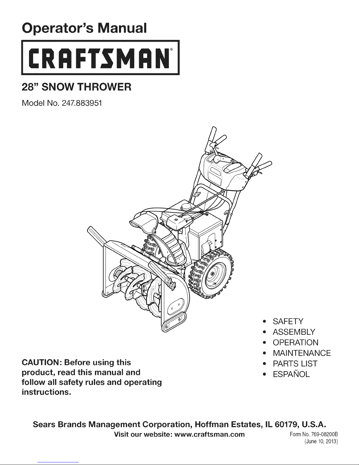
28" SNOW THROWER
Model No. 247.883951
CAUTION" Before using this
product, read this manual and
follow all safety rules and operating
instructions.
Sears Brands Management Corporation, Hoffman Estates, IL 60179, U.S.A.
Visit our website: www.craftsman.com FormI/o 769-08200B
,, SAFETY
o ASSEMBLY
OPERATION
MAINTENANCE
PARTS LIST
o ESPANOL
(June10,2013)
Page 2
WarrantyStatement.............................. Page2
SafeOperationPractices...................... Pages3-6
Assembly.................................... Pages8-13
Operation.................................. Pages14-17
Service&Maintenance....................... Pages18-23
CRAFTSMANTWOYEARFULLWARRANTY
FORTWOYEARSfromthedateofpurchase,thisproductiswarrantedagainstanydefectsinmaterialorworkmanship.Defectiveproductwillreceivefree
repairorfreereplacementif repairisunavailable.
ADDITIONALLIFETIMELIMITEDWARRANTYon UPPERandLOWERCHUTE
FORASLONGASITISUSEDbytheoriginalownerafterthesecondyearfromthedateofpurchase,theupperandlowerchuteofthissnowthrowerare
warrantedagainstanydefectsinmaterialorworkmanshipasverifiedbyaSearsauthorizedserviceprovider.Withproofofpurchase,youwill receiveanew
chutefreeofcharge.Youareresponsibleforthelaborcostofinstallationandanycostincurredtoverifythedefect.
Forwarrantycoveragedetailstoobtainrepairorreplacement,visitthewebsite:www.craftsman.com
ThiswarrantycoversONLYdefectsinmaterialandworkmanship.WarrantycoveragedoesNOTinclude:
• Expendableitemsthatcanwearoutfromnormalusewithinthewarrantyperiod,includingbutnotlimitedto augers,augerpaddles,driftcutters,skid
shoes,shaveplate,shearpins,sparkplug,aircleaner,belts,andoilfilter.
Off-SeasonStorage............................. Page24
Troubleshooting............................... Page26
PartsList................................... Pages28-44
RepairProtectionAgreement.................... Page47
Espa_ol........................................ Page48
• Standardmaintenanceservicing,oilchanges,ortune-ups.
• Tirereplacementorrepaircausedbypuncturesfromoutsideobjects,suchasnails,thorns,stumps,orglass.
• Tireorwheelreplacementorrepairresultingfromnormalwear,accident,orimproperoperationormaintenance.
• Repairsnecessarybecauseofoperatorabuse,includingbutnotlimitedto damagecausedbyover-speedingtheengine,orfromimpactingobjectsthat
bendtheframe,augershaft,etc.
• Repairsnecessarybecauseofoperatornegligence,includingbutnotlimitedto,electricalandmechanicaldamagecausedbyimproperstorage,failureto
usethepropergradeandamountofengineoil,orfailuretomaintaintheequipmentaccordingtotheinstructionscontainedintheoperator'smanual.
• Engine(fuelsystem)cleaningorrepairscausedbyfueldeterminedtobecontaminatedoroxidized(stale).Ingeneral,fuelshouldbeusedwithin30days
ofitspurchasedate.
• Normaldeteriorationandwearoftheexteriorfinishes,orproductlabelreplacement.
Thiswarrantyisvoidifthisproductiseverusedwhileprovidingcommercialservicesorifrentedto anotherperson.
Thiswarrantygivesyouspecificlegalrights,andyoumayalsohaveotherrightswhichvaryfromstatetostate.
SearsBrandsManagementCorporation,NoffmanEstates,IL60179
Engine Oil: 5W-30
Fuel: Unleaded Gasoline
Engine: MTD
Model Number
Serial Number
Date of Purchase
Record the model number, serial number,
and date of purchase above.
© Sears Brands, LLC 2
Page 3
Thissymbolpointsout importantsafetyinstructionswhich, ifnot
followed,couldendangerthe personalsafetyand/orproperty of
yourselfandothers.Readandfollow all instructionsinthis manual
beforeattempting to operatethis machine.Failureto complywith these
instructionsmayresultinpersonalinjury.Whenyouseethis symbol, HEED
ITSWARNING!
Thismachinewasbuilt to beoperatedaccordingtothesafeoperation
practicesinthismanual.Aswith anytype of powerequipment,
carelessnessorerroronthe part ofthe operatorcanresultinseriousinjury.
Thismachineiscapableof amputating fingers, hands,toesandfeet and
throwingdebris.Failuretoobservethefollowing safety instructionscould
resultinseriousinjuryordeath.
CALIFORNIA PROPOSITION 65
EngineExhaust,someofits constituents,andcertainvehiclecomponents
containor emit chemicalsknowntoStateof Californiato causecancerand
birth defectsorother reproductiveharm.
TRAINING
Read,understand,andfollowall instructionsonthemachineandinthe
manual(s)beforeattemptingtoassembleandoperate.Failuretodosocan
resultinseriousinjurytotheoperatorand/orbystanders.Keepthis manual
inasafeplaceforfutureandregularreferenceandfororderingreplacement
parts.
Befamiliarwith allcontrolsandtheirproperoperation.Knowhowto stop
themachineanddisengagethemquickly.
Neverallowchildrenunder14yearsof agetooperatethismachine.Children
14andovershouldreadandunderstandtheinstructionsandsafeoperation
practicesinthismanualandonthemachineandbetrainedandsupervised
byanadult.
Neverallowadultsto operatethismachinewithoutproperinstruction.
Thrownobjectscancauseseriouspersonalinjury.Planyoursnow-throwing
patterntoavoiddischargeofmaterialtowardroads,bystandersandthelike.
Keepbystanders,petsandchildrenatleast75feetfromthemachinewhileit
isin operation.Stopmachineif anyoneentersthearea.
Exercisecautiontoavoidslippingorfalling,especiallywhenoperatingin
reverse.
PREPARATION
Thoroughlyinspecttheareawheretheequipmentistobeused.Removeall
doormats,newspapers,sleds,boards,wiresandotherforeignobjects,which
couldbetrippedoverorthrownbytheauger/impeller.
Alwayswearsafetyglassesoreyeshieldsduringoperationandwhile
performinganadjustmentor repairto protectyoureyes.Thrownobjects
whichricochetcancauseseriousinjurytotheeyes.
Donotoperatewithout wearingadequatewinteroutergarments.Donot
wearjewelry,longscarvesorotherlooseclothing,whichcouldbecome
entangledinmovingparts.Wearfootwearwhichwill improvefootingon
slipperysurfaces.
Useagroundedthree-wireextensioncordandreceptacleforallmachines
with electricstartengines.
Your Responsibility--Restrict theuseof this powermachineto
personswhoread,understandandfollow the warningsand instructionsin
thismanualandonthe machine.
SAVETHESEINSTRUCTIONS!
Disengageallcontrolleversbeforestartingtheengine.
Adjustcollectorhousingheighttocleargravelorcrushedrocksurfaces.
Neverattempttomakeanyadjustmentswhileengineisrunning,except
wherespecificallyrecommendedintheoperator'smanual.
Letengineandmachineadjusttooutdoortemperaturebeforestartingto
clearsnow.
Safe Handling of Gasoline:
Toavoidpersonalinjuryor property damageuseextremecareinhandling
gasoline.Gasolineisextremely flammableandthevaporsareexplosive.
Seriouspersonalinjurycanoccurwhengasolineisspilledon yourselforyour
clotheswhichcanignite.Washyourskinandchangeclothesimmediately.
Useonlyanapprovedgasolinecontainer.
Neverfill containersinsideavehicleoronatruckortrailerbedwitha plastic
liner.Alwaysplacecontainersonthegroundawayfromyourvehiclebefore
filling.
Whenpractical,removegas-poweredequipmentfromthetruckor
trailerandrefuelitontheground.Ifthisis notpossible,thenrefuelsuch
equipmentonatrailerwith aportablecontainer,ratherthanfromagasoline
dispensernozzle.
Keepthenozzleincontactwith therimofthefueltankorcontaineropening
atalltimesuntilfuelingiscomplete.Donotusea nozzlelock-opendevice.
Extinguishallcigarettes,cigars,pipesandothersourcesofignition.
Neverfuelmachineindoors.
Neverremovegascaporaddfuelwhiletheengineishotorrunning.Allow
enginetocoolatleasttwominutesbeforerefueling.
Neveroverfill fueltank.Filltankto nomorethan1/2inchbelowbottomof
fillernecktoallowspacefor fuelexpansion.
Replacegasolinecapandtightensecurely.
Ifgasolineisspilled,wipeit offthe engineandequipment.Moveunitto
anotherarea.Wait.5minutesbeforestartingtheengine.
Page 4
Toreducefirehazards,keepmachinefreeofgrass,leaves,orotherdebris
build-up.Cleanupoilorfuelspillageandremoveanyfuelsoakeddebris.
Neverstorethemachineorfuelcontainerinsidewherethereisanopen
flame,sparkorpilotlightasonawaterheater,spaceheater,furnace,clothes
dryerorothergasappliances.
OPERATION
Donotputhandsorfeetnearrotatingparts,intheauger/impellerhousing
orchuteassembly.Contactwith therotatingpartscanamputatehandsand
feet.
Theauger/impellercontrolleverisasafetydevice.Neverbypassits
operation.Doingsomakesthemachineunsafeandmaycausepersonal
injury.
Thecontrolleversmustoperateeasilyin bothdirectionsandautomatically
returntothedisengagedpositionwhenreleased.
Neveroperatewith amissingordamagedchuteassembly.Keepallsafety
devicesinplaceandworking.
Neverrunanengineindoorsor inapoorlyventilatedarea.Engineexhaust
containscarbonmonoxide,anodorlessanddeadlygas.
Donotoperatemachinewhileundertheinfluenceofalcoholordrugs.
Mufflerandenginebecomehotandcancauseaburn.Donottouch.Keep
childrenaway.
Exerciseextremecautionwhenoperatingonorcrossinggravelsurfaces.Stay
alertforhiddenhazardsortraffic.
Exercisecautionwhenchangingdirectionandwhileoperatingonslopes.Do
notoperateonsteepslopes.
Planyoursnow-throwingpatterntoavoiddischargetowardswindows,
walls,carsetc.Thus,avoidingpossiblepropertydamageorpersonalinjury
causedbyaricochet.
Neverdirectdischargeatchildren,bystandersandpetsor allowanyonein
frontofthemachine.
Donotoverloadmachinecapacitybyattemptingtoclearsnowattoofastof
arate.
Neveroperatethismachinewithoutgoodvisibilityorlight.Alwaysbesureof
yourfootingandkeepafirmholdonthehandles.Walk,neverrun.
Disengagepowertotheauger/impellerwhentransportingornotin use.
Neveroperatemachineathightransportspeedsonslipperysurfaces.Look
downandbehindandusecarewhenbackingup.
Ifthemachineshouldstartto vibrateabnormally,stoptheengine,
disconnectthesparkplugwireandgrounditagainsttheengine.Inspect
thoroughlyfordamage.Repairanydamagebeforestartingandoperating.
Disengageallcontrolleversandstopenginebeforeyouleavetheoperating
position(behindthehandles).Waituntil theauger/impellercomesto
acompletestopbeforeuncloggingthechuteassembly,makingany
adjustments,orinspections.
Neverputyourhandin thedischargeorcollectoropenings.Donotunclog
chuteassemblywhileengineisrunning.Shutoff engineandremainbehind
handlesuntilallmovingpartshavestoppedbeforeunclogging.
Useonlyattachmentsandaccessoriesapprovedbythemanufacturer(e.g.
wheelweights,tirechains,cabsetc.).
Whenstartingengine,pull cordslowlyuntil resistanceisfelt,thenpull
rapidly.Rapidretractionofstartercord(kickback)will pullhandandarm
towardenginefasterthanyoucanletgo.Brokenbones,fractures,bruisesor
sprainscouldresult.
Ifsituationsoccurwhicharenotcoveredinthismanual,usecareandgood
judgment.
CLEARING A CLOGGED DISCHARGE CHUTE
Handcontactwith therotatingimpellerinsidethedischargechuteisthemost
commoncauseofinjuryassociatedwith snowthrowers.Neveruseyourhandto
cleanoutthedischargechute.
Toclearthechute:
a. SHUTTHEENGINEOFF!
b. Wait10secondsto besuretheimpellerbladeshavestopped
rotating.
c. Alwaysuseaclean-outtool,notyourhands.
MAINTENANCE & STORAGE
Nevertamperwith safetydevices.Checktheirproperoperationregularly.
Referto themaintenanceandadjustmentsectionsof thismanual.
Beforecleaning,repairing,orinspectingmachinedisengageallcontrol
leversandstoptheengine.Waituntiltheauger/impellercometoacomplete
stop.Disconnectthesparkplugwireandgroundagainsttheengineto
preventunintendedstarting.
Checkboltsandscrewsforpropertightnessatfrequentintervalsto keepthe
machineinsafeworkingcondition.Also,visuallyinspectmachineforany
damage.
Donotchangetheenginegovernorsettingorover-speedtheengine.The
governorcontrolsthemaximumsafeoperatingspeedof theengine.
Snowthrowershaveplatesandskidshoesaresubjecttowearanddamage.
Foryoursafetyprotection,frequentlycheckallcomponentsandreplace
with originalequipmentmanufacturer's(OEM)partsonlyaslistedinthe
Partspagesofthisoperator'smanual.Useofpartswhichdonotmeetthe
originalequipmentspecificationsmayleadtoimproperperformanceand
compromisesafety!
Checkcontrolleversperiodicallyto verifytheyengageanddisengage
properlyandadjust,if necessary.Referto theadjustmentsectioninthis
operator'smanualforinstructions.
Maintainorreplacesafetyandinstructionlabels,asnecessary.
Observeproperdisposallawsandregulationsforgas,oil,etc.toprotectthe
environment.
Priortostoring,runmachineafewminutestoclearsnowfrommachineand
preventfreezeupof auger/impeller.
Neverstorethemachineorfuelcontainerinsidewherethereisanopen
flame,sparkorpilotlight suchasawaterheater,furnace,clothesdryeretc.
Alwaysrefertotheoperator'smanualforproperinstructionsonoff-season
storage.
4
Page 5
Checkfuelline,tank,cap,andfittingsfrequentlyfor cracksor leaks.Replace
if necessary.
Donotcrankenginewith sparkplugremoved.
AccordingtotheConsumerProductsSafetyCommission(CPSC)andthe
U.S.EnvironmentalProtectionAgency(EPA),thisproducthasanAverage
Useful Lifeofseven(7)years,or60 hoursofoperation.Attheendof
theAverage Useful Lifehavethemachineinspectedannuallybyan
authorizedservicedealerto ensurethat allmechanicalandsafetysystems
areworkingproperlyandnotwornexcessively.Failuretodosocanresultin
accidents,injuriesordeath.
DO NOT MODIFY ENGINE
Toavoidseriousinjuryordeath,donotmodifyengineinanyway. Tampering
with the governorsetting canleadto arunawayengineandcauseit to
operateat unsafespeeds.Nevertamperwith factorysetting ofengine
governor.
NOTICE REGARDING EMiSSiONS
Engineswhichare certifiedto complywith CaliforniaandfederalEPA
emissionregulationsfor SORE(SmallOff RoadEquipment)arecertified
tooperateonregularunleadedgasoline,and mayincludethefollowing
emissioncontrolsystems:EngineModification (EM),OxidizingCatalyst(0C),
SecondaryAirinjection(SAI)andThreeWayCatalyst(TWC)ifsoequipped.
SPARK ARRESTOR
e
Thismachineisequippedwith aninternalcombustionengineandshould
not beusedonornearanyunimprovedforest-covered,brushcoveredor
grass-coveredland unlesstheengine'sexhaustsystemisequippedwith a
sparkarrestormeetingapplicablelocalorstatelaws(if any).
Ira sparkarrestorisused,it shouldbemaintainedineffective working order
bythe operator.IntheStateof Californiathe aboveisrequiredbylaw (Section
4442ofthe CaliforniaPublicResourcesCode).Otherstatesmayhavesimilar
laws.Federallawsapplyonfederal lands.
Asparkarrestorfor the muffler is availablethroughyour nearestSearsParts
andRepairServiceCenter.
Page 6
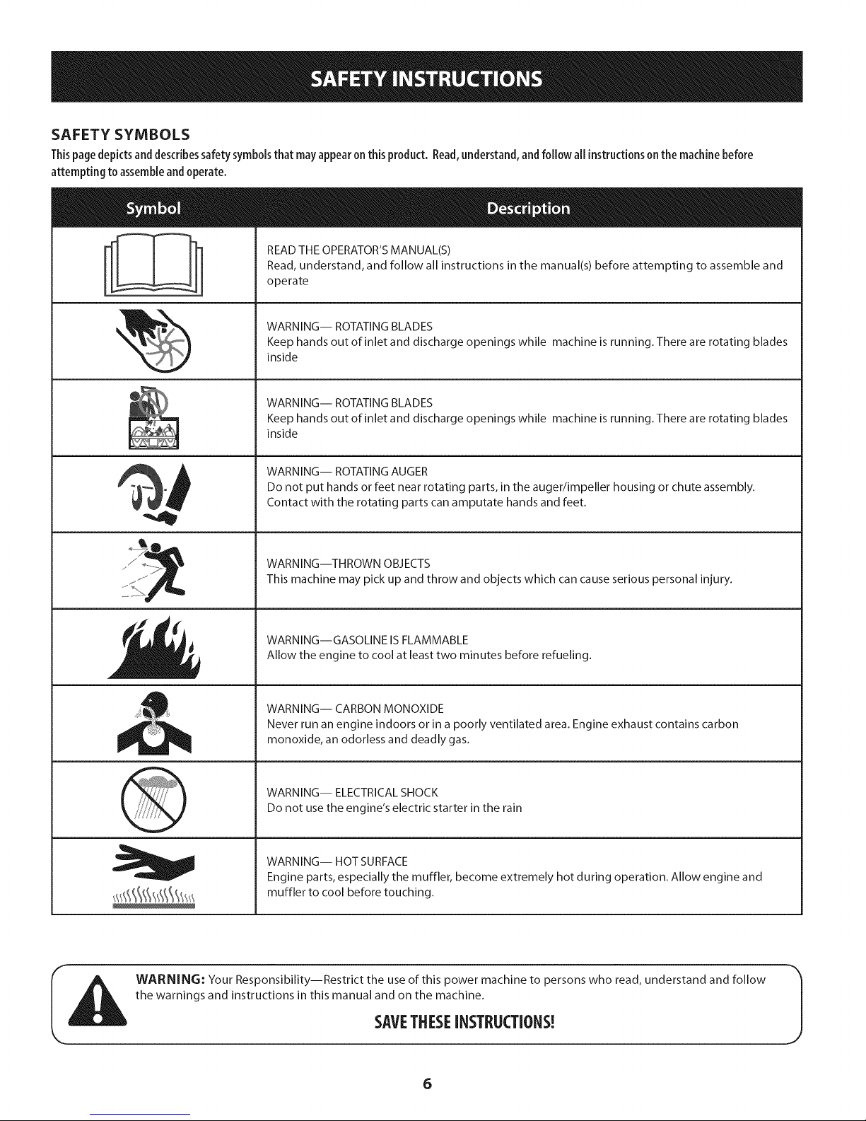
SAFETY SYMBOLS
Thispage depicts and describes safety symbols that may appear on this product. Read, understand, and follow all instructions on the machine before
attempting to assemble and operate.
READ THE OPERATOR'S MANUAL(S)
Read, understand, and follow all instructions in the manual(s) before attempting to assemble and
operate
WARNING-- ROTATING BLADES
Keep hands out of inlet and discharge openings while machine is running. There are rotating blades
inside
WARNING-- ROTATING BLADES
Keep hands out of inlet and discharge openings while machine is running. There are rotating blades
inside
WARNING-- ROTATING AUGER
Do not put hands or feet near rotating parts, in the auger/impeller housing or chute assembly.
Contact with the rotating parts can amputate hands and feet.
WARNING--THROWN OBJECTS
This machine may pick up and throw and objects which can cause serious personal injury.
WARNING--GASOLINE IS FLAMMABLE
Allow the engine to cool at least two minutes before refueling.
WARNING-- CARBON MONOXIDE
Never run an engine indoors or in a poorly ventilated area. Engine exhaust contains carbon
monoxide, an odorless and deadly gas.
WARNING-- ELECTRICAL SHOCK
Do not use the engine's electric starter in the rain
WARNING-- HOT SURFACE
Engine parts, especially the muffler, become extremely hot during operation. Allow engine and
muffler to cool before touching.
WARNING: Your Responsibility--Restrict the use of this power machine to persons who read, understand and follow
the warnings and instructions in this manual and on the machine.
SAVETHESEiNSTRUCTIONS!
6
Page 7

This page left intentionallyblank.
7
Page 8
NOTE:Referencestorightorleftsideofthesnowthroweraredeterminedfrom
behindtheunitin theoperatingposition(standingdirectlybehindthesnow
thrower,facingthehandlepanel).
Removing FromCarton
1. Cutthecornersof thecartonandlaythesidesflatontheground.Remove
anddiscardallpackinginserts.
2. Movethesnowthroweroutofthecarton.
3. Makecertainthecartonhasbeencompletelyemptiedbeforediscardingit.
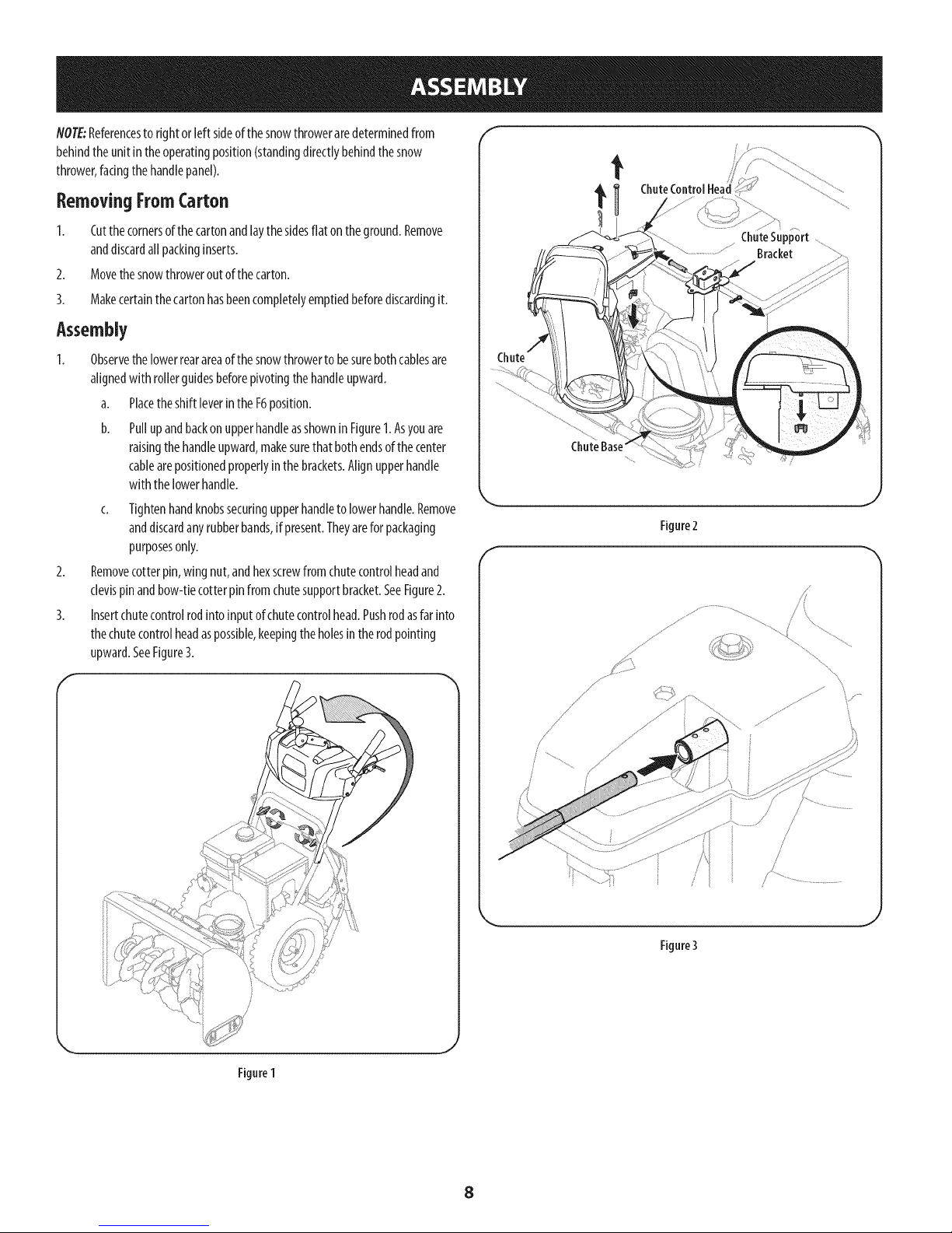
Assembly
Observethelowerrearareaof thesnowthrowerto besurebothcablesare
alignedwith rollerguidesbeforepivotingthehandleupward.
a. Placetheshift [everintheF6position.
b. Pullupandbackonupperhandleasshownin Figure1.Asyouare
raisingthehandleupward,makesurethatbothendsofthecenter
cablearepositionedproperlyinthebrackets.Alignupperhandle
withthelowerhandle.
c. Tightenhandknobssecuringupperhandletolowerhandle.Remove
anddiscardanyrubberbands,if present.Theyarefor packaging
purposesonly.
Removecotterpin,wingnut,andhexscrewfromchutecontrolheadand
clevispinandbow-tiecotterpinfromchutesupportbracket.SeeFigure2.
Insertchutecontrolrodintoinputof chutecontrolhead.Pushrodasfarinto
thechutecontrolheadaspossible,keepingtheholesin therodpointing
upward.SeeFigure3.
f
t
Figure2
f
/ .....
Figure1
j
Rgure3
J
8
Page 9
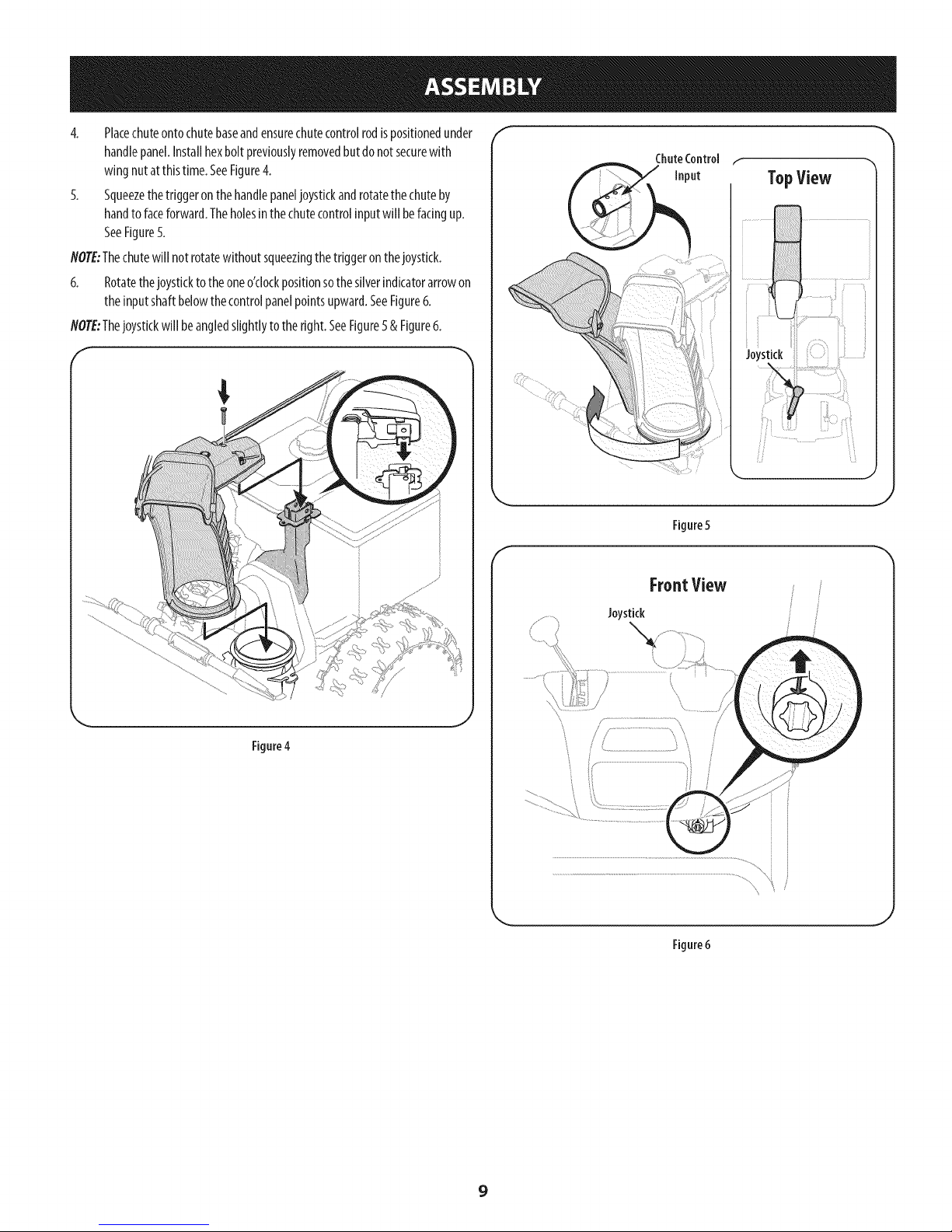
4. Placechuteontochutebaseandensurechutecontrolrodispositionedunder
handlepanel.Installhexboltpreviouslyremovedbutdonotsecurewith
wingnutat thistime.SeeFigure4.
5. Squeezethetriggeronthehandlepaneljoystickandrotatethechuteby
handtofaceforward.Theholesinthechutecontrolinputwillbefacingup.
SeeFigure5.
NOTE:Thechutewillnot rotatewithoutsqueezingthetriggeronthejoystick.
6. Rotatethejoysticktotheoneo'clockpositionsothesliverindicatorarrowon
theinputshaftbelowthecontrolpanelpointsupward.SeeFigure6.
NOTE:Thejoystickwill beangledslightlytotheright.SeeFigure5& Figure6.
f
TopView
Figure5
FrontView
Figure4
//f "_
Joystick
\
Figure6
9
Page 10
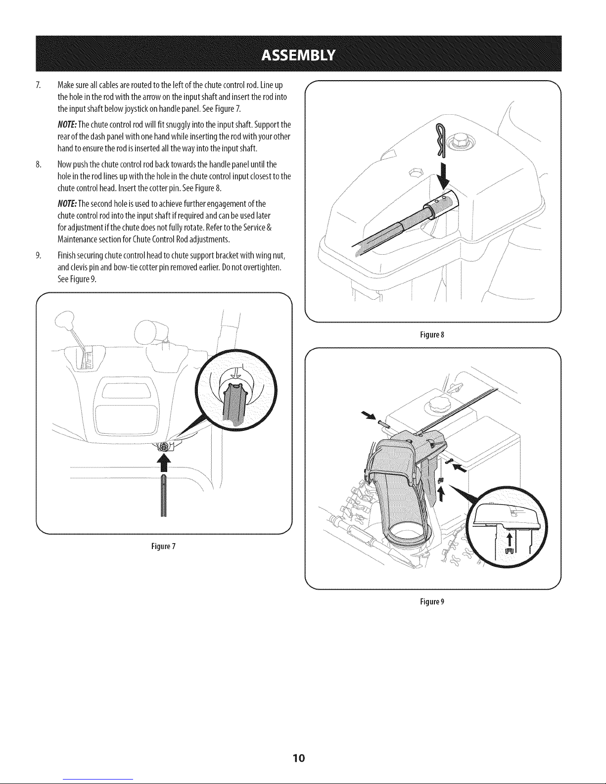
7. Makesureallcablesareroutedtotheleftofthechutecontrolrod.Lineup
theholeintherodwiththearrowontheinputshaftandinserttherodinto
theinputshaftbelowjoystickonhandlepanel.SeeFigure7.
NOTE:Thechutecontrolrodwill fit snugglyintotheinputshaft.Supportthe
rearofthedashpanelwithonehandwhileinsertingtherodwith yourother
handtoensuretherodisinsertedallthewayintotheinputshaft.
8. Nowpushthechutecontrolrodbacktowardsthehandlepaneluntilthe
holeintherodlinesupwith theholeinthechutecontrolinputclosesttothe
chutecontrolhead.Insertthecotterpin.SeeFigure8.
NOTE:Thesecondholeisusedtoachievefurtherengagementof the
chutecontrolrodintotheinputshaftifrequiredandcanbeusedlater
foradjustmentifthechutedoesnotfully rotate.RefertotheService&
Maintenancesectionfor ChuteControlRodadjustments.
9. Finishsecuringchutecontrolheadtochutesupportbracketwithwing nut,
andclevispinandbow-tiecotterpinremovedearlier.Donotovertighten.
SeeFigure9.
f
f
/ /
Figure8
f
Figure7
\
Figure9
10
Page 11
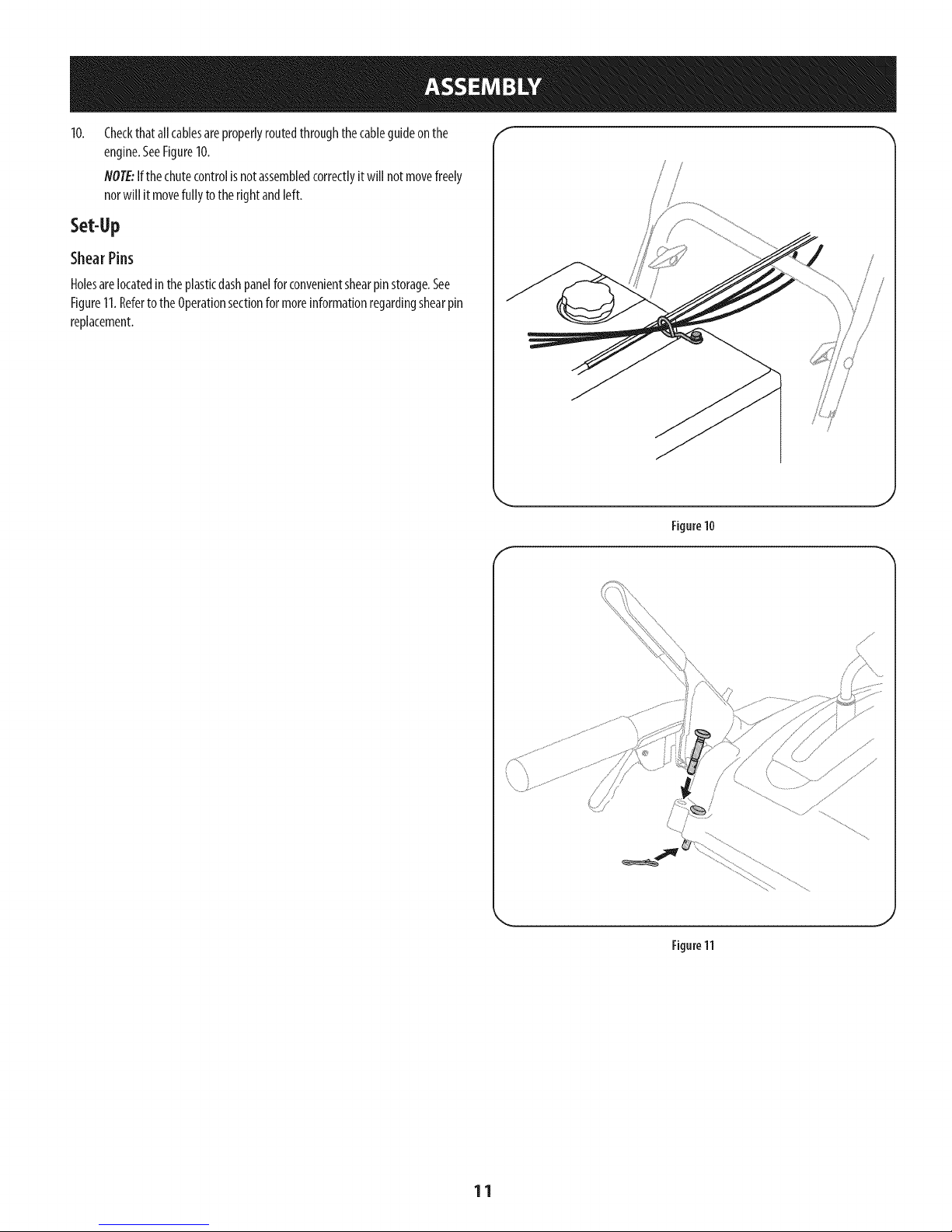
Checkthatallcablesareproperlyroutedthroughthecableguideonthe
engine.SeeFigure10.
NOTE:Ifthechutecontrolisnotassembledcorrectlyitwill notmovefreely
norwill it movefully totherightandleft.
Set-Up
ShearPins
Holesarelocatedintheplasticdashpanelforconvenientshearpinstorage.See
Figure11.RefertotheOperationsectionfor moreinformationregardingshearpin
replacement.
/
; S
J
Figure10
f
J
Figure11
11
Page 12
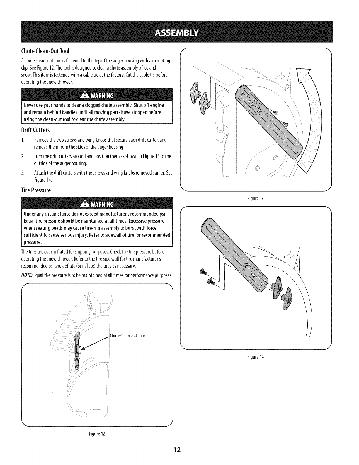
ChuteClean-OutTool _
Achuteclean-outtoolisfastenedtothetopoftheaugerhousingwithamounting
clip.SeeFigure12.Thetoolisdesignedtoclearachuteassemblyoficeand
snow.Thisitemisfastenedwithacabletieat thefactory.Cutthecabletiebefore
operatingthesnowthrower.
Neveruseyour handstoclearacloggedchuteassembly.Shutoff engine
andremainbehindhandlesuntil all movingpartshavestoppedbefore
usingthe clean-outtool to clearthe chuteassembly.
Drift Cutters
1. Removethetwo screwsandwingknobsthatsecureeachdriftcutter,and
removethemfromthesidesoftheaugerhousing.
2. TurnthedriftcuttersaroundandpositionthemasshowninFigure13tothe
outsideoftheaugerhousing.
3. Attachthedriftcutterswiththescrewsandwingknobsremovedearlier.See
Figure14.
TirePressure
Underanycircumstancedo notexceedmanufacturer'srecommendedpsi.
Equaltire pressureshouldbemaintainedat all times.Excessivepressure
when seatingbeadsmaycausetirelrim assemblyto burstwith force
sufficient tocauseseriousinjury. Refertosidewallof tire for recommended
pressure.
Thetiresareover-inflatedforshippingpurposes.Checkthetire pressurebefore
operatingthesnowthrower.Refertothetiresidewallfor tiremanufacturer's
recommendedpsianddeflate(orinflate)thetiresasnecessary.
NOTE:Equaltirepressureisto bemaintainedatalltimesforperformancepurposes.
J
Figure13
ChuteClean-outTool
Figure12
Figure14
J
12
Page 13
Adjustments f
SkidShoes
Thesnowthrowerskidshoesareadjustedupwardatthefactoryforshipping
purposes.Adjustthemdownward,if desired,priorto operatingthesnowthrower.
it isnotrecommendedthatyouoperatethissnowthrower ongravelas
it caneasilypickupandthrowloosegravel,causingpersonalinjuryor
damageto thesnowthrowerandsurroundingproperty.
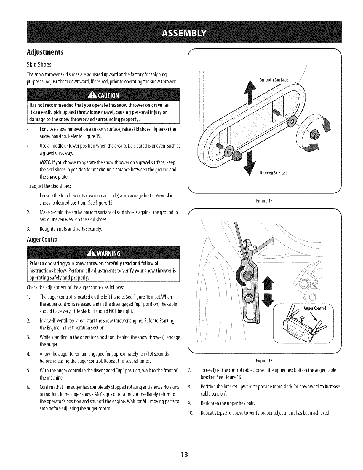
Forclosesnowremovalonasmoothsurface,raiseskidshoeshigheronthe
augerhousing.Referto Figure15.
Useamiddleorlowerpositionwhentheareatobeclearedis uneven,suchas
agraveldriveway.
NOTE:Ifyouchoosetooperatethesnowthrowerona gravelsurface,keep
theskidshoesinpositionformaximumclearancebetweenthegroundand
theshaveplate.
Toadjusttheskidshoes:
1. Loosenthefourhexnuts(twooneachside)andcarriagebolts.Moveskid
shoestodesiredposition.SeeFigure15.
2. Makecertaintheentirebottomsurfaceofskidshoeisagainstthegroundto
avoidunevenwearontheskidshoes.
3. Retightennutsandboltssecurely.
AugerControl
SmoothSurface
UnevenSurface
J
Figure15
Priortooperatingyoursnowthrower,carefullyreadandfollow all
instructionsbelow.Performall adjustmentsto verify yoursnowthroweris
operatingsafelyandproperly.
Checktheadjustmentoftheaugercontrolasfollows:
1. Theaugercontrolislocatedonthelefthandle.SeeFigure16inset.When
theaugercontrolisreleasedandinthedisengaged"up"position,thecable
shouldhaveverylittle slack.ItshouldNOTbetight.
2. Inawell-ventilatedarea,startthesnowthrowerengine.Referto Starting
theEngineintheOperationsection.
3. Whilestandingintheoperator'sposition(behindthesnowthrower),engage
theauger.
4. Allowtheaugerto remainengagedforapproximatelyten(10)seconds
beforereleasingtheaugercontrol.Repeatthisseveraltimes.
5. Withtheaugercontrolin thedisengaged"up" position,walkto thefrontof
themachine.
6.
ConfirmthattheaugerhascompletelystoppedrotatingandshowsNOsigns
ofmotion.IftheaugershowsANYsignsofrotating,immediatelyreturnto
theoperator'spositionandshutofftheengine.WaitforALLmovingpartsto
stopbeforeadjustingtheaugercontrol.
..................................................... ............................
/
/_ AugerControl--
f /,
J
\ J
Figure16
7. Toreadjustthecontrolcable,loosentheupperhexboltontheaugercable
bracket.SeeFigure16.
8. Positionthebracketupwardtoprovidemoreslack(ordownwardtoincrease
cabletension).
9. Retightenthe upperhexbolt.
10. Repeatsteps2-6aboveto verifyproperadjustmenthasbeenachieved.
13
Page 14
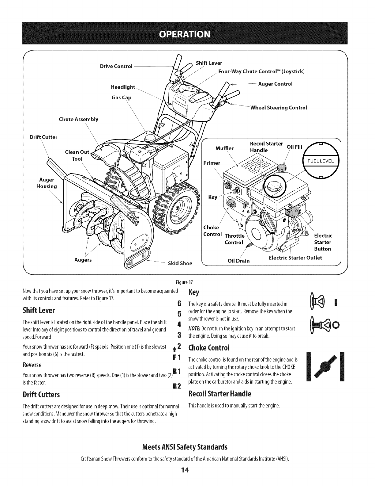
Drive Control
Headlight
Shift Lever
_ Four-Way Chute ControP (Joystick)
Auger Control
Gas C_
Chute Assembly
Drift Cutter
Clean Out
Auger
Hous_
\
Nowthatyouhavesetupyoursnowthrower,it'simportanttobecomeacquainted
with itscontrolsandfeatures.Referto Figure17.
Tool
\
Augers
\
Skid Shoe
Figure17
Shift [ever
Theshift leverislocatedontheright sideofthehandlepanel.Placetheshift
leverintoanyofeightpositionstocontrolthedirectionoftravelandground
speed.Forward
Yoursnowthrowerhassixforward(F)speeds.Positionone(1)isthe slowest
andpositionsix(6)isthefastest.
t 2 ChokeControl
Reverse
Yoursnowthrowerhastwo reverse(R)speeds.One(1)istheslowerandtwo(2)R 1
isthefaster. R2
Drift Cutters
Wheel Steering Control
Recoil Starter
Handle
Choke
Control Throttle
Control
Oil Drain
Oil Fill
Electric Starter Outlet
,ey6 Thekeyisasafetydevice.It mustbefully insertedin Ii
5 orderfortheenginetostart.Removethekeywhenthe
4 NOTE:Donotturntheignitionkeyinanattempttostart
snowthrowerisnotinuse. (_ O
3 theengine.Doingsomaycauseitto break.
activated byturning the rotarychokeknobto the CHOKE
position.Activatingthe choke controlclosesthe choke
plateon the carburetorandaids instarting the engine.
RecoUStarterHandle
Thedrift cuttersaredesignedfor useindeepsnow.Theiruseisoptionalfor normal
snowconditions.Maneuverthesnowthrowersothatthecutterspenetrateahigh
standingsnowdriftto assistsnowfallingintotheaugersforthrowing.
CraftsmanSnowThrowersconformtothesafetystandardoftheAmericanNationalStandardsInstitute(ANSI).
Thishandleisusedtomanuallystarttheengine.
MeetsANSiSafetyStandards
14
Page 15
Throttlecontrol
Thethrottlecontrolislocatedontherearoftheengine.It regulatesthespeedofthe
engineandwillshutoffthe enginewhenmovedintotheSTOPposition.
Primer
Depressingtheprimerforcesfueldirectlyintothe
engine'scarburetortoaidincold-weatherstarting.
ElectricStarter Button
DriveControl/Auger Control Lock
/ DRIVE
CONTROL
Pressingtheelectricstarterbuttonengagestheengine'selectricstarterwhen
pluggedintoa 120Vpowersource.
ElectricStarter Outlet
Requirestheuseofathree-prongoutdoorextensioncordanda 120Vpowersource/
walloutlet.
OilFill
Engineoillevelcanbecheckedandoiladdedthroughtheoil fill.
GasCap
Unthreadthegascaptoaddgasolinetothefueltank.
Auger
Whenengaged,theaugerbladesrotateanddrawsnowintotheaugerhousing.
ChuteAssembly
Snowdrawnintotheaugerhousingisdischargedoutthechuteassembly.
SkidShoes
Positiontheskidshoesbasedonsurfaceconditions.Adjustupwardforhard-packed
snow.Adjustdownwardwhenoperatingongravelorcrushedrocksurfaces.
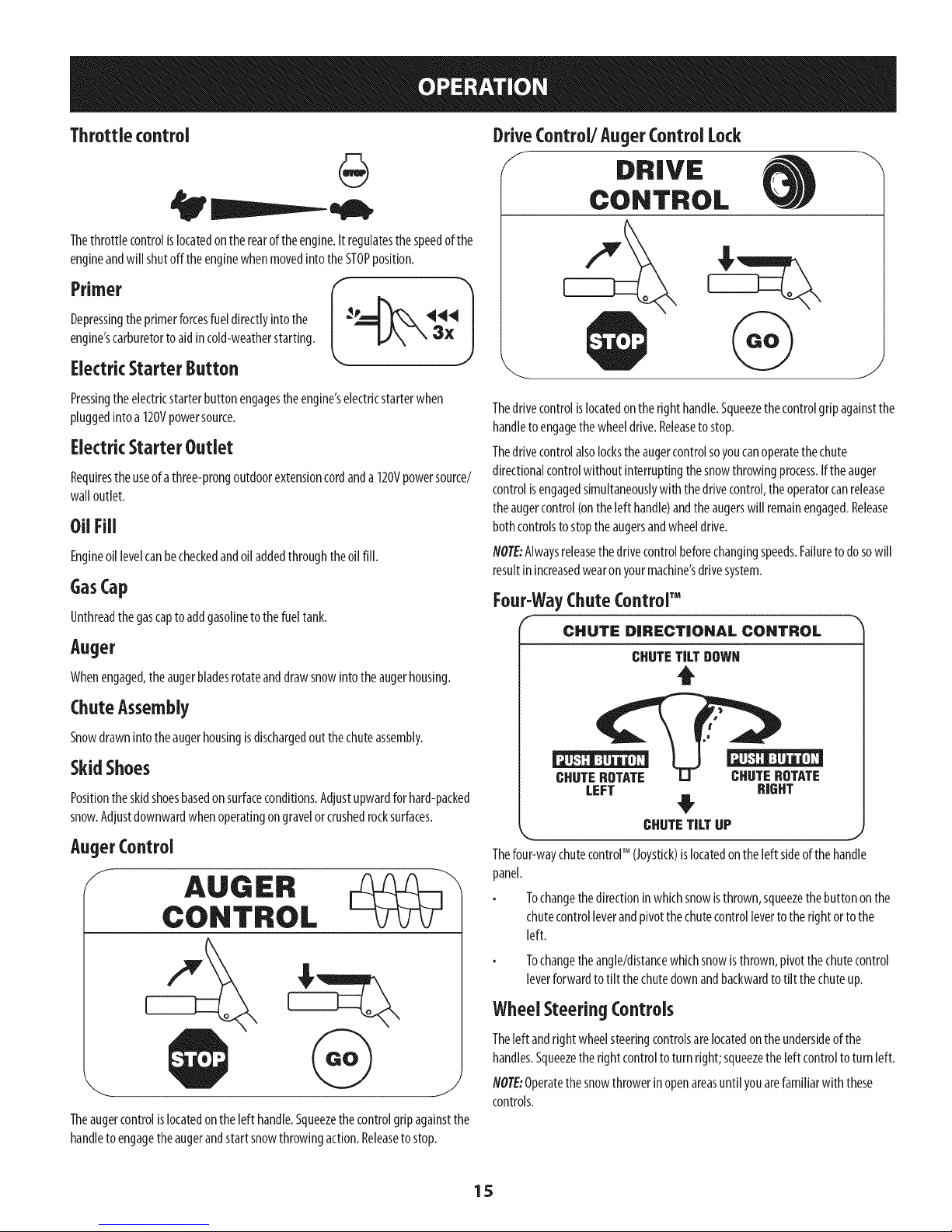
AugerControl
f
Thedrivecontrolislocatedontheright handle.Squeezethecontrolgripagainstthe
handletoengagethewheeldrive.Releasetostop.
Thedrivecontrolalsolockstheaugercontrolsoyoucanoperatethechute
directionalcontrolwithoutinterruptingthesnowthrowingprocess.Iftheauger
controlisengagedsimultaneouslywiththedrivecontrol,theoperatorcanrelease
theaugercontrol(ontheleft handle)andtheaugerswill remainengaged.Release
bothcontrolstostoptheaugersandwheeldrive.
flOTE:Alwaysreleasethedrivecontrolbeforechangingspeeds.Failuretodosowill
resultinincreasedwearonyourmachine'sdrivesystem.
Four-WayChuteControrM
CHUTe: DIRECTIONAL CONTROL
CHUTETILTDOWN
t
CHUTEROTATE CHUTEROTATE
LEFT RIGHT
CHUTETILTUP
_r n_
Thefour-waychutecontrolTM (Joystick)is locatedontheleft sideofthehandle
panel.
Tochangethedirectioninwhichsnowisthrown,squeezethebuttononthe
chutecontrolleverandpivotthechutecontrollevertotherightortothe
left.
Theaugercontrolislocatedontheleft handle.Squeezethecontrolgripagainstthe
handletoengagetheaugerandstartsnowthrowingaction.Releasetostop.
Tochangetheangle/distancewhichsnowisthrown,pivotthechutecontrol
leverforwardtotilt thechutedownandbackwardto tilt thechuteup.
Wheel Steering Controls
Theleft andrightwheelsteeringcontrolsarelocatedontheundersideofthe
handles.Squeezetherightcontroltoturnright;squeezetheleftcontroltoturn left.
NOTE:Operatethesnowthrowerinopenareasuntilyouarefamiliarwith these
controls.
15
Page 16
Clean-OutTool
Neveruseyour handstoclearacloggedchuteassembly.Shutoff engine
andremainbehindhandlesuntilall movingparts havestoppedbefore
usingthe clean-outtool to clearthe chuteassembly.
Thechutedean-outtoolisconvenientlyfastenedtotherearoftheaugerhousing
with amountingclip.Shouldsnowandicebecomelodgedin thechuteassembly
duringoperation,proceedasfollowstosafelycleanthechuteassemblyandchute
opening:
1. ReleaseboththeAugerControlandtheDriveControl.
2. Stoptheenginebyremovingthe ignitionkey.
3. Removetheclean-outtoolfromtheclipwhichsecuresit totherearofthe
augerhousing.
4. Usetheshovel-shapedendoftheclean-outtoolto dislodgeandscoopany
snowandicewhichhasformedinandnearthechuteassembly.
5. Refastentheclean-outtoolto themountingdip ontherearoftheauger
housing,reinserttheignitionkeyandstartthesnowthrower'sengine.
6. Whilestandingintheoperator'sposition(behindthesnowthrower),engage
theaugercontrolforafewsecondstoclearanyremainingsnowandicefrom
thechuteassembly.
BeforeStartingEngine
Read,understand,andfollow all instructionsandwarningsonthe
machineandinthis manualbeforeoperating.
Oil
Theunitwasshippedwithoilintheengine.Checkoillevelbeforeeachoperationto
ensureadequateoilintheengine.
flO?E:Besuretochecktheengineonalevelsurfacewiththeenginestopped.
1. Removetheoilfiller cap/dipstickandwipethedipstickclean.
2. Insertthecap/dipstickintotheoilfiller neck,butdoNOTscrewit in.
3. Removetheoilfiller cap/dipstick.Ifthelevelislow,slowlyaddoil(5W-30,
with aminimumclassificationof SF/SG)untiloillevelregistersbetweenhigh
(H)andlow(L).
flOTE:Donotoverfill.Overfillingwithoilmayresultinenginesmoking,hard
startingorsparkplugfouling.
4.
Replaceandtightencap/dipstickfirmlybeforestartingengine.
Gasoline
Useautomotivegasoline(unleadedorlowleadedto minimizecombustionchamber
deposits)witha minimumof87octane.Gasolinewithupto 10%ethanolor15%
MTBE(MethylTertiaryButylEther)canbeused.Neveruseanoil/gasolinemixture
ordirtygasoline.Avoidgettingdirt, dust,orwaterinthefueltank.DONOTuseE85
gasoline.
Refuelinawell-ventilatedareawith theenginestopped.Donotsmokeor
allowflamesorsparksin theareawheretheengineisrefueledorwhere
gasolineisstored.
Donotoverfillthefueltank.Afterrefueling,makesurethetankcapisclosed
properlyandsecurely.
Becarefulnottospillfuelwhenrefueling.Spilledfuelorfuelvapormay
ignite.Ifanyfuelisspilled,makesuretheareaisdry beforestartingthe
engine.
Avoidrepeatedorprolongedcontactwithskinorbreathingofvapor.
Useextremecarewhenhandlinggasoline.Gasolineisextremely
flammableandthevaporsareexplosive.Neverfuel the machineindoorsor
while the engineishotor running. Extinguishcigarettes,cigars,pipesand
othersourcesof ignition.
1.
Cleanaroundfuelfill beforeremovingcaptofuel.
2.
Afuel levelindicatorislocatedinthefueltank.SeeFigure17inset.Be
carefulnottooverfill.Filltankuntil fuelreachesthefuellevelindicatorto
allowspacefor fuelexpansion.
Starting TheEngine
Alwayskeephandsandfeet clearof movingparts.Donot useapressurized
starting fluid. Vaporsareflammable.
flOTE:Allowtheengineto warmupfor afewminutesafterstarting.Theenginewill
notdevelopfull poweruntilit reachesoperatingtemperatures.
1. Makecertainboththeaugercontrolanddrivecontrolarein thedisengaged
(released)position.
2. Insertkeyintoslot.Makesureit snapsintoplace.Donotattempttoturn the
key.
NOTE:Theenginecannotstartwithoutthekeyfullyinsertedinto the
ignitionswitch.
ElectricStarter
Theelectric starterisequippedwith agroundedthree-wirepower plug,
andisdesignedtooperateon 120voltAChouseholdcurrent.It must be
usedwith aproperlygroundedthree-prongreceptacleatall timesto avoid
the possibilityof electrk shock.Followall instructionscarefullypriorto
operatingthe electricstarter. DONOTuseelectric starter inthe rain.
Determinethatyourhome'swring isathree-wiregroundedsystem.Askalicensed
electricianifyouarenotcertain.
Ifyouhavea groundedthree-prongreceptacle,proceedasfollows.Ifyoudonot
havetheproperhousewiring,DONOTusetheelectricstarterunderanyconditions.
1. Pluganextensioncordintotheoutletlocatedontheengine'ssurface.Plug
theotherendofextensioncordintoathree-prong120-volt,grounded,AC
outletinawell-ventilatedarea.
Theextensioncordcan beanylength, but must beratedfor 15ampsat
125volts,groundedand ratedforoutdoor use.
16
Page 17
2. MovethrottlecontroltoFAST(rabbit)_Jl__ position.
3 MovechoketotheCHOKEI,'Ipos t on co,deng nestart),fengine s
warm,placechokein RUNposition.
4. Pushprimerthree(3)times,makingsuretocoverventholeinprimerbulb
whenpushing.Ifengineiswarm,pushprimeronlyonce.Alwayscovervent
holewhenpushing.Coolweathermayrequireprimingto berepeated.
5. Pushstarterbuttonto startengine.Oncetheenginestarts,immediately
releasestarterbutton.Electricstarterisequippedwith thermaloverload
protection;systemwilltemporarilyshut-downtoallowstartertocoolif
electricstarterbecomesoverloaded.
6.
Astheenginewarms,slowlyrotatethechokecontroltoRUNposition.Ifthe
enginefalters,restartengineandrunwith chokeathalf-chokepositionfora
shortperiodoftime,andthenslowlyrotatethechokeinto RUNposition.
Afterengineisrunning,disconnectpowercordfromelectricstarter.When
disconnecting,alwaysunplugtheendatthewalloutletbeforeunplugging
theoppositeendfromtheengine.
RecoilStarter
ToEngageDrive
1. Withthethrottlecontrolinthe Fast(rabbit)_ _1 position,moveshiftlever
intooneofthesixforward(F)positionsortwo reverse(R)positions.Selecta
speedappropriatefor thesnowconditionsanda paceyou'recomfortable
with.
NOTE:WhenselectingaDriveSpeed,usetheslowerspeedsuntilyouare
comfortableandfamiliarwiththeoperationofthesnowthrower.
2. Squeezethedrivecontrolagainstthehandleandthesnowthrowerwill
move.Releaseit anddrivemotionwillstop.
NOTE:NEVERrepositiontheshiftlever(changespeedsordirectionoftravel)
withoutfirst releasingthedrivecontrolandbringingthesnowthrowertoa
completestop.Doingsowillresultinprematureweartothesnowthrower'sdrive
system.
ToEngageAuger
Toengagetheaugerandstartthrowingsnow,squeezetheaugercontrol
againstthelefthandle.Releaseto stoptheauger.
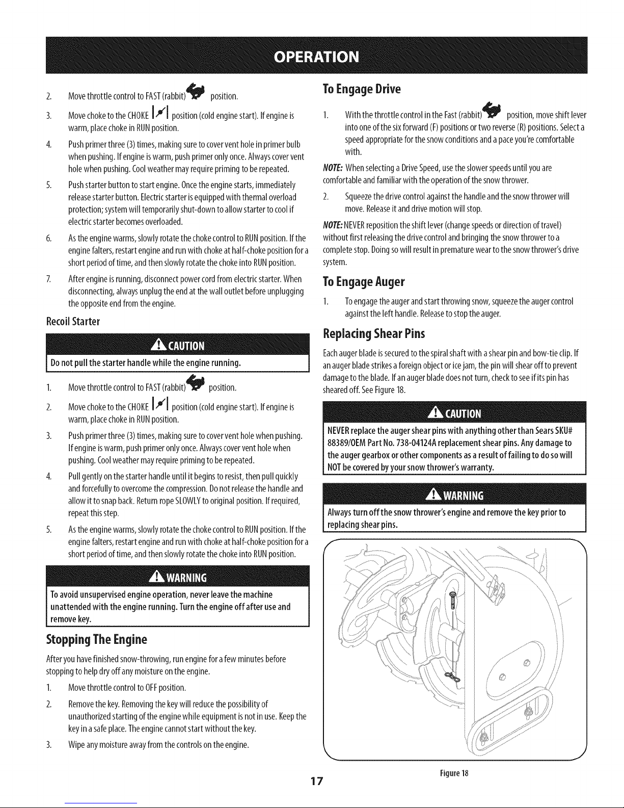
ReplacingShearPins
Eachaugerbladeissecuredtothespiralshaftwithashearpinandbow-tieclip.If
Donotpull the starter handlewhilethe enginerunning.
1. MovethrottlecontroltoFAST(rabbit)_ _j position.
2. MovechoketotheCHOKEI,.'1position(coldenginestart).If engineis
warm,placechokein RUNposition.
3. Pushprimerthree(3)times,makingsuretocoverventholewhenpushing.
Ifengineiswarm,pushprimeronlyonce.Alwayscoverventholewhen
pushing.Coolweathermayrequireprimingtoberepeated.
4. Pullgentlyonthestarterhandleuntilit beginsto resist,thenpullquickly
andforcefullytoovercomethecompression.Donotreleasethe handleand
allowit tosnapback.ReturnropeSLOWLYto originalposition.If required,
repeatthisstep.
5. Astheenginewarms,slowlyrotatethechokecontrolto RUNposition.Ifthe
enginefalters,restartengineandrunwith chokeathalf-chokepositionfora
shortperiodoftime,andthenslowlyrotatethechokeinto RUNposition.
anaugerbladestrikesaforeignobjectoricejam,thepinwill shearoff toprevent
damagetotheblade.Ifanaugerbladedoesnotturn,checktoseeif itspinhas
shearedoff. SeeFigure18.
NEVERreplacethe augershearpinswith anything otherthan SearsSKU#
88389/0EMPartNo.738-04124Areplacementshearpins.Anydamageto
the augergearboxorother componentsasaresultof failing to dosowill
NOTbecoveredbyyoursnowthrower'swarranty.
Alwaysturn off the snowthrower'sengineandremovethekeypriorto
replacingshearpins.
Toavoidunsupervisedengineoperation,neverleavethe machine
unattendedwith theenginerunning. Turnthe engineoff after useand
removekey.
Stopping TheEngine
Afteryouhavefinishedsnow-throwing,runengineforafewminutesbefore
stoppingto helpdryoffanymoistureontheengine.
1. MovethrottlecontroltoOFFposition.
2. Removethekey.Removingthe keywill reducethepossibilityof
unauthorizedstartingoftheenginewhileequipmentisnotinuse.Keepthe
keyina safeplace.Theenginecannotstartwithoutthekey.
3. Wipeanymoistureawayfromthecontrolsontheengine.
17
Figure18
Page 18
MAINTENANCESCHEDULE
Beforeperforminganytypeof maintenance/service,disengageallcontrols
andstopthe engine.Waituntil all moving partshavecometo a complete
stop.Disconnectsparkplug wireand grounditagainsttheengineto
preventunintendedstarting.
Followthemaintenanceschedulegivenbelow.Thischartdescribesservice
guidelinesonly.UsetheServiceLogcolumntokeeptrackofcompleted
maintenancetasks.TolocatethenearestSearsServiceCenterorto scheduleservice,
simplycontactSearsat1-800-4-MY-HOME®.
EachUseandevery5hours
Ist5hours
Annuallyor25hours
Annuallyor50hours
Annuallyor100hours
BeforeStorage
1. Engineoil level
2. Looseormissinghardware
3. Unitandengine.
1. Engineoil
1. Sparkplug
2. Controllinkagesandpivots
3. Wheels
4. GearshaftandAugershaft
5. 4-WayChuteControlTM
1. Engineoil
1. Sparkplug
1. Fuelsystem
GENERALRECOMMENDATIONS
CheckingEngineOil
Beforelubricating, repairing,or inspecting,disengageall controlsandstop
engine.Waituntil all movingparts havecometo acompletestop.
NOTE:Checktheoillevelbeforeeachuseto besurecorrectoillevelismaintained.
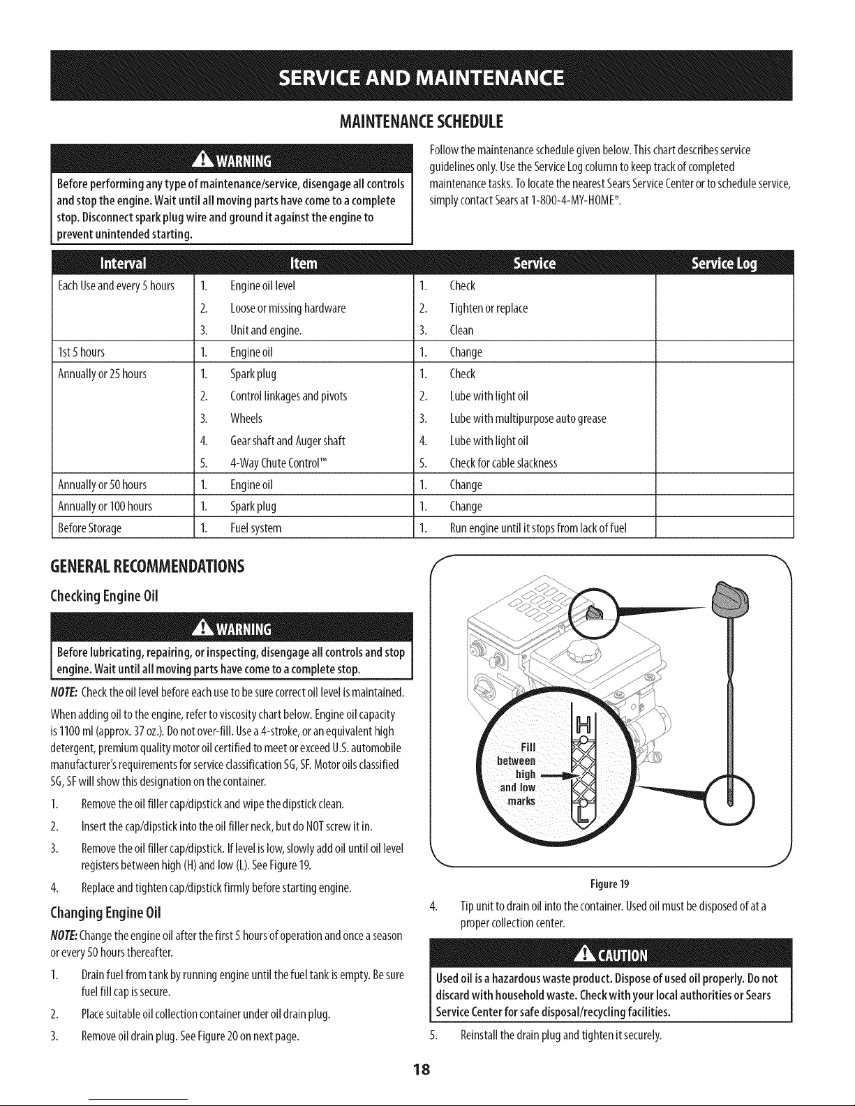
Whenaddingoiltotheengine,refertoviscositychartbelow.Engineoilcapacity
is1100ml(approx.37oz.).Donotover-fill.Usea4-stroke,oranequivalenthigh
detergent,premiumqualitymotoroilcertifiedtomeetorexceedU.S.automobile
manufacturer'srequirementsforserviceclassificationSG,SF.Motoroilsclassified
SG,SFwillshowthisdesignationonthecontainer.
1. Removetheoilfiller cap/dipstkkandwipethedipstickclean.
2. Insertthecap/dipstickintotheoilfillerneck,butdoNOTscrewit in.
3. Removetheoilfiller cap/dipstick.Iflevelislow,slowlyaddoiluntiloillevel
registersbetweenhigh(H)andlow(L).SeeFigure19.
4. Replaceandtightencap/dipstickfirmlybeforestartingengine.
ChangingEngineOil
NOTE:Changetheengineoilafterthefirst5 hoursofoperationandoncea season
orevery50hoursthereafter.
1. Drainfuelfromtankbyrunningengineuntilthefueltankisempty.Besure
fuelfill capissecure.
2. Placesuitableoilcollectioncontainerunderoil drainplug.
3. Removeoildrainplug.SeeFigure20onnextpage.
1. Check
2. Tightenorreplace
3. Clean
1. Change
1. Check
2. Lubewithlightoil
3. Lubewithmultipurposeautogrease
4. Lubewithlightoil
5. Checkforcableslackness
1. Change
1. Change
1. Runengineuntilitstopsfromlackoffuel
f
J
Figure19
Tipunittodrainoil intothecontainer.Usedoil mustbedisposedof ata
propercollectioncenter.
Usedoil isahazardouswasteproduct.Disposeofusedoil properly.Donot
discardwith householdwaste.Checkwithyour localauthorities or Sears
ServiceCenterforsafedisposal/recyclingfacilities.
5. Reinstallthedrainplugandtightenitsecurely.
18
Page 19
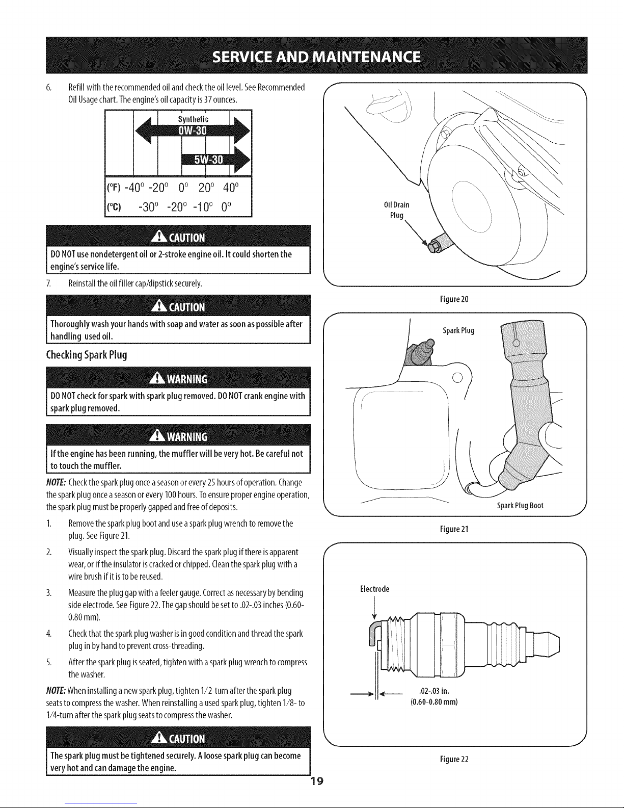
Refillwith therecommendedoilandchecktheoil level.SeeRecommended
OilUsagechart.Theengine'soilcapacityis37ounces.
(oF)-40o-20 o 0o 200 400
(oc) -30° -20° -10° 0°
DONOTusenondetergentoil or 2-strokeengineoil. It couldshortenthe
engine'sservicelife.
7. Reinstalltheoilfillercap/dipsticksecurely.
Thoroughlywashyourhandswith soapandwaterassoonaspossibleafter
handling usedoil.
CheckingSparkPlug
OilDrain
Plug \
Figure20
E
SparkPlug
DONOTcheckforsparkwith sparkplugremoved.DONOTcrankenginewith
sparkplug removed.
Ifthe enginehasbeenrunning,the muffler will beveryhot. Becarefulnot
to touchthe muffler.
NOTE:Checkthe sparkplugonceaseasonor every25hoursofoperation.Change
thesparkplugonceaseasonorevery100hours.Toensureproperengineoperation,
thesparkplugmustbeproperlygappedandfreeofdeposits.
1. Removethesparkplugbootandusea sparkplugwrenchtoremovethe
plug.SeeFigure21.
2. Visuallyinspectthesparkplug.Discardthesparkplugifthereisapparent
wear,orif theinsulatoriscrackedorchipped.Cleanthesparkplugwitha
wirebrushifit istobereused.
3.
Measurethepluggapwith afeelergauge.Correctasnecessarybybending
sideelectrode.SeeFigure22.Thegapshouldbesetto.02-.03inches(0.60-
0.80mm).
4. Checkthatthesparkplugwasherisin goodconditionandthreadthespark
pluginbyhandtopreventcross-threading.
5. Afterthesparkplugisseated,tightenwithasparkplugwrenchtocompress
thewasher.
NOTE:Wheninstallinganewsparkplug,tighten1/2-turnafterthesparkplug
seatstocompressthewasher.Whenreinstallingausedsparkplug,tighten1/8-to
1/4-turnafterthesparkplugseatsto compressthewasher.
SparkPlugBoot
Figure21
Electrode
Thesparkplug mustbetightened securely.Aloosesparkplugcanbecome
very hotandcandamagethe engine.
Figure22
19
Page 20
Lubrication "I
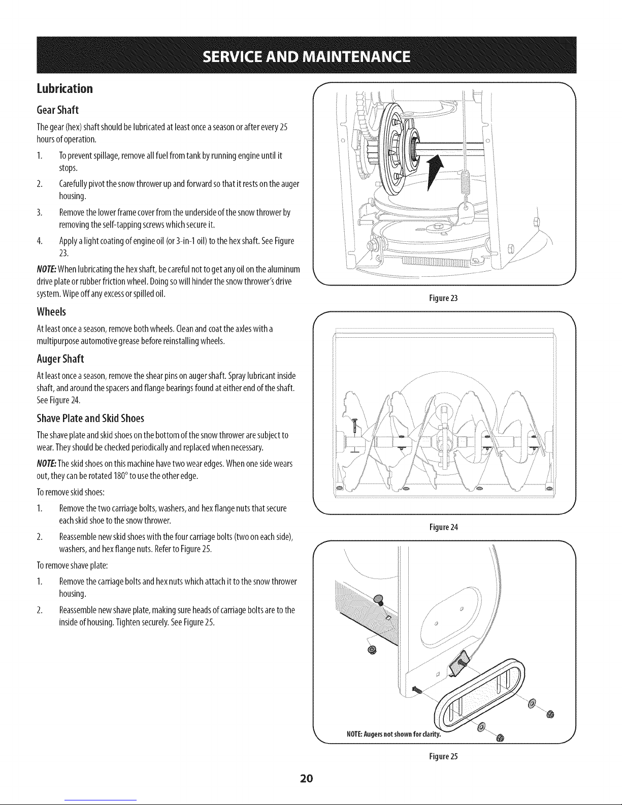
GearShaft
Thegear(hex)shaftshouldbelubricatedatleastonceaseasonorafterevery25
hoursofoperation.
I. Topreventspillage,removeallfuelfromtankbyrunningengineuntilit
stops.
2. Carefullypivotthesnowthrowerupandforwardsothatit restsontheauger
housing.
3. Removethelowerframecoverfromtheundersideof thesnowthrowerby
removingtheself-tappingscrewswhichsecureit.
4. Applya lightcoatingofengineoil(or3-in-1oil)tothehexshaft.SeeFigure
23.
NOTE:Whenlubricatingthe hexshaft,becarefulnottogetanyoilonthealuminum
driveplateorrubberfrictionwheel.Doingsowill hinderthesnowthrower'sdrive
system.Wipeoffanyexcessorspilledoil.
Wheels
Atleastonceaseason,removebothwheels.Cleanandcoattheaxleswitha
multipurposeautomotivegreasebeforereinstallingwheels.
AugerShaft
Atleastonceaseason,removetheshearpinsonaugershaft.Spraylubricantinside
shaft,andaroundthespacersandflangebearingsfoundat eitherendoftheshaft.
SeeFigure24.
ShavePlateand SkidShoes
Theshaveplateandskidshoesonthebottomofthesnowthroweraresubjectto
wear.Theyshouldbecheckedperiodicallyandreplacedwhennecessary.
flOTE:Theskidshoesonthismachinehavetwowearedges.Whenonesidewears
out,theycanberotated180°tousetheotheredge.
Toremoveskidshoes:
Removethetwocarriagebolts,washers,andhexflangenutsthatsecure
eachskidshoetothesnowthrower.
2. Reassemblenewskidshoeswiththefourcarriagebolts(twooneachside),
washers,andhexflangenuts.Referto Figure25.
Toremoveshaveplate:
1. Removethecarriageboltsandhexnutswhichattachittothesnowthrower
housing.
2. Reassemblenewshaveplate,makingsureheadsof carriageboltsareto the
insideof housing.Tightensecurely.SeeFigure25.
f
J
Figure23
f
Figure24
NOTE:Augersnot shownfor clarity.
Figure25
20
Page 21
Adjustments
Shift Cable
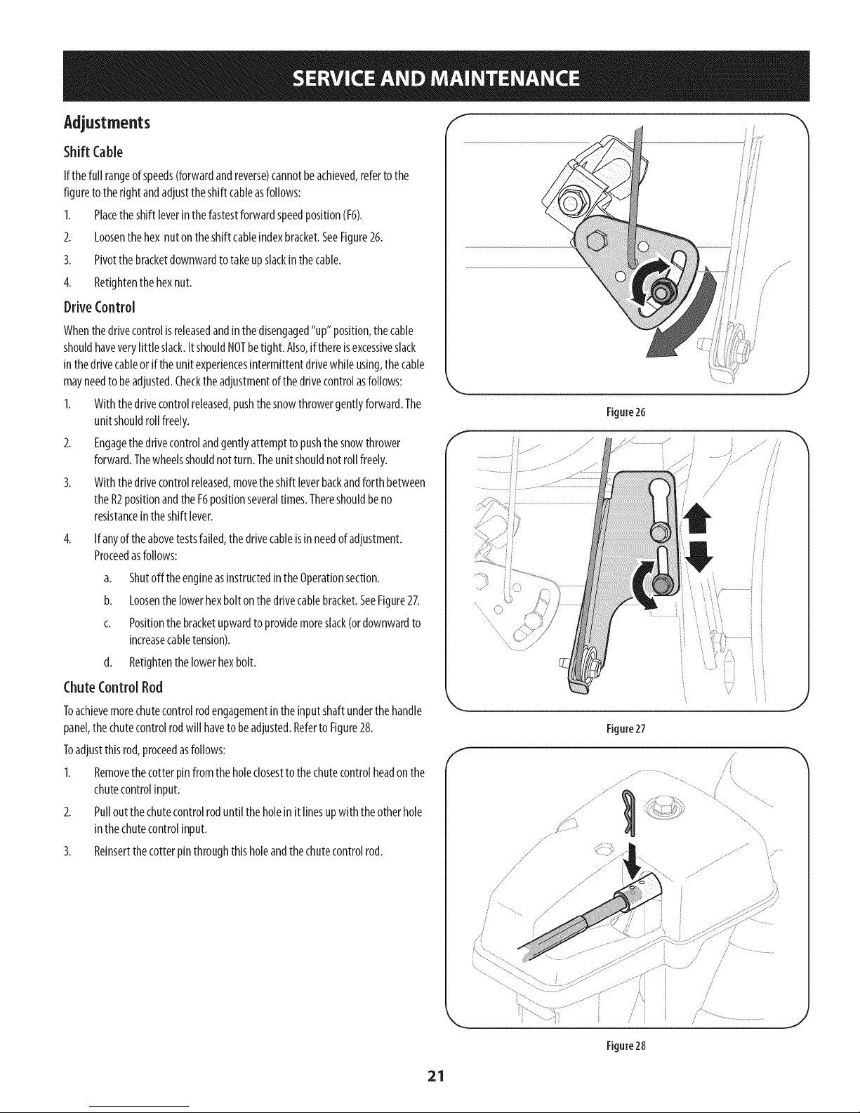
Ifthefull rangeofspeeds(forwardandreverse)cannotbeachieved,refertothe
figuretothefight andadjusttheshiftcableasfollows:
I. Placetheshiftleverinthefastestforwardspeedposition(F6).
2. Loosenthehex nutontheshiftcableindexbracket.SeeFigure26.
3. Pivotthebracketdownwardtotakeupslackinthecable.
4. Retightenthehexnut.
DriveControl
Whenthedrivecontrolisreleasedandinthedisengaged"up"position,thecable
shouldhaveverylittle slack.ItshouldNOTbetight. Also,ifthereisexcessiveslack
inthedrivecableor iftheunitexperiencesintermittentdrivewhileusing,thecable
mayneedtobeadjusted.Checktheadjustmentofthedrivecontrolasfollows:
I. Withthedrivecontrolreleased,pushthesnowthrowergentlyforward.The
unitshouldrollfreely.
2. Engagethedrivecontrolandgentlyattemptto pushthesnowthrower
forward.Thewheelsshouldnotturn.Theunitshouldnotrollfreely.
3. Withthedrivecontrolreleased,movetheshiftleverbackandforthbetween
theR2positionandtheF6positionseveraltimes.Thereshouldbeno
resistanceintheshiftlever.
f
Figure26
4. Ifanyoftheabovetestsfailed,thedrivecableisinneedofadjustment.
Proceedasfollows:
a. Shutoff theengineasinstructedintheOperationsection.
b. Loosenthelowerhexboltonthedrivecablebracket.SeeFigure27.
c. Positionthebracketupwardtoprovidemoreslack(ordownwardto
increasecabletension).
d. Retightenthelowerhexbolt.
ChuteControlRod
Toachievemorechutecontrolrodengagementintheinputshaftunderthe handle
panel,thechutecontrolrodwill havetobeadjusted.Referto Figure28.
Toadjustthisrod,proceedasfollows:
I. Removethecotterpinfromtheholeclosesttothechutecontrolheadonthe
chutecontrolinput.
2. Pulloutthechutecontrolroduntilthe holeinit linesupwith theotherhole
inthechutecontrolinput.
3. Relnsertthecotterpinthroughthisholeandthechutecontrolrod.
Figure27
i /
/
/
/
/
/
/
/
figure28
21
Page 22
AugerControl
RefertotheAssemblysectionforinstructionsonadjustingtheaugercontrolcable.
SkidShoes
RefertotheAssemblysectionforinstructionsonadjustingtheskidshoes.
8eR Replacement
Auger Belt
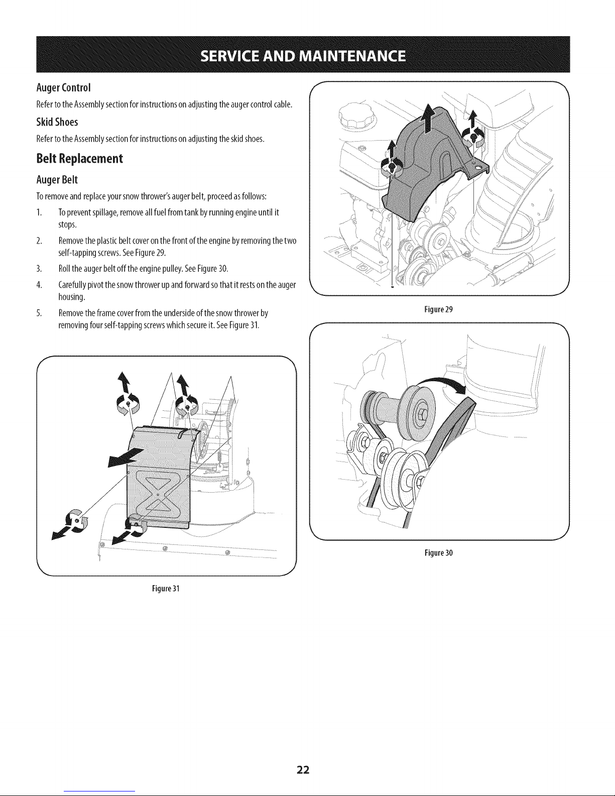
Toremoveandreplaceyoursnowthrower'saugerbelt,proceedasfollows:
1. Topreventspillage,removeallfuelfromtankbyrunningengineuntil it
stops.
2. Removetheplasticbeltcoveronthefrontoftheenginebyremovingthetwo
self-tappingscrews.SeeFigure29.
3. Rolltheaugerbeltoffthe enginepulley.SeeFigure30.
4. Carefullypivotthesnowthrowerupandforwardsothatit restsontheauger
housing.
5. Removetheframecoverfromtheundersideof thesnowthrowerby
removingfourself-tappingscrewswhichsecureit. SeeFigure31.
f
J
Figure29
f
i .................
Figure31
Figure30
J
22
Page 23
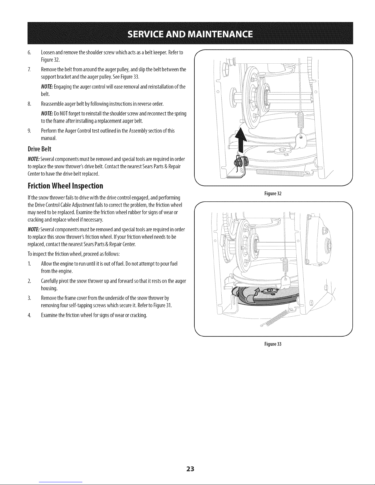
Loosenandremovetheshoulderscrewwhichactsasabeltkeeper.Referto
Figure32.
Removethebeltfromaroundtheaugerpulley,andslipthebeltbetweenthe
supportbracketandtheaugerpulley.SeeFigure33.
NOTE:Engagingtheaugercontrolwill easeremovalandreinstallationof the
belt.
8.
Reassembleaugerbeltbyfollowinginstructionsinreverseorder.
flOTE:DoNOTforgettoreinstalltheshoulderscrewandreconnectthespring
totheframeafterinstallingareplacementaugerbelt.
PerformtheAugerControltestoutlinedintheAssemblysectionofthis
manual.
Drive Belt
flOTE:Severalcomponentsmustberemovedandspecialtoolsarerequiredinorder
toreplacethesnowthrower'sdrivebelt.ContactthenearestSearsParts& Repair
Centerto havethedrivebeltreplaced.
FrictionWheelinspection
Ifthesnowthrowerfailstodrivewiththedrivecontrolengaged,andperforming
theDriveControlCableAdjustmentfailstocorrectthe problem,thefrictionwheel
mayneedtobereplaced.Examinethefrictionwheelrubberforsignsofwearor
crackingandreplacewheelifnecessary.
flOTE:Severalcomponentsmustberemovedandspecialtoolsarerequiredinorder
toreplacethissnowthrower'sfrictionwheel.Ifyourfrictionwheelneedsto be
replaced,contactthe nearestSearsParts& RepairCenter.
Toinspectthefrictionwheel,proceedasfollows:
1. Allowtheenginetorununtilit isoutoffuel.Donotattemptto pourfuel
fromtheengine.
2. Carefullypivotthesnowthrowerupandforwardsothatit restsontheauger
housing.
3. Removetheframecoverfromtheundersideof thesnowthrowerby
removingfourself-tappingscrewswhichsecureit. Referto Figure31.
4. Examinethefrictionwheelforsignsofwearorcracking.
Figure32
i •
:_ /
Figure33
23
Page 24

Ifthesnowthrowerwill notbeusedfor 30daysorlonger,orifit istheendofthesnowseasonwhenthelastpossibilityofsnowisgone,theequipmentneedsto bestored
properly.Followstorageinstructionsbelowtoensuretopperformancefromthesnowthrowerformanymoreyears.
PreparingEngine
Enginesstoredover30daysneedtobedrainedoffueltopreventdeteriorationand
gumfromforminginfuelsystemoronessentialcarburetorparts.Ifthegasolinein
yourenginedeterioratesduringstorage,youmayneedtohavethecarburetor,and
otherfuelsystemcomponents,servicedorreplaced.
1. Removeallfuelfromtankbyrunningengineuntilit stops.Donotattemptto
pourfuelfromtheengine.
2. Changetheengineoil.
3. Removesparkplugandpourapproximately1oz.(30ml)ofcleanengineoil
intothecylinder.Pulltherecoilstarterseveraltimestodistributetheoil, and
reinstallthesparkplug.
4. Cleandebrisfromaroundengine,andunder,around,andbehindmuffler.
Applyalightfilm ofoilonanyareasthat aresusceptibleto rust.
Storeinaclean,dryandwellventilatedareaawayfromanyappliancethat
operateswith aflameorpilot light,suchasafurnace,waterheater,or
clothesdryer.Avoidanyareawitha sparkproducingelectricmotor,orwhere
powertoolsareoperated.
Neverstoresnowthrowerwith fuel intank indoorsor in poorlyventilated
areas,wherefuelfumesmayreachanopenflame,sparkor pilotlight ason
afurnace,water heater,clothesdryeror gasappliance.
PreparingSnowThrower
Whenstoringthe snowthrowerin anunventilatedormetalstorageshed,
careshouldbetakento rustprooftheequipment.Usinga lightoil orsilicone,
coattheequipment,especiallyanychains,springs,bearingsandcables.
Removealldirt fromexteriorofengineandequipment.
Followlubricationrecommendations.
Storeequipmentinaclean,dryarea.
InflatethetirestothemaximumPSI.Refertotire sidewall.
Ifpossible,avoidstorageareaswith highhumidity.
Keeptheenginelevelinstorage.Tiltingcancausefueloroil leakage.
24
Page 25

25
Page 26

Disconnectthe sparkplugwireandgrounditagainsttheengineto prevent
unintendedstarting. Beforeperforminganytypeof maintenance/service,
disengageallcontrolsandstoptheengine.Waituntil aHmovingparts
havecometoa completestop.Alwayswear safetyglassesduringoperation
or while performinganyadjustmentsorrepairs.
Thissectionaddressesminorserviceissues.Tolocatethe nearestSearsServiceCenterorto scheduleservice,simplycontactSearsat1-800-4-MY=HOMP.
Engine fails to start 1.
Engine running erratically/
inconsistent RPM (hunting
or surging)
Excessive vibration
Lossof power
Unit fails to propel itself
Choke control not in CHOKE position.
2.
Spark plug wire disconnected.
3.
Faulty spark plug.
4.
Fuel tank empty or stale fuel.
5.
Engine not primed.
6.
Key not inserted.
7.
Extension cord not connected (when
using electric start button, on models so
equipped).
1. Engine running on CHOKE.
2. Stale fuel.
3. Water or dirt in fuel system.
4. Carburetor out of adjustment.
5. Over-governed engine.
1. Loose parts or damaged auger.
1. Spark plug wire loose.
2. Gas cap vent hole plugged.
1. Drive cable in need of adjustment.
2. Drive belt loose or damaged.
3. Worn friction wheel.
1. Move choke control to CHOKE position.
2. Connectwire to spark plug.
3. Clean, adjust gap, or replace.
4. Fill tank with clean, fresh gasoline.
5. Prime engine as instructed in the Operation Section.
6. Insert key fully into the switch.
7. Connect one end of the extension cord to the
electric starter outlet and the other end to a three-
prong 120-volt, grounded, ACoutlet.
1. Move choke control to RUN position.
2. Fill tank with clean, fresh gasoline.
3. Drain fuel tank by running engine until it stops. Refill
with fresh fuel.
4.
Contact your Sears Parts & Repair Center.
5.
Contact your Sears Parts & Repair Center.
1.
Stop engine immediately and disconnect spark
plug wire. Tighten all bolts and nuts. If vibration
continues, have unit serviced by a Sears Parts &
Repair Center.
1.
Connect and tighten spark plug wire.
2.
Remove ice and snow from gas cap. Be certain vent
hole is clear.
1.
Adjust drive control cable. Refer to Service and
Maintenance section.
2.
Have drive belt replaced. Contact your Sears Parts &
Repair Center.
3.
Have friction wheel replaced at a Sears Parts &
Repair Center.
NEED MORE HELP?
Find this and a[[ your other product manuals online,
Get answers from our team of home experts.
Get a personalized maintenance plan for your home.
Find information and tools to help Mth home projects.
26
Page 27

Unit fails to discharge snow
1. Chute assembly clogged. 1. Stop engine immediately and disconnect spark
plug wire. Clean chute assembly and inside of auger
housing with clean-out tool or a stick.
2. Foreign object lodged in auger.
2. Stop engine immediately and disconnect spark plug
wire. Remove object from auger with clean-out tool
or a stick.
3. Auger cable in need of adjustment.
3. Adjust auger control cable. Refer to Assembly
section.
4. Auger belt loose or damaged.
4. Replace auger belt. Refer to Service and
Maintenance section.
5. Shearpin(s) sheared.
5. Replace with new shear pin(s).
Chute fails to easily rotate
180 degrees
1. Chute assembled incorrectly.
1. Disassemble chute control and reassemble as
directed in the Assembly section.
NEED MORE HELP?
YotJU,fir_}the _: swe a_] :m,_"Yeo_:__._a_,a_emy[f_eo_@_,,,,,,,fo_' free!
o Find this and a[[ your other product manuals online.
Get answers from our team of home experts,
o Get a personalized maintenance plan for your home_
Find information and tools to help with home projects.
27
Page 28

CraftsmanSnowThrower Model247.883951
18
13
28
--48
54
7
31
39
31
i27 39/ _(
28
Page 29

CraftsmanSnowThrower Model 247.883951
m
1.
10.
11.
12.
13.
14.
15.
16.
17.
18.
19.
20.
21.
22.
23.
24.
25.
26.
27.
28.
2.
3.
4.
5.
6.
7.
8.
9.
731-2635
684-04057A-0637
710-0347
710-0451
710-04484
710-0703
712-04063
712-04064
712-04065
714-04040
936-0159
926-04012
731-07525
732-04460
736-0174
736-0242
946-04230A
931-2643
738-0143
938-0281
738-04124A
941-0245
941-0309
756-04224
790-00075
790-00080A-0637
918-04173A
684-04268-0691
Snow Removal Tool Mount
Impeller Assembly, 12" Dia.
Hex Screw, 3/8-16, 1.75, Gr5
Bolt, Carriage, 5/16-18, .750 Grl
Screw, 5/16-18, 0.750
Screw, Carriage, 1/4-20, .750, Gr5
Nut, Flange Lock, 5/16-18, Nylon
Nut, Flange Lock, 1/4-20, Nylon
Nut, Flange Lock, 3/8-16, Nylon
Cotter Pin, Bow-tie
Washer, Flat, .349 x .879 x .063
Nut, Push-on, .25 Dia
Chute, Adapter 5" Dia
Spring, Extension, .38 OD x 4.59
Washer, Wave, .625 x .885 x .015
Washer, Bell, .340 x .872 x .060
Clutch Cable, Auger, 47.23"
Snow Removal Tool
Screw, Shoulder, .498 x .34, 3/8-16
Screw, Shoulder, .625 x .17, 3/8-16
Shear Pin, .25 x 1.50
Bearing, Hex Flange x .75 ID
Bearing, Ball, .75 ID x 1.85 OD
Flat Pulley, Idler, 2.75 OD
Housing, Bearing, 1.85 ID
Bracket, Auger Idler w/Brake
Gearbox Assembly, Auger, 28"
Housing Assembly, Auger 28"
M
29.
30.
31.
32.
33.
34.
35.
36.
37.
38.
39.
40.
41.
42.
43.
44.
45.
46.
47.
48.
49.
50.
51.
52.
53.
54.
55.
56.
684-04107-4044
684-04108-4044
731-04870
736-0188
741-0493A
790-00087A-0637
790-00118-0691
731-05984A
918-0123A
918-0124A
921-0338
741-0662
710-0642
711-04283
914-0161
715-04021
917-04126
917-04861
718-04071
721-0325
721-0327
936-0351
736-3084
741-0663
741-0661 B
710-0276
920-0284
790-00181-0691
Spiral Assembly, LH
Spiral Assembly, RH
Spacer, 1.25 OD x .75 ID x 1.00
Washer, Flat, .76 x 1.49 x .06
Bushing, Flange, .80 ID x .91 OD
Housing, 1" Hex Bearing
Shave Plate, 2.25 x 27.66
Slide Shoe
Housing, Auger, RH Reduced
Housing, Auger, LH Reduced
Seal, Oil, .750 x 1.00 x .125
Bearing, Flange, .75 x 1.0 x .59
Screw, Self-tapping, 1/4-20, 0.750
Axle, Auger, 28"
Key, Hi-pro 3/16 x 5/8
Pin, Dowel, .25 OD x 1.2
Shaft, Worm .75 OD
Gear, Worm 20T
Collar, Thrust
Plug, 1/4 x .437
Seal, Oil, .75 x 1 x .131
Washer, Flat, .760 ID x 1.50D
Washer, Flat, .51 x 1.12
Bearing, Flange, .75 x 1.0 x .925
Bearing, Flange, .75 x 1.00 x .975
Screw, Carriage, 5/16-18 x 1.00
Wing Knob
Drift Cutter
29
Page 30

CraftsmanSnowThrower Model247.883951
27
/
27
! s!
/
/
/
/
3O
Page 31

CraftsmanSnowThrower Model247.883951
M
1.
2.
3.
4.
5.
6.
i
8.
9.
10.
11.
12.
13.
14.
15.
16.
17.
18.
19.
20.
21.
22.
23.
24.
25.
26.
27.
28.
29.
30.
31.
32.
33.
34.
35.
36.
37.
Available for warranty coverage only. Contact a Sears authorized
service provider for details.
984-04338A
710-04187
715-0150
747-05116
710-04370
738-04367
918-04801A
736-04446
920-0284
936-0159
731-04427A
914-0101
711-04469A
712-3087
684-04310A-0637
714-04040
712-04064
712-04063
784-5594-0637
731-06451
710-0262
710-0895
710-04071
731-06440A
710-0627
946-04528A
946-04477
753-06151
731-04893A
710-04879
710-04353
731-07031
984-04324A
753-06152
753-06153
710-1256
684-04350
715-04095
753-08018±
4-Way Chute Control TM Assembly
Hi-Lo Screw, 1/4-15 x 0.5
Roll Pin
Chute Rod
Hex Screw, 1/4-20 x 3.00
Flange Shoulder Screw
4-Way Chute Gearbox Assembly
Flat Washer, .25 x .630 x .0515
Wing Knob
Flat Washer, .349 x .879 x .063
Upper Chute
Cotter Pin
Clevis Pin
Wing Nut, 1/4-20
Chute Support Bracket
Bow Tie Cotter Pin
Flange Lock Nut, 1/4-20
Flange Lock Nut, 5/16-18
Cable Bracket
Chute Tilt Cable Guide
Carriage Bolt, 5/16-18 x 1.50
Hi-Lo Screw, 1/4-15 x .75
Carriage Bolt, 5/16-18 x 1.0
Lower Chute
Hex Screw, 5/16-24 x .750
4-Way Cable
4-Way Cable w/Clip (Not Shown)
Handle Assembly
Handle Plunger
Screw, Mach., #8-32 x .750
Screw, #8 x 1.00
Handle Lever
Shift Assembly
Gear Set Assembly
Handle Housing Assembly
Screw, #8-18 x 1.250
Joint Block Assembly
Pin
Chute Kit (Incl. Ref.# 11 & 24)
31
Page 32

CraftsmanSnowThrower Model247.883951
12
2
3
31
/
45
61.-'_
32
Page 33

CraftsmanSnowThrowerModel 247.883951
m
m
I.
2.
3.
4.
5.
6.
7.
8.
9.
1o.
11.
12.
13.
14.
15.
16.
17.
18.
19.
20.
21.
22.
23.
24.
25.
26.
27.
28.
29.
30.
31.
32.
33.
34.
35.
36.
684-o4112c
732-04238
731-04894D
684-04250
935-0199A
710-3069
731-04896B
712-04081A
684- 04111 B
631-04133A
720-0274
710-1233
738-04348
710-04586
749-04190A-0637
710-0572
720-04039
753-06437
731-05324
731-06113
631-04134B
926-0154
712-04064
732-0193
790-00311B-0637
790-00248C-0637
738-04125
920-0284
946-04396A
936-0267
914-0145
749-04138B-0637
710-04484
710-04022
936-0264
732-04677
Handle Engagement Ass'y RH
Torsion Spring
Lock Plate
Pivot Rod
Rubber Bumper
Screw, 1/4-20 x .500
Clutch Lock Cam
Shoulder Nut, 1/4-20
Handle Engagement Assembly LH
Handle Clutch Lock LH Assembly
Handle Grip
Screw, #10-24 x 0.375
Shoulder Screw, 1/4-20
Screw, 1/4-20 x 1.625
Upper Handle RH
Carriage Screw, 5/16-18 x 2.25
Shift Knob
Handle Panel
Lens
Steering Control
Handle Clutch Lock RH Assembly
Cable Tie
Flange Lock Nut, 1/4-20
Compression Spring
Shift Lever
Panel Bracket
Shoulder Screw
Wing Knob
Speed Selector Cable
Flat Washer
Click Pin
Lower Handle
Screw, 5/16-18 x 0.75
Screw, M8-1.25
Flat Washer, .330 x .630 x .0635
Cable Control Wire
37.
38.
39.
40.
41.
42.
43.
44.
45.
46.
47.
48.
49.
50.
51.
52.
53.
54.
55.
56.
57.
58.
59.
60.
61.
62.
63.
64.
65.
66.
67.
68.
69.
N/A
749-04191A-0637
710-04326
732-04219C
738-04126
716-04036
925-06095
710-I 652
731-06401
926-04012
756- 04109
736-0505
738-04439
936-0119
684-04169
790-00332-0637
750-04571
732-04308A
710-0672
756-04252
954-04201A
710-0809
790-00208D
748-04112B
750-04477A
710-0654A
750-04303
756- 04113
736-3082A
710-0191
748-04053A
710-1245B
954- 04195A
936-0329
725-05147
Upper Handle LH
Screw, #8-16 x 0.50
Clutch Lock Spring
Pin, 3/16
Retainer Ring
Headlight Socket
AB Screw, 1/4-20 x 0.625
Belt Cover
Push-on Nut
Auger Pulley
Flat Washer
Shoulder Screw
Lock Washer
Idler Pulley Assembly
Pit., Cvr.
Spacer
Torsion Spring
Hex Screw, 5/16-24 x 1.25
Pulley Half
Belt, Wheel Drive
TT Screw, 1/4-20 x 1.25
Drive Clutch Idler Bracket
Shoulder Spacer
Spacer
TT Seres Screw, 3/8-16 x 1.0
Spacer
Pulley Half
Flat Washer
Hex Bolt, 3/8-24 x 1.25
Pulley Adapter
Hex Bolt, 5/16-24 x 0.875
V-Belt,.500 x 35.00 Lg
Lock Washer
Engine (see breakdown)
MTD Model No. 952Z270-SUA
Light Harness (Not Shown)
33
Page 34

CraftsmanSnowThrowerModel247.883951
42
2
I
36
20
10
22
14 l
13
20
I
26 45 24
I
28
57
62
58
34
Page 35

CraftsmanSnowThrower Model247.883951
m
m
1.
2.
3.
4.
5.
6.
7.
8.
9.
10.
11.
12.
13.
14.
15.
16.
17.
18.
19.
20.
21.
22.
23.
24.
25.
26.
27.
28.
29.
30.
31.
735-04099
711-1268B
946-05067
732-04345
790-00207C
684-04156A
750-04474
914-0126
735-04100
917-04210
941-0245
790-00206A-0637
756-0625
738-0924A
618-06988
618-06987
936-3015
732-04311A
731-05297
916-0104
736-0188
750-06087
941-0563
938-04180
731-04873
710-0788
790-00527-0691
634-04145-0911
634-04146-0911
710-05339
684-04154B-0637
790-00096A-0637
748-0190
Plug, 3/8 ID
Actuator Shaft
Drive Clutch Cable
Extension Spring
Drive Clutch Cable Guide Bracket
Shift Rod Assembly
Axle Support Tube
Hi Pro Key
Plug, 1/2 ID
Gear, 56T
Hex Flange Bearing
Auger Clutch Cable Guide Bracket
Cable Roller
C Screw, 1/4-28 x 0.375
Dogg Assembly - LH
Dogg Assembly - RH
Washer, Flat
Torsion Spring, .750 ID x .968 Lg.
Spacer
E Ring
Flat Washer, .76 x 1.49 x .06
Spacer
Ball Bearing
Axle
Spacer
TT Screw, 1/4-20 x 1.0
Shaft Retainer- LH
Wheel Complete - LH
Wheel Complete - RH
Screw, 5/16-24 x 0.75
Friction Wheel Support Brkt. Assy.
Auger Cable Guide Bracket
Spacer
32.
33.
34.
35.
36.
37.
38.
39.
40.
41.
42.
43.
44.
45.
46.
47.
48.
49.
50.
51.
52.
53.
54.
55.
56.
57.
58.
59.
60.
61.
62.
63.
738-04184A
790-00316-0691
656-04055
918-06072
684-04153C
716-0136
726-0221
790-00183C-0691
932-0264
712-0417A
946-0956C
790-00528-0691
750-0767
712-04065
710-0751
790-00217A-0637
790-00218A-0637
712-04063
712-04064
618-0063A
935-04054
790-00174C
710-04484
710-1652
918-06054
918-06056
711-06117
916-0231
717-05146
717-1209A
736-04581
736-05031
Shoulder Screw
Frame Cover
Friction Wheel Disc Assembly
Drive Shaft Assembly
Friction Wheel Assembly
Retainer Ring
Speed Nut
Wheel Drive Frame
Extension Spring
Flange Nut, 5/8-18
Steering Cable
Shaft Retainer- RH
Axle Spacer
Flange Lock Nut, 3/8-16
Hex Screw, 1/4-20 x .620
Speed Selector Pivot Bracket
Speed Selector Shift Bracket
Flange Lock Nut, 5/16-18
Flange Lock Nut, 1/4-20
Friction Wheel Bearing Assembly
Friction Wheel
Friction Plate
Screw, 5/16-18 x .750
AB Screw, 1/4-20 x 0.625
Gear Assembly, Plantry Ring
Carrier Assembly, Plantry Ring
Shaft, Strbl Drv Hex, .812
E-Ring
Gear, Sun, 18T
Gear, 12T
Washer, Thrust, .75 x 1.25 x .03
Washer, Flat, .67 x 1.174 x .02
35
Page 36

CraftsmanEngineModel478-SUBForSnowModel247.883951
D _ o 0
1
710-04915
2
951-11194
3
710-04915
4
951-10757
5
951-11594
7
731-05632
8
951-10637
9
951-11302
10
710-04914
11
951-11181
12
951-11227
13
710-04968
14
951-11195
15
712-05015
Bolt, M6x12
Muffler Shield
Bolt M6x12
Throttle Control Knob
Control Panel
Key
Key Switch Assembly
Choke Knob
Bolt M6xlO
Exhaust Pipe Shield
Carb Isolator Bracket
Bolt M6x16
Muffler Assembly
Nut, M8
36
Page 37

CraftsmanEngineModel 478-SUBForSnowModel247.883951
133--
129
130
131
132
133
134
135
137
138
139
140
145
a
b
C
d
e
f
g
h
710-04963
951-11225
951-11222
951-11223
951-14024A
951-10639A
951-11824
951-11190
951-11192
736-04477
712-05015
951-12762A
n/a
736-04638
710-05469
n/a
n/a
n/a
n/a
n/a
9
h
i
O
P
m
o1139
13o7o 140--_
145- Carburetor Kit
D - o 0
Stud M6-8x10⁴
Carburetor Insulator Gasket
Carburetor Insulator
Carburetor Gasket
Carburetor Assembly
Primer Assembly
Primer
Heater Box
Choke Control
LockWasher
NutM6
Carburetor Kit (Incl. ij,p,q,r,s,t,u,v,x,z)
Choke Shaft
LockWasher
Screw M3x6
Choke Plate
Throttle Shaft
Throttle Plate
Gasket
Throttle Shaft Cover
140_
D - o o
n_
I
n_
J
k
n_
I
n_
751-11991
m
n
951-11906
O
n/a
n/a
P
n/a
q
r
n/a
s
n/a
t
n/a
n/a
U
V
951-11970
W
n/a
951-11348
X
710-04945
Y
Z
951-11349
aa
710-04938
Idle Jet Rivet
Idle Jet Assembly
Idle Speed Adjusting Screw
Primer Pipe
Primer Hose
Hose Clamp
Carburetor Body
Float Pin
Emulsion Tube
Needle Valve
Main Jet
Needle Valve Spring
Float
Fuel Bowl Gasket
Fuel Bowl
Fuel Bowl Gasket
Fuel Bowl Mounting Bolt
Fuel Drain Plug Gasket
Fuel Drain Plug
37
Page 38

CraftsmanEngineModel478-SUBForSnowModel247.883951
68
142- Gasket Kit- Complete
61
144- Complete Engine
418
42
38
Page 39

CraftsmanEngineModel 478-SUBForSnowModel247.883951
4O
41
42
43
44
48
49
5O
51
52
53
54
55
56
57
58
59
6O
61
62
64
64
65
951-12066
951-12043
951-I 1632
951-12044
951-12387
751-12068
951-12069
736-04453
714-04077
951-I 1958
951-12071
951-11229
951-10307
715-04102
715-04092
951-12072
951-I 1374
736-04545
951-11283
951-11577
951-12395
951-11228
951-11372
ID _ o o
Connecting Rod Assembly
Piston
Piston Pin Snap Ring
Piston Pin
Piston Ring Set
Governor Gear/Shaft Assembly
Radial Ball Bearing
Washer 8x20xO.8
Cotter Pin
Governor Seal
Governor Arm Shaft
Crankshaft Kit (Incl. 49,54,55,65,81)
Woodruff Key
Dowel Pin 9x12
Dowel Pin 7x14
Camshaft Assembly
Crankcase Cover Gasket
Washer 16x24xO.5
Oil Fill Plug Assembly
O-Ring
Crankcase Cover
Crankcase Cover Kit
(Incl. 49,59,50,64-68)
Oil Seal, 30x46x8
m
66
67
68
69
70
71
73
74
75
76
77
78
79
80
81
142
143
144
710-04971
710-04972
710-05052
710-04968
951-11320
710-05349
951-11904
951-12073
951-11381
951-11971A
951-11230
951-11187
951-11350
736-04440
710-04906
751-11498
951-11209
951-11210
952Z478-SUB
ID _ o o
Bolt M8x38
Bolt M8x45
Bolt M8x35
Bolt M6x16
Dipstick Clamp
Bolt M6x8
Oil Fill Tube O-Ring
Oil Fill Tube Assembly
Dipstick O-Ring
Dipstick Assembly
Crankcase Kit (Incl. 49,52,77,81)
Short Block Assembly
(Incl. 40-44,48-68,77-81,103,
106,107,109,111,124,130-132)
Oil Drain Pipe
Washer lOx16x1.5
Oil Drain Plug
Oil Seal 30x46x8
Gasket Kit - Complete (Incl. 52,59,65,79,
81,107,109,124,130-132)
Gasket Kit - External
(Incl. 79,109,124,130-132)
Complete Engine
39
Page 40

CraftsmanEngineModel478-SUBForSnowModel247.883951
123
123
142-GasketKit-Complete
143- 6asker Kit- External
144- Complete Engine
4O
Page 41

CraftsmanEngineMode[478-SUBForSnowMode[247.883951
n
101
103
104
105
106
107
108
109
110
110
111
112
113
114
115
116
117
118
119
120
121
122
123
124
125
126a
126b
127
128
141
142
143
144
951-11198
951-11962
951-11199
951-11226
951-11188
715-04097
951-12076
951-10292
951-11212
710-04964
951-11207
710-04965
951-11964
951-12077
951-12078
951-12080
951-12081
951-11965
951-11981
710-04962
951-11966
751-11123
751-11124
710-05054
951-11967
951-11220
731-07059
726-04101
951-11180
710-04915
951-11333
951-11209
951-11210
952Z478-SUB
Valve Kit
Tappet
Push Rod Kit
Cylinder Head Kit (Inc1.107,111,112,125)
Cylinder Head Assembly (Inc1.101,102,
105,107, 109-122,124,129-132)
Dowel Pin 12x20
Gasket, Cylinder Head
Spark Plug/F6Rtc
Exhaust Pipe Gasket
Stud M8x48.5
Muffler Stud Assembly
Bolt M10x1.25x80
Valve Seal (Intake)
Valve Spring Retainer(Intake)
Valve Spring
Valve Spring Retainer
Exhaust Lash Cap
Push Rod Guide
Rocker Arm Assembly
Bolt, Pivot
Rocker Arm
Adjusting Nut ,Valve
Nut, Pivot Locking
Valve Cover Bolt
Valve Cover Gasket
Valve Cover
Breather Hose
Breather Hose Clamp
Air Shield
Bolt M6x12
Valve Cover Kit
Gasket Kit- Complete (Incl. 52,59,65,
79,81,107, 109,124,130-132)
Gasket Kit- External
(Incl. 79,109,124,130-132)
Complete Engine
D _ o o
41
Page 42

CraftsmanEngineModel478-SUBForSnowModel247.883951
46
91
94 96
94
9O
P
_'-99
D - o o
45
710-04965
46
951-11196
47
710-04967
82
951-11498
83
951-11197
85
951-12553
86
710-04969
87
710-04966
88
951-II186
89
951-12090
Bolt M4x55
Electric Starter
Bolt M8x55
Ignition Coil Assembly
Ignition Coil Bolt
Alternator Assembly
Bolt M6x30
Bolt M6x8
Wire Plate
Flywheel
90
951-11217
91
951-11218
92
712-04220
93
710-04968
94
710-04915
96
951-11379
97
951-11208
98
736-04455
99
710-04974
Cooling Fan
Starter Cup
Nut, Special, M16x1.5
Bolt M6x16
Bolt M6x12
Blower Housing
Recoil Starter
Gasket 6
Bolt M6xlO
D- oo
42
Page 43

CraftsmanEngineModel 478-SUBForSnowModel247.883951
25
3A 32
D _ o o
16
951-12533
17
951-11933
18
710-04970
19
750-05312
20
750-05313
21
951-11201
22
951-11184
23
951-11183
24
951-12385
25
710-04968
26
736-04452
27
951-11200
Fuel Cap Assembly
Fuel Level Indicator
Bolt M8x20
Bushing
Bushing
Fuel Tank Assembly
Governor Cover
Rear Mainting Bracket Assy.
Decorate Cover
Bolt M6x16
Bush
Fuel Line Kit
28
951-11700
29
710-04921
30
951-11182
32
712-04212
33
710-04908
34
951-11231
35
951-11202
36
951-11203
37
951-11204
38
951-11213
39
710-04915
Fuel Hose Clamp
Bolt M8x14
Gas Tank Support Bracket
Nut M6
Governor Arm Bolt
Governor Arm
Governor Spring
Throttle Linkage Spring
Throttle Linkage
Primer Bracket
Bolt, M6x12
ID - o o
43
Page 44

CraftsmanSnowThrower ModeJ247.883951
• -- " _ 1001 LflO-NV]lO •
N3HMNOIlflVO VULX33$fl "S930NVIS19LV399VHOSIQ
10391093A]N 'S31HflrNI S103r80 NMOUHI OIOAV Ol "_
390J38 03ddOIS 3AVH 81_JVdONIAOI_IIV IIINNS310NVH
QNIH38NIVW3HONV ']NION3 dOIS '893A31 901nlo 30VON3810 "_
"31fiND ]9UVHOSIO OOlONfl Ol lOOl lflO-NV]19 3Sfl "Z
"133d ONVSONVH31VlfldWV NVO 930flV 90 9Bll3dWI HIlM
lOVlNOO "B]gflV ONVU3113dWI 9NllVlOU WOBdAVAAVd33H "L
777S32636
"IVflNVW S,UO/VU3dO QV3U "G
"S30V_UflS 13AV_O NO9NI/VU3dO
'3NIHOVVJ ONIOIAH3S HO ONIOOO1ONfl
777S32236
777122363
777122339
777D16338
STARTING INSTRUCTIONS:
777D19073
777D16340
777X43688
777122340
/ CONTAININGMORE
THAN 10%ETHANOL
777D18035
44
Page 45

FEDERALand/or CALIFORNIAEMISSIONCONTROLWARRANTYSTATEMENT
YOURWARRANTYRIGHTSANDOBLIGATIONS
MTD Consumer Group Inc, the United States Environmental Protection Agency (EPA), and for those products certified for sale in the state of
California, the California Air Resources Board (CARB) are pleased to explain the emission (evaporative and/or exhaust) control system (ECS)
warranty on your 2013 and later small off-road spark-ignited engine and equipment (outdoor equipment engine). In California, new outdoor
equipment engines must be designed, built and equipped to meet the State's stringent anti-smog standards (in other states, outdoor
equipment engines must be designed, built, and equipped to meet the U.S. EPA small off-road spark ignition engine regulations). MTD
Consumer Group Inc must warrant the ECSon your outdoor equipment engine for the period of time listed below, provided there has been no
abuse, neglect, or improper maintenance of the outdoor equipment engine.
Your ECS may include parts such as the carburetor, fuel-injection system, ignition system, catalytic converter, fuel tanks, fuel lines, fuel caps,
valves, canisters, filters, vapor hoses, clamps, connectors, and other associated emission-related components.
Where a warrantable condition exists, MTD Consumer Group Inc will repair your outdoor equipment engine at no cost to you including
diagnosis, parts, and labor.
MANUFACTURER'SWARRANTYCOVERAGE:
This emission control system is warranted for two years. If any emission-related part on your outdoor equipment engine is defective, the
part will be repaired or replaced by MTD Consumer Group Inc. In the event that a component is covered for longer than two years by the
Manufacturer's equipment warranty, the longer coverage period will apply.
/
OWNERSWARRANTYRESPONSIBILITIES:
As the outdoor equipment engine owner, you are responsible for performance of the required maintenance listed in your owner's manual. MTD
Consumer Group Inc recommends that you retain all receipts covering maintenance on your outdoor equipment engine, but MTD Consumer
Group Inc cannot deny warranty solely for the lack of receipts.
As the outdoor equipment engine owner, you should however be aware that MTD Consumer Group Inc may deny you warranty coverage if
your outdoor equipment engine or a part has failed due to abuse, neglect, improper maintenance, or unapproved modifications.
You are responsible for presenting your outdoor equipment engine to MTD Consumer Group Inc's distribution center or service center as soon
as the problem exists. The warranty repairs should be completed in a reasonable amount of time, not to exceed 30 days. If you have a question
regarding your warranty coverage, you should contact the MTD Consumer Group Inc Service Department at 1-800-800-7310 or at
http://su pport.mtd prod ucts.com.
GENERALEMISSIONSWARRANTYCOVERAGE:
MTD Consumer Group Inc warrants to the ultimate purchaser and each subsequent purchaser that the outdoor equipment engine is: (1)
designed, built, and equipped so as to conform with all applicable regulations; and (2) free from defects in materials and workmanship that
cause the failure of a warranted part for a period of two years.
The warranty period begins on the date the outdoor equipment engine is delivered to an ultimate purchaser or first placed into service.
Subject to certain conditions and exclusions as stated below, the warranty on emission-related parts is as follows:
1. Any warranted part that is not scheduled for replacement as required maintenance in the written instructions supplied is warranted for
the warranty period stated above. If the part fails during the period of warranty coverage, the part will be repaired or replaced by MTD
Consumer Group Inc according to subsection (4) below. Any such part repaired or replaced under warranty will be warranted for the
remainder of the period.
2. Any warranted part that is scheduled only for regular inspection in the written instructions supplied is warranted for the warranty period
stated above. Any such part repaired or replaced under warranty will be warranted for the remaining warranty period.
3. Any warranted part that is scheduled for replacement as required maintenance in the written instructions supplied is warranted for the
period of time before the first scheduled replacement date for that part. If the part fails before the first scheduled replacement, the part
will be repaired or replaced by MTD Consumer Group Inc according to subsection (4) below. Any such part repaired or replaced under
warranty will be warranted for the remainder of the period prior to the first scheduled replacement point for the part.
4.
Repair or replacement of any warranted part under the warranty provisions herein must be performed at a warranty station at no charge
to the owner.
5. Notwithstanding the provisions herein, warranty services or repairs will be provided at all of our distribution centers that are franchised to
service the subject engines or equipment.
6. The outdoor equipment engine owner will not be charged for diagnostic labor that is directly associated with diagnosis of a defective,
emission-related warranted part, provided that such diagnostic work is performed at a warranty station.
7. MTD Consumer Group Inc is liable for damages to other engine or equipment components proximately caused by a failure under
warranty of any warranted part.
8. Throughout the off-road engine and equipment warranty period stated above, MTD Consumer Group Inc will maintain a supply of
warranted parts sufficient to meet the expected demand for such parts.
9. Any replacement part may be used in the performance of any warranty maintenance or repairs and must be provided without charge to
the owner. Such use will not reduce the warranty obligations of MTD Consumer Group Inc.
Page 46

10. Add-onormodifiedpartsthatarenotexemptedbytheAirResourcesBoardmaynotbeused.Theuseofanynon-exemptedadd-onor
modifiedpartsbytheultimatepurchaserwillbegroundsfordisallowingawarrantyclaims.MTDConsumerGroupIncwillnotbeliableto
warrantfailuresofwarrantedpartscausedbytheuseofanon-exemptedadd-onormodifiedpart.
WARRANTEDPARTS:
The repair or replacement of any warranted part otherwise eligible for warranty coverage may be excluded from such warranty coverage if
MTD Consumer Group Inc demonstrates that the outdoor equipment engine has been abused, neglected, or improperly maintained, and that
such abuse, neglect, or improper maintenance was the direct cause of the need for repair or replacement of the part. That notwithstanding,
any adjustment of a component that has a factory installed, and properly operating, adjustment limiting device is still eligible for warranty
coverage. Further, the coverage under this warranty extends only to parts that were present on the off-road engine and equipment purchased.
The following emission warranty parts are covered (if applicable):
1. Fuel Metering System
Cold start enrichment system (soft choke)
Carburetor and internal parts (or fuel injection system)
Fuel pump
Fuel tank
2. Air Induction System
Air cleaner
Intake manifold
3. Ignition System
Spark plug(s)
Magneto ignition system
4. Exhaust System
Catalytic converter
SAI (Reed valve)
5. Miscellaneous Items Used in Above System
Vacuum, temperature, position, time sensitive valves and switches
Connectors and assemblies
6. Evaporative Control
Fuel hose
Fuel hose clamps
Tethered fuel cap
Carbon canister
Vapor lines
050790 Rev.A
Page 47

Congratulationsonmakingasmartpurchase.YournewCraftsman®productisdesignedandmanufacturedforyearsof
dependableoperation.Butlikeallproducts,it mayrequirerepairfromtimetotime.That'swhenhavinga RepairProtection
Agreementcansaveyoumoneyandaggravation.
Here'swhat the RepairProtectionAgreement_ includes:
[] Expertservicebyour10,000professionalrepairspecialists
[] Unlimitedserviceand nocharge forpartsandlaboronallcoveredrepairs
[] Productreplacementupto $1500ifyourcoveredproductcan'tbefixed
[] Discountof 25%from regularpriceofserviceandrelatedinstalledpartsnotcoveredbytheagreement;also,25%off
regularpriceofpreventivemaintenancecheck
[] Fasthelpby phone- wecallitRapidResolution- phonesupportfromaSearsrepresentative.Thinkofusasa"talking
owner'smanual."
OnceyoupurchasetheRepairProtectionAgreement,asimplephonecallisallthatit takesforyoutoscheduleservice.You
cancallanytimedayornight,orscheduleaserviceappointmentonline.
TheRepairProtectionAgreementisarisk-freepurchase.Ifyoucancelfor anyreasonduringtheproductwarrantyperiod,
wewill provideafull refund.Or,aproratedrefundanytimeaftertheproductwarrantyperiodexpires.PurchaseyourRepair
ProtectionAgreementtoday!
Somelimitations and exclusionsapply. Forpricesand additional informationinthe U.S.A.call1-800-827-6655.
_CoverageinCanadavariesonsomeitems.Forfull detailscall SearsCanadaat 1-800-361-6665.
SearsInstallationService
ForSearsprofessionalinstallationof homeappliances,garagedooropeners,waterheaters,andothermajorhomeitems,in
theU.S.A.orCanadacall1-800-4-MY-HOME®.
47
Page 48

Declarad6n de garantia ....................... P_gina 48
Pr_cticas operaci6n seguras ................... P_gina 49
Montaje ...................................... P_gina 53
Operad6n .................................... P_gina 59
Servido y Mantenimiento ..................... P_gina 63
Almacenamiento fuera de temporada ......... P_gina 70
Solucidn de problemas ........................ P_gina 71
Acuerdo de proteccidn para reparaciones ...... P_gina 75
Lista de piezas ................................ P_gina 28
Numero de servicio .................. Cubierta posterior
GARANTIACOMPLETACRAFTSMANPORDOSANOS
PORDOSA%Sapartirdelafechadelacompra,esteproductoest_garantizadopordefectosenlosmaterialesylamanodeobra.
Losproductosdefectuososser_nreparadossincostooreemplazadossincostosilareparaci6nnoest_disponible.
GARANTIADEPORVIDALIMITADAADICIONALen la tolva de UPPERy LOWER
PARASIEMPREYCUANDOSEUTILIZAporelpropietariooriginaldespu_sdelsegundoahodesdelafechadecompra,elconductosuperioreinferiordeeste
quitanievesest_ngarantizadoscontracualquierdefectodematerialesomanodeobradebeserverificadoporunproveedordeservicioautorizadoSears.Con
elcomprobantedecompra,ustedrecibir_unarampanuevadeformagratuita.Ustedesresponsableporelcostodelamanodeobradeinstalaci6nyotros
gastosocasionadosparaverificareldefect&
Paraobtenerinformaci6nsobreelalcancedelagarantiaysolicitarlareparaci6noelreemplazo,visiteelsitioWeb:www.craftsman.com
EstagarantiacubreI]NICAMENTElosdefectosenlosmaterialesyenlamanodeobra.EstagarantiaNOcubre:
Elementosnorenovablesquepuedendesgastarseporelusonormal,duranteelplazodelagarantia,incluyendoentreotros,lasbarrenas,laspaletasde
lasbarrenas,loscortadoresdedesplazamiento,laszapatasantideslizantes,laplacaderaspado,lospasadoresdecuchilla,labujia,elfiltro deaire,las
correasyelfiltro deaceite.
Serviciosdemantenimientoest_ndar,cambiosdeaceiteoafinaci6n.
Cambiodeneum_ticosoreparacionesporpinchadurasconobjetosexternoscomoclavos,espinas,toconesovidrios.
Reemplazooreparaci6ndeneum_ticosoruedascomoresultadodeldesgastenormal,unaccidente,ofuncionamiento
omantenimientoincorrectos.
• Reparacionesrequeridascomoresultadodelusoinadecuadoporpartedeloperador,incluyendoentreotroseldahoocasionadoporobjetosque
impactanlam_quinayquetuercenelbastidor,elejedelabarrena,etc.,odebidoaqueelmotorrueaceleradoenexceso.
Reparacionesnecesariasdebidoanegligenciadeloperador,incluyendoentreotros,dahosmec_nicoy el_ctricoocasionadopor
unalmacenamientonoapropiado,fallaporelusodeaceitedegradoy/ocantidadnoapropiadosofallapornodarmantenimiento
alequipodeacuerdoconlasinstruccionescontenidasenelmanualdeloperador.
Limpiezaoreparacionesdelmotor(sistemadecombustible)debidasacombustiblequesedeterminaest_contaminadouoxidado(viejo).Engeneral,el
combustibledebeutilizarseenunperiodonomayorde30diasapartirdesuadquisici6n.
Eldeterioroydesgastenormaldelosacabadosexteriores,oreemplazodelaetiquetadelproducto.
LapresentegarantiaseanulasiseutilizaesteproductoalgunavezparaprestarservicioscomercialesosiseIoalquilaaotrapersona.
Estagarantialeotorgaderechoslegalesespecificos,peroustedpodriagozardeotrosderechosenraz6ndesulugarderesidencia.
SearsBrandsManagementCorporation,HoffmanEstates,IL60179
Aceite del motor: 5W-30
Combustible: Gasolina sin plomo
Motor: MTD
Numero de modelo
Numero de serie
Fecha de compra
© Sears Brands, LLC
Registre el numero de modelo, numero de serie y fecha
48
de compra m_s arriba.
Page 49

Lapresendadeestesimboloindicaquesetrata deinstrucdones
importantesdeseguridadquesedebenrespetarparaevitar poneren
peligrosuseguridadpersonaly/o materialy Jadeotraspersonas.Leaysiga
todaslasinstrucdonesdeestemanualantesde ponerenfundonamiento
estam_iquina.SinorespetaestasinstrucdonespodriaprovocarJesiones
personales.Cuandoyeaestesimbolo,ipresteatend6n aJaadvertenda!
Estam_iquinarueconstruidaparasetoperadadeacuerdoconJasregJas
deseguridadcontenidasen estemanual.AIigualqueconcualquiertipo
deequipomotorizado,undescuidooerrorporpartedeloperadorpuede
produdr lesionesgraves.Estam_iquinaescapazdeamputarmanosy pies
y dearrojarobjetoscongranfuerza.Deno respetarlasinstruccionesde
seguridadsiguientesse puedenproducirlesionesgravesola muerte.
PROPOSICION 65 DE CALiFORNiA
EJescapedel motordeesteproducto,algunosdesuscomponentesy
algunoscomponentesdeJvehkulo contienenoJiberansustandasquimkas
queeJestadodeCaliforniaconsideraquepuedenprodudr c_incer,defectos
denadmiento uotros probJemasreproductivos.
CAPACITACIC) N
Lea,entiendaycumplatodaslasinstruccionesinduidasenlam_quinayen
losmanualesantesdemontarlayutiJizarJa.Guardeestemanualenunlugar
seguroparaconsultasfuturasyperi6dicas,asicomoparasolicitarrepuestos.
Leael Manualdel0peradorysigatodasJasadvertenciase instrucdonesde
seguridad.Elfracasodehacerasipuedecausarlaheridaseriaaloperadory/o
personaspresentes.
Familiaricesecontodosloscontrolesyconelusoadecuadodelosmismos.
Sepac6modetenerlam_quinaydesactivarloscontrolesr_pidamente.
Nopermitanuncaquelosniffosmenoresde14afrosutilicenestam_quina.
Losniffosde14afrosenadelantedebenleeryentenderlasinstrucaones
deoperaci6ny normasdeseguridadcontenidasenestemanual,yenla
m_quinaydebenserentrenadosysupervisadosporunadulto.
Nuncapermitaquelosadultosoperenestam_quinasinredbirantesla
instrucci6napropiada.
Losobjetosarrojadosporlam_quinapuedenproduarlesionesgraves.
Planifiqueelpatr6nenelquevaair arrojandonieveparaevitarquela
descargadematerialserealicehadaloscaminos,losobservadores,etc.
Mantengaa losobservadores,ayudantes,mascotasyniffosporIo menosa
75piesdelam_quinamientraslamismaest_enfundonamiento.Detengala
m_quinasialguienseacerca.
Seaprecavidoparaevitarpatinarseocaerseespedalmentecuandooperala
m_quinaenreversa.
Su responsabJlJdad--Restrinja el usodeestam_iquinamotorizada
aJaspersonasqueJean,comprendanyrespetenJasadvertendase
instrucdonesqueaparecenenestemanuaJy enJam_iquJna.
iGUARDEESTASINSTRUCCIONES!
PREPARATWOS
Inspeccioneminuciosamenteel_ireadondeutiJizar_ielequipo.Saquetodoslos
felpudos,peri6dJcos,trineos,tablas,cablesyotrosobjetosextrahosconlosque
podriatropezaro quepodrianserarrojadosporlabarrena/impulsor.
ParaprotegerselosojosutilJcesiempreanteojosoantiparrasdeseguridad
mientrasoperalam_iquJnaomientraslaajustaorepara.Losobjetos
arrojadosquerebotanpuedenproducirlesionesocularesgraves.
Nooperelam_iquinasinlavestimentaadecuadaparaestaralairelibreen
invierno.NoutilJcealhajas,bufandaslargasuotrasprendassueltasque
podrianenredarseenlaspartesm6viles.Utiliceuncalzadoespecialpara
superficiesresbaladizas.
Useunprolongadoryuntomacorrientedetrescablesconconexi6natierra
paratodaslasm_iquinasconmotoresdeencendidoel_ctrico.
AjustelaalturadeJacajadeltomacorrienteparalimpiarlagravao las
superficiesconpiedrastrituradas.
Desengranetodaslaspalancasdecontrolantesdearrancarelmotor.
Nuncaintenterealizarajustesmientraselmotorest_enmarchaexceptoen
loscasosespedficamenterecomendadosenelmanualdeloperador.
Dejequeelmotoryla m_quinaseadaptenalatemperaturaexteriorantes
decomenzarasacarlanieve.
49
Page 50

Manejo seguro de la gasolina
Paraevitarlesionespersonaleso daffosmaterialestengamuchocuidadocuando
trabajecongasolina.Lagasolinaessumamenteinflamableysusvaporespueden
causarexplosiones.Sisederramagasolinaencimaosobrelaropasepuedelesionar
gravementeyaquesepuedeincendiar.L_iveselapielyc_imbiesederopade
inmediato.
Utilices61olosredpientesparagasolinaautorizados.
Apaguetodoslosdgarrillos,dgarros,pipasyotrasfuentesdecombusti6n.
Nuncacarguecombustibleenlam_quinaenunespadocerrado.
Nuncasaquelatapadelcombustibleniagreguecombustiblemientrasel
motorest_calienteoenmarcha.
DejequeelmotorseenfrieporIo menosdosminutosantesdevolvera
cargarcombustible.
NuncaIleneenexcesoeldep6sitodecombustible.Lleneeltanqueanom_s
de1/2pulgadapordebajodelabasedelcuellodeIlenadodejandoespacio
paraladilatad6ndelcombustible.
Vuelvaacolocarlatapadelagasolinayajustelabien.
Limpieel combustiblequesehayaderramadosobreelmotoryelequipo.
Trasladelam_quinaaotrazona.Espere5minutosantesdeencenderel
motor.
Nuncaalmacenela m_iquinaoelredpientedecombustibleenunespado
cerradodondehayafuego,chispasoluzpiloto(porejemplo,hornos,
calentadoresdeagua,calefactores,secadoresderopa,etc.).
Dejequelam_iquinaseenfrieporIomenos5minutosantesdeguardarla.
NuncaIlenelosrecipientesenelinteriordeunvehkuloocamidno cajade
remolqueconrecubrimientospl_sticos.Coloquesiemprelosredpientesenel
pisoylejosdelvehkuloantesdeIlenarlos.
Siesposible,retireelequipoagasolinadelcami6noremolquey II_neloen
elsuelo.Siestonoesposible,Ileneelequipoenunremolqueconcontenedor
port_til,envezdedesdeunaboquilladispensadoradegasolina.
Mantengalaboquilladispensadoraencontactoconelbordedeldep6sito
decombustibleoconlaaberturadelrecipienteentodomomento,hasta
terminarlacarga.Noutilke undispositivodeapertura/derredeboquilla.
FUNCIONAMIENTO
Nopongalasmanosolospiescercadelaspiezasrotatorias,enlacajadela
barrena/impulsoroenelmontajedelcanaldedescarga.Hacercontactocon
piezasgiratoriaspuederesultarenlaamputad6ndemanosopies.
Lapalancadecontroldela barrena/impulsoresundispositivodeseguridad.
Nuncaevitesufundonamiento.Dehacerlolaoperad6ndelam_quinaes
riesgosaypuedeocasionarlesiones.
Laspalancasdecontroldebenfundonarbienenambasdirecdonesy
regresarautom_ticamentealaposiddndedesengranecuandoselassuelta.
Nuncaoperelam_quinasifaltaunmontajedelcanalo sielmismoest_
daffado.Mantengatodoslosdispositivosdeseguridadensulugaryen
funcionamlento.
Nuncaendendaelmotorenespadoscerradosoenunazonaconpoca
ventilad6n.Elescapedelmotorcontienemon6xidodecarbono,ungas
inodoroyletal.
Noutilicelam_quinabajolainfluendadelalcohololasdrogas.
Elsilendadoryel motorsecalientany puedencausarquemaduras.Nolos
toque.Mantengaa losniffosalejados.
Seasumamenteprecavidocuandooperelam_quinasobreunasuperfide
congravaocuandolacruce.Mant_ngasealertaporsisepresentanpeligros
ocultoso tr_nsito.
Tengacuidadocuandocambiededirecd6nocuandooperelam_iquinaen
pendientes.Nouselam_iquinaenpendientespronunciadas.
Planifiqueel patr6nenelquevaair arrojandonieveparaevitarquela
descargadematerialseproduzcahacialasventanas,lasparedes,los
autom6viles,etc.yevitaras[posiblesdaffosmaterialesolesionesproduddas
porlosrebotes.
Nuncadirijaladescargahadalosniffos,losobservadoresolasmascotasni
dejequenadieseparedelantedelam&quina.
Nosobrecarguelacapaddaddelam&quinatratandodesacarlanievemuy
r&pidamente.
Nuncaopereestam_quinasinbuenavisibilidadoiluminad6n.Siempredebe
estarsegurodequeest_bienafirmadoysujetandofirmementelasmanijas.
Camine,nuncacorra.
Cortelacorrientealabarrena/impulsorcuandotransportelam_quinao
cuandolamismanoest_enuso.
Nuncaoperelam_quinaaaltaveloddaddedesplazamientosobre
superficiesresbaladizas.Mirehadaabajoyhadaarrasytengacuidado
cuandovayamarchaarras.
Sila m_quinacomenzaraavibrardemaneraanormal,detengaelmotor,
desconecteelcabledelabujiayp6ngalademaneraquehagamasacontra
el motor.Inspecdonelam_quinaminudosamenteparavetsiest_daffada.
Reparetodoslosdaffosantesdeencenderyoperarla m_quina.
Desengranetodaslaspalancasdecontrolydetengaelmotorantesdedejar
laposki6ndeoperad6n(detr_sdelasmanijas).Espereaquelabarrena/
impulsorsedetengapotcompletoantesdedestaparelmontajedelcanalo
realizarajustese inspecdones.
Nuncapongalasmanosenlasaberturasdedescargaoderecolecd6n.Utilke
siemprelaherramientadelimpiezaqueseadjuntaparadestaparlaabertura
dedescarga.Nodestapeel montajedelcanalmientraselmotorest_en
fundonamiento.Antesdedestaparlo,apagueel motorypermanezcadetr_s
delasmanijashastaquetodaslaspartesm6vilessehayandetenido.
Uses61ounionesyaccesoriosaprobadospotel fabrkante(potejemplo,
pesasparalasruedas,cadenasparalosneum_ticos,cabinas,etc.).Para
obtenerm_sinformad6nacercadeestostemas,Ilameal1-800-469-4663.
5O
Page 51

Paraencendere[motor,jalede[acuerdalentamentehastaquesienta
resistencia,[uegoja[er_pidamente.Elreplieguer_pidode[acuerdade
arranque(tensi6nderetroceso)lejalar_lamanoyelbrazohaciael motor
m_sr_pidode[oqueustedpuedesoltar.Bresu[tadopuedenserhuesos
rotos,fracturas,hematomasoesguinces.
Sisepresentansituacionesquenoest_nprevistasenestemanual,sea
cuidadosoyuseelsentidocomt]n.
Parapedirrepuestososervkiohoratioparaesteproducto,Ilamea1-800-
469-4663.
MANTENIMIENTO Y ALMACENAMIENTO
Nuncaalterelosdispositivosdeseguridad.Controleperi6dkamenteque
fundonencorrectamente.Rem[tasealassecdonesdemantenimientoy
ajustedeestemanual.
Antesderealizarlalimpieza,repararorevisarlam_quina,desengrane
todaslaspalancasdecontrolydetengaelmotor.Esperea quelabarrena/
impulsorsedetengaporcompleto.Desconecteelcabledelabujiayp6ngalo
hadendomasacontrael motorparaevitarqueseendendaacddentalmente.
Controlefrecuentementequetodoslospernosytornillosest_nbien
ajustadosparacomprobarquelam_quinaseencuentraen condiciones
segurasdefundonamiento.Adem_s,hagaunainspecd6nvisualdela
m_quinaparaverificarsiest_dafrada.
Nocambielaconfigurad6ndelreguladordel motorniaceleredemasiado
elmismo.Elreguladordelmotorcontrolalaveloddadm_ximasegurade
fundonamientodelmotor.
Lasplacasderaspadoylaszapatasantideslizantesqueseusancon[a
m_quinaquitanievesedesgastanysedafran.Paraprotegersuseguridad,
vefrfiquefrecuentementetodosloscomponentesyreempl_celoss61ocon
partesdelosfabricantesdeequiposoriginales(0EM).iElusodepiezasque
nocumplenconlasespedficacionesdelequipooriginalpuederesultaren
rendimientoinadecuadoadem_sdeporterendesgolasegufrdad!
Reviselaspalancasdecontrolperi6dicamenteparavedficarqueengraneny
desengranenadecuadamenteyajt_stelossiesnecesado.Consultelasecd6n
deajustesdeestemanualdeloperadorparaobtenerinstrucdones.
Mantengao reemplacelasetiquetasdeseguddadeinstrucdonessegt_nsea
necesado.
Respetelasnormasreferentesa ladisposici6ncorrectaylas
reglamentadonessobregasolina,aceite,etc.paraprotegerelmedio
ambiente.
Antesdealmacenarlam_quinaenci@ndalaunosminutosparasacarlanieve
quehayaquedadoenlamismayparaevitaras[quesecongelelabarrena/
impulsor.
Segt]nlaComisi6ndeSeguddaddeProductosparaelConsumidordelos
EstadosUnidos(CPSC)y laAgendadeProtecd6nAmbientaldelosEstados
Unidos(EPA),esteproductotieneunavidatitilmediadesiete(7)afros,6
60horasdefuncionamiento.AI finalizarlavidatitil media,adquierauna
m_quinanuevaohagainspeccionaranualmente_staporundistribuidorde
servicioautodzadoparacerdorarsedequetodoslossistemasmec_nicosyde
seguddadfuncionancorrectamentey notienenexcesivodesgaste.SinoIo
hace,puedenproducirseacddentes,lesioneso muerte
Nuncaalmacenelam_quinaoelredpientedecombustibleenunespado
cerradodondehayafuego,chispaso luzpilotocomoporejemplo,
calentadoresdeagua,hornos,secadoresderopa,etc.
Consultesiempreelmanualdeloperadorparaobtenerinstrucciones
adecuadasparaelalmacenamientofueradetemporadaVefrfique
frecuentementelaI[neadecombustible,el tanque,eltap6n,ylosaccesodos
buscandorajadurasop6rdidas.Reemplacedesernecesafro.
Nod6arranqueal motorsinoest_labujiadeencendido.
NO MODIFIQUE EL MOTOR
Paraevitarlesionesgraveso lamuerte,nomodifiqueel motorbajonmguna
drcunstanda.Sicambialaconfiguraci6ndelreguladorelmotorpuede
descontrolarseyoperaraveloddadesinseguras.Nuncacambielaconfigurad6nde
f_bdcadelreguladordel motor.
AVISO REFERIDO A EMISIONES
Losmotoresqueest_ncertificadosycumplenconlasregulacionesdeemisiones
federalesEPAydeCaliforniaparaSORE(Equipospequefrostodoterreno)est_n
certificadosparaoperarcongasolinacomtinsinplomoypuedeninduirlos
siguientessistemasdecontroldeemisiones:Modificaci6ndemotor(EM)y
catalizadordetresv[as(TWC)siest_nequipadosdeesamanera.
GUARDACHISPAS
Estam_quinaest_equipadaconunmotor decombusti6ninternayno
debesetutilizadaeno cercadeun terrenoagrestecubiertopot bosque,
malezaso hierbaexceptosiel sistemadeescapedel motorest_equipado
conunamortiguador dechispasquecumplaconlasleyeslocaleso
estatalescorrespondientes,encasodehaberlas°
SiseutilizaunamortiguadordechispaseloperadorIodebemanteneren
condicionesdeusoadecuadas.EnelEstadodeCalifornialasmedidasanteriormente
mendonadassonexigidasporley(Artkulo4442delC6digodeRecursosPtiblicos
deCalifornia).Esposiblequeexistanleyessimilaresen otrosestados.Lasleyes
federalesseaplicanenterritoriosfederales.
Puedeconseguirelamortiguadordechispasparael silenciadoratrav_sdesu
distribuidorautorizadodemotoresoponi_ndoseencontactoconeldepartamento
deservicios.
51
Page 52

S|MBOLOS DE SEGURIDAD
Estap_gina describe lossimbolosyfiguras de seguridad internacionales que pueden aparecer en este producto. Lea el manual del operador para obtener la
informad6n terminada sobre seguridad, reunirse, operad6n y mantenimiento y reparaci6n.
LEA EL MANUAL DEL OPERADOR (S)
Lea, entienda, y siga todas las instrucciones en el manual (es) antes de intentar reunirse y funcionar.
LA ADVERTENCIA -- PLATOS ROTATORIOS
Guarde manos de entrada y aperturas de la descarga mientras la m_quina corre. Alli ellos hacen para
girar platos dentro.
LA ADVERTENCIA- LAMINAS ROTATIVAS
Guarde manos de entrada y aperturas de descarga mientras la m_quina corre. Alli hacen girar I_minas
dentro.
LA ADVERTENCIA -- TALADRO ROTATIVO
No ponga manos o pies cerca del giro de partes, en el alojamiento de taladro/aspa o asamblea de
tolva. Contacto con las partes rotativas puede amputar manos y pies.
OBJETOS LANZADOS POR ADVERTENClA
Esta m_quina puede recoger y lanzar objetos que pueden causar la herida personal seria.
GASOLINA DE ADVERTENClA ESINFLAMABLE
Permita que el motor se enfrie al menos dos minutos antes del reabastecimiento de combustible.
ADVERTENCIA -- MONOXIDO DE CARBONO
Nunca dirijas un motor dentro o en un _rea real ventilada. Los gases de combusti6n de motor
contienen el mon6xido de carbono, un gas inodoro y mortal.
ADVERTENCIA -- ELECTROCHOQUE
No use eljuez de salida el6ctrico del motor en la Iluvia.
ADVERTENCIA: Suresp0nsabilidad-Restdngirel us0deestam_quinam0t0dzadaalaspersonasqueLean,c0mprendany
respetenlasadvertenciase instrucci0nesdeestemanualyenla m_quina.
GUARDEESTASINSTRUCCIONES!
52
J
Page 53

NOTA:lasreferenciasalladoderechooyciertosdela m_quinaquitanievese
determinandesdelaparteposteriordelaunidadenposicJdndeoperaci6n
(permaneciendodirectamentedetr_sdelam_quinaquitanieve,mirandohaciael
paneldelamanija).
Extracci6nde ia Unidadde ia (aja
Cortelasesquinasdelacajadecart6nyexti_ndalaenelpisoQuiteydescarte
todoslosinsertosdeempaque.
2.
Saquelam_quinaquitanievedelacaja.
3.
Asegtiresedevaciarcompletamentelacajaantesdetirarla.
F
f
t CabezaldeControldel
t Canal
M6nsulade
........Soportedel
Canal
Moataje
Observeel _reainferiortraseradelam_quinaquitanieveparaasegurarsede
queamboscablesest_nalineadosconlasgu[asrotatoriasantesdegirarla
manijahaciaarriba.
a. Coloquelapalancadecambiosenlaposici6ndeavance(F)6.
b. Tirehaciaarribayhaciaatr_sdelamanijasuperior,talycomose
muestraenlaFigura1.Cuandoustedlevantaelmangohadaarriba,
asegtiresequeambosfinalesdelcabledecentrosoncolocados
correctamenteenlossoportes.Alineelamanijasuperiorconla
manijainferior.
c. Aprietelasperillasmanualesquesujetanlamanijasuperiorala
manijainferior.Retireydescartetodoslasbandasdepl_stico,siLas
hubiera.OnicamenteseutJlizanparaelempaque.
2.
Retireelpasadordechaveta,latuercademariposayeltornillo hexagonal
delcabezaldecontroldelcanal,yelpasadordehorquillayelpasadorde
chavetaconuni6ncurvadela m_nsuladesoportedelcanal.VealaFigura2.
3.
Insertelavarillahexagonaldentrodelcabezaldecontroldelcanal.Empuje
lavarillatan lejosdentrodelcabezaldecontroldelcanalcomoseaposible,
manteniendoelorificioenlavarillahexagonalseffalandohaciaarriba.Vea
laFigura3.
F
Canal
Base
J
Figura2
f
Figura1
Figura3
53
Page 54

4. Ubiqueelcanalsobrelabasedelmismoygarantizarlavarlllahexagonal
est_situadobajoelpanelmanejar.Instalarelpernohexagonalpreviamente
eliminado,peronosegurocontuercademariposaenestemomento.Veala
Figura4.
5. Aprieteeldisparadorenlapalancadecontrolygireelcanalmanualmente
paraquemirehadadelante.Losorificiosenelcabezaldecontroldelcanal
estar_nmirandohadaarriba.YealaFigura5.
NO@:Elcanalnogirar_sinquesehayaapretadoeldisparadorenlapalanca
decontrol.
6.
Girelapalancadecontrolalaunaposici6ntanquelaflechaJndkadora
plateadaenelengranajedelpiff6npordebajodelpaneldecontrolseffale
hadaarrlba.Yeala Flgura6.
NOTA:Lapalancadecontrolgirar_ligeramentehacialaderecha.Yeala
Figura5& laFigura6.
f
Cabezalde
Vista desdeArriba"
Figura5
Figura4
Palancade
Vista
Control Frontal
J
Fignra6
54
Page 55

Insertelavafillahexagonaldentrodelengranajedelpi_6npordebajodela
palancadecontrol.Aseguresedealinearelorifidoenlavarillahexagonal
conlaflechaenelengranajedelpi_6n.VealaFigura7.
flOT.4:Elofificioesunareferenciaparaalinearlavafillaconlaflecha
indicadoraenel engranajedelpi_6n.
8,
Empujelavafillahaciaelpaneldecontrolhastaqueelorifidoenlavarilla
hexagonalsealineeconelorifidoenlaentradadecontroldelcanalIo m_s
cercaposibledelcabezaldecontroldelcanale inserteelpasadordechaveta.
VealaFigura8.
flOTA:Elsegundoorificiopuedeutilizarsem_istardepararealizarajustessi
elcanalnogiratotalmente.Yealasecci6ndeServicioy Mantenimientopara
IoreferenteaAjustesdelaVarilladeControldel Canal.
Termineasegurandoelcabezaldecontroldelcanalalam#nsuladesoporte
delcanalconlatuercademariposayel pasadordehorquillayel pasadorde
chavetaconuni6ncurvaretiradosenelPaso2. VealaFigura9.
, i
Figura8
/
/
Figura7
J
J
Figura9
55
Page 56

10. f"
(ontrolequetodosloscablesest_nadecuadamentedirigidosa trav_sdela
gufadecablesenel motor.YealaFigura10.
NOTA:Param_ssuavefuncionamiento,loscablesdebenestaralaizquierda
delavarillahexagonal.
Configuraci6n
Pasadordecuchilla
Enelpaneldeinstrumentosdepl_sticohayorificiosparaelalmacenamiento
convenientedelpasadordecuchilla.Yealafigura11.(onsultelasedondeservicio
ymantenimientoparam_sinformaci6nencuantoelreemplazodelpasadorde
cuchilla.
\
Figura10
F
\
Figura11
56
Page 57

fferramienta de LimpiezadelCanal
Hayuna herramientadelimpiezadelcanaliajustadaalapartesuperiordelacaja
delabarrenaconunpasadordeensamblado.VealaFigura12.Laherramientaest_
diseffadaparalimpiarelhieloy[anievedel montajedeuncanal.Esteproductose
sujetamedianteunauni6ndecableenlaf_brka.Cortelauni6ndecableantesde
operarlam_quinaquitanieve.
Nuncausesusmanosparaliberarun montajedecanaltapado.Apague
el motory permanezcadetr_sdelasmanijashastaquetodaslaspartes
m6vilessehayandetenidoantesdeutilizar la herramientadelimpieza
paralimpiarel montaje delcanal.
Cortadoresdedesplazamiento de nieve
I. Retirelosdostornillosypomosdemariposadeseguridadquesujetancada
cortadordedesplazamientodenieveyretirelosdelosladosdelacajadela
barrena.
2. Gireloscortadoresdedesplazamientodenieveyposid6nelossegunse
muestraenlaFigura13hadaelexteriordelacajadelabarrena.
3. Acopleloscortadoresdedesplazamientodenieveconlostorniliosylos
pomosdemariposadeseguridadqueseretiraronantes.Veala Figura14.
Presi6nde losNeum_tkos
//
/
J
Figura13
f
Bajoningunacircunstancianoexcedandel fabricanterecomiendapsi.
Laigualdaddela presi6nde losneum_ticosdebenmantenerseentodo
momento.Cuandolapresi6nexcesivapuedecausarasientosbolas
neum_ticoI llanta demontaje parareventarconlafuerzasuficiente para
causarun daffograve.Serefierena losflancosdelosneum_ticosdela
presi6nrecomendada.
f
|ierramientade
LimpiezadelCanal
i i
Figura14
Losneum_tkossondemasiadoinfladosparaprop6sitosdeenvio.Reviselapresi6n
delosneum_ticosantesdelanievelanzador.Serefierena laparedlateraldel
neum_ticoparaelfabricantedeneum_ticosrecomendadopsiydesinflar(oinflar)
losneum_ticos,segtinseanecesario.
NOTA:Laigualdaddelapresi6ndelosneum_ticosdebesermantenidaentodo
momentoparalosefectosdelaperformance.
Figura12
J
57
Page 58

Ajustes f
Zapatas antideslizantes
LaszapatasantidesNzantesde[am_quinaquitanieveseajustanparaarribaen
f_brkaparae[envfo.Si[odesea,puedeajustar[ashadaabajoantesdehater
fundonar[am_quinaquitanieve.
Noserecomiendaqueopereestam_quinaquitanievesobregrava,yaque
esposib[eque[a m_quinaquitanievetome [agravasue[tay [abarrena
[aexpu[se,[ocua[podrfacausar[esionespersona[esodaffar[am_quina
quitanieve.
Sideseaquitarnievea[rasde[sue[o,e[evem_s[aszapatasantidesNzantesen
[acajade[abarrena.Refi_rasea [aFigura15.
Use[asposkionesmediaobajacuando[asuperfidequedeseeNmp[arsea
despareja,comouncam[nodegrava.
NO@:Sitienequeusar[am_quinaquitanievesobregrava,mantenga[a
zapataantidesNzanteen[aposici6nm_se[evadapara[ograrunaseparad6n
m_ximaentree[pisoy[aplataderaspado.
Paraajustar[aszapatasantidesNzantes:
1. Afloje[ascuatrostuercashexagona[es(dosencada[ado)ylospernosde[
carro.Mueva[aszapatasantidesNzantesa [aposici6ndeseada.Vea[aFigura
15.
2. Compruebequetoda[asuperfideinferiorde[aszapatasantidesNzantesest_
contrae[sue[oparaevitarundesgastedesparejodelosmismos.
3. Vue[vaaajustarbien[astuercasylospernos.
Pruebade Controlde [aBarrena
/
Superficie lisa
Superficie desigual
\
Figura15
f
Antesdeoperarsum_quinaquitanieve,leaatentamenteycump[a
todaslasinstrucdonesqueaparecenacontinuad6n.Reaiicetodos los
ajustesparaverificar que[am_quinaest_operandoconseguridady
correctamente.
Compruebeelajustedelcontroldelabarrenadelasiguienteforma:
1. Elcontroldelabarrenaseencuentraenelmangoizquierdo.Consultela
Figura16elrecuadro.Cuandosesueltaelcontroldelabarrenayest<_en
poski6ndesengranadaarriba,elcabledebetenermuypocojuego.NOdebe
estartens&
Enun_reabienventilada,arranqueelmotordelam_quinaquitanievesegOn
seindicaanteriormenteenestamismasecci6n.
3. Paradoenlaposid6ndeloperador(detr_sdelam_quinaquitanieve),
engranelabarrena.
4. Dejelabarrenaengranadaduranteaproximadamentediez(10)segundos
antesdesoltarelcontroldelabarrena.Repitaestaoperaci6nvariasveces.
5. Conlabarrenaenposid6ndesengranadaarriba,caminealfrentedela
m_quina.
6. Confirmequelabarrenahadejadodegirarporcompletoynomuestra
NINGUNsignodemovimiento.SilabarrenamuestraCUALQUIER
signoderotad6n,vuelvaa laposki6ndeloperadory apagueel motor
inmediatamente.EspereaqueTODASlaspartesm6vilessedetenganantes
devolvera ajustarel controlde labarrena.
\
Figura16
Paravolveraajustarelcabledecontrol,aflojelatuercahexagonalsuperior
enlam_nsuladelcabledelabarrena.
8. Ubiquelam6nsulahaciaarribaparabrindarm_sjuego(ohaciaabajopara
aumentarlatensi6ndelcable).VealaFigura16.
9. Vuelvaaapretarlatuercahexagonalsuperior.
10. RepitalapruebadecontroldelabarrenaparaverificarquesehaIogradoel
ajusteadecuado.
58
Page 59

Cortadores de
Movimiento
Caja de I_
barrena
\
Control de Transmisi6n
Montaje del canal
Herramienta
_ieza
\
Tap6n de
combustible
Fa ro
\
\
Palanca de Cambios
Control del canal de 4 direccionesTM
/ Barrena
-Rueda que Conduce Mando
Manija del arrancador Llendo d,
Silenciador de retroceso aceite
Cebador
Control del
cebador
\
\
Control d
regulador
Barrenas
Zapatas
antideslizantes
Figura17
Ahoraqueyahaajustadosulam_quinaquitanieveparalaoperad6n,familiarkese
consuscontrolesycaracter[sticas.VealaFigura17.
Palancade Cambios 6
Lapalancadecambiosest_ubicadaenelladoderechodelpanelde mango. 5
Situelapalancadecambiosencualquieradelasochoposidonesparacontrolar
ladirecci6ndel desplazamientoylavelocidaddepiso. 4
Avarice 3
Hayseisposidonesdeavance(F).Laposici6nuno(I) eslam_slenta,yla t 2
posici6nseis(6)eslam_sr_pida. 1:1
Retroceso II 1
Haydosvelocidadesderetroceso(R).Launo(I) esla m_slenta,ylados(2)es
lam_sr_pida. 112
CortadoresdeMovimiento
Loscortadoresdemovimientosondiseffadosparaelusoenlanieveprofunda.Su
usoesoptionalparacondkionesdenievenormales.Maniobradelanievea finde
queellanzadorcortadoresdepenetrarenunaltoniveldenieveparaasistirala
derivaenlaca[dadenievebarrenasparatirar.
Llene del a_eite
el_ctrico
I_lavedeEncendido
LaIlaveesundispositivodeseguridad.Debeestar
completamenteinsertadaparaqueelmotorarranque.
RetirelaIlavecuandonouselam_quinaquitanieve.
NOTE:NogirelaIlaveparaintentararrancarelmotor.AI
hacerlopodriaromperla.
|
ControldeObturaci6n
Elcontroldeobturad6nseencuentraenlaparte
posteriordelmotor,yseactivahadendogirarelcontrol
deobturad6naposici6nCHOKE.AIactivarelcontrolde
obturad6nsederralaplacadeobturad6ndelcarburador
yseayudaaencenderel motor.
ZapatasAntideslizantes
Ubiquelaszapatasantideslizantesenfund6ndelascondicionesdelasuperfide.
Ajustehadaarribasilanieveest_muycompactada.Ajt_stelashadaabajosiusala
m_quinaengravasosuperficiesconpiedrastrituradas.
Cumpleconlos est_ndaresde seguridaddeANSI
Lasm_qulnasquitanievedeCraftsmancumplenconlosest_ndaresdeseguridaddelinstJtutoestadounidensedeest_ndaresnacionales(ANSI).
59
Page 60

Control deiRegulador
Control deiaTransmisi6n/Controldeia Barrenade
Cerradura
/ CONTROL DE LA
Elcontroldel reguladorest_ubicadoenlapartetraseradelmotor.Regulala
velocidaddelmotor,yIoapagacuandoseIocolocaenlaposid6nSTOP(detend6n).
Cebador
AIpresionarelcebadorseenviacombustible
directamentealcarburadordelmotorparaayudaral
encendidocuandoelclimaesfrio.
ManijadelArrancadorde Retroceso
Estamanijaseutilizaparaarrancarelmotormanualmente.
Bot6ndei ArrancadorEi_ctrico
Sioprimeelbot6ndelarrancadorel_ctricoseengranaelarrancadorel_ctricodel
motorcuandoseIoenchufaaunafuentedeenergiade120V.
[lenado de Aceite
Esposiblecontrolarelniveldeaceitedelmotor,asicomotambi_nagregaraceite,a
tray,sdelIlenadodeaceite.
Tap6ndeCombustible
Desenrosqueeltap6ndecombustibleparaagregargasolinaaltanquede
combustible.
SalidadelArrancadorEi_ctrico
Esnecesariousaruncord6nprolongadorparaexterioresdetresespigasy una
fuentedeenergia/tomacorrientedeparedde120V.
RuedaqueConduceMandos
LaruedaizquierdayderechaqueconducemandosesIocalizadaenlaparteoculta
delosmangos.Aprieteelcontrolderechoparadarvueltaa laderecha;aprieteel
controlizquierdoparadarvueltaalaizquierda.
NOTA:Hagafuncionarallanzadordenieveen_reasabiertashastaqueustedsea
familiarconestosmandos.
TRANSMISION
J
Elcontroldetransmisi6nest_ubkadoenla manijaderecha.Presionela
empuffaduradecontrolcontralamanijaparaengranarlaruedadetransmisi6n.
Suelteparaquesedetenga.
Elcontroldelatransmisi6ntambi_nbloqueaelcontroldelabarrenademaneraque
puedeoperarelcontroldirectionaldelcanalsininterrumpirelprocesodequitar
la nieve.Sielcontroldelabarrenaseengranasimult_neamenteconelcontrol
detransmisi6n,eloperadorpuedesoltarelcontroldelabarrena(enlamanija
izquierda)ylasbarrenascontinuar_nengranadas.Suelteamboscontrolespara
detenertanto lasbarrenascomolatransmisi6ndelasruedas.
NOTA:Sueltesiempreelcontroldelatransmisi6nantesdecambiardevelocidad.De
noprocederas[,aumentar_eldesgastedelsistemadetransmisi6ndesum_quina.
Montajedei Canal
Lanieveretiradaalinteriordelacajadelabarrenasedescargaenelmontajedel
canal.
Control del Canalde4 DireccionesTM
CHUTE DIRECTIONAL CONTROl.
CHUTETILTDOWN
t
Elcontroldelabarrenaest_ubicadoenlamanijaizquierda.Aprietelaempuffadura
decontrolcontralamanijaparaengranarlabarrenayempieceaquitarnieve.
Suelteparaquesedetenga.
CHUTEROTATE CHUTEROTATE
LEFT HIGHT
#
CHUTETILTUP
Elcontroldelcanalde4 direcdonesTM est_ubicadaenelladodejadodelpanelde
mango.
Cambiarladirecci6nenlacuallanieveeslanzada,apret6nelbot6nenla
palancademandoypivotelapalancademandoaladerechao alaizquierda.
Paracambiarel_ngulo/distanciaqudnieveeslanzada,girelapalancade
mandoavanzadao haciaatr_s.
60
J
Page 61

HerramientadeLimpieza
Nuncausesusmanospara[iberarunmontajedecanaltapado.Antesde
destaparJo,apagueeJmotory permanezcadetr_sdelasmanijashastaque
todaslaspartesm6vilessehayandetenido.
Laherramientadelimpiezadelcanalest_ajustadaconvenientementealaparte
posteriordelacajadelabarrenaconunpasadordeensamblado.Siseacumulan
nieveyhieloenelcanaldedescargadurantelaoperad6n,procedacomoseindica
acontinuaci6nparalimpiardemaneraseguraelmontajedelcanalylaaberturadel
canal:
1. Suelteelcontroldelabarrenayel controldelatransmisi6n.
2. ParadetenerelmotorsaquelaIlavedeencendido.
3. Saquelaherramientadelimpiezadelpasadorquelaajustaalaparte
posteriordelacajadelabarrena.
4. Useel extremoconformadepalade laherramientadelimpiezapara
desplazaryrecogerlanieveyel hieloqueseformaroncercadelconjuntodel
canal.
5. Vuelvaaajustarlaherramientadelimpiezaalpasadorde ensamblado
ubicadoenlaparteposteriordelacajadelabarrena,insertede nuevola
Ilavedeencendidoyendendaelmotordelam_quinaquitanieve.
6. Paradoenlaposici6ndeloperador(detr_sdelam_quinaquitanieve),
engraneelcontroldelabarrenaduranteunossegundosparaeliminarla
nieveoel hieloquehayanquedadoenelconjuntodelcanal.
Antesde Encenderel Motor
Aceite
Gasoiina
Utilicegasolinaparaautom6viles(sinplomoo conbajocontenidodeplomopara
minimizarlosdep6sitosenlac_maradecombusti6n)conunoctanajeminimode87.
Sepuedeusargasolinaconhastaun10%deetanoloun15%deMTBE(_termetilico
terciario-butilico).Nuncauseunamezcladeaceiteygasolinani gasolinasucia.Evite
queseintroduzcasuciedad,polvooaguaeneltanquedecombustible.NOutilice
gasolinaE85.
Carguecombustibleenun_reabienventiladayconel motorapagado.No
fumeni permitallamasochispasenel lugardondesecargacombustibleose
encuentraeldep6sitodecombustibledelmotor.
NoIleneenexcesoeltanquedecombustible.Despu_sdecargarcombustible,
asegtiresedequeeltap6ndeltanqueest_biencerradoyasegurado.
Tengacuidadodenoderramarcombustibleal realizarlarecarga.El
combustiblederramadoosusvaporessepuedenincendiar.Sisederrama
combustible,aseg[iresedequeel_reaest_secaantesdearrancarelmotor.
Eviteelcontactorepetidooprolongadoconlapieloinhalarlosvapores.
Tengaextremocuidadocuandomanipulegasolina.Lagasolinaes
altamente inflamabley susvaporespuedencausarexplosiones.Nunca
agreguecombustibleala m_quinaeninterioreso mientrasel motorest_
calienteo enfuncionamiento.Apagueloscigarrillos,cigarros,pipasy otras
fuentesdecombusti6n.
1.
Antesdesacarlatapaparacargarcombustible,limpiealrededor.
2.
Eneltanquedecombustiblehayunindicadordenivel.Lleneeltanquehasta
Ilegaralniveldecombustibledelindicador.VealaFigura10.Tengacuidado
paranoIlenarel dep6sitoenexceso.
EncendidodelMotor
Lea,comprendaysigatodaslasinstruccionesy advertenciasqueaparecen
en lam_quinayen estemanualantesdeoperarla.
Elmotorseenvi6conaceiteenelmotor.Controleelnlveldeaceiteantesdecada
operaci6nparaasegurarsedequehayaaceitesufidenteenelmotor.
NOTA:Asegtiresedecomprobarelmotorsobreunasuperficieniveladayconel
motorapagado.
1. Retireeltap6ndeIlenado/la varillademedici6ndeniveldeaceiteylimpie
lavarilla.
2.
Inserteeltap6n/lavarillademedid6nenelcuellodeIlenadodeaceite,pero
nolaatornille.
3. Extraigaeltap6ndeIlenado/la varilladeniveideaceite.Sielnivelesbajo,
agregueaceite(5W-30,conunaclasificaci6nminimadeSF/SG)lentamente
hastaqueelregistromarqueentrenivelalto(H)y bajo(L).
NOT,4:NoIoIleneenexceso.ElIlenadoexcesivodeaceitepuedehacerqueelmotor
generehumo,quecuestearrancarloofallasenla bujia.
4. Vuelvaacolocareltap6n/la varilladeaceiteyajusteconfirmezaantesde
arrancarel motor.
Siempremantengalasmanosylospiesaiejadosde laspartesm6viles.No
utilicefluidos comprimidosparaarrancar.Losvaporessoninflamables.
NOTA:Dejequeelmotorsecalienteduranteunosminutostraselarranque.Elmotor
nodesarrollar_todasupotenciahastaquealcancetemperaturasoperativas.
1. Aseguresedequeelcontroldelabarrenayelcontroldelatransmisi6nest_n
enposici6ndesengranada(sinpresionar).
2. InsertelaIlaveenlaranura.Asegtiresedequeentreapresi6nensulugar.No
intentegirarlaIlave.
NOTA:ElmotornopuedearrancarsilaIlavenoest_completamenteinsertadaenel
interruptordeencendido.
61
Page 62

ArrancadorEl ctrko
1. Muevalapalancadecontroldelreguladoralaposid6nFAST(r_pido,
representadaporunaliebreqJ_I ).
ElarrancadoreJ_ctricoest_equipadoconunenchufedetresterminaies
conectadosatierra y est_diseffadoparaoperarconcorrientedom_stica
de120voltios. Debeserutilizadoconun recept_culodetresterminales
correctamenteconectadoatierra entodo momento paraevitar
laposibilidaddedescargasel_ctricas.Sigatodas lasinstrucdones
cuidadosamenteparaoperarelarrancadorel_ctrico.NOutilice el
arrancadorel_ctricobajola Iluvia.
Determinesiel cableadodesuhogaresunsistemadetrescablesconectadoatierra.
Consulteconunelectricistamatriculadosinoest_seguro.
Sicuentaconunrecept_culodeiresterminales,sigalossiguientespasos.Siel
cableadodesuhogarnoeseladecuado,NOuseelarrancadorel_ctricoenninguna
drcunstanda.
Conecteelprolongadoralasalidasituadaenlasuperfidedelmotor.Conecte
elotroextremodelprolongadorenunrecept_culodeCAconconexi6na
tierradetresterminalesde120voltios,enun_reabienventilada.
Elcabledeextensi6npuedeserdecualquierlongitud, perodebeser
clasiflcadopara15amperiosa125voltios,tierra y clasificadoparasuuso
enexteriores.
2. Muevalapalancadecontroldelreguladoralaposid6nFAST(r_pido,
representadaporunaliebre)._
3. Muevalapalancadelcebadorhastalaposki6nCHOKEI,"1(encendidocon
elmotorenfr[o).Sielmotoryaest_caliente,ubiqueelcebadorenlaposid6n
OFE
4. Presioneelcebadortres(3)veces,asegur_ndosedecubrirelorifidode
ventilad6ncuandoIohaga.Sielmotorest_caliente,presioneelcebadoruna
solavez.Cubrasiempreelorifido deventilad6ncuandooptimaelbot6ndel
cebador.Sihacefr[opuederesultarnecesariorepetirelcebado.
5. Presioneelbot6ndelarrancadorparaarrancarel motor.Unavezencendido
elmotor,suelteinmediatamenteelbot6ndelarrancador.Elarrancador
el_ctricotieneunaprotecd6ncontrasobrecargat_rmica;elsistemase
apagar_transitoriamenteparapermitirqueseenfr[eelarrancadorencaso
quesesobrecargueelarrancadorel_ctrko.
6. Mientrassecalientaelmotor,girelentamenteelcontroldelobturadorala
posid6nOFF(apagado).Siel motorsedetiene,vuelvaaencenderlo,h_galo
fundonarconelcebadorensuposid6nmediaduranteunlapsobrevey
luegogirelentamenteelcebadorhastalaposid6nOFF(apagado).
7. Unavezqueelmotorest_enfundonamiento,desconectedelarrancador
el_ctricoelcabledealimentad6n.Paradesconectarlo,desenchufe
siempreelextremoqueest_enchufadoal tomacorrientedeparedantesde
desenchufarel extremoopuestoqueest_conectadoalmotor.
,b .
Arrancadorde Retroceso
2. Muevalapalancadelcebadorhastalaposki6nCHOKEI,"1(encendidocon
el motorenfr[o).Siel motoryaest_caliente,ubiqueelcebadorenlaposid6n
OFF.
3. Presioneelcebadortres(3)veces,asegurSndosedecubrirelorifido de
ventilad6ncuandoIohaga.Siel motorest5caliente,presioneelcebadoruna
solavez.Cubrasiempreelorifidodeventilad6ncuandooprimaelbot6ndel
cebador.Sihacefr[opuederesultarnecesariorepetirelcebado.
4. Jalesuavementelamanijadelarrancadorhastaquecomienceaofrecer
resistenda,luegojSlelarSpidamenteyconfuerzaparasuperarla
compresi6n.Nosueltela manijani permitaquesedesenganche.Vuelvala
cuerdaLENTAMENTEasuposid6noriginal.Desernecesario,repitaestepaso.
5. Mientrassecalientaelmotor,girelentamenteelcontroldelobturadora la
posid6nOFF(apagado).Sielmotorsedetiene,vuelvaaencenderlo,hSgalo
fundonarconelcebadorensuposici6nmediaduranteunlapsobrevey
luegogirelentamenteelcebadorhastalaposid6nOFF(apagado).
Paraevitar queelmotor funcionesincontrol,nuncaIodejesinvigilancia
mientrasest_enmarcha.Apagueelmotor luegodeusarloysaguela llave.
Detend6ndelMotor
Dejeencendidoel motordurantealgunosminutosantesde detenerloparapermitir
quesesequelahumedadenelmismo.
1. MuevaelcontroldelreguladoralaposidbnOFE
2. Retirela Ilave.AIretirarlaIlavesereducelaposibilidaddequeelmotorsea
puestoenmarchasinautorizad6nmientraselequiponoest_enuso.Guarde
laIlaveenunlugarseguro.ElmotornopuedearrancarsinlaIlave.
3. Eliminelahumedaddeloscontrolesdelmotor.
ProcedimientoparaEngranariaTransmisi6n
1. Conel controldelestranguladorenposid6nr_pida_ (dibujode un
coneio),muevalapalancadecambiosaunadelasseisposidonesdeavance
(F)o delasdosposkionesdereversa(R).Selecdonelaveloddadadecuada
paraelestadodelanieveexistenteyunaveloddadconlaquesesienta
c6modo.
Aprieteelcontroldelatransmisi6ncontralamanijaderecha,ylam_quina
quitanievesemover&Sudlteloysedetendr_el movimientodela
transmisi6n.
flOT/l:NUNCAcambielaposici6ndelapalancadecambios(cambiodevelocidades
odedirecd6ndedesplazamiento)sinsoltarprimeroelcontrolde transmisi6ny
detenerporcompletolam_quinaquitanieve.Estoproducir_undesgasteprematuro
delsistemadetransmisi6ndelam_quinaquitanieve.
ProcedimientoparaEngranariasBarrenas
1. Aprieteelcontroldelabarrenacontralamanijaylasbarrenasrotar_n.
Su_ltelaylasbarrenassedetendr_n.
Notirede la manijadel arrancadormientraselmotor est_enmarcha.
62
Page 63

PROGRAMADEMANTENIMIENTO
Antesderealizarcualquiertipo del mantenimiento/servicio,suelte
todoslosmandosy pareelmotor. Esperehastaquetodaslaspartesde
movimiento hayanvenidoa unaparadacompleta. Desconecteel alambre
debujiay b_selocontrael motorparaprevenirel comienzoinvoluntario.
Siemprellevepuestoscristalesinastillablesdurantelaoperaci6no
realizandocualquierajusteo reparaciones.
SigaelcronogramademantenJmientoquesepresentaa continuaci6n.Estatabla
s61odescribepautasdeservkio.UtilicelacolumnaRegistrodeServicioparahacerel
seguimientodelastareasdemantenimientocompletadas.ParaubicarelCentrode
ServicioSearsm_scercanoo paraprogramarunservicio,simplementecomun[quese
conSearsaltel_fono1-800-4-MY-HOME®.
CadaUsoy5horas
los5
Anualmenteo25horas
Anualmenteo50horas
Anualmenteo 100horas
AntesdeAlmacenaje
1. Niveldelaceitedemotor
2. Hardwaresueltooausente
3. Unidady motor
1. Elaceitedemotor
1. Bujia
2. Encadenamientosdecontrolypivotes
3. Ruedas
4. Ejedeengranajeyejedelabarrena
5. Controldelcanalde4 direcdonesTM
1. Elaceitedemotor
1. Buj[a
1. Sistemadecombustible
Mantenimientode Motor
Antesderealizartareasdelubricaci6n,reparaci6noinspecci6n,
desengranetodos loscontrolesydetengael motor. Espereaquese
detengantodaslaspiezasm6viles.
Control del Aceitedel Motor
1. Comprobar
2. Aprieteosustltuir
3. Limpio
1. Cambio
1. Comprobar
2. Lubricad6nconpetr61eoligero
3. Lubricaci6nconautomotoresmultiusos
4. Lubricaci6nconpetr61eoIigero
5. Cambioelestancamientodecable
1. Cambio
1. Cambio
1. Elmotordirigidohastaqueestosepareafalta
delcombustible
flOTA:Verifiqueel niveldeaceiteantesde cadausoparacerciorarsequese
mantieneelniveldeaceiteindicado.
Cuandoleagregueaceitealmotor,consultelasiguientetabladeviscosidad.La
capacidaddeaceitedelmotores1100ml (aprox.37onzas).NoIleneexcesivamente.
Useunaceiteparamotordecuatrotiempos,o unaceitedetergentedecalidad
Premiumconcertificadoquecubrao excedalasexigenciasdelosfabricantesde
autom6vilesamerkanosrespectodelaclasificad6ndeservicioSGySELosaceites
paramotorconlaclasificaci6nSG,SFtienenest_designad6nenelenvase.
1. Retireeltap6ndeIlenadodeaceiteylimpielavarillademedici6ndeaceite.
2. Insertelavarillademedici6nenelcuellodeIlenadodeaceite,peronoIo
atornille.
3. Retireeltap6ndeIlenadodeaceite.Sielnivelest_bajo,agregueaceite
lentamentehastaregistrosdeniveldelaceiteentrealto(H)y bajo(L).Yeala
Figura18.
4. Ajustefirmementelavarillademedici6nantesdearrancarelmotor.
Figura18
63
Page 64

CambiodeAceitedel Motor
NOTA:Cambieelaceitedespu#sdelas5 primerashorasdeoperaci6nydespu#sde
cada50horasdeoperacidnounavezportemporada.
1. Vacieelcombustibledeltanquehaciendofundonarel motorhastaqueel
tanquedecombustibleest#vac[o.Cerddresede quelatapadelcombustible
est_asegurada.
2. Coloqueunrecipienteadecuadopararecolectarelaceitebajoeltapdnde
drenajedeaceite.
3. Retireeltapdndedrenajedeaceite.VealaFigura19.
4. Inclinelaunidadparadrenarelaceiteenelrecipiente.Elaceiteusadose
debedescartarenuncentroderecoleccidnadecuado.
Elaceiteusadoesunresiduopeiigroso.Elimineelaceite usado
adecuadamente.NoIoarrojejunto conlosresiduosdomiciliarios.Consuite
a[asautoridadeslocalesoal centrodeservicioSearsparaaveriguard6nde
hayinstaiacionesparala eiiminaci6n/recidaje segura(o)de[aceite usado.
5,
Vuelvaacolocareltap6ndedrenajedeaceiteyajustelobien.
6.
Relleneel motorconel petrdleorecomendado.VerlacartadeUsodelAceite
Recomendada.Lacapacidaddelaceitedelmotores37onzas.
f
Tap6nde Drenajede
Aceite
Figura19
f
Bujiadeencendido
(°F)-40 °-20 ° 0 o 200 400
(oc) -300 -200 -10° 0°
NOutHiceaceitessindetergenteo paramotordedostiempos.Podria
acortarlavidauti[de[ motor.
7. Vuelvaacolocaryajustareltap6ndeIlenado/lavarilladeniveldeaceite.
Controlde la gujia
NOpruebeiachispasinoest,_ia bujiadeencendido.NOd_arranqueai
motorsi noest_la bujiadeencendido.
Sielmotor haestadofundonando,el silendadorestar,_muycaliente.
Tengacuidadodenotocarelsilendador.
NOTA:Controle{abujiaanualmenteocada25horasdeoperacidn.Gamble{abujia
anualmenteocada100horas.Paraasegurarsedequeelmotorfundonebien,la
bujiadebetenerunaseparaddncorrectaynotenersedimentos.
I. Retirelafundadelabujiayutiliceunallaveparabujiasparaextraerla.Vea
laFigura20.
©
....... Fundadeia bujia
J
Figura20
Inspeccionevisualmentelabujia.Descartelabujiasi presentamucho
desgaste,osielaislanteest_agrietadooastillado.Limpielabujiaconun
cepillodealambresilava avolvera utilizar.
64
Page 65

3. Midalaseparaci6ndebujiaconuncalibrador.Corrijade sernecesario
torciendoelelectrodolateral.VealaFigura21.Laseparaci6ndebe
establecerseentre0,02y0,03pulgadas(0,60-0,80mm).
4. Verifiquequelaarandeladelabujiaest_enbuenascondlclonesy enr6squela
manualmenteparanoestropearlarosca.
5. Unavezquelabujiaest_colocada,apri_telaconunallaveparacomprimirla
arandela.
NOTA:Cuandoinstaleunabujianueva,unavezcolocadalabujiaaprieteI/2 vuelta
paracomprimirlaarandela.Cuandovuelvaa colocarunabujiausada,unavez
colocadalabujiaaprieteI/8 - I/4 devueltaparacomprimirlaarandela.
Labujia debeestar bienajustada.Unabujiafloja puederecalentarsey
daffarel motor.
Lubricaci6n
EjedeEngranaje
Elejedeengranaje(hexagonal)sedebelubricaralmenosunavezportemporadao
trascada25horasdeoperaci6n.
I. Paraprevenlrelderramamlento,ellminetodoelcombustibledeltanque
haciendofuncionarelmotorhastaquesedetenga.
2. Glreconcuidadolam_quinaquitanievehaciaarribayhacladelantede
maneraquequedeapoyadasobrelacajadelabarrena.
3. Retirelacubiertadelmarcoinferiorqultandolostornlllosquelaaseguran.
4. Apllquealejehexagonalunacapaligeradeunagrasamultiusosaptapara
condlclonescllm_ticasmultiples.VealaFlgura22.
NOTA:Evltelosderramesdeaceitesobrelaruedadefdccl6ndecauchoysobrela
placadetransmisi6ndealumlnio.Haciendotandlficultar_elsistemadepaseodel
lanzadordenleve.Borrecualquierexcesoopetr61eoderramado.
Ruedas
Retireambasruedasal menosunavezcadatemporada.Limpiey recubralosejes
conunagrasaparaautomotoresmultiusosantesdevolverainstalarlasruedas.
Ejede la Barrena
AImenosunavezportemporada,quitelospasadoresdecuchilladelejedela
barrena.Rocielubricantealinteriordeleje,alrededordelosseparadores.Asimismo,
lubriqueloscojinetesbridadosqueseencuentranenambosextremosdeleje.Vea
laFigura23.
f
Electrodo
0,02-0,03pulgadas
--_" _ (0,60-0,80ram)
Figura21
J
Figura22
f
Plata de RaspadoyZapatasAntideslizantes
Laplacaderaspadoylaszapatasantideslizantesubicadasenlabasedelam_quina
quitanieveest_nsujetasadesgaste.Peri6dicamentedeberiacontrolarlospernosy
reemplazarloscuandoseanecesario.
NOT.4:Laszapatasdeestam_quinatienendosbordesdedesgaste.Cuandounlado
sedesgasta,selaspuederotar1800parausarelottoborde.
Figura23
65
Page 66

Pararetirarlaszapatasantideslizantes:
1. Quiteloscuatropernosdelcarro,arandelas,ylastuercasdebrida
hexagonalesquelosaseguranalam_quinaquitanieve.
2. Montelasnuevaszapatasantideslizantesconcuatrospernosdecarro(dosen
cadalado),arandelas,ylastuercasdebridahexagonales.ConsultelaFigura
24.
Pararetirarlaplacaderaspado:
I. Quitelospernosdecarroylastuercashexagonalesquelasujetanalacajade
lam_quinaquitanieve.
2. Montelaplacaderaspadonueva,asegur_ndosedequelascabezasdelos
pernosdecarroseencuentrendel ladointeriordelacaja.Ajustebien.
f
CabledeCambios
Sinosepuedelogrartodalagamadeveloddades(avariceyretro-ceso),consultela
figuradela[zquierdayajusteelcabledecambiosdelasiguienteforma:
I. Coloquelapalancadecambiosenlaterceraposici6nm_sr_pidadeavarice.
2. Aflojelatuercahexagonaldelsoportedeposidonamientodelcablede
cambios.VealaFigura25.
3. Gireelsoportehadaabajopararedudreljuegodelcable.
4. Vuelvaaapretarlatuercahexagonal.
Control de laTransmisi6n
Cuandosesueltaelcontroldelatransmisi6nyest_enposici6ndesenganchada
arriba,elcabledebetenetmuypocojuego.NOdebeestartenso.Tambidn,sihay
excesivoflojo enelcabledepaseoo silaunidadexperimentaelpaseointermitente
usando,elcablepuedetenetquesetajustado.
Compruebeelajustedelcontroldelatransmisi6ndelasiguienteforma:
1. Cuandosuelteelcontroldelatransmisi6n,empujesuavementelam_quina
quitanievehadadelante.Launidaddeberiaavanzarlibremente.
2. Engancheelcontroldelatransmisi6neintenteempujarsuavementela
m_quinaquitanievehadadelante.Lasruedasnodebengirar.Launidadno
debeavanzarlibremente.
Conelcontroldelatransmisi6nsuelto,muevalapalancadecambioshacia
arrasyhadadelanteentrelaposici6nR2ylaposid6nF6variasveces.No
deberiahaberresistenciaenlapalancadecambios.
4.
Sifallacualquieradelaspruebasanteriores,esnecesarioajustarelcablede
latransmisi6n.Procedadelasiguientemanera:
a. Apagueelmotorcomoseindicaenlasecd6ndeOperad6n.
b. Aflojelatuercahexagonalinferiordelsoportedelcabledela
transmisi6n.VealaFigura26.
c. Ubiquelamdnsulahaciaarribaparabrindarm_sjuego(ohaciaabajo
paraaumentarlatensi6ndelcable).
d. Vuelvaaapretarlatuercahexagonalsuperior.
f
f
NOTA:Lasbarrenasnose muestranparamayorclaridad.
.................
J
Figura24
_f
Figura25
Figura26
66
Page 67

Varillade controldelcanal
Paralograrunamayorengagmentvarillahexagonalenelpiff6ndeariesenel
marcodelpaneldemanejar,esnecesarioajustarlavarilladecontroldelcanal.
Paraajustarestevarilla,procedadelasiguientemanera:
I. Retireelpasadordechavetadelorificiom4scercanoalconjuntodelcanal
sobreelmontajederotaci6ndelcanal.VealaFigura27.
2. Retirelavariilade controldelcanalhastaqueelorificiodeiamismasealinee
conelsegundoorificioenelmontajederotaci6ndelcanal.
3. Vuelvaa insertarelpasadordechavetaatrav_sdeesteorificioylavarillade
controldelcanal.
Control de la Barrena
Consultelaseciondemontajeparaajustardichocontrol.
ZapatasAntideslizantes
ConsultelaseciondemontajeparaajustarLaszapatasantideslizantes.
Reemplazode la Correa
LaCorreade la Barrena
Pararetiraryreemplazarlacorreadelabarrenadesum_quinaquitanieve,proceda
comoseindicaacontinuaci6n:
I. Paraprevenirelderramamiento,eliminetodoelcombustibledeltanque
haciendofuncionarelmotorhastaquesedetenga.
2. Saquelacubiertapl_sticadelacorreaubicadaenelfrentedelmotor.Para
ellosaquelosdostornillosautorroscantes.VealaFigura28.
3. Saquelacorreadelabarrenadelapoleadel motor.VealaFigura29.
4. Gireconcuidadolam_quinaquitanievehaciaarribayhaciadelantede
maneraquequedeapoyadasobrelacajadelabarrena.
Figura27
Figura28
Figura29
.J
67
Page 68

5aquelacubiertadelmarcodesdedebajodelam_quinaquitanieve
retirandoloscuatrotornillosautorroscantesquelaaseguran.VealaFigura
30.
6.
Aflojeyretireeltornilloconrebordequeactuacomoguardadelacorrea.
VealaFigura31.
Retirelacorreadealrededordelapoleadelabarrenaydeslicelamisma
entrelam6nsuladesoportey lapoleadelabarrena.Veala Figura32.
NO@:Mantenerelcontroldelabarrenavaafacilitarel desmontajey
reinstalaci6ndelacorrea.
8.
Pararealizarelreensambladodelacorreadelabarrenasigalasinstrucdones
enordeninverso.
NOTA"NOolvidevolverainstalareltornilloconrebordeyvolveraconectarel
resortealmarcotrasinstalarunacorreadelabarrenaderepuesto.
9.
Realicela pruebadeControldeTaladroperfiladaenlasecci6ndeAsamblea
deestemanual.
LaCorreadela Transmisi6n
NOTA:Varioscomponentesdebenserretiradosyserequierenherramientas
espedalesparareemplazarlacorreade[am_quinaquitanieveunidad.P6ngaseen
contactoconlaspiezasm_scercanacentrodeservicoSearsparaquelacorreade
transmisi6nreemplazado.
@
J
Figura30
f
Figura32
i •
/
J
Figura31
.J
68
Page 69

Inspecci6ndeiaRuedadeFricci6n
Sllam_quinaquitanievenoseacdonacuandoelcontroldelatransmisi6nest_
engranado,ysialrealizarelajustedelcabledecontroldelatransmisi6nque
apareceelproblemanosecorrige,tal vezsedebareemplazar[aruedadefricd6n.
Examine[agomadesuruedadefricd6nenbuscadesignosdedesgasteogrietasy
reemplaceruedasiesnecesario.
flO@-Varioscomponentesdebenserretiradosyserequierenherramientas
espedalesparareemplazar[aruedaestam_quinaquitanievefricci6n.Silarueda
defricci6ndebeserreemplazada,p6ngaseencontactoconlaspiezasm_scercana
centrodeservicoSears.
Paraexaminarlaruedade fricci6n,seguirdelaformasiguiente:
1. Dejequeelmotorfundonehastaqueseacabeelcombustible.
2. Gireconcuidadolam_quinaquitanievehadaarribayhadadelantede
maneraquequedeapoyadasobrelacajadelabarrena.
3. Saquelacubiertadelmarcodesdedebajodelam_quinaquitanieve
retirandoloscuatrotornillosautorroscantesquelaaseguran.Retirelarueda
derechaquitandoeltornilloylaarandeladecampanaquelaaseguranaleje.
VeaFigura30.
4. Examinarlaruedadefricd6nparalasmuestrasdeldesgasteodeagrietarse.
Barrenas
Lasbarrenasest_najustadasalejeespiralconcuatropasadoresdecuchillay
pasadoresdechaveta.Silabarrenagolpeaunobjetoextraffoounabarradehielo,la
m_quinaquitanieveest_diseffadademaneraquelospasadoressepuedencortar.Si
lasbarrenasnogiran,verifiquesilospasadoressecortaron.YealaFigura33.
/
\\
Figura33
NUNCAcambielospasadoresdecuchiiiade[asbarrenasporotra cosaque
lospasadoresdecuchiiladerepuestode[fabricantedeSears,Nodepieza
88389Cualquierdaffoquesufraelengranajede[abarrenaocuaiquier
otrocomponentepordejardehacer[o1oanterior, NOestar_cubierto por[a
garant[ade sum_quina quitanieve.
Siempredebeapagare[ motorde [am_quinaquitanievey retirar [aHave
antesdecambiarlospasadoresdecuchilla.
69
Page 70

Sinosevaauti[izaelequipodurante30d{aso m_s,osieselfinalde[atemporadadenievey yanoexisteposibilidaddequenieve,esnecesarioalmacenarelequipode
maneraadecuada.Siga[asinstrucdonesdea[macenamientoqueseindicanacontinuaddnparagarantizare[rendimientom_ximode[am_quinaquitanievedurante
muchosafros.
Preparad6ndelMotor
Losmotoresquesealmacenandurantem_sde30diasnecesitanserdrenados
decombustibleparaevitarquesedeteriorenyseformegomaenelsistemade
combustibleoenlaspiezasprindpaiesdelcarburador.S[lagasolinadesumotorse
deterioraduranteelalmacenamiento,esposiblequedebarepararoreemplazarel
carburadoryotroscomponentesdelsistemadecombustible.
1. Eliminetodoelcombustibledeltanquehadendofundonarelmotorhasta
quesedetenga.No[ntentedecombustibleparaelmotor.
2. Cambieelaceitedelmotor.
3. Extraigalabujiadeencendidoyviertaeneldlindroaproximadamente1
onza(30ml)deaceiteparamotorlimpio.Tirevariasvecesdelarrancadorde
retrocesoparadistribuirelaceiteyreinstalelabujia.
4. Limpielosresiduosdealrededordelmotor,ydebajo,alrededor,ydetr_s
delsilendador.Apiiqueunacapadelgadadeaceiteentodaslas_reasque
puedenIlegaraoxidarse.
Almaceneenunsectorlimp[o,secoybienventilado,lejosdecuaiquier
artefactoquefundoneconunallamao luzpilotocomounhomo,calentador
deaguaosecadorderopa.Evitecualquiersectorconunmotorel#ctricoque
produzcacHspasodondeseutilicenherramientasel#ctricas.
e
Nuncaalmacenelam_quinaquitanieveconcombustibleeneltanqueen
unespadocerradooen_reasconpocaventiiad6n, dondelosgasesde[
combustiblepuedanakanzarelfuego, chispasouna luzpilotocomola que
tienen algunoshornos,calentadoresdeagua,secadoresderopaoalgun
otro disposffivoagas.
Preparad6ndeia M quina Quitanieve
Cuandoalmacenelam_qulnaqultanleveenungalp6ndedep6sitomet_lico
oconpocaventilaci6n,tengaespecialcuidadoderealizarleuntratamiento
anti-oxidantealequipo.UseaceiteIigeroosilic6npararecubrirel equipo,
espedalmentelascadenas,losresortes,loscojinetesy loscables.
Eliminetodoelpolvodelexteriordelmotorydelequipo.
Sigalasrecomendadonesdelubricaci6nenlasecci6ndemantenimientode
estemanual.
Almaceneelequipoenun_readespejadayseca.
Inflarlosneum_ticosalapresi6ndepsim_xlma.Consulteelcostadodel
neum_tico.
Siesposible,evitesectoresdealmacenamientoconmuchahumedad.
Mantengaelmotorniveiadoenelaimac_n.Lainclinad6ndelmotorpuede
causarp_rdidasdecombustibleoaceite.
70
Page 71

Antesderealizarcualquiertipodel mantenimiento/servicio,suelte
todoslosmandosypareelmotor. Esperehastaquetodaslaspartesde
movimientohayanvenidoa unaparadacompleta.Desconecteel alambre
debujiayb_selocontrael motorparaprevenirelcomienzoinvoluntario.
Siemprellevepuestoscristalesinastillablesdurante laoperaci6no
realizandocualquierajusteo reparaciones.
Estasecd6nseocupade cuestionesdemenor importanda delservido. ParaIocaiizarel m_scercanoCentrode Servkio Sears,opara programar un
servido,simplemente p6ngaseencontactoconSearsal 1-800-4-MY-HOME%
Elmotor no arranca I. Lapalanca de obturaci6n no est_ en la
posici6n ON (encendido)
2. Se ha desconectado el cable de la bujia
3. La bujia no funciona correctamente
4. Eltanque de combustible est_ vacio o el
combustible es viejo
5. El motor no est_ cebado
6. La llave no se encuentra en el encendido del
motor
7. Cable de extensi6n no conectado (cuando
se usa el bot6n de arranque el_ctrico, en los
modelos equipados).
Elmotor funciona de
manera err_tica
Demasiada vibraci6n
1. La unidad est_fifuncionando en la posici6n
CHOKE (obturaci6n).
2. El combustible es viejo.
3. Agua o suciedad en el sistema del
combustible.
4. Necesario ajustarel carburador.
5. M_s gobernados motor.
1. Hay piezas que est_n flojas o la barrena est_
dahada.
1. Ponga el interruptor en la posici6n CHOKE
(obturaci6n).
2. Conecte el cable a la bujia.
3. Limpie, ajuste la distancia disruptiva o cambie.
4. Llene el tanque con gasolina limpia y fresca.
5. Cebe el motor tal y como se indica en la secci6n de
operaci6n.
6. Inserte la Ilave totalmente dentro del interruptor.
Conecte un extremo del cable de extensi6n a la
salida de arranque el_ctrico y el otro extremo a un
triple de 120-voltios, de tierra, toma de CA.
1.
Cambie la palanca de obturaci6n a la posici6n OFF
(apagado).
2.
Llene el tanque con gasolina limpia y fresca.
3.
Drenar el tanque de combustible en el motor en
marcha hasta que se detenga. Vuelva a llenarlo con
combustible limpio.
4.
Contacte con sucentro de partes y reparaciones
Sears.
5.
Contacte con sucentro de partes y reparaciones
Sears.
1.
Detenga el motor de inmediato y desconecte el
cable de la bujia. Ajuste todos los pernos y las
tuercas. Si la vibracidn contin0a, lleve la unidad a
reparar a un centro de partes y reparacidn Sears.
71
Page 72

P@dida de potencia 1. El cable de la bujia est_ flojo.
2. El orificio de ventilaci6n del tap6n de Ilenado
del combustible est_ obstruido.
1. Conecte y ajuste el cable de la bujia.
2. Retire el hielo y la nieve del tap6n de Ilenado
del combustible. Compruebe que el orificio de
ventilaci6n no est_ obstruido.
La unidad no se
autopropulsa
1. El cable del control de transmisi6n necesita
un ajuste.
2. La correa de transmisi6n est_ floja o dahada.
1.
Ajuste el cable del control de transmisi6n. Consulte
la secci6n de Servicio y Mantenimiento.
2.
Ha reemplazado la correa de transmisi6n. Contacte
con su centro de partes y reparaciones Sears.
3. Rueda de fricci6n Ilevada puesta.
3.
Ha reemplazado la rueda de fricci6n de piezas en un
Centro de Servicio Sears.
La unidad no descarga la
nieve
1. El montaje del canal est_ tapado.
Detenga el motor de inmediato y desconecte el
cable de la bujia. Limpie el montaje del canal y el
interior de la caja de la barrena con la herramienta
de limpieza o una varilla.
2. Hay un objeto extraho en la barrena.
2.
Detenga el motor de inmediato y desconecte el
cable de la bujia. Retire el objeto de la barrena con la
herramienta de limpieza o una varilla.
3. El cable del control de la barrena necesita un
ajuste.
4. La correa de la barrena est_ floja o dahada.
3.
Ajuste el cable del control de la barrena. Consulte la
secci6n de montaje.
4.
Reemplace la correa de la barrena Consulte la
secci6n de Servicio y Mantenimiento.
5. El/los pasador/es de cuchilla est_n cortados. Reemplace con nuevo(s) pasador(es) de cuchilla.
5.
Chute no girar 180 grados 1. Chute montados incorrectamente. 1. Unassemble tolva de control y volver a como se
indica en la Asamblea secci6n.
_:NECESITA MA,S AYUDA?
Encont_#_5 b I_epue t# y m_ en managemylife.com - isin cargo!
En Ifnea podr_ encontrar este manual y los manuales de todos los otros p_oductos que pose&
Sus preguntas ser_n respondidas po_ nuestro equipo de espedalistas,
Obtenga un plan de mantenimiento personalizado para su hogar.
Encuentre information y herramientas que Io ayudar_n con los proyectos de su hogar.
managemylife
72
Page 73

DECLARACI6NFEDERALy/o DECALiFORNiASOBREGARANTiASENELCONTROLDEEMISIONES
SUSDERECHOSY OBLIGACIONESENCUANTOALAGARANTiA
MTD Consumer Group Inc, la Agencia de Proteccidn Medioambiental de los Estados Unidos (EPA), y para aquellos productos certificados para su
venta en el estado de California, el Departamento de los Recursos del Aire de California (CARB) se complacen en explicar la garantia que cubre
al sistema de control (ECS) de emisiones (evaporativas y/o de escape) de su equipo y motor (motor de equipos de exteriores) de encendido por
chispa para todo terreno, peque_o, de exteriores del a_o 2013 y ahos posteriores En California, los nuevos motores de equipos de exteriores
deben estar dise_ados, construidos y equipados para cumplir con las estrictas normas antipolucidn del Estado (en otros estados, los equipos
del aho 1997 y modelos posteriores deben ser estar dise_ados, construidos y equipados para cumplir con las regulaciones de motores de
encendido por chispa para todo terreno peque_os de la Agencia de Proteccidn Medioambiental de los Estados Unidos, (EPA). MTD Consumer
Group Inc. debe garantizar el sistema de control de emisiones (ECS) de su motor de equipos de exteriores por el periodo de tiempo indicado
m_is abajo, siempre y cuando no exista uso incorrecto, negligencia o mantenimiento inadecuado de dicho motor.
Su ECS puede incluir piezas tales como el carburador, el sistema de inyeccidn de combustible, el sistema de encendido, el convertidor catalitico,
los depdsitos de combustible, las lineas de combustible, los tapones de combustible, las wilvulas, contenedores, filtros, mangueras de vapor,
abrazaderas, conectores y otros componentes afines relacionados con las emisiones.
Donde exista una condicidn cubierta por la garantia, MTD Consumer Group Inc. reparar_i su motor de equipos de exteriores sin costo alguno
incluyendo el diagn6stico, las piezas y la mano de obra.
COBERTURADELAGARANTiADELFABRICANTE:
Este sistema de control de emisiones se garantiza por el t_rmino de dos a_os. Si alguna pieza relacionada con las emisiones de su motor de
equipos de exteriores es defectuosa, MTD CONSUMER GROUP INC. reparar_i o sustituir_i dicha pieza. En caso de que un componente est,1
cubierto pot m_is de dos ahos pot la garantia del equipo del fabricante, el periodo de cobertura ya no se aplicar_i.
RESPONSAI31LIDADESDELPROPIETARiOSEGUNLAGARANTiA:
En su car_icter de propietario del motor de equipos de exteriores, usted es responsable del mantenimiento requerido que se especifica en el
manual del propietario. MTD Consumer Group Inc le recomienda que conserve todos los recibos que cubren el mantenimiento de su motor, no
obstante Io cual MTD Consumer Group Inc no podr_i denegar el cumplimiento de la garantia 0nicamente pot la falta de los recibos.
Como propietario del motor de equipos de exteriores, usted debe saber que MTD Consumer Group Inc. puede denegar la cobertura de
la garantia si su motor o una pieza del mismo fallan debido a uso incorrecto, negligencia, mantenimiento indebido o a modificaciones no
aprobadas.
Usted es responsable de presentar su motor al centro de distribuci6n o servicio t_cnico de MTD Consumer Group Inc. tan pronto como
aparezca el problema. Las reparaciones cubiertas por la garantia se deben Ilevar a cabo en un lapso razonable que no exceda de 30 dias.
Si tiene alguna pregunta respecto de la cobertura de la garantia, p6ngase en contacto con el Departamento del Servicio T_cnico de MTD
Consumer Group Inc. al tel_fono 1-800-800-7310 o pot correo electr6nico en http://support.mtdproducts.com
COBERTURADELAGARANTiADEEMISIONESGENERALES:
MTD Consumer Group Inc garantiza al comprador final y a cada comprador subsiguiente que el motor de equipos de exteriores: est,1 dise_ado,
construido y equipado de modo de cumplir con todas las regulaciones aplicables y que se encuentra libre de defectos de materiales y de
fabricaci6n que pudieren causar la falla de una pieza garantizada id_ntica, en todos los aspectos materiales a la pieza descripta en la solicitud
de certificacidn de MTD Consumer Group Inc.
El periodo de garantia comienza en la fecha de entrega del motor al comprador final o en la fecha en que la m_iquina se pone en
funcionamiento pot primera vez. El periodo de garantia es de dos ahos.
Sujeto a ciertas condiciones y exclusiones que se indican a continuaci6n, la garantia de las piezas relacionadas con las emisiones es la siguiente:
1. Cualquier pieza garantizada que no est_ programada para set reemplazada como parte del mantenimiento requerido en las instrucciones
escritas suministradas se garantiza pot el periodo de garantia arriba mencionado. Si la pieza falla durante el periodo de cobertura de la
garantia, la misma ser_i reparada o reemplazada pot MTD Consumer Group Inc. de acuerdo con el p_irrafo (4) a continuaci6n. Cualquier
pieza reparada o reemplazada seg0n la garantia se garantizar_i por el resto del periodo de garantia.
2. Cualquier pieza garantizada que est_ programada solamente para inspecci6n regular en las instrucciones escritas suministradas se
garantiza pot el periodo de garantia arriba mencionado. Cualquier pieza reparada o reemplazada seg0n la garantia se garantizar_i pot el
resto del periodo.
3. Cualquier pieza garantizada que est_ programada para reemplazo seg0n el mantenimiento requerido de conformidad con las
instrucciones escritas suministradas, se garantiza pot el periodo de tiempo anterior a la primera fecha de reemplazo programada para esa
pieza. Si la pieza falla antes del primer reemplazo programado, la misma ser_i reparada o reemplazada pot MTD Consumer Group Inc. de
acuerdo con el p_irrafo (4) a continuaci6n. Cualquier pieza reparada o reemplazada bajo garantia se garantizar_i pot el resto del periodo
anterior al primer reemplazo programado puntual para esa pieza.
4. La reparaci6n o el reemplazo de cualquier pieza garantizada de conformidad con las disposiciones de la garantia que aqui se estipula se
deben realizar en un centro de garantia sin costo alguno para el propietario.
5. No obstante las disposiciones que aqui se estipulan, los servicios o reparaciones bajo garantia se suministrar_in en todos nuestros centros
de distribuci6n bajo franquicia de mantenimiento para los motores o equipos en cuesti6n.
Page 74

6. Elpropietariodelmotordeequiposdeexterioresnodeber_pagareltrabajodediagndsticodirectamenteasociadoconunapieza
garantizadadefectuosaenrelaci6nconlasemisiones,siempreycuandodichotrabajodediagn6sticoserealiceenuncentrocubiertopot
lagarantia.
7. MTDConsumerGroupIncesresponsablepotdahoscausadosaotroscomponentesdemotoresoequiposderivadosdelafallabajo
garantiadecualquierpiezagarantizada.
8. Durantelatotalidaddelperiododegarantiadelmotoryequipoparatodoterrenoarribamencionado,MTDConsumerGroupInc
mantendr_unsuministro
depiezasbajogarantiasuficienteparasatisfacerlademandaesperadadetalespiezas.
9. Cualquierpiezadereemplazosepodr_usarparaelcumplimientodelmantenimientoolasreparacionesbajogarantiaysesuministraran
sincargopara
elpropietario.Dichousonoreducir_lasobligacionesdegarantiadeMTDConsumerGroupInc.
]0. Nosepodr_nusarpiezasadicionalesnimodificadasquenoest_nexentasdeacuerdoconelDepartamentodelosRecursosdelAire
(AirResourcesBoard).Elusodecualquierpiezaadicionalomodificadanoexentapotelcompradorfinalser_causaldeinvalidezdelos
reclamosbajogarantia.MTDConsumerGroupIncnotendr_responsabilidadpotlagarantiadefallasdepiezasgarantizadasquefueren
causadaspotelusodeunapiezaadicionalnoexenta
omodificada.
PIEZAS GARANTIZAi)AS:
La reparaci6n o el reemplazo de cualquier pieza garantizada que de otro modo pudiese estar cubierta por la garantia podr_ ser excluida de
tal cobertura de garantia si MTD Consumer Group Inc demuestra que el motor es objeto de uso incorrecto, negligencia o mantenimiento
inadecuado, y que tal uso incorrecto, negligencia o mantenimiento inadecuado rue causa directa de la necesidad de reparaci6n o reemplazo de
dicha pieza. No obstante Io antedicho, cualquier ajuste de un componente con un dispositivo de limitaci6n de ajuste instalado en f_brica y que
funcione adecuadamente, podr_ set cubierto pot la garantia. Adem_s,
la cobertura bajo esta garantia se extiende solo a piezas que estuvieron presentes en el motor y equipo todo terreno adquiridos.
Est_n cubiertas las siguientes piezas con garantia para emisiones (de corresponder):
1. Sistema de medici6n de combustible
Sistema de mejora para inicio en frfo (cebado suave)
Carburador y piezas internas (o sistema de inyecci6n pot combustible)
Bomba de combustible
Dep6sito de combustible
2. Sistema de inducci6n de aire
Purificador de aire
Colector de admisi6n
3. Sistema de encendido
Bujia(s) de encendido
Sistema de encendido pot magneto
4. Sistema de encendido
Convertidor catalitico
SAI (v_lvula Reed)
5. Componentes varios utilizados en el sistema anterior
Wlvulas e interruptores de vacio, temperatura, posici6n sensibles al tiempo
Conectores y montajes
6. Control evaporativo
Manguera de combustible
Abrazaderas de la manguera de combustible
Tap6n del combustible atado pot correa
Caja de carbono
Lineas de vapor
050790Rev.A
Page 75

Felicitacionespor haberrealizadounaadquisicidninteligente.EIproductoCraftsman®que haadquiridoestddise#adoy fabricado
parabrindarmuchosa#osdefuncionamientoconfiable.Perocomotodoslosproductosa vecespuederequerirdereparaciones.Es
enesemomento cuandoeldisponerdeun Acuerdodeproteccidnparareparacioneslepuede ahorrardineroyproblemas.
Acontinuad6nsedetailanlospuntosinduidosenelAcuerdo:
[] Servido expertoprestadopornuestros10,000espedalistasenreparadonesprofesionales
[] Servido Uimitado sincargoparalaspiezasy lamanodeobraentodaslasreparadonescubiertas
[] Reemplazodel producto hasta1500d6laressinoesposiblerepararelproductocubierto
[] Descuentode25%delpredonormaldelservkioy delaspiezasreladonadasconelmismoquenoest_ncubiertaspor
elacuerdo;adem_s,25%delpredonormaldelavefificaci6ndemantenimientopreventivo
[] Ayudar_pidapot tei_fono- IoIlamamosResolud6nR_pida- elapoyotelef6nicodeunChamuscaalrepresentante.
Pienseennosotroscomoelmanual"deundueffohablador."
UnavezadquiridoelAcuerdo,puedeprogramarelservidocontans61orealizarunaIlamadatelef6nica.PuedeIlamaren
cualquiermomentodeldfaodelanocheoprogramarunservk[oenIfnea.
ElAcuerdodeProtecd6ndeReparad6nesunacomprasinfiesgo.Siustedanulaporalgunaraz6nduranteelpeffodode
garantfadeproducto,propordonaremosunreembolsoIleno.O,unreembolsoprorrateadoencualquiermomentodespu_s
delpeffododegarantfadeproductoexpira,iAdquierahoysuacuerdodeprotecd6nparareparadones[
Seaplican determinadas iimitacionesy exclusiones.Paraobtenerinformaci6nadicionai y preciosenlos
EstadosUnidosiiameai 1-800-827-6655.
El*Coverageen Canad_variaenalgunosartkulos. Paradetalles llenos lallamada ChamuscaCanad_en1-800-
361-6665.
Servidodeinstalad6ndeSears
Sideseasolidtarlainstalad6nprofesionaldeSearsdeaparatosdom_sticos,dispositivosparaabfirportones,calentadoresde
aguayotrosartkulosdom_sticosimportantes,enlosEstadosUnidoso Canad_Ilameal1-800-4-MY-HOME®.
75
Page 76

Your Home
For troubleshooting, product manuals and expert advice:
managernylife
www.managemylife.com
For repair - in your home - of all major brand appliances,
lawn and garden equipment, or heating and cooling systems,
no matter who made it, no matter who sold it!
For the replacement parts, accessories and
owner's manuals that you need to do-it-yourself.
For Sears professional installation of home appliances
and items like garage door openers and water heaters.
1-800-4-MY-HOME ® (1-800-469-4663)
Call anytime, day or night (U.S.A. and Canada)
www.sears.com www.sears.ca
Our Home
For repair of carry-in items like vacuums, lawn equipment,
and electronics, call anytime for the location of your nearest
Sears Parts & Repair Service Center
1-800-488-1222 (U.S.A.) 1-800-469-4663 (Canada)
www.sears.com www.sears.ca
To purchase a protection agreement on a product serviced by Sears:
1-800-827-6655 (U.S.A.) 1-800-361-6665 (Canada)
Para pedir servicio de reparaci6n
a domicilio, y para ordenar piezas:
1-888-SU-HOGAR ®
(1-888-784-6427)
www.sears.com
® Registered Trademark / TMTrademark of KCD IP, LLC in the United States, or Sears Brands, LLC in other countries
® Marca Registrada ! TMMarca de Fabrica de KCD IP, LLC en Estados Unidos, o Sears Brands, LLC in otros paises
MCMarque de commerce ! MDMarque deposee de Sears Brands, LLC
Au Canada pour service en frangais:
1-800-LE-FOYER Mc
(1-800-533-6937)
www.sears.ca
 Loading...