

Page 1
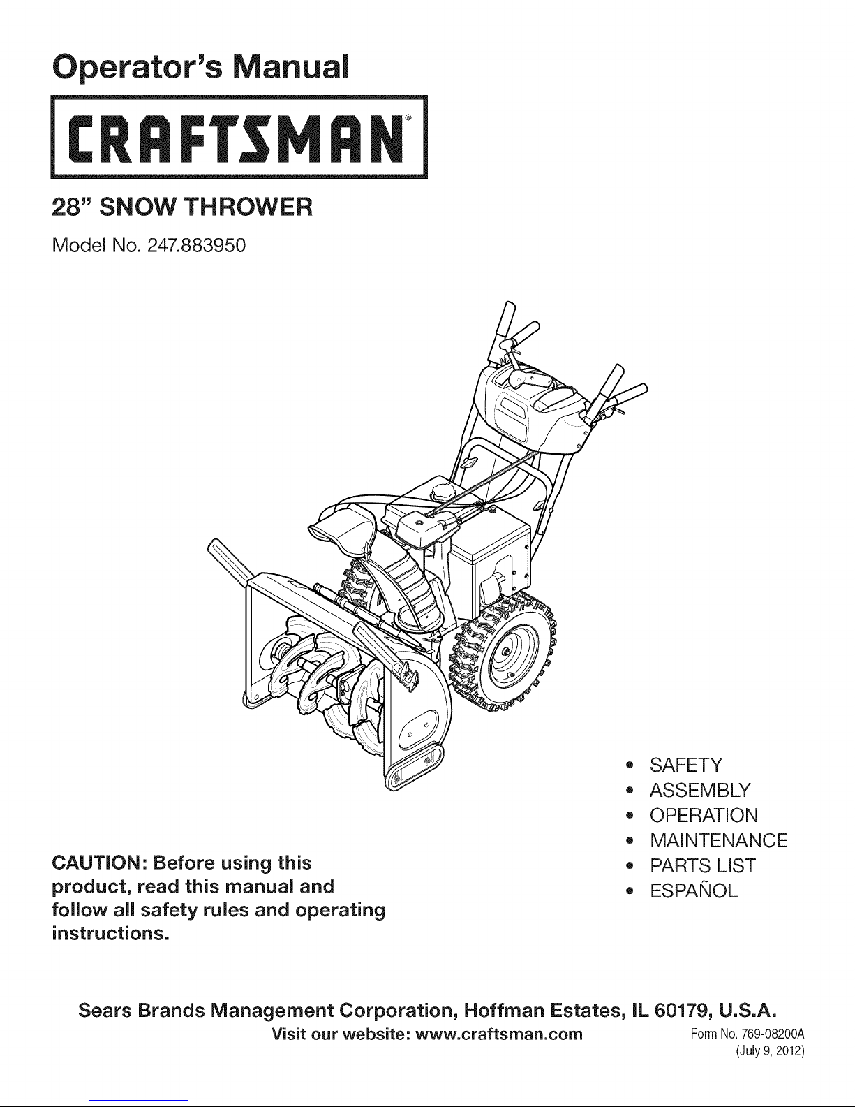
Operator's Manual
CRRFr MRN
28" SNOW THROWER
Model No. 247.883950
CAUTION" Before using this
product, read this manual and
follow all safety rules and operating
instructions.
Sears Brands Management Corporation, Hoffman Estates, IL 60179, U.S.A.
Visit our website: www.craftsman.com FormNo.769-08200A
,, SAFETY
o ASSEMBLY
OPERATION
MAINTENANCE
PARTS LIST
o ESPANOL
(July9,2012)
Page 2
WarrantyStatement.................... Page2
SafeOperationPractices.............. Pages3-6
Assembly......................... Pages8-13
Operation........................ Pages14-17
Service&Maintenance.............. Pages18-23
Troubleshooting...................... Page25
PartsList......................... Pages26-40
RepairProtectionAgreement............ Page45
Espa_ol............................. Page46
ServiceNumbers................... BackPage
Off-SeasonStorage................... Page24
CRAFTSMANTWOYEARFULLWARRANTY
FORTWOYEARSfromthedateofpurchase,thisproductiswarrantedagainstanydefectsinmaterialorworkmanship.Defectiveproductwill
receivefreerepairorfreereplacementifrepairisunavailable.
ADDiTiONAL LiFETiME LiMiTED WARRANTY on UPPER and LOWER CHUTE
FORAS LONGASITIS USEDbythe originalownerafterthe secondyearfromthedateof purchase,theupperandlowerchuteof this snow
throwerarewarrantedagainstany defectsinmaterialorworkmanshipasverifiedby a Searsauthorizedserviceprovider.Withproofof purchase,
youwill receivea newchutefreeof charge.Youare responsibleforthe laborcostof installationandany costincurredtoverify thedefect.
Forwarrantycoveragedetailsto obtainrepairor replacement,visittheweb site:www.craftsman.com
ThiswarrantycoversONLYdefectsinmaterialandworkmanship.WarrantycoveragedoesNOTinclude:
• Expendableitemsthatcanwearoutfromnormalusewithinthewarrantyperiod,includingbut notlimitedto augers,augerpaddles,drift
cutters,skidshoes,shaveplate,shearpins,sparkplug,aircleaner,belts,andoilfilter.
• Standardmaintenanceservicing,oilchanges,or tune-ups.
Tirereplacementor repaircausedbypuncturesfromoutsideobjects,suchasnails,thorns,stumps,orglass.
• Tireor wheelreplacementor repairresultingfromnormalwear,accident,orimproperoperationor maintenance.
Repairsnecessarybecauseof operatorabuse,includingbutnotlimitedto damagecausedbyover-speedingtheengine,or fromimpacting
objectsthatbendthe frame,augershaft,etc.
• Repairsnecessarybecauseof operatornegligence,includingbut notlimitedto,electricalandmechanicaldamagecausedbyimproper
storage,failureto usethe propergradeandamountofengineoil, or failureto maintaintheequipmentaccordingtotheinstructionscontained
intheoperator'smanual.
• Engine(fuelsystem)cleaningor repairscausedbyfueldeterminedto becontaminatedoroxidized(stale).ingeneral,fuel shouldbeused
within30 daysof itspurchasedate.
Normaldeteriorationandwearof theexteriorfinishes,orproductlabelreplacement.
Thiswarrantyisvoidif thisproductisever usedwhileprovidingcommercialservicesorif rentedtoanotherperson.
Thiswarrantygivesyouspecificlegalrights,andyou mayalsohaveotherrightswhichvaryfromstatetostate.
Sears Brands Management Corporation, Hoffman Estates, IL 60179
EngineOilType: SAE5W-30
EngineOilCapacity: 37ounces
FuelCapacity: Approx.5Quarts
SparkPlug: F6RTC(951-10292)
SparkPlugGap: .020"to .030"
©SearsBrands,LLC
ModelNumber.................................................................
Serial Number.................................................................
Dateof Purchase.............................................................
Recordthemodelnumber,serialnumber
anddateof purchaseabove
2
Page 3
Thissymbolpointsout importantsafetyinstructionswhich,if not
followed,couldendangerthepersonalsafetyand/orpropertyof
yourselfandothers. Readandfollowall instructionsin thismanual
beforeattemptingto operatethismachine.Failuretocomplywith
theseinstructionsmayresultin personalinjury.Whenyou seethis
symbol,HEEDITSWARNING!
Thismachinewasbuiltto beoperatedaccordingtothesafeopera-
tionpracticesinthis manual.Aswithanytypeof powerequipment,
carelessnessorerroron the partof theoperatorcanresultin serious
injury.Thismachineiscapableofamputatingfingers,hands,toes
andfeetandthrowingdebris.Failuretoobservethefollowingsafety
instructionscouldresultin seriousinjuryor death.
CALIFORNIA PROPOSITION 65
EngineExhaust,someof itsconstituents,andcertainvehicle
componentscontainoremitchemicalsknowntoStateofCalifornia
tocausecancerandbirthdefectsorotherreproductiveharm,
TRAiNiNG
• Read,understand,andfollowall instructionsonthe machineand
in themanual(s)beforeattemptingtoassembleandoperate.
Failuretodo socan resultinseriousinjurytotheoperatorand/
orbystanders.Keepthismanualin a safeplaceforfutureand
regularreferenceandfororderingreplacementparts.
• Befamiliarwithall controlsandtheirproperoperation.Knowhow
tostopthe machineanddisengagethemquickly.
• Neverallowchildrenunder14yearsof agetooperatethis
machine.Children14andovershouldreadandunderstandthe
instructionsandsafeoperationpracticesin thismanualandon
themachineandbe trainedandsupervisedbyanadult.
Neverallowadultsto operatethismachinewithoutproper
instruction.
• Thrownobjectscancauseseriouspersonalinjury.Planyour
snow-throwingpatterntoavoiddischargeof materialtoward
roads,bystandersandthelike.
Keepbystanders,petsandchildrenat least75feetfromthe
machinewhileitisinoperation.Stopmachineif anyoneenters
thearea.
• Exercisecautiontoavoidslippingorfalling,especiallywhen
operatinginreverse.
Your Responsibility--Restrict theuse ofthispowermachineto
personswhoread,understandandfollowthewarningsandinstruc-
tionsin thismanualandon the machine,
SAVE THESE INSTRUCTIONS!
PREPARATION
Thoroughlyinspecttheareawheretheequipmentistobeused.
Removeall doormats,newspapers,sleds,boards,wiresandother
foreignobjects,whichcouldbe trippedoverorthrownbytheauger/
impeller.
• Alwayswearsafetyglassesor eyeshieldsduringoperationand
whileperformingan adjustmentor repairto protectyoureyes.
Thrownobjectswhichricochetcancauseseriousinjurytothe
eyes.
Donot operatewithoutwearingadequatewinteroutergarments.
Donot wearjewelry,longscarvesorotherlooseclothing,which
couldbecomeentangledin movingparts.Wearfootwearwhich
willimprovefootingonslipperysurfaces.
Usea groundedthree-wireextensioncordand receptacleforall
machineswithelectricstartengines.
Disengageall controlleversbeforestartingtheengine.
Adjustcollectorhousingheighttocleargravelorcrushedrock
surfaces.
• Neverattemptto makeanyadjustmentswhileengineis running,
exceptwherespecificallyrecommendedintheoperator'smanual.
Letengineandmachineadjustto outdoortemperaturebefore
startingtoclearsnow.
3
Page 4
SafeHandling of Gasoline
Toavoidpersonalinjuryor propertydamageuseextremecarein
handlinggasoline.Gasolineisextremelyflammableandthevaporsare
explosive.Seriouspersonalinjurycanoccurwhengasolineis spilled
onyourselforyourclotheswhichcan ignite. Washyourskinand
changeclothesimmediately.
• Useonlyan approvedgasolinecontainer.
• Extinguishallcigarettes,cigars,pipesandother sourcesof
ignition.
• Neverfuel machineindoors.
• Neverremovegascapor addfuel whilethe engineishot or
running.
• Allowenginetocoolat leasttwo minutesbeforerefueling.
• Neveroverfillfueltank.Fill tankto nomorethan1/2inchbelow
bottomoffillerneckto providespaceforfuelexpansion.
• Replacegasolinecapandtightensecurely.
• Ifgasolineisspilled,wipe itoff theengineandequipment.Move
machinetoanotherarea.Wait5minutesbeforestartingthe
engine.
• Neverstorethe machineorfuelcontainerinsidewherethereisan
openflame,sparkor pilotlight(e.g.furnace,waterheater,space
heater,clothesdryeretc.).
• Allowmachinetocoolatleast5minutesbeforestoring.
• Neverfill containersinsidea vehicleor ona truckortrailerbed
witha plasticliner.Alwaysplacecontainersonthe groundaway
fromyourvehiclebeforefilling.
• If possible,removegas-poweredequipmentfromthe truckor
trailerandrefuelitonthe ground.Ifthis is notpossible,thenrefuel
suchequipmenton a trailerwitha portablecontainer,ratherthan
froma gasolinedispensernozzle.
• Keepthe nozzlein contactwiththerimofthe fueltankor
containeropeningatalltimesuntilfuelingiscomplete.Donot use
a nozzlelock-opendevice.
OPERATION
• Do notputhandsorfeetnear rotatingparts,in theauger/impeller
housingorchuteassembly.Contactwiththerotatingpartscan
amputatehandsandfeet.
• Theauger/impellercontrolleveris a safetydevice.Neverbypass
itsoperation.Doingsomakesthe machineunsafeandmaycause
personalinjury.
• Thecontrolleversmustoperateeasilyin bothdirectionsand
automaticallyreturntothe disengagedpositionwhenreleased.
• Neveroperatewitha missingordamagedchuteassembly.Keep
all safetydevicesinplaceandworking.
• Neverrunanengineindoorsor ina poorlyventilatedarea.Engine
exhaustcontainscarbonmonoxide,anodorlessanddeadlygas.
• Do notoperatemachinewhileundertheinfluenceof alcoholor
drugs.
• Mufflerandenginebecomehotandcan causea burn.Do not
touch.Keepchildrenaway.
• Exerciseextremecautionwhenoperatingonorcrossinggravel
surfaces.Stayalertforhiddenhazardsortraffic.
Exercisecautionwhenchangingdirectionandwhileoperatingon
slopes.Do notoperateon steepslopes.
Planyoursnow-throwingpatternto avoiddischargetowards
windows,walls,carsetc.Thus,avoidingpossibleproperty
damageorpersonalinjurycausedby a ricochet.
Neverdirectdischargeat children,bystandersand petsor allow
anyoneinfrontof themachine.
Donot overloadmachinecapacityby attemptingtoclearsnowat
toofastof a rate.
Neveroperatethismachinewithoutgoodvisibilityorlight.Always
be sureof yourfootingand keepa firmholdon thehandles.Walk,
neverrun.
Disengagepowerto theauger/impellerwhentransportingor not
in use.
Neveroperatemachineathightransportspeedson slippery
surfaces.Lookdownand behindandusecarewhenbackingup.
Ifthemachineshouldstartto vibrateabnormally,stopthe engine,
disconnectthesparkplugwireandgrounditagainsttheengine.
Inspectthoroughlyfor damage.Repairanydamagebefore
startingandoperating.
Disengageall controlleversandstopenginebeforeyouleave
theoperatingposition(behindthehandles).Waituntiltheauger/
impellercomestoa completestopbeforeuncloggingthechute
assembly,makingany adjustments,or inspections.
Neverputyourhandinthedischargeor collectoropenings.Do
notunclogchuteassemblywhileengineis running.Shutoff
engineand remainbehindhandlesuntilall movingpartshave
stoppedbeforeunclogging.
Useonlyattachmentsandaccessoriesapprovedbythemanufac-
turer(e.g.wheelweights,tirechains,cabsetc.). Forinformation
concerningtheseitems,call1-800-469-4663.
Whenstartingengine,pullcord slowlyuntilresistanceisfelt,then
pull rapidly.Rapidretractionofstartercord(kickback)will pull
handandarmtowardenginefasterthanyoucanletgo.Broken
bones,fractures,bruisesorsprainscouldresult.
Ifsituationsoccurwhichare notcoveredinthismanual,usecare
andgoodjudgment.
Toorderpartsor scheduleserviceforthisproduct,call 1-800-
469-4663.
CLEARING A CLOGGED DISCHARGE CHUTE
Handcontactwiththe rotatingimpellerinsidethe dischargechute
is the mostcommoncauseofinjuryassociatedwithsnowthrowers.
Neveruseyourhandtocleanoutthedischargechute.
Toclear thechute:
1. SHUTTHEENGINEOFF!
2. Wait 10secondstobe surethe impellerbladeshavestopped
rotating.
3. Alwaysusea clean-outtool,notyourhands.
4
Page 5
MAINTENANCE & STORAGE
• Nevertamperwithsafetydevices.Checktheirproperoperation
regularly.Refertothemaintenanceandadjustmentsectionsof
thismanual.
• Beforecleaning,repairing,or inspectingmachinedisengageall
controlleversandstoptheengine.Waituntilthe auger/impeller
cometoa completestop.Disconnectthe sparkplugwireand
groundagainsttheengineto preventunintendedstarting.
Checkboltsand screwsforpropertightnessatfrequentintervals
tokeepthemachineinsafeworkingcondition.Also,visually
inspectmachineforanydamage.
Donotchangetheenginegovernorsettingor over-speedthe
engine.Thegovernorcontrolsthe maximumsafeoperatingspeed
ofthe engine.
Snowthrowershaveplatesandskidshoesaresubjecttowear
anddamage.Foryoursafetyprotection,frequentlycheckall
componentsand replacewithoriginalequipmentmanufacturer's
(OEM)partsonlyaslistedinthe Partspagesof thisoperator's
manual.Useofpartswhichdonot meettheoriginalequipment
specificationsmayleadto improperperformanceandcompro-
misesafety!
Checkcontrolleversperiodicallytoverifytheyengageanddisen-
gageproperlyandadjust,ifnecessary.Refertotheadjustment
sectioninthisoperator'smanualfor instructions.
Maintainor replacesafetyandinstructionlabels,asnecessary.
Observeproperdisposallawsand regulationsforgas,oil,etc.to
protecttheenvironment.
Priorto storing,runmachinea few minutestoclearsnowfrom
machineand preventfreezeupof auger/impeller.
Neverstorethemachineorfuel containerinsidewherethereisan
openflame,sparkorpilot lightsuchas a waterheater,furnace,
clothesdryeretc.
Alwaysrefertothe operator'smanualforproperinstructionson
off-seasonstorage.
Checkfuelline,tank, cap,andfittingsfrequentlyfor cracksor
leaks.Replaceif necessary.
Donotcrankenginewithsparkplugremoved.
AccordingtotheConsumerProductsSafetyCommission(CPSC)
andtheU.S.EnvironmentalProtectionAgency(EPA),thisproduct
hasan AverageUsefulLifeof seven(7)years,or 60 hoursof
operation.AttheendoftheAverageUsefulLifehavethe machine
inspectedannuallybyanauthorizedservicedealerto ensurethat
allmechanicalandsafetysystemsareworkingproperlyand not
wornexcessively.Failuretodo so canresultinaccidents,injuries
ordeath.
DO NOT MODIFY ENGINE
Toavoidseriousinjuryor death,do not modifyengineinany way.
Tamperingwiththegovernorsettingcanleadtoa runawayengineand
causeitto operateat unsafespeeds.Nevertamperwithfactorysetting
ofenginegovernor.
NOTICE REGARDING EMiSSiONS
EngineswhicharecertifiedtocomplywithCaliforniaandfederal
EPAemissionregulationsforSORE(SmallOff RoadEquipment)are
certifiedto operateonregularunleadedgasoline,and mayinclude
thefollowingemissioncontrolsystems:EngineModification(EM),
OxidizingCatalyst(OC),SecondaryAirInjection(SAI)and ThreeWay
Catalyst(TWO)if soequipped.
SPARK ARRESTOR
Thismachineisequippedwithaninternalcombustionengineand
shouldnotbe usedonor nearany unimprovedforest-covered,
brush-coveredorgrass-coveredlandunlessthe engine'sexhaust
systemisequippedwitha sparkarrestormeetingapplicablelocalor
statelaws(if any)
Ifa sparkarrestorisused,it shouldbe maintainedin effectiveworking
orderbytheoperator.Inthe StateofCaliforniatheaboveisrequired
bylaw (Section4442ofthe CaliforniaPublicResourcesCode).Other
statesmayhavesimilarlaws. Federallawsapplyonfederallands.
A sparkarrestorforthemufflerisavailablethroughyournearestSears
PartsandRepairServiceCenter.
Page 6
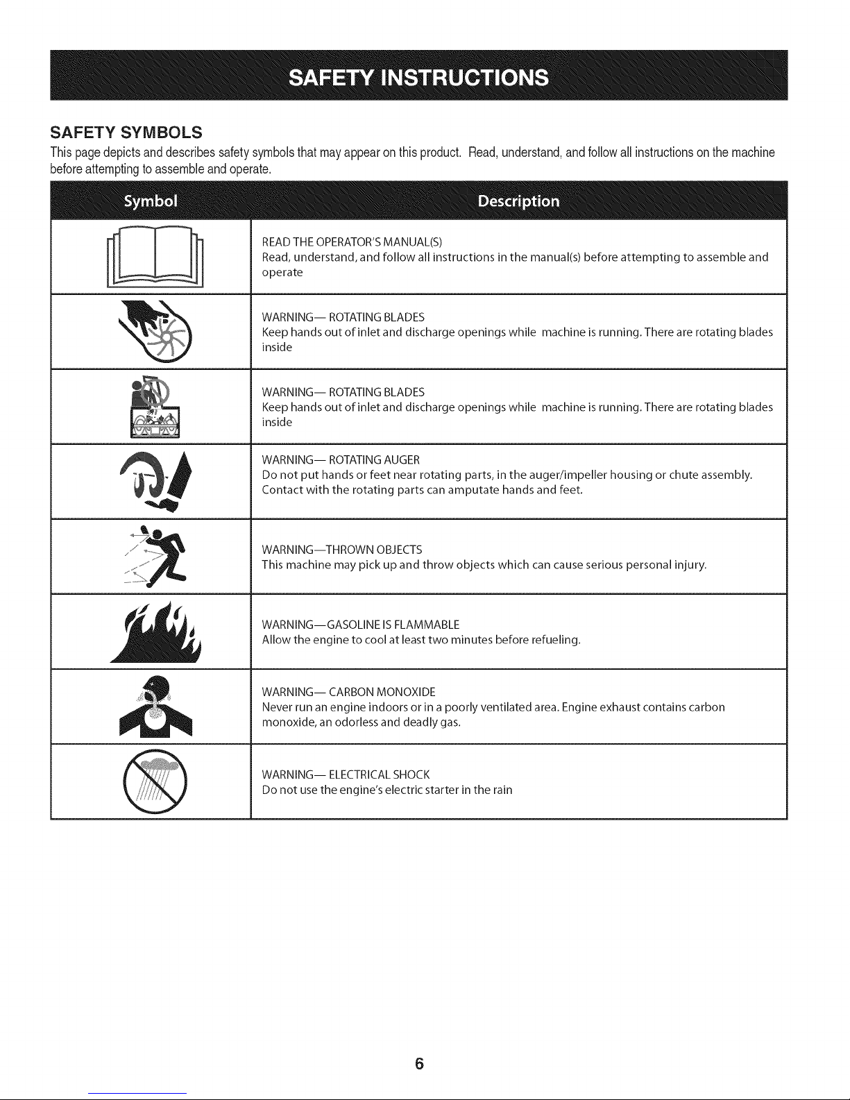
SAFETY SYMBOLS
Thispagedepictsanddescribessafetysymbolsthatmayappearonthisproduct. Read,understand,andfollowall instructionson the machine
beforeattemptingto assembleandoperate.
READ THE OPERATOR'S MANUAL(S)
i
. +
i
Read, understand, and follow all instructions in the manual(s) before attempting to assemble and
operate
WARNING-- ROTATING BLADES
Keep hands out of inlet and discharge openings while machine is running. There are rotating blades
inside
WARNING-- ROTATING BLADES
Keep hands out of inlet and discharge openings while machine is running. There are rotating blades
inside
WARNING-- ROTATING AUGER
Do not put hands or feet near rotating parts, in the auger/impeller housing or chute assembly.
Contact with the rotating parts can amputate hands and feet.
"JIp
WARNING--THROWN OBJECTS
This machine may pick up and throw objects which can cause serious personal injury.
WARNING--GASOLINE ISFLAMMABLE
Allow the engine to cool at least two minutes before refueling.
WARNING-- CARBON MONOXIDE
Never run an engine indoors or in a poorly ventilated area. Engine exhaust contains carbon
monoxide, an odorless and deadly gas+
WARNING-- ELECTRICAL SHOCK
Do not use the engine's electric starter in the rain
6
Page 7

Thispageleftintentionallyblank.
7
Page 8
NOTE:Referencesto rightorleftsideofthesnowthrowerare
determinedfrombehindtheunit intheoperatingposition(standing
directlybehindthesnowthrower,facingthe handlepanel).
REMOVING FROM CARTON
1. Cutthecornersof thecartonandlaythesidesflaton theground.
Removeanddiscardallpackinginserts.
2. Movethesnowthrowerout ofthecarton.
3. Makecertainthecartonhas beencompletelyemptiedbefore
discardingit.
ASSEMBLY
1. Observethe lowerrearareaof thesnowthrowerto besureboth
cablesarealignedwith rollerguidesbeforepivotingthehandle
upward.
a. Placethe shiftleverin theF6position.
b. Pullupandbackon upperhandleasshownin Figure1.As
youare raisingthehandleupward,makesurethat bothends
ofthe centercablearepositionedproperlyinthebrackets.
Alignupperhandlewiththelowerhandle.
c. Tightenhandknobssecuringupperhandletolowerhandle.
Removeanddiscardany rubberbands,ifpresent.Theyare
forpackagingpurposesonly.
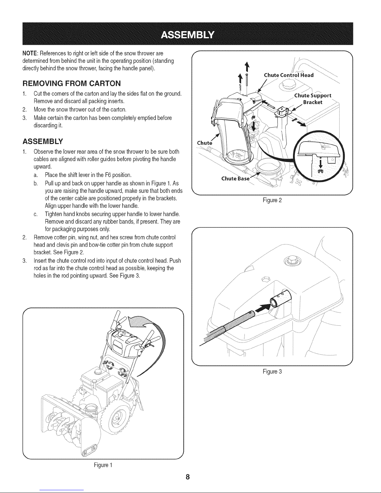
2. Removecotter pin,wingnut,and hexscrewfromchutecontrol
headandclevispinandbow-tiecotterpinfromchutesupport
bracket.See Figure2.
3. Insertthe chutecontrolrodintoinputofchutecontrolhead.Push
rodasfar intothe chutecontrolheadaspossible,keepingthe
holesinthe rodpointingupward.See Figure3.
t
Chute Control Head
Chute
Figure2
f
/
\
Figure1
Figure3
8
Page 9
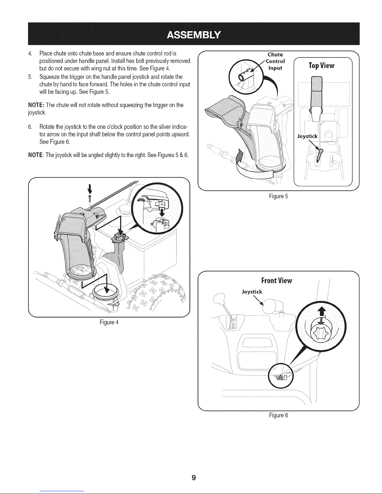
4. Placechuteontochutebaseandensurechutecontrolrodis
positionedunderhandlepanel.Installhex boltpreviouslyremoved
butdonot securewithwingnut atthistime.SeeFigure4.
5. Squeezethe triggeron thehandlepaneljoystickandrotatethe
chutebyhandto faceforward.Theholesinthechutecontrolinput
willbefacingup.SeeFigure5.
NOTE:The chutewillnot rotatewithoutsqueezingthe triggeronthe
joystick.
6. Rotatethejoystickto theoneo'clockpositionsothe silverindica-
torarrowon theinputshaftbelowthecontrolpanelpointsupward.
SeeFigure6.
NOTE:Thejoystickwillbeangledslightlyto theright.SeeFigures5 &6.
f Chute
Figure5
f "-,,
Figure4
f
FrontView
Joystick
J
Figure6
9
Page 10
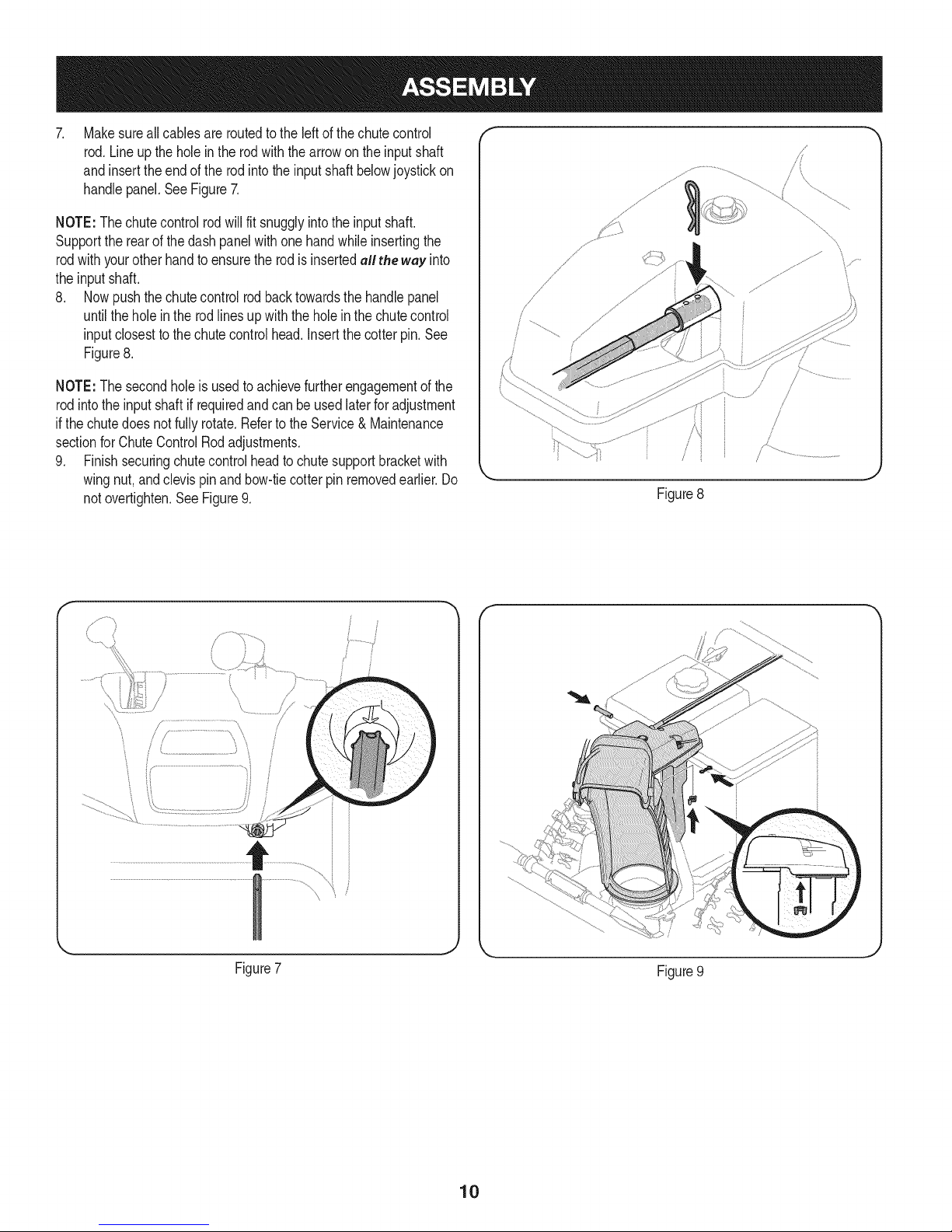
. Makesureallcablesareroutedtotheleftofthe chutecontrol
rod.Lineupthe holein therodwiththearrowon theinputshaft
and inserttheendof therodinto theinputshaftbelowjoystickon
handlepanel.SeeFigure7.
NOTE:Thechutecontrolrodwillfit snugglyintotheinputshaft.
Supporttherearofthedashpanelwithone handwhileinsertingthe
rodwithyourotherhandto ensuretherodis insertedell the way into
theinput shaft.
8. Nowpushthe chutecontrolrodbacktowardsthehandlepanel
untilthe holeinthe rodlines upwiththeholeinthechutecontrol
inputclosestto thechutecontrolhead. Insertthecotterpin.See
Figure8.
NOTE:The secondholeis usedtoachievefurtherengagementof the
rodintothe inputshaft ifrequiredandcan be usedlaterforadjustment
ifthe chutedoesnotfullyrotate.Referto theService& Maintenance
sectionforChuteControlRodadjustments.
9. Finishsecuringchutecontrolheadto chutesupportbracketwith
wingnut,andclevispinandbow-tiecotterpin removedearlier.Do
notovertighten.SeeFigure9.
/i _
Figure8
' .....................................................i_"i
Figure7
/
/
}
Figure9
10
Page 11
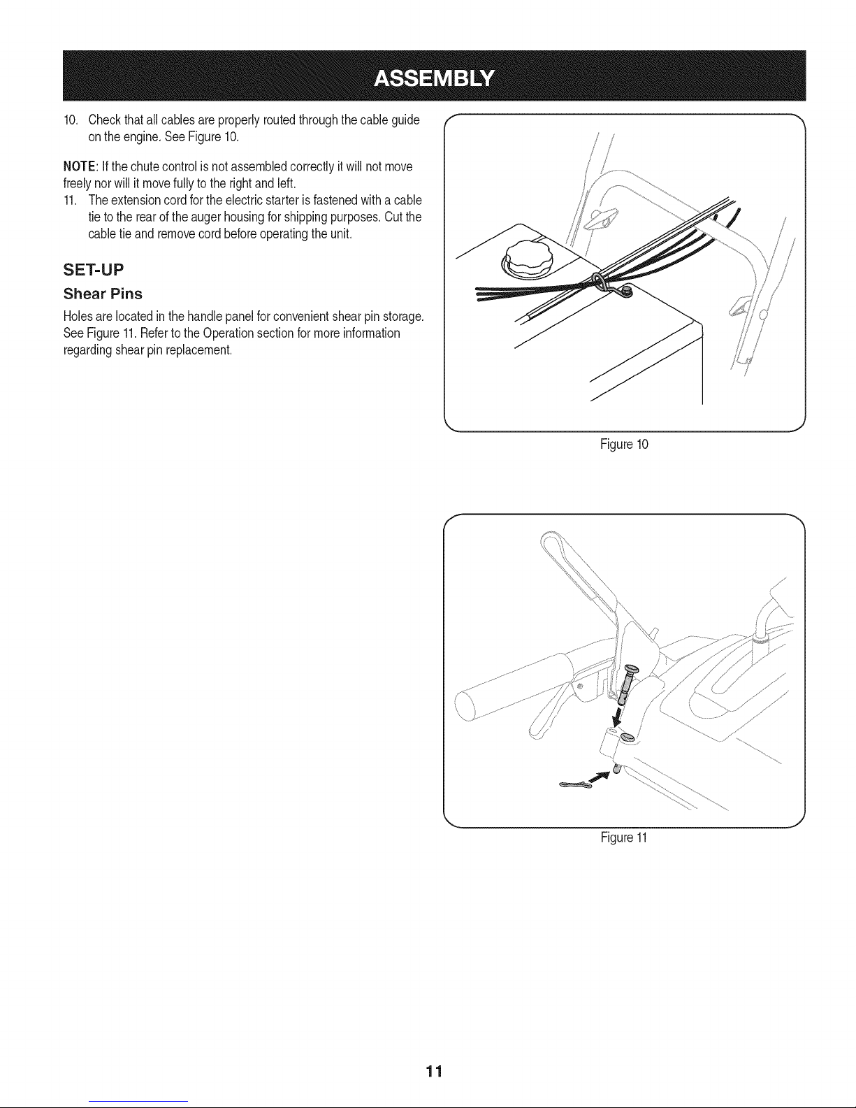
10. Checkthatall cablesare properlyroutedthroughthecable guide "_
ontheengine.SeeFigure10.
NOTE:Ifthe chutecontrolisnot assembledcorrectlyit willnot move
freelynorwillit movefullytotherightandleft.
11. Theextensioncordfor theelectricstarteris fastenedwitha cable
tieto therearof theaugerhousingforshippingpurposes.Cutthe
cabletie and removecordbeforeoperatingtheunit.
SET-UP
Shear Pins
Holesare locatedinthehandlepanelfor convenientshearpin storage.
SeeFigure11.Refertothe Operationsectionformoreinformation
regardingshearpinreplacement.
f
/
Figure10
J
Figure11
11
Page 12
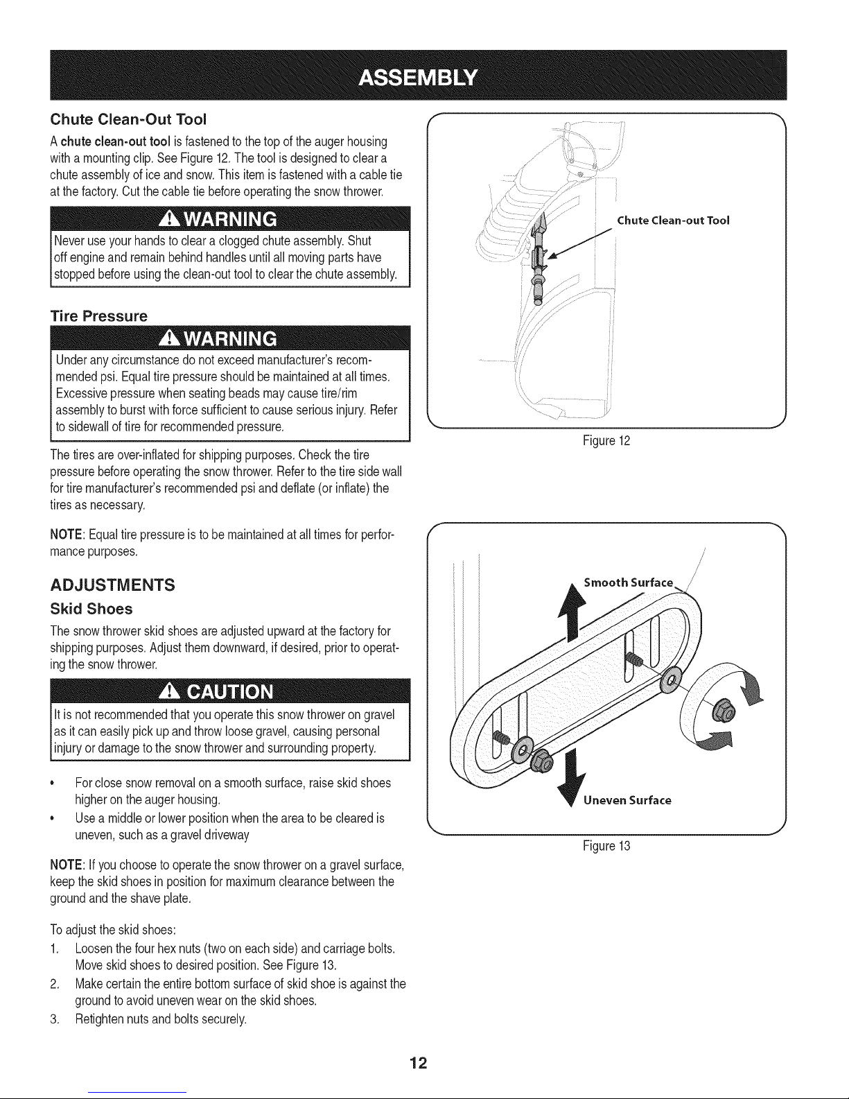
Chute Clean=Out Tool
Achute clean-out tool is fastenedtothetopoftheaugerhousing
witha mountingclip.SeeFigure12.The toolis designedtocleara
chuteassemblyofice andsnow.Thisitemis fastenedwitha cabletie
atthe factory.Cutthecabletie beforeoperatingthesnowthrower.
loft _1 .allmoving_oartshave
stoppedbeforeusingtheclean-outtooltoclearthechuteassembly.
Tire Pressure
Underanycircumstancedo notexceedmanufacturer'srecom-
mendedpsi.Equaltirepressureshouldbemaintainedat all times.
Excessivepressurewhenseatingbeadsmaycausetire/rim
assemblytoburstwithforcesufficientto causeseriousinjury.Refer
tosidewallof tirefor recommendedpressure.
Thetiresareover-inflatedforshippingpurposes.Checkthetire
pressurebeforeoperatingthesnowthrower.Refertothetiresidewall
fortiremanufacturer'srecommendedpsianddeflate(orinflate)the
tiresasnecessary.
//
Chute Clean-out Tool
Figure12
NOTE:Equaltire pressureistobe maintainedat alltimesfor perfor-
mancepurposes.
ADJUSTMENTS
Skid Shoes
Thesnowthrowerskidshoesareadjustedupwardatthefactoryfor
shippingpurposes.Adjustthemdownward,ifdesired,priortooperat-
ingthesnowthrower.
It isnot recommendedthatyouoperatethissnowthrowerongravel
asit caneasilypickup andthrowloosegravel,causingpersonal
[ njuryordamageto thesnowthrowerandsurroundng property.
• Forclosesnowremovalona smoothsurface,raiseskidshoes
higherontheaugerhousing.
• Usea middleor lowerpositionwhentheareato be clearedis
uneven,suchasagraveldriveway
NOTE:If youchooseto operatethesnowthrowerona gravelsurface,
keepthe skidshoesin positionformaximumclearancebetweenthe
groundandtheshaveplate.
Toadjustthe skidshoes:
1. Loosenthefourhexnuts(twooneachside)andcarriagebolts.
Moveskidshoestodesiredposition.SeeFigure13.
2. Makecertaintheentirebottomsurfaceof skidshoeisagainstthe
groundtoavoidunevenwearontheskidshoes.
3. Retightennutsand boltssecurely.
Smooth Surface
Uneven Surface
Figure13
12
Page 13
Priortooperatingyoursnowthrower,carefullyreadandfollowall
instructionsbelow.Performalladjustmentsto verifyyoursnow
throwerisoperatingsafelyandproperly.
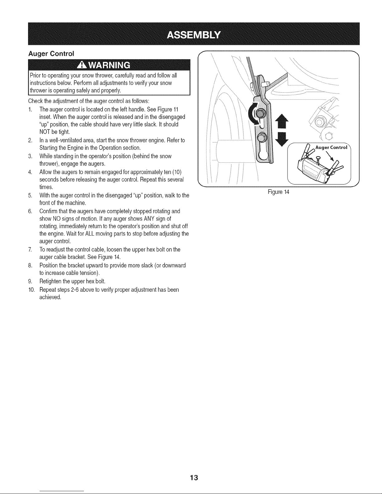
Checktheadjustmentoftheaugercontrolasfollows:
1. Theaugercontrolislocatedonthe left handle.SeeFigure11
inset.Whentheaugercontrolis releasedandin thedisengaged
"up"position,thecableshouldhaveverylittleslack.Itshould
NOTbetight.
2. Ina well-ventilatedarea,startthe snowthrowerengine.Referto
StartingtheEngineinthe Operationsection.
3. Whilestandinginthe operator'sposition(behindthe snow
thrower),engagethe augers.
4. Allowtheaugersto remainengagedforapproximatelyten (10)
secondsbeforereleasingthe augercontrol.Repeatthisseveral
times.
5. Withtheaugercontrolin thedisengaged"up" position,walktothe
frontofthe machine.
6. Confirmthatthe augershavecompletelystoppedrotatingand
showNOsignsof motion.IfanyaugershowsANYsignof
rotating,immediatelyreturntothe operator'spositionandshutoff
theengine.WaitforALLmovingpartsto stopbeforeadjustingthe
augercontrol.
7. Toreadjustthecontrolcable,loosentheupperhexboltonthe
augercablebracket.SeeFigure14.
8. Positionthebracketupwardtoprovidemoreslack(ordownward
toincreasecabletension).
9. Retightenthe upperhexbolt.
10. Repeatsteps2-6aboveto verifyproperadjustmenthasbeen
achieved.
I
i
J
Figure14
13
Page 14
f
Drive Control
ShiftLever
J
/ Four=WayChuteControP (Joystick)
Headlight
Gas C_
\
)...................AugerControl
-Wheel Steering ControJ
ChuteAssembly
\\
Drift Cutter
Recoil Starter
Handle
Auger
HOUSe,
CJeanOut
Tool
Muffler
\
Primer
Choke
Control Throt
Control
Augers _ SkidShoe Oil Drain
Figure15
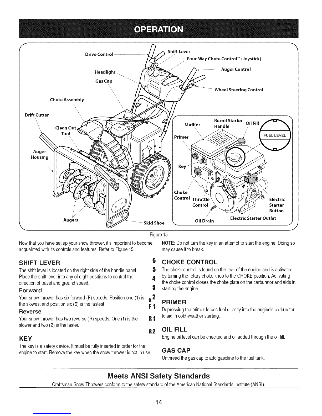
Nowthat youhavesetup yoursnowthrower,it'simportanttobecome NOTE:Donot turnthe keyinan attempttostarttheengine.Doingso
acquaintedwith itscontrolsandfeatures.Referto Figure15. maycauseit tobreak.
Oil Fill
,_J
SHIFT LEVER
Theshiftleveris locatedonthe rightsideof thehandlepanel.
Placethe shiftleverintoanyofeightpositionstocontrolthe
directionoftravelandgroundspeed.
Forward
Yoursnowthrowerhassixforward(F) speeds.Positionone(1)is t 2
theslowestandpositionsix(6) is thefastest. F 1
Reverse
Yoursnowthrowerhastwo reverse(R)speeds.One(1)is the
slowerandtwo(2) isthe faster.
KEY
Thekeyisa safetydevice.Itmustbefully insertedinorderfor the
enginetostart.Removethekeywhenthesnowthroweris notinuse.
Meets ANSi Safety Standards
CraftsmanSnowThrowersconformtothe safetystandardoftheAmericanNationalStandardsInstitute(ANSi).
6 CHOKE CONTROL
5 Thechokecontrolisfoundontherearoftheengineand isactivated
4 byturningtherotarychokeknobtotheCHOKEposition.Activating
thechokecontrolclosesthechokeplateon thecarburetorandaidsin
3 startingtheengine.
PRIMER
Depressingthe primerforcesfueldirectlyintotheengine'scarburetor
toaid incold-weatherstarting.
OIL FILL
Engineoil levelcanbecheckedandoiladdedthroughthe oil fill.
GAS CAP
Unthreadthegas capto add gasolinetothefuel tank.
14
Page 15
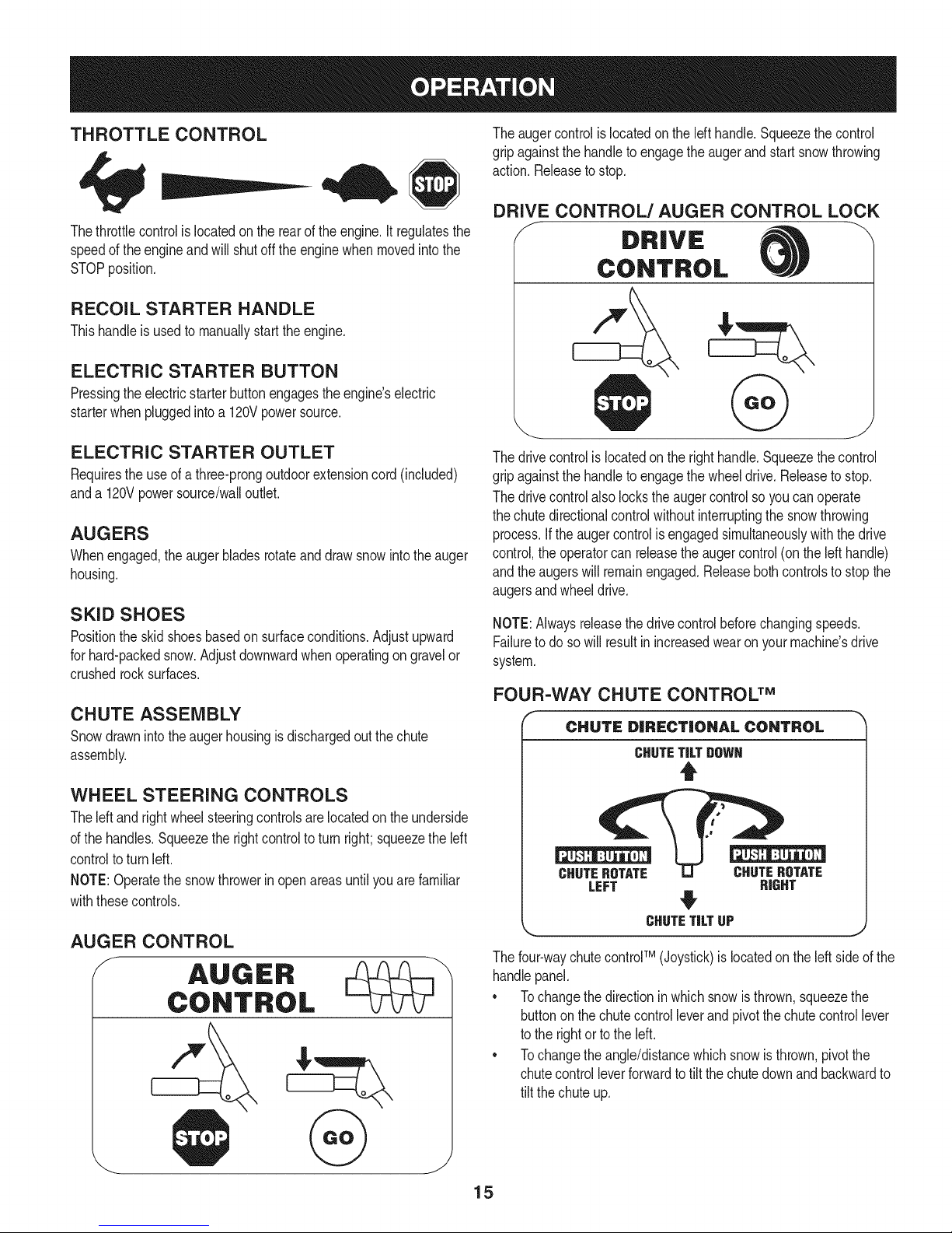
THROTTLE CONTROL
Thethrottlecontrolis locatedonthe rearofthe engine.It regulatesthe
speedof theengineandwill shutoff theenginewhenmovedintothe
STOPposition.
RECOIL STARTER HANDLE
Thishandleisusedto manuallystarttheengine.
ELECTRIC STARTER BUTTON
Pressingtheelectricstarterbuttonengagesthe engine'selectric
starterwhenpluggedintoa 120Vpowersource.
Theaugercontrolis locatedon thelefthandle.Squeezethecontrol
gripagainstthehandleto engagetheaugerand startsnowthrowing
action.Releaseto stop.
DRIVE CONTROL/AUGER CONTROL LOCK
DRIVE
CONTROL
ELECTRIC STARTER OUTLET
Requirestheuseof athree-prongoutdoorextensioncord(included)
anda 120Vpowersource/walloutlet.
AUGERS
Whenengaged,theaugerbladesrotateand drawsnowintothe auger
housing.
SKID SHOES
Positiontheskidshoesbasedon surfaceconditions.Adjustupward
forhard-packedsnow.Adjustdownwardwhenoperatingon gravelor
crushedrocksurfaces.
CHUTE ASSEMBLY
Snowdrawnintotheaugerhousingisdischargedoutthechute
assembly.
WHEEL STEERING CONTROLS
Theleft andrightwheelsteeringcontrolsarelocatedontheunderside
ofthe handles.Squeezethe rightcontrolto turnright;squeezetheleft
controltoturn left.
NOTE:Operatethesnowthrowerinopenareasuntilyouarefamiliar
withthesecontrols.
AUGER CONTROL
Thedrivecontrolis locatedonthe righthandle.Squeezethecontrol
gripagainstthehandleto engagethewheeldrive.Releasetostop.
Thedrivecontrolalsolockstheaugercontrolso youcan operate
thechutedirectionalcontrolwithoutinterruptingthesnowthrowing
process.If theaugercontrolisengagedsimultaneouslywiththedrive
control,the operatorcan releasetheaugercontrol(onthelefthandle)
andtheaugerswillremainengaged.Releaseboth controlstostopthe
augersandwheeldrive.
NOTE:Alwaysreleasethedrivecontrolbeforechangingspeeds.
Failureto dosowillresultinincreasedwearon yourmachine'sdrive
system.
FOUR-WAY CHUTE CONTROL TM
CHUTE DiRECTiONAl CONTROL
CHUTETiLTgOWN
t
CHUTEROTATE CHUTEROTATE
LEFT RIGHT
#
CHUTETiLTUP J
Thefour-waychutecontroFM(Joystick)is locatedon theleft sideofthe
handlepanel.
* Tochangethedirectioninwhichsnowis thrown,squeezethe
buttononthechutecontrolleverand pivotthechutecontrollever
tothe rightortotheleft.
* Tochangetheangle/distancewhichsnowisthrown,pivotthe
chutecontrolleverforwardto tiltthechutedownand backwardto
tilt thechuteup.
15
Page 16
CLEAN-OUT TOOL
Neveruseyourhandsto cleara cloggedchuteassembly.Shut
loft engineand remainbehindhandlesuntil allmovingpartshave
lstoppedbeforeusingtheclean-outtool toclearthechuteassembly.
Thechuteclean-outtoolisconvenientlyfastenedtotherearofthe
augerhousingwitha mountingclip.Shouldsnowandicebecome
lodgedin thechuteassemblyduringoperation,proceedasfollowsto
safelycleanthechuteassemblyandchuteopening:
1. Releaseboththe AugerControlandtheDriveControl.
2. Stopthe enginebyremovingtheignitionkey.
3. Removethe clean-outtoolfromthe clipwhichsecuresitto the
rearofthe augerhousing.
4. Usetheshovel-shapedendof theclean-outtooltodislodgeand
scoopanysnowand icewhichhasformedin andnearthechute
assembly.
5. Refastentheclean-outtoolto themountingclipontherearof
theaugerhousing,reinserttheignitionkeyandstartthesnow
thrower'sengine.
6. Whilestandinginthe operator'sposition(behindthesnow
thrower),engagethe augercontrolfora fewsecondstoclear any
remainingsnowandice fromthechuteassembly.
BEFORE STARTING ENGINE
Read,understand,andfollowall instructionsandwarningson the
machineand inthismanualbeforeoperating.
Oil
Theunit wasshippedwith oil inthe engine.Checkoillevelbefore
eachoperationtoensureadequateoilintheengine.Forfurther
instructions,refertothe stepsonpage18.
NOTE:Besuretochecktheengineon a levelsurfacewiththeengine
stopped.
1. Removethe oil fillercap/dipstickandwipethedipstickclean.
2. insertthe cap/dipstickintothe oilfillerneck,butdo NOTscrewit
in.
3. Removethe oil fillercap/dipstick,ifthe levelislow,slowlyadd
oil (5%30, witha minimumclassificationof SF/SG)untiloil level
registersbetweenhigh(H) andlow(L).
NOTE:Do notoverfill.Overfillingwithoil mayresultinenginesmoking,
hardstartingorsparkplugfouling.
4. Replaceandtightencap/dipstickfirmlybeforestartingengine.
Gasoline
Useautomotivegasoline(unleadedor low leadedtominimizecombus-
tionchamberdeposits)witha minimumof87octane.Gasolinewith
upto 10%ethanolor 15%MTBE(MethylTertiaryButylEther)canbe
used.Neveruseanoil/gasolinemixtureor dirtygasoline.Avoidgetting
dirt,dust,or waterinthefueltank. DONOTuse E85gasoline.
• Refuelina well-ventilatedareawiththeenginestopped.Donot
smokeorallowflamesor sparksin theareawheretheengineis
refueledor wheregasolineisstored.
• Donotoverfillthefueltank.After refueling,makesurethetank
capis closedproperlyandsecurely.
• Becarefulnotto spillfuelwhenrefueling.Spilledfuelorfuelvapor
mayignite,ifanyfuelisspilled,makesuretheareaisdrybefore
startingthe engine.
• Avoidrepeatedorprolongedcontactwithskinor breathingof
)or.
Useextremecarewhenhandlinggasoline.Gasolineisextremely
flammableandthevaporsare explosive.Neverfuelthemachine
indoorsorwhiletheengineis hotor running.Extinguishcigarettes,
cigars,pipesandothersourcesof ignition.
1. Cleanaroundfuelfill beforeremovingcap tofuel.
2. A fuellevelindicatorislocatedinthefueltank.SeeFigure15
inset.Becarefulnottooverfill.Filltank untilfuelreachesthefuel
levelindicatortoallowspacefor fuelexpansion.
STARTING THE ENGINE
Alwayskeephandsandfeetclearof movingparts.Donotusea
pressurizedstartingfluid.Vaporsareflammable.
NOTE:Allowtheengineto warmupfora fewminutesafter starting.
Theenginewill notdevelopfullpoweruntilit reachesoperating
temperatures.
1. Makecertainboththe augercontrolanddrivecontrolarein the
disengaged(released)position.
2. insertkeyintoslot. Makesureit snapsintoplace.Donotattempt
toturn thekey.
NOTE:Theenginecannotstartwithoutthekeyfullyinsertedintothe
ignitionswitch.
Electric Starter
Theoptionalelectricstarterisequippedwitha groundedthree-wire
powercordandplug,and is designedto operateon120voltAC
householdcurrent.It mustbeusedwitha properlygroundedthree-
prongreceptacleat all timesto avoidthe possibilityofelectricshock.
Followall instructionscarefullypriorto operatingtheelectricstarter.
DONOTuse electricstarterintherain.
Determinethatyourhome'swiringisa three-wiregroundedsystem.
Aska licensedelectricianifyouarenotcertain.
Ifyouhavea groundedthree-prongreceptacle,proceedasfollows.
Ifyoudonot havethe properhousewiring,DONOTusetheelectric
starterunderanyconditions.
1. Plugtheextensioncordintotheoutletlocatedon theengine's
surface.Plugtheotherendof extensioncordintoa three-prong
120-volt,grounded,ACoutletinawell-ventilatedarea.
16
Page 17
2. Movethrottlecontrolto FAST(rabbit)_J_" position.
3. Movechoketothe CHOKEI,'_1 position(coldenginestart).If
engineiswarm,placechokein RUNposition.
4. Pushprimerthree(3)times,makingsuretocoverventholein
primerbulbwhen pushing.If engineiswarm,pushprimeronly
once.Alwayscoverventholewhenpushing.Coolweathermay
requireprimingtobe repeated.
5. Pushstarterbuttontostart engine.Oncetheenginestarts,im-
mediatelyreleasestarterbutton.Electricstarterisequippedwith
thermaloverloadprotection;systemwilltemporarilyshut-downto
allowstartertocool ifelectricstarterbecomesoverloaded.
6. Astheenginewarms,slowlyrotatethe chokecontroltoRUN
position.Ifthe enginefalters,restartengineandrunwithchoke
athalf-chokepositionforashortperiodoftime,andthenslowly
rotatethechokeinto RUNposition.
7. Afterengineisrunning,disconnectpowercordfromelectric
starter.Whendisconnecting,alwaysunplugtheendatthewall
outletbeforeunpluggingtheoppositeendfromtheengine.
Recoil Starter
Donotpullthestarterhandlewhilethe enginerunning.
1. Movethrottlecontrolto FAST(rabbit)_J_ position.
2. Movechoketothe CHOKEI_¢1 position(coldenginestart).If
engineiswarm,placechokein RUNposition.
3. Pushprimerthree(3)times,makingsuretocoverventholewhen
pushing.Ifengineiswarm,pushprimeronlyonce.Alwayscover
ventholewhenpushing.Coolweathermayrequireprimingtobe
repeated.
4. Pullgentlyonthe starterhandleuntilitbeginstoresist,then
pullquicklyandforcefullytoovercomethe compression.Engine
shouldstart.Donotreleasethehandleandallowittosnapback.
ReturnropeSLOWLYto originalposition.If required,repeatthis
step.
5. Astheenginewarms,slowlyrotatethe chokecontroltoRUN
position.Ifthe enginefalters,restartengineandrunwithchoke
athalf-chokepositionforashortperiodoftime,andthenslowly
rotatethechokeinto RUNposition.
TO ENGAGE DRIVE
1. Withthe throttlecontrolinthe Fast(rabbit)position,moveshift
leverintooneofthe sixforward(F)positionsor tworeverse(R)
positions.Selecta speedappropriateforthesnowconditionsand
a paceyou'recomfortablewith.
NOTE:When selectinga DriveSpeed,usetheslowerspeedsuntil
youarecomfortableandfamiliarwiththe operationofthesnow
thrower.
2. Squeezethedrivecontrolagainstthehandleandthesnow
throwerwillmove.Releaseit anddrivemotionwillstop.
NOTE:NEVERrepositionthe shiftlever(changespeedsordirection
oftravel)withoutfirstreleasingthedrivecontrolandbringingthe snow
throwertoa completestop.Doingsowill resultin prematurewearto
thesnowthrower'sdrivesystem.
TO ENGAGE AUGERS
1. Toengagetheaugersandstartthrowingsnow,squeezethe
augercontrolagainstthelefthandle.Releasetostoptheaugers.
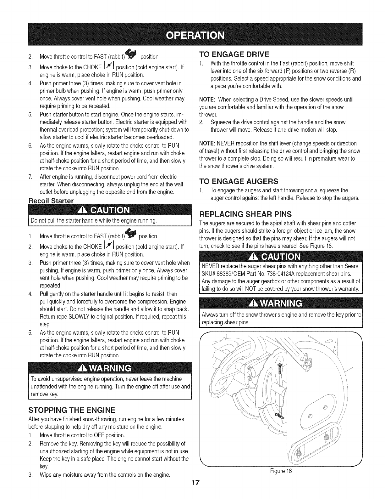
REPLACING SHEAR PiNS
Theaugersare securedtothespiralshaftwith shearpinsandcotter
pins.If theaugersshouldstrikeaforeignobjectorice jam,thesnow
throwerisdesignedsothatthe pinsmayshear.If theaugerswillnot
turn,checkto seeif thepins havesheared.SeeFigure16.
NEVERreplacetheaugershearpinswithanythingotherthanSears
SKU#88389/0EM PartNo.738-04124Areplacementshearpins.
Anydamagetotheaugergearboxorothercomponentsasa resultof
failingto do sowill NOTbecoveredbyyoursnowthrower'swarranty.
Alwaysturnoff thesnowthrower'sengineand removethekeypriorto
replacingshearpins.
Toavoidunsupervisedengineoperation,neverleavethemachine
unattendedwiththeenginerunning.Turntheengineoffafteruseand
removekey.
STOPPING THE ENGINE
Afteryouhavefinishedsnow-throwing,runenginefora few minutes
beforestoppingtohelpdryoffany moistureontheengine.
1. MovethrottlecontroltoOFFposition.
2. Removethekey.Removingthekeywillreducethepossibilityof
unauthorizedstartingoftheenginewhileequipmentisnotinuse.
Keepthekeyina safeplace.The enginecannotstartwithoutthe
key.
3. Wipeany moistureawayfromthe controlsontheengine.
Figure16
17
Page 18
MAINTENANCE SCHEDULE
Beforeperforminganytypeofmaintenance/service,disengageall
controlsandstoptheengine.Waituntilallmovingpartshavecometo
acompletestop.Disconnectsparkplugwireandgrounditagainstthe
enginetopreventunintendedstarting.Alwayswearsafetyglassesduring
operationorwhileperforminganyadjustmentsorrepairs.
EachUseandevery5
hours
1st5 hours
Annuallyor25 hours
Annuallyor50 hours
Annuallyor100hours
BeforeStorage
1. Engineoil level
2. Looseor missinghardware
3. Unitandengine.
1. Engineoil
1. Sparkplug
2. Controllinkagesandpivots
3. Wheels
4. GearshaftandAugershaft
1. Engineoil
1. Sparkplug
1. Fuelsystem
1. Check
2. Tightenor replace
3. Clean
1. Change
1. Check
2. Lubewithlightoil
3. Lubewithmultipurposeautogrease
4. Lubewithlightoil
1. Change
1. Change
1. Runengineuntilit stopsfromlack
ENGINE MAINTENANCE
Checking Engine Oil
Followthemaintenanceschedulegivenbelow.Thischartdescribes
serviceguidelinesonly.UsetheServiceLogcolumntokeeptrackof
completedmaintenancetasks.Tolocate the nearest Sears Service
Centeror to scheduleservice,simplycontactSearsat
1-800-4-MY-HOME®.
d fuel
Beforelubricating,repairing,or inspecting,disengageall controls
Iandstopengine.Waituntilall movingpartshavecometo a complete
_stop.
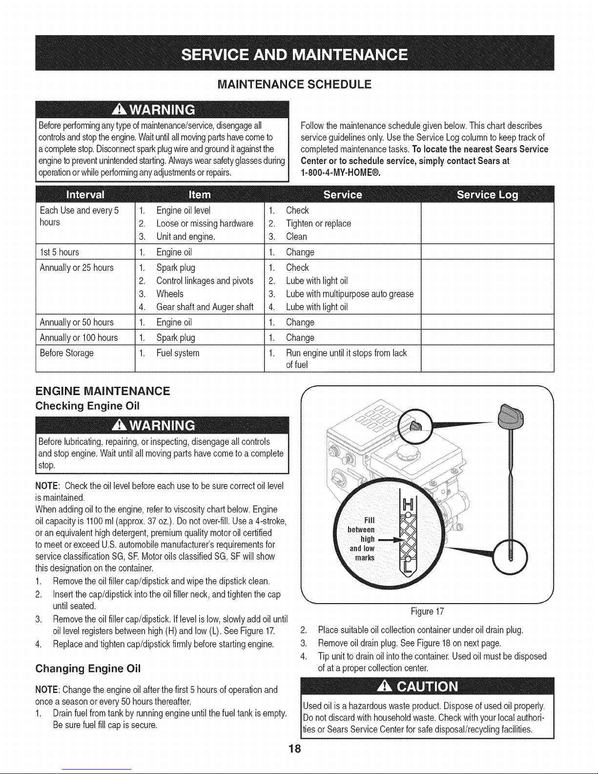
NOTE: Checktheoil levelbeforeeachuseto besurecorrectoil level
ismaintained.
Whenaddingoilto theengine,referto viscositychart below.Engine
oilcapacityis 1100ml(approx.37oz.).Donotover-fill.Usea 4-stroke,
oran equivalenthighdetergent,premiumqualitymotoroilcertified
tomeetorexceedU.S.automobilemanufacturer'srequirementsfor
serviceclassificationSG, SRMotoroilsclassifiedSG,SFwillshow
thisdesignationonthecontainer.
1. Removethe oil fillercap/dipstickandwipethedipstickclean.
2. Insertthe cap/dipstickintothe oilfillerneck,andtightenthecap
untilseated.
3. Removethe oil fillercap/dipstick.Iflevelis low,slowlyaddoiluntil
oil levelregistersbetweenhigh(H)andlow(L).SeeFigure17.
4. Replaceandtightencap/dipstickfirmlybeforestartingengine.
Changing Engine Oil
NOTE:Changetheengineoilafterthe first5 hoursof operationand
oncea seasonorevery50 hoursthereafter.
1. Drainfuelfromtankbyrunningengineuntilthefueltankisempty.
Besurefuel fillcap issecure.
J
Figure17
2. Placesuitableoilcollectioncontainerunderoil drainplug.
3. Removeoil drainplug.SeeFigure18on nextpage.
4. Tipunit todrainoil intothecontainer.Usedoilmustbedisposed
ofat a propercollectioncenter.
Usedoil isa hazardouswasteproduct.Disposeofusedoil properly.
IDo notdiscardwithhouseholdwaste.Checkwithyour localauthori-
lties or SearsServiceCenterforsafedisposal/recyclingfacilities.
18
Page 19
.
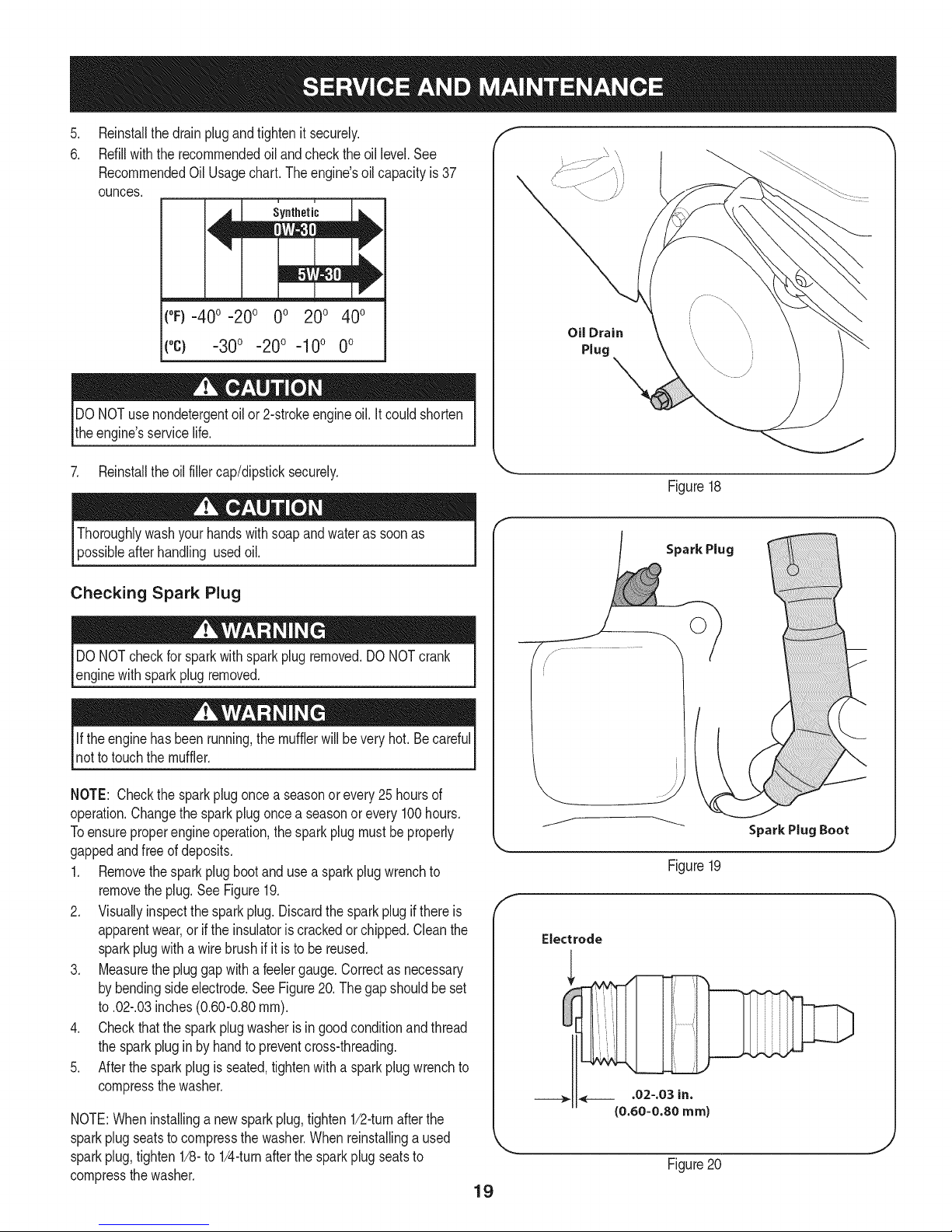
Reinstallthedrainplugandtightenit securely.
6.
Refillwiththerecommendedoil andcheckthe oil level.See
RecommendedOil Usagechart.Theengine'soilcapacityis37
ounces.
i u
[
(%-40 °-20 o 0o 200 400
("c) -300 -200 -10° 0°
DONOTuse nondetergentoilor 2-strokeengineoil.Itcouldshorten
theengine'sservicelife.
Oil Drain
Plug
7. Reinstalltheoilfillercap/dipsticksecurely.
Thoroughlywashyourhandswithsoap andwaterassoonas
possibleafterhandling usedoil.
Checking Spark Plug
DONOTcheckforsparkwithsparkplugremoved.DONOTcrank
enginewithsparkplug removed.
Iftheenginehas beenrunning,themufflerwillbeveryhot.Becareful
notto touchthemuffler.
NOTE: Checkthesparkplugoncea seasonorevery25hoursof
operation.Changethesparkplugoncea seasonor every100hours.
Toensureproperengineoperation,the sparkplugmustbe properly
gappedandfreeof deposits.
1. Removethesparkplugbootandusea sparkplugwrenchto
removetheplug.See Figure19.
2. Visuallyinspectthesparkplug.Discardthesparkplugifthereis
apparentwear,orif the insulatoriscrackedorchipped.Cleanthe
sparkplugwitha wirebrush ifit isto be reused.
3. Measurethepluggapwithafeelergauge.Correctas necessary
bybendingsideelectrode.SeeFigure20.Thegapshouldbeset
to.02-.03inches(0.60-0.80ram).
4. Checkthatthe sparkplugwasherisingoodconditionandthread
thesparkplugin by handtopreventcross-threading.
5. Afterthesparkplugis seated,tightenwitha sparkplugwrenchto
compressthewasher.
NOTE:Wheninstallinga newsparkplug,tighten1/2-turnafterthe
sparkplugseatsto compressthewasher.Whenreinstallinga used
sparkplug,tighten1/8-to 1/4-turnafterthe sparkplugseatsto
compressthewasher.
Figure18
Spark Plug
O
J
Figure19
Electrode
.02-.03 in.
{0.60-0.80 ram)
Figure20
19
Page 20
hotandcan ine.
LUBRICATION
Gear Shaft
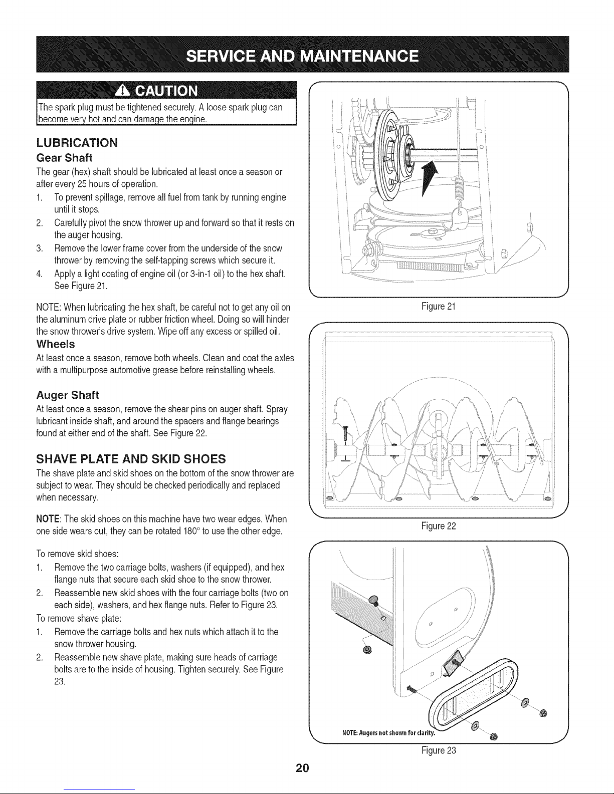
Thegear(hex)shaftshouldbe lubricatedatleastoncea seasonor
afterevery25 hoursofoperation.
1. Topreventspillage,removeall fuel fromtank byrunningengine
untilit stops.
2. Carefullypivotthesnowthrowerupandforwardsothat itrestson
theaugerhousing.
3. Removethe lowerframecoverfromtheundersideofthesnow
throwerbyremovingthe self-tappingscrewswhichsecureit.
4. Applya lightcoatingofengineoil (or3-in-1oil) to thehexshaft.
SeeFigure21.
NOTE:Whenlubricatingthehexshaft,be carefulnottogetanyoilon
thealuminumdriveplateor rubberfrictionwheel.Doingsowillhinder
thesnowthrower'sdrive system.Wipeoffanyexcessor spilledoil.
Wheels
Atleastoncea season,removebothwheels.Cleanandcoattheaxles
witha multipurposeautomotivegreasebeforereinstallingwheels.
Auger Shaft
Atleastoncea season,removethe shearpinson augershaft.Spray
lubricantinsideshaft,andaroundthe spacersandflangebearings
foundat eitherendof theshaft.SeeFigure22.
Figure21
O i
X" "?X
/ .... )
{;:7X
7/'................
)
SHAVE PLATE AND SKID SHOES
Theshaveplateand skidshoesonthebottomofthesnowthrowerare
subjecttowear.Theyshouldbecheckedperiodicallyandreplaced
whennecessary.
NOTE:Theskidshoeson thismachinehavetwowearedges.When
onesidewearsout,theycan be rotated1800to usetheotheredge.
Toremoveskidshoes:
1. Removethe twocarriagebolts,washers(ifequipped),andhex
flangenutsthat secureeachskidshoeto thesnowthrower.
2. Reassemblenewskidshoeswiththe fourcarriagebolts(twoon
eachside),washers,andhex flangenuts.RefertoFigure23.
Toremoveshaveplate:
1. Removethe carriageboltsand hexnutswhichattachit tothe
snowthrowerhousing.
2. Reassemblenewshaveplate,makingsureheadsofcarriage
boltsaretothe insideof housing.Tightensecurely.SeeFigure
23.
/
J
Figure22
f
Figure23
2O
Page 21
ADJUSTMENTS
Shift Cable
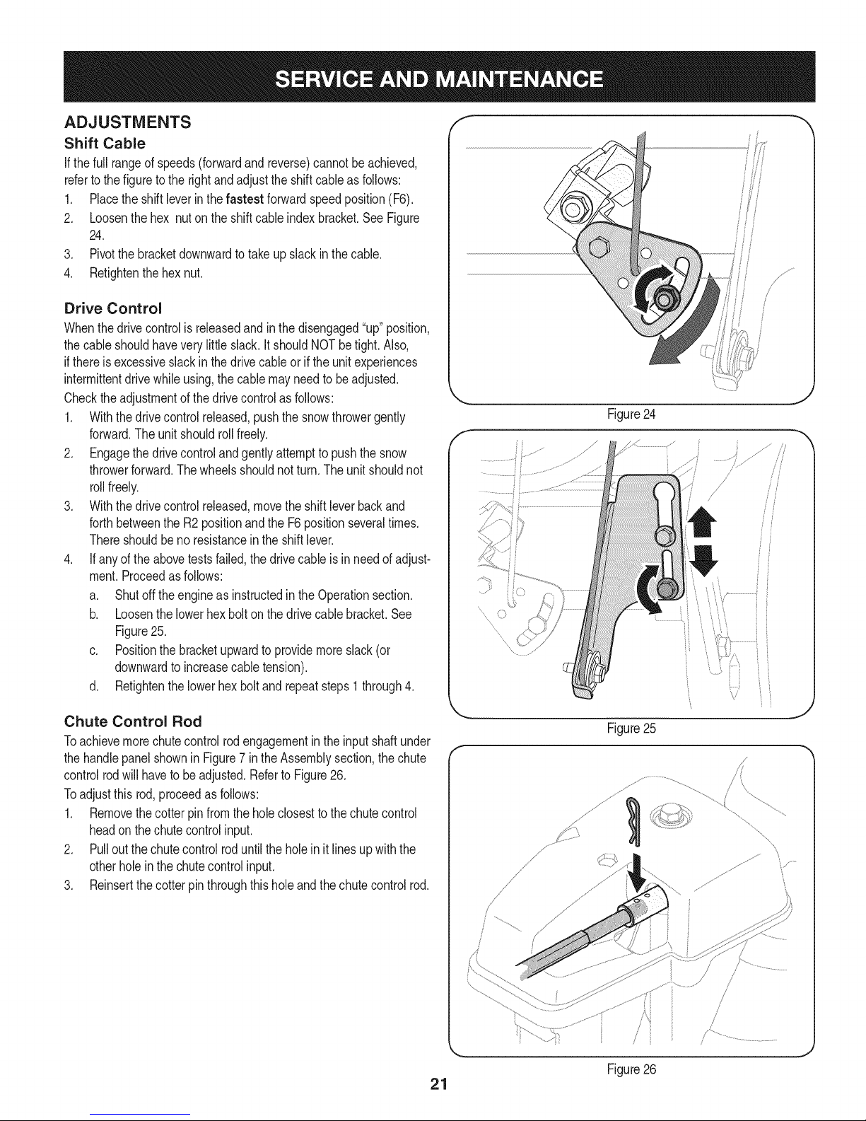
If thefull rangeofspeeds(forwardandreverse)cannotbe achieved,
referto thefiguretothe rightandadjustthe shiftcableasfollows:
1. Placetheshiftleverin thefastest forwardspeedposition(F6).
2. Loosenthehex nuton theshiftcableindexbracket.SeeFigure
24.
3. Pivotthebracketdownwardtotakeupslackinthecable.
4. Retightenthehexnut.
Drive Control
Whenthedrivecontrolis releasedandin thedisengaged"up"position,
thecableshouldhaveverylittle slack.It shouldNOTbetight. Also,
ifthereisexcessiveslackin thedrivecableor ifthe unitexperiences
intermittentdrivewhileusing,the cablemayneedto beadjusted.
Checktheadjustmentofthedrivecontrolasfollows:
1. Withthedrivecontrolreleased,pushthesnowthrowergently
forward.Theunitshouldrollfreely.
2. Engagethedrivecontrolandgentlyattempttopushthesnow
throwerforward.Thewheelsshouldnotturn.Theunitshouldnot
rollfreely.
3. Withthedrivecontrolreleased,movetheshiftleverbackand
forthbetweenthe R2positionandthe F6positionseveraltimes.
Thereshouldbeno resistancein theshiftlever.
4. If anyof theabovetestsfailed,thedrivecableisinneedofadjust-
ment.Proceedasfollows:
a. Shutoff theengineas instructedintheOperationsection.
b. Loosenthelowerhexboltonthedrivecablebracket.See
Figure25.
c. Positionthebracketupwardtoprovidemoreslack(or
downwardto increasecabletension).
d. Retightenthe lowerhex boltand repeatsteps1 through4.
J
f
.........
Chute Control Rod
Toachievemorechutecontrolrodengagementintheinputshaftunder
thehandlepanelshownin Figure7inthe Assemblysection,thechute
controlrodwillhavetobeadjusted.Referto Figure26.
Toadjustthis rod,proceedasfollows:
1. Removethecotterpin fromtheholeclosestto thechutecontrol
headon thechutecontrolinput.
2. Pulloutthe chutecontrolroduntilthe holein itlinesupwiththe
otherholeinthe chutecontrolinput.
3. Reinsertthecotterpinthroughthisholeandthechutecontrolrod.
21
Figure25
/
/ ,
Figure26
J
J
\
\
Page 22
Auger Control
Refertothe Assemblysectionforinstructionsonadjustingtheauger
controlcable.
Skid Shoes
Refertothe Assemblysectionforinstructionsonadjustingtheskid
shoes.
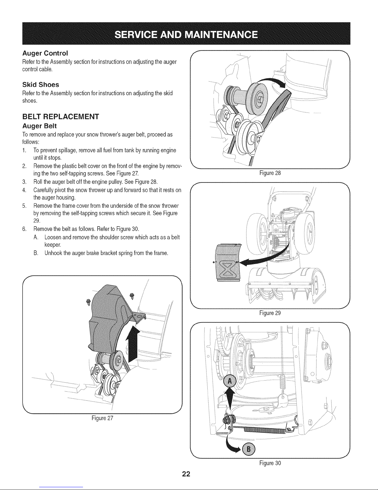
BELT REPLACEMENT
Auger Belt
Toremoveandreplaceyoursnowthrower'saugerbelt,proceedas
follows:
1. Topreventspillage,removeall fuel fromtank byrunningengine
untilitstops.
2. Removethe plasticbeltcoveronthefrontoftheenginebyremov-
ingthetwoself-tappingscrews.SeeFigure27.
3. Rollthe augerbeltoff theenginepulley.See Figure28.
4. Carefullypivotthesnowthrowerupandforwardsothat itrestson
theaugerhousing.
5. Removethe framecoverfromtheundersideofthesnowthrower
byremovingtheself-tappingscrewswhichsecureit.SeeFigure
29.
6. Removethe beltasfollows.RefertoFigure30.
A. Loosenand removetheshoulderscrewwhichactsas a belt
keeper.
B. Unhooktheaugerbrakebracketspringfromthe frame.
J
Figure28
f
J
Figure29
f
.....i
Figure27
_jz:.................
J
Figure30
22
Page 23
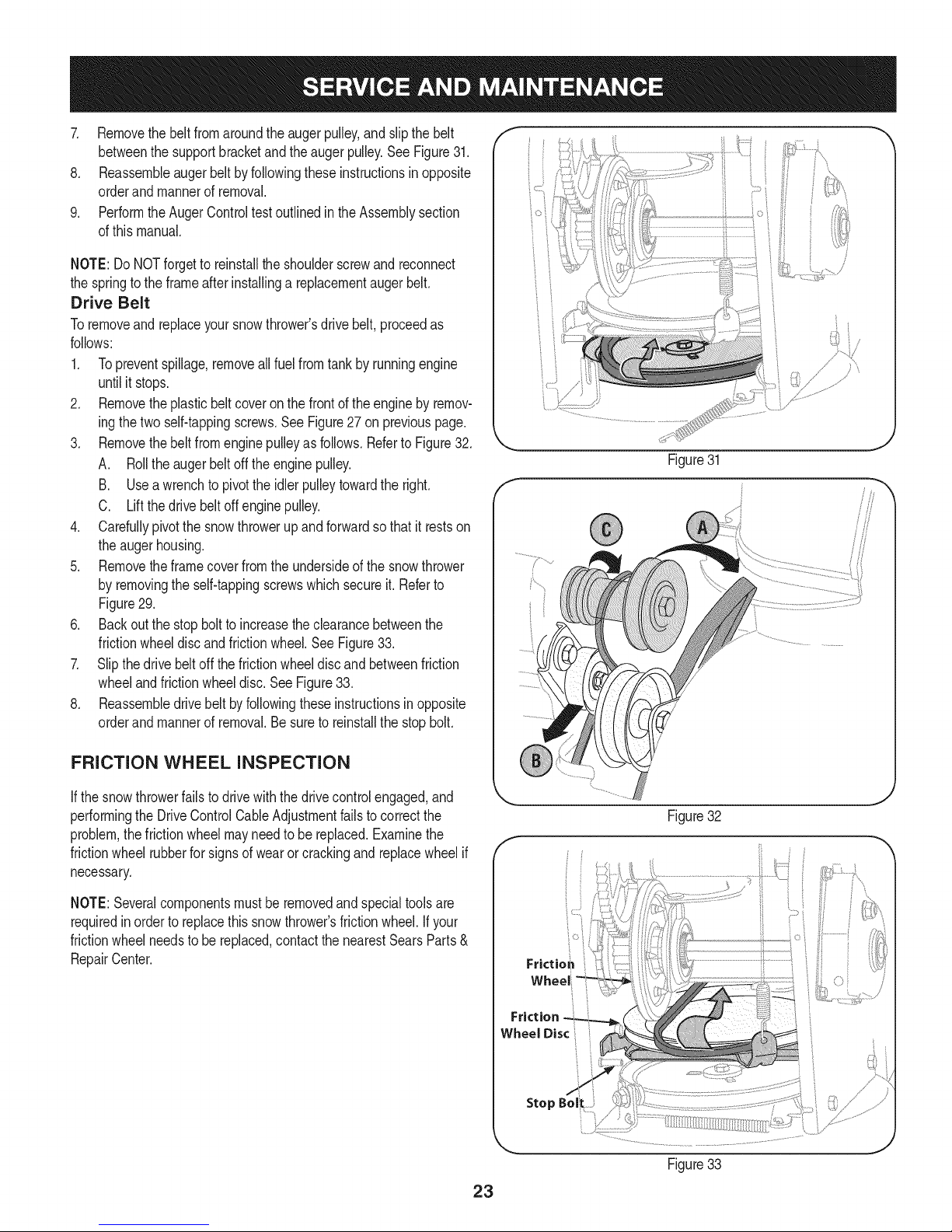
7. Removethebeltfromaroundtheaugerpulley,andslipthebelt
betweenthesupportbracketandtheaugerpulley.SeeFigure31.
8. Reassembleaugerbeltbyfollowingtheseinstructionsinopposite
orderandmannerofremoval.
9. PerformtheAugerControltestoutlinedintheAssemblysection
ofthismanual.
NOTE:DoNOTforgettoreinstalltheshoulderscrewandreconnect
thespringtotheframeafterinstallingareplacementaugerbelt.
Drive Belt
Toremoveandreplaceyoursnowthrower'sdrivebelt,proceedas
follows:
1. Topreventspillage,removeallfuelfromtankby runningengine
untilit stops.
2. Removetheplasticbelt coveronthefrontoftheenginebyremov-
ingthetwoself-tappingscrews.SeeFigure27on previouspage.
3. Removethebeltfromenginepulleyasfollows.RefertoFigure32.
A. Rolltheaugerbeltoff theenginepulley.
B. Useawrenchto pivottheidlerpulleytowardthe right.
C. Liftthedrivebeltoffenginepulley.
4. Carefullypivotthesnowthrowerupandforwardsothat itrestson
theaugerhousing.
5. Removetheframecoverfromtheundersideofthe snowthrower
byremovingtheself-tappingscrewswhichsecureit.Referto
Figure29.
6. Backoutthe stopboltto increasetheclearancebetweenthe
frictionwheeldiscandfrictionwheel.SeeFigure33.
7. Slipthe drivebelt offthefrictionwheeldiscandbetweenfriction
wheelandfrictionwheeldisc.SeeFigure33.
8. Reassembledrivebeltbyfollowingtheseinstructionsinopposite
orderand mannerofremoval.Besureto reinstallthestopbolt.
iO i
Figure31
///
FRICTION WHEEL INSPECTION
Ifthe snowthrowerfailsto drivewiththedrivecontrolengaged,and
performingtheDriveControlCableAdjustmentfailstocorrectthe
problem,thefrictionwheelmayneedtobe replaced.Examinethe
frictionwheelrubberforsignsof wearor crackingand replacewheelif
necessary.
NOTE:Severalcomponentsmustbe removedandspecialtoolsare
requiredinordertoreplacethis snowthrower'sfrictionwheel.Ifyour
frictionwheelneedsto bereplaced,contactthenearestSearsParts&
RepairCenter.
J
Figure32
f
Frictio_
Friction
Wheel Disc
Stop
Figure33
23
Page 24

Ifthe snowthrowerwillnotbe usedfor30 daysor longer,or ifit istheendofthesnowseasonwhenthelastpossibilityof snowisgone,the
equipmentneedstobestoredproperly.Followstorageinstructionsbelowtoensuretop performancefromthe snowthrowerformanymoreyears.
PREPARING ENGINE
Enginesstoredover30daysneedtobedrainedoffueltoprevent
deteriorationandgumfromforminginfuel systemoronessential
carburetorparts.Ifthegasolineinyourenginedeterioratesduring
storage,youmayneedto havethecarburetor,andotherfuelsystem
components,servicedor replaced.
1. Removeall fuel fromtank byrunningengineuntilitstops.Donot
attempttopourfuel fromtheengine.
2. Changetheengineoil.
3. Removesparkplugandpourapproximately1oz.(30 rnl)ofclean
engineoil intothe cylinder.Pullthe recoilstarterseveraltimesto
distributetheoil,and reinstallthesparkplug.
4. Cleandebrisfromaroundengine,andunder,around,andbehind
muffler.Applya lightfilmof oilon anyareasthatare susceptible
torust.
• Storeina clean,dry andwellventilatedareaawayfromanyap-
pliancethatoperateswithaflameor pilotlight,suchasa furnace,
waterheater,or clothesdryer.Avoidanyareawithaspark
producingelectricmotor,orwherepowertoolsareoperated.
Neverstoresnowthrowerwithfuelintankindoorsor inpoorlyventi-
latedareas,wherefuelfumesmayreachanopenflame,sparkorpilol
lightas ona furnace,waterheater,clothesdryerorgasappliance.
PREPARING SNOW THROWER
Whenstoringthe snowthrowerin anunventilatedormetalstor-
age shed,careshouldbetakentorustprooftheequipment.Using
a lightoilor silicone,coattheequipment,especiallyanychains,
springs,bearingsandcables.
• Removealldirt fromexteriorof engineandequipment.
• Followlubricationrecommendations.
• Storeequipmentin a clean,dryarea.
• Inflatethetirestothe maximumPSi. Referto tiresidewall.
• If possible,avoidstorageareaswithhighhumidity.
• Keepthe enginelevelin storage.Tiltingcancausefuel oroil
leakage.
24
Page 25

Enginefailstostart
Enginerunningerratically/
inconsistentRPM(huntingor
surging)
Excessivevibration
Lossofpower
Unitfailstopropelitself
Unitfailstodischargesnow
1. ChokecontrolnotinCHOKEposition.
2. Sparkplugwire disconnected.
3. Faultysparkplug.
4. Fueltankemptyor stalefuel.
5. Enginenotprimed.
6. Keynot inserted.
7. Extensioncordnotconnected(when
usingelectricstartbutton,on modelsso
equipped).
1. EnginerunningonCHOKE.
2. Stalefuel.
3. Waterordirt infuel system.
4. Over-governedengine.
1. Loosepartsor damagedauger.
1. Sparkplugwire loose.
2. Gascap ventholeplugged.
1. Drivecableinneedof adjustment.
2. Drivebeltlooseor damaged.
3. Wornfrictionwheel.
1. Chuteassemblyclogged.
2. Foreignobjectlodgedin auger.
3. Augercablein needof adjustment.
4. Augerbeltlooseordamaged.
5. Shearpin(s)sheared.
1. Movechokecontrolto CHOKEposition.
2. Connectwireto sparkplug.
3. Clean,adjustgap,or replace.
4. Filltankwith clean,freshgasoline.
5. Primeengineas instructedintheOperationSection.
6. Insertkeyfully intotheswitch.
7. Connectoneendof theextensioncordtotheelectric
starteroutletandthe otherendto a three-prong
120-volt,grounded,ACoutlet.
1. Movechokecontrolto RUNposition.
2. Filltankwith clean,freshgasoline.
3. Drainfueltankby runningengineuntilitstops.Refill
withfreshfuel.
4. ContactyourSearsParts& RepairCenter.
1. Stopengineimmediatelyand disconnectsparkplug
wire.Tightenall boltsand nuts.Ifvibrationcontinues,
haveunit servicedbya SearsParts&RepairCenter.
1. Connectandtightensparkplugwire.
2. Removeiceand snowfromgascap. Becertainvent
holeisclear.
1. Adjustdrivecontrolcable.Referto Serviceand
Maintenancesection.
2. Replacedrivebelt.Referto Serviceand Mainte-
nancesection.
3. Havefrictionwheelreplacedata SearsParts&
RepairCenter.
1. Stopengineimmediatelyand disconnectsparkplug
wire.Cleanchuteassemblyandinsideofauger
housingwithclean-outtoolor a stick.
2. Stopengineimmediatelyand disconnectsparkplug
wire.Removeobjectfromaugerwith clean-outtool
ora stick.
3. Adjustaugercontrolcable.RefertoAssembly
section.
4. Replaceaugerbelt.RefertoServiceandMainte-
nancesection.
5. Replacewith newshearpin(s).
Chutefailstoeasilyrotate180 1. Disassemblechutecontroland reassembleas
1. Chuteassembledincorrectly.
degrees directedintheAssemblysection.
NEED HORE HELP?
Yot,Fttfind. th_ answer a!ld mo_e on ma_age_y_ifeocom _ for free]
Find this and att your other product manua[s ontine.
Get answers from our team of home experts.
Get a personalized maintenance p[an for your home.
Find information and tools to he[p with home projects.
managemylife
b_e'_g_t_/_eyeu by Sea_s
25
Page 26

Craftsman Snow Thrower Model 247.883950
/
26
Page 27

Craftsman Snow Thrower IViodel 247.883950
D = 0 0
731-2635 SnowRemovalToolMount
2. 684-04057A-0637 ImpellerAssembly,12"Dia.
3. L710-0347 LHexScrew,3/8-16,1.75,Gr5
4. 710-0451 Bolt,Carriage,5/16-18,.750Grl
5. 710-04484 Screw,5/16-18,0.750
6. 710-0703 Screw,Carriage,1/4-20,.750,Gr5
7. 712-04063 Nut,FlangeLock,5/16-18,Nylon
8. 712-04064 Nut,FlangeLock,1/4-20,Nylon
9. 712-04065 Nut,FlangeLock,3/8-16,Nylon
10. 714-04040 CotterPin,Bow-tie
11. J 725-0157 l Cable,Tie,3/16x .05x 7.4
12. 926-04012 Nut,Push-on,.25Dia
13. 731-07525 Chute,Adapter5" Dia
14. 732-04460 Spring,Extension,.38ODx 4.59
15. 736-0174 Washer,Wave,.625x .885x .015
16. 736-0242 Washer,Bell, .340x .872x .060
17. 946-04230A ClutchCable,Auger,47.23"
18. 931-2643 SnowRemovalTool
19. 738-0143 Screw,Shoulder,.498x .34,3/8-16
20. 938-0281 Screw,Shoulder,.625x .17,3/8-16
21. 738-04124A ShearPin,.25x 1.50
22. 941-0245 Bearing,HexFlangex .75ID
23. 941-0309 Bearing,Ball,.75IDx 1.85OD
24. 756-04224 FlatPulley,idler, 2.75OD
25. 790-00075 Housing,Bearing,1.85ID
26. 790-00080B Bracket,AugerIdlerw/Brake
27. 918-04173A GearboxAssembly,Auger,28"
28. 684-04268-0691 HousingAssembly,Auger28"
29. 684-04107-4044 SpiralAssembly,LH
I = O O
684-04108-4044
731-04870
31. Spacer,1.25ODx .75IDx 1.00
736-0188
32. Washer,Flat,.76x 1.49x .06
741-0493A
33. Bushing,Flange,.80ID x .91OD
790-00087A-0637
34. Housing,1"HexBearing
790-00118-0691
35. ShavePlate,2.25x27.66
SpiralAssembly,RH
36. 731-05984A SlideShoe
37. 918-0123A Housing,Auger,RH Reduced
38. 918-0124A Housing,Auger,LHReduced
39. 921-0338 Seal,Oil, .750x 1.00x .125
40. 741-0662 Bearing,Flange,.75x 1.0x.59
41. 710-0642 Screw,Self-tapping,1/4-20,0.750
42. 711-04283 Axle,Auger,28"
43. 914-0161 Key,Hi-pro3/16x 5/8
44. 715-04021 Pin,Dowel,.25 ODx 1.2
45. 917-04126 Shaft,Worm.75OD
46. 917-04861 Gear,Worm20T
47. 718-04071 Collar,Thrust
48. 721-0325 Plug,1/4x .437
49. 721-0327 Seal,Oil, .75x 1x .131
50. 936-0351 Washer,Flat,.760IDx 1.50D
51. 736-3084 Washer,Flat,.51x 1.12
52. 741-0663 Bearing,Flange,.75x 1.0x.925
53. 741-0661A Bearing,Flange,.75x 1.00x .975
54. 929-0071A ExtensionCord,110V
55. 710-0276 Screw,Carriage,5/16-18x 1.00
56. 936-0159 Washer,Fiat,.349x .879x .063
57. 920-0284 WingKnob
58. 790-00181-0691 DriftCutter
27
Page 28

Craftsman Snow Thrower IViodel 247.883950
<
%
28
Page 29

D _ W
684-04112C HandleEngagementAssemblyRH
2. 738-04367 FlangeShoulderScrew
3. 731-04894D LockPlate
4. 684-04250 PivotRod
5. 935-0199A RubberBumper
6. 710-3069 Screw,1/4-20x .500
7. 731-04896B ClutchLockCam
8. 712-04081A ShoulderNut, 1/4-20
9. 710-0627 HexScrew,5/16-24x .750
10. 731-06440A LowerChute
11. .720-0274 HandleGrip
12. 710-1233 Screw,#10-24x 0.375
13. 738-04348 ShoulderScrew,1/4-20
14. 710-04586 Screw,1/4-20x 1.625
15. 749-04190A-0637 UpperHandleRH
16. 710-0572 CarriageScrew,5/16-18x2.25
17. 720-04039 ShiftKnob
18. 753-06437 HandlePanel
19. 731-05324 Lens
20.
710-04071 CarriageBolt,5/16-18x 1.0
21. 631-04134B HandleClutchLockRHAssembly
22. 725-0157 CableTie
D _ O O
710-0262 CarriageBolt,5/16-18x 1.50
43. 631-04133A HandleClutchLockLHAssembly
44. 684-04111B HandleEngagementAssemblyLH
45. 784-5594-0637 Cable Bracket
46. 920-0284 WingKnob
47. 712-04063 FlangeLockNut,5/16-18
48. 731-06451 ChuteTilt CableGuide
49. 711-04469A ClevisPin
50. 710-04484 Screw,5/16-18x 0.75
51. 749-04138A-0637 LowerHandle
52. 732-04238 TorsionSpring
53. 936-0267 FiatWasher
54. 710-04022 Screw,M8-1.25
55. 936-0264 FiatWasher,.330x .630x .0635
56. 914-0101 CotterPin
57. 936-0159 FiatWasher,.349x .879x.063
58. 731-06113 SteeringControl
59. 738-04126 Pin,3/16
60. 716-04036 E-Ring
61. 914-0145 ClickPin
62. 732-04677 CableControlWire
63. 747-05116 ChuteRod
23. 712-04064 FlangeLockNut, 1/4-20
24. 732-0193 CompressionSpring
25. 790-00311A-0637 ShiftLever
26. 790-00248C-0637 PanelBracket
27. 738-04125 ShoulderScrew
28. 684-04310A-0637
29. 946-04396A
30. 736-04446
31. 710-0895
32. 710-04370
33. 731-04427A
34. 918-04801A
35. 710-04187
ChuteSupportBracket
SpeedSelectorCable
FiatWasher,.25x .630x .0515
Hi-LoScrew,1/4-15x .75
HexScrew,1/4-20x3.00
UpperChute
4-WayChuteGearboxAssembly
Hi-LoScrew,1/4-15x 0.5
36. 984-04338A 4-WayChuteControlTM Assembly
37. 749-04191A-0637 UpperHandleLH
38. 710-04326 Screw,#8-16x 0.50
39. 732-04219C ClutchLockSpring
40. 712-3087 WingNut,1/4-20
41. 714-04040 BowTieCotterPin
64. 753-06151 HandleAssembly
65. 946-04528A 4-WayCable
946-04477 4-WayCablew/Clip (NotShown)
66. 731-04893A HandlePlunger
67. 710-04879 Screw,Mach.,#8-32x .750
68. 710-04353 Screw,#8x 1.00
69. 731-07031 HandleLever
70. 984-04324A ShiftAssembly
71. 753-06152 GearSetAssembly
72. 753-06153 HandleHousingAssembly
73. 710-1256 Screw,#8-18x 1.250
74. 684-04350 Joint BlockAssembly
75. 715-04095 Pin
76. 715-0150 RollPin
77. 710-0599 Scr.,1/4-20x .500(ForGroundWire)
78. 925-05239 LEDHeadlight
79. 926-0154 CableTie
-- 925-04137 LightHarness(NotShown)
-- 753-080181- ChuteKit(Incl.Ref.#5 &36)
1-Availableforwarrantycoverageonly.Contacta Searsauthorized
serviceproviderfordetails.
29
Page 30

128; _:7¢
//
I
i
iL51 )
3O
Page 31

D_ i B O ¸
710-1652 ABScrew,1/4-20x0.625
2. 731-06401 BeltCover
3. 735-04099 Plug,3/8 ID
4. 711-1268B ActuatorShaft
5. 946-04229B DriveClutchCable
6. 732-04345 ExtensionSpring
7. 790-002070 DriveClutchCableGuideBracket
8. 684-04156A ShiftRodAssembly
9. 750-04474 AxleSupportTube
10. 914-0126 Hi ProKey
11. 735-04100 Plug,1/2ID
12. 917-04210 Gear,56T
13. 941-0245 HexFlangeBearing
14. 790-00206A-0637 AugerClutchCableGuideBracket
15. 756-0625 CableRoller
16. 738-0924A CScrew,1/4-28x0.375
17. 618-04288 DoggAssembly-LH
618-04287 DoggAssembly-RH
18. 926-04012 Push-onNut
19. 750-04477A Spacer
20. 936-3015 Washer,Fiat
21. 732-04311A TorsionSpring,.750IDx .968Lg.
22. 731-05297 Spacer
23. 916-0104 E Ring
24. 736-0188 FiatWasher,.76x 1.49x .06
25. 736-0626 FiatWasher
26. 741-04076 BallBearing
27. 938-04180 Axle
28. L731-04873 Spacer
29. 710-0654A
30. 710-0788
31. 790-00185-0691
32. 634-04145-0911
634-04146-0911
33. 736-0242
34. 710-0627
35. 684-04154B-0637
36. 790-00096-0637
3_ 748-0190
38. 738-04184A
39. 790-00316-0637
40. 656-04055
41. 918-04322A
TTSeresScrew,3/8-16x 1.0
TTScrew,1/4-20x 1.0
ShaftRetainer-LH
WheelComplete-LH
WheelComplete-RH
BellWasher
HexBolt,5/16-24x 0.75
FrictionWheelSupportBrkt.Assy.
AugerCableGuideBracket
Spacer
ShoulderScrew
FrameCover
FrictionWheelDiscAssembly
DriveShaftAssembly
m _ O
684-04159 FrictionWheelAssembly
43. 716-0136 RetainerRing
44. 726-0221 SpeedNut
45. 790-00183B-0637 WheelDriveFrame
46. 756-04109 AugerPulley
47. 736-0505 FiatWasher
48. 738-04439 ShoulderScrew
49. 936-0119 LockWasher
50. 684-04169 IdlerPulleyAssembly
51. 790-00332-0637 Pit.,Cvr.
52. 750-04571 Spacer
53. 732-04308B TorsionSpring
54. 710-0672 HexScrew,5/16-24x 1.25
55. 756-04252 PulleyHalf
56. 954-04201A Belt,WheelDrive
57. 710-0809 TT Screw,1/4-20x 1.25
58. 790-002080 DriveClutchIdlerBracket
59. 748-04112B ShoulderSpacer
60. 932-0264 ExtensionSpring
61. 712-0417A FlangeNut,5/8-18
62. 750-04303 Spacer
63. 756-04113 PulleyHalf
64. 736-0247 FiatWasher
65. 710-0191 HexBolt,3/8-24x 1.25
66. 748-04053A PulleyAdapter
67. 946-0956B SteeringCable
68. 790-00186-0691 ShaftRetainer-RH
69. 750-0767 AxleSpacer
70. 712-04065 FlangeLockNut,3/8-16
71. 954-04195 V-Belt,.500x 37.00Lg
72. 710-0751 HexScrew,1/4-20x .620
73. 790-00217A-0637 SpeedSelectorPivotBracket
74. 790-00218A-0637 SpeedSelectorShiftBracket
75. 712-04063 FlangeLockNut,5/16-18
76. 712-04064 FlangeLockNut,1/4-20
77. 618-0063A FrictionWheelBearingAssembly
78. 935-04054 FrictionWheel
79. 790-00174 FrictionPlate
80. 710-0599 Screw,1/4-20x .500
81. 936-0329 LockWasher
82. 710-1245B HexBolt,5/16-24x 0.875
83. 952Z478-SUB ReplacementEngine
84. 736-0320 Wash.,Fiat,.380x 1.380x .125
31
Page 32

Craftsman Engine IViodel 478=SUB For Snow IViodel 247.883950
m
2
3
4
5
7
8
9
1
10
11
12
13
14
15
710-04915
951-11194
710-04915
951-10757
951-11594
731-05632
951-10637
951-11302
710-04914
951-11181
951-11227
710-04968
951-11195
712-05015
D = I! O
Bolt,M6x12
MufflerShield
BoltM6x12
ThrottleControlKnob
ControlPanel
Key
KeySwitchAssembly
ChokeKnob
BoltM6xlO
ExhaustPipeShield
CarbIsolatorBracket
BoltM6x16
MufflerAssembly
Nut,M8
32
Page 33

Craftsman Engine IViodel 478=SUB For Snow IViodel 247.883950
133--
m
129
130
131
132
133
134
135
137
138
139
140
145
a
b
C
d
e
f
g
9
710-04963
951-11225
951-11222
951-11223
951-14024A
951-10639A
951-11824
951-11190
951-11192
736-04477
712-05015
951-12762A
n/a
736-04638
710-05469
n/a
n/a
n/a
n/a
145- Carburetor Kit
D = 0 e
StudM6-8x10⁴
CarburetorInsulatorGasket
CarburetorInsulator
CarburetorGasket
CarburetorAssembly
PrimerAssembly
Primer
HeaterBox
ChokeControl
LockWasher
NutM6
CarburetorKit
(Incl.i,j,p,q,r,s,t,u,v,x,z)
ChokeShaft
LockWasher
ScrewM3x6
ChokePlate
ThrottleShaft
ThrottlePlate
Gasket
o1139
139-0 140--_
140_
h
m
J
k
I
m
n
0
P
q
r
s
t
U
V
W
X
Y
Z
aa
33
n/a
n/a
n/a
n/a
n/a
751-11991
951-11906
n/a
n/a
n/a
n/a
n/a
n/a
n/a
951-11970
n/a
951-11348
710-04945
951-11349
710-04938
h
i
0
P
m
|= o e
ThrottleShaftCover
IdleJet Rivet
IdleJetAssembly
IdleSpeedAdjustingScrew
PrimerPipe
PrimerHose
HoseClamp
CarburetorBody
FloatPin
EmulsionTube
NeedleValve
MainJet
NeedleValveSpring
Float
FuelBowlGasket
FuelBowl
FuelBowlGasket
FuelBowlMountingBolt
FuelDrainPlugGasket
FuelDrainPlug
Page 34

Craftsman Engine Model 478=SUB For Snow Model 247.883950
142- Gasket Kit- Complete
143- GasketKit- External
61
144- Complete Engine
42
34
Page 35

Craftsman Engine IViodel 478=SUB For Snow IViodel 247.883950
m
4O
41
42
43
44
48
49
5O
51
52
53
54
55
56
57
58
59
60
61
62
64
64
65
951-12066
951-12043
951-11632
951-12044
951-12387
751-12068
951-12069
736-04453
714-04077
951-11958
951-12071
951-11229
951-10307
715-04102
715-04092
951-12072
951-11374
736-04545
951-11283
951-11577
951-12395
951-11228
951-11372
m = O
ConnectingRodAssembly
Piston
PistonPinSnapRing
PistonPin
PistonRingSet
GovernorGear/ShaftAssembly
RadialBallBearing
Washer8x20xO.8
CotterPin
GovernorSeal
GovernorArm Shaft
CrankshaftKit
(Incl.49,54,55,65,81)
WoodruffKey
DowelPin9x12
DowelPin7x14
CamshaftAssembly
CrankcaseCoverGasket
Washer16x24xO.5
Oil FillPlugAssembly
O-Ring
CrankcaseCover
CrankcaseCoverKit
(Incl.49,59,50,64-68)
OilSeal,30x46x8
m
66
67
68
69
7O
71
73
74
75
76
77
78
79
8O
81
142
143
144
710-04971
710-04972
710-05052
710-04968
951-11320
710-05349
951-11904
951-12073
951-11381
951-11971A
951-11230
951-11187
951-11350
736-04440
710-04906
751-11498
951-11209
951-11210
952Z478-SUB
D = O I
BoltM8x38
BoltM8x45
BoltM8x35
BoltM6x16
DipstickClamp
BoltM6x8
OilFillTubeO-Ring
OilFillTubeAssembly
DipstickO-Ring
DipstickAssembly
CrankcaseKit
(Incl.49,52,77,81)
ShortBlockAssembly
(Incl.40-44,48-68,77-81,103,
106,107,109,111,124,130-132)
OilDrainPipe
Washer10x16x1.5
OilDrainPlug
OilSeal30x46x8
GasketKit- Complete
(Incl.52,59,65,79,81,107,
109,124,130-132)
GasketKit- External
(Incl.79,109,124,130-132)
CompleteEngine
35
Page 36

Craftsman Engine IViodel 478=SUB For Snow IViodel 247.883950
123
123
142- Gasket Kit- Complete
143- Gasket Kit- External
144- Complete Engine
36
Page 37

Craftsman Engine IViodel 478=SUB For Snow IViodel 247.883950
m
101
103
104
105
106
107
108
109
110
110
111
112
113
114
115
116
951-11198
951-11962
951-11199
951-11226
951-11188
715-04097
951-12076
951-10292
951-11212
710-04964
951-11207
710-04965
951-11964
951-12077
951-12078
951-12080
951-12081
m = O
ValveKit
Tappet
PushRod Kit
CylinderHeadKit
(Inc1.107,111,112,125)
CylinderHeadAssembly
(Inc1.101,102,105,107,
109-122,124,129-132)
DowelPin 12x20
Gasket,CylinderHead
SparkPlug/F6Rtc
ExhaustPipeGasket
StudM8x48.5
MufflerStudAssembly
BoltM10x1.25x80
ValveSeal(Intake)
ValveSpringRetainer(Intake)
ValveSpring
ValveSpringRetainer
ExhaustLashCap
951-11965
951-11981
710-04962
951-11966
751-11123
751-11124
710-05054
951-11967
951-11220
731-07059
726-04101
951-11180
710-04915
951-11333
951-11209
951-11210
952Z478-SUB
D = O
PushRodGuide
RockerArmAssembly
Bolt,Pivot
RockerArm
AdjustingNut,Valve
Nut,PivotLocking
ValveCoverBolt
ValveCoverGasket
ValveCover
BreatherHose
BreatherHoseClamp
AirShield
BoltM6x12
ValveCoverKit
GasketKit- Complete
(Incl.52,59,65,79,81,107,
109,124,130-132)
GasketKit- External
(Incl.79,109,124,130-132)
CompleteEngine
37
Page 38

Craftsman Engine IViodel 478=SUB For Snow IViodel 247.883950
710-04965
951-11196
710-04967
951-11498
951-11197
951-12553
710-04969
710-04966
951-11186
951-12090
9O
D = O 0
BoltM4x55
ElectricStarter
BoltM8x55
IgnitionCoilAssembly
IgnitionCoilBolt
AlternatorAssembly
BoltM6x30
BoltM6x8
WirePlate
Flywheel
m
90
91
92
93
94
96
97
98
99
91
951-11217
951-11218
712-04220
710-04968
710-04915
951-11379
951-11208
736-04455
710-04974
94 96
94
_'-99
D = O
CoolingFan
StarterCup
Nut,Special,M16x1.5
BoltM6x16
BoltM6x12
BlowerHousing
RecoilStarter
Gasket6
BoltM6xlO
38
Page 39

Craftsman Engine IViodel 478=SUB For Snow IViodel 247.883950
25
m
16
17
18
19
2O
21
22
23
24
25
26
27
39-._
951-12533
951-11933
710-04970
750-05312
750-05313
951-11201
951-11184
951-11183
951-12385
710-04968
736-04452
951-11200
3A 32
D = O
FuelCapAssembly
FuelLevelIndicator
BoltM8x20
Bushing
Bushing
FuelTankAssembly
GovernorCover
RearMaintingBracketAssy.
DecorateCover
BoltM6x16
Bush
FuelLineKit
m
28
29
30
32
33
34
35
36
37
38
39
951-11700
710-04921
951-11182
712-04212
710-04908
951-11231
951-11202
951-11203
951-11204
951-11213
710-04915
m = O O
FuelHoseClamp
BoltM8x14
GasTankSupportBracket
NutM6
GovernorArm Bolt
GovernorArm
GovernorSpring
ThrottleLinkageSpring
ThrottleLinkage
PrimerBracket
Bolt,M6x12
39
Page 40

Craftsman Snow Thrower Model 247.883950
] _ 1001 IflO'NVtlO
'WnNV_J S,HOIVH]dO QV3H 'g
N3HMNOIlnVO VEIIX33811'SEI3ONVlSA8iV 39EIVtt3811]
lO3UlQEI3A]N '8]IEIflI'NI $10]F80 NMOEIH10IOM 01 'f'
]gOd]8 Q]dd01S 3AVH SIUVd ONIAOW ]W lllNfl S3]QNVH
QNIH]8 NIV_]U QNV ']NIgN] d01S 'SH3A]] HOlfl]3 ]9VON]SIQ '8
"31flH3 ]gHVHOSIQ 90]ONfl 01100/lflO'NV]lO ]Sfl "g
'133_ ONVSONVH31VlfldWV NVO U39flY UOU_l13dWI HIlM
IOVINOO 'EI]gnv QNV EI_T13dlAII9NIIVIOEI I_Otl:l AVMV cG])l "L
'S33V:IEIns 13AVEI9 NOONIlVEGdO
'3NIHOVW 9NIOIAEGS EIO9NIO9013Ntl
777532636
777S32236
777122363
777122339
777D16338
STARTING INSTRUCTIONS:
777D18040
777D16340
!
777122340
777X43688
/ USE-E_5-6_I_UEL',_
i CONTAININGMOREt
{THAN10% ETHANOL
777D18035
4O
Page 41

41
Page 42

MTD CONSUMER GROUP INC (MTD), the California Air Resources Board (CARB)
and the United States Environment Protection Agency (U. S. EPA)
Emission Control System Warranty Statement
(Owner's Defect Warranty Rights and Obligations)
EMISSIONCONTROLSYSTEMCOVERAGEISAPPLICABLETOCERTIFIEDENGINESPURCHASEDINCALIFORNIAIN2005ANDTHERE-
AFTER,WHICHAREUSEDINCALIFORNIA,ANDTOCERTIFIEDMODELYEAR2005ANDLATERENGINESWHICHAREPURCHASEDAND
USEDELSEWHEREINTHEUNITEDSTATES.
Californiaandelsewherein the UnitedStatesEmissionControlDefectsWarrantyCoverage
TheCaliforniaAir ResourcesBoard(CARB),U.S.EPAandMTDarepleasedtoexplaintheemissionscontrolsystemwarrantyonyour modelyear
2006andlatersmalloff-roadengine.InCalifornia,newsmalloff-roadenginesmustbe designed,builtandequippedtomeettheStatesanti-smog
standards.Elsewhereinthe UnitedStates,newnon-road,spark-ignitionenginescertifiedfor model2005and later,mustmeetsimilarstandardsset
forthbythe U.S.EPA.MTDmustwarrantytheemissioncontrolsystemonyourenginefortheperiodoftimelistedbelow,providedtherehasbeen
noabuse,neglector impropermaintenanceof yoursmalloff-roadengine.
Youremissioncontrolsystemmayincludepartssuchasthecarburetor,fuel-injectionsystem,theignitionsystem,andcatalyticconverter,fueltanks,
fuellines,fuel caps,valves,canisters,filters,vaporhoses,clamps,connectors,andotherassociatedemission-relatedcomponents.
Whereawarrantableconditionexists,MTDwill repairyoursmalloff-roadengineat nocostto yourincludingdiagnosis,partsandlabor.
MANUFACTURER'S WARRANTY COVERAGE:
Thisemissionscontrolsystemiswarrantedfor twoyears.If anyemission-relatedpartonyourengineisdefective,thepartwillberepairedor
replacedbyMTD.
OWNER'S WARRANTY RESPONSIBILITIES:
Asthe smalloff-roadengineowner,youare responsibleforthe performanceofthe requiredmaintenancelistedinyourOwner'sManual.MTD
recommendsthatyouretainall yourreceiptscoveringmaintenanceson yoursmalloff-roadengine,but MTDcannotdenywarrantysolelyforthe
lackofreceiptsor foryour failureto ensuretheperformanceto allscheduledmaintenance.
Asthe smalloff-roadengineowner,youshouldhoweverbeawarethatMTDmaydenyyourwarrantycoverageifyoursmalloff-roadengineorpart
hasfaileddue toabuse,neglect,impropermaintenanceor unapprovedmodifications.
Youare responsibleforpresentingyour smalloff-roadenginetoan AuthorizedMTDServiceDealerassoonasaproblemexists.Thewarranted
repairsshouldbe completedina reasonableamountof time,nottoexceed30 days.
Ifyouhaveanyquestionsregardingyourwarrantyrightsand responsibilities,youshouldcontacta MTDServiceRepresentativeat 1-800-800-7310
andaddressisMTDCONSUMERGROUP,RO.Box361131,ClevelandOH,44136-0019.
DEFECTS WARRANTY REQUIREMENTS FOR 1995 AND LATER SMALL OFF-ROAD ENGINES:
Thissectionappliesto 1995andlater smalloff-roadengines.Thewarrantyperiodbeginsonthedatetheengineor equipmentisdeliveredtoan
ultimatepurchaser.
(a) GeneralEmissionsWarrantyCoverage_
MTDmustwarranttothe ultimatepurchaserandeachsubsequentpurchaserthattheengineis:
(1)Designed,built,andequippedsoasto conformwithallapplicableregulationsadoptedbytheAirResourcesBoardpursuantto itsauthorityin
Chapters1and2,Part5, Division26of theHealthandSafetyCode;and
(2) Freefromdefectsin materialsandworkmanshipthatcausethefailureofa warrantedparttobeidenticalin all materialrespectstothepartas
describedin theenginemanufacturer'sapplicationfor certificationfora periodoftwoyears.
.(b)The warrantyonemissions-relatedpartswillbe interpretedas follows:
(1)Anywarrantedpartthatisnot scheduledforreplacementas requiredmaintenanceinthewritteninstructionsrequiredby Subsection(c)
mustbewarrantedforthewarrantyperioddefinedinSubsection(a)(2).Ifanysuchpartfailsduringtheperiodof warrantycoverage,it mustbe
repairedor replacedbyMTDaccordingto Subsection(4)below.Anysuchpartrepairedor replacedunderthewarrantymustbewarrantedfor
theremainingwarrantyperiod.
(2)Anywarrantedpartthat isscheduledonlyfor regularinspectioninthewritteninstructionsrequiredbySubsection(c)mustbewarrantedfor
thewarrantyperioddefinedinSubsection(a)(2).A statementinsuchwritteninstructionstothe effectof"repairor replaceasnecessary"will
notreducetheperiodof warrantycoverage.Anysuchpartrepairedor replacedunderwarrantymustbe warrantedfortheremainingwarranty
period.
(3) Anywarrantedpartthat whichisscheduledfor replacementas requiredmaintenancein thewritteninstructionsrequiredbySubsection(c)
mustbewarrantedfortheperiodof timepriortothe firstscheduledreplacementpointforthatpart.Ifthepartfailspriorto thefirstscheduled
replacement,thepart mustbe repairedor replacedby MTDaccordingto Subsection(4) below.Anysuchpart repairedorreplacedunder
warrantymustbewarrantedfortheremainderofthe periodpriortothe firstscheduledreplacementpointfor thepart.
(4) Repairorreplacementofany warrantedpartunderthewarrantyprovisionsofthisarticlemustbe performedat nochargeto theownerata
warrantystation.
(5) Notwithstandingtheprovisionsof Subsection(4)above,warrantyservicesor repairsmustbe providedatall MTDdistributioncentersthat
arefranchisedto servicethesubjectengines.
Page 43

(6)Theownermustnotbechargedfordiagnosticlaborthatleadstothedeterminationthatawarrantedpartisinfactdefective,providedthat
suchdiagnosticworkisperformedatawarrantystation.
(7)Theenginemanufacturerisliablefordamagestootherenginecomponentsproximatelycausedbyafailureunderwarrantyofanywarranted
part.
(8)Throughouttheengine'swarrantyperioddefinedinSubsection(a)(2),MTDwillmaintainasupplyofwarrantedpartssufficienttomeetthe
expecteddemandforsuchparts.
(9)Anyreplacementpartmaybeusedintheperformanceofanywarrantymaintenanceorrepairsandmustbeprovidedwithoutchargetothe
owner.SuchusewillnotreducethewarrantyobligationsofMTD.
(10)Add-onormodifiedpartsthatarenotexemptedbytheAirResourcesBoardmaynotbeused.Theuseofanynon-exemptedadd-onor
modifiedpartsshallbegroundsfordisallowingawarrantyclaimmadeinaccordancewiththisarticle.Theenginemanufacturershallnotbe
liableunderthisarticletowarrantfailuresofwarrantedpartscausedbytheuseofnon-exemptedadd-onormodifiedpart.
(c)MTDwillincludea copyofthe followingemissionwarrantypartslistwitheach newengine,usingthoseportionsof thelistapplicabletothe
e__&gine.
(1)FuelMeteringSystem
•Coldstartenrichmentsystem(softchoke)
,,Carburetorandinternalparts
•FuelPump
•FuelTank
(2)Air InductionSystem
•Aircleaner
•Intakemanifold
(3) IgnitionSystem
•Sparkplug(s)
•MagnetoIgnitionSystem
(4)ExhaustSystem
Catalyticconverter
•SAI(Reedvalve)
(5) MiscellaneousItemsUsedin AboveSystem
Vacuum,temperature,position,timesensitivevalvesandswitches
Connectorsandassemblies
(6) Evaporativecontrol
•FuelHosecertifiedforARBevaporativeemissionof2006.
•FuelHoseClamps
Tetheredfuelcap
Carboncanister
•Vaporlines
GD0C-100174Rev.B
Page 44

Look For Relevant Emissions Durability Period and
Air index information On Your Engine Emissions Label
Engines that are certified to meet the California Air Resources Board (CARB) Tier 2 Emission Standards must
display information regarding the Emissions Durability Period and the Air Index. Sears Brands Management
Corporation makes this information available to the consumer on our emission labels.
The Emissions Durability Period describes the number of hours of actual running time for which the engine is
certified to be emissions compliant, assuming proper maintenance in accordance with the Operating & Mainte-
nance Instructions. The following categories are used:
Moderate: Engine is certified to be emission compliant for 125 hours of actual engine running time.
Intermediate: Engine is certified to be emission compliant for 250 hours of actual engine running time.
Extended: Engine is certified to be emission compliant for 500 hours of actual engine running time.
For example, a typical walk-behind lawn mower is used 20 to 25 hours per year. Therefore, the Emissions
Durability Period of an engine with an intermediate rating would equate to 10 to 12 years.
The Air index is a calculated number describing the relative level of emissions for a specific engine family. The
lower the Air Index, the cleaner the engine. This information is displayed in graphical form on the emissions label.
After July 1,2000, Look For Emissions Compliance Period
On Engine Emissions Compliance Label
After July 1, 2000 certain Sears Brands Management Corporation engines will be certified to meet the United
States Environmental Protection Agency (USEPA) Phase 2 emission standards. For Phase 2 certified engines, the
Emissions Compliance Period referred to on the Emissions Compliance label indicates the number of operating
hours for which the engine has been shown to meet Federal emission requirements.
For engines less than 225 cc displacement, Category C = 125 hours, B = 250 hours and A = 500 hours.
For engines of 225 cc or more, Category C = 250 hours, B = 500 hours and A = 1000 hours.
This is a generic representation of the emission label typically found on a certified engine.
FAMILYYBSXS.3192VA 274812
GDOC-100182Rev.B
44
Page 45

Congratulations on making a smart purchase. Your new Craftsman® product is designed and
manufactured for years of dependable operation. But like all products, it may require repair
from time to time. That's when having a Repair Protection Agreement can save you money and
aggravation.
Here's what the Repair Protection Agreement* includes:
[] Expert service by our 10,000 professional repair specialists
[] Unlimited service and no charge for parts and labor on all covered repairs
[] Product replacement up to $1500 if your covered product can't be fixed
[] Discount of 25% from regular price of service and related installed parts not covered by the
agreement; also, 25% off regular price of preventive maintenance check
[] Fast help by phone - we call it Rapid Resolution - phone support from a Sears representative.
Think of us as a "talking owner's manual."
Once you purchase the Repair Protection Agreement, a simple phone call is all that it takes for you
to schedule service. You can call anytime day or night, or schedule a service appointment online.
The Repair Protection Agreement is a risk-free purchase. If you cancel for any reason during the
product warranty period, we will provide a full refund. Or, a prorated refund anytime after the
product warranty period expires. Purchase your Repair Protection Agreement today!
Some limitations and exclusions apply. For prices and additional information in the U.S.A.
call 1=800=827=6655.
*Coverage in Canada varies on some items. For full details call Sears Canada at 1=800=361=
6665.
Sears Installation Service
For Sears professional installation of home appliances, garage door openers, water heaters, and
other major home items, in the U.S.A. or Canada call 1=800=4=MY=HOME®.
45
Page 46

Declaraci6n de garantia ............................ Pagina 46
Practicas operaci6n seguras ..................... Pagina 47
Montaje ...................................................... Pagina 51
Operaci6n .................................................. Pagina 57
Servicio y Mantenimiento .......................... Pagina 62
Soluci6n de problemas .............................. Pagina 70
Acuerdo de protecci6n para reparaciones .... Pagina 75
Lista de piezas ........................................... Pagina 26
NOmero de servicio ................................... Cubierta
posterior
Almacenamiento fuera de temporada ....... Pagina 69
GARANTJA COMPLETA CRAFTSMAN POR DOS ANOS
PORDOSANOSapartir dela fechade lacornpra,esteproductoest_garantizadopordefectosenlos rnaterialesyla rnanodeobra.
Losproductosdefectuososser&nreparadossincostoo reemplazadossin costosi la reparaci6nnoest&disponible.
GARANTJA DE POR VlDA LIMITADA ADIClONAL en la tolva de UPPER y LOWER
PARASIEMPREY CUANDOSEUTILIZAporelpropietariooriginaldespu6sdelsegundoaSodesdelafechade compra,elconductosuperiore
inferiordeestequitanievesest_ngarantizadoscontracualquierdefectode rnaterialeso rnanode obradebeserverificadoporun proveedorde
servicioautorizadoSears.Con elcornprobantede cornpra,ustedrecibir_unararnpanuevadeforrnagratuita.Ustedesresponsableporel costo
de larnanodeobrade instalaci6ny otrosgastosocasionadosparaverificareldefecto.
Paraobtener inforrnaci6nsobreelalcancede la garantiay solicitarla reparaci6no el reernplazo,visiteelsitioWeb:www.craftsrnan.corn
Esta garantiacubre0NICAMENTElos defectos en los materiales y enla manode obra. EstagarantiaNOcubre:
• Elernentosno renovablesquepuedendesgastarsepor eluso normal,duranteelplazodela garantia,incluyendoentreotros,lasbarrenas,
laspaletasdelas barrenas,loscortadoresde desplazarniento,laszapatasantideslizantes,la placaderaspado,lospasadoresdecuchilla,
la bujia,elfiltrode aire,lascorreasy el filtrodeaceite.
• Serviciosde rnantenirnientoest_.ndar,carnbiosde aceiteo afinaci6n.
• Carnbiode neurn_.ticoso reparacionesporpinchadurasconobjetosexternoscornoclavos,espinas,toconesovidrios.
• Reernplazoo reparaci6nde neurn_.ticoso ruedascornoresultadodel desgastenormal,unaccident&o funcionarniento
o rnantenirnientoincorrectos.
• Reparacionesrequeridascornoresultadodel uso inadecuadopot partedeloperador,incluyendoentreotrosel da_oocasionadoporobjetos
queirnpactanla rn_.quinay quetuercenel bastidor,el ejede labarrena,etc.,odebidoa queel motorrueaceleradoenexceso.
• Reparacionesnecesariasdebidoanegligenciadeloperador,incluyendoentreotros,da_osrnec_.nicoyel6ctricoocasionadopor
unalrnacenarnientonoapropiado,fallaporel uso deaceitede gradoy/o cantidadnoapropiadoso falla pornodar rnantenirniento
alequipodeacuerdoconlasinstruccionescontenidasenel manualdeloperador.
• Lirnpiezao reparacionesdel motor(sisternade combustible)debidasa combustiblequese deterrninaest,.contarninadou oxidado(viejo).
Engeneral,elcombustibledebeutilizarseen unperiodono mayorde 30diasapartirde suadquisici6n.
• Eldeterioroydesgastenormalde losacabadosexteriores,o reernplazode laetiquetadelproducto.
Lapresentegaranfiaseanulasise utilizaesteproductoalgunavezparaprestarservicioscornercialeso si se Ioalquilaa otra persona.
Estagaranfialeotorgaderechoslegalesespecificos,peroustedpodriagozardeotrosderechosenraz6ndesulugarde residencia.
Sears Brands Management Corporation, Hoffman Estates, IL 60179
Tipode aceitedelmotor:
Capacidaddeaceitedel motor:
Capacidaddecombustible:
Bujias:
Separaci6nde lasbujias:
©SearsBrands,LLC
SAE 5W-30
37 onzas
5 cuartos
F6RTC (951-10292)
.020" a .030"
N_merode modelo ..........................................................
N_merode serie ..............................................................
Fechade compra .............................................................
RegistrearribaelnOrnerodel rnodelo,elnOrnerode seriey lafecha
decornpra
46
Page 47

Lapresenciadeestesfrnboloindicaquesetratadeinstrucciones
irnportantesdeseguridadquesedebenrespetarparaevitar
ponerenpeligrosuseguridadpersonaly/omaterialyladeotras
personas.Leaysigatodaslasinstruccionesdeestemanualantes
deponerenfuncionarnientoestarn_.quina.Sinorespetaestas
instruccionespodrfaprovocarlesionespersonales.Cuandoveaeste
sfrnbolo,ipresteatenci6nalaadvertencia!
Estarn_.quinarueconstruidaparaseroperadadeacuerdocon
lasreglasde seguridadcontenidasenestemanual.AIigualque
concualquiertipodeequipornotorizado,undescuidooerrorpor
partedeloperadorpuedeproducirlesionesgraves.Estarn_.quina
escapazde arnputarrnanosy piesy dearrojarobjetoscongran
fuerza.Deno respetarlasinstruccionesde seguridadsiguientesse
puedenproducirlesionesgraveso larnuerte.
PROPOSICION 65 DE CALIFORNIA
Elescapedel motordeesteproducto,algunosde suscornponentes
y algunoscornponentesdelvehfculocontieneno liberansustancias
qufrnicasqueelestadodeCaliforniaconsideraque puedenproducir
c_.ncer,defectosde nacirnientouotrosproblernasreproductivos.
CAPACITACI6N
• Lea,entiendaycurnplatodaslas instruccionesincluidasen
la rn_.quinayen losrnanualesantesdernontarlay utiNzarla.
Guardeestemanualenun lugarseguroparaconsultasfuturasy
peri6dicas,asf cornoparasolicitarrepuestos.
• Leael ManualdelOperadorysigatodaslasadvertenciase
instruccionesdeseguridad.Elfracasode hacerasfpuedecausar
la heridaseriaal operadory/opersonaspresentes.
• Farniliarfcesecontodosloscontrolesycon el usoadecuado
delosrnisrnos.Sepac6rnodetenerlarn_.quinaydesactivarlos
controlesr_.pidarnente.
• No perrnitanuncaque losni_osrnenoresde 14a_osutilicen
estarn_.quina.Los ni_osde 14a_osen adelantedebenleery
entenderlasinstruccionesde operaci6ny norrnasdeseguridad
contenidaseneste manual,yen la rn_.quinaydebenserentrena-
dosy supervisadosporun adulto.
• Nuncaperrnitaquelosadultosoperenestarn_.quinasin recibir
antesla instrucci6napropiada.
• Losobjetosarrojadosporla rn_.quinapuedenproducirlesiones
graves.Planifiqueel patr6nenel queva air arrojandonievepara
evitarque ladescargade materialserealicehacialoscarninos,
losobservadores,etc.
• Mantengaalosobservadores,ayudantes,rnascotasy ni_ospor
Iornenosa 75piesde la rn_.quinarnientraslarnisrnaest,.en
funcionarniento.Detengalarn_.quinasialguienseacerca.
• Seaprecavidoparaevitarpatinarseocaerseespecialrnente
cuandooperala rn_.quinaen reversa.
Su responsabilidad--Restrinja el usode estarn_.quina
rnotorizadaalas personasque lean,cornprendany respetenlas
advertenciase instruccionesqueaparecenen estemanualyen la
rn_.quina.
iGUARDEESTASINSTRUCCIONES!
PR E PARATIVO S
Inspeccionerninuciosarnenteel_.readondeutilizar_,el equipo.Saque
todoslosfelpudos,peri6dicos,trineos,tablas,cablesy otrosobjetos
extra_osconlosquepodrfatropezaro quepodrfanserarrojadospor
labarrena/irnpulsor.
• Paraprotegerselosojosutilicesiernpreanteojosoantiparras
de seguridadrnientrasoperala rn_.quinao rnientrasla ajusta
o repara.Losobjetosarrojadosquerebotanpuedenproducir
lesionesocularesgraves.
• Nooperelarn_.quinasinla vestirnentaadecuadaparaestaral
airelibreen invierno.Noutilicealhajas,bufandaslargasu otras
prendassueltasquepodrfanenredarseenlas partesrn6viles.
UtiNceun calzadoespecialparasuperficiesresbaladizas.
• Useun prolongadory untornacorrientedetrescablescon
conexi6na tierraparatodaslas rn_.quinascon rnotoresde
encendidoel_ctrico.
• Ajustelaalturade lacajadeltornacorrienteparaNrnpiarla grava
o lassuperficiesconpiedrastrituradas.
• Desengranetodaslaspalancasde controlantesde arrancarel
motor.
• Nuncaintenterealizarajustesrnientraselmotorest,.enrnarcha
exceptoenlos casosespecfficarnenterecornendadosen el
manualdeloperador.
• Dejequeelmotoryla rn_.quinaseadaptena laternperatura
exteriorantesde cornenzara sacarla nieve.
4.7
Page 48

Manejoseguro de lagasolina
Paraevitarlesionespersonales0 daSosrnaterialestengarnucho
cuidadocuandotrabajecongasolina.Lagasolinaessurnarnente
inflarnabley susvaporespuedencausarexplosiones.Si sederrarna
gasolinaencirna0 sobrelaropasepuedelesionargravernenteyaque
sepuedeincendiar. L&vesela piely c&rnbiesede ropade inrnediato.
• Utilices610los recipientesparagasolinaautorizados.
• Apaguetodoslos cigarrillos,cigarros,pipasyotrasfuentesde
cornbusfi6n.
• Nuncacarguecombustibleen larn&quinaen unespaciocerrado.
• Nuncasaquela tapadelcombustibleniagreguecombustible
rnientrasel motorest&caliente0 en rnarcha.
• Dejequeel motorseenfrieporI0rnenosdosrninutosantesde
volvera cargarcombustible.
• Nuncalleneenexcesoel dep6sitodecombustible.Lleneel
tanqueano rn&sde1/2pulgadapordebajode la basedelcuello
de Ilenadodejandoespacioparaladilataci6ndeIcombustible.
• Vuelvaa colocarla tapade lagasoiinay aj_stelabien.
• Lirnpieelcombustiblequese hayaderrarnadosobreel motoryel
equipo.Trasladela rn&quinaa otra zona.Espere5rninutosantes
deencenderelmotor.
• Nuncaalrnacenela rn&quina0 el recipientedecombustibleen
unespaciocerradodondehayafuego,chispas0luzpiloto(por
ejernplo,hornos,calentadoresdeagua,calefactores,secadores
de ropa,etc.).
• Dejequela rn_.quinaseenfrieporIornenos5 rninutosantesde
guardarla.
• NuncaIlenelosrecipientesenel interiordeunvehiculoocarni6n
ocajade rernolquecon recubrirnientospl_.sticos.Coloque
siernprelosrecipientesenel pisoy lejosdelvehiculoantesde
Ilenarlos.
• Sies posible,retireelequipoagasolinadelcarni6no rernolque
yII_neloenel suelo.Siestonoes posible,Ileneelequipoenun
rernolqueconcontenedorport_.til,envezdedesdeunaboquilla
dispensadoradegasolina.
• Mantengalaboquilladispensadoraen contactoconel hordedel
dep6sitode combustibleo conlaaberturadel recipienteentodo
rnornento,hastaterrninarlacarga.No utiliceundispositivode
apertura/cierrede boquilla.
FUNCIONANIIENTO
• No pongalasrnanoso lospiescercadelaspiezasrotatorias,
en lacajade la barrena/ irnpulsoro en el rnontajedelcanalde
descarga.Hacercontactocon piezasgiratoriaspuederesultaren
laarnputaci6ndernanosopies.
• La palancadecontrolde la barrena/ irnpulsores un dispositivo
de seguridad.Nuncaevitesu funcionarniento.Dehacerlola
operaci6nde la rn_.quinaesriesgosay puedeocasionarlesiones.
• Las palancasdecontroldebenfuncionarbienen arnbasdirec-
cionesy regresarautorn_.ticarnentea la posici6ndedesengrane
cuandose lassuelta.
• Nuncaoperela rn_.quinasifaltaunrnontajedelcanalo siel
rnisrnoest,.daSado.Mantengatodoslosdispositivosde seguri-
daden sulugaryen funcionarniento.
• Nuncaenciendaelmotorenespacioscerradoso en unazona
conpocaventilaci6n.Elescapedel motorcontienernon6xidode
carbono,ungasinodoroy letal.
• Noutilicelarn_.quinabajola influenciadelalcoholo lasdrogas.
• Elsilenciadory el motorsecalientany puedencausarquernadu-
ras.Nolos toque.Mantengaa losniSosalejados.
• Seasurnarnenteprecavidocuandooperelarn_.quinasobreuna
superficiecongravaocuandola cruce.Mant_ngasealertaporsi
sepresentanpeligrosocultosotr_.nsito.
• Tengacuidadocuandocarnbiededirecci6nocuandoopere
la rn_.quinaenpendientes.Nousela rn_.quinaenpendientes
pronunciadas.
• Planifiqueel patr6nenel queva air arrojandonieveparaevitar
que ladescargade materialseproduzcahacialas ventanas,
lasparedes,losautorn6viles,etc.y evitarasi posiblesdaSos
rnaterialeso lesionesproducidasporlos rebotes.
• Nuncadirijaladescargahacialos niSos,los observadoreso las
rnascotasni dejequenadieseparedelantede la rn_.quina.
• Nosobrecarguelacapacidadde la rn_.quinatratandode sacarla
nievernuyr_.pidarnente.
• Nuncaopereestarn_.quinasinbuenavisibilidado ilurninaci6n.
Siernpredebeestarsegurodequeest,.bienafirrnadoy su-
jetandofirrnernentelas rnanijas.Carnine,nuncacorra.
• Cortela corrienteala barrena/ irnpulsorcuandotransportela
rn_.quinao cuandolarnisrnanoest,.en uso.
• Nuncaoperela rn_.quinaaaltavelocidadde desplazarniento
sobresuperficiesresbaladizas.Mirehaciaabajoy haciaatr_.sy
tengacuidadocuandovayarnarchaatr_.s.
• Si la rn_.quinacornenzaraavibrarde rnaneraanorrnal,detengael
motor,desconecteel cablede labujiay p6ngaladernaneraque
hagarnasacontrael motor.Inspeccionela rn_.quinarninuciosa-
rnenteparaver siest,.daSada.Reparetodoslos daSosantesde
encenderyoperarla rn_.quina.
• Desengranetodaslaspalancasde controlydetengaelmotor
antesdedejarla posici6nde operaci6n(detr_.sdelasrnanijas).
Espereaque labarrena/ irnpulsorsedetengaporcornpleto
antesdedestaparelrnontajedelcanalo realizarajustese
inspecciones.
• Nuncapongalasrnanosenlas aberturasdedescargao de
recolecci6n.Utilicesiernprela herrarnientadelirnpiezaquese
adjuntaparadestaparla aberturadedescarga.Nodestapeel
rnontajedelcanal rnientrasel motorest,.en funcionarniento.
Antesde destaparlo,apagueel motory perrnanezcadetr_.sdelas
rnanijashastaquetodaslas partesrn6vilessehayandetenido.
• Uses61ounionesyaccesoriosaprobadospotel fabricante(por
ejernplo,pesasparalas ruedas,cadenasparalosneurn_.ticos,
cabinas,etc.).Paraobtenerrn_.sinforrnaci6nacercadeestos
ternas,Ilarneal 1-800-469-4663.
48
Page 49

• Paraencenderel motor,jale de lacuerdalentarnentehastaque
sientaresistencia,luegojaler_.pidarnente.Elreplieguer_.pidode
la cuerdadearranque(tensi6nderetroceso)lejalar_,la rnanoy
el brazohaciael motorrn_.sr_.pidodeIo queustedpuedesoltar.
El resultadopuedenserhuesosrotos,fracturas,hernatornaso
esguinces.
• Si se presentansituacionesquenoest_.nprevistasen este
manual,seacuidadosoyuseel sentidocornOn.
• Parapedirrepuestoso serviciohorarioparaesteproducto,Ilarne
a 1-800-469-4663.
MANTENIMIENTO Y ALMACENAMIENTO
• Nuncaalterelosdispositivosde seguridad.Controleperi6dica-
rnentequefuncionencorrectarnente.Rernitasealas secciones
demantenirnientoy ajustede estemanual.
• Antesde realizarla lirnpieza,repararo revisarla rn_.quina,
desengranetodaslaspalancasdecontroly detengael motor.
Espereaquela barrena/ irnpulsorsedetengaporcornpleto.
Desconecteel cabledela bujfay p6ngalohaciendornasacontra
el motorparaevitarqueseenciendaaccidentalrnente.
• Controlefrecuenternentequetodoslospernosytornillosest_n
bienajustadosparacornprobarquela rn_.quinaseencuentra
encondicionessegurasde funcionarniento.Adern_.s,hagauna
inspecci6nvisualde larn_.quinaparaverificarsiest,.da_ada.
• No carnbielaconfiguraci6ndel reguladordelmotorni acelere
dernasiadoelrnisrno.Elreguladordelmotorcontrolala velocidad
rn_.xirnaseguradefuncionarnientodelmotor.
• Las placasde raspadoy laszapatasantideslizantesquese
usancon la rn_.quinaquitanievesedesgastanyseda_an.
Paraprotegersu seguridad,verifiquefrecuenternentetodoslos
cornponentesy reernpl_.celoss61ocon partesde losfabricantes
deequiposoriginales(OEM).iEIusode piezasquenocurnplen
conlasespecificacionesdelequipooriginalpuederesultaren
rendirnientoinadecuadoadern_.sde poneren riesgolaseguridad!
• Reviselaspalancasdecontrolperi6dicarnenteparaverificar
queengranenydesengranenadecuadarnentey ajOstelossies
necesario.Consultela secci6ndeajustesdeeste manualdel
operadorparaobtenerinstrucciones.
• Mantengaoreernplacelasetiquetasde seguridade instrucciones
segQnseanecesario.
• Respetelasnorrnasreferentesa ladisposici6ncorrectay las
reglarnentacionessobregasolina,aceite,etc. paraprotegerel
medicarnbiente.
• Antesdealrnacenarlarn_.quinaenci_ndalaunosrninutospara
sacarla nievequehayaquedadoen larnisrnay paraevitarasi
quesecongelela barrena/irnpulsor.
• SegOnlaCornisi6nde Seguridadde Productosparael Consurni-
dorde losEstadosUnidos(CPSC)y laAgenciade Protecci6n
Arnbientalde los EstadosUnidos(EPA),esteproductotieneuna
vidaQtilmediadesiete(7)a_os,660 horasdefuncionarniento.
AI finalizarlavidaOtilmedia,adquieraunarn_.quinanuevao
hagainspeccionaranualrnente_staporun distribuidordeservicio
autorizadoparacerciorarsede quetodoslossisternasrnec_.nicos
y deseguridadfuncionancorrectarnentey notienenexcesivo
desgaste.Si no Iohace,puedenproducirseaccidentes,lesiones
o rnuerte
• Nuncaalrnacenela rn_.quinao el recipientedecombustibleenun
espaciocerradodondehayafuego,chispasoluzpilotocornopor
ejernplo,calentadoresde agua,hornos,secadoresde ropa,etc.
• Consultesiernpreelmanualdeloperadorparaobtener
instruccionesadecuadasparaelalrnacenarnientofuerade
ternporadaVerifiquefrecuenternentelaIfneade combustible,el
tanque,el tap6n,y losaccesoriosbuscandorajaduraso perdidas.
Reernplacede sernecesario.
• Nod_arranqueal motorsinoest,. labujiade encendido.
NO MODIFIQUE EL MOTOR
Paraevitarlesionesgraveso larnuerte,nornodifiqueel motorbajo
ningunacircunstancia.Si carnbialaconfiguraci6ndel reguladorel
motorpuededescontrolarsey operara velocidadesinseguras.Nunca
carnbielaconfiguraci6ndef_.bricadelreguladordel motor.
AVISO REFERIDO A EMISIONES
Losrnotoresqueest&ncertificadosycurnplencon lasregulaciones
de ernisionesfederalesEPAyde CaliforniaparaSORE(Equipos
peque_ostodoterreno)est_.ncertificadosparaoperarcongasolina
cornOnsinplornoy puedenincluirlossiguientessisternasde control
de ernisiones:Modificaci6ndemotor(EM) ycatalizadorde tresvias
(TWO)si est_.nequipadosde esarnanera.
GUARDACHISPAS
Estarn&quinaest,.equipadacon unmotorde cornbusti6ninternay
nodebeserutilizadaeno cercade unterrenoagrestecubiertopor
bosque,rnalezaso hierbaexceptosiel sisternade escapedelmotor
est,.equipadoconunarnortiguadorde chispasquecurnplaconlas
leyeslocaleso estatalescorrespondientes,encasodehaberlas.
Siseutilizaun arnortiguadordechispasel operadorIodebernantener
en condicionesde usoadecuadas.Enel EstadodeCalifornialas
rnedidasanteriorrnenternencionadassonexigidasporley(Arficulo
4442del C6digodeRecursosPOblicosde California).Esposible
queexistanleyessirnilaresenotrosestados.Lasleyesfederalesse
aplicanenterritoriosfederales.
Puedeconseguirelarnortiguadordechispasparael silenciadora
travesde sudistribuidorautorizadode rnotoreso poni_ndoseen
contactoconeldepartarnentodeservicios.
49
Page 50

SiMBOLOS DE SEGURIDAD
Estap_ginadescribelossirnbolosy figurasde seguridadinternacionalesquepuedenaparecerenesteproducto.Leaelmanualdeloperador
)araobtenerla inforrnaci6nterrninadasobreseguridad,reunirse,operaci6ny rnantenimientoy reparaci6n.
i
i
LEAELMANUAL DELOPERADOR(S)
Lea,entienda, y sigatodas lasinstrucciones en el manual (es)antes de intentar reunirse y funcionar.
LA ADVERTENCIA -- PLATOS ROTATORIOS
Guarde manos de entrada y aperturas de la descarga mientras la m_iquina corre. Alli ellos hacen para
girar platos dentro.
LA ADVERTENCIA- LAMINAS ROTATIVAS
Guarde manos de entrada y aperturas de descarga mientras la m_iquina corre. Alli hacen girar I_iminas
dentro.
LA ADVERTENCIA -- TALADRO ROTATIVO
No ponga manos o pies cerca del giro de partes, en el alojamiento de taladro/aspa o asamblea de
tolva. Contacto con las partes rotativas puede amputar manos y pies.
OBJETOS LANZADOS POR ADVERTENClA
Esta m_iquina puede recoger y lanzar objetos que pueden causar la herida personal seria.
GASOLINA DE ADVERTENClA ESINFLAMABLE
Permita que el motor se enfrie al menos dos minutos antes del reabastecimiento de combustible.
ADVERTENCIA -- MONOXIDO DE CARBONO
Nunca dirijas un motor dentro o en un _irea mal ventilada. Los gases de combusti6n de motor
contienen el mon6xido de carbono, un gas inodoro y mortal.
ADVERTENCIA -- ELECTROCHOQUE
No use eljuez de salida el6ctrico del motor en la Iluvia.
5O
Page 51

NOTA:las referenciasa[ ladoderechooy ciertosde la m&quina
quitanievesedeterminandesdela parteposteriorde la unidaden
posM6ndeoperaci6n(permaneciendodirectamentedetr&sde [a
m&quinaquitanieve,mffandohaciae[pane[de [a manija),
EXTRACCION DE LA UNIDAD DE LA CAJA
1. Corte[asesquinasde[a cajade cart6ny exti_ndalaene[ piso
Quitey descartetodoslos insertosde empaque.
2. Saquela m_.quinaquitanievede la caja.
3. AsegQresede vaciarcompletamentela cajaantesde tirarla.
iVIONTAJE
1. Observeel_.reainferiortraserade lam_.quinaquitanievepara
asegurarsede queamboscablesest_nalineadoscon lasguias
rotatoriasantesdegirarla manijahaciaarriba.
a. Co[oquela palancadecambiosenla posici6ndeavance(F)
6.
b. TirehaciaarribayhaciaatrAsde lamanijasuperior,taly
comosemuestraen la figura1.Cuandoustedlevantael
mangohaciaarriba,asegQresequeambosfinalesde[ cable
decentrosoncolocadoscorrectamenteen lossoportes.
Nineela manijasuperiorconla manijainferior.
c. Aprietelasperillasmanualesquesujetanlamanijasuperior
a lamanijainferior.Retirey descartetodoslas bandasde
plAstico,siLashubiera.0nicamentese utilizanparael
empaque.
2. Retiree[ pasadordechaveta,latuercade mariposay eltornillo
hexagonaldelcabezaldecontroldelcanal,y el pasadorde
horquillay e[pasadordechavetaconuni6ncurvade lam_nsula
desoportedel canal. Veala figura2.
3. Insertelavarillahexagonaldentrodel cabezalde controldel
canal.Empujelavarillatan lejosdentro del cabezaldecontrol
del canalcomosea posible, manteniendoel orifido en lavarilla
hexagonalseffalandohaciaarriba.Vealafigura3.
f Cabeza[ de
t Canal
Basede[
Mismo
Control del
M_nsula
..1,
Figura2
\
f
Figura1
Figura3
Page 52

4. Ubiqueelcanalsobrelabasedelrnisrnoygarantizarlavarillahex
agonalest,.situadobajoelpanelrnanejar.Instalarelperno
hexagonalpreviarnenteelirninado,peronosegurocontuercade
rnariposaenesternornento.Vealafigura4.
5. Aprieteeldisparadorenlapalancadecontrolygireelcanal
rnanualrnenteparaquemirehaciadelante.Losorificiosenel
cabezaldecontroldelcanalestar_.nrnirandohaciaarriba.Veala
figura5.
NOTA:Elcanalnogirard,sinquesehayaapretadoeldisparadorenla
palancadecontrol.
6. Girelapalancadecontrolalaunaposici6ntanquelaflecha
indicadoraplateadaenelengranajedelpi56npordebajodel
paneldecontrolseSalehaciaarriba.Vealafigura6.
NOTA:Lapalancadecontrolgirard,ligerarnentehacialaderecha.Vea
lasFiguras5&6.
f
Figura5
_, ,J
Figura4
f
Vista
Figura6
52
Page 53

7. Inserte la varilla hexagonal dentro del engranaje del pih6n por
debajo de la palanca de control. Asegurese de alinear el orificio
en la varilla hexagonal con la flecha en el engranaje del piB6n. Vea
la figura 7.
NOTA:El orificioes unareferenciaparaalinearlavarillaconlaflecha
indicadoraen el engranajedel pi56n.
8. Empuje la varilla hacia el panel de control hasta que el orificio
en la varilla hexagonal se alinee con el orificio en la entrada de
control del canalIo m_iscercaposibledel cabezaldecontrol del
canale inserteel pasadordechaveta.Veala figura8.
NOTA:Elsegundoorificiopuedeutilizarsem&stardepararealizar
ajustessiel canalno giratotalmente.Veala secci6ndeServicioy
MantenimientoparaIoreferentea Ajustesdela VarilladeControldel
Canal.
9. Termineasegurandoelcabezaldecontroldelcanala lam_nsula
desoportedel canalcon latuercade mariposay el pasadorde
horquillay el pasadordechavetaconuni6ncurvaretiradosenel
Paso2. Vealafigura9.
f
./
J
Figura8
L
Figura7
/
Figura 9
53
Page 54

10. Controlequetodosloscablesest_nadecuadarnentedirigidosa "" "
travesdela gufadecablesenel motor.Vealafigura10.
NOTA:Pararn_.ssuavefuncionarniento,loscablesdebenestara la
J /
i i
!
izquierdadela varillahexagonal.
11. Elprolongadorparael arrancadorel_ctricoseajustarnediante
unauni6ndecablea la parteposteriorde la cajadelabarrena
paraelernbarque.Cortela uni6ndecable yrefirelaantesde
operarla rn_.quinaquitanieve.
CONFIGURACI6N
Pasador de cuchilla
Enel panelde instrurnentosde pl_.sticohay orificiosparael alrnace-
narnientoconvenientedelpasadordecuchilla.Vealafigura11.
Consultelaseciondeservicioyrnantenirnientopararn_.sinforrnaci6n
encuantoel reernplazodelpasadorde cuchiNa.
Figura10
.J
f
Figura11
54
Page 55

Herramienta de Lirnpieza del Canal
Hayuna herrarnientadelirnpiezadel canal iajustadaa laparte
superiordelacaja dela barrenaconun pasadordeensarnNado.Vea
la figura12.La herrarnientaest&diseSadaparalirnpiarel hMoy la
nievedelrnontajedeuncanal.Esteproductosesujetarnedianteuna
uni6nde cableen laf&brica.Cortelauni6nde cableantesdeoperar
la rnAquinaquitanieve.
Nuncausesusrnanosparaliberarunrnontajedecanaltapado.
Apagueel motory perrnanezcadetr_.sde las rnanijashastaquetodas
laspartesrn6vilessehayandetenidoantesdeutilizarlaherrarnienta
delirnpiezaparalirnpiarelrnontajedel canal.
Presi6n de los neumaticos
Bajoningunacircunstancianoexcedandelfabricanterecornienda
psi.Laigualdadde lapresi6ndelos neurn_.ticosdebenrnantenerse
entodomornento.Cuandolapresi6nexcesivapuedecausarasientos
bolasneurn_.tico/ Ilantadernontajeparareventarconlafuerza
suficienteparacausarunda_ograve.Serefierenalosfiancosdelos
neurn_.ticosde la presi6nrecornendada.
Losneurn_.ticossondernasiadoinfladosparaprop6sitosde envio.
Reviselapresi6nde losneurn_.ticosantesdela nievelanzador.Se
refierenala paredlateraldel neurn_.ticoparael fabricantede neurn_.ti-
cosrecornendadopsi ydesinfiar(o inflar)losneurn_.ticos,segQnsea
necesario.
.................
...........i
.... Herramienta de
j Limpieza del Canal
Figura12
NOTA:Laigualdaddela presi6nde losneurn_.ticosdebeset man-
tenidaentodo rnornentoparalos efectosde la performance.
AJUSTES
Zapatas antideslizantes
Laszapatasantideslizantesdela rn_.quinaquitanieveseajustanpara
arribaen f_.bricaparaelenvio.SiIo desea,puedeajustarlashacia
abajoantesdehacerfuncionarlarn_.quinaquitanieve.
Nose recorniendaqueopereestarn_.quinaquitanievesobregrava,
yaquees posiblequelarn_.quinaquitanievetomela gravasueltay
labarrenalaexpulse,Iocualpodriacausarlesionespersonaleso
da_arla rn_.quinaquitanieve.
• Sideseaquitarnieveal rasdel suelo,elevern_.slaszapatas
antideslizantesenla cajade la barrena.
• Uselas posicionesmediao bajacuandolasuperficiequedesee
lirnpiarseadespareja,cornouncarninodegrava.
55
Page 56

NOTA:Sitienequeusarla rn_.quinaquitanievesobregrava,rnantenga
lazapataantideslizanteen la posici6nrn_.selevadaparaIograruna
separaci6nrn_.xirnaentreel pisoy laplacade raspado.
Paraajustarlaszapatasantideslizantes:
1. Aflojelas cuatrostuercashexagonales(dosencadalado)y los
pernosdelcarro.Muevalaszapatasantideslizantesa la posici6n
deseada.Vealafigura13.
2. Cornpruebequetoda la superficieinferiorde hs zapatas
antideslizantesest_contrael sueloparaevitarundesgaste
desparejode los rnisrnos.
3. Vuelvaaajustarbienlastuercasy lospernos.
Prueba de control de la barrena
f
Superficie lisa
de leaatentarnente
todaslasinstruccionesqueaparecenacontinuaci6n.Realice
todoslosajustesparaverificarquela rn_.quinaest,.operandocon
lAntes operarsu rn_.quinaquitanieve, ycurnpla
seguridadycorrectarnente.
Cornpruebeel ajustedel controlde labarrenadela siguienteforrna:
1. Elcontrolde la barrenaseencuentraenel mangoizquierdo.
ConsultelaFigura13el recuadro.Cuandosesueltael controlde
la barrenay est,.en posici6ndesengranadaarriba,elcabledebe
tenetrnuypocojuego.NOdebeestartenso.
2. Enun _.reabienventilada,arranqueel motorde larn_.quina
quitanievesegOnseindicaanteriorrnenteen estarnisrnasecci6n.
3. Paradoenla posici6ndel operador(detr_.sde la rn_.quina
quitanieve),engranelabarrena.
4. Dejela barrenaengranadaduranteaproxirnadarnentediez(10)
segundosantesde soltarel controlde la barrena.Repitaesta
operaci6nvariasveces.
5. Conlabarrenaenposici6ndesengranadaarriba,carninealfrente
de larn_.quina.
6. Confirrnequelabarrenahadejadodegirarporcornpletoy no
rnuestraNINGONsignodernovirniento.Sila barrenarnuestra
CUALQUIERsignode rotaci6n,vuelvaa la posici6ndeloperador
yapagueel motorinrnediatarnente.Esperea queTODASlas
partesrn6vilessedetenganantesde volvera ajustarel controlde
la barrena.
7. Paravolvera ajustarel cablede control,aflojela tuercahexago-
nalsuperiorenla rn_nsuladelcabledelabarrena.
8. Ubiquelarn_nsulahaciaarribaparabrindarrn_.sjuego (ohacia
abajoparaaurnentarla tensi6ndelcable).Veala figura14.
9. Vuelvaaapretarla tuercahexagonalsuperior.
10. Repitala pruebadecontrolde la barrenaparaverificarqueseha
Iogradoelajusteadecuado.
Superficie desigual
Figura13
.
Figura14
56
Page 57

Cortadores de
Movimiento
Cajade I_
barrena
\
Control de Transmisi6n
Montaje del canal
Herramienta
_ieza
\
Tap6n de
combustible
Palanca de Cambios
Control del canal de 4 direcciones TM
Fa ro
\,
\
F Barrena
-Rueda que Conduce Mando
\
Manija del arrancador Llendo d¢
Silenciador de retroceso aceite
Cebador
Control del
cebador
\
\
Control d
regulador
Barrenas
Zapatas LJene deJ ac_eite
antideslizantes
Figura15
Ahoraqueyahaajustadosu la rn_.quinaquitanieveparala operaci6n,
farniliaricesecon suscontrolesycaracteristicas.Veala Figura15.
PALANCA DE CAMBIOS 6
La palancadecarnbiosest,.ubicadaenel ladoderechodelpanel 5
de mango.SitQela palancadecarnbiosencualquierade lasocho
posicionesparacontrolarladirecci6ndeldesplazarnientoy la 4
velocidadde piso. 3
Avance
Haycincoposicionesdeavance(F). Laposici6nuno(1)es la rn_.st 2
lenta,y la posici6nseis(6) es la rn_.sr_.pida.
Retroceso R1
Haydosvelocidadesde retroceso(R).Launo(1)esla rn_.slenta,
yla dos (2)es larn_.sr_.pida. R2
F1
el_ctrico
J
LLAVE
LaIlaveesundispositivodeseguridad.Debeestarcompletarnente
insertadaparaque elmotorarranque.Retirela Ilavecuandonouse la
rn_.quinaquitanieve.
NOTE:Nogirela Ilaveparaintentararrancarelmotor.AI hacerlo
podriarornperla.
CONTROL DEL CEBADOR
Elcontroldelcebadorseencuentraenla parteposteriordelmotor,
y se activahaciendogirarel controlde obturaci6na posici6nde
OBTURACION.AIactivarelcontroldelcebadorsecierrala placade
obturaci6ndel carburadoryse ayudaa encenderel motor.
Cumple con los estandares de seguridad de ANSi
Lasrn_.quinasquitanievedeCraftsmancurnplenconlosest_.ndaresdeseguridaddelinstitutoestadounidensedeest_.ndaresnacionales(ANSI).
57
Page 58

CONTROL DEL REGULADOR
CONTROL DE LA BARRENA
Elcontroldel reguladorest,.ubicadoenlapartetraseradelmotor.
Regulalavelocidaddelmotor,yIo apagacuandoseIocolocaen la
posici6nSTOP(detenci6n).
MANIJA DEL ARRANCADOR DE
RETROCESO
Estarnanijaseutilizaparaarrancarel motorrnanualrnente.
BOTON DEL ARRANCADOR ELECTRICO
Sioprirneel bot6ndelarrancadorel_ctricoseengranael arrancador
el_ctricodelmotorcuandoseIo enchufaa unafuentedeenergiade
120V.
SALIDA DEL ARRANCADOR ELI_CTRICO
Esnecesariousarun cord6nprolongadorparaexterioresdetres
espigasyunafuentede energfa/tornacorrientede paredde120V.
BARRENAS
Cuandoest_.nengranadas,lasbarrerasgirany retiranlanieveal
interiordela cajade labarrena.
F CONTROL DiE
Elcontrolde labarrenaest,.ubicadoenlarnanijaizquierda.Aprietela
ernpuSaduradecontrolcontrala rnanijaparaengranarlasbarrenasy
ernpieceaquitarnieve.Suelteparaquese detenga.
LA BARRENA
CONTROL DE LA TRANSMISION/CONTROL
DE LA BARRENA DE CERRADURA
f
CONTROL DE LA
TRANSIVI|S|ON
MONTAJE DEL CANAL
La nieveretiradaal interiordelacajade labarrenasedescargaen el
rnontajedel canal.
CEBADOR
N presionarel cebadorseenviacombustibledirectarnentealcarbura-
dordel motorparaayudaralencendidocuandoelclirnaesfrio.
LLENADO DE ACEITE
Esposiblecontrolarel niveldeaceitedel motor,asicornotarnbi_n
agregaraceite,atravesdel Ilenadodeaceite.
TAPON DE COMBUSTIBLE
Desenrosqueel tap6ndecombustibleparaagregargasolinaaltanque
decombustible.
ZAPATAS ANTI D ESLIZANTES
Ubiquelaszapatasantideslizantesen funci6ndelas condicionesde
la superficie.Ajustehaciaarribasila nieveest,.rnuycornpactada.
AjQstelashaciaabajosi usala rn_.quinaengravaso superficiescon
piedrastrituradas.
Elcontroldetransrnisi6nest,.ubicadoen la rnanijaderecha.Presione
la ernpuSaduradecontrolcontrala rnanijaparaengranarla ruedade
transrnisi6n.Suelteparaquese detenga.
Elcontrolde latransrnisi6ntarnbi_nbloqueael controlde labarrena
de rnaneraquepuedeoperarel controldireccionaldel canalsin
interrurnpirel procesodequitarla nieve.Siel controlde labarrenase
engranasirnult_.nearnenteconelcontroldetransrnisi6n,eloperador
puedesoltarel controlde labarrena(enla rnanijaizquierda)y lasbar-
renascontinuar_.nengranadas.Sueltearnboscontrolesparadetener
tantolasbarrenascornolatransrnisi6nde lasruedas.
NOTA:Sueltesiernpreel controlde latransrnisi6nantesde carnbiar
de velocidad.Deno procederasi,aurnentar_,el desgastedelsisterna
de transrnisi6nde su rn_.quina.
58
Page 59

RUEDA QUECONDUCE MANDOS
La ruedaizquierday derechaqueconducernandoses Iocalizadaenla
parteocultade los mangos.Aprieteel controlderechoparadarvuelta
a laderecha;aprieteelcontrolizquierdoparadarvueltaala izquierda.
NOTA:Hagafuncionaral lanzadordenieveen_.reasabiertashasta
queustedseafamiliarconestosrnandos.
CONTROL DEL CANAL DE 4 DIRECCIONES TM
CHUTE DiRECTiONAL CONTROL
CHUTETiLTDOWN
t
CHUTEROTATE CHUTEROTATE
LEFT R|GHT
#
CHUTETiLTUP j
Elcontroldel canalde4 direccionesTM est,.ubicadaenel ladodejado
delpaneldemango.
• Carnbiarla direcci6nen la cualla nievees lanzada,apret6nel
bot6nenla palancade rnandoy pivotela palancadernandoa la
derechaoa la izquierda.
• Paracarnbiarel _.ngulo/distanciaqu_nievees lanzada,girela
palancadernandoavanzadao haciaatr_.s.
HERRAMIENTA DE LIMPIEZA
5. Vuelvaaajustarlaherrarnientade lirnpiezaal pasadorde en-
sarnbladoubicadoenla parteposteriorde lacajade la barrena,
insertede nuevolaIlavedeencendidoy enciendaelmotordela
rn_.quinaquitanieve.
6. Paradoenlaposici6ndeloperador(detr_.sdela rn_.quinaquita-
nieve),engraneelcontrolde labarrenaduranteunossegundospara
elirninarlanieveo elhieloquehayanquedadoenelconjuntodel
canal.
ANTES DE ENCENDER EL MOTOR
Lea,cornprenday sigatodaslas instruccionesy advertenciasque
aparecenenla rn_.quinay en estemanualantesdeoperarla.
Aceite
Elmotorseenvi6conaceiteenel motor.Controleel niveldeaceite
antesdecadaoperaci6nparaasegurarsede quehayaaceite
suficienteenel motor.Paraobtenerrn_.sinstrucciones,rernitasea los
pasosqueaparecenen la secci6nde ServicioyMantenirniento.
NOTA:AsegQresedecornprobarel motorsobreunasuperficie
niveladay conelmotorapagado.
1. Retireeltap6nde Ilenado/ la varillade rnedici6nde nivelde
aceiteylirnpiela varilla.
2. Inserteeltap6n/la varillade rnedici6nenel cuellode Ilenadode
aceite,peronola atornille.
3. Extraigael tap6nde Ilenado/la varillade nivelde aceite.Si
el niveles bajo,agregueaceite(5W-30,con unaclasificaci6n
minimade SF/SG)lentarnentehastaqueel registromarqueentre
nivelalto(H)y bajo(L).
Nuncausesusrnanosparaliberarunrnontajedecanaltapado.AntesI
dedestaparlo,apagueel motory perrnanezcadetr_.sde las rnanijas
hastaquetodas as partesrn6v esse hayandetendo. I
La herrarnientadelirnpiezadelcanalest,.ajustadaconvenienternente
a laparteposteriordelacaja dela barrenaconunpasadordeensarn-
blado.Sise acurnulannieveyhieloenel canalde descargadurante
la operaci6n,procedacornoseindicaa continuaci6nparalirnpiarde
rnaneraseguraelrnontajedelcanaly laaberturadelcanal:
1. Suelteel controlde la barrenayelcontroldelatransrnisi6n.
2. Paradetenerelmotorsaquela Ilavedeencendido.
3. Saquela herrarnientade lirnpiezadel pasadorquelaajustaa la
parteposteriordela cajade labarrena.
4. Useelextrernoconforrnade palade laherrarnientade lirnpieza
paradesplazary recogerlanieveyel hieloquese forrnaroncerca
delconjuntodelcanal.
NOTA:NoIoIleneen exceso.El Ilenadoexcesivodeaceitepuede
hacerqueel motorgenerehurno,quecuestearrancarloo fallasen la
bujia.
4. Vuelvaacolocarel tap6n/la varillade aceiteyajusteconfirrneza
antesdearrancarelmotor.
Gasolina
Utilicegasolinaparaautorn6viles(sin plornoo conbajocontenidode
plornopararninirnizarlosdep6sitosen lac_.rnarade cornbusti6n)con
unoctanajerninirnode 87.Sepuedeusargasolinaconhastaun10%
de etanolo un 15%deMTBE(eterrnefilicoterciario-bufilico).Nunca
useunarnezcladeaceitey gasolinanigasolinasucia.Evitequese
introduzcasuciedad,polvooaguaenel tanquedecombustible.NO
utilicegasolinaE85.
* Carguecombustibleen un_.reabienventiladayconel motor
apagado.Nofumeniperrnitallamasochispasen el lugardonde
secargacombustibleo seencuentraeldep6sitode combustible
del motor.
59
Page 60

• No Ileneenexcesoel tanquedecombustible.Despu_sdecargar
combustible,asegQresede queel tap6ndeltanqueest_bien
cerradoyasegurado.
• Tengacuidadodenoderrarnarcombustibleal realizarla recarga.
Elcombustiblederrarnadoo susvaporessepuedenincendiar.
Si sederrarnacombustible,asegQresede queel_.reaest_seca
antesde arrancarelmotor.
• Eviteel contactorepetidoo prolongadoconla pielo inhalarlos
vapores.
Tengaextrernocuidadocuandornanipulegasolina.Lagasolinaes
altarnenteinfiarnableysusvaporespuedencausarexplosiones.
Nuncaagreguecombustiblea larn_.quinaen interioreso rnientras
el motorest,.calienteo enfuncionarniento.Apagueloscigarrillos,
cigarros,pipasy otrasfuentesdecornbusti6n.
1. Antesde sacarla tapaparacargarcombustible,lirnpiealrededor.
2. Enel tanquedecombustiblehayunindicadordenivel.Lleneel
tanquehastaIlegaral nivelde combustibledel indicador.Veala
Figura15.Tengacuidadoparano Ilenareldep6sitoenexceso.
ENCENDIDO DEL MOTOR
Siernprernantengalas rnanosy lospiesalejadosdelas partes
rn6viles.Noutilicefiuidoscornprirnidosparaarrancar.Losvapores
soninfiarnables.
NOTA:Dejequeel motorsecalienteduranteunosrninutostrasel
arranque.Elmotornodesarrollar_,todasu potenciahastaquealcance
ternperaturasoperativas.
1. Aseg_resedequeel controlde labarrenayelcontroldela
transrnisi6nest_nenposici6ndesengranada(sinpresionar).
2. InsertelaIlaveen la ranura.AsegQresede queentrea presi6nen
sulugar.Nointentegirarla Ilave.
NOTA:Elmotornopuedearrancarsila Ilavenoest,.cornpletarnente
insertadaen el interruptorde encendido.
Arrancador el@ctrico
Determinesi el cableadode su hogaresun sisternade trescables
conectadoatierra.Consulteconunelectricistarnatriculadosino est,.
seguro.
Si cuentaconun recept_.culode tresterrninales,sigalossiguientes
pasos.Siel cableadode suhogarnoes el adecuado,NOuseel
arrancadorel_ctricoen ningunacircunstancia.
1. Conecteel prolongadora lasalidasituadaenlasuperficiedel
motor.Conecteelotroextrernodelprolongadorenun recept_.culo
de CAcon conexi6na tierradetresterrninalesde120voltios,en
un _.reabienventilada.
2. Muevala palancade controldelreguladora la posici6nFAST
(r_.pido,representadaporunaliebre)._
3. Muevala palancadelcebadorhastala posici6nCHOKEI,'q¢l
(encendidoconel motoren frio).Si el motoryaest,.caliente,
ubiqueelcebadorenla posici6nRUN.
4. Presioneel cebadortres(3) veces,asegur_.ndosede cubrirel
orificiodeventilaci6ncuandoIohaga.Siel motorest,.caliente,
presioneelcebadorunasolavez.Cubrasiernpreel orificiode
ventilaci6ncuandooprirnaelbot6ndelcebador.Sihacefrio
puederesultarnecesariorepetirelcebado.
5. Presioneel bot6ndelarrancadorparaarrancarelmotor.Una
vezencendidoelmotor,suelteinrnediatarnenteel bot6ndel
arrancador.Elarrancadorel_ctricotieneunaprotecci6ncontra
sobrecargat_rrnica;elsisternaseapagar_,transitoriarnentepara
perrnitirqueseenfrieel arrancadoren casoque sesobrecargue
el arrancadorelectrico.
6. Mientrassecalientael motor,girelentarnenteel controldel
obturadorala posici6nRUN(apagado).Si el motorse detiene,
vuelvaa encenderlo,h_.galofuncionarconel cebadorensu
posici6nmediaduranteun lapsobrevey luegogirelentarnenteel
cebadorhastala posici6nRUN(apagado).
7. Unavezqueel motorest_en funcionarniento,desconectedelar-
rancadorel_ctricoelcabledealirnentaci6n.Paradesconectarlo,
desenchufesiernpreel extrernoqueest,.enchufadoaltornacor-
rientedeparedantesde desenchufarelextrernoopuestoque
est,.conectadoalmotor.
Elarrancadorel_ctricoopcionalest,.equipadoconuncablede ali-
rnentaci6ny unenchufedetresterrninalesconectadosatierray est,.
diseSadoparaoperarconcorrientedorn_sticade120voltios.Debe
setutilizadoconunrecept_.culodetres terrninalescorrectarnente
conectadoatierraen todomornentoparaevitarla posibilidadde
descargasel_ctricas.Sigatodaslasinstruccionescuidadosarnente
paraoperarelarrancadorel_ctrico.
6O
Page 61

Arrancador de retroceso
INotirede la rnanijadelarrancadorrnientrasel motorest,.en rnarcha,I
1. Muevalapalancadecontroldel reguladora laposici6nFAST
(r_.pido,representadapor unaliebreqJ_II ).
2. Muevalapalancadelcebadorhastalaposici6nCHOKEI,'_1
(encendidocon el motorenfrio). Siel motoryaest,.caliente,
ubiqueel cebadorenlaposici6nRUN.
3. Presioneel cebadortres (3)veces,asegur_.ndosede cubrirel
orificiode ventilaci6ncuandoIohaga.Si el motorest,.caliente,
presioneelcebadorunasolavez.Cubrasiernpreelorificiode
ventilaci6ncuandooprirnael bot6ndelcebador.Sihacefrio
puederesultarnecesariorepetirelcebado.
4. Jalesuavernentela rnanijadel arrancadorhastaque cornience
a ofrecerresistencia,luegoj_.lelar_.pidarnentey confuerzapara
superarlacornpresi6n.Motordebecornenzar.Nosueltelarnanija
ni perrnitaque sedesenganche.VuelvalacuerdaLENTAMENTE
a suposici6noriginal.Desernecesario,repitaeste paso.
5. Mientrassecalientael motor,gire lentarnenteel controldel
obturadora laposici6nRUN(apagado).Siel motorsedetiene,
vuelvaa encenderlo,h_.galofuncionarconel cebadorensu
posici6nmediaduranteunlapsobreveyluegogirelentarnenteel
cebadorhastalaposici6nRUN(apagado).
Paraevitarqueel motorfuncionesincontrol,nuncaIodejesin
vigilanciarnientrasest,.en rnarcha.Apagueel motorluegodeusarlo
ysaquela Ilave.
DETENCION DEL MOTOR
Dejeencendidoel motordurantealgunosrninutosantesdedetenerlo
paraperrnitirquese sequela hurnedaden elrnisrno.
1. Muevael controldel reguladora laposici6nOFE
2. RetirelaIlave.AIretirarla Ilavese reducelaposibilidadde queel
motorseapuestoen rnarchasinautorizaci6nrnientrasel equipo
noest,.enuso.Guardela Ilaveen un lugarseguro.Elmotorno
puedearrancarsinlaIlave.
3. Elirninelahurnedaddeloscontrolesdelmotor.
PROCEDIMIENTO PARA ENGRANAR LA
TRANSMISION
1. Conelcontroldelestranguladorenposici6nr_.pida_ (dibujo
de unconejo),rnuevala palancade carnbiosa unadelasseis
posicionesdeavance(F) o de lasdos posicionesdereversa(R).
Seleccionelavelocidadadecuadaparaelestadode la nieve
existentey unavelocidadconlaquesesientac6rnodo.
2. Aprieteelcontroldela transrnisi6ncontrala rnanijaderecha,yla
rn_.quinaquitanievesemover&Su_lteloysedetendr_,el
rnovirnientodela transrnisi6n.
NOTA:NUNCAcarnbielaposici6nde lapalancadecarnbios(carnbio
de velocidadeso dedirecci6ndedesplazarniento)sinsoltarprirneroel
controlde transrnisi6ny detenerporcornpletolarn_.quinaquitanieve.
Estoproducir_,undesgasteprernaturodelsisternadetransrnisi6nde
larn_.quinaquitanieve.
PROCEDIMIENTO PARA ENGRANAR LAS
BARRENAS
1. Aprieteelcontroldela barrenacontrala rnanijay lasbarrenas
rotar_.n.Su_ltelay lasbarrenassedetendr_.n.
61
Page 62

LISTA DE iVlANTENIIVllENTO
Antesde realizarcualquiertipodelrnantenirniento/servicio,suelte
todoslosrnandosy pareel motor.Esperehastaquetodaslaspartes
dernovirnientohayanvenidoa unaparadacornpleta.Desconecteel
alarnbrede bujiay b_.selocontraelmotorparaprevenirel cornienzo
involuntario.SiernpreIlevepuestoscristalesinastillablesdurantela
operaci6norealizandocualquierajusteoreparaciones.
CadaUsoy 5 horas
los 5
Anualrnente o 25 horas
Anualrnenteo50 horas 1. Elaceitede motor 1. Carnbio
Anualrnenteo100horas 1. Bujfa 1. Carnbio
AntesdeAlrnacenaje 1. Sisternade combustible 1. Elmotordirigidohastaqueestose
1. Niveldelaceitede motor
2. Hardwaresueltooausente
3. Unidadymotor
1. Elaceitede motor
1. Bujfa
2. Encadenarnientosde control
y pivotes
3. Ruedas
4. Ejede engranajey ejede la
barrena
1. Cornprobar
2. Aprieteosustituir
3. Lirnpio
1. Carnbio
1. Cornprobar
2. Lubricaci6nconpetr61eoligero
3. Lubricaci6nconautornotores
4. Lubricaci6nconpetr61eoligero
Sigala listade rnantenirnientodadaabajo.Estacartadescribepautas
deservicios61o.UselacolurnnadeTroncodeServicioparaguardar
la pistade tareasde rnantenirnientocornpletadas.Localizarelrn_.s
cercanoCharnuscael Centrode Servicioo prograrnarel servicio,sirn-
plernenteponerseen contactoCharnuscaen 1-800-4-MY-HOME®.
rnultiusos
pareafaltadelcombustible
iVlANTENIlVlIENTO DE MOTOR
Antesde realizartareasdelubricaci6n,reparaci6no inspecci6n,
desengranetodosloscontrolesydetengael motor.Espereaquese
detengantodaslas piezasrn6viles.
Control del aceite del motor
NOTA: Verifiqueel niveldeaceiteantesdecadausoparacerciorarse
quesernantieneel niveldeaceiteindicado.
Cuandoleagregueaceitealmotor,consultelasiguientetablade
viscosidad.Lacapacidaddeaceitedelmotores 600 rnl(aprox.37
onzas).NoIleneexcesivarnente.Useun aceiteparamotordecuatro
tiernpos,o unaceitedetergentedecalidadPremiumconcertificado
quecubrao excedalasexigenciasdelos fabricantesdeautorn6viles
arnericanosrespectodelaclasificaci6nde servicioSGySE Los
aceitesparamotorcon la clasificaci6nSG,SFtienenest,.designaci6n
enel envase.
1. Retireel tap6ndeIlenadode aceiteylirnpiela varilladernedici6n
deaceite.
2. Introduzcaeltap6n/la varillade rnedici6nde aceitedentrodel
cuellode Ilenadode aceiteperonolosatornille.
f
J
Figura16
3. Retireel tap6nde Ilenadodeaceite.Sielnivelest,.bajo,agregue
aceitelentarnentehastaregistrosde niveldelaceiteentrealto(H)
y bajo(L).Veala Figura16.
4. Ajustefirrnernentela varilladernedici6nantesdearrancarel
motor.
62
Page 63

Cambio de aceite del motor
NOTA:Carnbieel aceitedespu_sdelas5prirnerashorasde
operaci6nydespu_sde cada50horasdeoperaci6nounavezpor
ternporada.
1. Vacfeelcombustibledeltanquehaciendofuncionarel motor
hastaqueel tanquedecombustibleest_vacfo.Cerci6resede
quela tapadelcombustibleest,.asegurada.
2. Coloqueunrecipienteadecuadopararecolectarel aceitebajoel
tap6ndedrenajedeaceite.
3. Retireel tap6ndedrenajedeaceite.VealaFigura17.
4. Inclinela unidadparadrenarelaceiteenelrecipiente.Elaceite
usadose debedescartarenuncentrode recolecci6nadecuado.
Elaceiteusado es unresiduo peligroso.Elimineel aceiteusado
adecuadamente.No Ioarroje juntocon losresiduosdomicilMos. Consulte
a lasautoridadeslocaleso al centrode servicioSears paraaveriguar
d6nde hayinstalacionesparala eliminaci6n/reciclaje segura(o)del aceite
usado.
.
Vuelvaacolocarel tap6ndedrenajedeaceiteyajOstelobien.
6.
Relleneelmotorcon el petr61eorecornendado.Verlacartade
UsodelAceiteRecornendada.Lacapacidaddel aceitedel motor
es37onzas.
Tap6n de Drenaje
de Aceite
Figura17
("F)-40 ° -20 ° 0° 200 400
(oc) -300 -200 -100 0o
NOutiliceaceitessindetergenteo paramotorde dostiernpos.Podrfa
acortarlavidaOtildelmotor.
7. Vuelvaacolocary ajustarel tap6nde Ilenado/lavarilladenivel
deaceite.
L_.vesebienlasrnanosconaguay jab6n inrnediatarnentedespu_s
detocaraceiteusado.
Control de la bujia
NOpruebelachispasi noest,.la bujfadeencendido.NOd_
arranqueal motorsi noest,.la bujfadeencendido.
Si elmotorhaestadofuncionando,el silenciadorestar_,rnuy
caliente.Tengacuidadodenotocarelsilenciador.
j.- .........
// _ Funda de la bujia
Figura18
NOTA:Controlelabujb anualrnenteo cada 25horasdeoperaci6n.
Carnbiela bujb anualrnenteo cada 100horas.
Paraasegurarsede queel motorfuncionebien.la bujfadebetenet
unaseparaci6ncorrectay notenetsedirnentos.
1. Retirelafundade la bujb y utiliceunaNaveparabujfaspara
extraerla.Veala Figura18.
2. Inspeccionevisualrnentela bujfa.Descartelabujb sipresenta
rnuchodesgaste,o siel aisianteest,.agrietadooastillado.Lirnpie
labujb conuncepillodeabrnbre silava a volvera utilizar.
63
Page 64

3. Midala separaci6ndebujiacon uncalibrador.Corrijadeser
necesariotorciendoel electrodolateral.Veala Figura19.La
separaci6ndebeestablecerseentre0,02y0,03pulgadas(0,60-
0,80ram).
4. Verifiqueque laarandeladela bujiaest_en buenascondiciones
yenr6squelamanualmenteparano estropearla rosca.
5. Unavezquela bujfaest_colocada,apri_telaconunaIlavepara
comprimirlaarandela.
NOTA:Cuandoinstaieunabujianueva,unavezcolocadala bujia
apriete1/2vueltaparacomprimir[aarandela.Cuandovuelvaa co[ocar
unabujfausada,unavezcolocadalabujiaapriete1/8- 1/4devuelta
paracomprimirlaarandela.
da_arel motor.
LUBRICACION
Eje de engranaje
Eleje deengranaje(hexagonal)sedebelubricaral menosunavezpor
temporadaotras cada25horasde operaci6n.
1. Gireconcuidadolam_.quinaquitanievehaciaarribay hacia
delantedemaneraquequedeapoyadasobrelacajade la
barrena.
2. Retirela cubiertadelmarcoinferiorquitandolostornillosquela
aseguran.
3. Apliquealeje hexagonalunacapaligeradeunagrasamultiusos
aptaparacondicionesclim_.ticasmOltiples.Vealafigura20.
f
Electrodo
0,02- 0,03 puigadas
{0,60-0,80 ram)
J
Figura 19
NOTA:Evitelos derramesdeaceitesobrelaruedadefricci6nde
cauchoysobrela placadetransmisi6ndealuminio.
Ruedas
Retireambasruedasalmenosunavezcada temporada.Limpiey
recubralosejescon unagrasaparaautomotoresmultiusosantesde
volvera instalarlasruedas.
Eje de la barrena
AImenosunavezportemporada,quitelospasadoresde cuchilladel
ejede labarrena.Rode lubricanteal interiordeleje,alrededorde
losseparadores.Asimismo,lubriquelos cojinetesbridadosquese
encuentranen ambosextremosdel eje.Vealafigura21.
PLACA DE RASPADO Y ZAPATAS
ANTIDESLIZANTES
La placaderaspadoy laszapatasantideslizantesubicadasen labase
de lam_.quinaquitanieveest_.nsujetasa desgaste.Peri6dicamente
deberiacontrolarlospernosy reemplazarloscuandoseanecesario.
Figura20
J
Figura21
64
Page 65

NOTA:Laszapatasdeesta m_.quinatienendos bordesdedesgaste.
Cuandounladose desgasta,selaspuederotar1800parausarel otro
horde.
Pararetirarlaszapatasantideslizantes:
1. Quiteloscuatropernosdel carro,arandelas(sicorresponde),y
lastuercasde bridahexagonalesque losaseguranala m_.quina
quitanieve.
2. Montelasnuevaszapatasantideslizantesconcuatrospernos
decarro(dosencadalado),arandelas,ylastuercasdebrida
hexagonales.Consultela figura22.
Pararetirarlaplacade raspado:
1. Quitelospernosde carroy lastuercashexagonalesque la
sujetana lacajadela rn_.quinaquitanieve.
2. Montela placade raspadonueva,asegur_.ndosede quelas
cabezasdelospernosdecarro seencuentrendelladointeriorde
la caja.Ajustebien.Veala figura22.
NOTA:Lasbarrenasnosemuestranparamayorclaridad.
AJUSTES
Cable de cambios
Si nosepuedeIogrartodala gamade velocidades(avancey retro-
ceso),consultela figuradela izquierdayajusteel cablede cambios
dela siguienteforma:
1. Coloquela palancadecambiosenla terceraposici6nm_.sr_.pida
deavance(F6).
2. Aflojelatuercahexagonaldel soportede posicionamientodel
cabledecambios.Vealafigura23.
3. Gireel soportehaciaabajoparareducirel juegodelcable.
4. Vuelvaaapretarla tuercahexagonal.
Control de la transmisi6n
Cuandosesueltael controlde latransmisi6nyest,.enposici6n
desenganchadaarriba,el cabledebetenet muypocojuego.NOdebe
estartenso.Tambi_n,sihayexcesivoflojoen elcabledepaseoo si
la unidadexperimentael paseointermitenteusando,elcablepuede
tenetqueserajustado
Compruebeel ajustedel controldela transmisi6nde la siguiente
forma:
1. Cuandosuelteel controlde latransmisi6n,empujesuavemente
la m_.quinaquitanievehaciadelante.Launidaddeberiaavanzar
libremente.
2. Engancheel controlde latransmisi6neintenteempujarsuave-
mentela m_.quinaquitanievehaciadelante.Las ruedasnodeben
girar.Launidadnodebeavanzarlibremente.
3. Conel controlde latransmisi6nsuelto,muevala palancade
cambioshaciaatr_.sy haciadelanteentre laposici6nR2y la
posici6nF5variasveces.Nodeberiahaberresistenciaen la
palancadecambios.
4. Sifallacualquierade laspruebasanteriores,esnecesarioajustar
el cabledela transmisi6n.Procedadelasiguientemanera:
a. Apagueelmotorcomoseindicaenlasecci6ndeOperaci6n.
b. Aflojelatuercahexagonalinferiordelsoportedelcablede la
transmisi6n.Veala figura24.
Figura22
J
/
/
!
Figura23
f
Figura24
65
Page 66

c. Ubiquelarn_nsulahaciaarribaparabrindarrn_.sjuego (o
haciaabajoparaaurnentarla tensi6ndelcable).
d. Vuelvaaapretarla tuercahexagonalsuperiory repetirlos
pasos1a 4.
Varilla de control del canal
ParaIograrunamayorengagrnentvarillahexagonalen el pi56nde
artesenel marcodelpanelde rnanejarsernuestraenla Figura7 en
la secci6ndeensarnblaje,es necesarioajustarlavarilladecontroldel
canal.Vealafigura25.
Paraajustarestevarilla,procedadela siguienternanera:
1. Retireel pasadordechavetadelorificiorn_.scercanoalconjunto
delcanalsobreel rnontajede rotaci6ndelcanal.
2. Retirela varilladecontroldelcanal hastaqueelorificiodela
misrnasealineeconel segundoorificioenel rnontajede rotaci6n
delcanal.
3. Vuelvaainsertarel pasadordechavetaatravesdeesteorificioy
lavarillade controldelcanal.
Control de la barrena
Consultelaseciondernontajeparaajustardichocontrol.
Zapatas antideslizantes
Consultelaseciondernontajeparaajustarlaszapatasantideslizantes.
?..... /
Figura25
/
/
/)
/
REENIPLAZO DE LA CORREA
La Correa de la barrena
Pararetirary reernplazarla correade la barrenade surn_.quina
quitanieve,procedacornose indicaacontinuaci6n:
1. Paraprevenirelderramarniento,elirninetodoelcombustibledel
tanquehaciendofuncionarel motorhastaquesedetenga.
2. Saquela cubiertapl_.sticade lacorreaubicadaenel frentedel
motor.Paraellosaquelosdos tornillosautorroscantes.Veala
figura26.
3. Saquela correadela barrenadela poleadel motor.Vealafigura
27.
J J
Figura 26
Figura27
66
Page 67

4. Gireconcuidadola m_.quinaquitanievehaciaarribay hacia
delantedemaneraquequedeapoyadasobrelacajade la
barrena.
5. Saquela cubiertadelmarcodesdedebajode la m_.quina
quitanieveretirandolostornillosautorroscantesquelaaseguran.
Veala figura28.
6. A. Aflojey retireel tornilloconrebordequeactQacomoguarda
dela correa.Vealafigura29.
B. Desengancheel resortede la m_nsuladesoportedel
marco.
7. Retirelacorreadealrededordela poleade la barrenaydeslice
la mismaentrelam_nsuladesoportey lapoleadela barrena.
Vealafigura30.
8. Pararealizarelreensambladode lacorreade labarrenasigalas
instruccionesenordeninverso.
9. Realicela pruebadeControldeTaladroperfiladaen lasecci6n
deAsambleadeestemanual.
NOTA:NOolvidevolvera instalarel tornilloconrebordey volvera
conectarelresorteal marcotrasinstalarunacorreade la barrenade
repuesto.
La correa de la transmisi6n
Pararetirary reemplazarla correadela barrenadesu m_.quina
quitanieve,procedacomoseindicaacontinuaci6n:
1. Paraprevenirel derramamiento,eliminetodoel combustibledel
tanquehaciendofuncionarel motorhastaque sedetenga.
2. Saquela cubiertapl_.sticade lacorreaubicadaenel frentedel
motor.Paraellosaquelosdos tornillosautorroscantes.Veala
figura26.
J
Figura28
,J
Figura29
F
Figura30
Page 68

3. A. Saquelacorreadelabarrenadelapoleadelmotor.
B. TomelapoleaIocaygirelahacialaderecha.Vealafigura
31.
C. Levantelacorreadelabarrenaparasacarladelapoleadel
motor.
4. Gireconcuidadolarn_.quinaquitanievehaciaarribayhacia
delantedernaneraquequedeapoyadasobrelacajadela
barrena.
5. Saquelacubiertadelmarcodesdedebajodelarn_.quinaquita
nieveretirandolostornillosautorroscantesquela
aseguran.Vealafigura28.
6. Detr_.slaparadaseescapaparaaurnentarlaautorizaci6nentreel
discoderuedadefricci6nyruedadefricci6n.Vealafigura32.
7. Deslicelacorreadelatransrnisi6nfueradelapoleaydeentrela
ruedadefricci6nyeldiscodelaruedadefricci6n.Vealafigura
32.
8. Retireyreernplacelacorreaenelordeninverso.AsegQresede
volverainstalarelpernodeparada.
Figura31
NOTA:Engranandoelcontroldelatransrnisi6nsefacilitaelrnontaje
delacorrea.
INSPE¢CION DE LA RUEDA DE FRI¢¢ION
Sila rn_.quinaquitanieveno seaccionacuandoel controlde latrans-
rnisi6nest,.engranado,y sial realizarel ajustedelcablede controlde
latransrnisi6nqueapareceel problernanosecorrige,tal vezsedeba
reernplazarla ruedade fricci6n.Examinelagornade su ruedade
fricci6nen buscade signosdedesgasteo grietasy reernplacerueda
sies necesario.
NOTA:Paracarnbiarla ruedade fricci6ndelarn_.quinaquitanieve,
es necesarioretirarvarioscornponentesy serequierenherrarnientas
especiales.Si necesitareernplazarla ruedadefricci6n,contacte
conel centrodepartesy reparaci6nSearsrn_.scercanosegQnlas
instruccionesde la p_.gina2.
BARRENAS
Lasbarrenasest_.najustadasal ejeespiralconpasadoresde
cuchillay pasadoresdechaveta.Sila barrenagolpeaunobjeto
extra_oo unabarrade hielo,la rn_.quinaquitanieveest,.dise_adade
rnaneraquelospasadoressepuedencortar.Silasbarrenasnogiran,
verifiquesilos pasadoressecortaron.Veala figura33.
/-
Rueclad@
fricci6n
Disco de la
ruecla
fricci6n
Perno
parada
Figura32
NUNCAcarnbielospasadoresde cuchilladelasbarrenasporotra
cosaquelospasadoresde cuchillade repuestodelfabricantede
Sears,NOde pieza88389Cualquierda_oquesufrael engranaje
de labarrenaocualquierotrocornponentepordejardehacerloIo
anterior,NOestate,cubiertoporlagaranfiade su rn_.quinaquitanieve
Siernpredebeapagarel motorde la rn_.quinaquitanieveyretirarla
Ilaveantesdecarnbiarlospasadoresdecuchilla.
Figura33
68
Page 69

Sinosevaa utilizael equipodurante30dfasorn_.s,o sieselfinaldelaternporadadenieveyya noexisteposibilidaddequenieve,esnecesario
alrnacenarelequipode rnaneraadecuada.Sigalasinstruccionesdealrnacenarnientoqueseindicanacontinuaci6nparagarantizarelrendirniento
rn_.xirnodelarn_.quinaquitanieveduranternuchosa_os.
PREPARACI6N DEL MOTOR
Losrnotoresquese alrnacenandurantern&sde30 dfasnecesitan
serdrenadosdecombustibleparaevitarquesedeterioreny seforrne
gornaenel sisternade combustibleoen las piezasprincipalesdel
carburador.Si lagasoNnade sumotorse deterioraduranteel alrnace-
narniento,esposiblequedeba repararo reernplazarelcarburadory
otroscornponentesdel sisternade combustible.
1. Elirninetodoelcombustibledeltanquehaciendofuncionarel
motorhastaquesedetenga.No intentede combustibleparael
motor.
2. Carnbieel aceitedel motor.
3. Extraigala bujfadeencendidoy viertaen elcilindroaproxirna-
darnente1onza(30 rnl)de aceiteparamotorNrnpio.Tire varias
vecesdelarrancadorde retrocesoparadistribuirelaceitey
reinstalela bujfa.
4. Lirnpielos residuosdealrededordelmotor,ydebajo,alrededor,
ydetr_.sdel silenciador.ApNqueunacapadelgadade aceiteen
todaslas_.reasquepuedenNegara oxidarse.
• Alrnaceneenun sectorlirnpio,secoy bienventilado,lejosde
cualquierartefactoquefuncioneconunaNarnao luz pilotocorno
unhomo,calentadordeaguao secadorde ropa.Evitecualquier
sectorconun motorel_ctricoqueproduzcachispaso dondese
utilicenherrarnientasel_ctricas.
PREPARACI6N DE LA NIAQUINA QUITANIEVE
1. Cuandoalrnacenelarn&quinaquitanieveenungalp6nde
dep6sitornet_.licoo conpocaventilaci6n,tengaespecialcuidado
de realizarleuntratarnientoanti-oxidantealequipo.Useaceite
ligeroo silic6npararecubrirelequipo,especialrnentelas
cadenas,losresortes,loscojinetesy loscables.
2. Elirninetodoelpolvodelexteriordelmotory delequipo.
3. Sigalasrecornendacionesde lubricaci6nen la secci6nde
rnantenirnientodeestemanual.
4. AIrnaceneel equipoen un_.readespejaday seca.
5. Inflarlosneurn_.ticosa la presi6ndepsirn_.xirna.Consulteel
costadodelneurn_.tico.
Nuncaalrnacenelarn_.quinaquitanieveconcombustibleenel
tanqueenun espaciocerradooen _.reasconpocaventilaci6n,
dondelosgasesdelcombustiblepuedanalcanzarel fuego,chispas
o unaluzpilotocornola quetienenalgunoshornos,calentadoresde
agua,secadoresde ropao algQnotto dispositivoagas.
• Siesposible,evitesectoresdealrnacenarnientocon rnucha
hurnedad.
• Mantengael motorniveladoen el alrnac_n.Lainclinaci6ndel
motorpuedecausarperdidasdecombustibleo aceite.
69
Page 70

Elmotornoarranca
Elmotorfuncionademanera
err_.tica
1. La palancadeobturaci6nnoest,.enla
posici6nON(encendido)
2. Seha desconectadoelcablede la bujia
3. La bujianofuncionacorrectamente
4. Eltanquedecombustibleest,.vado o el
combustibleesviejo
5. El motornoest,.cebado
6. La Ilavenoseencuentraenel encendido
delmotor
7. Cabledeextensi6nnoconectado(cuando
seusael bot6nde arranqueel@trico,en
losmodelosequipados).
1. La unidadest,.funcionandoen laposici6n
CHOKE(obturaci6n)
2. EIcombustibleesviejo
3. Aguao suciedadenel sistemadel combus-
tible
4. M_.sgobernadosmotor
1. Pongael interruptoren la posici6nCHOKE(obtura-
ci6n).
2. Conecteelcablea la bujfa.
3. Limpie,ajustela distanciadisruptivao cambie.
4. Lleneel tanquecongasolinalimpiay fresca.
5. Cebeel motortal ycomose indicaen lasecci6nde
operaci6n.
6. InsertelaIlavetotalmentedentrodelinterruptor.
7. Conecteunextremodel cablede extensi6na la
salidadearranqueel@tricoyelotroextremoaun
triplede 120-voltios,detierra,tomade CA.
1. Cambiela palancade obturaci6na la posici6nOFF
(apagado).
2. Lbne el tanquecongasolinalimpiay fresca.
3. Drenareltanquedecombustibleenel motoren
marchahastaque sedetenga.Vuelvaa Ilenarlocon
combustiblelimpio.
4. Contacteconsucentrode partesy reparaciones
Sears.
zNECESITA MAS AYUDA?
_!ncor_V:r_r5 b I_e i_uu v:_y m_ en managemylife.com _ isin cargo!
En linea podr3 encontrar este manual y los manuales de todos los otros productos que posea,
Sus preguntas ser_n respondidas pot nuestro equipo de especialistas,
Obtenga un plan de rnantenimiento personalizado para su hogar,
Encuentre informaciOn y herramientas que Io ayudar_n con los proyectos de su hogar,
managemyHfe
70
Page 71

Dernasiadavibraci6n
Perdidade potencia
Launidadno seautopropulsa
Launidadnodescargala
nieve
1. Haypiezasqueest_.nfiojaso la barrena
est,.dafiada
1. Elcable dela bujfaest,.flojo
2. Elorificiodeventilaci6ndel tap6nde
Ilenadodelcombustibleest,.obstruido
1. Elcable delcontroldetransrnisi6nnecesita
unajuste
2. Lacorreade transrnisi6nest,.flojao
da_ada
3. Ruedadefricci6nIlevadapuesta.
1. Elrnontajedelcanalest,.tapado
2. Hayunobjetoextra_oenla barrena
3. Elcabledelcontrolde la barrenanecesita
unajuste
4. Lacorreade labarrenaest,.flojaoda_ada
5. El/lospasador/esdecuchillaest_.n
cortados
1. Detengaelmotorde inrnediatoydesconecteel
cablede la bujia.Ajustetodoslospernosylas
tuercas.Sila vibraci6ncontinQa.Ilevelaunidada
reparara uncentrode partesy reparaci6nSears.
1. Conecteyajusteel cablede la bujfa.
2. Retireel hieloy la nievedel tap6nde Ilenadodel
combustible.Cornpruebequeel orificiode venti-
laci6nnoest_obstruido.
1. Ajusteel cabledelcontrolde transrnisi6n.Consulte
la secci6ndeServicioy Mantenirniento.
2. Reernplacela correadelatransrnisi6n.Consultela
secci6ndeServicioy Mantenirniento.
3. Hareernplazadola ruedade fricci6ndepiezasen un
CentrodeServicioSears.
1. Detengaelmotorde inrnediatoydesconecteel
cablede la bujia.Lirnpieel rnontajedelcanalyel
interiordela cajade labarrenaconlaherrarnienta
de lirnpiezao unavarilla.
2. Detengael motorde inrnediatoydesconecteel
cablede la bujia.Retireelobjetode la barrenacon
la herrarnientade lirnpiezao unavarilla.
3. Ajusteel cabledelcontrolde la barrena.Consultela
secci6ndernontaje.
4. Reernplacela correadela barrena Consultela
secci6ndeServicioy Mantenirniento.
5. Reernplaceconnuevo(s)pasador(es)de cuchilla.
Chutenogirar180grados 1. Chuternontadosincorrectarnente. 1. Unassernbletolvadecontroly volvera cornose
indicaen laAsarnbleasecci6n.
71
Page 72

MTD CONSUMER GROUP, iNC. (MTD), el Bordo de Recursos de Aire de California (CARB)
y la Agencia de Protecci6n Medioambiental de Estados Unidos (U. S. EPA)
Declaraci6n de Garantia del Sistema de Control de Emisiones
(Derechos y obligaciones del propietario seg_n la garantia contra defectos)
LACOBERTURADESISTEMADECONTROLDEEMISIONESAPLICABLEA MOTORESCERTIFICADOSCOMPRADOSENCALIFORNIA
EN2005Y A PARTIRDEENTONCES,QUESON USADOSENCALIFORNIA,Y HASTAANO2005DEMODELOCERTIFICADOY MOTORES
POSTERIORESQUESONCOMPRADOSY USADOSENOTRAPARTEEN LOSESTADOSUNIDOS.
CaliforniayenotraparteenlaCoberturade GarantiadeDefectosdeControlde Emisi6nde los EstadosUnidos
El Bordode Recursosde Airede California(CARB),laU.S.EPAy MTDsecomplacenenexplicarla garantiadel sistemade controldeemisiones
de sumotorparaequipotodo terreno,modelo,aSo2005yversionesposteriores.EnCalifornia,losnuevosmotorespequeSosparaequipotodo
terrenosedebendise5ar,fabricaryequiparparacumplirconest_.ndaresde antinieblat6xicadeestados.Enotraparteen los EstadosUnidos,
el nuevonocamino,motoresdeignici6ndechispacertificadosparaelmodelo2005ym_.starde,debeencontrareljuegode est_.ndaressimilar
adelanteporlos EstadosUnidos.EPA.MTDdebegarantizarel sistemadecontroldeemisionesdesumotorporelperiododetiempoindicadom&s
abajo,siempreycuandono hayaexistidousoincorrecto,negligencianimantenimientoinadecuadode sumotorpequeBoparaequipotodoterreno.
El sistemadecontrolde emisionespuedeincluirpiezascomo,porejemplo,el carburador,sistemadeinyecci6ndecombustible,el sistemade
encendido,el catalizador,losdep6sitosdecombustible,abastecedecombustiblelineas,gorrasdecombustible,v&lvulas,latas,filtros,mangueras
devapor,abrazaderas,conectoresy otroscomponentesrelacionadosconlasemisiones.
Dondeexistaunacondici6ncubiertaporla garantia,MTDreparar&su motorpequeBoparaequipotodoterrenosincostoalgunoincluyendoel
diagn6stico,laspiezasy la manodeobra.
COBERTURA DE LA GARANTJA DEL FABRICANTE:
Estesistemade controldeemisionessegarantizaporel t@rminodedosa5os.Si algunapiezade sumotorrelacionadaconlasemisioneses
defectuosa,MTD reparar&o sustituir&dichapieza.
RESPONSABJLIDADES DEL PROPIETARIO SEGUN LA GARANTJA:
Comopropietariodeun motorpequeSode equipotodoterreno,ustedes responsablede realizarel mantenimientonecesarioquefiguraenel
manualdelpropietario.MTDle recomiendaqueconservetodoslos recibosquecubrenlosserviciosdemantenimientodel motorpeque5opara
equipotodoterreno,noobstanteIocualMTDnopodr&denegarelcumplimientodela garantiaQnicamenteporlafaltade reciboso porsuimposibi-
lidadde asegurarquese realizar_.ntodoslos serviciosdemantenimientoprogramado.
Comopropietariodelmotorpeque5oparaequipotodoterreno,sinembargo,ustedtambi@ndebesaberque MTDpuededenegarlacoberturadela
garantiasi sumotorpeque5oparaequipotodoterrenoo unapiezadelmismofallandebidoausoincorrecto,negligencia,mantenimientoindebido
oa modificacionesnoaprobadas.
Ustedes responsablede presentarlacortadoradecespedal centrode distribuci6no de mantenimientode MTDCONSUMERGROUP,INC.tan
prontocomoaparecierael problem&LasreparacionescubiertasporlagarantfasedebenIlevaracaboenun lapsorazonableque noexcedade
30dias.Si desearealizaralgunaconsultaconrespectoala coberturadelagarantia,debeponerseencontactoconsudistribuidorlocalde MTD.
ParacomunicarseconlaLineadeAsistenciaal Clientede Distribuidoresde MTD,Ilameal nQmero(877)282-8684.
REQUERJMJENTOS DE GARANTJA SOBRE DEFECTOS PARA MOTORES PEQUENOS DE EQUJPO TODO TERRENO
DE 1995YVERSJONES POSTERJORES:
Estasecci6nseaplicaa motorespeque5osdeequipotodoterrenode1995yversionesposteriores.Elperiododegarantiacomienzaa partirdela
fechaen queel motoro elequiposeentreganal compradorfinal.
(a)Coberturade la garantiacontraemisionesgenerales
MTDgarantizaalcompradorfinaly acada compradorsubsiguientequeelmotor:
(1)hasidodiseSado,construidoy equipadode maneraquecumplacontodaslasregulacionesvigentesadoptadasporel Departamentodelos
RecursosdeAire envirtuda suautoridadconferidaenlos capitulos1y 2, Parte5, Divisi6n26del C6digodeSaludy Seguridad;y
(2)est,. librede defectosen losmaterialesyen la manodeobraquecausenlafalladeunapiezabajogarantiaque seaid@nticaentodoslos
aspectosmaterialesa lapiezacomoaparecedescriptaen laaplicaci6ndelfabricantedel motorparacertificaci6npor unperiododedos a5os.
Lb/LagarantiasobrepiezasrelacJonadasconemisJonesse interpretar_,de la sJguientemanera:
(1)Cualquierpiezacubiertaporgarantiaquenoest@programadaparasureemplazosegQnel mantenimientorequeridoenlasinstrucciones
escritasdela Subsecci6n(c) debeestargarantizadapor unperiodode garantiadefinidoen la Subsecci6n(a)(2). Sila piezafalladurante
el periododecoberturadela garantia,lamismaser_.reparadao reemplazadaporMTD de acuerdoconlaSubsecci6n(4)acontinuaci6n.
Cualquierpiezareparadao reemplazadasegQnlagarantiasegarantizarB,porel restodelperiodode garantia.
(2) Cualquierpiezacubiertaporgarantiaqueest@programadasoloparainspecci6nregularen lasinstruccionesescritasde la Subsecci6n
(c)debeestargarantizadaporun periododegarantiadefinidoenla Subsecci6n(a) (2). Unadeclaraci6nen dichasinstruccionesporescrito
alefectode "reparaci6no reemplazosegQnseanecesario"noreducir_,elperiodode coberturadela garantia.Cualquierpiezareparadao
reemplazadasegQnla garantiasegarantizar_,porel restodel periododegarantia.
Page 73

(3) Cualquierpiezagarantizadaqueest_prograrnadaparareernplazosegQnelrnantenirnientorequeridodeconforrnidadconlasinstruc-
clonesescritasdelaSubsecci6n(c)segarantizaporelperiododetiernpoanterioralaprirnerafechadereernplazoprograrnadaparaesa
pieza.Silapiezafallaantesdelprimerreernplazoprogramatic,larnisrnaser_.reparadaoreernplazadaporMTDdeacuerdoconlaSubsecci6n
(4)acontinuaci6n.Cualquierpiezareparadaoreernplazadabajogaranfiasegarantizar_,porelrestodelperiodoanterioralprimerreernplazo
programaticpuntualparaesapieza.
(4)Lareparaci6noelreernplazodecualquierpiezagarantizadadeconforrnidadconlasdisposicionesdelagaranfiaqueaquiseestipulase
deberealizarenuncentrodegaranfiasincostoalgunoparaelpropietario.
(5)SinperjuiciodelasdisposicionesdelaSubsecci6n(4)anterior,losserviciosoreparacionescubiertosporlagaranfiadebensersurnin-
istradosportodosloscentrosdedistribuci6ndeMTDquetenganlafranquiciapararealizarreparacionesyrnantenirnientoalosrnotoresen
cuesti6n.
(6)ElpropietarionodebeafrontarningQncargoparatrabajosdediagn6sticoqueIlevenalaconclusi6ndequeunapiezabajogaranfiapresenta
efectivarnentedefectos,siernpreycuandodichodiagn6sticoseaIlevadoacaboenuncentrocubiertoporlagarantia.
(7)ElfabricantedelmotoresresponsablepordaSoscausadosaotroscornponentesdernotoresderivadosdelafallabajogaranfiadecualquier
piezagarantizada.
(8)DurantetodoelperiododegaranfiadelmotordefinidoenlaSubsecci6n(a)(2),MTDrnantendr_,unsurninistrodepiezascubiertaspor
garantiasuficienteparasatisfacerladernandaesperadaparatalespiezas.
(9)Cualquierpiezadereernplazosepodr_,usarparaelcurnplirnientodelrnantenirnientooreparacionesbajogaranfia,ysesurninistrar_,sin
cargoalpropietario.Dichousonoreducir_,lasobligacionesdegarantiadeMTD.
(10)Nosepodr_.nusarpiezasadicionalesnirnodificadasquenoest_nexentasdeacuerdoconelDepartarnentodelosRecursosdelAire(Air
ResourcesBoard).Elusodepiezasadicionalesornodificadasnoexentasser_.causasuficienteparaanularunreclarnobajogaranfiarealizado
deacuerdoconestearticulo.Elfabricantedelmotornotendr_,responsabilidad,enconforrnidadconestearticulo,degarantizarfallasdepiezas
garantizadasquefuerencausadasporelusodeunapiezanoexentaadicionalornodificada.
.(c)MTDincluir_,unacopiade lasiguientelistade piezasbajogarantiacontraernisionesconcadanuevomotor,utilizandolaspartesdelalista
a_plicablesal motor.
(1)Sisternadernedici6ndecombustible
•Sisternade rnejoraparainicioenfrio (cebadosuave)
•Carburadorycornponentesinternos
•Bornbade combustible
•Dep6sitodecombustible
(2) Sisternadeinducci6ndeaire
•Filtrodeaire
•Colectordeentrada
(3) Sisternadeencendido
•Bujia(s)
•Sisternadeencendidopormagneto
(4)Sisternadeescape
•Catalizador
•SAI(v_Jvulade CaSa)
(5) Cornponentesvariosutilizadosen el sisternaanterior
•V_Jvulase interruptoresde vado, ternperatura,posici6nsensiblesal tiernpo
•Conectoresy rnontajes
(6)Controlde Evaporative
•Manguerade CombustiblecertificadaparaARBevaporativeernisi6nde2006.
•AbrazaderasdeManguerade Combustible
•Gorradecombustibleatada
•Latade carb6n
•Lineasdevapor
GD0C-100174Rev.B
Page 74

Busque el periodo de duraci6n de emisiones importantes yla informaci6n de clasificaci6n de aire en
la etiqueta de emisiones de su motor
Los motores cuyo cumpiimiento con los estAndares de emisi6n Tier 2 de laComisi6n de Recursos Ambientales de California (CARB)
est6 certificado deben exhibir la informaci6n relacionada con el periodo de duraci6n de ias emisiones y la clasificaci6n de aire. Sears
Brands Management Corporation ponen esta informaci6n a disposici6n del consumidor en nuestras etiquetas de emisiones.
Ei Periodo de Duraci6n de las Emisiones describe el nQmero de horas de tiempo real de funcionamiento para el cuai se certifica que
el motor cumpie con ias reglas de emisi6n, descontando el mantenimiento adecuado del mismo segQn las instrucciones de oper-
aci6n y mantenimiento. Se utilizan las siguientes categonas:
Moderado:Se certifica que el motor cumpie con las reglas de emisi6n durante 125horas de tiempo real de funcionamiento del motor.
Inmediato:Se certifica que el motor cumpie con las reglas de emisi6n durante 250 horas de tiempo real de funcionamiento del motor.
Extendido:Se certifica que el motor cumpie con las reglas de emisi6n durante 500 horas de tiempo real de funcionamiento del motor.
Por ejemplo, una cortadora de c6sped tJpica que se empuja desde arras se usa entre 20 y 25 horas por aSo. Por Io tanto, el Periodo
de Duraci6n de Emisiones de un motor con una clasificaci6n intermedia sena equivaiente aentre 10 y 12 aSos.
Laciasificaci6n de aire es un nQmero calculado para describir el nivel relativo de emisiones para un grupo de motores en particular.
Cuanto menor sea la clasificaci6n de aire, mayor es la limpieza del motor. La informaci6n se presenta de forma grAfica en la etiqueta
de emisiones.
Despu_s del 1 de julio de 2000, busque el periodo de cumplimiento de las reglas de
emisiones en la etiqueta de cumplimiento de las reglas de emisiones del motor
Despu6s del 1 de julio de 2000 se certificarA que determinados motores Sears Brands Management Corporation cumplen
con los estAndares de emisiones de la fase 2 de la Agencia de Protecci6n Ambientai de los Estados Unidos (USEPA). Para
los motores certificados para la etapa 2, el periodo de cumplimiento con ias reglas de emisiones al cual se hace referencia
en la etiqueta de cumplimiento con las reglas de emisiones indica el nQmero de horas de funcionamiento para el cual se ha
demostrado que el motor cumple con los requerimientos federales de emisi6n.
Para los motores con desplazamiento inferior a 225 cc, Categoria C = 125 horas, B = 250 horas y A = 500 horas.
Para los motores con desplazamiento de 225 cc o mAs, Categoria C = 250 horas, B = 500 horas y A = 1000 horas.
El desplazamiento de los motores de la serie modelo 150112 es 249 cc.
La presente es una representaci6n gen_rica de laetiqueta de emisi6n que se encuentra generaimenteen un
motor certificado.
FAMILYYBSXS.3192VA 274812
GDOC-100182Rev.A
74
Page 75

Felicitaciones por haber realizado una adquisici6n inteligente. El producto Craftsman® que ha
adquirido esta diseSado y fabricado para brindar muchos aSos de funcionamiento confiable. Pero
como todos los productos a veces puede requerir de reparaciones. Es en ese momento cuando el
disponer de un Acuerdo de protecci6n para reparaciones le puede ahorrar dinero y problemas.
A continuaci6n se detallan los puntos incluidos en el Acuerdo:
[] Servicio experto prestadopor nuestros10,000especialistas en reparacionesprofesionales
[] Servicio ilirnitado sin cargo para las piezasy la mano de obra en todas las reparacionescubiertas
[] Reernplazo del producto hasta 1500d61aressi no es posible repararel producto cubierto
[] Descuento de 25% del precio normal delservicioy de las piezas relacionadascon el mismo que no estencubiertas
por el acuerdo; ademas,25% del precionormal de laverificaci6nde mantenimientopreventivo
[] Ayuda r_pida pot tel_fono - Io IlamamosResoluci6n RApida- el apoyo telef6nico de unChamuscaal representante.
Pienseen nosotroscomo el manual "de un dueSohablador."
Una vezadquiridoel Acuerdo, puede programar el servicio con tans61orealizaruna Ilamadatelef6nica. Puede Ilamaren
cualquier momentodeldia o de la nocheo programar un servicio en linea.
ElAcuerdode Protecci6nde Reparaci6nes unacompra sin riesgo. Si ustedanulapor alguna raz6n duranteel periodode
garantiade producto,proporcionaremosunreembolsoIleno.O, un reembolsoprorrateadoencualquier momentodespues
del periodo de garantia de producto expira,iAdquiera hoysu acuerdode protecci6n para reparaciones!
Se aplican determinadas limitaciones y exclusiones. Para obtener informaciTnadicional y precios en los Estados
Unidos Ilame al 1-800-827-6655.
El *Coverage en Canad_ivaria en algunos articulos. Para detalles Ilenos la Ilamada Chamusca Canad_ien 1-800-
361-8885.
Servicio de instalaci6nde Sears
Sidesea solicitar la instalaci6n profesionalde Sears de aparatosdomesticos,dispositivos paraabrir portones,calentado-
resde aguay otros articulos domesticosimportantes,en los EstadosUnidoso Canada flameal 1-800-4-MY-HOME®.
75
Page 76

Your Home
For troubleshooting, product manuals and expert advice:
managernylife
www.managemylife.com
For repair - in your home - of all major brand appliances,
lawn and garden equipment, or heating and cooling systems,
no matter who made it, no matter who sold it!
For the replacement parts, accessories and
owner's manuals that you need to do-it-yourself.
For Sears professional installation of home appliances
and items like garage door openers and water heaters.
1-800-4-MY-HOME ® (1-800-469-4663)
Call anytime, day or night (U.S.A. and Canada)
www.sears.com www.sears.ca
Our Home
For repair of carry-in items like vacuums, lawn equipment,
and electronics, call anytime for the location of your nearest
Sears Parts & Repair Service Center
1-800-488-1222 (U.S.A.) 1-800-469-4663 (Canada)
www.sears.com www.sears.ca
To purchase a protection agreement on a product serviced by Sears:
1-800-827-6655 (U.S.A.) 1-800-361-6665 (Canada)
Para pedir servicio de reparaci6n
a domicilio, y para ordenar piezas:
1-888-SU-HOGAR ®
(1-888-784-6427)
www.sears.com
® Registered Trademark / TMTrademark of KCD IP, LLC in the United States, or Sears Brands, LLC in other countries
® Marca Registrada ! TMMarca de Fabrica de KCD IP, LLC en Estados Unidos, o Sears Brands, LLC in otros paises
MCMarque de commerce ! MDMarque deposee de Sears Brands, LLC
Au Canada pour service en frangais:
1-800-LE-FOYER Mc
(1-800-533-6937)
www.sears.ca
 Loading...