

Page 1
Operator's Manual
CNNFTSMNN
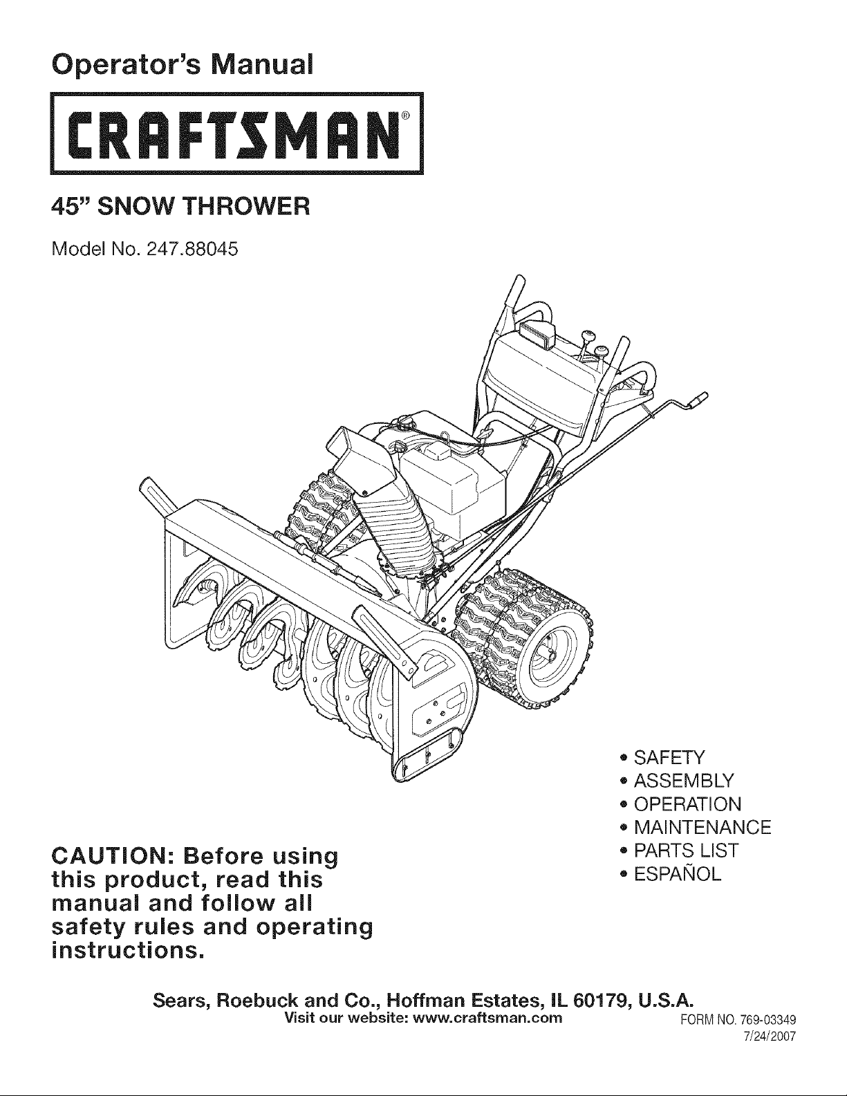
45" SNOW THROWER
Model No. 247.88045
CAUTION: Before using
this product, read this
manual and follow all
safety rules and operating
instructions.
Sears, Roebuck and Co., Hoffman Estates, IL 60179, U.S.A.
Visit our website: www, craftsrnan.corn FORMNO.769-03349
• SAFETY
ASSEMBLY
OPERATION
MAINTENANCE
PARTS LIST
ESPANOL
7/24/2007
Page 2
WarrantyStatement..................................Page2
RepairProtectionAgreement...................Page3
SafeOperationPractices.........................Pages4-5
SafetyLabels............................................Page7
Assembly..................................................Pages8-11
Operation..................................................Pages12-15
ServiceandMaintenance.........................Pages16-23
Off-SeasonStorage..................................Page24
TroubleShooting......................................Page25
PartsList...................................................Page26-36
Espa_ol.....................................................Page40
ServiceNumbers......................................BackCover
Two-YearWarranty on CraftsmanSnowThrower
Thisequipmentiscoveredbyatwo-yearwarranty,providedthatitismaintained,lubricated,andtunedupaccordingtotheinstructionsinthe
operator'smanual.Duringthewarrantyyears,ifthisequipmentexperiencesanyfailureduetodefectsinmaterialorworkmanship,RETURNIT
TOYOURNEARESTSEARSPARTS&REPAIRCENTER,andSearswillrepairit,freeofcharge.In-homewarrantyserviceisavailable,butyou
willhavetopayatripcharge.
Thiswarrantydoesnotcover:
• Expendableitemswhichbecomewornduringnormaluse,suchasskidshoes,shaveplateandsparkplugs.
• Repairsnecessarybecauseof operatornegligence,includingbutnotlimitedto,electricalandmechanicaldamagecausedbyimproper
storage,bentcrankshafts,failuretousethepropergradeandamountofengineoil,orfailuretomaintaintheequipmentaccordingto the
instructionscontainedintheoperator'smanual.
• Engine(fuelsystem)cleaningorrepairscausedbyfueldeterminedtobecontaminatedor oxidized(stale). Ingeneral,fuelshouldbeused
within30 daysof itspurchasedate.
• Equipmentifusedforcommercialorrentalpurposes.
Thiswarrantyappliesforonly90 daysif this productis everusedforcommercialorrentalpurposes.
This warrantyappliesonlywhilethisproductis usedintheUnitedStates.
This warrantygivesyouspecificlegalrights,andyoumayalsohaveotherrightswhichvaryfromstateto state.
Sears, Roebuck and Co., Hoffman Estates, IL 60179
EngineOil Type: SAE5W-30
EngineOil Capacity: 28 ounces
FuelCapacity: 4 Quarts
SparkPlug: Champion@RJ19LM
SparkPlugGap: .030"
ModelNumber.................................................................
Serial Number.................................................................
Dateof Purchase.............................................................
Recordthemodelnumber,serialnumber
anddateof purchaseabove
©SearsBrands,LLC
Page 3
Congratulationson makingasmartpurchase.YournewCraftsman®
productisdesignedandmanufacturedfor yearsofdependableopera-
tion.Butlikeall products,it mayrequirerepairfromtimetotime.That's
whenhavinga RepairProtectionAgreementcansaveyou moneyand
aggravation.
Here'swhat'sincludedintheAgreement:
,, Expertserviceby our 12,000professionalrepairspecialists
,, Unlimitedserviceandnochargefor partsandlaboronallcovered
repairs
,, Productreplacementif yourcoveredproductcan'tbe fixed
,, Discountof 10%fromregularpriceof serviceandservice-related
partsnotcoveredbytheagreement;also,10%offregularpriceof
preventivemaintenancecheck
,, Fasthelpbyphone- phonesupportfromaSearstechnicianon
productsrequiringin-homerepair,plusconvenientrepair
scheduling
Purchasea RepairProtectionAgreementnowandprotectyourself
fromunexpectedhassleandexpense.
Onceyou purchasetheAgreement,a simplephonecallisall thatit
takesfor you toscheduleservice.Youcan call anytimedayornight,or
schedulea serviceappointmentonline.
Searshasover12,000professionalrepairspecialists,whohave
accesstoover4.5millionqualitypartsandaccessories.That'sthe
kindof professionalismyoucan counton to helpprolongthelifeof
yournewpurchaseforyearstocome.PurchaseyourRepairProtection
Agreementtoday!
Somelimitationsand exclusionsapply. For pricesand additional
informationcall 1-800-827-6655.
SearsInstallation Service
ForSearsprofessionalinstallationof homeappliances,garagedoor
openers,waterheaters,andothermajorhomeitems,in the U.S.A.call
1-800-4-MY-HOME®
Page 4
which,ifnotfollowed,couldendangerthepersonal
__L Thissymbolpointsoutimportantsafetyinstructions
safetyand/orpropertyofyourselfandothers.Read
andfollowallinstructionsinthismanualbefore
attemptingtooperatethismachine.Failuretocomplywiththese
instructionsmayresultinpersonalinjury.Whenyouseethissymbol,
HEEDITSWARNING!
Thismachinewasbuilttobeoperatedaccordingtotherulesfor
safeoperationinthismanual.Aswithanytypeofpowerequipment,
carelessnessorerroronthepartoftheoperatorcanresultinserious
injury.Thismachineiscapableofamputatinghandsandfeetand
throwingobjects.Failuretoobservethefollowingsafetyinstructions
couldresultinseriousinjuryordeath.
YourResponsibility:Restricttheuseofthispowermachineto
personswhoread,understand,andfollowthewarningsandinstruc-
tionsinthismanualandonthemachine.
TRAINING
,, Read,understand,andfollowallinstructionsonthemachineandin
the manual(s)beforeattemptingtoassembleandoperate.Keepthis
manualina safeplacefor future andregularreferenceandfor ordering
replacementparts.
,, Be familiarwithallcontrolsandtheirproperoperation.Knowhowto stop
the machineanddisengagethemquickly.
,, Neverallowchildrenunder14yearsoldto operatethis machine.Chil-
dren14yearsoldandovershouldreadandunderstandtheoperation
instructionsandsafetyrulesinthis manualand shouldbetrainedand
supervisedbya parent.
,, Neverallowadultsto operatethismachinewithout properinstruction.
,, Thrownobjectscancauseseriouspersonalinjury.Planyoursnow-
throwingpatterntoavoiddischargeof materialtowardroads,bystanders
andthe like.
,, Keepbystanders,helpers,petsandchildrenat least 75feet fromthe
machinewhileit is inoperation.Stop machineif anyoneentersthearea.
,, Exercisecautiontoavoidslippingorfalling,especiallywhenoperatingin
reverse.
Engine Exhaust, some of its constituents, and certain vehicle
components contain or emit chemicals known to Stateof California to
1cause cancer and birth defects or other reproductive harm.
PREPARATION
Thoroughlyinspecttheareawheretheequipmentisto beused.Removeall
doormats,newspapers,sleds,boards,wiresandotherforeignobjects,which
couldbetrippedoverorthrownbythe auger/impeller.
,, Alwayswearsafetyglassesoreyeshieldsduringoperationandwhile
performinganadjustmentor repairto protectyoureyes.Thrownobjects
whichricochetcancauseserious injurytothe eyes.
,, Donotoperatewithoutwearingadequatewinteroutergarments.Donot
wearjewelry,longscarvesor otherlooseclothing,whichcouldbecome
entangledinmovingparts.Wearfootwearwhichwill improvefootingon
slipperysurfaces.
,, Usea groundedthree-wireextensioncordand receptacleforall units
with electricstartengines.
,, Adjustcollectorhousingheighttoclear gravelor crushedrocksurfaces.
,, Disengageallcontrolleversbeforestartingtheengine.
,, Neverattemptto makeanyadjustmentswhileengineis running,except
wherespecificallyrecommendedintheoperator'smanual.
,, Letengineandmachineadjustto outdoortemperaturebeforestartingto
clearsnow.
Safe Handling of Gasoline
Toavoidpersonalinjuryorpropertydamageuseextremecarein handling
gasoline.Gasolineisextremelyflammableandthevaporsareexplosive.
Seriouspersonalinjurycanoccurwhengasolineis spilledonyourselforyour
clothes,whichcan ignite.Washyourskinandchangeclothesimmediately.
,, Useonlyan approvedgasolinecontainer.
,, Extinguishall cigarettes,cigars,pipesandothersourcesofignition.
,, Neverfuelmachineindoors.
,, Neverremovegascaporaddfuel whilethe engineishot or running.
,, Allowenginetocoolatleasttwominutesbeforerefueling.
,, Neveroverfillfuel tank.Filltankto nomorethan Y2inch belowbottomof
fillerneckto providespacefor fuelexpansion.
,, Replacegasolinecapandtightensecurely.
,, Ifgasolineisspilled,wipeit offthe engineandequipment.Move
machineto anotherarea.Wait5 minutesbeforestartingtheengine.
,, Neverstorethemachineorfuelcontainerinsidewherethere isan open
flame,sparkor pilotlight(e.g.furnace,waterheater,spaceheater,
clothesdryeretc.).
,, Allowmachineto coolatleast5minutesbeforestoring.
4
Page 5
OPERATION
. Do notputhandsorfeet nearrotatingparts,intheauger/impeller
housingor chuteassembly.Contactwiththerotatingpartscanamputate
handsand feet.
,, The auger/impellercontrolleverisasafetydevice.Neverbypassits
operation.Doingso makesthe machineunsafeandmaycause personal
injury.
,, The controlleversmustoperateeasilyin bothdirectionsandautomati-
callyreturnto thedisengagedpositionwhenreleased.
,, Neveroperatewitha missingor damagedchuteassembly.Keepall
safetydevicesinplaceand working.
,, Neverrunan engineindoorsorin apoorlyventilatedarea.Engine
exhaustcontainscarbonmonoxide,anodorlessanddeadlygas.
,, Do notoperatemachinewhileunderthe influenceofalcoholordrugs.
,, Mufflerandenginebecomehotand cancauseaburn.Donottouch.
. Exerciseextremecautionwhenoperatingonorcrossinggravel surfaces.
Stayalertfor hiddenhazardsortraffic.
. Exercisecautionwhenchangingdirectionand whileoperatingon slopes.
. Planyoursnow-throwingpatterntoavoiddischargetowardswindows,
walls,carsetc.Thus,avoidingpossiblepropertydamageorpersonal
injurycausedbya ricochet.
. Neverdirectdischargeatchildren,bystandersand petsorallowanyone
infrontofthe machine.
. Do notoverloadmachinecapacitybyattemptingto clearsnowattoofast
ofa rate.
. Neveroperatethis machinewithoutgoodvisibilityor light.Alwaysbe
sureof your footingandkeepa firm holdonthe handles.Walk, never
run.
. Disengagepowertothe auger/impellerwhentransportingor notinuse.
,, Neveroperatemachineat hightransportspeedsonslipperysurfaces.
Lookdownand behindand usecarewhenbackingup.
,, If the machineshouldstarttovibrateabnormally,stoptheengine,
disconnectthesparkplugwireandgrounditagainsttheengine.Inspect
thoroughlyfordamage.Repairanydamagebeforestartingandoperat-
ing.
. Disengageallcontrolleversandstop enginebeforeyouleavethe
operatingposition(behindthe handles).Waituntilthe auger/impeller
comesto a completestopbeforeuncloggingthe chute assembly,making
anyadjustments,orinspections.
,, Neverputyourhandinthe dischargeor collectoropenings.Always
usetheclean-outtoolprovidedto unclogthedischargeopening.Do
not unclogchuteassemblywhileengineisrunning.Shutoffengine
andremainbehindhandlesuntilallmovingpartshavestoppedbefore
unclogging.
,, Useonlyattachmentsandaccessoriesapprovedbythemanufacturer
(e.g.wheelweights,tirechains,cabs etc.).
,, If situationsoccurwhich arenotcoveredinthismanual,usecareand
goodjudgment.ContactyourSearsServiceCenterforassistance.
MAINTENANCE & STORAGE
. Nevertamperwithsafetydevices.Checktheir properoperation
regularly.Referto the maintenanceandadjustmentsectionsofthis
manual.
,, Beforecleaning,repairing,or inspectingmachinedisengageallcontrol
leversand stoptheengine.Waituntiltheauger/impellercometoa
completestop.Disconnectthe sparkplug wireand groundagainstthe
enginetopreventunintendedstarting.
. Checkboltsandscrewsfor propertightnessatfrequentintervalsto keep
the machinein safeworkingcondition.Also,visuallyinspectmachinefor
anydamage.
. Donotchangetheenginegovernorsettingor over-speedthe engine.
Thegovernorcontrolsthe maximumsafeoperatingspeedoftheengine.
. Snowthrowershaveplatesandskidshoesare subjectto wearand
damage.Foryoursafetyprotection,frequentlycheckallcomponents
andreplacewith originalequipmentmanufacturer's(OEM) partsonly.
"Useof partswhichdonotmeetthe originalequipmentspecifications
may leadto improperperformanceandcompromisesafety!"
. Checkcontrolsperiodicallytoverifytheyengageanddisengage
properlyandadjust,ifnecessary.Referto theadjustmentsectionin this
operator'smanualfor instructions.
. Maintainorreplacesafetyandinstructionlabels,as necessary.
. Observeproperdisposallawsandregulationsforgas, oil,etc.to protect
the environment.
. Priortostoring,runmachineafewminutesto clearsnowfrom machine
andpreventfreezeup of auger/impeller.
. Neverstorethe machineorfuelcontainerinsidewherethere isanopen
flame,sparkor pilotlightsuch asawaterheater,furnace,clothes dryer
etc.
,, Alwaysreferto the operator'smanualfor properinstructionson
off-seasonstorage.
Do not modify engine
Toavoidseriousinjuryor death,do notmodifyenginein anyway.Tampering
withthegovernorsettingcanleadto a runawayengineandcauseitto operate
at unsafespeeds.Nevertamperwithfactorysettingofenginegovernor.
Notice Regarding Emissions
Engineswhichare certifiedtocomplywithCaliforniaandfederalEPAemission
regulationsforSORE(SmallOffRoadEquipment)are certifiedto operateon
regularunleadedgasoline,and mayincludethefollowingemissioncontrolsys-
tems:EngineModification(EM)andThreeWayCatalyst(TWO)if soequipped.
Page 6

Thispage left intentionallyblank.
6
Page 7
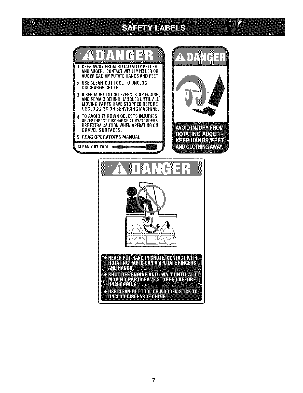
1.KEEPAWAYFROMROTATINGiMPELLER
ANDAUGER.CONTACTWiTHiMPELLEROR
AUGERCANAMPUTATEHANDSANDFEET.
2. USECLEAN-OUTTOOLTOUNCLOG
DISCHARGECHUTE.
3. DISENGAGECLUTCHLEVERS,STOPENGINE,
ANDREMAINBEHINDHANDLESUNTILALL
MOVINGPARTSHAVESTOPPEDBEFORE
UNCLOGGINGDRSERViCiNGMACHINE.
4. TOAVOIDTHROWNOBJECTSiNJURiES,
NEVERDIRECTDISCHARGEATBYSTANDERS.
USEEXTRACAUTIONWHENOPERATINGON
GRAVELSURFACES.
5. READOPERATOR'SMANUAL.
CLEAN-OUT TOOL
7
Page 8
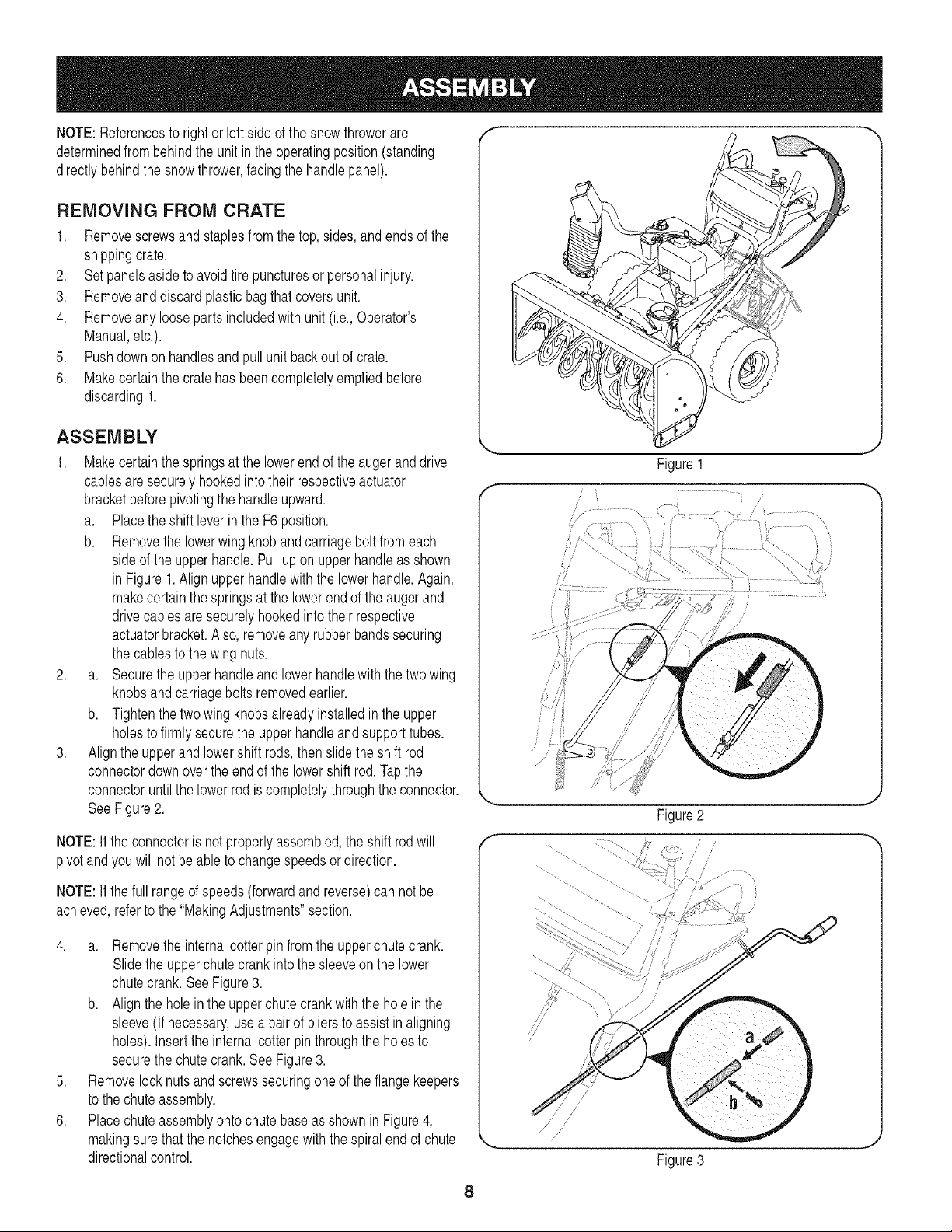
NOTE:Referencesto rightor leftsideof thesnowthrowerare
determinedfrombehindtheunitintheoperatingposition(standing
directlybehindthesnowthrower,facingthehandlepanel).
REMOVING FROM CRATE
1. Removescrewsandstaplesfromthetop,sides,andendsofthe
shippingcrate.
2. Setpanelsasidetoavoidtirepuncturesorpersonalinjury.
3. Removeanddiscardplasticbagthatcoversunit.
4. Removeanyloosepartsincludedwithunit(i.e.,Operator's
Manual,etc.).
5. Pushdownonhandlesand pullunitbackout of crate.
6. Makecertainthecratehasbeencompletelyemptiedbefore
discardingit.
ASSEMBLY
1. Makecertainthespringsat the lowerendof the augeranddrive
cablesaresecurelyhookedintotheirrespectiveactuator
bracketbeforepivotingthehandleupward.
a. Placetheshift leverintheF6 position.
b. Removethelowerwingknobandcarriageboltfromeach
sideof theupperhandle.Pullupon upperhandleasshown
in Figure1.Alignupperhandlewiththelowerhandle.Again,
makecertainthespringsatthe lowerendoftheaugerand
drivecablesaresecurelyhookedintotheir respective
actuatorbracket.Also,removeanyrubberbandssecuring
thecablestothewingnuts.
2. a. Securetheupperhandleandlowerhandlewiththetwowing
knobsandcarriageboltsremovedearlier.
b. Tightenthetwowingknobsalreadyinstalledintheupper
holesto firmlysecuretheupperhandleandsupporttubes.
3. Alignthe upperand lowershiftrods,thenslidetheshiftrod
connectordownoverthe endofthe lowershiftrod.Tapthe
connectoruntilthe lowerrodis completelythroughtheconnector.
SeeFigure2.
NOTE:If theconnectoris notproperlyassembled,theshiftrodwill
pivotand youwillnotbe abletochangespeedsordirection.
NOTE:If thefullrangeof speeds(forwardandreverse)can notbe
achieved,refertothe"MakingAdjustments"section.
Figure1
/
/
//
i/ ..........
/'-_F .......
Figure2
f
/
4. a. Removetheinternalcotterpinfromtheupperchutecrank.
Slidetheupperchutecrankintothesleeveon thelower
chutecrank.SeeFigure3.
b. Aligntheholein theupperchutecrankwiththeholein the
sleeve(If necessary,usea pairofplierstoassistin aligning
holes).Insertthe internalcotterpinthroughtheholesto
securethechutecrank.SeeFigure3.
5. Removelocknutsandscrewssecuringoneoftheflangekeepers
tothechuteassembly.
6. Placechuteassemblyontochutebaseasshownin Figure4,
makingsurethat thenotchesengagewiththespiralend ofchute
directionalcontrol.
/
/
Figure3
8
Page 9
7. Secureflangekeeperremovedearlierwithlocknutsandscrews.
Tightendownnutssecuringtheothertwoflangekeepers.See
Figure5.
8. Ifnotalreadydone,slipthecablesthatrunfromthehandle
paneltothedischargechuteintothe cableguidelocatedontop
of theengine.SeeFigure4.
9. Ifnotalreadydone,wrapthewireoftheheadlampwireharness
downtherighthandleuntilthewirecanbepluggedintothe
enginealternatorwireconnectordownonthe engine.
10. Normallythecableties holdingthesteeringcablesagainstthe
handlearelooselyinstalledoneachsideofthelowerhandleat
thefactory.Pullthecabletiestighttosecure.Cuttheexcess
fromtheendsofcable ties.
Theextensioncordisfastenedwitha cabletietotherearof theauger
housingforshippingpurposes.Cutthe cabletie andremoveitbefore
operatingthesnowthrower.
1/
ii
..............
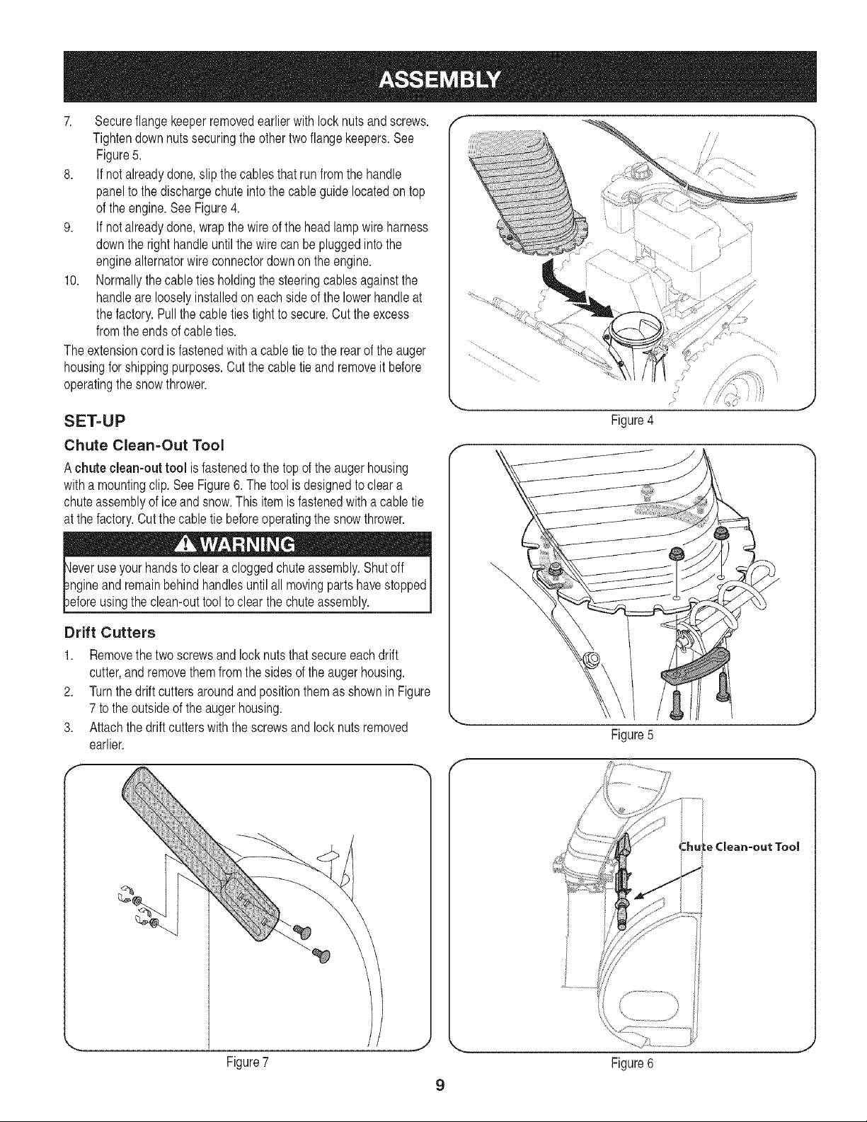
SET-UP
Chute Clean-Out Tool
Achute clean-out tool isfastenedtothetop oftheaugerhousing
withamountingclip.SeeFigure6.The toolisdesignedtocleara
chuteassemblyoficeandsnow.Thisitemisfastenedwitha cabletie
atthefactory.Cutthecabletiebeforeoperatingthesnowthrower.
Drift Cutters
1. Removethetwoscrewsandlocknutsthatsecureeachdrift
cutter,andremovethemfromthesidesoftheaugerhousing.
2. Turnthedriftcuttersaroundandpositionthemasshownin Figure
7 to theoutsideoftheaugerhousing.
3. Attachthe driftcutterswiththe screwsandlocknutsremoved
earlier.
Figure4
\
Figure5
Figure7
:hule Clean-out Tool
Figure6
9
Page 10
Tire Pressure f
Beforeoperating,checktirepressure.Refertothetiresidewallfor
exacttiremanufacturer'srecommendedor maximumpsi.
NOTE:If thetirepressureis notequalinbothtires,theunitmaynot
travelinastraightpathandtheshaveplatemaywearunevenly.
ADJUSTMENTS
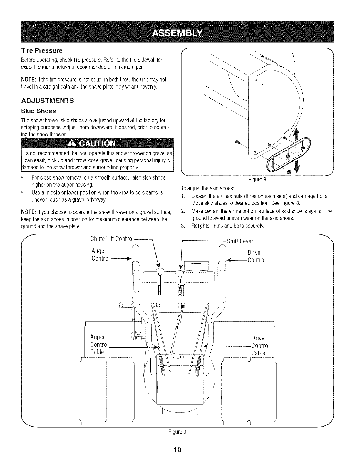
Skid Shoes
Thesnowthrowerskidshoesareadjustedupwardatthefactoryfor
shippingpurposes.Adjustthemdownward,if desired,priorto operat-
ingthesnowthrower.
isnotrecommendedthat this thrower
It youoperate snow on gravelas
it.caneasilypickupandthrowloosegravel,causingpersonalinjuryor i
_damageto the snowthrowerandsurroundingproperty, j
,, Forclosesnowremovalon a smoothsurface,raiseskidshoes
higherontheaugerhousing.
,, Usea middleorlowerpositionwhentheareatobeclearedis
uneven,suchasagraveldriveway
NOTE:Ifyouchoosetooperatethesnowthroweronagravelsurface,
keeptheskidshoesin positionfor maximumclearancebetweenthe
groundand theshaveplate.
Figure8
Toadjusttheskidshoes:
1. Loosenthesix hexnuts(threeon eachside)andcarriagebolts.
Moveskid shoestodesiredposition.SeeFigure8.
2. Makecertaintheentirebottomsurfaceof skidshoeisagainstthe
groundtoavoidunevenwearon theskidshoes.
3. Retightennutsandboltssecurely.
Chute Tilt Controi_
Auger
Control----4_ .
Auger !
Control
Cable
-Shift Lever
i Drive
_e--_ Contro
Drive
Control
Cable
7
Figure9
10
J
Page 11
Testing Auger Drive Control "*
Priortooperatingyoursnowthrower,carefullyreadandfollowall
instructionsbelow.Performalladjustmentsto verifyyoursnow
throwerisoperatingsafelyandproperly.
Whentheaugercontrolisreleasedand inthedisengaged"up"posi-
tion,thecableshouldhaveverylittleslack,butshouldNOTbetight.
1. Ina well-ventilatedarea,startthesnowthrowerengineas
instructedin the O_erationsection.Makesurethethrottleissetin
thefastposition.G_p
2. Whilestandingintheoperator'sposition(behindthesnow
thrower),engagethe augercontrolandallowthe augerto remain
engagedforapproximatelytensecondsbeforereleasingthe
augercontrol.Repeatthisseveraltimes.
3. Withtheenginerunninginthefastposition '_ andthe
augercontrolinthe disengaged"up"position,walktothefront
ofthemachine.Confirmthattheaugerhascompletelystopped
rotatingandshowsnosignsof motion.
4. If theaugershowsanysignsof rotating,immediatelyreturntothe
operator'spositionandshutoffthe engine.Waitforallmoving
partstostopbeforereadjustingtheaugercontrolcable.
Testing Drive Control & Shift Lever
RefertoFigure9 for locationofcontrols.
1. Movetheshiftleverintosixth(6)position.
2. Withthewheeldrivecontrolreleased,pushthesnowthrower
forward,thenpullit back.The machineshouldmovefreely.
3. Engagethedrivecontrolandattempttomovethemachineboth
forwardandback,resistanceshouldbefelt.
4. Movetheshiftleverintothefastreverse(R2)positionandrepeat
theprevioustwosteps.
If youexperiencedresistancerollingtheunit,eitherwhenrepositioning
theshiftleverfrom6toR2orwhenattemptingto movethemachine
withthedrivecontrolreleased,adjustthedrive controlimmediately.
SeeAdjustingDriveandAugerControls.
4
Figure10
f
Adjusting Drive and Auger Controls
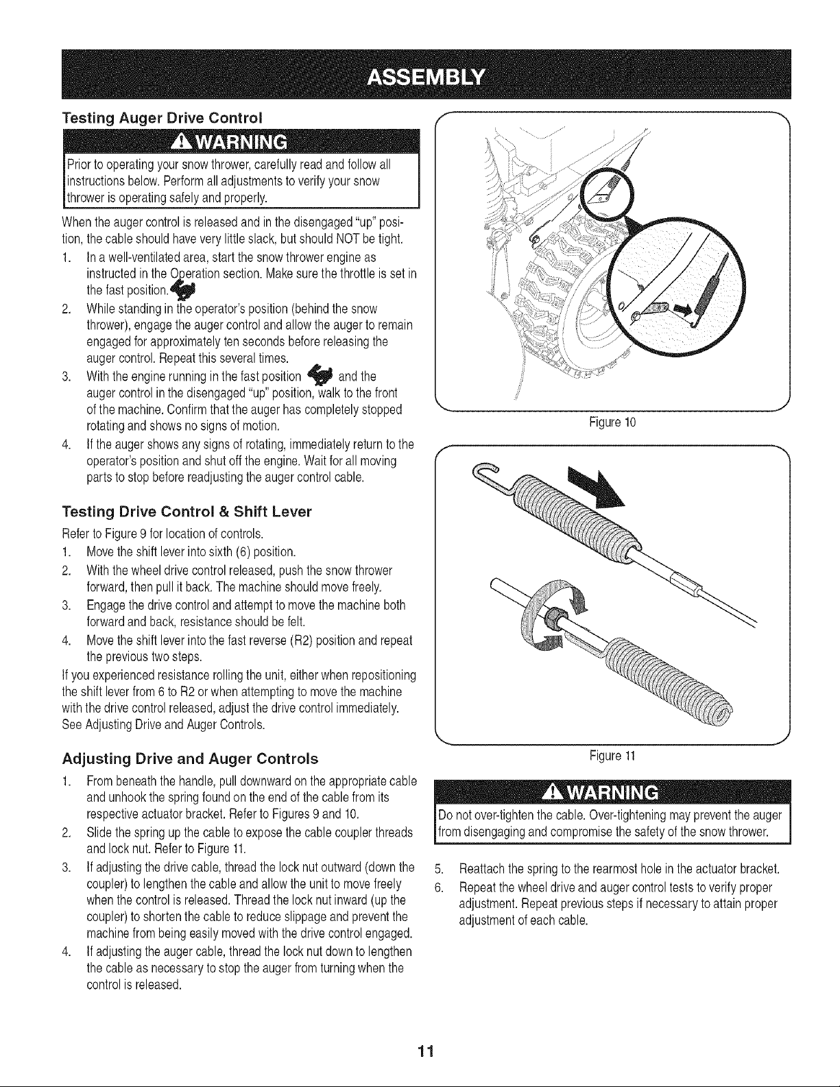
1. Frombeneaththehandle,pulldownwardon theappropriatecable
andunhookthespringfoundontheendofthecablefromits
respectiveactuatorbracket.RefertoFigures9and10.
2. Slidethespringupthecabletoexposethecablecouplerthreads
andlocknut.Referto Figure11.
3. If adjustingthedrivecable,threadthelocknut outward(downthe
coupler)tolengthenthecableandallowtheunittomovefreely
whenthe controlis released.Threadthe locknutinward(upthe
coupler)toshortenthecableto reduceslippageandpreventthe
machinefrombeingeasilymovedwiththedrivecontrolengaged.
4. If adjustingtheaugercable,threadthelocknutdowntolengthen
thecableas necessarytostoptheaugerfromturningwhenthe
controlis released.
Figure11
Donotover-tightenthecable.Over-tighteningmaypreventtheauger I
Ifromdsengagngandcompromsethesafetyof the snowthrower. J
5,
Reattachthespringto therearmostholeintheactuatorbracket.
6.
Repeatthewheeldriveandaugercontrolteststo verifyproper
adjustment.Repeatpreviousstepsifnecessarytoattainproper
adjustmentofeachcable.
11
Page 12
f
DriveControl
Drift
Cutters
/
Assembl
Augers
OilFill
Chute
/
GasCa
Headlk
Lever
Two-Way
Chute ControP
Control
I Steering
ol
•ChuteDirectional
Control
Tool
Skid Shoe
Figure11
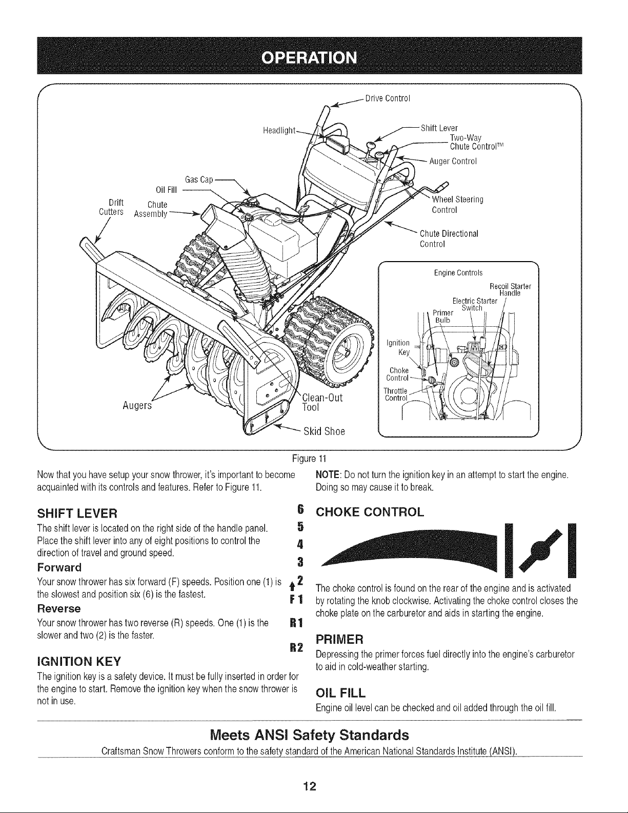
Nowthatyouhavesetupyoursnowthrower,it'simportanttobecome NOTE:Donotturntheignitionkeyinan attempttostartthe engine.
acquaintedwith itscontrolsandfeatures.RefertoFigure11. Doingso maycauseit tobreak.
SHIFT LEVER
Theshift leverislocatedon the rightsideofthehandlepanel.
Placetheshift leverintoanyofeightpositionsto controlthe
directionof travelandgroundspeed.
Forward
Yoursnowthrowerhassix forward(F)speeds.Positionone(1)is t 2 Thechokecontrolis foundonthe rearof theengineandisactivated
theslowestand positionsix (6)is thefastest.
Reverse
Yoursnowthrowerhastwo reverse(R)speeds.One(1)is the
slowerandtwo(2) is thefaster.
Ii CHOKE CONTROL
I11
FI
byrotatingthe knobclockwise.Activatingthechokecontrolclosesthe
chokeplateonthecarburetorandaidsinstartingtheengine.
R1
PRIMER
R2
IGNITION KEY
Theignitionkeyisa safetydevice.It mustbefullyinsertedinorderfor
theenginetostart,Removetheignitionkeywhenthesnowthroweris
notinuse.
Depressingthe primerforcesfueldirectlyintotheengine'scarburetor
toaid incold-weatherstarting.
OIL FILL
Engineoil levelcanbecheckedandoiladdedthroughtheoil fill.
Meets ANSI Safety Standards
CraftsmanSnowThrowersconformto thesafetystandardoftheAmericanNationalStandardsInstitute(ANSI).
12
Page 13
THROTTLE CONTROL
Thethrottlecontrolis locatedontherearoftheengine.
It regulatesthespeedofthe engineandwillshutoff the
enginewhenmovedintotheSTOPposition.
SKID SHOES
Positiontheskidshoesbasedon surfaceconditions.Adjust
upwardforhard-packedsnow.Adjustdownwardwhen
operatingongravelorcrushedrocksurfaces.
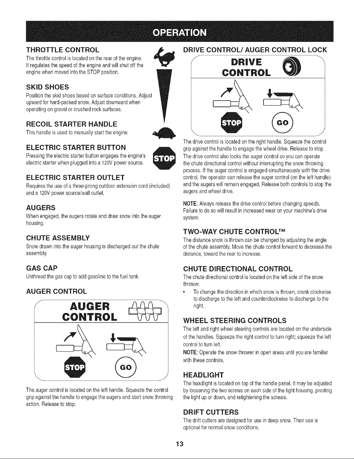
DRIVE CONTROL/AUGER CONTROL LOCK
f
DRIVE
CONTROL
RECOIL STARTER HANDLE
This handleisusedto manuallystarttheengine.
ELECTRIC STARTER BUTTON
Pressingtheelectricstarterbuttonengagestheengine's
electricstarterwhenpluggedintoa 120Vpowersource.
ELECTRIC STARTER OUTLET
Requirestheuseofathree-prongoutdoorextensioncord(included)
anda120Vpowersource/walloutlet.
AUGERS
Whenengaged,the augersrotateanddrawsnowintotheauger
housing.
CHUTE ASSEMBLY
Snowdrawnintotheaugerhousingisdischargedoutthechute
assembly.
GAS CAP
Unthreadthegascap toaddgasolineto thefueltank.
AUGER CONTROL
S
@
Thedrivecontrolis locatedon therighthandle.Squeezethecontrol
gripagainstthehandletoengagethewheeldrive.Releaseto stop.
Thedrivecontrolalso locksthe augercontrolso youcanoperate
thechutedirectionalcontrolwithoutinterruptingthesnowthrowing
process.If the augercontrolisengagedsimultaneouslywiththedrive
control,the operatorcanreleasetheaugercontrol(onthelefthandle)
andtheaugerswillremainengaged.Releaseboth controlstostopthe
augersandwheeldrive.
NOTE:Alwaysreleasethedrivecontrolbeforechangingspeeds.
Failuretodoso willresultinincreasedwearonyourmachine'sdrive
system.
TWO=WAY CHUTE CONTROL TM
Thedistancesnowis throwncanbechangedbyadjustingtheangle
of thechuteassembly.Movethechutecontrolforwardtodecreasethe
distance,towardtherearto increase.
CHUTE DIRECTIONAL CONTROL
Thechutedirectionalcontrolislocatedontheleftsideofthesnow
thrower.
,, Tochangethedirectioninwhichsnowis thrown,crankclockwise
todischargetotheleftandcounterclockwisetodischargetothe
right.
Theaugercontrolislocatedonthe lefthandle.Squeezethe control
gripagainstthehandletoengagetheaugersandstart snowthrowing
action.Releasetostop.
WHEEL STEERING CONTROLS
Theleftandrightwheelsteeringcontrolsarelocatedontheunderside
of thehandles.Squeezetherightcontrolto turnright;squeezetheleft
controlto turnleft.
NOTE:Operatethesnowthrowerinopenareasuntilyouarefamiliar
withthesecontrols.
HEADLIGHT
Theheadlightislocatedontopofthehandlepanel.It maybeadjusted
bylooseningthe twoscrewsoneachsideofthelighthousing,pivoting
thelightupor down,andretighteningthescrews.
DRIFT CUTTERS
Thedriftcuttersaredesignedforusein deepsnow.Theiruseis
optionalfor normalsnowconditions.
13
Page 14
CLEAN-OUT TOOL NOTE:Aplasticdustcapmaybefoundinsidethefuelfillopening.
Removeanddiscard,if present.
Neveruseyourhandstoclearacloggedchuteassembly.Shut
off engineand remainbehindhandlesuntilallmovingpartshave
stoppedbeforeunclogging.
Thechuteclean-outtoolis convenientlyfastenedto the rearofthe
augerhousingwitha mountingclip. Shouldsnowandicebecome
lodgedin the chuteassemblyduringoperation,proceedasfollowsto
safelycleanthechuteassemblyandchuteopening:
1. ReleaseboththeAugerControlandthe DriveControl.
2. Stopthe enginebyremovingtheignitionkey.
3. Removetheclean-outtoolfromtheclipwhichsecuresittothe
rearoftheaugerhousing.
4. Usetheshovel-shapedendof theclean-outtoolto dislodgeand
scoopanysnowandicewhichhasformedin andnearthechute
assembly.
5. Refastentheclean-outtoolto the mountingclipon therearof
theaugerhousing,reinsertthe ignitionkeyandstartthesnow
thrower'sengine.
6. Whilestandingintheoperator'sposition(behindthesnow
thrower),engagethe augercontrolforafewsecondsto clearany
remainingsnowandicefromthechuteassembly.
BEFORE STARTING ENGINE
,, Alwaysfill thefueltankoutdoorsand usea funnelorspoutto
preventspilling.
,, Fillfuel tankwithclean,fresh,unleadedgasoline.
,, Neverfill thefueltankcompletely.Fillthe tanktowithin1/2"from
thetoptoprovidespaceforexpansionoffuel.
,, Makesureto wipeoff anyspilledfuelbeforestartingtheengine.
STARTING THE ENGINE
1. Attachsparkplugwiretosparkplug.Makecertainthe metal
loopon theendof the sparkplugwire(insidethe rubberboot)is
fastenedsecurelyoverthe metaltip onthesparkplug.
2. Makecertainboththeaugercontrolanddrivecontrolarein the
disengaged(released)position.
3. MovethrottlecontroluptoFAST_ position.Insertignitionkey
intoslot. Makesureitsnapsintoplace.Donotattemptto turn the
key.
NOTE:Theenginecannotstartwithoutthekeyis fullyinsertedintothe
ignitionswitch.
Electric Starter
Determinethatyourhome'swiringis a three-wiregroundedsystem.
Askalicensedelectricianifyouarenotcertain.
Read,understand,andfollowall instructionsandwarningsonthe
machineand inthis manualbeforeoperating.
Oil
Theunit wasshippedwithoilintheengine.Checkoil levelbeforeeach
operationtoensureadequateoilintheengine.Forfurtherinstructions,
referto the stepsonpage 17.
1. Removethedipstickfromtheoilfill.
2. Checkandmakesurethatthe levelofoil is upto theFULLmark
onthedipstick.
3. If theoil levelis notupto FULL,pourfreshmotoroil (5W-30,with
a minimumclassificationofSL/SJ)slowlythroughtheopening.
Replaceoil fill dipstickandcheckoil levelagain.
Gasoline
Useextremecarewhenhandlinggasoline.Gasolineisextremely
flammableandthevaporsareexplosive.Neverfuel themachine
indoorsorwhilethe engineishotor running.Extinguishcigarettes,
[c gars,ppesandothersourcesof gnt on.
,, Storegasolinein aclean,approvedcontainerandkeepthe capin
placeonthecontainer.
,, Makesurethatthecontainerfromwhichyoupourthegasolineis
cleanandfreefromrustor otherforeignparticles.
Theoptionalelectricstarteris equippedwithagroundedthree-wire
powercordandplug,andis designedtooperateon120voltAC
householdcurrent.It mustbeusedwith aproperlygroundedthree-
prongreceptacleatall timestoavoidthepossibilityof electricshock.
Followall instructionscarefullypriortooperatingtheelectricstarter.
Ifyouhavea groundedthree-prongreceptacle,proceedasfollows:
1. Plugtheextensioncordintothe outletlocatedontheengine's
surface.Plugtheotherend of extensioncordinto athree-prong
120-volt,grounded,ACoutletinawell-ventilatedarea.
2. RotatechokecontroltoFULL I,.#'1chokeposition(foracold
enginestart).
NOTE:If theengineis alreadywarm,placechokecontrolinthe OFF
positioninsteadofFULL IJl •
3. Pushtheprimertwoor threetimesforcoldenginestart, making
sureto coverventholeinthecenterofthe primerwhenpushing.
NOTE:DO NOTuse primerto restartawarmengineafterashort
shutdown.
4. Pushstarterbuttontostartengine.
NOTE:Donotholdthebuttondownforlongerthanseven(7)seconds
ata time.Doingso maydamageyourengine'selectricstarter.
14
Page 15
5. Oncetheenginestarts,releasestarterbutton.
6. Astheenginewarms,slowlyrotatechokecontrolto theOFF
position.Iftheenginefalters,quicklyrotatechokecontrolbackto
FULL 14D"Ithenslowlyintothe OFFpositionagain.
7. Whendisconnectingthe extensioncord,alwaysunplugtheend
atthethree-prongwalloutletbeforeunpluggingtheoppositeend
fromthesnowthrower.
Recoil Starter
1. Rotatechokecontrolto FULL IJl chokeposition(coldengine
start).
NOTE:Iftheengineisalreadywarm,placechokecontrolintheOFF
position
2. Pushthe primertwoorthreetimesforcoldenginestart,making
NOTE:DONOTuseprimertorestartawarmengineafterashort
shutdown.
NOTE:Additionalprimingmaybe necessaryifthe temperatureis
below15°Fahrenheit.
insteadofFULLIJ|.
sureto coverventholeinthecenterof the primerwhenpushing.
NOTE:Whenselectinga DriveSpeed,usethe slowerspeedsuntil
youarecomfortableandfamiliarwiththeoperationofthesnow
thrower.
2. Squeezethedrivecontrolagainstthehandlethe snowthrower
will move.Releaseitanddrivemotionwillstop.
NOTE:NEVERrepositiontheshiftlever(changespeedsordirection
of travel)withoutfirstreleasingthedrivecontrolandbringingthesnow
throwertoa completestop.Doingso will resultin prematurewearto
thesnowthrower'sdrivesystem.
TO ENGAGE AUGERS
1. Toengagethe augersandstartthrowingsnow,squeezethe
augercontrolagainstthelefthandle.Releasetostoptheaugers.
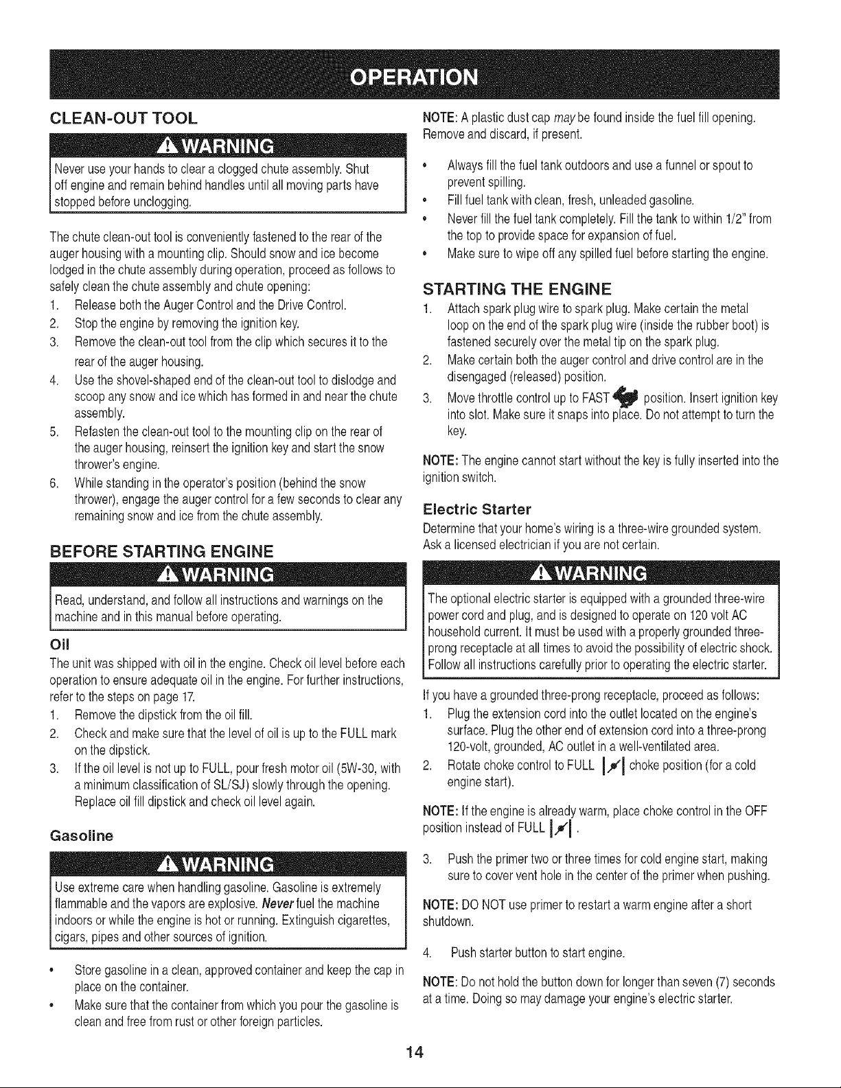
REPLACING SHEAR PiNS
Theaugersaresecuredto thespiralshaft withtwoshearpinsandcot-
terpins.if theaugershouldstrikea foreignobjectorice jam,thesnow
throwerisdesignedsothattheshearpinsmayshear.Iftheaugerswill
notturn,checkto seeifthepins havesheared.SeeFigure12.
3. Graspthe recoilstarterhandleandslowlypulltheropeout.Atthe
pointwhereitbecomesslightlyhardertopullthe rope,slowly
allowthe ropetorecoil.
4. Pullthestarterhandlewitha firm,rapidstroke.Donotrelease
thehandleandallowit to snapback.Keepafirmholdonthe
starterhandleandallowitto slowlyrecoil.
5. Astheenginewarms,slowlyrotatethechokecontroltotheOFF
position.Iftheenginefalters,quicklyrotatethechokecontrol
backtotheFULL I,_1 positionandthenslowlyintotheOFF
positionagain.
NOTE:Allowtheenginetowarmupfor afewminutesafterstarting.
Theenginewill notdevelopfullpoweruntilit reachesoperating
temperatures.
STOPPING THE ENGINE
Runenginefor a fewminutesbeforestoppingto helpdry off any
moistureonthe engine.
Movethrottlecontrolto STOP1.position.
2. Removethe ignitionkeyandstoreinasafeplace.
3. Wipeallsnowandmoisturefromtheareaaroundtheengineas
wellas the areainandaroundthedrivecontrolandaugercontrol.
Also,engageandreleasebothcontrolsseveraltimes.
NEVERreplacetheaugershearpinswith anythingotherthanOEM
PartNo.738-04124Areplacementshearpins.Anydamagetothe
augergearboxorothercomponentsasaresultof failingtodoso will
NOTbecoveredbyyoursnowthrower'swarranty.
Alwaysturnoffthe snowthrower'sengineand removethekeypriortc
replacingshearpins.
//
TO ENGAGE DRIVE
1. WiththethrottlecontrolintheFast_ position,moveshiftlever
intooneofthesix forward(F)positionsor tworeverse(R)
positions.Selecta speedappropriatefor thesnowconditionsand
a paceyou'recomfortablewith.
Figure12
15
Page 16
ENGINE MAINTENANCE
Beforelubricating,repairing,orinspecting,disengageallcontrols
land stopengine.Waituntilall movingpartshavecometoacomplete
[stop.
Checking Engine Oil
1. Besureengineisuprightandlevel
2. Unscrewoil fillcapfromoil fillertubeandwipedipstickclean.
3. Screwoil fillcapbackintooilfillertube.Tightensecurely.
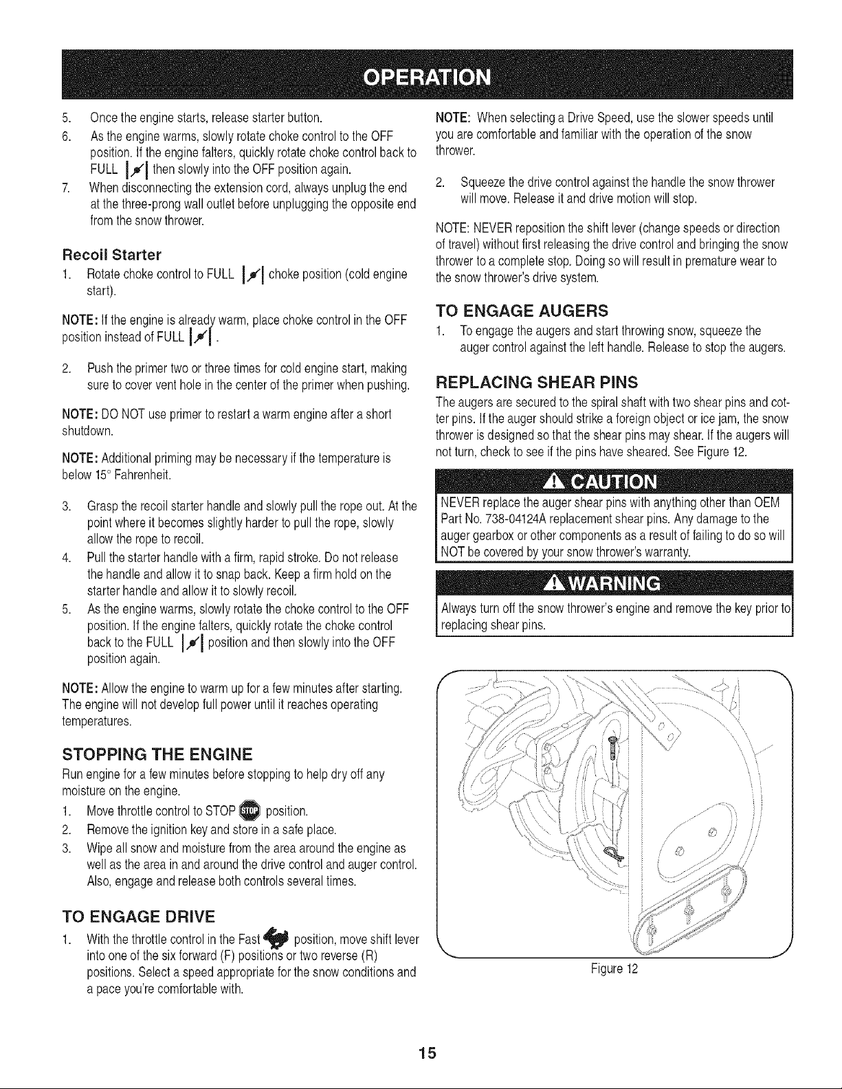
4. Unscrewandremoveoilfillcapfromoilfiller tube.Noteoil level.
If oil readingondipstickisbelow"ADD"mark,slowlyaddoilto
reach"FULL"level.SeeFigure13.
5. Screwoil fillcapbackintooilfillertube.Tightensecurely.
6. Wipeawayanyspilledoil.
f --,,
FULL
Maintain oil level
between FULLand ADD
ADD
Changing Engine Oil
Toavoidenginedamage,itisimportantto:
,, Checkoil levelbeforeeachuseandeveryfiveoperatinghours.
,, Changeoilafterfirsttwo (2)operatinghoursandevery25 operat-
inghoursthereafter.
,, Engineshouldstillbewarmbut nothot fromrecentuse.
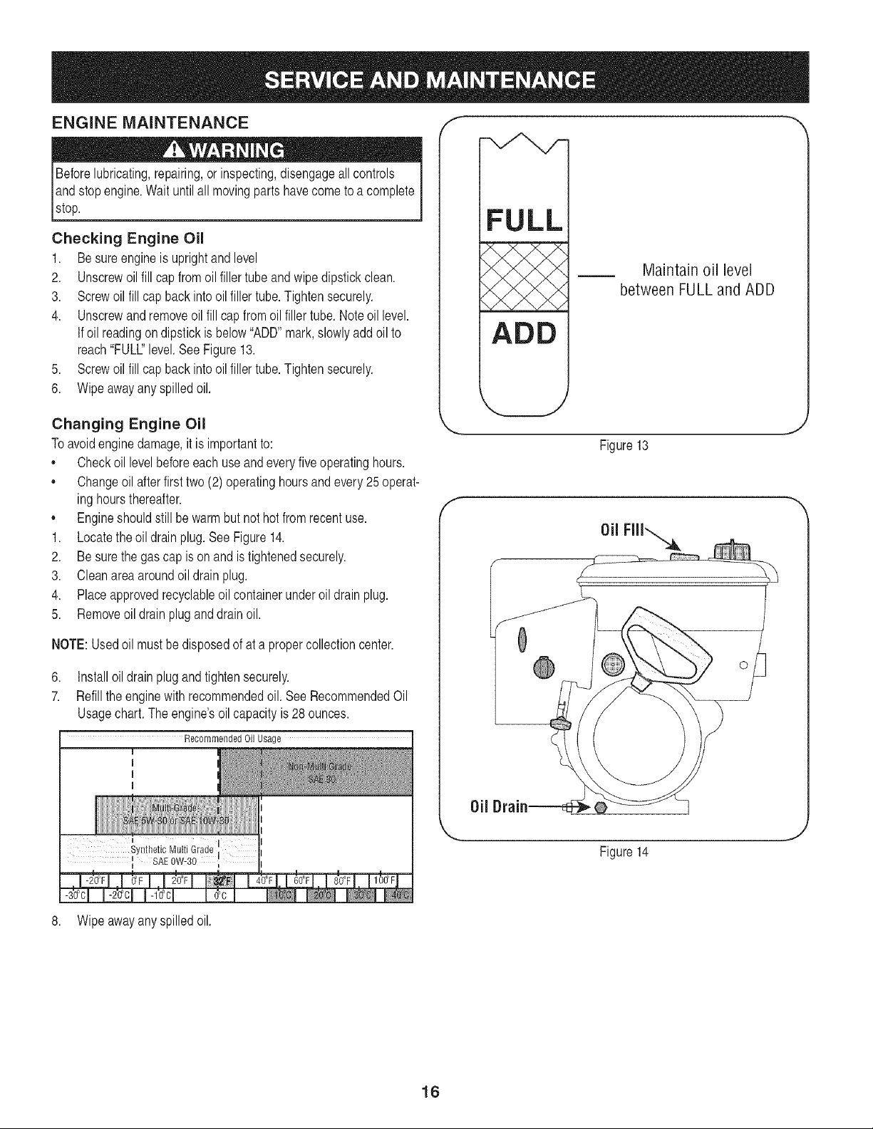
1. Locatetheoildrainplug.SeeFigure14.
2. Besurethegas cap isonandistightenedsecurely.
3. Cleanareaaroundoil drainplug.
4. Placeapprovedrecyclableoilcontainerunderoil drainplug.
5. Removeoildrainpluganddrainoil.
NOTE:Usedoil mustbedisposedof at a propercollectioncenter.
6. Installoildrain plugandtightensecurely.
7. Refilltheenginewithrecommendedoil.SeeRecommendedOil
Usagechart.The engine'soilcapacityis28 ounces.
Recommended Oil Usage
J
Figure13
f
SAE0W-30
I
8. Wipeawayanyspilledoil.
16
Page 17
Checking Spark Plug
Checksparkplugyearlyor every100operatinghours
1. Cleanareaaroundsparkplug.
2. Removeand inspectsparkplug.
3. Replacesparkplugif porcelainiscrackedorifelectrodesare
pitted,burnedorfouledwithdeposits
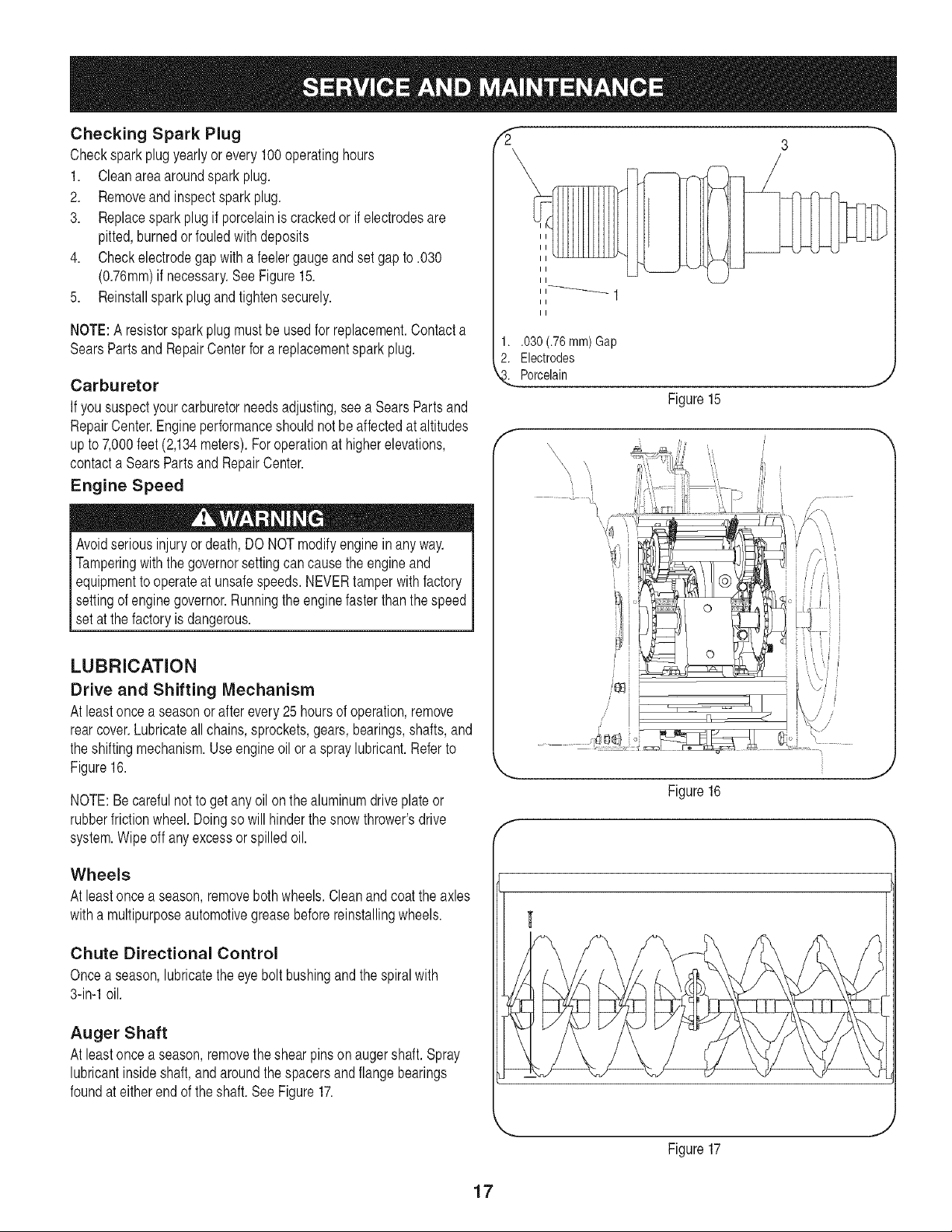
4. Checkelectrodegapwitha feelergaugeandset gapto.030
(0.76ram)ifnecessary.SeeFigure15.
5. Reinstallsparkplugandtightensecurely.
NOTE:A resistorsparkplugmustbeusedforreplacement.Contacta
SearsPartsand RepairCenterfora replacementsparkplug.
Carburetor
If yoususpectyourcarburetorneedsadjusting,seea SearsPartsand
RepairCenter.Engineperformanceshouldnotbe affectedataltitudes
upto7,000feet(2,134meters).Foroperationathigherelevations,
contacta SearsPartsandRepairCenter.
Engine Speed
Avoidseriousinjuryordeath,DONOTmodifyengineinanyway.
Tamperingwiththegovernorsettingcancausetheengineand
equipmenttooperateat unsafespeeds.NEVERtamperwithfactory
settingof enginegovernor.Runningtheenginefasterthanthespeed
set at thefactoryisdangerous.
LUBRICATION
Drive and Shifting Mechanism
Atleastoncea seasonorafterevery25hoursof operation,remove
rearcover.Lubricateall chains,sprockets,gears,bearings,shafts,and
theshiftingmechanism.Useengineoil or aspraylubricant.Referto
Figure16.
NOTE:Becarefulnotto getany oilonthealuminumdriveplateor
rubberfrictionwheel.Doingsowillhinderthesnowthrower'sdrive
system.Wipeoff anyexcessorspilledoil.
3
II
II
1..030 (.76ram)Gap
2. Electrodes
Porcelain
Figure15
f -'-,
,,, <¢_._ , , ,
,,,, _,,,
•••L.i,
,,,, _ ,,, _ [
,, ,_ [
f
I
Figure16
|¢
J
Wheels
Atleastoncea season,removebothwheels.Cleanandcoattheaxles
withamultipurposeautomotivegreasebeforereinstallingwheels.
Chute Directional Control
Oncea season,lubricatetheeyebolt bushingandthespiralwith
3-in-1oil.
Auger Shaft
Atleastoncea season,removethe shearpinsonaugershaft.Spray
lubricantinsideshaft,andaroundthespacersandflangebearings
foundat eitherendoftheshaft.SeeFigure17.
J
Figure17
17
Page 18
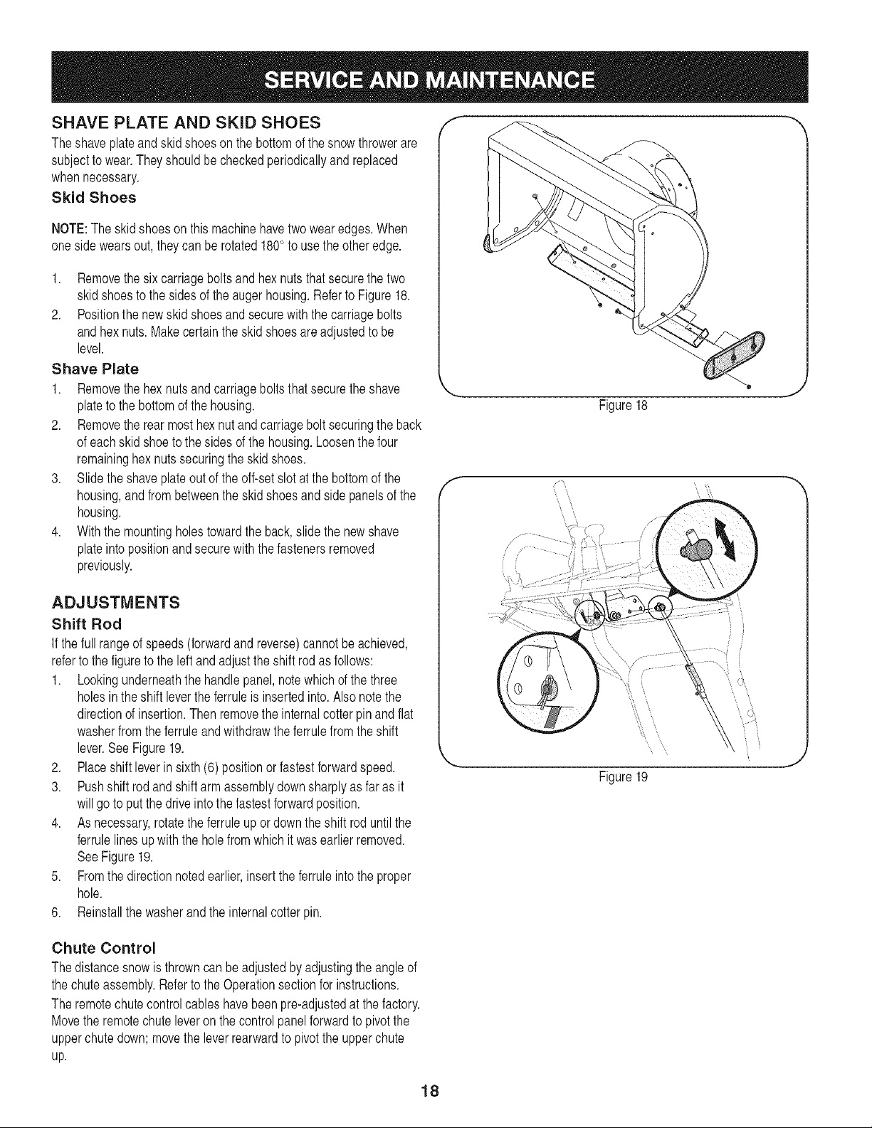
SHAVE PLATE AND SKID SHOES
Theshaveplateandskidshoesonthebottomofthesnowthrowerare
subjectto wear.Theyshouldbecheckedperiodicallyandreplaced
whennecessary.
Skid Shoes
NOTE:Theskidshoesonthismachinehavetwowearedges.When
onesidewearsout,theycan berotated180° to usetheotheredge.
1. Removethesixcarriageboltsandhexnutsthatsecurethe two
skidshoestothesidesoftheaugerhousing.RefertoFigure18.
2. Positionthenewskidshoesandsecurewiththecarriagebolts
andhexnuts.Makecertaintheskidshoesareadjustedtobe
level.
Shave Plate
1. Removethe hexnutsandcarriageboltsthatsecuretheshave
plateto the bottomof the housing.
2. Removethe rearmosthexnutandcarriageboltsecuringthe back
ofeachskidshoetothesidesofthehousing.Loosenthefour
remaininghexnutssecuringthe skidshoes.
3. Slidetheshaveplateoutoftheoff-setslot at thebottomofthe
housing,andfrombetweentheskidshoesandsidepanelsofthe
housing.
4. Withthemountingholestowardthe back,slidethenewshave
plateintopositionandsecurewith thefastenersremoved
previously.
f m
Figure18
ADJUSTMENTS
Shift Rod
If the fullrangeofspeeds(forwardandreverse)cannotbeachieved,
referto the figureto the leftandadjustthe shiftrodasfollows:
1. Lookingunderneaththehandlepanel,notewhichofthethree
holesintheshiftlevertheferruleisinsertedinto.Also notethe
directionofinsertion.Thenremovetheinternalcotterpin andflat
washerfromtheferruleandwithdrawtheferrulefromtheshift
lever.SeeFigure19.
2. Placeshift leverinsixth(6)positionor fastestforwardspeed.
3. Pushshift rodandshiftarmassemblydownsharplyas far asit
willgo toput thedriveintothefastestforwardposition.
4. Asnecessary,rotatetheferruleupor downtheshiftroduntilthe
ferrulelinesupwiththeholefromwhichitwasearlierremoved.
SeeFigure19.
5. Fromthedirectionnotedearlier,inserttheferruleintotheproper
hole.
6. Reinstallthewasherandtheinternalcotterpin.
Chute Control
Thedistancesnowisthrowncanbeadjustedbyadjustingtheangleof
thechuteassembly.Referto theOperationsectionfor instructions.
Theremotechutecontrolcableshavebeenpre-adjustedatthe factory.
Movetheremotechuteleveron thecontrolpanelforwardto pivotthe
upperchutedown;movethe leverrearwardto pivottheupperchute
up.
\\
\
\ \
18
Page 19
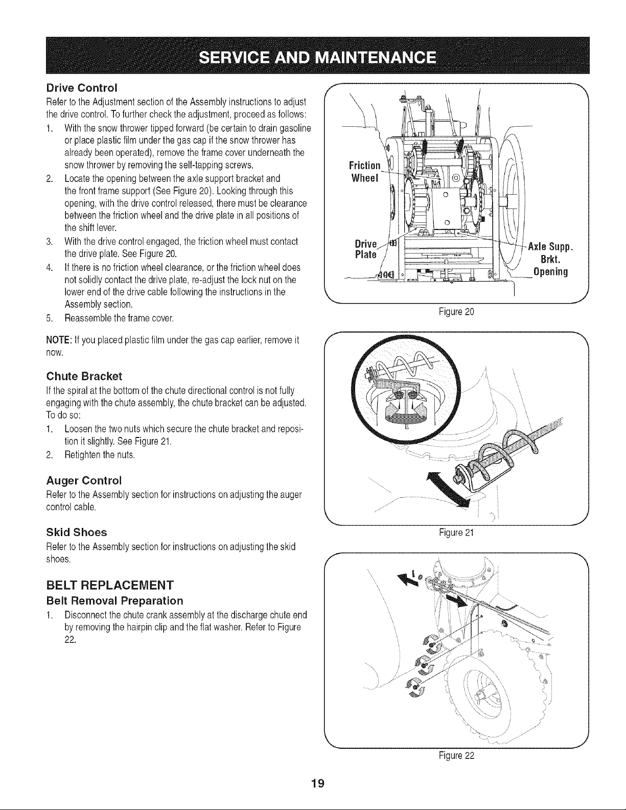
Drive Control
RefertotheAdjustmentsectionoftheAssemblyinstructionsto adjust
thedrivecontrol.Tofurtherchecktheadjustment,proceedasfollows:
1. Withthesnowthrowertippedforward(becertaintodraingasoline
orplaceplasticfilm underthegascapifthesnowthrowerhas
alreadybeenoperated),removetheframecoverunderneaththe
snowthrowerbyremovingtheself-tappingscrews.
2. Locatetheopeningbetweentheaxlesupportbracketand
thefrontframesupport(SeeFigure20). Lookingthroughthis
opening,withthe drivecontrolreleased,theremustbeclearance
betweenthefrictionwheelandthedriveplatein allpositionsof
theshiftlever.
3. Withthedrivecontrolengaged,thefrictionwheelmustcontact
thedriveplate.SeeFigure20.
4. If thereis nofrictionwheelclearance,orthefrictionwheeldoes
notsolidlycontactthedriveplate,re-adjustthelocknutonthe
lowerendofthedrivecablefollowingtheinstructionsinthe
Assemblysection.
5. Reassembletheframecover.
f --,,
Friction
Wheel
Drive_qj
Plate!
J
Figure20
NOTE:If youplacedplasticfilmunderthegascapearlier,removeit
now.
Chute Bracket
If thespiralatthebottomofthechutedirectionalcontrolisnotfully
engagingwiththechuteassembly,thechutebracketcanbeadjusted.
Todoso:
1. Loosenthetwonutswhichsecurethechutebracketandreposi-
tionitslightly.SeeFigure21.
2. Retightenthenuts.
Auger Control
RefertotheAssemblysectionforinstructionsonadjustingtheauger
controlcable.
Skid Shoes
RefertotheAssemblysectionforinstructionsonadjustingtheskid
shoes.
BELT REPLACEMENT
Belt Removal Preparation
1. Disconnectthechutecrankassemblyat the dischargechuteend
byremovingthehairpinclipandtheflat washer.RefertoFigure
22.
f
/
J
Figure21
f
19
Figure22
....JJ
i/
jl
J
Page 20
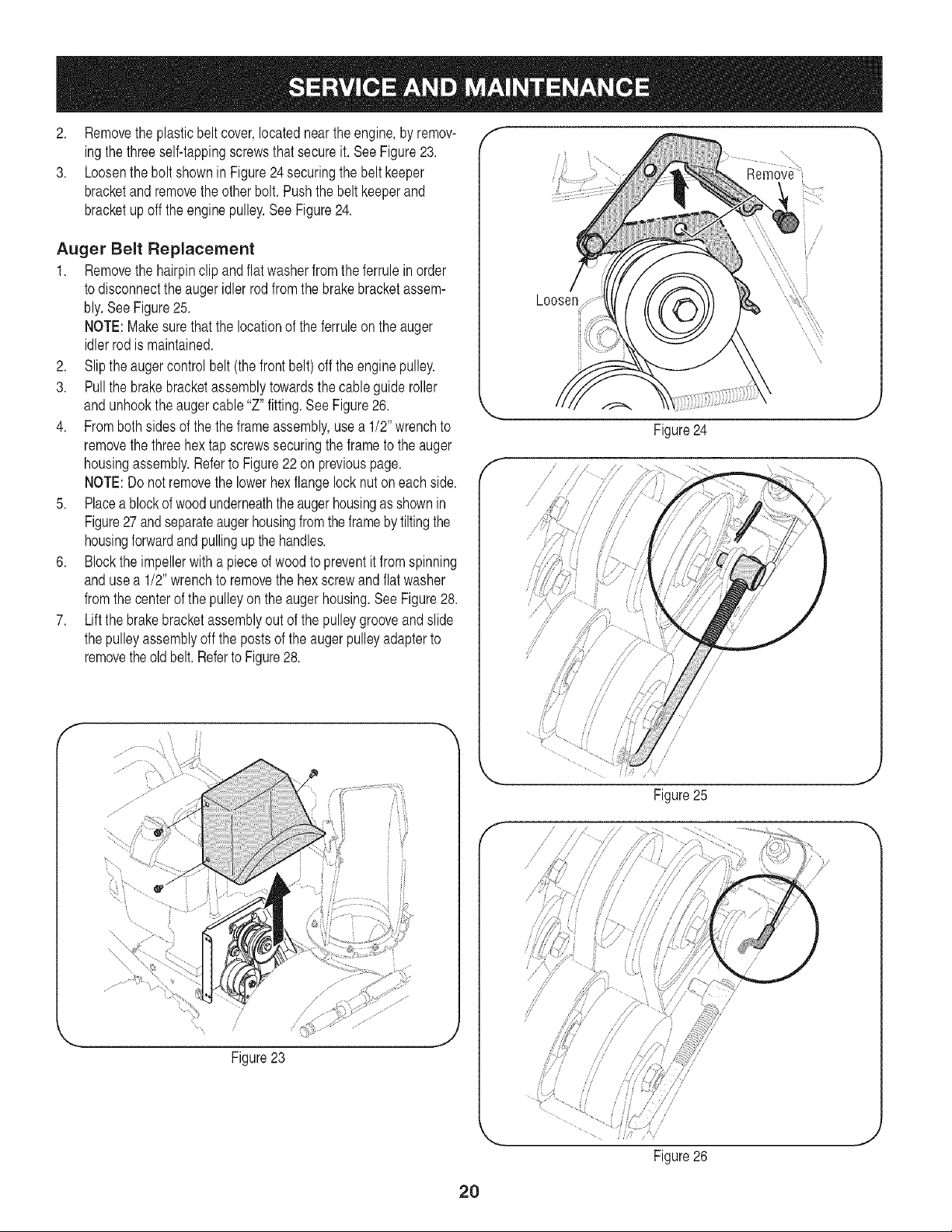
2. Removethe plasticbeltcover,locatedneartheengine,byremov-
ingthethreeself-tappingscrewsthatsecureit.SeeFigure23.
3. Loosentheboltshownin Figure24securingthebeltkeeper
bracketandremovetheotherbolt. Pushthe beltkeeperand
bracketupofftheenginepulley.SeeFigure24.
Auger Belt Replacement
1. Removethe hairpinclipandflatwasherfromthe ferruleinorder
todisconnecttheaugeridlerrodfromthe brakebracketassem-
bly.SeeFigure25.
NOTE:Makesurethatthe locationoftheferruleonthe auger
idlerrodis maintained.
2. Sliptheaugercontrolbelt(thefrontbelt)offtheenginepulley.
3. Pullthebrakebracketassemblytowardsthecableguideroller
andunhooktheaugercable"Z"fitting.SeeFigure26.
4. Frombothsidesofthe the frameassembly,usea 1/2" wrenchto
removethethreehex tapscrewssecuringtheframetothe auger
housingassembly.Referto Figure22on previouspage.
NOTE:Do notremovethelowerhexflangelocknutoneachside.
5. Placeablockofwoodunderneaththe augerhousingasshownin
Figure27andseparateaugerhousingfromtheframebytiltingthe
housingforwardandpullingupthehandles.
6. Blockthe impellerwithapieceofwoodtopreventitfromspinning
andusea 1/2"wrenchto removethehexscrewandflatwasher
fromthecenterofthe pulleyon theaugerhousing.SeeFigure28.
7. Liftthebrakebracketassemblyoutofthepulleygrooveandslide
thepulleyassemblyoffthe postsof the augerpulleyadapterto
removetheoldbelt.RefertoFigure28.
f --,,
/
/
Loosen
/
//
Figure24
i
,,.-/"
Figure23
20
//
Figure25
f
/" /, //
// //
// ,/
/
J
Figure26
Page 21
NOTE:Thepulleyadaptermayslideoffthe augerinputshaftwhen
removingthepulley.Useextracautiontoensuretheadapterdoesfall
and/orget damagedwhenremovingthepulley.
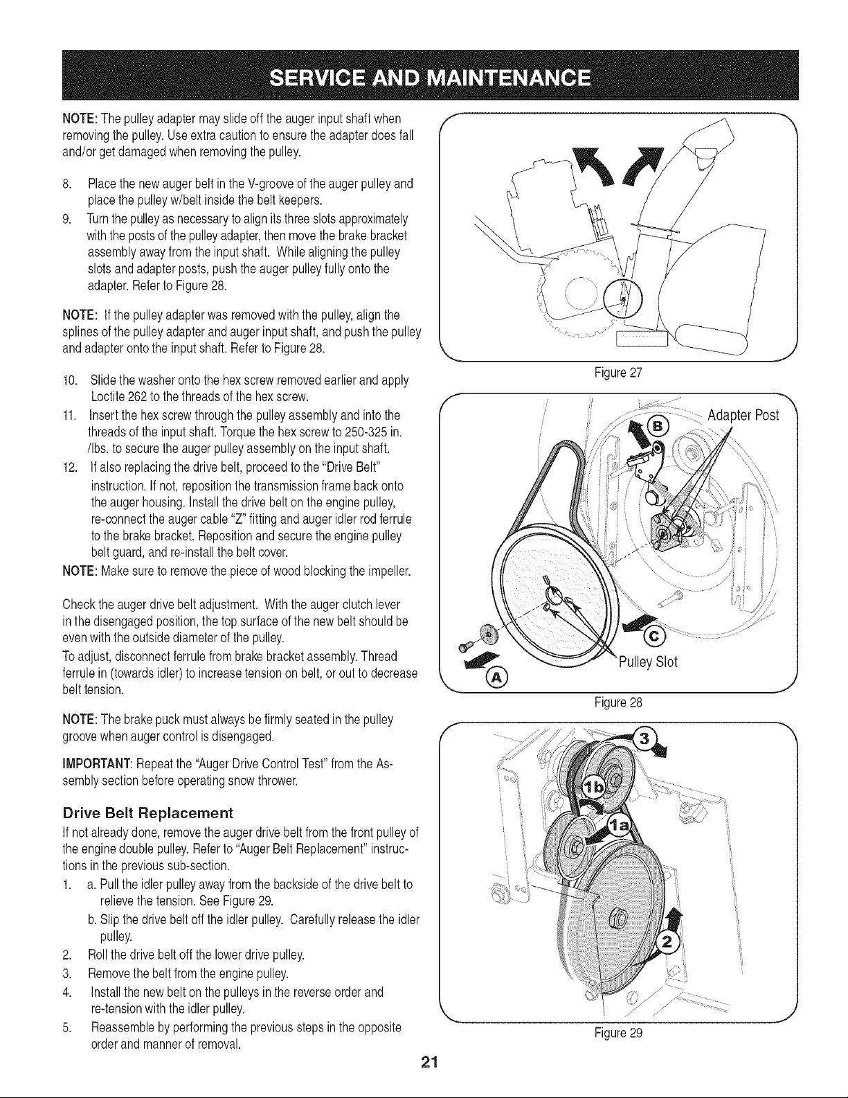
8,
Placethe newaugerbeltin the V-grooveof the augerpulleyand
placethe pulleyw/beltinsidethe beltkeepers.
9.
Turnthepulleyasnecessarytoalignitsthreeslotsapproximately
withthepostsofthepulleyadapter,thenmovethe brakebracket
assemblyawayfromtheinputshaft. Whilealigningthepulley
slotsandadapterposts,pushtheaugerpulleyfullyontothe
adapter.Referto Figure28.
NOTE: If thepulleyadapterwasremovedwiththepulley,alignthe
splinesofthepulleyadapterandaugerinputshaft,andpushthepulley
andadapterontothe inputshaft.Referto Figure28.
10. Slidethewasherontothe hexscrewremovedearlierandapply
Loctite262to the threadsofthehexscrew.
11. Insertthe hexscrewthroughthepulleyassemblyandintothe
threadsoftheinputshaft.Torquethe hexscrewto 250-325in.
/Ibs.tosecuretheaugerpulleyassemblyontheinputshaft.
12. If alsoreplacingthedrivebelt,proceedtothe"DriveBelt"
instruction.If not,repositionthetransmissionframebackonto
theaugerhousing.Installthedrivebelton theenginepulley,
re-connectthe augercable "Z"fittingandaugeridlerrodferrule
tothebrakebracket.Repositionandsecuretheenginepulley
beltguard,andre-installthe beltcover.
NOTE:Makesureto removethepieceof woodblockingthe impeller.
f
Adapter Post
Checktheaugerdrivebeltadjustment.Withtheaugerclutchlever
inthedisengagedposition,thetopsurfaceof thenewbelt shouldbe
evenwiththeoutsidediameterof thepulley.
Toadjust,disconnectferrulefrombrakebracketassembly.Thread
ferrulein (towardsidler)toincreasetensiononbelt,orouttodecrease
belttension.
NOTE:Thebrakepuckmustalwaysbefirmlyseatedinthe pulley
groovewhenaugercontrolisdisengaged.
IMPORTANT:Repeatthe "AugerDriveControlTest"fromtheAs-
semblysectionbeforeoperatingsnowthrower.
Drive Belt Replacement
If notalreadydone,removethe augerdrivebeltfromthefrontpulleyof
theenginedoublepulley.Referto"AugerBeltReplacement"instruc-
tionsinthe previoussub-section.
1. a.Pulltheidlerpulleyawayfromthebacksideofthedrivebelt to
relievethetension.SeeFigure29.
b.Slipthedrivebelt offtheidler pulley.Carefullyreleasetheidler
pulley.
2. Rollthedrivebeltoff thelowerdrivepulley.
3. Removethebeltfromtheenginepulley.
4. Installthenewbelton thepulleysinthereverseorderand
re-tensionwith theidler pulley.
5. Reassembleby performingthepreviousstepsintheopposite
orderandmannerof removal.
,ySlot
Figure28
// ,/ j
Figure29
21
Page 22

CHANGING FRICTION WHEEL
Therubberonthefrictionwheelissubjecttowearandshouldbe
checkedafterthefirst25hoursofoperation,andperiodicallythere-
after.Replacethefrictionwheelifanysignsofwearorcrackingare
found.
1. Drainthegasolinefromthesnowthrower,or placea pieceof
plasticunderthe gas cap.
2. Tipthesnowthrowerupandforward,sothat itrestsonthe
housing.
3. Removescrewsfromtheframecoverunderneaththesnow
thrower(referto Figure30). Removetherightwheelfromthe
axle.
4. Usinga 3/4"wrench,holdthe hex shaftandremovethe hex
screwandbellevillewasherand bearingfromleft sideofthe
frame.Referto Figure31.
5. Holdingthefrictionwheelassembly,slidethe hex shaftout of
thefriction wheelassemblyandtherightside oftheframe.The
spacerontheleftsideofthehexshaft will falland thesprocket
shouldremainhanginglosein thechain.
6. Liftthefrictionwheelassemblyout betweentheaxleshaftand
thedrive shaftassemblies.
7. Removefourscrewssecuringthefrictionwheeltothehub
assembly(referto Figure32).Discardoldfrictionwheel.
8. Reassemblethenewfrictionwheelontothehubassembly,
tighteningthefourscrewsin rotationandwithequalforce.It is
importanttoassemblethefrictionwheelsymmetricallyforproper
functioning.
f --,,
[_ ?q ,gr
i f f _
Figure30
f
RemoveHexScrew
BellevilleWasher
[,
FrictionWheelAss'y.
SlideHex
ShaftOut
RightSide
22
RexShaft
,J
Figure31
,J
Figure32
Page 23

9. Repositionthefrictionwheelassemblyinthe snowthrowerframe.
Insertthe pinfromtheshiftarm assemblyintothe frictionwheel
assemblyandholdassemblyinposition.RefertoFigure33.
10. Slidethehexshaftthroughtherightsideoftheframetowardthe
leftsideandthroughthefrictionwheelassembly.
11. Aftermakingcertainthatthechainison boththe largeandthe
smallsprocket,alignthe hexshaftwiththehexhubofthesmall
sprocket,andslidetheshaftthroughthesprocket.
NOTE:If thesprocketfellfromthesnowthrowerwhile removingthe
hexshaft,placethe sprocketon thechain.Realignthesprocketon the
chainwiththehexhubfacingtherightsideof unit.Positionthehex
hubofthesprockettowardthefrictionwheelwhenslidingthesprocket
ontothe hexshaft.
12. Slidethespacerontotheendofthe hexshaft.
13. Alignthebearingon therightendof the hexshaftwiththe hole
in the rightside oftheframe,thenpushthehexshafttotheleft
intopositionintheframe.
14. Slidethebearingontotheleftendof the hexshaftandpressinto
theholeontheleftside theframe.
15. Placethe bellevillewasher(roundedsidetowardhead)ontothe
hexscrew removedearlier,and insertthescrewintothethreaded
holeofthehexshaft.
16. Graduallytightenthehexscrewto fullyseatthe bearingsineach
sideof theframeandtosecurethehexshaft.
MAINTENANCE SCHEDULE
©
Figure33
17. Positionthe framecoveron thebottomoftheframeand secure
withtheself-tappingscrews.Pivotthesnowthrowerdowntoit
normaloperatingposition.
NOTE:Ifyouplacedplasticfilmunderthegascap,becertainto
removeit.
Beforeperforminganytypeofmaintenance/service,disengageall
controlsandstoptheengine.Waituntilallmovingpartshavecometo
acompletestop.Disconnectsparkplugwireandgrounditagainstthe
enginetopreventunintendedstarting.Alwayswearsafetyglassesduring
operationorwhileperforminganyadjustmentsorrepairs.
EachUse
1st5- 8hours
25 hours
50 hours
Annuallyor100hours
BeforeStorage
' Underheavyloador inhightemperatures
1. Engineoillevel
2. Looseormissinghardware
3. Unitandengine.
1. Engineoil
1. Engineoi11
2. Aircleaner
3. Controllinkagesand pivots
1. Engineoil
1. Sparkplug
1. Fuelsystem
1. Check
2. Tightenor replace
3. Clean
1. Change
1. Change
2. Cleanor replace
3. Lubewithlightoil
1. Change
1. Clean,replace,re-gap
1. Runengineuntil itstopsfromlackof
Followthemaintenanceschedulegivenbelow.Thischartdescribes
serviceguidelinesonly.UsetheServiceLogcolumntokeeptrackof
completedmaintenancetasks.To locate the nearest Sears Service
Center or to scheduleservice,simplycontactSearsat
1-800-4-MY-HOME®.
fueloraddagasolineadditivetothe
gasin thetank.
23
Page 24

If the snowthrowerwill notbeusedfor30daysor longer,or if itistheendofthesnowseasonwhenthelastpossibilityof snowisgone,the
equipmentneedsto bestoredproperly.Followstorageinstructionsbelowto ensuretopperformancefromthesnowthrowerformanymoreyears.
PREPARING ENGINE
Short=Term Storage
It is importanttopreventgumdepositsfromforminginessentialfuel
systempartsof the enginesuchasthecarburetor,fuel filter,fuelhose,
ortankduringshort-termstorage(15-30days).Topreventthis,treat
thefuelsystemusingafuelstabilizer.
Fuelstabilizer(suchasSTA-BILTM or ULTRA-FRESHTM) is anaccept-
ablealternativein minimizingthe formationof fuelgumdepositsduring
storage.Addstabilizertogasolineinfueltankorstoragecontainer.
Alwaysfollowmixratiofoundonstabilizercontainer.Runengineat
least10minutesafteraddingstabilizertoallowitto reachthecarbure-
tor.
Neverstoresnowthrowerwithfuelin tankindoorsorin poorlyventi-
latedareas,wherefuelfumesmayreachanopenflame,sparkor pilo
ghtason afurnace,waterheater,clothesdryerorgas appliance.
Alcoholblendedfuels(calledgasoholor usingethanolor methanol)
canattractmoisturewhichleadstoseparationandformationofacids
duringstorage.Acidicgascandamagethefuelsystemofan engine
[wh e nstorage.
PREPARING SNOW THROWER
,, Whenstoringthe snowthrowerin anunventilatedor metalstor-
ageshed,careshouldbetakentorustprooftheequipment.Using
a light oilorsilicone,coattheequipment,especiallyanychains,
springs,bearingsandcables.
,, Removealldirt fromexteriorof engineand equipment.
,, Followlubricationrecommendations.
,, Storeequipmentin a clean,dryarea.
Long=Term Storage
Toavoidengineproblems,thefuel systemshouldbeemptiedbefore
storagefor 30daysor longer.
Fuelleft inengineduringwarmweatherdeterioratesandwillcause
seriousstartingproblems.
1. Runtheengineuntilthefueltankisemptyanditstops duetolack
offuel.Donotattemptto pourfuelfromtheengine.
carburetor inthefueltank
pNeveruseengineor cleaningproducts or
ermanentdamagemayoccur, j
2. Removethesparkplugandpourone (1)ounceof engineoil
throughthesparkplugholeintothe cylinder.Coversparkplughole
witharagandcranktheengineseveraltimestodistributetheoil.
Replacesparkplug.
J
/
24
Page 25

Beforeperforminganytypeofmaintenance/service,disengageall
controlsandstoptheengine.Waituntilallmovingpartshavecometo
a completestop.Disconnectsparkplugwireandgrounditagainstthe
enginetopreventunintendedstarting.Alwayswearsafetyglassesdurin(
operationorwhileperforminganyadjustmentsorrepairs.
Thissectionaddressesminor serviceissues,Tolocatethe nearestSears ServiceCenter or to scheduleservice,simply contactSears
at 1-800-4-MY-HOME®.
o =
Enginefailsto start
Enginerunserratically
Engineoverheats
Excessivevibration
1. Chokecontrolnotin ONposition
2. Sparkplugwiredisconnected
3. Faultysparkplug
4. Fueltankemptyorstalefuel
5. Enginenotprimed.
6. Safetykeynotinserted.
1. Enginerunningon CHOKE
2. Stalefuel
3. Wateror dirtinfuelsystem
4. Carburetoroutof adjustment
1. Carburetornotadjustedproperly
1. Loosepartsordamagedauger
1. MovechokecontroltoONposition.
2. Connectwiretosparkplug.
3. Clean,adjustgap,or replace.
4. Filltankwithclean,freshgasoline.
5. PrimeengineasinstructedintheOperationSection.
6. Insertkeyfullyintothe switch.
1. MovechokecontroltoOFFposition.
2. Filltankwithclean,freshgasoline.
3. Drainfueltank.Refillwith freshfuel.
4. ContactyourSearsParts&RepairCenter.
1. ContactyourSearsParts& RepairCenter.
1. Stopengineimmediatelyanddisconnectsparkplug
wire.Tightenall boltsandnuts.If vibrationcontinues,
haveunit servicedbya SearsParts& RepairCenter.
Lossof power 1. Sparkplugwireloose.
2. Gascapventholeplugged.
1. Connectandtightensparkplugwire.
2. Removeiceandsnowfromgas cap.Becertainvent
holeisclear.
Unitfailsto propelitself 1. Drivecablein needofadjustment
1. Adjustdrivecontrolcable.Referto Serviceand
Maintenancesection.
2. Drivebeltlooseordamaged
2. Replacedrivebelt.RefertoServiceand Mainte-
nancesection.
Unitfailsto dischargesnow 1. Chuteassemblyclogged.
1. Stopengineimmediatelyanddisconnectsparkplug
wire.Cleanchuteassemblyandinsideofauger
housingwithclean-outtool ora stick.
2. Foreignobjectlodgedinauger.
2. Stopengineimmediatelyanddisconnectsparkplug
wire.Removeobjectfromaugerwithclean-outtool
or astick.
3. Augercableinneedofadjustment.
3. Adjustaugercontrolcable.Referto Assembly
section.
4. Augerbeltlooseordamaged.
4. Replaceaugerbelt.Referto ServiceandMainte-
nancesection.
5. Shearpin(s)sheared.
5. Replacewithnewshearpin(s).
25
Page 26

Craftsman Snow Thrower Model 247.88045
26
Page 27

Craftsman Snow Thrower Model 247.88045
D" Q 0
05244B Housing,Bearing
2. 05845C Housing,Bearing
3. 618-04515 GearBoxAssembly,Auger
4. 618-0281A BracketAssy,AugerBrake
5. 684-0090B Impellar,16"
6. 684-04224 Housing,Auger- 45"
7. 684-04151 SpiralAssy,LH
8. 684-04152 SpiralAssy,RH
9. 710-1245B Screw,5/16-24x.875
10. 710-0389 Bolt,Carriage,3/8-16x .750
11. 710-0451 Screw,Carriage,5/16-18x .75
12. 710-0459A Scr,HexCap,3/8-24x1.5
13. 710-0376 Scr,HexCap,5/16-18x 1.00
14. 710-04484 Screw,5/16-18x .750
15. 726-04012 Nut,Push
16. 629-0071 ExtensionCord,110V
17. 710-3168 Bolt,Carriage,3/8-16x 1.0
18. 710-04606 Screw,5/16-18x .4300
19. 711-0677 Ferrule
20. 712-0116 Nut,HexLock,3/8-24
21. 712-04063 Nut,FlngeLk,5/16-18
22. 712-04065 Nut,Fig Lk,3/8-16
23. 741-0217 Sleeve
24. 714-0104 Pin,InternalCotter
25. 714-0126 Key,HiPro,3/16x3/4
26. 714-0135 Key,Woodruff,I/4x 3/4
27. 714-04040 Pin,BowtieCotter
28. 715-0118 Pin,Spirol,5/16x 1.75
29. 725-0157 Tie,Cable
30. 731-1696A Adapter,Chute,6"
31. 738-0275 Shf,Gear,Worm
32. 731-05163 Spacer,1.0x 1.5x 1
33. 731-2635 Clip,Mounting
34. 731-2643 Tool,Cleanout
35. 732-0858 Spring,Extension
36. 736-0159 Washer,.349x .879x.063
37. 736-0174 Washer,.625x .885x.015
38. 736-0505 Washer,Flat,.34x 1.50x .150
D _ 0 Q
750-04020 Spacer,1.004x 1.375x .25
40. 721-0146 OilSeal
41. 736-3008 Washer,.344x .75x.12
42. 736-3046A Washer,1.01x 1.86x.06
43. 738-0281 Screw,Shoulder,.625x.17
44. 738-04155 Pin,Shear,.25x 1.75
45. 738-04159 Axle,Spiral,45"
46. 741-0192 Bearing,Flangew/Flats
47. 741-04024 Bearing,SelfAligning
48. 741-0475 Bushing,Nylon
49. 741-0494 Bushing,Flange,1.051x 1.16
50. 747-0980A Rod,AugerIdler
51. 721-0325 Plug
52. 754-0222A V Belt,l/2 x44
53. 756-0178 Pulley,FlatIdler,2.75OD
54. 756-04244A Pulley,AugerDrive,10.0
55. 784-0385B Bracket,AugerIdler
56. 790-00264A Bracket,GearBox Support
57. 784-5123 Bracket,ChuteCrank
58. 710-0276 Screw,Carriage,5/16-18x 1.00
59. 790-00181 DriftCutter
60. 790-00280 Plate,Shave,45"
61. 741-0184 Brg,Thrust
62. 784-5697 Shoe,Skid
63. 749-04384 SupportTube
64. 710-3008 Screw,5/16-18x.75
65. 748-04067A Pulley,Adapter,.75Dia.
66. 618-0246 HsgAssyAugerRH(Inc.40&70)
67. 618-0247 HsgAssyAugerLH(Inc.40&70)
68. 710-1260A Screw,LD,5/16-18x .750
69. 711-04714 Shf,Drive,Auger
70. 741-0670 FlangeBearing
71. 716-0111 Ext,Ret,Ring
72. 717-1425 Gear,Worm,LH
73. 721-0145 Seal,Oil
74. 736-0266 Washer,Flat,1.52IDx 2.00D
75. 736-0291 Washer,Flat,.88IDx.38OD
76. 717-0299 Gear,Worm,DblThread
27
Page 28

Craftsman Snow Thrower Model 247.88045
®
\
28
Page 29

Craftsman Snow Thrower Model 247.88045
D" i Q
625-0007A Assembly,Light
2. 646-0012 CableAss'y,Auger/Drive
3. 684-0053B Crank,Chute,26.0
4. 705-5218 Handle,Engage,RH
5. 705-5219 Handle,Engage,LH
6. 705-5266 Bracket,ChuteCrank
7. 710-0458 Screw,Cam, 5/16-18x 1.75
8. 710-0572 Screw,Cam, 5/16-18x 2.5
9. 710-1003 Screw,#10-16x .625
10. 710-1625 Screw,#10-24x 1.75
11. 710-04682 Screw,Hex,3/8-16x2.00
12. 710-3118 Screw,Hex,3/8-16x 1.00
13. 710-3015 Screw,Hex,1/4-20x.75
14. 711-0677 Ferrule,5/16-18x.312Dia
15. 784-5679 Brkt.,HandleSupport- LH
16. 712-04064 Nut,HexFlange,1/4-20
17. 712-3068 Nut,HexLock,5/16-18GR5
18. 714-0101 Pin,InternalCotter
19. 714-0104 Pin,InternalCotter
20. 720-0201A Knob,Crank
21. 720-04039 Knob,Shift
22. 720-0284 Knob,Wing,5/16-18
23. 725-0157 Tie,Cable
24. 784-5682 Brkt.,HandleSupport- RH
25. 784-5681 Brkt.,HandleSupport- LH
26. 726-0100 Cap,Push,3/8
27. 731-2298 Panel,Handle
28. 736-0105 Wash,Bell,.375x .87x .063
29. 736-0185 Wash,Fl.,.375x .738x.063
30. 736-0242 Wash,Bell,.34x .872x .06
31. 736-0275 Wash,FI,.344x .688x .065
32. 741-0475 Bushing,Plastic,.38ID
33. 746-0950A CableAssembly,Trigger
34. 747-0624 Rod,ChuteCrank
35. 747-0983A Rod,LowerShift
36. 747-0997 Rod,UpperShift
37. 784-5680 Brkt.,HandleSupport- RH
38. 749-0989A Handle,UpperLH
39. 749-0990A Handle,UpperRH
40. 749-0991 Handle,Lower
41. 750-0963 Connector,ShiftRod
D _ O Q
684-0102A Panel,Handle
43. 710-0276 Screw,Carr,5/16-18x1.0
44. 710-0458 Screw,Carr.,5/16-18x 1.75
45. 710-0459A Screw,Hex,3/8-24x 1.5
46. 710-0597 Screw,Hex,1/4-20x 1.0
47. 710-0599 Screw,Hx,1/4-20x.5
48. 710-0805 Screw,Hex,5/16-18x 1.5
49. 710-0895 Screw,Hx,1/4-15x.75
50. 711-0653 Pin,Clevis,.312x1.0
51. 712-0116 Nut,Insert,3/8-24
52. 712-04063 Nut,FlngeLk,5/16-18
53. 714-0507 Pin,Cotter,3/32x .75
54. 731-08460 Chute,Upper,6.0
55. 731-0851A FlangeKeeper,Chute
56. 731-0903D Chute,Lower
57. 731-13130 Cbl.Guide,ChuteTilt
58. 732-0145 Spring,Compression
59. 732-0193 Spring,Compression
60. 732-0746 Spring,Torsion
61. 735-0199A Bumper,Rubber
62. 784-5619B Handle,Shift
63. 736-0231 Wash,FI,.344x 1.125x.12
64. 736-0119 Washer,Lock,5/16
65. 736-0509 Wash,FI,.35Sqx .72x .134
66. 746-0902 Cable,ChuteControl,66"
67. 746-0903 Cable,ChuteControlw/Clip,
68. 747-0877 Rod,Cam
69. 748-0362 Cam,HandleLock
70. 748-0363 Pawl,HandleLock
71. 784-5594 Bracket,Cable
72. 784-5604A Handle,ChuteTilt
73. 736-0159 Washer,Flat,.349x .879x .063
74. 705-5217 Bracket,Mount,Lamp
75. 710-0451 Bolt,Carriage,5/16-18x.750
76. 710-1240 Screw,M4x.7
77. 725-1658 Lamp
78. 725-1669 Housing,Lamp
79. 725-04220 Harness
80. 731-1364 Housing
81. 735-0225 Grommet
29
Page 30

3O
Page 31

Craftsman Snow Thrower Model 247.88045
I _ O Q
05244B Housing,Bearing
2. 618-0279 Dogg,SteeringDrive,LH
3. 618-0280 Dogg,SteeringDrive,RH
4. 618-0282E ShaftAssembly,Steering
5. 618-04178 Assembly,FrictionWheel
718-04034 Wheel,Friction,Bonded
710-0896 Screw,HexWash
6. 684-0118B Bracket,AugerActuator
7. 684-0119B Bracket,DriveActuator
8. 684-04235 Sprocket,32T
9. 684-0161 Arm,Shift
10. 684-04212 Brkt, FrictionDriveSuprt.
11. 684-04103 RodAssembly,Shift
12. 784-0385B Brkt.,Idler,Auger
13. 710-0538 Screw,HexCapLock,
14. 756-0178 Idler,Flat,2.75OD
15. 754-0222A V-Belt,1/2x 44.0
16. 750-04718 Spcr.,.51IDx 3.66Lg.
17. 710-1652 Screw,HexWash.
18. 750-04717 Spcr.,.51IDx 7.895Lg.
19. 710-3001 Screw,HexCap,3/8-16
20. 750-04703 Spcr.,1.0IDx 1.50OD
21. 710-0788 Screw,Hex,1/4-20x 1.00
22. 710-0459A Screw,3/8-24x 1.50
23. 711-04279 Shaft,HexDrive
24. 711-04605 Shaft,Actuator
25. 716-04048 Ring,Retainer
26. 712-0116 Nut,HexInsertJamLock
27. 712-0138 Nut,Hex,1/4-28GR5
28. 784-5726 Bracket,Idler,Drive
29. 712-04065 Nut,HxFlngeInsertLk
30. 712-0413 Nut,HxInsertJamLk
31. 710-04484 TT Screw,5/16-18x .750
32. 712-0717 Nut,Insert3/8-16
33. 713-0284 Chain,Endless,#41x36L
34. 713-0286 Chain,#420x40L
35. 713-04015 Sprocket,#41x lOT
36. 714-0135 Key,Woodruff
37. 714-0104 Pin,InternalCotter
D _ O i
716-0104 E-Ring
39. 714-0388 Key,Hi-Pro,3/16x 5/8
40. 716-0136 Ring,Retaining
41. 717-0302 Plate,Drive
42. 732-0121 Spring,Extension
43. 732-0209 Spring,Extension
44. 756-0241B Pulley,Dbl,3.25OD
45. 736-0158 Washer,Lock,5/8
46. 756-0240 Pulley,FlatIdler,3.00D
47. 634-0225A WheelAss'y.- LH
634-0226A WheelAss'y.-RH
734-2031 Tire
734-0255 Valve
741-0246A Bearing
48. 711-04615 Pin,Clevis
49. 736-0242 Wsh,Bell.,.34x.872x.06
50. 736-0300 Wash,.406x .875x .059
51. 736-0329 Washer,Lock,1/4
52. 714-0149B Pin,InternalCotter
53. 737-3000 Fitting,Lube,3/16Drive
54. 738-0143 Screw,Shldr.,.498 x .34
55. 738-0279 Spindle,DrivePlate
56. 738-0924A Screw,HexShldr.,1/4-28
57. 741-0163A Ass'y,Bearing/Housing
58. 741-04108 Bearing,HexFlange
59. 741-04025 Bearing,SelfAligning
60. 741-04076 Bearing,Ball
61. 741-0563 Bearing,Ball
62. 741-0748 Bush,Fig,.5IDx .627OD
63. 746-0949A Cable,Steering
64. 746-0951 Cable,AugerIdler
65. 747-0973 Rod,DriveClutch
66. 750-0903B Spcr.,.514x .632x2.44
67. 750-0997 Spacer,.675x 1.0x.23
68. 750-1302B Spcr,.6725x1.125x 2.48
69. 756-0344 Pulley,Drive
70. 756-0625 Roller,Cable
71. 790-00257 Cover,UpperFrame
72. 790-00259 Cover,LowerFrame
31
Continuedonfollowingpage
Page 32

Craftsman Snow Thrower Model 247.88045
Continuedfrom previouspage
711-04606 Axle,Wheel,45"
74. 790-00255A Frame,Transmission
75. 784-0406A Bracket,FrameSupport
76. 784-0407 Bracket,AxleSupport
77. 790-00254 Bracket,BeltCover
78. 710-0191 Screw,3/8-14x 1.25GR8
79. 710-0237 Screw,5/16-24x .625
80. 710-0607 Screw,HxWashHdTapp
81. 710-1245B Screw,HxCap5/16-24
82. 710-0654A Screw,3/8-16x 1.00
83. 736-0173 Wsh,Flat,.28 x .74x .063
84. 714-0118 Key,Square,1/4x 1.5
85. 790-00167A Brkt.,Belt,Keeper
86. 731-2531 Cover,Belt
87. 732-0303 Spring,Extension
88. 732-0705 Guide,ChuteCable
89. 736-0247 Washer,Flat,.406x 1.25
90. 748-0234 Spacer,Shoulder
91. 736-0159 Washer,Flat,.349x .879
92. 754-0131 V-Belt,3/8 x35.5
93. 712-04064 Nut,FigLk, 1/4-20
94. 726-0221 Nut,Spd.
95. 735-04099 Plug,3/8 ID
D _ J Q
32
Page 33

Craftsman Engine Model OH358SA=223828 For Snow Thrower Model 247.88045
154A
342A
300A
335A,
47
169,
220 / / '''_" _" "
"._ _ ""-.206
328 420 "_" 92'
186B
33
35O
!
351
37O
- 203
,178
/
990
Page 34

Craftsman Engine IVlodel OH358SA=223828 For Snow Thrower IVlodel 247.88045
37083
2 27652
3 650820
4 0
5 30969
14 28277
14A 651057
15 35685
16 35686A
17 29916
18 651028
19 35688
20 35319
25 37861
26 650561
28 30322
30 35680A
31 35327
35 29826
36 29918
37 29216
38 29642
40 35777A
40 35776A
42 35780
42 35779
43 35772
45 36898A
47 651033A
48 35313A
50 35682A
51 35315A
60 35316A
65 30200
69 35683
D _ J m
Cylinder(Incl.2, 20, 72&80)
DowelPin
Screw,1/4-20x 1/2"(UpperMountingScrews
for120-VoltElectricStarterMotor)
Oil DrainExtensionNotAvailable
ExtensionCap,1/4-18NPT
FlatWasher
Washer
GovernorRod (Incl.14& 38)
GovernorLever(Incl.212A)
GovernorLeverClamp
Screw,T-15,8-32x7/16"
ExtensionSpring
Oil Seal
BlowerHousingBaffle(Incl.325)
Screw1/4-20x 19/32"
LockNut,8-32
Crankshaft
CounterbalanceGear
Screw,10-32x 3/4"
LockWasher#8
LockNut,10-32
RetainingRing
Piston,Pin&RingSet(.010"OS)(Incl.41,42
& 43)
Piston,Pin&RingSet(Std) (Incl.41,42& 43)
RingSet (.010"OS)
RingSet (Std.)(3-5/16")
PistonPinRetainingRing
ConnectingRodAssembly(incl.47& 49)
ConnectingRodBolt(1/4-20x 1-5/16")
ValveLifter
Camshaft(MCR)
CounterbalanceWeight
BlowerHousingExtension
Screw,10-24x9/16"
CylinderCoverGasket
35684A
71 35377
80 35751
81 35479A
82 35321
83 35322
84 29193
86 650833
87 650832
89 32589
90 611093
92 650880
93 650881
100 35135A
101 611289
102 651024
103 651007
110 35187
110A 37047
119 36932
120 37491
125 36936
125 36934
126 36937
126 36935
127 650691
128 650690
130 650697A
135 34645
150 33507
151 33508
151A 35862
153 35949
154 651105
D _ e ID
CylinderCover(Incl.14,15,20,38
CrankshaftBushing
GovernorShaft
Washer
GovernorGearAssembly
GovernorSpool
RetainingRing
Screw1/4-20x 1-3/16"
Screw,1/4-20x 1- 11/16"
FlywheelKey
Flywheel(3Amp,w/ringgear)
BellevilleWasher
FlywheelNut(5/8-18)
SolidStateIgnition(Incl. 101)
SparkPlugCover
SolidStateMountingStud
Screw,T-15,10-24x 15/16"
GroundWire(13.65"long- darkgreen- 90°
female&2 maleblades)
GroundWire(10.50"withmale&femaleflag
terminals)
CylinderHeadGasket
CylinderHead(Incl. 151A&270A)
ExhaustValve(1/32"OS)
ExhaustValve(Std)
IntakeValve(1/32"OS)
IntakeValve(Std.)
FlatWasher
BellevilleWasher
Screw,5/16-18x2-1/2"
ResistorSparkPlug(RN4C)alsoavailablein
PackagedPart#740069
ValveSpring
ValveSpringKeeper
IntakeValveSeal
PushRod Guide
RockerArmStud
34
Page 35

Craftsman Engine IVlodel OH358SA=223828 For Snow Thrower IVlodel 247.88045
D _ Q ®
35950 RockerArm
156 37843 RockerArmBearing
157 650586 JamNut,5/16-24
158 35466 PushRod
159 35952 RockerArmCoverGasket
160 35953A RockerArmCover
161 30063 Screw,T-30,1/4-20x 1/2"
161A 651034 ValveCoverMountingStud
169 27896A ValveCoverGasket
170 28423 BreatherBody
171 28424 BreatherElement
172 28425 ValveCover
173 35350 BreatherTube
174 650128 Screw,10-24x 1/2"
178 29752 Nut&LockWasher1/4-28
180 37101 BlowerHousingExtension
183 34583A ChokeBracket
184 33263 Carburetor-to-IntakePipeGasket
185 37085 IntakePipe
186 35691 GovernorLink
186B 36653 ChokeSpring
200 35702 ManualControlBracket(Incl.203,204&206)
203 31342 CompressionSpring
204 651029 Screw,T-IO,5-40x 7/16"
206 610973 Terminal
207 35692 ThrottleLink
212 30773A Bushing(Incl.14A&213)
212A 36288 Bushing
212B 651017 Washer
213 650930 Screw,10-32x 5/8"
215 35440 ControlKnob
216 35679 R.RM.AdjustingLever
219 35689 ChokeRod
220 35438 ControlKnob
223 650971 Screw,T-30,5/16-18x7/8"
224 33515A IntakePipeGasket
238 28820 Screw,10-32x 1/2"
260 37092A BlowerHousing
D _ O Q
651084 Screw,5/16-18x9/16"
265 37086 CylinderHeadCover
266 650876 Screw,5/16-18x 1-9/32"
269 35762 ExhaustManifoldGasket
270 37263 ExhaustManifold
270A 35829A ExhaustPortLiner
271 35293 LockingPlate(Manifold)
275 37264 Muffler
276 35348 LockingPlate
277A 650877 Screw,5/16-18x4-1/2"
280 37265 HeatShield
285 35985C StarterCup
290 37964 FuelLine(32.0"length)
292 26460 FuelLineClamp
293A 650517 Screw,T-30,1/4-20x 27-32"
298 650665 Screw,1/4-15x3/4"
300A 37099A FuelTank(Incl.292&301)
301 37845 FuelCap(RedPlastic)(1-1/2"I.D.)
302 37098 FuelTankExtension
305 35574 Oil FillTube
307 35499 O-Ring
308 35539 FillTubeClip
309 651011 Screw,10-32x5/16"
310 35700 Dipstick
314 650873 Screw,1/4-20x 3/4"
315 611111 AlternatorCoil(18Watt)
328 35062 IgnitionKey(alsoavailablein PackagedPart
#740077)
329A 651060 Screw,8-32x23/64"
335 37096A CarburetorCover
335A 37087 CarburetorCover
338 650821 Screw,10-32x 1/2"
341 37093 FuelTankBracket
342A 792028 Screw,5/16-18x7/8"
343 35079A KeySwitchBracket(Incl.329A)
345 37097 HeatBaffle
350 570682A PrimerAssembly(alsoavailableinPackaged
Part#740101)
35
Page 36

Craftsman Engine IVlodel OH358SA=223828 For Snow Thrower IVlodel 247.88045
32180C
355 590574
361 650990
369 651032
370 37119
370 36695
370
36534
370
36501
370
37226
380
640105
390
590749
396
37105
4OO
36947B
42O
730226A
704 650738
710 36482
711 651019
-- 730286
PrimerLine
StarterHandle(MittenGrip)alsoavailablein
PackagedPart#740053B
Screw,T-30,1/4-20x 15/32"(ElectricStarter
MountingScrews)
Screw,12-16x 5/8"
WarningDecal(Bilingual)
Decal- TecumsehLogoforTopof Recoil
Starter
WarningDecal
Decal- Primer-InternationalSymbol
Decal- SpeedControl,Choke,& Key
Carburetor(Incl.184)
RewindStarter
ElectricStarterMotor(120Volt)(Optional)
GasketSet(Incl.itemsmarked*) (Incl.items
marked*)
SAE5W304-CycleEngineOil(Quart)
(Winter)
Screw,1/4-20x5/8"
CompressionSpring
Screw,T-IO,6-32x41/64"
WinterMaintenanceKitincludes32 oz.
- SAE5W30Oil,sparkplug,switchkey,fuel
stabilizer
EnginePartNumber
913300B
ShortBlockPartNumber
758216
36
Page 37

37
Page 38

(ThispageapplicableintheU.S.A.and Canadaonly.)
Sears, Roebuck and Co., U.S.A. (Sears), the California Air Resources Board (CARB)
and the United States Environmental Protection Agency (U.S. EPA)
Emission ControJ System Warranty Statement (Owner's Defect Warranty Rights and ObJigations)
EMISSIONCONTROLWARRANTYCOVERAGEISAPPLICABLETOCERTI- YEAR1997ANDLATERENGINESWHICHARE PURCHASEDANDUSED
FlEDENGINESPURCHASEDINCALIFORNIAIN 1995ANDTHEREAF- ELSEWHEREINTHE UNITEDSTATES(ANDAFTERJANUARY1,2001 IN
TER,WHICHAREUSEDINCALIFORNIA,ANDTOCERTIFIEDMODEL CANADA).
California and United States Emission Control Defects Warranty Statement
TheCaliforniaAirResourcesBoard(CARB),U.S.EPAandSearsarepleased
toexplaintheEmissionControlSystemWarrantyonyourmodelyear2000and
latersmalloff-roadengine(SORE).InCalifornia,newsmalloff-roadengines
mustbe designed,builtand equippedto meettheState'sstringentanti-smog
standards.ElsewhereintheUnitedStates,newnon-road,spark-ignition
enginescertifiedformodelyear1997andlatermustmeetsimilarstandardsset
forthbythe U.S.EPA.Searsmustwarranttheemissioncontrolsystemonyour
engineforthe periodsoftimelistedbelow,providedtherehasbeenno abuse,
neglector impropermaintenanceof your smalloff-roadengine.Youremis-
sioncontrolsystemincludespartssuchas thecarburetor,aircleaner,ignition
system,mufflerandcatalyticconverter.Alsoincludedmaybeconnectorsand
otheremissionrelatedassemblies.Wherea warrantableconditionexists,Sears
will repairyoursmalloff-roadengineatnocosttoyouincludingdiagnosis,parts
andlabor.
Sears Emission Control Defects Warranty Coverage
Smalloff-roadenginesarewarrantedrelativeto emissioncontrolpartsdefects
fora periodofoneyear,subjecttoprovisionssetforthbelow,Ifanycovered
Owner's Warranty
Asthe smalloff-roadengineowner,youareresponsiblefortheperformanceof
therequiredmaintenancelistedinyour OperatingandMaintenanceInstruc-
tions.Searsrecommendsthatyouretainallyourreceiptscoveringmaintenance
onyoursmalloff-roadengine,butSearscannotdenywarrantysolelyforthe
lackofreceiptsorfor yourfailuretoensuretheperformanceofallscheduled
maintenance.Asthe smalloff-roadengineowner,youshouldhoweverbe
awarethat Searsmaydenyyouwarrantycoverageifyoursmalloff-roadengine
ora parthasfaileddueto abuse,neglect,impropermaintenanceor unap-
partonyourengineisdefective,thepartwillbe repairedor replacedbySears.
Responsibilities
provedmodifications.Youareresponsibleforpresentingyoursmalloff-road
engineto anAuthorizedSearsServiceDealeras soonasaproblemexists.The
undisputedwarrantyrepairsshouldbecompletedina reasonableamountof
time,notto exceed30 days.Ifyouhaveanyquestionsregardingyour warranty
rightsandresponsibilities,youshouldcontacta SearsServiceRepresentative
at 1--800--469--4663.Theemissionwarrantyisa defectswarranty.Defectsare
judgedon normalengineperformance.Thewarrantyis notrelatedto anin-use
emissiontest.
Sears Emission Control Defects Warranty Provisions
ThefollowingarespecificprovisionsrelativetoyourEmissionControlDefectsWarrantyCoverage.ItisinadditiontotheSearsenginewarrantyfornon-regulated
enginesfoundintheOperatingandMaintenanceInstructions.
1. WarrantedParts
Coverageunderthiswarrantyextendsonlytothe parts listed below(the
emissioncontrolsystemsparts)tothe extentthesepartswerepresenton
theenginepurchased.
a. FuelMeteringSystem
,,Coldstartenrichmentsystem
,,Carburetorand internalparts
• FuelPump
b. Airlnduction System
,,Air cleaner
• Intakemanifold
c. IgnitionSystem
,,Sparkplug(s)
• Magnetoignitionsystem
d. CatalystSystem
,,Catalyticconverter
• Exhaustmanifold
,,Air injectionsystemorpulsevalve
e. MiscellaneousItemsUsedinAboveSystems
•Vacuum,temperature,position,timesensitivevalves
andswitches
• Connectorsand assemblies
2. Lengthof Coverage
Searswarrantsto the initialownerandeachsubsequentpurchaserthat
theWarrantedPartsshall befree from defectsin materialsandworkman-
shipwhichcausedthefailureofthe WarrantedPartsfora periodofone
yearfromthe datetheengineis deliveredto aretailpurchaser.
Inthe USAand Canada,a24hourhotline, 1-800-469-4663,hasa menuof pre-recordedmessagesofferingyouenginemaintenanceinformation.
3. NoCharge
Repairor replacementof anyWarrantedPartwill beperformedatno
chargeto the owner,includingdiagnosticlaborwhichleadstothe
determinationthata WarrantedPartis defective,ifthediagnosticworkis
performedat anAuthorizedSearsServiceDealer.Foremissionswarranty
servicecontact your nearestAuthorizedSearsServiceDealeras listed in
the "YellowPages"under"Engines,Gasoline,""GasolineEngines,""Lawn
Mowers,"or similarcategory.
4. Claimsand CoverageExclusions
Warrantyclaimsshallbefiledinaccordancewiththe provisionsofthe
SearsEngineWarrantyPolicy.Warrantycoverageshallbeexcludedfor
failuresofWarrantedPartswhichare not originalSearspartsor because
ofabuse,neglector impropermaintenanceassetforth in theSears
EngineWarrantyPolicy.Searsis notliabletocoverfailuresofWarranted
Partscausedby the useof add-on,non-original,or modifiedparts.
5. Maintenance
AnyWarrantedPartwhichis notscheduledfor replacementas required
maintenanceor whichisscheduledonlyforregularinspectiontothe effect
of"repairorreplaceasnecessary"shall bewarrantedastodefectsfor the
warrantyperiod.AnyWarrantedPartwhich is scheduledfor replacement
asrequiredmaintenanceshallbewarrantedasto defectsonlyfor the
periodoftimeuptothefirstscheduledreplacementforthat part.Any
replacementpartthatisequivalentinperformanceand durabilitymay
be usedin theperformanceofanymaintenanceor repairs.Theowneris
responsiblefortheperformanceofall requiredmaintenance,as definedin
the SearsOperatingandMaintenanceInstructions.
6. ConsequentialCoverage
Coveragehereundershallextendtothefailureofanyenginecomponents
causedbythefailureof anyWarrantedPartstillunderwarranty.
38
Page 39

Look For Relevant Emissions Durability Period and
Air index information On Your Engine Emissions Label
Engines that are certified to meet the California Air Resources Board (CARB) Tier 2 Emission Standards must
display information regarding the Emissions Durability Period and the Air Index. Sears, Roebuck and Co., U.S.A.
makes this information available to the consumer on our emission labels.
The Emissions Durability Period describes the number of hours of actual running time for which the engine is
certified to be emissions compliant, assuming proper maintenance in accordance with the Operating & Mainte-
nance instructions. The following categories are used:
Moderate: Engine is certified to be emission compliant for 125 hours of actual engine running time.
intermediate: Engine is certified to be emission compliant for 250 hours of actual engine running time.
Extended: Engine is certified to be emission compliant for 500 hours of actual engine running time.
For example, a typical walk-behind lawn mower is used 20 to 25 hours per year. Therefore, the Emissions
Durability Period of an engine with an intermediate rating would equate to 10 to 12 years.
The Air index is a calculated number describing the relative level of emissions for a specific engine family. The
lower the Air index, the cleaner the engine. This information is displayed in graphical form on the emissions label.
After July 1,2000, Look For Emissions Compliance Period
On Engine Emissions Compliance Label
After July 1, 2000 certain Sears, Roebuck and Co., U.S.A. engines will be certified to meet the United States
Environmental Protection Agency (USEPA) Phase 2 emission standards. For Phase 2 certified engines, the Emis-
sions Compliance Period referred to on the Emissions Compliance label indicates the number of operating hours
for which the engine has been shown to meet Federal emission requirements.
For engines less than 225 cc displacement, Category C = 125 hours, B = 250 hours and A = 500 hours.
For engines of 225 cc or more, Category C = 250 hours, B = 500 hours and A = 1000 hours.
This isa generic representationof the emission labeltypically found on a certified engine.
39
Page 40

Declaraci6n de garantfa ............................ PAgina 40
Acuerdo de protecci6n para reparaciones ... PAgina 41
PrActicas operaci6n seguras ..................... PAgina 42
Montaje ...................................................... PAgina 44
Operaci6n .................................................. PAgina 48
Servicio y Mantenimiento .......................... PAgina52
Garantia de dos a_os para la maquina quitanieve Craftsman
Esteequipoest,.cubiertoporunagaranfiadedosahos,siempreque semantenga,lubriqueyajustedeacuerdoconlasinstruccionesdel
presentemanualdeloperador.Duranteelahode garanfia,si esteequiposufrecualquierfallaproducidapordefectosen materialesomanode
obra,DEVUELVALOASUCENTRODEPARTES&REPARACIONSEARSM_,SCERCANO,y SearsIoreparar_tsinningOncargo.Elserviciode
garanfiaadomicilioesterdisponibleperoseaplicar_tuncargode traslado.
Esta garantia no cubre:
• Elementosdesechablesquesedesgastanporel usonormal,incluyendoentreotros,zapatasantideslizantes,placade raspadoybujias.
Reparacionesnecesariasdebidoa negligenciadeloperador,incluyendoentreotros,dahosmec_micoy electricoocasionadoporunalmace-
namientonoapropiado,abolladuracigOehal,fallaporel usodeaceitedegradoy/ocantidadnoapropiadao fallaporno darmantenimiento
al equipodeacuerdoconlasinstruccionescontenidasenelmanualdel operador.
Limpiezao reparacionesal motor(sistemadecombustible)provocadasporuncombustiblecontaminadouoxidado(viejo).Engeneral,el
combustibledebeutilizarseen unperiodonomayorde30 diasapartir desuadquisici6n.
Equiposutilizadosparafinescomercialeso dealquiler.
Estagaranfias61otendr_,validezdurante90 diassiesteproductose utilizaencualquiermomentoparafinescomercialeso dealquiler.
Estagaranfias61otendravalidezmientraselproductose utiliceen los EstadosUnidos.
Estagaranfialeotorgaderechoslegalesespecificos,peroustedpodriagozardeotrosderechosenraz6ndesulugarde residencia.
Sears, Roebuck and Co., Hoffman Estates, IL 60179
Almacenamiento fuera de temporada ....... PAgina 61
Soluci6n de problemas ............................. PAgina 62
Etiquetas de seguridad .............................. PAgina 7
Lista de piezas ........................................... PAgina 26
NOmero de servicio Cubierta posterior
Tipodeaceitedelmotor:
Capacidadde aceitedel motor:
Capacidadde combustible:
Bujias:
Separaci6nde lasbujias:
©SearsBrands,LLC
SAE5W-30
28 onzas
4 cuartos
Champion@RJ19LM
.030"
N_merodemodelo ..........................................................
Numerodeserie ..............................................................
Fechade compra.............................................................
RegistrearribaelnOmerodelmodelo,el nOmerodeserieylafecha
de compra
4O
Page 41

Felicitacionespor haberrealizadounaadquisici6ninteligente.El
productoCraftsman@quehaadquiridoest,.disehadoyfabricado
parabrindarmuchosahosdefuncionamientoconfiable.Perocomo
todoslosproductosavecespuederequerirdereparaciones.Esen
esemomentocuandoeldisponerde unAcuerdode protecci6npara
reparacionesle puedeahorrardineroy problemas.
Acontinuaci6nsedetallanlospuntosincluidosen elAcuerdo:
, Servicio experto prestadopor nuestros12,000especialistasen
reparacionesprofesionales
Servicio ilimitadosin cargo paralaspiezasylamanodeobraen
todaslasreparacionescubiertas
• Reemplazodel productosinoes posiblerepararelproducto
cubierto
Descuentode 10%del precionormaldelservicioy delaspiezas
relacionadasconel mismoquenoestencubiertasporel acuerdo;
adem_ts,10%delprecionormalde laverificaci6ndemanten-
imientopreventivo
, Ayudar_pida portel_fono- asistenciatelef6nicaacargodeun
tecnicode Searsparalosproductosquerequierenreparaci6n
a domicilio,adem_tsdeunaprogramaci6nconvenienteparala
reparaci6n
Unavezadquiridoel Acuerdo,puedeprogramarelserviciocon
tans61orealizarunaIlamadatelef6nica.PuedeIlamaren cualquier
momentodeldia o delanocheoprogramarunservicioenlinea.
Searsdisponedem_.sde 12.000especialistasenreparaciones
profesionalesquetienenaccesoa m_tsde4.5millonesdepiezasy
accesoriosde buenacalidad.Estees el tipo deprofesionalismoen
el quepuedeconfiarparaque leayudeaprolongarlavida0tildel
productorecientementeadquiridoen losahosporvenir,iAdquierahoy
suacuerdodeprotecci6nparareparaciones!
Se aplican determinadaslimitacionesy exclusiones.Paraobtener
informaci6nadicional y preciosIlameal 1-800-827-6655.
Serviciode instalaci6nde Sears
Sideseasolicitarlainstalaci6nprofesionaldeSearsdeaparatos
dom_sticos,dispositivosparaabrirportones,calentadoresdeaguay
otrosarticulosdom_sticosimportantes,en losEstadosUnidosIlame
al 1-800-4-MY-HOME@.
41
Page 42

instruccionesimportantesdeseguridadquesedeben
respetarparaevitar ponerenpeligrosuseguridad
Lapresenciadeestesimboloindicaquesetrata de
personaly/o materialy ladeotraspersonas.Leay siga
enfuncionamientoestamaquina.Si norespetaestasinstruccionespodria
provocarlesionespersonales.Cuandovea estesfmbolo,ipresteatenciona
la advertencia!
todaslas instruccionesdeestemanualantesde poner
Su responsabilidad: Restrinjael usodeesta m_tquinamotorizada
alas personasquelean,comprendany respetenlasadvertenciase
instruccionesqueaparecenenestemanualyen la m_tquina.
Estamaquinafue construidaparaser operadadeacuerdoconlas reglas
deseguridadcontenidasenestemanual.AIigualqueconcualquiertipo
deequipomotorizado,un descuidoo errorporpartedel operadorpuede
producirlesionesgraves.Estamaquinaes capazde amputarmanosy pies
y dearrojarobjetoscongranfuerza. Denorespetarlas instruccionesde
seguridadsiguientessepuedenproducirlesionesgravesola muerte.
Elescapedelmotordeesteproducto,algunosde suscomponentesy
algunoscomponentesdelvehfculocontieneno liberansustanciasqdmicas
queelestadodeCaliforniaconsideraquepuedenproducircancer,defectos
denacimientouotrosproblemasreproductivos.
CAPACITACIAN
,, Lea,entienday cumplatodaslasinstruccionesincluidasen la maquina
yen los manualesantesde montarlay utilizarla.Guardeestemanual
enun lugarseguroparaconsultasfuturasy regulares,asfcomopara
solicitarrepuestos.
,, Familiarfcesecontodosloscontrolesy sufuncionamientoapropiado.
Sepacome detenerla maquinaycomedesengranarlos controles
r@idamente.
,, No permitanuncaquelosnihosmenoresde 14ahosutilicenesta
maquina.Losni_osde14ahosymasmayoresdebenleery com-
prenderlas instruccionesde funcionamientoy las reglasde seguridad
contenidasen estemanual,ytambiendebensercapacitadosy estar
supervisadosporunode los padres.
,, Nuncapermitaquelosadultosutilicenestamaquinasin recibirantesla
instruccionapropiada.
,, Losobjetosarrojadosporlamaquinapuedenproducirlesionesgraves.
Planifiqueelpatronen el queva air arrojandonieveparaevitar quela
descargadematerialse realicehacialos caminos,los observadores,
etc.
,, Mantengaalos observadores,ayudantes,mascotasyni_os perIo
menosa75 piesde la maquinamientraslamismaesta enfunciona-
miento.Detengala maquinasi alguienentraen lazona.
,, Seaprecavidoparaevitarpatinarseo caerseespecialmentecuando
operala maquinaenreversa.
PREPARATIVOS
,, InspeccioneminuciosamenteelAreadondeutilizaraelequipo.Saque
todoslosfelpudos,periAdicos,trineos,tablas,cablesy otrosobjetos
extraSosconlos quepodriatropezaroquepodrianserarrojadosporla
barrena/ motor.
,, Paraprotegerselos ojosutilicesiempreanteojoso antiparrasde
seguridadmientrasoperala maquinaomientrasla ajustao repara.Los
objetosarrojadosquerebotanpuedenlesionargravementelavista.
,, Nooperela maquinasinla vestimentaadecuadaparaestaral aire libre
en invierno.Noutilicealhajas,bufandaslargasu otras prendassueltas
quepodrianenredarseen laspartesmAviles.Utiliceuncalzadoespecial
parasuperficiesresbaladizas.
,, Useunprolongadory untomacorrientedetrescablesconconexiAna
tierra paratodas las unidadesconmotoresdeencendidoelectrico.
,, Ajustela alturadelacajadeltomacorrienteparalimpiarlagravaolas
superficiesconpiedrastrituradas.
,, Desengranetodaslaspalancasde controlantes dearrancarel motor.
,, Nuncaintenterealizarajustesmientraselmotorestaenmarchaexcepto
en loscasosespedficamenterecomendadosenelmanualdeloperador.
,, Dejequeel motoryla maquinaseadaptenalatemperaturaexterior
antesdecomenzarasacarlanieve.
,, ParaevitarlesionsepersonalesodaSosmaterialesseasumamentecuidadosoal
manipularlagasdina.Lagaselinaesaltamenteinflamableysusvaporespuedencausar
explosiones.SepuedelesionargravemsetesJderramagasdinasebreustedosebrela
ropayaquesepuedeprenderfuego.Laveselapielycamloiesederopadeinmediato.
,, Utilicesalerecipientesparagasolinaautorizados.
,, Apaguetodosloscigarrillos,cigarros,pipasy otrasfuentesdecombustion.
,, Nuncacarguecombustibleenlamaquinaen unespaciocerrado.
,, Nuncasaque latapadelgas niagreguecombustiblemientrasel motor
estacalienteoenmarcha.
,, Dejequeel motorseenfriepor Iomenosdos minutosantesdevolvera
cargarcombustible.
,, Nuncarecargueeltanque de combustible.Lleneeltanquenomasde
1/2pulgadaperdebajode la basedelcuellodelfiltroparadejarespacio
paraladilataciondel combustible.
,, Vuelvaacolocarlatapa de lagasolinayajustelabien.
,, Limpielagasolinaderramadasobreelmotoryel equipo.Trasladela
maquinaa otra zona. Espere5 minutosantesdeencenderelmotor.
,, Nuncaalmacenelamaquinao el recipientedecombustibleenun
espaciocerradodondehayafuego,chispaso luz piloto(porejemplo,
hornos,calentadoresdeagua,calefactores,secadoresderopa,etc.).
,, Dejequela maquinase enfrieporIomenos5minutosantesde
guardarla.
42
Page 43

OPERACION
• No pongalas maneso los piescercadelas piezasrotatorias,enla caja
de labarrena/ motoroen elmontajedelcanaldedescarga.Elcontacto
conlaspiezasrotatoriaspuedeproducirla amputaciondemanosy pies.
,, La palancadecontroldelabarrena/ motoresundispositivodeseguri-
dad.Nuncapaseporaltosu funcionamiento.De hacerlolaoperaci6nde
la maquinaes riesgosay puedeocasionarlesiones.
,, Laspalancasdecontroldebenfuncionarbienenambasdireccionesy
regresarautomaticamentea laposiciondedesengranecuandoselas
suelta.
,, Nuncaoperelamaquinasifaltaunmontajedelcanalosielmismoesta.dafiado.
Mantengatodoslosdispositivosdeseguridadensulugaryenfuncionamiento.
,, Nuncaenciendaun motorenespacioscerradosoen unazonacon poca
ventilacion.Elescapedel motorcontienemonoxidodecarbono,un gas
inodoroy letal.
,, No utilicelamaquinabajolainfluenciadel alcoholo lasdrogas.
,, El silenciadory el motorsecalientany puedenproducirquemaduras.No
lostoque.
,, Seasumamenteprecavidocuandooperela maquinasobreuna
superficiecon gravao cuandolacruce.Mantengasealertaporsise
presentanpeligrosocultosotransito.
,, Tengacuidadocuandocambiededireccionocuandooperela maquina
enpendientes.
,, Planifiqueel patronenel quevaair arrojandonieveparaevitarque
la descargadematerialseproduzcahacialasventanas,lasparedes,
losautomoviles,etc.yevitar asi posiblesdaflosmaterialesolesiones
producidasporlos rebotes.
,, Nuncadirijaladescargahacialosniflos,los observadoresy las
mascotasnidejequenadiese paredelantedela maquina.
,, Nosobrecarguelacapacidaddela maquinatratandodesacarlanieve
muyra.pidamente.
,, Nuncaopereestamaquinasin buenavisibilidado iluminaci6n.Siempre
debeestarsegurode queesta bienafirmadoy sostengabienlas
manijas.Camine,nuncacorra.
,, Corte lacorrientea la barrena/ motorcuandotransportelamaquinao
cuandolamismanoestaenuso.
,, Nuncaoperela maquinaa altavelocidaddedesplazamientosobre
superficiesresbaladizas.Mirehaciaabajoy haciaatrasytengacuidado
cuandovayamarchaatra.s.
,, Si la maquinacomenzaraavibrarde maneraanormal,detengael motor,
desconecteel cablede la bujfay pongalade maneraque hagamasa
contraelmotor.Inspeccionelamaquinaminuciosamenteparaversi
estadaflada.Reparetodoslosdaflos antesdeencendery operarla
maquina.
,, Desengranetodaslas palancasdecontroly detengaelmotorantesde
dejarlaposicionde operacion(detrasde lasmanijas).Esperea quela
barrena/ motorse detengaporcompleteantesdedestaparelmontaje
delcanalorealizarajusteseinspecciones.
,, Nuncapongalasmanosenlasaberturasdedescargao de recoleccion.
Utilicesiemprelaherramientade limpiezaquese adjuntaparadestapar
la aberturade descarga.Nodestapeel montajedelcanal mientrasel
motorestaenfuncionamiento.Antes de destaparlo,apagueel motory
permanezcadetrasdelas manijashastaquetodas laspartesmovilesse
hayandetenido.
,, Usesolounionesy accesoriosaprobadosper elfabricante(perejemplo,
pesasparalas ruedas,cadenasparalosneumaticos,cannas, etc.).
,, Si se presentansituacionesqueno esta.nprevistasenestemanual,sea
cuidadosoyuseel sentidocomun.Contacteconsucentrodeservicio
Searsparaobtenerayuda.
MANTENIMIENTO Y ALMACENAMIENTO
,, Nuncamanipulelosdispositivosde seguridaddemaneraimprudente.
Controleperi6dicamentequefuncionendeformaadecuada.Remftasea
las seccionesdemantenimientoy ajustedeestemanual.
,, Antesde realizarlalimpieza,repararo revisarla maquina,desengrane
todaslas palancasdecontroly detengaelmotor.Esperea que la bar-
rena/ motorse detengaporcomplete.Desconecteelcable dela bujia
y pongalodemaneraquehagamasacontrael motorparaevitarquese
enciendade maneraaccidental.
,, Controlefrecuentementequetodos lospernosy tornillosestenbien
ajustadosparacomprobarque la maquinase encuentraencondiciones
segurasdefuncionamiento.Asimismo,realiceuna inspecci6nvisualde
la maquinaparacontrolarsi la mismaestadaflada.
,, Nocambiela configuraci6ndelreguladordelmotorni acelerede-
masiadoelmismo.El reguladorcontrolala velocidadmaximasegurade
operaciondelmotor.
,, Lasplacasde raspadoylaszapatasantideslizantesqueseusanconlamaquina
quitanievesedesgastanysedafian.Paraprotegersuseguridad,verifique
frecuentementetodosloscomponentesyreemplacelossoloconpartesdelos
fabricantesdeequiposoriginales(OEM)."Lautilizaci6ndepiezasquenocum-
planconlasespecificacionesdeequiposoriginalespodrfatenercomeresultado
unrendimientoincorrecto,yademaslaseguridadpodrfaestarcomprometida"
,, Reviselos controlesperiodicamenteparaverificarqueengraneny
desengranenadecuadamentey ajustelossiesnecesario.Consultela
secciondeajustesenestemanualdeloperadorparaobtenerinstruc-
ciones.
,, Mantengaoreemplacelas etiquetasdeseguridade instruccionessegt]n
sea necesario.
,, Respetelasnormasreferentesa la disposicioncorrectay lasreglamen-
tacionessobregas,combustible,etc.paraprotegerel medioambiente.
,, Antesde almacenarla maquinaenciendalaunosminutesparasacarla
nievequehayaquedadoenla mismay paraevitarasi que se congelela
barrena/ motor.
,, Nuncaalmacenelamaquinao elrecipientedecombustibleenun
espaciocerradodondehayafuego,chispaso luzpilotocomopor
ejemplo,calentadoresde agua,hornos,secadoresderopa,etc.
,, Consultesiempreel manualdefuncionamientoparaconocerlasinstruc-
cionesadecuadasparael almacenamientofueradetemporada.
No modifique el motor
Paraevitarlesionesgraveso la muerte,no modifiqueelmotorbajoninguna
circunstancia.Si cambialaconfiguraci6ndelreguladorel motorpuededescon-
trolarsey operaravelocidadesinseguras.Nuncacambielaconfiguracionde
fabricadel reguladordel motor.
43
Page 44

NOTA:Las referenciasa ladoderechoo izquierdodelam_tquina
quitanievesedeterminansitu_mdosedetrasdela unidaden posici6n
deoperaci6n(permaneciendodirectamentedetr_.sde lam_tquina
quitanieve,mirandohaciael panelde la manija).
EXTRACCJON DE LA UNIDAD DEL CAJON
1. Retirelostornillosygrapasdela partesuperior,los ladosy
extremosdelcaj6ndeembalaje.
2. Retireel panelparaevitarquesepinchenlosneum_tticoso que
seproduzcanlesionespersonales.
3. Retireydescartelabolsa depl_tsticoquecubrelaunidad.
4. Quitecualquierpartesueltaquese incluyaconlaunidad(es
decir,el manualdeloperador,etc.).
5. Aprieteenmangosy saquelaunidadatr_tsdelcaj6n.
6. Aseg@esedevaciarcompletamenteelcaj6nantesdedesecharlo.
MONTAJE
1. AsegQresedequelosresortesdelextremoinferiorde labarrenay
loscablesdelatransmisi6nestenenganchadosfirmementeenel
respectivosoportedelaccionador.
a. Coloquelapalancadecambiosen posici6nF6.
b. Extraigalaperillaenestrellay eltornillodelcarroacadaladode
lamanijasuperior.TirehaciaarribadelamanijasuperiorsegOn
semuestraenla Figura1.Alineelamanijasuperiorconlamanija
inferior.AsegOresedequelosresortesdelextremoinferiorde
labarrenayloscablesde latransmisi6nestenenganchados
firmementeenelrespectivosoportedelaccionador.
2.a. Sujetelamanijasuperiory lamanijainferiorconlasdosperillas
de mariposaylospernosdelcarroqueseretiraronantes.
b. Aprietelasdosperillasdemariposayainstaladasenlosorificios
superioresparasujetarfirmementela manijasuperiory lostubos
desoporte.
3. Alineelasvarillasdecambiosinferiory superior,luegodeslice
elconectorde lavarilladecambioshaciaabajo,porencimadel
extremodelavarilladecambiosinferior.D6unosgolpecitosen
elconectorhastaque lavarillainferioratraviesetotalmenteel
conector.VealaFigura2.
NOTA:Siel conectornoestermontadocorrectamente,la varillade
cambiogirar_ty nopodr_tcambiarvelocidadesnila direcci6n.
Figura1
//
// ..........
/'-_F .......
Figura2
f
/
NOTA:Sinose puedealcanzarel rangototaldevelocidades(marcha
atr_tsohaciaadelante),consultelasecci6n"Realizarajustes".
4.a. Retireelpasadordechavetainternodelamaniveladelcanal
superior.Deslicelamaniveladel canalsuperiorenelmanguito
de lamaniveladel canalinferior.Veala Figura3.
b. Alineeel orificioen lamaniveladelcanalsuperiorconel orificio
delmanguito(si esnecesario,useunpardepinzasparaayudara
alinearlosorificios).Inserteelpasadordechavetainternoatraves
delosorificiosparasujetarlamaniveladelcanal. Veala Figura3.
5. Retirelastuercasde seguridady lostornillosque sujetanunode
losfijadoresde bridaal conjuntodelcanal.
6. ColoqueelconjuntodelcanalsobrelabasedelcanalsegOn
semuestraenlaFigura4,asegur_.ndosedequelasmuescas
engranenconelextremoenespiraldelcontroldireccionaldelcanal.
44
/
,/
/
Figura3
Page 45

7. Sujeteelfijadordebridaquese retir6antescon lastuercasde
seguridady lostornillos.Aprietelastuercasquesujetanlosotros
dosfijadoresde brida.YealaFigura5.
8. Si to@vianoIohahecho,desliceloscablesquevandesdeel
panelde la manijaal canaldedescargadentrode la guiadel
cableubicadaen lapartesuperiordel motor.
9. SitodavianoIohahecho,enrolleel cabledelcableadodel faro
delanterodebajodelamanijaderechahastaqueel cablese
puedaconectarenel conectordecabledelalternadordel motor
enelmotor.
10. Normalmentelas unionesdecablequesostienenloscablesde
direcci6ncontralamanijasoninstaladosflojosa cadaladode
la manijainferior,enfabric&Tiredelasunionesde cablepara
sujetarlasfirmemente.Corteelexcesodelosextremosde las
unionesdecable.
Elprolongadorse ajustamedianteunauni6ndecable a laparte
posteriorde lacajade labarrenaparael embarque.Cortelauni6nde
cabley retirelaantesdeoperarla m_tquinaquitanieve.
CONFIGURACION
HerramJenta de limpieza del canal
Hayuna herramientadelimpiezadelcanalajustadaa lapartesuperior
delacajadelabarrenaconunpasadordeensamblado.VealaFigura6.
Laherramientaest,.disehadaparalimpiarelhieloylanievedelconjunto
decanal.Esteproductose sujetamedianteunauni6ndecableen
f_tbrica.Cortelauni6ndecableantesde operarlam_tquinaquitanieve.
//
Figura4
Nuncauselas manosparadespejarunconjuntodecanaltapado.
Apagueel motory permanezcadetr_.sdelasmanijashastaquetodas
laspartesm6vilessehayandetenidoantesde utilizarlaherramienta
de mpezaparadespeare conuntode cana.
Cortadores de desplazamiento de nieve
1. Retirelosdostornillosy arandelasde seguridadque sujetancada
cortadordedesplazamientodenieveyretirelosdelosladosde la
cajade la barrena.
2. Gireloscortadoresdedesplazamientode nieveyposici6nelossegOn
semuestraenlaFigura7haciaelexteriordelacajadelabarrena.
3. Acopleloscortadoresdedesplazamientodenieveconlos
tornillosylastuercasdeseguridadque se retiraronantes.
\
Figura5
Herramienta de
Jimpieza deJ canal
Figura7
Figura6
45
Page 46

Presion de los neumaticos
Antesdelfuncionamiento,compruebelapresi6ndeneum_.tico.
Refieraseal flancode neum_.ticoparael fabricantede neum_ttico
exactoharecomendadoo m_tximopsi.
NOTA:Silapresi6ndelosneum_.ticosnoes igualenambos
neum_tticos,es posiblequela unidadnosigaunatrayectoriarectay
quelaplacaderaspadosedesgastedeformadespareja.
AJUSTES
Zapatas antideslizantes
Laszapatasantideslizantesde la m_.quinaquitanieveseajustanhacia
arribaenf_tbrica,paraelenvio.SiIodesea,puedeajustarlashacia
Serecomiendanooperarestam_.quinaquitanievesobregravayaque
la unidadpuederecogery lanzargravasueltaf_.cilmente,causando
lesionespersonalesodahosalam_tquinaylosobjetosquelarodean.
abajoantesde hacerfuncionarlam_.quinaquitanieve.
,, Sideseaquitarlanievealrasenunasuperficielisa,elevea
mayoralturalas zapatasantideslizantesde lacajade labarrena.
,, Uselasposicionesintermediaobajacuandolasuperficieque
deseelimpiaresdespareja,porejemploen uncaminode grava.
BIOTA:Si tienequeusar lam_.quinaquitanievesobregrava,mantenga
laszapatasantideslizantesenlaposici6nquepermitaIograruna
separaci6nmaximaentreelpiso yla placade raspado.
f Control de inclinaci6n
del canal
Control de
la barrena
J
Cable le control I
de la _rrena ............
Figura8
Paraajustarlaszapatasantideslizantes:
1. Aflojelasseistuercashexagonales(tresa cadalado)y los
pernosdelcarro.Muevalaszapatasantideslizantesa laposici6n
deseada.VealaFigura8.
2. Compruebequetodalasuperficieinferiordelas zapatas
antideslizantesest,.contrael suelo )araevitarel desgaste
desparejodelasmismas.
Palanca de cambios
Control de la
'<---=- transmisi6n
Cable d_ control
de transr llsi6n
L_
Figura9
_L_
J
46
Page 47

3. Vuelvaaajustarbienlastuercasy lospernos.
Prueba del control de la transmision de la barrena
Antesdeoperarsu m_.quinaquitanieve,leaatentamenteycumpla
todaslasinstruccionesqueaparecenacontinuaci6n.Realicetodoslos
lajustesparaverificarquela m_tquinaesteroperandocon seguridady
|correctamente.
Cuandosesueltaelcontrolde labarrenay est,.en posici6n
desengranadaarriba,elcabledebetenermuypocojuego,peroNO
debeestarajustado.
1. Enun_treabienventilada,arranqueel motorde la m_.quina
quitanievesegOnse indica enla secci6nFuncionamiento.
AsegOresedequeel reguladorseencuentreen laposici6nFAST
(r_tpida)_ .
2.
Ublcadoenlaposlcl6ndel operador (detr_.sde la m_tqulna
. . _T- .
qultanleve),engraneelcontrolde labarrenay dejeque la
barrenaquedeengranadaduranteaproximadamentediez
segundosantesde soltarel controlde labarrena.Repitaesta
operaci6nvariasveces.
3. Conel motorfuncionandoenposici6nFAST(r_.pida)yel control
de labarrenaenposici6ndesengranadaarriba,caminehaciael
frentede la m_.quina.Confirmeque labarrenahayadejadode
girarporcompletoyno muestreningOnsignodemovimiento.
4. Si labarrenamuestraalgOnsignoderotaci6n,vuelva
inmediatamentea la posici6ndeloperadoryapagueel motor.
Espereaquetodaslaspartesm6vilessedetenganantesde
volvera ajustarelcabledecontrolde la barrena.
Figura10
f
Prueba de control de transrnision y palanca de
cambios
ConsultelaFigura9paraverlaubicaci6ndelos controles.
1. Coloquelapalancadecambiosenlasexta(6)posici6n.
2. Conel controlde transmisbnen lasruedassuelto,empujela
m_.quinaquitanievehaciaadelante,luegotiredelamismahacia
atr_ts.Lam_.quinasedebemoverlibremente.
3. Engraneel controlde transmisi6neintentemoverla m_.quina
haciaadelanteyhaciaatr_.s,se debesentirresistencia.
4. Muevalapalancadecambiosenposici6nmarchaatr_ts(R2)
r_.piday repitalos dospasosprevios.
Si experimentaresistenciaparahacerrodarlaunidad,yasea
reposicionandolapalancadecambiosde 6 aR2ocuandointenta
moverla m_.quinaconelcontroldetransmisi6nsuelto,ajusteelcontrol
detransmisi6ninmediatamente.VeaAjustedetransmisi6nycontroles
de barrena.
Yea Ajuste de transmisibn y controles de barrena.
1. Desdedebajode la manija,tirehaciaabajoenelcableque
corresponday desengancheel resortequeseencuentraenel
extremodelcable desdeel soportedelaccionadorrespectivo.
ConsultelasFiguras9 y 10.
2. Desliceelresortehaciaarribadelcableparadejarexpuestaslas
roscasdelacopladorde cabley latuercadeseguridad.Consulte
la Figura11.
3. Siajustaelcabledetransmisi6n,enrosquelatuercadeseguridad
haciaafuera(haciaabajodelacoplador)paraprolongarel cable
ypermitirquelaunidadse muevalibrementealaflojarel control.
Figura11
Noajustedemasiadoel cable.El ajusteexcesivopuedeimpedir
que labarrenasedesengraneyponeren peligrola seguridadde la
m_tquinaquitanieve.
Enrosquelatuercadeseguridadhaciaadentro(haciaarribadel
acoplador)paraacortarel cable,reducirel deslizamientoyevitar
quelam_.quinasemuevaf_tcilmenteconlatransmisi6nengranada.
4. Si ajustael cablede labarrena,enrosquelatuercade seguridad
haciaabajoparaprolongarelcablecuantoseanecesariopara
detenerelgirodelabarrenacuandoseaflojaelcontrol.
5. Vuelvaaacoplarelresortealsoportedelaccionador.
6. Repitalaspruebasdecontroldelatransmisi6nen lasruedasyde
la barrenaparaverificarelajustecorrecto.Siesnecesario,repita
lospasospreviosparaalcanzarel ajusteadecuadodecadacable.
47
Page 48

f
Controlde la transrnisi6n
Palanca
_de cambios
/
/ Contromdel canalde 2 direcciones TM
Tap6nde combustible
\
Llenado
Cortadores
de
rnovirniento
de aceite
Montajedel
canal_
Herramienta
delimpi
Barrenas
....... Zapata
antideslizante
Controidireccionaidel
Llavede= _.__ \ __j /I_IL
_ncendido __
Figura11
Ahoraqueyahaajustadosulam_tquinaquitanieveparala operaci6n, LLAVI = DE ENCENDIDO
familiariceseconsuscontrolesycaracteristicas.Veala Figura11.
PALANCA DE CAMBIOS
Lapalancadecambiosest,.ubicadaenel ladoderechodelpanel
de mango.SitOela palancadecambiosencualquierade lasocho 4
posicionesparacontrolarladirecci6ndeldesplazamientoyla
velocidadde piso. 3
LaIlavedeencendidoesundispositivode seguridad.Debeestar
6 completamenteinsertadaparaque elmotorarranque.Retirela Ilave
5 deencendidocuandonousela m_tquinaquitanieve.
NOTE:Nogirela Ilavedeencendidoparaintentararrancarel motor.AI
hacerlopodriaromperla.
deia barrena
Ruedaque Conduce Mandos
canal
Controlesdel motor Manija del
Salidadel
arerl_ta_°r /
arranoadorde
retroceso
J
Avarice t 2
CONTROL DE OBTURACION
Haycincoposicionesdeavance(F).Laposici6nuno(1)es lam_tsF 1
Haydosvelocidadesde retroceso(R). Launo(1)esla m_tslenta,
yla dos(2)es lam_tsr_tpida. R2
FARO Elcontroldeobturaci6nseencuentraenla parteposteriordel motor,
y seactivahaciendogirarlaperillaensentidode lasagujasdelreloj.
ElfaroesIocalizadoencimadelpaneldemango.Puedeserajustado AIactivarelcontrolde obturacidnsecierralaplaca deobturacidndel
soltandolosdos tornillosencadaladodel alojamientoligero,girodela carburadoryseayudaaencenderel motor.
luzo abajo,y nuevoapretamientodelos tornillos.
Cumple con los est ndares de seguridad de ANSi
Lasm_.quinasquitanievedeCraftsmancumplenconlosestandaresdeseguridaddelinstitutoestadounidensedeest_mdaresnacionales(ANSI).
48
Page 49

CONTROL DEL ESTRANGULADOR
Elcontroldelestranguladoresterubicadoenel motor.
Regulalavelocidaddel motor,yIoapagacuandomuevael
controla la posici6nSTOR
MANIJA DEL ARRANCADOR DE
RETROCESO
Estamanijaseutilizaparaarrancarel motormanualmente.
BOTON DEL ARRANCADOR
EL#CTRICO
Si oprimeelbot6ndelarrancadorelectricoseengranael
arrancadorelectricodel motorcuandoseIoenchufaa una
fuentedeenergiade 120V.
CONTROL DE LA BARRENA
J CONTROL DE
LA BARRI NA
@
ElcontroldelabarrenaestAubicadoenla manijaizquierda.Aprietela
empuhaduradecontrolcontralamanijaparaengranarlas barrenasy
empiecea quitarnieve.Suelteparaquesedetenga.
SALIDA DEL ARRANCADOR
EL#CTRICO
Esnecesariousaruncord6nprolongadorparaexterioresde tres
espigasyunafuentedeenergia/ tomacorrientede paredde 120V.
BARRENAS
Cuandoestgtnengranadas,las barrerasgirany retiranlanieveal
interiordela cajade labarrena.
MONTAJE DEL CANAL
La nieveretiradaalinteriordela cajadelabarrenasedescargaenel
montajedel canal.
CEBADOR
AIpresionarelcebadorseenviacombustibledirectamenteal carbura-
dordelmotorparaayudaralencendidocuandoelclimaesfifo.
LLENADO DE ACEITE
Esposiblecontrolarelniveldeaceitedelmotor,asicomotambien
agregaraceite,atravesdelIlenadodeaceite.
TAPON DE COMBUSTIBLE
Desenrosqueel tap6ndecombustibleparaagregargasolinaaltanque
decombustible.
ZAPATAS ANTIDESLIZANTES
Ubiquelaszapatasantideslizantesenfunci6nde lascondicionesde
lasuperficie.Ajustehaciaarribasila nieveest,.muycompactada.
AjOstelashaciaabajosi usala m_tquinaengravaso superficiescon
piedrastrituradas.
CORTADORES DE MOVIMIENTO
Loscortadoresde movimientosondiseRadosparael usoen la nieve
profunda.Su usoesopcionalparacondicionesde nievenormales.
CONTROL DE LA TRANSMISION/CONTROL
DE LA BARRENA DE CERRADURA
CONTROL DE LA \
TRANSM|S|6N
J
Elcontroldetransmisi6nest,.ubicadoen la manijaderecha.Presione
laempuhaduradecontrolcontralamanijaparaengranarlaruedade
transmisi6n.Suelteparaquese detenga.
Elcontroldelatransmisi6ntambienbloqueael controlde labarrena
de maneraquepuedeoperarelcontroldireccionaldelcanalsin
interrumpirel procesodequitarlanieve.Siel controldelabarrenase
engranasimult_.neamentecon elcontroldetransmisi6n,eloperador
puedesoltarel controlde labarrena(enlamanijaizquierda)y lasbar-
renascontinuar_.nengranadas.Suelteamboscontrolesparadetener
tantolasbarrenascomola transmisi6ndelasruedas.
NOTA:Sueltesiempreel controlde latransmisi6nantesdecambiar
de velocidad.Denoprocederasi,aumentar_teldesgastedel sistema
de transmisi6ndesum_tquina.
RUEDA QUE CONDUCE MANDOS
LaruedaizquierdayderechaqueconducemandosesIocalizadaen la
parteocultade losmangos.Aprieteelcontrolderechoparadarvuelta
a laderecha;aprieteel controlizquierdoparadarvueltaa la izquierda.
NOTA:Hagafuncionaral lanzadorde nieveenAreasabiertashasta
que ustedseafamiliarconestosmandos.
49
Page 50

CONTROL DEL CANAL DE
2 DIRECCIONES TM
La nievede distanciaeslanzadapuedesercambiadoajustandoel
_mgulode laasambleade tolva.Avanceelcontrolde inclinaci6nde
tolvaparadisminuirladistancia,haciaelreversoparaaumentar.
CONTROL DIRECClONAL DEL CANAL
Lacontroldireccionaldel canalesIocalizadaenel ladoizquierdodel
lanzadordenieve.
,, Paracambiarla direcci6nhacialacualsearrojalanieve,gire
ensentidodelasagujasdel relojparadescargarlanievehacia
la izquierda,yen direcci6ncontrariade las agujasdelrelojpara
descargarlahacialaderecha.
HERRAMIENTA DE LIMPIEZA
Nuncausesusmanosparaliberarunmontajedecanaltapado.Ante_
de destaparlo,apagueel motorypermanezcadetr_tsde lasmanijas
hastaquetodaslas partesm6vilessehayandetenido.
La herramientadelimpiezadelcanalest,.ajustadaconvenientemente
a laparteposteriordelacajadelabarrenaconunpasadordeensam-
blado.Siseacumulannievey hieloen elcanalde descargadurante
laoperaci6n,procedacomose indicaa continuaci6nparalimpiarde
manerasegurael montajedelcanaly laaberturadelcanal:
1. Suelteelcontrolde labarrenay elcontroldela transmisi6n.
2. ParadetenerelmotorsaquelaIlavedeencendido.
3. Saquela herramientade limpiezadelpasadorquelaajustaa la
parteposteriordela cajade labarrena.
4. Useelextremoconformade palade la herramientadelimpieza
paradesplazary recogerlanieveyel hieloqueseformaron
cercadel conjuntodelcanal.
5. Vuelvaaajustarla herramientade limpiezaal pasadordeens-
ambladoubicadoen laparteposteriordelacajade labarrena,
insertede nuevola Ilavedeencendidoyenciendaelmotorde la
m_tquinaquitanieve.
6. Paradoenlaposici6ndeloperador(detr_.sdelam_tquinaquita-
nieve),engraneelcontroldelabarrenaduranteunossegundospara
eliminarlanieveoelhieloquehayanquedadoenelconjuntodel
canal.
ANTES DE ENCENDER EL MOTOR
1. Saquelavarilladel niveldeaceitedelorificiodeIlenadode
aceite.
2. Controleycompruebequeel niveldeaceiteestehastaarribaen
lamarcaFULLdela varilladelniveldelaceite.
3. Siel niveldeaceitenoIlegahastaFULL,viertaaceitedemotor
nuevo(5W-30,conunaclasificaci6nminimadeSL/SJ)lenta-
mentea travesdelaabertura.Vuelvaacolocarlavarilladel nivel
aceiteenel Ilenadodeaceitey controlenuevamenteel nivelde
aceite.
Gasolina
Tengaextremocuidadocuandomanipulegasolina.Lagasolinaes
altamenteinflamabley susvaporespuedencausarexplosiones.
Nuncaagreguecombustiblea lam_tquinaeninterioreso mientras
el motorest,.calienteo enfuncionamiento.Apagueloscigarrillos,
cigarros,pipasyotrasfuentesdecombusti6n.
,, Almacenelagasolinaen unrecipienteaprobadolimpioycoloque
latapaen el recipiente.
,, AsegOresedequeel recipientedesdeelcualviertelagasolina
estelimpioynoesteoxidadonicontaminadoconotraspartfculas
extrahas.
NOTA:DentrodelaaperturaparaIlenadodecombustiblepuede
encontrarseunatapaguardapolvosde pl_tstico.Retireydescarte,si la
hubiera.
,, Llenesiempreel tanquedecombustibleal airelibrey useun
embudoo picoparaevitarderramamientos.
,, Lleneeltanquedecombustiblecongasolinasinplomo,limpiayfresca.
,, NuncaIlenecompletamenteeltanque.Lleneeltanquehasta1/2pulgpor
debajodeltope,dejandoasiespacioparaladilataci6ndelcombustible.
,, AsegOresede limpiarelcombustiblequesehayaderramado
antesdearrancarel motor.
ENCENDIDO DEL MOTOR
1. Conecteelcablede la bujiaa lamisma.Compruebequeellazo
de metaldelextremodelabujiaest_bienajustado(dentrode la
mangadegoma)sobrela puntametalicade labujia.
2. AsegOresede queelcontroldela barrenay elcontroldela
transmisi6nestenen posici6ndesengranada(sinpresionar).
3. Muevael controldelestranguladorala posici6nFAST41_.
InsertelaIlavedeencendidoenla ranura.AsegOresede que
entrea presi6nensu lugar.NointentegirarlaIlave.
Lea,comprenday sigatodaslasinstruccionesyadvertenciasque
aparecenenlam_tquinayen estemanualantesdeoperarla.
Aceite
El motorseenvi6conaceiteenel motor.Controleelniveldeaceite
antesde cadaoperaci6nparaasegurarsede quehayaaceite
suficienteenelmotor.Paraobtenerm_tsinstrucciones,remftasealos
pasosqueaparecenen lap_tgina52.
NOTA:Elmotorno puedearrancarsi laIlavenoestercompletamente
insertadaenelinterruptordeencendido.
Arrancador el_ctrico
Determinesi elcableadode suhogares unsistemade trescables
conectadoatierra.Consulteconunelectricistamatriculadosi noester
seguro.
5O
Page 51

Elarrancadorelectricoopcionalesterequipadoconuncabledeali-
mentaci6ny unenchufedetresterminalesconectadosatierray ester
disehadoparaoperarconcorrientedom_sticade 120voltios.Debe
serutilizadocon unrecept_.culode tresterminalescorrectamente
conectadoa tierraentodomomentoparaevitarlaposibilidadde
descargaselectricas.Sigatodaslas instruccionescuidadosamente
paraoperarelarrancadorelectrico.
Si cuentaconun recept_tculodetresterminales,sigalossiguientes
pasos:
1. Conecteelprolongadora la salidasituadaenla superficiedel
motor.Conecteel otroextremodel prolongadoren unrecept_.culo
deCAconconexi6na tierradetresterminalesde120voltios,en
un_.reabienventilada.
2. Gireelcontroldeobturaci6na posici6ndeobturaci6nFULL
IJl (paraencendidoconel motorenfifo).
NOTA:si el motorya estacaliente,ubiqueelcontroldel obturadoren
posici6nOFFen lugardeFULLIJl •
3. Presioneel cebadordosotres vecesparaarrancarel motoren
fifo,asegur_mdosede cubrirelorificiodeventilaci6nsituadoen
el centrodel cebadorcuandoestepresionando.
NOTA:NOUTILICEel cebadorparareiniciarun motorcalientetras
unadetenci6nbreve.
4. Presioneel bot6ndelarrancadorparaarrancarel motor.
NOTA:NOmantengael bot6noprimidodurantem_.sdesiete(7)
segundosa la vez.SiIohace,puededaharel arrancadorelectricodel
motor.
5. Unavezencendidoelmotor,suelteelbot6ndel arrancador.
6. Mientrassecalientaelmotor,girelentamenteelcontroldelobtu
radora posici6nOFF(apagado).Siel motorfalla,vuelvaa girar
r_tpidamenteelobturadora posici6nFULL IJl Yluego,
lentamente,a posici6nOFFde nuevo.
7. Cuandodesconecteel prolongador,desenchufesiempreel
extremodelreceptaculode tresterminaleseneltomacorriente
de paredantesdedesenchufarel extremoopuestodela
m_tquinaquitanieve.
Arrancador de retroceso
1. Gireelcontroldeobturaci6na posicbn deobturaci6nFULL
IJl (encendidoconel motorenfifo).
NOTA:Isi el motoryaestacaliente,ubiqueelcontroldel obturadoren
posici6nOFFen lugardeFULLI,,ol.
2. Presioneel cebadordosotres vecesparaarrancarel motoren
fifo,asegur_mdosede cubrirelorificiodeventilaci6nsituadoen
el centrodel cebadorcuandoestepresionando.
NOTA:NO UTILICEel cebadorparareiniciarunmotorcalientetras
unadetenci6nbreve.
NOTA:talvezsea necesariouncebadoadicionalsi latemperaturaes
inferiora15°Fahrenheit.
3. Tomelamanijadelarrancadorderetrocesoytirede lacuerda
haciaafueralentamente.Enel momentoen el quese haga
levementem_.sdificiltirarde la cuerda,permitaquelamisma
retrocedalentamente.
4. Tirede la manijadelarrancadorconunmovimientofirmey
r_tpido.Nosueltelamanijani permitaquese desenganche.
Mantengala manijadel arrancadorfirmementesujetaypermita
quelacuerdaretrocedalentamente.
5. Mientrassecalientael motor,gire lentamenteelcontroldel
obturadora posici6nOFF(apagado).Siel motorfalla,vuelvaa
girarr_tpidamenteelobturadora posici6nFULL Ill Yluego,
lentamente,a posici6nOFFde nuevo.
NOTA:permitaqueel motorsecalienteduranteunosminutostrasel
arranque.Elmotornodesarrollar_ttodasu potenciahastaque alcance
temperaturasoperativas.
DETENCION DEL MOTOR
Dejeencendidoel motordurantealgunosminutosantesde detenerlo
parapermitirquesesequela humedaden elmismo.
1. Muevael controldelestranguladora la posiciSnSTOP_.
2. RetirelaIlavede encendidoy gu_.rdelaenunlugarseguro.
3. Limpiela nievey la humedaddel&reaalrededordel motor,asi
comotambienenel &rea(y alrededordeesta)del interiordelos
controlesdelatransmisi6ny delabarrena.Asimismo,enganche
y suelteamboscontrolesvariasveces.
PROCEDIMIENTO PARA ENGRANAR LA
TRANSMISION
1. Conelcontroldelestranguladorenposici6nr_.pida'_ (dibujo
de unconejo),muevala palancadecambiosaunadelasseis
posicionesdeavance(F) o de lasdosposicionesdereversa(R).
Seleccionelavelocidadadecuadaparaelestadodela nieveexis-
tentey unavelocidadconla quesesientac6modo.
NOTA:AIseleccionarunavelocidaddelatransmisi6n,uselas veloci-
dadesm_tslentashastaquese sientac6modoyse hayafamiliarizado
conel funcionamientode lam_tquinaquitanieve.
2. Aprieteel controlde latransmisi6ncontrala manijaderecha,yla
m_.quinaquitanievesemover&Suelteloy sedetendr_tel
movimientode latransmisi6n.
NOTA:NUNCAcambielaposici6ndelapalancadecambios(cambio
de velocidadeso dedirecci6ndedesplazamiento)sin soltarprimeroel
controlde transmisi6nydetenerpor completolam_.quinaquitanieve.
Estoproducir_tundesgasteprematurodelsistemadetransmisi6nde
lam_tquinaquitanieve.
PROCEDIMIENTO PARA ENGRANAR LAS
BARRENAS
1. Aprieteelcontroldelabarrenacontralamanijay lasbarrenas
rotaran.Sueltelay lasbarrenassedetendran.
51
Page 52

Antesde realizartareasde lubricaci6n,reparaci6no inspecci6n,
desengranetodoslos controlesy detengael motor.Espereaquese
_detengantodas aspezasm6ves.
f --,,
MANTENIMIENTO DE MOTOR
Control del aceite del motor
1. AsegOresede queel motorestAverticalynivelado.
2. Desenrosqueeltap6ndeIlenadode aceitedeltubode Ilenadode
aceitey limpielavarilladeniveldeaceite.
3. Vuelvaaenroscarel tap6nde Ilenadode aceiteen eltubode
Ilenadodeaceite.Ajustebien.
4. Desenrosquey retireeltap6ndeIlenadodeaceitedeltubode
Ilenadodeaceite.Fijeseenel niveldeaceite.Sila lecturaen
la varilladel niveldeaceiteestapordebajode la marca"ADD"
(agregue),agregueaceitelentamentehastaalcanzarel nivel
"FULl"(lleno).Yealafigura1.
5. Vuelvaaenroscarel tap6nde Ilenadode aceiteen eltubode
Ilenadodeaceite.Ajustebien.
6. Limpietodoelaceitequesehayaderramado.
Cambio de aceite del motor
Paraevitarqueel motorresultedahado,esimportanteque:
,, Controleel nivelde aceiteantesde cadauso ycadacincohoras
deoperaci6n.
,, Cambieel aceitedespuesde lasdos(2)primerashorasde
operaci6nydespuesdecada25horasdeoperaci6n.
,, Elmotordebeestartibioperonocalienteporsuusoreciente.
1. Localiceel tap6nde drenajedelaceite.Veala figura13.
2. AsegOresedequelatapadelagasolinaestApuestaybienajustada.
3. LimpieelAreaalrededordeltap6ndedrenajedelaoeite.
4. Coloqueunrecipientedeaceitereciclableaprobadobajoel tap6n
deldrenajedelaceite.
5. Saqueeltap6ndedrenajedelaceiteydreneel aceite.
FULL
Mantenga el nivel
de aceite entre
FULL (lleno) y ADD (agregue)
ADD
J
Figura12
f
0
NOTA:elaceiteusadodebedesecharseen uncentrode recogida
adecuado.
6,
Instaleeltap6ndedrenajedelaceitey ajustebien.
7.
VuelvaaIlenarel motorconelaceiterecomendado.Consulteel
graficoUsodeaceiterecomendado.Lacapacidaddeaceitedel
motoresde 28onzas.
I
I
I
I
8. Limpietodoelaceitequese hayaderramado.
Recommended Oil Usage
Tap6n para
drenad0
aceite
Figura 13
52
Page 53

Control de la bujia
Controlelabujiaanualmenteo cada100horasde operaci6n.
1. Limpieel _.reaalrededordelabujfa.
2. Saquee inspeccionela bujia.
3. Cambielabujiasi laporcelanaestarotao si loselectrodosest_m:
picados,quemadoso atoradoscondep6sitos
4. Controleel espaciodelelectrodoconuncalibradorde sepa-
racionesyajustedichoespacioa 0,030pulg(0,76mm)sies
necesario.Veala figura14.
5. Vuelvaainstalarla bujiay ajustebien.
f
2 3
II
II
II
NOTA:Paraelreemplazosedebeutilizarunabujiaderesistor.
Contacteconuncentrodepartesy reparaci6nSearsparaunabujia
de repuesto.
Carburador
Si creequesucarburadornecesitaunajuste,consulteconuncentro
departesy reparaci6nSears.Eldesempehodelmotorno debeverse
afectadoaaltitudesdehasta7.000pies(2.134m).Paraoperacionesa
mayoraltitud,contacteconuncentrode partesy reparaci6nSears.
Velocidad del motor
Paraevitarlesionesgraveso la muerte,NOmodifiqueel motorbajo
ningunacircunstancia.Sicambialaconfiguraci6ndelregulador,el
motory elequipopuedenoperara velocidadesinseguras.NUNCA
cambiela configuraci6nde f_.bricadel reguladordel motor.Hacer
funcionarel motora unavelocidadsuperiorala establecidaen
f_tbricaes peligroso.
LUBRICACI(SN
Paseo y Cambio de Mecanismo
AImenosunavez unatemporadao despuesdecada25horasdela
operaci6n,quitela tapatrasera.Lubriquetodaslascadenas,pihones,
marchas,portes,ejes,yel mecanismoquecambia.Useelpetr61eode
motoro un lubricantede spray.Yealafigura 15.
1. Espaciode0,030pulg(0,76ram)
2. Electrodo
3. Porcelana
Figura 14
f
\
ill
i
Figura15
J
NOTA:Evitelos derramesdeaceitesobrelaruedadefricci6nde
cauchoysobrela placadetransmisi6nde aluminio.
Ruedas
Retireambasruedasal menosunavezcadatemporada.Limpiey
recubralosejesconunagrasaparaautomotoresmultiusosantesde
volvera instalarlas ruedas.
Control direccional del canal
Lubriqueel manguitodelpernode ojoyla espiralconaceite3-en-1
unavezportemporada.
Eje de la barrena
AImenosunavezportemporada,quitelos pasadoresdecuchilladel
ejedelabarrena.Rode lubricantealinteriordeleje,alrededorde
losseparadores.Asimismo,lubriqueloscojinetesbridadosquese
encuentranen ambosextremosdeleje.Vealafigura16.
Figura16
53
Page 54

PLACA DE RASPADO Y ZAPATAS
ANTIDESLIZANTES
Laplacade raspadoy laszapatasantideslizantesubicadasenlabase
de lam_.quinaquitanieveestansujetasadesgaste.Debecontrolarlas
peri6dicamentey reemplazarlascuandoseanecesario.
Zapatas antideslizantes
NOTA:Laszapatasdeestam_.quinatienendosbordesdedesgaste.
Cuandounladosedesgasta,se laspuederotar1800parausarelotro
borde.
1. Retirelosseispernosy tuercashexagonalesdel carroque
sujetanlasdos zapatasa losladosdelacajade labarrena.
ConsultelaFigura17.
2. UbiquelaszapatasnuevasyajOstelasconlospernosy
tuercashexagonalesdel carro.Compruebeque laszapatas
antideslizantesest_tnajustadasparaquequedenparejas.
Placa de raspado
1. Retirelastuercashexagonalesy lospernosdelcarroqueajustan
la placade raspadoala basede lacaja.
2. Retirela Oltimatuercahexagonalyel Oltimopernodelcarroque
ajustanlaparteposteriordecadazapataalosladosdelacaja.
Aflojelas cuatrotuercashexagonalesrestantesquesujetanlas
zapatasantideslizantes.
3. Deslicelaplacaderaspadofuerade laranuradecompensaci6n
enlabasedelacaja,y desdesu posici6nentrelaszapatasy los
paneleslateralesde la caja.
4. Conlosorificiosde montajehaciaatr_ts,deslicela nuevaplaca
deraspadoen posici6nyajOstelaconlossujetadoresquese
retiraronpreviamente.
f --,,
Figura17
\ \
AJUSTES
Varilla de cambio
Si nosepuedeIogrartodala gamadevelocidades(avancey
retroceso),consultelafiguradela izquierdayajustelavarillade
cambiosdelasiguienteforma:
1. Mirandodebajodelpanelde lamanija,observeencu_.lde los
tresorificiosde lapalancadecambiosseencuentrainsertadala
ferula.Observetambienladirecci6ndelainserci6n.Luegoretire
el pasadordechavetay laarandelaplanainternosde laf_rulay
retirela f_ruladela palancadecambios.YealaFigura18.
2. Coloquelapalancadecambiosen lasexta(6)posici6noenla
velocidadm_.sr_.pidahaciaadelante.
3. Empujelavarilladecambiosyel conjuntodelbrazode
desplazamientohaciaabajoconfirmezatantocomosepueda
paracolocarlatransmisi6nenlaposici6nde velocidadm_ts
r_.pidahaciaadelante.
4. SegOnseanecesario,rotelaf_rulahaciaarribao haciaabajode
la varillade cambioshastaquelaferulasealineearribaconel
orificiodelcualfueretiradaantes.Veala Figura18.
5. Desdela direcci6nqueseobserv6antes,insertelaferulaen el
orificioadecuado.
6. Vuelvaainstalarlaarandelayel pasadordechavetainterno.
Figura18
Control del canal
Sepuedeajustarladistanciaalacualsearrojalanievemediante
el ajustedel_.ngulodelconjuntodel canal.Consultelasecci6n
Funcionamientoparaobtenerinstrucciones.
Loscablesde controldelcanalremotoson ajustadospreviamenteen
f_tbrica.Muevalapalancadetolvaremoraenelpaneldeinstrumentos
avanzadoparagirarlatolvasuperiorabajo;muevalapalancahacia
atr_tsparagirarlatolvasuperior.
54
Page 55

Control de la transrnisl6n
Consultelasecci6nAjustedelasinstruccionesde montajepara
ajustarelcontrolde latransmisi6n.Paracontrolara0nm_tselajuste,
procedadelasiguientemanera:
1. Conla m_.quinaquitanieveinclinadahaciaadelante(aseg0rese
devaciarlagasolinaode colocarunapeliculapl_tsticadebajo
deltap6nde Ilenadodelcombustiblesilam_.quinayahaside
puestaenfuncionamiento),saquela cubiertadelmarcoubicada
bajolam_.quinaquitanieve,paraIocualdebesacarlostornillos
autorroscantes.
2. Ubiquelaaberturaentrelamensulade soportedeleje yel
soportedelcuadrodelantero(VealaFigura19).Mirandoatraves
deestaabertura,trassoltarelcontroldelatransmisi6n,debe
existirunaseparaci6ndeentrela ruedade fricci6ny laplacade
la transmisi6nentodaslasposicionesdelapalancadecambios.
3. Conelcontroldelatransmisi6nengranado,laruedadefricci6ndebe
hacercontactoconlaplacadelatransmisi6n.Veala Figura19.
4. Si nohayseparaci6nde la ruedadefricci6n,osi larueda
defricci6nno hacecontactofirmementecon laplacadela
transmisi6n,reajustelatuercade seguridaden elextremeinferior
delcablede transmmisi6nseg0nlasinstrucci6ndelasecci6n
Montaje.
5. Vuelvaaensamblarlacubiertadel marco.
f --,,
Abertura de
Placa la m_nsula
transmisi6n deseperte
del eje
J
Figura19
f
NOTA:Sianteriormentecoloc6pelfculapl4tsticadebajodeltap6nde
Ilenadodegasolina,s@uelaeneste memento.
Soporte del canal
Si laespiralsituadaen laparteinferiordelcontroldireccionaldelcanal
noseenganchacompletamenteconel conjuntodelcanal,es posible
ajustarelsoportedelcanal.Parahacerlo:
1. Aflojelas dostuercasquesujetanelsoportedel canaly cambie
suposici6nligeramente.Veala Figura20.
2. Vuelvaaajustarlastuercas.
Control de la barrena
Consultelasecci6nMontajeparaverlasinstruccionesdelajustedel
cabledecontrolde la barrena.
Zapatas antidesllzantes
Consultelasecci6nMontajeparaverlasinstruccionesparael ajuste
de laszapatasantideslizantes.
CAIVlBIO DE CORREA
Preparaci6n para sacar la correa
1. Desconecteelconjuntode maniveladelcanalen el extremedel
canaldedescarga.Paraellosaqueelbrochedehorquillay la
arandelaplan& Consultela Figura21.
2. Retirela cubiertaplasticadela correa,ubicadacercadelmotor.
Paraellosaquelostrestornillosautorroscantesquela sujetan.
VealaFigura22.
/
,,,,"
,,,,"
J
f
\
J
Figura21
55
Page 56

3. Aflojeelpernoquesemuestraen laFigura23quesujetala
m_nsuladel guardacorreay retireelotroperno.Empujeel
guardacorreay la m_nsulahaciaarribaparasacarlosdelapolea
delmotor.VealaFigura23.
Reernplazo de la correa de la barrena
1. Retireel brochedelpasadordehorquillayla arandelaplanade
la ferulaparadesconectarlavarillaintermediade labarrenadel
conjuntodel soportedelfreno.Veala Figura24.
NOTA:Aseg0resequela posici6ndelregat6nen la varade
holgaz_.ndetaladroesmantenida.
2. Deslicelacorreadecontrolde la barrena(la correadelantera)
fuerade lapoleadelmotor.
3. Tiredelconjuntodel soportedelfrenohaciael rodilloguiadel
cabley desengancheelaccesorioZdel cablede labarrena.Yea
la Figura25.
4. Desdelosdosladosdelconjuntodelcuadro,useunaIlavede
1/2"pararetirarlostrestornillosroscadoshexagonalesque
sujetanel marcoalconjuntode lacajade la barrena.Consultela
figura21en lap_.ginaanterior.
NOTA:No retirelatuercadeseguridadbridadahexagonalinferior
a cadalado.
5. Coloqueunbloquedemaderadebajode lacajadelabarrena
comosemuestraenla Figura26y separelacajadelabarrenadel
marcoinclinandolacajahaciaadelanteytirandohaciaarribade
lasmanijas.
6. Bloqueelaaspaconunpedazodemaderaparaimpedirlegirar,y
conunaIlavede 1/2",retireeltornillohexagonaly laarandelaplana
delcentrodelapoleasobrelacajadelabarrena.YealaFigura27.
7. Levanteel conjuntodelsoportedelfrenofueradelaranurade
lapoleaydesliceelconjuntodelapoleafueradelospostesdel
adaptadorde lapoleadelabarrenapararetirarlacorreavieja.
Consultela Figura27.
NOTA:Eladaptadorde la poleasepuededeslizarfueradel ejede
entradadelabarrenaalretirarlapolea.Extremeprecaucionespara
asegurarqueeladaptadornose caigay/odahealretirarlapolea.
f --,,
Extraiga
Aflo
Figura23
f
/
/
/
/
/
/
/
/
/
/
/
Figura24
f
\
f
// i A" i l
II //
// ./
/
ii
//
//
i!
/
/
Figura22
//
J
Figura25
56
Page 57

8. Coloquelanuevacorreade labarrenaenlaranuraenVde la
poleade la barrenay coloquela poleaconlacorreadentrodelos
guardacorreas.
9. Girelapoleacuantosea necesarioparaalinearsus tresranuras
aproximadamenteconlospostesdel adaptadorde lapolea,
luegomuevael conjuntodelsoportedelfrenolejosdelejede
entrada. Cuandoalinealasranurasdela poleay lospostesdel
adaptador,empujelapoleadelabarrenatotalmentesobreel
adaptador.ConsultelaFigura27.
NOTA:Siel adaptadorde lapoleaseretir6conlapolea,alineelos
canalesdeladaptadordelapoleay elejedeentradadela barrenay
empujelapoleay eladaptadorsobreel ejedeentrada.Consultela
Figura27.
10. Deslicelaarandelasobreeltornillohexagonalqueseretir6antes
yapliqueLoctite262a lasroscasdeltornillohexagonal.
11. Inserteeltornillohexagonala travesdelconjuntode la poleay
en lasroscasdelejedeentrada.Ajusteel tornillohexagonala
250-325pulgadas/librasparasujetarel conjuntode la poleade la
barrenaalejede entrada.
12. Si tambiensecambialacorreadetransmisi6n,pasealas
instruccionesde"Correadetransmisi6n."DeIocontrario,
coloquedenuevoelmarcode transmisi6natr_.senel alojamiento
detaladro.Instalelacorreadetransmisi6nsobrela poleadel
motor,vuelvaaconectarelaccesorioZdelcablede la barrenay
laf_rulade la varillaintermediade la barrenaal soportedelfreno.
Vuelvaaubicary sujeteel protectorde lacorreadelapoleadel
motore instalenuevamentelacubiertadelacorrea.
NOTA:AsegOreseparaquitarelpedazodemaderaquebloqueala
aspa.
Controleel ajustede lacorreade transmisi6nde la barrena.Con
lapalancadelembraguede labarrenaenposici6ndesengranada,
lasuperficiesuperiordela correanuevadebequedarparejaconel
di_tmetroexteriordelapolea.
Paraajustar,desconetelaf_ruladel conjuntode soportedelfreno.
Enrosquela f_rulahaciaadentro(hacialapoleaIoca)paraaumentar
latensi6nsobrelacorreao haciaafueraparareducirla.
Figura26
f
Ranurade polea
Figura27
Poste deC"
adaptador
NOTA:Elpatindel frenosiempredebequedarfirmementeasentado
en laranurade lapoleacuandosedesengranael controlde la
barrena.
IMPORTANTE:Repita"elTaladroExpulsande laPruebade
Control"delasecci6ndeAsambleaantesdel lanzadordenievede
operaciones.
Reemplazo de la correa de transmision
Si todavianoseretir6la correadetransmisi6ndelabarren,de la
poleadelanteraenlapoleadobledelmotor,h_.galoahora.Consulte
lasinstruccionesparael"Cambiodelacorreade la barrena"en la
subsecci6nanterior.
1. a.Tiredela poleaIocasepar_.ndoladelaparteposteriorde la
correadetransmisi6nparaaflojarla tensi6n.VealaFigura28.
b.Deslicelacorreadetransmisi6nfuerade lapoleaIoca. Suelte
lapoleaIocaconcuidado.
J
Figura28
57
Page 58

2. Hagarodarlacorreadetransmisi6nfueradelapoleade
transmisi6ninferior.
3. Retirela correadela poleadel motor.
4. Instalelacorreanuevaen laspoleasenelordeninversoyvuelva
atensarlaconlapoleaIoca.
5. Pararealizarel reensambladosiga los pasosanterioresenorden
yde manerainversosa laextracci6n.
CAMBIO DE LA RUEDA DE FRICCION
Lagomade la ruedade fricci6nest,.sujetaadesgastey seladebe
controlardespuesde las primeras25horasde funcionamientoy
luegode formaperi6dica.Reemplacela ruedade fricci6nsidetectala
presenciadesignosdedesgasteogrietas.
1. Drenelagasolinadela m_.quinaquitanieveo coloqueuntrozode
pNsticodebajodeltap6ndeIlenadodel combustible.
2. Inclinela m_tquinaquitanievehaciaarribay haciaadelantede
maneraquequedeapoyadasobrela caja.
3. Retirelostornillosdelacubiertadelcuadrodebajodelam_tquina
quitanieve(consultelaFigura29).Retirelaruedaderechadeleje.
4. ConunaIlavede 3/4" sostengael ejehexagonaly retireel tornillo
hexagonaly laarandelabellevilleyel cojinetedelladoizquierdo
delmarco.ConsultelaFigura30.
5. Mientrassostieneel conjuntode la ruedadefricci6n,desliceel
ejehexagonalhaciaafueradelconjuntodelaruedadefricci6n
ydel costadoderechodel marco.Elseparadordelcostado
izquierdodel ejehexagonalcae y laruedadentadadebequedar
sueltacolgandodela cadena.
6. Levanteel conjuntode la ruedadefricci6nhaciaafueraentrelos
conjuntosdel semiejeydeleje detransmisi6n.
7. Retireloscuatrotornillosqueajustanla ruedade fricci6nal
conjuntodel cubo(consultela Figura31).Desechelaruedade
fricci6nvieja.
8. Vuelvaaensamblarla ruedadefricci6nnuevaenel conjunto
delcubo,ajustandoloscuatrotornillosenrotaci6nyconla
mismafuerza.Esimportanteensamblarlaruedadefricci6n
sim6tricamenteparaquefuncioneadecuadamente.
9. Vuelvaacolocarel conjuntode la ruedadefricci6nenel marco
delam_tquinaquitanieve.Inserteel pasadordelconjuntodel
brazodedesplazamientoen el conjuntodela ruedadefricci6ny
mantengaelconjuntoensu lugar.Consultela Figura32.
10. Desliceelejehexagonalatravesdelladoderechodelmarco
haciael ladoizquierdoy atravesdelconjuntodelaruedade
fricci6n.
11. Despuesdeverificarque lacadenaseencuentresobrelarueda
dentadagrandeysobrelapequefia,alineeeleje hexagonalcon
el cubohexagonalde la ruedadentadapequefla,ydesliceeleje
a travesde laruedadentada.
f --,,
.... J
Figura29
f
f Saquela arandela belleville
del tornillo hexagonal
l,
Ejehexagonal
Figura30
Conjunto de
de fricci6n
Desliceeleje
hexagonal
Haciaafuera
Ladoderecho
,..,-/
58
,J
Figura31
Page 59

NOTA:Sisesalela ruedadentadadelam_,quinaquitanievemientras
seestersacandoel eje hexagonal,coloquelaruedadentadaenel
cadena.Realineeelpih6nenlacadenaconel cubode maleficioque
afrontaladerechadeunidad.Coloqueelbuje hexagonaldelarueda
dentadahaciala ruedade fricci6ncuandodeslicelaruedadentada
sobreeleje hexagonal.
12. Desliceelseparadorsobreelextremodel ejehexagonal.
13. Alineeel cojineteenelextremoderechodeleje hexagonal
conelorificiodelladoderechodelmarco,luegoempujeeleje
hexagonalhacia laizquierdaenposici6nenel marco.
14. Desliceelcojinetesobreelextremoizquierdodel eje hexagonal
ypresionedentrodelorificiodelladoizquierdodelmarco.
15. Coloquelaarandellabelleville(ladoredondeadohacialacabeza)
eneltornillohexagonalqueseretir6antes,einserteeltornillo
dentrodelorificioroscadodelejehexagonal.
16. Gradualmenteaprieteeltornillohexagonalparaasentar
totalmenteloscojinetesa cada ladodel marcoy sujetarel eje
hexagonal.
17. Coloquelacubiertadelmarcosobrelaparteinferiordelmarcoy
sujetelaconlos tornillosautorroscantes.Hagagirarlam_tquina
quitanievehaciaabajoa la posici6noperativanormal.
NOTA:Sicoloc6peliculapldtsticadebajodeltap6ndeIlenadodel
combustible,asegOresedesacarla.
©
Figura32
f
BARRENAS
Lasbarrenasest_.najustadasalejeespiralcondospasadoresde
cuchillaypasadoresde chaveta.Si labarrenagolpeaun objeto
extrahoo unabarrade hielo,la m_.quinaquitanieveest,.disehadade
maneraquelos pasadoressepuedencortar.Si lasbarrenasnogiran,
verifiquesi lospasadoresse cortaron.Vealafigura33.
NUNCAcambielospasadoresde cuchilladelasbarrenasporotra
cosaquelos pasadoresdecuchilladerepuestodelfabricantedel
equipooriginal,NOde pieza738-04124A.Cualquierdahoquesufra
el engranajedela barrenaocualquierotrocomponentepordejarde
hacerloIoanterior,NO estar_tcubiertoporla garanfiadesum_tquina
quitanieve.
Siempredebeapagarelmotorde la m_tquinaquitanievey retirarla
aveantesdecambar ospasadoresdecuch a. j
Figure33
59
Page 60

LISTA DE MANTENIMIENTO
Antesderealizarcualquiertipodel mantenimiento/servicio,suelte
todoslosmandosy pareelmotor.Esperehastaquetodaslaspartes
de movimientohayanvenidoaunaparadacompleta.Desconecteel
alambredebujiayb_tselocontrael motorparaprevenirelcomienzo
involuntario.SiempreIlevepuestoscristalesinastillablesdurantela
operaci6norealizandocualquierajusteo reparaciones.
CadaUso
los 2 horas
25 horas
50 horas 1. Cambio
Anualmenteo 100horas 1. Limpio,sustituya,nuevohueco
Antesde Almacenaje 1. El motordirigidohastaqueestose
1 Bajocargapesadao entemperaturasaltas
1. Niveldel aceitede motor
2. Hardwaresueltooausente
3. Unidadymotor
1. Elaceite demotor
1. Elaceite demotor1
2. Encadenamientosdecontrol
ypivotes
1. Elaceite demotor
1. Bujia
1. Sistemadecombustible
1. Comprobar
2. Aprieteosustituir
3. Limpio
1. Cambio
1. Cambio
2. Lubricaci6nconpetr61eoligero
Sigala listade mantenimientodadaabajo.Estacartadescribepautas
de servicios61o.UselacolumnadeTroncode Servicioparaguardar
lapistadetareasde mantenimientocompletadas.Localizarelm_.s
cercanoChamuscaelCentrodeServicioo programarel servicio,sim-
plementeponerseencontactoChamuscaen1-800-4-MY-HOME®.
pareafaltadelcombustibleo ahada
un aditivodegasolinaalgas enel
tanque.
60
Page 61

Sinosevaa utilizaelequipodurante30diasomAs,osieselfinaldelatemporadadenieveyya noexisteposibilidaddequenieve,esnecesario
almacenarelequipodemaneraadecuada.Sigalasinstruccionesdealmacenamientoqueseindicanacontinuaci6nparagarantizarelrendimiento
mAximodelamAquinaquitanievedurantemuchosahos.
PREPARACION DEL MOTOR
Almacenaje a Corto plazo
Esimportanteevitarqueduranteel almacenamientoseformendep6si-
tosdegomaenlaspiezasesencialesdelsistemadecombustibledel
motorcomo,porejemplo,en elcarburador,elfiltrode combustible,la
mangueradecombustibleo el dep6sito.
Elusodeestabilizadoresdecombustible(comoSTA-BIL)esunaal-
ternativaaceptableparaminimizarlaformaci6ndedep6sitosdegoma
decombustibleduranteel almacenamiento.Agregueel estabilizador
a lagasolinaqueseencuentraen el dep6sitode combustibleo en
PREPARACION DE LA MAQUINA QUITANIEVE
1. CuandoalmacenelamAquinaquitanieveenungalp6nde
dep6sitometAlicoo conpocaventilaci6n,tengaespecialcuidado
de realizarleuntratamientoanti-oxidanteal equipo.Useaceite
ligeroo silic6npararecubrirelequipo,especialmentelas
cadenas,losresortes,loscojinetesy loscables.
2. Eliminetodoel polvodelexteriordel motorydelequipo.
3. Sigalasrecomendacionesde lubricaci6nen la secci6nde
mantenimientodeestemanual.
4. Almaceneel equipoen unAreadespejaday seca.
elrecipientedealmacenamiento.Respetesiemprelaproporci6nde
mezcladoquefiguraen el recipientedel estabilizador.Pongael motor
enmarchaporIo menos10minutosdespuesdeagregarelestabiliza-
dorparapermitirleIlegaral carburador.Nodreneelcarburadorsiesta
utilizandounestabilizadorde combustible.
Nuncaalmacenela maquinaquitanieveconcombustibleen el
tanqueenunespaciocerradooen Areasconpocaventilaci6n,
dondelosgasesdelcombustiblepuedanalcanzarelfuego,chispas
o unaluzpilotocomolaquetienenalgunoshornos,calentadoresde
agua,secadoresde ropao agOnotrodspostvo a gas.
Aloscombustiblescon mezcladealcohol(quese Ilamangasohol,
o queutilizanetanolometanol)puedenatraerlahumedad,Ioque
conducea la separaci6nyformaci6nde acidosduranteelalmace-
namiento.Elgasaddicopuededaharel sistemadel combustiblede
unmotorduranteel almacenamientodelmismo.
Almacenaje a Largo plazo
Paraevitarproblemascon el motor,elsistemadel combustibledebe
servaciadoantesde almacenarla maquinadurante30 diaso mas.
Elcombustiblequesedejeen el motorsedeterioracuandoel clima
escalidoy causagravesproblemasdeencendido.
1. Pongaelmotorenmarchahastavaciareldep6sitodecom-
bustibley hastaqueel motorse detengadebidoa lafaltade
combustible.
Nuncauseel motoro el carburadorquelimpiaproductosenel
dep6sitodecombustibleo eldahopermanentepuedeocurrir.
2.
Retirelabujiay vierta(1)onzadeaceiteparamotoratravesdel
orificiode labujiay haciaelinteriordelcilindro.Cubraelorificio
delabujiaconuntrapoypongael motoren marchavariasveces
paradistribuirel aceite.Reemplacelabujia.
61
Page 62

luier tipodel mantenimiento/servicio,sueltetodoslosmandosy pareelmotor.Esperehastaquetodaslaspartesde
Ilevepuestoscristalesinastillablesdurantelaoperaci6no realizandocualquierajusteo reparaciones.
Estasecci6nsedirigeacuestione$deserviciomenores,Localizarel maccereanoChamuscaelCentrode Servicio o programarel
servicio,simplementeponerseen contactoChamuscaen1-800-4-MY-HOME®.
= = II •
El motorno arranca 1. /a palanea de obturacidn no estfi en la
posici6nON(encendido)
2. Sehadesconectadoel cabledela bujia
3. Labujianofuncionacorrectamente
4. Eltanquedecombustibleestervado oel
1. Pongael interruptoren laposici6nCHOKE(obtura-
ci6n).
2. Conecteel cablealabujia.
3. Limpie,ajusteladistanciadisruptivaocambie.
4. Lleneel tanquecongasolinalimpiay fresca.
combustibleesviejo
5. El motornoestercebado
5. Cebeel motortalycomoseindicaenla secci6nde
operacibn.
6. La Ilavede seguridadnoseencuentraenel
6. InsertelaIlavetotalmentedentrodelinterruptor.
encendidodel motor
El motorfuncionademanera
err_ttica
1. La unidadesterfuncionandoenlaposici6n
CHOKE(obturaci6n)
2. Elcombustibleesviejo
3. Aguao suciedaden el sistemadelcombus-
tible
4. Esnecesarioajustarel carburador
1. Cambielapalancade obturaci6na laposici6nOFF
(apagado).
2. Lleneel tanquecongasolinalimpiay fresca.
3. Vacieel tanquedelcombustible.VuelvaaIlenarlo
concombustiblelimpio.
4. Contacteconsucentrode partesy reparaciones
Sears.
El motorrecalienta
1. Elcarburadornoesterajustadocorrecta-
1. Contacteconuncentrodepartesy servicioSears.
mente
Demasiadavibraci6n
1. Haypiezasqueest_mflojasolabarrena
1. Detengael motorde inmediatoydesconecteel
esterdahada cabledelabujia.Ajustetodoslos pernosy las
tuercas.Si la vibraci6ncontinOa,Ilevela unidada
reparara un centrode partesy reparaci6nSears.
Perdidadepotencia
1. Elcablede la bujiaesterflojo
2. Elorificiodeventilaci6ndel tap6nde
Ilenadodelcombustibleesterobstruido
1. Conectey ajusteel cabledelabujia.
2. Retireel hieloy la nievedeltap6ndeIlenadodel
combustible.Compruebequeel orificiode venti-
laci6nnoesteobstruido.
La unidadnoseautopropulsa
La unidadnodescargala
nieve
1,
Elcabledel controldetransmisi6nnecesita 1. Ajusteelcabledelcontrolde transmisi6n.Consulte
unajuste
2.
Lacorreadetransmisi6nesterflojao
dahada
1. El montajedelcanalest_ttapado
lasecci6ndeServicioy Mantenimiento.
2. Reemplacelacorreadelatransmisi6n.Consultela
secci6nde ServicioyMantenimiento.
1. Detengael motorde inmediatoydesconecteel
cabledelabujia. Limpieel montajedel canalyel
interiordelacajadelabarrenaconlaherramienta
de limpiezao unavarilla.
2. Hayunobjetoextrahoenlabarrena
2. Detengael motorde inmediatoydesconecteel
cabledelabujia. Retireelobjetodelabarrenacon
la herramientadelimpiezao unavarilla.
3. Elcabledel controlde labarrenanecesita
unajuste
4. Lacorreade labarrenaest,.flojao dahada
5. El/lospasador/esdecuchillaest_m
cortados
3. Ajusteelcable delcontroldelabarrena.Consultela
secci6nde montaje.
4. Reemplacelacorreadelabarrena Consultela
secci6nde ServicioyMantenimiento.
5. Reemplaceconnuevo(s)pasador(es)decuchilla.
62
Page 63

(Esta p_tginase aplica s61oen EE.UU. y CanadA).
Sears, Roebuck and Co., LI.S.Ao (Sears), el Coneejo de Recureoe Ambientalee de California (CARB)
y la Agencia de Protecci6n Ambiental de los Eetados Unidoe (EPA)
Declaracion de garant[a del sieterna de control de emisionee (derechoe y obmigacionee de la garant[a de defectoe del propi-
LACOBERTURADELA GARANTfADECONTROLDEEMISIONESES
APLICABLEA LOSMOTORESCERTIFICADOSCOMPRADOSENCALIFOR-
NIAEN 1995Y POSTERIORMENTE,QUE SEUTILIZANENCALIFORNIA,
Declaracion de garantia sobre defectoe en el control
ElConsejodeRecursosAmbientalesdeCalifornia(CARB),la EPA(Agencia
deProteccionAmbientaldelos EE.UU.)y Searstienen el gustodeexplicarla
garantfadelsistemadecontroldeemisionesparamotoresdelado2000y para
elfutureconrelaciona motorespequehostedoterreno(SORE).EnCalifornia,
los nuevosmotorespequeSostodoterrenodebenestardiseSados,construidos
yequipadosparacumplirconlasrigurosasnormasanti-smogdelestado.En
el restede losEstadosUnidos,losmotoresnuevostodoterrenodeencendido
perchispacertificadosparaelaSo1997debencumplirestAndaressimilares
establecidosper la EPA.Searsdebegarantizarelsistemadecontroldeemis-
Cobertura de la garantia Sears para defectoe en el control de ernieionee
Losmotorestodoterrenopeque_osestangarantizadosen Iorelativealcontrol alas disposicionesqueseindiquenacontinuacion.Siunapartedesu motor
deemisionesparadefectosenpiezasduranteunperiododedosahos,sujeto cubiertaper la garantiaesdefectuosa,Searsrepararaosustituiradichaparte.
Responeabilidadee del propietario en relacibn con la garantia
Comepropietariodelmotortodoterrenopequeffo,Ud.es responsabledela
realizaciondelmantenimientorequeridoquese incluyeenlas instrucciones
deoperaciony mantenimiento.Searsrecomiendaquese conserventodoslos
recibosrelativesalmantenimientode su motortodoterrenopequeSo,pero
nopudedenegarlagarantfasimplementeperla faltadelosmismos,o persu
incumplimientodelmantenimientoprogramado.Comepropietariodelmotor
peque_otodoterrenodebesaberque,sinembargo,Searslepuedenegar
lacoberturade lagarantfasi su motortodoterrenopequeSoo una piezadel
mismehanfalladodebidoa abuse,negligencia,mantenimienteindebideo
Diepoeicionee de la garantia Sears para defectoe en el control de emieiones
Lassiguientessondisposicionesespecificasrelacionadasconla coberturade la garantiaparadefectosenelcontroldeemisiones.Esuna_adidoa lagarantiade
motorSearsparamotoresnoreguladesque seencuentraen lasinstruccionesdefuncionamientoy mantenimiento.
1. Piezascongarantfa
Lacoberturade estagarantfase extiendeunicamentealas piezas
queaparecenacontinuacion(las partesde los sistemasdecontrolde
emisiones),siemprequedichaspiezasestuvieranyaenelmotoren el
mementodesucompra.
a. Sistemademediciondecombustible
• Sistemadeenriquecimientoparaarranqueenfrio
• Carburadory partesinternas
• Bombade combustible
b. Sistemadeinduccionde aire
• Filtrode aire
• Colectordeadmision
c. Sistemade encendido
• Bujia(s)deencendido
• Sistemadeencendidomagneto
d. Sistemadelcatalizader
• Convertidorcatalftico
• Colectordeescape
• Sistemadeinyecci6ndeaireovalvuladeimpulses
e. Elementosvariadosusadosenlossistemasanteriores
•Valvulasde vacio,sensiblesatemperatura,posici6nytiempo
einterruptores
• Conectoresy montajes
2. Alcancedela cobertura
Searsgarantizaalposeederinicialy aloscempradoressubsiguientes
quelaspiezascon garantianotendrandefectosenmaterialesnimane
deobraqueprovoquenla falla delas mismasduranteunperiodode
dosahosa partirdela fechaenqueelmotorse entregaauncomprador
particular.
3. Sincargo
Lareparacionoreemplazodecualquierpartecongarantfaserealizara
EnlosEstadosUnidosyCanadahayunalinea deatenci6nde24 horas,1-800=469--4663,quecuentacon unmenL_conmensajespre-grabadosquecontienen
informacionparael mantenimientode motores.
etario)
Y PARALOSMODELOSCERTIFICADOSDELAiqO1997YPOSTERIORES,
QUESE COMPRENYUTILICENENCUALQUIERPARTEDE LOSESTADOS
UNIDOS(YA PARTIRDEL1DEENERODE2001ENCANAD,_).
de emisionee para California y los Eetadoe Unidoe
ionesdesumotorparalosperiodosdetiempoenumeradosa continuaci6n,
siemprequenohayaabuse,negligenciaomantenimientoindebidodesu
motortodoterrenopeque_o.Susistemade controldeemisionespuedeincluir
piezastalescomeel carburador,el filtrodeaire,elsistemadeencendido,el
silenciadory elconversercatalitico.Tambienpuedeincluirconectoresy otras
unidadesrelacionadasconlas emisiones.Dondeexistaunacondicioncubierta
perla garantfa,Searsrepararasupeque_omotortodoterrenosincostoalguno
incluyendodiagnostico,piezasy manede obra
a modificacienesnoaprobadas.Ud.esresponsabledepresentarsu motor
todoterrenopequehoaundistribuidorde serviciosSearsautorizadotan pronto
comeaparezcaunproblema.Lasreparacionesde la garantiasinconflicto
debencompletarseenun plazodetiemporazonable,nosuperiora 30dfas.Si
tienealgunapreguntarespectoasus derechosyresponsabilidadesreferen-
tesala garantia,debe contactarconun representantedeserviciosSearsal
1--800--469--4663.Lagarantiadeemisionesesunagarantiaperdefectos.Los
defectossejuzgan deacuerdoconelfuncionamientenormalde un motor.La
garantfano estarelacionadacon unapruebade emisionesenuse.
sin cargoalgunoparaelposeedor,incluyendotareasde diagnosticoque
permitandeterminarsiuna partecongarantiaesdefectuosa,siempreque
dicho diagnosticoserealiceenundistribuidorde serviciosSearsautoriza-
do. Parael serviciode lagarantiadeemisiones,contacteal distribuidorde
serviciosSearsautorizadomascercanoincluidoen las"Paginasamarillas"
en lascategoNas"Motores,gasolina","Motoresdegasolina","Podadoras
decesped",o similares.
4. Reclamacionesy exclusionesalacobertura
Lasreclamacionesde lagarantfadebenenviarsedeacuerdoconlas
disposicionesdelapolfticadegarantfaparamotoresSears.Lacobertura
de la garantiaexcluiradefectosenpiezascongarantfaque noseanpartes
originalesSears,o abuse,negligenciaomantenimientoincorrecto,taly
comeseestableceen lapoliticade garantiaparamotoresSears.Searsno
esresponsablede lasfallasen piezascongarantiaprovocadasperel use
de partesa_adidas,quenoseanoriginalesoque se hayanmodificado.
5. Mantenimiento
Cualquierpartecongarantiaque noeste programadaparaserreem-
plazadacomemantenimientorequerido,o que solodebainspeccionarse
regularmenteal efectode"inspeccioneo reemplacesegunseanecesario",
estaragarantizadacontra defectosduranteelperiododela garantfa.Todas
las piezasgarantizadasqueestenprogramadasparasu reemplazopara
cumplirconlosrequisitesdemantenimientoestarangarantizadassolo
perel periodoanterioral primerreemplazoprogramadoparadichapieza.
Cualquierpiezaderecambioqueseaequivalenteenfuncionamientoy
durabilidadpuedeusarsepararealizarmantenimientooreparaciones.El
propietarioes responsablede realizartodo el mantenimientorequerido,tal
y comesedefine en lasinstruccionesdefuncionamienteymantenimiento
Sears
6. Ceberturaindirecta
Perla presente,lacoberturase extiendea lafalladecualquiercomponente
de motorprovocadaperlafallade unapiezacongarantfaqueestetodavfa
en periododegarantfa.
Page 64

Busque el periodo de duracion de emisiones importantes yla informaci6n de clasificacion de aire en
la etiqueta de emisiones de su motor
Los motores cuyo cumplimiento con los est&ndares de emisi6n Tier 2 de la Comisi6n de Recursos Ambientales de California (CARB)
est6 certificado deben exhibir la informaci6n relacionada con el periodo de duraci6n de las emisiones y la clasificaci6n de aire. Sears,
Roebuck and Co., de los Estados Unidos ponen esta informaci6n a disposici6n del consumidor en nuestras etiquetas de emisiones.
El Pedodo de Duraci6n de las Emisiones describe el nQmero de horas de tiempo real de funcionamiento para el cual se certifica que
el motor cumple con las reglas de emisi6n, descontando el mantenimiento adecuado del mismo segQn las instrucciones de oper-
aci6n y mantenimiento. Se utilizan las siguientes categodas:
Moderado:Se certifica que el motor cumple con las reglas de emisi6n durante 125 horas de tiempo real de funcionamiento del motor.
Inmediato:Se certifica que el motor cumple con las reglas de emisi6n durante 250 horas de tiempo real de funcionamiento del motor.
Extendido:Se certifica que el motor cumple con las reglas de emisi6n durante 500 horas de tiempo real de funcionamiento del motor.
Por ejemplo, una cortadora de c6sped tipica que se empuja desde atr&s se usa entre 20 y 25 horas por afio. Por Io tanto, el Per{odo
de Duraci6n de Emisiones de un motor con una clasificaci6n intermedia seria equivalente a entre 10y 12 afios.
Laclasificaci6n de aire es un nQmero calculado para describir el nivel relativo de emisiones para un grupo de motores en particular.
Cuanto menor sea laclasificaci6n de aire, mayor es la limpieza del motor. La informaci6n se presenta de forma gr&fica en la etiqueta
de emisiones.
Despu_s del 1 de julio de 2000, busque el per{odo de cumplimiento de las reglas de
emisiones en la etiqueta de cumplimiento de las reglas de emisiones del motor
Despu6s del I de julio de 2000 se certificar& que determinados motores Sears, Roebuck and Co., de los Estados Unidos
cumplen con los est&ndares de emisiones de la fase 2 de la Agencia de Protecci6n Ambiental de los Estados Unidos (USE-
PA). Para los motores certificados para la etapa 2, el periodo de cumplimiento con las reglas de emisiones al cual se hace
referencia en la etiqueta de cumplimiento con las reglas de emisiones indica el n_mero de horas de funcionamiento para el
cual se ha demostrado que el motor cumple con los requerimientos federales de emisi6n.
Para los motores con desplazamiento inferior a 225 cc, Categoria C = 125 horas, B = 250 horas y A = 500 horas.
Para los motores con desplazamiento de 225 cc o re&s, Categoria C = 250 horas, B = 500 horas y A = 1000 horas.
El desplazamiento de los motores de la serie modelo 150112 es 249 cc.
Lapresente es una representaci6n gen_ricade la etiquetade emisi6n que se encuentrageneralmenteen un
motor certificado.
646566
Page 65

Page 66

Page 67

67
Page 68

For expert home solutions advice: www.managemyhome.com
Our Home
For repair of carry-in items like vacuums, lawn equipment,
and electronics, call or go on-line for the location of your nearest
Sears Parts & Repair Service Center
1-800-488-1222 (U.S.A.) 1-800-469-4663 (Canada)
Call anytime, day or night
1-888-S U-HOGAR ®
(1-888-784-6427)
® Registered Trademark / TM Trademark / SMService Mark of Sears Brands, LLC
® Marca Registrada / TMMarca de F_brica / s_ Marca de Servicio de Sears Brands, LLC
Mc Marque de commerce / MDMarque dCposCe de Sears Brands, LLC © Sears Brands, LLC
 Loading...