

Page 1
OWNER’S
MANUAL
MODEL NO.
247.372900
CRAFTSMAN
5.0 HORSEPOWER
Caution:
Read and Follow
All Safety Rules
and Instructions
Before Operating
This Equipment
21" POWER PROPELLED
6-SPEED “3-IN-1”
MULCHING ROTARY MOWER
Assembly
Operation
Maintenance
Service and Adjustment
Repair Parts
SEARS, ROEBUCK AND CO., Hoffman Estates, IL 60179 U.S.A.
Page 2

IMPORTANT
THIS SYMBOL POINTS OUT IMPORTANT SAFETY INSTRUCTIONS WHICH, IF NOT FOLLOWED, COULD ENDANGER THE PERSONAL
SAFETY AND/OR PROPERTY OF YOURSELF AND OTHERS. READ AND FOLLOW ALL INSTRUCTIONS IN THIS MANUAL BEFORE
▲
ATTEMPTING TO OPERATE YOUR LAWN MOWER. FAILURE TO COMPLY WITH THESE INSTRUCTIONS MAY RESULT IN PERSONAL
INJURY. WHEN YOU SEE THIS SYMBOL— HEED ITS WARNING.
SAFE OPERATION PRACTICES
A
DANGER: with any type of power equipment, carelessness or error on the part of the operator can result in serious
Your lawn mower was built to be operated according to the rules for safe operation in this manual. As
A
GENERAL OPERATION
Read this owner’s guide carefully In its entirety before attempting
to assemble this machine. Read, understand, and follow all
instructions on the machine and in the manual(s) before opera
tion. Be completely familiar with the controls and the proper use
of this machine before operating it. Keep this manual in a safe
place for future and regular reference and for ordering replace
ment parts.
Your rotary mower is a precision piece of power equipment, not a
plaything. Therefore, exercise extreme caution at all times. Your
unit has been designed to perform one job: to mow grass. Do not
use it for any other purpose.
Never allow children under 14 years old to operate a power
mower. Children 14 years old and over should only operate
mower under close parental supervision. Only responsible indi
viduals who are familiar with these rules of safe operation should
be allowed to use your mower.
Keep the area of operation clear of all persons, particularly small
children and pets. Stop engine when they are in the vicinity of
your mower to help prevent blade contact or thrown object
injury. Although the area of operation should be completely
cleared of foreign objects, an object may have been overlooked
and could be accidentally thrown by the mower in any direction
and cause serious personal injury to the operator or any others
allowed in the area.
Thoroughly inspect the area where the equipment is to be used.
Remove all stones, sticks, wire, bones, toys and other foreign
objects which could be picked up and thrown by the mower in
any direction and cause serious personal injury to the operator or
any others allowed in the area. Plan your mowing pattern to avoid
discharge of material toward roads, sidewalks, bystanders and
the like. To help avoid a thrown objects injury, keep children, ani
mals, bystanders and helpers at least 75 feet from the mower
while it is in operation.
Always wear safety glasses with side shields or safety goggles
during operation or while performing an adjustment or repair, to
protect eyes from foreign objects that may be thrown from the
machine in any direction.
Wear sturdy, rough-soled work shoes and close-fitting slacks and
shirts. Shirts and pants that cover the arms and legs and steel
toed shoes are recommended. Do not wear loose fitting clothes
or jewelry. They can be caught in moving parts. Never operate a
unit in bare feet, sandals, or sneakers.
Do not put hands or feet near or under rotating parts. Keep clear
of discharge opening at all times as the rotating blade can cause
injury.
Many injuries occur as a result of the mower being pulled over
the foot during a fall. Do not hang on to the mower if you are
falling; release the handle immediately.
Never pull the mower toward you while you are walking. If you
must back the mower away from a wall or obstruction first look
down and behind, and then follow these steps:
• Step back from the mower to fully extend your arms.
• Be sure you are well balanced with-sure footing.
• Pull the mower back slowly, no more than half way toward
you.
• Repeat these steps as needed.
' Do not operate the mower while under the influence of alcohol or
drugs.
' Disengage the self-propelled mechanism or drive clutch on units
so equipped before starting the engine.
injury. This lawn mower is capable of amputating hands and feet and throwing objects. Failure to observe
the following safety instructions could result in serious injury or death.
• The blade control handle is a safety device. Never attempt to
bypass its operation. Doing so makes the safety device inopera
tive and may result in personal injury through contact with the
rotating blade. The blade control handle must operate easily in
both directions and automatically return to the disengaged posi
tion when released.
• Never operate the mower in wet grass. Always be sure of your
footing. A slip and fall can cause serious personal injury. Keep a
firm hold on the handle and walk, never run. Mow only in daylight
or in good artificial light.
• Stop the blade when crossing gravel drives, walks or roads.
• If the equipment should start to vibrate abnormally, stop the
engine and check immediately for the cause. Vibration is general
ly a warning of trouble.
• Shut the engine off and wait until the blade comes to a complete
stop before removing the grass catcher or unclogging the chute.
The cutting blade continues to rotate for a few seconds after the
engine is shut off. Never place any part of the body in the blade
area until you are sure the blade has stopped rotating.
• Never operate mower without proper guards, grass catcher,
plates or other safety protective devices in place.
• Muffler and engine become hot and can cause a burn. Do not
touch.
• Only use accessories approved for this machine by the manufac
turer. Read, understand, and follow all instructions provided with
the approved accessory.
• If situations occur which are not covered in this manual, use care
and good judgment. Contact your dealer for assistance.
kll. SLOPE OPERATION
For your safety, use the slope gauge included as part of this manual
to measure slopes before operating this unit on a sloped or hilly
area. If the slope is greater than 15°, as shown on the slope gauge,
do not operate this unit on that area or serious injury could result.
DO:
• Mow across the face of slopes; never up and down. Exercise
extreme caution when changing direction on slopes.
• Watch for holes, ruts, hidden objects, or bumps. Tall grass can
hide obstacles.
• Always be sure of your footing. A slip and fall can cause serious
personal injury.
DO NOT:
• Do not mow near drop-offs, ditches or embankments. The opera
tor could loose footing or balance.
• Do not mow slopes greater than 15° as shown on the slope
gauge.
• Do not mow on wet grass. Reduced footing could cause slipping.
,111. CHILDREN
’Tragic accidents can occur if the operator is not alert to the
presence of children. Children are often attracted to the mower and
the mowing activity. Never assume that children will remain where
you last saw them.
• Keep children out of the mowing area and under the watchful
care of a responsible adult other than the operator.
• Be alert and turn mower off if a child enters the area.
• Before and while moving backwards, look behind and down for
small children.
• Never allow children under age 14 to operate the mower.
Page 3
Use extreme care when approaching blind corners, shrubs, trees,
or other objects that may obscure your vision of a child or
hazard.
IV. SERVICE
&
Use extreme care in handling gasoline and other fuels. They are
extremely flammable and the vapors are explosive.
• Use only an approved container.
• Never remove gas cap or add fuel while the engine is
running. Allow engine to cool at least two minutes before
refueling.
• Replace gasoline cap securely and wipe off any spilled gaso
line before starting the engine as it may cause a fire or
explosion.
• Extinguish all cigarettes, cigars, pipes and other sources of
ignition.
• Never refuel machine indoors because flammable vapors will
accumulate in the area.
» Never store the machine or fuel container inside where there
is an open flame or spark such as a gas water heater, space
heater, or furnace.
Never run an engine inside a closed area.
To reduce fire hazard, keep mower free of grass, leaves, or other
debris build-up. Clean up oil or fuel spillage. Allow mower to cool
at least 5 minutes before storing.
Before cleaning, repairing, or inspecting, make certain the blade
and all moving parts have stopped. Disconnect the spark plug
wire, and keep the wire away from the spark plug to prevent
accidental starting.
Check the blade and engine mounting bolts at frequent intervals
for proper tightness. Also, visually inspect blade for damage
(e.g., bent, cracked). Replace with blade which meets original
equipment specifications.
Keep all nuts, bolts, and screws tight to be sure the equipment is
in safe working condition.
Never tamper with safety devices. Check their proper operation
regularly.
After striking a foreign object, stop the engine, remove the wire
from the spark plug, and thoroughly inspect the mower for any
damage. Repair the damage before starting and operating the
mower.
Never attempt to make a wheel or cutting height adjustment while
the engine is running.
Grass catcher components are subject to wear, damage and dete
rioration, which could expose moving parts or allow objects to be
thrown. For safety protection, frequently check components and
replace with manufacturer's recommended parts, when
necessary.
Mower blades are sharp and can cut. Wrap the blade(s) or wear
gloves, and use extra caution when servicing them.
Do not change the engine governor setting or overspeed the
engine. Excessive engine speeds are dangerous.
OWNER’S
MANUAL
SAFETY LABEL
A
Restrict the use of this power machine to persons who read,
understand and follow the warnings and instructions in this
manual and on the machine.
VJAMWG—YOUR RESPONSIBILITY
Page 4

CONGRATULATIONS on your purchase of a Sears
Craftsman Lawn Mower. It has been designed, engineered
and manufactured to give you the best possibie dependabil
ity and performance.
Should you experience any problem you cannot easily rem
edy, please return the lawn mower to the nearest Sears
Service Center/Department in the United States. We have
competent, well-trained technicians and the proper tools to
service or repair this unit.
Please read and retain this manual. The instructions will
enable you to assemble and maintain your lawn mower
properly. Always observe the “SAFETY RULES.”
MODEL
NUMBER 247.372900
SERIAL
NUMBER
DATE OF
PURCHASE
THE MODEL AND SERIAL NUMBERS WILL BE FOUND
ON A LABEL ATTACHED TO THE TOP REAR OF THE
DECK.
YOU SHOULD RECORD BOTH SERIAL NUMBER AND
DATE OF PURCHASE AND KEEP IN A SAFE PLACE
FOR FUTURE REFERENCE.
CUSTOMER RESPONSIBILITIES
• Read and observe the safety rules.
• Follow a regular schedule in maintaining, caring for
and using your lawn mower.
• Follow the instructions under “Customer
Responsibilities” and “Storage” sections of this
Owner’s Manual.
PRODUCT SPECIFICATIONS
Horsepower:
Displacement:
12.04 cu. in.
Fuel Capacity:
(Unleaded)
Oil:
20 Ounces
API Classification SG or SH
Spark Plug (Gap .030 in.): Champion J19LM
(or Equivalent)
Blade Bolt Torque:
450-600 in. lbs.
5.0
1 Quart
SAE 30
MAINTENANCE AGREEMENT
A Sears Maintenance Agreement is available on this
product. Contact your nearest Sears store for details.
WARNING: This unit is equipped with an internal combus
tion engine and should not be used on or near any unim
proved forest-covered, brush-covered or grass-covered land
unless the engine’s exhaust system is equipped with a
spark arrester meeting applicable local or state laws (if any).
If a spark arrester is used, it should be maintained in effec
tive working order by the operator.
In the State of California the above is required by law
(Section 4442 of the California Public Resources Code).
Other states may have similar laws. Federal laws apply on
federal lands. A spark arrester for the muffler is available
through your nearest Sears Authorized Service Center.
(See the REPAIR PARTS section of this manual.)
FULL TWO YEAR WARRANTY ON CRAFTSMAN LAWN MOWER
For two years from the date of purchase, when this Craftsman lawn mower is maintained, lubricated, and tuned
up according to the operating and maintenance instructions in the operator’s manual. Sears will repair, free of
charge, any defect in material or workmanship.
This warranty excludes the blades, blade adapters, belts, air cleaners and spark plugs, which are expendable
parts and become worn during normal use.
If this lawn mower is used for commercial or rental purposes, this warranty applies for only 30 days from the
date of purchase.
WARRANTY SERVICE IS AVAILABLE BY CONTACTING THE NEAREST SEARS SERVICE CENTER IN THE
UNITED STATES. THIS WARRANTY APPLIES ONLY WHILE THIS PRODUCT IS IN USE IN THE UNITED
STATES.
This warranty gives you specific legal rights, and you may also have other rights which vary from state to state.
SEARS ROEBUCK AND CO., DEPT. 817WA, HOFFMAN ESTATES, IL 60179
Page 5

TABLE OF CONTENTS
SAFETY RULES................................................2,3
PRODUCT SPECIFICATIONS
WARRANTY
.....................................................
.............................
.-..4
INDEX................................................................. S
MOWER ACCESSORIES....................................,5
ASSEMBLY
........................................................
6. 7
OPERATION................................................... MO
CUSTOMER RESPONSIBILITIES................10-12
Accessories
Adjustments:
Carburetor...................................................................14
Cutting Height
Engine Speed
Handle Height
Air Filter....................................... 12
Assembly......................................
Belt Removal and Replacement.14
Blade:
Replacement..........................
Sharpening
Controls:
Blade Control Handle..
Engine Speed Control
Cleaning
Customer Responsibilities
Cutting Height
Defleoter, Side Discharge ..............7
Drive Clutch Adjustment
Engine:
Lubrication
Speed Control
Starting
Storage...............................................
...................................
.........................
............................
...........................
B
........................
......................................
.................................8
D
E
..............................
......................
...................................
.....
...
......
.
,.,.,.,,..7
..........
...
,„,„,10
,.,„,.13
s
.12
12
...,S
..9
F
Filter, Air
.......................................
Gasoline:
5
14
13
S, 7
7
,15
12
Storage...........................................16
Tank Capacity
Type............................................. 9
Handle;
Hsighi Adjustmsnt,.
Storage,
Lubrication:
Brake Spring Bracket.........................11
11
Engine
........................................
vVhs6l A d ^ u s t s n j 1
Wheels 11
Maintenancs:
.Agrgsment,.,,,,.
Air Filter....................................... 12
Blade Care/Replacement
Engine............................................12
Lubrication,.
Spark Plug
Schedule .......................................
Mulching and Mowing Tips
Mulching Plug
Oil;
Changs,,,
Storage
Type
Operating Mower
.......................................
........................
.........................................
............................................
SERVICE AND ADJUSTMENT
4
STORAGE
TROUBLESHOOTING........................................16
REPAIR PARTS—MOWER
REPAIR PARTS—ENGINE...........................20-22
SLOPE GAUGE................................................ 23
PARTS ORDERING/SERVICE
INDEX
....
............................
H
................
M
....
.............................
.................
...............................
.................................
......................
O
................
............................
.....................
..........................................................
..........................
............
BACK PAGE
Primer.
Repair/Replacemsnt Parts
9
Responsibilities, Customer.....10-12
12, 13
.15
Rope Guide
Safety Ruios..
Service and Adjustments:
.............................
S
......
....................
Blade................................ 11
,.12
Carburetor
Cutting Height
Engine
Handle Height.................... 13
Rear Trail Shield
...........................
.......................
..................................
...............
Service Recommendations
Side Discharge Deflector
Spark Plug...............................12
Specifications
4
Starting the Engine
,.,11
Stopping the Mower
Storage
12
12
Table of Contents,.,.,...............5
10
Trouble Shooting Guide
10
7
Warranty.............................. ,.,.4
.....................................
............................
....
..............9
.................
T
W
Wheels;
Adjusting Height...................S
12
15
11
„.,.7-10
Lubrication.............................11
13,14
15
17-19
................
...
17-22
6
14
14
14
...
10
.........
........
16
9
2, 3
8
7
4
8
is
MOWER ACCESSORIES
These accessories were available when the mower was purchased. They are also available at most Sears retail
outlets, catalog and service centers. Most Sears stores can order repair parts for you, when you provide the
model number of your mower.
ENGINE
MOWER
MOWER MAINTENANCE
Blade
Blade
Adapter
1
Wheels
Page 6
ASSEMBLY
IMPORTANT: This unit is shipped WITHOUT
GASOLINE or OIL in the engine. Be certain to ser
vice engine with gasoline and oil before operating
your mower.
NOTE: Reference to right or left hand side of the
mower is observed from the operating position.
TO
REMOVE MOWER FROM CARTON
• Open top of flaps of carton. Remove carton inserts
(if any). Remove owner’s manual, side discharge
chute and bottle of oil which are in the carton. Lift
the mower from the carton, or cut the corners of the
carton and roil the mower out.
NOTE: A grass catcher bracket is in the bag with the
owner’s manual. Keep this bracket in a safe place. If
you purchase the optional grass catcher, mount the
bracket on the right side of the upper handle as
shown on page 18 of this manual, key 10.
HOW TO SET-UP YOUR LAWN MOWER
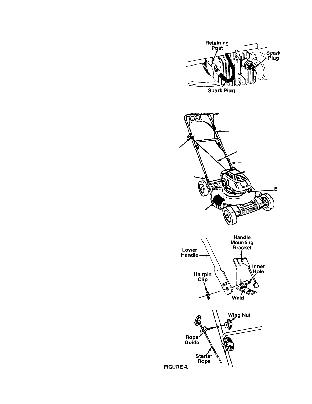
• Disconnect the spark plug wire from the spark plug.
Ground the spark plug wire by attaching it to the
retaining post until ready to operate your mower.
See figures 1 and 2. (Spark plug wire is shown in
figure 1 without the rubber boot for clarity.)
• Remove any packing material which may be
between the upper and lower handies for shipping
purposes.
• Pull up and back on the upper handle to raise the
handle into the operating position. Make certain the
lower handle is seated securely into the handle
mounting brackets. Tighten the hand knobs on
each side of the handle.
NOTE: Your mower is shipped with the handle in the
higher height position. If you wish to lower the height of
the handle, refer to the Adjustment Section at this time.
• Using a pair of pliers, remove hairpin clips from the
outer hole in weld pins on handle mounting brackets.
Place hairpin clips in the inner hole. See figure 3.
• The rope guide and wing nut are attached to the
starter rope, on top of the engine. Remove the wing
nut from rope guide. Remove the rope guide from
the starter rope.
• With the spark plug wire disconnected and ground
ed, hold the blade control handle against the upper
handle, and pull the starter rope out of the engine.
Hold the rope guide as shown so the opening in the
rope guide is toward the front of mower. Slip the
rope guide around the starter rope and into the right
side of upper handle using the hole shown. Secure
using the wing nut. See figure 4.
• Make certain all nuts and bolts are tightened
securely. Also, be certain to reconnect the spark
plug wire before starting the mower.
FIGURE 1.
Guide
FIGURE 2.
FIGURES.
Rope
Handle
Mounting
Bracket
Wire
Blade Control
Handle
Upper
Handle
Starter
Rope
Lower
Handie
Spark Plug
Wire and
oot
Mulching
Plug
Pin
Page 7
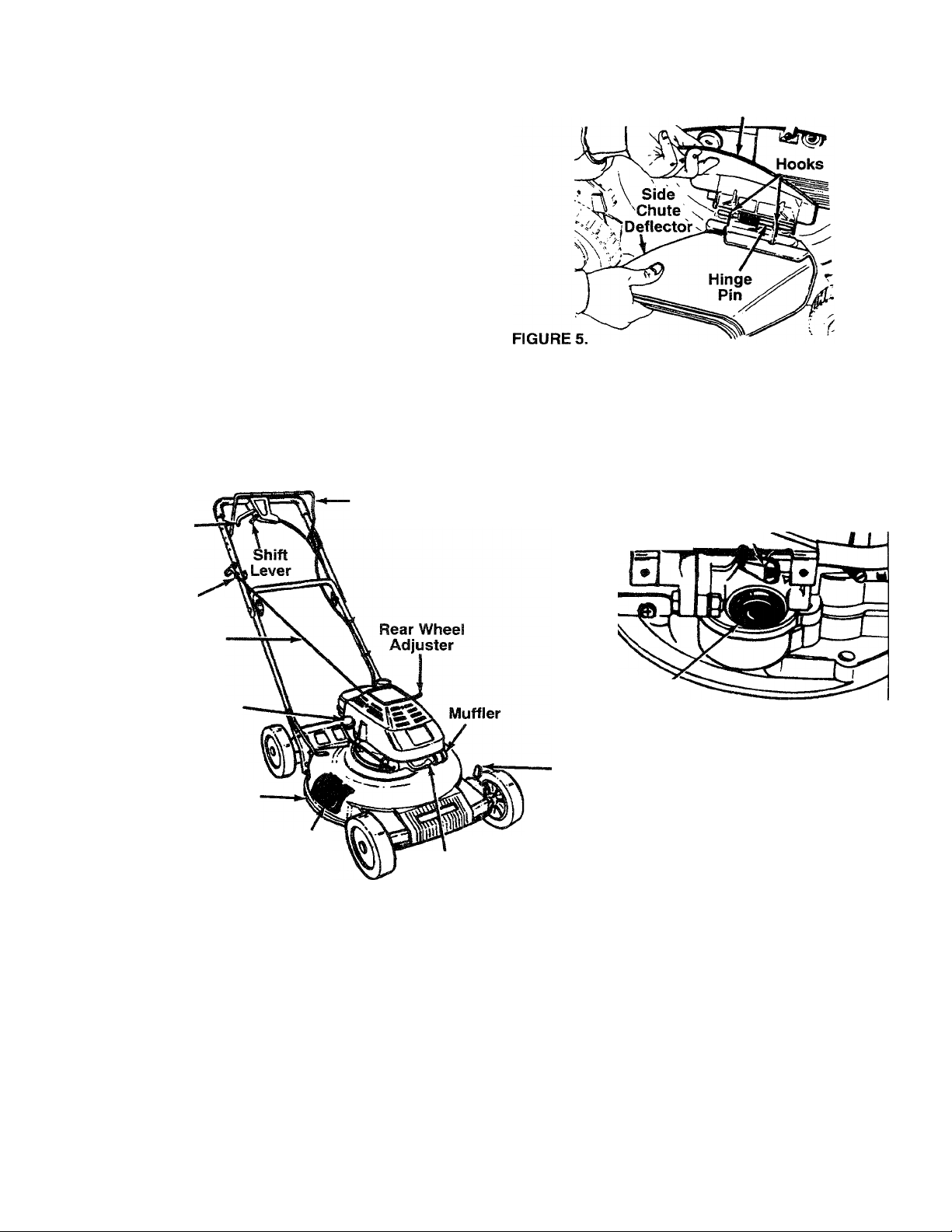
Your mower has been shipped as a mulcher. To dis
charge grass to the side, proceed as follows.
• To convert your mower from a muicher to a
side discharge mower, lift the mulching plug. See
Mulching
Plug
figure 5. Slide the two hooks on the side discharge
deflector under the hinge pin on the mulching plug
assembly. Lower the mulching plug.
OPERATION
KNOW YOUR LAWN MOWER
READ THIS OWNER’S MANUAL AND SAFETY RULES BEFORE OPERATING YOUR LAWN MOWER.
Oompare the illustrations with your lawn mower to familiarize yourself with the location of various controls and
adjustments. Save this manual for future reference.
Drive Clutch
Lever
Rope
Guide
Starter Rope
Oil Fill and Dipstick
FIGURE 6.
Deck
Mulching
Plug
-Blade Control
Handle
MEETS CPSC
Spark Plug
Wire and Boot
BLADE
SAFETY REQUIREMENTS
Primer
LEFT SIDE OF MOWER
Front
Wheel
Adjuster
Engine
Speed Control
Lever
Sears Walk-Behind Lawn Mowers conform to the safety standards of the American National Standards Institute,
and the U.S. Consumer Product Safety Commission. The blade turns when the engine is running.
BLADE CONTROL HANDLE—must be held down to
the handle to start and run the engine. Release to
stop the engine.
STARTER ROPE—used for starting the engine.
PRIMER—pumps additional fuel from the carburetor
to the cylinder for use when starting a cold engine.
ENGINE SPEED CONTROL LEVER—permits selec
tion of fast or slow engine speed.
DRIVE CLUTCH CONTROL—must be held against
the handle to engage the wheel drive. Release the
drive clutch control to stop the wheels from driving.
SHIFT LEVER—is used to select one of six operating
speeds for the mower.
Page 8

OPERATION
BEFORE USING YOUR LAWN MOWER, AGAIN REFER TO THE “SAFETY RULES" AS SHOWN ON PAGE 2
OF THIS MANUAL. ALWAYS BE CAREFUL.
The operation of any lawn mower can result in foreign objects being thrown into the
eyes, which can result in severe eye damage. Always wear safety glasses or eye
shields before starting power tool operation or while performing any adjustments or
repairs. We recommend Wide Vision Safety Mask for over spectacles or standard
glasses available at Sears Retail or Catalog Stores.
HOW TO USE YOUR MOWER
TO STOP ENGINE
Release blade control handle to stop engine.
Disconnect the spark plug wire and move it away from
the spark plug to prevent accidental starting while
equipment is unattended.
ADJUST CUTTING HEIGHT
The height adjuster levers for the wheels are located
on the left side of the deck. See figure 6, The levers
may be placed in one of nine cutting height positions.
Both levers should always be set to the same posi
tion.
• Raise wheels for low cut and lower wheels for high
ENGINE SPEED CONTROL
• To change cutting height, move adjuster levers
The engine speed is ccntroiied by a iever (red knob)
located on the left side of the engine. The “Hi’’ posi
tion is for starting engine, normal cutting and best pertormance. The "LOW’’ position is for light cutting, trim
ming and fuel economy.
• Adjust cutting height to suit your requirements.
BLADE CONTROL HANDLE
Your mower has a control handle which requires the
operator to be behind the handle to start and am the
mower, When the operator releases the control han
dle, the engine will stop and an internal brake helps
the blade to stop quickly.
When the operator leaves the operating position to
change the cutting height, pick up sticks or other
objects in the way, the engine vrill stop automatically
when the control handle is released.
BEFORE STARTING ENGINE
OIL
A 20 ounce bottle of SAE 30 oil is included with your
new lawn mower.
DRIVE CLUTCH CONTROL LEVER
To engage the wheel drive, squeeze the drive clutch
control lever against the handle. Releasing the drive
clutch control iever stops the wheels from driving.
Only use high quality detergent oil rated with API
service classification SQ or SH. Select the oil’s
viscosity grade according to your expected operating
temperature.
Release the drive clutch contrci iever to slow down
when negotiating an obstacle, making a turn or stop
colder 32T
ping.
cut.
toward wheels. Move wheels up or down to suit
your requirements. Be sure both levers are in the
same setting.
Refer to the "Mulching or Mowing Tips" on page 10.
(The height adjusters may seem hard to move when
new. They will operate easier after some use.)
Warmer
SHIFT LEVER
The six speed shift lever is located below the drive
clutch control lever. Position 1 is the slowest speed;
position 6 is the fastest. Release the drive clutch
control lever when changing speeds.
IMPORTANT; Move the shift lever ONLY when the
engine is running. Shifting the speeds with the
engine off can cause damage to the unit.
5W30
SAE 30
NOTE; Although mu It ¡-viscosity oil (SW30, 10W30,
etc.) Improve starting in cold weather, these multi
viscosity oils will result in increased oil consumption
when used above 32®F. Check your oil level more
frequently to avoid possible engine damage from
running low on oil.
Page 9

OPERATION
• Place unit so engine is in a level position.
• Remove oil fill cap and dipstick assembly. Pour oil
slowly until oil level is to the FULL mark on dipstick.
Crankcase capacity is approximately 1-1/4 pints
(20 ounces). DO NOT OVERFILL.
NOTE: Crankcase oil should be changed after first
two (2) hours of operation and every twenty-five (25)
hours thereafter. Refer to ENGINE LUBRICATION
section.
• Replace oil fill cap and dipstick. Tighten cap securely.
GAS
• Fill gas tank with about one (1) quart of clean,
fresh, lead-free grade automotive gasoline. Low-
lead or regular gasoline is an acceptable substitute.
DO NOT use Ethyl or high octane gasoline. Be cer
tain container is clean and free from rust or foreign
particles. Never use gasoline that may be stale
from long periods of storage in the container.
WARNING: EXPERIENCE INDICATES THAT ALCO
HOL BLENDED FUELS (CALLED GASOHOL OR
USING ETHANOL OR METHANOL) CAN ATTRACT
MOISTURE WHICH LEADS TO SEPARATION AND
FORMATION OF ACIDS DURING STORAGE.
ACIDIC GAS CAN DAMAGE THE FUEL SYSTEM
OF AN ENGINE WHILE IN STORAGE. TO AVOID
ENGINE PROBLEMS, THE FUEL SYSTEM
SHOULD BE EMPTIED BEFORE STORAGE FOR
30 DAYS OR LONGER. USE FRESH FUEL NEXT
SEASON. SEE “STORAGE” SECTION FOR ADDI
TIONAL INFORMATION.
NEVER USE ENGINE OR CARBURETOR CLEAN
ER PRODUCTS IN THE FUEL TANK OR PERMA
NENT DAMAGE MAY OCCUR.
NOTE: The drive cable has been adjusted at the fac
tory with the unit in sixth speed. If the drive slips when
mower is operated in first speed, tighten the cable by
moving the adjustment wheel away from the operator
slightly. ALWAYS MAKE CERTAIN THE MOWER
DOES NOT DRIVE WITH THE DRIVE CLUTCH
CONTROL LEVER RELEASED. Refer to “Drive
Clutch Adjustment” for further information.
• Connect spark plug wire to spark plug. Make cer
• Press primer button as follows (cold starts only).
• Set engine speed control to “HI” speed.
tain the metal cap on the end of the spark plug wire
(inside the rubber boot) is fastened securely over the
metal tip on the spark plug.
For each initial start, push primer button five times
prior to starter operation. See figure 7. Use sharp
pushes, wait between each push. Repeat the
above for each starter operation as necessary. Do
not use primer for warm engine restarts.
TO START ENGINE
WARNING: WHEN STARTING THE UNIT
FOR THE FIRST TIME, PLACE MOWER IN
A
FIRST SPEED (SLOW) POSITION. FACE
THE MOWER AGAINST A SOUD OBJECT
SUCH AS A WALL, FENCE, ETC. START
THE UNIT, AND IF IT SHOWS ANY SIGNS
OF MOTION WITH THE DRIVE CLUTCH
CONTROL DISENGAGED, SHUT THE
ENGINE OFF IMMEDIATELY. ADJUST THE
DRIVE CLUTCH CONTROL AS INSTRUCT
ED IN THE ADJUSTMENT SECTION.
FIGURE 7.
• Hold blade control handle against upper handle.
See figure 8. Grasp starter handle and pull rope out
slowly until engine reaches start of compression
cycle (rope will pull slightly harder at this point). Let
the rope rewind slowly.
• Pull rope with a rapid, continuous, full arm stroke.
Keep a firm grip on start handle. Let rope rewind
slowly. Do not let starter handle snap back against
starter.
• If after three pulls the engine fails to start, push
primer five times, then pull starter rope again.
Page 10

Starter
Handle
Blade Control
FIGURE 8.
Handle
MULCHING OR MOWING TIPS
• For best results in normal and heavy mowing,
always run engine in “HI" speed position. “LOW”
speed is only for light cutting, trimming and fuel
economy.
• The grass condition at the time of mowing deter
mines the proper mower cutting height setting for
best lawn appearance. For a healthy lawn, always
cut one-third or less of the total length of the grass
at any one cutting.
• Under certain conditions, such as very tall grass, it
may be necessary to raise the height of cut to
reduce pushing effort and to keep from overloading
the engine and leaving clumps of grass clippings.
• For extremely heavy cutting, use a slow ground
speed, and reduce the width of cut.
• Under heavy conditions cross cut for additional
mulching of surface debris.
CUSTOMER RESPONSIBILITIES
GENERAL RECOMMENDATIONS
• In order to maintain the warranty on your mower,
the customer is expected to perform the mainte
nance as outlined below.
MAINTENANCE SCHEDULE
SERVICE RECORD
Fill in dates as you
complete regular service
Check Engine Oil
Lubricate Mower V
Blade Care
Change Engine Oil
SCHEDULE SERVICE DATES
After
First
Every
Use
Two
Hours
V
Every
25
Hours
V
yf
Once a year you should replace the spark plug, air
filter, and check blade for wear. A new spark plug
and air filter assures proper air-fuel mixture and
helps your engine run better and last longer.
Spark Plug Replaced
Air Filter Replaced
Cleaning
VCHECK
y/
yf
V
10
Page 11

CUSTOMER RESPONSIBILITIES
LUBRICATION
ENGINE OIL RECOMMENDATIONS
• Use a block of wood between blade and mower
A 20 ounce bottle of SAE 30 oil is included with your
new lawn mower.
Only use high quality detergent oil rated with API ser
• Remove blade bolt by turning counterclockwise.
vice classification SG or SH. Select the oil’s viscosity
grade according to your expected operating tempera
ture.
Colder
32°F
-► Warmer
TO REPLACE BLADE (See Figure 9):
• Put blade adapter on engine crankshaft.
• Fit blade in adapter. Be sure trailing edge of blade
• Assemble bolts, washers, and nuts in the exact
5W30
SAE 30
• Use block of wood to hold blade and tighten bolt
NOTE: Although multi-viscosity oil (5E30, 10W30,
etc.) improves starting in cold weather, these multi
viscosity oils will result in increased oil consumption
when used above 32° F. Check your oil level more
frequently to avoid possible engine damage from run
ning low on oil.
IMPORTANT: THE BOLT USED TO SECURE THE
BLADE TO ENGINE IS SPECIALLY HEAT-TREATED.
WHEELS
DO NOT oil or grease the wheel bearings. Viscous
lubricants will attract dust and dirt that will shorten the
life of the self-lubricating wheel bearings. If you feel
the wheels must be lubricated, use only a dry, silicone
type lubricant sparingly.
WHEEL ADJUSTERS
A
Use only a Sears authorized replacement blade to get
the best cutting results.
For easy operation, lubricate the wheel adjusters at
least once a season with light oil.
BRAKE SPRING BRACKET
Spray a light oil lubricant on the brake spring bracket,
located on the right rear corner of the engine, at least
once a season.
TRANSMISSION
The transmission is pre-lubhcated and sealed at the
factory. It does not require checking. If disassembled
for any reason, fill with 2 ounces of Alvania grease,
part number 737-0168.
deck to prevent blade from turning when bolt is
removed. Protect your hands with gloves and/or
wrap blade with heavy cloth.
Use a 9/16" box or open-end wrench.
is up towards engine.
order of removal.
clockwise. The recommended torque for the center
is 450-600 in. lbs. The recommended torque for the
blade adapter bolts is 200-350 in. lbs.Torque
wrenches are available at most Sears stores and
through the catalog.
DO NOT SUBSTITUTE (SEE REPAIR PARTS).
CAUTION: A LOOSE BLADE CAN BE
DANGEROUS AND MAY MAKE THE
ENGINE HARD TO START.
MOWER
BLADE CARE
Your mower will work better with a sharp blade.
CAUTION: DISCONNECT SPARK PLUG
WIRE FROM SPARK PLUG AND PLACE
A
TO REMOVE BLADE (See Figure 9):
• Turn mower on its side. Make sure air filter and
carburetor are up.
WIRE WHERE IT CANNOT COME IN CON
TACT WITH THE SPARK PLUG.
FIGURE 9.
NOTE: We do not recommend sharpening the
blade—but if you do, be sure blade is balanced.
TO SHARPEN BLADE
• The blade can be sharpened with a file or on a
grinding wheel. Do not attempt to sharpen while on
the mower.
• Care should be taken to keep the blade balanced.
An unbalanced blade will cause excessive vibration
when running and eventual damage to mower and
engine.
11
Page 12

CUSTOMER RESPONSIBILITIES
• To check blade balance, drive a nail into a beam or
wall. Leave about one inch of the straight nail
exposed. Place center hole of blade over the head
of the nail. If blade is balanced, it should remain in
a horizontal position. If either end of the blade
moves downward, blade is not balanced. Sharpen
the heavy end until the blade Ls balanced.
ENGINE
ENGINE LUBRICATION
You must change the oil in the crankcase after the
first two (2) hours of operation and after each 25
hours of use thereafter. CHANGE THE OIL MORE
FREQUENTLY IF USED IN SANDY OR DUSTY
CONDITIONS.
TO DRAIN OIL
• Disconnect spark plug wire from spark plug and
place wire where it cannot come in contact with plug.
• Drain the gas tank,
• Remove the oil fill cap and dipstick. Turn and tip
the unit on Its side with the carburetor up, and drain
oil into a suitable container.
• Refill crankcase with oil. Refer to “ENGINE OIL
RECOMMENDATIONS" on previous page.
• Replace oil fill cap and dipstick. Tighten cap
securely.
SPARK PLUG
Change your spark plug each year to make your
engine start easier and run better. Set spark plug gap
at ,030 inch.
AIR FILTER
Your engine will not run properly and may be dam
aged by using a dirty air filter.
Replace the air filter every year, iTiore often if you mow
in very dusty, dirty conditions. Do not wash air filter.
TO CHANGE AIR FILTER {See Figure 10):
• Remove the air filter cover by turning counterclock
wise to the stop and pull away from collar.
• Remove filter from inside of cover,
CLEANING
* Clean the inside of the cover and the collar with a
clean Cloth to remove any dirt accumulation.
• Insert new filter into cover.
• Put air filter cover and filter into collar aligning the
tab with the slot.
* Push in on cover and turn clockwise to tighten.
Collar
Turn
Counter-
Clockwise
To Remove
Air Filter
Air Filter Cover
FIGURE 10.
WARNING: DISCONNECT SPARK PLUG
WIRE FROM SPARK PLUG AND PLACE
A
• Turn mower on its side with carburetor and air filter
• Clean the underside of your mower after each use
by scraping to remove build-up of grass clippings,
to accumulate, it will invite rust and corrosion, and
• Clean your mower and engine often to keep build
up of grass or debris from accumulating around
NOTE: We DO NOT recommend using a garden hose
to clean mower unless the electrical system, muffler,
air filter and carburetor are covered to keep water out.
Water in engine can result in shortening engine life.
WIRE WHERE IT CANNOT COME IN CON
TACT WITH THE SPARK PLUG.
up.
leaves, dirt or other matter. If this debris is allowed
may prevent proper mulching.
engine. A clogged engine runs hotter and shortens
engine life.
/ To Tighten
Turn Clockwise
SERVICE AND ADJUSTMENT
CUTTING HEIGHT ADJUSTMENT
Refer to “ADJUST CUTTING HEIGHT" In operation
section of manual,
HANDLE HEIGHT ADJUSTMENT
Your mower is shipped with the handle in the higher
height position. To lower the handle height, proceed
as follows.
12
• Remove the starter rope from the rope guide.
• Remove the upper handle by removing the hand
knobs and carriage bolts. Lay the upper handle out
of the way, being careful not to bend or kink the
cable.
• Remove the hairpin clips from the weld pins on the
handle brackets. Press outward on the sides of the
lower handle, and remove it from the mower.
Page 13

SERVICE AND ADJUSTMENT
Turn the lower handle around so the notch on the
bottom of the lower handle is facing forward as
shown In figure 11. Reassemble, placing the bot
tom holes In the handle over the weld pins in the
handle mounting bracket.
Reassemble the upper handle.
Place the hairpin clips in the Inner holes in the
weld pins and attach the starter rope as instructed
in the Assembly Section,
DRIVE CLUTCH ADJUSTIVIENT
The correct drive clutch adjustment varies with the
speed of the mower. The drive clutch adjustment may
be checked as follows. Without starting the engine,
engage the drive clutch control (squeeze control lever
against the handle) and pull the mower backward.
The wheels should lock. Then release the drive clutch
control and pull the mower backward, it should move
freely (or with only a small amount of resistance).
If the wheels lock up when pulled backward with the
drive clutch control released (engine off), or if mower
moves forward with the drive clutch control released
(engine running), turn the adjustment wheel, located
beneath the drive clutch control housing, toward the
operator to loosen the cable, See figure 12. Recheck
the adjustment as instructed above.
If the mower does not drive in low spaed, tighten the
cable by turning the adjustment wheel away from the
operator. Recheck the adjustment.
Periodic adjustment may also be necessary due to
normal stretch and wear on the belt. Adjustment may
be needed if the wheels seem to hesitate, but the
engine maintains the same speed. To tighten the
cable, move the adjustment wheel toward the right.
Always be certain to recheck the adjustment.
SIX SPEED SHIFT ADJUSTMENT
Periodic adjustment may be required due to normal
wear. Adjustment is needed if the shift lever cannot
be moved to all six positions.
• Loosen the nut which secures the adjustable cable
bracket, located on the left side of the engine. See
figure 13.
• Place the shift lever in high speed (6) position.
• Move the bracket to make certain it is loose. Then
slide It towards the rear of the unit as far as it will
go, so that the pulley halves (beneath the deck) are
against each other. Make certain the belt does not
interfere.
• Tighten the nut to secure the bracket in this
position.
Page 14

SERVICE AND ADJUSTMENT
CARBURETOR
Your carburetor has a non-adjustable fixed main jet
for mixture control. It has been completely adjusted at
the factory. If your engine does not operate properly
due to suspected carburetor problems, take your
mower to an authorized Sears Service Center for
repair and adjustment.
ENGINE SPEED
Your engine slow and fast speeds have been factory
set. Do not attempt to increase engine speed or it
may result in personal injury. If you believe that the
engine is running too fast or too slow, take your
mower to an authorized Sears Service Center for
repair and adjustment.
REAR TRAIL SHIELD
The rear trail shield, attached between the rear
wheels of your mower, is provided to minimize the
possibility that objects will be thrown out the rear of
the mower toward the operator.
If the shield becomes damaged, it should be replaced.
BELT REMDVAL AND REPLACEMENT
• Place shift lever in third speed.
• Disconnect the spark plug wire and ground it
against the engine.
• Drain the fuel tank or place a piece of plastic
beneath the cap to prevent gasoline leakage.
• Remove the transmission belt cover by removing
five self-tapping screws. See figure 14.
Self-Tapping
Screws
• Remove the inside belt cover by removing three
self-tapping screws. A 3/8" wrench is required.
• Roll the belt over the pulley half and remove from
around crankshaft.
• Remove the belt from between the idler pulley and
the belt guard on the idler pulley bracket. See figure
16.
Transmission
Belt
Cover
FIGURE 14
• Tip the mower on its side. Block securely.
• Remove the center bolt which secures the blade to
the crankshaft. See figure 15. Remove the blade
and blade adapter.
apping
Screws
14
FIGURE 16.
• Remove the belt from the transmission pulley.
• Assemble the new belt as follows.
• Push the idler pulley up out of the way as shown in
figure 16.
• Slide the belt in from the rear of the deck, and
place it around the transmission pulley.
• Release the idler pulley so it falls down into posi
tion. Slide the belt in between the idler pulley and
belt guard on the idler pulley bracket.
• Grease the crankshaft. Place belt between the two
pulley halves, and reassemble the blade adapter
and blade. Reassemble the inside belt cover.
• Reassemble the transmission belt cover.
Page 15

STORAGE
Your mower and engine should be prepared for off
season storage as follows:
MOWER
• Clean underside of mower housing (See “CLEAN
ING” in “Customer Responsibilities” section of
manual).
• Inspect and replace/sharpen blade, if required (See
“BLADE CARE” in “Customer Responsibilities”
section of manual).
• Lubricate as shown in “Customer Responsibilities”
section of manual.
HANDLE
• You can fold your mower’s handle for storage as
shown in figure 17. Remove the starter rope from
the rope guide. Loosen the two hand knobs on the
sides of the handle, and let the upper handle fold
down to the rear. Move the hairpin clips to the outer
hole in the weld pins on the handle mounting brack
ets. Refer to figure 3. Spread the sides of the lower
handle, and push it forward and down.
IMPORTANT: WHEN FOLDING HANDLE FOR
STORAGE OR TRANSPORTATION, BE CAREFUL
NOT TO BEND OR KINK THE CABLES.
To prevent engine damage if lawn mower is not used
for more than 30 days, proceed as follows.
IMPORTANT: IT IS IMPORTANT TO PREVENT
GUM DEPOSITS FROM FORMING IN ESSENTIAL
FUEL SYSTEM PARTS SUCH AS CARBURETOR,
FUEL FILTER, FUEL HOSE, OR TANK DURING
STORAGE. ALSO, FUEL (CALLED GASOHOL OR
USING ETHANOL OR METHANOL) CAN ATTRACT
MOISTURE WHICH LEADS TO SEPARATION AND
FORMATION OF ACID DURING STORAGE. ACIDIC
GAS CAN DAMAGE THE FUEL SYSTEM OF AN
ENGINE WHILE IN STORAGE.
NOTE: Fuel stabilizer is an acceptable alternative in
minimizing formation of fuel gum deposits during stor
age. Add stabilizer to gasoline in fuel tank in fuel tank
or storage container. Always follow mix ratio found on
stabilizer container. Run engine at least 10 minutes
after adding stabilizer to allow stabilizer to reach the
carburetor. Do not drain gas tank and carburetor if
using stabilizer.
• Drain the fuel tank. Start the engine, and let it run
until fuel lines and carburetor are empty.
• When storing the mower at the end of the season,
change the engine oil. Drain the oil after the engine
has been operated and is still warm, and refill the
crankcase with fresh oil.
• Lubricate the piston/cylinder area by first removing
the spark plug and squirting clean engine oil into
the spark plug hole. Then cover the spark plug hole
with a rag to absorb oil spray. Next, rotate the
engine by pulling the starter two or three times.
Finally, reinstall spark plug and attach spark plug
wire.
OTHER
• Do not store gasoline from one season to another.
FIGURE 17.
• To place the handle in the operating position, refer to
“Assembly” on page 6 of this manual.
• Replace your gasoline can if your can starts to rust.
• Do not store your mower under any plastic cover.
ENGINE
WARNING: NEVER STORE YOUR LAWN
MOWER INDOORS OR IN AN ENCLOSED,
A
POORLY VENTILATED AREA IF GASO
LINE REMAINS IN THE TANK. FUMES
MAY REACH AN OPEN FLAME, SPARK
OR PILOT LIGHT FROM A FURNACE,
WATER HEATER, CLOTHES DRYER,
CIGARETTE, ETC.
15
Rust and/or dirt in your gasoline can cause prob
lems.
Plastic cannot breathe which allows condensation
to form and cause the metal components of your
mower to rust.
Page 16

TROUBLE SHOOTING GUIDE
Trouble
Engine fails to start
Engine runs erratic
Engine overheats 1. Engine oil level low.
Occasional skip
(hesitates) at high speed
Idles poorly
Possible Cause(s)
1. Blade control handle disengaged.
2. Spark plug wire disconnected.
3. Throttle control lever not in starting position.
4. Fuel tank empty, or stale fuel.
5. Blocked fuel line.
6. Faulty spark plug.
7. Engine flooded.
1. Spark plug wire loose.
2. Blocked fuel line or stale fuel.
3. Vent in gas cap plugged.
4. Water or dirt in fuel system.
5. Dirty air cleaner.
2. Air flow restricted.
Spark plug gap too close.
1. Spark plug fouled, faulty or gap too wide.
2. Dirty air cleaner.
Corrective Action
1. Engage blade control handle.
2. Connect wire to spark plug.
3. Move throttle lever to starting position.
4. Fill tank with clean, fresh gasoline.
5. Clean fuel line.
6. Clean, adjust gap or replace.
7. Remove spark plug, dry the plug, and
crank engine with plug removed and
throttle in off position. Replace spark
plug, connect wire and resume starting
procedures.
1. Connect and tighten spark plug wire.
2. Clean fuel line: fill tank with clean,
fresh gasoline.
3. Clear vent.
4. Drain fuel tank. Refill with fresh fuel.
5. Clean air cleaner. See ’’Customer
Responsibilities” section of this manual.
1. Fill crankcase with proper oil.
2. Clean lawn mower engine.
Adjust gap to .030”.
1. Reset gap to .030” or replace spark plug.
2. Clean air cleaner. See ’’Customer
Responsibilities” section of this manual.
Excessive vibration 1. Cutting blade loose or unbalanced.
2. Bent cutting blade.
3. Bent engine crankshaft.
Mower will not
mulch grass
Uneven cut
Mower propels with
clutch disengaged
Mower will not propel
1. Engine speed too low.
2. Wet grass.
3. Excessively high grass.
4. Dull blade.
1. Wheels not positioned correctly.
2. Dull blade.
Drive clutch control adjustment needed.
1. Drive clutch control adjustment needed.
2. Wet grass.
1. Tighten blade and adapter.
Balance blade.
2. Replace blade.
3. Contact your SEARS Service Center.
1. Move throttle lever to FAST position.
2. Do not mow when grass is wet; wait until
later to cut.
3. Mow once at a high cutting height, then
mow again at desired height or make a
narrower cutting swath (1/2 width).
Do not cut off more than 1/3 of the total
length of the grass at any one cutting.
4. Sharpen or replace blade.
1. Place all four wheels in same
height position.
2. Sharpen or replace blade.
Adjust drive clutch control. See “Service
and Adjustment” section of this manual.
1. Adjust drive clutch control. See “Service
and Adjustment” section of this manual.
2. Do not mow when grass is wet; wait
until later to cut.
Note: For repairs beyond the minor adjustments listed above, contact your nearest SEARS Service Center.
16
Page 17

SEARS CRAFTSMAN 21" MULCHING ROTARY MOWER MODEL NO. 247.372900
Repair Parts
KEY
NO.
PART
NO.
1
710-1062
2
736-0329
717-0418A
3
4 713-0400
5
736-0336
6 741-0413
16500A Hex Bearing Cupt
7
736-0314
6
Hex Patch Bolt 1/4-20 x 1,25"t 33
L-Wash. 1/4" [.D.‘ 34
Upper Hsg. Halff 35
#48 Sprocket 7 T X 1/2 Pitcht
FI-Wash. 5/8" i.D. X ,030t
Hex Flange Brg. .631" I.D.f 38
Thrust Wash. .382" I.D. x 40
.70" O.O.f
741-0479
9
Thrust Bearing .375" I.D. x
,812"O.D.t
11
717-1216
748-0208A
12
721-0212
13
756-0330A
15
736-0270
ie
17 712-0351
18
738-0440
736-0344
19
20
738-0826
21
756-0558
741-0556
22
17052A idler Brk’t. Ass'y-
24
712-0138
25
732-0357
26
717-0419A
27
741-0415
28
29
717-0422A
741-0414
30
31
721-0213
738-0607A
32
11 Tooth Pinion Shaftf 45
Flange Bearingt 46
Oil Seaif
Fl-Pulley 5.06" O.D. 48 731-1281
Beli-Wasri. ,265" I.D. x .75"
Hex L-Nut 1/4-28 L.H. Thd.
Shid. Spacer .375" Dia. x .170 51
Fi-Wash. .390" I.D. x 1.0"
Shid. Bolt .375" Dia. x .40"
Fl-ldler Plastic 1.50" Dia.
Needle Brg. .375" x .31 58
Hex Patch L-Nut 1/4-2S Thd.
Extension Spring 1.12" Lg.
Lower Hsg. HaifT
Flange Bearing ,566 Dia.f
33 Tooth Helical Gearf 66
Flange Bearing .629 Dia.f
Oil Seal .625 Dia.f 70
Gear Sprocket Shaftf
DESCRIPTION
KEY
NO.
PART
NO.
736-0722
710-0436
736-0410
36 618-0055
37
738-0102
734-1512A
39 736-0105
710-1241
741-0492A
42
43
17733
782-0516
44
710-0653
720-0190
47
732-0639
710-0352
49
782-7558
50
710-0599
782-7554
54
56
710-1242
57
736-0242
731-0981A
746-0909
59
736-0222
60
712-0147
63
64
710-1003
710-0167
65
710-0603
67
712-3027
736-0329
DESCRIPTION
L-Wash. #10 I.D.f
Hex B-Tap Scr. #10 X .62"f
Hex Washer .26" x .88"
Transmission Comp.
Front Axle Bolt
Wheel Ass'y- Comp. 8x2"
Bell-Wash. .380" I.D. x .88
Hex Wash. Hd. Scr. 1/4 x i" Lg.
Block Bushing
Axle Ass'y,
Height Adj. Bracket
Hex TT-Tap Scr. 1/4-20 x .38"
Knob
Spring Lever
Plastic Front End
Hex B-Tap Scr. 1/4" X .38"
Belt Cover
Hex Wash. Hd. TT-Scr. 1/4-20
Transmission Belt Cover
Torx Truss Hd. Scr. 5/16 x .75"
Bell-Wash. .345" I.D. x .88"
Hub Cap
S,P. Cable
External L-Wash. 1/4" I.D.
Speed Nut #10-24 Thd.
Hex Tap Scr. #10-16 x .5" Lg.
Carr. Bolt 1/4-20 x .5" Lg.
Hex B-Tap Scr. 5/16-18 x .5"
Hex Flange L-Nut 1/4-20 Thd.
L-Wash. 1/4" I.D.*
tPart of Transmissior» Complete, Ref, No 36.
17
Page 18

SEARS CRAFTSMAN 21” MULCHING ROTARY MOWER MODEL NO. 247.372900
Repair Parts
18
Page 19

SEARS CRAFTSMAN 21"
Repair Parts
MULCHING ROTARY MOWER MODEL NO. 247.372900
720-0225
1
747-0824
2
710-1205
3
712-0279
4
5
750-0968
747-0855
6
7
736-0329
712-0287
8
736-0526
9
PART
NO.
DESCRIPTION
Grip (2 Req’d.)
Control Handle
Rope Guide
Wing Nut 1/4-20 Thd.
Spacer .885" I.D.
Belt Guard
L-Wash. ■1/4" I.D.*
Hex Nut 1/4-20 Thd.*
Wave Wash. .88" I.D. x 1,38"
KEY
NO.
O.D.
782-7007
10
731-0981A Hub Cap
11
12 710-1270
746-0883
13
749-0539B
14
731-1409
16
731-1501
17
714-0104 Internal Cotter Pin 5/l6" Dia.
18
20
747-0710
21
782-7006
22
732-0731
682-7002 Mulch Plug Ass'y- Comp,
23
Grass Catcher Bracket
Oval C-Sunk Mach. Scr. 75
Throttle Body
Upper Handle
Side Chute Deflector
Mulch Plug
Hinge Pin 748-0188B
Plug Adapter
Torsion Spring 84 741-04868
(Incl. Ref, 17, 20, 21,22)
24 736-0270
710-0167
2S
17070
26
1685S
27
28
782-7009
29
712-0324
714-0507 Cotter Pin 3/32" Dia. x .75"
30
736-0278
31
32
735-0639
656-0612
33
34
747-0382A
749-0928
35
143.955000
36
Beil-Wash. .265" I.D. x ,75" O.D.
Carriage Bolt 1/4-20 x .5" Lg. 98
Adjustable Cable Bracket 99
Pawl Plate
Chute Stop Bracket 101
Hex L-Nut 1/4-20 Thd.
Fl-Wash. .328" I.D. X .68" 115 731-0905
Spark Plug Insulator 118 710-0841
Lower Pulley Half Ass’y.
Shift Rod
Lower Handle
Engine—Craftsman Model
143.955000 128
37
582-7514 Housing,Ass’y. 129
731-1137
38
40
746-0706
42 682-7513
710-0653 Hex Hd. Tap Scr. 1/4-20 x ,38" 136
43
Flanged Bushing
6-Spd. Cable
Chain—/ofle Ass'y.
Lg.
44 736-0270
45
710-0351
712-0296
47
713-0361
46
BelWash. 1/4" I.D.
Truss Mach. B-Tap Scr, #10 x ,5"
Hex Patch L-Nut 3/8-24 Thd.
#48 Chain .500" Pitch x 38
Links
720-0241 Hand Knob
49
50
51
52
55
56
58
731-0906
731-1483
726-0240
748-0367
742-0721
736-0452
Cable Mounting Cap 153
Rear Flap 4.8" x 17.5" Lg.
Cable Tie
Blade Adapter
21" Mulching Blade
Bell-Wash, ,39" I.D. X 1.14"
O.D.
so
31
710-1257
748-0190
Hex Bolt 3/8-24 X 2.5" Lg.
Spacer ,513" I.D.
KEY
NO.
62
63
PART
NO.
782-7563
736-0451
64 682-3006A
65
682-3007A
66
710-0260
67 710-0603
68 710-0654A
69
712-0267
70
720-0230
71
732-0725
736-0242
73
74
750-0738
750-0624
77
712-0291
79 710-0653
80
738-0137
81
748-0381
734-151 OB
82
712-0414
86
95
746-071OA
96
754-0343
711-0313
710-1055
712-0241
100
736-0169
102
732-0027
114 731-0904
731-0620
119
710-1174
121
122
711-0805
712-0711
746-0737
748-0318
130
131
714-0115
134
741-0522
10822B
138
682-7506
140 710-0599
147
738-0864
741-0324
148
736-0160
149
152
710-0751
618-0055
154
16500A
155
736-0300
713-0397
163
165 731-0924
177
732-0627
178
16864
,
-----
770-8875K
DESCRIPTION
Bracket—Shift Plata
Saddle Washer ,32" I.D.
R.H. Handle Wheel Brki. Ass’y.
L.H. Handle Wheel Brkt. Ass'y.
Carriage Bolt S/16-18 x .62"*
Hex B-Tap Scr. 5/16-18
Hex TT-Tap Scr. 3/8-16
Hex Nut 5/16-18 Thd.*
Grip
Height Adj. Lever
Bell-Wash.5/16" I.D.
Spacer.383" I.D.
Shid. Spacer .5" Dia.
Hex L-Nut 1/4-20 Thd.
Hex Wash. Hd. Tap Scr, 1/4-20
X .38" Lg.
ShId. Scr, .342" Dia. x .268
Pawl—R.H.
Pawl
Wheel Ass'y, Comp.—Rear
Sleeve Bearing i/2" i.d.
Weld Top L-Nut 1/4-20 Thd.
S.P. Cable
"V"-Bett
Sleeve ,526" I.D.
Hex Bolt 3/8-24 X 1.0" Lg.
Hex Nut 3/8-24 Thd.
L-Wash. 3/8" I.D.
21" Deck Ass’y.
Upper Control Housing
Lower Control Housing
Fi-"C"-Sunk Hd. Tap Scr, #10 X
.75" Lg.
Control Lever
Curved Hd. Bolt 5/16-18 x 2" Lg.
Shid. Pin 1.43" Lg,
Hex Jam Nut 3/8-24 Thd.*
Control Cable—51"
Ratchet Wheel 1.62" O.D.
Cotter Pin 1/8" Dia. X 1"*
Hex Flange Bearing
Spring—Nylon
Chain Cover Ass’y.
Hex TT-Tap Scr. 1/4-20 X .50"
Rear Shaft Ass'y. 21.44" Lg.
Hex Flange Brg. ,506" I.D,
Fl-Wash. .531" I.D. x .930"
Hex Bolt 1/4-20 x .62" Lg.
(Grade 5)
Transmission Comp.
(See Breakdown)
Hex Bearing Cup
Fl-Wash. .385" I.D. X .87" O.D,
Gear Insert
6-Spd. Shift Lever
Shift Lever Spring
6-Spd. Rack Cable Brkt.
Owner's Manual
‘Common Hardware—May Be F’urchased Locally.
NOTE: Specifications subject to change without notice
or obligation,
19
Page 20

CRAFTSMAN 5 H.P. ENGINE MODEL NO. 143.955000
Repair Parts
347
[\^}^370D
ir^'^370A
216
20
Page 21

CRAFTSMAN 5 H.P. ENGINE MODEL NO. 143.955000
Repair Parts
KEY
NO.
1
2
6
7
12
12B
14
15
16
17
18
19
20
30
40
40
40
41
41
41
42
42
42
43
45
46
46
50
62
69
70
72
75
80
81
82
63
86
89
90
92
93
100
101
103
110
119
120
125
125
126
126
130
135
150
151
166
169
PART
NO.
36478A
26727
33734
36557
36558
34695
28277
30589
31383A
31335
650548
36281
32600
36215
36073
36074
36075
36070
36071
Cylinder (Incl. 2, 7,20 & 125)
Dowel Pin
Breather Element
Breather Body Ass’y- (Incl. 6 & 12)
Breather Covers Tube (Inci. 12B)
Breather Tube Elbow
Washer
Governor Rod (Incl, 14)
Governor Lever
Governor Lever Clamp
Screw, 8-32x5/16" 200
Extension Spring
Oi! Seal
Crankshaft
Piston, Pin S Ring Set (Std.)
Piston. Pin & Ring Set (.010" OS)
Piston, Pin S Ring Set (.020" OS)
Piston & Pin Ass'y- (Std.) (Inci. 43) 209
Piston & Pin Ass'y- {.010“ OS)
DESORIPDON
(Incl. 43)
36072
Piston & Pin Ass’y. (.020" OS)
(Incl. 43)
36076
36077
36078
20381
30963B
3261OA
27241
35992
29914
35261
34311D
36083
27897
30S74A
30S90A
30591
Ring Set (Std.)
Ring Sat (.010" OS)
Ring Set (.020" OS) 245
Piston Pin Retaining Ring
Connecting Rod Ass'y. (Incl, 46) 260
Connecting Rod Bolt
Valve Lifter
Camshaft (MGR)
Oil Pump Ass’y.
Mounting Flange Gasket
Mounting Flange (Incl. 72 thru 83)
Oil Drain Plug
Oil Seal
Governor Shaft 292
Washer
Governor Gear Ass’y. (Inci. 81)
30588A Governor Spool 305
650488
Screw, 1/4-20 X 1-1/4" 306
611004 Flywheel Key 307
611112
650815
650816
Flywheel 309
Belleville Washer 310
Flywheel Nut
34443A Solid State Ignition 347
810118
650814
34961
36477
36476
36471
36472
Spark Plug Cover 370A
Screw, Tor> T-15,10-24 x 1" 370B
Ground Wire 370D 35977
Cylinder Head Gasket 380
Cylinder Head
Exhaust Valve (Std.) (Incl. 151)
Exhaust Valve (1/32" OS)
(Incl. 151)
29314B
29315C
6021A
35395
35991
31673
35827
Intake Valve (Std.) (Incl. 151)
Intake Valve (1/32" OS) (Incl. 151}
Screw, 5/16-18 X 1-1/2"
Resistor Spark Plug (RJ19LM)
Valve Spring
Valve Spring Cap
Engine Shroud
27234A Valve Cover Gasket
KEY
NO.
172
174
178
182
184
185
186
189
191
195
PART
NO.
32755
30200
29752
6201 Screw. 1/4.28 X 7/8"
2S756
31384A
34358 Governor Link
650839
36559
610973 Terminal
35727
202
203
204
205
207
36482
31342
650549
650777
34336
30200
215
223
224
238
239
35511
650451
34690A
650932 Screw, 10-32 X 49/64"
34338
241 35797
35066
250
35065
35826
261
262
263A
275
277
285
287
30200
650831
35821
36473
650988
35000A
650926
290 34357
26460
300
301
35586
35355
35819A
34265
35499
650936
35822
313
34080
650698
36261
35167
632670
390 590702
(NOTE: This engine could have been built with
590637 starter. Refer to the design of the air
intake louvers
starter parts dc
400
36481
416 36085
417
650760
RPM Setting:
Low Speed: 2750-3050
High Speed: 3200-3400
DESCRIPTION
Valve Cover
Screw, 10-24x9/16"
Nut & Lock Washer, 1/4-28
Carburetor to Intake Pipe Gasket
Intake Pipe (Incl. 224)
Screw, 1/4-20 X 3/8"
S.E, Brake Bracket (Incl. 195)
Control Bracket (Incl. 202 thru
205}
Compression Spring
Compression Spring
Screw. 5.40x7/16"
Screw, 8-32 X 21/32"
Throttle Link
Screw, 10-24 x 9/16"
Control Knob
Screw, 1/4-20 X 1"
Intake Pipe Gasket
Air Cleaner Gasket
Air Cleaner Collar
Air Cleaner Fitter
Air Cleaner Cover
Blower Housing
Screw. 10-24 X 9/16"
Screw, 1/4-20 X 1/2"
Starter Grill
Muffler (Ind. 277)
Screw, 1/4-20 x 2-5/16"
Starter Cup
Screw, 8-32 X 21/64"
Fuel Line
Fuel Line Clamp
Fuel Tank (Incl. 292 & 301)
Fuel Cap
Oil Fill Tube
“0"-Ring
"0".Ring
Screw, 10-32 X13/32"
Dipstick
Spacer
Screw, 10-32 X 27/64"
Lubrication Decal
Control Decal
Caution Decal
Carburetor (Incl. 184)
Recoil Starter
for part identification. Individual
not interchange.)
Gasket Set (incl. Part Nos. 26756,
27234A, 33735, 34265, 34338,
34690A, 35261, 36477
Spark Arrestor Kit (incl. 417)
(Optional)
Screw, 8-32 X 3/8" (Optional)
21
Page 22

CRAFTSMAN 5 H.P. ENGINE MODEL NO. 143.955000
Repair Parts
PARTS LIST FOR CARBURETOR
KEY
NO.
—
16 631775
25 631867
27 631024
28 632019
29 631028
30
31
35
35A
40
44
48 531027
PART
NO.
632670
1 631615
2 631767
4 631184
5 631183
632504 Throttle Shutter
6
7 650506
Carburetor Comp.
Throttle Shaft & Lever Ass’yThrottle Return Spring
Dust Seal Washer (Throttle)
Dust Seal (Throttle)
Throttle & Choke Shutter Screw
description
Fuel Fitting
Float Bow!
Shaft. Float
Float
0-Ring, Float Bowl to Body
631021
Inlet Needle. Seat & Clip
(inci. No. 31)
631022
Spring Clip
632694 Primer Bulb/Retainer Ring
632647
632503
27110
Primer Bulb Filter
High Speed Bowl Nut
Bowl Nut Washer
Welch Plug, AtiTOSpheric Vent
'16
PARTS LIST FOR RECOIL STARTER
KEY
NO.
_—
1
11
PART
NO.
DESCRIPTION
590702 Recoil Starter
590599A
2
590600
3 590696
4
590601
5
590697
6
590698
7
590699
8 590700
Spring Pin (Incl. 4)
Washer
Retainer
Washer
Brake Spring
Starter Dog
Dog Spring
Pulley & Rewinc: Spring Ass'y.
590703 Starter Housing Ass’y.
(40 Degree Grommet)
12 590535
13 590701
PARTS LIST FOR RECOIL STARTER
KEY
—
PART
NO.
NO.
590637 Recoil Starter
1 590599A
2 590600
3
590615
4
590601
Starter Rope (98" x 9/64" Dia.)
Starter Handle
DESCRIPTION
Spring Pin (Ind, 4)
Washer
Retainer
Washer
5 590598 Brake Spring
6 590616
590617 Dog Spring
7
8 590618A
9
590619
10
590620 Spring Cover
11 590638
Starter Dog
Pulley Ass’y. (IpcI. 9 & 10)
Rewind Spring
Starter Housing Ass’y.
(40 Degree Grommet)
12
590536
13 590701
Starter Rope (98" x 9/64” Dia.)
Starter Handle
'i
22
Page 23

USE THIS PAGE AS A GUIDE TO DETERMINE SLOPES WHERE YOU MAY NOT OPERATE SAFELY.
1
■ SIGHT Al№ HOLD THIS LEVEL WITH A VERTICAL THEE
A POWER POLE
A CORNER OF A BUILLHNG
OR A FENCE POST
CD
CD
LLI
CO
---------
--
I *
..................
I
FVTWIfWnif I'Wiw'rrTTTrv* irrirt'TWTrT
--------
--
•••«
AC WARNING I
Do not mow on Inclines with a slope in excess of 15 degree {a rise of appimlmalely 2-1/2 feet every io feet). If
operating a walk-behlnd mower on such a slope, it is extrenu^y difficult to maintain your footing and you could
^Ip, resulting In serious Injury.
Of^rate WALK-BEHIND mowers across the face of slopes, never up and down ^opes.
Page 24

CRRFTSMRN
OWNER’S
MANUAL
MODEL NO.
247.372900
HOW TO ORDER
REPAIR PARTS
5.0 HORSEPOWER 21" POWER PROPELLED 6-SPEED “3-IN-1”
MULCHING ROTARY MOWER
Each lawn mower has its own model number. Each engine
has its own model number.
The model number for your lawn mower will be found on a
label attached to the lawn mower on the top rear of the
deck.
The model number for the engine will be found on the
blower housing of the engine adjacent to the spark plug.
All parts listed herein may be ordered through Sears,
Roebuck and Co. Service Centers and most Retail Stores.
WHEN ORDERING REPAIR PARTS, ALWAYS GIVE THE
FOLLOWING INFORMATION:
IF YOU NEED REPAIR
SERVICE OR PARTS:
REPAIR SERVICE
1-800-4-REPAIR
(1-800-473-7247)
ORDERING PARTS
1-800-FON-PART
(1-800-366-7278)
SEARS, ROEBUCK AND CO., Hoffman Estates, IL
770-8875K 1/95
* PRODUCT - “21 ■■ Mulching Rotary Mower”
* MODEL NUMBER - 247.372900
* ENGINE MODEL NUMBER-143.955000
* PART NUMBER
* PART DESCRIPTION
Your Sears merchandise has added value when you con
sider that Sears has service units nationwide staffed with
Sears trained technicians...professional technicians specifi
cally trained on Sears products, having the parts, tools and
the equipment to insure that we meet our pledge to you...we
service what we sell.
60179 U.S.A.
Printed in U.S.A.
 Loading...