

Page 1
OWNER’S
MANUAL
MODEL NO.
247.370320
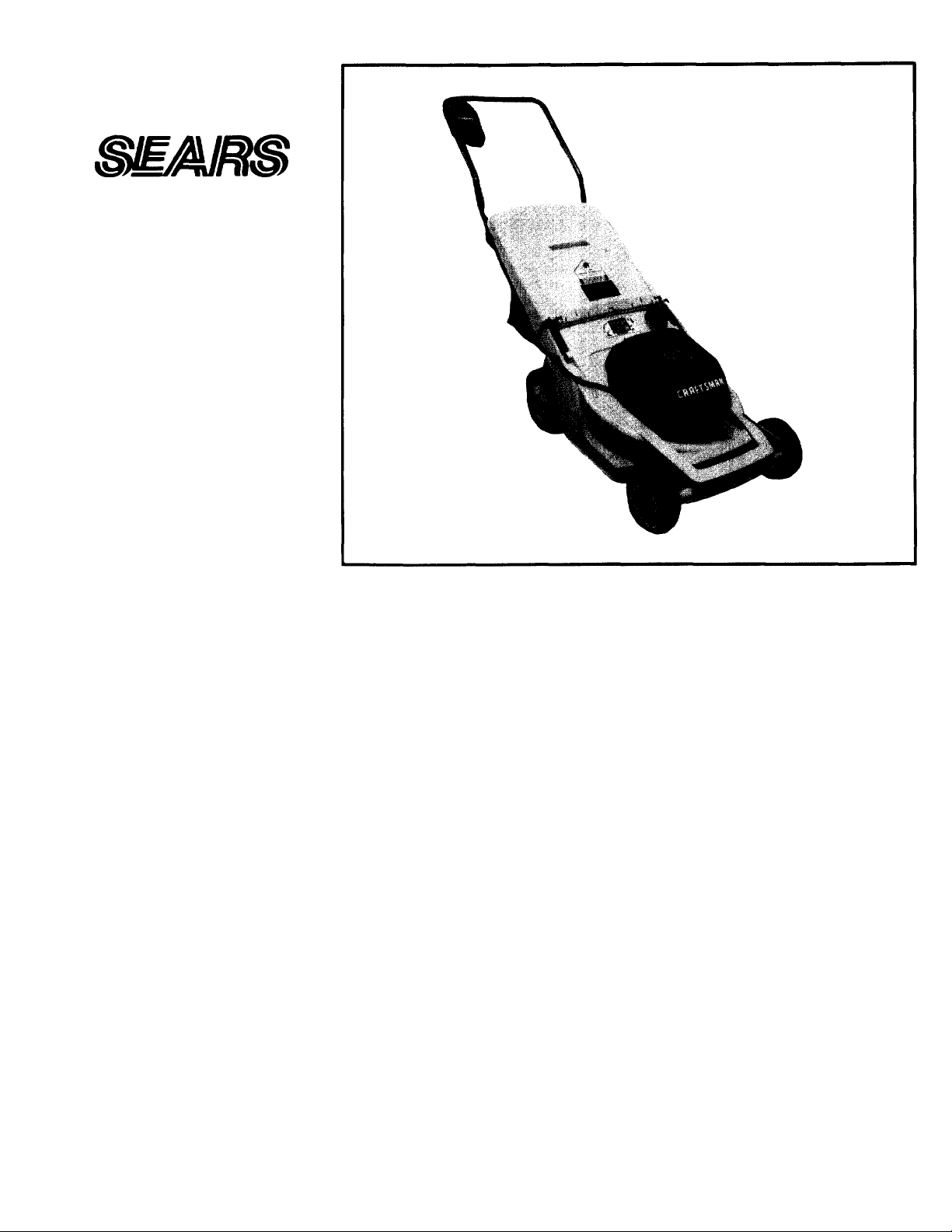
CRRFTSMRN
Caution:
Read and Follow
All Safety Rules
and Instructions
Before Operating
This Equipment
110V 12AMP ELECTRIC
DOUBLE INSULATED
18'' REAR DISCHARGE
ROTARY LAWN MOWER
Assembly
Operation
Maintenance
Service and Adjustment
Repair Parts
SEARS, ROEBUCK AND CO., Chicago, IL 60684 U.S.A.
Page 2
IMPORTANT
THIS SYMBOL POINTS OUT IMPORTANT SAFETY INSTRUCTIONS WHICH, IF NOT FOLLOWED, COULD ENDANGER THE PERSONAL SAFETY
AND/OR PROPERTY OF YOURSELF AND OTHERS. READ AND FOLLOW ALL INSTRUCTIONS IN THIS MANUAL BEFORE AHEMPTING
TO OPERATE YOUR ELECTRIC LAWN MOWER. FAILURE TO COMPLY WITH THESE INSTRUCTIONS MAY RESULT IN PERSONAL INJURY
A
WHEN YOU SEE THIS SYMBOL-
A HEED ITS WARNING.
RULES FOR SAFE OPERATION
A
A'
A-
DANGER: As with any type of power equipment, carelessness or error on the part of the operator can result in serious
A
TRAINING
Read this owner’s manual carefully in its entirety before attempting to assemble
or operate this machine. Be completely familiar with the controls and the
proper use of this machine before operating it. Keep this manual in a safe
place for future and regular reference and for ordering replacement parts.
Your rotary mower is a precision piece of power equipment, not a plaything.
Therefore, exercise extreme caution at all times.
Never allow children to operate a power mower. Only persons well acquainted
with these rules of safe operation should be allowed to use your mower.
No one should operate this unit while intoxicated or vdiile taking medication
that impairs the senses or reactions.
Keep the area of operation clear of all persons, particularly small children
and pets. Stop motor when they are in the vicinity of your mower. Although
the area of operation should be completely cleared of foreign objects, an
object may have been overlooked and could be accidently thrown by the mower
in any direction and cause serious personal injury to the operator or any others
allowed in the area.
PREPARATION
Thoroughly inspect the area where the equipment is to be used. Remove
all stones, sticks, wire, bones and other foreign objects which could be picked
up and thrown by the mower in any direction and cause serious personal
injury to the operator or any others allowed in the area.
Always wear safety glasses or eye shields during operation or while performing
an adjustment or repair, to protect eyes from foreign objects that may be
thrown from the machine in any direction.
Dress properly. Wear sturdy, rough-soled work shoes. Never operate a unit
in barefeet, sandals or sneakers. Do not wear loose clothing or jewelry. They
can be caught in moving parts. Use of rubber gloves and footwear is recom
mended when working outdoors.
Never attempt to make a wheel or cutting height adjustment while the motor
is running.
Mow only in daylight or in good artificial light.
Never operate the equipment in the rain or in damp wet locations. Always
be sure of your footing. A slip and fall can cause serious personal injury.
Keep a firm hold on the handle and walk, never run. Do not over-reach—
keep footing and balance at all times.
Warning—To prevent electric shock hazard, use only with an extension cord
suitable for outdoor use. Use only UL approved outdoor extension cords of
adequate gauge (minimum 16 gauge recommended) which accept the lawn
mower's plug.
Cord sets—Make sure your cord set is in good condition. When using a cord
set, be sure to use one heavy enough to carry the current your lawn mower
will draw. For lengths less than 50 feet. No. 16 AWG cord set should be
used. An undersized cord will cause a drop in line voltage resulting in loss
of power and overheating. (NOTE: Table below shows the correct size to use
depending on cord length and nameplate ampere rating. If in doubt, use the
next heavier gauge. The smaller the gauge number the heavier the cord.)
Your electric lawn mower was built to be operated according to the rules for safe operation in this manual.
injury. If you violate any of these rules, you may cause serious injury to yourself or others.
A'
Required Cord Gauge
Motor
Amp
Rating
10-12 16 16 14 12
If extension cord is damaged in any manner while plugged in, pull extension
cord from wall receptacle.
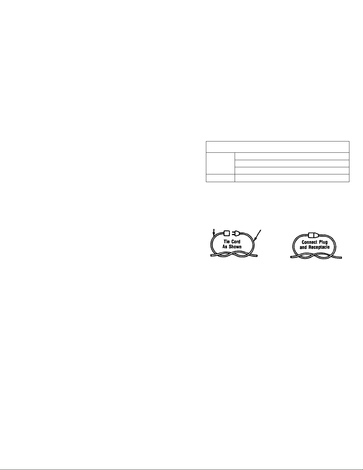
To prevent disconnection of extension cord from mower during operation,
be sure to use the cord restraint provided or make a knot as shown in the
illustration below.
Extension
Cord
Fuses—The mower should be operated on a 15 or 20 AMP circuit. If difficul
ty in starting is experienced with a standard 15 AMP fuse or circuit breaker,
contact your nearest authorized service location. Do not use a higher rated
fuse without consulting your power company.
For your safety, use the slope gauge included as part of this manual to measure
slopes before operating this unit on a sloped or hilly area. If the slope Is greater
than 15° as shown on the slope gauge, do not operate this unit on that area
or serious injury could result.
OPERATION
Avoid accidental starting. Do not pull plugged-in lawn mower with finger on
switch. Be sure switch is off when plugging in.
Do not abuse cord—never pull lawn mower by cord or yank it to disconnect
from receptacle. Keep cord from heat, oil, and sharp edges.
Do not put hands or feet near or under rotating parts. Keep clear of the
discharge opening at all times as the rotating blade can cause injury.
Stop the motor when you leave the mower and before crossing gravel drives,
walks or roads.
After striking a foreign object, shut off the motor, make absolutely sure the
blade and all moving parts have completely stopped, disconnect the power
cord to prevent accidental starting, then thoroughly inspect the mower for
any damage. Such damage must be repaired before restarting and operating
the mower.
If the equipment should start to vibrate abnormally, stop the motor and check
immediately for the cause. Vibration is generally a warning of trouble
Stop the motor, unplug the power cord, and wait for the blade and all;
ing parts to stop before cleaning, unclogging chute, removing grass catci,
repairing or inspecting the mower. The cutting blade continues to rotate tor
a few seconds after the motor is shut off.
Cord Length in Feel
25 50 100 150
Wire Gauge
Appliance
Cord
Page 3

SAFE OPERATION PRACTICES (Continued)
Do not force lawn mower. It will do the job better and safer at the rate for
which it was designed. Do not use lawn mower for any job except that for
which it is intended.
Mow across the face of slopes, never up-and-down. Never cut grass by pull
ing mower toward you. Exercise extreme caution when operating mower on
uneven terrain or changing direction on siopes. Do not mow excessively steep
slopes. Always be sure of your footing. A slip and fall can cause serious per
sonal injury.
Never operate mower without proper guards, plates or other safety protec
tive devices in place.
The blade/motor control on this mower is installed to minimize the risk
of blade contact injury and is required by federal regulations. Do not under
any circumstances attempt to defeat the function of the blade/motor control.
To avoid eiectric shock hazard, never push mower over cord. Do not mow
around the lawn in circles, /\lways travel back and forth across the lawn,
beginning at the point nearest the electric outiet to which the extension cord
is connected. This will keep the cord on the mowed area of the lawn and
out of the way.
Do not operate mower after it has been dropped or damaged in any manner.
Return mower to nearest authorized service location.
The use of accessory attachments not recommended by the mower manufac
turer may cause hazards.
Do not operate this mower with the chute door open, uniess the compiete
grass catcher or chute deflector is properly mounted on the mower.
MAINTENANCE AND STORAGE
Warning—Disconnect power cord from electrical outlet before performing any
maintenance or service on mower.
Check the blade and motor mounting bolts at frequent intervals for proper
A
tightness. Keep all nuts, bolts, and screws tight to be sure the equipment
is in safe working condition.
• Keep blade sharp.
• Use identical replacement blades only. Repair or replace damaged cord.
• To reduce fire hazard, keep the motor free of grass, leaves, or excessive
grease.
• Check the grass catcher bag frequently for wear or deterioration and replace
worn bags. For safety protection, replace only with new bag meeting original
equipment specifications.
• Store idle lawn mower indoors when not in use. Allow motor to cool before
storing In any enclosure. Lawn mower should be stored indoors in dry, high
or locked-up place, out of reach of children.
• Maintain lawn mower with care. Keep blade sharp and clean for best and
safest performance. Follow instructions for lubricating and changing ac
cessories.
DOUBLE INSULATED LAWN MOWER
DOUBLE INSULATION IS A CONCEPT IN SAFETY IN ELECTRIC LAWN MOWERS,
WHICH ELIMINATES THE NEED FOR THE USUAL THREE WIRE GROUNDED
POWER CORD AND GROUNDED SUPPLY SYSTEM. WHEREVER THERE IS ELEC
TRIC CURRENT IN THE MOWER, THERE ARE TWO COMPLETE SETS OF IN
SULATION TO PROTECT THE USER. ALL EXPOSED METAL PARTS ARE
ISOLATED FROM THE INTERNAL METAL MOTOR COMPONENTS WITH PRO
TECTING INSULATION.
IMPORTANT-SERVICING OF A LAWN MOWER WITH DOUBLE INSULATION
REQUIRES EXTREME CARE AND KNOWLEDGE OF THE SYSTEM AND SHOULD
BE PERFORMED ONLY BY A QUALIFIED SERVICE TECHNICIAN. FOR SERVICE
WE SUGGEST YOU RETURN THE LAWN MOWER TO YOUR NEAREST
AUTHORIZED SERVICE DEALER FOR REPAIR. ALWAYS USE ORIGINAL FAC
TORY REPLACEMENT PARTS WHEN SERVICING.
CONGRATULATIONS on your purchase of a Sears
Craftsman Lawn Mower. It has been designed, engineered
and manufactured to give you the best possible dependability
and performance.
Should you experience any problem you cannot easily
remedy, please contact your nearest Sears Service
Center/Department. We have competent, well-trained tech
nicians and the proper tools to service or repair this unit.
Please read and retain this manual. The instructions will
enable you to assemble and maintain your lawn mower
properly. Always observe the “SAFETY RULES.”
MODEL
NUMBER
SERIAL
NUMBER
DATE OF
PURCHASE
THE MODEL AND SERIAL NUMBERS WILL BE FOUND
ON A LABEL ATTACHED TO THE REAR OF THE DECK.
YOU SHOULD RECORD BOTH SERIAL NUMBER AND
DATE OF PURCHASE AND KEEP IN A SAFE PLACE
FOR FUTURE REFERENCE.
247.370320
PRODUCT SPECIFICATIONS
VOLTAGE;
AMPERAGE: 12
Hz;
BLADE NUT TORQUE:
110 - 120 AC
60
30-35 ft. lbs.
MAINTENANCE AGREEMENT
A Sears Maintenance Agreement is available on this
product. Contact your nearest Sears store for details.
CUSTOMER
RESPONSIBILITiES
• Read and observe the safety rules.
• Follow a regular schedule in maintaining, caring for
and using your lawn mower.
• Follow the instructions under “Maintenance” and
"Storage” sections of this Owner’s Manual.
________
Page 4

TABLE OF CONTENTS
SAFETY RULES......................................................................2
PRODUCT SPECIFICATIONS
CUSTOMER RESPONSIBILITIES
INDEX.......................................................................................4
WARRANTY ............................................................................4
CONTENTS OF HARDWARE PACK
ASSEMBLY.........................................................................5, 6
OPERATION.........................................................................7-9
Adjustments:
Cutting Height
Assembly:
Chute Deflector
Handle
................................................
Grass Catcher
Blade:
Balancing.........................................10
Replacement
Sharpening
Cleaning
Controls:
Cord Restraint
Customer Responsibilities
Cutting Heights......................................8
..............................................
Motor/Blade Control
Height Adjustment Knob
...................................
.................................
...................................
B
...................................
.....................................
C
....................................
................................................
..........................................
......................................
8
6
6
6
10
10
10
........................
..................
...................
8
8
5-8
3
Hardware Pack Contents......................5
Handle Storage
Lubrication:
Motor
...............................................
Wheels.............................................11
Maintenance:
Agreement
Blade Care/Replacement ... .10
Cleaning...........................................10
Lubrication......................................11
Operating Mower................................7-9
Repair/Replacement Parts. . .14-18
Responsibilities, Customer
MAINTENANCE ....................................................................V
3
3
5
SERVICE AND ADJUSTMENT
STORAGE.............................................................................11
SERVICE RECOMMENDATIONS
TROUBLE SHOOTING
SLOPE GAUGE ....................................................................13
REPAIR PARTS
PARTS ORDERING/SERVICE
INDEX
H
...................................
L
M
.........................................
O
R
.................
............................................
.......................................
..........................................................
...............................................................
.........................
11
11
Safety Rules
Service and Adjustments:
Cutting Height
Rear Trail Shield
Service Recommendations.
Specifications.............................
Starting the Motor/Blade ..
Stopping the Motor/Blade..
3
3
Storage........................................
Table of Contents
Trouble Shooting Guide
Warranty...............................
Wheels:
Adjusting Height ....
Lubrication
...............................
........................
................
......................
BACK PAGE
....................
W
10
11
12
14-18
. .8
.10
.11
. .3
. .9
, .9
.11
. .4
.12
.L
11
Extension Cord
.........................
2, 8, 11
WARRANTY
ONE YEAR LIMITED WARRANTY ON CRAFTSMAN LAWN MOWER
For one year from the date of purchase, when this Craftsman Lawn Mower is maintained and lubricated accord
ing to the instructions in the owner’s manual. Sears will repair, free of charge, any defect in material and
workmanship.
If this Craftsman Lawn Mower is used for commercial or rental purposes, this warranty applies for only 90 days
from the date of purchase.
This warranty does not cover:
• Expendable items which become worn during normal use, such as mower blades or blade adapters.
• Repairs necessary because of operator abuse or negligence, including bent motor shafts and the failure
to maintain the equipment according to the instructions contained in the owner's manual.
WARRANTY SERVICE IS AVAILABLE BY RETURNING THE CRAFTSMAN LAWN MOWER TO THE NEAREST
SEARS SERVICE CENTER/DEPARTMENT IN THE UNITED STATES. THIS WARRANTY APPLIES ONLY
WHILE THIS PRODUCT IS IN USE IN THE UNITED STATES.
This warranty gives you specific legal rights, and you may also have other rights which may vary from state
to state.
SEARS, ROEBUCK AND CO. Department 731CR-W Sears Tower, Chicago, IL 60684
Page 5
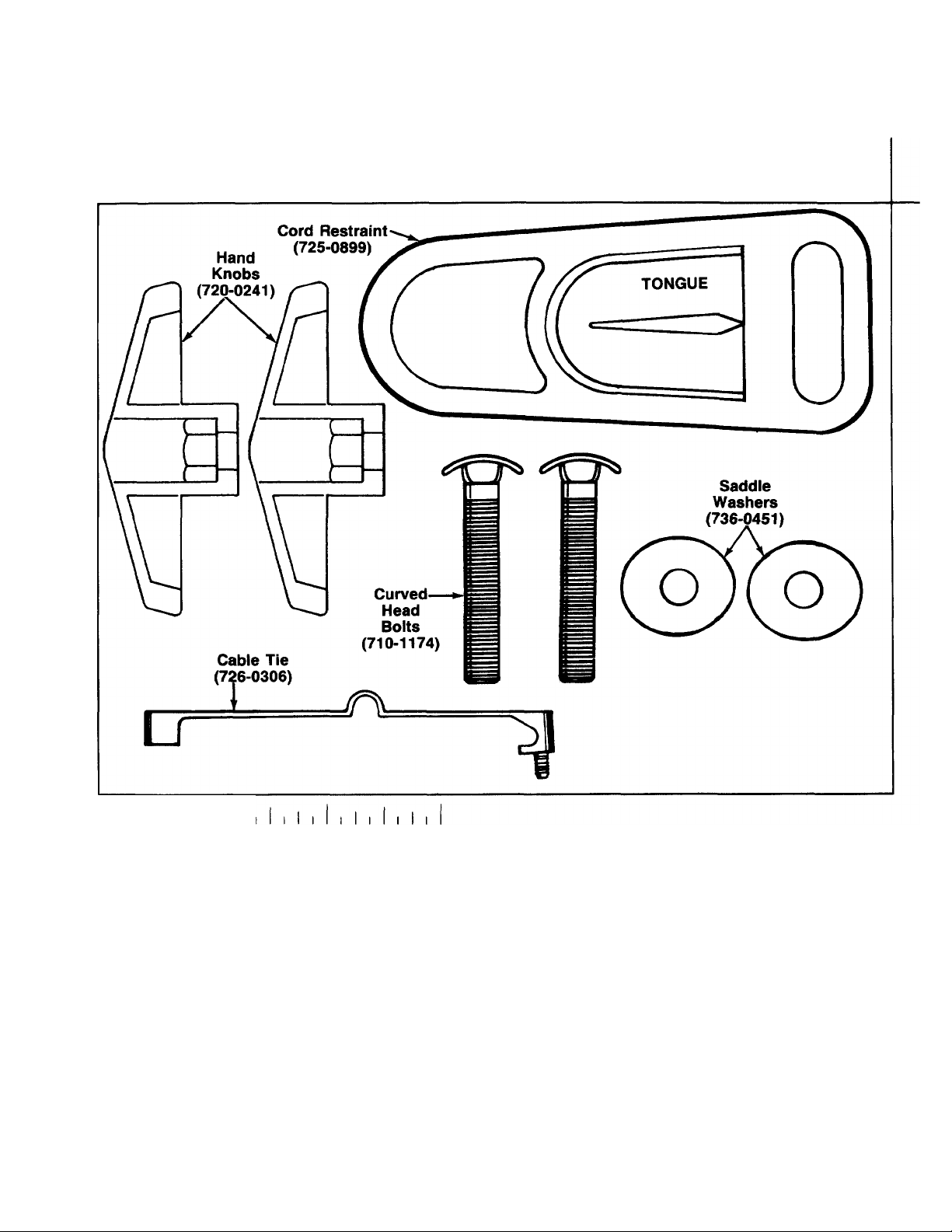
CONTENTS OF HARDWARE PACK
(Hardware pack may contain extra items which are not used on your unit. Part numbers are shown in
parentheses.)
I I I I I I I I I I I
0
INCHES
ASSEMBLY INSTRUCTIONS
NOTE: Reference to right or left hand side of the
mower is observed from behind the mower in the
operating position.
Read this manual in its entirety before attempting to
assemble or operate the lawn mower.
For shipping purposes, the lawn mower has been
assembled at the factory, except for the upper handle.
The necessary hardware is found in the hardware pack.
Before assembling or operating the mower, check for
damage and/or missing parts. Do not operate this
mower until the following steps have been completed.
UNPACKING
• Remove the lawn mower from the carton by open
ing the top flaps and removing the carton inserts,
grass catcher, chute deflector and hardware pack.
• Cut along the corners on one end of the carton, and
lay the end of the carton down flat.
• Roll mower out of carton. Make certain all parts and
literature have been removed from the carton before
the carton is discarded.
NOTE: The control cord is attached to both the upper
handle and the motor. Use care in removing the mower
from the carton.
Page 6
Control
Cord
Hand
Knob
Cord Restraint
Tongue
Saddle Washer
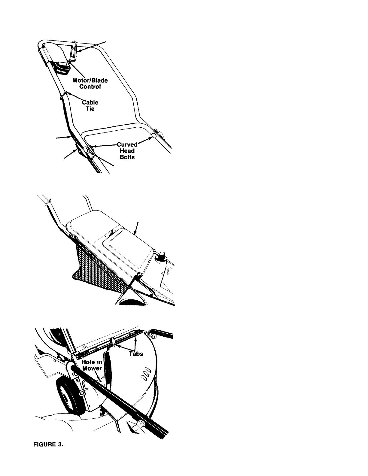
ATTACHING THE HANDLE
• Lay the upper handle to the right side of the mower
so the control cord is out of the way.
• Pull up and back on the lower handle until it locks
into operating position.
• Attach the upper handle as follows.
a. Slide cord restraint onto the top of upper handle,
so the tongue of the cord restraint is away from
----------
the motor/blade control as shown in figure 1.
Place the upper handle position over lower han
b.
dle. Make certain the control cord is routed to the
outside and below lower handle as shown in
figure 1.
Secure the handles using the curved head bolts,
c.
saddle washers and hand knobs as shown.
Tighten securely.
• Attach the control cord to the upper handle at the
position shown in figure 1, using the cable tie
provided.
FIGURE 1.
FIGURE 2.
Chute
Door
ATTACHING THE GRASS CATCHER OR CHUTE DEFLECTOR
Your mower is equipped with a grass catcher to bag
grass clippings, and a chute deflector to allow clippings
to be discharged to the side when bagging is not
desired.
WARNING: DO NOT OPERATE YOUR
MOWER UNLESS THE COMPLETE GRASS
A
TO ATTACH THE GRASS CATCHER
Lift the chute door on the back of the mower. Lower
grass catcher into position. The grass catcher must rest
firmly on the lower handle of the mower. Release the
chute door. Make certain the magnets on the grass
-catcher bag secure the chute door firmly, see figure 2.
TO REMOVE THE GRASS CATCHER
Raise the chute door and lift the grass catcher up.
Release the chute door.
TO ATTACH THE CHUTE DEFLECTOR
Lift the chute door on the back of the mower. Insert the
tab end of the chute deflector into the mower discharge
opening, sliding the two tabs on the top of the chute
deflector into the notches inside the discharge open-
-ing. See figure 3. One side at a time, push the lower
edge of the discharge chute down until the tab on the
discharge chute snaps into the hole in the mower.
Release the chute door.
A
TO REMOVE THE CHUTE DEFLECTOR
Lift the chute door on the back of the mower. Grasp
the inside lower edge of the chute deflector. Pull up
ward and outward to remove the deflector. Release the
chute door.
CATCHER OR CHUTE DEFLECTOR IS
PROPERLY MOUNTED ON THE MOWER.
WARNING: MAKE CERTAIN ALL FOUR
TABS ON THE CHUTE DEFLECTOR ARE
SEATED SECURELY INTO THE MOWER
BEFORE OPERATING THE MOWER.
Page 7

OPERATION
KNOW YOUR LAWN MOWER
READ THIS OWNER’S MANUAL AND SAFETY RULES BEFORE OPERATING YOUR LAWN MOWER. Com
pare the illustrations with your lawn mower to familiarize yourself with the location of various controls and ad
justments. Save this manual for future reference.
Motor/
FIGURE 4.
MEETS CPSC SAFETY REQUIREMENTS
Sears Lawn Walk-Behind Mowers conform to the safety standards of the American National Standards Institute,
Underwriters Laboratories, Inc., and the U.S. Consumer Product Safety Commission. The blade turns when the
engine is running.
MOTOR/BLADE CONTROL LEVER—must be held
against the handle to start and run the motor and blade.
Release to stop the motor and blade.
BEFORE USING YOUR LAWN MOWER, AGAIN REFER TO THE “SAFETY RULES” AS SHOWN ON PAGE
2 OF THIS MANUAL. ALWAYS BE CAREFUL.
The operation of any lawn mower can result in foreign objects being thrown into the
eyes, which can result in severe eye damage. Always wear safety glasses or eye shields
before starting power tool operation or while performing any adjustments or repairs.
We recommend Wide Vision Safety Mask for over spectacles or standard glasses
available at Sears Retail or Catalog Stores.
CORD RESTRAINT—helps prevent disconnection of
extension cord from motor/blade control.
Page 8

HOW TO USE YOUR MOWER
MOTOR/BLADE CONTROL
WARNING: THE MOTOR/BLADE CON
TROL ON THIS MOWER IS INSTALLED TO
A
The motor/blade control requires the operator to be
behind the handle to start and run the mower. When
the operator releases the control lever, the motor will
stop and an internal brake helps the blade to stop
quickly.
When the operator leaves the operating position to
remove the grass catcher, change the cutting height,
pick up sticks or other objects in the way, the motor
will stop automatically when the motor/blade control
lever is released.
CUTTING HEIGHT ADJUSTMENT
A
The height adjustment knob is located on the left side
of the deck. Turn the knob clockwise to lower cutting
height; turn it counterclockwise to raise the cutting
height. See figure 5.
The cutting height range is approximately 1" to 3-1/2".
The heights are measured from the ground to the blade
tip with the motor not running. These heights are ap
proximate and may vary depending upon soil condi
tions, height of grass and types of grass being mowed.
The average lawn should be cut approximately 1-1/2"
to 2" during the cool season and over 2" during hot
months. For healthier and better looking lawns, mow
often and after moderate growth.
Adjustment
MINIMIZE THE RISK OF BLADE CONTACT
INJURY AND IS REQUIRED BY FEDERAL
REGULATIONS. DO NOT UNDER ANY CIR
CUMSTANCES ATTEMPT TO DEFEAT THE
FUNCTION OF THE MOTOR/BLADE
CONTROL.
WARNING: TURN OFF MOTOR AND
DISCONNECT POWER CORD BEFORE AD
JUSTING THE CUTTING HEIGHT.
Height
Knob
CORD CONNECTION
WARNING: USE ONLY UL APPROVED
OUTDOOR EXTENSION CORD (MINIMUM
A
CORD RESTRAINT
Attach extension cord (not provided with unit) to the
cord restraint as follows. Form a small loop in the ex
tension cord. Ailow enough excess cord to make the
connection to the motor/blade control (approximately
20 inches). Slip the ioop through the slot on the bot
tom of the cord restraint, and up over the tab, to pre
vent disconnection from the motor/blade control during
operation. Keep the cord restraint as close to the
motor/blade control as possible. See figure 6.
CONNECTION TO THE MOTOR/BLADE CONTROL
A
To attach extension cord to the mower, swing open the
spring-ioaded plug retainer located beneath the
motor/blade control. Connect the plug on the extension
cord fully onto the plug on the mower. The mower is
equipped with a polarized AC power plug (one blade
of the plug is wider than the other), which will fit into
the plug on the extension cord only one way. See figure
6, inset. If unable to make a full connection, try revers
ing the plug on the extension cord. Should the plugs
still fail to fit, contact your service dealer for assistance.
Do not defeat the safety purpose of the polarized plug.
CONNECTION TO THE ELECTRIC POWER SOURCE
Plug the extension cord into any convenient 110-120
volt 60 cycle A.C. outlet or receptacle for your source
of power. This outlet may be located either out-of-doors
or indoors. If an inside receptacle is used, the exten
sion cord can be taken out either through the doorway
or a window. To avoid blowing fuses, pick an outlet that
is not overloaded. Your mower will operate satisfactorily
on a circuit that is fused for 15 amperes. Do not use
oversize fuses without consulting your power company.
16 GAUGE RECOMMENDED).
WARNING: MAKE CERTAIN MOTOR/
BLADE CONTROL LEVER IS IN OFF
(RELEASED) POSITION.
Polarized Plug
Plug
Retainer
(Open
Position)
FIGURE 5.
Plug
Retainer
FIGURE 6.
Page 9

TO START MOTOR AND ENGAGE BLADE
Standing behind the unit, lift the motor/blade control
handle with the left forefinger, then pull handle up and
hold it against the upper handle with right hand. See
figure 7.
FIGURE 7.
The length of the extension cord you will need depends
on the size of the area to be mowed. See extension
cord information on page 2.
Never mow around the lawn in circles. Always travel
back and forth across the lawn, beginning at the point
nearest the electric outlet where cord is connected. See
figure 8. Cut grass moving away from the outlet so the
cord lies in the cut portion of the lawn, out of the way.
Do not allow extension cord to wrap around trees,
shrubs or other obstacles.
T = Obstacles
TO STOP MOTOR AND BLADE
1. Release the motor/blade control handle to stop the
engine and blade. (A high pitched noise will result,
which is the result of deceleration of the electric
motor. Sparking at the top of motor, inside the
motor cover, is also normal during deceleration.)
WARNING: THE BLADE CONTINUES TO
ROTATE FOR A FEW SECONDS AFTER
A
THE MOTOR IS SHUT OFF. IF MOTOR
DOES NOT COME TO AN IMMEDIATE
STOP WHEN THE MOTOR/BLADE CON
TROL HANDLE IS RELEASED, CONTACT
AN AUTHORIZED SERVICE LOCATION.
2. Disconnect the power source to prevent acciden
tal starting while equipment is unattended.
MOWING TIPS
WARNING: DO NOT OPERATE THIS
MOWER WITH THE CHUTE DOOR OPEN,
UNLESS THE COMPLETE GRASS CAT
CHER IS PROPERLY MOUNTED ON THE
MOWER.
Be sure that lawn is clear of stones, sticks, wires, or
other objects which could damage lawn mower or
engine. Such objects could be accidently thrown by the
mower in any direction and cause serious personal in
jury to the operator and others.
To prevent electric shock, do not operate the mower
in damp or wet locations.
Start Here
W
When picking up the extension cord,
wind the cord in a series of equal loops
on each side of your hand to prevent
snarling. See illustration at right.
To cut heavy grass, reduce walking speed to aliow
more effective cut and distribution of the clippings. For
best results, cut off one-third or less of the total length
of the grass. For a healthier and better looking lawn,
cut more often and after moderate growth. The lawn
should be cut in the fall as long as there is growth.
WARNING: IF YOU STRIKE A FOREIGN
OBJECT, STOP THE MOTOR. DISCON
A
NECT THE POWER SOURCE,
THOROUGHLY INSPECT THE MOWER
FOR ANY DAMAGE, AND REPAIR THE
DAMAGE BEFORE RESTARTING AND
OPERATING THE MOWER. EXTENSIVE
VIBRATION OF THE MOWER DURING
OPERATION IS AN INDICATION OF
DAMAGE. THE UNIT SHOULD BE
PROMPTLY INSPECTED AND REPAIRED.
Outlet
Page 10

MAINTENANCE
GENERAL RECOMMENDATIONS
Follow the Service Recommendation Schedule on page
11.
MOWER
BLADE CARE
Your mower will work better with a sharp blade.
WARNING: DISCONNECT POWER SUP
PLY BEFORE PERFORMING ANY MAIN
A
TO REMOVE BLADE (See figure 9):
• Turn mower on its side.
• Use a block of wood between blade and mower deck
to prevent blade from turning when nut is removed.
Protect your hands with gioves and/or wrap blade
with heavy cloth.
• Remove hex nut, and open blade insulator.
• Remove cotter pin, blade nut, flat washer, blade in
sulator and carriage bolts.
TENANCE OR ADJUSTMENTS.
Blade
• Tighten blade nut securely (30-35 ft. lbs. torque).
• Re-insert cotter pin and bend ends to secure.
NOTE: If after tightening nut, the slot in nut is not
aligned with hole in shaft, tighten nut just enough to
allow cotter pin insertion.
WARNING: A
A
TO SHARPEN BLADE
NOTE: We do not recommend sharpening the blade—
but if you do, be sure blade is balanced.
• The blade can be sharpened with a file or on a grind
• Care should be taken to keep the blade balanced.
• To check blade balance, drive a nail into a beam or
DANGEROUS.
ing wheei. Do not attempt to sharpen while on the
mower.
An unbalanced blade will cause excessive vibration
when running and eventual damage to mower and
motor.
wall. Leave about one inch of straight nail exposed.
Place center hole of blade over the head of the nail.
If blade is balanced, it should remain in a horizontal
position. If either end of the blade moves downward,
blade is not balanced. Sharpen the heavy end until
the blade is baianced.
LOOSE BLADE CAN BE
FIGURE 9.
TO REPLACE BLADE (See figure 9):
Use only a Sears authorized replacement blade to get
the best cutting results. Do not use substitutes.
NOTE: All parts must be assembled in the exact order
as shown.
• Fit blade in adapter. Be sure trailing edge of blade
is up towards motor.
SERVICE AND ADJUSTMENTS
REAR TRAIL SHIELD
The rear trail shield, attached between the rear wheels
of your mower, is provided to minimize the possibility
that objects will be thrown out the rear of the mower
toward the operator. If the shield becomes damaged,
it should be replaced.
CLEANING
WARNING: DISCONNECT POWER SUP
A
• Remove any build-up of grass and leaves on or
• Clean the underside of your mower after each use
• Occasionally use a dry cloth to wipe mower.
• Wash grass bag periodically with water. Allow to dry
IMPORTANT: Under normal usage, the grass bag is
subject to wear and should be checked periodically. Be
certain any replacement bag complies with the mower
manufacturer's specifications.
PLY BEFORE CLEANING YOUR MOWER.
around motor cover. DO NOT USE WATER.
by turning the mower on its side and scraping to
remove any build-up of grass, leaves, dirt or other
matter. DO NOT USE WATER.
thoroughly in the shade. Do not use heat.
TO ADJUST CUTTING HEIGHT
Refer to “ADJUST CUTTING HEIGHT” in Operation
section of manuai.
10
Page 11

STORAGE
Your mower should be prepared for off-season storage
as follows:
MOWER
• Clean underside of mower housing (See "CLEAN
ING” in Maintenance section of manual).
• Inspect and replace/sharpen blade, if required (See
“BLADE CARE” in Maintenance section of manual).
• Lubricate as shown in Service Recommendation
chart below.
• Make sure motor/blade control is in OFF (released)
position for storage.
HANDLE
The handle may be folded away completely for storage.
• Remove the grass bag.
• Loosen the hand knobs on the sides of the handle,
and let the upper handle fold down to the rear.
• Pull outward on the handle locks on each side of the
lower handle, and lift the sides of the lower handle
past the locks as shown in figure 10. Fold the lower
handle forward.
CAUTION: When folding the handle for storage or
transportation, be careful not to bend or kink the
power cord.
To return the mower to the operating position, pull up
and back on the handle until it locks in position. Tighten
the hand knobs which secure the upper and lower
handles.
EXTENSION CORD
• Replace extension cord if cut or abraded.
• Extension cord should be wiped dry of any foreign
substances such as oil or stains.
• Wind cord and store in cool, dry place (See cord
winding instruction on page 9).
OTHER
Do not store your mower under any plastic cover.
Plastic cannot breathe which allows condensation to
form and cause the metal components of your mower
to rust.
SERVICE RECOMMENDATIONS
SERVICE RECORD
Fill in dates as you
complete regular service
Blade Replaced
Lubricate Mower
Cleaning
Grass Catcher
LUBRICATION
MOTOR
The motor on your mower does not require lubrication.
WHEELS
DO NOT oil or grease the wheel bearings. Viscous lubricants will attract dust and dirt that will shorten the life
of the self-lubricating wheel bearings. If you feel the wheels must be lubricated, use only a dry, silicone type lubri
cant sparingly.
SCHEDULE SERVICE DATES
Every
Use
Every
25
Hours
11
Page 12

TROUBLE SHOOTING GUIDE
Trouble
Does not start
Frequent blowing of fuses
Loss of power
Poor or uneven cut
Too much vibration
Hard to push 1. High grass or cutting height too low.
1. Motor/blade control disengaged.
2. Extension cord disconnected.
3. Blown fuse or a tripped circuit breaker.
4. Motor/biade control switch defective.
1. Cutting too much grass.
2. Circuit overloaded.
1. Cutting too much grass.
2. Build-up of grass, leaves and debris under
mower.
1. Worn, bent or loose blade.
2. Build-up of grass, leaves and debris under
mower.
1. Worn, bent or loose blade.
2. Bent motor shaft.
2. Rear of mower housing and blade dragging
in heavy grass.
Possible Cause(s)
Corrective Action
1. Engage motor/blade control.
2. Be sure that the extension cord is plugged
into the outlet and the lawn mower
switch plug.
3. Check to see if a fuse has been blown or
a circuit breaker tripped in your
electrical box.
4. Replace motor/blade control switch.
1. Set in “Higher Cut" position.
2. Do not use a higher rated fuse without
consulting your power company.
If condition persists (be sure circuit is not
overloaded), have your unit checked by
your nearest Authorized Sears Sen/ice
Dealer.
1. Set in “Higher Cut” position.
2. Disconnect power cord and clean underside
of mower housing.
1. Replace blade. Tighten blade nut.
2. Disconnect power cord and clean underside
of mower housing.
1. Replace blade. Tighten blade nut.
2. Contact Sears Service Department.
1. Raise cutting height
2. Raise cutting height.
Note: For repairs beyond the minor adjustments listed above, contact your nearest SEARS Service Center.
The use of any accessory on this Rotary Mower other than those manufactured by the mower manufacturer is not
recommended.
WARNING: DO NOT operate the mower without the entire grass catcher or chute deflector in place.
À
DO NOT operate the mower without the protective shield on the rear of the deck in place.
12
Page 13

USE THIS SHEET AS A GUIDE TO DETERMINE SLOPES WHERE YOU MAY NOT OPERATE SAFELY.
SIGHT AND HOLD THIS LEVEL WITH A VERTICAL TREE
A POWER POLE
C9
CS
LU
o
u
c
o
(l>
ц—
0)
a>
0>
4)
(0
(0
_________
I
!
A CORNER OF A BUILDING
-----------
OR A FENCE POST
................................................
inTWiyrimTl I »Wl -' DTTTTr-• 1 rn n Tf7i n
CO s
AC WARNING ^
Do not mow on inclines with a slope in excess of 15 degrees (a rise of approximately 2V2 feet every 10
feet). If operating a walk-behind mower on such a slope, It is extremely difficult to maintain your footing
and you could slip, resulting in serious injury.
Operate WALK*BEHIND mowers across the face of slopes, never up and down slopes.
Page 14

SEARS CRAFTSMAN 18" ELECTRIC ROTARY MOWER MODEL NO. 247.370320
Repair Parts
A
WARNING: Insulators are safety com
ponents. It is important that aii parts be
reassembled in positions shown.
14
Page 15

SEARS CRAFTSMAN 18" ELECTRIC ROTARY MOWER MODEL NO. 247.370320
Repair Parts
KEY
NO.
. 32
PART
NO.
750-0289
1
2 748-0343
710-1006
3
712-0296
4
732-0478
5
6 710-1220
731-1218
8
731-1217
9
710-0451
10
750-0812
11
12 750-0813
712-0437
13
736-0462
14
712-0401
15
714-0228
16
17 742-0576
725-1590
18
625-0004
19
710-1150
20
21
710-1128
31 712-0346
720-0226
726-0308
33
34 17803 Rear Axle Ass’y-
750-0151
36
720-0241 Knob Ass’y.
37
736-0451
38
710-1152
39
40 818-60011
41 749-0832
749-0849
42
710-0874 Hex Bolt 5/16-18 X 1.25" Lg.
47
732-0646
48
732-0647
17748
49
17749
50
51 726-0211
732-0654
52
732-0653
53
54 747-0773
Spacer .508" I.D. x .875" O.D.
Blade Adapter
Hex Wash. Hd. TT-Tap Scr. 58 736-0461
3/8-16 X .75" Lg.
Hex L-Nut 3/8-24 Thd.
Extension Spring 6.12" Lg. 61 731-1255
Truss Mach. Hi-Riser Tap Scr.
#12 X .75" Lg.
Blade Adapter Insulator
Blade Insulator
Carriage Bolt 5/16-18 x .75" Lg.
Pivot Spacer—-R.H.
Pivot Spacer—L.H.
Hex Keps Nut 5/16-18 Thd.
FI-Wash. .516" I.D. x 1.5" Lg. 75 731-1108
Slotted Hex Nut 1/2-20 Thd.
Cotter Pin 1" Lg.
18" Blade
Cord Restraint
Cord and Switch Ass’y-
(Complete)
Self-Tap Scr. #7x1" Lg. 85 731-1216
Pan Hd. Scr. #10-16 X .75" Lg.
Hex L-Nut 1/2-20 Thd.
Foam Grip
Clamp
Spacer .55" I.D. x .755" O.D.
Saddle Washer .32" I.D. 99 734-1513B Wheel Ass’y. Comp.
Curved Carr. Bolt 5/16-18 x 2"
Lg-
Motor & Switch Ass’y.
Lower Handle
Upper Handle
Handle Latch Spring—R.H.
Handle Latch Spring—L.H.
Handle Lock—R.H. Lg.—L.H. (Not Shown)
Handle Lock—L.H.
U-Nut 5/16-18 Thd.
Torsion Spring—R.H. 113 712-0399 Propel Nut V4-20 Thd.
Torsion Spring—L.H.
Hinge Pin 14.5" Lg.
DESCRIPTION
KEY
NO.
101 726-0287
102
105 731-0981A
106
109
110
111
112
115 731-1112
PART
NO.
731-1106 Chute Door
55
57
731-1101
59 712-0429 Hex L-Nut 5/16-18 Thd.
731-1257
60
68 712-0400 U-Nut #10-16 Thd.
69
710-0351
70 710-0969
71
17740 Spiral Baffle
72
731-1109 Chute Baffle
74
731-1113 Hardtop Cover Plate
76 720-0272 Magnetic Catch
77
747-0538
78
17801
79 764-0273 Grass Bag
83 736-0242 Bell-Wash. 5/16" I.D. x .88"
84
818-60006 Plate Ass’y.
86 736-3090
87 712-0324 Hex Top L-Nut V4-20 Thd.
88 731-1256
89 726-0306
90 710-0280 Truss Mach. Scr. #10-24 x .75"
91
712-0410
731-0898 Rear Flap
741-0180
710-1131 Truss Hd. Scr. V4-20 x 2" Lg.
750-0816 Spacer .26" I.D. x 1.20"
750-0817 Spacer .26" I.D. x 1.52"
738-0839 Latch Plate Bushing
750-0503 Spacer .383" I.D. x .562" Lg.
Deck Ass’y.
FI-Wash. 5/16" I.D. x .75" O.D.
Motor Shield
Insulator Spacer
#10 X .5" Lg.
Truss Mach. Hi-Riser Tap Scr.
#12 X 1" Lg.
Hardtop Cover
Catcher Frame
Bag Frame Mtg. Plate
Insulator—Motor Housing
FI-Wash. .26" I.D. x .72" O.D.
Motor Cover
Cable Tie
Lg-
Clip
Clamp
Hub Cap
Ball Brg. Vz" I.D.
Lg.—R.H.
Rear Discharge Chute Deflector
DESCRIPTION
Truss Mach. B-Tap Scr.
'Common Hardware—May Be Purchased Locally.
NOTE: Specifications subject to change without notice or obligation.
15
Page 16

SEARS CRAFTSMAN 18" ELECTRIC ROTARY MOWER MODEL NO. 247.370320
Repair Parts
1
PART
NO.
710-0255
DESCRIPTION
Truss Mach. Scr. V4-20 x .75"
KEY
NO.
Lg-
2 736-0329
720-0236 Plastic Knob
3
4 732-0675
738-0137 Shid. Bolt .342" Dia. x .268" Lg.
5
6 738-0811
7 731-1128
747-0589
8
747-0802 Height Adjustment Link
9
714-0104 Int. Cotter Pin 5/16" Dia.
10
11 17521
12 17800
L-Wash. 1/4" I.D.*
Ball Plunger
Height Adjuster Spindle
Spindle Guide
Height Adjustment Rod
Front Axle Ass’y. 23 736-0326
Axle Mounting Plate
KEY
NO.
PART
NO.
13 710-0969 Truss Mach. Hi-Riser Tap Scr.
#12 X 1" Lg.
14
736-0105
738-0102
15
16 734-1670
17 731-0981A
17802
18
19 710-0969
21
741-0180
22 736-0232
Bell-Wash. .38" I.D. x .88"
ShId. Bolt .498" Dia. x 1.45"
Front Wheel Ass’y- Comp.
Hub Cap
Height Adj. Spindle Brkt.
Truss Mach. Hi-Riser Tap Scr.
#12 X 1" Lg.
Ball Bearing
Wave Wash. .53" I.D.
FI-Wash. .51" I.D. x 1" O.D.
DESCRIPTION
16
Page 17

SEARS CRAFTSMAN 18" ELECTRIC ROTARY MOWER MODEL NO. 247.370320
Repair Parts
A
SWITCH DETAIL
Compì«!« Cord &
Switch Assambly
WARNING: Insulators are safety com
ponents. It is important that all parts be
reassembled in positions shown. Ser
vice replacement motors are supplied
with insulators attached.
17
127
Page 18

SEARS CRAFTSMAN 18" ELECTRIC ROTARY MOWER MODEL NO. 247.370320
Repair Parts
KEY
NO.
101 731-1210 Handle—Switch
102 731-1208
103 732-0679
104 731-1198 Latch
105 725-1565 Switch
106 731-1209 Housing—Lower Half
107 732-0681
108 629-0023
109 729-0304
111 731-1207
112 741-0537
113
114 818-60004
115 818-60002
116
117 818-60007
119 724-0159
120 710-1146
123 721-0265 Wick—Oil
124
PART
NO.
Housing—Upper Half
Spring 127 721-0264
Latch Spring
Cord Assembly
2-Prong Plug
Strain Relief—Heyco 135
Bearing—Lower Flange
719-0286 Motor Housing—L.H.
Brush Assembly
735-0242
721-0266 “0”-Ring
‘Not Part of Complete Motor & Switch Assembly.
Jumper Wire Ass’y.
Pad—Pressure
Field Assembly
Spring—Field 152 711-0902
Screw #10-24 x 1-1/8" Special 158
DESCRIPTION
KEY
NO.
125 741-0572
126 724-0189 Armature Shaft
128
129 741-0573 Bearing—Upper Flange
130 736-0460
131 717-1345 Gear Output
132
133
137 710-1147
139
140 629-0004
148
PART
NO.
Bearing—Spherical
“0”-Ring
721-0267
731-1216 Insulator—Motor Housing
726-0302
721-0272
731-1211
719-0287
818-60011 Motor & Switch Assembly
“0”-Ring
Thrust Washer (Special)
Wire Tie
Seal
Screw—Switch Box
(Special—Not Shown)
Plug Retainer
Cord & Switch Box Ass’y-
(Complete)
Motor Housing—R.H.
Shaft Output
(Complete)
DESCRIPTION
A
WARNING: The motor is an important
part of the double insulated system. To
avoid the possibility of aiteration or
damage to the system, it is recom
mended that service be performed at a
Sears Service Center.
18
Page 19

CRRFTSMflN
OWNER’S
MANUAL
MODEL NO.
247.370320
110V 12AMP ELECTRIC
DOUBLE INSULATED
18" REAR DISCHARGE
ROTARY LAWN MOWER
Each lawn mower has its own model number.
The model number for your lawn mower will be found on
a label attached to the rear of the deck.
All parts listed herein may be ordered through Sears,
Roebuck and Co. Service Centers and most Retail Stores.
WHEN ORDERING REPAIR PARTS, ALWAYS GIVE
THE FOLLOWING INFORMATION:
* PRODUCT - “Electric Rotary Mower”
HOW TO ORDER
REPAIR PARTS
SEARS, ROEBUCK AND CO., Chicago, IL 60684 U.S.A.
770-7399F 2/91 Printed in U.S.A.
* MODEL NUMBER - 247.370320
* PART NUMBER
* PART DESCRIPTION
Your Sears merchandise has added value when you con
sider that Sears has service units nationwide staffed with
Sears trained technicians... professional technicians
specifically trained on Sears products, having the parts,
tools and the equipment to insure that we meet our pledge
to you.. .we service what we sell.”
 Loading...