

Page 1
OWNER’S
MANUAL
MODEL NO.
247.370251
CRAFTSMAN
110V12AMP ELECTRIC
DOUBLE INSULATED
Caution:
Read and Follow
All Safety Rules
and Instructions
Before Operating
This Equipment
SEARS, ROEBUCK AND CO., Hoffman Estates, II 60179 U.S.A
19 " REAR DISCHARGE
MULCHING LAWN MOWER
Assembly
Operation
Customer Responsibilities
Service and Adjustment
Repair Parts
This symbol on the products nameplate
means it is listed by
UNDERWRITERS LABORATORIES INC.
Ml
Page 2
IMPORTANT
THIS SYMBOL POINTS OUT IMPORTANT SAFETY INSTRUCTIONS WHICH, IF NOT FOLLOWED, COULD ENDANGER THE PERSONAL
SAFETY AND/OR PROPERTY OF YOURSELF AND OTHERS. READ AND FOLLOW ALL INSTRUCTIONS IN THIS MANUAL BEFORE
A
ATTEMPTING TO OPERATE YOUR ELECTRIC UWN MOWER. FAILURE TO COMPLY WITH THESE INSTRUCTIONS MAY RESULT IN
PERSONAL INJURY. WHEN YOU SEE THIS SYMBOL— ^ HEED ITS WARNING.
Your electric lawn mower was built to be operated according to the rules for safe operation in this manu-
DANGER: al. As with any type of power equipment, carelessness or error on the part of the operator can result in
A
serious injury. If you violate any of these rules, you may cause serious injury to yourself or others.
SAFE OPERATION PRACTICES
A
TRAINING
• Read this owner’s manual carefully in its entirety before attempt
ing to assemble or operate this machine. Be completely familiar
with the controls and the proper use of this machine before oper
ating it. Keep this manual in a safe place for future and regular
reference and for ordering replacement parts.
• Your rotary mower is a precision piece of power equipment, not a
plaything. Therefore, exercise extreme caution at all times.
• Never allow children to operate a power mower. Only persons
well acquainted with these rules of safe operation should be
allowed to use your mower.
• No one should operate this unit while intoxicated or while taking
medication that impairs the senses or reactions.
• Keep the area of operation clear of all persons, particularly small
children and pets. Stop motor when they are in the vicinity of
your mower. Although the area of operation should be complete
ly cleared of foreign objects, an object may have been overlooked
and could be accidentally thrown by the mower in any direction
and cause serious personal injury to the operator or any others
allowed in the area.
PREPARATION
• Thoroughly inspect the area where the equipment is to be used.
Remove all stones, sticks, wire, bones and other foreign objects
which could be picked up and thrown by the mower in any direc
tion and cause serious personal injury to the operator or any oth
ers allowed in the area.
• Always wear safety glasses or eye shields during operation or
while performing an adjustment or repair, to protect eyes from for
eign objects that may be thrown from the machine in any direction.
• Dress properly. Wear sturdy, rough-soled work shoes. Never
operate a unit in barefeet, sandals or sneakers. Do not wear loose
clothing or jewelry. They can be caught in moving parts. Use of
rubber gloves and footwear is recommended when working out
doors.
• Never attempt to make a wheel or cutting height adjustment
while the motor is running.
• Mow only in daylight or in good artificial light.
• Avoid dangerous environment—Never operate the equipment in
the rain or in damp wet locations. Always be sure of your footing.
A slip and fall can cause serious personal injury. Keep a firm hold
on the handle and walk, never run. Do not over-reach—keep
footing and balance at all times.
• Warning—To reduce the risk of electric shock ha2ard, use only
with an extension cord suitable for outdoor use. Use only UL
approved outdoor extension cords of adequate gauge (minimum
16 gauge recommended) which accept the lawn mower’s plug.
Extension cords are available at your nearest authorized service
center or dealer.
• Cord sets—Make sure your cord set is in good condition. Use
only a 1Q0 foot 14 gauge UL approved outdoor power extension
cord (part no. 629-0192 or equivalent). A 50 fnnt 16 oaune UL
approved outdoor extension cord is an acceptable substitute. An
undersized cord will cause a drop in line voltage resulting in loss
of power and overheating.
If extension cord is damaged in any manner while plugged in,
pull extension cord from wall receptacle.
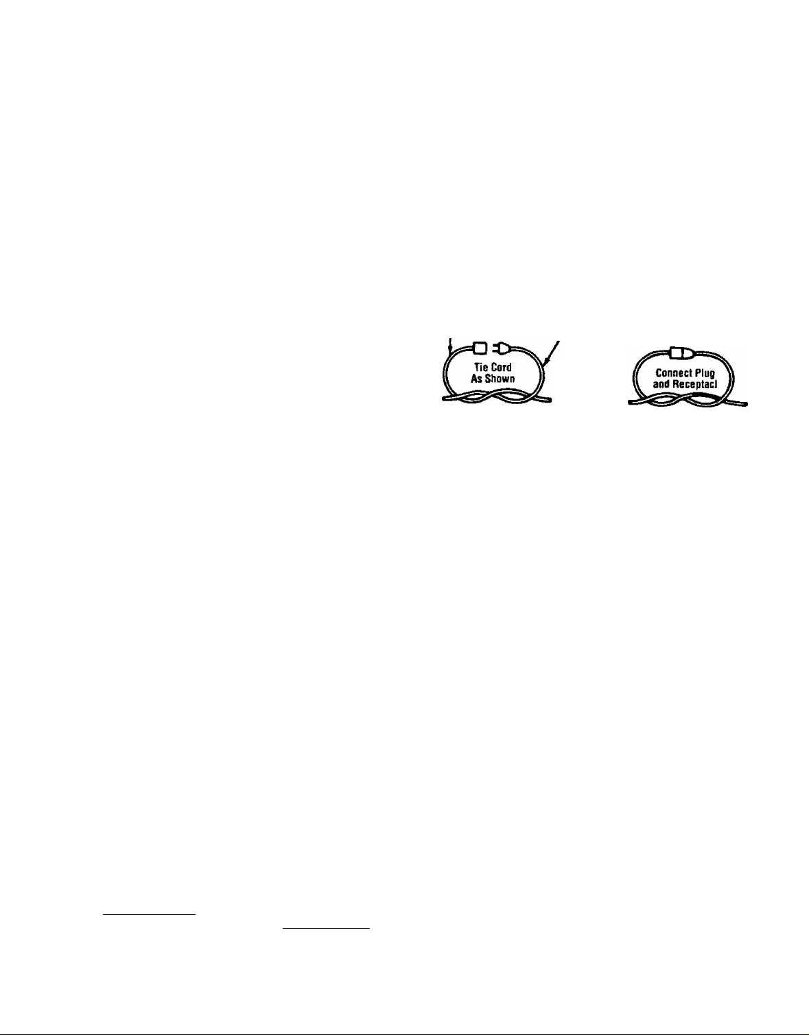
To prevent disconnection of extension cord from mower during
operation, be sure to use the cord restraint provided or make a
knot as shown in the illustration below.
Extension
Cord
Fuses—The mower should be operated on a 15 or 20 AMP cir
cuit. If difficulty in starting is experienced with a standard 15
AMP fuse or circuit breaker, contact your nearest authorized ser
vice location. Do not use a higher rated fuse without consulting
your power company.
For your safety, use the slope gauge included as part of this
manual to measure slopes before operating this unit on a sloped
or hilly area. If the slope is greater than 15“ as shown on the
slope gauge, do not operate this unit on that area or serious
injury could result.
Appliance
Cord
OPERATION
Avoid accidental starting. Do not pull plugged-in lawn mower
with finger on switch. Be sure switch is off when plugging in.
Do not abuse cord—never pull lawn mower by cord or yank it to
disconnect from receptacle. Keep cord from heat, oil, and sharp
edges.
Do not put hands or feet near or under rotating parts. Keep clear
of the discharge opening at all times as the rotating blade can
cause injury.
Stop the motor when you leave the mower and before crossing
gravel drives, walks or roads.
After striking a foreign object, shut off the motor, make absolute
ly sure the blade and all moving parts have completely stopped,
disconnect the power cord to prevent accidental starting, then
thoroughly inspect the mower for any damage. Such damage
must be repaired before restarting and operating the mower.
If the equipment should start to vibrate abnormally, stop the
motor and check immediately for the cause. Vibration is general
ly a warning of trouble.
Stop the motor, unplug the power cord, and wait for the blade
and all moving parts to stop before cleaning, unclogging chute,
removing grass catcher, repairing or inspecting the mower. The
cutting blade continues to rotate for a few seconds after the
motor is shut off.
Do not force lawn mower. It will do the job better and safer at the
rate for which it was designed. Use right appliance—Do not use
lawn mower for any job except that for which it is intended.
Page 3

SAFE OPERATION PRACTICES (Continued)
• Mow across the face of slopes, never up-and-down. Never cut
grass by pulling mower toward you. Exercise extreme caution
when operating mower on uneven terrain or changing direction
on siopes. Do not mow excessively steep slopes. Always be sure
of your footing, A slip and fail can cause serious personal injury.
• Never operate mower without proper guards, plates or other
safety protective devices in place.
• The blade/motor control on this mower is installed to minimize
the risk of blade contact injury and is required by federal regu
lations. Do not under any circumstances attempt to defeat the
function o1 the blade/motor control.
• To avoid electric shock hazard, never push mower over cord. Do
not mow around the lawn in circles. Always travel back and forth
across the lawn, beginning at the point nearest the electric outlet
to which the extension cord is connected. This will keep the cord
on the mowed area of the lawn and out of the way.
• Do not operate mower after it has been dropped or damaged in
any manner. Return mower to nearest authorized service loca
tion.
• The use of accessory attachments not recommended by the
mower manufacturer may cause hazards. The use of any acces
sory on this rotary mower other than those manufactured by the
mower manufacturer is not recommended.
• Do not operate this mower with the chute door open, unless the
complete grass catcher is properly mounted on the mower,
MAINTENANCE AND STORAGE
• Warning—Disconnect power cord from electrical outlet before
A
performing any maintenance or service on mower.
• Check the blade and motor mounting bolts at frequent intervals
for proper tightness. Keep all nuts, bolts, and screws tight to be
sure the equipment is in safe working condition.
• Keep blade sharp.
• Use identical replacement blades only. Replace damaged cord.
• To reduce fire hazard, keep the motor free of grass, leaves, or
excessive grease.
• Check the grass catcher bag frequently for wear or deterioration
and replace worn bags. For safety protection, replace only with
new bag meeting original equipment specifications.
• Store idle lawn mower indoors when not in use. Allow motor to
cool before storing in any enclosure. Lawn mower should be
stored indoors in dry, high or tocked-up place, out of reach of
children.
• Maintain lawn mower with care. Keep blade sharp and clean for
best and safest performance. Follow Instructions for lubricating
and changing accessories.
DOUBLE INSULATED LAWN MOWER
DOUBLE INSULATION IS A CONCEPT IN SAFETY IN ELECTRIC
UWN MOWERS. WHICH ELIMINATES THE NEED FOR THE USUAL
THREE WIRE GROUNDED POWER CORD AND GROUNDED SUP
PLY SYSTEM. WHEREVER THERE IS ELECTRIC CURRENT IN THE
MOWER. THERE ARE TWO COMPLETE SETS OF INSULATION TO
PROTECT THE USER. ALL EXPOSED METAL PARTS ARE ISOLAT
ED FROM THE INTERNAL METAL MOTOR COMPONENTS WITH
PROTECTING INSULATION.
IMPORTANT—SERVICING OF A LAWN MOWER WITH DOUBLE
INSULATION REQUIRES EXTREME CARE AND KNOWLEDGE OF
THE SYSTEM AND SHOULD BE PERFORMED ONLY BY A QUALI
FIED SERVICE TECHNICIAN. FOR SERVICE WE SUGGEST YOU
RETURN THE LAWN MOWER TO YOUR NEAREST AUTHORIZED
SERVICE DEALER FOR REPAIR, ALWAYS USE ORIGINAL FACTO
RY REPLACEMENT PARTS WHEN SERVICING,
Page 4

CONGRATULATIONS on your purchase of a Sears
Craftsman Lawn Mower. It has been designed, engineered
and manufactured to give you the best possible dependabil
ity and performance.
Should you experience any problem you cannot easily rem
edy, please return the lawn mower to the nearest Sears
Service Center/Department in the United States. We have
competent, well-trained technicians and the proper tools to
service or repair this unit.
Please read and retain this manual. The instructions will
enable you to assemble and maintain your lawn mower
properly. Always observe the “SAFETY RULES.”
PRODUCT SPECIFICATIONS
Voltage:
Amperage:
Hz:
Blade Bolt Torque:
110-120 AC
12
60
450-600 in. lbs.
MODEL
NUMBER
SERIAL
NUMBER
DATE OF
PURCHASE
251.370251
MAINTENANCE AGREEMENT
A Sears Maintenance Agreement is available on this
THE MODEL AND SERIAL NUMBERS WILL BE FOUND
ON A LABEL ATTACHED TO THE DECK. NEAR THE
RIGHT REAR WHEEL
YOU SHOULD RECORD BOTH SERIAL NUMBER AND
DATE OF PURCHASE AND KEEP IN A SAFE PLACE
FOR FUTURE REFERENCE.
product. Contact your nearest Sears store for details.
CUSTOMER RESPONSIBILITIES
• Read and observe the safety rules.
• Follow a regular schedule in maintaining, caring for and using your lawn mower.
• Follow the instructions under “Customer Responsibilities” (page 10) and “Storage” sections of this Owner’s
Manual.
ONE YEAR LIMITED WARRANTY ON CRAFTSMAN LAWN MOWER
For one year from the date of purchase, when this Craftsman Lawn Mower is maintained and lubricated accord
ing to the instructions in the owner’s manual, Sears will repair, free of charge, any defect in material and work
manship.
If this Craftsman Lawn Mower is used for commercial purposes, this warranty applies for only 90 days from the
date of purchase.
This warranty does not cover:
• Expendable items which become worn during normal use, such as mower blades or blade adapters.
• Repairs necessary because of operator abuse or negligence, including bent motor shafts and the failure to
maintain the equipment according to the instructions contained in the owner’s manual.
WARRANTY SERVICE IS AVAILABLE BY RETURNING THE CRAFTSMAN LAWN MOWER TO THE NEAR
EST SEARS SERVICE CENTER/DEPARTMENT IN THE UNITED STATES. THIS WARRANTY APPLIES
ONLY WHILE THIS PRODUCT IS IN USE IN THE UNITED STATES.
This warranty gives you specific legal rights, and you may also have other rights which may vary from state to
state.
SEARS, ROEBUCK AND CO., Department D/817WA, Hoffman Estates, tL 60179
Page 5

TABLE OF CONTENTS
SAFETY RULES.......................................................2
PRODUCT SPECIFICATIONS
CUSTOMER RESPONSIBILITIES
WARRANTY
INDEX
.............................................................
.......................................................................
.................................
...........................
MOWER ACCESSORIES.........................................5
ASSEMBLY
OPERATION
..............................................................
.......................................................
7-10
4
4
4
5
6
CUSTOMER RESPONSIBILITIES.....................10, 11
SERVICE AND ADJUSTMENTS...........................11
STORAGE
..............................................................
TROUBLE SHOOTING
REPAIR PARTS................................................13,14
SLOPE GAUGE......................................................15
PARTS ORDERING/SERVICE
IND E X
A
Adjustments:
Cutting Height.
Handle Height .
Assembly: Motor
Handle
...............
Grass Catcher.
.............
..............6
..............6 Wheels................
.................
Handle Storage....
9 L
Lubrication:
.................
7 M
В Maintenance:
Blade: Agreement
Balancing
Replacement...
Sharpening
..........
.......
...............
...............
...............
11
11 Cleaning
11 Lubrication
Blade Care/Replacement...
.............
c
Cleaning
Controls; R Warranty
Cord Restraint
Customer Responsibilities
Cutting Heights....
Extension Cord....
................
Motor/Blade Control
Height Adjustment Knob ...
......
.............
......
£
...............
.............
.............
.................
....3, 10, 11
...............10
......
2, 9, 11
11 Operating Mower.
Repair/Replacement Parts
8
Responsibilities, Customer
8
9 Lubrication
H
.........
........
..............
.
..............
..............
................
..............
..............
..............
12 Safety Rules
Service and Adjustments:
Cutting Height
10
10 Service Recommendations
11
11 T
10 Table of Contents
Rear Trail Shield
Specifications
Starting the Motor/Blade................
4
Stopping the Motor/Blade..............
Storage
0 Trouble Shooting Guide
..........
7-10 W
........
.......
13, 14
......
...3, 10, 11 Adjusting Height
Wheels:
..........................................
...............
BACK PAGE
S
...........
...........
.........
.........
.........
...........
....................................
............................
........................
.................................
.........
.........
............................................
...........................
.................
..........................................
........................
.................................
.........
.........
.........
...........
...........
.........
12
12
2
10
11
11
4
8
8
12
5
12
4
9
10
MOWER ACCESSORIES
These accessories were available when the mower was purchased. They are also available at most Sears retail
outlets, catalog and service centers. Most Sears stores can order repair parts for you, when you provide the
model number of your mower.
MOWER PERFORMANCE MOWER MAINTENANCE
Extension
Cord Bag
Grass
Blade
Blade
Adapter
Ч
Wheels
w
Page 6
ASSEMBLY
TO REMOVE MOWER FROM CARTON
Remove the carton inserts. Lift the mower from the car
ton, or cut the comers of the carton and roll the mower
out. Make certain all parts and literature have been re
moved from the carton before the carton is discarded.
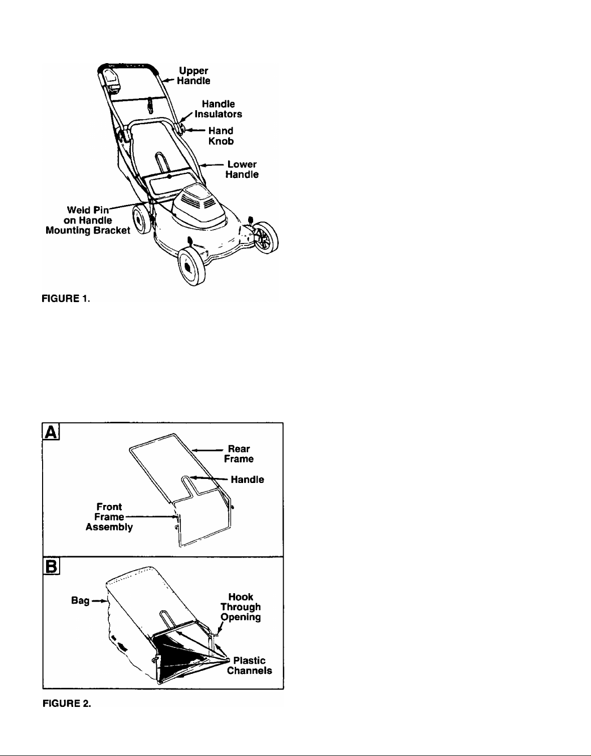
HOW TO SET-UP YOUR MOWER
• Pull up and back on the lower handle. Pivot the
upper handle up to raise the handle into the operat-
— ing position. See figure 1.
• The upper handle may be adjusted to three differ
ent height positions. To select desired position,
align one of the three marks on the top of the lower
handle insulators with the mark on the upper han
dle insulators. Tighten the hand knobs.
• Remove the hairpin clips from the outer hole in the
weld pins on the handle mounting brackets. Place
the hairpin clips in the inner hole.
NOTE; The outer hole in the weld pin is for storage.
The hairpin clip must be placed in the inner hole for
operation.
IMPORTANT: YOUR MOWER IS SHIPPED WITH
THE MULCHING BAFFLE IN PLACE. THE
MULCHING BAFFLE ALLOWS THE BLADE TO CUT
AND RECUT THE GRASS CLIPPINGS INTO SMALL
PARTICLES, RETURNING THEM TO YOUR LAWN
AS NUTRIENTS FOR THE SOIL
IF YOU WISH TO BAG INSTEAD OF MULCH THE
CLIPPINGS, SIMPLY LIFT THE REAR DISCHARGE
DOOR, AND REMOVE THE MULCHING BAFFLE
FROM THE REAR OF THE DECK BY PULLING OUT
WARD ON THE BAFFLE. THEN ASSEMBLE AND
ATTACH GRASS CATCHER AS FOLLOWS.
ASSEMBLING THE GRASS CATCHER
NOTE: Make certain the grass bag is turned right side
out before assembling (warning label will be on the
outside).
• Join the rear frame and front frame assembly as
— shown in figure 2A. Push frames together as far as
they will go.
• Place bag over frame (black plastic side is the bot
tom of bag) so the handle is outside the bag. Slip
openings in the side of the plastic channel on bag
over the hooks on the grass catcher frame.
NOTE: It may be necessary to pull the edge of the
fabric away from the plastic channel in order to see
the opening.
• Secure bag to frame by working the plastic chan
nels on bag over frame as shown in figure 2B. All
of the plastic channels except center top of bag
attach from the outside of bag. Center top of bag
attaches from the inside of bag.
Page 7

ASSEMBLY
AHACHING GRASS CATCHER TO MOWER
Lift the rear discharge door on the mower. Make cer
tain the mulching baffle has been removed. Place the
hooks on the grass catcher into the slots in the handle
-bracket assemblies. See figure 3. Release the rear
discharge door.
To remove the grass catcher, lift the rear discharge
door on the mower. Lift the grass catcher up, out of
the slots in the handle bracket assemblies. Release
the rear discharge door.
WARNING: NEVER OPERATE MOWER
UNLESS HOOKS ON GRASS CATCHER
A
ARE SEATED IN SLOTS ON HANDLE
BRACKET ASSEMBLIES, AND REAR DIS
CHARGE DOOR RESTS FIRMLY AGAINST
TOP OF GRASS CATCHER.
OPERATION
KNOW YOUR LAWN MOWER
READ THIS OWNER’S MANUAL AND SAFETY RULES BEFORE OPERATING YOUR LAWN MOWER.
Compare the illustrations with your lawn mower to familiarize yourself with the location of various controls and
adjustments. Save this manual for future reference.
MEETS CPSC BLADE SAFETY REQUIREMENTS
Sears Lawn Walk-Behind Mowers conform to the safety standards of the American National Standards Institute,
Undenwriters Laboratories, Inc., and the U.S. Consumer Product Safety Commission. The blade turns when the
engine is running.
MOTOR/BLADE CONTROL LEVER—must be held
against the handle to start and run the motor and
blade. Release to stop the motor and blade.
CORD RESTRAINT—helps prevent disconnection of
extension cord from motor/blade control.
Page 8

OPERATION
BEFORE USING YOUR LAWN MOWER, AGAIN REFER TO THE “SAFETY RULES" AS SHOWN ON PAGE 2
OF THIS MANUAL. ALWAYS BE CAREFUL.
The operation of any lawn mower can result in foreign objects being thrown into the
eyes, which can result in severe eye damage. Always wear safety glasses or eye
shields before starting power tool operation or while performing any adjustments or
repairs. We recommend Wide Vision Safety Mask for over spectacles or standard
glasses available at Sears Retail or Catalog Stores.
HOW TO USE YOUR MOWER
WARNING: DO NOT OPERATE THIS
MOWER WITH THE REAR DISCHARGE
A
A
A
DOOR OPEN, UNLESS THE COMPLETE
GRASS CATCHER IS IN PLACE. DO NOT
OPERATE THE MOWER WITHOUT THE
PROTECTIVE SHIELD ON THE REAR OF
THE DECK IN PLACE.
WARNING: BE SURE THAT LAWN IS
CLEAR OF STONES, STICKS, WIRES, OR
OTHER OBJECTS WHICH COULD DAM
AGE LAWN MOWER OR ENGINE. SUCH
OBJECTS COULD BE ACCIDENTALLY
THROWN BY THE MOWER IN ANY
DIRECTION AND CAUSE SERIOUS PER
SONAL INJURY TO THE OPERATOR AND
OTHERS.
WARNING: TO PREVENT ELECTRIC
SHOCK, DO NOT OPERATE THE MOWER
IN DAMP OR WET LOCATIONS.
WARNING: IF YOU STRIKE A FOREIGN
OBJECT, STOP THE MOTOR. DISCON
A
TO START MOTOR AND ENGAGE BLADE
Standing behind the unit, lift the motor/blade control
handle with the left forefinger, then pull handle up and
hold it against the upper handle with right hand. See
figure 5.
NECT THE POWER SOURCE, THOR
OUGHLY INSPECT THE MOWER FOR
ANY DAMAGE, AND REPAIR THE DAM
AGE BEFORE RESTARTING AND OPER
ATING THE MOWER. EXTENSIVE VIBRA
TION OF THE MOWER DURING OPERA
TION IS AN INDICATION OF DAMAGE.
THE UNIT SHOULD BE PROMPTLY
INSPECTED AND REPAIRED.
TO STOP MOTOR AND BLADE
• Release the motor/blade control handle to stop the
engine and blade. (You will hear a high pitched
noise, which is the result of deceleration of the elec
tric motor. Sparking at the lop of motor, inside the
motor cover, is also normal during deceleration.)
WARNING: THE BLADE CONTINUES TO
ROTATE FOR A FEW SECONDS AFTER
A
• Disconnect the power source to prevent accidental
starting while equipment is unattended.
THE MOTOR IS SHUT OFF. IF MOTOR
DOES NOT COME TO AN IMMEDIATE
STOP WHEN THE MOTOR/BLADE CON
TROL HANDLE IS RELEASED, CONTACT
AN AUTHORIZED SERVICE LOCATION.
FIGURE 5.
MOTOR/BLADE CONTROL
WARNING: THE MOTOR/BLADE CON
TROL ON THIS MOWER IS INSTALLED
A
The motor/blade control requires the operator to be
behind the handle to start and run the mower. When the
operator releases the control lever, the motor will stop
and an internal brake helps the blade to stop quickly.
When the operator leaves the operating position to
remove the grass catcher, change the cutting height,
or pick up sticks or other objects in the way, the motor
will stop automatically when the motor/blade control
lever is released.
TO MINIMIZE THE RISK OF BLADE CON
TACT INJURY AND IS REQUIRED BY
FEDERAL REGULATIONS. DO NOT
UNDER ANY CIRCUMSTANCES
ATTEMPT TO DEFEAT THE FUNCTION
OF THE MOTOR/BLADE CONTROL.
Page 9

OPERATION
CUTTING HEIGHT ADJUSTMENT
WARNING: TURN OFF MOTOR AND DIS
CONNECT POWER CORD BEFORE
A
Each wheel has an adjuster lever to set the cutting
height on your mower. They should always be set to
the same position.
• Raise wheels for low cut and lower wheels for high
cut.
• To change cutting height, move adjuster levers
toward wheels. See figure 6. Move wheels up or
down to suit your requirements. Be sure all four
FIGURE 6.
• Adjust cutting height to suit your requirements. Refer
They will operate easier after some use.)
CORD CONNECTION
EXTENSION CORD
IMPORTANT: USE ONLY A 100 FOOT 14 GAUGE
UL APPROVED OUTDOOR POWER EXTENSION
CORD (PART NO. 629-0192 OR EQUIVALENT). A
.SO FOOT 16 GAUGE UL APPROVED OUTDOOR
EXTENSION CORD IS AN ACCEPTABLE SUBSTI
TUTE. USING ANY OTHER LENGTH OR RATING
OF CORD WILL DIMINISH THE PERFORMANCE
AND POSSIBLY THE LIFE OF THE ELECTRIC
MOTOR.
• The length of extension cord you will need (not pro
vided with unit) depends on the size of the area to
CORD RESTRAINT
• Attach extension cord to the cord restraint as fol
tion from the motor/btade control during operation.
ADJUSTING THE CUTTING HEIGHT.
levers are in the same setting.
to the “Mowing and Mulching Tips” on page 10. (The
height adjusters may seem hard to move when new.
be mowed. See extension cord information in Safe
Operation Practices.
lows. Form a small loop in the extension cord. Allow
enough excess cord to make the connection to the
motor/btade control (approximately 20 inches). Slip
the loop through the slot on the bottom of the cord
restraint, and up over the tab, to prevent disconnec
Leave enough cord to allow the cord restraint to
move freely from side to side. See figure 7.
CONNECTION TO THE MOTOR/BLADE CONTROL
• To attach extension cord to the mower, swing open
the spring-loaded plug retainer located beneath the
motor/blade control. Connect the plug on the exten
sion cord fully onto the plug on the mower. The
mower is equipped with a polarized AC power plug
(one blade of the plug is wider than the other),
which will fit into the plug on the extension cord
only one way. See figure 7, inset. If unable to make
a full connection, try reversing the plug on the
extension cord. Should the plugs still fail to fit, con
tact your service dealer for assistance. Do not
defeat the safety purpose of the polarized plug.
Polarized Plug
Plug Retainer
(Open
Position)
Restraint
FIGURE 7.
CONNECTION TO THE ELECTRIC POWER SOURCE
• Plug the extension cord into any convenient 110-120
volt 60 cycle A.C. outlet or receptacle for your
source of power. This outlet may be located either
out-of-doors or indoors. If an inside receptacle is
used, the extension cord can be taken out either
through the doonway or a window. To avoid blowing
fuses, pick an outlet that is not overloaded. Your
mower will operate satisfactorily on a circuit that is
fused for 15 amperes. Do not use oversize fuses
without consulting your power company.
TO CONVERT MOWER TO MULCHER
• To convert the mower to a mulching mower, first
remove the grass catcher. Then simply lift the rear
discharge door, insert the mulching baffle, and
release the rear discharge door.
MOWING AND MULCHING TIPS
Never mow around the lawn in circles. Always travel
back and forth across the lawn, beginning at the point
nearest the electric outlet where cord is connected.
See figure 8. Cut grass moving away from the outlet
so the cord lies in the cut portion of the lawn, out of
the way. Do not allow extension cord to wrap around
trees, shrubs or other obstacles.
Page 10

OPERATION
The grass condition at the time of mowing determines
T = Obstacles
, ^
Outlet
Start Here
CUSTOMER RESPONSIBILITIES
the proper mower cutting height setting for best lawn
appearance. For a healthy lawn, always cut one-third
or less of the total length of the grass at any one cut
ting.
For extremely heavy cutting, reduce the width of cut.
When mulching under certain conditions, such as very
tall grass, it may be necessary to raise the height of
cut to reduce pushing effort and to keep from over
loading the engine and leaving clumps of grass clip
pings. Under heavy conditions cross cut for additional
mulching of surface debris.
When picking up the extension cord,
wind the cord in a series of equal
loops on each side of your hand to
prevent snarling. See illustration at
right.
GENERAL RECOMMENDATIONS
• Follow the Maintenance Schedule below.
MAINTENANCE SCHEDULE
SERVICE RECORD
Fill in dates as you
complete regular service
Blade Replaced
Lubricate Mower
Cleaning
V CHECK
SCHEDULE SERVICEDATES
After
Every
Use
V
First
Two
Hours
Every
25
Hours
V
V
LUBRICATION
MOTOR
The motor on your mower does not require lubrication.
WHEELS
DO NOT oil or grease the wheels. Viscous lubricants
will attract dust and dirt that will shorten the life of the
wheels. If you feel the wheels must be lubricated, use
only a dry. silicone type lubricant sparingly.
WHEEL ADJUSTERS
For easy operation, lubricate the wheel adjusters at
least once a season with light oil.
WARNING; BE CERTAIN TO DISCON
NECT THE POWER SUPPLY BEFORE
A
PERFORMING ANY REPAIRS OR MAIN
TENANCE.
10
Page 11

CUSTOMER RESPONSIBILITIES
MOWER
BLADE CARE
Your mower will work better with a sharp blade.
WARNING: BE CERTAIN TO DISCON
NECT THE POWER SUPPLY BEFORE
A
TO REMOVE BLADE (See Figure 9):
• Turn mower on its side.
• Use a block of wood between blade and mower
deck to prevent blade from turning when bolt is
wrap blade with heavy cloth.
• Remove center blade bolt by turning counterclock
wise. Use a 9/16" box or open-end wrench.
A
PERFORMING ANY MAINTENANCE.
removed. Protect your hands with gloves and/or
WARNING: PERIODICALLY INSPECT
THE BLADE ADAPTER FOR CRACKS,
ESPECIALLY IF YOU STRIKE A FOREIGN
OBJECT. REPLACE WHEN NECESSARY.
IMPORTANT: THE BOLT USED TO SECURE THE
BLADE TO THE MOTOR SHAFT IS SPECIALLY
HEAT-TREATED. DO NOT SUBSTITUTE.
CAUTION: A LOOSE BLADE CAN BE
DANGEROUS AND MAY MAKE THE
A
Use only a Sears authorized replacement blade to get
the best cutting results.
TO SHARPEN BLADE
NOTE: We do not recommend sharpening the
blade—but if you do, be sure blade is balanced.
• The blade can be sharpened with a file or on a
grinding wheel. Do not attempt to sharpen white on
the mower.
• Care should be taken to keep the blade balanced.
• To check blade balance, drive a nail into a beam or
MOTOR HARD TO START.
An unbalanced blade will cause excessive vibration
when running and eventual damage to mower and
motor.
wall. Leave about one inch of straight nail exposed.
Place center hole of blade over the head of the
nail. If blade is balanced, it should remain in a hori
zontal position. If either end of the blade moves
downward, blade is not balanced. Sharpen the
heavy end until the blade is balanced.
CLEANING
TO REPLACE BLADE (See Figure 9):
• Put blade adapter on motor shaft.
• Fit blade in adapter. Be sure trailing edge of blade
is up towards engine.
• Assemble bolts, washers, and nuts in the exact
order of removal.
• Use block of wood to hold blade and tighten bolt
clockwise. The recommended torque for the center
blade bolt is 450-600 in. lbs. The recommended
torque for the two blade adapter bolts is 200-300
in. lbs. Torque wrenches are available at most
Sears stores and through the catalog.
SERVICE AND ADJUSTMENTS
REAR TRAIL SHIELD
The rear trail shield, attached between the rear
wheels of your mower, is provided to minimize the
possibility that objects will be thrown out the rear of
the mower toward the operator. If the shield becomes
damaged, it should be replaced.
WARNING: DISCONNECT POWER SUP
A
• Remove any build-up of grass and leaves on or
around motor cover. DO NOT USE WATER.
• Clean the underside of your mower after each use
by turning the mower on its side and scraping to
remove any build-up of grass, leaves, dirt or other
matter. DO NOT USE WATER.
• Occasionally use a dry cloth to wipe mower.
• Wash grass bag periodically with water. Allow to
dry thoroughly in the shade. Do not use heat.
IMPORTANT: Under normal usage, the grass bag is
subject to wear and should be checked periodically.
Be certain any replacement bag complies with the
mower manufacturer’s specifications.
PLY BEFORE CLEANING YOUR MOWER.
TO ADJUST CUniNG HEIGHT
Refer lo “CUTTING HEIGHT ADJUSTMENT" m
Operation section of manual.
11
Page 12

STORAGE
Your mower should be prepared for off-season stor
age as follows;
MOWER
• Clean underside of mower housing (See “CLEAN
ING” in Customer Responsibilities section of manu
al).
• Inspect and replace/sharpen blade, if required (See
“BLADE CARE” in Customer Responsibilities sec
tion of manual).
• Lubricate as shown in “MAINTENANCE SCHED
ULE” (See Customer Responsibilities section of
manual).
• Make sure motor/blade control is in OFF (released)
position for storage.
HANDLE
The handle may be folded away completely for stor
age.
• Remove the grass bag (if attached).
• Loosen the hand knobs on the sides of the handle,
and let the upper handle fold down to the rear.
• Pull outward on each side of the lower handle, and
lift the sides of the lower handle past the edges of
the handle mounting brackets. Fold the lower han
dle forward.
CAUTION: When folding the handle for storage or
transportation, be careful not to bend or kink the
power cord.
To return the mower to the operating position, pull up
and back on the handle until it locks in position.
Tighten the hand knobs which secure the upper and
lower handles.
EXTENSION CORD
• Replace extension cord if cut or abraded.
• Extension cord should be wiped dry of any foreign
substances such as oil or stains.
• Wind cord and store in cool, dry place (See cord
winding instruction on page 10).
OTHER
Do not store your mower under any plastic cover.
Plastic cannot breathe which allows condensation to
form and causes metal components of mower to rust.
Trouble
Does not start
Frequent blowing of fuses
Loss of power
Poor or uneven cut
Too much vibration
Hard to push
TROUBLE SHOOTING GUIDE
Possible Cause(s)
1. Motor/blade control disengaged.
2. Extension cord disconnected.
3. Blown fuse or a tripped circuit breaker.
4. Motor/blade control switch defective.
1. Cutting too much grass.
2. Circuit overloaded.
1. Cutting too much grass.
2. Build-up of grass, leaves and debris under
mower.
1. Worn, bent or loose blade.
2. Build-up of grass, leaves and debris under
mower.
1. Worn, bent or loose blade.
2. Bent motor shaft.
1. High grass or cutting height too low.
2. Rear of mower housing and blade dragging
in heavy grass.
1. Engage motor/blade control.
2. Be sure that the extension cord is plugged
into the outlet and the lawn mower switch
plug.
3. Check to see if a fuse has been blown or a
circuit breaker tripped in your electrical box.
4. Replace motor/blade control switch.
1. Set in “Higher Cut" position.
2. Do not use a higher rated fuse without
consulting your power company. If condition
persists (be sure circuit is not overloaded),
have your unit checked by your nearest
Authorized Sears Service Dealer.
1. Set in “Higher Cur position.
2. Disconnect power cord and clean underside
of mower housing.
1. Replace blade. Tighten blade nut,
2. Disconnect power cord and clean underside
of mower housing.
1. Replace blade. Tighten blade nut,
2. Contact Sears Service Department.
1. Raise cutting height.
2. Raise cutting height.
Corrective Action
Note; For repairs beyond the minor adjustments listed above, contact your nearest SEARS Service Center.
12
Page 13

SEARS CRAFTSMAN 19" ELECTRIC MULCHING MOWER MODEL NO. 247.370251
Repair Parts
13
Page 14

SEARS CRAFTSMAN 19" ELECTRIC MULCHING MOWER MODEL NO. 247.370251
Repair Parts
KEY
NO.
PART
NO.
1 749-0881
DESCRIPTION
Upper Handle
2 747-0795 Cord Control Rod
3 725-1590
4 731-1270
5 748-0356
6 738-0102
7
732-0712
Strain Relief—Cord
Fan
Blade Adapter
Axle Bolt
Rear Flap Wire
8 731-1261 Rear Flap
9 749-0882
10 782-7025
732-0677 Door Spring—L.H.
11
12 732-0678
714-0104
13
14 764-0326
15 738-0507B
14765
16
14766
17 720-0190
732-0417A
18
710-0892
19
682-0514
20
21 682-0513
710-1017
22
Lower Handle
Chute Door
Door Spring—R.H.
Hairpin Clip
Front Catcher Frame
Shtd. Bolt .5“ Dia. x .434"
Pivot Bar—R.H.
Pivot Bar—L.H. (Not Shown)
Spring Lever Knob
Spring Lever
Hex AB-Tap Scr. 1/4 x .62" Lg.
Handle Brkt. Ass’y.—R.H.
Handle Brkt. Ass’y.—L.H.
Torx. Mach. AB-Tap Scr. 1/4 x
.62" Lg.
782-5026
23
24 736-0105
736-0356
25
26 712-0798
27 14832
15262B Pivot Bar
28
15261A
29
30 782-5025
31 782-0054
14578
32
14579
Rear Baffle
Bell-Wash. .38" l.D. x .88" O.D.
Bell-Wash. .39" l.D. x 1.38" O.D.
Hex Nut 3/8-16 Thd*
Spring Lever Ass'y. w/Knob
Height Adj. Plate
Front Baffle
19" Deck
Height Adj. Ass’y. Comp.—R.H.
Height Adj. Ass’y. Comp.—L.H.
(Not Shown)
731-1264 Motor Cover
33
34
710-1128
35 710-1150
Scr. #10-16 X.75" Lg.
Self-Tap. Scr. #7x1“ Lg.
•Common Hardware—May be purchased locally.
tPart of Motor, Switch & Cord Ass’y. Comp. (Ref. 49)
KEY
NO.
36
37
38 710-0191
39 736-0452
40
41 720-0241
42 734-1699
43
44 731-1267
45 710-0450
46
47
48 736-0331
49 818-60013
50 624-0032
PART
NO.
712-0241
710-1006
764-0447
731-1268
712-0324
726-0303
DESCRIPTION
Hex Nut 3/8-24 Thd.
Hex TT-Tap Scr. 3/8-16 x .75" Lg.
Hex Bolt 3/8-24 x 1.25" Lg.
Bell-Wash. .396" l.D. x 1.14"
Grass Bag
Plastic Knob
Wheel Ass’y. Comp.
Upper Handle Insulator
Lower Handle Insulator
Carriage Bolt 5/16-18 x 3" Lg.
Hex Top L-Nut 1/4-20 Thd.
Cable Tie
Bell-Wash. 3/8" l.D.
Motor, Cord & Switch Ass’y.
Cord & Switch Ass’y. Comp.t
51 782-5004 Mulching Baffle—R.R.
52 782-5007 Mulching Baffle Plug
53 742-0719 19" Mulching Blade
54
731-1210 Handle—Switch Actuator
55 732-0679 Spring—Switch Handle
56 725-1565
57 710-1147
729-0304
58
59 732-0680
60 731-1211
61 731-1198
Switch
Screw #6-32 X .5" Lg.
Plug Ass’y.
Retainer Plug Spring
Retainer Plug
Latch
62 624-0053 Cord Ass’y. (Incl. Ref. #58)
63 732-0681
64
731-1208
731-1209
65
Spring Latch
Housing—Upper Half
Housing—Lower Half (Not
Shown)
720-0226
66
67
720-0258
68 710-0192
720-0275 Knob
69
70 624-0031
71 724-0200
Foam Grip
Hub Cap
Truss Scr. #10-24 X.38" Lg.
Brush and Liner Ass’y.t
Brush Holder Capt
72 724-0201 End Shield Brushest
73 729-0328
729-0329 Blue Brush Leadt
74
741-0875 Needle Bearingt
75
624-0028
76
77 624-0029
724-0194
78
Red Brush Leadt
Housing Magnet Ass’y.t
Armature Ass’y.t
Motor End Platet
79 741-0124 Ball Bearingt
748-0348
80
81 725-1565
82 624-0053
710-1176
83
84 712-0324
721-0305
85
86 721-0306
724-0202
87
725-1602 Rectifiert
88
731-1207
89
736-3090
90
726-0209
91
721-0311
92
93 731-1388
94 710-1251
95 764-0325
—
770-7975J
Bearing Adapterf
Switch Motort
Cord Ass’y.t
Carriage Boltt
Hex L-Nut 1/4-20 Thd.t
Wire Insulator (Output)t
Motor Hsg. Insulatort
Cover-Rectifiert
Strain Relief Bushingt
Fl-Wash. .26" l.D. x .72" O.D.t
Cable Tie
Insulator Motor Hsg.
Insulator—Knob
Hex Bolt 3/8-24 x 2.5"
Rear Catcher Frame
Owner’s Manual
14
Page 15

USE THIS PAGE AS A GUIDE TO DETERMINE SLOPES WHERE YOU MAY NOT OPERATE SAFELY.
SIGHT AND HOLD THIS LEVEL WITH A VERTICAL TREE
A POWER POLE
A CORNER OF A BUILDING
OR A FENCE POST
•
......................
..
..........
........
.
• 1 frrTfwyi ri
..........
in
AC WARNING I
Do not mow on inclines with a slope in excess of 15 degrees (a rise of approximately 2-1/2 feet every 10 feet). A
riding mower could overturn and cause serious injury. If operating a walk-behind mower on such a slope, it is
extremely difficult to maintain your footing and you could slip, resulting in serious injury.
Operate RIDING mowers up and down slopes, never across the face of slopes.
Operate WALK-BEHIND mowers across the face of slopes, never up and down slopes.
Page 16

OWNER’S
MANUAL
MODEL NO.
247.370251
CRRFTSMRN®
110V 12AMP ELECTRIC
DOUBLE INSULATED
19 " REAR DISCHARGE
MULCHING LAWN MOWER
Each lawn mower has its own model number.
The model number for your lawn mower will be found on a
label attached to the deck, near the right rear wheel.
All parts listed herein may be ordered through Sears,
Roebuck and Co. Service Centers and most Retail Stores.
WHEN ORDERING REPAIR PARTS, ALWAYS GIVE THE
FOLLOWING INFORMATION:
* PRODUCT - ‘‘Electric Mulching Mower”
HOW TO ORDER
REPAIR PARTS
^ MODEL NUMBER - 247.370251
* PART NUMBER
* PART DESCRIPTION
Your Sears merchandise has added value when you con
sider that Sears has service units nationwide staffed with
Sears trained technicians...professional technicians specifi
cally trained on Sears products, having the parts, tools and
the equipment to insure that we meet our pledge to
you...“we service what we sell.”
SEARS, ROEBUCK AND CO., Hoffman Estates, IL
770-7975J 11/93
60179
U.S.A.
Printed In U.S.A.
Page 17

OUTDOOR POWER
PRODUCTS
P.O. Box 361131 • Cleveland, Ohio • 44136
97 Kent Avenue • Kitchener, Ontario • N2G 4J1
Page 18

 Loading...