

Craftsman 24729933 Owner’s Manual
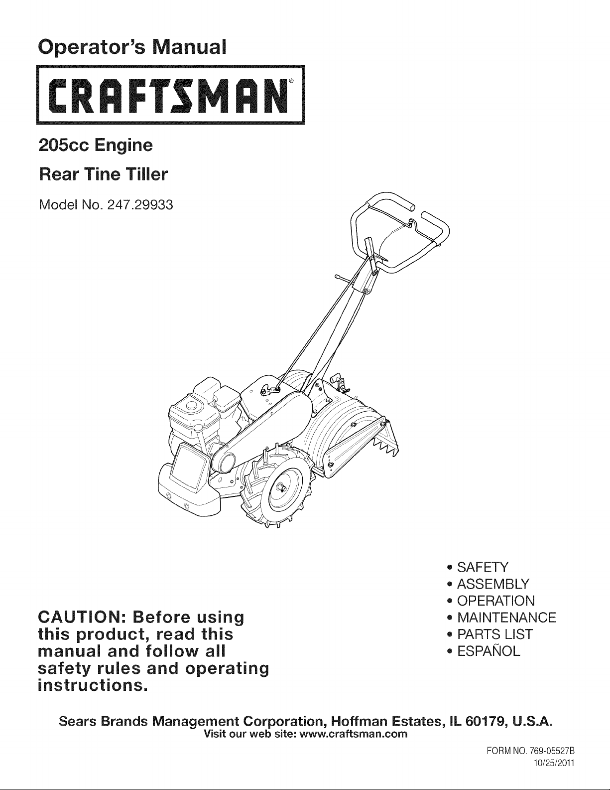
Operator's Manual
I:Rl FI'SlVl N
205cc Engine
Rear Tine Tiller
Model No. 247.29933
* SAFETY
* ASSEMBLY
* OPERATION
CAUTION: Before using
this product, read this
manual and follow aJl
* MAINTENANCE
* PARTS LIST
* ESPANOL
safety rules and operating
instructions.
Sears Brands Management Corporation, Hoffman Estates, iL 60179, U.S.A.
Visit our web site: www.craftsman.com
FORMNO.769-05527B
10/25/2011
WarrantyStatement..................................Pac
Safetyinstructions....................................Pac
Assembly..................................................Pac
Operation..................................................Pac
ServiceandMaintenance.........................Pac
Off-SeasonStorage..................................Pac
TroubleShooting.......................................Pac
e2
es3-6
es7-10
es11-16
es17-22
e23
e24
PartsList...................................................Page26-40
LabelMap.................................................Page41
RepairProtectionAgreement...................Page44
Espa_ol.....................................................Page45
ServiceNumbers......................................BackCover
CRAFTSMANONEYEAR FULL WARRANTY
FORONEYEARfromthedateofpurchase,this productiswarrantedagainstanydefectsin materialor workmanship.A defectiveproductwill
receivefreerepairorreplacementif repairis unavailable.
Forwarranty coverage details to obtain free repairor replacement,visittheweb site:www.craftsman.com
Thiswarranty isvoidifthis productiseverused while providingcommercialservicesor if rentedto another person.
Thiswarranty coversONLYdefects in material andworkmanship. Warrantycoverage does NOTinclude:
• Expendableitemsthatcan wearoutfromnormalusewithinthewarrantyperiod,includingbutnot limitedtoaugers,augerpaddles,drift
cutters,skidshoes,shaveplate,shearpins,sparkplug,air cleaner,belts,andoil filter.
• Standardmaintenanceservicing,oilchanges,or tune-ups.
Tirereplacementor repaircausedbypuncturesfromoutsideobjects,suchasnails,thorns,stumps,orglass.
• Tireor wheelreplacementor repairresultingfromnormalwear,accident,orimproperoperationor maintenance.
Repairsnecessarybecauseof operatorabuse,includingbutnotlimitedtodamagecausedbyover-speedingtheengine,or fromimpacting
objectsthatbendthe frame,augershaft,etc.
• Repairsnecessarybecauseof operatornegligence,includingbutnot limitedto,electricalandmechanicaldamagecausedby improper
storage,failureto usethepropergradeandamountof engineoil,or failureto maintaintheequipmentaccordingtothe instructionscontained
intheoperator'smanual.
• Engine(fuelsystem)cleaningor repairscausedbyfueldeterminedto becontaminatedoroxidized(stale).In general,fuelshouldbeused
within30 daysof itspurchasedate.
Normaldeteriorationandwearof theexteriorfinishes,orproductlabelreplacement.
Thiswarrantygivesyouspecificlegalrights,andyou mayalsohaveotherrightswhichvaryfromstatetostate.
Sears Brands Management Corporation, Hoffman Estates, IL 60179
EngineSeries: 205cc
EngineOilType: SAE30
EngineOilCapacity: 20ounces
Fuel: UnleadedGasoline
SparkPlug: Champion®RC-12YC
SparkPlugGap: .030"
©KCDIP,LLC 2
Model Number.................................................................
Serial Number .................................................................
Dateof Purchase.............................................................
Recordthemodelnumber,serialnumber
anddateof purchaseabove
Thissymbolpointsout importantsafetyinstructionswhich,if not
followed,couldendangerthepersonalsafetyand/orpropertyof
yourselfandothers. Readandfollowall instructionsin thismanual
beforeattemptingtooperatethismachine.Failuretocomplywith
theseinstructionsmayresultin personalinjury.Whenyou seethis
symbol,HEEDITSWARNING!
Thismachinewasbuiltto beoperatedaccordingto thesafeopera-
tionpracticesinthismanual.Aswithanytypeof powerequipment,
carelessnessorerroronthe partof theoperatorcan resultin
seriousinjury.Thismachineiscapableofamputatingfingers,hands,
toesandfeetandthrowingdebris.Failureto observethefollowing
safetyinstructionscouldresultin seriousinjuryordeath.
CALIFORNIA PROPOSITION 65
EngineExhaust,someof itsconstituents,andcertainvehicle
componentscontainoremitchemicalsknowntoStateof California
tocausecancerandbirthdefectsorotherreproductiveharm.Bat-
tery posts,terminals,andrelatedaccessoriescontainleadand lead
compounds,chemicalsknowntothe Stateof Californiatocause
cancerandreproductiveharm.Washhandsafterhandling.
TRAINING
• Read,understand,andfollowall instructionson the machineand
in themanual(s)beforeattemptingtoassembleandoperate.
Keepthis manualina safeplaceforfutureand regularreference
andfororderingreplacementparts.
• ReadtheOperator'sManualand followallwarningsandsafety
instructions.Failuretodosocan resultin seriousinjuryto the
operatorand/or bystanders.Forquestions,call1-800-4MY-HOME.
• Befamiliarwithall controlsandtheirproperoperation.Knowhow
tostopthe machineanddisengagethemquickly.
• Neverallowchildrenunder14yearsof agetooperatethis
machine.Children14andovershouldreadandunderstandthe
instructionsandsafeoperationpracticesin thismanualandon
themachineandbe trainedandsupervisedbyanadult.
• Neverallowadultstooperatethis machinewithoutproper
instruction.
• Keepbystanders,pets,andchildrenatleast75feetfromthe
machinewhileit isin operation.Stopmachineifanyoneenters
thearea.
• Neverrunanengineindoorsor ina poorlyventilatedarea.Engine
exhaustcontainscarbonmonoxide,anodorlessanddeadlygas.
Your Responsibility--Restrictthe useof thispowermachineto
personswhoread,understandandfollowthewarningsandinstruc-
tionsin thismanualandon the machine.
SAVETHESEINSTRUCTIONS!
PREPARATION
• Thoroughlyinspecttheareawheretheequipmentistobeused.
Removeall rocks,bottles,cans,or otherforeignobjectswhich
couldbepickedupor thrownandcausepersonalinjuryor
damageto themachine.
• Alwayswearsafetyglassesor safetygogglesduringoperation
andwhileperformingan adjustmentorrepair,to protectyour
eyes.Thrownobjectswhichricochetcancauseseriousinjuryto
theeyes.
• Wearsturdy,rough-soledworkshoesandclose-fittingslacksand
shirts.Loosefittingclothesorjewelrycan becaughtin movable
parts.Neveroperatethismachineinbarefeetorsandals.
• Beforestarting,checkallboltsandscrewsfor propertightnessto
besurethe machineisinsafeworkingcondition.Also,visually
inspectmachinefor anydamageatfrequentintervals.
• Disengageclutchleversandshift(if provided)into neutral("N")
beforestartingtheengine.
• Neverleavethismachineunattendedwiththeenginerunning.
• Neverattempttomakeanyadjustmentswhilethe engineis
running,exceptwherespecificallyrecommendedinthe operator's
manual.
• Maintainorreplacesafetyandinstructionslabels,asnecessary.
3
SafeHandling of Gasoline:
Toavoidpersonalinjuryor propertydamageuseextremecarein
handlinggasoline.Gasolineisextremelyflammableandthe vaporsare
explosive.Seriouspersonalinjurycan occurwhengasolineisspilled
onyourselforyourclotheswhichcan ignite.Washyourskinand
changeclothesimmediately.
• Useonlyan approvedgasolinecontainer.
• Neverfill containersinsidea vehicleor ona truckor trailerbed
witha plasticliner.Alwaysplacecontainersonthe groundaway
fromyourvehiclebeforefilling.
• Whenpractical,removegas-poweredequipmentfromthetruck
ortrailerand refuelitonthe ground.Ifthisis notpossible,then
refuelsuchequipmentona trailerwitha portablecontainer,rather
thanfroma gasolinedispensernozzle.
• Keepthe nozzleincontactwiththerimofthe fueltankor
containeropeningatalltimes untilfuelingiscomplete.Donotuse
a nozzlelock-opendevice.
• Extinguishallcigarettes,cigars,pipesandother sourcesof
ignition.
• Neverfuel machineindoors.
• Neverremovegascapor addfuel whilethe engineishot or run-
ning.Allowenginetocool atleasttwo minutesbeforerefueling.
• Neveroverfillfueltank.Fill tankto nomorethan1/2inchbelow
bottomoffillerneckto allowspacefor fuelexpansion.
• Replacegasolinecapandtightensecurely.
• Ifgasolineisspilled,wipe itoff theengineandequipment.Move
unitto anotherarea.Wait5 minutesbeforestartingtheengine.
• To reducefirehazards,keepmachinefreeof grass,leaves,or
otherdebrisbuild-up.Cleanupoil orfuelspillageand removeany
fuelsoakeddebris.
• Neverstorethe machineorfuelcontainerinsidewherethereis an
openflame,sparkor pilotlightas on awaterheater,spaceheater,
furnace,clothesdryerorothergasappliances.
OPERATION
• Do notputhandsorfeetnear rotatingparts.Contactwiththe
rotatingpartscanamputatehandsandfeet.
• Do notoperatemachinewhileunderthe influenceofalcoholor
drugs.
• Neveroperatethismachinewithoutgoodvisibilityor light.Always
be sureof yourfootingandkeepa firmholdonthehandles.
• Keepbystandersawayfromthe machinewhileit isinoperation.
Stopthe machineif anyoneentersthearea.
• Becarefulwhentillinginhardground.Thetines maycatchinthe
groundandpropelthetillerforward.Ifthis occurs,let goofthe
handlebarsanddo not restrainthemachine.
• Exerciseextremecautionwhenoperatingonor crossinggravel
surfaces.Stayalertforhiddenhazardsortraffic. Donotcarry
passengers.
• Neveroperatethemachineat hightransportspeedsonhardor
slipperysurfaces.
• Exercisecautiontoavoidslippingorfalling.
• Lookdownand behindandusecarewhenin reverseor pulling
machinetowardsyou.
• Startthe engineaccordingtothe instructionsfoundinthis manual
and keepfeetwell awayfromthetinesat all times.
• Afterstrikingaforeignobjector ifyourmachineshouldstartmak-
inganunusualnoiseor vibration,immediatelyshutthe engineoff.
Disconnectthe sparkplugwire,grounditagainstthe engineand
performthefollowingsteps:
a. Inspectfordamage.
b. Repairorreplaceanydamagedparts.
c. Checkforanyloosepartsandtightento assurecontinued
safeoperation.
• Disengageall clutchlevers(iffitted)and stopenginebeforeyou
leavethe operatingposition(behindthe handles).Waituntil
thetinescometo a completestopbeforeuncloggingthe tines,
makinganyadjustments,or inspections.
• Neverrunanengineindoorsorina poorlyventilatedarea.Engine
exhaustcontainscarbonmonoxide,an odorlessanddeadlygas.
• Mufflerandenginebecomehotandcancausea burn.Do not
touch.
• Usecautionwhentillingnearfences,buildingsandunderground
utilities.Rotatingtinescan causepropertydamageorpersonal
injury.
• Donotoverloadmachinecapacitybyattemptingtotillsoil too
deepattoo fastof a rate.
• Ifthe machineshouldstartmakinganunusualnoiseor vibration,
stoptheengine,disconnectthesparkplugwire andgroundit
againsttheengine.Inspectthoroughlyfordamage.Repairany
damagebeforestartingandoperating.
• Keepallshields,guards,and safetydevicesinplaceandoperat-
ing properly.
• Neverpickuporcarrymachinewhiletheengineis running.
• Useonly attachmentsandaccessoriesapprovedbythe manu-
factureras listedin thePartsListpagesofthisoperator'smanual.
Failuretodosocan resultin personalinjury.
• Ifsituationsoccurwhichare notcoveredinthis manual,usecare
andgoodjudgement.ContactCustomerSupportat 1-800-4MY-
HOMEforassistanceandthenameof thenearestservicedealer
MAINTENANCE & STORAGE
• Keepthemachine,attachmentsandaccessoriesin safeworking
order.
• Allowthemachinetocoolat leastfiveminutesbeforestoring.
Nevertamperwithsafetydevices.Checktheirproperoperation
regularly.
• Checkboltsandscrewsforpropertightnessat frequentintervals
to keepthemachineinsafeworkingcondition.Also,visually
inspectmachineforanydamage.
• Beforecleaning,repairing,or inspecting,stopthe engineand
makecertainthetinesandall movingpartshavestopped.
Disconnectthe sparkplugwireandgrounditagainsttheengineto
preventunintendedstarting.
4
• Do notchangetheenginegovernorsettingsor over-speedthe
engine.Thegovernorcontrolsthemaximumsafeoperatingspeed
ofengine.
Maintainor replacesafetyandinstructionlabels,as necessary.
Followthis manualfor safeloading,unloading,transporting,and
storageof thismachine.
Alwaysreferto theoperator'smanualforimportantdetailsifthe
machineisto bestoredforan extendedperiod.
If thefuel tankhasto be drained,do thisoutdoors.
Observeproperdisposallawsandregulationsforgas,oil, etc.to
protecttheenvironment.
Accordingtothe ConsumerProductsSafetyCommission(CPSC)
andtheU.S.EnvironmentalProtectionAgency(EPA),thisproduct
hasan AverageUsefulLifeof seven(7)years,or 130hoursof
operation.Atthe endof theAverageUsefulLifehavethemachine
inspectedannuallybyanauthorizedservicedealertoensurethat
allmechanicalandsafetysystemsareworkingproperlyandnot
wornexcessively.Failureto do socan resultinaccidents,injuries
ordeath.
DO NOT MODIFY ENGINE
Toavoidseriousinjuryordeath,donot modifyenginein anyway.
Tamperingwiththegovernorsettingcan leadto a runawayengineand
causeitto operateat unsafespeeds.Nevertamperwithfactorysetting
ofenginegovernor.
NOTICE REGARDING EMISSIONS
EngineswhicharecertifiedtocomplywithCaliforniaandfederal
EPAemissionregulationsfor SORE(SmallOff RoadEquipment)are
certifiedto operateonregularunleadedgasoline,and mayinclude
thefollowingemissioncontrolsystems:EngineModification(EM),
OxidizingCatalyst(CO),SecondaryAirInjection(SAI)and ThreeWay
Catalyst(TWO)if soequipped.
SPARK ARRESTOR
Thismachineis equippedwithan internalcombustionengineand
shouldnotbe usedonor nearanyunimprovedforest-covered,
brushcoveredor grass-coveredlandunlesstheengine'sexhaust
systemisequippedwitha sparkarrestormeetingapplicablelocalor
statelaws(if any)
Ifa sparkarrestorisused,it shouldbe maintainedin effectiveworking
orderbytheoperator.Inthe StateofCaliforniatheaboveisrequired
bylaw (Section4442ofthe CaliforniaPublicResourcesCode).Other
statesmayhavesimilarlaws. Federallawsapplyonfederallands.
A sparkarrestorforthe muffleris availablethroughyournearestSears
PartsandRepairServiceCenter.
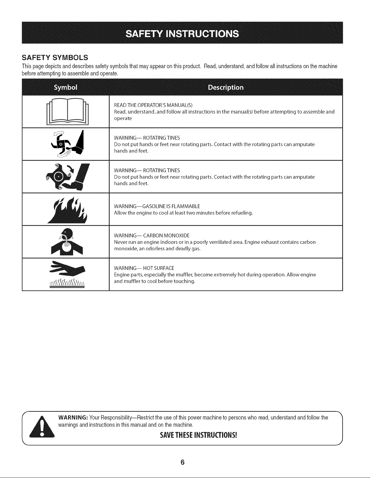
SAFETY SYMBOLS
Thispagedepictsanddescribessafetysymbolsthatmayappearonthisproduct. Read,understand,andfollowallinstructionson themachine
beforeattemptingto assembleandoperate.
READ THE OPERATOR'S MANUAL(S)
i
i
Read, understand, and follow all instructions in the manual(s) before attempting to assemble and
operate
WARNING-- ROTATING TINES
Do not put hands or feet near rotating parts. Contact with the rotating parts can amputate
hands and feet.
WARNING-- ROTATING TINES
Do not put hands or feet near rotating parts. Contact with the rotating parts can amputate
hands and feet.
WARNING--GASOLINE IS FLAMMABLE
Allow the engine to cool at least two minutes before refueling.
WARNING-- CARBON MONOXIDE
Never run an engine indoors or in a poorly ventilated area. Engine exhaust contains carbon
monoxide, an odorless and deadly gas.
WARNING-- HOT SURFACE
Engine parts, especially the muffler, become extremely hot during operation. Allow engine
and muffler to cool before touching.
WARNING: YourResponsibility--Restricttheuseofthispowermachineto personswhoread,understandandfollowthe
warningsand instructionsinthis manualandonthemachine.
SAVETHESEINSTRUCTIONS!
6
NOTE:Thisunitis shippedwithoutgasolineor oil intheengine.Be
certaintoserviceenginewithgasolineandoil as instructedin the
Operationsectionofthis manualbeforeoperatingyourmachine.
NOTE:Referenceto rightand lefthandsideof thetiller isobserved
fromtheoperatingposition.
OPENING CARTON
1. Removethe staples,breaktheglueonthetopflaps,orcutthe
tapeat theendof thecartonand peelit alongthetopflapto open.
2. Removealllooseparts.
3. Cutthecornersandlaythecartondown fiat.
4. Removeloosepackingmaterial.
REMOVING UNIT FROM CARTON
1. Usethehandlebartoliftand pullthetiller backwardstoa flat
area.Checkthecartonthoroughlyforlooseparts.
2. Extendthecontrolcableandlayit on thefloor.Becarefulnot to
bendor kinkthecontrolcable.
LOOSE PARTS IN CARTON
• HandlebarAssembly
• Tiller
• EngineOil
• Operator'sManual
• ShiftRod
• DepthStake
ATTACHING THE DEPTH STAKE
3. Raisethefine shieldhingeflapassemblyand insertthedepth
stakeassemblyinthe slot,underthe fineshieldandup through
thetine shieldassembly.
4. Inserttheclevispinthroughthefineshieldanddepthstake
assemblies.Secureitwiththe cotterpin.
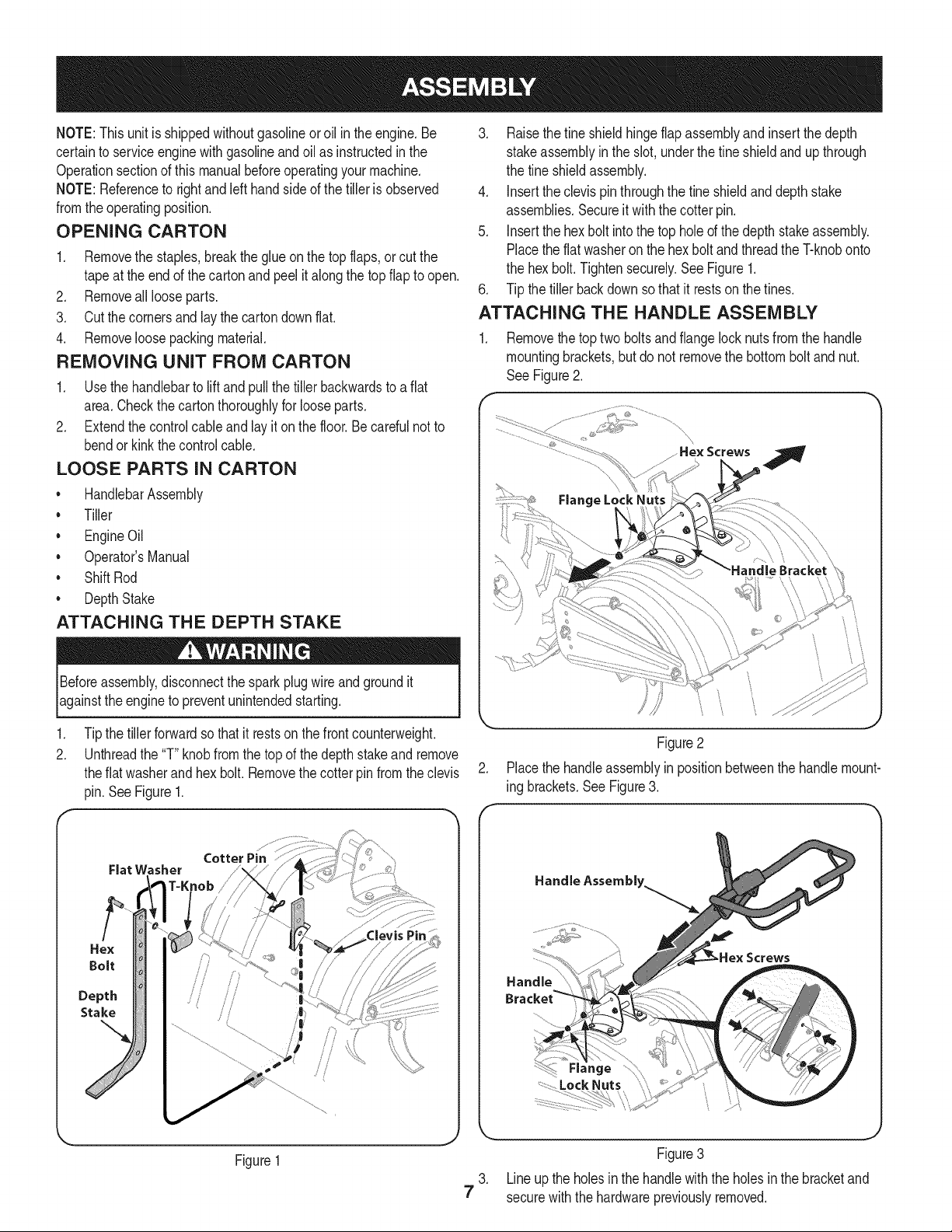
5. Insertthehexbolt intothe topholeofthedepthstakeassembly.
Placetheflatwasheronthehex boltandthreadtheT-knobonto
thehex bolt.Tightensecurely.SeeFigure1.
6. Tipthetillerbackdownsothatit restsonthe tines.
ATTACHING THE HANDLE ASSEMBLY
1. Removethetoptwoboltsandflangelocknutsfromthehandle
mountingbrackets,but do notremovethebottomboltandnut.
See Figure2.
f
He× Screws
Beforeassembly,disconnectthesparkplugwireandgroundit
againsttheengineto preventunintendedstarting.
1. Tipthetillerforwardso thatitrestson thefrontcounterweight.
2. Unthreadthe"T"knobfromthetopofthedepthstakeand remove
theflat washerandhexbolt. Removethecotterpinfromtheclevis
pin.SeeFigure1.
Flat Washer
Hex
Cotter Pin
Bolt
Depth
Stake
Figure1
\
Figure2
.
Placethehandleassemblyin positionbetweenthe handlemount-
ing brackets.See Figure3.
Handle Assembly.
Figure3
3. Lineup theholesinthehandlewiththeholesin thebracketand
7
securewiththehardwarepreviouslyremoved.
J
ATTACHING THE CONTROL ROD
1. Makesurethehandleassemblyis inthehighestposition.Referto
theOperationSection.
2. Removethehairpinclipsfromthecontrolrod,putthe rubber
washersinplace.
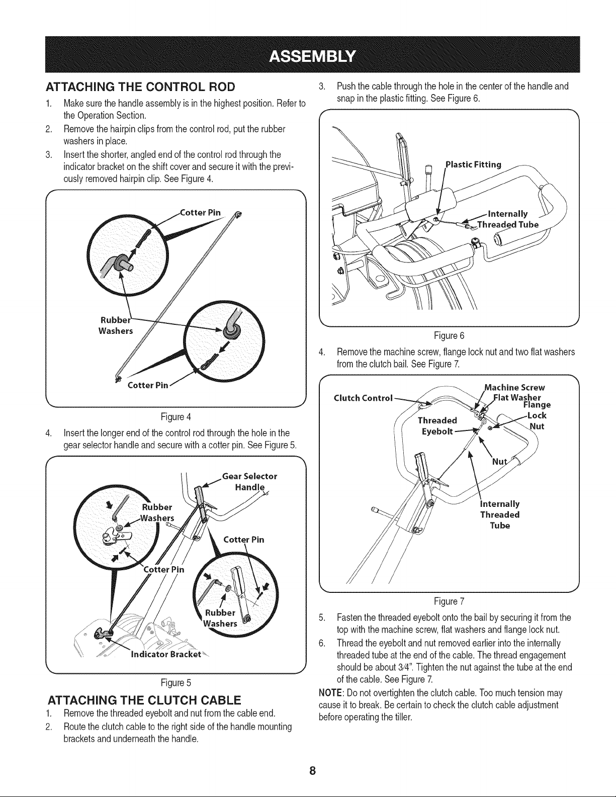
3. Insertthe shorter,angledendof thecontrolrodthroughthe
indicatorbracketonthe shiftcoverandsecureit withtheprevi-
ouslyremovedhairpinclip.SeeFigure4.
Rubb_
Washers
3. Pushthecablethroughthe holein thecenterofthehandleand
snapinthe plasticfitting.SeeFigure6.
Threaded Tube
Figure6
Removethe machinescrew,flangelocknut andtwoflatwashers
fromtheclutchbail.See Figure7.
Figure4
4. Insertthe longerendofthe controlrodthroughthe holeinthe
gearselectorhandleandsecurewitha cotterpin.SeeFigure5.
Gear Selector
Handle
Cotter Pin
Figure5
ATTACHING THE CLUTCH CABLE
1. Removethethreadedeyeboltandnutfromthe cableend.
2. Routetheclutchcableto therightsideof thehandlemounting
bracketsandunderneaththe handle.
Machine Screw
Clutch Control Flat Washer
Range
Nut
internally
Threaded
Tu be
Figure7
5. Fastenthe threadedeyeboltontothebailbysecuringitfromthe
topwiththe machinescrew,flatwashersandflangelocknut.
6. Threadtheeyeboltandnutremovedearlierintotheinternally
threadedtubeatthe endof thecable.Thethreadengagement
shouldbeabout3/4".Tightenthenutagainstthetubeattheend
ofthe cable.SeeFigure7.
NOTE:Donotovertightentheclutchcable.Toomuchtensionmay
causeitto break.Becertaintochecktheclutchcableadjustment
beforeoperatingthetiller.
8
SET-UP
Tire Pressure
Checktheair pressureinbothtires.Theairpressureshouldbe
between15-20PSI.Keepbothtiresequallyinflatedtohelpprevent
machinefrompullingtoone side.
Checking and Adding Oil
Theengineis shippedwithoutoil in theengine.Youmustfill the
enginewithoil beforeoperating.Runningtheenginewithinsufficient
_o cancauseserous engnedamageandvod the productwarranty.
Initial Use
1. Removetheoil filldipstick.
2. Placethetilleron levelground,usea funnelto emptyentire
contentsofthe oil bottleprovidedwiththe tillerintotheengine.
3. Replacetheoilfilldipstickandtighten.
Checkingand adding oil
1. Placethetillerona flat, levelsurface.
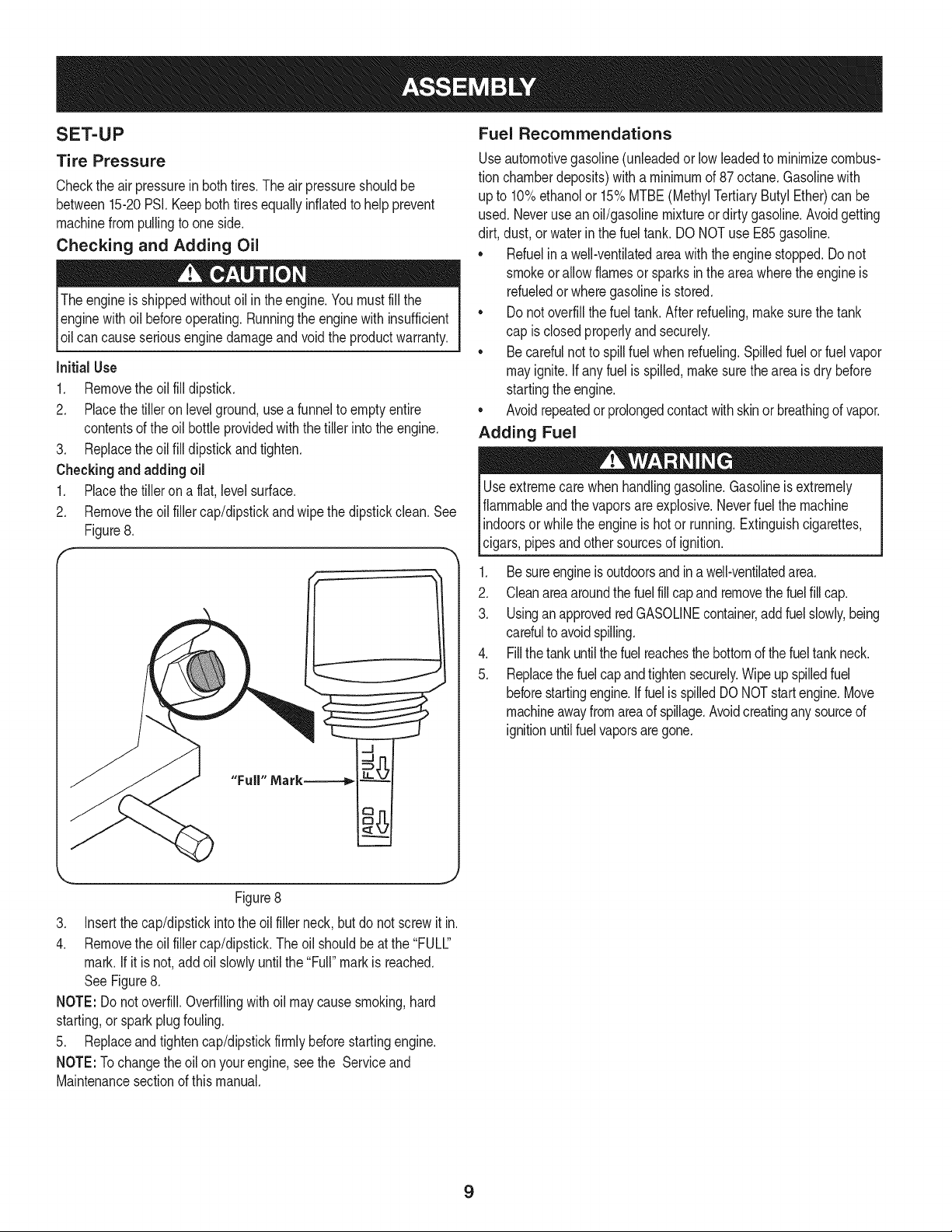
2. Removetheoil fillercap/dipstickandwipethedipstickclean.See
Figure8.
Fuel Recommendations
Useautomotivegasoline(unleadedorlowleadedtominimizecombus-
tionchamberdeposits)witha minimumof 87 octane.Gasolinewith
up to 10%ethanolor 15%MTBE(MethylTertiaryButylEther)canbe
used.Neverusean oil/gasolinemixtureordirty gasoline.Avoidgetting
dirt, dust,or waterinthe fueltank.DONOTuse E85gasoline.
• Refuelina well-ventilatedareawiththe enginestopped.Donot
smokeorallowflamesor sparksin theareawheretheengineis
refueledor wheregasolineisstored.
• Donotoverfillthe fueltank.After refueling,makesurethe tank
capis closedproperlyandsecurely.
• Becarefulnotto spillfuelwhenrefueling.Spilledfuelorfuel vapor
mayignite.Ifany fuelis spilled,makesurethe areaisdry before
startingthe engine.
• Avoidrepeatedor prolongedcontactwithskinorbreathingofvapor.
Adding Fuel
Useextremecarewhenhandlinggasoline.Gasolineisextremely
flammableandthevaporsareexplosive.Neverfuelthe machine
indoorsorwhilethe engineishotor running.Extinguishcigarettes,
cigars,pipesandothersourcesof ignition.
1. Besureengineisoutdoorsandina well-ventilatedarea.
2. Cleanareaaroundthefuelfill capandremovethefuelfill cap.
3. UsinganapprovedredGASOLINEcontainer,addfuelslowly,being
carefultoavoidspilling.
4. Fillthetankuntilthefuelreachesthe bottomofthefueltankneck.
5. Replacethefuelcapandtightensecurely.Wipeupspilledfuel
beforestartingengine.IffuelisspilledDONOTstartengine.Move
machineawayfromareaofspillage.Avoidcreatinganysourceof
ignitionuntilfuelvaporsaregone.
Figure8
3. Insertthe cap/dipstickintothe oilfillerneck,butdo not screwitin.
4. Removetheoil fillercap/dipstick.Theoilshouldbeatthe"FULC'
mark.If itisnot,addoil slowlyuntilthe "Full"markisreached.
SeeFigure8.
NOTE:Donotoverfill.Overfillingwithoil maycausesmoking,hard
starting,or sparkplugfouling.
5. Replaceandtightencap/dipstickfirmlybeforestartingengine.
NOTE:Tochangethe oilon yourengine,seethe Serviceand
Maintenancesectionofthismanual.
9
ADJUSTMENTS
Priortooperatingyourtiller,carefullyreadandfollowall instructions
below.Performall adjustmentsto verifyyourtilleris operatingsafely
andpropery.
Clutch Cable
NOTE:Servicethe enginewithoil andgasolinebeforecheckingthis
adjustment.Referto theseparateEngineOperator'sManualpacked
withyourtillerforproperfuel andengineoil recommendations.
1. Positionthetillerso thefrontcounterweightis againsta solid
object,suchas a wall.
2. WiththegearselectionleverinNEUTRAL,starttheengine.Refer
tothe separateEngineOperator'sManual.
3. Standingonthe rightsideofthe tiller,examinethebelt (insidethe
beltcover).It shouldnotbeturning.
Donot putyourfingersunderthebelt cover.
.
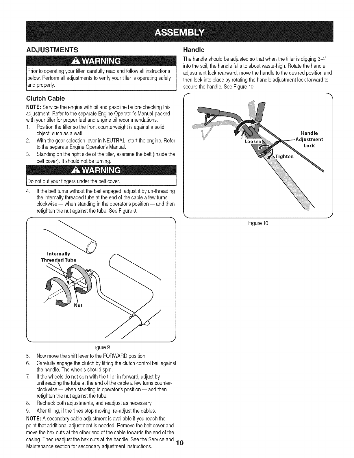
If thebeltturnswithoutthebailengaged,adjustitbyun-threading
theinternallythreadedtubeat theendof thecablea fewturns
clockwise-- when standingin theoperator'sposition-- andthen
retightenthenut againstthetube.SeeFigure9.
f
Handle
Thehandleshouldbeadjustedsothatwhenthetillerisdigging3-4"
intothe soil,the handlefallsto aboutwaste-high.Rotatethehandle
adjustmentlock rearward,movethe handleto thedesiredpositionand
thenlockintoplaceby rotatingthehandleadjustmentlockforwardto
securethehandle.SeeFigure10.
Handle
Loosen
tighten
ustment
Lock
Figure10
Internally
ThreadedTube
Figure9
,
Nowmovetheshiftleverto theFORWARDposition.
6.
Carefullyengagethe clutchby liftingtheclutchcontrolbailagainst
thehandle.Thewheelsshouldspin.
7.
If thewheelsdo not spinwiththe tillerinforward,adjustby
unthreadingthe tubeat theendof thecablea fewturnscounter-
clockwise-- when standingin operator'sposition-- andthen
retightenthenut againstthetube.
,
Recheckbothadjustments,andreadjustas necessary.
9.
Aftertilling,ifthe tinesstopmoving,re-adjustthe cables.
NOTE:A secondarycableadjustmentisavailableifyoureachthe
pointthatadditionaladjustmentisneeded.Removethebeltcoverand
movethehexnutsatthe otherendof thecabletowardstheendofthe
casing.Thenreadjustthehex nutsatthe handle.Seethe Serviceand
Maintenancesectionforsecondaryadjustmentinstructions.
10
Gear
Handle Adjustment
Clutch Control
Muffler
\
I
Fuel Cap
Air Filter. _ I__
Shift Lever indicator
Stake
Recoil!ta_
Rear Tine Shield
Figure11
Nowthat youhavesetup yourtillerforoperation,getacquaintedwith TH ROTTLE CONTROL
itscontrolsandfeatures.Thesearedescribedonthe nexttwopages
andillustratedonthispage.Thisknowledgewillallowyouto useyour
newequipmenttoitsfullestpotential.
Theoperationofanytillercanresultinforeignobjectsbeingthrowninto
theeyes,whichcandamageyoureyesseverely.Alwayswearsafety
assesdurn o eratonorwh e erformn an adustmentsorre a rs.
Thethrottlecontrolregulatesthespeedofthe engineandwill shutoff
theenginewhenit is movedintothe STOPO position.Thethrottle
controlmovesbetweenthe FAST_ (rabbit),SLOW_ (turtle)
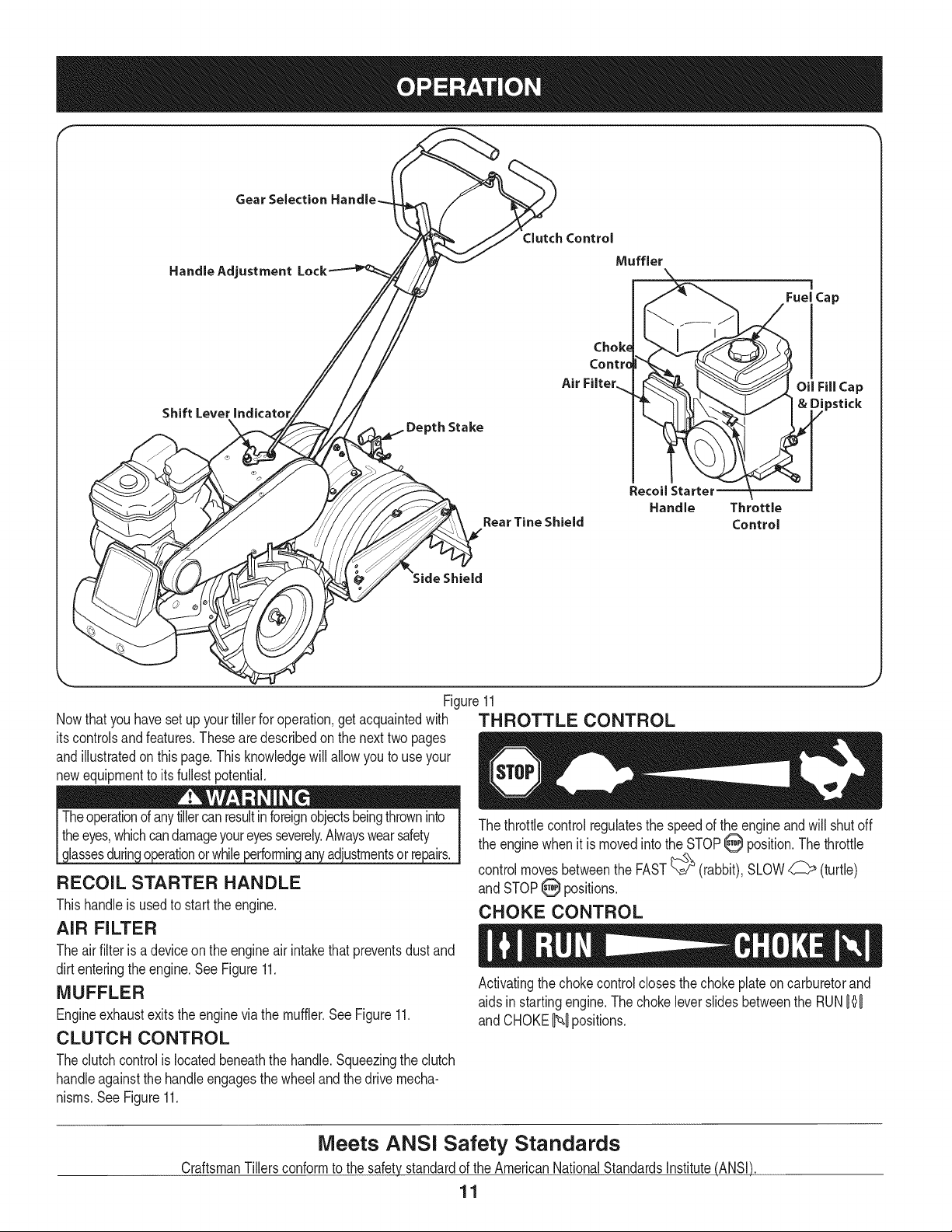
RECOIL STARTER HANDLE
Thishandleisusedto starttheengine.
and STOPO positions.
CHOKE CONTROL
AIR FILTER
Theair filteris adeviceontheengineair intakethatpreventsdustand
dirtenteringtheengine.SeeFigure11.
MUFFLER
Engineexhaustexitstheenginevia themuffler.SeeFigure11.
Activatingthechokecontrolclosesthechokeplateon carburetorand
aidsin startingengine.ThechokeleverslidesbetweentheRUN0{'0
and CHOKEN positions.
CLUTCH CONTROL
Theclutchcontrolislocatedbeneaththehandle.Squeezingtheclutch
handleagainstthehandleengagesthewheelandthedrivemecha-
nisms.SeeFigure11.
Oil Fill Cap
& Dipstick
Handle Throttle
Control
Meets ANSI Safety Standards
CraftsmanTillersconformtothe safetystandardofthe AmericanNationalStandardsInstitute(ANSI)
11
OiL FiLL CAP & DIPSTICK
Engineoil levelcanbecheckedandoiladdedthroughtheoil fill. See
Figure11.
NOTE:ThisunitwasshippedWITHOUToil inthe engine.Oilis
includedintheplasticbag packedwiththemanualinwiththetiller.
Addtheoil as directedintheGas & OilFillUp section.Checktheoil
levelbeforeeachoperationtoensureadequateoil is intheengine.
Forfurtherinstructions,refertothestepsintheEngineMaintenance
sectionof thismanual.
GEAR SELECTION HANDLE
TO START ENGINE
1. Attachsparkplugwireandrubberboot tosparkplug.
2. Filltankto no morethan 1/2" belowbottomoffillerneckto
providespaceforfuelexpansion.
3. Placethegearselectionleverin NEUTRAL.
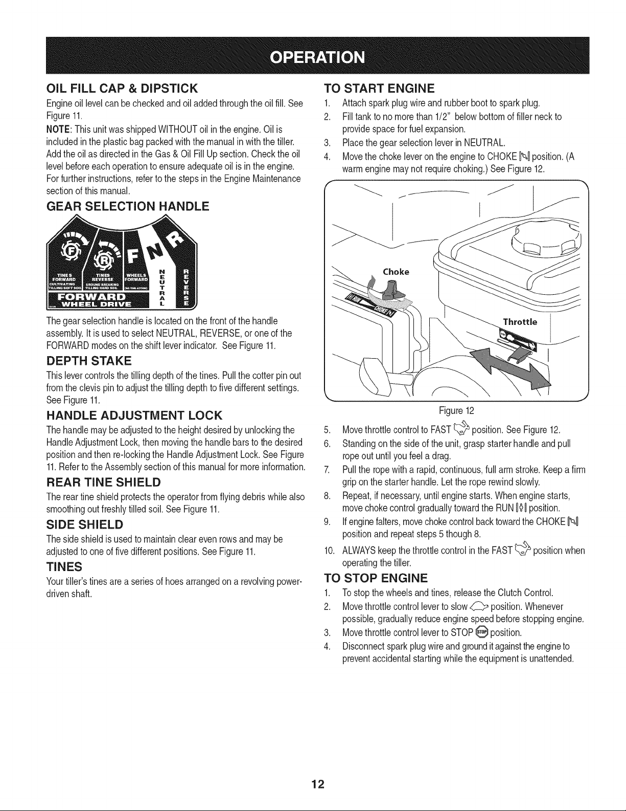
4. Movethechokeleveron theengineto CHOKEN position.(A
warmenginemaynotrequirechoking.)SeeFigure12.
Choke
Thegearselectionhandleislocatedonthe frontof thehandle
assembly.It is usedto selectNEUTRAL,REVERSE,oroneof the
FORWARDmodeson the shiftleverindicator.SeeFigure11.
DEPTH STAKE
Thislevercontrolsthetillingdepthof thetines.Pullthecotter pinout
fromtheclevis pintoadjustthe tillingdepthtofivedifferentsettings.
SeeFigure11.
HANDLE ADJUSTMENT LOCK
Thehandlemaybe adjustedtotheheightdesiredbyunlockingthe
HandleAdjustmentLock,thenmovingthehandlebarsto thedesired
positionandthenre-lockingtheHandleAdjustmentLock.SeeFigure
11.Referto theAssemblysectionofthis manualformoreinformation.
REAR TIME SHIELD
Thereartine shieldprotectstheoperatorfromflyingdebriswhilealso
smoothingout freshlytilledsoil.SeeFigure11.
SIDE SHIELD
Theside shieldis usedto maintainclearevenrowsandmaybe
adjustedtooneof fivedifferentpositions.SeeFigure11.
TINES
Yourtiller'stinesarea seriesof hoesarrangedona revolvingpower-
drivenshaft.
Throttle
Figure12
5. Movethrottlecontrolto FAST_ position.SeeFigure12.
6. Standingon the sideof theunit,graspstarterhandleandpull
ropeoutuntilyoufeela drag.
7. Pullthe ropewitha rapid,continuous,fullarm stroke.Keepafirm
gripon thestarterhandle.Letthe roperewindslowly.
8. Repeat,ifnecessary,untilenginestarts.Whenenginestarts,
movechokecontrolgraduallytowardthe RUN0'_0position.
9. Ifenginefalters,movechokecontrolbacktowardtheCHOKEN
positionand repeatsteps5 though8.
10. ALWAYSkeepthethrottlecontrolin theFAST_ positionwhen
operatingthetiller.
TO STOP ENGINE
1. To stopthewheelsandtines, releasetheClutchControl.
2. Movethrottlecontrolleverto slow_ position.Whenever
possible,graduallyreduceenginespeedbeforestoppingengine.
3. Movethrottlecontrolleverto STOPO position.
4. Disconnectsparkplugwireandgrounditagainsttheengineto
preventaccidentalstartingwhilethe equipmentisunattended.
12
TO ENGAGE DRIVE & TINES
Donot pushdownon thehandlebarstotry to makethetillertill more
deeply.This preventsthe wheelsfromholdingthetiller backandcan
allowthe tinesto rapidlypropelthetiller,whichcould resultin lossof
control,propertydamage,orpersonalinjury.
Tomoveforward:
1. Forforwardmotionofthewheelsusethe gearselectionhandle
andforpowertothe tinespulltheclutchcontrolupagainstthe
handlebar.
2. Whentilling,letthewheelspullthe machinewhilethetinesdig.
Walkslowlybehindthetillerallowingitto moveatits ownpace
whilekeepinga securegripon thehandlebarwithyourelbows
flexed.
3. Releasethebailto stopthewheelsandtines.
Tomoveinreverse:(Donot tillin reverse)
1. Releasethe ClutchControl.Thenliftthe handlebaruntilthe tines
areoff theground.
2. Pullbackonthegearselectionhandle,andwalkbackwardswith
themachine.
NOTE:In reversemode,thetineswill reverserotation.
TURNING THE TILLER
1. Practiceturningthetillerin a level,openarea.Beverycarefulto
keepyourfeetandlegsawayfromthe tines.
2. Tobeginaturn,liftthe handlebarsuntilthetinesareout ofthe
groundandtheengineandtinesarebalancedoverthewheels.
3. Withthetillerbalanced,pushsidewayson the handlebartosteer
in thedirectionoftheturn.Afterturning,slowlylowerthe tinesinto
thesoil toresumetilling.
SETTING THE DEPTH
Tillingdepthiscontrolledbythedepthstakewhichcan be adjustedto
fivedifferentsettings.Adjustthesideshieldsasyou adjustthedepth
stake.
• Whenusingthe tillerfor thefirsttime,usethesecondadjustment
holefromthetop (1"oftillingdepth).
• Whenbreakingupsodandforshallowcultivation,usethe setting
whichgives1"oftillingdepth(secondholefromthetop).Place
thesideshieldsintheirlowestposition.
• Forfurtherdepth,raisethedepthstakeandsideshieldsandalso
makeoneor twomorepassesoverthearea.
• Whentillingloosesoil,thedepthstakemayberaisedtoits
highestposition(usebottomadjustmenthole)to givethedeepest
tillingdepth.Raisethe sideshieldsto theirhighestposition.
• Totransporttiller,lowerthedepth stake(usetopadjustment
hole).
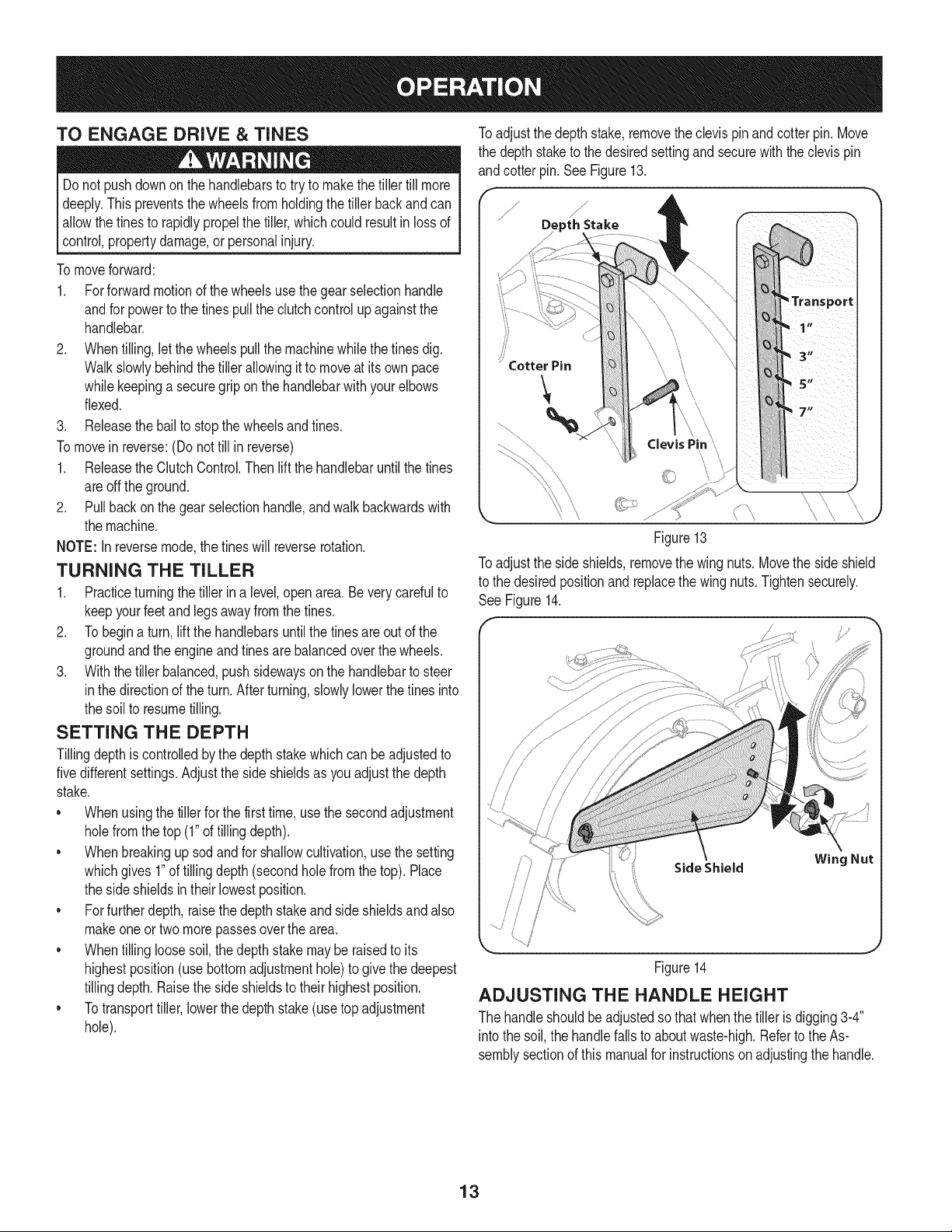
Toadjustthedepthstake,removetheclevispinandcotterpin.Move
thedepthstaketo thedesiredsettingandsecurewiththeclevispin
andcotterpin.SeeFigure13.
j_
DepthStake
Figure13
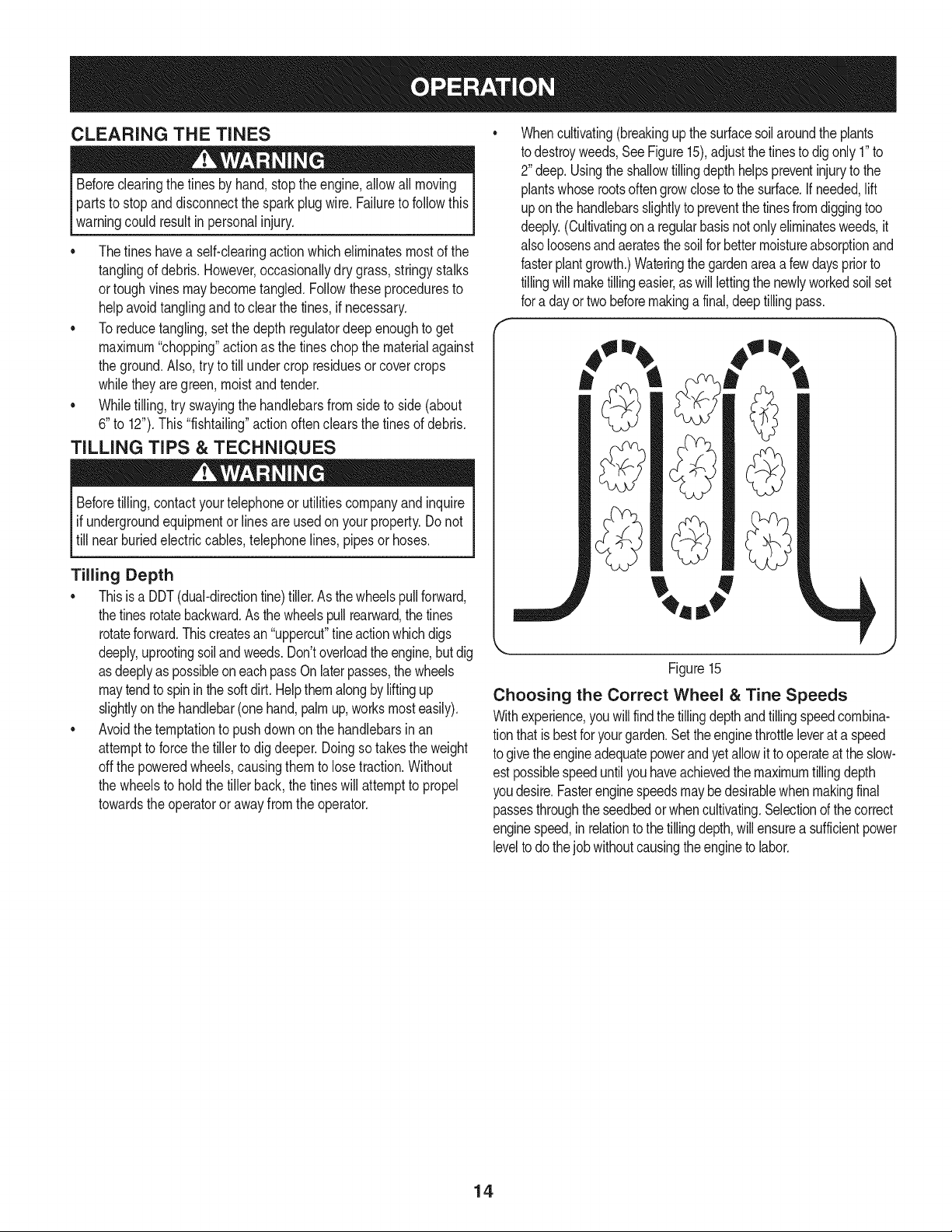
Toadjustthe sideshields,removethewingnuts.Movethesideshield
tothe desiredpositionandreplacethewingnuts.Tightensecurely.
See Figure14.
f J
/
!
_h J
Side Shield Wing Nut
Figure14
ADJUSTING THE HANDLE HEIGHT
Thehandleshouldbeadjustedsothat whenthetillerisdigging3-4"
intothe soil,thehandlefallsto aboutwaste-high.RefertotheAs-
semblysectionofthis manualforinstructionson adjustingthehandle.
13
CLEARING THE TINES
Beforeclearingthetinesby hand,stoptheengine,allowallmoving
partstostopanddisconnectthesparkplugwire.Failuretofollowthis
warningcouldresultinpersonalinjury.
• Thetines haveaself-clearingactionwhicheliminatesmostofthe
tanglingofdebris.However,occasionallydrygrass,stringystalks
ortoughvinesmaybecometangled.Followtheseproceduresto
helpavoidtanglingandtoclearthetines, ifnecessary.
• To reducetangling,setthedepthregulatordeepenoughtoget
maximum"chopping"actionasthetineschopthe materialagainst
theground.Also,trytotill undercropresiduesorcovercrops
whiletheyaregreen,moistandtender.
• Whiletilling,try swayingthehandlebarsfromsideto side(about
6"to 12").This"fishtailing"actionoftenclearsthetinesof debris.
TILLING TiPS & TECHNIQUES
Beforetilling,contactyourtelephoneor utilitiescompanyandinquire
l ifundergroundequipmentorlinesareusedon yourproperty.Donot
[till nearburiedelectriccables,telephonelines,pipesor hoses.
Tilling Depth
• Thisisa DDT(dual-directiontine)tiller.Asthewheelspullforward,
thetinesrotatebackward.As thewheelspullrearward,the tines
rotateforward.Thiscreatesan "uppercut"fineactionwhichdigs
deeply,uprootingsoilandweeds.Don'toverloadtheengine,butdig
asdeeplyaspossibleoneachpassOnlaterpasses,thewheels
maytendto spininthe softdirt.Helpthemalongbyliftingup
slightlyonthehandlebar(onehand,palmup,worksmosteasily).
• Avoidthetemptationto pushdownonthehandlebarsinan
attempttoforcethetillerto digdeeper.Doingsotakestheweight
off thepoweredwheels,causingthemto losetraction.Without
thewheelsto holdthetillerback,the tineswillattemptto propel
towardstheoperatororawayfromthe operator.
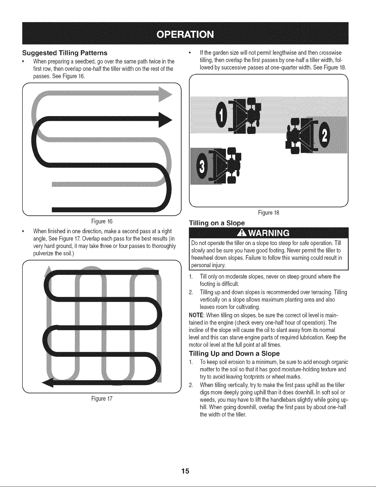
Whencultivating(breakingupthesurfacesoilaroundtheplants
todestroyweeds,SeeFigure15),adjustthe tinestodigonly1"to
2"deep.Usingtheshallowtillingdepthhelpspreventinjurytothe
plantswhoserootsoftengrowclosetothesurface.Ifneeded,lift
uponthehandlebarsslightlyto preventthetinesfromdiggingtoo
deeply.(Cultivatingona regularbasisnotonlyeliminatesweeds,it
alsoloosensandaeratesthesoilforbettermoistureabsorptionand
fasterplantgrowth.)Wateringthegardenareaafewdayspriorto
tillingwillmaketillingeasier,as willlettingthenewlyworkedsoilset
fora dayortwobeforemakingafinal,deeptillingpass.
,j
Figure15
Choosing the Correct Wheel & Tine Speeds
Withexperience,you willfindthetillingdepthandtillingspeedcombina-
tionthatisbestforyourgarden.Settheenginethrottleleverata speed
togivetheengineadequatepowerandyetallowittooperateattheslow-
estpossiblespeeduntilyouhaveachievedthemaximumtillingdepth
youdesire.Fasterenginespeedsmaybedesirablewhenmakingfinal
passesthroughtheseedbedor whencultivating.Selectionofthe correct
enginespeed,inrelationto thetillingdepth,willensurea sufficientpower
leveltodothejobwithoutcausingtheenginetolabor.
14
Suggested Tilling Patterns
• Whenpreparinga seedbed,gooverthe samepathtwice inthe
firstrow,thenoverlapone-halfthetiller widthontherestof the
passes,SeeFigure16,
• Ifthe gardensizewillnotpermitlengthwiseandthencrosswise
tilling,thenoverlapthefirst passesbyone-halfatiller width,fol-
lowedby successivepassesatone-quarterwidth.SeeFigure18.
Figure16
Whenfinishedinonedirection,makea secondpassata right
angle,SeeFigure17.Overlapeachpassfor thebestresults(in
veryhardground,it maytakethreeorfour passestothoroughly
pulverizethesoil.)
== ==== ==d
Figure17
J
Tilling on a Slope
Donotoperatethetillerona slopetoosteepfor safeoperation.Till
slowlyandbesureyouhavegoodfooting.Neverpermitthetillerto
freewheeldownslopes.Failuretofollowthiswarningcouldresultin
personalinjury.
1. Till onlyon moderateslopes,neveronsteepgroundwherethe
footingisdifficult.
2. Tillingupand downslopesisrecommendedoverterracing.Tilling
verticallyon aslopeallowsmaximumplantingareaandalso
leavesroomforcultivating.
NOTE:Whentillingon slopes,be surethe correctoillevelismain-
tainedin theengine(checkeveryone-halfhourofoperation).The
inclineof theslopewillcausethe oilto slantawayfromitsnormal
levelandthis canstarveenginepartsof requiredlubrication.Keepthe
motoroil levelat thefull pointat all times.
Tilling Up and Down a Slope
1. To keepsoilerosionto a minimum,besureto addenoughorganic
matterto thesoil sothat it hasgoodmoisture-holdingtextureand
try toavoidleavingfootprintsor wheelmarks.
2. Whentillingvertically,tryto makethefirst passuphillasthetiller
J
digsmoredeeplygoinguphillthanit doesdownhill.Insoft soilor
weeds,youmayhaveto liftthehandlebarsslightlywhilegoingup-
hill.Whengoingdownhill,overlapthefirstpassby aboutone-half
thewidthof thetiller.
Figure18
15
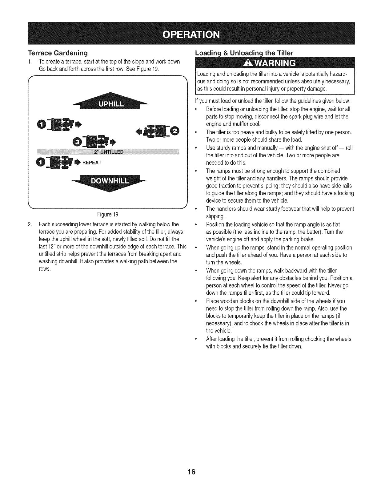
Terrace Gardening
1. Tocreatea terrace,startatthetopof theslopeandworkdown
Gobackandforthacrossthefirstrow.See Figure19.
f
to,
O
tI'REPEAT
Figure19
.
Eachsucceedinglowerterraceis startedby walkingbelowthe
terraceyouarepreparing.Foraddedstabilityof thetiller,always
keepthe uphillwheelin the soft,newlytilledsoil.Donottill the
last 12"ormoreof thedownhilloutsideedgeofeachterrace.This
untilledstriphelps preventtheterracesfrombreakingapart and
washingdownhill.Italsoprovidesawalkingpathbetweenthe
rOWS.
Loading & Unloading the Tiller
Loadingandunloadingthetillerintoa vehicleis potentiallyhazard-
Ious anddoingsois notrecommendedunlessabsolutelynecessary,
las thiscould resultin personalinjuryorpropertydamage.
Ifyoumustloadorunloadthetiller,followthe guidelinesgivenbelow:
• Beforeloadingorunloadingthetiller,stopthe engine,waitfor all
partsto stopmoving,disconnectthesparkplugwireandletthe
engineand mufflercool.
• The tilleris tooheavyand bulkyto besafelyliftedbyone person.
Twoor morepeopleshouldsharethe load.
• Usesturdyrampsand manually-- withtheengineshutoff-- roll
thetiller intoandout ofthe vehicle.Twoormorepeopleare
neededtodo this.
• The rampsmustbe strongenoughto supportthecombined
weightofthe tillerandanyhandlers.The rampsshouldprovide
goodtractionto preventslipping;theyshouldalsohaveside rails
toguidethe tilleralongthe ramps;andtheyshouldhavea locking
deviceto securethemto thevehicle.
J
• The handlersshouldwearsturdyfootwearthatwill helptoprevent
slipping.
• Positiontheloadingvehiclesothatthe rampangleis asflat
as possible(thelessinclineto theramp,the better).Turnthe
vehicle'sengineoffandapplytheparkingbrake.
• Whengoinguptheramps,standin thenormaloperatingposition
and pushthetilleraheadof you.Havea personateachsideto
turnthe wheels.
• Whengoingdownthe ramps,walkbackwardwiththetiller
followingyou.Keepalertfor anyobstaclesbehindyou.Positiona
personateachwheeltocontrolthe speedof thetiller.Nevergo
downthe rampstiller-first,asthetillercouldtip forward.
• Placewoodenblockson thedownhillsideof thewheelsif you
needtostopthe tillerfromrollingdowntheramp.Also,usethe
blockstotemporarilykeepthetiller in placeonthe ramps(if
necessary),andto chockthe wheelsin placeafterthe tilleris in
thevehicle.
• Afterloadingthe tiller,preventitfromrollingchockingthewheels
with blocksandsecurelytiethe tillerdown.
16
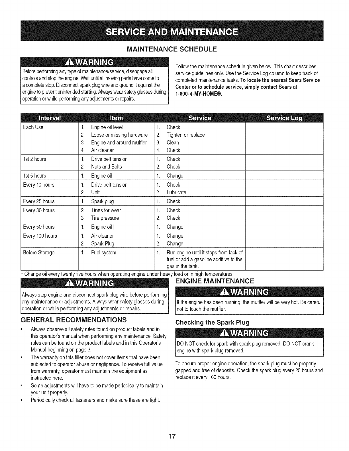
MAINTENANCE SCHEDULE
Beforeperforminganytypeofmaintenance/service,disengageall
controlsandstoptheengine.Waituntilallmovingpartshavecometo
acompletestop.Disconnectsparkplugwireandgrounditagainstthe
enginetopreventunintendedstarting.Alwayswearsafetyglassesduring
serviceguidelinesonly.UsetheServiceLogcolumnto keeptrackof
completedmaintenancetasks.To locate the nearest Sears Service
Centeror to scheduleservice,simplycontactSearsat
1-800-4-MY-HOME®.
operationor whileperforminganyadjustmentsor repairs.
Followthemaintenanceschedulegivenbelow.Thischartdescribes
= =
EachUse
1st2 hours
1st5 hours
Every10hours
Every25 hours
Every30 hours
Every50 hours
Every100hours
BeforeStorage
1. Engineoillevel
2. Looseormissinghardware
3. Engineandaroundmuffler
4. Aircleaner
1. Drivebelttension
2. Nutsand Bolts
1. Engineoil
1. Drivebelttension
2. Unit
1. Sparkplug
2. Tinesforwear
3. Tirepressure
1. Engineoilf
1. Aircleaner
2. SparkPlug
1. Fuelsystem
1. Check
2. Tightenor_place
3. Clean
4. Check
1. Check
2. Check
1. Change
1. Check
2. Lubricate
1. Check
1. Check
2. Check
1. Change
1. Change
2. Change
1. Runengineuntilit stopsfromlackof
fueloradda gasolineadditivetothe
gasin thetank.
Changeoileverytwentyfivehourswhenoperatingengineunderheavyloadorinhightemperatures.
ENGINE MAINTENANCE
Alwaysstopengineanddisconnectsparkplugwirebeforeperforming
lanymaintenanceor adjustments.Alwayswearsafetyglassesduring
_operationorwhile performinganyadjustmentsor repairs.
GENERAL RECOMMENDATIONS
• Alwaysobserveallsafetyrulesfoundonproductlabelsandin
thisoperator'smanualwhenperforminganymaintenance.Safety
rulescan befoundonthe productlabelsandin thisOperator's
Manualbeginningon page3.
• Thewarrantyonthistillerdoesnotcoveritemsthathavebeen
subjectedto operatorabuseor negligence.Toreceivefullvalue
fromwarranty,operatormustmaintaintheequipmentas
instructedhere.
• Someadjustmentswillhaveto be madeperiodicallytomaintain
yourunit properly.
• Periodicallycheckall fastenersand makesurethesearetight.
Iftheenginehas beenrunning,themufflerwillbeveryhot.Becareful
notto touchthemuffler.
Checking the Spark Plug
DONOTcheckforsparkwithsparkplugremoved.DONOTcrank
enginewithsparkplug removed.
Toensureproperengineoperation,thesparkplugmustbeproperly
gappedandfreeof deposits.Checkthe sparkplugevery25hoursand
replaceitevery100hours.
17
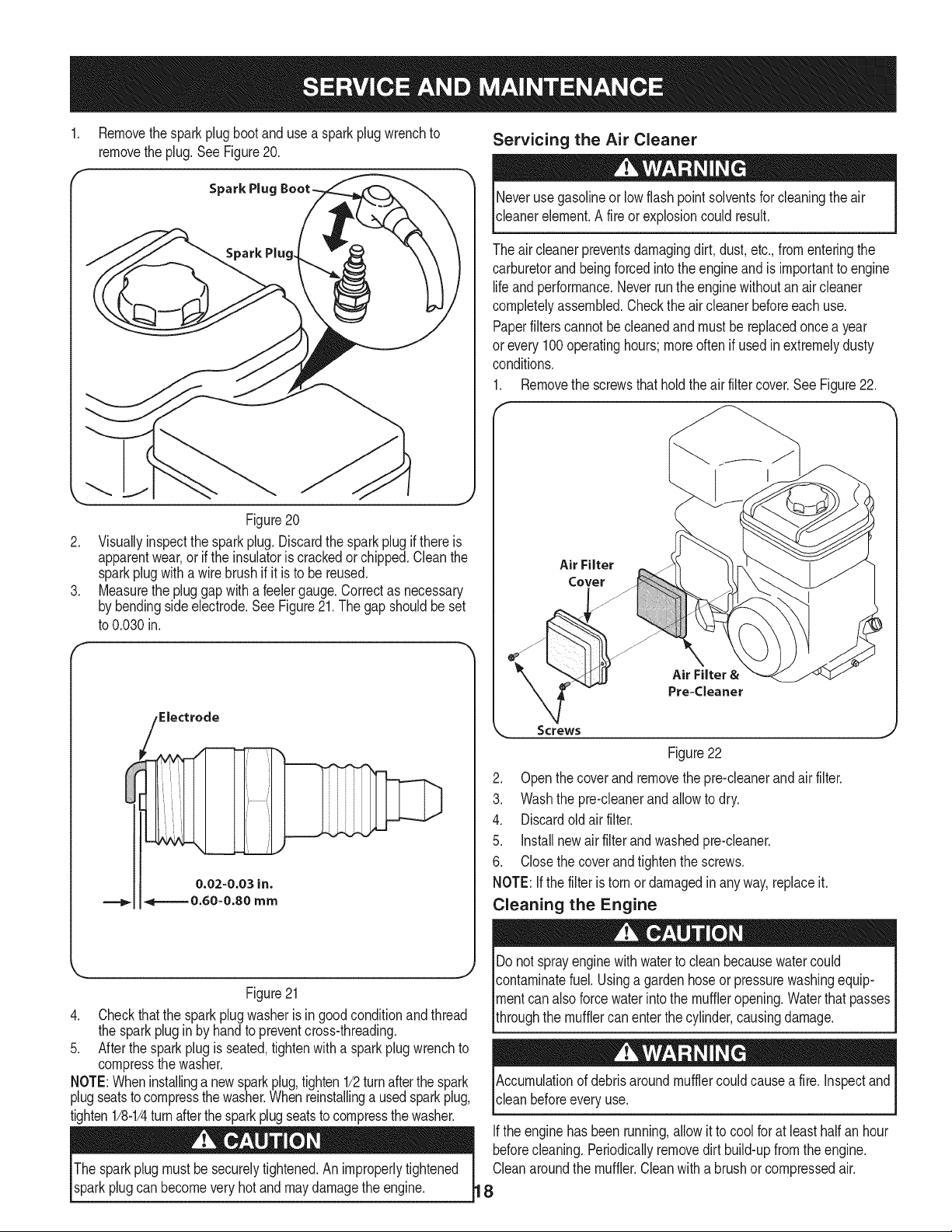
Removethesparkplugbootanduse a sparkplugwrenchto
removetheplug.See Figure20.
Servicing the Air Cleaner
Spark Plug
Figure20
2. Visuallyinspectthesparkplug.Discardthesparkplugif thereis
apparentwear,orif the insulatoriscrackedorchipped.Cleanthe
sparkplugwitha wirebrush ifit isto be reused.
3. Measurethepluggapwithafeelergauge.Correctas necessary
bybendingsideelectrode.SeeFigure21.The gapshouldbeset
to0.030in.
Neverusegasolineor lowflashpoint solventsforcleaningtheair
cleanerelement.A fireor explosioncouldresult.
Theaircleanerpreventsdamagingdirt,dust,etc.,fromenteringthe
carburetorandbeingforcedintothe engineandis importanttoengine
lifeandperformance.Neverruntheenginewithoutanair cleaner
completelyassembled.Checktheair cleanerbeforeeachuse.
Paperfilterscannotbecleanedand mustbereplacedoncea year
or every100operatinghours;moreoftenif usedinextremelydusty
conditions.
1. Removethescrewsthatholdtheairfiltercover.SeeFigure22.
Air Filter
Cover
Figure21
4. Checkthatthe sparkplugwasherisingoodconditionandthread
thesparkplugin by handtopreventcross-threading.
5. Afterthesparkplugisseated,tightenwitha sparkplugwrenchto
compressthewasher.
NOTE:Wheninstallinga newsparkplug,tighten1/2turnafterthespark
plugseatstocompressthewasher.Whenreinstallinga usedsparkplug,
tighten1/8-1/4turnafterthesparkplugseatstocompressthewasher.
Thesparkplugmustbe securelytightened.An improperlytightened
sparkplugcanbecomeveryhot andmaydamagetheengine.
Air Filter &
Pre=Cleaner
Screws
Figure22
2. Openthecoverandremovethepre-cleanerandairfilter.
3. Washthe pre-cleanerandallowtodry.
4. Discardoldair filter.
5. installnewair filterandwashedpre-cleaner.
6. Closethecoverandtightenthe screws.
NOTE:Ifthe filteristornor damagedinany way,replaceit.
Cleaning the Engine
Donotsprayenginewithwatertocleanbecausewatercould
contaminatefuel.Usinga gardenhoseor pressurewashingequip-
mentcanalsoforcewaterintothe muffleropening.Waterthatpasses
throughthe mufflercanenterthe cylinder,causingdamage.
Accumulationofdebrisaroundmufflercouldcausea fire. inspectand
cleanbeforeeveryuse.
Iftheenginehas beenrunning,allow itto coolfor at leasthalf anhour
beforecleaning.Periodicallyremovedirt build-upfromtheengine.
Cleanaroundthemuffler.Cleanwitha brushor compressedair.
8
Check Engine Oil
1. Checkoilbeforeeachuse.Stopengineandwaitseveralminutes
beforecheckingoil level.Withengineon levelground,theoilmust
beto FULLmarkon dipstick.
2. Refertothe Assemblysectionofthismanualforinstructionson
checkingtheoil.
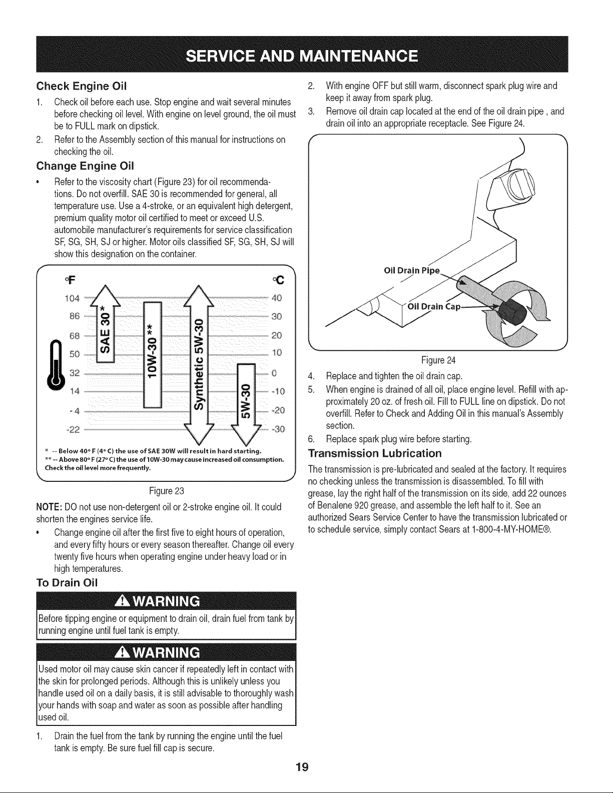
Change Engine Oil
Refertothe viscositychart(Figure23)for oil recommenda-
tions.Do notoverfill.SAE30 is recommendedforgeneral,all
temperatureuse.Usea 4-stroke,oranequivalenthighdetergent,
premiumqualitymotoroilcertifiedto meetorexceedU.S.
automobilemanufacturer'srequirementsforserviceclassification
SF,SG,SH,SJ or higher.MotoroilsclassifiedSF,SG,SH,SJ will
showthisdesignationon thecontainer.
2. WithengineOFFbutstillwarm,disconnectsparkplugwireand
keepit awayfromsparkplug.
3. Removeoil draincap locatedatthe endofthe oildrainpipe, and
drainoil intoanappropriatereceptacle.See Figure24.
OilDrain
J
104
86
68
50
32
14
o4
,-22
-- Below 40 ° F (4 ° C) the use of SAE 30W will result in hard starting,
_ -- Above 80 ° F (27 ° C) the use of 10W-30 may cause increased oil consumption,
Check the oil level more frequently,
Figure23
NOTE:DOnotusenon-detergentoil or2-strokeengineoil.it could
shortentheenginesservicelife.
• Changeengineoil afterthefirst fivetoeight hoursofoperation,
andeveryfifty hoursoreveryseasonthereafter.Changeoil every
twentyfivehourswhenoperatingengineunderheavyloadorin
hightemperatures.
To Drain Oil
ii
4O
2O
_10
_20
I°
o30
ain Ca
Figure24
4. Replaceandtightentheoildraincap.
5. Whenengineis drainedofall oil, placeenginelevel.Refillwithap-
proximately20oz.offreshoil. Fillto FULLlineondipstick.Do not
overfill.Referto CheckandAddingOilin thismanual'sAssembly
section.
6. Replacesparkplugwirebeforestarting.
Transmission Lubrication
Thetransmissionispro-lubricatedandsealedatthefactory,it requires
no checkingunlessthetransmissionis disassembled.Tofill with
grease,laythe righthalfof thetransmissionon itsside,add22ounces
of Benalene920grease,andassemblethelefthalftoit. Seean
authorizedSearsServiceCenterto havethe transmissionlubricatedor
to scheduleservice,simplycontactSearsat 1-800-4-MY-HOME®.
Beforetippingengineor equipmenttodrainoil, drainfuelfromtank by
runningengineuntilfuel tankisempty.
Usedmotoroil maycauseskincancerifrepeatedlyleftin contactwith
theskinfor prolongedperiods.Althoughthis is unlikelyunlessyou
handleusedoil ona daily basis,it isstilladvisableto thoroughlywash
yourhandswithsoapandwateras soonas possibleafter handling
usedoil.
1. Drainthefuelfromthe tankbyrunningtheengineuntilthefuel
tankisempty.Besurefuelfill capis secure.
19
LUBRiCATiON
Afterevery10operatinghours,oilor greasethelubricationpoints.Use
cleanlubricatingoil(#30weightmotoroil is suitable)andcleangeneral
purposegrease(greasecontaininga metallubricantis preferred,if
available).SeeFigure25.
Handlebar
Hardware
Regulator
Lever
Shaft
Tin_
R
Figure25
• Removethewheels,cleanthewheelshaft andapplya thin
coatingofgrease.
Greasetheback,frontandsidesof thedepth regulatorlever.
Removethetinesandcleanthe fineshaft.Usea file or sandpa-
pertogentlyremoveanyrust,burrsor roughspots(especially
aroundtheholesintheshaft).Applygreasetotheendsofthe
shaftbeforeinstallingthetines.
Oilthethreadsonthe handlebaradjustmentlockandthe
handlebarattachingscrews.
Oilthepivotpointontheclutchhandleandtheclutchcable.
TIRE PRESSURE
Checktheair pressureinbothtires.Theairpressureshouldbe
between15-20PSI.Keepbothtiresequallyinflatedtohelpprevent
machinefrompullingtoone side.
HARDWARE
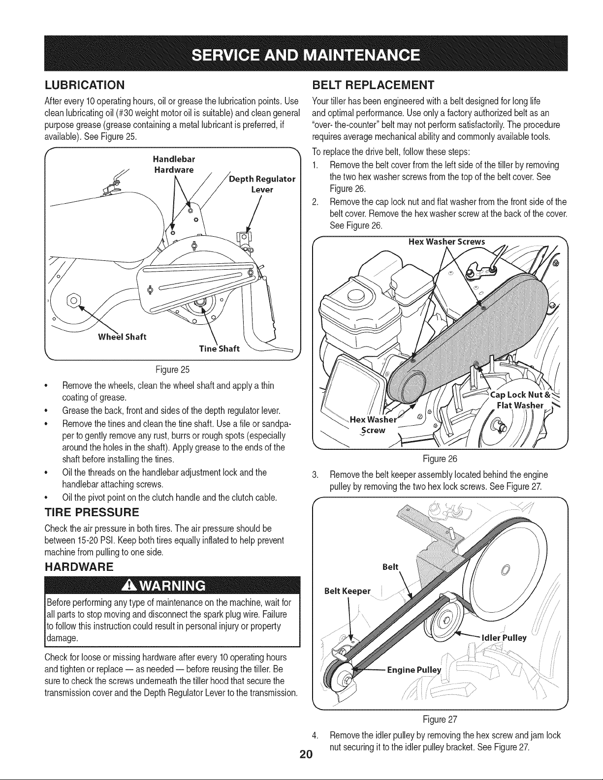
BELT REPLACEMENT
Yourtillerhasbeenengineeredwith a beltdesignedforlonglife
andoptimalperformance.Useonlya factoryauthorizedbeltasan
"over-the-counter"beltmaynotperformsatisfactorily.The procedure
requiresaveragemechanicalabilityandcommonlyavailabletools.
Toreplacethedrivebelt,followthesesteps:
1. RemovethebeltcoverfromtheIdt sideofthetillerbyremoving
thetwo hexwasherscrewsfromthetopof the beltcover.See
Figure26.
2. Removethe caplocknutandflatwasherfromthefrontsideofthe
beltcover.Removethehexwasherscrewat thebackofthe cover.
SeeFigure26.
Hex Washer Screws
Figure26
Removethe beltkeeperassemblylocatedbehindtheengine
pulleybyremovingthetwohex lockscrews.SeeFigure27.
Beforeperformingany typeofmaintenanceonthemachine,waitfor
all partsto stopmovinganddisconnectthesparkplugwire.Failure
tofollowthis instructioncouldresultinpersonalinjuryor property
damage.
Checkfor looseormissinghardwareafterevery10operatinghours
andtightenor replace-- as needed-- beforereusingthetiller.Be
sureto checkthe screwsunderneaththe tillerhoodthatsecurethe
transmissioncoverandthe DepthRegulatorLeverto thetransmission.
2O
v/*
Figure27
.
Removethe idlerpulleyby removingthehex screwandjamlock
nutsecuringittothe idlerpulleybracket.SeeFigure27.
5. Removetheoldbeltandinstallthenewbelt.Followtheinstruc-
tionsinreverseordertore-installthebeltkeeperandbeltcover.
SeeFigure27.
NOTE:Uponreassembly,makecertainthebeltisroutedovertheidler
pulleyandinsideofthebeltkeepersbytheenginepulley.
TINES
Thetineswillwearwithuseandshouldbeinspectedatthebeginningof
eachtillingseasonandafterevery30operatinghours.Thetinescanbe
replaced.RefertothePartsListsectionof thismanualforpartnumbers.
Tine Inspection
Withuse,thetineswill becomeshorter,narrowerandpointed.Badly
worntineswill resultina lossof tillingdepth,andreducedeffective-
nesswhenchoppingupandturningunderorganicmatter.
Removing/Installing a Tine Assembly
1. Removethetineshieldendcoversandsideshieldsbyremoving
thethree wingnutsoneach sidethatsecurethem.
2. Afineassemblyconsistsofa lefthandfineanda righthandfine.
NOTE:Thefineassemblymovesina counter-rotatingmotionwith
thesharpedgesof thetinespositionedtoenterthesoilfirstwhen
counter-rotating.Notethis positionof thetinesfor reinstallationof the
newfine assemblies.
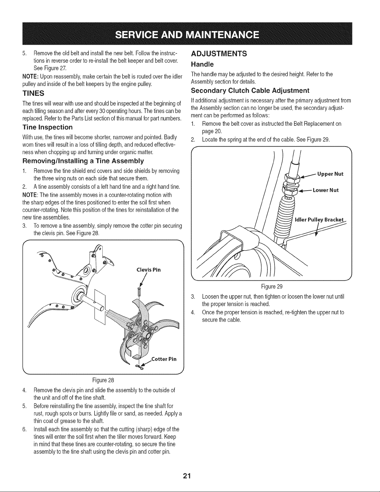
3. Toremoveafineassembly,simplyremovethecotterpin securing
theclevis pin.SeeFigure28.
ADJUSTMENTS
Handle
Thehandlemaybeadjustedto thedesiredheight.Refertothe
Assemblysectionfordetails.
Secondary Clutch Cable Adjustment
Ifadditionaladjustmentis necessaryaftertheprimaryadjustmentfrom
theAssemblysectioncannolongerbe used,the secondaryadjust-
mentcanbeperformedasfollows:
1. RemovethebeltcoverasinstructedtheBeltReplacementon
page20.
2. Locatethespringatthe endofthe cable.SeeFigure29.
Clevis Pin
/
C
Figure28
4. Removetheclevispinandslidetheassemblytotheoutsideof
theunitandoff ofthe fineshaft.
5. Beforereinstallingthe fineassembly,inspectthetineshaftfor
rust,roughspotsorburrs.Lightlyfileor sand,as needed.Applya
thincoatof greaseto theshaft.
6. Installeachtineassemblysothatthecutting(sharp)edgeof the
tineswillenterthesoil firstwhenthetiller movesforward.Keep
in mindthatthesetinesarecounter-rotating,sosecurethe fine
assemblytothe tineshaftusingthe clevispinandcotterpin.
Figure29
,
Loosentheuppernut,thentightenor loosenthelowernutuntil
thepropertensionis reached.
4.
Oncethepropertensionisreached,re-tightenthe uppernutto
securethecable.
21
idler Pulley Rod
Afterthebelttensionhasbeenadjusted,ifthebeltis excessivelystretched,
youmayneedtoadjusttheidlerpulleyrod.Thiscanbecheckedeasily.
Withtheengineoff andthe clutchcontrolbaildisengaged,shiftthe
gearselectionhandletoeachforwardmode.Ifthe indicatorbracket
touchestheidlerpulleyrodwiththeclutchcontrolbaildisengaged,
thenan adjustmentisnecessary.
1. Disconnectandgroundthesparkplugwire againsttheengine.
2. Removethebeltcoveras describedunderBeltReplacement
earlierin thissection.
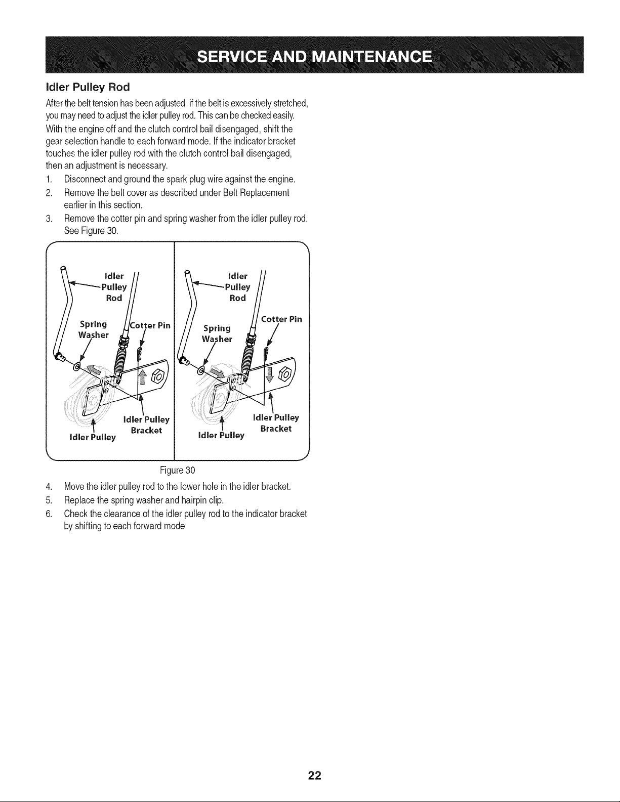
3. Removethecotterpin andspringwasherfromtheidlerpulleyrod.
SeeFigure30.
F
idler IRod t otter Pin
gROdllotter Pin
Washer _[ /
Spring /Washer
idlerPulley
idlerPulley
Bracket
idler Pulley
Bracket
Figure30
.
Movetheidlerpulleyrodtothe lowerholeinthe idlerbracket.
5.
Replacethespringwasherandhairpinclip.
6.
Checktheclearanceofthe idlerpulleyrodto theindicatorbracket
byshiftingtoeach forwardmode.
J
22
 Loading...