

Page 1
Operator's Manual
208cc Engine
Rear Tine Tiller
• SAFETY
• ASSEMBLY
• OPERATION
CAUTION: Before using
this products read this
manual and follow ail
• MAINTENANCE
• PARTS LIST
• ESPAÑOL
safety rules and operating
instructions.
Sears Brands Management Corporation, Hoffman Estates, IL 60179, U.S.A.
Visit our web site: www.craftsman.com
FORM NO. 769-05526A
12/02/2009
Page 2

TABLE OF CONTENTS
Warranty Statement....................................................Page 2
Safe Operation Practices...........................................Pages 3-6
Safety Labeis................................................................Page 7
Assembiy.......................................................................Pages 8-9
Operation
Service and Maintenance
Off-Season Storage....................................................Page 24
......................................................................
..........................................
Pages 10-17
Pages 18-23
Troubie Shooting...........................................................Page 25
Parts List.......................................................................................Page 26-31
Labei Map.......................................................................Page 32
Repair Protection Agreement.....................................Page 36
Españoi...........................................................................Page 37
Service Numbers...........................................................................Back Oover
WARRANT
CRAFTSMAN FULL WARRANTY
When operated and maintained according to all supplied instructions, it this Craftsman product fails due to a defect in material or workmanship
within two years from the date or purchase, call 1-800-4-MY-HOME® to arrange for free repair (or replacement it repair proves impossible).
This warranty applies for only 90 days from the date of purchase it this product is ever used for commercial or rental purposes.
This warranty covers ONLY defects in material and workmanship. Sears will NOT pay for:
• Expendable items that become worn during normal use, including but not limited to blades, tines, or belts.
• Tire or wheel replacement or repair resulting from normal wear, accident, or improper operation or maintenance.
• Repairs necessary because of operator abuse, including but not limited to damage caused by impacting objects that bend the frame or
motor crankshaft.
• Repairs necessary because of operator negligence, including but not limited to, electrical and mechanical damage caused by improper
storage, or failure to maintain the equipment according to the instructions contained in the operator’s manual.
• Repairs necessary due to improper fuel mixture, contaminated or stale fuel.
• Normal deterioration and wear of the exterior finishes, or product label replacement.
I
This warranty applies only while this product is within the United States.
This warranty gives you specific legal rights, and you may also have other rights which vary from state to state.
Sears, Roebuck and Co., FI off man Estates, IL 60179
PRODUCT SPECIFICATIONS
Engine Series: 208cc
Engine Oil Type: SAE 30
Engine Oil Capacity: 20 ounces
Fuel: Unleaded Gasoline
Spark Plug: Champion® RC-12YC
Spark Plug Gap: .030”
MODEL NUMBER
Model Number
Serial Number....................................................................
Date of Purchase...............................................................
...................................................................
Record the model number, serial number
and date of purchase above
§ Sears Brands, LLC
Page 3

SAFETY INSTRUCTIONS
J
A WARNING
This symbol points out important safety instructions which, it not
followed, could endanger the personal safety and/or property of
yourself and others. Read and follow all instructions in this manual
before attempting to operate this machine. Failure to comply with
these instructions may result in personal injury. When you see this
symbol, HEED ITS WARNING!
AWARNING
CALIFORNIA PROPOSITION 65
Engine Exhaust, some of its constituents, and certain vehicle
components contain or emit chemicals known to State of California
to cause cancer and birth defects or other reproductive harm. Bat
tery posts, terminals, and related accessories contain lead and lead
compounds, chemicals known to the State of California to cause
cancer and reproductive harm. Wash hands after handling.
TRAINING
• Read, understand, and follow all instructions on the machine and
in the manual(s) before attempting to assemble and operate.
Keep this manual in a safe place for future and regular reference
and for ordering replacement parts.
• Read the Operator’s Manual and follow all warnings and safety
instructions. Failure to do so can result in serious injury to the
operator and/or bystanders. For questions, call 1-800-4MY-HOME.
• Be familiar with all controls and their proper operation. Know how
to stop the machine and disengage them quickly.
• Never allow children under 14 years of age to operate this
machine. Children 14 and over should read and understand the
instructions and safe operation practices in this manual and on
the machine and be trained and supervised by an adult.
• Never allow adults to operate this machine without proper
instruction.
• Keep bystanders, pets, and children at least 75 feet from the
machine while it is in operation. Stop machine it anyone enters
the area.
• Never run an engine indoors or in a poorly ventilated area. Engine
exhaust contains carbon monoxide, an odorless and deadly gas.
A DANGER
This machine was built to be operated according to the safe opera
tion practices in this manual. As with any type of power equipment,
carelessness or error on the part of the operator can result in
serious injury. This machine is capable of amputating fingers, hands,
toes and feet and throwing debris. Failure to observe the following
safety instructions could result in serious injury or death.
___________
AWARNING
Your Responsibility—Restrict the use of this power machine to
persons who read, understand and follow the warnings and instruc
tions in this manual and on the machine.
SAVE THESE INSTRUCTIONS!
PREPARATION
• Thoroughly inspect the area where the equipment is to be used.
Remove all rocks, bottles, cans, or other foreign objects which
could be picked up or thrown and cause personal injury or
damage to the machine.
• Always wear safety glasses or safety goggles during operation
and while performing an adjustment or repair, to protect your
eyes. Thrown objects which ricochet can cause serious injury to
the eyes.
• Wear sturdy, rough-soled work shoes and close-fitting slacks and
shirts. Loose fitting clothes or jewelry can be caught in movable
parts. Never operate this machine in bare feet or sandals.
• Before starting, check all bolts and screws for proper tightness to
be sure the machine is in safe working condition. Also, visually
inspect machine for any damage at frequent intervals.
• Disengage clutch levers and shift (it provided) into neutral (“N”)
before starting the engine.
• Never leave this machine unattended with the engine running.
• Never attempt to make any adjustments while the engine is
running, except where specifically recommended in the operator's
manual.
• Maintain or replace safety and instructions labels, as necessary.
Page 4

SAFETY INSTRUCTION
I
Safe Handling of Gasoline;
To avoid personal injury or property damage use extreme care in
handling gasoline. Gasoline is extremely flammable and the vapors are
explosive. Serious personal injury can occur when gasoline is spilled
on yourself or your clothes which can ignite. Wash your skin and
change clothes immediately.
Use only an approved gasoline container.
Never fill containers inside a vehicle or on a truck or trailer bed
with a plastic liner. Always place containers on the ground away
from your vehicle before filling.
When practical, remove gas-powered equipment from the truck
or trailer and refuel it on the ground. If this is not possible, then
refuel such equipment on a trailer with a portable container, rather
than from a gasoline dispenser nozzle.
Keep the nozzle in contact with the rim of the fuel tank or
container opening at all times until fueling is complete. Do not use
a nozzle lock-open device.
Extinguish all cigarettes, cigars, pipes and other sources of
ignition.
Never fuel machine indoors.
Never remove gas cap or add fuel while the engine is hot or run
ning. Allow engine to cool at least two minutes before refueling.
Never over fill fuel tank. Fill tank to no more than
bottom of filler neck to allow space for fuel expansion.
Replace gasoline cap and tighten securely.
If gasoline is spilled, wipe it off the engine and equipment. Move
unit to another area. Wait 5 minutes before starting the engine.
To reduce tire hazards, keep machine free of grass, leaves, or
other debris build-up. Clean up oil or fuel spillage and remove any
fuel soaked debris.
Never store the machine or fuel container inside where there is an
open flame, spark or pilot light as on a water heater, space heater,
furnace, clothes dryer or other gas appliances.
'/2
inch below
OPERATION
Do not put hands or feet near rotating parts. Contact with the
rotating parts can amputate hands and feet.
Do not operate machine while under the influence of alcohol or
drugs.
Never operate this machine without good visibility or light. Always
be sure of your footing and keep a firm hold on the handles.
Keep bystanders away from the machine while it is in operation.
Stop the machine it anyone enters the area.
Be careful when tilling in hard ground. The tines may catch in the
ground and propel the tiller forward. If this occurs, let go of the
handle bars and do not restrain the machine.
Exercise extreme caution when operating on or crossing gravel
surfaces. Stay alert for hidden hazards or traffic. Do not carry
passengers.
Never operate the machine at high transport speeds on hard or
slippery surfaces.
Exercise caution to avoid slipping or falling.
Look down and behind and use care when in reverse or pulling
machine towards you.
Start the engine according to the instructions found in this manual
and keep feet well away from the tines at all times.
After striking a foreign object or if your machine should start mak
ing an unusual noise or vibration, immediately shut the engine off.
Disconnect the spark plug wire, ground it against the engine and
perform the following steps:
a. Inspect for damage.
b. Repair or replace any damaged parts.
c. Check for any loose parts and tighten to assure continued
safe operation.
Disengage all clutch levers (it fitted) and stop engine before you
leave the operating position (behind the handles). Wait until
the tines come to a complete stop before unclogging the tines,
making any adjustments, or inspections.
Never run an engine indoors or in a poorly ventilated area. Engine
exhaust contains carbon monoxide, an odorless and deadly gas.
Muffler and engine become hot and can cause a burn. Do not
touch.
Use caution when tilling near fences, buildings and underground
utilities. Rotating tines can cause property damage or personal
injury.
Do not overload machine capacity by attempting to till soil too
deep at too fast of a rate.
If the machine should start making an unusual noise or vibration,
stop the engine, disconnect the spark plug wire and ground it
against the engine. Inspect thoroughly for damage. Repair any
damage before starting and operating.
Keep all shields, guards, and safety devices in place and operat
ing properly.
Never pick up or carry machine while the engine is running.
Use only attachments and accessories approved by the manu
facturer as listed in the Parts List pages of this operator’s manual.
Failure to do so can result in personal injury.
If situations occur which are not covered in this manual, use care
and good judgement. Contact Customer Support at 1-800-4MY-
HOME for assistance and the name of the nearest service dealer
MAINTENANCE & STORAGE
Keep the machine, attachments and accessories in safe working
order.
Allow the machine to cool at least five minutes before storing.
Never tamper with safety devices. Check their proper operation
regularly.
Check bolts and screws tor proper tightness at frequent intervals
to keep the machine in safe working condition. Also, visually
inspect machine for any damage.
Before cleaning, repairing, or inspecting, stop the engine and
make certain the tines and all moving parts have stopped.
Disconnect the spark plug wire and ground it against the engine to
prevent unintended starting.
Page 5

SAFETY INSTRUCTIONS
J
• Do not change the engine governor settings or over-speed the
engine. The governor controls the maximum safe operating speed
of engine.
• Maintain or replace safety and instruction labels, as necessary.
• Follow this manual for safe loading, unloading, transporting, and
storage of this machine.
• Always refer to the operator’s manual for important details it the
machine is to be stored for an extended period.
• If the fuel tank has to be drained, do this outdoors.
• Observe proper disposal laws and regulations for gas, oil, etc. to
protect the environment.
• According to the Consumer Products Safety Commission (CPSC)
and the U.S. Environmental Protection Agency (EPA), this product
has an Average Useful Life of seven (7) years, or 130 hours of
operation. At the end of the Average Useful Life have the machine
inspected annually by an authorized service dealer to ensure that
all mechanical and safety systems are working properly and not
worn excessively. Failure to do so can result in accidents, injuries
or death.
DO NOT MODIFY ENGINE
To avoid serious injury or death, do not modify engine in any way.
Tampering with the governor setting can lead to a runaway engine and
cause it to operate at unsafe speeds. Never tamper with factory setting
of engine governor.
NOTICE REGARDING EMISSIONS
Engines which are certified to comply with California and federal
EPA emission regulations for SCRE (Small Cff Road Equipment) are
certified to operate on regular unleaded gasoline, and may include
the following emission control systems: Engine Modification (EM),
Cxidizing Catalyst (CC), Secondary Air Injection (SAI) and Three Way
Catalyst (TWC) it so equipped.
SPARK ARRESTOR
Awarning
This machine is equipped with an internal combustion engine and
should not be used on or near any unimproved forest-covered,
brushcovered or grass-covered land unless the engine's exhaust
system is equipped with a spark arrester meeting applicable local or
state laws (it any)
If a spark arrester Is used, it should be maintained in effective working
order by the operator. In the State of California the above is required
by law (Section 4442 of the California Public Resources Code). Cther
states may have similar laws. Federal laws apply on federal lands.
A spark arrester for the muffler is available through your nearest Sears
Parts and Repair Service Center.
Page 6

SAFETY INSTRUCTION
I
SAFETY SYMBOLS
This page depicts and describes safety symbols that may appear on this product. Read, understand, and follow all instructions on the machine
before attempting to assemble and operate.
Symbol Description
-
Y i
Ml
O
READ THE OPERATOR’S MANUAL(S)
Read, understand, and follow all instructions in the manual(s) before attempting to assemble and
operate
WARNING— ROTATING TINES
Do not put hands or feet near rotating parts. Contact with the rotating parts can amputate
hands and feet.
WARNING— ROTATING TINES
Do not put hands or feet near rotating parts. Contact with the rotating parts can amputate
hands and feet.
WARNING—GASOLINE IS FLAMMABLE
Allow the engine to cool at least two minutes before refueling.
WARNING— CARBON MONOXIDE
Never run an engine indoors orin a poorly ventilated area. Engine exhaust contains carbon
monoxide, an odorless and deadly gas.
WARNING— HOT SURFACE
Engine parts, especially the muffler, become extremely hot during operation. Allow engine
and muffler to cool before touching.
A
WARNING: Your Responsibility—Restrict the use of this power machine to persons who read, understand and follow the
warnings and instructions in this manual and on the machine.
SAVE THESE INSTRUaiONS!
A
Page 7
SAFETY LABELS
TO AVOID SERIOUS INJURY
Read the operator's manual.
Know location and functions of all controls.
Keep all safety devices and shields in place and working.
Never allow children or uninstructed adults to
operate tiller.
Shut off engine before unclogging tines or
making repairs.
KEEP AWAY FROM
ROTATING TINES.
ROTATING TINES
WILL CAUSE INJURY, the machine towards you.
Operation Of This Equipment May Create Sparks That Can Start Fires Around Dry Vegetation. A Spark
Arrestor May Be Required.The Operator Should Contact Local Fire Agencies For Laws Or Regulations
To Fire Prevention Requirements.
Keep bystanders away from machine.
Keep away from rotating parts.
Use extreme caution when reversing or pulling
I
Page 8
ASSEMBLY
IMPORTANT: This unit is shipped without gasoline or oil in the engine.
Be certain to service engine with gasoline and oil as instructed in the
Operation section of this manual before operating your machine.
NOTE: Reference to right and left hand side of the Tiller is observed
from the operating position.
OPENING CARTON
1. Remove all staples from around the bottom of the perimeter.
2. Remove the carton from the skid.
3. Remove all loose parts.
4. Remove loose packing material.
REMOVING UNIT FROM SKID
1. The tiller is heavy, do not attempt to remove it from the skid until
instructed to do so in these assembly steps.
2. Check carton thoroughly for any other loose parts.
LOOSE PARTS IN CARTON
• Handlebar Assembly
• Tiller
• Engine Oil
• Operator’s Manual
ATTACHING THE HANDLE ASSEMBLY
1. Install the handle onto the tiller using the hardware preinstalled
on the handle mounting brackets. This consists of a 5/16-18 x
3.00” hex bolt, a handle crank assembly, retainer bracket and two
5/16-18 flange lock nuts. Remove this hardware from the handle
mounting brackets on the tiller. Refer to Figure 1 inset.
2. Insert the handle into the handle mounting brackets, lining up the
pre-drilled holes. Insert the 5/16-18 x 3.00” hex bolt in the bottom
hole from the left hand side through to the other side. Place the
round hole end of the hex retainer bracket over the hex bolt and
secure loosely with a bell washer and 5/16-18 flange lock nut
removed earlier. Refer to Figure 1 inset.
NOTE: The bell washer should be positioned with the top of the bell
shape towards the hex nut which will create tension and further secure
the flange lock nut once tightened. Do not tighten this hardware at this
time.
3. Install the handle-crank adjustment rod into the top hole of the
mounting bracket from the left hand side of the handle assembly,
secure with the other flange lock nut previously removed. Fit
the hex end of the retainer bracket over the flange lock nut. See
Figure 1.
4. Tighten the hex bolt installed in Step 2 at this time. Be careful not
to overtighten this hardware.
5. With the handle in the desired position, tighten the handlecrank
adjustment rod at this time.
ATTACHING THE CABLES
1. Route the two cables along the handle assembly on the righthand
side.
2. Connect the reverse cable (Red) to the reverse cable control by
feeding the z-hook through the hole on the reverse cable control
from the inside towards the outside. See Figure 2.
3. Connect the forward drive cable (Black) to the clutch bail by
feeding the z-hook through the hole on the clutch bail from the
outside towards the inside. See Figure 2.
NOTE: Test the function of the reverse clutch by pulling the reverse
handle and releasing it. The handle should return to its neutral
position. If it doesn’t, contact Customer Support for assistance or the
nearest dealer.
To test the function of the forward drive bail, lift the bail to the handle
and release it. The bail should return to its neutral position. If it doesn’t,
contact Customer Support for assistance or the nearest dealer.
Page 9
ASSEMBLY
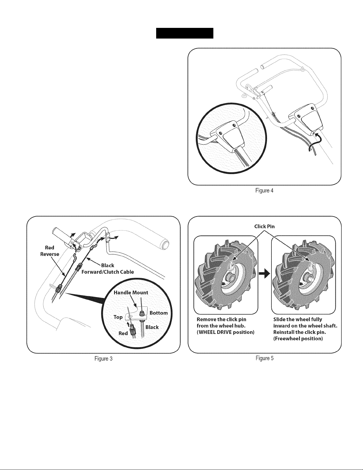
4. Snap the cable housing clips into the handle assembly cable
mount. The red clip (reverse cable) fits into the top position on the
handle assembly, while the black clip (forward/clutch cable) feeds
into the lower position on the handle assembly. See Figure 3.
5. Clip the cables into the cable guides located on the handle
assembly panel as seen in Figure 4.
MOVING THE TILLER OFF THE SKID
To roll the tiller off the shipping platform, put the wheels in freewheel, if
they are not already from the factory, as follows:
1. Place a sturdy block under the transmission to raise one wheel
about 1” off the ground. Remove the click pin from the wheel hub
and wheel shaft. See Figure 5.
Slide the wheel fully inward on the wheel shaft. Reinstall the click
2.
pin through the wheel shaft only (not through the wheel hub). See
Figure 5. The wheel should now spin freely (freewheel) on the
wheel shaft. Repeat with the other wheel.
Use the handlebar to lift and pull the tiller backwards to a flat
3.
area.
NOTE: Before starting the engine, the wheels must be placed in the
WHEEL DRIVE position (pins through wheel hubs and wheel shaft).
This procedure is described in the operation section under wheel drive
pins.
Page 10
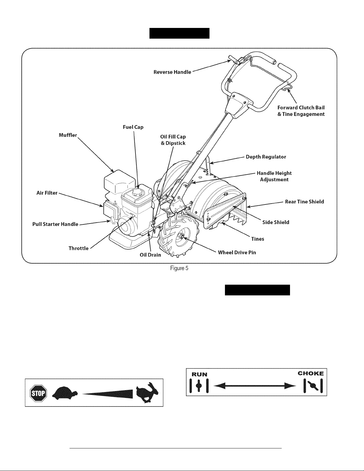
OPERATION
Now that you have set up your tiller tor operation, get aquainted with its
controls and features. These are described on the next two pages and
illustrated on this page. This knowledge will allow you to use your new
equipment to its fullest potential.
RECOIL STARTER HANDLE
This handle is used to start the engine. See Figure 5.
THROTTLE CONTROL
The throttle control is located on the front of the engine. It regulates the
spread of the engine and will shut off the engine when moved into the
STOP position. See Figure 5.
Meets ANSI Safety Standards
Craftsman Tillers conform to the safety standard of the American National Standards Institute (ANSI).
ik WARNING
The operation of any tiller can result in foreign objects being thrown
into the eyes, which can damage your eyes severely. Always wear the
safety glasses provided with this unit or eye shields before tilling and
while performing any adjustments or repairs.
CHOKE CONTROL
The choke control is activated by moving the lever to the CFIOKE
position. Activating the choke control closes the choke plate on the
carburetor and aids in starting the engine.
10
Page 11

OPERATION
J
AIR FILTER
The air filter is a device on the engine air intake that prevents dust and
dirt entering the engine. See Figure 5.
MUFFLER
Engine exhaust exits the engine via the muffler. See Figure 5.
OIL FILL CAP & DIPSTICK
Engine oil level can be checked and oil added through the oil fill. See
Figure 5.
NOTE: This unit was shipped WITHOUT oil In the engine. Oil Is
Included In the plastic bag packed with the manual In with the unit.
Add the oil as directed in the Gas & Oil Fill Up section. Check the oil
level before each operation to ensure adequate oil is in the engine.
For further instructions, refer to the steps in the Engine Maintenance
section of this manual.
REVERSE HANDLE
The Reverse Handle controls the reverse drive of the wheels and the
tines. See Figure 5.
FORWARD CLUTCH BAIL & TINE ENGAGE
MENT
The forward clutch ball controls the engagement of the forward drive of
the wheels and tines. See Figure 5.
REAR TINE SHIELD
The rear tine shield protects the operator from flying debris while also
smoothing out freshly tilled soil. See Figure 5.
SIDE SHIELD
The side shield is used to maintain clear even rows and may be
adjusted to one of five different positions. See Figure 5.
TINES
Your tiller’s tines are a series of hoes arranged on a revolving powerdriven shaft. See Figure 5.
WHEEL DRIVE PINS
Each wheel is equipped with a wheel drive click pin that secures the
wheel to the wheel shaft. The wheels can be positioned In either a
WHEEL DRIVE ora FREEWHEEL mode. See Figure 5.
OIL DRAIN
Removing the oil drain plug will drain the oil from the engine. See
Figure 5.
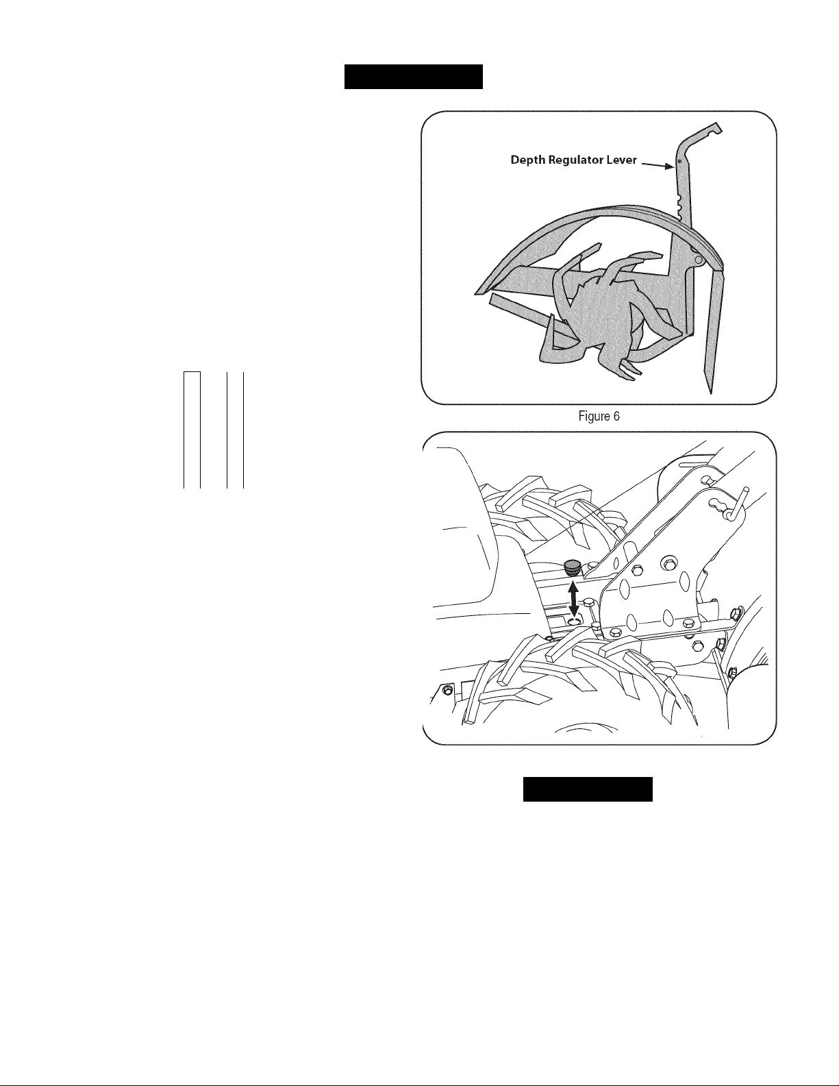
DEPTH REGULATOR LEVER
This lever controls the tilling depth of the tines. Pull the lever back and
slide It up or down to engage the notched height. See Figure 5.
HANDLEBAR HEIGHT ADJUSTMENT
The handlebar height is adjustable to three different settings. In
general, adjust the handlebars so they are at waist level when the tines
are 3-4” in the ground. See Figure 5.
11
Page 12
OPERATION
GAS AND OIL FILL-UP
Oil (one bottle shipped with unit)
First Time Use
1. Remove oil fill dipstick.
2. With the tiller on level ground, use a funnel to empty entire
contents of oil bottle provided into the engine.
3. Replace oil fill dipstick and tighten.
Subsequent Uses
Only use high quality detergent oil rated with API service classification
SF, SG, SH, SJ or higher. Select the oil's SAE viscosity grade accord
ing to the expected operating temperature. Follow the chart below.
A
i
Although multi-viscosity oils (5W30,10W30, etc.) improve starting
in cold weather, they will result in increased oil consumption when
used above 32°F. Check your engine oil level more frequently to avoid
possible engine damage from running low on oil.
1. Check the oil level making certain not to rub the dipstick along
the inside walls of the oil fill tube. This would result in a false
dipstick reading. Wipe dipstick clean with cloth. Replace dipstick
into the oil filler neck, but do not screw it in. Remove and check
oil level. Refill to FULL mark on dipstick, it necessary. Capacity is
approximately 20 oz. Cverfilling will cause the engine to smoke
profusely and will result in poor engine performance.
2. Replace oil fill dipstick and tighten.
3. Keep oil level at FULL. Running the engine with too little oil can
result in permanent engine damage.
A
0
o
CO
o
CO
1
o
0)
sz
(fi
Transmission/Gear Oil
First Time Use
1. With the tiller on level ground, pull the Depth Regulator Lever
back and then all the way up until the lowest notch in the lever is
engaged. See Figure 6.
2. Remove the oil fill plug from the transmission housing cover and
locate the main drive shaft situated inside the housing.
See Figure 7.
3. The gear oil level is correct it the gear oil is approximately halfway
up the side of the main drive shaft.
4. If the oil level is low, refer to the transmission gear oil under the
Maintenance Section.
Figure 7
Awarning
Use extreme care when handling gasoline. Gasoline is extremely
flammable and the vapors are explosive. Never fuel machine indoors
or while the engine is hot or running. Extinguish cigarettes, cigars,
pipes, and other sources of ignition.
Gasoline
1. Remove fuel cap from the fuel tank.
2. Make sure the container from which you will pour the gasoline is
clean and free from rust or foreign particles. Never use gasoline
that may be stale from long periods of storage in its container.
Gasoline that has been sitting tor any period longer than four
weeks should be considered stale.
3. Fill fuel tank with clean, fresh, unleaded regular gasoline only. Do
not use gasoline containing METHANOL. Replace fuel cap.
12
Page 13
OPERATIO
J
A CAUTION
Alcohol blended fuels (called gasohol or
can attract moisture which leads to separation and formation of acids
during storage. Acidic gas can damage the fuel system of an engine
while
in
storage.
____________________________________________
using
ethanol or methanol)
A CAUTION
To avoid engine problems, the fuel system should be emptied before
storage for 30 days or longer. Drain the gas tank, start the engine
and let it run until the fuel lines and carburetor are empty. Use fresh
fuel next season. See STORAGE Instructions for additional informa
tion.
A CAUTION
Never use engine or carburetor cleaner products in the fuel tank or
permanent damage may occur.
NOTE: Check the fuel level periodically to avoid running out of
gasoline while operating the tiller.
TO START ENGINE
1. Attach spark plug wire and rubber boot to spark plug.
2. Fill tank to no more than 1/2 inch below bottom of filler neck to
provide space for fuel expansion.
3. Put the wheels in the WHEEL DRIVE position.
4. Move the Depth Regulator Lever all the way down to the “trans
port” position, so that the tines clear the ground.
5. Release all of the controls on the tiller.
6.
Turn
the fuel shut-off valve to the ON position.
7. Move the choke lever on the engine to CHOKE N position. (A
warm engine may not require choking.) See Figure 8.
8. Move throttle control to START/RUN (Rabbit) JL m position. See
Figure 8.
9. Standing on the side of the unit, grasp starter handle and pull
rope out until you feel a drag.
10. Pull the rope with a rapid, continuous, full arm stroke. Keep a firm
grip on the starter handle. Let the rope rewind slowly.
11. Repeat, if necessary, until engine starts. When engine starts,
move choke control gradually toward the RUN 111 position..
12. If engine falters, move choke control back toward the CHOKE
N position and repeat steps 5 though 8.
13. ALWAYS keep the throttle control in the START/RUN (Rabbit
position when operating the tiller.
TO STOP ENGINE
1. To stop the wheels and tines, release the Forward Clutch Bail.
2. Move throttle control lever to slow (turtle) position.
Whenever possible, gradually reduce engine speed before
stopping engine.
3. Move throttle control lever to STOP or OFF position.
4.
Turn
the fuel shut-off valve to the OFF position.
5. Disconnect spark plug wire and ground it against the engine to
prevent accidental starting while the equipment is unattended.
AWARNING
Do not push down on the handlebars, especially in unfilled soil. This
could allow the tines to rapidly propel the tiller rearward, which can
result in loss of control, property damage, or personal injury.
TO ENGAGE DRIVE & TINES
1. For forward motion of the wheels and power to the tines pull the
Forward Clutch Bail up against the handlebar.
NOTE: In forward mode, the tines will rotate in reverse.
2. Walk slowly behind the tiller allowing It to move at its own pace
while keeping a secure grip on the handlebar with your elbows
flexed.
3. Release the bail to stop the rotation of the wheels and tines.
To move tiller in reverse: (Do not till in reverse)
a. Release the Forward Clutch Bail.
b. Lift the handlebar until the tines are off the ground.
c. Slowly pull back on the Reverse Lever, and carefully walk
backwards with the machine.
NOTE: In reverse mode, the tines will rotate forward.
d. If longer distances need to be covered in reverse, shut off the
Figure 8
13
Page 14
OPERATION
engine, then place the two wheels in FREEWHEEL.
TURNING THE TILLER
1. Practice turning the tiller in a level, open area. Be very careful to
keep your feet and legs away from the tines.
2. To begin a turn, lift the handlebars until the tines are out of the
ground and the engine and tines are balanced over the wheels.
3. With the tiller balanced, push sideways on the handlebar to steer
in the direction of the turn. After turning, slowly lower the tines into
Awarning
Be certain spark plug wire is disconnected and grounded against the
engine when performing any adjustments.
the soil to resume tilling.
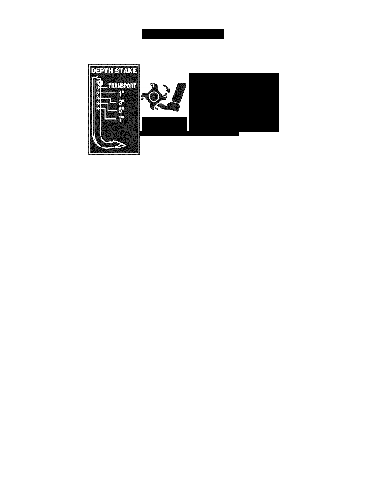
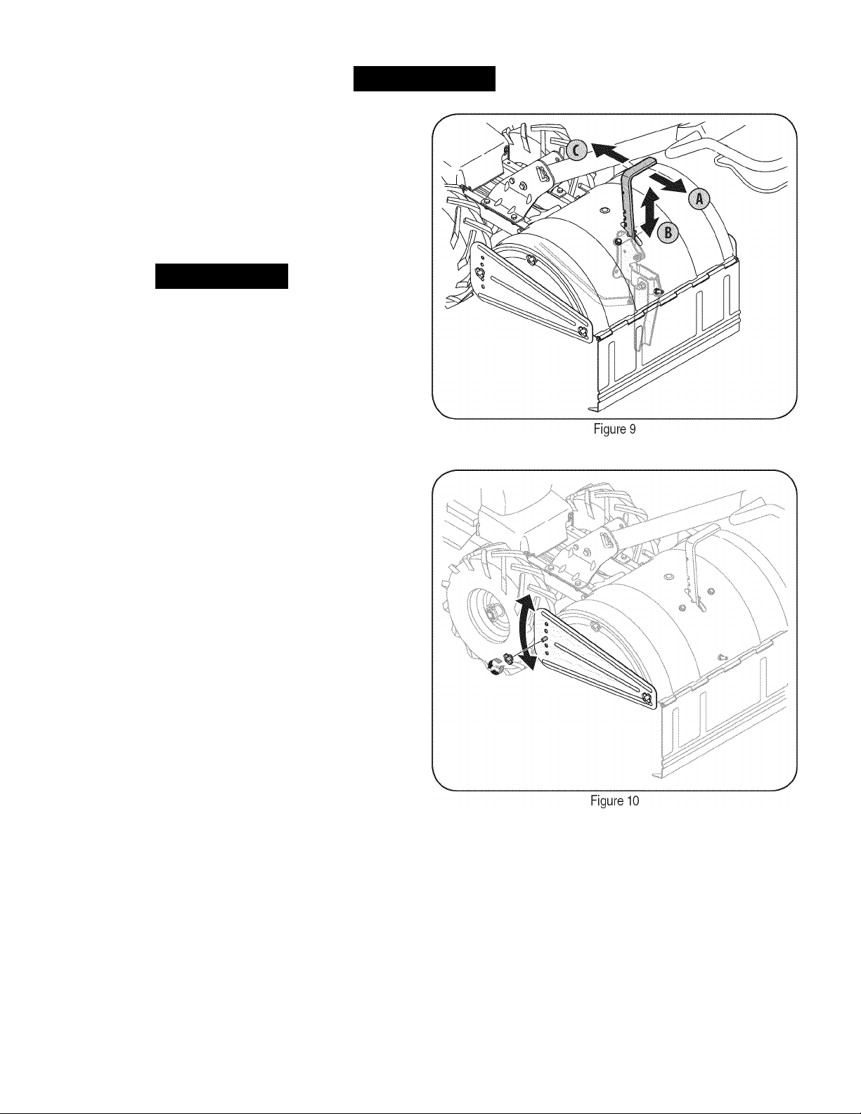
SETTING THE DEPTH
Tilling depth is controlled by the depth stake which can be adjusted to
five different settings. Adjust the side shields as you adjust the depth
stake.
• When using the tiller for the first time, use the second adjustment
hole from the top (1” of tilling depth).
• When breaking up sod and tor shallow cultivation, use the setting
which gives 1” of tilling depth (second hole from the top). Place
the side shields in their lowest position.
• For further depth, raise the depth stake and side shields and also
make one or two more passes over the area.
• When tilling loose soil, the depth stake may be raised to its
highest position (use bottom adjustment hole) to give the deepest
tilling depth. Raise the side shields to their highest position.
• To transport tiller, lower the depth stake (use top adjustment
hole).
To adjust the depth stake, pull back on the depth adjustment bracket
(A) and push up or down (B) until the bracket reaches the desired
position, then release the bracket (C). See Figure 9.
To adjust the side shields, remove the wing nuts. Move the side shield
14
Page 15
OPERATION
to the desired position and replace the wing nuts. Tighten securely.
See Figure 10.
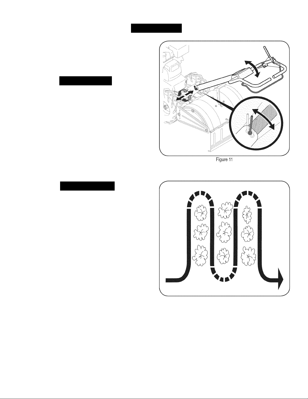
ADJUSTING THE HANDLE HEIGHT
The handle should be adjusted so that when the tiller is digging 3-4”
into the soil, the handle falls to about waste-high. To adjust handle,
AWARNING
Before clearing the tines by hand, stop the engine, allow all moving
parts to stop and disconnect the spark plug wire. Failure to follow this
warning could result in personal injury.
simply loosen the handle adjustment crank, move the handle to the
desired height and retighten the adjustment crank. See Figure 11.
CLEARING THE TINES
• The tines have a self-clearing action which eliminates most of the
tangling of debris. Flowever, occasionally dry grass, stringy stalks
or tough vines may become tangled. Follow these procedures to
help avoid tangling and to clear the tines, it necessary.
• To reduce tangling, set the depth regulator deep enough to get
maximum “chopping” action as the tines chop the material against
the ground. Also, try to till under crop residues or cover crops
while they are green, moist and tender.
AWARNING
Before tilling, contact your telephone or utilities company and inquire
it underground equipment or lines are used on your property. Do not
till near buried electric cables, telephone lines, pipes or hoses.
• While tilling, try swaying the handlebars from side to side (about
6” to 12”). This “fishtailing” action often clears the tines of debris.
TILLING TIPS & TECHNIQUES
Tilling Depth
• This is a CRT (counter-rotating tine) tiller. As the wheels pull
forward, the tines rotate backward. This creates an “uppercut”
tine action which digs deeply, uprooting soil and weeds. Don’t
overload the engine, but dig as deeply as possible on each pass
On later passes, the wheels may tend to spin in the soft dirt. Help
them along by lifting up slightly on the handlebar (one hand, palm
up, works most easily).
• Avoid the temptation to push down on the handlebars in an
attempt to force the tiller to dig deeper. Doing so takes the weight
off the powered wheels, causing them to lose traction. Without the
wheels to hold the tiller back, the tines will attempt to propel the
tiller backward, towards the operator.
• When cultivating (breaking up the surface soil around the plants
to destroy weeds. See Figure 12), adjust the tines to dig only 1”
to 2” deep. Using the shallow tilling depth helps prevent injury to
the plants whose roots often grow close to the surface. If needed,
lift up on the handlebars slightly to prevent the tines from digging
too deeply. (Cultivating on a regular basis not only eliminates
weeds, it also loosens and aerates the soil for better moisture
absorption and faster plant growth.) Watering the garden area a
few days prior to tilling will make tilling easier, as will letting the
Figure 12
15
Page 16
OPERATION
newly worked soil set for a day or two before making a final, deep
tilling pass.
Choosing the Correct Wheel & Tine Speeds
With experience, you will find the tilling depth and tilling speed
combination that is best for your garden. Set the engine throttle lever at
a speed to give the engine adequate power and yet allow it to operate
at the slowest possible speed until you have achieved the maximum
tilling depth you desire. Faster engine speeds may be desirable
when making final passes through the seedbed or when cultivating.
Selection of the correct engine speed, in relation to the tilling depth,
will ensure a sufficient power level to do the job without causing the
engine to labor.
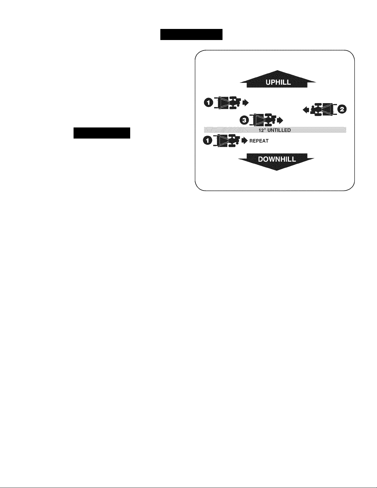
Suggested Tilling Patterns
• When preparing a seedbed, go over the same path twice in the
first row, then overlap one-half the tiller width on the rest of the
passes. See Figure 13.
• When finished in one direction, make a second pass at a right
angle. See Figure 14. Overlap each pass for the best results (in
very hard ground, it may take three or four passes to thoroughly
pulverize the soil.)
• If the garden size will not permit lengthwise and then crosswise
Figure 13
A
AWARNING
Do not operate the tiller on a slope too steep for safe operation. Till
slowly and be sure you have good footing. Never permit the tiller to
freewheel down slopes. Failure to follow this warning could result in
personal injury.
tilling, then overlap the first passes by one-half a tiller width, fol
lowed by successive passes at one-quarter width. See Figure 15.
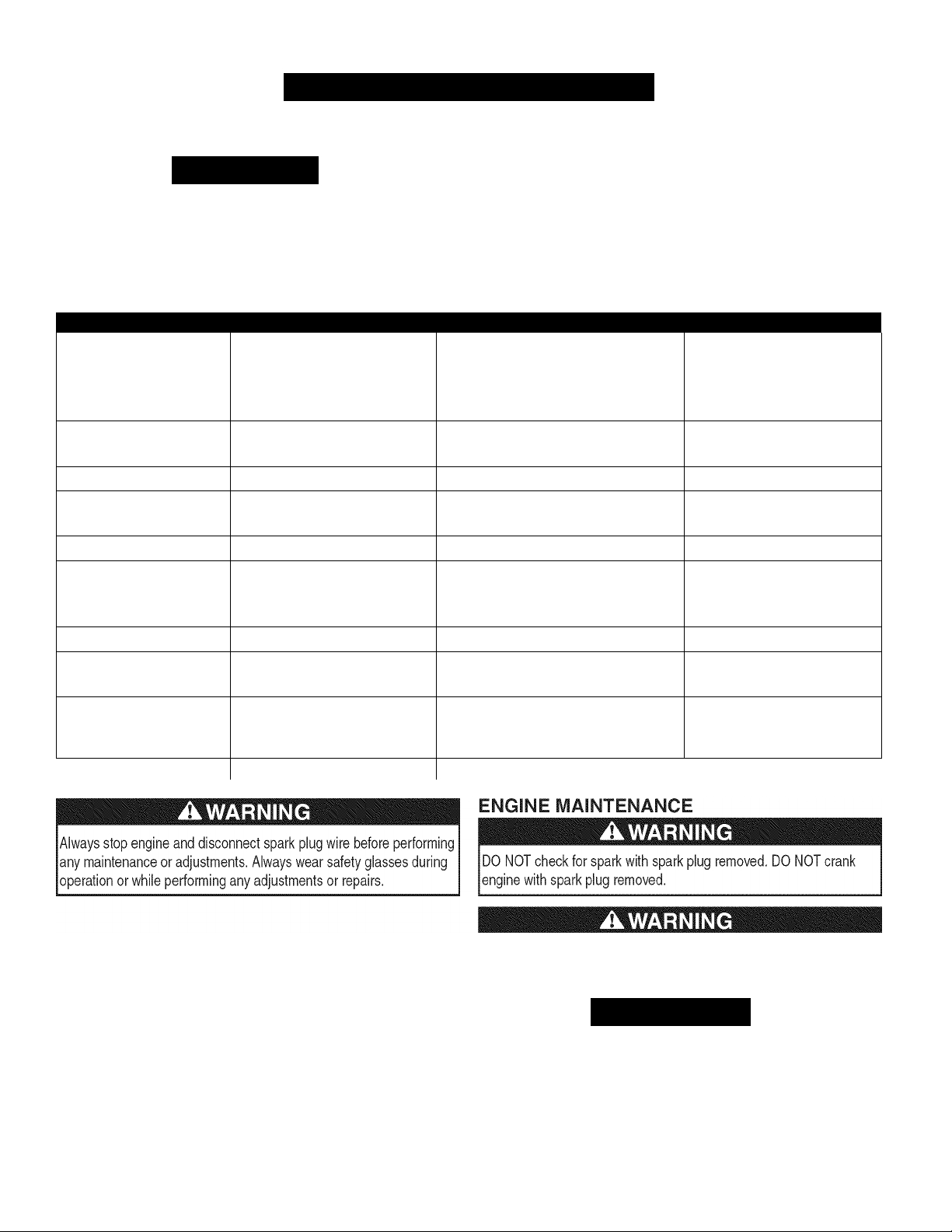
Tilling on a Slope
1. Till only on moderate slopes, never on steep ground where the
footing is difficult.
2. Tilling up and down slopes is recommended over terracing. Tilling
vertically on a slope allows maximum planting area and also
leaves room for cultivating.
NOTE: When tilling on slopes, be sure the correct oil level is main
tained in the engine (check every one-half hour of operation). The
incline of the slope will cause the oil to slant away from its normal
level and this can starve engine parts of required lubrication. Keep the
motor oil level at the full point at all times.
Tilling Up and Down a Slope
1. To keep soil erosion to a minimum, be sure to add enough organic
matter to the soil so that it has good moistureholding texture and
try to avoid leaving footprints or wheel marks.
2. When tilling vertically, try to make the first pass uphill as the tiller
digs more deeply going uphill than it does downhill. In soft soil or
weeds, you may have to lift the handlebars slightly while going up-
Figure 14
A
OB
m
16
B
Figure 15
Page 17
OPERATION
hill. When going downhill, overlap the first pass by about one-half
the width of the tiller.
Terrace Gardening
1. To create a terrace, start at the top of the slope and work down
Go back and forth across the first row. See Figure 16.
2. Each succeeding lower terrace is started by walking below the
terrace you are preparing. For added stability of the tiller, always
keep the uphill wheel in the soft, newly tilled soil. Do not till the
last 12” or more of the downhill outside edge of each terrace. This
untilled strip helps prevent the terraces from breaking apart and
Awarning
Loading and unloading the tiller into a vehicle is potentially hazard
ous and doing so is not recommended unless absolutely necessary,
as this could result in personal injury or property damage.
washing downhill. It also provides a walking path between the
rows.
Loading & Unloading the Tiller
If you must load or unload the tiller, follow the guidelines given below:
• Before loading or unloading the tiller, stop the engine, wait for all
parts to stop moving, disconnect the spark plug wire and let the
engine and muffler cool.
• Put the wheels in freewheel by putting the click pins through the
wheel shaft only (not through the wheel hub).
• The tiller is too heavy and bulky to be safely lifted by one person.
Two or more people should share the load.
• Use sturdy ramps and manually — with the engine shut off — roll
the tiller into and out of the vehicle. Two or more people are
needed to do this.
• The ramps must be strong enough to support the combined
weight of the tiller and any handlers. The ramps should provide
good traction to prevent slipping; they should also have side rails
to guide the tiller along the ramps; and they should have a locking
device to secure them to the vehicle.
• The handlers should wear sturdy footwear that will help to prevent
slipping.
• Position the loading vehicle so that the ramp angle is as flat
as possible (the less incline to the ramp, the better).
vehicle's engine off and apply the parking brake.
• When going up the ramps, stand in the normal operating position
and push the tiller ahead of you. Have a person at each side to
turn the wheels.
• When going down the ramps, walk backward with the tiller
following you. Keep alert tor any obstacles behind you. Position a
person at each wheel to control the speed of the tiller. Never go
down the ramps tiller-first, as the tiller could tip forward.
• Place wooden blocks on the downhill side of the wheels it you
need to stop the tiller from rolling down the ramp. Also, use the
blocks to temporarily keep the tiller in place on the ramps (if
necessary), and to chock the wheels in place after the tiller is in
the vehicle.
• After loading the tiller, prevent it from rolling by engaging the
wheels in the WHEEL DRIVE position. Chock the wheels with
Turn
the
Figure 16
17
Page 18
SERVICE AND MAINTENANCE
MAINTENANCE SCHEDULE
Awarning
Before performing any type of maintenance/service, disengage all
controls and stop the engine. Wait until all moving parts have come to
a complete stop. Disconnect spark plug wire and ground it against the
engine to prevent unintended starting. Always wear safety glasses during
operation or while performing any adjustments or repairs.
Interval
Each Use 1. Engine oil level 1. Check
2. Loose or missing hardware 2. Tighten or replace
3. Engine and around muffler 3. Clean
4. Air cleaner 4. Check
1st 2 hours 1. Drive belt tension 1. Check
2. Nuts and Bolts 2. Check
1st 5 hours 1. Engine oil 1. Change
Every 10 hours 1. Drive belt tension 1. Check
2. Unit 2. Lubricate
Every 25 hours 1. Spark plug 1. Check
Every 30 hours 1. Transmission oil level 1. Check
2. Tines for wear 2. Check
3. Tire pressure 3. Check
Annually or Every 50 hours 1.
Annually or Every 100 hours 1. Air cleaner 1. Change
Before Storage 1. Fuel system 1. Run engine until it stops from lack of
t Change oil every twenty five hours when operating engine under heavy load or in high temperatures
Engine oilf
2. Spark Plug 2. Change
Item
Follow the maintenance schedule given below. This chart describes
service guidelines only. Use the Service Log column to keep track of
completed maintenance tasks. To locate the nearest Sears Service
Center or to schedule service, simply contact Sears at
1-800-4-MY-HOME®.
Service Service Log
1. Change
fuel or add a gasoline additive to the
gas in the tank.
GENERAL RECOMMENDATIONS
• Always observe all safety rules found on product labels and in
this operator's manual when performing any maintenance. Safety
rules can be found on the product labels and in this Operator’s
Manual beginning on page 3.
• The warranty on this tiller does not cover items that have been
subjected to operator abuse or negligence. To receive full value
from warranty, operator must maintain the equipment as
instructed here.
• Some adjustments will have to be made periodically to maintain
your unit properly.
• Periodically check all fasteners and make sure these are tight.
If the engine has been running, the muffler will be very hot. Be careful
not to touch the muffler.
A CAUTION
The spark plug must be securely tightened. An improperly tightened
spark plug can become very hot and may damage the engine.
Checking the Spark Plug
To ensure proper engine operation, the spark plug must be properly
gapped and free of deposits. Check the spark plug every 25 hours and
replace it every 100 hours.
18
Page 19
SERVICE AND MAINTENANCE
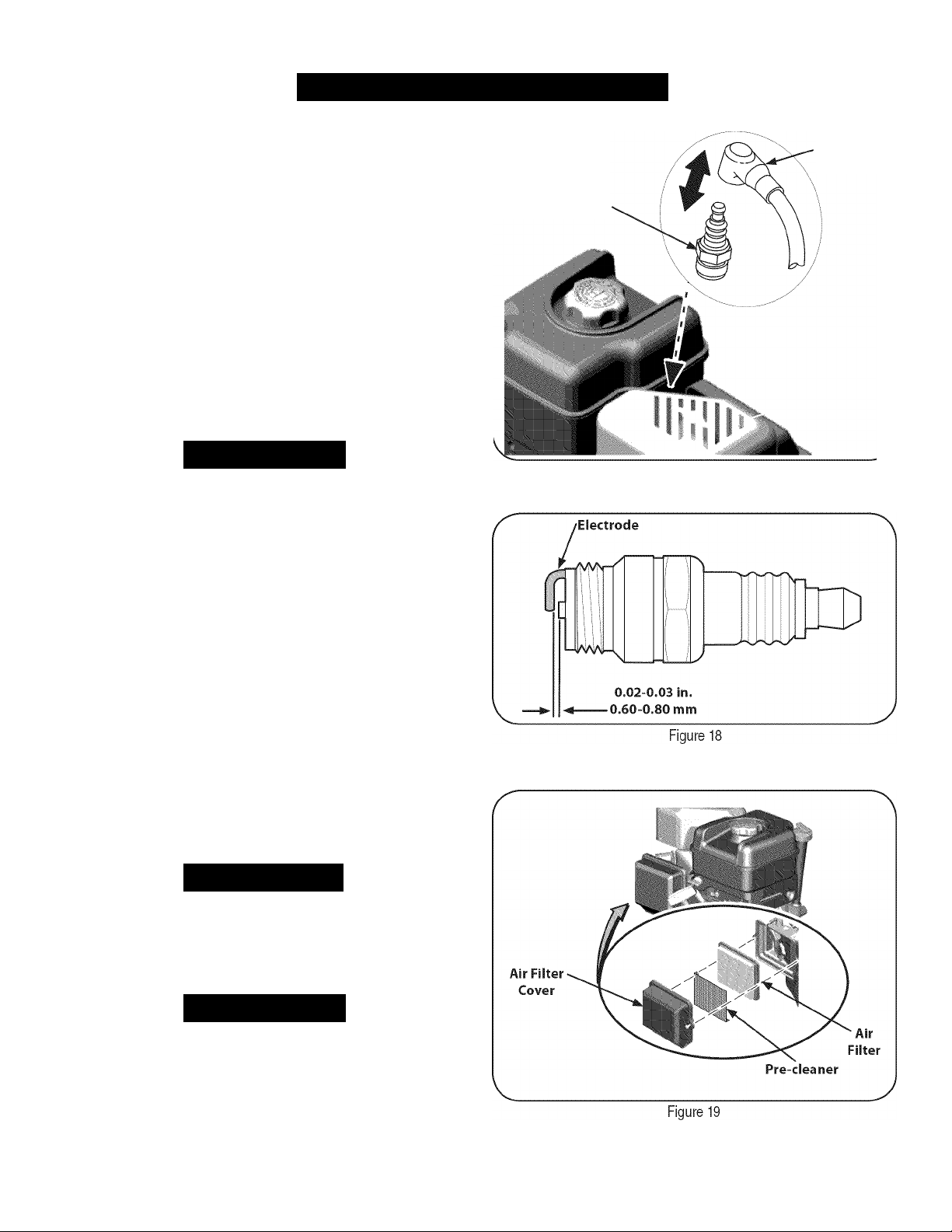
1. Remove the spark plug boot and use a spark plug wrench to
remove the plug. See Figure 17.
2. Visually inspect the spark plug. Discard the spark plug it there is
apparent wear, or if the insulator is cracked or chipped. Clean the
spark plug with a wire brush if it is to be reused.
3. Measure the plug gap with a feeler gauge. Correct as necessary
by bending side electrode. See Figure 18. The gap should be set
to 0.030 in.
4. Check that the spark plug washer is in good condition and thread
the spark plug in by hand to prevent crossthreading.
5. After the spark plug is seated, tighten with a spark plug wrench to
compress the washer.
NOTE: When installing a new spark plug, tighten 1/2
spark plug seats to compress the washer. When reinstalling a used
spark plug, tighten 1/8-1/4 turn after the spark plug seats to compress
the washer.
turn
after the
Spark Plug
Boot
Spark Plug
AWARNING
Never use gasoline or low flash point solvents for cleaning the air
cleaner element. A fire or explosion could result.
Servicing the Air Cleaner
The air cleaner prevents damaging dirt, dust, etc., from entering the
carburetor and being forced into the engine and is important to engine
life and performance. Never run the engine without an air cleaner
completely assembled. Check the air cleaner before each use.
Paper filters cannot be cleaned and must be replaced once a year
or every 100 operating hours; more often it used in extremely dusty
conditions.
1.
Loosen screws that hold the air filter cover. See Figure 19.
Open the cover and remove the pre-cleaner and air filter.
2.
Wash the pre-cleaner and allow to dry.
3.
4.
Discard old air filter.
5.
Install new air filter and washed pre-cleaner.
6.
Close the cover and tighten the screws.
NOTE: If the filter is torn or damaged in any way, replace it.
A CAUTION
Do not spray engine with water to clean because water could
contaminate fuel. Using a garden hose or pressure washing equip
ment can also force water into the muffler opening. Water that passes
through the muffler can enter the cylinder, causing damage.
Figure 17
AWARNING
Accumulation of debris around muffler could cause a fire. Inspect and
clean before every use.
Cleaning the Engine
If the engine has been running, allow it to cool for at least half an hour
before cleaning. Periodically remove dirt build-up from the engine.
Clean around the muffler. Clean with a brush or compressed air.
19
Page 20
SERVICE AND MAINTENANCE
Check Engine Oil
1. Check oil before each use. Stop engine and wait several minutes
before checking oil level. With the tiller on level ground, the oil
must be to FULL mark on dipstick.
2. Remove oil fill dipstick and wipe clean with cloth.
3. Replace dipstick into the oil filler neck, but do not screw it in.
Remove and check oil level. Level should be at FULL mark.
4. If needed, add oil slowly - recheck. Do not overfill.
5. Wipe dipstick clean, replace but do not tighten. Remove and
check oil level. Oil level should be at FULL line on dipstick.
6. Replace and tighten dipstick firmly before starting engine.
A CAUTION
DO NOT use non-detergent oil or 2-stroke engine oil. It could shorten
the engine’s service life.
Change Engine Oil
• SAE 30 is recommended for general, all temperature use. When
adding oil to the engine, refer to viscosity chart in the operation
section. Use a 4-stroke, or an equivalent high detergent, premium
quality motor oil certified to meet or exceed U.S. automobile
manufacturer’s requirements for service classification SF, SG, SH,
SJ or higher. Motor oils classified SF, SG, SH, SJ will show this
designation on the container.
• Change engine oil after the first five to eight hours of operation,
and every fifty hours or every season thereafter. Change oil every
twenty five hours when operating engine under heavy load or in
high temperatures.
Oil
Drain
Figure 20
4. Replace and tighten the oil drain end cap.
5. When engine is drained of all oil, place engine level. Refill with
approximately 20 oz. of fresh oil. Fill to FULL line on dipstick.
Do not overfill. Refer to Check Engine Oil in this SERVICE &
MAINTENANCE section.
6. Replace spark plug wire before starting.
AWARNING
Before tipping engine or equipment to drain oil, drain fuel from tank by
running engine until fuel tank is empty.
AWARNING
Used motor oil may cause skin cancer it repeatedly left in contact with
the skin for prolonged periods. Although this is unlikely unless you
handle used oil on a daily basis, it is still advisable to thoroughly wash
your hands with soap and water as soon as possible after handling
used oil.
To Drain Oil
1. Drain the fuel from the tank by running the engine until the fuel tank is
empty. Be sure fuel fill cap is secure.
2. With engine OFF but still warm, disconnect spark plug wire and
keep it away from spark plug.
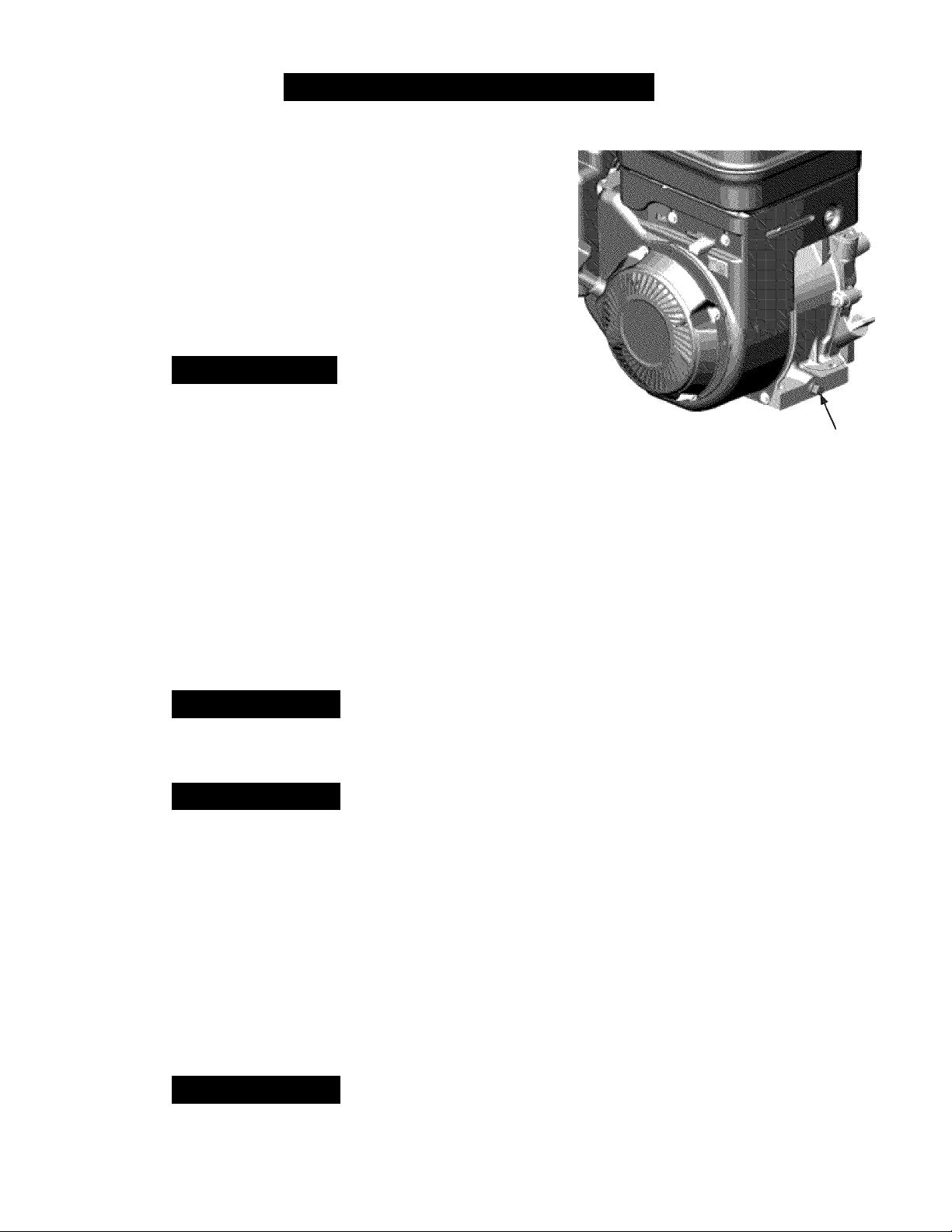
3. Remove oil drain end cap located at the base of the engine, and
drain oil into an appropriate receptacle. See Figure 20.
AWARNING
Used oil is a hazardous waste product. Dispose of used oil properly
Do not discard with household waste. Check with your local authori
ties or Sears Service Center for safe disposal/recycling facilities.
20
Page 21

SERVICE AND MAINTENANCE
Check Transmission Gear Oil
Check the transmission gear oil after every 30 hours of operation
or whenever you notice any oil leak. Operating the tiller when the
transmission is low on oil can result in severe damage.
To Check the Transmission Gear Oil Level:
1. Check the gear oil level when the transmission is cool. Gear oil
will expand in warm operating temperatures and this expansion
will provide an incorrect oil level reading.
2. With the tiller on level ground, pull the Depth Regulator Lever all
the way up.
3. Remove the oil fill plug from the transmission housing and look
inside the oil fill hole to locate the main drive shaft situated below
the hole. See Figure 21.
4. The gear oil level is correct it the gear oil is approximately halfway
up the side of the main drive shaft.
5. If the gear oil level is low, add gear oil as described next. If the
gear oil level is okay, securely replace the oil fill plug.
6. If adding only a few ounces of gear oil, use API rated GL-4 or
GL-5 gear oil having a viscosity of SAE 140, SAE 85W-140 or SAE
80W-90. If refilling an empty transmission, use only GL-4 gear oil
having a viscosity of SAE 85W-140 or SAE 140.
7. While checking frequently to avoid overfilling, slowly add gear oil
into the oil fill hole until it reaches the halfway point on the drive
shaft.
8. Securely replace the oil fill plug.
Change Transmission Gear Oil
The transmission gear oil does not need to be changed unless it has
been contaminated with dirt, sand or metal particles. See an autho
rized Sears Service Center to have the transmission gear oil changed
or to schedule service, simply contact Sears at 1-800-4-MY-HOME®.
LUBRICATION
After every 10 operating hours, oil or grease the lubrication points. Use
clean lubricating oil (#30 weight motor oil is suitable) and clean general
purpose grease (grease containing a metal lubricant is preferred, if
available). See Figure 22.
• Remove the wheels, clean the wheel shaft and apply a thin
coating of grease.
• Grease the back, front and sides of the depth regulator lever.
• Remove the tines and clean the tine shaft. Use a file or sandpa
per to gently remove any rust, burrs or rough spots (especially
around the holes in the shaft). Apply grease to the ends of the
shaft before installing the tines.
• Oil the threads on the handlebar height adjustment screws and
the handlebar attaching screws.
TIRE PRESSURE
Check the air pressure in both tires. The air pressure should be betwen
15-20 PSI. Keep both tires equally inflated to help prevent machine
from pulling to one side.
HARDWARE
Check for loose or missing hardware after every 10 operating hours
and tighten or replace — as needed — before reusing the tiller. Be
sure to check the screws underneath the tiller hood that secure the
transmission cover and the Depth Regulator Lever to the transmission.
21
Page 22

SERVICE AND MAINTENANCE
Awarning
Before performing any type of maintenance on the machine, wait for
all parts to stop moving and disconnect the spark plug wire. Failure
to follow this instruction could result in personal injury or property
damage.
BELT REPLACEMENT
If the drive belt or reverse belt needs to be replaced, it is best to
replace both belts
belt as an “over- the-counter” belt may not perform satisfactorily.
The procedure requires average mechanical ability and commonly
available tools.
To replace the Drive and Reverse belts, follow these steps:
1. Make sure the tiller is on a flat surface, with the engine turned
off and the spark plug wire unplugged and grounded to prevent
unintended firing of the engine.
2. Remove the belt cover by first removing the two 1/4-20 self
tapping hex screws. See Figure 23. Lift the belt cover up and
away from the tiller and set in a safe location until reinstallation.
3. Remove the four 1/4-20 self-tapping hex screws that secure the
pulley shield to the frame and remove the pulley shield and set
aside in a safe location until reinstallation. See Figure 24.
4. Remove the idler bracket extension spring. See Figure 25. It is
recommended to use a pair of needle-nosed pliers, and grab the
spring by the end that hooks over the frame. Simply grab it and
pull it away from the frame, then up wards and carefully relieve
the tension of the spring.
5. Remove the idler pulley bracket by removing the 5/16-24 hex
head screw, flat washer and lock washer. See Figure 26.
NOTE: It will be necessary to remove the belt from around the idler
pulley by working it off the pulley and from underneath each belt
keeper.
at
the same time. Use only a factory authorized
Remove the
belt from the
idler pulley
by working it
under the belt
keepers.
Figure 23 Figure 26
Remove the
idler pulley
bracket by
removing the
hex head screw,
fiat and lock
washers
Page 23

SERVICE AND MAINTENANCE
Remove the hex bolts securing the transmission drive pulley, then
remove the pulley along with the two belts. See Figure 27.
Replace the old belts with the new belts in the same order they
7.
were removed. The longer belt (1916658) belongs closer to the
engine (V-side out), with the shorter belt (1916657) positioned
closer to the tines.
8. Reinstall the transmission drive pulley with the new belts.
9. Reassemble the tiller in the reverse order in which it was disas
sembled.
IMPORTANT: When reinstalling the belt cover, be sure to engage
the bail and hold it so that the drive belt is tight before attempting to
reinstall the belt cover. This will enable the belt to fall under the belt
keeping mechanism built into the belt cover. Failure to do so could
damage the belt and/or belt cover.
TINES
The tines will wear with use and should be inspected at the beginning
of each tilling season and after every 30 operating hours. The tines
can be replaced. Refer to the Parts List section of this manual for part
numbers.
Tine Inspection
With use, the tines will become shorter, narrower and pointed. Badly
worn tines will result in a loss of tilling depth, and reduced effective
ness when chopping up and turning under organic matter.
Removing/lnstalling a Tine Assembly
1. Remove the tine shield end covers and side shields by removing
the three wing nuts on each side that secure them.
2. A tine assembly consists of a left hand tine and a right hand tine.
NOTE: The tine assembly moves in a counter-rotating motion with
the sharp edges of the tines positioned to enter the soil first when
counter-rotating. Note this position of the tines for reinstallation of the
new tine assemblies.
3. To remove a tine assembly, simply remove the cotter pin securing
the clevis pin. See Figure 28.
4. Remove the clevis pin and slide the assembly to the outside of
the unit and off of the tine shaft.
5. Before reinstalling the tine assembly, inspect the tine shaft tor
rust, rough spots or burrs. Lightly file or sand, as needed. Apply a
thin coat of grease to the shaft.
6. Install each tine assembly so that the cutting (sharp) edge of the
tines will enter the soil first when the tiller moves forward. Keep
in mind that these tines are counter-rotating, so secure the tine
assembly to the tine shaft using the clevis pin and cotter pin.
23
Page 24

OFF-SEASON STORAG
AWARNING
Never store tiller with fuel in tank indoors or in poorly ventilated areas
where fuel fumes may reach an open flame, spark, or pilot light as on
a furnace, water heater, clothes dryer, or gas appliance.
I
AWARNING
[ Never leave engine unattended while
PREPARING THE ENGINE
Engines stored between 30 and 90 days need to be treated with a
gasoline stabilizer and engines stored over 90 days need to be drained
of fuel to prevent deterioration and gum from forming in fuel system or
on essential carburetor parts. If the gasoline in your engine deterio
rates during storage, you may need to have the carburetor, and other
fuel system components, serviced or replaced.
1. Remove all fuel from tank by running engine until it stops from
lack of fuel.
2. Change the oil. See Change Engine Oil in SERVICE AND
MAINTENANCE section.
3. Remove spark plug and pour about a 1/2 ounce of engine oil into
the cylinder. Replace spark plug and crank it slowly to distribute
oil.
4. Clean debris from around the engine and the muffler. Touch up
any damaged paint, and coat other areas that may rust with a light
film of oil.
5. Store in a clean, dry and well ventilated area away from any ap
pliance that operates with a flame or pilot light, such as a furnace,
water heater, or clothes dryer. Also avoid any area with a spark
producing electric motor, or where power tools are operated.
6. If possible, also avoid storage areas with high humidity, because
that promotes rust and corrosion.
7. Keep the engine level in storage. Tilting can cause fuel or oil
leakage.
it is
running.
_________________
PREPARING THE TILLER
When the tiller won’t be used for an extended period, prepare it for
|
storage as follows:
1. Clean the tiller and engine.
2. Follow the lubrication recommendations and check for loose parts
and hardware.
3. Store the tiller in a clean, dry area.
4. Never store the tiller with fuel in the fuel tank in an enclosed area
where gas fumes could reach an open flame or spark, or where
ignition sources are present (space heaters, hot water heaters,
furnaces, etc.).
24
Page 25

TROUBLESHOOTING
Awarning
Before performing any type of maintenance/service, disengage all controls and stop the engine. Wait until all
moving parts have come to a complete stop. Disconnect spark plug wire and ground it against the engine to prevent
unintended starting. Always wear safety glasses during operation or while performing any adjustments or repairs.
I
Problem
Engine fails to start 1. Spark plug wire disconnected.
2. Engine Throttle Control Lever Incorrectly set.
3. Fuel tank empty or stale fuel.
4. Dirty air filter.
5. Defective or Incorrectly gapped spark plug.
6. MIsadjusted throttle control.
7. Dirt or water In fuel tank.
Engine runs erratically 1. Defective or incorrectly gapped spark plug.
2. Dirty air fllter(s).
3. Carburetor out of adjustment.
4. Stale gasoline.
5. Dirt or water In fuel tank.
6. Engine cooling system clogged.
Engine overheats 1. Engine cooling system clogged.
2. Carburetor out of adjustment.
3. Oil level Is low.
Engine does
Wheels/Tines will not turn 1. Improper use of controls.
Tines turn, but wheels don’t 1. Wheel Drive Pins not In WHEEL DRIVE.
Wheels
Poor tilling performance 1. Worn tines.
not
shut off 1. MIsadjusted throttle control or Ignition switch. 1. Contact your Sears Parts & Repair Center.
2. Worn, broken, or misadjusted drive belt(s).
3. Internal transmission wear or damage.
4. Bolt loose In transmission pulley.
2. Bolt loose in transmission pulley.
3. Internal transmission wear or damage.
turn,
but tines don’t 1. Tine holder mounting hardware missing.
2. Bolt loose in transmission pulley.
3. Internal transmission wear or damage.
2. Improper Depth Regulator setting.
3. Incorrect throttle setting.
4. Forward Drive Belt slipping.
Cause Remedy
1. Reconnect wire.
2. Put lever In START position.
3. Fill tank with clean, fresh gasoline.
4. Clean or replace filter.
5. Clean, adjust gap, or replace.
6. Contact your Sears Parts & Repair Center.
7. Contact your Sears Parts & Repair Center.
1. Clean, adjust gap, or replace.
2. Clean or replace.
3. Contact your Sears Parts & Repair Center.
4. Replace with fresh gasoline.
5. Contact your Sears Parts & Repair Center.
6. Clean air cooling system.
1. Clean air cooling area.
2. Contact your Sears Parts & Repair Center.
3. Check oil level.
1. Review Operation section.
2. Replace or adjust belts.
3. Contact your Sears Parts & Repair Center.
4. Tighten bolt.
1. Inserts Drive Pins properly.
2. Tighten bolt.
3. Contact your Sears Parts & Repair Center.
1. Replace hardware.
2. Tighten bolt.
3. Contact your Sears Parts & Repair Center.
1. Replace Tines.
1. See “Tilling Tips & Techniques.”
1. See Service & Maintenance Section.
1. See Service & Maintenance Section.
NEED MORE HELP?
' Find this and all your other product manuals online.
' Get answers from our team of home experts.
' Get a personalized maintenance plan for your home.
' Find information and tools to help with home projects.
25
Page 26

Craftsman Tiller — Model No. 247.29931
PARTS LIS
J
26
Page 27

Craftsman Tiller — Model No. 247.29931
Ref. No. Part No. Description
1 686-0044B-0721 End Cover Assembiy
2 710-0597 Hex Head Screw, 1/4-20 x 1
3 710-0604A Seif Tapping Screw, 5/16-18 x .625
4 710-1238 Hex Head Screw, 5/16-18 x .875
5 710-3008 Hex Head Screw, 5/16-18 x .75
6 712-04063 Nyion Hex Lock Nut, 5/16-18
7 712-04064 Nyion Hex Lock Nut, 1/4-20
8 712-04065 Flange Lock Nut, 3/8-16
9 712-0421 Wing Nut, 5/16-18
10 715-0108 Spirol Pin
11 926-0106 Cap Nut, 1/4 Rod
12 731-05512 Hole Plug
13 732-04320 Torsion Spring
14 738-04320 Shoulder Screw, .405 x .435 5/16-18
15 938-0533 Shoulder Screw, .498 x 1.635
16 938-0849 Stop Screw
17 747-0432 Tiller Flap Rod
18 750-05349 Spacer
19 786-0090A-0721 Side Shield
20 786-0113A-0721 Rear Tine Shield
21 786-04092-0721 Reverse Stop Arm
22. 786-04104-0721 Drag Bar
23 786-04352A-0721 Tine Shield Mounting Bracket
24 786-04355A-0721 Tine Shield
25 786-04356-0721 Adjustable Depth Bar
26 786-04363-0721 Tail Bracket, LH
I
PARTS LIS
J
Ref. No. Part No. Description
27 786-04364-0721 Tail Bracket, RH
28 649-04054-0721 Upper Handle Assembly
29 686-04098-0721 Reverse Handle Assembly
30 710-0189 Hex Head Screw, 5/16-18 x 3.00
31 710-0599 Self-Tapping Screw, 1/4-20 x 1/2
32 720-0270A Reverse Handle Grip
33 720-0278A Foam Handle Grip
34 726-0135 Cap Nut, .3125 dia.
35 731-06253A Handle Cover
36 735-04105 Plug End
37 736-0242 Bell Washer, .340 x .872 x .060
38 946-04504 Reverse Cable
39 946-04506 Forward Cable
40 747-04789-0637 Clutch Bail
41 750-0885A Spacer, .322 x .625 x 2.00
42 786-0340A Handle Crank
43 786-04344-0721 Handle Bracket, RH
44 786-04345-0721 Handle Bracket, LH
45 786-04358 Retainer Nut Bracket
46 786-04360-0721 Front Bumper
47 731-06529 Belt Cover
48 736-0173 Flat Washer, .28 x .74 x .063
49 710-0502A SEMS Screw, 3/8-16
50 710-0805 Hex Head Screw, 5/16-18 x 1.50
51 736-04193 Bell Washer, .827 x .331 x .098
52 710-1307 Stub, 5/16-18 X .75
Page 28

Craftsman Tiller — Model No. 247.29931
PARTS LIS
J
28
Page 29

Craftsman Tiller — Model No. 247.29931
I
PARTS LIS
J
Ref. No. Part No. Description
1 634-04652 Complete WhI. Ass., 13x5x6(6, C)
2 714-0143A Click Pin
3 684-04168 Idler Pulley Assembly
4 710-0331 Hex Head Screw, 3/8-24 x 2.25
5 710-0170 Hex Head Screw, 5/16-24 x .625
6 710-0599 Self Tapping Screw, 1/4-20 x .500
7 710-0606 Hex Head Screw, 1/4-20 x 1.50
8 710-0672 Hex Head Screw, 5/16-18 x 1.25
9 710-1880 Hex Head Screw, 5/16-18 x .75, Patch
10 710-3008 Hex Head Screw, 5/16-18 x .75, STD
11 712-04064 Nylon Hex Lock Nut, 1/4-20
12 712-0700 Nut, 9/16-18, Flange Lock
13 718-04407 Hub, 5/8 Spline
14 732-04085 Extension Spring, .480 OD X 5.00 LG
15 732-04276A Extension Spring, LT5 PTO
16 936-0119 Lock Washer, 5/16
17 736-0173 Washer, .28 x .74 x .063
18 714-04043 Internal Cotter Pin
19 736-0343 Flat Washer, .330 X 1.25 X .120
20 936-0452 Bell Washer, .396 x 1.140 x .095
21 736-3092 Flat Washer, .265 x 1.0 x .030
Ref. No. Part No. Description
22 738-04425 Shoulder Screw, .342 x .335 1/4-28
23 748-04087A Pivot Idler Spacer
24 750-04571 Shoulder Spacer, .260 x .785 x .538
25 750-04907 Pivot Idler Spacer
26 1916657 V-Belt,4Lx 25.375 Long
27 1916658 V-Belt,3Lx 29.125 Long
28 756-04198A Engine Pulley
29 756-04355 Transmission Pulley
30 756-0625 Cable Roller
31 786-04312 Idler Bracket, Forward
32 786-04343-0721 Cover Plate
33 786-04346 Idler Bracket, Reverse
34 786-04416-0721 Mounting Frame, RH
35 786-04415A-0721 Mounting Frame, LH
36 786-04357-0721 Pulley Bracket
37 786-04371-0721 Pulley Shield
38 642-04071-0721 Tine Assembly, LH
39 642-04072-0721 Tine Assembly, RH
40 911-0415 Clevis Pin, .375 x 1.75
41 918-04815A Transmission Assembly
29
Page 30

Craftsman Tiller — Model No. 247.29931
12
PARTS LIS
J
30
Page 31

Craftsman Tiller — Model No. 247.29931
Ref. No. Part No. Description
918-04815A Transmission Assembly
1 919-04184A Housing, Transmission
2 710-3008 Hex Screw, 5/16-18, .75, Gr5
3 911-04844 Shaft, Tiller
4 911-04854 Shaft, Wheel
5 911-05028 Shaft, Worm
6 714-04059 Key, Hi Pro .25x 1.062
7 716-0204 Retaining Ring
8 716-04102 Retaining Ring, Int
9 917-04380 Worm Gear, 61t, RH
10 917-04381 Worm Gear, 30t, LH
11 918-04435 Bearing Cover
12 921-04030 Seal, Oil, .750 Shaft x 1.783 Bore
13 921-04229 Gasket, Gear Housing
14 721-04232 Seal, Oil, 1.00 Shaft x 2.00 Bore
15 721-04271 Rubber Plug, Oil
16 732-0614 Wire Ring
17 736-04305 * Washer, Flat, 1.50x 1.75X.062
736-04306 * Washer, Flat, 1.50x 1.75X.005
736-04307 * Washer, Flat, 1.50 x 1.75 x .03
736-04308 * Washer, Flat, 1.50x 1.75X.010
18 736-0745 Washer, Flat, 1.01 Ox 1.56X.060
19 941-04298 Cone Bearing
20 941-04299 Bearing Cup
21 741-3114 Ball Bearing
22 786-04366 Cover, Transmission
23 786-04392 Cover, Transmission
* The flat washers listed
in allowable end play on
I
PARTS LIS
J
are used as required to obtain .005 to .015
the drive shaft.
31
Page 32

Craftsman Tiller Model No. 247.29931
Parts Li
J
777S33496
Keep all safety devices and shields in place and vrarking.
Never allow children or uninstructed adults to
operate tiller.
Shut off engine before unclogging tines or
making repairs.
Keep bystanders away from machine.
Keep away from rotating parts.
Operation Of This Equipment May Create Sparks That Can Start Fires Around Dry Vegetation. A Spark
Arrestor May Be Required. The Operator Should Contact Local Fire Agencies For Laws Or Regulations
To Fire Prevention Requirements.
777D14197
777I22969
777X43688
iiiof
USE E85 OR FUEL'
CONTAINING MORE'
I THAN 10% ETHANOL I
M.
777I20358
777I22968
' TILL "
COUNTER
ROTATING
TIN
ii
WHEELS
FORWARD
Page 33

NOTE
J
Page 34

(This page applicable in the U.S.A. and Canada only.)
Sears, Roebuck and Co., U.S.A. (Sears), the California Air Resources Board (CARB)
and the United States Environmental Protection Agency (U.S. EPA)
Emission Control System Warranty Statement (Owner’s Defect Warranty Rights and Obligations)
EMISSION CONTROL WARRANTY COVERAGE IS APPLICABLE TO CERTI- YEAR 1997 AND LATER ENGINES WHICH ARE PURCHASED AND USED
PIED ENGINES PURCHASED IN CALIFORNIA IN 1995 AND THEREAF- ELSEWHERE IN THE UNITED STATES (AND AFTER JANUARY 1,2001 IN
TER, WHICH ARE USED IN CALIFORNIA, AND TO CERTIFIED MODEL CANADA).
California and United States Emission Control Defects Warranty Statement
The California Air Resources Board (CARB), U.S. EPA and Sears are pleased engine for the periods of time listed below, provided there has been no abuse,
to explain the Emission Control System Warranty on your model year 2000 and neglect or improper maintenance of your small off-road engine. Your emislater small off-road engine (SORE). In California, new small off-road engines
must be designed, built and equipped to meet the State’s stringent anti-smog
standards. Elsewhere in the United States, new non-road, spark-ignition
engines certified for model year 1997 and later must meet similar standards set
forth by the U.S. EPA. Sears must warrant the emission control system on your
sion control system includes parts such as the carburetor, air cleaner, ignition
system, muffler and catalytic converter. Also included may be connectors and
other emission related assemblies. Where a warrantable condition exists. Sears
will repair your small off-road engine at no cost to you including diagnosis, parts
and labor.
Sears Emission Control Defects Warranty Coverage
Small off-road engines are warranted relative to emission control parts defects part on your engine is defective, the part will be repaired or replaced by Sears,
for a period of one year, subject to provisions set forth below. If any covered
Owner’s Warranty Responsibilities
As the small off-road engine owner, you are responsible for the performance of
the required maintenance listed in your Operating and Maintenance Instruc
tions. Sears recommends that you retain all your receipts covering maintenance
on your small off-road engine, but Sears cannot deny warranty solely for the
lack of receipts or for your failure to ensure the performance of all scheduled
maintenance. As the small off-road engine owner, you should however be
aware that Sears may deny you warranty coverage if your small off-road engine
or a part has failed due to abuse, neglect, improper maintenance or unap
proved modifications. You are responsible for presenting your small off-road
engine to an Authorized Sears Service Dealer as soon as a problem exists. The
undisputed warranty repairs should be completed in a reasonable amount of
time, not to exceed 30 days. If you have any questions regarding your warranty
rights and responsibilities, you should contact a Sears Service Representative
at 1 -800-469-4663. The emission warranty is a defects warranty. Defects are
judged on normal engine performance. The warranty is not related to an in-use
emission test.
Sears Emission Control Defects Warranty Provisions
The following are specific provisions relative to your Emission Control Defects Warranty Coverage. It is in addition to the Sears engine warranty for non-regulated
engines found in the Operating and Maintenance Instructions.
1. Warranted Parts
Coverage under this warranty extends only to the parts listed below (the
emission control systems parts) to the extent these parts were present on
the engine purchased.
a. Fuel Metering System
• Cold start enrichment system
• Carburetor and internal parts
• Fuel Pump
b. Air Induction System
• Air cleaner
• Intake manifold
c. Ignition System
• Spark plug(s)
• Magneto ignition system
d. Catalyst System
• Catalytic converter
• Exhaust manifold
• Air injection system or pulse valve
e. Miscellaneous Items Used in Above Systems
• Vacuum, temperature, position, time sensitive valves
and switches
• Connectors and assemblies
2. Length of Coverage
Sears warrants to the initial owner and each subsequent purchaser that
the Warranted Parts shall be free from defects in materials and workman
ship which caused the failure of the Warranted Parts for a period of one
year from the date the engine is delivered to a retail purchaser.
In the USA and Canada, a 24 hour hot line, 1-800-469-4663, has a menu of pre-recorded messages offering you engine maintenance information.
No Charge
Repair or replacement of any Warranted Part will be performed at no
charge to the owner, including diagnostic labor which leads to the
determination that a Warranted Part is defective, if the diagnostic work is
performed at an Authorized Sears Service Dealer. For emissions warranty
service contact your nearest Authorized Sears Service Dealer as listed in
the “Yellow Pages” under “Engines, Gasoline,” “Gasoline Engines,” “Lawn
Mowers,” or similar category.
Claims and Coverage Exclusions
Warranty claims shall be filed in accordance with the provisions of the
Sears Engine Warranty Policy. Warranty coverage shall be excluded for
failures of Warranted Parts which are not original Sears parts or because
of abuse, neglect or improper maintenance as set forth in the Sears
Engine Warranty Policy. Sears is not liable to cover failures of Warranted
Parts caused by the use of add-on, non-original, or modified parts.
Maintenance
Any Warranted Part which is not scheduled for replacement as required
maintenance or which is scheduled only for regular inspection to the effect
of “repair or replace as necessary” shall be warranted as to defects for the
warranty period. Any Warranted Part which is scheduled for replacement
as required maintenance shall be warranted as to defects only for the
period of time up to the first scheduled replacement for that part. Any
replacement part that is equivalent in performance and durability may
be used in the performance of any maintenance or repairs. The owner is
responsible for the performance of all required maintenance, as defined in
the Sears Operating and Maintenance Instructions.
Consequential Coverage
Coverage hereunder shall extend to the failure of any engine components
caused by the failure of any Warranted Part still under warranty.
GDOC-100188 Rev. A
34
Page 35

Look For Relevant Emissions Dorabiiity Period and
Air Index Information On Your Engine Emissions Label
Engines that are certified to meet the California Air Resources Board (GARB) Tier 2 Emission Standards must
display information regarding the Emissions Durability Period and the Air Index. Sears, Roebuck and Co., U.S.A.
makes this information available to the consumer on our emission labels.
The Emissions Durability Period describes the number of hours of actual running time for which the engine is
certified to be emissions compliant, assuming proper maintenance in accordance with the Operating & Mainte
nance Instructions. The following categories are used:
Moderate: Engine is certified to be emission compliant for 125 hours of actual engine running time.
Intermediate: Engine is certified to be emission compliant for 250 hours of actual engine running time.
Extended: Engine is certified to be emission compliant for 500 hours of actual engine running time.
For example, a typical walk-behind lawn mower is used 20 to 25 hours per year. Therefore, the Emissions
Durability Period of an engine with an intermediate rating would equate to 10 to 12 years.
The Air Index is a calculated number describing the relative level of emissions for a specific engine family. The
lower the Air Index, the cleaner the engine. This information is displayed in graphical form on the emissions label.
After July 1,2000, Look For Emissions Compliance Period
On Engine Emissions Compliance Label
After July 1, 2000 certain Sears, Roebuck and Co., U.S.A. engines will be certified to meet the United States
Environmental Protection Agency (USEPA) Phase 2 emission standards. For Phase 2 certified engines, the Emis
sions Compliance Period referred to on the Emissions Compliance label indicates the number of operating hours
for which the engine has been shown to meet Federal emission requirements.
For engines less than 225 cc displacement. Category C = 125 hours, B = 250 hours and A = 500 hours.
For engines of 225 cc or more. Category C = 250 hours, B = 500 hours and A = 1000 hours.
This is a generic representation of the emission label typically found on a certified engine.
35
GDOC-100182 Rev. A
Page 36

REPAIR PROTECTION AGREEMENT
Congratulations on making a smart purchase. Your new Craftsman®
product is designed and manufactured for years of dependable opera
tion. But like all products, it may require repair from time to time. That's
when having a Repair Protection Agreement can save you money and
aggravation.
Here’s what the Repair Protection Agreement* includes:
• Expert service by our 10,000 professional repair specialists
• Unlimited service and no charge for parts and labor on all
covered repairs
• Product replacement up to $1500 it your covered product can’t be
fixed
• Discount of 10% from regular price of service and related installed
parts not covered by the agreement; also, 10% off regular price of
preventive maintenance check
• Fast help by phone - we call it Rapid Resolution - phone support
from a Sears representative. Think of us as a “talking owner’s
manual.”
Once you purchase the Agreement, a simple phone call is all that it
takes for you to schedule service. You can call anytime day or night, or
schedule a service appointment online.
The Repair Protection Agreement is a risk-free purchase. If you cancel
for any reason during the product warranty period, we will provide a full
refund. Or, a prorated refund anytime after the product warranty period
expires. Purchase your Repair Protection Agreement today!
Some limitations and exclusions apply. For prices and additional
information in the U.S.A. call 1-800-827-6655.
‘Coverage in Canada varies on some items. For full details call
Sears Canada at 1-800-361-6665.
Sears Installation Service
For Sears professional installation of home appliances, garage door
openers, water heaters, and other major home items, in the U.S.A. or
Canada call 1-800-4-MY-HOME®.
36
Page 37

Declaración de garantía........................Página 37
Medidas importantes de seguridad.......Páginas 38-41
Armado
Funcionamiento
Servicio y Mantenimiento......................Páginas 52-57
.................................................
....................................
Páginas 42-43
Páginas 44-51
Almacenamiento fuera de temporada.. Página 58
Solución de problemas
Acuerdo de protección para reparaciones Página 63
Número de servicio...............................Cubierta posterior
.........................
Página 59
GARANTI
GARANTÍA COMPLETA CRAFTSMAN
En condiciones normales de funcionamiento y mantenimiento conforme a las instrucciones suministradas, si este producto Craftsman falla
debido a defectos en los materiales o en la mano de obra dentro de los dos años de la fecha de compra, comuniqúese con 1-800-4-MY-HOME®
para organizar su reparación sin cargo (o reemplazo si resultara imposible repararla).
La garantía sólo será válida durante 90 días a partir de la fecha de compra si este producto se usa en cualquier momento para fines comerciales
o de alquiler.
Esta garantía cubre ÚNICAMENTE los defectos en los materiales y la mano de obra. Sears NO pagará por:
Componentes desechables que se desgastan con el uso normal, incluyendo sin limitación las cuchillas, los dientes y las correas.
Reemplazo o reparación de neumáticos o ruedas como resultado del desgaste normal, un accidente, o funcionamiento o mantenimiento
incorrectos.
Reparaciones necesarias como resultado del abuso del operador, incluyendo sin limitación el daño ocasionado por impactar objetos que
tuercen la estructura o el cigüeñal.
Reparaciones necesarias como resultado de la negligencia del operador, incluyendo sin limitación daño eléctrico y mecánico debido al
almacenamiento inadecuado, o por no haber mantenido el equipo conforme a las instrucciones contenidas en el manual del operador.
Reparaciones necesarias debido al uso de una mezcla de combustible incorrecta, combustible contaminado o viejo.
El deterioro y desgaste normal de los acabados exteriores, o reemplazo de la etiqueta del producto.
Esta garantía aplica solamente mientras el producto esté dentro de los Estados Unidos.
J
Esta garantía le otorga derechos legales específicos, pero usted podría gozar de otros derechos en razón de su lugar de residencia.
Sears, Roebuck and Co., Hoffman Estates, IL 60179
PRODUCT SPECIFICATIONS
Serie del motor: 208cc
Tipo de aceite del motor: SAE 30
Capacidad de aceite del motor: 20 onzas
Combustible: Gasolina sin plomo
Bujía: Champion® RC-12YC
Separación de las bujías: .030”
§ Sears Brands, LLC
MODEL NUMBER
Número de modelo.............................................................
Número de serie.................................................................
Fecha de compra...............................................................
Registre el número de modelo, número de serie
y fecha de compra más arriba
37
Page 38

INSTRUCCIONES DE SEGURIDA
I
A ADVERTENCIA
La presencia de este símbolo indica que se trata de instrucciones de
seguridad importantes que se deben respetar para evitar poner en peligro
su seguridad personal y/o material y la de otras personas. Lea y cumpla
todas las instrucciones de este manual antes de intentar operar esta
máquina. Si no respeta estas instrucciones puede provocar lesiones
personales. Cuando vea este símbolo, ¡preste atención a la advertencia!
A ADVERTENCIA
PROPOSICIÓN 65 DE CALIFORNIA
El escape del motor de este producto, algunos de sus componentes y
algunos componentes del vehículo contienen o liberan sustancias químicas
que el estado de California considera que pueden producir cáncer,
defectos de nacimiento u otros problemas reproductivos. Los bornes de la
batería y los accesorios afines contienen plomo y compuestos de plomo,
sustancias químicas que según lo establecido por el Estado de California
causan cáncer y daños en el sistema reproductivo. Lávese las manos
después de estar en contacto con estos componentes.
CAPACITACION
• Lea, comprenda y respete todas las instrucciones que figuran en
la máquina y en el o los manuales antes de proceder a armarla y
hacerla funcionar. Guarde este manual en un lugar seguro para
consultas futuras y periódicas, así como para solicitar repuestos.
• Lea el manual del operador y siga todas las advertencias e
instrucciones de seguridad. De no hacerlo, puede ocasionar
heridas de gravedad al operador y/o a los observadores. Ante
cualquier duda, llame al 1-800-4MY-HOME.
• Familiarícese con todos los controles y su correcto
funcionamiento. Sepa cómo detener la máquina y cómo
desconectar los controles rápidamente.
• No permita nunca que los niños menores de 14 años utilicen
esta máquina. Los niños de 14 años en adelante deben leer y
entender las Instrucciones de operación y normas de seguridad
contenidas en este manual y en la máquina y deben ser
entrenados y supervisados por un adulto.
• Nunca permita que los adultos operen esta máquina sin recibir
antes la instrucción apropiada.
• Mantenga a los observadores, mascotas y niños al menos a 25
metros de la máquina mientras está en funcionamiento. Detenga
la máquina si alguien se acerca.
• Nunca encienda el motor en espacios cerrados o en una zona
con poca ventilación. El escape del motor contiene monóxido de
carbono, un gas inodoro y letal.
A PELIGRO
Esta máquina está diseñada para ser utilizada respetando las normas
de seguridad contenidas en este manual. Al igual que con cualquier tipo
de equipo motorizado, un descuido o error por parte del operador puede
producir lesiones graves. Esta máquina es capaz de amputar dedos,
manos y pies y de arrojar residuos. De no respetar las Instrucciones de
seguridad siguientes se pueden producir lesiones graves o la muerte.
A ADVERTENCIA
Su responsabilidad—Limíte el uso de esta máquina motorizada
a las personas que lean, comprendan y cumplan las advertencias e
instrucciones que aparecen en este manual y en la máquina.
¡GUARDE ESTAS INSTRUCCIONES!
PREPARATIVOS
• Revise minuciosamente el área donde se va a usar el equipo.
Retire todas las piedras, botellas, latas y otros objetos extraños
que puedan ser levantados o arrojados causando lesiones
personales o daños a la máquina.
• Para protegerse los ojos, utilice siempre gafas o anteojos de
seguridad mientras opera la máquina o mientras la ajusta o
repara. Los objetos arrojados que rebotan pueden producir
lesiones oculares graves.
• Utilice zapatos de trabajo resistentes, de suela fuerte, y
pantalones y camisas ajustados. Las prendas sueltas y las
alhajas se pueden enganchar en las piezas móviles. Nunca opere
esta máquina estando descalzo o con sandalias.
• Antes de encender la máquina controle que todos los pernos y
tornillos estén bien ajustados para garantizar que la máquina se
encuentra en condiciones seguras de operación. Además, realice
una inspección visual de la máquina a intervalos frecuentes para
controlar si la misma está dañada.
• Antes de arrancar el motor, desenganche las palancas del
embrague y desplácelas (en caso de haber) a la posición neutral
(“N”).
• Nunca deje la máquina en funcionamiento sin vigilancia.
• Nunca intente realizar ajustes mientras el motor está en marcha,
excepto en los casos específicamente recomendados en el
manual del operador.
• Mantenga o reemplace las etiquetas de seguridad e instrucciones
según sea necesario.
38
Page 39

INSTRUCCIONES DE SEGURIDAD
J
Manejo seguro de la gasolina:
Para evitar lesiones personales y daños materiales tenga mucho cuidado al
manipular la gasolina. La gasolina es sumamente inflamable y sus vapores
pueden causar explosiones. Si se derrama gasolina encima o sobre la ropa
se puede lesionar gravemente ya que se puede incendiar. Lávese la piel y
cámbiese de ropa de inmediato.
• Utilice sólo los recipientes para gasolina autorizados.
• Nunca llene los recipientes en el interior de un vehículo o camión o
caja de remolque con un recubrimiento plástico. Coloque siempre los
recipientes en el piso y lejos del vehículo antes de llenarlos.
• Cuando sea factible, retire el equipo a gasolina del camión o remolque y
llénelo en el suelo. Si esto no es posible, llene el equipo en un remolque
con contenedor portátil, en vez de desde una boquilla dispensadora de
gasolina.
• Mantenga la boquilla en contacto con el borde del tanque de
combustible o de la abertura del recipiente en todo momento, hasta
terminar de cargar. No utilice un dispositivo para abrir/cerrar la boquilla.
• Apague todos los cigarrillos, cigarros, pipas y otras fuentes de
combustión.
• Nunca cargue combustible en la máquina en un espacio cerrado.
• Nunca saque la tapa de la gasolina ni agregue combustible mientras el
motor está caliente o en marcha. Permita que el motor se enfríe por lo
menos dos minutos antes de volver a cargar combustible.
• Nunca llene en exceso el tanque de combustible. Llene el tanque no
más de '/2 pulgada por debajo de la base del cuello del tapón de carga,
para dejar espacio para la expansión del combustible.
• Vuelva a colocar la tapa del combustible y ajústela bien.
• Limpie la gasolina que se pueda haber derramado sobre el motor o el
equipo. Traslade la máquina a otra zona. Espere 5 minutos antes de
encender el motor.
• Para reducir el riesgo de incendio, mantenga la máquina limpia de
pasto, hojas y de acumulación de otros escombros. Limpie los derrames
de aceite o combustible y saque todos los escombros embebidos de
combustible.
• Nunca guarde la máquina o el recipiente de combustible en un espacio
cerrado donde haya fuego, chispas o luz piloto, como por ejemplo de
calentadores de agua, calefactores de ambientes, hornos, secadores de
ropa u otros aparatos a gas.
FUNCIONAMIENTO
• No coloque las manos ni los pies cerca de piezas giratorias. El contacto
con las piezas giratorias puede ocasionar en la amputación de manos
o pies.
• No utilice la máquina bajo la influencia del alcohol o las drogas.
• Nunca opere esta máquina si no hay buena visibilidad o iluminación.
Siempre debe estar seguro de que está bien afirmado y sujetando
firmemente las manijas.
• Mantenga a los transeúntes alejados de la máquina mientras la misma
está en funcionamiento. Detenga la máquina si alguien se acerca.
• Tenga cuidado al labrar un terreno duro. Los dientes pueden clavarse en
la tierra e Impulsar la cultivadora hacia adelante. Si esto ocurre, suelte el
manubrio y deje la máquina libre.
• Sea sumamente precavido cuando opere la máquina sobre una
superficie con grava o al cruzarla. Manténgase alerta por si se
presentan peligros ocultos o tránsito. No transporte pasajeros.
• Nunca utilice la máquina a altas velocidades de desplazamiento sobre
superficies duras o resbaladizas.
• Tenga cuidado para evitar resbalar o caerse.
• Mire hacia abajo y hacia atrás y tenga cuidado cuando se desplace en
marcha atrás o cuando jale de la máquina hacia usted.
• Arranque el motor de acuerdo con las instrucciones del manual y aleje
los pies de los dientes en todo momento.
• Si golpea algún un objeto extraño o si la máquina comienza a emitir
un sonido poco común o a vibrar, apague el motor de inmediato.
Desconecte el cable de la bujía, póngalo haciendo masa contra el motor
y siga los pasos siguientes:
a. Inspeccione la máquina para ver si está dañada.
b. Repare o reemplace las piezas dañadas.
c. Controle si hay piezas flojas y ajúsfelas para asegurar que la
máquina funcione de manera segura y continua.
• Desenganche todas las palancas de embrague (si las hay) y detenga el
motor antes de dejar la posición de operación (detrás de las manijas).
Espere hasta que los dientes se detengan completamente antes de
limpiarlos, hacer algún ajuste o inspeccionarlos.
• Nunca encienda el motor en espacios cerrados o en una zona con poca
ventilación. El escape del motor contiene monóxido de carbono, un gas
inodoro y letal.
• El silenciador y el motor se calientan y pueden causar quemaduras. No
los toque.
• Tenga precaución cuando labre terreno cerca de vallas, edificios y
servicios subterráneos. Los dientes rotatorios pueden causar daños
materiales o lesiones personales.
• No sobrecargue la capacidad de la máquina intentando labrar el suelo a
un nivel demasiado profundo o a una velocidad demasiado rápida.
• Si la máquina arranca haciendo un sonido o una vibración rara, detenga
el motor, desconecte el cable de la bujía y conéctelo a masa contra el
motor. Inspeccione la máquina minuciosamente para ver si está dañada.
Repare todos los daños antes de encender y operar la máquina.
• Mantenga todos los escudos, protectores y dispositivos de seguridad en
su lugar y en correcto funcionamiento.
• Nunca levante o transporte la máquina cuando el motor está encendido.
• Utilice sólo dispositivos de sujeción o accesorios aprobados por el
fabricante que figuran en las páginas de la lista de piezas de este
manual del operador. Si no lo hace, pueden producirse lesiones
personales.
• Si se presentan situaciones que no están previstas en este manual, sea
cuidadoso y use el sentido común. Póngase en contacto con Asistencia
al Cliente para solicitar ayuda y el nombre del distribuidor de servicio
más cercano.
MANTENIMIENTO Y ALMACENAMIENTO
• Mantenga la máquina, los aditamentos y accesorios en condiciones de
funcionamiento seguro.
• Deje que la máquina se enfríe por lo menos cinco minutos antes
de guardarla. Nunca altere los dispositivos de seguridad. Controle
periódicamente que funcionan correctamente.
• Verifique frecuentemente que los pernos y tornillos estén ajustados
correctamente para asegurarse de que la máquina esté trabajando de
manera segura. Además, haga una inspección visual de la máquina para
verificar si está dañada.
• Antes de limpiar, reparar o revisar, detenga el motor y asegúrese de que
los dientes y todas las partes móviles se han detenido. Desconecte el
cable de la bujía y póngalo haciendo masa contra el motor para evitar que
se encienda accidentalmente.
• No cambie la configuración del regulador del motor ni lo haga funcionar
a demasiada velocidad. El regulador del motor controla la velocidad
máxima de funcionamiento seguro del motor.
• Mantenga o reemplace las etiquetas de seguridad y de instrucciones
según sea necesario.
• Siga las instrucciones de este manual para cargar, descargar, transportar
y almacenar de manera segura esta máquina.
• Si la máquina se va a almacenar por un período prolongado, consulte
siempre el manual del operador para obtener información importante.
• Si debe vaciar el tanque de combustible, hágalo al aire libre.
39
Page 40

INSTRUCCIONES DE SEGURIDA
I
• Observe la reglamentación y las normas respecto a la eliminación
correcta de gasolina, aceite, etc. para proteger el medio ambiente.
• Según la Comisión de Seguridad de Productos para el Consumidor de
los Estados Unidos (CPSC) y la Agencia de Protección Ambiental de los
Estados Unidos (EPA), este producto tiene una vida útil media de siete
(7) años ó 130 horas de funcionamiento. Al finalizar la vida útil media
haga inspeccionar anualmente esta unidad por un distribuidor de servicio
autorizado para cerciorarse de que todos los sistemas mecánicos y de
seguridad funcionan correctamente y no tienen excesivo desgaste. Si no
lo hace, pueden producirse accidentes, lesiones o la muerte.
NO MODIFIQUE EL MOTOR
Para evitar lesiones graves o la muerte, no modifique el motor bajo ninguna
circunstancia. Si altera la configuración del regulador, el motor se puede
desbocar y funcionar a velocidades que no son seguras. Nunca modifique la
configuración de fábrica del regulador del motor.
AVISO REFERIDO A EMISIONES
Los motores que están certificados y cumplen con las regulaciones de
emisiones federales EPA y de California para SORE (Equipos Small Off Road
Equipment) están certificados para operar con gasolina común sin plomo y
pueden incluir los siguientes sistemas de control de emisiones: Modificación
de motor (EM), catalizador oxidante (OC), inyección de aire secundaria (SAI)
y catalizador de tres vías (TWC) si están equipados de esa manera.
AMORTIGUADOR DE CHISPAS
A ADVERTENCIA
Esta máquina está equipada con un motor de combustión interna y no
debe ser utilizada en un terreno agreste cubierto por bosque, malezas o
hierba ni cerca del mismo excepto que el sistema de escape del motor
esté equipado con un amortiguador de chispas que cumpla con las leyes
locales o estatales correspondientes (en caso de existir).
Si se utiliza un amortiguador de chispas el operador lo debe mantener en
condiciones de uso adecuadas. En el Estado de California las medidas
anteriormente mencionadas son exigidas por ley (Artículo 4442 del Código de
Recursos Públicos de California). Es posible que existan leyes similares en
otros estados. Las leyes federales se aplican en territorios federales.
Podrá obtener un amortiguador de chispas para el silenciador en el centro de
servicio de piezas y reparaciones Sears más cercano.
40
Page 41

INSTRUCCIONES DE SEGURIDAD
SIMBOLOS DE SEGURIDAD
En esta página se presentan y describen los símbolos de seguridad que pueden aparecer en este producto. Lea, entienda y cumpla todas las
instrucciones incluidas en la máquina antes de intentar armarla y utilizarla.
LEA LOS MANUALES DEL OPERADOR
Lea, entienda y cumpla todas las instrucciones incluidas en los manuales antes de intentar armar la
unidad y utilizarla.
ADVERTENCIA - DIENTES GIRATORIOS
r i
No coloque las manos ni los pies cerca de piezas giratorias. El contacto con las piezas giratorias puede
ocasionaren la amputación de manos o pies.
ADVERTENCiA - DIENTES GIRATORIOS
No coloque las manos ni los pies cerca de piezas giratorias. El contacto con las piezas giratorias puede
ocasionaren la amputación de manos o pies.
ADVERTENCiA - LA GASOLINA ES INFLAMABLE
Deje que el motor se enfríe por lo menos dos minutos antes de cargar combustible.
J
o
ADVERTENCIA - MONOXIDO DE CARBONO
Nunca encienda el motor en espacios cerrados o en una zona con poca ventilación. El escape del
motor contiene monóxido de carbono, un gas inodoro y letal.
ADVERTENCIA — SUPERFICIE CALIENTE
Las piezas del motor, especialmente el silenciador, se recalientan durante la operación. Deje que el
motor y el silenciador se enfríen antes de tocarlos.
ADVERTENCIA: Su responsabilidad—Limite el uso de esta máquina motorizada a las personas que lean, comprendan y
cumplan las advertencias e instrucciones que aparecen en este manual y en la máquina.
¡GUARDE ESTAS INSTRUCCIONES!
41
Page 42

IMPORTANTE: Esta unidad se envía sin gasolina ni aceite en el
motor. Antes de operar la máquina cargue el motor con gasolina y
aceite como se indica en la sección Funcionamiento de este manual.
NOTA: Las referencias a los lados derecho e izquierdo de la
cultivadora se hacen observando la máquina desde la posición de
operación.
APERTURA DE LA CAJA DE CARTÓN
1. Saque todas las grapas que hay alrededor del perímetro inferior.
2. Retire la caja de la estiba.
3. Saque todas las piezas sueltas.
4. Quite el material de empaque suelto.
CÓMO SACAR LA UNIDAD DE LA ESTIBA
1. La cultivadora es pesada, no intente retirarla de la estiba hasta el
momento indicado en estos pasos para el montaje.
2. Verifique cuidadosamente si en la caja queda alguna parte suelta.
PIEZAS SUELTAS DENTRO DE LA CAJA
• Montaje de las barras de control
• Cultivadora
• Aceite del motor
• Manual del propietario
MONTAJE DEL MANILLAR
1. Instale la manija de la cultivadora utilizando las piezas
preinstaladas en los soportes de montaje de la manija. Las
piezas son un perno hexagonal de 5/16-18 x 3.00”, un conjunto
de manivela, un soporte de retención y dos tuercas de seguridad
con brida de 5/16-18. Retire estas piezas de los soportes de
montaje de la manija de la cultivadora. Consulte el recuadro de la
Figura 1.
2. Coloque la manija en sus soportes de montaje, alineando los
orificios ya perforados. Inserte el perno hexagonal de 5/16-18
X 3.00” en el orificio inferior pasándolo de izquierda a derecha.
Coloque el extremo con el orificio redondo del soporte de
retención hexagonal sobre el perno y asegure sin apretar con la
arandela campana y la tuerca de seguridad con brida de 5/16-18
que retiró anteriormente. Consulte el recuadro de la Figura 1.
NOTA: La arandela campana debe ubicarse con la parte superior de
la campana hacia el perno hexagonal para crear tensión y asegurar
más la tuerca de seguridad con brida una vez que se la ajuste. No
ajuste estas piezas en este momento.
3. Instale la varilla de ajuste de la manivela en el orificio superior
del soporte de montaje del lado izquierdo del conjunto de la
manija, asegurándola con la otra tuerca de seguridad retirada
anteriormente. Calce el extremo hexagonal del soporte de
retención sobre la tuerca de seguridad con brida. Vea la Figura 1.
4. Ajuste ahora los pernos hexagonales instalados en el Paso 2.
Tenga cuidado de no ajustar demasiado las piezas.
5. Con la manija en la posición deseada, ajuste ahora la varilla de
ajuste de la manivela.
1. Encamine los dos cables a lo largo del lado derecho del manillar.
2. Conecte el cable de marcha atrás (Rojo) al control del cable de
marcha atrás pasando el gancho en Z por el orificio del control del
cable de marcha atrás de adentro hacia afuera. Vea la Figura 2.
3. Conecte el cable de transmisión directa (Negro) al gancho del
embrague pasando el gancho en Z por el orificio del gancho de
afuera hacia adentro. Vea la Figura 2.
NOTA: Compruebe el funcionamiento del embrague de marcha atrás
jalando y soltando la manija de marcha atrás. La manija debe volver
a su posición neutral. Si no lo hace, comuniqúese con Asistencia al
Cliente para solicitar ayuda o el nombre del distribuidor más cercano.
Para comprobar el funcionamiento del gancho de transmisión directa,
levante el gancho a la manija y suelte. El gancho debe volver a su
posición neutral. Si no lo hace, comuniqúese con Asistencia al Cliente
para solicitar ayuda o el nombre del distribuidor más cercano.
42
Page 43

MONTAJE
1. Calce las abrazaderas del conducto del cable en el montaje del
cable del manillar. La abrazadera roja (cable de marcha atrás)
calza en la posición superior del manillar, y la abrazadera negra
(cable de embrague/directa) calza en la posición inferior del
manillar. Vea la Figura 3.
2. Calce los cables en las guías ubicadas en el panel del manillar
como se ve en la Figura 4.
CÓMO RETIRAR LA CULTIVADORA DE LA
ESTIBA
Para deslizar la cultivadora fuera de la plataforma de empaque,
coloque las ruedas en posición “ruedas libres”, si no vienen así de
fábrica, como sigue:
1. Coloque un bloque resistente debajo de la transmisión para
elevar una rueda aproximadamente a 1 pulgada del suelo. Retire
el trinquete del cubo de la rueda y eje de la rueda. Vea la Figura
5.
Deslice la rueda totalmente hacia adentro en el eje de la rueda.
2.
Reinstale el trinquete a través del eje de la rueda únicamente (no
a través del cubo de la rueda). Vea la Figura 4. La rueda debe
girar libremente (ruedas libres) sobre el eje de la rueda. Repita el
procedimiento con la otra rueda.
Utilice la barra de control para levantar y tirar hacia atrás el
3.
agricultor de una zona plana.
NOTA: Antes de arrancar el motor, las ruedas se deben colocar en
la posición TRANSMISIÓN EN LAS RUEDAS (pasadores a través de
los cubos de las ruedas y del eje de las ruedas). Este procedimiento
se describe en la sección Funcionamiento bajo pasadores de la
transmisión de las ruedas.
43
Page 44

FUNCIONAMIENTO
Ahora que tiene la cultivadora preparada para funcionar, familiarícese
con los controles y funciones. Encontrará las descripciones en las
siguientes dos páginas y las ilustraciones en ésta. Este conocimiento le
permitirá utilizar su nuevo equipo a su máxima capacidad.
MANIJA DEL ARRANCADOR DE RETROCESO
Esta manija se utiliza para arrancar el motor. Vea la Figura 5.
CONTROL DEL ESTRANGULADOR
El control del regulador está ubicado en la parte delantera del motor.
Regula la velocidad del motor, y lo apaga cuando se lo coloca en la
posición STOP (detención). Vea la Figura 5.
Cumple con los estándares de seguridad de ANSI
Las cultivadoras Craftsman cumplen con las normas de seguridad del Instituto Nacional Americano de Normalización (ANSI).
Ák ADVERTENCIA
Al operar una cultivadora es posible que arroje objetos extraños a
los ojos, lo cual podría causarles lesiones graves. Utilice siempre los
anteojos de seguridad provistos con esta unidad o protectores para
ojos mientras labra y mientras realiza ajustes o reparaciones.
CONTROL DE OBTURACION
El estrangulador de control se activa al mover la palanca a la posición
de 1C. Al activar el control del cebador se cierra la placa del cebador del
carburador y esto ayuda a poner en marcha el motor.
44
Page 45

FUNCIONAMIENTO
FILTRO DE AIRE
El filtro de aire es un dispositivo de la toma de aire del motor que impide
la entrada de polvo y suciedad en el motor. Vea la Figura 5.
SILENCIADOR
El escape del motor sale del motor a través del silenciador. Vea la
Figura 5.
Tapón
de
llenado y varilla del nivel de aceite
Es posible controlar el nivel de aceite del motor, así como también
agregar aceite, a través del llenado de aceite. Vea la Figura 5.
NOTA: Esta unidad se entrega SIN aceite en el motor. Se incluye aceite
en la bolsa plástica empacada con el manual de la unidad. Agregue
aceite como se indica en la sección Carga de gasolina y de aceite.
Controle el nivel de aceite antes de cada operación para asegurarse de
que haya aceite suficiente en el motor. Para más información, consulte
las instrucciones de la sección de mantenimiento del motor de este
manual.
MANIJA DE MARCHA ATRÁS
La manija de marcha atrás controla la transmisión de contramarcha de
las ruedas y los dientes. Vea la Figura 5.
GANCHO DEL EMBRAGUE DE MARCHA
DIRECTA Y ENGRANAJE DE DIENTES.
El gancho del embrague de marcha directa controla el engranado de la
marcha directa en las ruedas y dientes. Vea la Figura 5.
PROTECTOR DE DIENTES TRASERO
El protector de dientes trasero protege al operador de los deshechos
que vuelan y al mismo tiempo aplanan el suelo recién labrado. Vea la
Figura 5.
PROTECTOR LATERAL
El protector lateral sirve para mantener hileras definidas y parejas y se
puede ajustar en una de cinco posiciones diferentes. Vea la Figura 5.
DIENTES
Los dientes de la cultivadora son una serie de azadas alineadas en un
eje giratorio de potencia. Vea la Figura 5.
PASADOR DE TRANSMISIÓN DE LAS
RUEDAS
Cada rueda está equipada con una uña de arrastre que sujeta la
rueda a su eje. Las ruedas se pueden posicionar ya sea en el modo
TRANSMISIÓN EN LAS RUEDAS o RUEDAS LIBRES. Vea la Figura
5.
DRENAJE DEL ACEITE
Al sacar la tapa de drenado, el aceite se drena del motor. Vea la
Figura 5.
PALANCA DEL REGULADOR DE
PROFUNDIDAD
Esta palanca controla la profundidad de labranza de los dientes. Tire
la palanca hacia atrás y desiícela hacia arriba o hacia abajo para
engranar las muescas de altura. Vea la Figura 5.
AJUSTE DE LA ALTURA DE LA BARRA DE
CONTROL
La altura de la barra de control tiene tres ajustes diferentes. En
general, ajuste las barras de control de modo que queden al nivel de
la cintura cuando los dientes están a 3”-4” dentro del suelo. Vea la
Figura 5.
45
Page 46

FUNCIONAMIENTO
LLENADO DE GASOLINA Y ACEITE
Aceite (se envía una botella junto con la unidad)
Primer uso
1. Saque la varilla del nivel de aceite.
2. Con la cultivadora sobre terreno nivelado, utilice un embudo para
vaciar dentro del motor todo el contenido de la botella de aceite
suministrada con la unidad.
3. Vuelva a colocar la varilla de llenado de aceite y ajústela.
Usos posteriores
Use solamente un aceite detergente de alta calidad cuya clasificación
de servicio API sea SF, SG, SH, SJ o más. Seleccione el grado de
viscosidad SAE del aceite según la temperatura de operación esperada.
Siga la tabla que aparece a continuación.
A
A
Ì
Aunque los aceites de viscosidad múltiple (5W30,10W30, etc.) mejoran
el encendido cuando el clima está frío, los mismos incrementan el
consumo de aceite cuando se usan a más de 32°F. Compruebe el nivel
de aceite con mayor frecuencia para evitar daños debido a que el motor
trabaje con un nivel de aceite bajo.
1. Compruebe el nivel de aceite asegurándose que la varilla del nivel
de aceite no roce con las paredes interiores del tubo de llenado
de aceite. De hacerlo se puede producir una lectura falsa de la
varilla del nivel de aceite. Seque la varilla de medición con un
trapo. Vuelva a colocarla en el cuello de llenado de aceite pero
no la atornille. Saque la varilla y verifique el nivel de aceite. Llene
hasta la marca FULL (lleno) de la varilla del nivel de aceite, si
es necesario. La capacidad es de aproximadamente 20 onzas.
Llenarlo en exceso hace que el motor eche mucho humo y
disminuye el rendimiento.
2. Vuelva a colocar la varilla de llenado de aceite y ajústela.
3. Mantenga el nivel de aceite en la marca FULL. Si pone el
motor en marcha con muy poco aceite le puede causar daño
permanente.
Aceite para engranajes de la transmisión
Primer uso
4. Con la cultivadora a nivel del suelo, jale la palanca del regulador
de profundidad hacia atrás y luego completamente hacia arriba
hasta enganchar la ranura más baja de la palanca. Vea la Figura
6.
5. Saque el tapón de llenado de aceite de la tapa del alojamiento
de la transmisión y ubique el eje de transmisión principal situado
dentro del alojamiento. Vea la Figura 7.
6. El nivel de aceite del engranaje es el correcto si alcanza
aproximadamente hasta la mitad del lado del eje de transmisión
principal.
7. Si el nivel de aceite está bajo, consulte el aceite del engranaje de
transmisión en la sección Mantenimiento.
Palanca del regulador de
profundidad
Figura 7
A ADVERTENCIA
Tenga mucho cuidado al trabajar con gasolina. La gasolina es
sumamente inflamable y sus vapores pueden causar explosiones.
Nunca cargue combustible en la máquina en un espacio cerrado o
cuando el motor está caliente o en marcha. Apague cigarrillos, cigarros,
pipas y otras fuentes de combustión.
Gasolina
1. Saque la tapa del depósito de combustible.
2. Verifique que el recipiente del que va a verter la gasolina esté limpio
y libre de óxido o de objetos extraños. No use nunca gasolina que
pueda estar vieja por haber estado almacenada en su recipiente
por largos períodos. La gasolina que ha estado estacionada por un
período superior a cuatro semanas debe considerarse vieja.
3. Llene el tanque de combustible sólo con gasolina normal sin
plomo, limpia y fresca. No use gasolina que contenga METANOL.
Vuelva a colocar la tapa de combustible.
46
Page 47

FUNCIONAMIENTO
J
A PRECAUCIÓN
Los combustibles con mezcla de alcohol (que se llaman gasohol, o que
utilizan etanol o metanol) pueden atraer la humedad, lo que conduce a
la separación y formación de ácidos durante el almacenamiento. El gas
acídico puede dañar el sistema de combustible del motor mientras la
máquina está almacenada.
A PRECAUCION
Para evitar problemas con el motor, se debe vaciar el sistema de
combustible antes de almacenar la máquina durante 30 días o
más. Vacíe el tanque de nafta, encienda el motor y déjelo funcionar
hasta que las líneas de combustible y el carburador estén vacíos.
La siguiente temporada use combustible nuevo. Consulte las
Instrucciones de ALMACENAMIENTO si desea información adicional.
A PRECAUCION
No use nunca productos de limpieza para motores o carburadores en
el depósito de combustible, se pueden ocasionar daños permanentes.
NOTA: Verifique periódicamente el nivel de combustible para evitar
quedarse sin gasolina mientras está operando la cultivadora.
PARA ENCENDER EL MOTOR
1. Conecte el cable de la bujía y la manga de goma a la misma.
2. Llene el tanque no más de 1/2 pulgada por debajo de la base del cuello
de llenado para dejar espacio para la expansión del combustible.
3. Coloque las ruedas en la posición TRANSMISIÓN EN LAS RUEDAS.
4. Mueva la palanca del regulador de profundidad totalmente hacia
abajo a la posición “transporte”, de modo que los dientes estén
separados del suelo.
5. Suelte todos los controles de la cultivadora.
6. El combustible Gire la válvula de cierre a la posición ON. . .
7. Mueva la palanca del cebador del motor a la posición CHOKE 1^1 .
(Si el motor está tibio puede no ser necesario cebarlo). Vea la Figura 8.
8. Mueva la palanca de control del regulador a la posición START/
RUN (encendido / funcionando, representado por una
liebre). Vea la Figura 8.
9. Situado al lado de la unidad, tome la manija del arrancador y tire
de la cuerda hasta que sienta un tirón.
10.
Tire de la cuerda con un golpe rápido y continuo de todo el brazo.
Apriete bien la manija del arrancador. Deje que la cuerda se
enrolle lentamente.
Repita, si es necesario, hasta que el motor arranque. Cuando
el motor arranque, mueva el control del cebador gradualmente
hasta la posición RUN 111.
12.
Si el motor falla, vuelva el control del cebador a la posición
CHOKE N y repita los pasos 5 a 8.
13.
Mantenga SIEMPRE el control del estrangulador en posición
START/RUN (encendido / funcionando) mientras opere la
cultivadora.
PARA DETENER EL MOTOR
1. Para detener las ruedas y los dientes, suelte el gancho del
embrague de marcha directa.
2. Mueva la palanca de control del regulador hasta la posición
SLOW (lento, representado por una tortuga) HA- Siempre que
sea posible, reduzca gradualmente la velocidad del motor antes
de detenerlo.
3. Mueva la palanca de control del regulador a la posición STOP
(detención) u OFF (apagado).
4. Desconecte el cable de la bujía y haga masa con el motor para
evitar que se encienda accidentalmente el equipo al dejarlo sin
vigilancia.
PARA ENGRANAR LA TRANSMISIÓN Y LOS
DIENTES
A ADVERTENCIA
No presione sobre las barras de control, especialmente sobre suelo
sin cultivar. Podría permitir que los dientes propulsen la cultivadora
rápidamente hacia atrás, lo que podría ocasionar la pérdida de control,
daños materiales o lesiones personales.
1. Para mover las ruedas hacia adelante e impulsar los dientes
coloque el gancho del embrague de marcha directa contra la
barra de control.
NOTA: En modo marcha directha, los dientes girarán a la inversa.
2. Camine lentamente detrás de la cultivadora permitiendo que se
mueva a su propio ritmo manteniendo la barra de control bien
sujeta con los codos flexionados.
3. Suelte el gancho para detener la rotación de las ruedas y los
dientes.
Para operar en marcha atrás: (No labre la tierra
operando en marcha atrás.)
a. Suelte el gancho del embrague de marcha directa.
b. Levante la barra de control hasta que los dientes se separen
del suelo.
c. Lentamente tire hacia atrás de la palanca de marcha atrás y
camine con cuidado hacia atrás con la máquina.
NOTA: En modo marcha atrás, los dientes rotarán hacia adelante.
d. Si es necesario cubrir distancias más largas marcha atrás,
apague el motor, luego coloque las dos ruedas en posición
RUEDAS LIBRES.
Figura 8
47
Page 48

FUNCIONAMIENTO
DAR LA VUELTA CON LA CULTIVADORA
1. Practique dar la vuelta con la cultivadora en un área abierta y
nivelada. Tenga cuidado para mantener los pies y las piernas
lejos de los dientes.
2. Para comenzar a voltear, levante las barras de control hasta que
los dientes se separen del suelo y el motor y los dientes estén
balanceados por encima de las ruedas.
3. Con la cultivadora equilibrada, empuje hacia el costado sobre la
barra de control en la dirección en que se está volteando. Luego
de dar la vuelta, introduzca lentamente los dientes en el suelo
para reiniciar la labranza.
AADVERTENCIA
Cerciórese de que el cable de la bujía está desconectado y haciendo
masa contra el motor antes de realizar cualquier ajuste.
ESTABLECIMIENTO DE LA PROFUNDIDAD
La profundidad de labranza está controlada por la estaca de profundidad
que se puede regular en cinco posiciones diferentes. Ajuste los
protectores laterales al regular la estaca de profundidad.
• Cuando use la cultivadora por primera vez, utilice el segundo
orificio de ajuste de arriba (1" de profundidad de labranza).
• Para fracturar el césped y para cultivo superficial, utilice la
posición que ofrece 1" de profundidad de labranza (segundo
orificio de arriba). Coloque los protectores laterales en su
posición más baja.
• Para mayor profundidad, levante la estaca y los protectores
laterales y también haga una o dos pasadas más sobre el área.
• Para labrar tierra suelta, puede levantar la estaca de profundidad
a su posición más alta (utilice el orificio de regulación inferior)
para obtener la mayor profundidad de labranza. Suba los
protectores laterales a su posición más alta.
• Para transportar la cultivadora, baje la estaca de profundidad
(utilice el orificio de de regulación superior).
Para ajustar la estaca de profundidad, tire la ménsula de ajuste de
profundidad hacia atrás (A) y empuje hacia arriba o hacia abajo (B)
hasta que la ménsula alcance la posición deseada, luego suelte la
ménsula (C). Vea la Figura 9.
Para regular los protectores laterales, saque las tuercas de mariposa.
Mueva el protector lateral a la posición deseada y vuelva a colocar las
tuercas de mariposa. Ajuste bien. Vea la Figura 10.
48
Page 49

FUNCIONAMIENTO
AJUSTE DE LA ALTURA DE LA MANIJA
La manija debe ajustarse para que cuando la cultivadora esté
labrando a una profundidad de 3-4” en el suelo, la manija se encuentre
aproximadamente a la altura de la cintura. Para ajustar la manija,
simplemente afloje la varilla de ajuste de la manivela, mueva la manija a
la altura deseada y vuelva a ajustar la varilla de ajuste. Vea la Figura 11.
A ADVERTENCIA
Antes de despejar los dientes a mano, detenga el motor, deje que
todas las partes en movimiento se detengan y desconecte el cable de
la bujía. Si no se observa esta advertencia se pueden producir lesiones
personales.
LIMPIEZA DE LOS DIENTES
• Los dientes tienen una acción autolimpiante que elimina la mayor
parte de los desechos que se enredan. Sin embargo, a veces
se pueden enredar pasto seco, tallos fibrosos o enredaderas
resistentes. Siga estos procedimientos para ayudar a evitar que se
formen marañas en los dientes y para limpiarlos, si es necesario.
• Para reducir el enmarañado de elementos en los dientes, ajuste
el regulador con un valor de profundidad suficiente para lograr
una máxima acción de corte ya que los dientes “pican” los
materiales contra el suelo. Asimismo, trate de realizar la labranza
debajo de los residuos de cosecha o cultivos de cobertura
mientras están verdes, húmedos y tiernos.
• Mientras realiza la labranza, trate de balancear las barras de
control de un lado al otro (aproximadamente entre 6” y 12”). La
acción de “coleado” a menudo despeja los dientes desprendiendo
los desechos.
A ADVERTENCIA
Antes de la labranza, póngase en contacto con la compañía
telefónica o de servicios y pregunte si se usa equipamiento o líneas
subterráneas en su terreno. No realice labranza cerca de donde hay
cables eléctricos, líneas telefónicas, caños o mangueras enterrados.
SUGERENCIAS Y TECNICAS DE LABRANZA
la profundidad de la labranza
• Esta es una cultivadora de “dientes que rotan en sentido
contrario” (CRT). A medida que las ruedas tiran hacia adelante,
los dientes rotan hacia atrás. Esto crea una acción de “gancho”
de los dientes que cava en profundidad, arrancando de raíz
suelo y malezas. No sobrecargue el motor, encambio cave
tan profundamente como pueda en cada pasada. En pasadas
posteriores las ruedas pueden tender a girar sobre la tierra
suelta. Ayúdelas levantando ligeramente la barra de control (una
mano, la palma hacia arriba, funciona con mucha facilidad).
• Evite la tentación de empujar hacia abajo sobre las barras
de control para forzar a la cultivadora a cavar más profundo.
Esto quita peso a las ruedas con potencia, haciéndoles perder
tracción. Sin las ruedas para retener la cultivadora, los dientes
intentarán propulsar la cultivadora hacia atrás, hacia el operador.
• Cuando labre la tierra (rompiendo la superficie de suelo alrededor
de las plantas para destruir las malezas, vea la Fig. 12), ajuste
los dientes para cavar únicamente a una profundidad de 1 a
2 pulgadas. La labranza a poca profundidad ayuda a evitar
lesiones a las plantas cuyas raíces a menudo crecen cerca
de la superficie. Si es necesario, levante las barras de control
Figura 12
ligeramente para evitar que los dientes caven demasiado
profundo. (La labranza regular no sólo elimina malezas, sino
que además afloja y airea el suelo para mejor absorción de la
humedad y crecimiento más rápido de las plantas). Si se riega
el área del jardín unos cuantos días antes de la labranza se
facilitará esta tarea; también se contribuye permitiendo al suelo
recién trabajado asentarse por uno o dos días antes de la pasada
final, profunda, de la cultivadora.
49
Page 50

FUNCIONAMIENTO
Elección de la velocidad correcta para las ruedas
y los dientes
Con experiencia, podrá encontrar la combinación de profundidad y
velocidad de labranza más adecuada a las necesidades de su jardín.
Ajuste la palanca del regulador del motor a una velocidad que dé al
motor adecuada potencia y que al mismo tiempo le permita funcionar
a la menor velocidad posible hasta que haya alcanzado la máxima
profundidad de labranza deseada. Al realizar las pasadas finales
a través del lecho de siembra o al realizar la labranza tal vez sea
deseable utilizar velocidades más rápidas del motor. La selección de la
velocidad correcta del motor, en relación con la profundidad de labranza,
asegurará un nivel de potencia suficiente para hacer la tarea sin someter
al motor a excesiva exigencia.
Modelos de labranza sugeridos
• Al preparar el lecho de siembra, recorra la misma senda dos
veces en la primera hilera, luego traslape la mitad del ancho de la
cultivadora en el resto de las pasadas. Vea la Figura 13.
• Cuando termine en una dirección, realice una segunda pasada en
ángulo recto, vea la Fig. 14. Traslape cada pasada para obtener
el mejor resultado (en terreno muy duro, puede ser necesario
realizar tres o cuatro pasadas para pulverizar el suelo a fondo).
• Si las dimensiones del jardín no permiten la labranza en sentido
longitudinal y luego en sentido transversal, traslape las primeras
pasadas por la mitad del ancho de la cultivadora, continuando
con sucesivas pasadas a un cuarto del ancho. Vea la Figura 15.
Figura 13
A
A ADVERTENCIA
No opere la cultivadora en una pendiente demasiado empinada para
una operación segura. Realice la labranza lentamente y asegúrese
de estar firmemente parado. Nunca permita que la cultivadora se
desplace con las ruedas libres cuesta abajo. Si no se observa esta
advertencia se pueden producir lesiones personales.
Labranza en pendiente
1. Realice la labranza únicamente en pendientes moderadas, nunca
en terreno demasiado empinado donde sea difícil mantener la
estabilidad.
2. Se recomienda realizar la labranza subiendo y bajando las
pendientes en lugar de hacerlo según un patrón de terrazas. La
labranza vertical en una pendiente permite un área máxima de
plantación y además deja espacio para el cultivo.
NOTA: Cuando realice la labranza en pendientes, asegúrese de mantener
el nivel de aceite correcto en el motor (controle cada media hora de
funcionamiento). La inclinación de la pendiente hace que el aceite se
mueva en sentido oblicuo respecto de su nivel normal y esto puede
subalimentar ciertas partes del motor que requieren lubricación. Mantenga
el nivel de aceite de motor en el punto más alto en todo momento.
Labranza cuesta arriba y cuesta abajo
1. Para mantener la erosión del suelo al mínimo, asegúrese de
agregar suficiente materia orgánica al suelo para que mantenga
un nivel de humedad adecuado, y trate de evitar dejar pisadas o
marcas de ruedas.
2. Al realizar la labranza verticalmente, trate de hacer la primera
pasada hacia arriba ya que la cultivadora cava con mayor
profundidad cuando sube que cuando baja. En suelo blando o
donde hay malezas, puede ser necesario que levante las barras
de control levemente al ir cuesta arriba. Al realizar la labranza
cuesta abajo, traslape la primera pasada en aproximadamente la
mitad del ancho de la cultivadora.
I
Figura 14
A
•B
m
B
Figura 15
50
Page 51

FUNCIONAMIENTO
Jardinería en terrazas
1. Para crear una terraza, comience en la cima de la pendiente y
trabaje hacia abajo. Recorra la primera hilera hacia atrás y hacia
adelante. Vea la Figura 16.
2. El trabajo en cada terraza inferior sucesiva comienza caminando
en la terraza debajo de la que está preparando. Para mayor
estabilidad de la cultivadora, siempre mantenga la rueda cuesta
arriba en el suelo blando, recién labrado. No realice la labranza
en las últimas 12” o más del borde exterior cuesta abajo de cada
terraza. Esta franja sin labrar ayuda a evitar que las terrazas se
quiebren y desintegren cuesta abajo. También proporciona una
senda para caminar entre las hileras.
A ADVERTENCIA
La carga y descarga de la cultivadora en un vehículo es
potencialmente peligrosa y no se recomienda a menos que sea
absolutamente necesario, ya que esto podría resultar en lesiones
personales o daños materiales.
Carga y descarga de la cultivadora
Si debe cargar o descargar la cultivadora, siga las pautas que se
suministran a continuación.
• Antes de cargarla o descargarla, apague el motor, espere a que
todas las piezas se detengan, desconecte el cable de la bujía y
deje que el motor y el silenciador se enfríen.
• Ponga las ruedas en el modo ruedas libres pasando los
trinquetes a través del eje de la rueda únicamente (no a través
del cubo de la rueda).
• La cultivadora es demasiado pesada y voluminosa para que una
persona la levante con seguridad. Dos o más personas deben
repartirse la carga.
• Use rampas resistentes y haga rodar la cultivadora manualmente
(con el motor apagado) para subirla o bajarla del vehículo. Para
realizar esto se necesitan dos o más personas.
• Las rampas deben ser lo suficientemente fuertes como para
soportar el peso combinado de la cultivadora y de los cargadores.
Las rampas deben proporcionar buena tracción para evitar
resbalones, deben tener rieles laterales para guiar la cultivadora
a lo largo de las mismas y deben estar equipadas con un
dispositivo de sujeción que las sujete al vehículo.
• Los cargadores deben usar calzado resistente que los ayude a
evitar resbalones.
• Posicione el vehículo de carga de modo que el ángulo de la
rampa sea lo más plano posible (cuanto menos inclinada sea la
rampa, mejor). Apague el motor del vehículo y ponga el freno de
estacionamiento.
• Al subir rampas, párese en posición de funcionamiento normal
detrás de la cultivadora y empújela. Debe haber una persona a
cada lado para hacer girar las ruedas.
• Al bajar rampas, camine retrocediendo con la cultivadora en
retaguardia. Manténgase alerta por si hay algún obstáculo detrás.
Posicione una persona en cada rueda para controlar la velocidad
de la cultivadora. Nunca baje la rampa con la cultivadora en
primer lugar, ya que la máquina podría voltearse hacia adelante.
CUESTA ARRIBA
12"
SIN CULTIVAR
^ REPITA
CUESTA ABAJO
Figura 16
Coloque bloques de madera del lado de las ruedas pendiente
abajo si necesita detener la cultivadora mientras baja por la
rampa. Además, use los bloques para mantener la cultivadora
temporalmente en su lugar en las rampas (en caso de ser
necesario), y para calzar las ruedas en su lugar una vez que la
cultivadora se encuentre en el vehículo.
Después de cargar la cultivadora, evite que la misma ruede
engranando las ruedas en la posición TRANSMISIÓN EN LAS
RUEDAS. Calce las ruedas con bloques y amarre la cultivadora
con firmeza.
51
Page 52

SERVICIO Y MANTENIMIENTO
PROGRAMA DE MANTENIMIENTO
Aadvertencia
Antes de realizar cualquier tipo de mantenimiento o servicio, desengan
che todos los controles y detenga el motor. Espere a que se detengan
completamente todas las piezas móviles. Desconecte el cable de la
bujía y póngalo haciendo masa contra el motor para evitar que se
encienda accidentalmente. Utilice siempre anteojos de seguridad
durante la operación o mientras realiza ajustes o reparaciones.
Siga el cronograma de mantenimiento que se presenta a continuación.
Esta tabla sólo describe pautas de servicio. Utilice la columna Registro
de Servicio para hacer el seguimiento de las tareas de mantenimiento
completadas. Para ubicar el Centro de Servicio Sears más cerca
no o para programar un servicio, simplemente comuniqúese con
Sears al teléfono 1-800-4-MY-HOME®
Intervalo Artículo Servicio Registro de
Cada uso 1. Nivel de aceite del motor
2. Piezas sueltas o faltantes
3. Motor y alrededor del silenciador
4. Purificador de aire
Iras 2 horas 1. Tensión de la correa de transmisión
2. Tuercas y pernos
Iras 5 horas 1. Aceite del motor 1. Cambiar
Cada 10 horas 1. Tensión de la correa de transmisión
2. Unidad
Cada 25 horas 1. Bujía de encendido 1. Verificar
Cada 30 horas 1. Nivel del aceite de la transmisión
2. Desgaste de los dientes
3. Presión de los neumáticos
Anualmente o Cada 50 horas
Anualmente o Cada 100 horas 1. Purificador de aire
Antes de almacenar 1. Sistema de combustible 1. Hacer funcionar el motor hasta que
t Cambie el aceite cada veinticinco horas si el motor trabaja con cargas pesadas o a elevada temperatura.
1. Aceite del motorf
2. Bujía de encendido
1. Verificar
2. Ajuste 0 reemplace
3. Limpieza
4. Verificar
1. Verificar
2. Verificar
1. Verificar
2. Lubrique
1. Verificar
2. Verificar
3. Verificar
1. Cambiar
1. Cambiar
2. Cambiar
se detenga por falta de combustible o
agregar aditivo para gasolina a la que
se encuentra en el tanque.
servicio
AADVERTENCIA
Detenga siempre el motor y desconecte el cable de la bujía antes
de hacer cualquier tipo de mantenimiento o ajustes. Utilice siempre
anteojos de seguridad durante la operación o mientras realiza ajustes o
reparaciones.
RECOMENDACIONES GENERALES
• Observe siempre todas las reglas de seguridad que se
encuentran en las etiquetas del producto y en el manual del
operador antes de realizar mantenimiento. Las reglas de
seguridad se encuentran en las etiquetas del producto y en este
manual del operador a partir de la página 3.
• La garantía de esta cultivador no cubre elementos que han
estado sujetos al mal uso o negligencia del operador. Para recibir
el reintegro total de la garantía, el operador deberá mantener el
equipo tal y como se indica en este manual.
• Algunos ajustes deben ser realizados periódicamente para el
mantenimiento adecuado de la unidad.
• Revise periódicamente todos los sujetadores y compruebe que
estén bien ajustados.
MANTENIMIENTO DEL MOTOR
AADVERTENCIA
NO pruebe la chispa si no está la bujía de encendido. NO de arranque
al motor si no está la bujía de encendido.
Aadvertencia
Si el motor ha estado funcionando, el silenciador estará muy caliente.
Tenga cuidado de no tocar el silenciador.
A PRECAUCIÓN
La bujía debe estar firmemente asegurada. Una bujía que no se
encuentre bien asegurada puede calentarse mucho y dañar el motor.
Control de la bujía de encendido
Para asegurarse de que el motor funcione bien, la bujía debe tener una
separación correcta y debe estar libre de depósitos. Controle la bujía
cada 25 horas y reemplácela cada 100 horas.
52
Page 53

SERVICIO Y MANTENIMIENTO
1. Retire el capuchón de la bujía y con una llave para bujías extraiga
la bujía. Vea la Figura 17.
2. Inspeccione visualmente la bujía. Elimine la bujía sí presenta
mucho desgaste, o si el aislante está agrietado o astillado. Limpie
la bujía con un cepillo de alambre si se va a reutílizar.
3. Mida la separación de bujía con un calibrador. Corrija de ser
necesario torciendo el electrodo lateral. Vea la figura 18. La
separación debe establecerse en 0,030 pulg.
4. Verifique que la arandela de la bujía esté en buenas condiciones
y coloque la bujía enroscándola a mano para no estropear la
rosca.
5. Una vez que la bujía está asentada en su lugar, ajuste con una
llave para bujía para comprimir la arandela.
NOTA: Cuando instale una bujía nueva, una vez asentada la bujía,
ajuste 1/2 vuelta para comprimir la arandela. Cuando vuelva a colocar
una bujía usada, una vez asentada la bujía ajuste 1/8-1/4 de vuelta
para comprimir la arandela.
Funda de
bujía
Bujía de
encendido
A ADVERTENCIA
Nunca use gasolina o solventes de punto de encendido bajo para
limpiar el elemento del depurador de aire. Podría producirse un
incendio
o explosión.
____________________________________
Mantenimiento del filtro de aire.
El filtro de aire evita el ingreso al carburador de suciedad, polvo, etc.
perjudiciales y evita que los mismos sean introducidos dentro del motor.
Además, dicho filtro es importante para la vida útil y el rendimiento del
motor. No ponga nunca en funcionamiento el motor sin haber montado
totalmente el filtro de aire. Verifique el depurador de aire antes de cada
uso.
Los filtros de papel no se pueden limpiar. Se deben reemplazar una vez
al año o cada 100 horas de funcionamiento y con mayor frecuencia si se
utilizan en lugares donde hay gran cantidad de polvo.
Afloje los tornillos que sujetan el filtro de aire. Vea la Figura 19.
Abra la tapa y quitar el prefiltro y filtro de aire.
Lavar el pre-filtro y dejar secar.
Desechar el filtro de aire de edad.
Instalación de nuevo filtro de aire y lavado previamente limpia.
Cierre la tapa y apriete los tornillos.
A PRECAUCIÓN
No rocíe el motor con agua para limpiarlo porque el agua podría
contaminar el combustible. Si se utiliza una manguera de jardín o
equipo de lavado a presión también puede entrar agua dentro de la
abertura del silenciador. El agua que pasa por el silenciador puede
ingresar en el cilindro, causando daños.
Figura 17
nilll
AADVERTENCIA
La acumulación de residuos alrededor del silenciador podrían producir
un incendio. Inspeccione y limpie antes de cada uso.
Limpieza del motor
Si el motor ha estado funcionando, déjelo enfriar durante por lo
menos media hora antes de limpiarlo. De manera regular, elimine la
acumulación de suciedad del motor. Limpie alrededor del silenciador.
Limpie con un cepillo o aire comprimido.
Filtro
de aire
Figura 19
53
Page 54

SERVICIO Y MANTENIMIENTO
I
Inspeccione el aceite del motor
1. Controle el aceite antes de cada uso. Detenga el motor y espere
varios minutos antes de verificar el nivel de aceite. Con la
cultivadora sobre una superficie pareja, el aceite debe alcanzar la
marca FULL (lleno) de la varilla del nivel de aceite.
2. Extraiga la varilla de medición de aceite y séquela con un trapo.
3. Vuelva a colocarla en el cuello de llenado de aceite pero no la
atornille. Saque la varilla y verifique el nivel de aceite. El nivel
debería estar en la marca FULL (lleno)
4. Si es necesario, agregue aceite lentamente y vuelva a controlar.
No lo llene en exceso.
5. Limpie la varilla, vuelva a colocarla sin ajustarla. Saque la varilla
y verifique el nivel de aceite. El nivel de aceite debe alcanzar la
marca FULL de la varilla.
6. Vuelva a colocar la varilla de medición de aceite y ajústela bien
antes de poner en marcha el motor.
A PRECAUCIÓN
NO utilice aceites sin detergente ni aceite para motor de dos tiempos.
Cambie el aceite del motor
• Se recomienda SAE 10W-30 para uso general, a todas las
temperaturas. Cuando le agregue aceite al motor, consulte la
tabla de viscosidad en la sección de funcionamiento. Use un
aceite para motor de cuatro tiempos, o un aceite detergente de
calidad premium equivalente con certificado que cubra o exceda
las exigencias de los fabricantes de automóviles americanos
respecto de la clasificación de servicio SG y SE Los aceites para
motor con la clasificación SG, SF tienen está designación en el
envase.
• Cambie el aceite del motor después de las primeras cinco a ocho
horas de funcionamiento, y a partir de entonces cada cincuenta
horas de funcionamiento o una vez por temporada. Cambie
el aceite cada veinticinco horas si el motor trabaja con cargas
pesadas o a elevada temperatura.
Aadvertencia
Antes de inclinar el motor o equipo para drenar el aceite, drene el
combustible del depósito haciendo funcionar el motor hasta que el
depósito de combustible esté vacío.
Aadvertencia
El aceite usado es un residuo peligroso. Deseche el aceite usado co
rrectamente. No lo arroje junto con los residuos domésticos. Consulte
a las autoridades locales o al centro de servicio Sears para averiguar
dónde hay instalaciones para la eliminación/ reciclaje segura (o) del
aceite usado.
Drenaje
del aceite
Figura 20
4. Vuelva a colocar y ajuste la tapa de extremo de drenaje de aceite.
5. Cuando se ha drenado todo el aceite del motor, coloque el motor
en una superficie nivelada. Vuelva a llenar con aproximadamente
20 onzas de aceite nuevo. Llene hasta la línea FULL (lleno) de la
varilla de medición. No lo llene en exceso. Consulte Inspeccione
el aceite del motor en la sección SERVICIO Y MANTENIMIENTO.
6. Vuelva a colocar el cable de la bujía antes de arrancar la unidad.
AADVERTENCIA
El aceite usado del motor puede causar cáncer de piel si entra en
contacto con la piel de manera reiterada y por períodos prolongados. Si
bien esto es improbable a menos que manipule aceite usado todos los
días, sin embargo es recomendable lavarse bien las manos con jabón
y agua inmediatamente después de haber manipulado aceite usado.
Drenaje del aceite
1
.
Vacíe el combustible del tanque haciendo funcionar el motor
hasta que el tanque de combustible esté vacío. Cerciórese de
que el tapón de llenado del combustible está bien ajustado.
2.
Con el motor apagado pero todavía caliente, desconecte el cable
de bujía y manténgalo alejado de la bujía.
Extraiga la tapa de extremo de drenaje de aceite que se
encuentra en la base del motor, y drene el aceite en un recipiente
adecuado. Vea la Figura 20.
54
Page 55

SERVICIO Y MANTENIMIENTO
Inspeccione el aceite del engranaje de la trans
misión
Verifique el aceite para engranajes de la transmisión cada 30 horas de
funcionamiento o cada vez que advierta una pérdida de aceite. Si se
hace funcionar la cultivadora cuando el nivel de aceite de la transmisión
está bajo se pueden ocasionar daños graves.
Para verificar el nivel de aceite del engranaje de la transmisión:
1. Verifique el nivel de aceite para engranajes cuando la transmisión
está fría. El aceite para engranajes se expande con el calor y esta
expansión suministra una lectura incorrecta del nivel de aceite.
2. Con la cultivadora nivelada, tire de la palanca del regulador de
profundidad totalmente hacia arriba.
3. Saque el tapón de llenado de aceite del alojamiento de la
transmisión y mire adentro del orificio de llenado para ubicar el
eje de la transmisión principal situado debajo del orificio. Vea la
Figura 21.
4. El nivel de aceite del engranaje es el correcto si alcanza
aproximadamente hasta la mitad del lado del eje de transmisión
principal.
5. Si el nivel de aceite para engranajes está bajo, agregue aceite
para engranajes según se describe a continuación. Si el nivel de
aceite para engranajes es correcto, vuelva a colocar el tapón de
llenado de aceite.
6. Si va a agregar solamente unas pocas onzas de aceite para
engranajes, utilice aceite API de grado GL-4 ó GL-5 de viscosidad
SAE 140, SAE 85W-140 ó SAE 80W-90. Si recarga la transmisión
por encontrarse vacía, use únicamente un aceite GL-4 con
viscosidad SAE 85W-140 ó SAE 140.
7. Mientras controla frecuentemente para evitar sobrellenado,
agregue el aceite para engranajes por el orificio de llenado hasta
que alcance el punto medio del eje de transmisión.
8. Vuelva a colocar y ajustar el tapón de llenado de aceite.
Cambio de aceite del engranaje de la transmisión
El aceite del engranaje de la transmisión no necesita ser cambiado a
menos que se contamine con suciedad, arena o partículas de metal.
Vaya a un Centro de Servicio Sears autorizado para que le cambien el
aceite del engranaje de la transmisión o para programar un servicio,
simplemente comuniqúese con Sears al teléfono 1-800-4-MY-HOME®.
LUBRICACIÓN
Después de cada 10 horas de funcionamiento, aceite o engrase los
puntos de lubricación- Use aceite lubricante limpio (es adecuado el
aceite para motores de peso #30) y grasa de uso general limpia (es
preferible grasa que contenga un lubricante de metal, si hay disponible).
Vea la Figura 22.
• Retire las ruedas, limpie el eje de las ruedas y aplíquele una capa
delgada de grasa.
• Engrase la parte posterior, el frente y los lados de la palanca del
regulador de profundidad.
• Retire los dientes y limpie el eje de los dientes. Use una lima o
papel de lija para quitar suavemente cualquier óxido, rebabas
o asperezas (especialmente alrededor de los orificios del eje).
Aplique grasa a los extremos del eje antes de instalar los dientes.
• Aceite las roscas de los tornillos de ajuste de altura de la barra de
control y los tornillos de sujeción de la barra de control.
PRESION DE LOS NEUMATICOS
Verifique la presión de aire en los dos neumáticos. La presión de aire
se debe encontrar entre 15 PSI y 20 PSI. Mantenga los dos neumáticos
inflados de forma pareja para evitar que la máquina tire hacia un lado.
HARDWARE
Verifique si hay herrajes sueltos o fallantes cada 10 horas de operación
y ajúsfelos o cámbielos (según sea necesario) antes de volver a usar la
cultivadora. Asegúrese de inspeccionar los tornillos que están debajo de
la cubierta de la cultivadora que sujetan la cubierta de la transmisión y la
palanca del regulador de profundidad a la transmisión.
55
Page 56

SERVICIO Y MANTENIMIENTO
A ADVERTENCIA
Antes de llevar a cabo algún tipo de mantenimiento en la máquina,
espere a que todas las partes se detengan y desconecte el cable de
la bujía. Si no se observan estas instrucciones se pueden producir
lesiones personales o daños materiales.
CAMBIO DE CORREA
Si es necesario reemplazar la correa de transmisión o las correas de
barrenas, conviene reemplazar ambas al mismo tiempo. Use únicamen
te correas autorizadas por el fabricante, ya que las correas genéricas
pueden no desempeñarse satisfactoriamente. El procedimiento requiere
habilidad mecánica media y herramientas habitualmente disponibles.
Para reemplazar las correas de transmisión o de barrenas, siga estos
pasos:
1. Asegúrese de que la cultivadora se encuentra sobre una
superficie plana, con el motor apagado y el cable de la bujía
desconectado y haciendo masa para evitar arrancar el motor
accidentalmente.
2. Retire la cubierta de la correa sacando primero los dos tornillos
hexagonales autorroscantes de 1/4-20. Levante la cubierta de la
correa alejándola de la cultivadora y póngala en un lugar seguro
hasta que la vuelva a colocar.
3. Saque los cuatro tomillos hexagonales autorroscantes de
1/4-20 que aseguran el protector de la polea al bastidor, retire el
protector de la polea y póngalo en un lugar seguro hasta que lo
vuelva a colocar. Vea la Figura 24.
4. Retire el resorte de extensión del soporte intermedio. Vea la
Figura 25. Se recomienda usar un par de pinzas de punta de
aguja para agarrar el resorte por el extremo que engancha sobre
el bastidor. Simplemente, tómelo y tire alejándolo del bastidor,
luego hacia arriba aflojando la tensión del resorte.
5. Retire el soporte de la polea loca sacando el tornillo de cabeza
hexagonal y las arandelas plana y de seguridad. Vea la Figura 26.
NOTA: Se deberá retirar la correa de alrededor de la polea loca
extrayéndola de la polea y de abajo de cada guardacorrea.
Figura 23
Retire la correa
de la polea loca
extrayéndola
de abajo de los
guardacorreas.
56
Retire el soporte
de la polea
loca sacando
el tornillo
de cabeza
hexagonal y las
arandelas plana
y de seguridad
Figura 26
Page 57

SERVICIO Y MANTENIMIENTO
6. Saque los pernos hexagonales que aseguran la polea de transmi
sión, luego saque la polea y las dos correas. Vea la Figura 27.
7. Reemplace las correas viejas por correas nuevas siguiendo el
orden inverso. La correa más larga (1916658) se ubica más cerca
del motor (V-hacia afuera), y la correa más corta (1916657) se
coloca más cerca de los clientes.
8. Reinstale la polea de transmisión con las nuevas correas.
9. Vuelva a armar la cultivadora en el orden inverso a como fue
desarmada.
IMPORTANTE: Cuando reinstale la cubierta de la correa, asegúrese
de acoplar el gancho y retenerlo para que la correa de transmisión esté
ajustada antes de intentar reinstalar la cubierta. De este modo la correa
se encontrará debajo del mecanismo guardacorrea incorporado a la
cubierta. De lo contrario se puede dañar la correo y/o la cubierta de la
correa.
DIENTES
Los dientes se desgastan con el uso y se los debe inspeccionar al
comienzo de cada temporada de labranza y a intervalos de 30 horas de
funcionamiento. Los dientes se pueden reemplazar. Consulte el número
de pieza en la sección Lista de piezas de este manual.
Inspección de los dientes
Con el uso, los dientes se acortan, se angostan y se vuelven puntia
gudos. El uso de dientes muy desgastados resultará en pérdida de
profundidad de la labranza y en menor eficacia para cortar y girar debajo
de la materia orgánica.
Retiro/Instalación de un conjunto de dientes
1. Retire las cubiertas de los extremos y los protectores laterales del
protector de los dientes sacando las tres tuercas mariposa que lo
sujetan a cada lado.
2. Un conjunto de dientes consta de un conjunto de dientes
izquierdo y un conjunto de dientes derecho.
NOTA: El conjunto de dientes se mueve rotando en sentido contrario
con los bordes afilados de los dientes ubicados para introducirse en el
suelo primero cuando rotan en sentido contrario. Observe esta posición
de los dientes para poder reinstalar los nuevos conjuntos de dientes.
3. Para retirar un conjunto de dientes, simplemente saque la
chaveta de retén interna que sujeta la chaveta de horquilla. Vea
la Figura 28.
4. Retire la chaveta de horquilla y deslice el conjunto hacia afuera
de la unidad y lejos del eje de los dientes.
5. Antes de volver a instalar el conjunto de dientes, inspeccione el
eje de los dientes para verificar si esta oxidado, tiene asperezas o
rebabas. Lime o lije ligeramente, según sea necesario. Aplique al
eje una capa delgada de grasa.
6. Instale cada conjunto de dientes de modo que el borde cortante
(afilado) de los dientes se introduzca en el suelo primero cuando
la cultivadora se mueva hacia adelante. Recuerde que estos
dientes rotan en sentido contrario, así que asegure el conjunto
de dientes al eje de los dientes con la chaveta de horquilla y el
pasador de chaveta interno.
57
Page 58

ALMACENAMIENTO FUERA DE TEMPORAD
A ADVERTENCIA
Nunca almacene la cultivadora con combustible en el tanque en un
espacio cerrado o en áreas poco ventiladas donde los gases del
combustible puedan llegar a una llama expuesta, una chispa o un
piloto como el que tienen algunos hornos, calentadores de agua,
secadores de ropa o algún artefacto a gas.
I
I
A ADVERTENCIA
Nunca deje el motor sin vigilancia mientras está en funcionamiento.
PREPARACION DEL MOTOR
Para almacenar motores entre 30 y 90 días es necesario tratarlos
con un estabilizador de gasolina y para almacenarlos durante más
de 90 días se debe drenar el combustible para evitar deterioros y la
formación de depósitos de goma en el sistema de combustible o en
piezas fundamentales del carburador. Si la gasolina en su motor se
deteriora durante el almacenamiento, es posible que deba reparar
o reemplazar el carburador y otros componentes del sistema de
combustible.
1. Extraiga todo el combustible del depósito haciendo funcionar el
motor hasta que se detenga por falta de combustible.
2. Cambie el aceite. Consulte el Cambio de aceite en la sección
SERVICIO Y MANTENIMIENTO.
3. Retire la bujía y vierta cerca de 1/2 onza de aceite para motor
en el cilindro. Vuelva a colocar la bujía y dé marcha al motor
lentamente para distribuir el aceite.
4. Limpie la suciedad de las áreas del motor y del silenciador.
Retoque la pintura dañada, y revista otras áreas que puedan
oxidarse con una película delgada de aceite.
5. Almacene en un sector limpio, seco y bien ventilado, lejos de
cualquier artefacto que funcione con una llama o luz piloto como
un horno, calentador de agua o secador de ropa. También evite
cualquier sector con una chispa produciendo motor eléctrico o
donde se utilizan herramientas eléctricas.
6. De ser posible, también evita áreas de almacenamiento con
mucha humedad para evitar oxidación y corrosión.
7. Mantenga el motor nivelado cuando lo almacene. La inclinación
del motor puede resultar en fugas de combustible o aceite.
PREPARACION DE LA CULTIVADORA
Si la cultivadora no se va a usar durante un período prolongado,
prepárela para el almacenamiento de la siguiente forma:
1. Limpie la cultivadora y el motor.
2. Siga las recomendaciones sobre lubricación y verifique si hay
partes o piezas sueltas.
3. Almacene la cultivadora en un área limpia y seca.
4. Nunca almacene la cultivadora con combustible en el tanque en
un área cerrada donde las emanaciones de la gasolina pueden
alcanzar una llama expuesta o chispas, o donde hubiere fuentes
de encendido (calefactores, calentadores de agua, hornos, etc.).
58
Page 59

SOLUCION DE PROBLEMA
A ADVERTENCIA
Antes de realizar cualquier tipo de mantenimiento o servicio, desenganche todos los controles y detenga el
motor. Espere a que se detengan completamente todas las piezas móviles. Desconecte el cable de la bujía y
póngalo haciendo masa contra el motor para evitar que se encienda accidentalmente. Utilice siempre anteojos de
seguridad durante la operación o mientras realiza ajustes o reparaciones.
I
Problema Causa
El motor no arranca 1. Se ha desconectado ei cabie de ia bujía.
2. Ajuste incorrecto de ia paianca de controi dei reguiador
dei motor.
3. Ei depósito de combustibie está vacío o ei combustibie
se ha echado a perder.
4. Fiitro de aire sucio.
5. Separación defectuosa o incorrecta en ia bujía.
6. Ajuste incorrecto dei controi dei reguiador.
7. Agua o suciedad en ei tanque dei combustibie.
El motor funciona de manera errática 1. Separación defectuosa o incorrecta en ia bujía.
2. Fiitro(s) deairesucio(s).
3. Es necesario reguiar ei carburador.
4. Gasoiina vieja.
5. Agua o suciedad en ei tanque dei combustibie.
6. Sistema de enfriamiento dei motor tapado.
Ei motor recaiienta 1. Sistema de enfriamiento dei motor tapado.
2. Es necesario reguiar ei carburador.
3. Nivei de aceite bajo.
Ei motor no se apaga. 1. Ajuste incorrecto dei controi dei reguiador o dei
interruptor de encendido.
Las ruedas y ios dientes no giran 1. Uso incorrecto de ios controies.
2. Correa(s) de transmisión desgastada(s), rota(s) o mai
ajustada(s).
3. Trasmisión interna desgastada o dañada.
4. Perno sueito en ia poiea de transmisión.
Los dientes giran, ias ruedas no. 1. Los pasadores de transmisión en ias ruedas no se
encuentran en ia posición TRANSMISIÓN EN LAS
RUEDAS.
2. Perno suelto en la polea de transmisión.
3. Trasmisión interna desgastada o dañada.
Las ruedas giran, ios dientes no. 1. Falta pieza metálica para montar el soporte de dientes.
2. Perno suelto en la polea de transmisión.
3. Trasmisión interna desgastada o dañada.
Rendimiento deficiente de ia iabranza 1. Dientes desgastados.
2. Configuración incorrecfa del regulador de profundidad.
3. Configuración incorrecta del regulador.
4. Deslizamiento de la correa de transmisión de marcha
directa.
Solución
1. Reconecte el cable.
2. Coloque la palanca en la posición START (arranque).
3. Llene el tanque con gasolina limpia y nueva.
4. Limpie 0 cambie el filtro.
5. Limpíela, ajuste la distancia disruptiva o cámbiela.
6. Contacte con su centro de piezas y reparaciones Sears.
7. Contacte con su centro de piezas y reparaciones Sears.
1. Limpie, ajuste la separación, o cambie la bujía.
2. Limpie o reemplace
3. Contacte con su centro de piezas y reparaciones Sears.
4. Cámbiela por gasolina fresca.
5. Contacfe con su centro de piezas y reparaciones Sears.
6. Limpie el sistema de enfriamiento del motor
1. Limpie el área de enfriamiento del motor
2. Contacte con su centro de piezas y reparaciones Sears.
3. Revise el nivel de aceite.
1. Contacte con su centro de piezas y reparaciones Sears.
1. Revise la sección de Funcionamiento
2. Reemplace 0 ajuste las correas.
3. Contacte con su centro de piezas y reparaciones Sears.
4. Ajuste el perno.
1. Inserte los pasadores de transmisión correctamente.
2. Ajuste el perno.
3. Contacte con su centro de piezas y reparaciones Sears.
1. Reemplace la pieza metálica.
2. Ajuste el perno.
3. Contacte con su centro de piezas y reparaciones Sears.
1. Reemplace los dientes.
2. Vea "Sugerencias y técnicas para la labranza".
3. Consulte la sección Servicio y Mantenimiento
4. Consulte la sección Servicio y Mantenimiento
¿NECESITA MAS AYUDA?
Encontrará la respuesta y más en managernyhome.coni - ¡sir
• Éste y los manuales de todos sus otros productos los encontrará en línea.
• Sus preguntas serán respondidas por nuestro equipo de especialistas,
• Obtenga un plan de mantenimiento personalizado para su hogar.
• Encuentre Información y herramientas que lo ayudarán con los proyectos domésticos.
^Iiome
|ht to you by Sears
59
Page 60

NOTA
J
60
Page 61

(Esta página se aplica sólo en EE.UU. y Canadá).
Sears, Roebuck and Co., U.S.A. (Sears), el Consejo de Recursos Ambientales de California (CARB)
y la Agencia de Protección Ambiental de los Estados Unidos (EPA)
Declaración de garantía del sistema de control de emisiones (derechos y obligaciones de la garantía de defectos del propi
etario)
LA COBERTURA DE LA GARANTÍA DE CONTROL DE EMISIONES ES Y PARA LOS MODELOS CERTIFICADOS DEL AÑO 1997 Y POSTERIORES,
APLICABLE A LOS MOTORES CERTIFICADOS COMPRADOS EN CALIFOR- OUE SE COMPREN Y UTILICEN EN CUALOUIER PARTE DE LOS ESTADOS
NIA EN 1995 Y POSTERIORMENTE, OUE SE UTILIZAN EN CALIFORNIA, UNIDOS (Y A PARTIR DEL 1 DE ENERO DE 2001 EN CANADÁ).
Declaración de garantía sobre defectos en el control de emisiones para California y los Estados Unidos
El Consejo de Recursos Ambientales de California (CARB), la EPA (Agencia iones de su motor para los períodos de tiempo enumerados a continuación,
de Protección Ambiental de los EE.UU.) y Sears tienen el gusto de explicar la siempre que no haya abuso, negligencia o mantenimiento indebido de su
garantía del sistema de control de emisiones para motores del año 2000 y para motor todo terreno pequeño. Su sistema de control de emisiones puede incluir
el futuro con relación a motores pequeños todo terreno (SORE). En California,
los nuevos motores pequeños todo terreno deben estar diseñados, construidos
y equipados para cumplir con las rigurosas normas anti-smog del estado. En
el resto de los Estados Unidos, los motores nuevos todo terreno de encendido
por chispa certificados para el año 1997 deben cumplir estándares similares
establecidos por la EPA. Sears debe garantizar el sistema de control de emis-
piezas tales como el carburador, el filtro de aire, el sistema de encendido, el
silenciador y el conversor catalítico. También puede incluir conectores y otras
unidades relacionadas con las emisiones. Donde exista una condición cubierta
por la garantía, Sears reparará su pequeño motor todo terreno sin costo alguno
incluyendo diagnóstico, piezas y mano de obra
Cobertura de la garantía Sears para defectos en el control de emisiones
Los motores todo terreno pequeños están garantizados en lo relativo al control a las disposiciones que se indiquen a continuación. Si una parte de su motor
de emisiones para defectos en piezas durante un período de dos años, sujeto cubierta por la garantía es defectuosa, Sears reparará o sustituirá dicha parte.
Responsabilidades del propietario en relación con la garantía
Como propietario del motor todo terreno pequeño, Ud.es responsable de la
realización del mantenimiento requerido que se incluye en las instrucciones
de operación y mantenimiento. Sears recomienda que se conserven todos los
recibos relativos al mantenimiento de su motor todo terreno pequeño, pero
no pude denegar la garantía simplemente por la falta de los mismos, o por su
incumplimiento del mantenimiento programado. Como propietario del motor
pequeño todoterreno debe saber que, sin embargo, Sears le puede negar
la cobertura de la garantía si su motor todoterreno pequeño o una pieza del
mismo han fallado debido a abuso, negligencia, mantenimiento indebido o
a modificaciones no aprobadas. Ud. es responsable de presentar su motor
todoterreno pequeño a un distribuidor de servicios Sears autorizado tan pronto
como aparezca un problema. Las reparaciones de la garantía sin conflicto
deben completarse en un plazo de tiempo razonable, no superior a 30 días. Si
tiene alguna pregunta respecto a sus derechos y responsabilidades referen
tes a la garantía, debe contactar con un representante de servicios Sears al
1 -800-469-4663. La garantía de emisiones es una garantía por defectos. Los
defectos se juzgan de acuerdo con el funcionamiento normal de un motor. La
garantía no está relacionada con una prueba de emisiones en uso.
Disposiciones de la garantía Sears para defectos en el control de emisiones
Las siguientes son disposiciones específicas relacionadas con la cobertura de la garantía para defectos en el control de emisiones. Es un añadido a la garantía de
motor Sears para motores no regulados que se encuentra en las instrucciones de funcionamiento y mantenimiento.
1. Piezas con garantía
La cobertura de esta garantía se extiende únicamente a las piezas
que aparecen a continuación (las partes de los sistemas de control de
emisiones), siempre que dichas piezas estuvieran ya en el motor en el
momento de su compra.
a. Sistema de medición de combustible
• Sistema de enriquecimiento para arranque en frío
• Carburador y partes internas
• Bomba de combustible
b. Sistema de inducción de aire
• Filtro de aire
• Colector de admisión
c. Sistema de encendido
• Bujía(s) de encendido
• Sistema de encendido magneto
d. Sistema del catalizador
• Convertidor catalítico
• Colector de escape
• Sistema de inyección de aire o válvula de impulsos
e. Elementos vanados usados en los sistemas anteriores
• Válvulas de vacío, sensibles a temperatura, posición y tiempo
e interruptores
• Conectores y montajes
2. Alcance de la cobertura
Sears garantiza al poseedor inicial y a los compradores subsiguientes
que las piezas con garantía no tendrán defectos en materiales ni mano
de obra que provoquen la falla de las mismas durante un período de
dos años a partir de la fecha en que el motor se entrega a un comprador
particular.
3. Sin cargo
La reparación o reemplazo de cualquier parte con garantía se realizará
En los Estados Unidos y Canadá hay una línea de atención de 24 horas, 1-800-469-4663, que cuenta con un menú con mensajes pre-grabados que contienen
información para el mantenimiento de motores.
sin cargo alguno para el poseedor, incluyendo tareas de diagnóstico que
permitan determinar si una parte con garantía es defectuosa, siempre que
dicho diagnóstico se realice en un distribuidor de servicios Sears autoriza
do. Para el servicio de la garantía de emisiones, contacte al distribuidor de
servicios Sears autorizado más cercano incluido en las “Páginas amarillas”
en las categorías “Motores, gasolina”, “Motores de gasolina”, “Podadoras
de césped”, o similares.
Reclamaciones y exclusiones a la cobertura
Las reclamaciones de la garantía deben enviarse de acuerdo con las
disposiciones de la política de garantía para motores Sears. La cobertura
de la garantía excluirá defectos en piezas con garantía que no sean partes
originales Sears, o abuso, negligencia o mantenimiento incorrecto, tal y
como se establece en la política de garantía para motores Sears. Sears no
es responsable de las fallas en piezas con garantía provocadas por el uso
de partes añadidas, que no sean originales o que se hayan modificado.
Mantenimiento
Cualquier parte con garantía que no esté programada para ser reem
plazada como mantenimiento requerido, o que sólo deba inspeccionarse
regularmente al efecto de “inspeccione o reemplace según sea necesario”,
estará garantizada contra defectos durante el período de la garantía. Todas
las piezas garantizadas que estén programadas para su reemplazo para
cumplir con los requisitos de mantenimiento estarán garantizadas sólo
por el período anterior al primer reemplazo programado para dicha pieza.
Cualquier pieza de recambio que sea equivalente en funcionamiento y
durabilidad puede usarse para realizar mantenimiento o reparaciones. El
propietario es responsable de realizar todo el mantenimiento requerido, tal
y como se define en las instrucciones de funcionamiento y mantenimiento
Sears
Cobertura indirecta
Por la presente, la cobertura se extiende a la falla de cualquier componente
de motor provocada por la falla de una pieza con garantía que esté todavía
en período de garantía.
Page 62

Busque el período de duración de emisiones importantes yla información de clasificación de aire en
la etiqueta de emisiones de su motor
Los motores cuyo cumplimiento con los estándares de emisión Tier 2 de la Comisión de Recursos Ambientales de California (CARB)
esté certificado deben exhibir la información relacionada con el período de duración de las emisiones y la clasificación de aire. Sears,
Roebuck and Co., de los Estados Unidos ponen esta información a disposición del consumidor en nuestras etiquetas de emisiones.
El Período de Duración de las Emisiones describe el número de horas de tiempo real de funcionamiento para el cual se certifica que
el motor cumple con las reglas de emisión, descontando el mantenimiento adecuado del mismo según las instrucciones de oper
ación y mantenimiento. Se utilizan las siguientes categorías:
Moderado:Se certifica que el motor cumple con las reglas de emisión durante 125 horas de tiempo real de funcionamiento del motor.
lnmediato:Se certifica que el motor cumple con las reglas de emisión durante 250 horas de tiempo real de funcionamiento del motor.
Extendido:Se certifica que el motor cumple con las reglas de emisión durante 500 horas de tiempo real de funcionamiento del motor.
Por ejemplo, una cortadora de césped típica que se empuja desde atrás se usa entre 20 y 25 horas por año. Por lo tanto, el Período
de Duración de Emisiones de un motor con una ciasificación intermedia sería equivalente a entre lOy 12 años.
Laclasificación de aire es un número calculado para describir el nivel relativo de emisiones para un grupo de motores en particular.
Cuanto menor sea la ciasificación de aire, mayor es la limpieza del motor. La información se presenta de forma gráfica en la etiqueta
de emisiones.
Después del 1 de julio de 2000, busque el período de cumplimiento de las reglas de
emisiones en la etiqueta de cumplimiento de las reglas de emisiones del motor
Después del 1 de julio de 2000 se certificará que determinados motores Sears, Roebuck and Co., de los Estados Unidos
cumplen con los estándares de emisiones de la fase 2 de la Agencia de Protección Ambiental de los Estados Unidos (USE-
PA). Para los motores certificados para la etapa 2, el período de cumplimiento con las reglas de emisiones al cual se hace
referencia en la etiqueta de cumplimiento con las reglas de emisiones indica el número de horas de funcionamiento para el
cual se ha demostrado que el motor cumple con los requerimientos federales de emisión.
Para los motores con desplazamiento inferior a 225 cc. Categoría C = 125 horas, B = 250 horas y A = 500 horas.
Para los motores con desplazamiento de 225 cc o más. Categoría C = 250 horas, B = 500 horas y A = 1000 horas.
El desplazamiento de los motores de la serie modelo 150112 es 249 cc.
La presente es una representación genérica de la etiqueta de emisión que se encuentra generalmente en un
motor certificado.
62
GDOC-100182 Rev.A
Page 63

ACUERDO DE PROTECCION PARA REPARACIONES
Felicitaciones por haber realizado
producto Craftsman® que ha adquirido está diseñado y fabricado
para brindar muchos años de funcionamiento confiable. Pero como
todos los productos a veces puede requerir de reparaciones. Es en
ese momento cuando el disponer de un Acuerdo de protección para
reparaciones le puede ahorrar dinero y problemas.
A continuación se detallan los puntos incluidos en el Acuerdo:
una
adquisición inteligente. El
• Servicio experto prestado por nuestros 10,000 especialistas en
reparaciones profesionales
• Servicio ilimitado sin cargo para las piezas y la mano de obra en
todas las reparaciones cubiertas
• Reemplazo del producto hasta 1500 dólares si no es posible
reparar el producto cubierto
• Descuento de 10% del precio normal del servicio y de las piezas
relacionadas con el mismo que no estén cubiertas por el acuerdo;
además, 10% del precio normal de la verificación de manten
imiento preventivo
• Ayuda rápida por teléfono - lo llamamos Resolución Rápida - el
apoyo telefónico de un Chamusca al representante. Piense en
nosotros como el manual “de un dueño hablador.”
Una vez adquirido el Acuerdo, puede programar el servicio con
tan sólo realizar una llamada telefónica. Puede llamar en cualquier
momento del día o de la noche o programar un servicio en línea.
El Acuerdo de Protección de Reparación es una compra sin riesgo.
Si usted anula por alguna razón durante el período de garantía de
producto, proporcionaremos un reembolso lleno. O, un reembolso
prorrateado en cualquier momento después del período de garantía
de producto expira. ¡Adquiera hoy su acuerdo de protección para
reparaciones!
Se
aplican determinadas limitaciones y exclusiones. Para obtener
información adicional y precios en los Estados Unidos llame al
1-800-827-6655.
El ‘Coverage en Canadá varía en algunos artículos. Para detalles
llenos la llamada Chamusca Canadá en 1-800-361-6665.
Servicio de instalación de Sears
Si desea solicitar la instalación profesional de Sears de aparatos
domésticos, dispositivos para abrir portones, calentadores de agua
y otros artículos domésticos importantes, en los Estados Unidos o
Canadá llame al 1-800-4-MY-HOME®.
63
Page 64

Get it fixed, at your home or ours!
Your Home
Fortroubleshooting, product manuals and home solutions advice:
manage home
www.managemyhome.com
For repair - in your home - of all major brand appliances,
lawn and garden equipment, or heating and cooling systems,
no matter who made it, no matter who sold it!
For the replacement parts, accessories and
owner’s manuals that you need to do-it-yourself.
For Sears professional installation of home appliances
and items like garage door openers and water heaters.
1-800-4-MY-HOME®
Call anytime, day or night (U.S.A. and Canada)
www.sears.comwww.sears.ca
(i-8oo-
469-4663
)
Our Home
For repair of carry-in items like vacuums, lawn equipment,
and electronics, call anytime for the location of your nearest
Sears Parts & Repair Service Center
1 -800-488-1222 (USA) 1 -800-469-4663 (Canada)
www.sears.com www.sears.ca
To purchase a protection agreement on a product serviced by Sears:
1 -800-827-6655 (USA) 1 -800-361 -6665 (Canada)
Para pedir servicio de reparación
a domicilio, y para ordenar piezas:
1-888-SU-HOGAR®
(1-888-784-6427)
www.sears.com
Au Canada pour service en français:
1-800-LE-FOYER“''
(1-800-533-6937)
www.sears.ca
® Registered Trademark / ™ Trademark of KCD IP, LLC in the United States, or Sears Brands, LLC in other countries
® Marca Registrada / ™ Marca de Fábrica de KCD IP, LLC en Estados Unidos, o Sears Brands, LLC in otros países
Marque de commerce / Marque déposée de Sears Brands, LLC
 Loading...