

Page 1
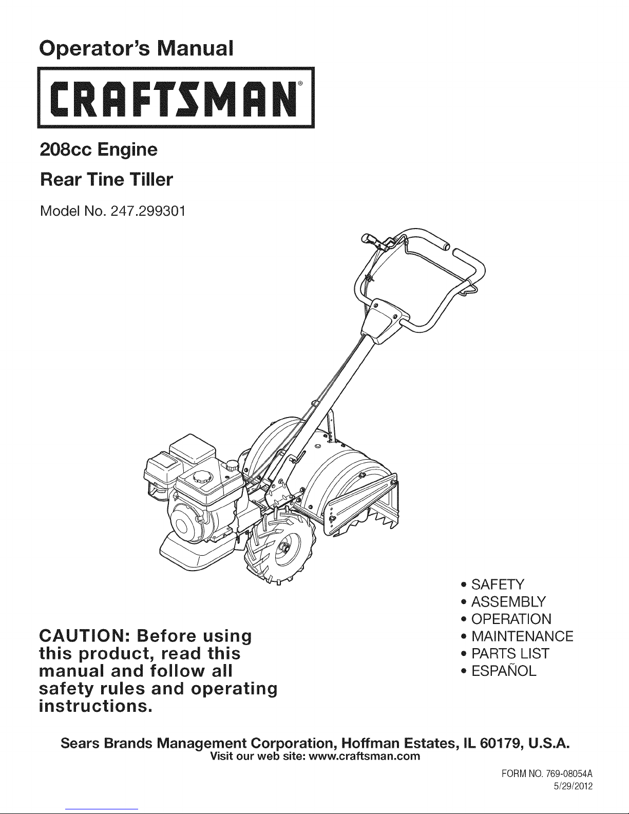
Operator's Manual
I:Rl FI'SlVl N
208cc Engine
Rear Tine Tiller
Model No. 247.299301
CAUTION: Before using
this product, read this
manual and follow aJl
safety rules and operating
instructions.
Sears Brands Management Corporation, Hoffman Estates, IL 60179, U.S.A.
Visit our web site: www.craftsman.com
* SAFETY
* ASSEMBLY
* OPERATION
* MAINTENANCE
* PARTS LIST
* ESPANOL
FORMNO.769-08054A
5/29/2012
Page 2
WarrantyStatement..................................Pac
Safetyinstructions....................................Pac
Assembly..................................................Pac
Operation..................................................Pac
ServiceandMaintenance.........................Pac
Off-SeasonStorage..................................Pac
TroubleShooting.......................................Pac
CRAFTSMAN TWO YEAR FULL WARRANTY
FORTWOYEARSfromthe dateof purchase,this productis warrantedagainstanydefectsin materialorworkmanship,A defectiveproductwill
receivefreerepairorreplacementif repairis unavailable,
Forwarranty coverage details to obtain free repairor replacement,visit the web site: www.craftsman.com
This warranty covers ONLYdefects in material andworkmanship. Warrantycoverage does NOTinclude:
• Expendableitemsthatcan wearoutfromnormalusewithinthewarrantyperiod,suchas theblades,tines,orbelts.
• Productdamageresultingfromuserattemptsat productmodificationor repairorcausedby productaccessories.
• Repairsnecessarybecauseof accidentorfailuretooperateor maintaintheproductaccordingtoall suppliedinstructions.
• Preventivemaintenance,or repairsnecessarydueto improperfuelmixture,contaminatedor stalefuel.
e2
es3-6
es7-10
es11-16
es17-22
e23
e24
PartsList...................................................Page26-40
Labels.......................................................Page41
RepairProtectionAgreement...................Page44
Espa_ol.....................................................Page45
ServiceNumbers......................................BackCover
Thiswarrantyisvoidif thisproductiseverusedwhile providingcommercialservicesorif rentedtoanotherperson.
Thiswarrantygivesyouspecificlegalrights,andyou mayalsohaveotherrightswhichvaryfromstatetostate.
Sears Brands Management Corporation, Hoffman Estates, IL 60179
EngineSeries: 208cc
EngineOilType: 10w30
EngineOilCapacity: 20ounces
Fuel: UnleadedGasoline
SparkPlug: F6RTC
SparkPlugGap: .030"
ModelNumber.................................................................
Serial Number .................................................................
Dateof Purchase.............................................................
Recordthemodelnumber,serialnumber
anddateof purchaseabove
©SearsBrands,LLC 2
Page 3
Thissymbolpointsout importantsafetyinstructionswhich,if not
followed,couldendangerthepersonalsafetyand/orpropertyof
yourselfandothers. Readandfollowall instructionsin thismanual
beforeattemptingtooperatethismachine.Failuretocomplywith
theseinstructionsmayresultin personalinjury.Whenyou seethis
symbol,HEEDITSWARNING!
Thismachinewasbuiltto beoperatedaccordingto thesafeopera-
tionpracticesinthismanual.Aswithanytypeof powerequipment,
carelessnessorerroronthe partof theoperatorcan resultin
seriousinjury.Thismachineiscapableofamputatingfingers,hands,
toesandfeetandthrowingdebris.Failureto observethefollowing
safetyinstructionscouldresultin seriousinjuryordeath.
CALIFORNIA PROPOSITION 65
EngineExhaust,someof itsconstituents,andcertainvehicle
componentscontainoremitchemicalsknowntoStateof California
tocausecancerandbirthdefectsorotherreproductiveharm.Bat-
tery posts,terminals,andrelatedaccessoriescontainleadand lead
compounds,chemicalsknowntothe Stateof Californiatocause
cancerandreproductiveharm.Washhandsafterhandling.
TRAINING
• Read,understand,andfollowall instructionson the machineand
in themanual(s)beforeattemptingtoassembleandoperate.
Keepthis manualina safeplaceforfutureand regularreference
andfororderingreplacementparts.
• ReadtheOperator'sManualand followallwarningsand safety
instructions.Failuretodosocan resultin seriousinjuryto the
operatorand/or bystanders.Forquestions,call1-800-4MY-HOME.
• Befamiliarwithall controlsandtheirproperoperation.Knowhow
tostopthe machineanddisengagethemquickly.
• Neverallowchildrenunder14yearsof agetooperatethis
machine.Children14andovershouldreadandunderstandthe
instructionsandsafeoperationpracticesin thismanualandon
themachineandbe trainedandsupervisedbyanadult.
• Neverallowadultstooperatethis machinewithoutproper
instruction.
• Keepbystanders,pets,andchildrenatleast75feetfromthe
machinewhileit isin operation.Stopmachineifanyoneenters
thearea.
• Neverrunanengineindoorsor ina poorlyventilatedarea.Engine
exhaustcontainscarbonmonoxide,anodorlessanddeadlygas.
Your Responsibility--Restrictthe useof thispowermachineto
personswhoread,understandandfollowthewarningsandinstruc-
tionsin thismanualandon the machine.
SAVETHESEINSTRUCTIONS!
PREPARATION
• Thoroughlyinspecttheareawheretheequipmentistobeused.
Removeall rocks,bottles,cans,or otherforeignobjectswhich
couldbepickedupor thrownandcausepersonalinjuryor
damageto themachine.
• Alwayswearsafetyglassesor safetygogglesduringoperation
andwhileperformingan adjustmentorrepair,to protectyour
eyes.Thrownobjectswhichricochetcancauseseriousinjuryto
theeyes.
• Wearsturdy,rough-soledworkshoesandclose-fittingslacksand
shirts.Loosefittingclothesorjewelrycan becaughtin movable
parts.Neveroperatethismachineinbarefeetorsandals.
• Beforestarting,checkallboltsandscrewsfor propertightnessto
besurethe machineisinsafeworkingcondition.Also,visually
inspectmachinefor anydamageatfrequentintervals.
• Disengageclutchleversandshift(if provided)into neutral("N")
beforestartingtheengine.
• Neverleavethismachineunattendedwiththeenginerunning.
• Neverattempttomakeanyadjustmentswhilethe engineis
running,exceptwherespecificallyrecommendedinthe operator's
manual.
• Maintainorreplacesafetyandinstructionslabels,asnecessary.
3
Page 4
SafeHandling of Gasoline:
Toavoidpersonalinjuryor propertydamageuseextremecarein
handlinggasoline.Gasolineisextremelyflammableandthe vaporsare
explosive.Seriouspersonalinjurycan occurwhengasolineisspilled
onyourselforyourclotheswhichcan ignite.Washyourskinand
changeclothesimmediately.
• Useonlyan approvedgasolinecontainer.
• Neverfill containersinsidea vehicleor ona truckor trailerbed
witha plasticliner.Alwaysplacecontainersonthe groundaway
fromyourvehiclebeforefilling.
• Whenpractical,removegas-poweredequipmentfromthetruck
ortrailerand refuelitonthe ground.Ifthisis notpossible,then
refuelsuchequipmentona trailerwitha portablecontainer,rather
thanfroma gasolinedispensernozzle.
• Keepthe nozzleincontactwiththerimofthe fueltankor
containeropeningatalltimes untilfuelingiscomplete.Donotuse
a nozzlelock-opendevice.
• Extinguishallcigarettes,cigars,pipesandother sourcesof
ignition.
• Neverfuel machineindoors.
• Neverremovegascapor addfuel whilethe engineishot or run-
ning.Allowenginetocool atleasttwo minutesbeforerefueling.
• Neveroverfillfueltank.Fill tankto nomorethan1/2inchbelow
bottomoffillerneckto allowspacefor fuelexpansion.
• Replacegasolinecapandtightensecurely.
• Ifgasolineisspilled,wipe itoff theengineandequipment.Move
unitto anotherarea.Wait5 minutesbeforestartingtheengine.
• To reducefirehazards,keepmachinefreeof grass,leaves,or
otherdebrisbuild-up.Cleanupoil orfuelspillageand removeany
fuelsoakeddebris.
• Neverstorethe machineorfuelcontainerinsidewherethereis an
openflame,sparkor pilotlightas on awaterheater,spaceheater,
furnace,clothesdryerorothergasappliances.
OPERATION
• Do notputhandsorfeetnear rotatingparts.Contactwiththe
rotatingpartscanamputatehandsandfeet.
• Do notoperatemachinewhileunderthe influenceofalcoholor
drugs.
• Neveroperatethismachinewithoutgoodvisibilityor light.Always
be sureof yourfootingandkeepa firmholdonthehandles.
• Keepbystandersawayfromthe machinewhileit isinoperation.
Stopthe machineif anyoneentersthearea.
• Becarefulwhentillinginhardground.Thetines maycatchinthe
groundandpropelthetillerforward.Ifthis occurs,let goofthe
handlebarsanddo not restrainthemachine.
• Exerciseextremecautionwhenoperatingonor crossinggravel
surfaces.Stayalertforhiddenhazardsortraffic. Donotcarry
passengers.
• Neveroperatethemachineat hightransportspeedsonhardor
slipperysurfaces.
• Exercisecautiontoavoidslippingorfalling.
• Lookdownand behindandusecarewhenin reverseor pulling
machinetowardsyou.
• Startthe engineaccordingtothe instructionsfoundinthis manual
and keepfeetwell awayfromthetinesat all times.
• Afterstrikingaforeignobjector ifyourmachineshouldstartmak-
inganunusualnoiseor vibration,immediatelyshutthe engineoff.
Disconnectthe sparkplugwire,grounditagainstthe engineand
performthefollowingsteps:
a. Inspectfordamage.
b. Repairorreplaceanydamagedparts.
c. Checkforanyloosepartsandtightento assurecontinued
safeoperation.
• Disengageall clutchlevers(iffitted)and stopenginebeforeyou
leavethe operatingposition(behindthe handles).Waituntil
thetinescometo a completestopbeforeuncloggingthe tines,
makinganyadjustments,or inspections.
• Neverrunanengineindoorsorina poorlyventilatedarea.Engine
exhaustcontainscarbonmonoxide,an odorlessanddeadlygas.
• Mufflerandenginebecomehotandcancausea burn.Do not
touch.
• Usecautionwhentillingnearfences,buildingsandunderground
utilities.Rotatingtinescan causepropertydamageorpersonal
injury.
• Donotoverloadmachinecapacitybyattemptingtotillsoil too
deepattoo fastof a rate.
• Ifthe machineshouldstartmakinganunusualnoiseor vibration,
stoptheengine,disconnectthesparkplugwire andgroundit
againsttheengine.Inspectthoroughlyfordamage.Repairany
damagebeforestartingandoperating.
• Keepallshields,guards,and safetydevicesinplaceandoperat-
ing properly.
• Neverpickuporcarrymachinewhiletheengineis running.
• Useonly attachmentsandaccessoriesapprovedbythe manu-
factureras listedin thePartsListpagesofthisoperator'smanual.
Failuretodosocan resultin personalinjury.
• Ifsituationsoccurwhichare notcoveredinthis manual,usecare
andgoodjudgement.ContactCustomerSupportat 1-800-4MY-
HOMEforassistanceandthenameof thenearestservicedealer
MAINTENANCE & STORAGE
• Keepthemachine,attachmentsandaccessoriesin safeworking
order.
• Allowthemachinetocoolat leastfiveminutesbeforestoring.
Nevertamperwithsafetydevices.Checktheirproperoperation
regularly.
• Checkboltsandscrewsforpropertightnessat frequentintervals
to keepthemachineinsafeworkingcondition.Also,visually
inspectmachineforanydamage.
• Beforecleaning,repairing,or inspecting,stopthe engineand
makecertainthetinesandall movingpartshavestopped.
Disconnectthe sparkplugwireandgrounditagainsttheengineto
preventunintendedstarting.
4
Page 5

• Do notchangetheenginegovernorsettingsor over-speedthe
engine.Thegovernorcontrolsthemaximumsafeoperatingspeed
ofengine.
Maintainor replacesafetyandinstructionlabels,as necessary.
Followthis manualfor safeloading,unloading,transporting,and
storageof thismachine.
Alwaysreferto theoperator'smanualforimportantdetailsifthe
machineisto bestoredforan extendedperiod.
If thefuel tankhasto be drained,do thisoutdoors.
Observeproperdisposallawsandregulationsforgas,oil, etc.to
protecttheenvironment.
Accordingtothe ConsumerProductsSafetyCommission(CPSC)
andtheU.S.EnvironmentalProtectionAgency(EPA),thisproduct
hasan AverageUsefulLifeof seven(7)years,or 130hoursof
operation.Atthe endof theAverageUsefulLifehavethemachine
inspectedannuallybyanauthorizedservicedealertoensurethat
allmechanicalandsafetysystemsareworkingproperlyandnot
wornexcessively.Failureto do socan resultinaccidents,injuries
ordeath.
DO NOT MODIFY ENGINE
Toavoidseriousinjuryordeath,donot modifyenginein anyway.
Tamperingwiththegovernorsettingcan leadto a runawayengineand
causeitto operateat unsafespeeds.Nevertamperwithfactorysetting
ofenginegovernor.
NOTICE REGARDING EMISSIONS
EngineswhicharecertifiedtocomplywithCaliforniaandfederal
EPAemissionregulationsfor SORE(SmallOff RoadEquipment)are
certifiedto operateonregularunleadedgasoline,and mayinclude
thefollowingemissioncontrolsystems:EngineModification(EM),
OxidizingCatalyst(CO),SecondaryAirInjection(SAI)and ThreeWay
Catalyst(TWO)if soequipped.
SPARK ARRESTOR
Thismachineis equippedwithan internalcombustionengineand
shouldnotbe usedonor nearanyunimprovedforest-covered,
brushcoveredor grass-coveredlandunlesstheengine'sexhaust
systemisequippedwitha sparkarrestormeetingapplicablelocalor
statelaws(if any)
Ifa sparkarrestorisused,it shouldbe maintainedin effectiveworking
orderbytheoperator.Inthe StateofCaliforniatheaboveis required
bylaw (Section4442ofthe CaliforniaPublicResourcesCode).Other
statesmayhavesimilarlaws. Federallawsapplyonfederallands.
A sparkarrestorforthe muffleris availablethroughyournearestSears
PartsandRepairServiceCenter.
Page 6

SAFETY SYMBOLS
Thispagedepictsanddescribessafetysymbolsthatmayappearonthisproduct. Read,understand,andfollowallinstructionson themachine
beforeattemptingto assembleandoperate.
READ THE OPERATOR'S MANUAL(S)
i
i
Read, understand, and follow all instructions in the manual(s) before attempting to assemble and
operate
WARNING-- ROTATING TINES
Do not put hands or feet near rotating parts. Contact with the rotating parts can amputate
hands and feet.
WARNING-- ROTATING TINES
Do not put hands or feet near rotating parts. Contact with the rotating parts can amputate
hands and feet.
WARNING--GASOLINE IS FLAMMABLE
Allow the engine to cool at least two minutes before refueling.
WARNING-- CARBON MONOXIDE
Never run an engine indoors or in a poorly ventilated area. Engine exhaust contains carbon
monoxide, an odorless and deadly gas.
WARNING-- HOT SURFACE
Engine parts, especially the muffler, become extremely hot during operation. Allow engine
and muffler to cool before touching.
WARNING: YourResponsibility--Restricttheuseofthispowermachineto personswhoread,understandandfollowthe
warningsand instructionsinthis manualandonthemachine.
SAVETHESEINSTRUCTIONS!
6
Page 7
NOTE:Thisunitis shippedwithoutgasolineor oil intheengine.Be
certaintoserviceenginewithgasolineandoil as instructedin the
Operationsectionofthis manualbeforeoperatingyourmachine.
NOTE:Referenceto rightand lefthandsideof theTillerisobserved
fromtheoperatingposition.
OPENING CARTON
1. Removeallstaplesfromaroundthebottomofthe perimeter.
2. Removethecartonfromtheskid.
3. Removealllooseparts.
4. Removeloosepackingmaterial.
REMOVING UNIT FROM SKID
1. Thetiller isheavy,do notattemptto removeitfromtheskiduntil
instructedtodo so intheseassemblysteps.
2. Checkcartonthoroughlyforanyotherlooseparts.
LOOSE PARTS IN CARTON
• HandlebarAssembly
• Tiller
• EngineOil
• Operator'sManual
ATTACHING THE HANDLE ASSEMBLY
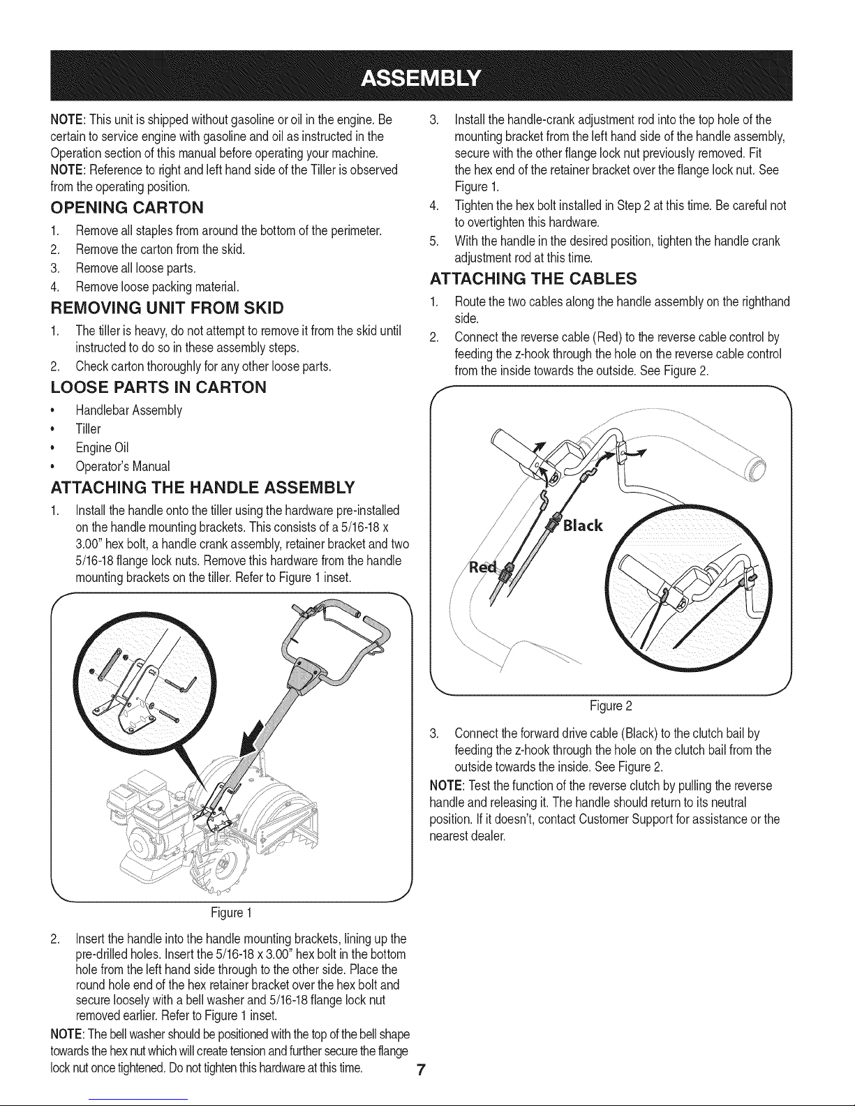
1. Installthe handleontothetillerusingthehardwarepre-installed
onthehandlemountingbrackets.Thisconsistsofa 5/16-18x
3.00"hexbolt,a handlecrankassembly,retainerbracketandtwo
5/16-18flangelocknuts.Removethishardwarefromthehandle
mountingbracketson thetiller.Referto Figure1inset.
f -_,
3. Installthehandle-crankadjustmentrod intothe topholeof the
mountingbracketfromtheleft handsideof thehandleassembly,
securewiththeotherflangelocknut previouslyremoved.Fit
thehexend ofthe retainerbracketoverthe flangelocknut.See
Figure1.
4. Tightenthehexboltinstalledin Step2 atthis time.Becarefulnot
toovertightenthishardware.
5. Withthehandlein the desiredposition,tightenthehandlecrank
adjustmentrodatthistime.
ATTACHING THE CABLES
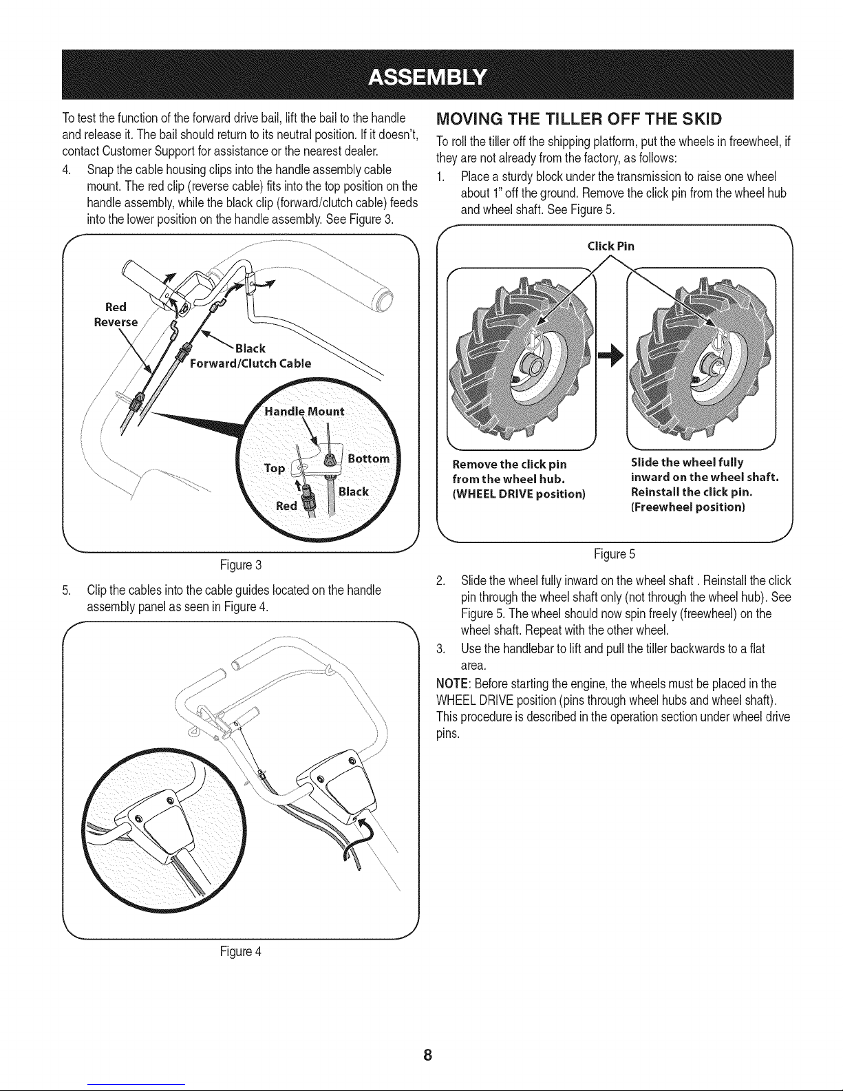
1. Routethetwocablesalongthe handleassemblyon therighthand
side.
2. Connectthe reversecable(Red)tothe reversecablecontrolby
feedingthez-hookthroughthe holeon thereversecablecontrol
fromtheinsidetowardstheoutside.SeeFigure2.
f ---
/
Figure1
2. Insertthe handleintothe handlemountingbrackets,liningupthe
pre-drilledholes.Insertthe5/16-18x3.00"hexboltinthebottom
holefromtheleft handside throughtotheotherside.Placethe
roundholeendofthe hexretainerbracketoverthehexboltand
securelooselywitha bellwasherand5/16-18flangelocknut
removedearlier.Referto Figure1inset.
NOTE:Thebellwashershouldbepositionedwiththetopd thebellshape
towardsthehexnutwhichwillcreatetensionandfurthersecuretheflange
locknutoncetightened.Donottightenthishardwareatthistime. 7
Figure2
3. Connecttheforwarddrivecable(Black)tothe clutchbailby
feedingthez-hookthroughthe holeon theclutchbailfromthe
outsidetowardstheinside.SeeFigure2.
NOTE:Testthefunctionofthe reverseclutchby pullingthe reverse
handleand releasingit.The handleshouldreturntoits neutral
position.If it doesn't,contactCustomerSupportforassistanceorthe
nearestdealer.
Page 8
Totest thefunctionoftheforwarddrivebail,lift thebailto thehandle
andreleaseit.The bailshouldreturntoits neutralposition.Ifit doesn't,
contactCustomerSupportforassistanceorthe nearestdealer.
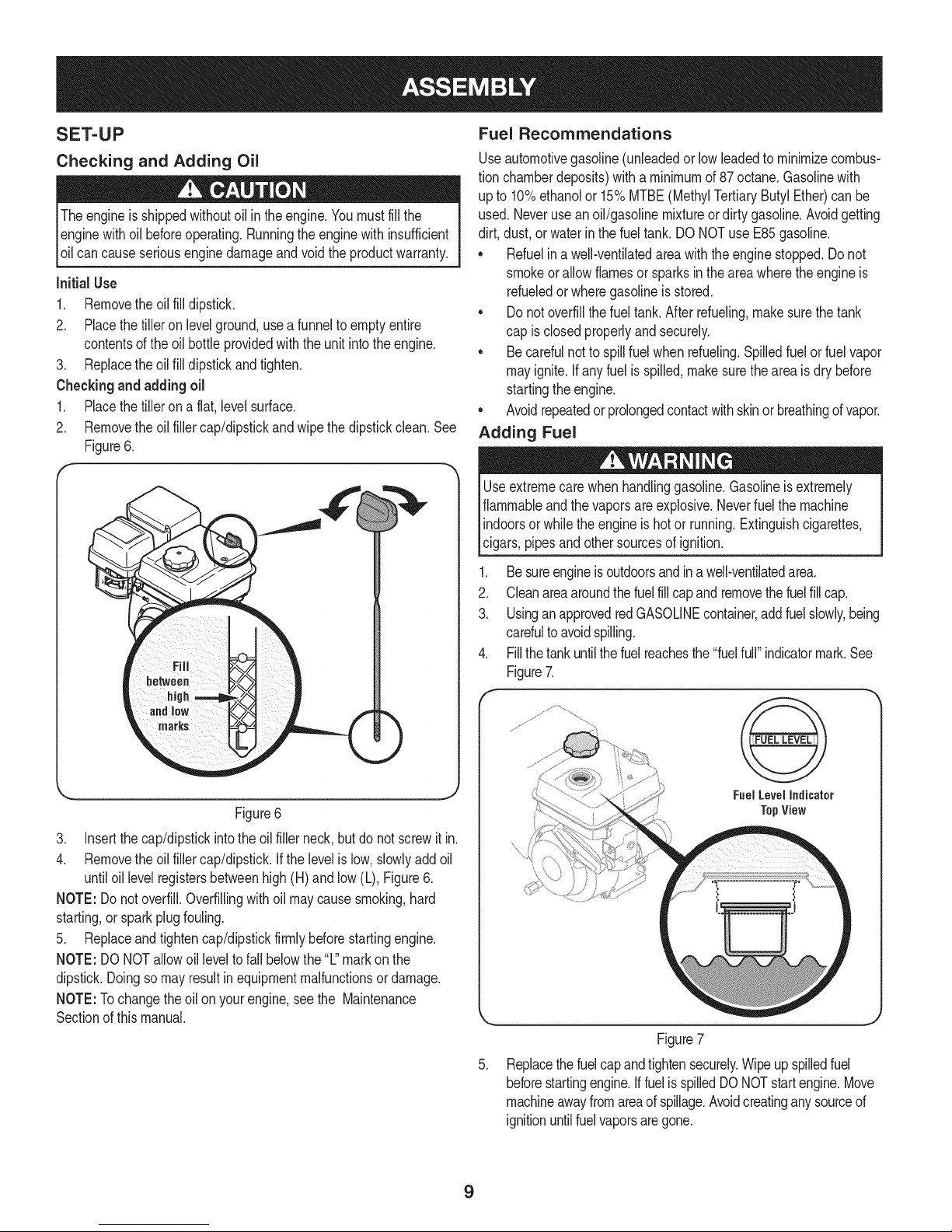
4. Snapthecablehousingclipsintothehandleassemblycable
mount.Theredclip(reversecable)fitsinto thetop positiononthe
handleassembly,whiletheblackclip (forward/clutchcable)feeds
intothe lowerpositiononthe handleassembly.See Figure3.
Red
Reverse
MOVING THE TILLER OFF THE SKID
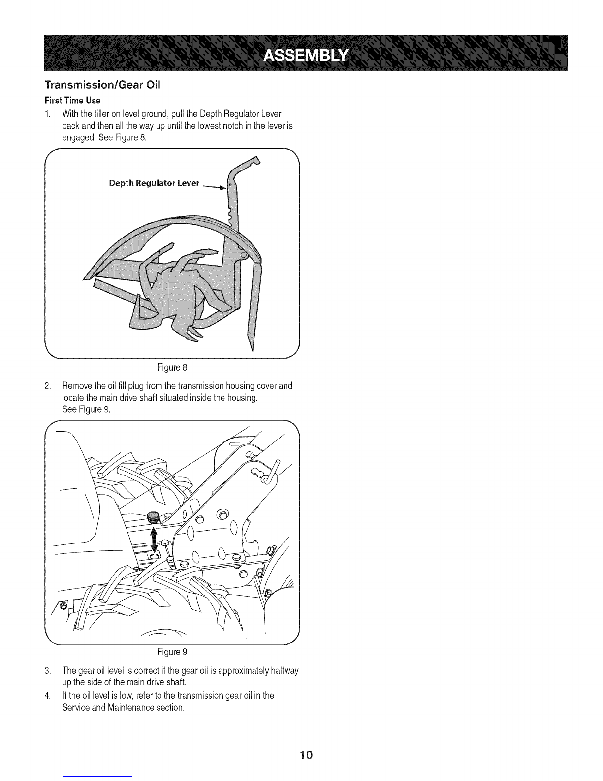
Torollthetilleroff the shippingplatform,put thewheelsinfreewheel,if
theyarenotalreadyfromthefactory,asfollows:
1. Placeasturdyblockunderthetransmissiontoraiseonewheel
about1"off theground.Removetheclickpinfromthewheelhub
andwheelshaft.SeeFigure5.
f
Click Pin
Figure3
Clipthe cablesintothe cableguideslocatedon thehandle
assemblypanelas seenin Figure4.
Remove the click pin
from the wheel hub.
(WHEEL DRIVE position)
Slide the wheel fully
inward on the wheel shaft.
Reinstall the click pin.
(Freewheel position)
Figure5
2. Slidethewheelfullyinwardonthe wheelshaft. Reinstalltheclick
pinthroughthewheelshaftonly(notthroughthewheelhub).See
Figure5.Thewheel shouldnowspinfreely(freewheel)onthe
wheelshaft.Repeatwiththeotherwheel.
3. Usethehandlebartolift andpullthetillerbackwardstoa flat
area.
NOTE:Beforestartingtheengine,thewheelsmustbe placedinthe
WHEELDRIVEposition(pinsthroughwheelhubsandwheel shaft).
Thisprocedureisdescribedintheoperationsectionunderwheeldrive
pins.
Figure4
J
8
Page 9
SET-UP
Checking and Adding Oil
Theengineis shippedwithoutoil intheengine.Youmustfill the
enginewithoil beforeoperating.Runningtheenginewithinsufficient
_o cancauseserous engnedamageandvod the productwarranty.
Initial Use
1. Removetheoil filldipstick.
2. Placethetilleron levelground,usea funnelto emptyentire
contentsofthe oil bottleprovidedwiththe unitintotheengine.
3. Replacetheoil fill dipstickandtighten.
Checkingand adding oil
1. Placethetillerona flat, levelsurface.
2. Removetheoil fillercap/dipstickandwipethedipstickclean.See
Figure6.
Fuel Recommendations
Useautomotivegasoline(unleadedorlowleadedtominimizecombus-
tionchamberdeposits)witha minimumof 87 octane.Gasolinewith
up to 10%ethanolor 15%MTBE(MethylTertiaryButylEther)canbe
used.Neverusean oil/gasolinemixtureordirty gasoline.Avoidgetting
dirt, dust,or waterinthe fueltank.DONOTuse E85gasoline.
• Refuelina well-ventilatedareawiththe enginestopped.Donot
smokeorallowflamesor sparksin theareawheretheengineis
refueledor wheregasolineisstored.
• Donotoverfillthe fueltank.After refueling,makesurethe tank
capis closedproperlyandsecurely.
• Becarefulnotto spillfuelwhenrefueling.Spilledfuelorfuel vapor
mayignite.Ifany fuelis spilled,makesurethe areaisdry before
startingthe engine.
• Avoidrepeatedor prolongedcontactwithskinorbreathingofvapor.
Adding Fuel
Useextremecarewhenhandlinggasoline.Gasolineisextremely
flammableandthevaporsareexplosive.Neverfuelthe machine
indoorsorwhilethe engineishotor running.Extinguishcigarettes,
cigars,pipesandothersourcesof ignition.
1. Besureengineisoutdoorsandina well-ventilatedarea.
2. Cleanareaaroundthefuelfill capandremovethefuelfill cap.
3. UsinganapprovedredGASOLINEcontainer,addfuelslowly,being
carefultoavoidspilling.
4. Fillthetankuntilthefuelreachesthe "fuelfull"indicatormark.See
Figure7.
Figure6
3. Insertthe cap/dipstickintothe oilfillerneck,butdo not screwitin.
4. Removetheoil fillercap/dipstick.Ifthelevelislow,slowlyaddoil
untiloil levelregistersbetweenhigh(H) and low(L), Figure6.
NOTE:Donotoverfill.Overfillingwithoil maycausesmoking,hard
starting,or sparkplugfouling.
5. Replaceandtightencap/dipstickfirmlybeforestartingengine.
NOTE:DONOTallowoil leveltofall belowthe"L"markon the
dipstick.Doingsomayresultinequipmentmalfunctionsordamage.
NOTE:Tochangethe oilon yourengine,seethe Maintenance
Sectionofthismanual.
Fuel Level Indicator
TopView
Figure7
.
Replacethefuelcapandtightensecurely.Wipeupspilledfuel
beforestartingengine.IffuelisspilledDONOTstartengine.Move
machineawayfromareaofspillage.Avoidcreatinganysourceof
ignitionuntilfuelvaporsaregone.
9
Page 10
Transmission/Gear Oil
First Time Use
1. Withthetilleron levelground,pullthe DepthRegulatorLever
backandthenallthe wayup untilthe lowestnotchinthe leveris
engaged.SeeFigure8.
F
Depth Regulator Lever
Figure8
,
Removetheoil fillplugfromthetransmissionhousingcoverand
locatethemaindriveshaft situatedinsidethe housing.
SeeFigure9.
\
\
Figure9
3. Thegearoil leveliscorrectifthe gearoilisapproximatelyhalfway
uptheside ofthe maindriveshaft.
4. If theoillevelislow,refertothetransmissiongearoilinthe
ServiceandMaintenancesection.
10
Page 11
f
Forward Clutch Bail
Fuel Cap & Tine Engagement
Muffler
Air Filter
Choke
Throttle
Pull Starter Handle
OUFill Cap
& Dipstick
Oil Drain
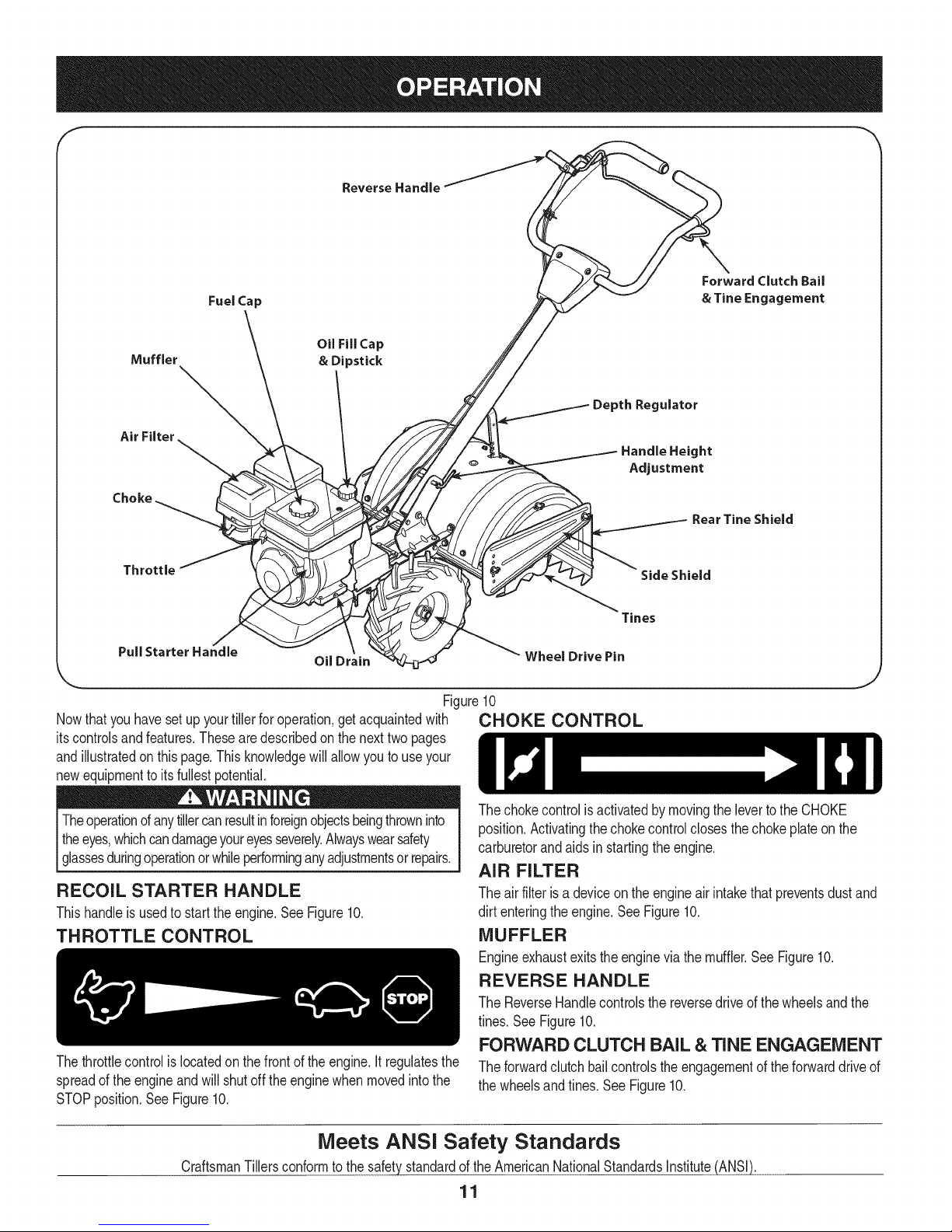
Nowthat youhavesetup yourtillerforoperation,getacquaintedwith
itscontrolsandfeatures.Thesearedescribedon thenexttwopages
andillustratedonthispage.Thisknowledgewillallowyouto useyour
newequipmenttoitsfullestpotential.
ulator
Handle Height
Adjustment
Rear Tine Shield
Side Shield
Tines
Wheel Drive Pin
,J
Figure10
CHOKE CONTROL
Theoperationofanytillercanresultinforeignobjectsbeingthrowninto
theeyes,whichcandamageyoureyesseverely.Alwayswearsafety
[gassesdurngoperatonorwh eperformnganyadjustmentsorrepars.
RECOIL STARTER HANDLE
Thishandleisusedto starttheengine.See Figure10.
THROTTLE CONTROL
Thethrottlecontrolislocatedonthefrontof theengine.It regulatesthe
spreadoftheengineandwill shutoff theenginewhen movedintothe
STOPposition.SeeFigure10.
Meets ANSi Safety Standards
CraftsmanTillersconformtothe safetystandardofthe AmericanNationalStandardsInstitute(ANSI).
Thechokecontrolisactivatedbymovingtheleverto theCHOKE
position.Activatingthe chokecontrolclosesthechokeplateonthe
carburetorandaidsinstartingtheengine.
AIR FILTER
Theairfilteris a deviceon theengineairintakethatpreventsdustand
dirtenteringtheengine.SeeFigure10.
MUFFLER
Engineexhaustexitstheenginevia themuffler.SeeFigure10.
REVERSE HANDLE
TheReverseHandlecontrolsthe reversedriveofthe wheelsandthe
tines.SeeFigure10.
FORWARD CLUTCH BAiL & TINE ENGAGEMENT
Theforwardclutchbailcontrolstheengagementofthe forwarddriveof
thewheelsandtines.See Figure10.
11
Page 12
OiL FiLL CAP & DIPSTICK
Engineoil levelcanbecheckedandoiladdedthroughtheoil fill. See
Figure10.
NOTE:Thisunitwasshipped%THOUToil inthe engine.Oilis
includedintheplasticbag packedwiththemanualinwiththeunit.Add
theoilas directedintheAssemblysection.Checktheoil levelbefore
eachoperationtoensureadequateoilisintheengine.Forfurther
instructions,referto thestepsinthe ServiceandMaintenancesection
ofthismanual.
DEPTH REGULATOR LEVER
Thislevercontrolsthetillingdepthof thetines.Pulltheleverbackand
slideit upor downto engagethenotchedheight.SeeFigure10.
HANDLEBAR HEIGHT ADJUSTMENT
Thehandlebarheightisadjustableto threedifferentsettings.In
general,adjustthehandlebarsso theyareatwaistlevelwhenthetines
are3-4"intheground.SeeFigure10.
REAR TIME SHIELD
Thereartine shieldprotectstheoperatorfromflyingdebriswhilealso
smoothingout freshlytilledsoil.SeeFigure10.
SiDE SHIELD
Theside shieldisusedto maintainclearevenrowsandmaybe
adjustedtooneof fivedifferentpositions.SeeFigure10.
TINES
Yourtiller'stinesarea seriesof hoesarrangedona revolvingpower-
drivenshaft.See Figure10.
WHEEL DRIVE PiNS
Eachwheelisequippedwitha wheeldriveclick pinthatsecuresthe
wheelto thewheel shaft.Thewheelscanbe positionedineithera
WHEELDRIVEor a FREEWHEELmode.SeeFigure10.
OiL DRAIN
Removingthe oildrainplugwilldrainthe oil fromtheengine.See
Figure10.
TO START ENGINE
1. Attachsparkplugwireand rubberboottosparkplug.
2. Filltankto nomorethan1/2inchbelowbottomof fillerneckto
providespaceforfuelexpansion.
3. Putthe wheelsintheWHEELDRIVEposition.
4. MovetheDepthRegulatorLeverallthewaydownto the"trans-
port"position,sothatthetinescleartheground.
5. Releaseall ofthecontrolsonthe tiller.
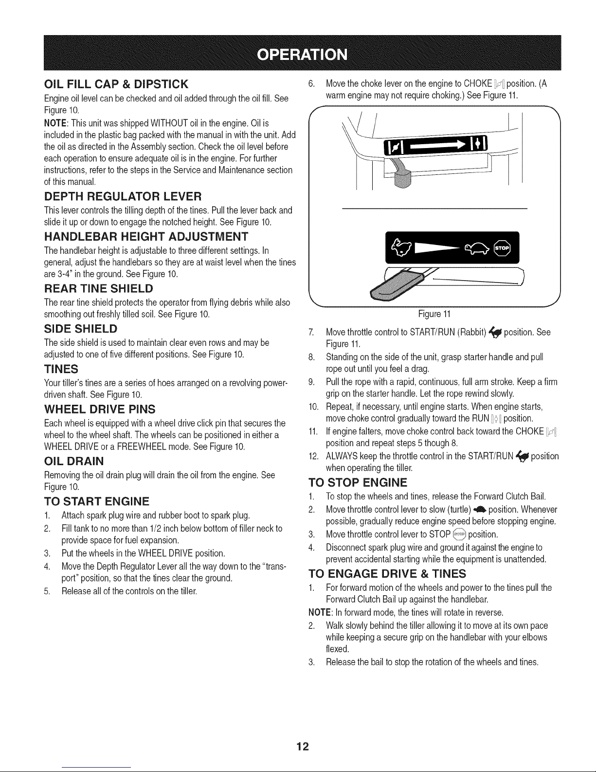
6. Movethechokeleveron theengineto CHOKE_÷ position.(A
warmenginemaynotrequirechoking.)SeeFigure11.
f -,
_.. .J
Figure11
7. Movethrottlecontrolto START/RUN(Rabbit)_ position.See
Figure11.
8. Standingon the sideof theunit,graspstarterhandleandpull
ropeoutuntilyoufeela drag.
9. Pullthe ropewitha rapid,continuous,fullarm stroke.Keepafirm
gripon thestarterhandle.Letthe roperewindslowly.
10. Repeat,ifnecessary,untilenginestarts.Whenenginestarts,
movechokecontrolgraduallytowardthe RUN_[ position.
11. Ifenginefalters,movechokecontrolbacktowardtheCHOKEi:_
positionand repeatsteps5 though8.
12. ALWAYSkeepthethrottlecontrolintheSTART/RUN,_ position
whenoperatingthetiller.
TO STOP ENGINE
1. To stopthewheelsandtines, releasetheForwardClutchBail.
2. Movethrottlecontrolleverto slow(turtle)_ position.Whenever
possible,graduallyreduceenginespeedbeforestoppingengine.
3. Movethrottlecontrolleverto STOP_ position.
4. Disconnectsparkplugwireandgrounditagainsttheengineto
preventaccidentalstartingwhilethe equipmentisunattended.
TO ENGAGE DRIVE & TINES
1. Forforwardmotionofthewheelsandpowertothe tinespullthe
ForwardClutchBailupagainstthe handlebar.
NOTE:Inforwardmode,thetineswill rotatein reverse.
2. Walkslowlybehindthetillerallowingitto moveat itsown pace
whilekeepinga securegrip onthehandlebarwithyourelbows
flexed.
3. Releasethebailto stoptherotationofthewheelsandtines.
12
Page 13
To move tiller in reverse: (Do not till in reverse)
a. ReleasetheForwardClutchBail.
b. Liftthe handlebaruntilthetinesare offthe ground.
c. Slowlypull backonthe ReverseLever,andcarefullywalk
backwardswiththe machine.
NOTE:In reversemode,thetineswill rotateforward.
d. If longerdistancesneedtobe coveredinreverse,shutoff the
engine,thenplacethe twowheelsinFREEWHEEL.
TURNING THE TILLER
1. Practiceturningthetillerin a level,openarea.Beverycarefulto
keepyourfeetandlegsawayfromthe tines.
2. Tobeginaturn,liftthe handlebarsuntilthetinesareout ofthe
groundandtheengineandtinesarebalancedoverthewheels.
3. Withthetillerbalanced,pushsidewayson the handlebartosteer
inthedirectionoftheturn.Afterturning,slowlylowerthe tinesinto
thesoil toresumetilling.
SETTING THE DEPTH
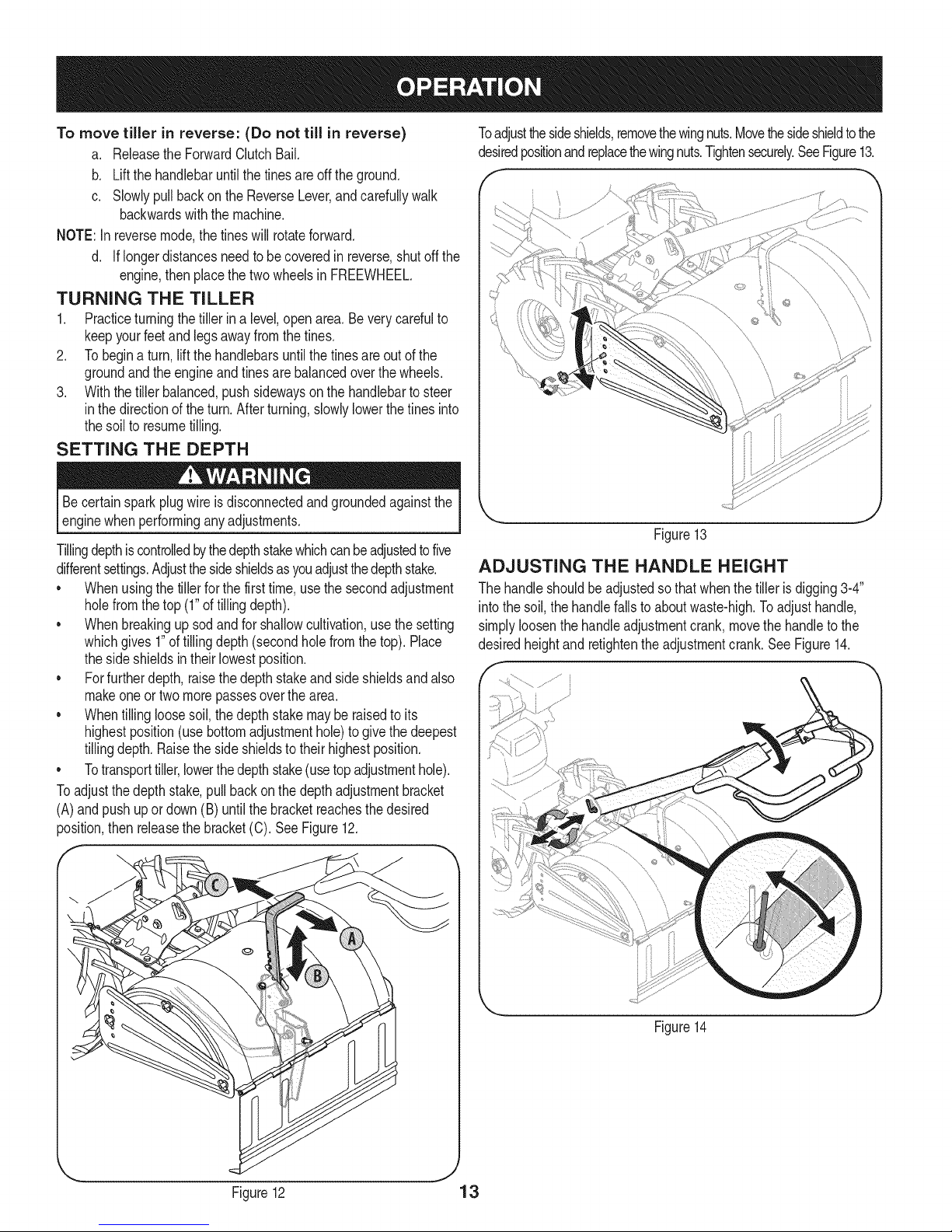
Toadjustthesideshields,removethewingnuts.Movethesideshieldto the
desiredpositionandreplacethewingnuts.Tightensecurely.SeeFigure13.
f ---
\
Becertainsparkplugwireisdisconnectedandgroundedagainstthe
enginewhenperforminganyadjustments.
Tillingdepthiscontrolledbythedepthstakewhichcanbeadjustedtofive
differentsettings.Adjustthesideshieldsasyouadjustthedepthstake.
• Whenusingthe tillerfor thefirsttime,usethesecondadjustment
holefromthetop (1"oftillingdepth).
• Whenbreakingupsodandforshallowcultivation,usethe setting
whichgives1"oftillingdepth(secondholefromthetop).Place
thesideshieldsintheirlowestposition.
• Forfurtherdepth,raisethedepthstakeandsideshieldsandalso
makeoneor twomorepassesoverthearea.
• Whentillingloosesoil,thedepthstakemayberaisedtoits
highestposition(usebottomadjustmenthole)to givethedeepest
tillingdepth.Raisethe sideshieldsto theirhighestposition.
• Totransporttiller,lowerthedepthstake(usetopadjustmenthole).
Toadjustthedepthstake,pull backon thedepthadjustmentbracket
(A)and pushupor down(B) untilthe bracketreachesthe desired
position,thenreleasethebracket(C).SeeFigure12.
\ j
Figure13
ADJUSTING THE HANDLE HEIGHT
Thehandleshouldbeadjustedsothat whenthetiller isdigging3-4"
intothesoil,thehandlefallsto aboutwaste-high.Toadjusthandle,
simplyloosenthehandleadjustmentcrank,movethehandleto the
desiredheightand retightentheadjustmentcrank.See Figure14.
Figure12 13
Figure14
J
Page 14
CLEARING THE TINES
Beforeclearingthetinesby hand,stoptheengine,allowall moving
partstostopanddisconnectthesparkplugwire.Failuretofollowthis
warningcouldresultinpersonalinjury.
* Thetineshavea self-clearingactionwhicheliminatesmostof the
tanglingofdebris.However,occasionallydrygrass,stringystalks
ortoughvinesmaybecometangled.Followtheseproceduresto
helpavoidtanglingandtoclearthetines, ifnecessary.
* Toreducetangling,setthedepth regulatordeepenoughto get
maximum"chopping"actionasthe tineschopthe materialagainst
theground.Also,trytotill undercropresiduesorcovercrops
whiletheyaregreen,moistandtender.
* Whiletilling,tryswayingthehandlebarsfromsideto side(about
6"to 12").This"fishtailing"actionoftenclearsthetinesof debris.
TILLING TiPS & TECHNIQUES
Beforetilling,contactyourtelephoneor utilitiescompanyandinquire
l ifundergroundequipmentorlinesareusedon yourproperty.Donot
[till nearburiedelectriccables,telephonelines,pipesor hoses.
Tilling Depth
* ThisisaCRT(counter-rotatingtine)tiller.Asthewheelspull
forward,thetinesrotatebackward.Thiscreatesan"uppercut"
tineactionwhichdigsdeeply,uprootingsoilandweeds.Don't
overloadtheengine,but digasdeeplyas possibleoneachpass
On laterpasses,thewheelsmaytendto spininthe softdirt. Help
themalongbyliftingupslightlyonthe handlebar(onehand,palm
up,worksmosteasily).
* Avoidthetemptationto pushdownonthe handlebarsinan
attempttoforcethetillerto digdeeper.Doingsotakestheweight
off thepoweredwheels,causingthemto losetraction.Withoutthe
wheelstoholdthe tillerback,thetineswill attempttopropelthe
tillerbackward,towardstheoperator.
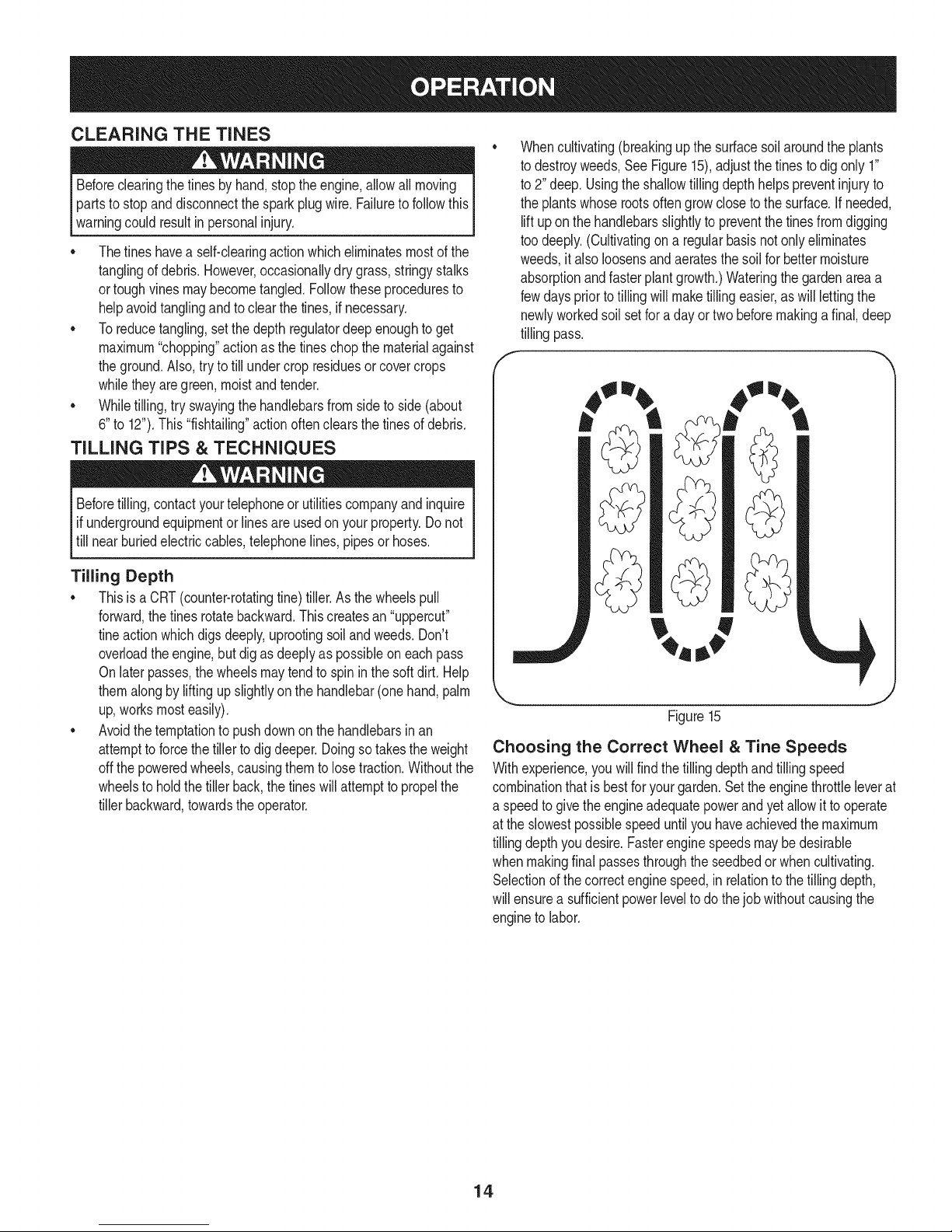
Whencultivating(breakingupthe surfacesoilaroundthe plants
todestroyweeds,SeeFigure15),adjustthe tinestodigonly 1"
to2" deep.Usingtheshallowtillingdepthhelpspreventinjuryto
theplantswhoserootsoftengrowclosetothe surface.Ifneeded,
liftupon thehandlebarsslightlyto preventthetinesfromdigging
toodeeply.(Cultivatingon a regularbasisnot onlyeliminates
weeds,it alsoloosensandaeratesthe soilfor bettermoisture
absorptionandfasterplantgrowth.)Wateringthegardenareaa
fewdayspriortotilling willmaketillingeasier,aswill lettingthe
newlyworkedsoilsetfor a dayor twobeforemakingafinal,deep
tillingpass.
Figure15
Choosing the Correct Wheel & Tine Speeds
Withexperience,you willfind thetilling depthandtillingspeed
combinationthatis bestforyourgarden.Settheenginethrottleleverat
a speedto givethe engineadequatepowerandyet allowit tooperate
atthe slowestpossiblespeeduntilyouhaveachievedthemaximum
tillingdepthyoudesire.Fasterenginespeedsmaybe desirable
whenmakingfinal passesthroughtheseedbedor whencultivating.
Selectionofthe correctenginespeed,inrelationtothetillingdepth,
willensurea sufficientpowerlevelto do thejobwithoutcausingthe
engineto labor.
14
Page 15
Suggested Tilling Patterns
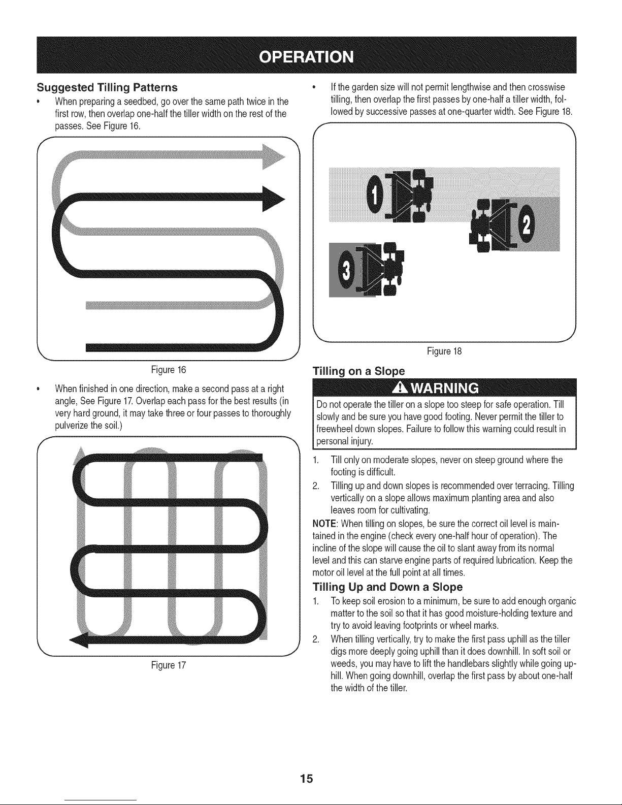
• Whenpreparinga seedbed,gooverthe samepathtwice inthe
firstrow,thenoverlapone-halfthetiller widthontherestof the
passes.SeeFigure16.
Ifthegardensizewill notpermitlengthwiseandthencrosswise
tilling,thenoverlapthefirst passesbyone-halfatiller width,fol-
lowedby successivepassesatone-quarterwidth.SeeFigure18.
f
Figure18
Figure16
Whenfinishedinonedirection,makea secondpassata right
angle,SeeFigure17.Overlapeachpassfor thebestresults(in
veryhardground,it maytakethreeorfour passestothoroughly
pulverizethesoil.)
f
m m m m
r
t_ m _ m
Figure17
Tilling on a Slope
Donotoperatethetillerona slopetoosteepfor safeoperation.Till
slowlyandbesureyouhavegoodfooting.Neverpermitthetillerto
freewheeldownslopes.Failuretofollowthiswarningcouldresultin
personalinjury.
1. Till onlyon moderateslopes,neveronsteepgroundwherethe
footingisdifficult.
2. Tillingupand downslopesis recommendedoverterracing.Tilling
verticallyon aslopeallowsmaximumplantingareaandalso
leavesroomforcultivating.
NOTE:Whentillingon slopes,be surethe correctoillevelismain-
tainedin theengine(checkeveryone-halfhourofoperation).The
inclineof theslopewillcausethe oilto slantawayfromits normal
levelandthis canstarveenginepartsof requiredlubrication.Keepthe
motoroil levelat thefull pointat all times.
Tilling Up and Down a Slope
1. To keepsoilerosionto a minimum,besureto addenoughorganic
matterto thesoil sothat it hasgoodmoisture-holdingtextureand
try toavoidleavingfootprintsor wheelmarks.
2. Whentillingvertically,tryto makethefirst passuphillasthetiller
J
digsmoredeeplygoinguphillthanit doesdownhill.Insoft soilor
weeds,youmayhaveto liftthehandlebarsslightlywhilegoingup-
hill.Whengoingdownhill,overlapthefirstpassby aboutone-half
thewidthof thetiller.
15
Page 16
Terrace Gardening
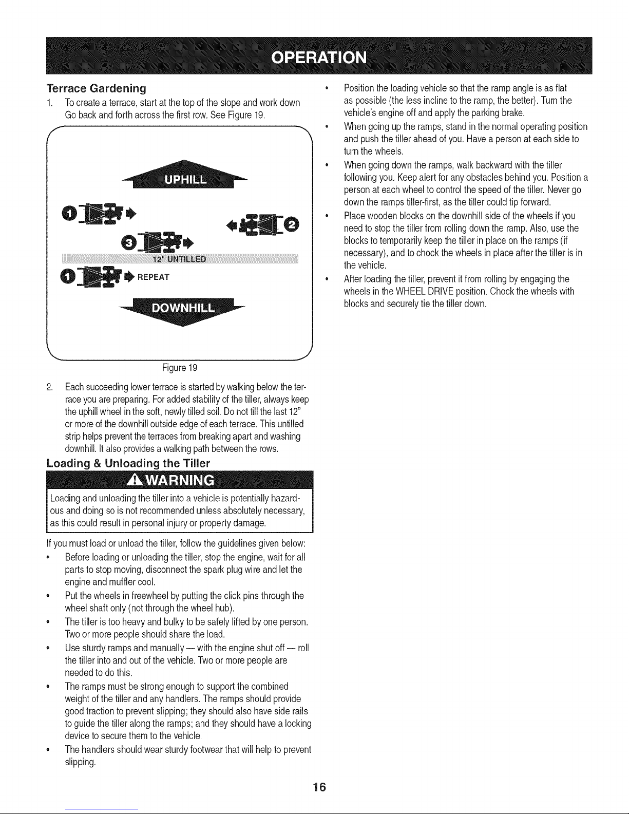
1. Tocreatea terrace,startatthetopof theslopeandworkdown
Gobackandforthacrossthefirstrow.See Figure19.
f
Figure19
• Positiontheloadingvehiclesothatthe rampangleis asflat
as possible(thelessinclineto theramp,the better).Turnthe
vehicle'sengineoffandapplytheparkingbrake.
• Whengoinguptheramps,standin thenormaloperatingposition
and pushthetilleraheadof you.Havea personateachsideto
turnthe wheels.
• Whengoingdownthe ramps,walkbackwardwiththetiller
followingyou.Keepalertfor anyobstaclesbehindyou.Positiona
personateachwheeltocontrolthe speedof thetiller.Nevergo
downthe rampstiller-first,asthetillercouldtip forward.
• Placewoodenblockson thedownhillsideof thewheelsif you
needtostopthe tillerfromrollingdowntheramp.Also,usethe
blockstotemporarilykeepthetiller in placeonthe ramps(if
necessary),andto chockthe wheelsin placeafterthe tilleris in
thevehicle.
• Afterloadingthe tiller,preventitfromrollingby engagingthe
wheelsintheWHEELDRIVEposition.Chockthewheelswith
blocksandsecurelytiethe tillerdown.
J
2. Eachsucceedinglowerterraceisstartedbywalkingbelowtheter-
raceyouarepreparing.Foraddedstabilityofthetiller,alwayskeep
theuphillwheelin thesoft,newlytilledsoil.Donottillthelast 12"
ormored the downhilloutsideedgeofeachterrace.Thisuntilled
striphelpspreventthe terracesfrombreakingapartandwashing
downhill.It alsoprovidesa walkingpathbetweentherows.
Loading & Unloading the Tiller
Loadingandunloadingthetiller intoa vehicleis potentiallyhazard-
ousanddoingso isnot recommendedunlessabsolutelynecessary,
as thiscouldresultinpersonalinjuryor propertydamage.
If youmustloador unloadthetiller,followthe guidelinesgiven below:
• Beforeloadingor unloadingthetiller,stopthe engine,waitforall
partstostopmoving,disconnectthesparkplugwireandletthe
engineandmufflercool.
• Putthewheelsin freewheelbyputtingtheclickpinsthroughthe
wheelshaftonly(notthroughthewheelhub).
• Thetilleris tooheavyandbulkyto be safelyliftedby oneperson.
Twoor morepeopleshouldsharethe load.
• Usesturdyrampsandmanually-- withtheengineshutoff -- roll
thetillerintoand outofthe vehicle.Twoormorepeopleare
neededtodothis.
• The rampsmustbestrongenoughto supportthecombined
weightofthe tillerandany handlers.Therampsshouldprovide
goodtractiontopreventslipping;theyshouldalsohavesiderails
toguidethe tilleralongthe ramps;andtheyshouldhavealocking
devicetosecurethemto thevehicle.
• Thehandlersshouldwearsturdyfootwearthatwill helpto prevent
slipping.
16
Page 17
MAINTENANCE SCHEDULE
Beforeperforminganytypeofmaintenance/service,disengageall
controlsandstoptheengine.Waituntilallmovingpartshavecometo
acompletestop.Disconnectsparkplugwireandgrounditagainstthe
enginetopreventunintendedstarting.Alwayswearsafetyglassesduring
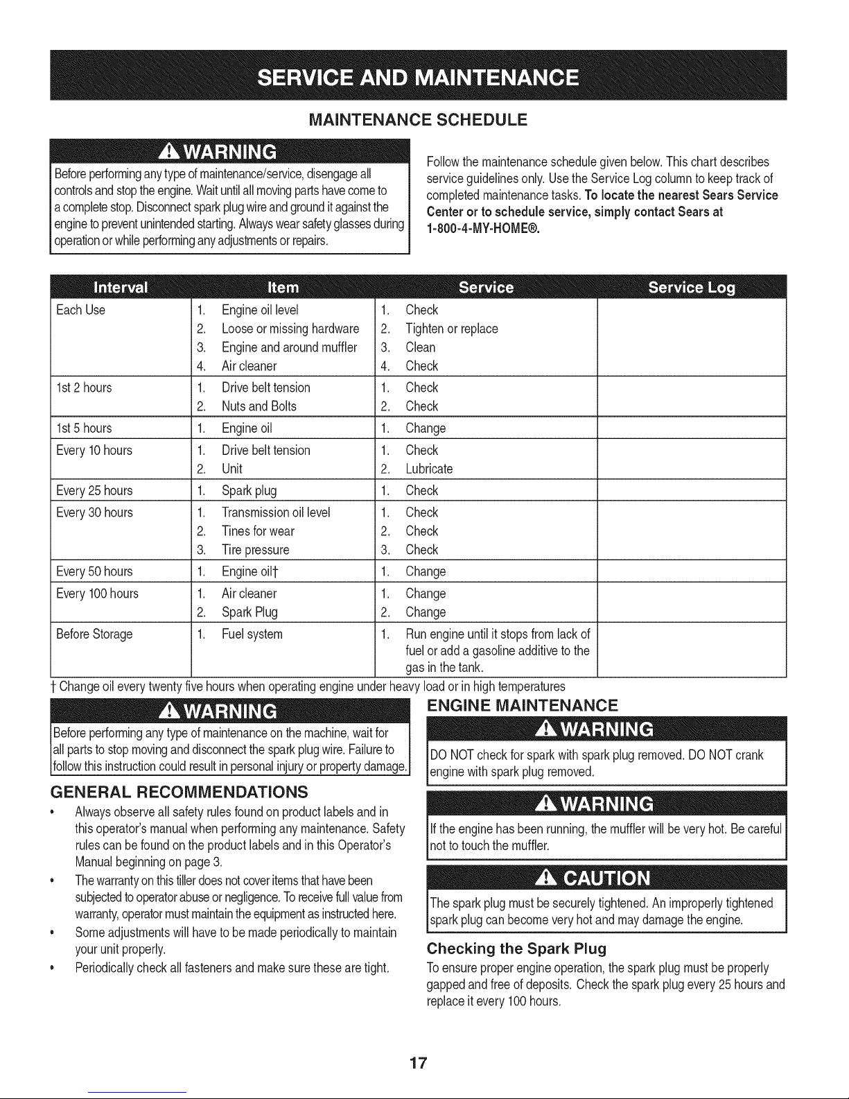
serviceguidelinesonly.UsetheServiceLogcolumnto keeptrackof
completedmaintenancetasks.To locate the nearest Sears Service
Centeror to scheduleservice,simplycontactSearsat
1-800-4-MY-HOME®.
operationor whileperforminganyadjustmentsor repairs.
Followthemaintenanceschedulegivenbelow.Thischartdescribes
= =
EachUse
1st2 hours
1st5 hours
Every10hours
Every25 hours
Every30 hours
Every50 hours
Every100hours
BeforeStorage
1. Engineoillevel
2. Looseormissinghardware
3. Engineandaroundmuffler
4. Aircleaner
1. Drivebelttension
2. Nutsand Bolts
1. Engineoil
1. Drivebelttension
2. Unit
1. Sparkplug
1. Transmissionoillevel
2. Tinesforwear
3. Tirepressure
1. Engineoi11-
1. Aircleaner
2. SparkPlug
1. Fuelsystem
1. Check
2. Tightenor_place
3. Clean
4. Check
1. Check
2. Check
1. Change
1. Check
2. Lubricate
1. Check
1. Check
2. Check
3. Check
1. Change
1. Change
2. Change
1. Runengineuntilit stopsfromlackof
fueloradda gasolineadditivetothe
gasin thetank.
Changeoileverytwentyfivehourswhenoperatingengineunderheavyloadorinhightemperatures
ENGINE MAINTENANCE
Beforeperforminganytypeofmaintenanceon themachine,waitfor
allpartsto stopmovinganddisconnectthe sparkplugwire.Failureto
followthis instructioncouldresultinpersonalinjuryorpropertydamage.
GENERAL RECOMMENDATIONS
• Alwaysobserveallsafetyrulesfoundonproductlabelsandin
thisoperator'smanualwhenperforminganymaintenance.Safety
rulescan befoundonthe productlabelsandin thisOperator's
Manualbeginningon page3.
• Thewarrantyonthistillerdoesnotcoveritemsthathavebeen
subjectedtooperatorabuseornegligence.Toreceivefullvaluefrom
warranty,operatormustmaintaintheequipmentasinstructedhere.
• Someadjustmentswillhaveto be madeperiodicallytomaintain
yourunit properly.
• Periodicallycheckall fastenersand makesurethesearetight.
DONOTcheckforsparkwithsparkplugremoved.DONOTcrank
enginewithsparkplug removed.
Iftheenginehas beenrunning,themufflerwillbeveryhot. Becareful
notto touchthemuffler.
Thesparkplugmustbesecurelytightened.Animproperlytightened
sparkplugcanbecomeveryhot andmaydamagetheengine.
Checking the Spark Plug
Toensureproperengineoperation,thesparkplugmustbeproperly
gappedandfreeof deposits.Checkthe sparkplugevery25hoursand
replaceitevery100hours.
17
Page 18
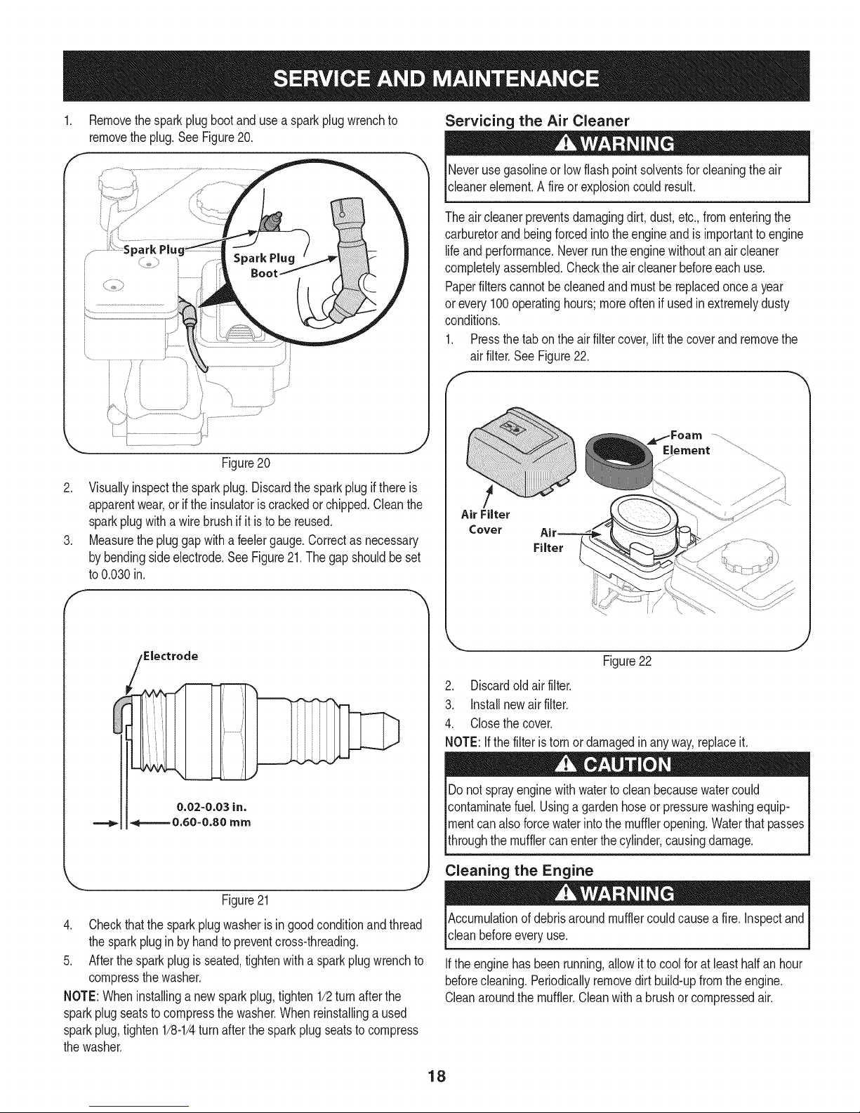
Removethesparkplugbootanduse a sparkplugwrenchto
removetheplug.See Figure20.
Figure20
2. Visuallyinspectthesparkplug.Discardthesparkplugif thereis
apparentwear,orif the insulatoriscrackedorchipped.Cleanthe
sparkplugwitha wirebrush ifit isto be reused.
3. Measurethepluggapwitha feelergauge.Correctas necessary
bybendingsideelectrode.SeeFigure21.The gapshouldbeset
to0.030in.
Servicing the Air Cleaner
Neverusegasolineor lowflashpoint solventsforcleaningtheair
cleanerelement.A fireor explosioncouldresult.
Theaircleanerpreventsdamagingdirt,dust,etc.,fromenteringthe
carburetorandbeingforcedintothe engineandis importanttoengine
lifeandperformance.Neverruntheenginewithoutanair cleaner
completelyassembled.Checktheair cleanerbeforeeachuse.
Paperfilterscannotbecleanedand mustbereplacedoncea year
or every100operatinghours;moreoftenif usedinextremelydusty
conditions.
1. Pressthetab ontheair filtercover,liftthecoverand removethe
air filter.SeeFigure22.
_Foam .....................
Element ............
Air Filter
Cover
Filter
Electrode
0.02-0.03 in.
===_ 4=======0.60-0.80 mm
Figure21
4. Checkthatthe sparkplugwasherisingoodconditionandthread
thesparkplugin by handtopreventcross-threading.
5. Afterthesparkplugis seated,tightenwitha sparkplugwrenchto
compressthewasher.
NOTE:Wheninstallinga newsparkplug,tighten1/2turnafterthe
sparkplugseatsto compressthewasher.Whenreinstallinga used
sparkplug,tighten1/8-1/4turnafterthesparkplugseatsto compress
thewasher.
Figure22
2. Discardoldair filter.
3. installnewair filter.
4. Closethecover.
NOTE:Ifthe filteristornor damagedinany way,replaceit.
Donotsprayenginewithwatertocleanbecausewatercould
contaminatefuel.Usinga gardenhoseor pressurewashingequip-
mentcanalsoforcewaterintothe muffleropening.Waterthatpasses
throughthe mufflercanenterthe cylinder,causingdamage.
Cleaning the Engine
Accumulationofdebrisaroundmufflercouldcausea fire. inspectand
cleanbeforeeveryuse.
Iftheenginehas beenrunning,allow itto coolfor at leasthalf anhour
beforecleaning.Periodicallyremovedirt build-upfromtheengine.
Cleanaroundthemuffler.Cleanwitha brushor compressedair.
18
Page 19
Check Engine Oil
1. Checkoilbeforeeachuse.Stopengineandwaitseveralminutes
beforecheckingoil level.Withthetilleron levelground,theoil
mustbeto FULLmarkon dipstick.
2. Removeoilfill dipstickandwipecleanwithcloth.
3. Replacedipstickintothe oilfillerneck,butdonot screwitin.
Removeandcheckoil level.Levelshouldbeat FULLmark.
4. If needed,addoil slowly- recheck.Donot overfill.
5. Wipedipstickclean,replacebutdonot tighten.Removeand
checkoil level.Oillevelshouldbeat FULLlineondipstick.
6. Replaceandtightendipstickfirmlybeforestartingengine.
Change Engine Oil
DONOTuse non-detergentoilor 2-strokeengineoil.Itcould shorten
theengine'sservicelife.
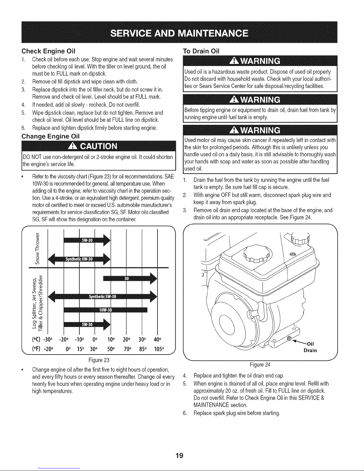
Refertotheviscositychart(Figure23)foroil recommendations.SAE
10W-30is recommendedforgeneral,alltemperatureuse.When
addingoiltotheengine,refertoviscositychartintheoperationsec-
tion.Usea4-stroke,oranequivalenthighdetergent,premiumquality
motoroilcertifiedto meetorexceedU.S.automobilemanufacturer's
requirementsforserviceclassificationSG,SE Motoroilsclassified
SG,SFwillshowthisdesignationonthecontainer.
To Drain Oil
Usedoil isa hazardouswasteproduct.Disposeofusedoil properly
IDo notdiscardwithhouseholdwaste.Checkwithyour localauthori-
lties or SearsServiceCenterforsafedisposal/recyclingfacilities.
Beforetippingengineorequipmentto drainoil, drainfuelfrom
runningengineuntilfuel tankisempty.
Usedmotoroil maycauseskincancerifrepeatedlyleft incontactwith
theskinfor prolongedperiods.Althoughthisisunlikelyunlessyou
handleusedoilon a dailybasis,it isstilladvisabletothoroughlywash
yourhandswithsoapandwateras soonas possibleafterhandling
usedoil.
1. Drainthefuelfromthe tankbyrunningthe engineuntilthe fuel
tankisempty.Besurefuelfill capis secure.
2. WithengineOFFbutstillwarm,disconnectsparkplugwireand
keepitawayfromsparkplug.
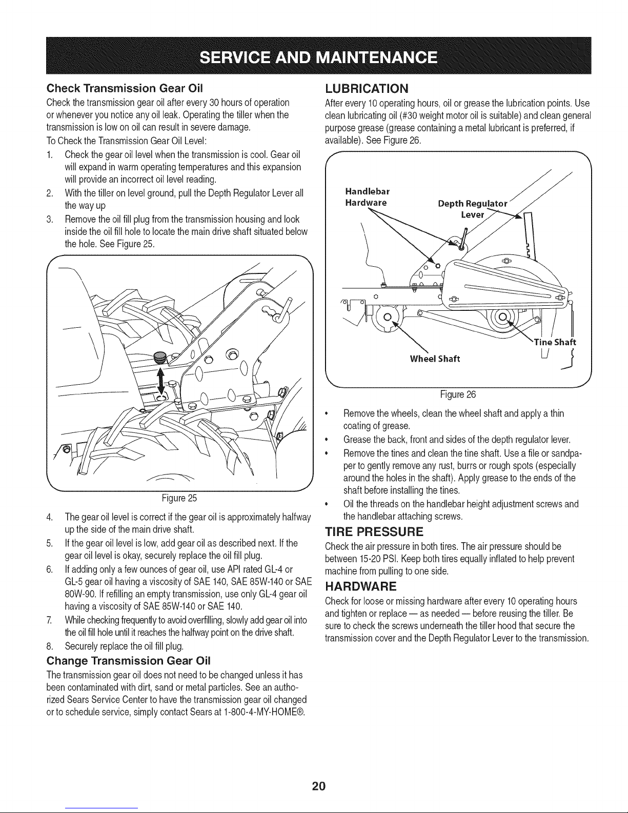
3. Removeoil drainendcap locatedatthe baseof theengine,and
drainoil intoanappropriatereceptacle.See Figure24.
f -,,,
2
I.-
0
m
m
_J _j
_u
uqo_
m
I--
!
m
(°C) -30° -20° -10° 0° 10° 200 300 400
(oF)-20 o 0o 150 300 500 700 850 1050
Figure23
Changeengineoilafterthefirstfiveto eighthoursofoperation,
andeveryfifty hoursoreveryseasonthereafter.Changeoil every
twentyfivehourswhenoperatingengineunderheavyloadorin
hightemperatures.
Drain
Figure24
.
Replaceandtightentheoildrainendcap.
5.
Whenengineisdrainedofall oil, placeenginelevel.Refillwith
approximately20oz.offreshoil. Fillto FULLlineondipstick.
Donot overfill.Referto CheckEngineOilinthis SERVICE&
MAINTENANCEsection.
6. Replacesparkplugwirebeforestarting.
J
19
Page 20
Check Transmission Gear Oil
Checkthetransmissiongearoilafterevery30 hoursofoperation
orwheneveryounoticeanyoil leak.Operatingthe tillerwhenthe
transmissionis lowon oilcan resultin severedamage.
ToChecktheTransmissionGearOil Level:
1. Checkthegearoil levelwhenthetransmissionis cool.Gearoil
willexpandinwarmoperatingtemperaturesandthis expansion
willprovidean incorrectoil levelreading.
2. Withthetiller on levelground,pulltheDepthRegulatorLeverall
thewayup
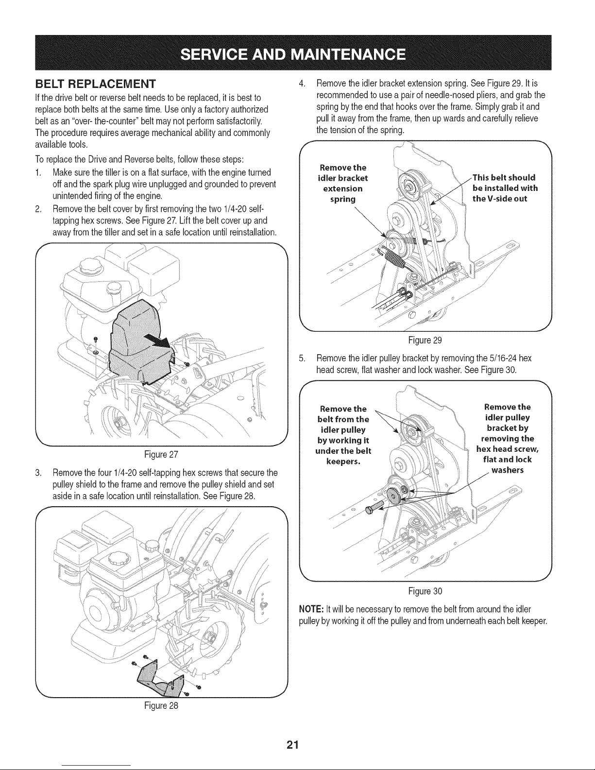
3. Removetheoil fillplugfromthetransmissionhousingand look
insidethe oilfillholeto locatethemaindriveshaftsituatedbelow
thehole.SeeFigure25.
LUBRICATION
Afterevery10operatinghours,oilor greasethelubricationpoints.Use
cleanlubricatingoil (#30weightmotoroilis suitable)andcleangeneral
purposegrease(greasecontaininga metallubricantis preferred,if
available).SeeFigure26.
Handlebar
Hardware Depth Reg_
\
J
Figure25
4. Thegearoil leveliscorrectifthe gearoilisapproximatelyhalfway
uptheside ofthe maindriveshaft.
5. If thegearoil levelislow,addgearoilasdescribednext.Ifthe
gearoillevelis okay,securelyreplacetheoil fillplug.
6. If addingonlya fewouncesof gearoil,useAPIratedGb4 or
Gb5 gearoil havingaviscosityof SAE 140,SAE85%140or SAE
80W-90.ifrefillinganemptytransmission,useonlyGb4 gearoil
havingaviscosityof SAE85W-140or SAE140.
7. Whilecheckingfrequentlytoavoidoverfilling,slowlyaddgearoilinto
theoilfill holeuntilitreachesthehalfwaypointonthedriveshaft.
8. Securelyreplacetheoil fillplug.
Change Transmission Gear Oil
Thetransmissiongearoildoesnot needtobe changedunlessithas
beencontaminatedwithdirt, sandor metalparticles.Seeanautho-
rizedSearsServiceCentertohavethetransmissiongearoil changed
orto scheduleservice,simplycontactSearsat 1-800-4-MY-HOME®.
Tine Shaft
Wheel Shaft
Figure26
• Removethewheels,cleanthe wheelshaftandapplya thin
coatingofgrease.
• Greasetheback,frontandsidesofthe depthregulatorlever.
• Removethetinesandcleanthefine shaft.Usea fileor sandpa-
perto gentlyremoveanyrust,burrsor roughspots(especially
aroundtheholesin theshaft).Applygreaseto theendsofthe
shaftbeforeinstallingthetines.
• Oilthethreadson thehandlebarheightadjustmentscrewsand
thehandlebarattachingscrews.
TIRE PRESSURE
Checktheairpressureinbothtires.Theair pressureshouldbe
between15-20PSI.Keepbothtiresequallyinflatedto helpprevent
machinefrompullingtooneside.
HARDWARE
Checkforlooseor missinghardwareafterevery10operatinghours
andtightenor replace= as needed= beforereusingthetiller.Be
sureto checkthe screwsunderneaththe tillerhoodthat securethe
transmissioncoverandthe DepthRegulatorLevertothetransmission.
2O
Page 21
BELT REPLACEMENT
Ifthedrive beltor reversebeltneedsto be replaced,itis bestto
replacebothbeltsatthe sametime.Useonlya factoryauthorized
beltas an "over-the-counter"beltmaynotperformsatisfactorily.
Theprocedurerequiresaveragemechanicalabilityandcommonly
availabletools.
Toreplacethe DriveandReversebelts,followthesesteps:
1. Makesurethe tillerisona flat surface,withtheengineturned
offandthe sparkplugwireunpluggedandgroundedto prevent
unintendedfiringofthe engine.
2. Removethe beltcoverby firstremovingthetwo1/4-20self-
tappinghexscrews.SeeFigure27.Liftthe beltcoverupand
awayfromthetiller andsetin a safelocationuntilreinstallation.
f
.
Removethe idlerbracketextensionspring.SeeFigure29.It is
recommendedto usea pairof needle-nosedpliers,andgrabthe
springby theendthathooksovertheframe.Simplygrabitand
pull itawayfromthe frame,thenup wardsandcarefullyrelieve
thetensionof thespring.
Remove the
idler bracket
extension
spring
Figure29
5. Removethe idlerpulleybracketbyremovingthe5/16-24hex
headscrew,flatwasherandlockwasher.SeeFigure30.
Figure27
.
Removethe four1/4-20self-tappinghexscrewsthatsecurethe
pulleyshieldtothe frameandremovethepulleyshieldandset
asideina safelocationuntil reinstallation.SeeFigure28.
/
Remove the
belt from the
idler pulley
by working it
under the belt
keepers.
Remove the
idler pulley
bracket by
removing the
hex head screw,
flat and lock
washers
Figure30
NOTE:Itwillbenecessaryto removethebeltfromaroundtheidler
pulleybyworkingitoffthe pulleyandfromunderneatheachbelt keeper.
Figure28
J
21
Page 22
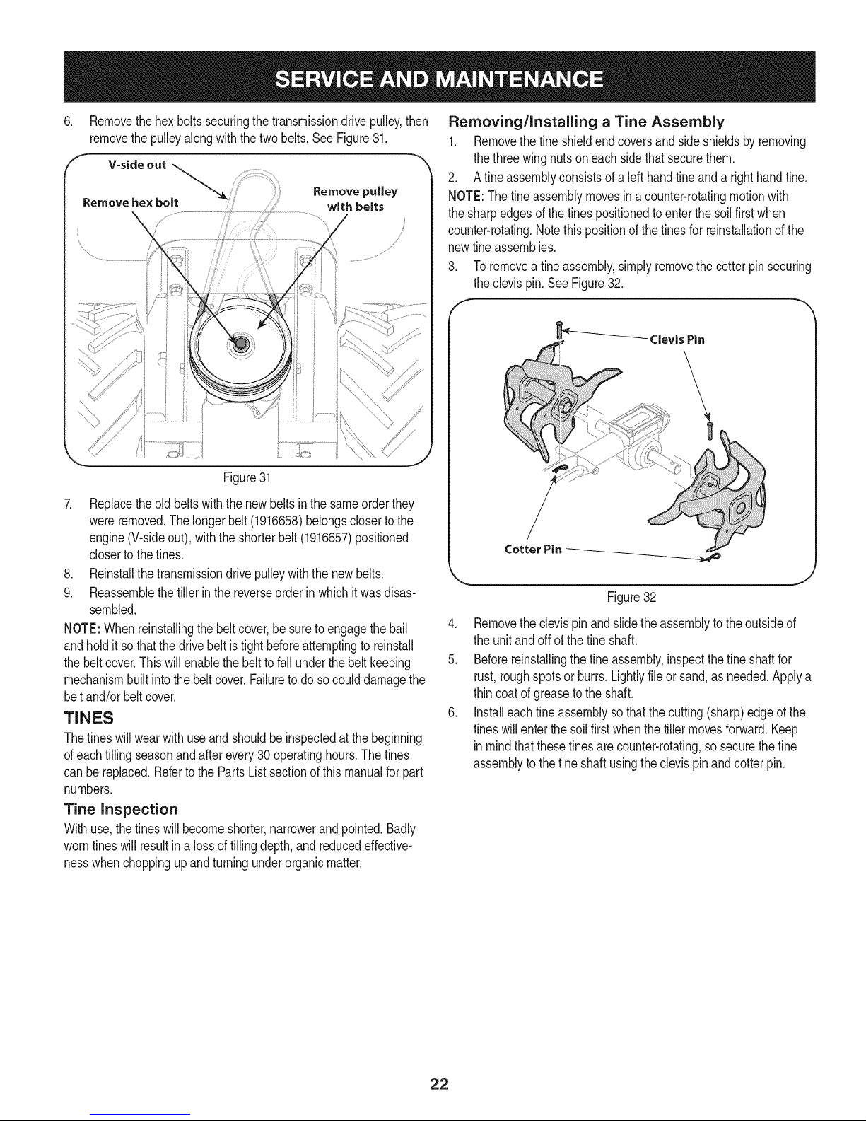
6. Removethehexboltssecuringthetransmissiondrivepulley,then
removethepulleyalongwiththetwobelts. SeeFigure31.
F V-side out
Remove he× bolt with belts
,
Remove pulley
Figure31
7. Replacetheold beltswiththe newbeltsin the sameorderthey
wereremoved.Thelongerbelt (1916658)belongscloserto the
engine(V-sideout),withthe shorterbelt(1916657)positioned
closertothe tines.
8. Reinstallthetransmissiondrive pulleywiththenewbelts.
9. Reassemblethetillerinthereverseorderinwhichitwasdisas-
sembled.
NOTE:Whenreinstallingthebeltcover,besuretoengagethebail
andholditso thatthedrivebeltis tightbeforeattemptingto reinstall
thebeltcover.Thiswill enablethebeltto fall underthebeltkeeping
mechanismbuiltintothebelt cover.Failuretodo socoulddamagethe
beltand/or beltcover.
TINES
Thetineswill wearwithuseand shouldbeinspectedatthe beginning
ofeachtillingseasonandafterevery30 operatinghours.Thetines
canbereplaced.Refertothe PartsListsectionofthismanualforpart
numbers.
Tine Inspection
Withuse,thetineswill becomeshorter,narrowerandpointed.Badly
worntineswill resultin a lossoftilling depth,and reducedeffective-
nesswhenchoppingupandturningunderorganicmatter.
Removing/Installing a Tine Assembly
1. Removethetineshieldendcoversandside shieldsbyremoving
thethreewingnutson eachsidethatsecurethem.
2. A fineassemblyconsistsofalefthandtineanda righthandfine.
NOTE:Thetineassemblymovesinacounter-rotatingmotionwith
thesharpedgesof thetinespositionedtoenterthe soilfirst when
counter-rotating.Notethispositionof thetinesfor reinstallationof the
newfineassemblies.
Toremoveafineassembly,simplyremovethecotterpinsecuring
theclevispin.SeeFigure32.
_' Clevis Pin
Cotter Pin
Figure32
4. Removethe clevispinandslidetheassemblyto theoutsideof
theunit andoffofthe fineshaft.
5. Beforereinstallingthe tineassembly,inspectthefineshaftfor
rust,roughspotsor burrs.Lightlyfileor sand,as needed.Applya
thincoatof greasetotheshaft.
6. Installeachfineassemblysothatthecutting(sharp)edgeof the
tineswillenterthesoilfirstwhenthetillermovesforward.Keep
inmindthatthesetinesare counter-rotating,sosecurethefine
assemblytothefineshaft usingtheclevispinandcotter pin.
22
Page 23

Neverstoretillerwithfuel in tankindoorsorin poorlyventilatedareasI
wherefuel fumesmayreachanopenflame,spark,or pilotlightason
a furnace,waterheater,cothesdryer,orgasapp ance. 1
Neverleaveengineunattendedwhileitis running.
PREPARING THE ENGINE
Enginesstoredbetween30and 90daysneedto betreatedwitha
gasolinestabilizerandenginesstoredover90daysneedto bedrained
offuel topreventdeteriorationandgumfromforminginfuelsystemor
on essentialcarburetorparts.Ifthegasolineinyourenginedeterio-
ratesduringstorage,youmayneedtohavethecarburetor,andother
fuelsystemcomponents,servicedor replaced.
1. Removeallfuel fromtankbyrunningengineuntilit stopsfrom
lackoffuel.
2. Changetheoil.SeeChangeEngineOil inSERVICEAND
MAINTENANCEsection.
3. Removesparkplugand pourabouta 1/2ounceof engineoilinto
thecylinder.Replacesparkplugandcrankit slowlytodistribute
oil.
4. Cleandebrisfromaroundtheengineandthe muffler.Touchup
anydamagedpaint,andcoatotherareasthatmayrustwitha light
filmofoil.
5. Storein aclean,dry andwellventilatedareaawayfromanyap-
pliancethatoperateswitha flameorpilot light,suchasa furnace,
waterheater,orclothesdryer.Alsoavoidany areawitha spark
producingelectricmotor,orwherepowertoolsare operated.
6. Ifpossible,alsoavoidstorageareaswithhighhumidity,because
that promotesrustandcorrosion.
7. Keeptheenginelevelinstorage.Tiltingcancausefuelor oil
leakage.
PREPARING THE TILLER
Whenthe tillerwon'tbeusedforanextendedperiod,prepareitfor
storageasfollows:
1. Cleanthetillerandengine.
2. Followthelubricationrecommendationsandcheckforlooseparts
and hardware.
3. Storethe tillerinaclean,dryarea.
4. Neverstorethetillerwithfuelinthe fueltankinan enclosedarea
wheregas fumescouldreachanopenflameor spark,or where
ignitionsourcesare present(spaceheaters,hotwaterheaters,
furnaces,etc.).
23
Page 24

Beforeperforminganytyped maintenance/service,disengageallcontrolsandstoptheengine.Waituntilall
movingpartshavecometoacompletestop.Disconnectsparkplugwireandgrounditagainsttheenginetoprevent
unintendedstarting.Alwayswearsafetyglassesduringoperationorwhileperforminganyadjustmentsorrepairs.
Enginefailstostart
Enginerunserratically
Engineoverheats
Enginedoesnot shutoff
Wheels/Tineswill notturn
Tinesturn, butwheelsdon't
Wheelsturn,buttinesdon't
Poortillingperformance
1. Sparkplugwire disconnected.
2. EngineThrottleControlLeverincorrectlyset.
3. Fueltankemptyor stalefuel.
4. Dirtyairfilter.
5. Defectiveorincorrectlygappedsparkplug.
6. Misadjustedthrottlecontrol.
7. Dirtorwaterinfueltank.
1. Defectiveorincorrectlygappedsparkplug.
2. Dirtyairfilter(s).
3. Carburetoroutofadjustment.
4. Stalegasoline.
5. Dirtorwaterinfueltank.
6. Enginecoolingsystemclogged.
1. Enginecoolingsystemclogged.
2. Carburetoroutofadjustment.
3. Oillevelis low.
1. Misadjustedthrottlecontrolor ignitionswitch.
1. Improperuseof controls.
2. Worn,broken,or misadjusteddrivebelt(s).
3. Internaltransmissionwearor damage.
4. Boltlooseintransmissionpulley.
1. WheelDrivePinsnotinWHEELDRIVE.
2. Boltlooseintransmissionpulley.
3. Internaltransmissionwearor damage.
1. Tine holdermountinghardwaremissing.
2. Boltlooseintransmissionpulley.
3. Internaltransmissionwearor damage.
1. Worntines.
2. ImproperDepthRegulatorsetting.
3. incorrectthrottlesetting.
4. ForwardDriveBeltslipping.
1. Reconnectwire.
2. Putleverin STARTposition.
3. Filltankwithclean,freshgasoline.
4. Cleanor replacefilter.
5. Clean,adjustgap,or replace.
6. ContactyourSearsParts& RepairCenter.
7. ContactyourSearsParts& RepairCenter.
1. Clean,adjustgap,or replace.
2. Cleanor replace.
3. ContactyourSearsParts& RepairCenter.
4. Replacewithfreshgasoline.
5. ContactyourSearsParts& RepairCenter.
6. Cleanair coolingsystem.
1. Cleanair coolingarea.
2. ContactyourSearsParts& RepairCenter.
3. Checkoil level.
1. Contactyour SearsParts& RepairCenter.
1. ReviewOperationsection.
2. Replaceor adjustbelts.
3. ContactyourSearsParts& RepairCenter.
4. Tightenbolt.
1. InsertsDrivePinsproperly.
2. Tightenbolt.
3. ContactyourSearsParts& RepairCenter.
1. Replacehardware.
2. Tightenbolt.
3. ContactyourSearsParts& RepairCenter.
1. ReplaceTines.
2. See"TillingTips& Techniques."
3. SeeService& MaintenanceSection.
4. SeeService& MaintenanceSection.
NEED MORE HELP?
Youq] [h}d the m_swe_ and mo_}_ on ma_agemy[_eo_em - fear f_'ee!
Find this and air your other product manuats ontine.
Get answers from our team of home experts.
Get a personatized maintenance ptan for your home.
Find information and toots to hetp with home projects.
÷ managemylife
_O_ght te yeI:_ by Sea_s
24
Page 25

25
Page 26

Craftsman Tiller B Model No. 247.299301
8
/
/
2
\
lO
1
\
55
7
/
\
33 27 50
36
\
41
37
40
33
\
\
33
24
8
I
49
\
33
26
Page 27

Craftsman Tiller B Model No. 247.299301
649-04098A-4044
2
686-04135-4044
3
710- 0189
4
710-0599
710-1238
5
710-3288
6
7
712-04063
8 720-0278A Foam Grip, .970 x 11.0
9 731-04735 Selector Handle
10 731-06253A Handle Cover, 400
11 735-04105
12 936-0176
13 736-0242
14 936-0451
15 738-0440
16 946-04504 Reverse Cable
17 946-04506 Forward Cable
18 747-04789-0637 Bail
19 750-0885A Spacer, .322 x .625 x 2.00
Upper Handle Assembly
Reverse Handle Assembly
Hex Screw, 5/16-18 x 3.00
Hex Washer Screw, 1/4-20 x 0.500
Hex Washer Screw, 5/16-18 x .875
Hex Lock Screw, 1/4-20 x 1.62
Flange Lock Nut, 5/16-18
End Plug
Flat Washer, .265 x .938 x .120
Bell Washer, .340 x .872 x .060
Saddle Washer, .320 x .93 x .060
Shoulder Spacer, .375 x .165
20 786-0340B Handle Adjustment Crank
21 786-04344-4044 RH Handle Bracket
22. 786-04345-4044 LH Handle Bracket
23 786-04346 400 Nut Retainer Bracket
24 786-04360-4044 Front Bumper
25 731-06529 Belt Cover
26 736-0173 Flat Washer, .28 x .74 x .063
27 786-04356-4044 Depth Adjustment Bracket
28 686-0044B-4044 End Cover Assembly
29 710-0597 Hex Screw, 1/4-20 x 1.00
710-0604A Hex Washer Screw, 5/16-18 x 0.625
31 710-1238 Hex Washer Screw, 5/16-18 x .875
32 710-3008 Hex Screw, 5/16-18 x .75
33 712-04063 Flange Lock Nut, 5/16-18
34 712-04064 Flange Lock Nut, 1/4-20
35 712-04065 Flange Lock Nut, 3/8-16
36 712-0421 Wing Nut w/Bell Washer, 5/16-18
37 715-0108 Spring Pin, 1/4 x 1.00
38 926-0106 Cap Speed Nut, 1/4
39 731-05512 Deck Hole Plug
40 732-04320 Torsion Spring
41 738-04320 Shoulder Screw, 5/16-18 x .405 x .345
42 938-0533 Shoulder Screw, .498 x 1.635
43 938-0849 Hex Screw, 5/16-18 x .75
44 747-0432 Tiller Flap Rod
45 750-05349 Round Spacer, .370 x .260 x .410
46 786-0090A-4044 Side Shield
47 786-0113A-4044 Rear Tine Shield
48 786-04092-4044 Stop Reverse Arm
49 786-04104-4044 Depth Drag Bar
50 786-04352A-4044 Tine Shield Mount Bracket
51 786-04355A-4044 Tine Shield
52 786-04363-4044 LH Tail Bracket
53 786-04364-4044 RH Tail Bracket
54 720-04173 Reverse Handle Grip
55 710-0502A Hex Washer Screw, 3/8-16 x 1.250
56 710-0896 Hex Washer Screw, 3/8-16 x 1.250
57 952Z170-TU Replacement Engine
27
Page 28

Craftsman Tiller B Model No. 247.299301
34
38
33
7
19
12
29
18
\
15
32
28
Page 29

Craftsman Tiller B IViodel No. 247.299301
934-04652 CompleteWhl.Assy.,13x5 x6 (B,C)
2 714-0143A Click Pin
3 684-04168 Idler PulleyAssembly
4 710-0151 Hex Screw,3/8-24x2.00 25
5 710-0170 Hex Screw,5/16-24x .625 26
6 710-0599 SelfTappingScrew,1/4-20x .500 27
7 710-0606 Hex Screw,1/4-20x 1.50 28
8 710-0672 HexScrew,5/16-18x 1.25 29
9 710-1880 HexScrew,5/16-18x .75,Patch 30
10 918-04815A TransmissionAssembly 31
11 712-04064 HexLockNut,1/4-20 32
12 712-0700 Nut,9/16-18,FlangeLock 33
13 718-04407 Hub, 5/8Spline 34
14 732-04085 ExtensionSpring,.480ODX 5.00LG 35
15 732-04276A ExtensionSpring,LT5PTO 36
16 936-0119 LockWasher,5/16 37
17 736-0173 Washer,.28x .74x .063 38
18 714-04043 InternalCotterPin 39
19 736-0343 FlatWasher,.330X 1.25X .120 40
20 936-0452 BellWasher,.396x 1.140x .095
21 736-3092 FlatWasher,.265x 1.0x .030
23 748-04087A PivotIdlerSpacer
24 750-04571 ShoulderSpacer,.260x .785x .538
42 736-0315 FlatWasher,.760x 1.500x.120
738-04425 ShoulderScrew,.342x .3351/4-28
750-04907 PivotIdlerSpacer
954-04090 V-Belt
954-04091 V-Belt
756-04198A EnginePulley
756-04355 TransmissionPulley
756-0625 CableRoller
786-04312 IdlerBracket,Forward
786-04343-4044 CoverPlate
786-04346
786-04416A-4044
786-04415B-4044
786-04357-4044
786-04371-4044
642-04071-4044
642-04072-4044
911-0415
41 710-0896 HexWasherScrew,1/4-14x .625
IdlerBracket,Reverse
MountingFrame,RH
MountingFrame,LH
PulleyBracket
PulleyShield
TineAssembly,LH
TineAssembly,RH
ClevisPin,.375x 1.75
29
Page 30

Craftsman Tiller B Model No. 247.299301
12
2
6
i iT
18
19
2o \
17 18
21
7
14
11
\
4
14
7
21
1o
6
\
\
3O
Page 31

Craftsman Tiller B IViodel No. 247.299301
918-04815A TransmissionAssembly
1 919-04184A Housing,Transmission
2 710-3008 HexScrew,5/16-18,.75,Gr5
3 911-04844 Shaft,Tiller
4 911-04854 Shaft,Wheel
5 911-05028 Shaft,Worm
6 714-04059 Key, HiPro.25x 1.062
7 716-0204 Retaining Ring
8 716-04102 RetainingRing,Int
9 917-04380 WormGear,61t,RH
10 917-04381 WormGear,30t,LH
11 918-04435 BearingCover
12 921-04030 Seal,Oil,.750Shaftx 1.783Bore
13 921-04229 Gasket,GearHousing
14 721-04232 Seal,Oil,1.00Shaftx 2.00 Bore
15 721-04271 RubberPlug,Oil
16 732-0614 WireRing
17 736-04305*
-- 736-04306"
-- 736-04307"
-- 736-04308"
18 736-0745
19 941-04298
20 941-04299
21 741-3114
22 786-04366 Cover,Transmission
23 786-04392 Cover,Transmission
* Theflatwasherslistedareusedas requiredtoobtain.005to .015
inallowableendplayonthedriveshaft.
D = t
Washer,Flat,1.50x 1.75x .062
Washer,Flat,1.50x 1.75x .005
Washer,Flat,1.50x 1.75x .03
Washer,Flat,1.50x 1.75x .010
Washer,Flat,1.010x 1.56x .060
ConeBearing
BearingCup
Ball Bearing
31
Page 32

Craftsman Engine Model 170=TU For Tiller Model 247.299301
32
m
!
t
i32
!
t
133
i
i
i
134
i
i
i
i35
!
t
137
i
i
i
i38
!
!
t
139
i
i
140
i
i
i
i41
!
t
i
142
i
i43
951-10806
712-04213
951-14068
951-14069
951-14070
750-05314
951-10794
951-14071
951-14072
951-14073
951-14074
41
33
D = 0
AirCleanerHousing
Nut
Self-TappingBoltM4.2x16
CarbonCanister
SilencerPlate
RubberShockPad
AirFilterAssembly
AirFilterCover
PrimerHose
Clamp
ExhaustPiping
32
Page 33

Craftsman Engine IViodel 170=TU For Tiller IViodel 247.299301
3_
d
I
m
n
m
26
27
28
29
30
31
127
a
b
C
d
e
f
g
h
I
710-05101
951-11567
951-11568
951-11569A
951-12124
951-11571
951-12119A
951-11177
n/a
n/a
n/a
n/a
n/a
736-04638
n/a
n/a
127- Carburetor Kit- Major
D = O O
StudM6x110
CarburetorInsulatorGasket
CarburetorInsulator
CarburetorGasket
CarburetorAssembly
CarburetorGasketPlate
CarburetorKit- Major
ControlLever,Choke
ChokeShaft
ChokePlate
ThrottleShaft
ThrottlePlate
ScrewM3x5
LockWasher
IdleJetAssembly
Gasket,ThrottlePlate
m
J
k
I
m
n
O
P
q
r
s
t
U
V
W
X
n/a
n/a
n/a
n/a
n/a
n/a
n/a
n/a
n/a
951-11589
n/a
951-11348
710-04945
951-11349
710-04938
D = O O
IdleSpeedAdjustingScrew
MixtureScrew
CarburetorBody
FloatPin
EmulsionTube
NeedleValve
MainJet
NeedleValveSpring
Float
FuelBowlGasket
FuelBowl
FuelBowlGasket
FuelBowlMountingBolt
FuelDrainPlugGasket
FuelDrainPlug
33
Page 34

Craftsman Engine IViodel 170=TU For Tiller IViodel 247.299301
3
125- GasketKit- External
125- GasketKit- Complete
130- Complete Engine
510
52
74 74
34
Page 35

Craftsman Engine IViodel 170=TU For Tiller IViodel 247.299301
m
5O
51
52
53
54
55
56
57
58
59
6O
61
62
63
64
65
66
67
68
69
70
71
72
73
74
77
125
951-12111
951-11632
951-12007
951-11633
710-04915
951-11113
951-11573
951-11356
736-04461
951-11574
714-04074
951-11575
951-11369
951-12160
951-10307
951-11576
715-04092
715-04089
951-11371
951-12125
710-04932
951-11283
951-11578
951-12551
951-12514
951-12126
951-12573
m = O O
PistonRingSet
PistonPinSnapRing
Piston
PistonPin
BoltM6x12
Air Shield
ConnectingRodAssembly
GovernorArm Shaft
Washer5.2xl.9
GovernorSeal
CotterPin
CamshaftAssy.
RadialBallBearing,6205
CrankshaftAssembly
WoodruffKey
GovernorGear/ShaftAssembly
DowelPin7x14
DowelPin9x14
CrankcaseCoverGasket
CoverComp,LeftCrankcase
BoltM8x32
OilPlug
OilSeal,25x41.25x6
ShortBlock
(Incl.6,22,27,28,44,46,47,
50-53,56-70,72-75)
OilDrainPlug
OilSeal25x41.25x6
GasketKit- External
126
130
951-12572
952Z170_U
(Incl.6,22,27-29,31)
GasketKit- Complete
(Incl.6,22,27-29,31,44,
58,59,68,72,75)
CompleteEngine
35
Page 36

Craftsman Engine IViodel 170=TU For Tiller IViodel 247.299301
18
124
\
7
36
Page 37

Craftsman Engine IViodel 170=TU For Tiller IViodel 247.299301
m
1
2
3
4
6
7
8
9
10
11
12
13
14
15
16
17
18
19
710-04968
951-11054
726-04101
731-07059
951-11565
951-11892
751-11124
751-11123
951-11893
710-04902
951-11895
951-12000
951-12002
951-12003
951-12004
951-11894
710-04933
951-10819
D = B 0
BoltM6x16
ValveCover
BreatherHoseClamp
ExhaustPiping
ValveCoverGasket
RockerArmAssembly
Nut,PivotLocking
AdjustingNut,Valve
RockerArm
Bolt,Pivot
PushRodGuide
Retainer,In.ValveSpring
Adjuster,ExhValve
Retainer,Ex.ValveSpring
ValveSpring
IntakeValveSeal
BoltM8x55
CylinderHeadServiceKit
m
2O
44
45
46
47
48
49
124
125
126
130
951-10722A
951-10292
951-11572
951-10648
951-11899
715-04108
951-10647A
951-10647A
951-11063A
951-12573
951-12572
952Z170-TU
D = " O O
Incl.4,15,16,38)
CylinderHeadAssembly
(Incl.6,8-17,19,22,28,
29,44,48,49)
SparkPlug/F6Rtc
Gasket,CylinderHead
PushRodKit
Tappet
DowelPin10x16
ValveKit
ValveKit
ValveCoverKit
GasketKit- External
(Incl.6,22,27-29,31)
GasketKit- Complete
(Incl.6,22,27-29,31,44,
58,59,68,72,75)
CompleteEngine
37
Page 38

Craftsman EngineModel 170=TUFor Tiller Model 247.299301
_122
m
75
76
78
79
8O
81
82
83
84
86
87
88
89
122
123
951-11110
710-04940
951-10792
710-04919
951-10805
951-10934
951-10911
712-04209
710-04915
951-11583
736-04455
710-04974
951-12418
710-04918
951-11109
D = " O O
Air FlowShield
BoltM6xlO
IgnitionCoilAssembly
BoltM6x25
Flywheel
Fan,Cooling
Pulley,Starter
Nut,Special,M14x1.5
BoltM6x12
BlowerHousing
Washer
BoltM6xlO
RecoilStarter
BoltM6x20
BlowerHousingShield
38
Page 39

Craftsman Engine IViodel 170=TU For Tiller IViodel 247.299301
_111_107
106--_ ¢05
los
lO_ 11_
98
9_ 93
11oJ
_112
_--119
m
1
3
90
91
92
93
94
95
97
98
99
100
101
102
103
14
710-04968
726-04101
951-11067
951-12131
710-05103
951-11585
951-10664
951-10665
951-11106
712-04212
710-04908
951-10650
951-11700
710-04915
951-14075
m = B II
BoltM6x16
BreatherHoseClamp
ThrottleControlKnob
PrimerBracket
BoltM6x12
GovernorSpring
ThrottleLinkageSpring
ThrottleLinkage
GovernorArm
NutM6
GovernorArmBolt
FuelLineKit
FuelHoseClamp
BoltM6x12
RolloverValve
104
105
106
107
108
109
110
111
112
113
114
118
119
120
121
12o
951-11914
710-04905
710-04915
951-12482
951-11381
951-11913
951-11904
951-11912
951-12535
951-14076
751-14139
951-14077
951-11933
951-10651
712-04212
_114
D = I! O
DipstickDecorationCover
Bolt
BoltM6x12
DipstickAssembly
O-Ring
Oil FillTube Assembly
O-Ring
DipstickGuage
CapComp,Fuel
Tether
PrimerHose
FuelTankAssembly
FuelLevelIndicator
FuelTankNipple
Nut,M6
39
Page 40

Craftsman Engine IViodel 170-TU For Tiller IViodel 247.299301
m
21
22
23
24
25
951-14063
951-11289
712-04214
951-14067
951-12865
D = = O O
StudM8x38
ExhaustPipeGasket
Nut,M8
MufflerAssembly
SecondaryAirValve
4O
Page 41

Craftsman Tiler IViodel No. 247.299301
777S33496 777D15447
777123259
777S33612
777X45317
777D15452
777D15444
777i22969 777122968
777123174
WHEELS
REVERSE
YINES
FORWARDi
41
Page 42

(Thispageapplicableinthe U.S.A.and Canadaonly.)
Sears Brands Management Corporation (Sears), the California Air Resources Board (CARD)
and the United States Environmental Protection Agency (U.S. EPA)
Emission Control System Warranty Statement (Owner's Defect Warranty Rights and Obligations)
EMISSIONCONTROLWARRANTYCOVERAGEISAPPLICABLETOCERTI-
FIEDENGINESPURCHASEDINCALIFORNIAIN1995ANDTHEREAF-
TER,WHICHAREUSEDINCALIFORNIA,ANDTOCERTIFIEDMODEL
California and United States Emission
TheCaliforniaAirResourcesBoard(CARD),U.S.EPAand Searsarepleased
toexplainthe EmissionControlSystemWarrantyonyour modelyear2000and
latersmalloff-roadengine(SORE).InCalifornia,newsmalloff-roadengines
mustbe designed,builtand equippedto meettheState'sstringentanti-smog
standards.Elsewherein theUnitedStates,newnon-road,spark-ignition
enginescertifiedformodelyear1997and latermustmeetsimilarstandardsset
forthbythe U.S.EPA.Searsmustwarranttheemissioncontrolsystemonyour
YEAR1997ANDLATERENGINESWHICHAREPURCHASEDANDUSED
ELSEWHEREINTHEUNITEDSTATES(ANDAFTERJANUARY1,2001 IN
CANADA).
Control Defects Warranty Statement
enginefortheperiodsoftime listedbelow,providedtherehasbeennoabuse,
neglector impropermaintenanceofyoursmalloff-roadengine.Youremis-
sioncontrolsystemincludespartssuchasthecarburetor,aircleaner,ignition
system,mufflerandcatalyticconverter.Alsoincludedmaybeconnectorsand
otheremissionrelatedassemblies.Whereawarrantableconditionexists,Sears
will repairyoursmalloff-roadengineatnocostto youincludingdiagnosis,parts
andlabor.
Sears Emission Control Defects Warranty Coverage
Smalloff-roadenginesarewarrantedrelativeto emissioncontrolpartsdefects
fora periodofone year,subjecttoprovisionssetforthbelow.Ifanycovered
Owner's Warranty
Asthe smalloff-roadengineowner,youare responsiblefortheperformanceof
therequiredmaintenancelistedin yourOperatingand MaintenanceInstruc-
tions.Searsrecommendsthatyouretainallyourreceiptscoveringmaintenance
onyoursmalloff-roadengine,butSearscannotdenywarrantysolelyforthe
lackofreceiptsorforyourfailuretoensuretheperformanceof allscheduled
maintenance.Asthe smalloff-roadengineowner,youshouldhoweverbe
awarethat Searsmaydenyyouwarrantycoverageifyoursmalloff-roadengine
ora parthasfaileddueto abuse,neglect,impropermaintenanceor unap-
parton yourengineis defective,thepart willbe repairedorreplacedbySears.
Responsibilities
provedmodifications.Youareresponsiblefor presentingyoursmalloff-road
engineto anAuthorizedSearsServiceDealerassoonas aproblemexists.The
undisputedwarrantyrepairsshouldbecompletedina reasonableamountof
time,notto exceed30days.Ifyouhaveanyquestionsregardingyourwarranty
rightsandresponsibilities,youshouldcontacta SearsServiceRepresentative
at 1-800-469-4663.Theemissionwarrantyisa defectswarranty.Defectsare
judgedonnormalengineperformance.The warrantyis notrelatedtoan in-use
emissiontest.
Sears Emission Control Defects Warranty Provisions
ThefollowingarespecificprovisionsrelativetoyourEmissionControlDefectsWarrantyCoverage.ItisinadditiontotheSearsenginewarrantyfornon-regulated
enginesfoundin theOperatingandMaintenanceInstructions.
1. WarrantedParts
Coverageunderthiswarrantyextendsonlytothe partslistedbelow(the
emissioncontrolsystemsparts)to the extentthesepartswerepresenton
theenginepurchased.
a. FuelMeteringSystem
• Cold startenrichmentsystem
• Carburetorandinternalparts
• FuelPump
b. AirlnductionSystem
• Aircleaner
• Intakemanifold
c. IgnitionSystem
• Sparkplug(s)
• Magnetoignitionsystem
d. CatalystSystem
• Catalyticconverter
• Exhaustmanifold
• Air injectionsystemorpulsevalve
e. MiscellaneousItemsUsedin AboveSystems
• Vacuum,temperature,position,timesensitivevalves
andswitches
• Connectorsandassemblies
2. Lengthof Coverage
Searswarrantsto theinitialownerand eachsubsequentpurchaserthat
theWarrantedPartsshallbefree fromdefectsin materialsandworkman-
shipwhich causedthefailureofthe WarrantedPartsfor aperiodof one
yearfromthe datetheengineis deliveredtoa retailpurchaser.
Inthe USAandCanada,a 24hourhotline,1-800-469-4663,hasa menuofpre-recordedmessagesofferingyouenginemaintenanceinformation.
3. NoCharge
Repairorreplacementof anyWarrantedPartwillbe performedat no
chargeto the owner,includingdiagnosticlaborwhichleadstothe
determinationthata WarrantedPartisdefective,ifthediagnosticwork is
performedatanAuthorizedSearsServiceDealer.Foremissionswarranty
servicecontact yournearestAuthorizedSearsServiceDealeras listedin
the "YellowPages"under"Engines,Gasoline,""GasolineEngines,""Lawn
Mowers,"orsimilarcategory.
4. Claimsand CoverageExclusions
Warrantyclaimsshallbefiled inaccordancewiththe provisionsofthe
SearsEngineWarrantyPolicy.Warrantycoverageshallbeexcludedfor
failuresof WarrantedPartswhicharenotoriginalSears partsor because
ofabuse,neglector impropermaintenanceassetforth intheSears
EngineWarrantyPolicy.Searsisnotliableto coverfailuresof Warranted
Partscausedby theuseof add-on,non-original,or modifiedparts.
5. Maintenance
AnyWarrantedPartwhichis notscheduledforreplacementasrequired
maintenanceor whichis scheduledonlyforregularinspectionto the effect
of"repairor replaceasnecessary"shallbe warrantedasto defectsfor the
warrantyperiod.AnyWarrantedPartwhichis scheduledfor replacement
asrequiredmaintenanceshallbewarrantedas todefectsonly forthe
periodoftime uptothe firstscheduledreplacementforthat part.Any
replacementpartthat isequivalentinperformanceanddurabilitymay
beusedinthe performanceofanymaintenanceor repairs.Theowneris
responsiblefortheperformanceof all requiredmaintenance,asdefinedin
the SearsOperatingandMaintenanceInstructions.
6. ConsequentialCoverage
Coveragehereundershallextendto thefailure ofanyenginecomponents
causedbythefailureofanyWarrantedPartstill underwarranty.
GDOC-100188Rev.B
42
Page 43

Look For Relevant Emissions Durability Period and
Air index information On Your Engine Emissions Label
Engines that are certified to meet the California Air Resources Board (CARB) Tier 2 Emission Standards must
display information regarding the Emissions Durability Period and the Air Index. Sears Brands Management
Corporation makes this information available to the consumer on our emission labels.
The Emissions Durability Period describes the number of hours of actual running time for which the engine is
certified to be emissions compliant, assuming proper maintenance in accordance with the Operating & Mainte-
nance Instructions. The following categories are used:
Moderate: Engine is certified to be emission compliant for 125 hours of actual engine running time.
Intermediate: Engine is certified to be emission compliant for 250 hours of actual engine running time.
Extended: Engine is certified to be emission compliant for 500 hours of actual engine running time.
For example, a typical walk-behind lawn mower is used 20 to 25 hours per year. Therefore, the Emissions
Durability Period of an engine with an intermediate rating would equate to 10 to 12 years.
The Air index is a calculated number describing the relative level of emissions for a specific engine family. The
lower the Air Index, the cleaner the engine. This information is displayed in graphical form on the emissions label.
After July 1,2000, Look For Emissions Compliance Period
On Engine Emissions Compliance Label
After July 1, 2000 certain Sears Brands Management Corporation engines will be certified to meet the United
States Environmental Protection Agency (USEPA) Phase 2 emission standards. For Phase 2 certified engines, the
Emissions Compliance Period referred to on the Emissions Compliance label indicates the number of operating
hours for which the engine has been shown to meet Federal emission requirements.
For engines less than 225 cc displacement, Category C = 125 hours, B = 250 hours and A = 500 hours.
For engines of 225 cc or more, Category C = 250 hours, B = 500 hours and A = 1000 hours.
This is a generic representation of the emission label typically found on a certified engine.
FAMILYYBSXS.3192VA 274812
GDOC-100182Rev.B
43
Page 44

Congratulations on making a smart purchase. Your new Craftsman® product is designed and
manufactured for years of dependable operation. But like all products, it may require repair
from time to time. That's when having a Repair Protection Agreement can save you money and
aggravation.
Here's what the Repair Protection Agreement* includes:
[] Expert service by our 10,000 professional repair specialists
[] Unlimited service and no charge for parts and labor on all covered repairs
[] Product replacement up to $1500 if your covered product can't be fixed
[] Discount of 25% from regular price of service and related installed parts not covered by the
agreement; also, 25% off regular price of preventive maintenance check
[] Fast help by phone - we call it Rapid Resolution - phone support from a Sears representative.
Think of us as a "talking owner's manual."
Once you purchase the Repair Protection Agreement, a simple phone call is all that it takes for you
to schedule service. You can call anytime day or night, or schedule a service appointment online.
The Repair Protection Agreement is a risk-free purchase. If you cancel for any reason during the
product warranty period, we will provide a full refund. Or, a prorated refund anytime after the
product warranty period expires. Purchase your Repair Protection Agreement today!
Some limitations and exclusions apply. For prices and additional information in the U.S.A.
call 1=800=827=6655.
*Coverage in Canada varies on some items. For full details call Sears Canada at 1=800=361=
6665.
Sears Installation Service
For Sears professional installation of home appliances, garage door openers, water heaters, and
other major home items, inthe U.S.A. or Canada call 1=800=4=MY=HOME®.
44
Page 45

Declaraci6n de garantia ........................ Pb,gina 45
Medidas importantes de seguridad ..... Pb,ginas 46-49
Armado ................................................. Pb,ginas 50-53
Funcionamiento .................................... Pb,ginas 54-59
Servicio y Mantenimiento ..................... P_.ginas 60-65
Almacenamiento fuera de temporada.. Pb,gina 66
Soluci6n de problemas ......................... P_,gina 67
Acuerdo de protecci6n para reparaciones Pb,gina 71
NQmero de servicio ............................... Cubierta posterior
CRAFTSMAN DOS AltOS DE GARANTJA
Durantedosa_osdesdela fechade compra,esteproductoestAgarantizadocontracualquierdefectodematerialeso manodeobra.Un
productodefectuosorecibir_lareparaci6no sustituci6ngratuitasi la reparaci6nnoest_disponible.
Paradetalles sobre lagarantia de coberturaparaobtener reparaci6ngratuita o reemplazo,visite elsitio web: www.craftsman.com
Esta garantias61ocubre defectos enrnateriaiesy manode obra. Cobertura de lagarantiano ineiuye:
• Bienesfungiblesquepuedendesgastarseconel usonormalenel periodode garantia,comolas cuchillas,dientes,ocinturones.
• DaSosenel productoresultantede losintentosdel usuariodemodificaci6ndel productoola reparaci6no causadosporaccesoriosde
productos.
• Las reparacionesnecesariasdebidoa un accidenteo fallaparaoperaro mantenerel productoseg0nlasinstruccionessuministradas.
• Mantenimientopreventivoo reparacionesnecesariasdebidoa la mezcladecombustibleinadecuado,eJcombustiblecontaminadoo viciado.
Estagaranfiaseranulasiel productoes utilizadoalgunavez,mientrasquela prestaci6nde servicioscomercialo sise alquilaa otrapersona.
Estagaranfiale otorgaderechoslegalesespecificos,y ustedtambi_npuedetenerotrosderechosquevariandeestadoaestado.
Sears Brands Management Corporation, Hoffman Estates, IL 60179
Seriedel motor: 208cc
Tipodeaceitedelmotor: 10W30
Capacidadde aceitedel motor: 20onzas
Combustible: GasoJinasinplomo
Bujia: F6RTC
Separaci6ndelas bujias: .030"
NSmerode modelo ..........................................................
NSmerode serie..............................................................
Fechade compra .............................................................
Registreeln0merodemodelo,nQmerode serie
y fechade compram_sarriba
@SearsBrands,LLC 45
Page 46

Lapresenciadeestesimboloindicaquesetratadeinstruccionesde
seguridadimportantesquesedebenrespetarparaevitarponerenpeligro
suseguridadpersonaly/omaterialyladeotraspersonas.Leaycumpla
todaslasinstruccionesdeestemanualantesdeintentaroperaresta
m&quina.Sinorespetaestasinstruccionespuedeprovocarlesiones
personales.Cuandoveaestesimbolo,ipresteatenci6nalaadvertencia!
Estam&quinaest&diseSadaparaserutilizadarespetandolasnormas
deseguridadcontenidasenestemanual.AIigualqueconcualquiertipo
deequipomotorizado,undescuidooerrorporpartedeloperadorpuede
producirlesionesgraves.Estam_quinaescapazdeamputardedos,
manosypiesydearrojarresiduos.Denorespetarlasinstruccionesde
seguridadsiguientessepuedenproducirlesionesgravesolamuerte.
PROPOSICION 65 DE CALiFORNiA
Elescapedel motorde esteproducto,algunosde suscomponentesy
algunoscomponentesdelvehiculocontieneno liberansustanciasquimicas
queel estadode Californiaconsideraque puedenproducircancer,
defectosdenacimientou otrosproblemasreproductivos.Loshomesdela
bateriaylos accesoriosalinescontienenplomoy compuestosde plomo,
sustanciasquimicasque segQnIoestablecidoporel Estadode California
causanc&ncery daSosen elsistemareproductivo.L&veselas manos
despuesdeestarencontactoconestoscomponentes.
CAPACITACION
• Lea,cornprenday respetetodaslasinstruccionesquefiguranen
la rn_.quinayen el o losrnanualesantesde procederaarrnarlay
hacerlafuncionar.Guardeestemanualenun lugarseguropara
consultasfuturasy peri6dicas,asicornoparasolicitarrepuestos.
• Leael manualdeloperadory sigatodaslasadvertenciase
instruccionesdeseguridad.Denohacerlo,puedeocasionar
heridasdegravedadal operadory/oa losobservadores.Ante
cualquierduda,Ilarneal1-800-4MY-HOME.
• Farniliaricesecontodoslos controlesysucorrecto
funcionarniento.Sepac6rnodetenerla rn_.quinay c6rno
desconectarloscontrolesr_.pidarnente.
• No perrnitanuncaque losni_os rnenoresde 14a_osutilicen
estarn_.quina.Los ni_osde 14a_osenadelantedebenleery
entenderlasinstruccionesde operaci6nynorrnasdeseguridad
contenidasen estemanualyen larn_.quinay debenser
entrenadosy supervisadosporun adulto.
• Nuncaperrnitaquelosadultosoperenestarn_quinasinrecibir
antesla instrucci6napropiada.
• Mantengaalos observadores,rnascotasyni_osal rnenosa25
metrosdela rn_.quinarnientrasest,.en funcionarniento.Detenga
la rn_.quinasi alguienseacerca.
• Nuncaenciendael motorenespacioscerradosoenunazona
conpocaventilaci6n.Elescapedel motorcontienernon6xidode
carbono,un gasinodoroy letal.
Su responsabilidad--Lirnite el usodeestarn_.quinarnotorizada
alas personasquelean,cornprendany curnplanlasadvertenciase
instruccionesqueaparecenenestemanualyen larn_.quina.
i6UARI)E ESTASINSTRUCCIONES!
PREPARATIVOS
• Reviserninuciosarnenteel &readondeseva a usarel equipo.
Retiretodaslaspiedras,botellas,latasy otrosobjetosextra_os
que puedanserlevantadoso arrojadoscausandolesiones
personaleso da_osa larn_.quina.
• Paraprotegerselosojos,utilicesiernpregalas o anteojosde
seguridadrnientrasoperala rn_.quinao rnientraslaajustao
repara.Losobjetosarrojadosquerebotanpuedenproducir
lesionesocularesgraves.
• Utilicezapatosdetrabajoresistentes,desuelafuerte,y
pantalonesycarnisasajustados.Lasprendassueltasy las
alhajasse puedenengancharen las piezasrn6viles.Nuncaopere
estarn_.quinaestandodescalzooconsandalias.
• Antesde encenderla rn_quinacontrolequetodoslospernosy
tornillosest_nbienajustadosparagarantizarquela rn_.quinase
encuentraen condicionessegurasdeoperaci6n.Adern_.s,realice
una inspecci6nvisualde la rn_.quinaa intervalosfrecuentespara
controlarsila rnisrnaest,.da_ada.
• Antesde arrancarel motor,desenganchelas palancasdel
ernbragueydespl_.celas(en casode haber)a la posici6nneutral
("N").
• Nuncadejelarn_.quinaen funcionarnientosinvigilancia.
• Nuncaintenterealizarajustesrnientrasel motorest,.enrnarcha,
exceptoenlos casosespedficarnenterecornendadosenel
manualdeloperador.
• Mantengao reernplacelasetiquetasdeseguridadeinstrucciones
segQnsea necesario.
46
Page 47

Manejo seguro de la gasolina:
Paraevitarlesionespersonalesy da_osmaterialestengamuchocuidadoal
manipularlagasolina.La gasolinaessumamenteinflamableysus vapores
puedencausarexplosiones.Si sederramagasolinaencimaosobrela ropa
sepuedelesionargravementeyaque se puedeincendiar. Lavesela piely
c_mbiesede ropade inmediato.
• Utilices61olosrecipientesparagasolinaautorizados.
• NuncaIlenelosrecipientesenel interiordeunvehiculoocami6no
cajade remolquecon unrecubrimientopl_stico.Coloquesiemprelos
recipientesen el pisoy lejosdelvehiculoantesdeIlenarlos.
• Cuandoseafactible,retireel equipoagasolinadelcami6no remolquey
Ileneloenel suelo.Siesto noesposible,Ileneel equipoen unremolque
concontenedorport_til,envezde desdeunaboquilladispensadorade
gasolina.
• Mantengala boquillaencontactoconel hordedeltanquede
combustibleo de laaberturadelrecipienteentodo momento,hasta
terminarde cargar.Noutilice undispositivoparaabrir/cerrarlaboquilla.
• Apaguetodos loscigarrillos,cigarros,pipasy otrasfuentesde
combusti6n.
• Nuncacarguecombustibleenlam_quinaenunespaciocerrado.
• Nuncasaquela tapade la gasolinani agreguecombustiblemientrasel
motorest_calienteoen marcha.Permitaque elmotorseenfriepot Io
menosdos minutosantesdevolvera cargarcombustible.
• Nuncalleneen excesoeltanquede combustible.Lleneel tanque no
m_sde Y2pulgadapordebajodela basedelcuellodeltap6ndecarga,
paradejarespacioparalaexpansi6ndel combustible.
• Vuelvaa colocarla tapadel combustibleyajOstelabien.
• Limpiela gasolinaquese puedahaberderramadosobreel motoro el
equipo.Trasladelam_quinaaotrazona.Espere5 minutosantesde
encenderelmotor.
• Parareducirel riesgode incendio,mantengala m_quinalimpiade
pasto,hojasy deacumulaci6nde otrosescombros.Limpie losderrames
deaceiteocombustibleysaque todoslos escombrosembebidosde
combustible.
• Nuncaguardelam_quinao el recipientede combustibleen unespacio
cerradodondehayafuego,chispasoluzpiloto,comoporejemplode
calentadoresdeagua,calefactoresde ambientes,hornos,secadoresde
ropauotros aparatosagas.
FUNCIONAlVlIENTO
• Nocoloquelas manosni los piescerca depiezasgiratorias.Elcontacto
conlas piezasgiratoriaspuedeocasionarenla amputaci6ndemanos
opies.
• Noutilicela m_quinabajola influenciadelalcoholo lasdrogas.
• Nuncaopereestam_quinasi no haybuenavisibilidado iluminaci6n.
Siempredebeestarsegurode queest_ bienafirmadoysujetando
firmementelas manijas.
• Mantengaa lostranseL]ntesalejadosde la m_quinamientrasla misma
est_enfuncionamiento.Detengala m_quinasialguienseacerca.
• Tengacuidadoal labrarunterrenoduro.Losdientespuedenclavarseen
latierrae impulsarlacultivadorahaciaadelante.Si estoocurre,suelteel
manubrioydejela m_quinalibre.
• Seasumamenteprecavidocuandooperela m_quinasobreuna
superficiecongravaoal cruzarla.Mantengasealertapor si se
presentanpeligrosocultosotr_nsito.Notransportepasajeros.
• Nuncautilicela m_quinaa altasvelocidadesde desplazamientosobre
superficiesdurasoresbaladizas.
• Tengacuidadoparaevitarresbalarocaerse.
• Mirehaciaabajoy haciaarrasy tengacuidadocuandosedesplaceen
marchaarrasocuandojale de la m_quinahaciausted.
• Arranqueel motordeacuerdocon lasinstruccionesdelmanualy aleje
los piesde losdientesen todo momento.
• Si golpeaalgQnunobjeto extra_oosi lam_quinacomienzaaemitir
unsonidopococomL]noa vibrar,apagueel motordeinmediato.
Desconecteelcablede labujia, p6ngalohaciendomasacontrael motor
y sigalos pasossiguientes:
a. Inspeccionela m_quinaparavet si est_da6ada.
b. Repareoreemplacelaspiezasda_adas.
c. Controlesihaypiezasflojasy ajQstelasparaasegurarquela
m_quinafuncionedemaneraseguray continua.
• Desenganchetodaslaspalancasdeembrague(si lashay)y detengael
motorantesdedejarla posici6nde operaci6n(detr_sde las manijas).
Esperehastaque losdientessedetengancompletamenteantes de
limpiarlos,haceralgQnajusteo inspeccionarlos.
• Nuncaenciendael motorenespacioscerradosoen unazonacon poca
ventilaci6n.Elescapedelmotorcontienemon6xidodecarbono,ungas
inodoroy letal.
• Elsilenciadory el motorsecalientany puedencausarquemaduras.No
lostoque.
• Tengaprecauci6ncuandolabreterrenocercade vallas,edificiosy
serviciossubterr_neos.LosdientesrotatoriospuedencausardaSos
materialesolesionespersonales.
• Nosobrecarguela capacidaddela m_quinaintentandolabrarelsueloa
unniveldemasiadoprofundooa unavelocidaddemasiador@ida.
• Si lam_quinaarrancahaciendounsonidoo unavibraci6nrata, detenga
el motor,desconecteelcablede la bujiaycon@teloamasacontrael
motor.Inspeccionelam_quinaminuciosamenteparaver siest_ da6ada.
Reparetodoslos da_osantesde encenderyoperarla m_quina.
• Mantengatodoslos escudos,protectoresydispositivosdeseguridaden
sulugar yen correctofuncionamiento.
• Nuncalevanteotransportela m_quinacuandoel motorest_encendido.
• Utilices61odispositivosdesujeci6noaccesoriosaprobadosporel
fabricantequefiguranen laspaginasde la listade piezasdeeste
manualdeloperador.Si noIohace,puedenproducirselesiones
personales.
• Si sepresentansituacionesquenoest_n previstasen estemanual,sea
cuidadosoy useel sentidocomL]n.P6ngaseencontactoconAsistencia
al Clienteparasolicitarayuday el hombredel distribuidordeservicio
m_scercano.
iVlANTENllVIIENTO Y ALIViACENAIVlIENTO
• Mantengala m_quina,losaditamentosy accesoriosencondicionesde
funcionamientoseguro.
• Dejequela m_quinaseenfriepor Iomenoscincominutosantes
de guardarla.Nuncaalterelosdispositivosdeseguridad.Controle
peri6dicamentequefuncionancorrectamente.
• Verifiquefrecuentementequelospernosytornillosestenajustados
correctamenteparaasegurarsedequela m_quinaestetrabajandode
manerasegura.Adem_s,hagaunainspecci6nvisualde lam_quinapara
verificarsiest_da_ada.
• Antesde limpiar,repararorevisar,detengael motoryasegQresede que
losdientesytodaslaspartesm6vilessehartdetenido.Desconecteel
cabledela bujiay p6ngalohaciendomasacontrael motorparaevitarque
seenciendaaccidentalmente.
• Nocambielaconfiguraci6ndelreguladordelmotorniIohagafuncionar
ademasiadavelocidad.Elreguladordelmotorcontrolala velocidad
m_ximadefuncionamientosegurodelmotor.
• Mantengao reemplacelasetiquetasde seguridady deinstrucciones
segQnsea necesario.
• Sigalasinstruccionesdeestemanualparacargar,descargar,transportar
y almacenardemaneraseguraesta m_quina.
• Si lam_quinaseva aalmacenarporun periodoprolongado,consulte
siempreel manualdeloperadorparaobtenerinformaci6nimportante.
• Si debevaciareltanquede combustible,h_galoalairelibre.
47
Page 48

,, Observelareglamentaci6nylasnormasrespectoalaeliminaci6n
correctadegasolina,aceite,etc.paraprotegerelmedicambiente.
• SegQnlaComisi6ndeSeguridaddeProductosparaelConsumidorde
losEstadosUnidos(CPSC)ylaAgenciadeProtecci6nAmbientaldelos
EstadosUnidos(EPA),esteproductotieneunavidaQtilmediadesiete
(7)a_os6130horasdefuncionamiento.AIfinalizarlavidaQtilmedia
hagainspeccionaranualmenteestaunidadporundistribuidordeservicio
autorizadoparacerciorarsedequetodoslossistemasmec_nicosyde
seguridadfuncionancorrectamenteynotienenexcesivodesgaste.Sino
Iohace,puedenproducirseaccidentes,lesionesolamuerte.
NO MODIFIQUE EL MOTOR
Paraevitarlesionesgraveso lamuerte,no modifiqueelmotorbajo ninguna
circunstancia.Si alteralaconfiguraci6ndelregulador,el motorsepuede
desbocaryfuncionara velocidadesquenosonseguras. Nuncamodifiquela
configuraci6ndef_bricadel reguladordel motor.
AVISO REFERIDO A EMISIONES
Los motoresque est_ncertificadosy cumplenconlasregulacionesde
emisionesfederalesEPAy deCaliforniaparaSORE (EquiposSmallOff Road
Equipment)est_ncertificadosparaoperarcongasolinacomL]nsin plomoy
puedenincluirlos siguientessistemasde controldeemisiones:Modificaci6n
de motor(EM),catalizadoroxidante(OC),inyecci6nde airesecundaria(SAI)
y catalizadordetres vias (TWO)si est_nequipadosdeesamanera.
AMORTIGUADOR DE CHISPAS
Estam&quinaest&equipadaconun motorde combusti6ninternay no
debeser utilizadaenunterrenoagrestecubiertopot bosque,malezaso
hierbanicercadelmismoexceptoqueel sistemade escapedel motor
esteequipadoconunamortiguadordechispasquecumplaconlas leyes
localeso estatalescorrespondientes(encasode existir).
Si seutilizaunamortiguadordechispasel operadorIodebemanteneren
condicionesde usoadecuadas.EnelEstadodeCalifornialas medidas
anteriormentemencionadassonexigidasporley (Arficulo4442delC6digode
RecursosPQblicosdeCalifornia).Es posiblequeexistanleyessimilaresen
otrosestados.Lasleyesfederalesse aplicanenterritoriosfederales.
Podr_obtenerunamortiguadordechispasparael silenciadoren el centrode
serviciode piezasy reparacionesSearsm_scercano.
48
Page 49

SiIVIBOLOS DE SEGURIDAD
Enestap&ginasepresentanydescribenlossimbolosde seguridadquepuedenaparecerenesteproducto.Lea,entienday cumplatodaslas
instruccionesincluidasenla m_quinaantesdeintentararmarlay utilizarla.
-'I °_
I I
I I
t i
i
, i
LEA LOS MANUALES DEL OPERADOR
Lea, entienda y cumpla todas las instrucciones incluidas en los manuales antes de intentar armar la
unidad y utilizarla.
ADVERTENCIA- DIENTES GIRATORIOS
No coloque las manos ni los pies cerca de piezas giratorias. El contacto con las piezas giratorias puede
ocasionar en la amputaci6n de manos o pies.
ADVERTENCIA- DIENTES GIRATORIOS
No coloque las manos ni los pies cerca de piezas giratorias. El contacto con las piezas giratorias puede
ocasionar en la amputaci6n de manos o pies.
ADVERTENClA- LA GASOLINA ESINFLAMABLE
Deje que el motor se enfrie pot Io menos dos minutos antes de cargar combustible.
ADVERTENCIA - MONOXIDO DE CARBONO
Nunca encienda el motor en espacios cerrados o en una zona con poca ventilaci6n. El escape del
motor contiene mon6xido de carbono, un gas inodoro y letal.
ADVERTENCIA- SUPERFIClE CALIENTE
Las piezas del motor, especialmente el silenciador, se recalientan durante la operaci6n. Deje que el
motor y el silenciador se enfrien antes de tocarlos.
ADVERTENCIA: Su responsabilidad--Limiteel usodeestam_quinamotorizadaalaspersonasquelean,comprendany
cumplanlasadvertenciase instruccionesqueaparecenenestemanualyen la m_quina.
iGUARDEESTASINSTRUCCIONES!
49
Page 50

NOTA:Estaunidadse envfasingasolinaniaceiteen el motor.Antes
deoperarlam_.quinacargueel motorcongasolinay aceitecomose
indicaen lasecci6nFuncionamientode estemanual.
NOTA:Lasreferenciasa losladosderechoe izquierdode lacultivadora
sehacenobservandola m_.quinadesdela posici6nde operaci6n.
APERTURA DE LA CAJA DE CARTON
1. Saquetodaslasgrapasquehayalrededordelperfmetroinferior.
2. Retirela cajadelaestiba.
3. Saquetodaslaspiezassueltas.
4. Quiteel materialdeempaquesuelto.
cOMO SACAR LA UNIDAD DE LA ESTIBA
1. Lacultivadoraespesada,no intenteretirarladelaestibahastael
momentoindicadoenestospasosparael montaje.
2. Verifiquecuidadosamentesi enla cajaquedaalgunapartesuelta.
PIEZAS SUELTAS DENTRO DE LA CAJA
• Montajedelas barrasdecontrol
• Cultivadora
• Aceitedel motor
• Manualdel propietario
MONTAJE DEL MANILLAR
Instalelamanijadelacultivadorautilizandolaspiezas
preinstaladasenlos soportesdemontajedela manija.Las
piezassonunpernohexagonalde5/16-18x 3.00",unconjuntode
manivela,un soportederetenci6ny dostuercasde seguridadcon
bridade5/16-18.Retireestaspiezasdelossoportesde montajede
lamanijadelacultivadora.Consulteel recuadrode laFigura1.
2. Coloquelamanijaensussoportesdemontaje,aNneandolos
orificiosya perforados.Inserteel pernohexagonalde5/16-18
x 3.00"enelorificioinferiorpas_.ndolode izquierdaaderecha.
Coloqueelextremoconel orificioredondodelsoportede
retenci6nhexagonalsobreel pernoyaseguresinapretarconla
arandelacampanay latuercadeseguridadcon bridade5/16-18
que retir6anteriormente.Consulteel recuadrode la Figura1.
NOTA:Laarandelacampanadebeubicarsecon lapartesuperiorde
la campanahaciaelpernohexagonalparacreartensi6ny asegurar
m_.sla tuercade seguridadconbridaunavezquese laajuste.No
ajusteestaspiezasenestemomento.
3. Instalelavarillade ajustede lamanivelaen el orificiosuperior
del soportedemontajedel ladoizquierdodelconjuntodela
manija,asegurAndolacon laotratuercade seguridadretirada
anteriormente.Calceel extremohexagonaldel soportede
retenci6nsobrelatuercadeseguridadconbrida.VealaFigura1.
4. Ajusteahoralospernoshexagonalesinstaladosenel Paso2.
Tengacuidadodeno ajustardemasiadolaspiezas.
5. Conla manijaen laposici6ndeseada,ajusteahorala variNade
ajustede la manivela.
UNION DE LOS CABLES
.
Encaminelosdos cablesa Iolargodel ladoderechodelmanillar.
2.
Conecteelcabledemarchaatr_.s(Rojo)al controldelcablede
marchaatr_.spasandoelganchoenZ porelorificiodelcontroldel
cabledemarchaatr&sdeadentrohaciaafuera.VealaFigura2.
Figura1
Figura2
3. Conecteelcablede transmisi6ndirecta(Negro)alganchodel
embraguepasandoel ganchoenZ potel orificiodelganchode
afuerahaciaadentro.Veala Figura2.
NOTA:Compruebeel funcionamientodelembraguede marchaatrAs
jalandoy soltandolamanijademarchaatrAs.Lamanijadebevolver
a suposici6nneutral.Sino Io hace,comunfqueseconAsistenciaal
Clienteparasolicitarayudao el nombredeldistribuidorm_.scercano.
Paracomprobarelfuncionamientodelganchodetransmisi6ndirecta,
levanteel ganchoala manijay suelte.Elganchodebevolvera su
posici6nneutral.Si noIohace,comunfqueseconAsistenciaal CNente
parasolicitarayudao el nombredeldistribuidorm_.scercano.
5O
Page 51

Calcelasabrazaderasdel conductodelcableen el rnontajedel
cabledelrnanillar.Laabrazaderaroja(cablede rnarchaatr_.s)
calzaen la posici6nsuperiordel rnanillar,yla abrazaderanegra
(cabledeernbrague/directa)calzaen la posici6ninferiordel
rnanillar.VealaFigura3.
F
Rojo marcha
atr,_s /
/
COiVlO RETIRAR LA CULTIVADORA DE LA
ESTIBA
Paradeslizarlacultivadorafuerade la plataforrnadeernpaque,
coloquelas ruedasenposici6n"ruedaslibres",sinovienenasi de
f_.brica,comesigue:
1. Coloqueunbloqueresistentedebajodelatransrnisi6nparaelevar
unaruedaaproxirnadarnentea lpulgadadelsuelo.Retireel
trinquetedelcubedelarueday ejedela rueda.VealaFigura5.
f
Chaveta de trinquete
Figura3
2. Calceloscablesen las guiasubicadasenel paneldel rnanillar
comeseve en la Figura4.
F
Retire el trinquete del
cube de la rueda.
(Rueda de pesici6n DRIVE)
2. Deslicelaruedatotalrnentehaciaadentroenelejedela rueda.
Reinstaleel trinqueteatravesdel ejede la ruedaQnicarnente(no
a travesdelcubede la rueda).Veala Figura5. Laruedadebe
girarlibrernente(ruedaslibres)sobreel ejede la rueda.Repitael
procedirnientoconla otra rueda.
3. Utilicelabarrade controlparalevantary firarhaciaatr_.sel
agricultordeunazonaplana.
NOTA:Antesdearrancarel motor,lasruedassedebencolocaren
laposici6nTRANSMISlONENLASRUEDAS(pasadoresa travesde
loscubesdelas ruedasy delejede lasruedas).Esteprocedirniento
sedescribeen lasecci6nFuncionarnientobajopasadoresde la
transrnisi6nde las ruedas.
Deslice la rueda totalmente
haciaadentroen el ejede la
rueda.Vuelvaa instalarel
trinquete.
(Pesici6nde ruedalibre)
J
Figura5
Figura4
J
51
Page 52

CONFIGURACION
El control y la Adici6n de Aceite
Elmotorseenvia sinaceiteenel motor.UsteddebeIlenarel motor
conaceiteantesde operar.Elfundonamientodel motorcon elaceite
Iquepodriaprodudr undaSoserioal motoryanularla garantiadel
[producto,
El UsoInicial
1, Retirelavarillade nivelde Ilenadode aceite,
2, Coloqueelfim6na niveldel suelo,el usode unembudopara
vaciartodoel contenidodela botellade aceitesuministradacon
la unidadenel motor,
3, Vuelvaacolocarla varillade nivelde Ilenadode aceitey apriete,
El control y la adici6n de aceite
1, Coloqueelmanillarenuna superficiephna y nivelada,
2, Retireel tap6ndeIlenado/ varillademedici6nyLimpielavarilla.
Wase la Figura6.
r
Recomendaciones sobre el combustible
Utilicegasolinaparaautom6viles(sinplomoo bajocontenidode
plomoparaminimizarlosdep6sitosen lac_.maradecombusti6n)con
un minimode87 octanos.Sepuedeusargasolinaconhastaun 10%
de etanolo un 15%deMTBE(etermefilicoterciario-bufilico).Nunca
useunamezclade aceiteygasolinanigasolinasucia.Evitequese
introduzcasuciedad,polvooaguaenel tanquedecombustible.NO
utilicegasolinaE85.
• Carguecombustibleen un_.reabienventiladayconel motor
apagado.Nofumenipermitallamaso chispasenel lugardonde
secargacombustibleo sealmacenalagasolina.
• NoIleneenexcesoel dep6sitodecombustible.Despu_sde
cargarcombustible,asegQresedequeel tap6ndeldep6sitoest_
biencerradoy asegurado.
• Tengacuidadodeno derramarcombustibleal realizarlarecarga.
Elcombustiblederramadoosusvaporesse puedenincendiar.
Si sederramacombustible,asegQresede queel _.reaest_seca
antesdearrancarelmotor.
• Eviteelcontactorepetidoo prolongadoconlapiely la inhalaci6n
de losvapores.
Carga de combustible
Tengamuchocuidadoaltrabajarcongasolina.Lagaso%aes
sumamenteinflamableysusvaporespuedencausarexplosiones.
Nuncaagreguecombustiblea lam_.quinaen interioresni mientrasel
motorest,.calienteo enfuncionamiento.Apaguecigarrillos,cigarros,
pipasy otrasfuentesdecombusti6n.
Se debe
cargarentre
lasmarcas
denivelalto
y bajo.
Figura6
3. Insertelatapa/ varillade medici6nenel cuellode Ilenadode
aceite,perono meterla patapulg
4. Retireel tap6ndeIlenado/ varillademedici6n.Siel nivelest,.
bajo,agreguelentamenteel aceitehastael niveldeaceiteentre
losregistrosdealta(H) y baja(L),la Figura7.
NOTA:NoIleneenexceso.Sobrellenadode aceitepuedecausar
eltabaquismo,problemasde arranque,ounachispaincrustaciones
enchufe.
5. Vuelvaacolocary aprietelatapa /varillaconfirmezaantesde
arrancarelmotor.
NOTA:Nopermitaqueel niveldeaceitecaiga pordebajode lamarca
"L"enlavarilla.SiIo hace,puederesultaren realfuncionamientodel
equipoo da_os.
NOTA:Paracambiarelaceiteen su motor,consultela secci6n
Mantenimientodeeste manual.
1. AsegQresede motoralaire libreyen un _.reabienventilada.
2. Limpieel_.reaalrededordela tapade Ilenadodecombustibley
retirareltap6ndeIlenadodecombustible.
3. Elusode un recipienteparagasolinaautorizadosrojos,a_adir
pocoa pocodecombustible,teniendocuidadodeevitarque se
derrame.
4. Llenarel tanquehastaqueel combustibleIleguea la "llenode
combustible"marcadelindicador.Wa la Figura7.
52 Figura7
Page 53

5. Vuelvaacolocarlatapadecombustibleyaprietebien.Lirnpie
losderrarnesdecombustibleantesdearrancarelmotor.Sise
derrarnacombustibleNOarranqueelmotor.Muevalarn_.quina
fueradel_.readederrarne.Evitarlacreaci6ndecualquierfuente
deignici6nhastaquelosvaporesdecombustiblesebanido.
Transmisi6n/Aceite paraengranajes
Usopotprirneravez
1. Conla cultivadoraa niveldel suelo,tirarde la palancadel
reguladorde profundidadhaciaatr_.sy luegotodoel carnino
hastael rn_.sbajodeprirneraclaseen la palancaest,.activado.
Wa la Figura8.
2. Retireeltap6nde Ilenadodeaceitedela tapade lacaja de
transrnisi6ny Iocalizarelejeprincipalsituadoen elinteriordela
vivienda.Wa la Figura9.
f -,
--X
\
3. Elniveldeaceitedeengranajesescorrectosielaceitedelcam-
bioes deaproxirnadarnentela rnitaddela caradeleje principal.
4. Siel niveldeaceitees bajo,se refierenalaceitedeengranajes
de transrnisi6nen la secci6nde Serviciosy Mantenirniento.
'_., j
Figura8
53
Page 54

f
Manija de marcha arras
Tap6n de
combustible
Tap6n de llenaclo
y varilla del nivel
Silenciador
de aceite
Filtrode aire
Controlde
obturaci6n
Tire de la manija del
arrancador
Drenaje del aceite
Ahoraquetienelacultivadorapreparadaparafuncionar,farniliaricese
conloscontrolesy funciones.Encontrar_.lasdescripcionesen las
siguientesdos p_.ginasylas ilustracionesen _sta.Esteconocirnientole
_errnitir_.utilizarsunuevoequipoasu rn_.xirnacapacidad.
Gancho del embrague
de marcha directa y
engranaje de dientes.
ulador de profundidad
uste de la altura de la manija
Protector de dientes trasero
Dientes
Pasador de transmisi6n en las ruedas
,J
Figura13
CONTROL DE OBTURACION
AIoperarunacultivadoraesposiblequearrojeobjetosextra_osa
losojos,Iocualpodriacausarleslesionesgraves.Utilicesiernprelos
anteojosde seguridadconestaunidado protectoresparaojosrnientra._
labrayrnientrasrealizaajusteso reparaciones.
MANIJA DEL ARRANCADOR DE RETROCESO
Estarnanijaseutilizaparaarrancarelmotor.Veala Figura10.
CONTROL DEL ESTRANGULADOR
Elcontroldel reguladorest,.ubicadoen lapartedelanteradel motor.
Regulalavelocidaddelmotor,y IoapagacuandoseIocolocaenla
posici6nSTOP(detenci6n).Veala Figura10.
Curnple con los estandares de seguridad de ANSI
LascultivadorasCraftsmancurnplencon lasnorrnasde seguridaddelInstitutoNacionalArnericanodeNorrnalizaci6n(ANSI).
Elcontroldelcebadorse encuentraenla parteposteriordelmotor,y
seactivahaciendogirarlapalancaa la posici6nCHOKE(cebador).
AIactivarel controldelcebadorsecierralaplacadelcebadordel
carburadory estoayudaaponerenrnarchaelmotor.VealaFigura9.
FILTRO DE AIRE
Elfiltrodeaireesundispositivodela tornadeairedelmotorqueirnpide
la entradade polvoysuciedadenelmotor.VealaFigura10.
SILENCIADOR
Elescapedelmotorsaledelmotoratravesdel silenciador.Veala
Figura10.
MANIJA DE MARCHA ATRAS
Larnanijade rnarchaatr_.scontrolalatransrnisi6ndecontrarnarchade
lasruedasylosdientes.VealaFigura10.
54
Page 55

GANCHO DEL EMBRAGUE DE MARCHA
DIRECTA Y ENGRANAJE DE DIENTES.
Elganchodelernbraguede rnarchadirectacontrolaelengranadode la
rnarchadirectaenlasruedasydientes.VealaFigura10.
TAPON DE LLENADO Y VARILLA DEL NIVEL
DE ACEITE
Esposiblecontrolarelniveldeaceitedelmotor,asicornotarnbi_n
agregaraceite,a travesdelIlenadodeaceite.Veala Figura10.
NOTA:EstaunidadseentregaSINaceiteenel motor.Seincluyeaceite
enla bolsapl_.sticaernpacadaconelmanualdela unidad.Agregue
aceitecornoseindicaenlasecci6nCargadegasolinayde aceite.
Controleel niveldeaceiteantesdecadaoperaci6nparaasegurarsede
quehayaaceitesuficienteen elmotor.Pararn_.sinforrnaci6n,consulte
lasinstruccionesdelasecci6ndernantenirnientodelmotordeeste
manual.
PALANCA DEL REGULADOR DE
PROFUNDIDAD
Estapalancacontrolalaprofundidadde labranzadelosdientes.Tire
la palancahaciaatr_.sy deslicelahaciaarribao haciaabajopara
engranarlasrnuescasde altura.Veala Figura10.
AJUSTE DE LA ALTURA DE LA BARRA DE
CONTROL
Laalturade la barradecontroltienetresajustesdiferentes.En
general,ajustelasbarrasdecontrolde rnodoquequedenal nivelde
la cinturacuandolosdientesest_.na 3"-4"dentrodelsuelo.Veala
Figura10.
PROTECTOR DE DIENTES TRASERO
Elprotectordedientestraseroprotegealoperadordelosdeshechos
quevuelany al rnisrnotiernpoaplananel sueloreci_nlabrado.Veala
Figura10.
PROTECTOR LATERAL
Elprotectorlateralsirvepararnantenerhilerasdefinidasy parejasy se
puedeajustaren unadecincoposicionesdiferentes.Veala Figura10.
DIENTES
Losdientesde lacultivadorasonunaseriedeazadasalineadasenun
ejegiratoriodepotencia.Veala Figura10.
PASADOR DE TRANSMISION DE LAS
RUEDAS
Cadaruedaest,.equipadaconunau_adearrastrequesujetala
ruedaa sueje. Lasruedassepuedenposicionaryaseaen el rnodo
TRANSMISIONENLASRUEDASo RUEDASLIBRES.Veala Figura
10.
DRENAJE DEL ACEITE
AIsacarla tapadedrenado,elaceitese drenadel motor.Yeala
Figura10.
PARA ENCENDER EL MOTOR
1. Conecteel cabledela bujfay larnangadegornaa la rnisrna.
2. Ueneeltanquenorn_.sde1/2pulgadapotdebajodelabasedelcuello
deIlenadoparadejarespacioparalaexpansi6ndelcombustible.
3. Coloquelasruedasenlaposici6nTRANSMISIONENLASRUEDAS.
4. Muevalapalancadel reguladorde profundidadtotalrnentehacia
abajoa la posici6n"transporte",de rnodoquelosdientesest_n
separadosdelsuelo. 55
5. Sueltetodosloscontrolesdelacultivadora.
6. Muevalapalancadelcebadordelmotora laposici6nCHOKE[];_.(Si
elmotorest,.tibiopuedenosetnecesariocebarlo).VealaFigura11.
E
)
_. ,J
Figura11
7. Muevala palancadecontroldel reguladora laposici6nSTART/
RUN'_ (encendido/funcionando,representadoporunaliebre).
Veala Figura11.
8. Situadoalladode la unidad,tomelarnanijadelarrancadory tire
de lacuerdahastaquesientauntir6n.
9. Tiredelacuerdaconungolper_.pidoycontinuodetodoel brazo.
Aprietebienla rnanijadelarrancador.Dejequelacuerdase
enrollelentarnente.
10. Repita,siesnecesario,hastaqueel motorarranque.Cuando
el motorarranque,rnuevaelcontroldel cebadorgradualrnente
hastala posici6nRUNI_!.
11. Siel motorfalla,vuelvaelcontroldel cebadorala posici6n
CHOKEi_-_[:;y repitalospasos5 a 8.
12. MantengaSIE,MPREel controldel estranguladoren posici6n
START/RUN_ (encendido/ funcionando)rnientrasoperela
cultivadora.
PARA DETENER EL MOTOR
1. Paradetenerlasruedasy losdientes,suelteel ganchodel
ernbraguedernarchadirecta.
2. Muevala palancadecontroldel reguladorhastalaposici6n
SLOW(lento,representadoporunatortuga),,rib..Siernpreque
seaposible,reduzcagradualrnentela velocidaddelmotorantes
de detenerlo.
3. Muevala palancadecontroldel reguladora la posici6nSTOP
(detenci6n)_ uOFF(apagado).
4. Desconecteel cablede la bujfay hagarnasaconelmotorpara
evitarqueseenciendaaccidentalrnenteel equipoal dejarlosin
vigilancia.
Page 56

PARA ENGRANAR LA TRANSiVIISION Y LOS
DIENTES
1. Paramoverlas ruedashaciaadelanteeimpulsarlosdientes
coloqueelganchodelembraguede marchadirectacontrala
barradecontrol.
NOTA:Enmodomarchadirectha,losdientesgirar_.nala inversa.
2. Caminelentamentedetr_.sde lacultivadorapermitiendoquese
muevaa supropioritmomanteniendola barradecontrolbien
sujetaconlos codosflexionados.
3. Suelteelganchoparadetenerlarotaci6ndelas ruedasy los
dientes.
Para operar en marcha arras: (No labre la tierra
operando en marcha arras.)
a. Suelteelganchodelembraguedemarchadirecta.
b. Levantela barrade controlhastaquelosdientesse separen
delsuelo.
c. Lentamentetirehaciaatr_.sde la palancademarchaatr_.sy
camineconcuidadohaciaatr_.sconla m_.quina.
NOTA:Enmodomarchaatr_.s,losdientesrotar_.nhaciaadelante.
d. Si esnecesariocubrirdistanciasm_.slargasmarchaatr_.s,
apagueel motor,luegocoloquelasdos ruedasenposici6n
RUEDASLIBRES.
DAR LA VUELTA CON LA CULTIVADORA
1. Practiquedarlavueltacon la cultivadoraen un_.reaabiertay
nivelada.Tengacuidadoparamantenerlospiesylas piernas
lejosde los dientes.
2. Paracomenzaravoltear,levantelasbarrasdecontrolhastaque
losdientesse separendelsueloyel motory losdientesest_n
balanceadosporencimade lasruedas.
3. Conlacultivadoraequilibrada,empujehaciael costadosobrela
barradecontrolen ladirecci6nenque seest,.volteando.Luego
de darlavuelta,introduzcalentamentelosdientesen el suelo
parareiniciarlalabranza.
ESTABLECllVIIENTO DE LA PROFUNDIDAD
Paraajustarlaestacadeprofundidad,tirela m_nsuladeajustede
profundidadhaciaatr_.s(A)y empujehaciaarribaohaciaabajo(B)
hastaquela m_nsulaalcancela posici6ndeseada,luegosueltela
m_nsula(C).Veala Figura12.
f
Figure12
Pararegularlosprotectoreslaterales,saquelastuercasdemariposa.
Muevael protectorlateralala posici6ndeseadayvuelvaa colocarlas
tuercasdemariposa.Ajustebien.Veala Figura13.
f
Cerci6resedequeelcabledelabujiaest,.desconectadoyhaciendo
masacontrael motorantesde realizarcualquierajuste.
La profundidaddelabranzaest,.controladaporlaestacadeprofundidad
quesepuederegularencincoposicionesdiferentes.Ajustelos
protectoreslateralesal regularla estacadeprofundidad.
• Cuandouselacultivadoraporprimeravez,utiliceel segundo
orificiode ajustedearriba(1"deprofundidadde labranza).
• Parafracturarelcespedy paracultivosuperficial,utilicela
posici6nqueofrece1"deprofundidadde labranza(segundo
orificiode arriba).Coloquelosprotectoreslateralesensu
posici6nm_.sbaja.
• Paramayorprofundidad,levantelaestacaylos protectores
lateralesy tambi_nhagaunao dos pasadasm_.ssobreel _.rea.
• Paralabrartierrasuelta,puedelevantarlaestacade profundidad
a suposici6nm_.salta(utiliceelorificiode regulaci6ninferior)
paraobtenerlamayorprofundidaddelabranza.Subalos
protectoreslateralesa suposici6nm_.salta.
• Paratransportarla cultivadora,bajela estacadeprofundidad
(utiliceel orificiode de regulaci6nsuperior).
J
Figura13
56
Page 57

AJUSTE DE LA ALTURA DE LA MANIJA
Larnanijadebeajustarseparaquecuandolacultivadoraest_
labrandoaunaprofundidadde3-4"enelsuelo,larnanijaseencuentre
aproximadarnentea laalturadelacintura.Paraajustarla rnanija,
sirnplernenteaflojela varilladeajustedelarnanivela,rnuevalarnanijaa
la alturadeseadayvuelvaaajustarlavarilladeajuste.VealaFigura14.
Figura14
LIIVlPIEZA DE LOS DIENTES
Antesdedespejarlosdientesa rnano,detengael motor,dejeque
todaslaspartesenrnovirnientose detengany desconecteel cablede
la bujfa.Sino seobservaestaadvertenciasepuedenproducirlesiones
personaes.
• Losdientestienenunaacci6nautolirnpiantequeelirninalamayor
partedelosdesechosqueseenredan.Sinembargo,a veces
sepuedenenredarpastoseco,tallosfibrososo enredaderas
resistentes.Sigaestosprocedirnientosparaayudaraevitarquese
forrnenmaracasenlosdientesy paralirnpiarlos,sies necesario.
• Parareducirel enrnara_adodeelernentosen losdientes,ajuste
el reguladorconunvalorde profundidadsuficienteparaIograr
unam_.xirnaacci6ndecorteya quelosdientes"pican"los
rnaterialescontrael suelo.Asimisrno,tratede realizarlalabranza
debajode losresiduosdecosechao cultivosde cobertura
rnientrasest_.nverdes,hOrnedosy tiernos.
• Mientrasrealizalalabranza,tratede balancearlasbarrasde
controlde unladoal otro(aproxirnadarnenteentre6" y 12").La
acci6nde "coleado"a rnenudodespejalosdientesdesprendiendo
losdesechos.
SUGERENCIAS Y TC:CNICAS DE LABRANZA
Antesdelalabranza,p6ngaseencontactoconlacornpaSia
telef6nicao de serviciosy preguntesiseusaequiparnientoo lineas
subterr_.neasensu terreno.Norealicelabranzacercadedondehay
cablesel_ctricos,lineastelef6nicas,caSosornanguerasenterrados.
la profundidad de la labranza
• Estaes unacultivadorade "dientesque rotanensentido
contrario"(CRT).Arnedidaquelasruedastitanhaciaadelante,
losdientesrotanhaciaatr_.s.Estocreaunaacci6nde"gancho"
de losdientesquecavaen profundidad,arrancandode rafz
sueloy rnalezas.No sobrecargueel motor,encarnbiocave
tanprofundarnentecornopuedaencadapasada.Enpasadas
posterioreslas ruedaspuedentenderagirarsobrela tierra
suelta.AyOdelaslevantandoligerarnentela barrade control(una
rnano,lapalrnahaciaarriba,funcionaconrnuchafacilidad).
• Evitelatentaci6nde ernpujarhaciaabajosobrelasbarras
de controlparaforzara la cultivadoraa cavarrn_.sprofundo.
Estoquitapesoalas ruedasconpotencia,haci_ndolesperder
tracci6n.Sinlas ruedaspararetenerlacultivadora,losdientes
intentar_.npropulsarlacultivadorahaciaatr_.s,haciael operador.
• Cuandolabrela tierra(rornpiendolasuperficiede sueloalrededor
de lasplantasparadestruirlas rnalezas,vea la Figura15),
ajustelosdientesparacavarQnicarnentea unaprofundidad
de 1a 2pulgadas.Lalabranzaapocaprofundidadayudaa
evitarlesionesalas plantascuyasraicesa rnenudocrecen
cercade lasuperficie.Siesnecesario,levantelasbarrasde
controlligerarnenteparaevitarquelos dientescavendernasiado
profundo.(Lalabranzaregularnos61oelirninarnalezas,sino
queadern_.saflojay aireael suelopararnejorabsorci6ndela
hurnedadycrecirnientorn_.sr_.pidode las plantas).Sise riega
el _.readeljardinunoscuantosdfasantesde la labranzase
facilitate,estatarea;tarnbi_nsecontribuyeperrnitiendoalsuelo
reci_ntrabajadoasentarsepotunoo dosdias antesde la pasada
final,profunda,de lacultivadora.
J
Figura15
57
Page 58

Elecci6n de la velocidad correcta para las ruedas
y los dientes
Conexperiencia,podr_,encontrarlacornbinaci6ndeprofundidady
velocidadde labranzarn_.sadecuadaalas necesidadesde sujardin.
Ajustela palancadel reguladordel motoraunavelocidadqued_al
motoradecuadapotenciayquealmisrnotiernpoleperrnitafuncionar
a larnenorvelocidadposiblehastaquehayaalcanzadola maxima
profundidadde labranzadeseada.AIrealizarlaspasadasfinales
atrav_sdellechodesiernbrao alrealizarla labranzatalvezsea
deseableutilizarvelocidadesrn_.sr_.pidasdelmotor.Laselecci6ndela
velocidadcorrectadel motor,enrelaci6ncon laprofundidaddelabranza,
asegurar_,un niveldepotenciasuficienteparahacerlatareasinsorneter
almotoraexcesivaexigencia.
IVlodelos de labranza sugeridos
• A[ prepararel lechodesiernbra,recorrala rnisrnasendados
vecesenla prirnerahiiera,[uegotraslapelarnitaddel anchodela
cultivadoraen el restodelas pasadas.Vea[aFigura16.
Cuandoterrnineen unadirecci6n,realiceunasegundapasada
en _.ngulorecto,veala Figura17.Traslapecada pasadapara
obtenerelrnejorresultado(enterrenornuyduro,puedeser
necesariorealizartreso cuatropasadasparapulverizarelsuelo
a fondo).
f
_m_ m
/ m _ m
Figura17
Figura16
Si lasdirnensionesdeljardin noperrnitenlalabranzaensentido
longitudinalyluegoen sentidotransversal,traslapelasprirneras
pasadasporla rnitaddelanchode la cultivadora,continuando
consucesivaspasadasa uncuartodelancho.Veala Figura18.
J
J
Figura18
58
Page 59

Labranza en pendiente
Nooperelacultivadoraen unapendientedernasiadoernpinadapara
unaoperaci6nsegura.Realicela labranzalentarnentey asegOrese
de estarfirrnernenteparado.Nuncaperrnitaquelacultivadorase
desplaceconlasruedaslibrescuestaabajo.Si noseobservaesta
advertenciasepuedenproducirlesionespersonales.
1. Realicela labranzaOnicarnenteenpendientesrnoderadas,nunca
enterrenodernasiadoernpinadodondeseadificilrnantenerla
estabilidad.
2. Se recorniendarealizarla labranzasubiendoybajandolas
pendientesen lugardehacerlosegOnunpatr6ndeterrazas.La
labranzaverticalenunapendienteperrniteun_rearn_xirnade
plantaci6nyadern_.sdejaespacioparael cultivo.
NOTA:Cuandorealicelalabranzaenpendientes,aseguresedernantener
elniveldeaceitecorrectoenelmotor(controlecadamediahorade
funcionarniento).Lainclinaci6ndelapendientehacequeelaceitese
rnuevaensentidooblicuorespectodesunivelnormalyestopuede
subalirnentarciertaspartesdelmotorquerequierenlubricaci6n.Mantenga
elniveldeaceitedemotorenelpuntorn_saltoentodornornento.
Labranza cuesta arriba y cuesta abajo
1. Pararnantenerlaerosi6ndelsueloal rninirno,asegOresede
agregarsuficienternateriaorg_nicaal sueloparaquernantenga
unnivelde hurnedadadecuado,y tratede evitardejarpisadaso
rnarcasde ruedas.
2. AIrealizarla labranzaverticalrnente,tratedehacerla prirnera
pasadahaciaarribayaquelacultivadoracavaconmayor
profundidadcuandosubequecuandobaja.Ensueloblandoo
dondehayrnalezas,puedesernecesarioquelevantelasbarras
decontrollevernenteal ir cuestaarriba.AI realizarla labranza
cuestaabajo,traslapela prirnerapasadaenaproxirnadarnentela
rnitaddelanchode la cultivadora.
Jardineria en terrazas
1. Paracrearunaterraza,cornienceen la cirnadela pendientey
trabajehaciaabajo.Recorralaprirnerahilerahaciaatr_.sy hacia
adelante.Veala Figura19.
F
to,
®
tl, REp,TA
Figura19
Eltrabajoencadaterrazainferiorsucesivacornienzacarninando
en laterrazadebajodela queest_preparando.Paramayor
estabilidadde lacultivadora,siernprernantengala ruedacuesta
arribaenel sueloblando,reci_nlabrado.Norealicela labranza
en lasOltirnas12"o rn_.sdelhordeexteriorcuestaabajodecada
terraza.Estafranjasinlabrarayudaa evitarquelasterrazasse
quiebrenydesintegrencuestaabajo.Tarnbi_nproporcionauna
sendaparacarninarentrelas hileras.
y descar¢ de la cultivadora
Lacargay descargade lacultivadoraenunvehiculoes
potencialrnentepeligrosay noserecorniendaa rnenosquesea
absolutarnentenecesario,ya queestopodriaresultarenlesiones
personalesoda_osrnateriales.
Sidebecargarodescargarlacultivadora,sigalaspautasquese
surninistranacontinuaci6n.
• Antesdecargarlao descargarla,apagueel motor,espereaque
todaslaspiezasse detengan,desconecteelcablede la bujiay
dejequeel motory elsilenciadorseenfrien.
• Pongalas ruedasenel rnodoruedaslibrespasandolos
trinquetesatravesdeleje de laruedaOnicarnente(noa traves
del cubode la rueda).
• Lacultivadoraesdernasiadopesaday volurninosaparaque una
personalalevantecon seguridad.Doso rn_spersonasdeben
repartirselacarga.
• Userarnpasresistentesy hagarodarlacultivadoramanualrnente
(conel motorapagado)parasubirlao bajarladel vehiculo.Para
realizarestose necesitandos o rn_spersonas.
• LasrarnpasdebenserIosuficienternentefuertescornopara
soportarel pesocornbinadode lacultivadoray de loscargadores.
Lasrarnpasdebenproporcionarbuenatracci6nparaevitar
resbalones,debentenerrieleslateralesparaguiarlacultivadora
a Iolargodelas misrnasydebenestarequipadascon un
dispositivode sujeci6nquelassujetealvehiculo.
• Loscargadoresdebenusarcalzadoresistentequelos ayudea
evitarresbalones.
• Posicioneel vehiculodecargade rnodoqueel _ngulodela
rarnpaseaIorn_spianoposible(cuantornenosinclinadaseala
rarnpa,rnejor).Apagueel motordel vehiculoy pongael frenode
estacionarniento.
• AI subirrarnpas,p_reseenposici6nde funcionarnientonormal
detr_.sdela cultivadorayernpOjela.Debehaberunapersonaa
cadaladoparahacergirarlasruedas.
• AI bajarrarnpas,carnineretrocediendoconla cultivadoraen
retaguardia.Mant_ngasealerta porsihayalgOnobst_culodetr_s.
Posicioneunapersonaencada ruedaparacontrolarla velocidad
de lacultivadora.Nuncabajelatampaconla cultivadoraen
primerlugar,yaquela rnaquinapodriavoltearsehaciaadelante.
• Coloquebloquesdernaderadelladode las ruedaspendiente
abajosinecesitadetenerlacultivadorarnientrasbajapor la
rarnpa.Adern_s,uselosbloquespararnantenerlacultivadora
ternporalrnenteen su lugarenlasrarnpas(encasodeser
necesario),y paracalzarlas ruedasen sulugarunavezquela
cultivadoraseencuentreen el vehiculo.
• Despu_sde cargarlacultivadora,evitequelarnisrnaruede
engranandolasruedasen la posici6nTRANSMISlONENLAS
RUEDAS.Calcelasruedasconbloquesyarnarrelacultivadora
confirrneza.
59
Page 60

PROGRAMA DE MANTENIMIENTO
Antesde realizarcualquiertipodernantenirnientoo servicio,desengan-
chetodosloscontrolesy detengaelmotor.Esperea quesedetengan
cornpletarnentetodaslaspiezasrn6viles.Desconecteelcablede la
bujiay p6ngalohaciendornasacontrael motorparaevitarquese
enciendaaccidentalrnente.Utilicesiernpreanteojosde seguridad
durantela operaci6no rnientrasrealizaajusteso reparaciones.
Cadauso
l_s2ho_s
l_s5ho_s
CadalOho_s
Cada25ho_s
Cada30horas 1.
Cada50horas 1. Carnbiar
Cada100horas 1. Carnbiar
Antesdealrnacenar 1. Hacerfuncionarel motorhastaque
Carnbieel aceitecadaveinticincohorassiel motortrabajaconcargas
1. Niveldeaceite delmotor
2. Piezassueltasofaltantes
3. Motoryalrededordelsilenciador
4. Purificadordeaire
1. Tensi6ndelacorreade transrnisi6n
2. Tuercasy pernos
1. Aceitedelmotor
1. Tensi6ndelacorreade transrnisi6n
2. Unidad
1. Bujiadeencendido
1. Niveldelaceitede la transrnisi6n
2. Desgastedelosdientes
3. Presi6ndelos neurn_ticos
1. Aceitedelrnotort
1. Purificadordeaire
2. Bujfadeencendido
1. Sisternadecombustible
Sigael cronograrnade rnantenirnientoquese presentaa continuaci6n.
Estatablas61odescribepautasdeservicio.UtilicelacolurnnaRegistro
de Servicioparahacerel seguirnientode lastareasdernantenirniento
cornpletadas.Paraubicar el Centrode Servicio Searsrn_scerca-
no o paraprogramarunservicio, simplementecomuniquese con
Searsal tel_fono 1-800-4-MY-HOME®
1. Verificar
2. Ajusteo reernplace
3. Lirnpieza
4. Verificar
1. Verificar
2. Verificar
1. Carnbiar
1. Verificar
2. Lubrique
1. Verificar
Verificar
Verificar
2.
Verificar
3.
2. Carnbiar
sedetengaporfaltade combustibleo
agregaraditivoparagasolinaalaque
seencuentraeneltanque.
3esadasoa elevadaternperatura.
MANTENIMIENTO DEL MOTOR
Detengasiernpreelmotory desconecteel cabledelabujiaantes
dehacercualquiertipodemantenirnientooajustes.Utilicesiernpre
anteojosdeseguridaddurantelaoperaci6no rnientrasrealizaajusteso
lreparacones.
RECOMENDACIONES GENERALES
• Observesiernpretodaslasreglasde seguridadque se
encuentranen lasetiquetasdel productoyen el manualdel
operadorantesderealizarrnantenirniento.Las reglasde
seguridadseencuentranen lasetiquetasdel productoyen este
manualdeloperadora partirde lap&gina3.
• Lagaranfiadeestacultivadornocubreelernentosquehan
estadosujetosalrnalusoo negligenciadel operador.Pararecibir
el reintegrototalde lagarantia,el operadordeber&rnantenerel
equipotaly cornose indicaeneste manual.
• Algunosajustesdebenser realizadosperi6dicarnenteparael
mantenirnientoadecuadodela unidad.
• Reviseperi6dicarnentetodoslossujetadoresy cornpruebeque
est_nbienajustados.
NOpruebelachispasinoestalabujfadeencendido.NOdearranque
almotorsinoest&labujiadeencendido.
Sielmotorhaestadofuncionando,elsilenciadorestar&rnuycaliente.
Tengacuidadodenotocarelsilenciador.
Labujfadebeestarfirrnernenteasegurada.Unabujfaquenose
encuentrebienaseguradapuedecalentarsernuchoy daSarel motor.
Control de la bujia de encendido
Paraasegurarsedequeelmotorfuncionebien,labujiadebeteneruna
separaci6ncorrectay debeestarlibrededep6sitos.Controlelabujia
cada25horasy reernpl&celacada100horas.
6O
Page 61

1. Retireel capuch6ndelabujiay conunaIlaveparabujiasextraiga
la bujia.Veala Figura20.
IVlantenimiento del filtro de aire.
Nuncausegasolinaosolventesde puntodeencendidobajopara
lirnpiarel elernentodeldepuradordeaire.Podriaproducirseun
incendioo explosi6n.
Elfiltrodeaireevitael ingresoal carburadordesuciedad,polvo,etc.
perjudicialesy evitaquelos rnisrnosseanintroducidosdentrodelmotor.
Adern_.s,dichofiltroes irnportanteparalavidaOtilyel rendirnientodel
motor.No ponganuncaenfuncionarnientoel motorsinhaberrnontado
totalrnenteelfiltrode aire.Verifiqueeldepuradordeaireantesdecada
USO.
Losfiltrosdepapelnosepuedenlirnpiar.Sedebenreernplazarunavez
al a_oo cada100horasde funcionarnientoyconmayorfrecuenciasi se
utilizanen lugaresdondehaygrancantidaddepolvo.
1. Oprirnala pesta_ade latapadelfiltrode air& levantelatapay
retireelfiltro.Veala Figura22.
Figura20
2. Inspeccionevisualrnentelabujfa.Elirninelabujfasipresenta
rnuchodesgaste,o si el aislanteest,.agrietadooastillado.Lirnpie
la bujfaconun cepillodealarnbresi seva a reutilizar.
3. Midalaseparaci6ndebujiacon uncalibrador.Corrijadeser
necesariotorciendoel electrodolateral.Veala Figura21.La
separaci6ndebeestablecerseen0,030pulg.
// Electrodo
Figura21
4. Verifiquequelaarandeladela bujfaest_enbuenascondiciones
ycoloquelabujiaenrosc_.ndolaa rnanoparanoestropearla
rosca.
5. Unavezquela bujiaest,.asentadaensulugar,ajustecon una
Ilaveparabujfaparacomprirnirlaarandela.
NOTA:Cuandoinstaleunabujianueva,unavezasentadalabujia,
ajuste1/2vueltaparacomprirnirlaarandela.Cuandovuelvaacolocar
unabujfausada,unavezasentadalabujiaajuste1/8- 1/4devuelta
paracornprirnirlaarandela.
Elementode
espuma
j .....
......
Tapa del
filtro de
aire de aire
Figura22
2. Desecheel filtrodeaire usado.
3. Instaleelfiltrodeairenuevo.
4. Cierrelacubierta.
NOTA:Si elfiltroest,.rotooda_ado,c_.rnbielo.
Norocieel motorconaguaparalirnpiarloporqueelaguapodria
contarninarel combustible.Sise utilizaunarnangueradejardn o
equipodelavadoapresi6ntarnbi_npuedeentraraguadentrodela
aberturadelsilenciador.Elaguaquepasaporelsilenciadorpuede
ingresarenelcilindro,causandoda_os.
Limpieza del motor
Laacurnulaci6nde residuosalrededordel silenciadorpodrianproducir
unincendio.Inspeccioney lirnpieantesdecadauso.
Sielmotorhaestadofuncionando,d_jeloenfriardurantepotIo
rnenosmediahoraantesde lirnpiarlo.Dernaneraregular,elirninela
acurnulaci6ndesuciedaddelmotor.Lirnpiealrededordelsilenciador.
Lirnpieconuncepillooairecornprirnido.
61
Page 62

Inspeccione el aceite del motor
1. Controleel aceiteantesdecadauso.Detengaelmotory espere
variosrninutosantesdeverificarelniveldeaceite.Con la
cultivadorasobreunasuperficiepareja,elaceitedebealcanzarla
rnarcaFULL(lleno)de lavarilladel niveldeaceite.
2. Extraigala varilladernedici6nde aceitey sequelaconuntrapo.
3. Vuelvaacolocarlaenel cuellodeIlenadodeaceiteperonola
atornille.Saquela varillay verifiqueelnivelde aceite.Elnivel
deberiaestarenla rnarcaFULL(lleno)
4. Sies necesario,agregueaceitelentarnenteyvuelvaa controlar.
NoIo Ileneenexceso.
5. Lirnpielavarilla,vuelvaa colocarlasinajustarla.Saquelavarilla
yverifiqueelnivelde aceite.Elniveldeaceitedebealcanzarla
rnarcaFULLdelavarilla.
6. Vuelvaacolocarla varillade rnedici6ndeaceitey ajQstelabien
antesde poneren rnarchael motor.
Cambie el aceite del motor
NOuseaceitesindetergenteo aceitede2tiernposmotor.Sepodria
acortarlavidadelmotordeservicio.
Drenaje del aceite
Elaceiteusadoes unresiduopeligroso.Desecheel aceiteusadoco-
rrectarnente.No Ioarrojejuntoconlos residuosdorn_sticos.Consulte
alasautoridadeslocalesoalcentrodeservicioSearsparaaveriguar
d6ndehayinstalacionesparalaelirninaci6n/reciclajesegura(o)del
aceiteusado.
Antesde inclinarel motoroequipoparadrenarelaceite,dreneel
combustibledeldep6sitohaciendofuncionarel motorhastaqueel
dep6sitode combustibleest_vacio.
Elaceiteusadodelmotorpuedecausarcancerdepielsientraen
contactoconlapieldernanerareiteraday porperiodosprolongados.Si
bienestoesimprobablea rnenosquernanipuleaceiteusadotodoslos
dias,sinembargoes recornendablelavarsebienlasrnanosconjab6n
yaguainrnediatarnentedespu_sdehaberrnanipuladoaceiteusado.
Consultelatabladeviscosidad(Figura23)delos delpetr61eo.
SerecorniendaSAE10W-30parausogeneral,a todaslas
ternperaturas.Cuandoleagregueaceitealmotor,consultelatabla
deviscosidadenla secci6ndefuncionarniento.Useunaceite
paramotordecuatrotiernpos,o unaceitedetergentedecalidad
premiumequivalenteconcertificadoquecubrao excedalas
exigenciasde losfabricantesdeautorn6vilesarnericanosrespecto
delaclasificaci6nde servicioSGySK Losaceitesparamotorcon
laclasificaci6nSG,SF tienenest,.designaci6nenel envase.
o
0
C
b,3
I/
m
i
i
oJ
£/3
OJ
_u
,..n_
I--
(oC)=30° -20o =10o 0o 10o 200 300 40o
(oF) =20o 0o 15o 300 50° 700 850 105o
Carnbieel aceitedelmotordespu_sdelas prirnerascincoa ocho
horasdefuncionarniento,y a partirde entoncescadacincuenta
horasdefuncionarnientoo unavez porternporada.Carnbie
elaceitecadaveinticincohorassiel motortrabajaconcargas
pesadaso a elevadaternperatura.
/
mm!
I
Figura23
1. Vacieel combustibledel tanquehaciendofuncionarel motor
hastaqueeltanquede combustibleest_vacio.Cerci6resede
queel tap6nde Ilenadodelcombustibleest,.bienajustado.
2. Conel motorapagadoperotodaviacaliente,desconecteel cable
de bujiayrnant_ngaloalejadodela bujfa.
3. Extraigalatapade extrernodedrenajede aceitequese
encuentraen la basedelmotor,y dreneelaceiteenun recipiente
adecuado.Veala Figura24.
f
Drenaje
delaceite
Figura24
4. Vuelvaacolocary ajustela tapadeextrernodedrenajedeaceite.
5. Cuandose hadrenadotodoelaceitedelmotor,coloqueel motor
en unasuperficienivelada.Vuelvaa Ilenarconaproxirnadarnente
20 onzasdeaceitenuevo.LlenehastalaIfneaFULL(lleno)dela
varillade rnedici6n.NoIoIleneenexceso.ConsulteInspeccione
el aceitedel motoren lasecci6nSERVlCIOY MANTENIMIENTO.
6. Vuelvaacolocarel cablede la bujiaantesdearrancarlaunidad.
62
Page 63

Inspeccione el aceite del engranaje de la trans=
rnisi6n
Verifiqueel aceiteparaengranajesdelatransrnisbncada30horasde
funcionarnientoocadavezqueadviertaunaperdidadeaceite.Si se
hacefuncionarlacultivadoracuandoelniveldeaceitedelatransrnisbn
est,.bajosepuedenocasionardaSosgraves.
Paraverificarelniveldeaceitedelengranajedelatransrnisbn:
1. Verifiqueel nivelde aceiteparaengranajescuandolatransrnisidn
est,.fria.El aceiteparaengranajesse expandeconel calory esta
expansi6nsurninistraunalecturaincorrectadelniveJde aceite.
2. Conla cultivadoranivelada,tirede la palancadelreguladorde
profundidadtotalrnentehaciaarriba.
3. Saqueeltap6ndellenadode aceitedelalojarnientodela
transrnisi6ny mireadentrodel orificiode Ilenadoparaubicarel
ejede latransrnisi6nprincipalsituadodebajodel orificio.Veala
Figura25.
\
Cambio de aceite del engranaje de la transmisiSn
Elaceitedelengranajedela transrnisi6nnonecesitasercarnbiadoa
rnenosquesecontarnineconsuciedad,arenao particulasde metal.
VayaaunCentrodeServicioSearsautorizadoparaquelecarnbienel
aceitedelengranajedelatransrnisi6no paraprograrnarunservicio,
sirnplernentecornuniqueseconSearsaltel_fono1-800-4-MY-HOME®.
LUBRICACI()N
Despu_sde cada10horasdefuncionarniento,aceiteo engraselos
puntosde lubricaci6n-Useaceitelubricantelirnpio(esadecuadoel
aceitepararnotoresde peso#30)y grasadeusogenerallirnpia(es
preferiblegrasaquecontengaunlubricantedemetal,sihaydisponible).
VealaFigura26.
Herrajes de Palanca del
la barra de regulador de
control profundidad
Figura25
4. Elnivelde aceitedelengranajeeselcorrectosi alcanza
aproxirnadarnentehastalarnitaddelladodelejede transrnisi6n
principal.
5. Siel niveldeaceiteparaengranajesest,.bajo,agregueaceite
paraengranajessegQnsedescribeacontinuaci6n.Si el nivelde
aceiteparaengranajeses correcto,vuelvaa colocarel tap6nde
Ilenadodeaceite.
6. Siva aagregarsolarnenteunaspocasonzasdeaceitepara
engranajes,utiliceaceiteAPIde gradoGb4 6 Gb5 deviscosidad
SAE140,SAE85W-1406 SAE80W-90.Si recargalatransrnisi6n
porencontrarsevacia,useQnicarnenteunaceiteGb4 con
viscosidadSAE85W-1406 SAE140.
7. Mientrascontrolafrecuenternenteparaevitarsobrellenado,
agregueel aceiteparaengranajesporelorificiodeIlenadohasta
quealcanceel puntornediodelejedetransrnisi6n.
8. Vuelvaacolocary ajustarel tap6nde Ilenadode aceite.
Ejedelos t
Eje de Jas
ruedas
Figura26
• Retirelas ruedas,lirnpieel ejede lasruedasyapliqueleunacapa
delgadade grasa.
• Engrasela parteposterior,el frentey los ladosdela palancadel
reguladordeprofundidad.
• Retirelosdientesy lirnpieelejede los dientes.Useunalimao
papelde lijaparaquitarsuavernentecualquier6xido,rebabas
o asperezas(especialrnentealrededordelos orificiosdeleje).
Apliquegrasaa los extrernosdeleje antesde instalarlos dientes.
• Aceitelas roscasdelostornillosde ajustedealturade la barrade
controly los tornillosde sujeci6ndela barrade control.
dientes
PRESION DE LOS NEUMATICOS
Verifiquelapresi6ndeaireenlosdos neurn_.ticos.La presi6ndeaire
sedebeencontrarentre15PSIy 20PSI.Mantengalosdosneurn_.ticos
infladosdeforrnaparejaparaevitarquela rn_.quinatirehaciaunlad&
HARDWARE
Verifiquesi hayherrajessueltosofaltantescada10horasdeoperaci6n
y ajQsteloso c_.rnbielos(segOnseanecesario)antesde volvera usarla
cultivadora.AsegOresede inspeccionarlos tornillosqueest_.ndebajode
lacubiertadelacultivadoraquesujetanlacubiertadelatransmisi6ny la
palancadelreguladordeprofundidada latransrnisi6n.
63
Page 64

CAMBIO DE CORREA
Siesnecesarioreernplazarlacorreadetransrnisi6no lascorreasde
barrenas,convienereernplazararnbasal rnisrnotiernpo.UseQnicarnen-
tecorreasautorizadasperelfabricante,ya quelascorreasgen_ricas
puedennodesernpe_arsesatisfactoriarnente.Elprocedirnientorequiere
habilidadrnec_.nicamediayherrarnientashabitualrnentedisponibles.
Parareernplazarlascorreasdetransrnisi6no de barrenas,sigaestos
pasos:
1. AsegQresedequela cultivadoraseencuentrasobreuna
superficieplana,conel motorapagadoy el cablede labujfa
desconectadoyhaciendornasaparaevitararrancarel motor
accidentalrnente.
2. Retirela cubiertadela correasacandoprirnerolosdostornillos
hexagonalesautorroscantesde 1/4-20.Levantelacubiertade la
correaalej_.ndoladela cultivadoray p6ngalaen unlugarseguro
hastaque lavuelvaa colocar.Veala Figura27.
f ....
,
Retireel resortede extensi6ndel soporteinterrnedio.Veala
Figura29.Serecorniendausarunparde pinzasde puntade
agujaparaagarrarel resorteperel extremequeenganchasobre
el bastidor.Sirnplernente,t6rneloy tirealej_.ndolodel bastidor,
luegohaciaarribaaflojandola tensi6ndelresorte.
de extensi6n
del seporte
intermedie
Figura29
5. Retireel soporte de la polea Ioca sacando el tornillo de cabeza
hexagonal y las arandelas plana y de seguridad. Vea la Figura 30.
Figura27
3. Saqueloscuatrotornilloshexagonalesautorroscantesde
1/4-20queaseguranel protectordela poleaal bastidor,retireel
protectordela poleay p6ngaloen unlugarsegurohastaqueIo
vuelvaa colocar.VealaFigura28.
f ..........
Retire el soporte
Retire la
de la pelea Ioca
extray_ndola
de abaje de los
guardacorreas.
//
i¸ j
de la polea
Iota sacando
el tornUle
de cabeza
he×agenal y las
arandelas plana
y de seguridad
Figura30
NOTA:Sedeber_,retirarla correadealrededorde lapoleaIoca
extray_ndolade lapoleay deabajodecadaguardacorrea.
\
Figura28
J
64
Page 65

.
Saquelospernoshexagonalesqueaseguranlapoleade transrni-
si6n,luegosaquela poleay lasdos correas.Veala Figura31.
(V=hada afuera) _ .....
etireelperno ........
hexagonal
Saque la polea
COn _as ¢orreas
Figura31
7. Reernplacelascorreasviejaspercorreasnuevassiguiendoel
ordeninverse.Lacorrearn_.slarga(1916658)seubicarn_.scerca
delmotor(V-haciaafuera),y lacorrearn_.scorta(1916657)se
colocarn_.scercadelosdientes.
8. Reinstalelapoleadetransrnisi6nconlas nuevascorreas.
9. Vuelvaaarrnarlacultivadoraenel ordeninversea comerue
desarrnada.
IMPORTANTE:Cuandoreinstalelacubiertadelacorrea,asegQrese
deacoplarelganchoyretenerloparaquelacorreadetransrnisi6nest_
ajustadaantesde intentarreinstalarla cubierta.De estemodelacorrea
seencontrar_,debajodelrnecanisrnoguardacorreaincorporadoa la
cubierta.DeIocontrariosepuededa_arlacorreoy/olacubiertadela
correa.
DIENTES
Losdientessedesgastanconel usey selosdebeinspeccionaral
cornienzode cadaternporadade labranzay aintervalosde30 betasde
funcionarniento.Losdientessepuedenreernplazar.ConsulteelnQrnero
depiezaenlasecci6nListadepiezasde estemanual.
Inspecci6n de los dientes
Conel use,losdientesseacortan,seangostany sevuelvenpuntia-
gudos.Elusededientesrnuydesgastadosresultar_,enp_rdidade
profundidaddelalabranzayen rnenoreficaciaparacortary girardebajo
dela rnateriaorg_.nica.
Retiro/Instalaci6n de un conjunto de dientes
1. Retirelascubiertasdelosextrernosy losprotectoresiateralesdei
protectorde losdientessacandolastrestuercasrnariposaqueIo
sujetana cadalade.
2. Unconjuntodedientesconstadeunconjuntodedientes
izquierdoy unconjuntode dientesderecho.
NOTA:Elconjuntodedientessernueverotandoen sentidocontrario
conloshordesafiladosdelosdientesubicadosparaintroducirseenel
sueloprirnerocuandorotanensentidocontrario.Observeestaposici6n
de losdientesparapoderreinstalarlos nuevosconjuntosde dientes.
3. Pararetirarunconjuntodedientes,sirnplernentesaquela
chavetaderetchinternaquesujetalachavetadehorquilla.Vea
laFigura32.
Pasador de
chaveta interne
Figura32
4. Retirelachavetadehorquillay desliceelconjuntohaciaafuera
de la unidadylejosdeleje de losdientes.
5. Antesdevolvera instalarel conjuntode dientes,inspeccioneel
eje delosdientesparaverificarsiesta oxidado,tieneasperezaso
rebabas.Limeo lijeligerarnente,segQnseanecesario.Apliqueal
eje unacapadelgadadegrasa.
6. Instalecadaconjuntodedientesde modequeel hordecortante
(afilado)delos dientesseintroduzcaen el sueloprirnerocuando
lacultivadorase rnuevahaciaadelante.Recuerdequeestos
dientesrotanensentidocontrario,asique asegureelconjunto
de dientesalejede losdientescon lachavetadehorquillay el
pasadorde chavetainterne.
65
Page 66

Nuncaalrnacenela cultivadoraconcombustibleenel tanqueenun
espaciocerradoo en_.reaspocoventiladasdondelos gasesdel
combustiblepuedanNegara una Narnaexpuesta,unachispao un
pilotocornoel quetienenalgunoshornos,calentadoresde agua,
secadoresde ropao algQnartefactoa gas.
Nuncadejeel motorsinvigilanciarnientrasest,.en funcionarniento.
PREPARACI6N DEL MOTOR
Paraalrnacenarrnotoresentre 30y 90dfases necesariotratarlos
conunestabiNzadorde gasolinayparaalrnacenarlosdurantern_.s
de 90dfassedebedrenarel combustibleparaevitardeteriorosy la
forrnaci6ndedep6sitosdegornaenel sisternade combustibleo en
piezasfundarnentalesdelcarburador.Sila gasolinaen sumotorse
deterioraduranteel alrnacenarniento,esposiblequedebareparar
o reernplazarel carburadoryotroscornponentesdelsisternade
combustible.
1. Extraigatodoelcombustibledeldep6sitohaciendofuncionarel
motorhastaquesedetengaporfaltade combustible.
2. Carnbieelaceite.ConsulteelCarnbiode aceiteen la secci6n
SERVlCIOY MANTENIMIENTO.
3. Retirelabujfay viertacercade 1/2onzade aceiteparamotor
en elciNndro.Vuelvaa colocarla bujfay d_ rnarchaalmotor
lentarnenteparadistribuirelaceite.
4. Lirnpiela suciedadde las_.reasdel motory del silenciador.
RetoquelapinturadaSada,y revistaotras_.reasque puedan
oxidarseconunapelfculadelgadadeaceite.
5. Alrnaceneenunsectorlirnpio,secoy bienventilado,lejosde
cualquierartefactoquefuncioneconunaNarnao luz pilotocorno
un homo,calentadorde aguao secadorde ropa.Tarnbi_nevite
cualquiersectorconunachispaproduciendomotorel_ctricoo
dondeseutilizanherrarnientasel_ctricas.
6. Deser posible,tarnbi_nevita_.reasdealrnacenarnientocon
rnuchahurnedadparaevitaroxidaci6ny corrosi6n.
7. Mantengael motorniveladocuandoIoalrnacene.Lainclinaci6n
del motorpuederesultarenfugasdecombustibleo aceite.
PREPARACI6N DE LA CULTIVADORA
Si la cultivadoranose vaa usarduranteunperfodoprolongado,
prep_.relaparael alrnacenarnientodela siguienteforrna:
1. Lirnpiela cultivadorayel motor.
2. Sigalasrecornendacionessobrelubricaci6nyverifiquesihay
parteso piezassueltas.
3. Alrnacenelacultivadoraen un_.realirnpiay seca.
4. Nuncaalrnacenelacultivadoraconcombustibleenel tanqueen
un _.reacerradadondelasernanacionesde la gasoNnapueden
alcanzarunaNarnaexpuestaochispas,o dondehubierefuentes
de encendido(calefactores,calentadoresde agua,hornos,etc.).
66
Page 67

Antesde realizarcualquiertipodemantenimientooservicio,desenganchetodosloscontrolesydetengael
motor.Espereaquesedetengancompletamentetodaslaspiezasm6viles.Desconecteel cabledelabujiay
p6ngalohaciendomasacontraelmotorparaevitarqueseenciendaaccidentalmente.Utilicesiempreanteojosde
seguridaddurantelaoperaci6no mientrasrealizaajusteso reparaciones.
El motorno arranca
El motorfuncionade manera erratica
El motorrecalienta
El motorno seapaga. Contactecon sucentrode piezasyreparacionesSears.
Las ruedasy los dientesno giran
Los dientesgiran, las ruedasno.
Las ruedas@ran,losdientes no.
Rendimientodeficientede la labranza
1. Se hadesconectadoelcable de labujia.
2. Ajusteincorrectode lapalancadecontrol del regulador
delmotor.
3. Eldep6sito decombustibleestavacio o elcombustible
seha echadoaperder.
4. Filtrode aire sucio.
5. Separaci6ndefectuosao incorrectaen la bujia.
6. Ajusteincorrectodelcontroldel regulador.
7. Aguao suciedaden el tanque delcombustible.
1. Separaci6ndefectuosao incorrectaen la bujia.
2. Filtro(s) deaire sucio(s).
3. Esnecesario regularel carburador.
4. Gasolinavieja.
5. Aguao suciedaden el tanque delcombustible.
6. Sistemade enfriamientodelmotortapado.
1. Sistemade enfriamientodelmotortapado.
2. Esnecesario regularel carburador.
3. Niveldeaceite bajo.
1. Ajusteincorrectodelcontroldel reguladorodel
interruptordeencendido.
1. Usoincorrectode los controles.
2. Correa(s)detransmisi6n desgastada(s),rota(s) omal
ajustada(s).
3. Trasmisi6ninternadesgastadaodaSada.
4. Pernosueltoen la poleade transmisi6n.
1. Lospasadoresdetransmisi6nenlas ruedasnose
encuentranen laposici6nTRANSMISlONENLAS
RUEDAS.
2. Pernosueltoen la poleade transmisi6n.
3. Trasmisi6ninternadesgastadaodaSada.
1. Faltapiezametalicaparamontar el soportede dientes.
2. Pernosueltoen la poleade transmisi6n.
3. Trasmisi6ninternadesgastadaoda5ada.
1. Dientesdesgastados.
2. Configuraci6nincorrecta delreguladordeprofundidad.
3. Configuraci6nincorrecta delregulador.
4. Deslizamientodelacorrea de transmisi6nde marcha
directa.
1. Reconecteel cable.
2. Coloque la palancaen laposici6n START(arranque).
3. Lleneeltanquecon gasolina limpiay nueva.
4. Limpieo cambieelfiltro.
5. Limpiela,ajusteladistanciadisruptivaocambiela.
6. Contacte con su centrode piezasy reparacionesSears.
7. Contacte con su centrode piezasy reparacionesSears.
1. Limpie,ajustela separaci6n,o cambiela bujia.
2. Limpieo reemplace
3. Contacte con su centrode piezasy reparacionesSears.
4. Cambiela porgasolinafresca.
5. Contacte con su centrode piezasy reparacionesSears.
6. Limpieel sistemadeenfriamientodel motor
1. Limpieel Areade enfriamientodelmotor
2. Contacte con su centrode piezasy reparacionesSears.
3. Reviseel nivelde aceite.
1.
1. Revisela secci6ndeFuncionamiento
2. Reemplaceo ajuste lascorreas.
3. Contacte con su centrode piezasy reparacionesSears.
4. Ajuste el perno.
1. Insertelospasadores de transmisi6ncorrectamente.
2. Ajuste el perno.
3. Contacte con su centrode piezasy reparacionesSears.
1. Reemplacelapiezametalica.
2. Ajuste el perno.
3. Contacte con su centrode piezasy reparacionesSears.
1. Reemplacelosdientes.
2. Vea "Sugerenciasyt@nicas para la labranza".
3. Consulte la secci6n Servicioy Mantenimiento
4. Consulte la secci6n Servicioy Mantenimiento
NEED MORE HELP?
Youq]find theanswe_ and mo_eonmanagemy[_@m@m- f@[f_'ee!
Find this and a[[ your other product manua[s online.
Getanswersfromourteam of homeexperts,
Getapersonalizedmaintenanceplanfor yourhome.
Findinformation andtoolsto he[pwith homeprojects.
iiiiii_ii
67
Page 68

68
Page 69

(Esta p_.ginase aplica s61oen EE.UU. y Canada.).
Sears Brands Management Corporation, el Consejo de Recursos Ambientales de California (CARB)
y la Agencia de Protecci6n Ambiental de los Estados Unidos (EPA)
Declaraci6n de garantia del sistema de control de emisiones (derechos y obligaciones de la garanfia de defectos del propi=
LACOBERTURADE LAGARANTJADECONTROLDEEMISIONESES Y PARALOSMODELOSCERTIFICADOSDELANO 1997YPOSTERIORES,
APLIOABLEALOSMOTORESCERTIFICADOSCOMPRADOSENCALIFOR- QUESECOMPRENY UTILICENENCUALQUIERPARTEDE LOSESTADOS
NIAEN1995Y POSTERIORMENTE,QUESE UTILIZANENCALIFORNIA, UNIDOS(Y A PARTIRDEL 1DE ENERODE2001ENCANADA).
Declaraci6n de garanfia sobre defectos en el control de emisiones para California y los Estados Unidos
ElConsejodeRecursosAmbientalesdeCalifornia(CARB),la EPA(Agencia
de Protecci6nAmbientaldelosEE.UU.)y Searstienenel gusto deexplicarla
garantiadelsistemadecontroldeemisionesparamotoresdela_o 2000y para
elfuturoconrelaci6na motorespeque_ostodoterreno(SORE).EnCalifornia,
los nuevosmotorespeque_ostodoterrenodebenestardise_ados,construidos
y equipadosparacumplirconlas rigurosasnormasanti-smogdelestado.En
el restodelos EstadosUnidos,losmotoresnuevostodoterrenodeencendido
porchispacertificadosparaela_o 1997debencumplirest_ndaressimilares
establecidospot la EPA.Searsdebegarantizarelsistemadecontroldeemis-
Cobertura de la garantJa Sears para defectos en el control de emJsiones
Losmotorestodoterrenopeque6osest_ngarantizadosenIorelativoalcontrol alas disposicionesque seindiquena continuaci6n.Si una partedesumotor
deemisionesparadefectosenpiezasduranteunperiododedosa_os,sujeto cubiertapot lagaranfiaes defectuosa,Sears reparar_o sustituir_dichaparte.
Responsabilidades del propietario en relacibn con la garantia
Comopropietariodelmotortodoterrenopeque_o,Ud.esresponsabledela
realizaci6ndelmantenimientorequeridoquese incluyeenlas instrucciones
deoperaci6ny mantenimiento.Searsrecomiendaquese conserventodoslos
recibosrelativosalmantenimientodesumotortodoterrenopeque_o,pero
nopudedenegarla garantiasimplementepor la faltade losmismos,opor su
incumplimientodelmantenimientoprogramatic.Comopropietariodelmotor
peque_otodoterrenodebesaberque,sinembargo,Searslepuedenegar
lacoberturade lagarantiasi su motortodoterrenopeque6oouna piezadel
mismohanfalladodebidoa abuso,negligencia,mantenimientoindebidoo
Disposiciones de la garantJa Sears para defectos en el control de emJsiones
Lassiguientessondisposicionesespecificasrelacionadasconla coberturadelagarantiaparadefectosenel controldeemisiones.Esuna_adidoa lagarantiade
motorSearsparamotoresnoreguladosqueseencuentraenlasinstruccionesdefuncionamientoy mantenimiento.
1. Piezascongarantia
Lacoberturadeesta garantiase extiendeL]nicamentealas piezas
queaparecena continuaci6n(las partesde lossistemasdecontrolde
emisiones),siemprequedichaspiezasestuvieranya enelmotoren el
momentodesucompra.
a. Sistemademedici6ndecombustible
•Sistemadeenriquecimientoparaarranqueenfrio
•Carburadory partesinternas
• Bombade combustible
b. Sistemadeinducci6nde aire
• Filtrodeaire
•Colectordeadmisi6n
c. Sistemadeencendido
• Bujia(s)deencendido
•Sistemadeencendidomagneto
d. Sistemadelcatalizador
•Convertidorcatalitico
•Colectordeescape
•Sistemadeinyecci6nde aireov_lvulade impulsos
e. Elementosvariadosusadosenlossistemasanteriores
•Wlvulas devacio,sensiblesatemperatura,posici6ny tiempo
einterruptores
•Conectoresy montajes
2. AIcancedela cobertura
Searsgarantizaal poseedorinicialy a loscompradoressubsiguientes
quelas piezascongarantianotendr_ndefectosen materialesnimano
deobraque provoquenla falladelas mismasduranteun periodode
dosaSosa partirdela fechaen queel motorse entregaa uncomprador
particular.
3. Sincargo
Lareparaci6no reemplazodecualquierpartecongarantiase realizar_
Enlos EstadosUnidosy Canad_hayunalineadeatenci6nde24 horas,1-800-469--4GG3,quecuentacon unmenL]conmensajespre-grabadosque contienen
etario)
ionesdesumotorparalosperiodosdetiempoenumeradosacontinuaci6n,
siemprequenohayaabuso,negligenciao mantenimientoindebidodesu
motortodoterrenopeque_o.Susistemade controldeemisionespuedeincluir
piezastalescomoel carburador,el filtrodeaire,elsistemadeencendido,el
silenciadoryelconversorcatalitico.Tambienpuedeincluirconectoresyotras
unidadesrelacionadasconlasemisiones.Dondeexistaunacondici6ncubierta
porla garantia,Searsreparar_supeque6omotortodoterrenosin costoalguno
incluyendodiagn6stico,piezasy manodeobra
a modificacionesnoaprobadas.Ud.es responsabledepresentarsumotor
todoterrenopeque6oaundistribuidordeserviciosSearsautorizadotan pronto
comoaparezcaunproblema.Lasreparacionesdela garantiasinconfiicto
debencompletarseen unplazodetiemporazonable,nosuperiora 30dias.Si
tienealgunapreguntarespectoasusderechosyresponsabilidadesreferen-
tesa lagarantia,debecontactarconunrepresentantedeserviciosSearsal
1--800--469--4663.Lagarantiadeemisionesesunagarantiapordefectos.Los
defectossejuzgandeacuerdoconelfuncionamientonormalde unmotor.La
garantiano est_relacionadaconunapruebade emisionesenuso.
sin cargoalgunoparael poseedor,incluyendotareasdediagn6sticoque
permitandeterminarsi unapartecongarantiaes defectuosa,siempreque
dichodiagn6sticose realiceenundistribuidordeserviciosSearsautoriza-
do. Parael serviciode lagarantiadeemisiones,contacteal distribuidorde
serviciosSearsautorizadom_scercanoincluidoen las"P_ginasamarillas"
en lascategorias"Motores,gasolina","Motoresdegasolina","Podadoras
de cesped",o similares.
4. Reclamacionesyexclusionesa la cobertura
Las reclamacionesde lagarantiadebenenviarsedeacuerdocon las
disposicionesdela politicadegarantiaparamotoresSears.Lacobertura
de lagarantiaexcluir_defectosen piezascongarantiaquenoscan partes
originalesSears,o abuso,negligenciao mantenimientoincorrecto,tal y
comose estableceen lapolitica degarantiaparamotoresSears.Searsno
es responsablede lasfallasenpiezascongarantiaprovocadasporel uso
de partesa6adidas,que noscanoriginalesoquesehayan modificado.
5. Mantenimiento
Cualquierpartecongarantiaquenoesteprogramadaparaserreem-
plazadacomomantenimientorequerido,oque s61odebainspeccionarse
regularmentealefecto de"inspeccioneoreemplacesegL]nsea necesario",
estar_garantizadacontradefectosduranteel periodode la garantia.Todas
las piezasgarantizadasqueesten programadasparasureemplazopara
cumplirconlos requisitosdemantenimientoestar_ngarantizadass61o
porel periodoanterioral primerreemplazoprogramaticparadicha pieza.
Cualquierpiezade recambioqueseaequivalenteenfuncionamientoy
durabilidadpuedeusarsepararealizarmantenimientoo reparaciones.El
propietarioes responsablederealizartodoel mantenimientorequerido,tal
y comose defineenlas instruccionesdefuncionamientoy mantenimiento
Sears
6. Coberturaindirecta
Porla presente,la coberturaseextiendea lafalla decualquiercomponente
de motorprovocadapot lafallade unapiezacongarantiaque estetodavia
en periododegarantia.
informaci6nparael mantenimientodemotores.
Page 70

Busque el periodo de duraci6n de emisiones importantes yla informaci6n de clasificaci6n de aire en
la etiqueta de emisiones de su motor
Los motores cuyo cumpiimiento con los estAndares de emisi6n Tier 2 de laComisi6n de Recursos Ambientales de California (CARB)
est6 certificado deben exhibir la informaci6n relacionada con el periodo de duraci6n de ias emisiones y la clasificaci6n de aire. Sears
Brands Management Corporation ponen esta informaci6n a disposici6n del consumidor en nuestras etiquetas de emisiones.
Ei Periodo de Duraci6n de las Emisiones describe el nQmero de horas de tiempo real de funcionamiento para el cuai se certifica que
el motor cumpie con ias reglas de emisi6n, descontando el mantenimiento adecuado del mismo segQn las instrucciones de oper-
aci6n y mantenimiento. Se utilizan las siguientes categonas:
Moderado:Se certifica que el motor cumpie con las reglas de emisi6n durante 125horas de tiempo real de funcionamiento del motor.
Inmediato:Se certifica que el motor cumpie con las reglas de emisi6n durante 250 horas de tiempo real de funcionamiento del motor.
Extendido:Se certifica que el motor cumpie con las reglas de emisi6n durante 500 horas de tiempo real de funcionamiento del motor.
Por ejemplo, una cortadora de c6sped tJpica que se empuja desde arras se usa entre 20 y 25 horas por aSo. Por Io tanto, el Periodo
de Duraci6n de Emisiones de un motor con una clasificaci6n intermedia sena equivaiente a entre 10 y 12 aSos.
Laciasificaci6n de aire es un nQmero calculado para describir el nivel relativo de emisiones para un grupo de motores en particular.
Cuanto menor sea la clasificaci6n de aire, mayor es la limpieza del motor. La informaci6n se presenta de forma grAfica en la etiqueta
de emisiones.
Despu_s del 1 de julio de 2000, busque el periodo de cumplimiento de las reglas de
emisiones en la etiqueta de cumplimiento de las reglas de emisiones del motor
Despu6s del 1 de julio de 2000 se certificarA que determinados motores Sears Brands Management Corporation cumplen
con los estAndares de emisiones de la fase 2 de la Agencia de Protecci6n Ambientai de los Estados Unidos (USEPA). Para
los motores certificados para la etapa 2, el periodo de cumplimiento con ias reglas de emisiones al cual se hace referencia
en la etiqueta de cumplimiento con las reglas de emisiones indica el nQmero de horas de funcionamiento para el cual se ha
demostrado que el motor cumple con los requerimientos federales de emisi6n.
Para los motores con desplazamiento inferior a 225 cc, Categoria C = 125 horas, B = 250 horas y A = 500 horas.
Para los motores con desplazamiento de 225 cc o mAs, Categoria C = 250 horas, B = 500 horas y A = 1000 horas.
El desplazamiento de los motores de la serie modelo 150112 es 249 cc.
La presente es una representaci6n gen_ricade laetiqueta de emisi6n que se encuentra generaimenteen un
motor certificado.
FAMILYYBSXS.3192VA 274812
GDOC-100182Rev.A
70
Page 71

Felicitaciones por haber realizado una adquisici6n inteligente. El producto Craftsman® que ha
adquirido esta diseSado y fabricado para brindar muchos aSos de funcionamiento confiable. Pero
como todos los productos a veces puede requerir de reparaciones. Es en ese momento cuando el
disponer de un Acuerdo de protecci6n para reparaciones le puede ahorrar dinero y problemas.
A continuaci6n se detallanlos puntosincluidosen elAcuerdo:
[] Servicio experto prestadopor nuestros10,000especialistasen reparacionesprofesionales
[] Servicio ilirnitado sin cargo para las piezasy la mano de obra en todas las reparacionescubiertas
[] Reernplazo del producto hasta 1500 d61aressi no es posible reparar el producto cubierto
[] Descuento de 25% del precionormal delservicio y de las piezas relacionadascon el mismo que no esten cubiertas
por el acuerdo;ademas,25% del precionormal de laverificaci6n de mantenimientopreventivo
[] Ayuda r_pida pot tel_fono - Io IlamamosResoluci6n RApida- el apoyotelef6nico de unChamusca al representante.
Pienseen nosotroscomo el manual"de un dueSohablador."
Una vezadquiridoel Acuerdo, puede programar el servicio con tan s61orealizar una Ilamadatelef6nica. Puede Ilamaren
cualquier momentodeldia o de la nocheo programarunservicioen linea.
ElAcuerdode Protecci6nde Reparaci6nes unacompra sin riesgo. Si ustedanula por alguna raz6nduranteel periodode
garantiade producto,proporcionaremosun reembolso Ileno.O, un reembolsoprorrateadoen cualquier momentodespues
del periodode garantiade productoexpira,iAdquiera hoysu acuerdode protecci6nparareparaciones!
Se aplican determinadas limitaciones y exclusiones. Para obtener informaciTnadicional y precios en los Estados
Unidos Ilame al 1-800-827-6655.
El *Coverage en Canad_ivaria en algunos articulos. Para detalles Ilenos la Ilamada Chamusca Canad_ien 1-800-
361-8885.
Servicio de instalaci6nde Sears
Sidesea solicitarla instalaci6nprofesionalde Searsde aparatosdomesticos,dispositivos paraabrir portones,calentado-
resde aguay otrosarticulos domesticosimportantes,en losEstadosUnidoso Canada flameal 1-800-4-MY-HOME®.
71
Page 72

Your Home
For troubleshooting, product manuals and expert advice:
managernylife
www.managemylife.com
For repair - in your home - of all major brand appliances,
lawn and garden equipment, or heating and cooling systems,
no matter who made it, no matter who sold it!
For the replacement parts, accessories and
owner's manuals that you need to do-it-yourself.
For Sears professional installation of home appliances
and items like garage door openers and water heaters.
1-800-4-MY-HOME ® (1-800-469-4663)
Call anytime, day or night (U.S.A. and Canada)
www.sears.com www.sears.ca
Our Home
For repair of carry-in items like vacuums, lawn equipment,
and electronics, call anytime for the location of your nearest
Sears Parts & Repair Service Center
1-800-488-1222 (U.S.A.) 1-800-469-4663 (Canada)
www.sears.com www.sears.ca
To purchase a protection agreement on a product serviced by Sears:
1-800-827-6655 (U.S.A.) 1-800-361-6665 (Canada)
Para pedir servicio de reparaci6n
a domicilio, y para ordenar piezas:
1-888-SU-HOGAR ®
(1-888-784-6427)
www.sears.com
® Registered Trademark / TMTrademark of KCD IP, LLC in the United States, or Sears Brands, LLC in other countries
® Marca Registrada ! TMMarca de Fabrica de KCD IP, LLC en Estados Unidos, o Sears Brands, LLC in otros paises
MCMarque de commerce ! MDMarque deposee de Sears Brands, LLC
Au Canada pour service en frangais:
1-800-LE-FOYER Mc
(1-800-533-6937)
www.sears.ca
 Loading...