


Craftsman 247298780 Owner’s Manual
CAUTION:
I
CRRFT_MRN_
ReQd _FETY
RULESand
BNSTR_TaONS
c=refullv
,, AssembBy
O_rating
oMaintenance
, RepOt Par_s
ROEBLrC"K AND CO., Chl_U. (_0684 U_
PART NO. 770-7764 PRINTED IN US.A,
Am
E TiLL
'rrr_'_:r_ - ... ° ' ._-_'rrr_r_'_r_r___-_qr_rr_
FULL:ONE YEAR WARRANTY !
or one year from tile date (_f pur.chase, Sears will repair any defect i_ material or- ,,
orkmanship in this TILLER at no charge '
the TILLER is used for commercial or rental purposes, this warranty applies for only i
thirty days from [he date of purchase,
Warranty service is available by contacting the nearesi Sears store or Service Center i
throughout the United States.
This warranty gives you specific legal rights, and you may also have other rights _,
Which vary from state to state
Sears, Roebuck and Co."
_. Sea_s Tower _,
I_ BSC-4.14:: ==
_. Chie,.,-i_l.d,,IL 60684
MPORTANT
It is suggested that this manual be read in its entirety before attempting to assemble or operate. Keep this
manual in a safe place for future reference and for ordering replacement parts.
This unit is shipped WITHOUT GASOLINE or OIL. After assembly, see operating section of thts manual
for proper fuel and amount.
Your tiller is a precision piece of power equipmei!.t, not a play thing. Therefore, exercise extreme caution
at all times.
SAFE OPERATION PRACTICES FOR T LLERS
tl.
1, Read the Ope[ating and Service Ownerts
Manual carefully. Be thoroughly familiar with
the controls and the proper use of the
equipment.
2.. Never allow chltdren to operate a power tilter.
Only persons well acquainted with these rules
of safe operation shou}d be allowed to use
your til ler.i
Do not fill gasoline tank while engine is
running. Spilling gasoline on hot engine may
cause a fire or explosion.
12
Do not run the engine while indoors. Exhaust
gases are deadly poisonous.
13,
Be careful not to touch the muffler after the
engine has been rupning, tt is hot°
3, Keep the area of operation clear of all 14,
persons, particularly small children and pets,
4, Do not operate equipment when barefoot or
wearing open sandals_ Always wear substan-
tial footwear,
5. Do not wear loose fitting clothing that could
get caught on the tiller,
6, Do not start the engine unless the shift lever
is in the neutral iN) position,
7, Do n,ot stand tn fi'ont of the tiller while
starttng the :eilgtne.
8, Do not blac_ feet and ha.nd.S,o,n or..near thi_
tines _vhen st_arttng the engine' 5r white {he 18.
eng'lne is i'U_rilng,
9, Do not leave thetll"lar una{t.ended with the
e6gtne running, 19.
l& I)o not.walk :in front of the tiller wh{te the
engine is ru.nntng,
!5_
16_
I 7,
Before any maintenance work iS performed or
adjustments are made, remove the spark plug
wire and ground it on the engine block for
added safety,
Use caution when ti'lling near buildings arid
fences, rotating tines can cause damage oi'
injury.
Before attempting to remove rooks, bricks
and other objects from tines, stop the engine
and be sure the tines have stopped
completely. DisconneCt the spark plug wire
and ground to prevent accidenta! starting.
Check the fine and engine mouhttng bolts at
frequent Intervals for proper tightness.
Keep all nuts, bolts and screws tight to be
sure ,the equipment ts in safe working
condition,
Never store the equlpmetlt with gasoline in
the tank tnstde of a building where fumes may
reach an open flame or spark_ Allow the
engine to cool before storing tn any
enclosure,
A spark arrest muffler is available as an accessory part, "Thepart number is listed in the parts section Of this
mendel. Check muffler legal requirements in your area
3
INDEX
Warranty ................. 2
Safe Operat ion Practices ................ 3
Introduction .................. 4
Contents of Hardware Pack ............... 5
Tiller Identificat.ion ..................... 6
Assembly instructions ..................... 7
Engine Preparation ......................... 9
Adjustments .................................... 9
Controls. _.;...... : ............ , ................. 9_
Operation ................................. 12
Tilling ................. 13
Titling Hlttts ......................... 13
Maintenance ................................. 13
Off-Season Storage ............... 17
Transmisstor_,.- Repair Pads .... 20
Tilter--Repair Parts .................... 22
Tiller Accessories .............. 25
Engine--.Repair Parts .................... 26
How "fo Orde.r Repa!'r.Par_ts ...... Back Cover
INTRODUCTION
This Product has been designed, engineered and manufactured to give you the best possible dependability
and performance.
Should you experience any problem you carinot easily remedy, please con'tact your nearest Sears, or
SimpsomSears Service Department° They have well qualified; competent trained technicians and the proper
tools to service Or repair this unit.
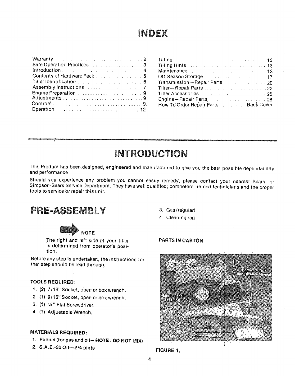
PRE...A.SSEMBLY
_ NOlrE
The right and left side of your tiller
is determined from operator's posi-
tion.
Before any step is undertaken, the instructions for
that step should be read through..
TOOLS REQUIRED:
to (2) 7116" Socket, open or bOx Wrench,
2. (1) 9116" Socket, open or box wrench..
3. (1) V4" Flat Screwdriver,
4. (t) AdjustableWrenoh,
MATERIALS REQUIRED:
1. Funnel (for-gas and olt,-_ NOTE: DO NOT MIX)
2. S..A_E.,-30 OtI_2% pints
3. Gas (regular)
4. Cleaning rag
PARTS IN CARTON
FIGURE !,
4
©
K
G j
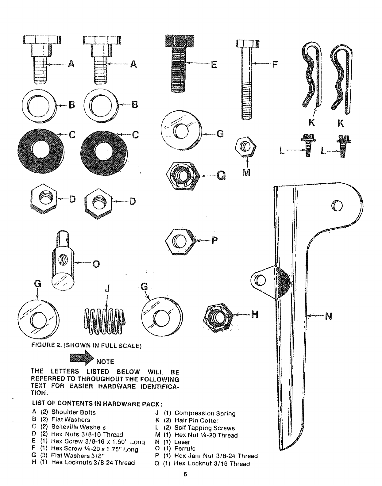
FIGURE 24{SHOWN IN FULL SCALE)
_NOTE
THE LETTERS LISTED BELOW
REFERRED TO THROUGHOUT THE FOLLOWING
TEXT FOR EASIER HARDWARE IDENTIFtCA-
TION,
LiST OF CONTENTS IN HARDWARE PACK :
A (2) Shoulder Bolts J (!) Compression Spring
B (2) Fiat Washers K (2) Hair Pin Cotter
C (2) Bellevilte Washe, s L (2) Self Tapping Sorews
P (2) Hex Nuts 3/8-16 Thread M (t) Hex Nut 1/4-20Thread
E (!) Hex Screw 3f8_t6 x 1..50" Lo_g N (1) Lever
F (1) HexScrewl/4.20xl.75"Long O (1) Ferrule
G (3) Flat Washers 31B" P (1) Hex ,Jam Nut 318-24 Thread
H (1) Hex Locknuts3t8-24Thread Q (1) Hex Locknut 3/16 Thread
Gk
WILt, BE
H
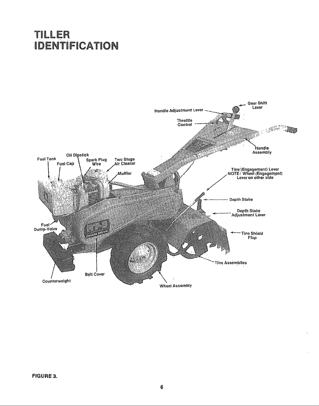
TBLLER
mDENTi:F6CAT ON
GearShill
Lover
Fuel Tank
.=-
Dum
Counterweight
011Di
Fuel Cap
Spsrk Plug
Wire
B_|t Cover
, " ,die
Assembly
Tine:(,Enga_er_e.nt) Lever
i NQTE: Wheel (Engagempn_)
Lever on other sld_
*'_........... Depth Stake
Depth Stake
.... Adjustment Lever
Tine Shield
Flap
FIGURE 3,
S
ASSEMBLY
INSTRUCTIONS
1. Handle Assembly
A. Place the handle assembty tn position on
the tiller so that tile holes in Ilandle line up
with holes in nqounting bracket..
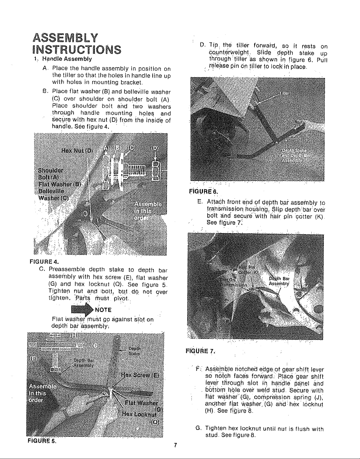
B. Place flat washer (B) and belleviIte washer
(C) over shoulder on shou!der bolt (A)
Place sl]oufder bolt ai_d two Washers
thro, ugh handle mounting hot.es and
s'eq.Ure wH.h he× nut (D) from ihe inside of
handle. See !!guPe 4. :
Dr "l!p. the tilte'r fOrwa?d, so it rests on
_o.unter_ejghl, $Iide d.ePth stake up
thrpughUl}er as s.ho,wn in, .figure 6, Pdll
rele&se #in On tiJier to loc_4 in place.
,+FJOURE6,
E. At.ta_.h ,front epd of d@pt.h bai" .assembly !o
tr_ni_mlssion hodsiag: Slip depth:bar:over
bolt _,nd secu_te w.fth hair ptn :9otter (K).
See l.0.re,7:
FIGURE 4.
C. Preassemble depth stake .to depth bar
assembly with hex sdrew (E), flat washer
(G) and hex locknut (Q)o See figure 5.
T_gl_tep nut an.d :boU, b_J.t d0. net over
tlOhtem ':P_,i.hsmu_t 'pivOt.
Flat W_Sh.er must go against s!:qt on
depth bai" assembly,
" 'I_::Ass..i_mB.ler_0tched edge:of gear shi-.ft lever
so n0(o.h faces forwa[d._:: P.!ac6gear shift
ie.vej" tl_rough slot th handle #An.el a.nd
66{t0._ h0.,leove_"we!d s{bd,-Secure:Wiih
: t=l_t w_,ller'(G)., oompre_s!e n .Sp(iog (J)i
andt.her fiat washer,(G) ahd: hex IOckhui
(H). See f!Ljbre'8.
G, Tighten hex tocknut until nut is Mush with
stud. See figure 8.
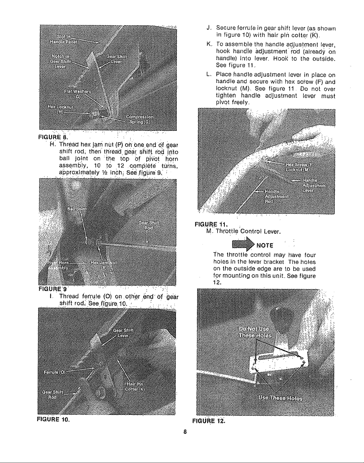
J_
Secure ferrule in gear shift lever (as shown
in figure 10) with hair p_n cotter (_),
K,
To assemble the handle adjustment lever,
hook handle ad]ustmen.t' t:od '(already on
handle) into lever, Hoot_ to the outside.
See figure 11,.
L.
Place handle adjustment tevet in place on
handle and secure with he× sci'ew (F) and
f0cl{nut (M), See figure 1t. Do not over
ttgilten handle adjustment lever must
pivot freely,
F GU.REi1.
M., ThrOttl e Control [.ever,
]_he throttle control may have four
holes in the lever bracket The holes
on the outside edge are to be used
for mounting on this unit., See figure
12.
NOTE -,
FIGURE 10.
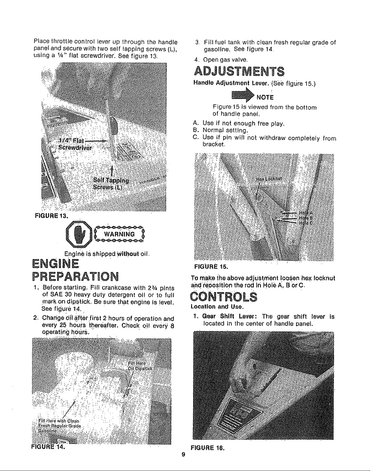
Placethrottle controlleverup throughthehandle
panelandsecurewith twoself tappingscrews(L),
usinga t/4" flat screwdriver: See figure !3
3 Fill fuel tank with c_ean fresh regular grade of
gasoline, see figure 14
4 Open gas valve.
ADJUSTNgNTS
Handle Adjustment Lever. (See figure 15.)
NOTE
Figure 15 is viewed from the bottom
of handle panet.
A. Use if not enough free play;
B. Normal setting.
C. Use _f pin wi{t not withdraw c0mpletely from
bracl<et_ *
FIGURE 13,
Engine tsshipped Wi{bout oil,
ENGINE
PREPARATION
1, Before starting. Fill crankcase with 23/4 pints
of SAE 30 heavy duty detergent oit or to full
mark on dipstick, Be sure that engine is !evet,
See figure 14, ..
2. Change 0(l._ter first 2 hours of operation and
every 25 hours the.re_ter, CheGk 0)_ eve_ 8
operati.ng h0grs, _ •
FIGURE .15.
To make the above adjustment !o0sen hex io_knut
a_nd'_e_os|!iOn the rod Ifi Hole A, B Or C,
CONTROLS
Location and Use.
1. Gear Shilt Lever: The gear shift lever is
located in the center of handle panel,
FIG
FIGURE 16.
9
A. Forward (1 thru 5)--. Move the lever t.o the
left and forward for each gear, See figure
16,
_NOTE
The engine must be running tO move
the gear shift lever, ".....
B_
Use (1) first and (2) second gears when
breaking the sod for the first time_
Use (3) third and (4! f0,urth gears when
till!ng soil which has been tilled before_
D.
Use (5) fifth gear for pulverizing solt or for
transporting the tiller,
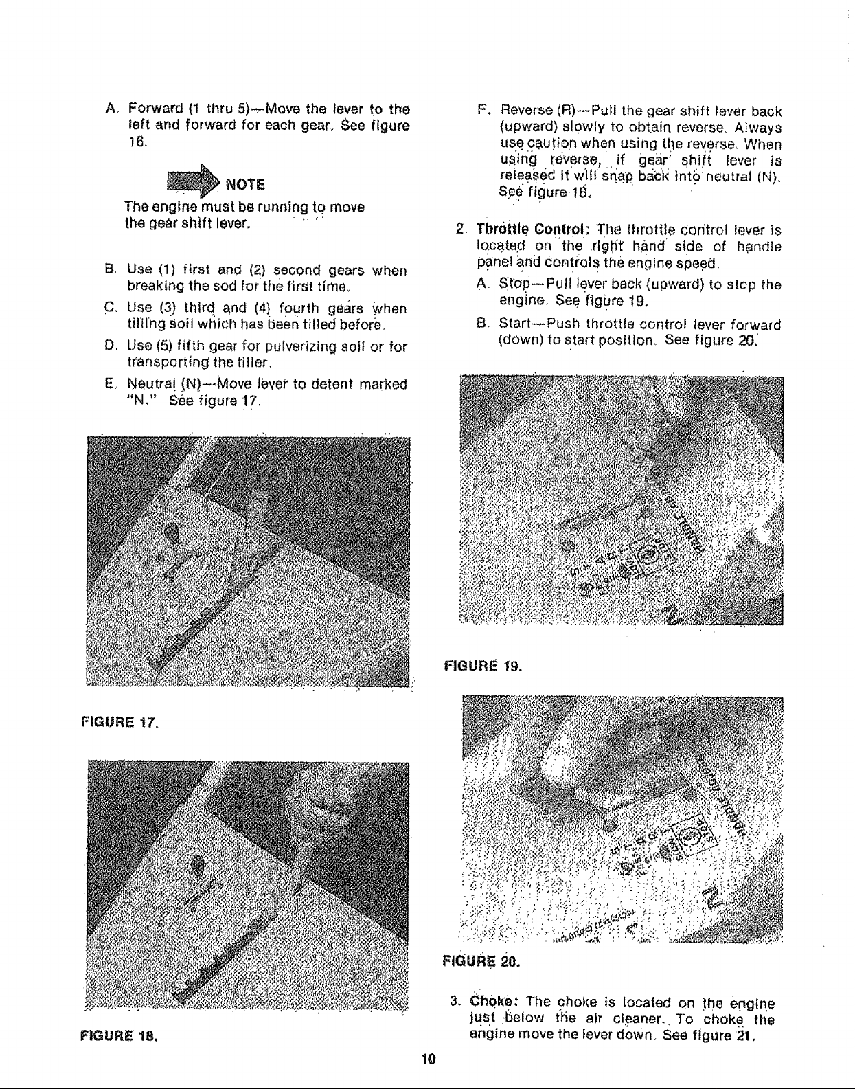
E
Neutra! ,(N)_Move lever to detent marked
"N," See figure 17.
F, Reverse (R) ....Pull the gear shift lever back
(upward) slowly to obtain, reverse, Always
use caution when using the reverse_ When
u_tng {:everSe, .if gear' shift lever is
re}eased It'w[tl sqap. ba_k int_: neutral (N),
Se_'figure 18,
2 Throttle Control: The throttle con'trol iever is
IQcated on the right' h_nd side of handle
panel arid _ontrels the engine speed,
A. St_op--Pull lever back (upWard) to stop the
engine, See fig0re 19,
B, Start_Push throttle oontrol lever forward
(down) to start position.. See figure 20,
FIGURE t7,
FIGURE 18.
FIGURE 19.
3. Ch0ke: The choke is located on the e.ng{qe
Jus.t .l_elow t'tle air cleaner. To choke the
engine move the lever down, See figure '21,
10