

Craftsman 247298770 Owner’s Manual
Sears
maliiual
f
CAUT :
Read SAFETY
RULESand
iNSTRUCTIONS
carefully
8F__._RS, P, DEBU6-_ AND 03., Cht_I1. 60684 U_.A.
and S_NS-SEARS LI_MYI2!D, Toronto, Canada
i m , i,,,i,ii ...................................... ,,,,.,,?,
PART NO, 770_7763
_RRFTSN_N_
. CHAJ
Ti E
o Assembly
o Operating
®Maintenance
. Repair Parts
IVE
TILLE
........ IIIl/l'
PRINTED IN U,S,A,,

FULL ONE YEAR WARRANTY !
For one year from the date of purchase, Sears will repai_ any defect in material or
workmanship in this TILLER at no charge
If the TtLLER is used for commercial or rental purposes, this warranty applies for onry
thirty days from the date of purchase.
Warranty service is available by contacting the nearest Sears store or Service Center
throughout the United States..
This warranty gives you specific Jegai rights, and you may afso have other rights
which vary from state to state..
Sears, Roebuck and Coo
Sears Tower
BSC 41-3
Chicago, IL 60684
DODOg D Da 0 _J_ Q9_0_0 QD 0 D_ 000001_ D_ 000 QO 0000____90 na _oDa@ ooooooo D_ _
2

IMPORTANT
__is suggested that this manual be read in its entirety before attempting to assemble or operate Keep this
manual in a safe place for future reference and for ordering replacemen! parts
This unit is shipped WITHOUT GASOLINE orO1L After assembly, see operaiing section of this manual
for proper fuel and amount,.
Your tiller is a precision piece of power equipment, not a l::lay thing Therefore exercise extreme caution at
al! times
SAFE OPERATION PRACTICES FOR TILLERS
11,
't. Read the Operating and Service Owner's
Manual carefully, Be thoroughly familiar with
the controls and the proper use of the equip-
ment..
2. Never allow children to operate a power tiller°
Only persons welt acquainted with these rules
of safe operation should be allowed to use
your tiller
Do not fill gasoline tank while engine is
running. Spilling gasoline on hot engine may
cause a fire or explosion,
12.
Do not run the engine while indoors, Exhaust
gases are deadly poisonous.
1;3.
Be careful not to touch the muffler after the
engine has been running, it is hot.
3 Keep the area of operation clear of a]f
persons, particularly small children and pets.
4. Do not operate equipment when barefoot or
wearing open sandals Always wear substan-
tial footwear.
5. Do not wear loose fitting clothing that could
get caught on the tillen
6. Do not start the engine unless the shift tever
is in the neutral (N) position.
7. Do not stand in front of the tiller while
starting the engine.
8. Do not place feet and hands on or near the
tines when starting the engine or while the
engine is running.
9. Do not leave the tiller unattended with the
engine running,,
t0. Do not walk in front of the tiller while the
engine ts running.
14,
Before any maintenance work is performed or
adjustments are made, remove the spark plug
wire and ground it on the engine block for
added safety.
15l&Use caution when tilling near buildings and
fences, rotating tines can cause damage or
injury.
Before attempting to remove rocks, bricks
and other objects from tines, stop the engine
and be sure the tines have stopped
completely. Disconnect t,he spark plug wire
and ground to prevent adctdental starting.
,
Check the tine and engine mounting bolts at
frequent intervals for proper tightness°
t8,
Keep all nuts, bolts and screws tight to be
sure the equipment is in safe working
condition
19.
Never store the equipment with gasoline in
the tank inside of a building where fumes may
reach an open flame or spark, Allow the
engine to coot before storing In any
enclosure°
UNDEX
Warranty .................................... 2
Safe Operation Practices ..................... 3
Introduction ................................... 4
Contents in Hardware Pack ......................... 5
Tiller Identification ................................ 6
Assembly Instructions ......................... 7
Adjustments ..................................... 9
Con trots ....................................... t 0
Engine Preparation ............................... 13
Operation ........................................ 13
Tilling .......................................... 14
Tilling Hints ..................................... 15
Maintenance ................................. 15
Off-Season Storage ............................ ! 9
Transmission--Repair Parts .................. 20
Tiller-- Repair Parts ................................ 22
Parts Information ..................... Back Cover
INTRODUCTION
This Product has been designed, engineered and manufactured to give you the best possible dependability
and performance.
Should you experience any problem you cannot easily remedy, please contact your nearest Sears, or
Simpson-Sears Service Department. They have well qualified, competent trained technicians and the proper
tools to service or repair this unit.
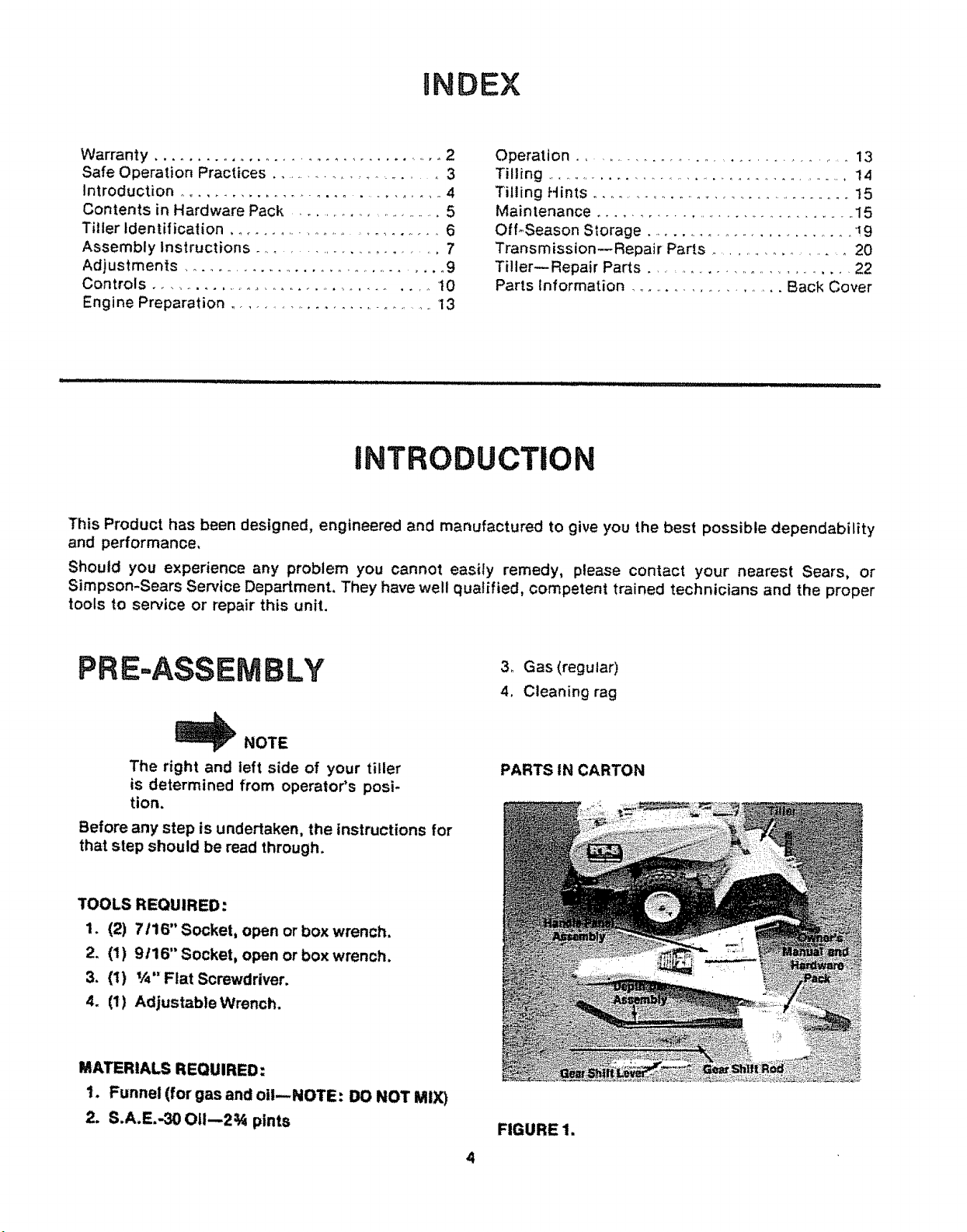
PRE-ASSEMBLY
_NOTE
The right and teft side of your tiller
is determined from operator's posi-
tion.
Before any step is undertaken, the instructions for
that step should be read through.
TOOLS REQUIRED:
1. (2) 7116" Socket, open or box wrench.
2. (1) 9t16" Socket, open or box wrench.
3, (1) V_" Flat Screwdriver.
4. (1) Adjustable Wrench.
MATERIALS REQUIRED:
1. Funnel (for gas and oil--NOTE: DO NOT MIX)
2. S.AoE.-30 O11--2¾ pints
3o Gas (regular)
4. Cleaning rag
PARTS IN CARTON
FIGURE 1.
4
C
E
F
G
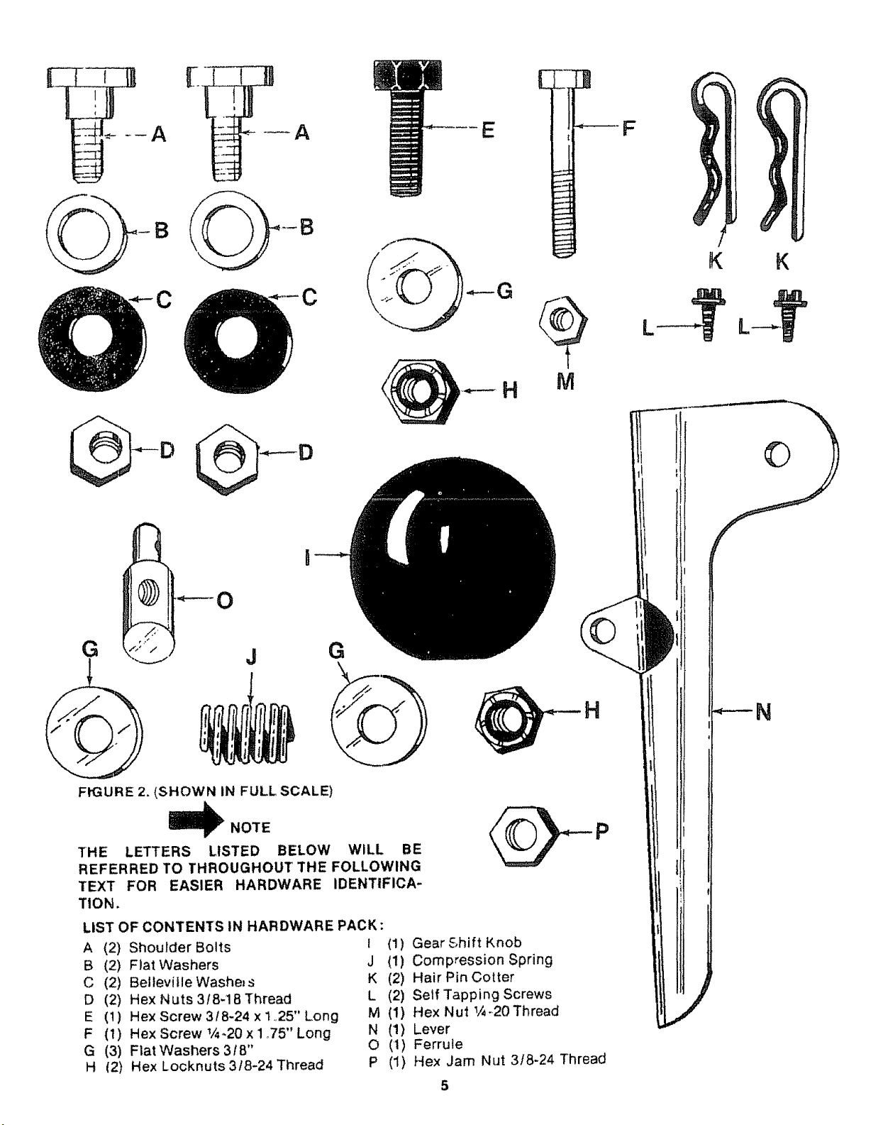
FIGURE 2, (SHOWN IN FULL SCALE)
THE LETTERS LISTED BELOW WILL BE
REFERRED TO THROUGHOUT THE FOLLOWING
TEXT FOR EASIER HARDWARE IDENTiFICA-
TION,
LIST OF CONTENTS IN HARDWARE PACK:
A (2) Shoulder Bolts
B (2) Flat Washers
C (2) BeltevitleWashe_s
D (2) Hex Nuts 318-18 Thread
E (t) Hex Screw 318-24 xi.,25" Long
F (t) Hex Screw !/4,20 x 1 ,,75" Long
G (3) Flat Washers 318"
H (2) Hex Locknuts 3/8-24 Thread
J
NOTE
G
I (1) Gear Shift Knob
J (1) Compression Spring
K (2) Hair Pin Cotter
L (2) Serf Tapping Screws
M (1) Hex Nut _-.20Thread
N (1) Lever
O (1) Ferruie
P
(1) Hex Jam Nut 3f8-24 Thread
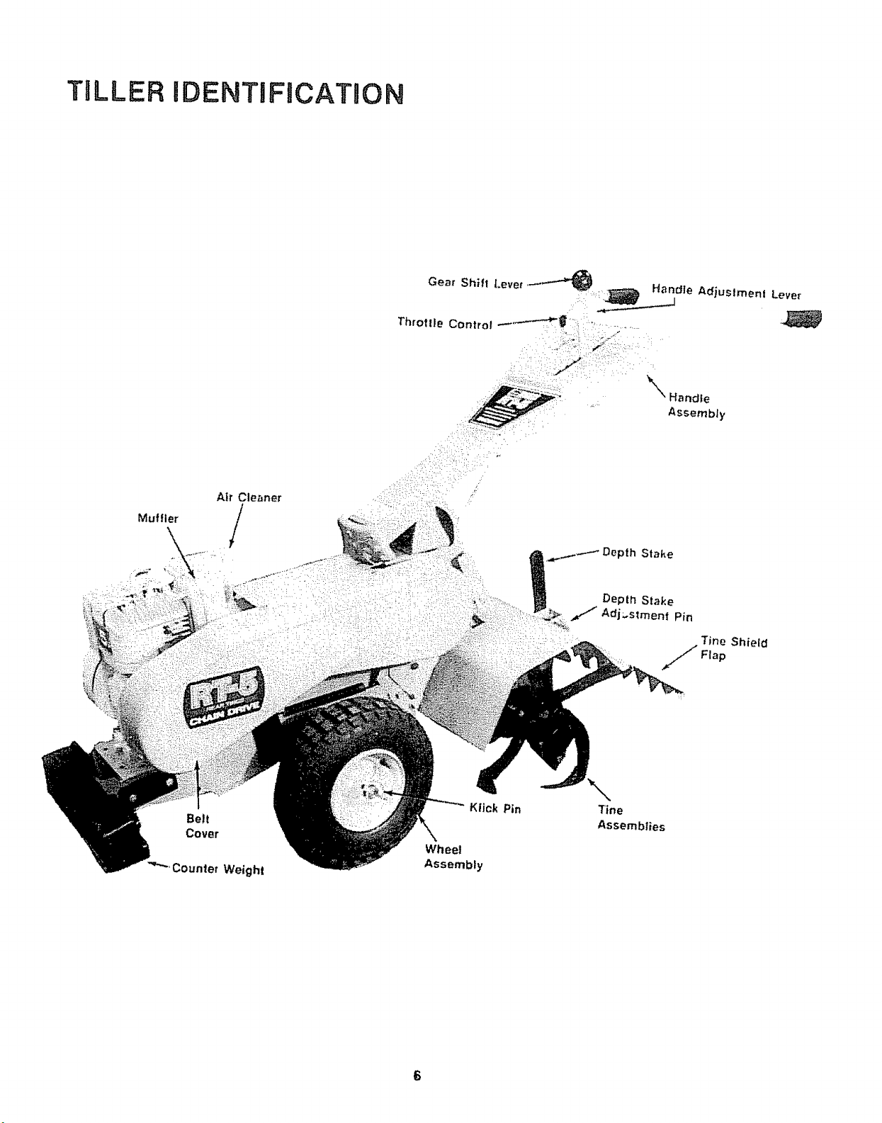
TILLER IDENTIFICATION
Belt
Cover
3ounter Weight
Klick Pin
Depth Slake
Adj..stmen{ Pin
Shield
Tine
Assemblies
6
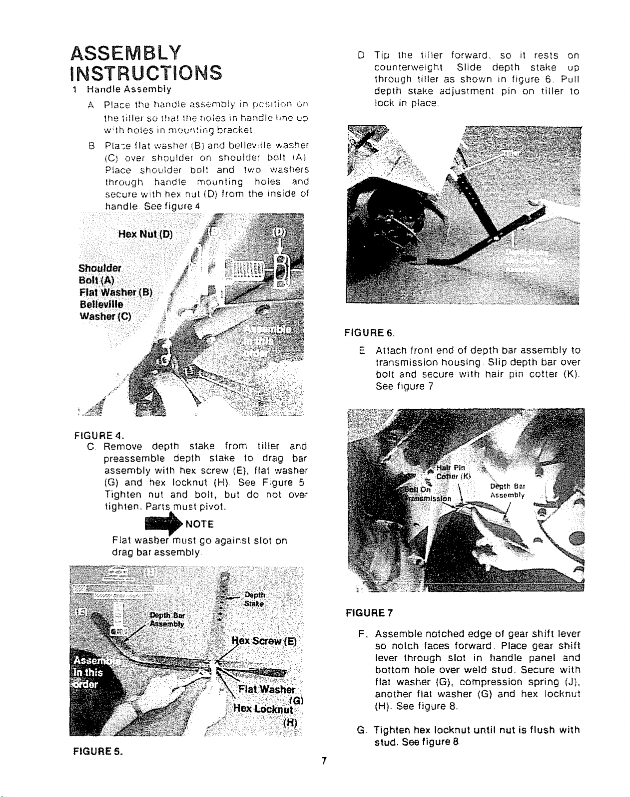
ASSEMBLY
INSTRUCTIONS
1 Handle Assembly
A Place the handle assembly in p,:;s,'",k)n Or:
the tiller so that the holes in handle Ime up
w_th holes in mountir, g bracket
g Place flat washer (B} and bellevi_le washer
(C) over shoulder on shoulder bolt (A)
Place shou}der bolt and two washers
through handle mounting holes and
secure with lie× nut (D) from the inside of
handle. See figure 4
D
Tip the tiller forward, so it rests on
counterweight Slide depth stake up
through titler as shown in figure 6, Pull
depth stake adjustment pin on tiller to
lock in place
FIGURE 6,
FIGURE 4.
C Remove depth stake from tiller and
preassemble depth stake to drag bar
assembly with hex screw (E), flat washer
(G) and hex Iocknut (H). See Figure 5
Tighten nut and bolt, but do not over
tightem Parts must pivot.
NOTE
Flat washer must go against slot on
drag bar assembly
E
Attach front end of depth bar assembly to
transmission housing Slip depth bar over
bolt and secure with hair pin cotter (K).
See figure 7
FIGURE 7
F_
Assemble notched edge of gear shift lever
so notch faces forward. Place gear shift
lever through slot in handle panel and
bottom hole over weld stud_ Secure with
flat washer (G), compression spring (J),
another flat washer (G) and hex locknut
(H)° See figure 8,
@
FIGURE 5.
G. Tighten hex Iocknut until nut is flush with
stud. See figure 8
7
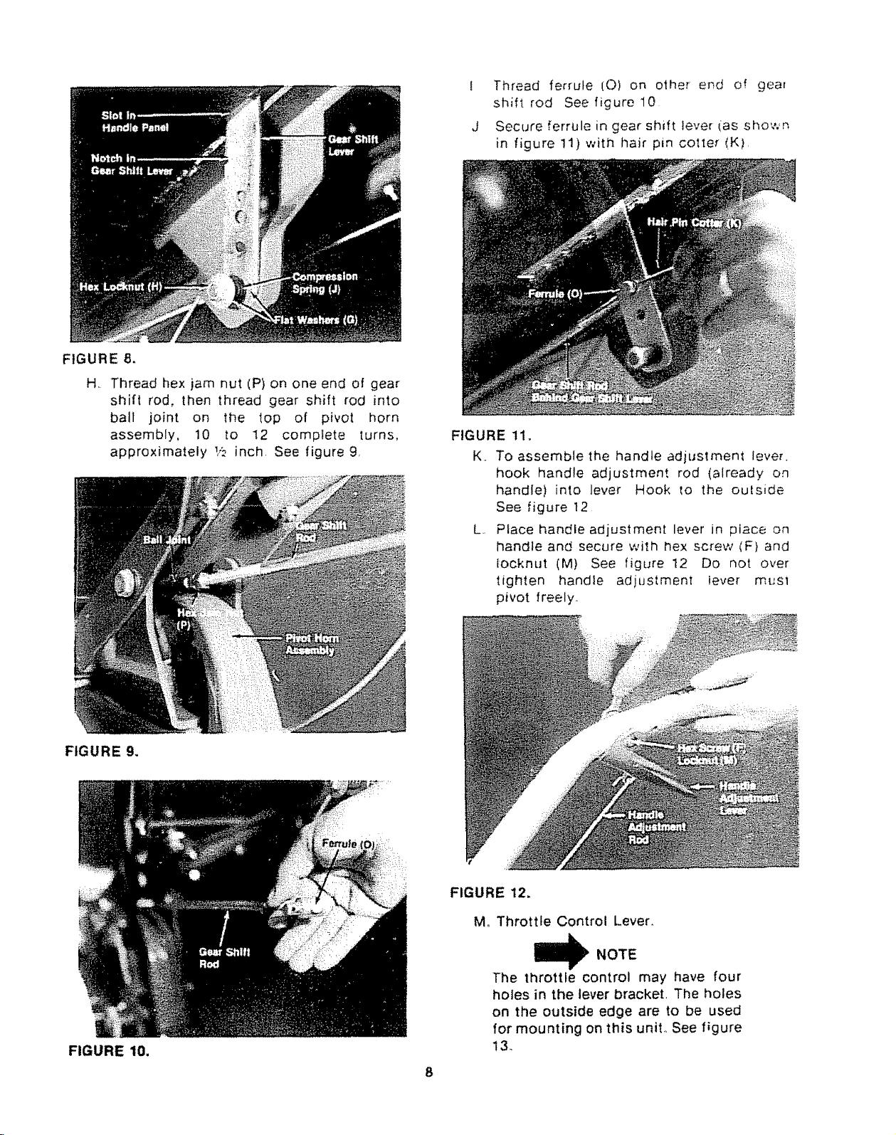
FIGURE 8.
H. Thread hex jam nut (P) on one end of gear
shift rod, then thread gear shift rod into
ball joint on the top of pivot horn
assembly, 10 to 12 complete turns,
approximately 1,,t,inch. See figure 9,
Thread ferrule [0) on other er_.d of gear
shift rod See figure 10
Secure ferrule in gear shift lever (as shown
in figure 11) with llair pin cotter (K),
FIGURE 11.
K,,
To assemble the handle adjustment lever.
hook handle adjustment rod (already on
handle) into lever Hook to the outside
See figure 12
L,,
Place handle adjustment lever in place on
handle and secure with hex screw (F) and
tocknut (M) See figure 12 Do not over
tighten handle adjustment iever mt'sl
pivot freely.
FIGURE 9.
FIGURE 10.
FIGURE 12.
M. Throttle Control Lever_
NOTE
The throttle control may have four
holes in the lever bracket, The holes
on the outside edge are to be used
for mounting on this unit° See figure
!3.
8
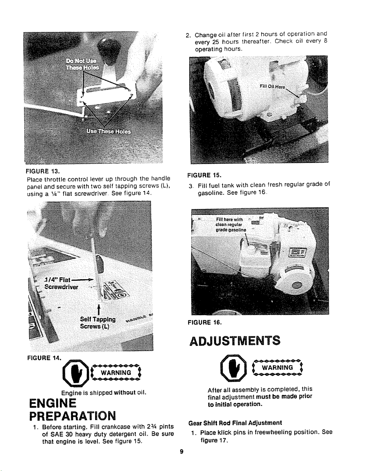
FIGURE 13.
Place throttle control lever up through the handle
panel and secure with two self tapping screws (L),
using a 1/4" fiat screwdriver.. See figure 14_
2, Change oil after first 2 hours of operation and
every 25 hours thereafter_ Check oil every 8
operating hours.
FIGURE 15.
3- Fill fuel tank with clean fresh regular grade of
gasoline. See figure 16..
FIGURE 14.
Engine is shipped without oil,
ENGINE
PREPARATION
1o Before starting, Fill crankcase with 2_A pints
of SAE 30 heavy duty detergent oil, Be sure
that engine is level, See figure 15,
FIGURE 16.
ADJUSTMENTS
After all assembly is completed, this
final adjustment must be made prior
to initial operation.
Gear Shift Rod Final Adjustment
1. Place ktick pins in freewheeling position. See
figure 17,
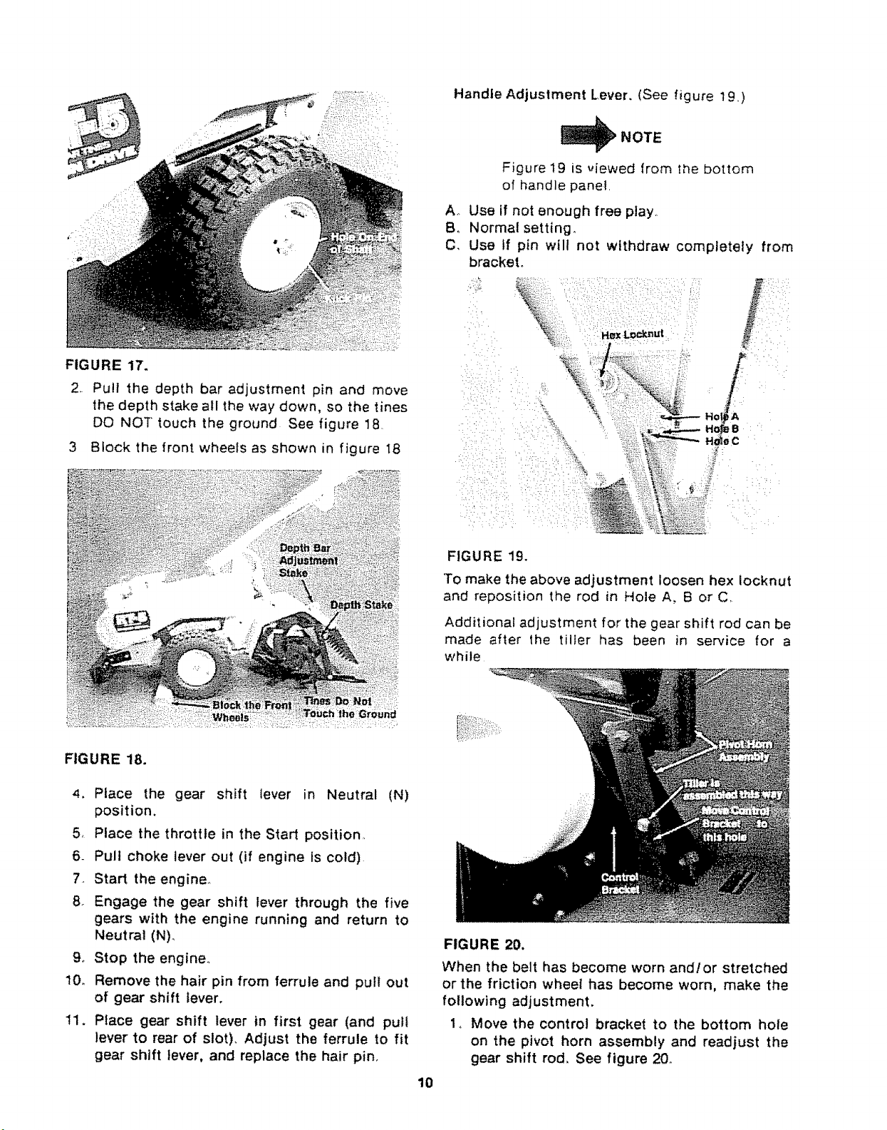
FIGURE 17.
2 Pull the depth bar adjustment pin and move
the depth stake all the way down. so the tines
DO NOT" touch the ground See figure 18
3 Block the front wheels as shown in figure 18
Handle Adjustment Lever. (See figure t9 )
NOTE
Figure 19 is _,iewed from the bottom
of handle panel
A_ Use if not enough free play
B. Normal setting°
C, Use If pin wilt not withdraw completely from
bracket.
FIGURE 18.
4. Place the gear shift lever in Neutral (N)
position.
5, Place the throttle in the Start position
6. Pull choke lever out (if engine Is cold)
7. Start the engine_
8 Engage the gear shift lever through the five
gears with the engine running and return to
Neutral (N)_
9. Stop the engine,
10o Remove the hair pin from ferrule and pull out
of gear shift lever,
11. Place gear shift lever in first gear (and pull
lever to rear of slot), Adjust the ferrule to fit
gear shift lever, and replace the hair pin,
FIGURE 19.
To make the above adjustment loosen hex iocknut
and reposition the rod in Hole A, B or C.
Additional adjustment for the gear shift rod can be
made after lhe tiller has been in service for a
while
FIGURE 20.
When the belt has become worn and/or stretched
or the friction wheel has become worn, make the
following adjustment.
1. Move the control bracket to the bottom hole
on the pivot horn assembly and readjust the
gear shift rod, See figure 20_
10
 Loading...