

Craftsman 247270200 Owner’s Manual

Owner's Manual
Riding Mower
Model No.
247.27020
CAUTION: Before
using this product,
read this manual and
follow all safety rules
and operating
instructions.
For answers to your questions about this product, call:
1-800-659-5917
Sears Craftsman Help Line
(5 am. - 5 pm., Mon. - Sat.)
• Safety
• Operation
• Maintenance
• Storage
• Espanbl
Sears, Roebuck And Co., Hoffman Estates, IL 60179 U.S.A.
Visit our website: www.sears.com/craftsman FORM NO. 769-00624
Printed in U.S.A. (1/2003)

Content Page
Warranty Information ................................ 2
Safe Operation Practices .......................... 3
Slope Gauge ............................................ 6
Assembly ................................................. 7
Operation ................................................. 9
Service & Adjustment ............................... 15
LIMITED WARRANTY ON RIDING MOWER: For two (2) years from the date of purchase, if this Craftsman Riding Equipment is
maintained, lubricated and tuned up according to the instructions in the owner's manual, Sears will repair or replace free of
charge any parts that are found 1obe defective in material or workmanship according to the guidelines of coverage listed below.
Sears will also provide free labor for these applicable warranted parts for the two full years. During first 30 days of purchase,
there will be no charges to service the product at your home for issues covered by this warranty. (See exclusions below).
For your convenience, IN HOME warranty service will still be available after the first 30 days of purchase, but a trip charge will
apply. This charge will be waived if the product is dropped off at an authorized Sears location. For the nearest authorized Sears
location, please call 1-800-4-MY-HOME®. This warranty applies only while this product is within the United States.
EXCLUSIONS
This Warranty does not cover:
Expendable items which become worn during normal use, including but not limited to blades, spark plugs, air cleaners,
belts, and oil filters.
Standard Maintenance Servicing, oil changes or tune-ups
Tire replacement or repair caused by punctures from outside objects, such as nails, thorns, stumps, or glass.
Repairs necessary because of operator abuse, including but not limited 1o,damage caused by towing objects beyond the
capability of the riding equipment, impacting objects that bend the frame or crankshaft, or over-speeding the engine.
Repairs necessary because of operator negligence, including but not limited to, electrical and mechanical damage caused
by improper storage, failure to use the proper grade and amount of engine oil, failure to keep the deck clear of flammable
debris, or failure to maintain the equipment according 1othe instructions contained in the owner's manual.
Engine (fuel system) cleaning or repairs caused by fuel determined to be contaminated or oxidized (stale). In general, fuel
should be used within 30 days of its purchase date.
Normal deterioration and wear of the exterior finishes, or product label replacement.
Riding equipment used for commercial or rental purposes.
LIMITED WARRANTY ON BATTERY
For ninety (90) days from date of purchase, if any battery included with this riding equipment proves defective in material or
workmanship and our testing determines the battery will not hold charge, Sears will replace the battery at no charge. During the
first 30 days of purchase, there will be no charges to replace the battery at your home. After the first 30 days, for your
convenience, IN-HOME warranty service will still be available but a trip charge will apply. This charge will be waived if the
Craftsman product is dropped of at an authorized Sears location. For the nearest authorized Sears location, please call 1-800-4-
MY-HOME®. This battery warranty applies only while this product is within the United States. This warranty gives you specific
legal rights, and you may also have other rights, which vary, from state to state.
Sears, Roebuck and Co.,Dept.817WA, Hoffman Estates, IL 60179
Content Page
Maintenance ............................................... 20
Off-Season Storage .................................... 23
Trouble-Shooting ........................................ 23
Parts List ..................................................... 25
Espan_)l ...................................................... 46
Customer Support ...................................... 72
Horsepower: ............................... 9.0
Engine Oil ................................... 36 oz. or 1.1 liters
Fuel ............................................ Unleaded Regular
Spark Plug: ................................. P/N 802592
Engine: ........................................ 198707-0141
Ignition Key (Std.) ........................ P/N 725-0201
Model Number ........................... 247.27020
Serial Number ...........................................................
Date of Purchase ......................................................
Record both serial number and date of purchase and keep
in a safe place for future reference.
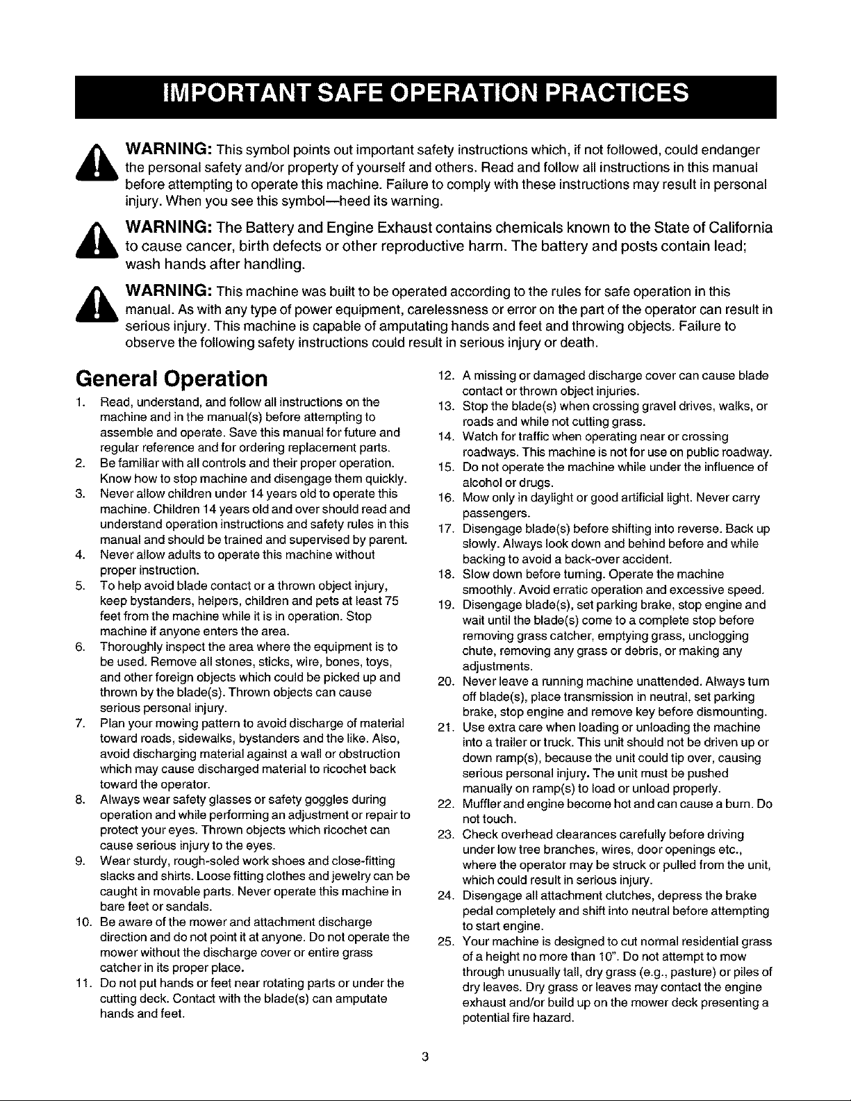
WARNING: This symbol points out important safety instructions which, if not followed, could endanger
the personal safety and/or property of yourself and others. Read and follow all instructions in this manual
before attempting to operate this machine. Failure to comply with these instructionsmay result in personal
injury. When you see this symbol--heed its warning.
WARNING: The Battery and Engine Exhaust contains chemicals known to the State of California
to cause cancer, birth defects or other reproductive harm. The battery and posts contain lead;
wash hands after handling.
WARNING: This machine was built to be operated according to the rules for safe operation in this
manual. As with any type of power equipment, carelessness or error on the part of the operator can result in
serious injury. This machine is capable of amputating hands and feet and throwing objects. Failure to
observe the following safety instructions could result in serious injury or death.
General Operation
1. Read, understand, and follow all instructions on the
machine and in the manual(s) before attempting to
assemble and operate. Save this manual for future and
regular reference and for ordering replacement parts.
2. Be familiar with all controls and their proper operation.
Know how to stop machine and disengage them quickly.
3. Never allow children under 14 years old to operate this
machine. Children 14 years old and over should read and
understand operation instructions and safety rules inthis
manual and should be trained and supervised by parent.
4. Never allow adults to operate this machine without
proper instruction.
5. To help avoid blade contact or a thrown object injury,
keep bystanders, helpers, children and pets at least 75
feet from the machine while it is in operation. Stop
machine if anyone enters the area.
6. Thoroughly inspect the area where the equipment is to
be used. Remove all stones, sticks, wire, bones, toys,
and other foreign objects which could be picked up and
thrown by the blade(s). Thrown objects can cause
serious personal injury.
7. Plan your mowing pattern to avoid discharge of material
toward roads, sidewalks, bystanders and the like. Also,
avoid discharging material against a wall or obstruction
which may cause discharged material to ricochet back
toward the operator.
8. Always wear safety glasses or safety goggles during
operation and while performing an adjustment or repair to
protect your eyes. Thrown objects which ricochet can
cause serious injury to the eyes.
9. Wear sturdy, rough-soled work shoes and close-fitting
slacks and shirts. Loose fitting clothes and jewelry can be
caught in movable parts. Never operate this machine in
bare feet or sandals.
10. Be aware of the mower and attachment discharge
direction and do not point it at anyone. Do not operate the
mower without the discharge cover or entire grass
catcher in its proper place.
11. Do not put hands or feet near rotating parts or under the
cutting deck. Contact with the blade(s) can amputate
hands and feet.
12. A missing or damaged discharge cover can cause blade
contact or thrown object injuries.
13. Stop the blade(s) when crossing gravel drives, walks, or
roads and while not cutting grass.
14. Watch for traffic when operating near or crossing
roadways. This machine is not for use on public roadway.
15. Do not operate the machine while under the influence of
alcohol or drugs.
16. Mow only in daylight or good artificial light. Never carry
passengers.
17. Disengage blade(s) before shifting into reverse. Back up
slowly. Always look down and behind before and while
backing to avoid a back-over accident.
18. Slow down before turning. Operate the machine
smoothly. Avoid erratic operation and excessive speed.
19. Disengage blade(s), set parking brake, stop engine and
wait until the blade(s) come to a complete stop before
removing grass catcher, emptying grass, unclogging
chute, removing any grass or debris, or making any
adjustments.
20. Never leave a running machine unattended. Always turn
off blade(s), place transmission in neutral, set parking
brake, stop engine and remove key before dismounting.
21. Use extra care when loading or unloading the machine
into a trailer or truck. This unit should not be driven up or
down ramp(s), because the unit could tip over, causing
serious personal injury. The unit must be pushed
manually on ramp(s) to load or unload properly.
22. Mufflerandenginebecomehotandcancauseabum. Do
not touch.
23. Check overhead clearances carefully before driving
under low tree branches, wires, door openings etc.,
where the operator may be struck or pulled from the unit,
which could result in serious injury.
24. Disengage all attachment clutches, depress the brake
pedal completely and shift into neutral before attempting
to start engine.
25. Your machine is designed to cut normal residential grass
of a height no more than 10". Do not attempt to mow
through unusually tall, dry grass (e.g., pasture) or piles of
dry leaves. Dry grass or leaves may contact the engine
exhaust and/or build up on the mower deck presenting a
potential fire hazard.
26.Useonlyaccessoriesandattachmentsapprovedforthis
machinebythemachinemanufacturer.Read,
understandandfollowallinstructionsprovidedwiththe
accessoryorattachment.
27.Dataindicatesthatoperators,age60yearsandabove,
areinvolvedinalargepercentageoftractor-related
injuries.Theseoperatorsshouldevaluatetheirabilityto
operatethetractorsafelyenoughtoprotectthemselves
andothersfromseriousinjury.
28.Ifsituationsoccurwhicharenotcoveredinthismanual,
usecareandgoodjudgment.ContactSearsservice
centerforassistance.
Slope Operation
Slopes are a major factor related to loss of control and tip-
over accidents which can result in severe injury or death. All
slopes require extra caution. If you cannot back up the slope
or if you feel uneasy, do not mow it.
For safety, use the slope gauge included as part of this
manual to measure slopes before operating this unit on a
sloped or hilly area. If the slope is greater than 15 degrees as
shown on the slope gauge, do not operate this unit there.
Do:
1. Mow up and down slopes, not across. Exercise extreme
caution when changing direction on slopes.
2. Watch for holes, ruts, bumps, rocks, or other hidden
objects. Uneven terrain could overturn the machine. Tall
grass can hide obstacles.
3. Use slow speed. Choose a low enough speed setting so
that you will not have to stop or shift while on the slope.
Tires may lose traction on slopes even though the brakes
are functioning properly. Always keep machine in gear
when going down slopes to take advantage of engine
braking action.
4. Follow the manufacturer's recommendations for wheel
weights or counterweights to improve stability of the
machine. Use extra care with grass catchers or other
attachments. These can change stability of the machine.
5. Keep all movement on the slopes slow and gradual. Do
not make sudden changes in speed or direction. Rapid
engagement or braking could cause the front of the
machine to lift and rapidly flip over backwards which
could cause serious injury.
6. Avoid starting or stopping on a slope. If tires lose traction,
disengage the blade(s) and proceed slowly straight down
the slope.
Do Not:
1. Do not turn on slopes unless necessary; then, turn slowly
and gradually downhill, if possible.
2. Do not mow near drop-off sites, ditches or embankments.
The mower could suddenly turn over ifa wheel is over the
edge of a cliff, ditch, or if an edge caves in.
3. Do not try to stabilize the machine by putting your foot on
the ground.
4. Do not use a grass catcher on steep slopes.
5. Do not mow on wet grass. Reduced traction could cause
sliding.
6. Do not shift to neutral and coast downhill. Over-speeding
may cause theoperator to lose control of the machine
resulting in serious injury or death.
7.
Do not tow heavy pull behind attachments (e.g. loaded
dump cart, lawn roller, etc.) on slopes greater than 5
degrees. When going down hill, the extra weight tends to
push the tractor and may cause you to loose control. (e.g.
tractor may speed up, braking and steering ability are
reduced, attachment may jack-knife and cause tractor to
overturn).
Children
1. Tragic accidents can occur ifthe operator is not alert to
the presence of children. Children are often attracted to
the machine and the mowing activity. They do not
understand the dangers. Never assume that children will
remain where you last saw them.
a. Keep children out of the mowing area and in
watchful care of a responsible adult other than the
operator.
b. Be alert and turn machine off if a child enters the
area.
c. Before and while backing, look behind and down
for small children.
d. Never carry children, even with the blade(s) shut
off. They may fail off and be seriously injured or
interfere with safe machine operation.
e. Use extreme care when approaching blind
corners, doorways, shrubs, trees or other objects
that may block your vision of a child who may run
into the machine.
f. Disengage the cutting blade(s) before shifting in
reverse. The "No-Cut-In Reverse" feature
emphasizes not to cut in reverse and to avoid
back-over accidents; do not defeat it.
g. Keep children away from hot or running engines.
They can suffer burns from a hot muffler.
h. Remove key when machine is unattended to
prevent unauthorized operation.
2. Never allow children under 14 years old to operate the
machine. Children 14 years old and over should read and
understand the operation instructions and safety rules in
this manual and should be trained and supervised by a
parent.
Service
Safe Handling Of Gasoline
1. To avoid personal injury or property damage use extreme
care in handling gasoline. Gasoline is extremely
flammable and the vapors are explosive. Serious
personal injury can occur when gasoline is spilled on
yourself or your clothes which can ignite. Wash your skin
and change clothes immediately.
a. Use onlyan approved gasoline container.
b. Never fill containers inside a vehicle or on a truck
or trailer bed with a plastic liner. Always place
containers away from your vehicle before filling.
c. When practical, remove gas-powered equipment
from the truck ortrailer and refuel it on the ground.
Ifthis is not possible, then refuel such equipment
on a trailer with a portable container, rather than
from a gasoline dispenser nozzle.

d. Keepthenozzleincontactwiththerimofthefuel
tankorcontaineropeningatalltimesuntilfueling
iscomplete.DOnotuseanozzlelock-open
device.
e. Extinguishallcigarettes,cigars,pipesandother
sourcesofignition.
f. Neverfuelmachineindoors.
g. Neverremovegascaporaddfuelwhilethe
engineishotorrunning.Allowenginetocoolat
leasttwominutesbeforerefueling.
h. Neveroverfillfueltank.Filltanktonomorethan
Y_inchbelowbottomoffillernecktoallowspace
forfuelexpansion.
i. Replacegasolinecapandtightensecurely.
j. Ifgasolineisspilled,wipeitofftheengineand
equipment.Moveunittoanotherarea.Wait5
minutesbeforestartingtheengine.
k. Toreducefirehazards,keepmachinefreeof
grass,leaves,orotherdebrisbuild-up.Cleanup
oilorfuelspillageandremoveanyfuelsoaked
debris.
L Neverstorethemachineorfuelcontainerinside
wherethereisanopenflame,sparkorpilotlight
asonawaterheater,spaceheater,furnace,
clothesdryerorothergasappliances.
m. Allowamachinetocoolatleast5minutesbefore
storing.
General Service
1. Never run an engine indoors or in a poorly ventilated
area. Engine exhaust contains carbon monoxide, an
odorless, and deadly gas.
2. Before cleaning, repairing, or inspecting, make certain
the blade(s) and all moving parts have stopped.
Disconnect the spark plug wire and ground against the
engine to prevent unintended starting.
3. Periodically check to make sure the blades come to
complete stop within approximately (5) five seconds after
operating the blade disengagement control. If the blades
do not stop within the this time frame, your unit should be
serviced professionally by an authorized dealer.
4. Check brake operation frequently as it is subjected to
wear during normal operation. Adjust/service as required.
5. Check the blade(s) and engine mounting bolts at
frequent intervals for proper tightness. Also, visually
inspect blade(s) for damage (e.g., excessive wear, bent,
cracked).
Replace the blade(s) with the original equipment
manufacturer's (O.E.M.) blade(s) only, listed in this
manual. "Use of parts which do not meet the original
equipment specifications may lead to improper
performance and compromise safety!"
6. Mower blades are sharp. Wrap the blade or wear gloves,
and use extra caution when servicing them.
7. Keep all nuts, bolts, and screws tight to be sure the
equipment is in safe working condition.
8. Never tamper with the safety interlock system or other
safety devices. Check their proper operation regularly.
9. After striking a foreign object, stop the engine, disconnect
the spark plug wire(s) and ground against the engine.
Thoroughly inspect the machine for any damage. Repair
the damage before starting and operating.
10. Never attempt to make adjustments or repairs to the
machine while the engine is running.
11. Grass catcher components and the discharge cover are
subject to wear and damage which could expose moving
parts or allow objects to be thrown. For safety protection,
frequently check components and replace immediately
with original equipment manufacturer's (O.E.M.) parts
only, listed in this manual. "Use of parts which do not
meet the original equipment specifications may lead to
improper performance and compromise safety!"
12. Do not change the engine governor settings or over-
speed the engine. The governor controls the maximum
safe operating speed of the engine.
13. Maintain or replace safety and instruction labels, as
necessary.
14. Observe proper disposal laws and regulations for gas,
oil, etc. to protect the environment.
Your Responsibility
Restrict the useof this power machine to persons who
read, understand and follow the warnings and instructions
in this manual and on the machine.

SIGHT AND HOLD THIS LEVEL WITH A VERTICAL TREE
Z
t.O
,,,Z
WARNING
_ Do not mow on inclines with a slope in excess of 15 degrees (a rise of approximately 2-1/2 feet every 10 feet).
t_ _. A riding mower could overturn and cause serious injury. If operating a walk-behind mower on such a slope, it
_ is extremely difficult to maintain your footing and you could slip, resulting in serious injury.
w w Operate RIDING mowers up and down slopes, never across the face of slopes.
O Operate WALK-BEHIND mowers across the face of slopes, never up and down slopes.
Unpacking
1. Remove ait screws and staples from the crate.
2. Holding sides of the crate firmly, lift top of the crate
up and set it aside. Avoid tire punctures.
3. Remove and discard plastic bag covering the unit.
4. Lift the rear of the mower and clear the bottom of
the crate. Repeat for the front.
5. Be sure the parking brake isdisengaged. See
Figure 6 for location of the parking brake.
6. Roll unit out of the crate.
Vent
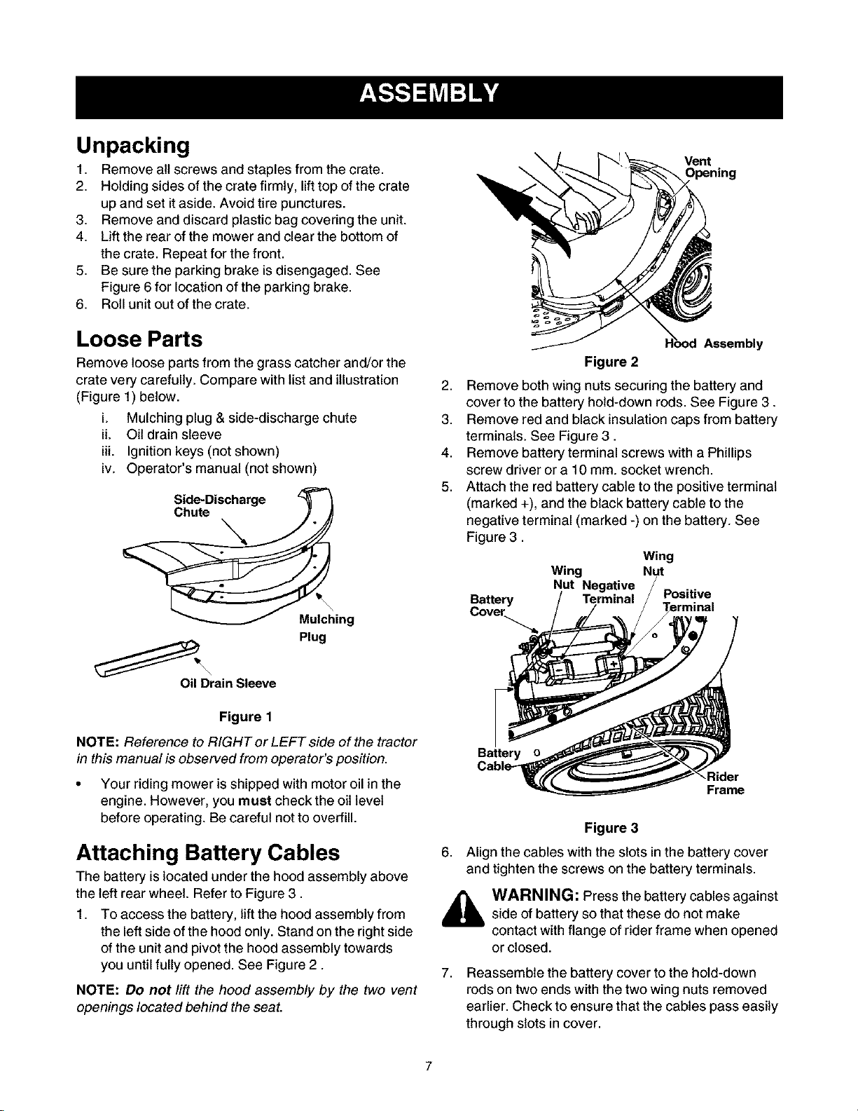
Loose Parts
Remove loose parts from the grass catcher and/or the
crate very carefully. Compare with list and illustration
(Figure 1) below.
i. Mulching plug & side-discharge chute
iL Oil drain sleeve
iii. Ignition keys (not shown)
iv. Operator's manual (not shown)
Side-Discharge z_
Mulching
plug
Oil Drain Sleeve
Figure 1
NOTE: Reference to RIGHT or LEFT side of the tractor
in this manual is observed from operator's position.
• Your riding mower is shipped with motor oil in the
engine. However, you must check the oil level
before operating. Be careful not to overfill.
Attaching Battery Cables
The battery is located under the hood assembly above
the left rear wheel. Refer to Figure 3.
1. To access the battery, lift the hood assembly from
the left side of the hood only. Stand on the right side
of the unit and pivot the hood assembly towards
you until fully opened. See Figure 2.
NOTE: Do not lift the hood assembly by the two vent
openings located behind the seat.
Assembly
Figure 2
2. Remove both wing nuts securing the battery and
cover to the battery hold-down rods. See Figure 3.
3. Remove red and black insulationcaps from battery
terminals. See Figure 3.
4. Remove battery terminal screws with a Phillips
screw driver or a 10 mm. socket wrench.
5. Attach the red battery cable to the positive terminal
(marked +), and the black battery cable to the
negative terminal (marked -) on the battery. See
Figure 3.
Wing
Wing Nut
Nut Negative
Battery
Cove_
Battery
6. Align the cables with the slots in the battery cover
and tighten the screws on the battery terminals.
Terminal Positive
Rider
Frame
Figure 3
WARNING: Press the battery cables against
side of battery so that these do not make
contact with flange of rider frame when opened
or closed.
7,
Reassemble the battery cover to the hold-down
rods on two ends with the two wing nuts removed
earlier. Check to ensure that the cables pass easily
through slots incover.
8. Placerighthandontheleftsideoftheseatand
slowlylowerthehoodassemblyuntitlfullyclosed.
NOTE:Do not place your hand around the bottom
edge of the hood assembly; it may get pinched between
the hood assembly and grass catcher or the frame rail.
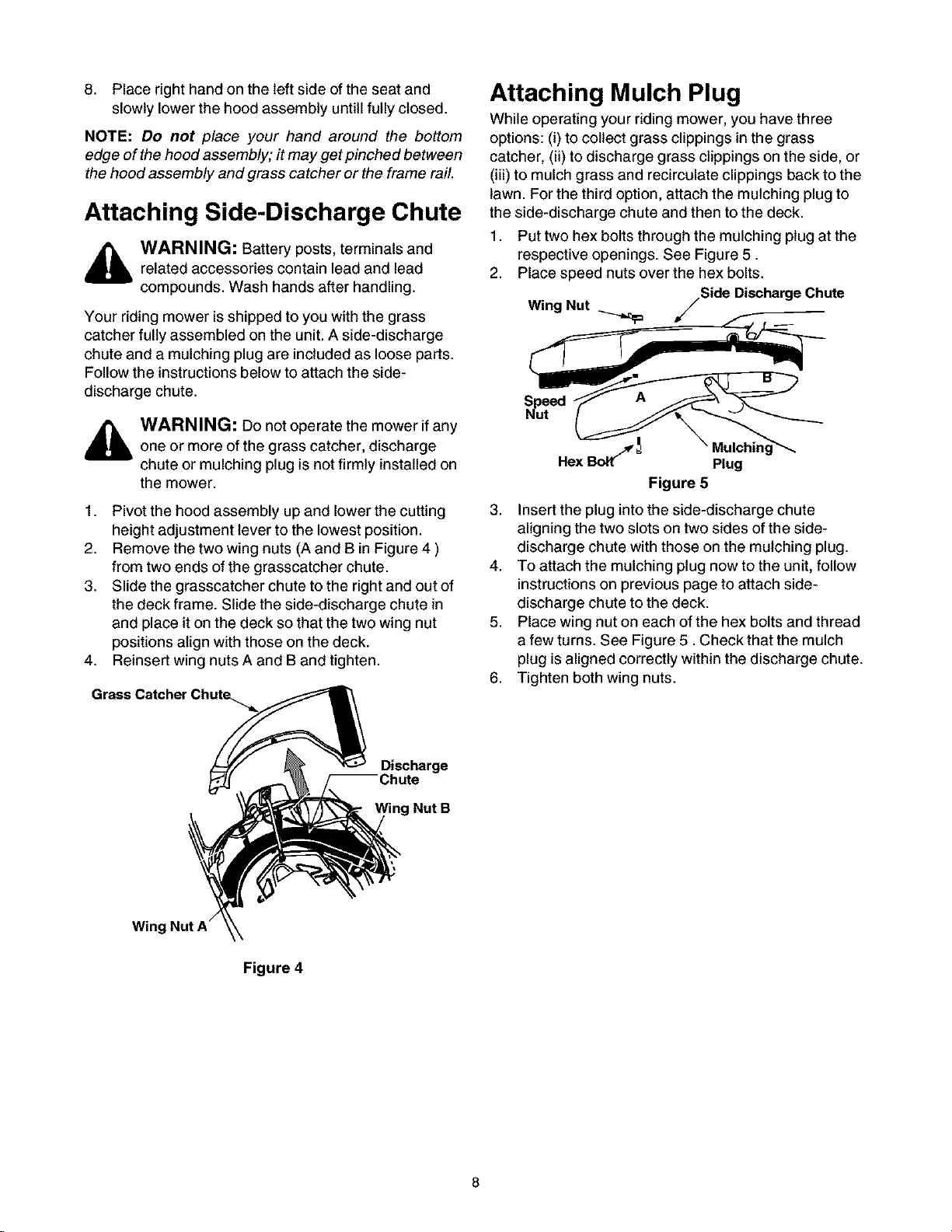
Attaching Side-Discharge Chute
_k WARNING: Battery posts, terminals and
Your riding mower is shipped to you with the grass
catcher fully assembled on the unit. A side-discharge
chute and a mulching plug are included as loose parts.
Follow the instructions below to attach the side-
discharge chute.
1. Pivot the hood assembly up and lower the cutting
2. Remove the two wing nuts (A and B in Figure 4 )
3. Slide the grasscatcher chute to the right and out of
4. Reinsert wing nuts A and B and tighten.
Grass Catcher Chute_
related accessories contain lead and lead
compounds. Wash hands after handling.
WARNING: Do not operate the mower if any
one or more of the grass catcher, discharge
chute or mulching plug is not firmly installed on
the mower.
height adjustment lever to the lowest position.
from two ends of the grasscatcher chute.
the deck frame. Slide the side-discharge chute in
and place iton the deck so that the two wing nut
positions align with those on the deck.
Attaching Mulch Plug
While operating your riding mower, you have three
options: (i) to collect grass clippings in the grass
catcher, (ii) to discharge grass clippings on the side, or
(iii) to mulch grass and recirculate clippings back to the
lawn. For the third option, attach the mulching plug to
the side-discharge chute and then to the deck.
1. Put two hex bolts through the mulching plug at the
respective openings. See Figure 5.
2. Place speed nuts over the hex bolts.
Nut jSide DischargeChute
Wing
A
Hex Bo_ _ Plug
Figure 5
3. Insert the plug into the side-discharge chute
aligning the two slots ontwo sides of the side-
discharge chute with those on the mulching plug.
4. To attach the mulching plug now to the unit, follow
instructionson previous page to attach side-
discharge chute tothe deck.
5. Place wing nut on each of the hex bolts and thread
a few turns. See Figure 5. Check that the mulch
plug is aligned correctly within the discharge chute.
6. Tighten both wing nuts.
Wing Nut A"
Discharge
ring Nut B
Figure 4
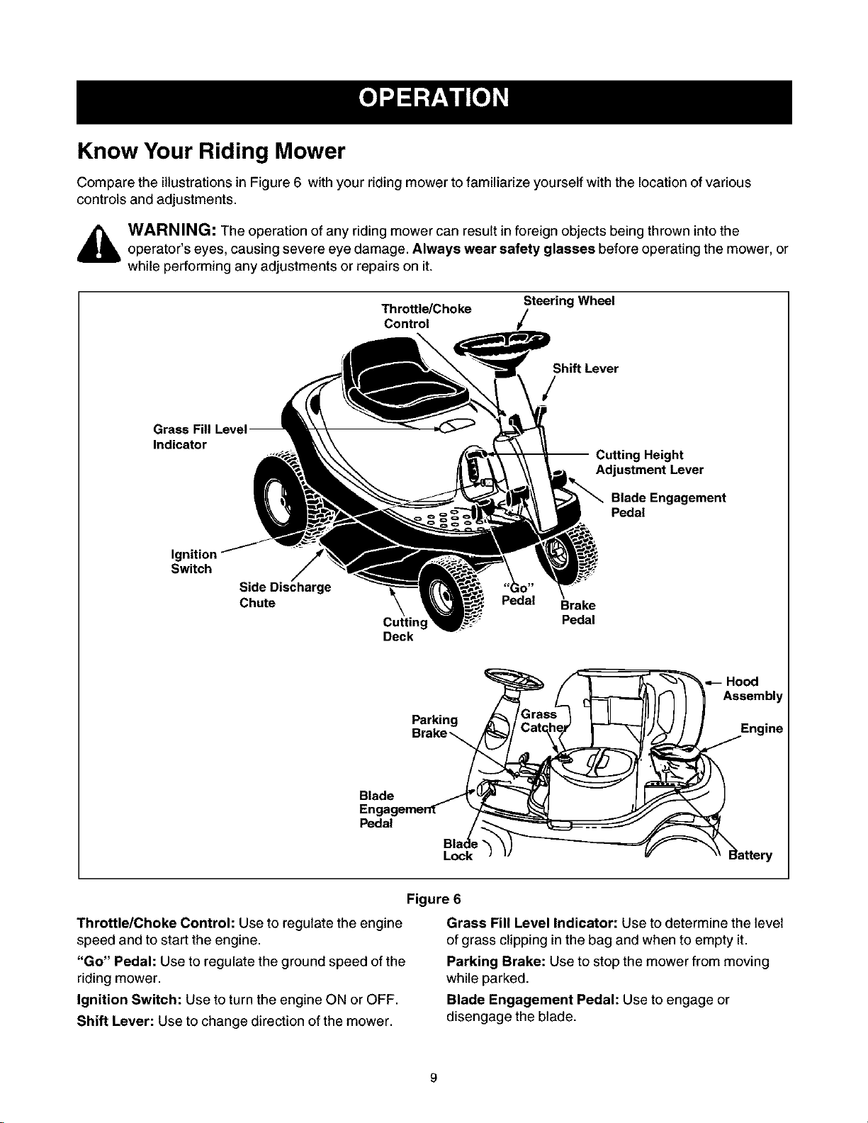
Know Your Riding Mower
Compare the illustrations in Figure 6 with your riding mower to familiarize yourself with the location of various
controls and adjustments.
,_ WARNING: The operation of any riding mower can result in foreign objects being thrown into theoperator's eyes, causing severe eye damage. Always wear safety glasses before operating the mower, or
while performing any adjustments or repairs on it.
Indicator
Ignition
Switch
Side Discharge
Chute
Throttle/Choke
Control
Cutting
Deck
Steering Wheel
Shift Lever
Pedal
g Height
Adjustment Lever
Blade Engagement
Pedal
Brake
Pedal
Blade
En
Pedal
Throttle/Choke Control: Use to regulate the engine
speed and to start the engine.
"Go" Pedal: Use to regulate the ground speed of the
riding mower.
Ignition Switch: Use to turn the engine ON or OFF.
Shift Lever: Use to change direction of the mower.
Parking
Lock
Figure 6
Grass Fill Level Indicator: Use to determine the level
of grass clipping in the bag and when to empty it.
Parking Brake: Use to stop the mower from moving
while parked.
Blade Engagement Pedal: Use to engage or
disengage the blade.
BladeLock:Usetolockbladeattheengagedposition.
CuttingHeightAdjustmentLever:Usetoraiseand
lowerthecuttingdeckwhichdeterminesthecutting
height.
BrakePedal:Usetostopthemower'sforwardor
reversemotion.
• Knowlocationandfunctionofallcontrols.
• Besurebladesandenginearestoppedbefore
placinghandsorfeetnearblades.
• Beforeleavingoperator'sposition,disengage
blade(s),placetheshiftleverinneutral,engage
parkingbrake,shutengineoffandremovekey.
Stopping the Riding Mower
1. Release blade engagement pedal all the way.
2. Release "Go" Pedal and depress the brake pedal.
3. When the mower comes to a complete stop, place
the shift lever in neutral.
4. Engage the parking brake by pulling up on the
parking brake knob.
5. Turn the ignition key to OFF position and remove
the key.
Emergency Stopping
To stop the vehicle immediately in an emergency, raise
your body up and off the seat.
Safety Interlock
This unit isequipped with a safety interlock system for
your protection. The interlock safety switches are
connected to the brake pedal, the blade engagement
pedal, the shift lever, and the seat.
The purpose of the safety interlock system is threefold:
• To prevent the engine from starting unless the
brake pedal is depressed and the blade
engagement pedal is disengaged;
• To shut off the engine if the blade pedal is not
disengaged when the shift lever is put into reverse;
and
• To shut the engine off when the operator leaves the
seat without engaging the parking brake.
,_ WARNING: To avoid the risk of seriousinjury, do not operate the riding mower ifthe
interlock system is malfunctioning.
Using Shift Lever
This lever is used to regulate direction of the riding
mower. It can be set at forward, neutral, or reverse
settings. These settings are marked F, N, and R
respectively on the unit. This unit is designed not to
mow when the shift lever is in R position.
1. Before you move the shift lever to any ofthe
positions, depress the brake pedal and stop the
unit. Keep your foot on the brake
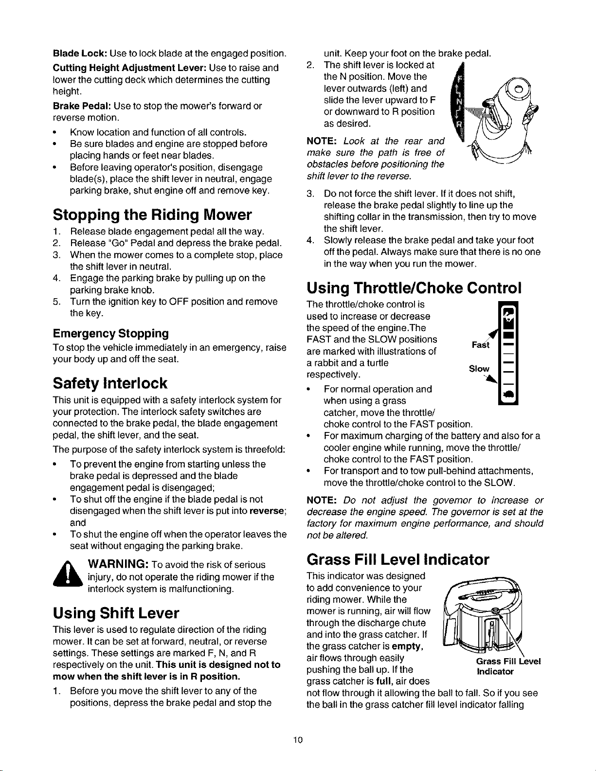
2,
The shift lever is locked at
the N position. Move the
lever outwards (left) and
slide the lever upward to F
or downward to R position
as desired.
NOTE: Look at the rear and
make sure the path is free of
obstacles before positioning the
shift lever to the reverse.
3. Do not force the shift lever. If it does not shift,
release the brake pedal slightly to line up the
shifting collar in the transmission, then try to move
the shift lever.
4. Slowly release the brake pedal and take your foot
off the pedal. Always make sure that there is no one
in the way when you run the mower.
_edal.
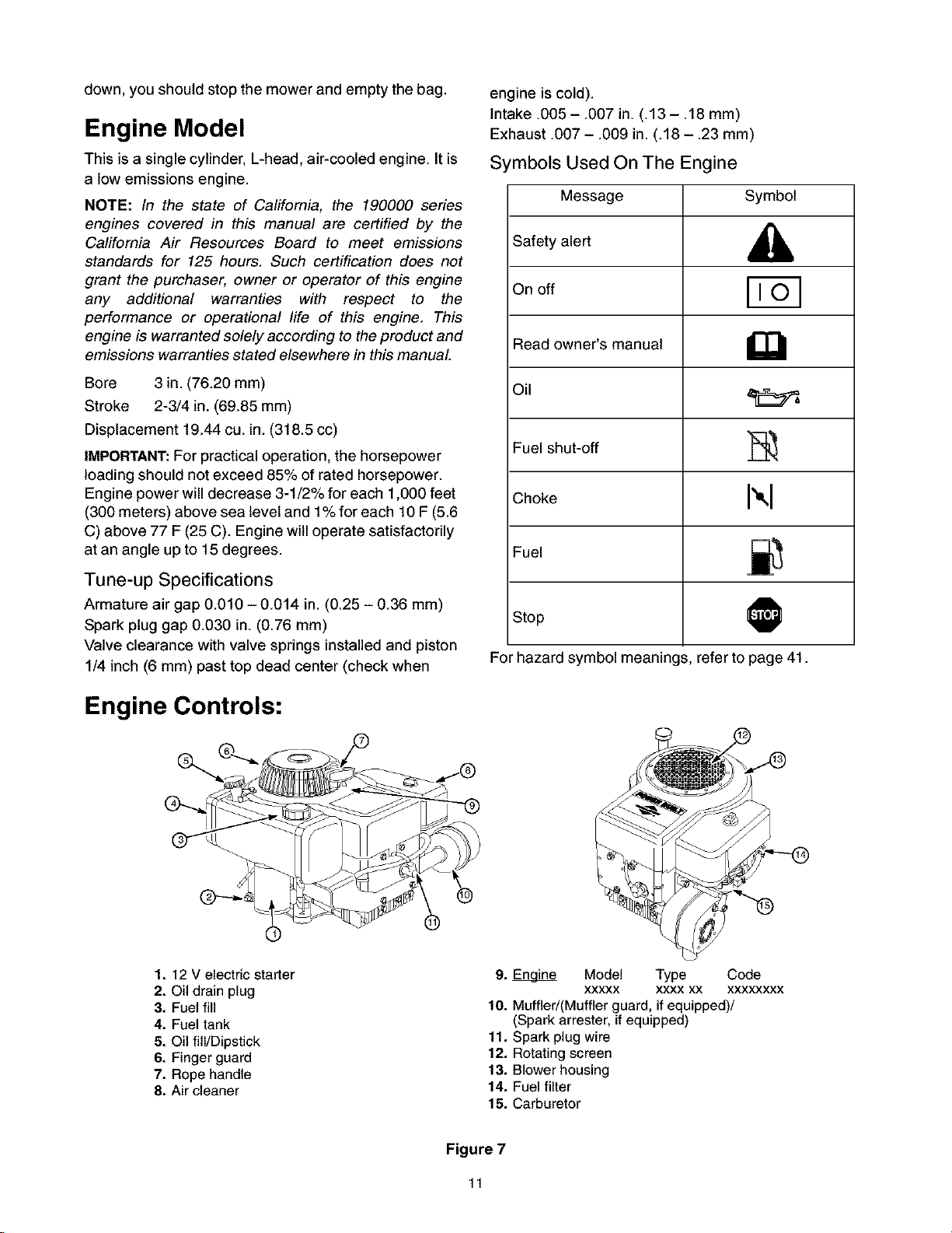
Using Throttle/Choke Control
used to increase or decrease
the speed of the engine.The
FAST and the SLOW positions
are marked with illustrations of
a rabbit and a turtle
respectively.
The throttle/choke control is II_II__
• For normal operation and
when using a grass
catcher, move the throttle/
choke control to the FAST position.
• For maximum charging of the battery and also for a
cooler engine while running, move the throttle/
choke control to the FAST position.
• For transport and to tow pull-behind attachments,
move the throttle/choke control to the SLOW.
NOTE: Do not adjust the governor to increase or
decrease the engine speed. The governor is set at the
factory for maximum engine performance, and should
not be altered.
Grass Fill Level Indicator
This indicator was designed
to add convenience to your
riding mower. While the
mower is running, air will flow
through the discharge chute
and into the grass catcher. If
the grass catcher is empty,
air flows through easily
pushing the ball up. If the
grass catcher is full, air does
not flow through it allowing the
the ball inthe grass catcher fill
ball to fall. So if you see
level indicator falling
Grass Fill Level
Indicator
10
down,youshouldstopthemowerandemptythebag.
Engine Model
This is a single cylinder, L-head, air-cooled engine. It is
a low emissions engine.
NOTE: In the state of California, the 190000 series
engines covered in this manual are certified by the
California Air Resources Board to meet emissions
standards for 125 hours. Such certification does not
grant the purchaser, owner or operator of this engine
any additional warranties with respect to the
performance or operational life of this engine. This
engine is warranted solely according to the product and
emissions warranties stated elsewhere in this manual
Bore 3 in. (76.20 mm)
Stroke 2-3/4 in. (69.85 mm)
Displacement 19.44 cu. in. (318.5 cc)
IMPORTANT:For practical operation, the horsepower
loading should not exceed 85% of rated horsepower.
Engine power will decrease 3-1/2% for each 1,000 feet
(300 meters) above sea level and 1%for each 10 F (5.6
C) above 77 F (25 C). Engine will operate satisfactorily
at an angle up to 15 degrees.
Tune-up Specifications
Armature air gap 0.010 - 0.014 in. (0.25 - 0.36 mm)
Spark plug gap 0.030 in. (0.76 mm)
Valve clearance with valve springs installed and piston
1/4 inch (6 mm) past top dead center (check when
engine iscold).
Intake .005 - .007 in. (.13 - .18 mm)
Exhaust .007- .009 in. (.18- .23 mm)
Symbols Used On The Engine
Message Symbol
Safety alert ,_
On off
Read owner's manual
Fuel shut-off _,
Choke I",1
Fuel =_
Stop
For hazard symbol meanin(
s, refer to page 41.
O
Engine Controls:
1. 12 V electric starter
2. Oil drain plug
3. Fuel fill
4. Fuel tank
5. Oil fill/Dipstick
6. Finger guard
7. Rope handle
8. Air cleaner
®
9. _ Model Type Code
xxxxx xxxx xx xxxxxxxx
10. Muffled(Muffler guard, if equipped)/
(Spark arrester, if equipped)
11. Spark plug wire
12. Rotating screen
13. Blower housing
14. Fuel filter
15. Carburetor
Figure 7
11
Using Parking Brake
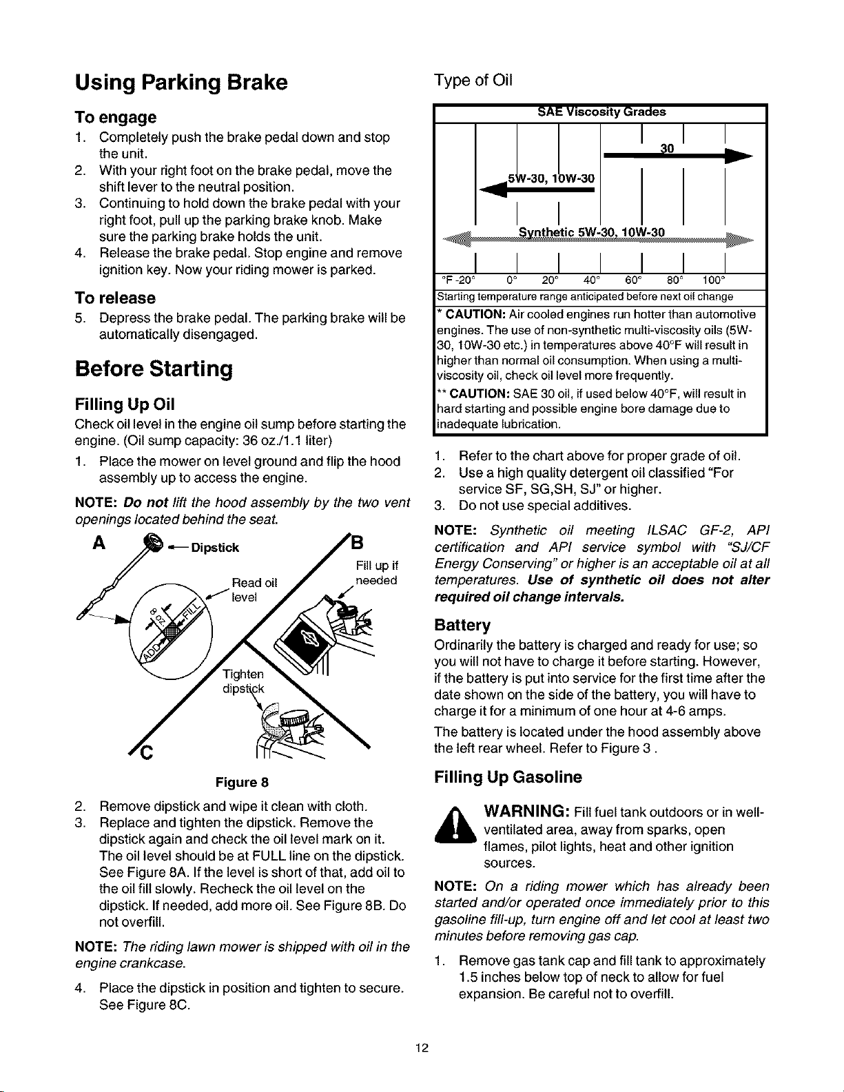
Type of Oil
To engage
1. Completely push the brake pedal down and stop
the unit.
2. With your right foot on the brake pedal, move the
shift lever to the neutral position.
3. Continuing to hold down the brake pedal with your
right foot, pull up the parking brake knob. Make
sure the parking brake holds the unit.
4. Release the brake pedal. Stop engine and remove
ignition key. Now your riding mower isparked.
To release
5. Depress the brake pedal. The parking brake will be
automatically disengaged.
Before Starting
Filling Up Oil
Check oil level inthe engine oil sump before starting the
engine. (Oil sump capacity: 36 oz./1.1 liter)
1. Place the mower on level ground and flip the hood
assembly up to access the engine.
NOTE: Do not lift the hood assembly by the two vent
openings located behind the seat.
A _ Dipstick
Fill up if
Read oil needed
/ level /
SAE Viscosity Grades
I
_,==5' V-30, 1 JW-30
I I
:0
I I
°F -20 ° 0° 20 ° 40° 60 ° 80° 100°
Starting temperature range anticipated before next oil change
* CAUTION: Air cooledengines runhotter than automotive
engines. The use of non-syntheticmulti-viscosity oils (5W-
30, 10W-30 etc.)in temperaturesabove 40°F will resultin
higherthan normal oil consumption.When using amulti-
viscosity oil,check oil level morefrequently.
** CAUTION: SAE 30 oil, ifused below40°F, will result in
hardstarting and possibleengine bore damagedue to
inadequatelubrication.
1. Refer to the chart above for proper grade of oil.
2. Use a high quality detergent oil classified "For
service SF, SG,SH, SJ" or higher.
3. Do not use special additives.
NOTE: Synthetic oil meeting ILSAC GF-2, API
certification and API service symbol with "SJ/CF
Energy Conserving" or higher is an acceptable oil at all
temperatures. Use of synthetic oil does not alter
required oil change intervals.
I I I I I
Figure 8
2,
Remove dipstick and wipe itclean with cloth.
3.
Replace and tighten the dipstick. Remove the
dipstick again and check the oil level mark on it.
The oil level should be at FULL line on the dipstick.
See Figure 8A. If the level is short ofthat, add oil to
the oil fill slowly. Recheck the oillevel on the
dipstick. If needed, add more oil. See Figure 8B. Do
not overfill.
NOTE: The riding lawn mower is shipped with oil in the
engine crankcase.
4. Place the dipstick in position and tighten to secure.
See Figure 8C.
Battery
Ordinarily the battery is charged and ready for use; so
you will not have to charge it before starting. However,
if the battery is put into service for the first time after the
date shown on the side of the battery, you wilt have to
charge itfor a minimum of one hour at 4-6 amps.
The battery is located under the hood assembly above
the left rear wheel. Refer to Figure 3.
Filling Up Gasoline
WARNING: Fill fuel tank outdoors or in well-
ventilated area, away from sparks, open
flames, pilot lights, heat and other ignition
sources.
NOTE: On a riding mower which has already been
started and/or operated once immediately prior to this
gasoline fill-up, turn engine off and let cool at least two
minutes before removing gas cap.
1. Remove gas tank cap and fill tank to approximately
1.5 inches below top of neck to allow for fuel
expansion. Be careful not to overfill.
12
2. Replace cap on the gas tank and tighten to secure. Stopping the Riding Mower
NOTE: If fuel spills on part of engine or vehicle, wait
until it evaporates before starting engine.
Type of Gasoline
• Use clean, fresh, regular unleaded gasoline with
minimum 77 octane rating.
• Do not use gasoline mixed with methanol, or
gasoline which has been stored for more than 30
days. Always purchase fuel in quantity that can be
used up within 30 days. Fresh fuel prevents gum
from forming in the fuel system or on carburetor.
• Do not mix gasoline with engine oil.
NOTE: Some fuels, called oxygenated or reformulated
gasoline, are blended with alcohol or ether. Using these
blends frequently can damage the fuel system or affect
performance. If engine performance is affected, use
gasoline with Iower percentage of alcohol or ether.
Starting Engine
1. Attach the wire to the spark plug.
2. Depress the brake pedal with your right foot.
3. Set throttle/choke control in the CHOKE position
(all the way forward).
4. Place the shift lever in the NEUTRAL position.
5. Turn ignition key to the START position. Once the
engine starts, let key return to ON position.
6. Move throttle/choke control out of CHOKE position
and into FAST throttle position.
See page 10for detailed instruction.
NOTE: Do not leave the key in the ON position when
you are not operating the mower. Such action will drain
the battery dead.
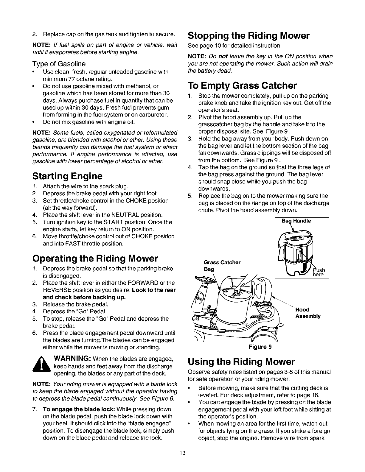
To Empty Grass Catcher
1. Stop the mower completely, pull up on the parking
brake knob and take the ignition key out. Get off the
operator's seat.
2. Pivot the hood assembly up. Pull up the
grasscatcher bag by the handle and take it to the
proper disposal site. See Figure 9.
3. Hold the bag away from your body. Push down on
the bag lever and let the bottom section of the bag
fall downwards. Grass clippings wilt be disposed off
from the bottom. See Figure 9.
4. Tap the bag on the ground so that the three legs of
the bag press against the ground. The bag lever
should snap close while you push the bag
downwards.
5. Replace the bag on to the mower making sure the
bag is placed on the flange on top of the discharge
chute. Pivot the hood assembly down.
Operating the Riding Mower
1. Depress the brake pedal so that the parking brake
isdisengaged.
2. Place the shift lever in either the FORWARD or the
REVERSE position as you desire. Look to the rear
and check before backing up.
3. Release the brake pedal.
4. Depress the "Go" Pedal.
5. To stop, release the "Go" Pedal and depress the
brake pedal.
6. Press the blade engagement pedal downward until
the blades are turning.The blades can be engaged
either while the mower is moving or standing.
_ ARNING: When the blades are engaged,keep hands and feet away from the discharge
opening, the blades or any part of the deck.
NOTE: Your riding mower is equipped with a blade lock
to keep the blade engaged without the operator having
to depress the blade pedal continuously. See Figure 6.
7. To engage the blade lock: While pressing down
on the blade pedal, push the blade lock down with
your heel. It should click into the "blade engaged _
position. To disengage the blade lock, simply push
down on the blade pedal and release the lock.
Grass Catcher
Bag
Assembly
Figure 9
ush
re
Using the Riding Mower
Observe safety rules listed on pages 3-5 of this manual
for safe operation of your riding mower.
• Before mowing, make sure that the cutting deck is
leveled. For deck adjustment, refer to page 16.
• You can engage the blade by pressing on the blade
engagement pedal with your left foot while sitting at
the operator's position.
• When mowing an area for the first time, watch out
for objects lying on the grass. If you strike a foreign
object, stop the engine. Remove wire from spark
13
plugandthoroughlyinspecttheridingmowerfor
anydamage.Repairthedamagebeforeoperating
itagain.
• Avoidscalpingthelawnbyadjustingthecutting
heightupwardsand/orsharpeningtheblades.
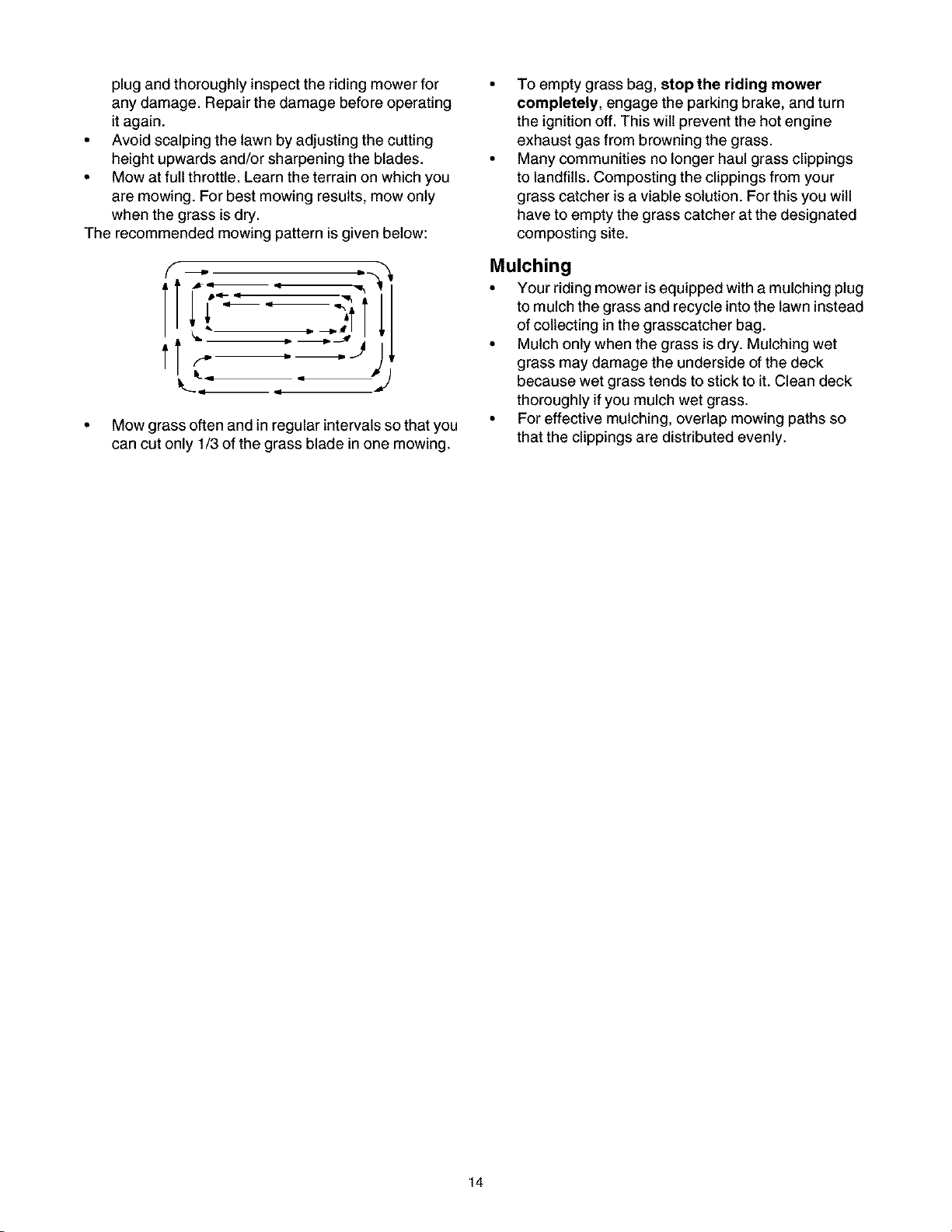
• Mowatfullthrottle.Learntheterrainonwhichyou
aremowing.Forbestmowingresults,mowonly
whenthegrassisdry.
Therecommendedmowingpatternisgivenbelow:
To empty grass bag, stop the riding mower
completely, engage the parking brake, and turn
the ignition off. This wilt prevent the hot engine
exhaust gas from browning the grass.
Many communities no longer haul grass clippings
to landfills. Composting the clippings from your
grass catcher is a viable solution. For this you will
have to empty the grass catcher at the designated
composting site.
f ._D
tr-
q
• Mow grass often and in regular intervals so that you
can cut only 1/3 of the grass blade in one mowing.
Mulching
• Your riding mower is equipped with a mulching plug
to mulch the grass and recycle into the lawn instead
of collecting in the grasscatcher bag.
• Mulch only when the grass is dry. Mulching wet
grass may damage the underside of the deck
because wet grass tends to stick to it.Clean deck
thoroughly if you mulch wet grass.
• For effective mulching, overlap mowing paths so
that the clippings are distributed evenly.
14
Adjustments
9. Unlock parking brake and repeat the test described
above. Readjust if necessary.
_ WARNING: Do not make any adjustment tothe riding mower without first stopping engine
and disconnecting spark plug wire.
Brake Pedal
During normal operation of the riding mower, the brake
is subject to wear and tear. Check the brake
periodically by carrying out the following test:
1. Release the parking brake and place the riding
mower in neutral. Depress the brake pedal and try
to roll the riding mower. The tractor should not
move. If the tractor moves, adjust the brake.
WARNING: Do not adjust the brake while
the engine is running. Be sure to block the
wheels of the riding mower before making any
adjustments on the brake cable.
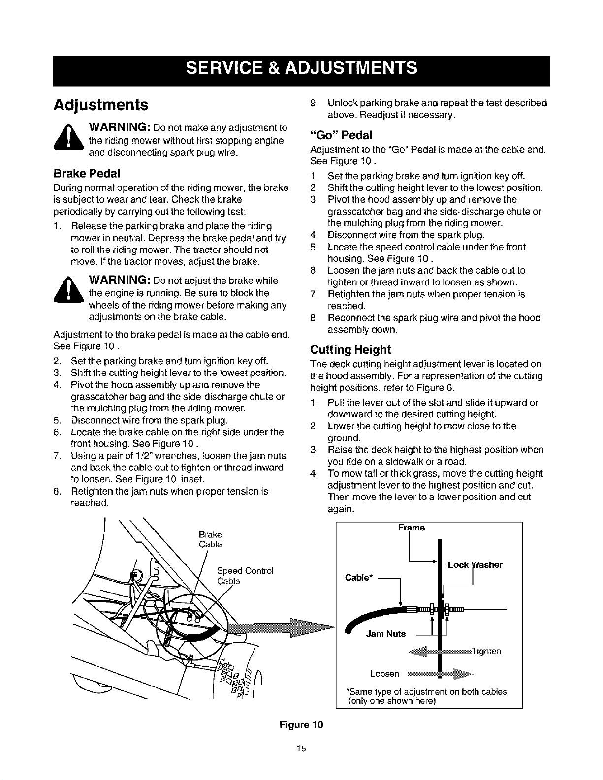
Adjustment to the brake pedal is made at the cable end.
See Figure 10.
2. Set the parking brake and turn ignition key off.
3. Shift the cutting height lever to the lowest position.
4. Pivot the hood assembly up and remove the
grasscatcher bag and the side-discharge chute or
the mulching plug from the riding mower.
5. Disconnect wire from the spark plug.
6. Locate the brake cable on the right side under the
front housing. See Figure 10.
7. Using a pair of 1/2_wrenches, loosen the jam nuts
and back the cable out to tighten or thread inward
to loosen. See Figure 10 inset.
8. Retighten the jam nuts when proper tension is
reached.
"Go" Pedal
Adjustment to the "Go" Pedal is made at the cable end.
See Figure 10.
1. Set the parking brake and turn ignition key off.
2. Shift the cutting height lever to the lowest position.
3. Pivot the hood assembly up and remove the
grasscatcher bag and the side-discharge chute or
the mulching plug from the riding mower.
4. Disconnect wire from the spark plug.
5. Locate the speed control cable under the front
housing. See Figure 10.
6. Loosen the jam nuts and back the cable out to
tighten or thread inward to loosen as shown.
7. Retighten the jam nuts when proper tension is
reached.
8. Reconnect the spark plug wire and pivot the hood
assembly down.
Cutting Height
The deck cutting height adjustment lever is located on
the hood assembly. For a representation of the cutting
height positions, refer to Figure 6.
1. Pull the lever out of the slot and slide it upward or
downward to the desired cutting height.
2. Lower the cutting height to mow close to the
ground.
3. Raise the deck height to the highest position when
you ride on a sidewalk or a road.
4. To mow tait or thick grass, move the cutting height
adjustment lever to the highest position and cut.
Then move the lever to a lower position and cut
again.
Brake
Cable
;ontrol
asher
Cable*
Loosen
*Same type of adjustment on both cables
(only one shown here)
Figure 10
15
Seat Position
The seat position on the riding mower can be adjusted
to maximize the operator's convenience.
1. Stop the mower completely and engage the parking
brake. Turn ignition off.
2. Pivot the hood assembly up.
3. Loosen the four self-tapping screws on the bottom
of the seat.
4. Slide the seat forward or backward in the slot, and
position it as desired. Retighten the four screws.
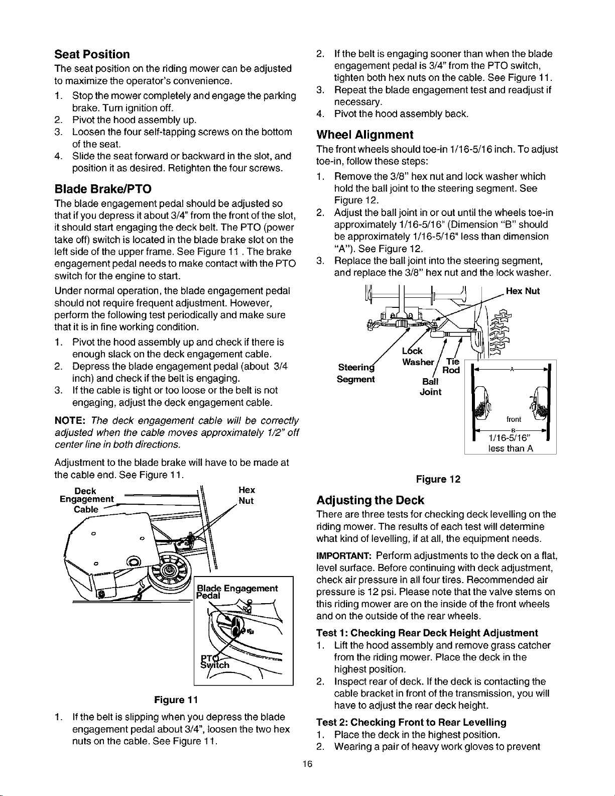
Blade Brake/PTO
The blade engagement pedal should be adjusted so
that ifyou depress it about 3/4" from the front of the slot,
it should start engaging the deck belt. The PTO (power
take off) switch is located in the blade brake slot on the
left side of the upper frame. See Figure 11. The brake
engagement pedal needs to make contact with the PTO
switch for the engine to start.
Under normal operation, the blade engagement pedal
should not require frequent adjustment. However,
perform the following test periodically and make sure
that it is in fine working condition.
1. Pivot the hood assembly up and check if there is
enough slack on the deck engagement cable.
2. Depress the blade engagement pedal (about 3/4
inch) and check if the belt is engaging.
3. If the cable is tight or too loose or the belt is not
engaging, adjust the deck engagement cable.
2. If the belt is engaging sooner than when the blade
engagement pedal is 3/4" from the PTO switch,
tighten both hex nuts on the cable. See Figure 11.
3. Repeat the blade engagement test and readjust if
necessary.
4. Pivot the hood assembly back.
Wheel Alignment
The front wheels should toe-in 1/16-5/16 inch. To adjust
toe-in, follow these steps:
1. Remove the 3/8" hex nut and lock washer which
hold the ball joint to the steering segment. See
Figure 12.
2. Adjust the ball joint in or out until the wheels toe-in
approximately 1/16-5/16" (Dimension "B" should
be approximately 1/16-5/16" less than dimension
"A'). See Figure 12.
3. Replace the ball joint into the steering segment,
and replace the 3/8" hex nut and the lock washer.
Hex Nut
Steering Washer
Segment Ball
Joint
NOTE: The deck engagement cable will be correctly
adjusted when the cable moves approximately 1/2" off
center line in both directions.
Adjustment to the blade brake wilt have to be made at
the cable end. See Figure 11.
Deck Hex
Engagement Nut
Cable
Blade Engagement
Pedal
n
Figure 11
1,
If the belt is slipping when you depress the blade
engagement pedal about 3/4", loosen the two hex
nuts on the cable. See Figure 11.
1/16-5/16"
less than A
Figure 12
Adjusting the Deck
There are three tests for checking deck levelling on the
riding mower. The results of each test will determine
what kind of levelling, if at all, the equipment needs.
IMPORTANT: Perform adjustments to the deck on a flat,
level surface. Before continuing with deck adjustment,
check air pressure in nit four tires. Recommended air
pressure is 12 psi. Please note that the valve stems on
this riding mower are on the inside of the front wheels
and on the outside of the rear wheels.
Test 1: Checking Rear Deck Height Adjustment
1. Lift the hood assembly and remove grass catcher
from the riding mower. Place the deck in the
highest position.
2. Inspect rear of deck. If the deck is contacting the
cable bracket in front of the transmission, you will
have to adjust the rear deck height.
Test 2: Checking Front to Rear Levelling
1. Place the deck in the highest position.
2. Wearing a pair of heavy work gloves to prevent
16
injury,rotatethecuttingbladesothatitispointed
fronttobackandparalleltotherider.Depressand
lockthedeckengagementpedal.
3. Measurethedistancefromthefrontandtherear
tipsofthebladetotheground.Thefrontshouldbe
approximately1/4"to3/8"lowerthantherear.
4. Ifthedistanceishigher,levelthedeckfronttorear.
Test 3: Checking Side to Side Levelling
1. Place the deck in the highest position.
2. Wearing a pair of heavy work gloves to prevent
injury, rotate the cutting blade so that it is pointed
side to side and perpendicular to the rider. Depress
and lock the deck engagement pedal.
3. Measure the distance from the tips of the blade to
the ground.
4. If the two distances are unequal, level the deck
side to side.
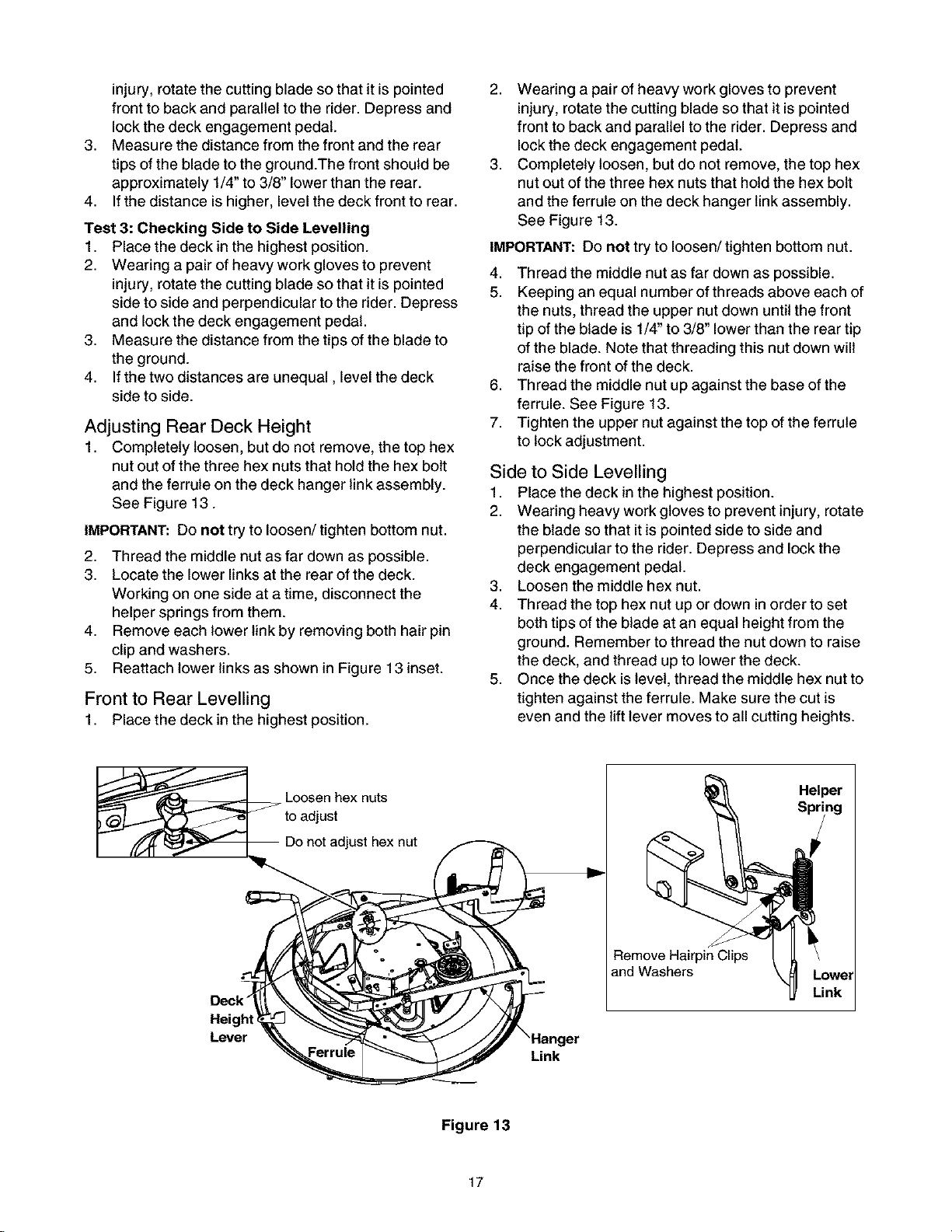
Adjusting Rear Deck Height
1. Completely loosen, but do not remove, the top hex
nut out of the three hex nuts that hold the hex bolt
and the ferrule on the deck hanger link assembly.
See Figure 13.
IMPORTANT: Do not try to loosen/tighten bottom nut.
2. Thread the middle nut as far down as possible.
3. Locate the lower links at the rear of the deck.
Working on one side at a time, disconnect the
helper springs from them.
4. Remove each lower link by removing both hair pin
clip and washers.
5. Reattach lower links as shown in Figure 13 inset.
Front to Rear Levelling
1. Place the deck in the highest position.
2. Wearing a pair of heavy work gloves to prevent
injury, rotate the cutting blade so that it is pointed
front to back and parallel to the rider. Depress and
lock the deck engagement pedal.
3. Completely loosen, but do not remove, the top hex
nut out of the three hex nuts that hold the hex bolt
and the ferrule on the deck hanger link assembly.
See Figure 13.
IMPORTANT: Do not try to loosen/tighten bottom nut.
4. Thread the middle nut as far down as possible.
5. Keeping an equal number of threads above each of
the nuts, thread the upper nut down until the front
tip of the blade is 1/4" to 3/8" lower than the rear tip
of the blade. Note that threading this nut down will
raise the front of the deck.
6. Thread the middle nut up against the base ofthe
ferrule. See Figure 13.
7. Tighten the upper nut against the top of the ferrule
to lock adjustment.
Side to Side Levelling
1. Place the deck in the highest position.
2. Wearing heavy work gloves to prevent injury, rotate
the blade so that it is pointed side to side and
perpendicular to the rider. Depress and lock the
deck engagement pedal.
3. Loosen the middle hex nut.
4. Thread the top hex nut up or down in order to set
both tips of the blade at an equal height from the
ground. Remember to thread the nut down to raise
the deck, and thread up to lower the deck.
5. Once the deck is level, thread the middle hex nutto
tighten against the ferrule. Make sure the cut is
even and the lift lever moves to all cutting heights.
Deck"
Lever
Loosen hex nuts
to adjust
)t adjust hex nut
Helper ]
Remove Hairpin Clips
and Washers
'Hanger
Link
Figure 13
17
Adjusting the Carburetor
Differences in fuel, temperature, altitude or load may
require minor carburetor adjustments. The carburetor
on this engine is equipped with an idle mixture valve
with a limiter which allows some adjustment, and an
idle speed adjustment screw. Remember that the air
cleaner and its cover must be assembled to the
carburetor before re-starting the engine. Refer to page
22 for details.
NOTE: Engines, operated at approximately 3000 to
5000 feet above sea level, may require a high altitude
carburetor nozzle. If your riding mower performs
erratically, contact Sears service center for the nozzle.
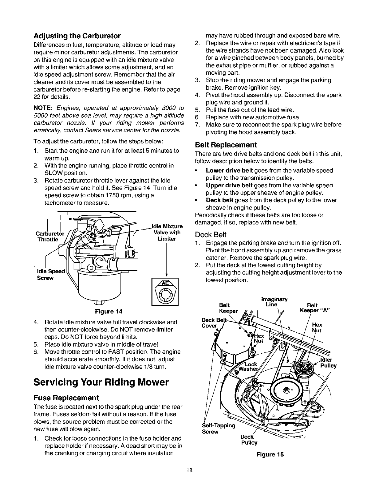
To adjust the carburetor, follow the steps below:
1. Start the engine and run it for at least 5 minutes to
warm up.
2. With the engine running, place throttle control in
SLOW position.
3. Rotate carburetor throttle lever against the idle
speed screw and hold it. See Figure 14. Turn idle
speed screw to obtain 1750 rpm, using a
tachometer to measure.
Valve with
Limiter
IdleSpeed
Screw
may have rubbed through and exposed bare wire.
2. Replace the wire or repair with electrician's tape if
the wire strands have not been damaged. Also look
for a wire pinched between body panels, burned by
the exhaust pipe or muffler, or rubbed against a
moving part.
3. Stop the riding mower and engage the parking
brake. Remove ignition key.
4. Pivot the hood assembly up. Disconnect the spark
plug wire and ground it.
5. Pull the fuse out of the lead wire.
6. Replace with new automotive fuse.
7. Make sure to reconnect the spark plug wire before
pivoting the hood assembly back.
Belt Replacement
There are two drive belts and one deck belt in this unit;
follow description below to identify the belts.
• Lower drive belt goes from the variable speed
pulley to the transmission pulley.
• Upper drive belt goes from the variable speed
pulley to the upper sheave of engine pulley.
• Deck belt goes from the deck pulley to the lower
sheave in engine pulley.
Periodically check ifthese belts are too loose or
damaged. Ifso, replace with new belt.
Deck Belt
1. Engage the parking brake and turn the ignition off.
Pivot the hood assembly up and remove the grass
catcher. Remove the spark plug wire.
2. Put the deck at the lowest cutting height by
adjusting the cutting height adjustment lever to the
lowest position.
Figure 14
4,
Rotate idle mixture valve full travel clockwise and
then counter-clockwise. Do NOT remove limiter
caps. Do NOT force beyond limits.
5,
Place idle mixture valve in middle of travel.
6.
Move throttle control to FAST position. The engine
should accelerate smoothly. If it does not, adjust
idle mixture valve counter-clockwise 1/8 turn.
Servicing Your Riding Mower
Fuse Replacement
The fuse is located next tothe spark plugunder the rear
frame. Fuses seldom fail without a reason. Ifthe fuse
blows, the source problem must be corrected or the
new fuse will blow again.
1. Check for loose connections in the fuse holder and
replace holder if necessary. A dead short may be in
the cranking or charging circuit where insulation
Belt Line Belt
Imaginary
Keeper Keeper "A"
Pulley
Self-Tapping
Screw
Decl(
Pulley
Figure 15
18
3. Usinga1/2"socketwrench,removetwoself-
tappingscrews,lockwasherandhexnutthathold
thedeckbeltcovertothedeck.SeeFigure15.For
this,youwillhavetoworkfromthetopleftsideof
theridingmower.Removethebeltcover.
4. Usinga9/16"wrench,loosenthehexnutonthe
idlerpulley.SeeFigure15.
5. Removebeltfromarounddeckpulley,idlerpulley,
andtheenginepulley.
6. Placethenewbeltaroundthedeckpulleyandthe
enginepulleymakingsurethatthebeltisrouted
insidethebeltkeepers.Therearetwobeltkeepers
underthegrasscatcher,oneontheidlerandthe
otherunderthedeckbeltcover.SeeFigure15.
7. Reinstalldeckbeltcoverandsecurewithtwoeach
ofself-tappingscrew,lockwasherandhexnut.
NOTE:Belt keeper "A" must be mounted on the outside
of the belt.
8. Make sure to align the belt keeper in line with the
frame. See Figure 16.
NOTE: An imaginary line between the belt keeper and
idler pulley should be parallel to frame. See Figure 15.
3. Using a 9/16" socket, remove bolt, spacer and the
flat washer from the variable speed pulley.
4. Drop the pulley down and remove the belt.
5. Replace new belt and reassemble.
IMPORTANT:Make sure that the belt is routed inside of
belt keeper, and the belt keeper is reassembled in the
same location from where itwas removed.
Upper Variable Speed Belt
1. Remove the engine pulley using a 5/8" socket
wrench with a 6" extension. The engine pulley is
located in front of the transmission.
2. Drop the engine pulley down and remove the belt
from around it.
3. Push the idler bracket to the right and remove the
belt. See Figure 16.
4. Replace belt and reassemble.
Battery
The battery is located under the hood assembly. The
positive battery terminal is marked Pos. (+). The
negative battery terminal is marked Neg. (-).
9. Replace the grass catcher and pivot the hood
assembly back.
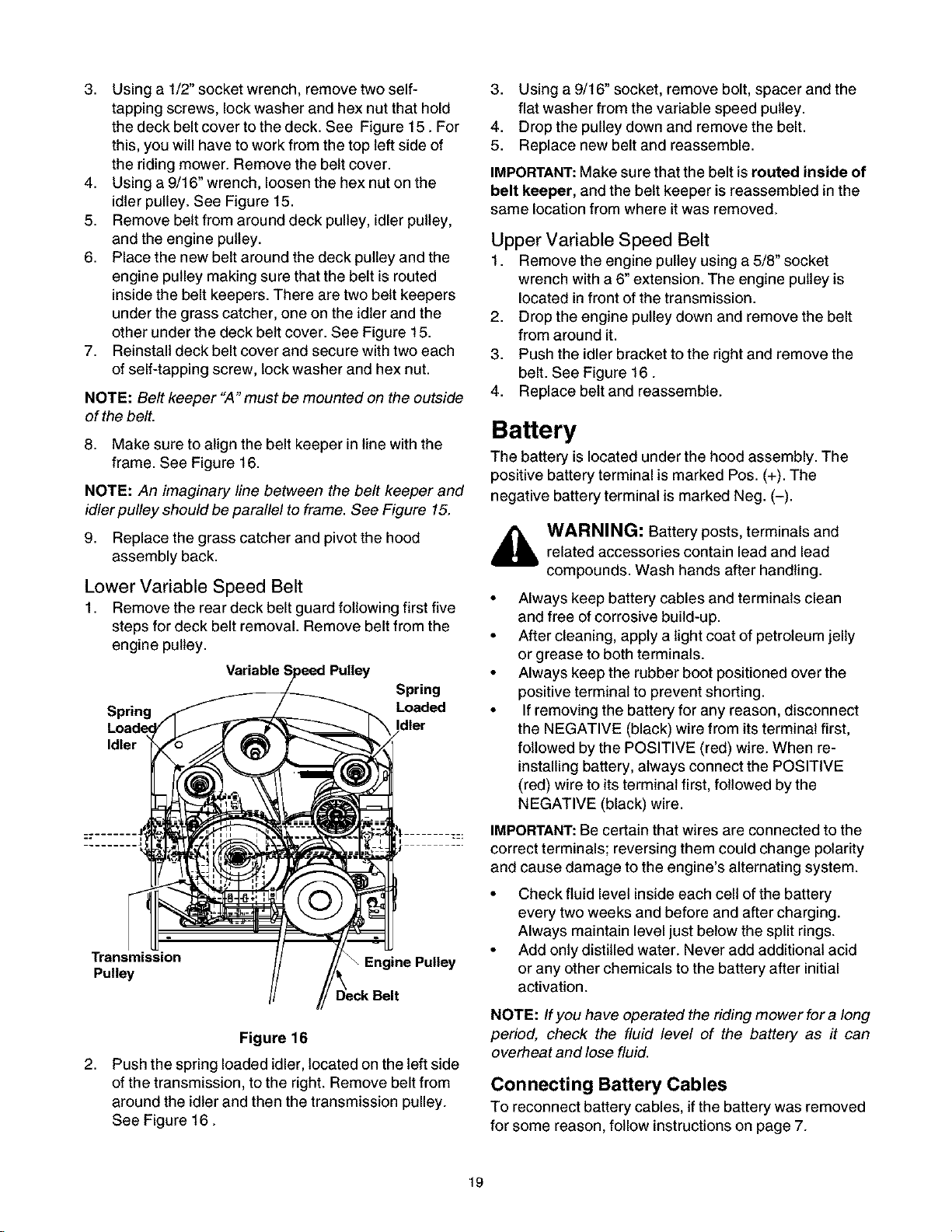
Lower Variable Speed Belt
1. Remove the rear deck belt guard following first five
steps for deck belt removal. Remove belt from the
engine pulley.
Variabh
Spring
Spring Loaded
Idler
Transmission _ Engine Pulley
Pulley
,_ WARNING: Battery posts, terminals and
• Always keep battery cables and terminals clean
• After cleaning, apply a light coat of petroleum jelly
• Always keep the rubber boot positioned over the
• If removing the battery for any reason, disconnect
IMPORTANT:Be certain that wires are connected to the
correct terminals; reversing them could change polarity
and cause damage to the engine's alternating system.
• Check fluid level insideeach cell of the battery
• Add only distilled water. Never add additional acid
related accessories contain lead and lead
compounds. Wash hands after handling.
and free of corrosive build-up.
or grease to both terminals.
positive terminal to prevent shorting.
the NEGATIVE (black) wire from its terminal first,
followed by the POSITIVE (red) wire. When re-
installing battery, always connect the POSITIVE
(red) wire to its terminal first, followed by the
NEGATIVE (black) wire.
every two weeks and before and after charging.
Always maintain level just below the split rings.
or any other chemicals to the battery after initial
activation.
Figure 16
2,
Push the spring loaded idler, located on the left side
of the transmission, to the right. Remove belt from
around the idler and then the transmission pulley.
See Figure 16.
NOTE: If you have operated the riding mower for a long
period, check the fluid level of the battery as it can
overheat and lose fluid.
Con necti ng Battery Cables
To reconnect battery cables, if the battery was removed
for some reason, follow instructions on page 7.
19
General Recommendations
,_ WARNING: Always stop engine and disconnect spark plug wire before any maintenance or adjustments.Always maintain safety and follow instructions given below closely for smooth completion of job.
The warranty on this riding mower does not cover items that have been subjected to operator abuse or
negligence• To receive full value from the warranty, operator must maintain the riding mower as instructed in
this manual. Refer to the Maintenance Schedule below•
We do not recommend the use of pressure washers or garden hose to clean your unit• These may cause
damage to electrical components, spindles, pulleys, bearings or the engine• The use of water may shorten life
of your riding mower and reduce its serviceability
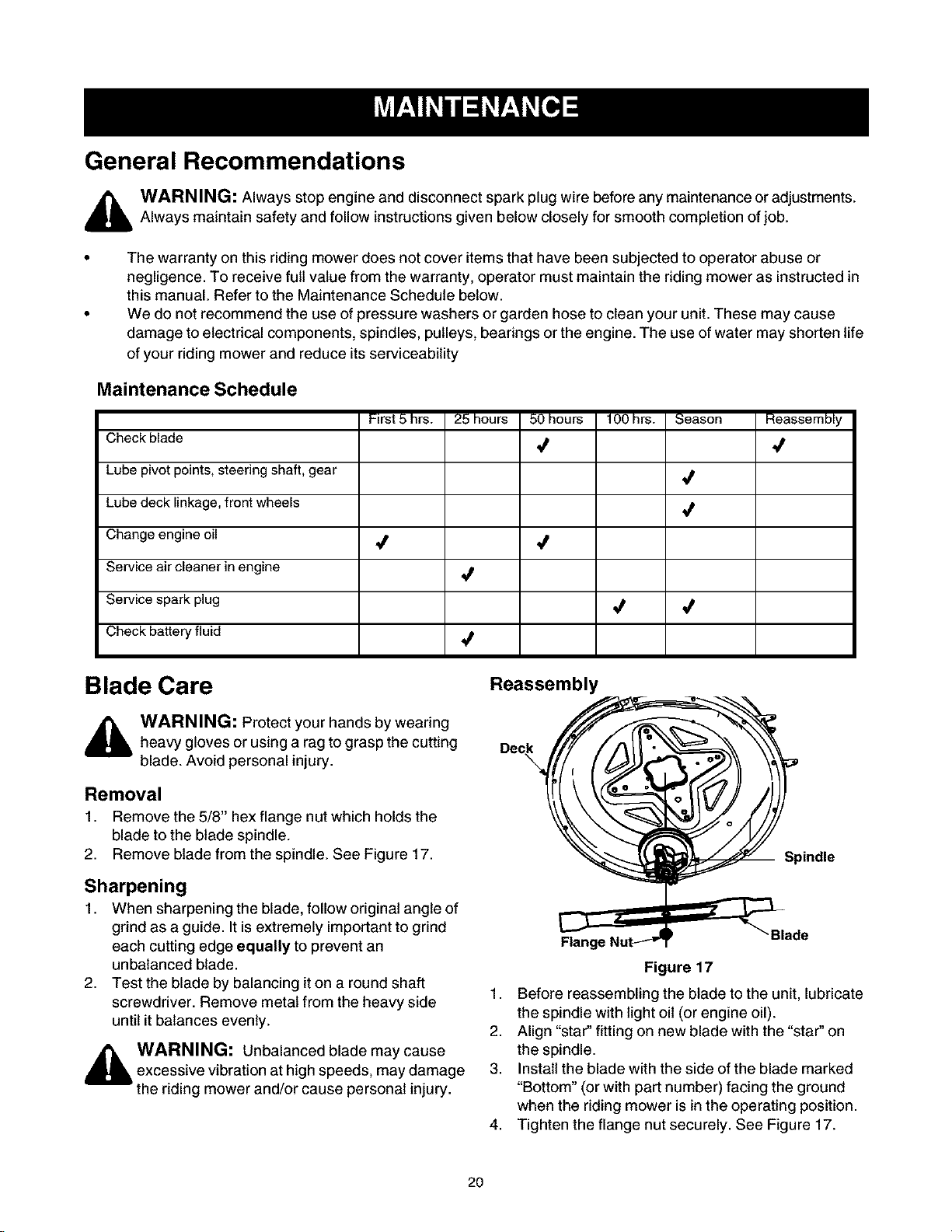
Maintenance Schedule
First5 hrs. 25 hours 50 hours 100hrs. Season Reassembly
Check blade
Lubepivot pl
Lube pivot points, steering shaft, gear
Lubedeck lir
Lube deck linkage, front wheels
Changeengi
Change engine oil
Service air cl
Service air cleaner in engine
Service spark plug
•/ ./
,/
•/ 4
Check battery fluid
Blade Care
WARNING: Protect your hands by wearing
WARI
heavy gloves or using a rag to grasp the cutting
heavy !
blade.,
blade. Avoid personal injury.
Removal
1. Remove th_
Remove the 5/8" hex flange nut which holds the
blade to the
blade to the blade spindle.
2. Remove bl_
Remove blade from the spindle. See Figure 17.
Sharpening
When sharpening the blade, follow original angle of
grind as a guide• It isextremely important to grind
each cutting edge equally to prevent an
unbalanced blade•
2,
Test the blade by balancing it on a round shaft
screwdriver• Remove metal from the heavy side
until it balances evenly.
_lb WARNING: Unbalanced blade may cause
excessive vibration at high speeds, may damage
the riding mower and/or cause personal injury.
,/
Reassembly
Deck /f//aI_ _
Spindle
Flange Nut-_'3"
Figure 17
1. Before reassembling the blade to the unit, lubricate
the spindle with light oil (or engine oil).
2. Align "star" fitting on new blade with the "star" on
the spindle•
3. Install the blade with the side of the blade marked
"Bottom" (or with part number) facing the ground
when the riding mower isin the operating position•
4. Tighten the flange nut securely• See Figure 17.
Blade
2O
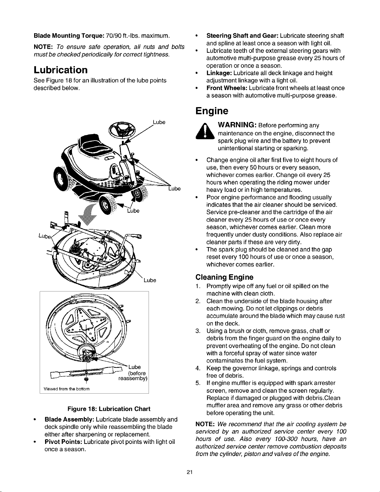
Blade Mounting Torque: 70/90 ft.-tbs, maximum.
NOTE: To ensure safe operation, all nuts and bolts
must be checked periodically for correct tightness.
Lubrication
See Figure 18 for an illustration of the lube points
described below.
Lube
Lube
• Steering Shaft and Gear: Lubricate steering shaft
and spline at least once a season with light oil.
• Lubricate teeth of the external steering gears with
automotive multi-purpose grease every 25 hours of
operation or once a season.
• Linkage: Lubricate all deck linkage and height
adjustment linkage with a light oil.
• Front Wheels: Lubricate front wheels at least once
a season with automotive multi-purpose grease.
Engine
WARNING: Before performing any
maintenance on the engine, disconnect the
spark plug wire and the battery to prevent
unintentional starting or sparking.
• Change engine oil after first five to eight hours of
use, then every 50 hours or every season,
whichever comes earlier. Change oil every 25
hours when operating the riding mower under
heavy load or in high temperatures.
• Poor engine performance and flooding usually
indicates that the air cleaner should be serviced.
Service pre-cleaner and the cartridge of the air
cleaner every 25 hours of use or once every
season, whichever comes earlier. Clean more
frequently under dusty conditions. Also replace air
cleaner parts ifthese are very dirty.
• The spark plug should be cleaned and the gap
reset every 100 hours of use or once a season,
whichever comes earlier.
be
Viewed from the bottom
Figure 18: Lubrication Chart
• Blade Assembly: Lubricate blade assembly and
deck spindle only while reassembling the blade
either after sharpening or replacement.
• Pivot Points: Lubricate pivot points with light oil
once a season.
Cleaning Engine
1. Promptly wipe off any fuel or oil spilled on the
machine with clean cloth.
2. Clean the underside of the blade housing after
each mowing. Do not let clippings or debris
accumulate around the blade which may cause rust
on the deck.
3. Using a brush or cloth, remove grass, chaff or
debris from the finger guard on the engine daily to
prevent overheating of the engine. Do not clean
with a forceful spray of water since water
contaminates the fuel system.
4. Keep the governor linkage, springs and controls
free of debris.
5. If engine muffler is equipped with spark arrester
screen, remove and clean the screen regularly.
Replace if damaged or plugged with debris.Clean
muffler area and remove any grass or other debris
before operating the unit.
NOTE: We recommend that the air cooling system be
serviced by an authorized service center every 100
hours of use. Also every 100-300 hours, have an
authorized service center remove combustion deposits
from the cylinder, piston and valves of the engine.
21
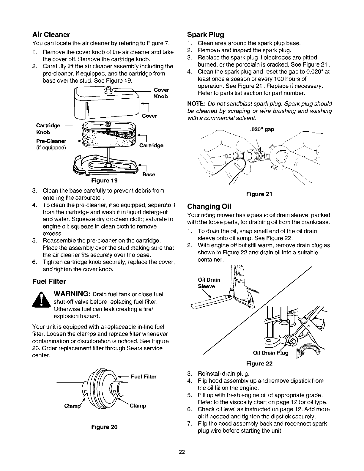
Air Cleaner
You can locate the air cleaner by refering to Figure 7.
1. Remove the cover knob of the air cleaner and take
the cover off. Remove the cartridge knob.
2. Carefully lift the air cleaner assembly including the
pre-cleaner, if equipped, and the cartridge from
base over the stud. See Figure 19.
Cover
Spark Plug
1. Clean area around the spark plug base.
2. Remove and inspect the spark plug.
3. Replace the spark plug if electrodes are pitted,
burned, or the porcelain iscracked. See Figure 21.
4. Clean the spark plug and reset the gap to 0.020" at
least once a season or every 100 hours of
operation. See Figure 21. Replace if necessary.
Refer to parts list section for part number.
"_] Knob
Cover
Cartridge
Knob _,"___.
Pre-Cleaner-_," __ "_
(ifequipped) _ "" _ _ _:;_" Cartridge
___" _Base
Figure 19
3. Clean the base carefully to prevent debris from
entering the carburetor.
4. To clean the pre-cleaner, if so equipped, seperate it
from the cartridge and wash it in liquid detergent
and water. Squeeze dry on clean cloth;saturate in
engine oil;squeeze in clean clothto remove
excess.
5. Reassemble the pre-cleaner on the cartridge.
Place the assembly over the stud making sure that
the air cleaner fits securely over the base.
6. Tighten cartridge knob securely, replace the cover,
and tighten the cover knob.
Fuel Filter
WARNING: Drain fuel tank or close fuel
shut-off valve before replacing fuel filter.
Otherwise fuel can leak creating a fire/
explosion hazard.
NOTE: Do not sandblast spark plug. Spark plug should
be cleaned by scraping or wire brushing and washing
with a commercial solvent.
Figure 21
Changing Oil
Your riding mower has a plastic oil drain sleeve, packed
with the loose parts, for draining oil from the crankcase.
1. To drain the oil, snap small end of the oil drain
sleeve onto oil sump. See Figure 22.
2. With engine off but still warm, remove drain plug as
shown in Figure 22 and drain oil into a suitable
container.
Oil Drain
Sleeve
Your unit isequipped with a replaceable in-line fuel
filter. Loosen the clamps and replace filter whenever
contamination or discoloration is noticed. See Figure
20. Order replacement filter through Sears service
center.
Figure 20
Figure 22
3. Reinstall drain plug.
4. Flip hood assembly up and remove dipstick from
the oil fill on the engine.
5. Fill up with fresh engine oil of appropriate grade.
Refer to the viscosity chart on page 12 for oil type.
6. Check oil level as instructed on page 12. Add more
oil ifneeded and tighten the dipstick securely.
7. Flip the hood assembly back and reconnect spark
plug wire before starting the unit.
22
 Loading...