

Craftsman 247250030 Owner’s Manual

per'ator's nual
I:RRFrSMRN°
ZERO=TURN RIDER
27 HP, 48" MOWER DECK
Model No. 247,25003
, SAFETY
ASSEMBLY
OPERATION
MAINTENANCE
CAUTION: Before using this product,
read this manual and follow all safety
rules and operating instructions,
Sears Brands Management Corporation, Hoffman Estates, IL 60179, U.S.A.
Visit our website: www.craftsman.com
PARTS LIST
o ESPANOL
FormNo.769-07656
(February22,2012)

Warranty Statement .................................. Page 2
Safe Operation Practices .......................... Pages 3-8
Assembly .................................................. Pages 9-11
Operation .................................................. Pages 12-21
Service and Maintenance ......................... Pages 22-33
Off-Season Storage .................................. Page 34
Parts List ..................................................... Pages 38-61
Engine Parts List ....................................... Pages 62-75
Labels ....................................................... Page 76
Repair Protection Agreement ................... Page 79
Espafiol ..................................................... Page 84
Service Numbers ...................................... Back Cover
Troubleshooting ........................................ Page 35-36
CRAFTSMAN FULL WARRANTY
FORTHREEYEARSfromthedateof purchase,all non-expendabbpartsofthis ridingequipmentarewarrantedagainstanydefectsinmaterial
orworkmanship.Adefectivenon-expendablepartwill receivefreein-homerepairor replacementif repairis impossible.
FOR90 DAYSfromthe dateof purchase,thebattery(anexpendablepart)of this ridingequipmentiswarrantedagainstanydefectsinmaterialor
workmanship(ourtestingprovesthatit willnotholda charge).A defectivebatterywill receivefreein-homereplacement.
WARRANTYSERVICE
Forwarrantycoveragedetailstoobtainfree repairorreplacement,call 1-800-659-5917or visitthe website: www.craftsman.com
Inallcasesabove,if part repairor replacementis impossible,the ridingequipmentwillbe replacedfreeof chargewiththe sameor anequivalent
model.
Allofthe abovewarrantycoverageisvoid ifthisridingequipmentiseverusedwhileprovidingcommercialservicesor if rentedtoanotherperson.
ThiswarrantycoversONLYdefectsinmaterialandworkmanship.Warrantycoveragedoes NOTinclude:
• Expendableparts(exceptbattery)thatcanwearoutfromnormalusewithinthewarrantyperiod,includingbutnotlimitedtoblades,spark
plugs,air cleaners,belts,andoilfilters.
• Standardmaintenanceservicing,oilchanges,ortune-ups.
• Tirereplacementor repaircausedbypuncturesfromoutsideobjects,suchasnails,thorns,stumps,orglass.
Tireor wheelreplacementor repairresultingfromnormalwear,accident,or improperoperationor maintenance.
Repairsnecessarybecauseof operatorabuse,includingbutnotlimitedto damagecausedbytowingobjectsbeyondthecapabilityofthe
ridingequipment,impactingobjectsthatbendthe frame,axleassemblyor crankshaft,orover-speedingtheengine.
• Repairsnecessarybecauseof operatornegligence,includingbutnotlimitedto,electricalandmechanicaldamagecausedbyimproper
storage,failureto usethepropergradeand amountofengineoil,failuretokeepthedeckclearofflammabledebris,orfailureto maintainthe
ridingequipmentaccordingtothe instructionscontainedintheoperator'smanual.
• Engine(fuelsystem)cleaningorrepairscausedbyfueldeterminedto becontaminatedor oxidized(stale).Ingeneral,fuelshouldbeused
within30 daysof itspurchasedate.
Normaldeteriorationandwearof theexteriorfinishes,orproductlabelreplacement.
o
Thiswarrantygivesyouspecificlegalrights,andyoumayalsohaveotherrightswhichvaryfromstatetostate.
Sears Brands ManagementCorporation, Hoffman Estates,IL 60179
EngineOil: 15W-40
Fuel: UnleadedGasoline
SparkPlug: RC12YC
Engine: KohlerSV840-3021
© KCDIRLLC 2
ModelNumber
Serial Number
Dateof Purchase
Recordthemodelnumber,serialnumber,
anddateof purchaseabove.
Thissymbolpointsout importantsafetyinstructionswhich,if not
followed,couldendangerthepersonalsafetyand/orpropertyof
yourselfandothers. Readandfollowall instructionsin thismanual
beforeattemptingto operatethismachine.Failuretocomplywith
theseinstructionsmayresultin personalinjury.Whenyou seethis
symbol,HEEDITSWARNING!
Thismachinewasbuiltto beoperatedaccordingtothesafeopera-
tionpracticesinthis manual.Aswithanytypeof powerequipment,
carelessnessorerroron the partof theoperatorcanresultin serious
injury.Thismachineiscapableofamputatingfingers,hands,toes
andfeetandthrowingdebris.Failuretoobservethefollowingsafety
instructionscouldresultin seriousinjuryor death.
CALIFORNIA PROPOSITION 65
EngineExhaust,someof itsconstituents,andcertainvehicle
componentscontainoremitchemicalsknowntoStateof California
tocausecancerandbirthdefectsorotherreproductiveharm.
Batteryposts,terminals,and relatedaccessoriescontainleadand
leadcompounds,chemicalsknowntothe Stateof Californiato
causecancerandreproductiveharm.Washhandsafterhandling.
GENERAL OPERATION
• Read,understand,andfollowall instructionson themachineand
in themanual(s)beforeattemptingtoassembleandoperate.
Keepthis manualina safeplaceforfutureand regularreference
andfororderingreplacementparts.
• Befamiliarwithall controlsandtheir properoperation.Knowhow
tostopthe machineanddisengagethemquickly.
• Neverallowchildrenunder14yearsofagetooperatethis
machine.Children14andovershouldreadandunderstandthe
instructionsandsafeoperationpracticesin thismanualandon
themachineandshouldbetrainedandsupervisedbyan adult.
• Neverallowadultsto operatethismachinewithoutproper
instruction.
• Tohelpavoidbladecontactor a thrownobjectinjury,keep
bystanders,helpers,childrenandpetsatleast75feetfromthe
machinewhileit isin operation.Stopmachineifanyoneenters
thearea.
• Thoroughlyinspecttheareawheretheequipmentistobe used.
Removeallstones,sticks,wire,bones,toys,andotherforeign
objectswhichcouldbe pickedupandthrownbythe blade(s).
Thrownobjectscan causeseriouspersonalinjury.
• Planyourmowingpatterntoavoiddischargeofmaterialtoward
roads,sidewalks,bystandersandthe like.Also,avoiddischarg-
ingmaterialagainstawallorobstructionwhichmaycause
dischargedmaterialto ricochetbacktowardtheoperator.
• Alwayswearsafetyglassesorsafetygogglesduringoperation
andwhileperforminganadjustmentorrepairto protectyoureyes.
Thrownobjectswhichricochetcancauseseriousinjurytothe
eyes.
• Wearsturdy,rough-soledworkshoesandclose-fittingslacksand
shirts.Loosefittingclothesandjewelrycan becaughtin movable
parts.Neveroperatethis machinein barefeetor sandals.
Your Responsibility--Restricttheuseof thispowermachineto
personswhoread,understandandfollowthewarningsandinstruc-
tionsin thismanualandon the machine.
SAVE THESE INSTRUCTIONS!
• Beawareofthemowerandattachmentdischargedirectionand
do notpointitat anyone.Donot operatethemowerwithoutthe
dischargecoverorentiregrasscatcherin its properplace.
• Donotputhandsor feetnearrotatingpartsor underthecutting
deck.Contactwiththe blade(s)can amputatehandsandfeet.
• A missingordamageddischargecovercancausebladecontact
or thrownobjectinjuries.
• Stoptheblade(s)whencrossinggraveldrives,walks,orroads
andwhilenotcuttinggrass.
• Watchfor trafficwhenoperatingnearorcrossingroadways.This
machineisnot intendedforuseonany publicroadway.
• Donotoperatethemachinewhileunderthe influenceofalcohol
or drugs.
• Mowonlyindaylightorgoodartificiallight.
• Nevercarrypassengers.
• Backup slowly.Alwayslookdownandbehindbeforeandwhile
backingtoavoida back-overaccident.Beawareand payatten-
tionto thesafetysystemfunctionthatstopspowertothe blades
whendrivingin reverse.Ifnotfunctioningproperly,contactan
authorizeddealerforsafetysysteminspectionand repair.
• Slowdownbeforeturning.Operatethemachinesmoothly.Avoid
erraticoperationandexcessivespeed.
• Disengageblade(s),setparkingbrake,stopengineandwaituntil
theblade(s)cometo acompletestopbeforeremovinggrass
catcher,emptyinggrass,uncloggingchute,removinganygrassor
debris,or makinganyadjustments.
• Neverleavearunningmachineunattended.Alwaysturnoff
blade(s),placedrivecontrollevers fullyoutwardtoeach sidein
neutral,set parkingbrake,stopengineandremovekeybefore
dismounting.
3
• Useextracarewhenloadingorunloadingthemachineintoa
trailerortruck.Thismachineshouldnotbedrivenupor down
ramp(s),becausethemachinecouldtip over,causingserious
personalinjury.Themachinemustbe pushedmanuallyon
ramp(s)to loador unloadproperly.
• Mufflerandenginebecomehotandcancausea burn.Donot
touch.
• Checkoverheadclearancescarefullybeforedrivingunderlow
hangingtreebranches,wires,dooropeningsetc.,wherethe
operatormaybestruckor pulledfromthe machine,whichcould
resultinseriousinjury.
• Disengageallattachmentclutches,settheparkingbraketothe
'on'positionandmovethe RHand LHdrivecontrolleversfully
outwardto eachsideto theneutralpositionbeforeattemptingto
startthe engine.
• Yourmachineisdesignedto cutnormalresidentialgrassofa
heightnomorethan10".Donotattemptto mowthroughunusually
tall,drygrass(e.g.,pasture)orpilesof dryleaves.Drygrassor
leavesmaycontacttheengineexhaustand/orbuilduponthe
mowerdeckpresentinga potentialfirehazard.
• Useonlyaccessoriesandattachmentsapprovedfor this machine
bythe machinemanufacturer.Read,understandandfollowall
instructionsprovidedwiththeapprovedaccessoryorattachment.
• Dataindicatesthatoperators,age60yearsandabove,are
involvedin a largepercentageofridingmower-relatedinjuries.
Theseoperatorsshouldevaluatetheirabilitytooperatetheriding
mowersafelyenoughto protectthemselvesandothersfrom
seriousinjury.
• If situationsoccurwhicharenotcoveredinthismanual,usecare
andgoodjudgment.ContacttheCraftsmanHelpLineat1-800-
659-5917forassistance.
SLOPE OPERATION
Slopesarea majorfactorrelatedtolossof controlandtip-over
accidentswhichcanresultinsevereinjuryor death.Allslopesrequire
extracaution.Ifyoucannotbackuptheslopeor ifyoufeeluneasyon
it, do notmowit.
Foryoursafety,usetheslopegaugeincludedaspartofthismanual
to measureslopesbeforeoperatingthismachineona slopedor hilly
area.Ifthe slopeis greaterthan15degreesasshownonthe slope
gauge,donot operatethismachineonthatareaor seriousinjurycould
result.
Do:
o
Mowacrossslopes,notupanddown.Exerciseextremecaution
whenchangingdirectionon slopes.
Watchfor holes,ruts,bumps,rocks,orotherhiddenobjects.
Uneventerraincouldoverturnthemachine.Tallgrasscan hide
obstacles.
Useslowspeed.Choosea lowenoughspeedsothatyouwillnot
haveto stopwhileon the slope.Avoidstartingor stoppingon a
slope.Ifthetiresareunableto maintaintraction,disengagethe
bladesandproceedslowlyandcarefullystraightdowntheslope.
Followthemanufacturer'srecommendationsforwheelweightsor
counterweightsto improvestability.
Useextracarewithgrasscatchersorotherattachments.These
canchangethestabilityof the machine.
• Keepallmovementontheslopesslowandgradual.Donot
makesuddenchangesinspeedor direction.Rapidacceleration
or decelerationcouldcausethe frontofthe machinetolift and
rapidlyflipoverbackwards,whichcouldcauseseriousinjury.
DoNot:
• Donotturnonslopesunlessnecessary;thenturnslowlyuphill
and useextracarewhileturning.
• Donotmowneardrop-offs,ditchesorembankments.The mower
couldsuddenlyturnoverif a wheelis overthe edgeofa cliff,
ditch,or if an edgecavesin.
• Donottry tostabilizethemachinebyputtingyourfootonthe
ground.
• Donotuseagrasscatcheron steepslopes.
• Donotmowon wetgrass.Reducedtractioncouldcausesliding.
• Donottowheavypull behindattachments(e.g.loadeddumpcart,
lawnroller,etc.)on slopesgreaterthan5 degrees.Whengoing
downhill,theextraweighttendsto pushthe ridingmowerand
maycauseyouto loosecontrol(e.g.ridingmowermayspeed
up,brakingandsteeringabilityare reduced,attachmentmay
jack-knifeandcauseridingmowertooverturn).
4
CHILDREN
Tragicaccidentscanoccuriftheoperatorisnotalertto thepresence
ofchildren.Childrenareoftenattractedtothe machineandthemowing
activity.Theydo notunderstandthedangers.Neverassumethat
childrenwillremainwhereyoulastsawthem.
• Keepchildrenoutofthe mowingareaand inwatchfulcareof a
responsibleadultotherthanthe operator.
• Bealertandturnmachineoff ifa childentersthearea.
• Toavoidback-overaccidents,alwayslookbehindanddownfor
smallchildren.
• Nevercarrychildren,evenwiththe blade(s)shutoff.Theymay
falloffandbe seriouslyinjuredorinterferewithsafemachine
operation.
• Useextremecarewhenapproachingblindcorners,doorways,
shrubs,treesorotherobjectsthatmayblockyourvisionofa child
whomayrunintothe pathofthe machine.
• Keepchildrenawayfromhotor runningengines.Theycansuffer
burnsfroma hotmuffler.
• Removekeywhenmachineisunattendedtopreventunauthorized
operation.
Neverallowchildrenunder14yearsofageto operatethismachine.
Children14andovershouldreadandunderstandtheinstructionsand
safeoperationpracticesinthismanualandon themachineandshould
betrainedandsupervisedbyan adult.
TOWING
• Towonlywitha machinethathasa hitchdesignedfortowing.Do
notattachtowedequipmentexceptat thehitchpoint.
• Followthemanufacturersrecommendationforweightlimitsfor
towedequipmentandtowingonslopes.
• Neverallowchildrenor othersinoron towedequipment.
• Onslopes,theweightof thetowedequipmentmaycauselossof
tractionandlossof control.
• Travelslowlyandallowextradistanceto stop.
• Donot shiftto neutralandcoastdownhill.
SERVICE
SafeHandlingof Gasoline
Toavoidpersonalinjuryorpropertydamageuseextremecarein
handlinggasoline.Gasolineisextremelyflammableandthe vaporsare
explosive.Seriouspersonalinjurycanoccurwhengasolineisspilled
on yourselforyour clotheswhichcan ignite.Washyourskinand
changeclothesimmediately.
• Useonlyanapprovedgasolinecontainer.
• Extinguishallcigarettes,cigars,pipesandothersourcesofignition.
• Neverfuelmachineindoors.
• Neverremovegascapor addfuelwhiletheengineishotorrun-
ning.Allowengineto coolatleasttwominutesbeforerefueling.
• Neveroverfillfueltank.Filltanktono morethan1/2inchbelow
bottomoffillerneckto allowspaceforfuelexpansion.
• Replacegasolinecapandtightensecurely.
• Ifgasolineisspilled,wipeitofftheengineandequipment.Move
machinetoanotherarea.Wait5 minutesbeforestartingtheengine.
• Toreducefirehazards,keepmachinefreeofgrass,leaves,or
otherdebrisbuild-up.Cleanup oilor fuelspillageandremoveany
fuelsoakeddebris.
• Neverstoreor re-fuelthemachineorfuelcontainerinsidewhere
thereisanopenflame,sparkor pilotlightas on a waterheater,
spaceheater,furnace,clothesdryerorothergasappliances.
• Allowa machineto coolat leastfiveminutesbeforestoring.
• AvoidStaticDischarge.
• Neverfillcontainersinsidea vehicleoron a truckortrailerbed
witha plasticliner.Alwaysplacecontainerson the groundaway
fromyourvehiclebeforefilling.
• Whenpractical,removegas-poweredequipmentfromthetruck
or trailerandrefueliton theground.Ifthis isnotpossible,then
refuelsuchequipmentona trailerwitha portablecontainer,rather
thanfroma gasolinedispensernozzle.
• Keepthenozzleincontactwiththerimofthefueltankor
containeropeningatall timesuntilfuelingiscomplete.Donotuse
a nozzlelock-opendevice.
GeneralService
• Neverrunan engineindoorsorina poorlyventilatedarea.Engine
exhaustcontainscarbonmonoxide,an odorless,anddeadlygas.
• Beforecleaning,repairing,or inspecting,makecertainthe
blade(s)andall movingpartshavestopped.Disconnectthespark
plugwireandgroundagainsttheengineto preventunintended
starting.
• Periodicallychecktomakesurethebladescometo completestop
withinapproximately(5) fivesecondsafteroperatingtheblade
disengagementcontrol,ifthe bladesdonot stopwithinthethis
timeframe,aveyourmachineservicedprofessionallybySearsor
anotherqualifieddealer.
• Regularlycheckthesafetyinterlocksystemforproperfunction,as
describedlaterinthis manual.Ifthe safetyinterlocksystemdoes
notfunctionproperly,haveyourmachineservicedprofessionally
bySearsoranotherqualifieddealer.
• Checktheblade(s)andenginemountingboltsatfrequent
intervalsforpropertightness.Also,visuallyinspectblade(s)for
damage(e.g.,excessivewear,bent,cracked).Replacethe
blade(s)withtheoriginalequipmentmanufacturer's(O.E.M.)
blade(s)only,listedinthismanual.Useofpartswhichdonot
meettheoriginalequipmentspecificationsmayleadtoimproper
performanceandcompromisesafety!
Mowerbladesaresharp.Wrapthebladeorweargloves,anduse
extracautionwhenservicingthem.
Keepallnuts,bolts,andscrewstighttobesuretheequipmentis
insafeworkingcondition.
Nevertamperwiththesafetyinterlocksystemorothersafety
devices.Checktheirproperoperationregularly.
Afterstrikingaforeignobject,stoptheengine,disconnectthe
sparkplugwire(s)andgroundagainsttheengine.Thoroughly
inspectthemachineforanydamage.Repairthedamagebefore
startingandoperating.
Neverattempttomakeadjustmentsorrepairstothemachine
whiletheengineisrunning.
Grasscatchercomponentsandthedischargecoveraresubject
towearanddamagewhichcouldexposemovingpartsorallow
objectstobethrown.Forsafetyprotection,frequentlycheck
componentsandreplaceimmediatelywithoriginalequipment
manufacturer's(O.E.M.)partsonly,listedinthismanual.Useof
partswhichdonotmeettheoriginalequipmentspecificationsmay
leadtoimproperperformanceandcompromisesafety!
Donotchangetheenginegovernorsettingsorover-speedthe
engine.Thegovernorcontrolsthemaximumsafeoperatingspeed
oftheengine.
Maintainorreplacesafetyandinstructionlabels,asnecessary.
Observeproperdisposallawsandregulationsforgas,oil,etc.to
protecttheenvironment.
AccordingtotheConsumerProductsSafetyCommission(CPSC)
andtheU.S.EnvironmentalProtectionAgency(EPA),thisproduct
hasanAverageUsefulLifeofseven(7)years,or270hoursof
operation.AttheendoftheAverageUsefulLifehavethemachine
inspectedannuallybySearsoranotherqualifieddealertoensure
thatallmechanicalandsafetysystemsareworkingproperlyand
notwornexcessively.Failuretodosocanresultinaccidents,
injuriesordeath.
DO NOT MODIFY ENGINE
Toavoid seriousinjuryor death,do notmodifyengineinanyway.
Tamperingwiththegovernorsettingcanleadtoa runawayengineand
causeitto operateat unsafespeeds.Nevertamperwithfactorysetting
ofenginegovernor.
Notice RegardingEmissions
Engineswhicharecertifiedto complywithCaliforniaandfederal
EPAemissionregulationsfor SORE(SmallOffRoadEquipment)are
certifiedto operateonregularunleadedgasoline,andmayinclude
thefollowingemissioncontrolsystems:EngineModification(EM)and
ThreeWayCatalyst(TWO)if so equipped.
SPARK ARRESTOR
Thismachineisequippedwithan internalcombustionengineand
shouldnot beusedonor nearanyunimprovedforest-covered,
brush-coveredor grass-coveredlandunlesstheengine'sexhaust
systemisequippedwitha sparkarrestormeetingapplicablelocalor
statelaws(if any).
Ifa sparkarrestoris used,it shouldbe maintainedin effectiveworking
orderbythe operator.Inthe Stateof Californiatheaboveis required
bylaw (Section4442of the CaliforniaPublicResourcesCode).Other
statesmayhavesimilarlaws.Federallawsapplyonfederallands.
A sparkarrestorforthe muffleris availablefor purchasebycallingSear
Parts& Repairat 1-800-469-4663.
6
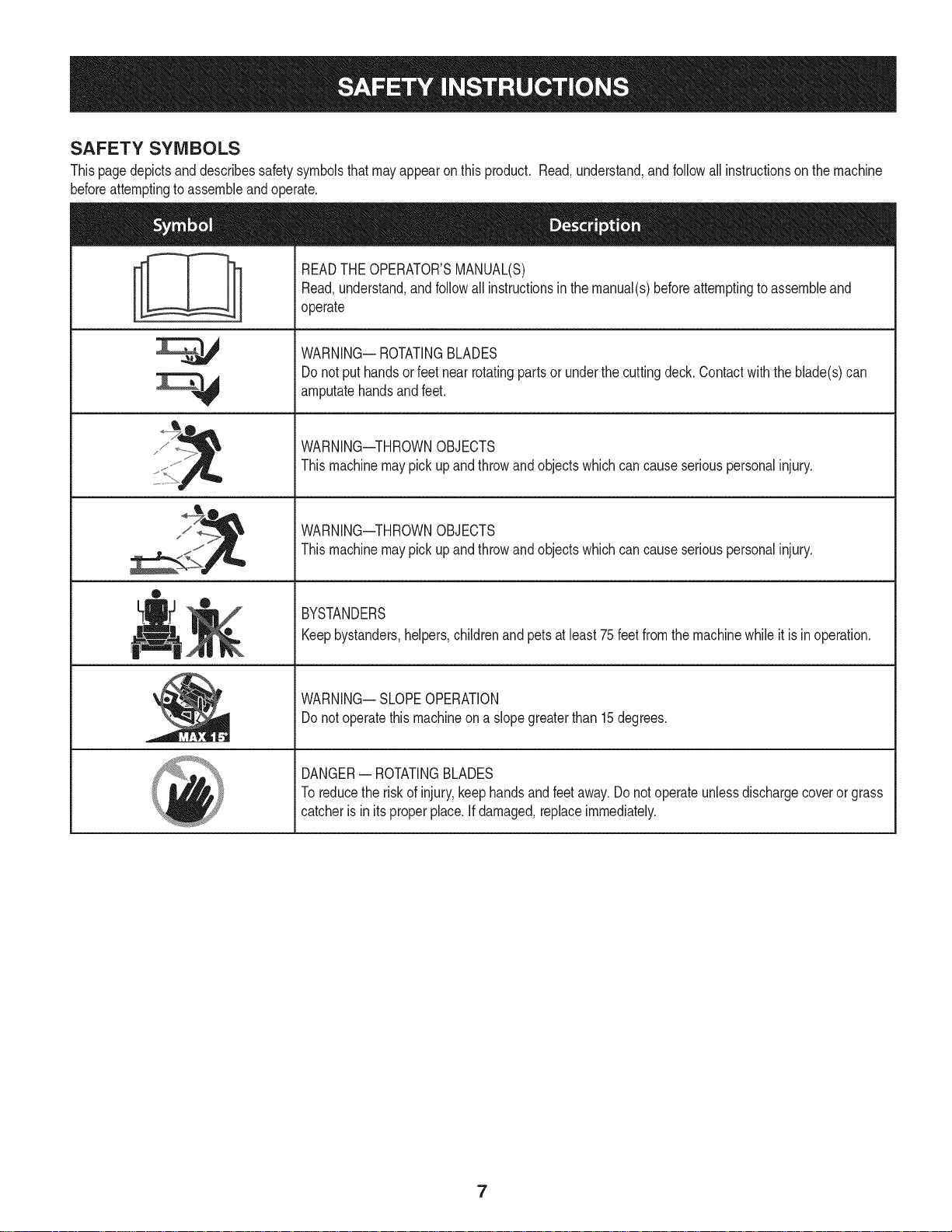
SAFETY SYMBOLS
Thispagedepictsanddescribessafetysymbolsthatmayappearonthisproduct.Read,understand,andfollowallinstructionson themachine
beforeattemptingto assembleandoperate.
READTHEOPERATOR'SMANUAL(S)
Read,understand,andfollowall instructionsinthemanual(s)beforeattemptingtoassembleand
operate
WARNING--ROTATINGBLADES
Donot puthandsor feetnearrotatingpartsor underthecuttingdeck.Contactwiththe blade(s)can
amputatehandsandfeet.
sJ / _
®
WARNING--THROWNOBJECTS
Thismachinemaypickupandthrowandobjectswhichcancauseseriouspersonalinjury.
WARNING--THROWNOBJECTS
Thismachinemaypickupandthrowandobjectswhichcancauseseriouspersonalinjury.
BYSTANDERS
Keepbystanders,helpers,childrenandpetsatleast75feetfromthemachinewhileit is inoperation.
WARNING--SLOPEOPERATION
Donot operatethismachineona slopegreaterthan15degrees.
DANGER-- ROTATINGBLADES
Toreducetheriskof injury,keephandsandfeetaway.Donotoperateunlessdischargecoveror grass
catcheris in itsproperplace.Ifdamaged,replaceimmediately.
7
15° Slope
15° Slope
X
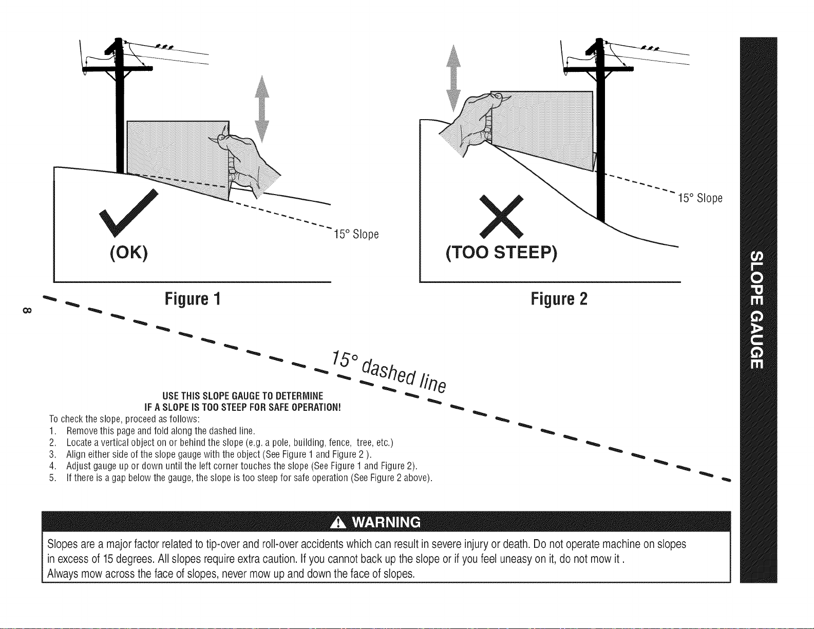
(OK)
'_. _ Figure1
(TOO STEEP)
Figure2
15°
dashedline
USETHISSLOPEGAUGETODETERMINE
IFA SLOPEISTOOSTEEPFORSAFEOPERATION!
Tochecktheslope,proceedasfollows:
1. Removethis pageandfoldalongthedashedline.
2. Locateaverticalobject onor behindthe slope(e.g.a pole, building,fence, tree,etc.)
3. Align eithersideoftheslopegaugewiththeobject(SeeFigure1 and Figure2).
4. Adjust gaugeupor down untilthe left cornertouchestheslope(SeeFigure1andFigure2).
5.
If thereis agap belowthe gauge,theslopeis too steepfor safeoperation(SeeFigure2 above).
Slopesare a majorfactor relatedtotip-over and roll-over accidents whichcan resultin severe injury or death. Do not operatemachineonslopes
in excess of 15degrees.All slopes require extra caution. Ifyou cannot backup the slope orif you feel uneasy on it, do not mow it.
Always mow across the face of slopes, never mow upand downthe face of slopes.
RiDiNG MOWER PREPARATION
Removethe uppercratingmaterialfromtheshippingpallet,andcut
anybandsor tiestrapssecuringtheridingmowertothepallet.
1. Usethelift handleto raisethedeckto itshighestposition.
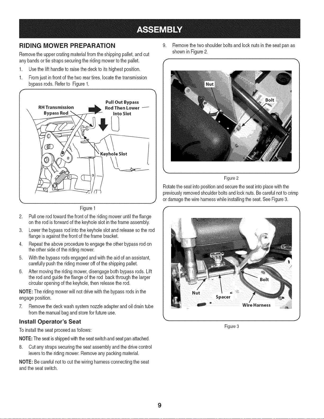
1. Fromjustin frontofthetwo reartires,locatethetransmission
bypassrods.Referto Figure1.
RH Transmission
BypassRod
Figure1
2. Pullonerodtowardthefrontof the ridingmoweruntilthe flange
ontherod is forwardofthe keyholeslotin theframeassembly.
3. Lowerthebypassrodintothekeyholeslotandreleasesothe rod
flangeis againstthefrontof theframebracket.
4. Repeattheaboveproceduretoengagetheotherbypassrodon
theother sideof the ridingmower.
5. Withthe bypassrodsengagedandwiththeaidof anassistant,
carefullypushtheridingmoweroffof theshippingpallet.
6. Aftermovingthe ridingmower,disengagebothbypassrods.Lift
therodandguidethe flangeof therod backthroughthelarger
circularopeningof the keyhole,then releasetherod.
NOTE:The ridingmowerwillnot drivewiththe bypassrodsinthe
engageposition.
7. Removethedeckwashsystemnozzleadapterandoildraintube
fromthemanualbagandstoreforfutureuse.
9. Removethe twoshoulderboltsandlocknutsin the seatpanas
showninFigure2.
Figure2
Rotatethe seatintopositionandsecuretheseatintoplacewiththe
previouslyremovedshoulderboltsandlocknuts.Becarefulnottocrimp
or damagethewireharnesswhileinstallingtheseat.SeeFigure3.
install Operator's Seat
Toinstallthe seatproceedasfollows:
NOTE:Theseatisshippedwiththeseatswitchandseatpanattached.
8. Cutanystrapssecuringtheseatassemblyandthedrivecontrol
leverstothe ridingmower.Removeanypackingmaterial.
NOTE:Becarefulnottocut thewiringharnessconnectingtheseat
andtheseatswitch.
Figure 3
9
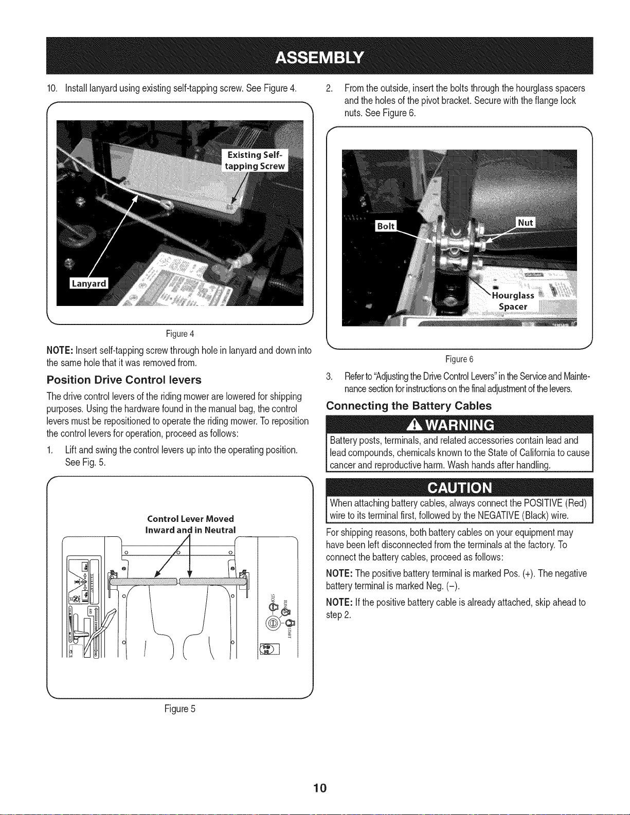
10. Installlanyardusingexistingself-tappingscrew.SeeFigure4. 2. Fromtheoutside,inserttheboltsthroughthehourglassspacers
andtheholesofthe pivotbracket.Securewith theflangelock
nuts.SeeFigure6.
Figure4
NOTE:Insertself-tappingscrewthroughholeinlanyardanddowninto
thesameholethatit was removedfrom.
Position Drive Control levers
Thedrivecontrolleversof the ridingmowerareloweredforshipping
purposes.Usingthehardwarefoundin themanualbag,the control
leversmustbe repositionedto operatethe ridingmower.To reposition
thecontrolleversfor operation,proceedasfollows:
1. Liftand swingthecontrolleversupintotheoperatingposition.
SeeFig.5.
3. Referto"AdjustingtheDriveControlLevers"intheServiceandMainte-
nancesectionforinstructionsonthefinaladjustmentofthelevers.
Connecting the Battery Cables
Batteryposts,terminals,and relatedaccessoriescontainleadand
leadcompounds,chemicalsknowntothe StateofCaliforniatocause
cancerand reproductiveharm.Washhandsafter handling.
Figure6
r
Control Lever Moved
inward and in Neutral
Figure5
Whenattachingbatterycables,alwaysconnectthePOSITIVE(Red)
wireto itsterminalfirst,followedbytheNEGATIVE(Black)wire.
Forshippingreasons,bothbatterycableson yourequipmentmay
havebeenleftdisconnectedfromthe terminalsatthefactory.To
connectthe batterycables,proceedasfollows:
NOTE:ThepositivebatteryterminalismarkedPos.(+).Thenegative
batteryterminalismarkedNeg.(-).
NOTE:If the positivebatterycableis alreadyattached,skipaheadto
step2.
J
10
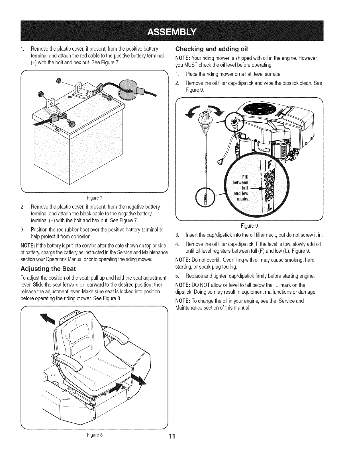
Removethe plasticcover,if present,fromthe positivebattery
terminaland attachthe redcableto thepositivebatteryterminal
(+)withtheboltandhexnut.See Figure7.
Figure7
2. Removethe plasticcover,if present,fromthe negativebattery
terminaland attachtheblackcane to thenegativebattery
terminal(-) withtheboltandhexnut.SeeFigure7.
3. Positionthe redrubberbootoverthepositivebatteryterminalto
helpprotectit fromcorrosion.
NOTE:Ifthe batteryisputintoserviceafterthedateshownontoporside
ofbattery,chargethebatteryasinstructedintheServiceandMaintenance
sectionyourOperator'sManualpriortooperatingtheridingmower.
Adjusting the Seat
Toadjustthe positionofthe seat,pullup andholdthe seatadjustment
lever.Slidetheseatforwardor rearwardtothe desiredposition;then
releasetheadjustmentlever.Makesureseatis lockedintoposition
beforeoperatingtheridingmower.SeeFigure8.
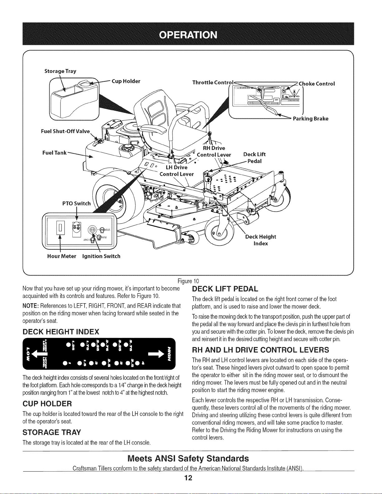
Checking and adding oil
NOTE:Yourridingmowerisshippedwithoil inthe engine.However,
youMUSTcheckthe oil levelbeforeoperating.
1. Placetheridingmoweron a flat,levelsurface.
2. Removethe oilfillercap/dipstickandwipe thedipstickclean.See
Figure9.
Figure9
3. Insertthecap/dipstickintothe oil fillerneck,butdo notscrewit in.
4. Removethe oilfillercap/dipstick.If thelevelislow,slowlyaddoil
untiloil levelregistersbetweenfull (F)andlow (L),Figure9.
NOTE:Do notoverfill.Overfillingwithoilmaycausesmoking,hard
starting,or sparkplugfouling.
5. Replaceandtightencap/dipstickfirmlybeforestartingengine.
NOTE:DO NOTallowoil levelto fall belowthe"L"markonthe
dipstick.Doingsomayresultinequipmentmalfunctionsor damage.
NOTE:Tochangetheoil inyourengine,seethe Serviceand
Maintenancesectionof thismanual.
Figure8 1 1
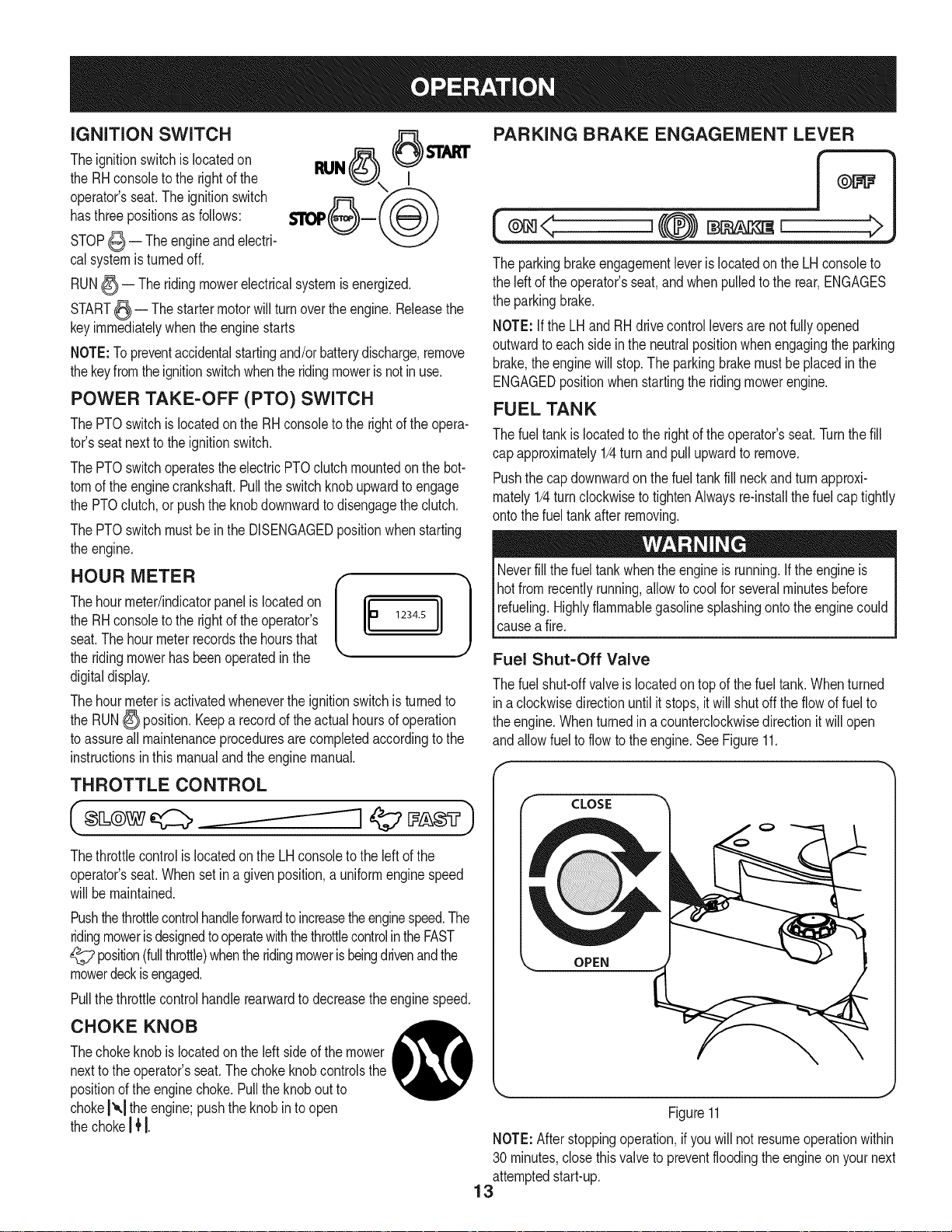
Storage Tray
FuelShut=Off Valve
PTOSwitch
!
Cup Holder
RH Drive
Control Lever Deck Lift
LHDrive
Control Lever
Deck Height
index
HourMeter ignition Switch
Figure10
Nowthat youhavesetup yourridingmower,it'simportanttobecome
acquaintedwith itscontrolsandfeatures.Referto Figure10.
NOTE:Referencesto LEFT,RIGHT,FRONT,andREARindicatethat
positionontheridingmowerwhenfacingforwardwhileseatedinthe
operator'sseat.
DECK HEIGHT INDEX
Thedeckheightindexconsistsofseveralholeslocatedonthefront!rightof
thefootplatform.Eachholecorrespondstoa1/4"changeinthedeckheight
positionrangingfrom1"atthelowestnotchto4"atthehighestnotch.
CUP HOLDER
Thecup holderis locatedtowardtherearofthe LHconsoleto the right
ofthe operator'sseat.
STORAGE TRAY
Thestoragetrayis locatedatthe rearofthe LHconsole.
DECK LiFT PEDAL
Thedecklift pedalislocatedon therightfrontcornerofthefoot
platform,andisusedto raiseand lowerthemowerdeck.
Toraisethemowingdecktothetransportposition,pushtheupperpartof
thepedalallthewayforwardandplacetheclevispininfurthestholefrom
youandsecurewiththecotterpin.Tolowerthedeck,removetheclevispin
andreinsertitinthedesiredcuttingheightandsecurewithcotterpin.
RH AND LH DRIVE CONTROL LEVERS
TheRHandLH controlleversarelocatedon eachsideofthe opera-
tor'sseat.Thesehingedleverspivotoutwardtoopenspacetopermit
theoperatortoeither sitin the ridingmowerseat,orto dismountthe
ridingmower.Theleversmustbefullyopenedoutand intheneutral
positionto starttheridingmowerengine.
Eachlevercontrolsthe respectiveRHorLHtransmission.Conse-
quently,theseleverscontrolallof themovementsofthe ridingmower.
Drivingand steeringutilizingthesecontrolleversisquitedifferentfrom
conventionalridingmowers,andwill takesomepracticetomaster.
Refertothe Drivingthe RidingMowerforinstructionsonusingthe
controllevers.
Meets ANSI Safety Standards
CraftsmanTillersconformtothe safetystandardofthe AmericanNationalStandardsInstitute(ANSI)
12
iGNiTiON SWITCH
Theignitionswitchis locatedon
theRHconsoleto therightofthe
operator'sseat.Theignitionswitch
hasthree positionsas follows:
PARKING BRAKE ENGAGEMENT LEVER
(®=< ,{@) =,, >
STOP_ -- Theengineandelectri-
calsystemisturnedoff.
RUN_-- Theridingmowerelectricalsystemisenergized.
START_ -- Thestartermotorwillturn overthe engine.Releasethe
keyimmediatelywhenthe enginestarts
NOTE:Topreventaccidentalstartingand/orbatterydischarge,remove
thekeyfromtheignitionswitchwhentheridingmowerisnotinuse.
POWER TAKE-OFF (PTO) SWITCH
ThePTOswitchislocatedonthe RHconsoletothe rightof theopera-
tot'sseatnexttotheignitionswitch.
ThePTOswitchoperatestheelectricPTOclutchmountedonthebot-
tomofthe enginecrankshaft.Pullthe switchknobupwardtoengage
thePTOclutch,or pushthe knobdownwardto disengagetheclutch.
ThePTOswitchmustbein the DISENGAGEDpositionwhenstarting
theengine.
Thehourmeter/indicatorpanelislocatedon
theRHconsoleto therightofthe operator's 1234.5
HOO.O.T.. '11
seat.The hourmeterrecordsthehoursthat
theridingmowerhas beenoperatedinthe
digitaldisplay.
Thehourmeteris activatedwhenevertheignitionswitchisturnedto
theRUN_ position.Keepa recordofthe actualhoursof operation
toassureall maintenanceproceduresarecompletedaccordingto the
instructionsin thismanualandtheenginemanual.
THROTTLE CONTROL
Theparkingbrakeengagementleverislocatedon the LHconsoleto
theleftof theoperator'sseat,andwhenpulledto the rear,ENGAGES
theparkingbrake.
NOTE:if theLHand RHdrivecontrolleversarenotfullyopened
outwardtoeach sideinthe neutralpositionwhenengagingtheparking
brake,theenginewill stop.Theparkingbrakemustbeplacedin the
ENGAGEDpositionwhenstartingtheridingmowerengine.
FUEL TANK
Thefueltankis locatedto therightofthe operator'sseat.Turnthefill
capapproximately1/4turnandpullupwardto remove.
Pushthecapdownwardon the fueltankfill neckandturnapproxi-
mately1/4turnclockwisetotightenAlwaysre-instalthefuel captightly
ontothefueltankafterremoving.
Neverfillthe fueltankwhentheengineis running,iftheengineis
hotfromrecentlyrunning,allowtocool forseveralminutesbefore
refueling.Highlyflammablegasolinesplashingontotheenginecould
_causea f re.
Fuel Shut=Off Valve
Thefuelshut-offvalveislocatedontop ofthe fueltank.Whenturned
ina clockwisedirectionuntilitstops,itwillshutoffthe flowoffuel to
theengine.Whenturnedinacounterclockwisedirectionitwillopen
andallowfuel toflowto theengine.SeeFigure11.
CLOSE
Thethrottlecontrolis locatedonthe LHconsoleto theleftof the
operator'sseat.Whensetina givenposition,a uniformenginespeed
willbemaintained.
Pushthethrottlecontrolhandleforwardto increasetheenginespeed.The
ridingmowerisdesignedtooperatewiththethrottlecontrolintheFAST
_;? position(fullthrottle)whentheridingmowerisbeingdrivenandthe
mowerdeckisengaged.
Pullthethrottlecontrolhandlerearwardto decreasetheenginespeed.
CHOKE KNOB
Thechokeknobislocatedonthe left sideof themower
nexttothe operator'sseat.Thechokeknobcontrolsthe
positionofthe enginechoke.Pullthe knobout to
chokeI'_,1theengine;pushtheknobintoopen
thechokeI JtI.
OPEN
Figure11
NOTE:Afterstoppingoperation,ifyouwill notresumeoperationwithin
30 minutes,closethisvalveto preventfloodingtheengineonyour next
attemptedstart-up.
13
SEAT ADJUSTMENT LEVER (NOT SHOWN)
Theseatadjustmentleverislocatedbelowthefront/leftof the seat.
Theleverallowsforadjustmentoftheforetoaft positionof the
operator'sseat.RefertotheServiceandMaintenancesectionfor
instructionsonadjustingthe seatposition.
TRANSMISSION BYPASS RODS (NOT SHOWN)
Thetransmissionbypassrods(oneforeachtheRHandLH transmis-
sion)are locatedbeneaththeframeplatform,just insideeachrear
wheel.SeeFigure1on page9.
Whenengaged,thetwo rodsopena bypasswithinthe hydrostatic
transmissions,whichallowsthe ridingmowertobe pushedshort
distancesbyhand. Refertothe Assembly sectionforinstructionson
usingthe bypassfeature.
Nevertowyourridingmower.Towingtheridingmowerwiththe rear
wheelsonthegroundmaycauseseveredamagetothetransmissions.
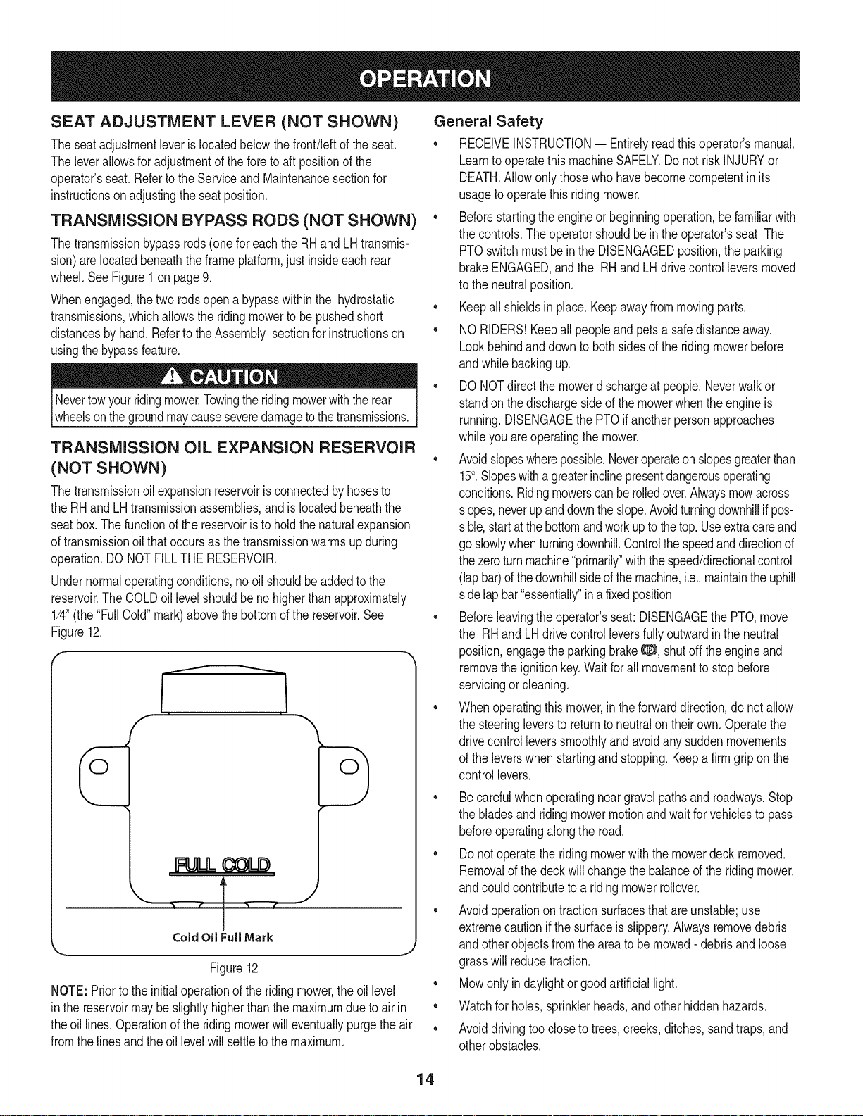
TRANSMISSION OIL EXPANSION RESERVOIR
(NOT SHOWN)
Thetransmissionoil expansionreservoirisconnectedbyhosesto
theRHandLHtransmissionassemblies,and islocatedbeneaththe
seatbox.Thefunctionofthe reservoiristoholdthenaturalexpansion
oftransmissionoilthatoccursas thetransmissionwarmsupduring
operation.DONOTFILLTHE RESERVOIR.
Undernormaloperatingconditions,nooil shouldbeaddedtothe
reservoir.The COLDoil levelshouldbe nohigherthanapproximately
1/4"(the"FullCold"mark)abovethebottomofthe reservoir.See
Figure12.
' • ..... • 3 ..... f
ColdOilFull Mark
Figure12
NOTE:Priorto theinitialoperationoftheridingmower,theoil level
inthe reservoirmaybeslightlyhigherthanthe maximumduetoair in
theoil lines.Operationofthe ridingmowerwilleventuallypurgetheair
fromthelines andtheoil levelwillsettletothe maximum.
General Safety
• RECEIVEINSTRUCTION-- Entirelyreadthisoperator'smanual.
Learnto operatethismachineSAFELY.Do notriskINJURYor
DEATH.Allowonlythosewhohavebecomecompetentin its
usageto operatethisridingmower.
• Beforestartingtheengineorbeginningoperation,befamiliarwith
thecontrols.Theoperatorshouldbein theoperator'sseat.The
PTOswitchmustbein theDISENGAGEDposition,theparking
brakeENGAGED,andthe RHand LHdrivecontrolleversmoved
tothe neutralposition.
• Keepallshieldsin place.Keepawayfrommovingparts.
• NORIDERS!Keepall peopleandpetsa safedistanceaway.
Lookbehindanddowntobothsidesoftheridingmowerbefore
andwhilebackingup.
• DONOTdirectthemowerdischargeatpeople.Neverwalkor
standonthedischargesideofthe mowerwhentheengineis
running.DISENGAGEthePTOifanotherpersonapproaches
whileyou areoperatingthemower.
• Avoidslopeswherepossible.Neveroperateonslopesgreaterthan
15°.Slopeswitha greaterinclinepresentdangerousoperating
conditions.Ridingmowerscanberolledover.Alwaysmowacross
slopes,neverupanddowntheslope.Avoidturningdownhillif pos-
sible,startat thebottomandworkuptothetop.Useextracareand
go slowlywhenturningdownhill.Controlthespeedanddirectionof
thezeroturnmachine"primarily"withthespeed/directionalcontrol
(lapbar)ofthedownhillsideofthemachine,i.e.,maintaintheuphill
sidelapbar"essentially"in afixedposition.
• Beforeleavingtheoperator'sseat:DISENGAGEthePTO,move
the RHand LHdrivecontrolleversfullyoutwardinthe neutral
position,engagetheparkingbrake0, shutoff the engineand
removetheignitionkey.Waitfor all movementto stopbefore
servicingorcleaning.
• Whenoperatingthismower,inthe forwarddirection,donotallow
thesteeringleversto returnto neutralontheirown.Operatethe
drivecontrolleverssmoothlyandavoidanysuddenmovements
ofthe leverswhenstartingandstopping.Keepafirmgripon the
controllevers.
• Becarefulwhenoperatingneargravelpathsandroadways.Stop
thebladesandridingmowermotionandwaitforvehiclesto pass
beforeoperatingalongtheroad.
• Donotoperatetheridingmowerwiththemowerdeckremoved.
Removalof thedeckwillchangethe balanced theridingmower,
andcouldcontributetoa ridingmowerrollover.
Avoidoperationontractionsurfacesthatare unstable;use
extremecautionif thesurfaceis slippery.Alwaysremovedebris
andotherobjectsfromtheareato bemowed- debrisandloose
grasswillreducetraction.
• Mowonlyindaylightorgoodartificiallight.
• Watchfor holes,sprinklerheads,andotherhiddenhazards.
• Avoiddrivingtoocloseto trees,creeks,ditches,sandtraps,and
otherobstacles.
14
• Slowdownbeforeturningandcometoa completestopbefore
anyzeroturnmaneuver.
• If youhit a solidobjectwhilemowing,DISENGAGEthePTO,
placethe steeringleversintheneutral,opened-outposition,
movethethrottleto slowq?::>,settheparkingbrake8, shutoff
theengine,andtakethekeyfromthe ignitionswitch.Inspectfor
damage.Repairthedamage.Makesurethe bladesarein good
conditionandthatthebladeboltsare tightbeforerestartingthe
engine.
• Donot stoptheridingmowerorparktheridingmowerover
combustiblematerialssuchas drygrass,leaves,debris,etc.
• Keepthemowerandespeciallytheengineandhydrauliccompo-
nentscleanandfree ofgrease,grass,and leavesto reducethe
chanceoffire andpermitpropercooling.
• Donotfillthe fueltankwhen theengineis runningorwhilethe
engineishot.Allowtheengineseveralminutestocool before
refueling.Tightenthefuelcapsecurely.
BEFORE OPERATING YOUR RIDING MOWER
1. Beforeyouoperatetheridingmower,studythismanualcarefully
tofamiliarizeyourselfwiththe operationofalltheinstrumentsand
controls.Ithasbeenpreparedtohelpyouoperateandmaintain
yourridingmowerefficiently.
2. Fillthefueltankwithonlyclean,fresh,unleadedgasolinewitha
pumpstickeroctaneratingof87or higher.Whenthe fuelreaches
oneinchfromthe topof thetank,stop.DO NOTOVERFILL.
Spacemustbeleftforexpansion.
3. Checktheengineoil level.Pullouttheoildipstick,wipeitoffand
reinsertit. Pullitout againand readtheoillevel.Ifit is belowthe
operatingrange,addoil throughthefilltube usingafunnelto
bringitupto thetop ofthe operatingrange.
4. Checkthetireinflationpressures-8-10psifor thereartires,
20-25psifronttires.
NOTE:Newtiresareoverinflatedinordertoproperlyseatthebeadto
therim.
5. Checkthatall nuts,boltsandscrewsaretight.
6. Checkthetensionofthe deckdrivebeltsas instructedin the
ServiceandMaintenancesection.
7. Checkif deckislevel.Whencorrectlyadjustedthemowerdeck
shouldbelevelsideto side,andthefrontof thedeckshouldbe
approximately1/4"lowerthantherearofdeck.Ifdeckneedstobe
leveled,refertotheServiceand Maintenancesection.
8. Lubricateall pivotpointslistedin theServiceandMaintenance
section.
9. Adjusttheseatforoperator'smaximumcomfort,visibilityandfor
maintainingcompletecontrolofthe ridingmower.
SAFETY INTERLOCK SYSTEM
• This ridingmowerisequippedwitha safetyinterlocksystemfor
theprotectionofthe operator.Iftheinterlocksystemshouldever
malfunction,do not operatetheridingmower.Call1-800-659-
5917toscheduleservicefromSearsParts& Repair.
• Thesafetyinterlocksystempreventstheenginefromcranking
or startingunlessthe RHandLH drivecontrolleversaremoved
fullyoutwardtoeachsideinthe neutralposition,theparking
brakeis ENGAGED,andthe PTOis DISENGAGED.
• Toavoidsuddenmovementwhendisengagingtheparkingbrake,
thesafetyinterlocksystemwillshutoff theengineif the RHand/
or LHdrivecontrolleversaremovedtoa positionotherthan
thefullyout inthe neutralpositionwhenthe parkingbrakeis
engaged.
• Thesafetyinterlocksystemwillshutoff theengineif theoperator
leavestheseatbeforeengagingtheparkingbrake.
• Thesafetyinterlocksystemwillshutoff theengineif theoperator
leavestheseatwiththe PTOengaged,regardlessofwhetherthe
parkingbrakeisengaged.
NOTE:The PTOswitchmustbemovedtothe DISENGAGEDposition
to restarttheengine.
• Thesafetyinterlocksystemwillshutoff thePTOandthemower
bladeswillstopifbothdrivecontrolleversaremovedintothe
reverseposition.ThePTOwill re-engagewhenoneorbothof the
leversare movedbacktoeithertheneutralor forwardposition.
15
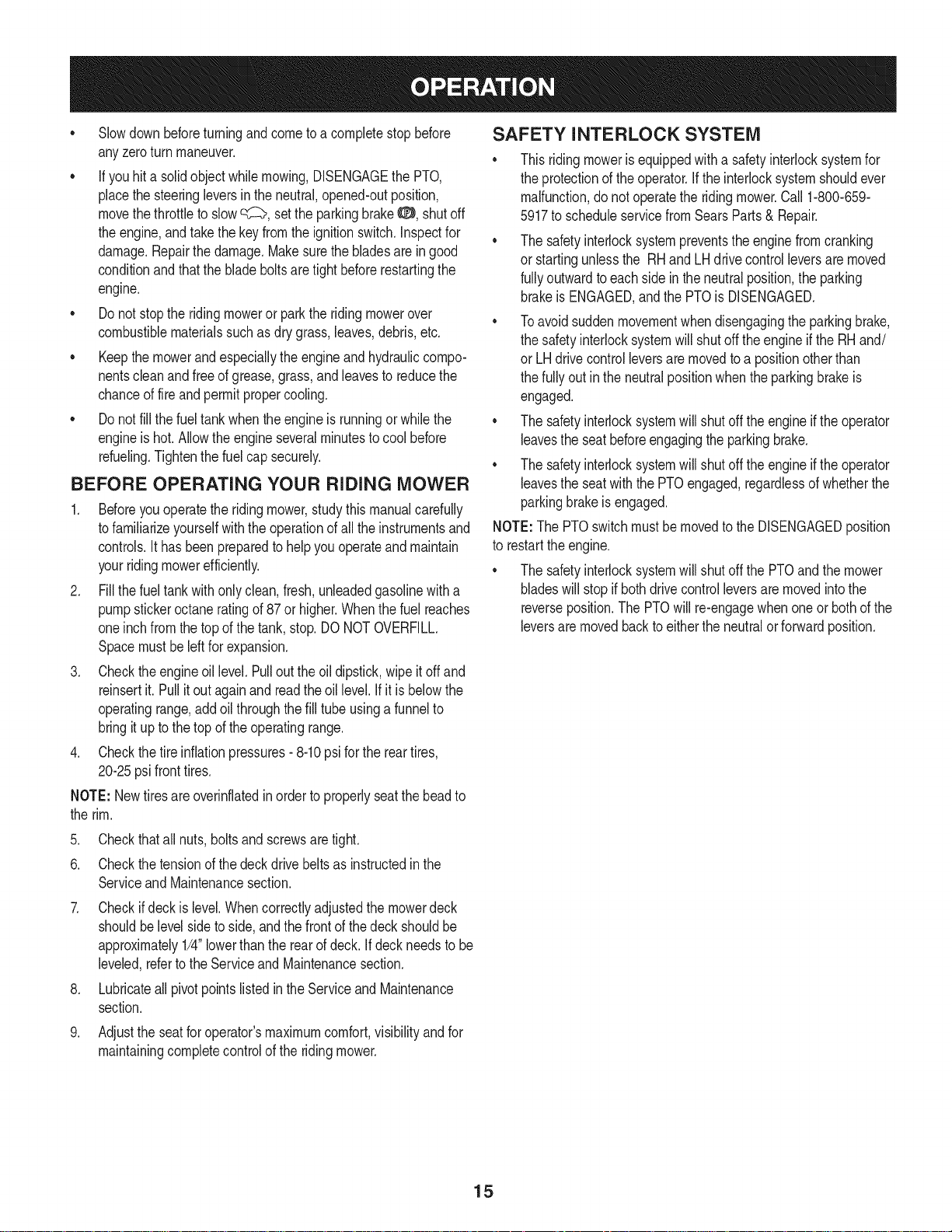
STARTING THE ENGINE
Thisridingmowerisequippedwitha safetyinterlocksystem
designedfortheprotectionofthe operator.Donotoperatetheriding
mowerifany partof theinterlocksystemis malfunctioning.Periodi-
_cay checkthefunctonsofthe nterocksystemforproperoperaton.
Forpersonalsafety,theoperatormustbe sittinginthe ridingmower
seatwhenstartingtheengine.
.
Openthefuel shut-offvalve.
2.
Operatormustbesittingin the tractorseatwith bothdrivecontrol
leversfullyoutwardto eachsideinthe neutral/startposition.See
Figure13.
LHControlLever
Outin !eutral
Parking Break
Engaged
RHControl Lever
Out in Neutral
7. Turnthe ignitionkeyclockwisetotheSTART_ positionand
releaseitassoonasthe enginestarts;however,do notcrankthe
enginecontinuouslyformorethan 10secondsata time. Ifthe
enginedoesnot startwithinthis time,turnthe keytoSTOP
andwaitatleast30 secondstoallowtheengine'sstartermotor
tocool.Tryagainafterwaiting.Ifaftera fewattemptstheengine
failsto start,do not keeptryingto startitwiththe chokeclosedas
this willcausefloodingandmakestartingmoredifficult.
8. Oncetheenginewarmsup, pushthechokeknobdownintothe
OFFI{ !position.
Cold Weather Starting
Whenstartingtheengineat temperaturesnearor belowfreezing,
ensurethecorrectviscositymotoroil is usedinthe engineandthe
batteryis fullycharged.Starttheengineas follows:
1. Besurethe batteryisingoodcondition.Also,awarmbatteryhas
muchmorestartingcapacitythana coldbattery.
2. Usefreshwintergradefuel.Wintergradegasolinehashigher
volatilitytoimprovestarting.Do notuse gasolineleftoverfrom
summer.
3. Followthepreviousinstructionfor Startingthe Engine.
Using Jumper Cables To Start Engine
CHOKE Position
Figure13
3. EngagetheparkingbrakeO.
4. MakecertainthePTOswitchisinthe DISENGAGED(down)
position.
5. Pullthechokeknobup intotheCHOKE!'_.1position.
NOTE:Ifthe engineiswarmedup, itmaynotbe necessarytochoke
theengine.
6. Pushthe throttlecontroltothe FAST_ (full throttle)position.
Batteriescontainsulfuricacidandproduceexplosivegasses.Make
certaintheareais wellventilated,wearglovesandeyeprotection,
land avod sparksorfamesnearthe battery.
Ifthe batterychargeisnotsufficientto cranktheengine,rechargethe
battery.If a batterychargeris unavailableandtheridingmowermust
be started,theaidof a boosterbatterywillbe necessary.Connectthe
boosterbatteryas follows:
1. Connecttheendof one cableto thedisabledridingmowerbat-
J
tery'spositiveterminal;thenconnecttheotherendof thatcableto
theboosterbattery'spositiveterminal.
2. Connectoneendof the othercabletothe boosterbattery's
negativeterminal;thenconnecttheotherendofthatcableto
the frameofthe disabledridingmower,asfar fromthebatteryas
possible.
3. Startthedisabledridingmowerfollowingthenormalstarting
instructionspreviouslyprovided;thendisconnectthejumper
cablesintheexactreverseorderoftheirconnection.
4. Havetheridingmower'selectricalsystemcheckedandrepaired
assoonas possibletoeliminatethe needforjumpstarting.
16
Stopping the Engine
1. PushthePTOswitchdownintotheDISENGAGEDposition.
2. MovetheRHandLH drivecontrolleversoutwardtotheneutral
position.
3. EngagetheparkingbrakeO.
4. MovethethrottlecontroltomidwaybetweentheSLOW_ and
FAST_ positions.
5. Turntheignitionkeyto the STOP6 positionand removethekey
fromtheignitionswitch.
NOTE:Alwaysremovethekeyfromthe ignitionswitchto preventacci-
dentalstartingor batterydischargeiftheequipmentis Idt unattended.
PRACTICE OPERATION (INITIAL USE)
Operatinga zero-turnridingmoweris notlikeoperatinga conventional
typeridingmower.Becausea zeroturnridingmowerismoremaneuver-
able,gettingusedtooperatingthecontrolleverstakessomepractice.
Westronglyrecommendthatyou locatea reasonablylarge,leveland
open"practicearea"wheretherearenoobstructions,pedestrians,or
animals.Youshouldpracticeoperatingtheridingmowerfora minimum
of30 minutes.
Carefullymove-- or haveanexperiencedusermove-- theriding
mowertothe practicearea.Whenperformingthepracticesession,
thePTOshouldnotbeengaged.Whilepracticing,operatetheriding
moweratapproximately1/2to3/4throttleandat lessthanfull speedin
bothforwardandreverse.
Useprotectiveequipmentforeyes,hands,hearing,feet,legs,head
andotherareasofthe bodyif needed-- safetyeyeglasses,gloves,
earplugs,boots,hats,etc.
HearingProtectionisrequiredforalloperatorexposureexceeding
two(2) hours.
Carefullypracticemaneuveringtheridingmowerusingtheinstructions
in thefollowingsection"DrivingtheRidingmower."Practiceuntilyou
areconfidentthatyoucansafelyoperatetheridingmower.
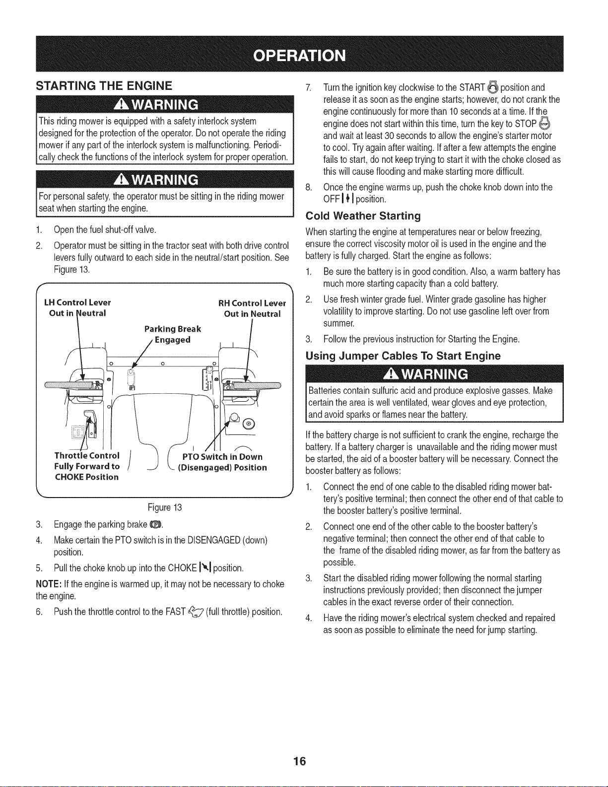
DRIVING THE RIDING MOWER
Avoidsuddenstarts,excessivespeedandsuddenstops.
1. Adjusttheoperator'sseattothemostcomfortablepositionthat
allowsyouto operatethecontrols.Seeseatadjustmentinthe
Assemblysection.
2. ReleasetheparkingbrakeO.
3. Movethe RHand LHdrivecontrolleversinwardin theneutral
position.RefertoFigure14.
ControlLeverMoved
inwardand in Neutral
o
/
Figure14
NOTE:If thecontrolleversarenotevenin theneutralposition,refer
to ServiceandMaintenanceforinstructionstoadjustthe leverssothat
theyareeven.
4. Movethethrottlecontrolleverforwardto theFAST_ (full
throttle)position.
NOTE:Althoughtheridingmower'sengineisdesignedto runatfull
throttle,whenperformingapracticesessiontheridingmowermustbe
operatedatlessthanfullthrottle.Thisonlyappliestopractice.
17
usingyourhands.
Todrive theridingmower,firmlygrasptherespectivedrive control
leverswithyourrightandleft handsandproceedtodriveas
describedinthefollowingDrivingtheTractorForwardsection.
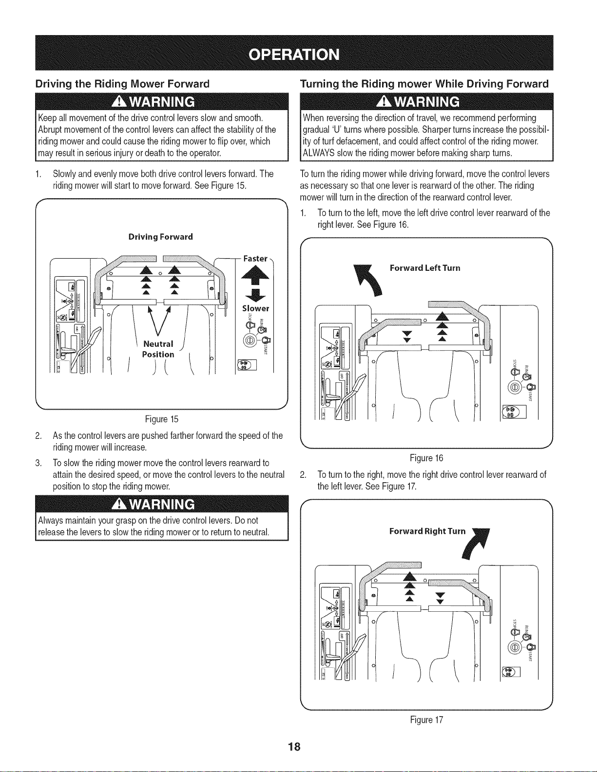
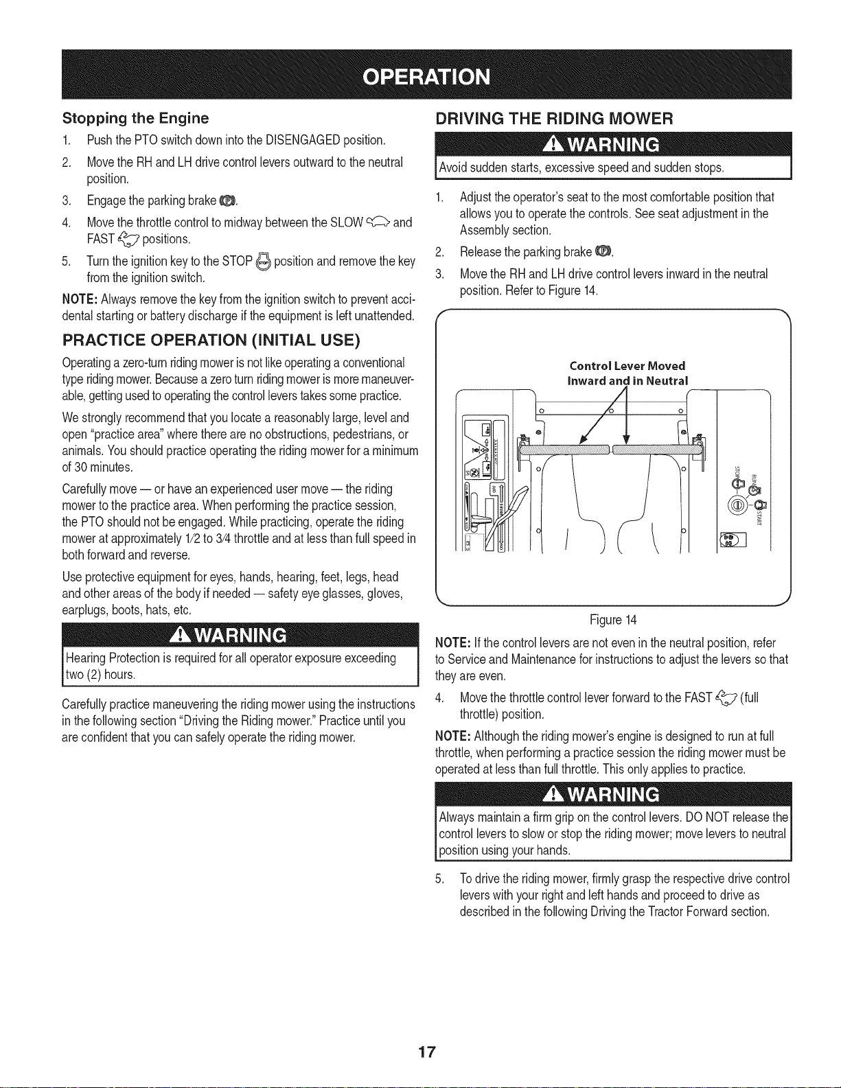
Driving the Riding Mower Forward
Turning the Riding mower While Driving Forward
Keepall movementofthe drivecontrolleversslowandsmooth.
Abruptmovementof thecontrolleverscan affectthestabilityof the
ridingmowerandcouldcausethe ridingmowertoflipover,which
mayresultin seriousinjuryordeathtothe operator.
1. Slowlyandevenlymovebothdrivecontrolleversforward.The
ridingmowerwillstart tomoveforward.SeeFigure15.
Driving Forward
- Faster -
o
_. ,A A _'-_/
_,t ,,L A t,,I I I
t A ,,, h
S, w:r
¢
J/A
\ Neutral ) 1
/.o?,.,i°i ,
Whenreversingthe directionoftravel,werecommendperforming
gradual'U turnswherepossible.Sharperturnsincreasethepossibil-
ity ofturfdefacement,andcouldaffectcontrolof the ridingmower.
IALWAYSsow therdngmowerbeforemakng sharpturns.
Toturn theridingmowerwhiledrivingforward,movethecontrollevers
asnecessaryso thatone leveris rearwardoftheother.The riding
mowerwillturn inthedirectionof therearwardcontrollever.
1. Toturnto theleft, movetheleftdrivecontrolleverrearwardofthe
rightlever.SeeFigure16.
Forward Left Turn
o
Figure15
.
Asthecontrolleversarepushedfartherforwardthespeedofthe
ridingmowerwillincrease.
.
Toslowthe ridingmowermovethecontrolleversrearwardto
attainthedesiredspeed,ormovethecontrolleverstothe neutral
positiontostopthe ridingmower.
Alwaysmaintainyourgraspon the drivecontrollevers.Donot
releasetheleverstoslowthe ridingmowerorto returnto neutral.
Figure16
.
Toturn tothe right,movetherightdrivecontrolleverrearwardof
theleft lever.SeeFigure17.
Forward Right Tur_
0 '
J
_ J
Figure17
18
NOTE:The greaterthefore-to-aftdistancebetweenthetwolevers,the
sharpertheridingmowerwillturn.
3. Toexecutea "zeroturn,"movetheturnsidedrivecontrolleverto
theneutralposition,whilemovingtheothercontrolleverforward.
NOTE:Makinga"zeroturn"on grasswillgreatlyincreasethepotential
fordefacementof theturf.
Driving the Riding mower in Reverse
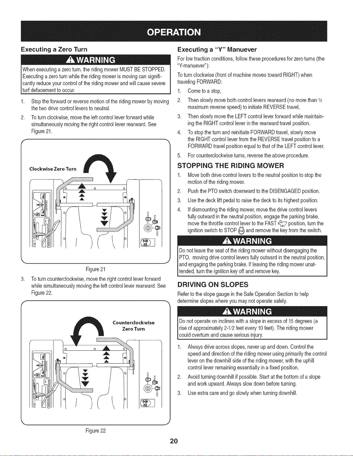
Turning While Driving Rearward
Toturn theridingmowerwhiledrivingrearward,movethe control
leversas necessarysothatoneleverisforwardofthe other.Theriding
mowerwillturn inthedirectionoftheforwardcontrollever.
1. Toturnto theleftwhiletravelingin reverse,movetheleftdrive
controlleverforwardoftheright lever.See Figure19.
Alwayslookbehindanddownonbothsidesoftheridingmowerbefore
backingup.Alwayslookbehindwhiletravelinginthereversedirection.
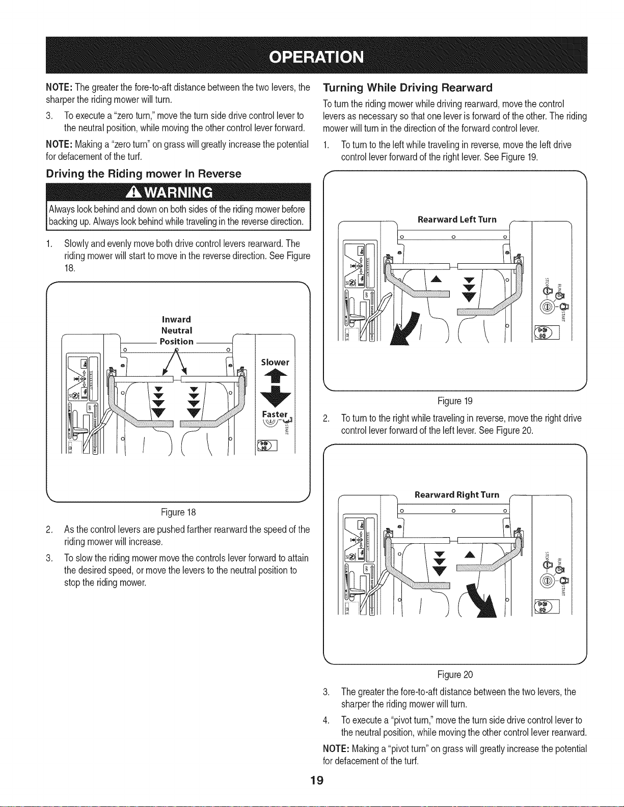
1. Slowlyandevenlymovebothdrive controlleversrearward.The
ridingmowerwillstartto movein the reversedirection.SeeFigure
18.
inward
o
Neutral
_ Position o_
Slower
Faster
RearwardLeftTurn
o
Figure19
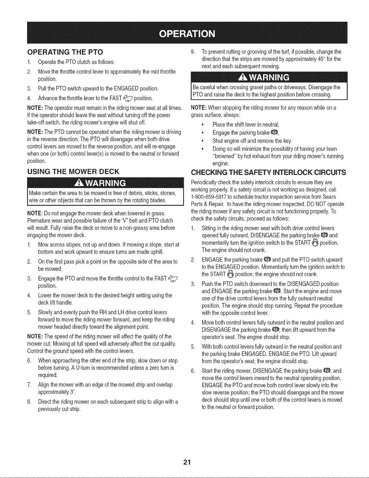
2. Toturntothe rightwhiletravelingin reverse,movetherightdrive
controlleverforwardoftheleft lever.SeeFigure20.
Figure18
.
Asthecontrolleversarepushedfartherrearwardthespeedofthe
ridingmowerwillincrease.
.
Toslowthe ridingmowermovethecontrolsleverforwardto attain
thedesiredspeed,or movetheleversto theneutralpositionto
stoptheridingmower.
m
II ,.-,'qII
J
Figure20
3. Thegreaterthefore-to-aftdistancebetweenthetwolevers,the
sharpertheridingmowerwillturn.
4. Toexecutea "pivotturn,"movetheturnsidedrivecontrolleverto
theneutralposition,whilemovingtheothercontrolleverrearward.
NOTE:Makinga"pivotturn"on grasswill greatlyincreasethe potential
fordefacementof theturf.
19
Executing a Zero Turn
Whenexecutinga zeroturn,the ridingmowerMUSTBESTOPPED.
Executinga zeroturnwhiletheridingmoweris movingcansignifi-
Icantlyreduceyourcontrolofthe ridingmowerandwillcausesevere
[turfdefacementto occur.
1. Stopthe forwardor reversemotionoftheridingmowerbymoving
thetwo drivecontrolleverstoneutral.
2. Toturnclockwise,movetheleftcontrolleverforwardwhile
simultaneouslymovingthe rightcontrolleverrearward.See
Figure21.
Clockwise Zero Turn
Executing a "Y" Manuever
Forlowtractionconditions,followtheseproceduresfor zeroturns(the
"Y-manuever"):
Toturn clockwise(frontof machinemovestowardRIGHT)when
travelingFORWARD:
1. Cometoa stop,
2. Thenslowlymovebothcontrolleversrearward(nomorethan 1/2
maximumreversespeed)to initiateREVERSEtravel,
3. Thenslowlymovethe LEFTcontrolleverforwardwhilemaintain-
ingthe RIGHTcontrolleverinthe rearwardtravelposition.
4. TostoptheturnandreinitiateFORWARDtravel,slowlymove
the RIGHTcontrolleverfromtheREVERSEtravelpositionto a
FORWARDtravelpositionequalto thatofthe LEFTcontrollever.
5. Forcounterclockwiseturns, reversetheaboveprocedure.
STOPPING THE RIDING MOWER
1. Movebothdrivecontrolleverstothe neutralpositionto stopthe
motionofthe ridingmower.
2. PushthePTOswitchdownwardtotheDISENGAGEDposition.
3. Usethedecklift pedalto raisethedecktoitshighestposition.
4. Ifdismountingthe ridingmower,movethe drivecontrollevers
fullyoutwardin theneutralposition,engagetheparkingbrake,
movethethrottlecontrolleverto theFAST_ position,turnthe
ignitionswitchtoSTOP_ and removethekeyfromtheswitch.
Figure21
.
Toturncounterclockwise,movethe rightcontrolleverforward
whilesimultaneouslymovingtheleftcontrolleverrearward.See
Figure22.
Counterclockwise
Zero Turn
o
_uL
I 1 _'-III
((¢))-@
/
Donot leavetheseatofthe ridingmowerwithoutdisengagingthe
PTO, movingdrivecontrolleversfullyoutwardinthe neutralposition,
land engagingthe parkingbrake.Ifleavingtheridingmowerunat-
ltended,turnthe ignitionkeyoffand removekey.
DRIVING ON SLOPES
Refertothe slopegaugeinthe SafeOperationSectiontohelp
determineslopeswhereyou maynotoperatesafely.
Donot operateoninclineswitha slope inexcessof 15degrees(a
riseof approximately2-1/2feetevery 10feet).Theridingmower
couldoverturnandcauseseriousinjury.
1. Alwaysdriveacrossslopes,neverup anddown.Controlthe
speedanddirectionof theridingmowerusingprimarilythecontrol
leveron thedownhillsideofthe ridingmower,withthe uphill
controlleverremainingessentiallyina fixedposition.
2. Avoidturningdownhillif possible.Startatthebottomofa slope
andworkupward.Alwaysslowdown beforeturning.
3. Useextracareandgo slowlywhenturningdownhill.
Figure22
2O
OPERATING THE PTO
1. OperatethePTOclutchasfollows:
2. Movethethrottlecontrolleverto approximatelythemidthrottle
position.
3. PullthePTOswitchupwardtotheENGAGEDposition.
4. Advancethethrottleleverto theFAST_ position.
NOTE:The operatormustremaininthe ridingmowerseatatall times.
If theoperatorshouldleavetheseatwithoutturningoffthe power
take-offswitch,the ridingmower'senginewill shutoff.
NOTE:The PTOcannotbeoperatedwhenthe ridingmowerisdriving
in thereversedirection.ThePTOwilldisengagewhenbothdrive
controlleversaremovedtothe reverseposition,and will re-engage
whenone(or both)controllever(s)ismovedto theneutralor forward
position.
USING THE MOWER DECK
Makecertaintheareato be mowedisfree ofdebris,sticks,stones,
wireor otherobjectsthatcan bethrownbythe rotatingblades.
NOTE:Do notengagethe mowerdeckwhenloweredingrass.
Prematurewearandpossiblefailureofthe 'V" beltandPTOclutch
willresult.Fullyraisethe deckor moveto anon-grassyareabefore
engagingthemowerdeck.
1. Mowacrossslopes,notup anddown.Ifmowinga slope,startat
bottomandworkupwardtoensureturnsare madeuphill.
2. Onthefirst passpicka pointon theoppositesideofthe areato
bemowed.
3. Engagethe PTOandmovethethrottlecontrolto the FAST
position.
4. Lowerthemowerdecktothe desiredheightsettingusingthe
decklift handle.
5. Slowlyandevenlypushthe RHandLHdrivecontrollevers
forwardtomovethe ridingmowerforward,andkeepthe riding
mowerheadeddirectlytowardthealignmentpoint.
NOTE:The speedof theridingmowerwill affectthequalityof the
mowercut.Mowingatfullspeedwilladverselyaffectthecut quality.
Controlthegroundspeedwiththecontrollevers.
6. Whenapproachingtheotherendofthe strip,slowdownor stop
beforeturning.AU-turnis recommendedunlessazeroturnis
required.
7. Alignthemowerwithanedgeof themowedstripandoverlap
approximately3".
8. Directtheridingmoweroneachsubsequentstriptoalignwitha
previouslycut strip.
9. Topreventruttingorgroovingoftheturf,ifpossible,changethe
directionthatthestripsaremowedbyapproximately450forthe
nextandeachsubsequentmowing.
Becarefulwhencrossinggravelpathsordriveways.Disengagethe
PTOandraisethedeckto thehighestpositionbeforecrossing.
NOTE:Whenstoppingtheridingmowerforanyreasonwhileon a
grasssurface,always:
• Placetheshiftleverinneutral,
• Engagetheparkingbrake8,
• Shutengineoffandremovethekey.
• Doingsowillminimizethepossibilityofhavingyourlawn
"browned"byhotexhaustfromyour ridingmower'srunning
engine.
CHECKING THE SAFETY INTERLOCK CIRCUITS
Periodicallycheckthe safetyinterlockcircuitstoensuretheyare
workingproperly.Ifa safetycircuitis notworkingas designed,call
1-800-659-5917to scheduletractorinspectionservicefromSears
Parts& Repair.to havethe ridingmowerinspected.DONOToperate
theridingmowerif anysafetycircuitisnot functioningproperly.To
checkthe safetycircuits,proceedasfollows:
1. Sittinginthe ridingmowerseatwithbothdrivecontrollevers
openedfullyoutward,DISENGAGEthe parkingbrake_ and
momentarilyturnthe ignitionswitchto theSTART_ position.
Theengineshouldnotcrank.
2. ENGAGEtheparkingbrake0 and pullthe PTOswitchupward
tothe ENGAGEDposition.Momentarilyturntheignitionswitchto
theSTART_ position;theengineshouldnotcrank.
3. Pushthe PTOswitchdownwardto theDISENGAGEDposition
and ENGAGEthe parkingbrake0. Starttheengineand move
oneof thedrivecontrolleversfromthe fullyoutwardneutral
position.The engineshouldstoprunning.Repeatthe procedure
withtheoppositecontrollever.
4. Movebothcontrolleversfullyoutwardinthe neutralpositionand
DISENGAGEtheparkingbrake0; thenliftupwardfromthe
operator'sseat.Theengineshouldstop.
5. Withbothcontrolleversfullyoutwardinthe neutralpositionand
theparkingbrakeENGAGED,ENGAGEthe PTO.Liftupward
fromtheoperator'sseat;theengineshouldstop.
6. Starttheridingmower,DISENGAGEtheparkingbrake0, and
movethecontrolleversinwardtothe neutraloperatingposition.
ENGAGEthe PTOandmovebothcontrolleverslowlyintothe
slowreverseposition;thePTOshoulddisengageandthe mower
deckshouldstopuntiloneor bothof thecontrolleversis moved
tothe neutralorforwardposition.
21
MAINTENANCE SCHEDULE
Beforeperformingany typeofmaintenance/service,disengageall
controlsandstopthe engine.Waituntilall movingpartshavecome
toa completestop.Disconnectsparkplugwireandgroundit against
theengineto preventunintendedstarting.Alwayswearsafetyglasses
duringoperationorwhile performinganyadjustmentsor repairs.
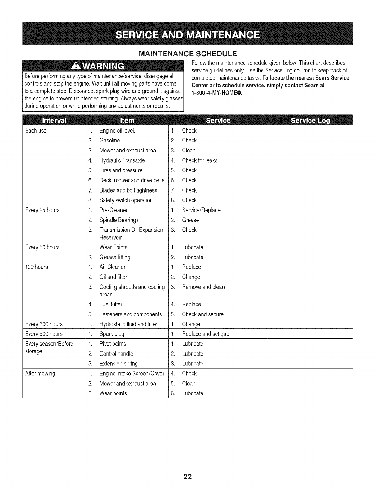
Followthemaintenanceschedulegivenbelow.Thischartdescribes
serviceguidelinesonly.UsetheServiceLogcolumnto keeptrackof
completedmaintenancetasks.Tolocatethe nearest Sears Service
Centeror to scheduleservice,simplycontactSearsat
1-800-4-MY-HOME®.
Eachuse
Every25 hours
Every50 hours
100hours
Every300 hours
Every500 hours
Everyseason/Before
storage
Aftermowing
1. Engineoillevel.
2. Gasoline
3. Mowerand exhaustarea
4. HydraulicTransaxle
5. Tiresand pressure
6. Deck,moweranddrivebelts
7. Bladesandbolttightness
8. Safetyswitchoperation
1. Pre-Cleaner
2. SpindleBearings
3. TransmissionOilExpansion
Reservoir
1. WearPoints
2. Greasefitting
1. AirCleaner
2. Oilandfilter
3. Coolingshroudsandcooling
areas
4. FuelFilter
5. Fastenersand components
1. Hydrostaticfluidandfilter
1. Sparkplug
1. Pivotpoints
2. Controlhandle
3. Extensionspring
1. EngineIntakeScreen/Cover
2. Mowerand exhaustarea
3. Wearpoints
1. Check
2. Check
3. Clean
4. Checkfor leaks
5. Check
6. Check
7. Check
8. Check
1. Service/Replace
2. Grease
3. Check
1. Lubricate
2. Lubricate
1. Replace
2. Change
3. Removeandclean
4. Replace
5. Checkandsecure
1. Change
1. Replaceandsetgap
1. Lubricate
2. Lubricate
3. Lubricate
4. Check
5. Clean
6. Lubricate
22

OIL CHART
Applya fewdropsofSAEengineoil,grease,or usea spraylubricant.Applythe oil tobothsidesofpivotpoints.Wipeoffanyexcess.Startengine
andoperatemowerbrieflytoinsurethatoil spreadsevenly.
Number of Oil Points Description
DALLY
4 DeckSuspensionPivots
4 HeightAdjustmentTurnbuckleClevisPin
2 HeightAdjustmentHandlePivots
2 HeightAdjustmentStopPivots
2 DeckLiftLinkagePivots
2 TransportHandlePivots
1 TransportHandlePin
2 DeckFrameUp-and-DownPivots
WEEKLY
1 SeatHinge
2 SteeringLeverLinkageRodEndBearings
2 LeverReturnAssemblyRodEndBearings
2 PumpControlLeverPivots
2 GrassCollectionSystemLidHinges(IfMoweris soequipped)
LUBRICATION CHART
Usea grease-gunfilledwith NO.2 MultipurposeLithiumBaseGrease
Numberof GreaseFittings Description
EVERY25 HOURS
3 BladeSpindleBearings
WEEKLY
2 FrontCasterWheels
2 FrontCasterWheelSpindles
2 MowerDeckBallWheels
Numberof Grease Points Description
WEEKLY
4 MowingDeckPivots
2 DeckTake-UpIdlerPivots
Hydrostatic Fluid: Rimula15W40recommended.
Spindle Lubricant:UseonlyShellAlvaniaRL2grease.Thisgreaseisanamber-coloredgreasedesignedforhighspeedbearingapplications.
It hasa baseoil viscositythatreducesrunninglosses,hasbeenformulatedforlownoise,hasexcellentcorrosionprotection,andhasexcellent
bearinglubrication.
General PurposeLubrication: UseanyNLGIgrade2 multi-purposegrease.ShellAlbidaEP2is recommended.ShellAlbidaEP2 is a
red-coloredmulti-purposegreasedesignedforheavy-dutybearingapplications.Ithashighbaseoil viscosityfor mechanicalstability,hasbeen
formulatedfor highload,low-speedapplications,andhas excellentlubricationandcorrosionprotection.
23
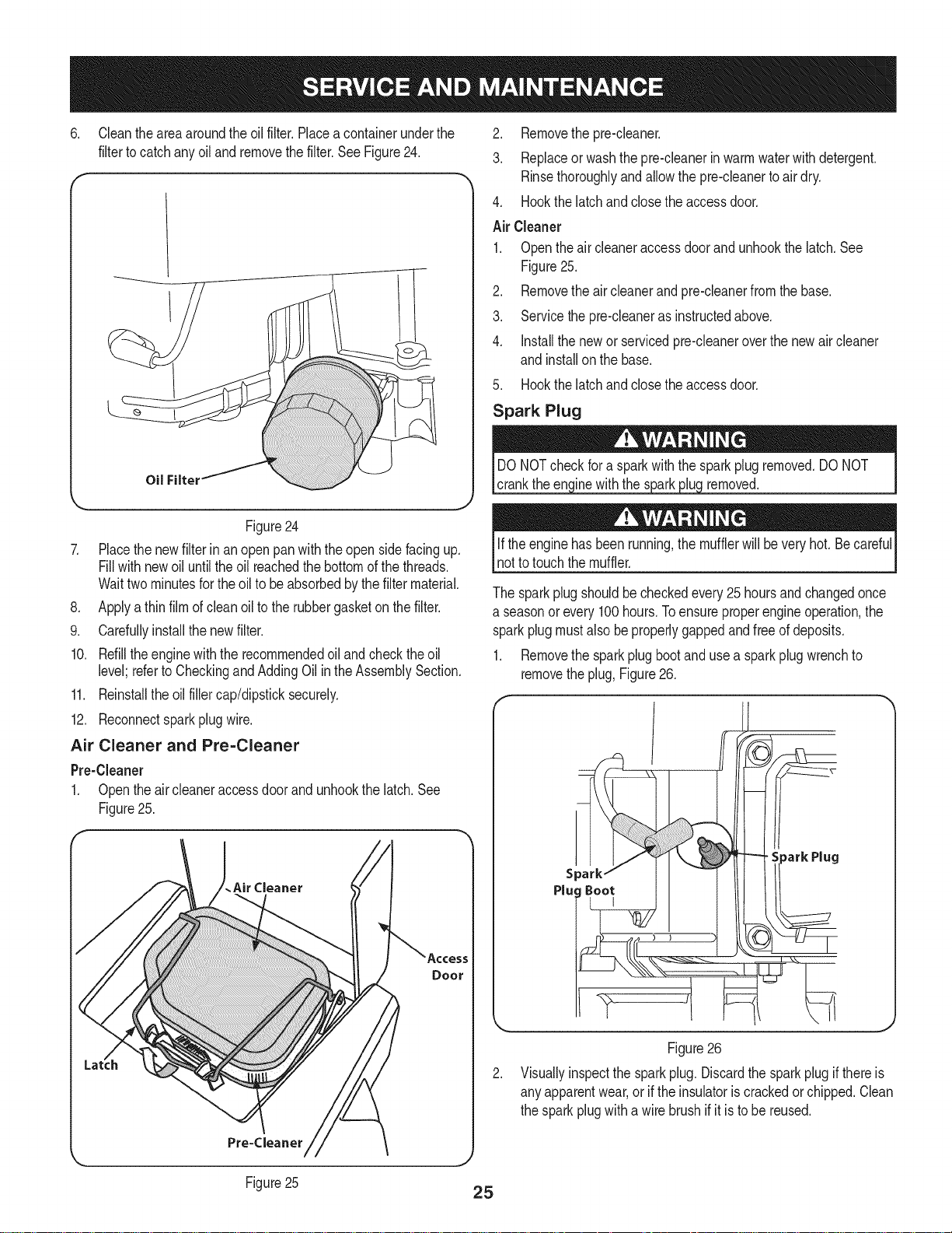
2. Locatetheoil drainhoseon theengine.SeeFigure23.
Beforeperforminganymaintenanceorrepairs,disengagethePTO,
movethedrivecontrolleversfullyoutwardintheneutralposition,
Iengagetheparkingbrake,stoptheengineandremovethekeyto
[preventunintendedstarting.
ENGINE MAINTENANCE
usedoil.
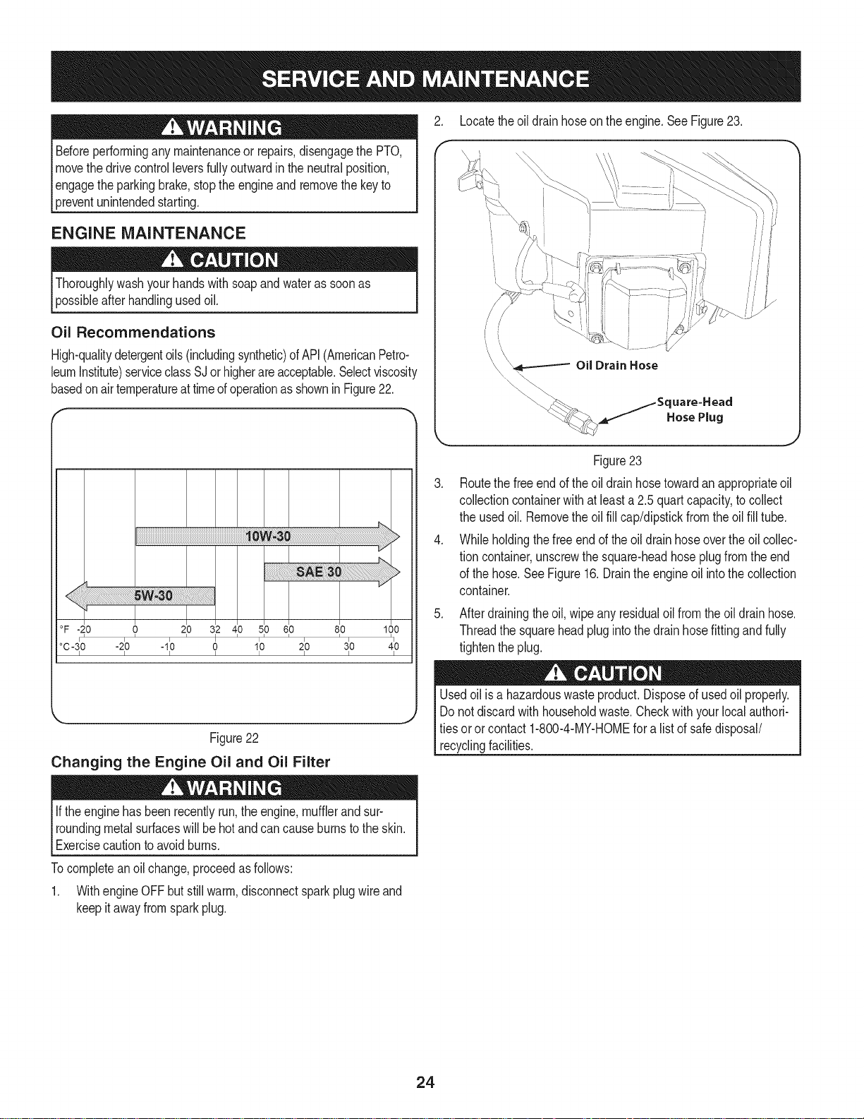
Oil Recommendations
High-qualitydetergentoils (includingsynthetic)ofAPI(AmericanPetro-
leumInstitute)serviceclassSJorhigherareacceptable.Selectviscosity
basedonairtemperatureat timeofoperationasshowninFigure22.
\
i,
/
Oil Drain Hose
._:_ j_Square=Heacl
HosePlug
Figure23
.
Routethefree endofthe oildrainhosetowardanappropriateoil
collectioncontainerwithat leasta 2.5quartcapacity,tocollect
theusedoil.Removetheoilfill cap/dipstickfromtheoil fill tube.
.
Whileholdingthe freeendof theoil drainhoseoverthe oilcollec-
tioncontainer,unscrewthesquare-headhoseplugfromtheend
ofthe hose.SeeFigure16.Draintheengineoil intothe collection
container.
°F-20 0 210 312 410 510 610 810 100
°C-3_0 -2_0 -1_0 0 1_0 2_0 3_0 4_0
I I I I I I I I
Figure22
Changing the Engine Oil and Oil Filter
If theenginehasbeenrecentlyrun,theengine,mufflerandsur-
roundingmetalsurfaceswillbe hotandcancauseburnstothe skin.
Exercisecautiontoavoidburns.
Tocompleteanoil change,proceedasfollows:
1. WithengineOFFbutstillwarm,disconnectsparkplugwireand
keepit awayfromsparkplug.
5. Afterdrainingtheoil, wipeanyresidualoilfromtheoil drainhose.
Threadthe squareheadpluginto thedrainhosefittingandfully
tightentheplug.
Usedoilisa hazardouswasteproduct.Disposeof usedoilproperly.
Donot discardwithhouseholdwaste.Checkwithyourlocalauthori-
J
tiesor orcontact1-800-4-MY-HOMEfora listof safedisposal/
recyclingfacilities.
24
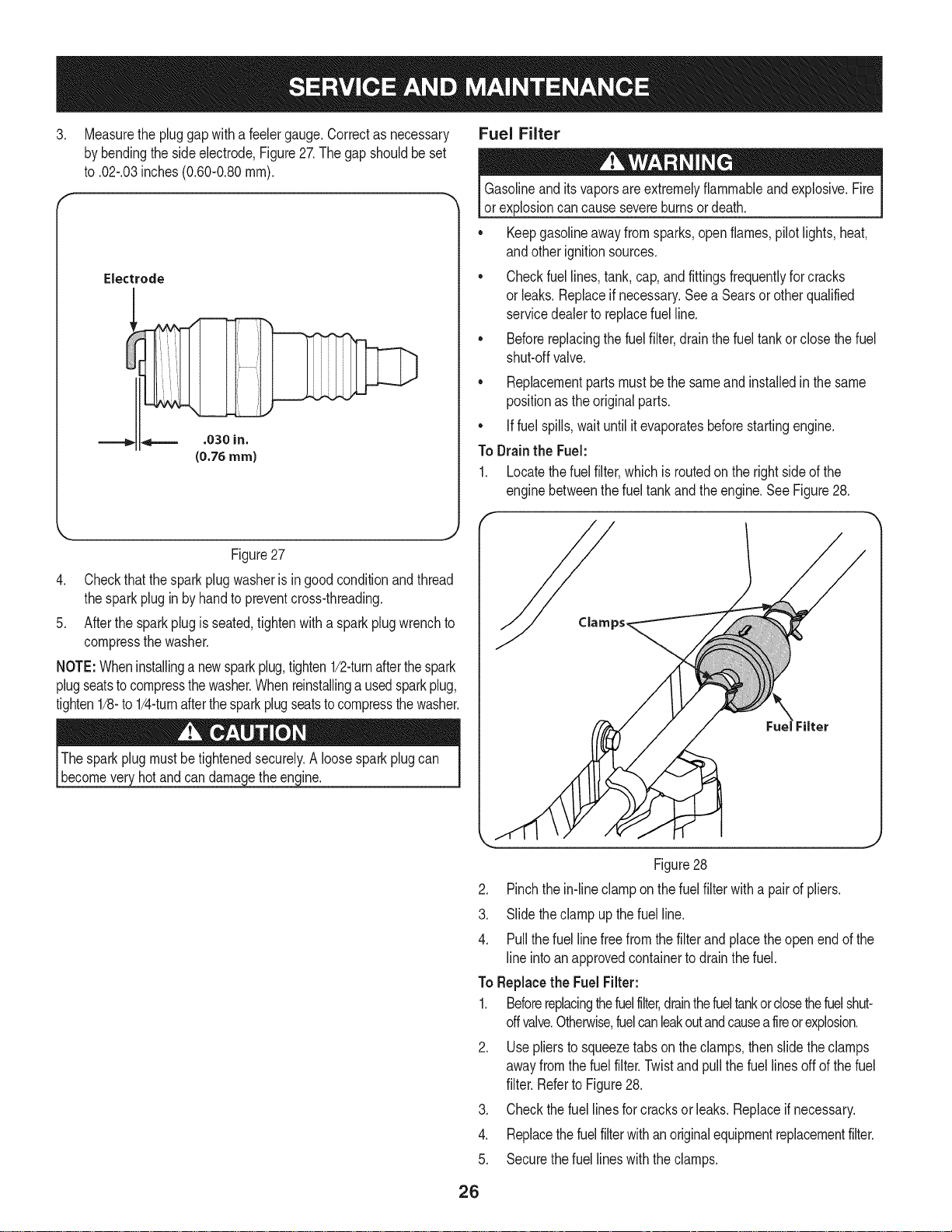
.
Cleantheareaaroundtheoilfilter. Placeacontainerunderthe
filtertocatchanyoil andremovethefilter.SeeFigure24.
f
2. Removethepre-cleaner.
3. Replaceor washthepre-cleanerin warmwaterwithdetergent.
Rinsethoroughlyandallowthe pre-cleanerto airdry.
4. Hookthelatchandclosethe accessdoor.
AirCleaner
1. Opentheaircleaneraccessdoorand unhookthelatch.See
Figure25.
2. Removethe aircleanerandpre-cleanerfromthebase.
3. Servicethepre-cleanerasinstructedabove.
4. Installthenewor servicedpre-cleaneroverthenewaircleaner
and installonthebase.
5. Hookthelatchandclosethe accessdoor.
Spark Plug
Oil Filter
Figure24
7. Placethe newfilterinanopenpanwiththeopensidefacingup.
Fillwithnewoil untilthe oil reachedthe bottomofthethreads.
Waittwo minutesfortheoil to beabsorbedbythefiltermaterial.
8. Applya thinfilmof cleanoilto therubbergasketonthefilter.
9. Carefullyinstallthenewfilter.
10. Refilltheenginewiththe recommendedoil andcheckthe oil
level;referto CheckingandAddingOilin theAssemblySection.
11. Reinstalltheoilfillercap/dipsticksecurely.
12. Reconnectsparkplugwire.
Air Cleaner and Pre=Cleaner
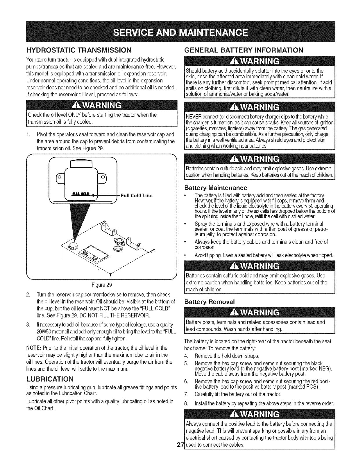
Pre-Cleaner
1. Openthe aircleaneraccessdoorandunhookthelatch.See
Figure25.
.Air Cleaner
cranktheen( inewiththe s_ removed.
ifthe enginehasbeenrunning,the mufflerwillbeveryhot. Becareful
notto touchthemuffler.
Thesparkplugshouldbecheckedevery25hoursandchangedonce
a seasonor every100hours.Toensureproperengineoperation,the
sparkplugmustalso beproperlygappedandfreeof deposits.
1. Removethesparkplugbootand usea sparkplugwrenchto
removetheplug,Figure26.
Figure25
Figure26
Visuallyinspectthe sparkplug.Discardthe sparkplugif thereis
anyapparentwear,or ifthe insulatoriscrackedorchipped.Clean
thesparkplugwitha wire brushif it isto be reused.
25
3. Measurethepluggapwitha feelergauge.Correctas necessary Fuel Filter
bybendingthesideelectrode,Figure27.Thegap shouldbe set
to.02-.03inches(0.60-0.80ram).
Gasolineandits vaporsareextremelyflammableand explosive.Fire
or explosioncancausesevereburnsordeath.
• Keepgasolineawayfromsparks,openflames,pilotlights,heat,
andotherignitionsources.
Electrode
• Checkfuel lines,tank,cap,andfittingsfrequentlyforcracks
or leaks.Replaceif necessary.Seea Searsor otherqualified
servicedealerto replacefuelline.
• Beforereplacingthefuelfilter,drainthefueltankorclosethefuel
shut-offvalve.
• Replacementpartsmustbethesameandinstalledinthesame
positionasthe originalparts.
• Iffuelspills,waituntilitevaporatesbeforestartingengine.
ToDrainthe Fuel:
1. Locatethefuel filter,whichisroutedontherightsideofthe
enginebetweenthefueltankandtheengine.SeeFigure28.
Figure27
4. Checkthatthesparkplugwasherisingoodconditionandthread
thesparkplugin by handtopreventcross-threading.
5. Afterthe sparkplugisseated,tightenwitha sparkplugwrenchto
compressthewasher.
NOTE:Wheninstallinga newsparkplug,tighten1/2-turnafterthespark
plugseatstocompressthewasher.Whenreinstallingausedsparkplug,
tighten1/8-to1/4-turnafterthesparkplugseatstocompressthewasher.
Thesparkplugmustbetightenedsecurely.A loosesparkplugcan
becomeveryhotandcan damagetheengine.
J
Figure28
2. Pinchthein-lineclamponthefuel filterwitha pairof pliers.
3. Slidetheclampup thefuel line.
4. Pullthefuel linefreefromthe filterand placetheopenendofthe
line intoanapprovedcontainertodrainthe fuel.
ToReplacethe Fuel Filter:
1. Beforereplacingthefuelfilter,drainthefueltankorclosethefuelshut-
offvalve.Otherwise,fuelcanleakoutandcauseafireorexplosion.
2. Usepliersto squeezetabsontheclamps,thenslidetheclamps
awayfromthefuel filter.Twistandpullthe fuellinesoffofthe fuel
filter.Referto Figure28.
3. Checkthe fuellinesforcracksorleaks.Replaceifnecessary.
4. Replacethefuelfilterwithanoriginalequipmentreplacementfilter.
5. Securethefuellineswiththeclamps.
26
HYDROSTATIC TRANSMiSSiON
Yourzeroturntractoris equippedwithdualintegratedhydrostatic
pumps/transaxlesthataresealedandaremaintenance-free.However,
thismodelis equippedwitha transmissionoil expansionreservoir.
Undernormaloperatingconditions,the oillevelin the expansion
reservoirdoesnot needtobecheckedand noadditionaloilis needed.
If checkingthereservoiroil level,proceedasfollows:
GENERAL BATTERY INFORMATION
Shouldbatteryacidaccidentallysplatterintotheeyesor ontothe
skin,rinsetheaffectedareaimmediatelywithcleancoldwater.If
thereisanyfurtherdiscomfort,seekpromptmedicalattention.Ifacid
spillsonclothing,firstdiluteit withcleanwater,thenneutralizewitha
solutionofammonia/wateror bakingsoda/water.
Checktheoil levelONLYbeforestartingthetractorwhenthe
transmissionoil is fullycooled.
1. Pivotthe operator'sseatforwardandcleanthereservoircapand
theareaaroundthe capto preventdebrisfromcontaminatingthe
transmissionoil. SeeFigure29.
-Full Cold Line
k,_ [ j
Figure29
2. Turnthe reservoircapcounterclockwisetoremove,thencheck
theoillevelin thereservoir.Oil shouldbe visibleatthebottomof
thecup,buttheoillevel mustNOTbe abovethe"FULLCOLD"
line.SeeFigure29.DONOTFILLTHERESERVOIR.
3. Ifnecessarytoaddoilbecaused sometypeofleakage,useaquality
20W50motoroilandaddonlyenoughoiltobringtheleveltothe"FULL
COLD"line.Reinstallthecapandfullytighten.
NOTE:Priorto theinitialoperationd thetractor,theoil levelinthe
reservoirmaybe slightlyhigherthanthemaximumdueto airin the
oil lines.Operationof thetractorwilleventuallypurgetheair fromthe
linesandthe oil levelwill settletothemaximum.
LUBRICATION
Usinga pressurelubricatinggun,lubricateallgreasefittingsandpoints
asnotedinthe LubricationChart.
Lubricateall otherpivotpointswithaqualitylubricatingoilas notedin
theOilChart.
NEVERconnect(ordisconnect)batterychargerclipstothebatterywhile
thechargeristurnedon,asitcancausesparks.Keepallsourcesofignition
(cigarettes,matches,lighters)awayfromthebattery.Thegasgenerated
duringchargingcanbecombustible.Asafurtherprecaution,onlycharge
thebatteryinawellventilatedarea.Alwaysshieldeyesandprotectskin
[andc othngwhenworkngnearbatteries.
Batteriescontainsulfuricacidandmayemitexplosivegases.Useextreme
cautionwhenhandlingbatteries.Keepbatteriesoutofthereachofchildren.
Battery Maintenance
• Thebatte_isfilledwithbatteryacidandthensealedatthefactory.
However,ifthebatteryisequippedwithfillcaps,removethemant
checkthelevelof the]iquidelectroly!einthebatteryevery50operating.
hours.Ifthelevelinanyofthesixcellshasdroppetbelowthebottomot
thesplitringinsidethefillhole,refillthecellwithdistilledwater.
• Spraytheterminalsandexposedwirewitha b.atteryterminal
sealer,orcoattheterminalswitha thincoatot greaseorpetro-
leumjelly,to protectagainstcorrosion.
• Alwayskeepthebatterycablesandterminalscleanandfreeof
corrosion.
• Avoidtipping.Evenasealedbatterywillleakelectrolytewhentipped.
Batteriescontainsulfuricacidandmayemitexplosivegases.Use
extremecautionwhenhandlingbatteries.Keepbatteriesoutof the
reachofchildren.
Battery Removal
Batteryposts,terminalsand relatedaccessoriescontainleadand
leadcompounds.Washhandsafterhandling.
Thebatteryislocatedonthe right/rearofthe tractorbeneaththeseat
boxframe.Toremovethebattery:
4. Removethe holddownstraps.
5. Remove!he hexcap screwandseresnut securingtheblack
negativebatteryleadto thenegativebatterypost-(markedNEG).
Movethecableawayfromthenegativebatterypost.
6. Removethe hexcap screwandsernsnut securingtheredposi-
tivebatteryleadto thepositivebatterypost(markedPOS).
7. Carefullyliftthebatteryoutofthetractor.
8. Installthe batterybyrepeatingtheabovestepsinthereverseorder.
Alwaysconnectthepositiveleadtothe batterybeforeconnectingthe
Inegativelead.Thiswillpreventsparkingorpossibleinjuryfroman
| electricalshortcausedbycontactingthetractorbodywithtoolsbeing
27_usedtoconnectthecables.
Chargingthe Battery
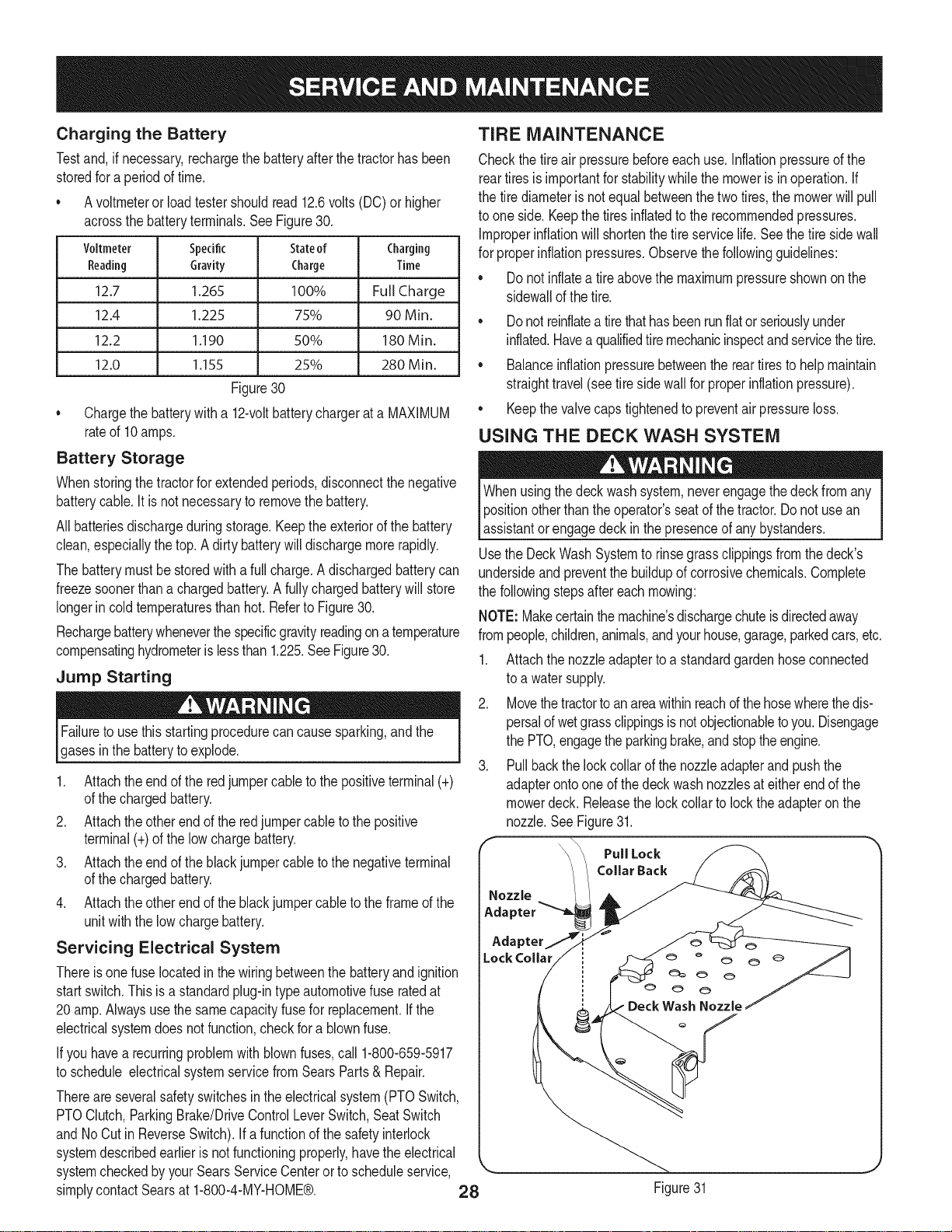
Testand,ifnecessary,rechargethebatteryafterthetractorhasbeen
storedforaperiodoftime.
• Avoltmeteror loadtestershouldread12.6volts(DC)or higher
acrossthebatteryterminals.SeeFigure30.
Voltmeter Specific Charging
Reading Gravity Time
12.7 1.265 Full Charge
12.4 1.225 90 Min.
12.2 1.190 180 Min.
12.0 1.155 280 Min.
Figure30
* Chargethebatterywitha 12-voltbatterychargerata MAXIMUM
rateof 10amps.
Battery Storage
Whenstoringthetractorfor extendedperiods,disconnectthenegative
batterycable.It is notnecessaryto removethebattery.
All batteriesdischargeduringstorage.Keeptheexteriorof thebattery
clean,especiallythetop.Adirty batterywilldischargemorerapidly.
Thebatterymustbe storedwitha full charge.A dischargedbatterycan
freezesoonerthana chargedbattery.A fullychargedbatterywillstore
longerin coldtemperaturesthan hot.RefertoFigure30.
Rechargebatterywheneverthespecificgravityreadingona temperature
compensatinghydrometerislessthan 1.225.SeeFigure30.
Jump Starting
Failuretousethisstartingprocedurecan causesparking,andthe
gasesinthebatterytoexplode.
1. Attachtheendof theredjumpercableto thepositiveterminal(+)
ofthe chargedbattery.
2. Attachtheotherend ofthe redjumpercabletothe positive
terminal(+)ofthelowchargebattery.
3. Attachtheendof theblackjumpercableto thenegativeterminal
ofthe chargedbattery.
4. Attachtheotherend ofthe blackjumpercabletothe frameofthe
unitwiththe lowchargebattery.
Servicing Electrical System
Thereis onefuselocatedinthewiringbetweenthe batteryandignition
startswitch.Thisisa standardplug-intypeautomotivefuse ratedat
20amp.Alwaysusethesamecapacityfusefor replacement.Ifthe
electricalsystemdoesnotfunction,checkfor a blownfuse.
Ifyouhavea recurringproblemwithblownfuses,call 1-800-659-5917
toschedule electricalsystemservicefromSearsParts& Repair.
Thereareseveralsafetyswitchesintheelectricalsystem(PTOSwitch,
PTOClutch,ParkingBrake/DriveControlLeverSwitch,SeatSwitch
andNoCutin ReverseSwitch).Ifa functionofthe safetyinterlock
systemdescribedearlieris notfunctioningproperly,havethe electrical
systemcheckedbyyourSearsServiceCenterorto scheduleservice,
simplycontactSearsat 1-800-4-MY-HOME®. 28
Stateof
Charge
100%
75%
50%
25%
TIRE MAINTENANCE
Checkthe tireair pressurebeforeeachuse.Inflationpressureofthe
reartiresisimportantforstabilitywhilethemoweris in operation.If
thetire diameteris notequalbetweenthetwotires,themowerwill pull
toone side.Keepthetiresinflatedtothe recommendedpressures.
Improperinflationwillshortenthe tireservicelife.Seethetire sidewall
forproperinflationpressures.Observethe followingguidelines:
• Donotinflatea tireabovethemaximumpressureshownonthe
sidewallofthe tire.
• Donotreinflateatirethathasbeenrunflatorseriouslyunder
inflated.Havea qualifiedtiremechanicinspectandservicethetire.
• Balanceinflationpressurebetweenthereartiresto helpmaintain
straighttravel(seetiresidewallfor properinflationpressure).
• Keepthevalvecapstightenedto preventair pressureloss.
USING THE DECK WASH SYSTEM
Whenusingthedeckwashsystem,neverengagethedeckfromany
positionotherthan theoperator'sseatofthetractor.Donotusean
assistantorengagedeckinthe presenceof anybystanders.
UsetheDeckWashSystemtorinsegrassclippingsfromthedeck's
undersideandpreventthe buildupof corrosivechemicals.Complete
thefollowingstepsaftereachmowing:
NOTE:Makecertainthemachine'sdischargechuteisdirectedaway
frompeople,children,animals,andyourhouse,garage,parkedcars,etc.
1. Attachthenozzleadaptertoa standardgardenhoseconnected
toa watersupply.
2. Movethetractortoanareawithinreachofthe hosewherethedis-
persalofwetgrassclippingsisnotobjectionabletoyou.Disengage
thePTO,engagethe parkingbrake,andstoptheengine.
3. Pullbackthelockcollarofthe nozzleadapterandpushthe
adapterontooneofthe deckwashnozzlesateitherendof the
mowerdeck.Releasethelockcollarto locktheadapteronthe
nozzle.SeeFigure31.
CollarBack
PullLock
Adapter
Lock Collar
Figure31
4. Turnonthewatersupply.
5. Fromthetractoroperator'sseat,starttheengineandengagethePTO.
Allowtorunasneeded.DisengagethePTOandstoptheengine.
6. Turnoffthewatersupply.
7. Pullbackthelockcollarofthenozzleadaptertodisconnectthe
adapterfromthenozzle.
8. Repeatthepreviousstepstocleanthedeckusingthenozzleat
theotherendofthedeck.
CLEANING THE SPINDLE PULLEYS
Oncea monthremovethe beltcoversto removeanyaccumulationof
grassclippingsfromaroundthespindlepulleysandV-belt.Cleanmore
oftenwhenmowingtall,dry grass.
USING THE TRANSMISSION BYPASS RODS
If forany reasonthetractorwill notdriveor youwishtomovethe
tractor,thetwo hydrostatictransmissionsareequippedwitha bypass
rodthatwillallowyouto manuallymovethetractorshortdistances.
Donottowthetractor,evenwith thebypassrodengaged.Serious
transmissiondamagewillresultfromdoingso.
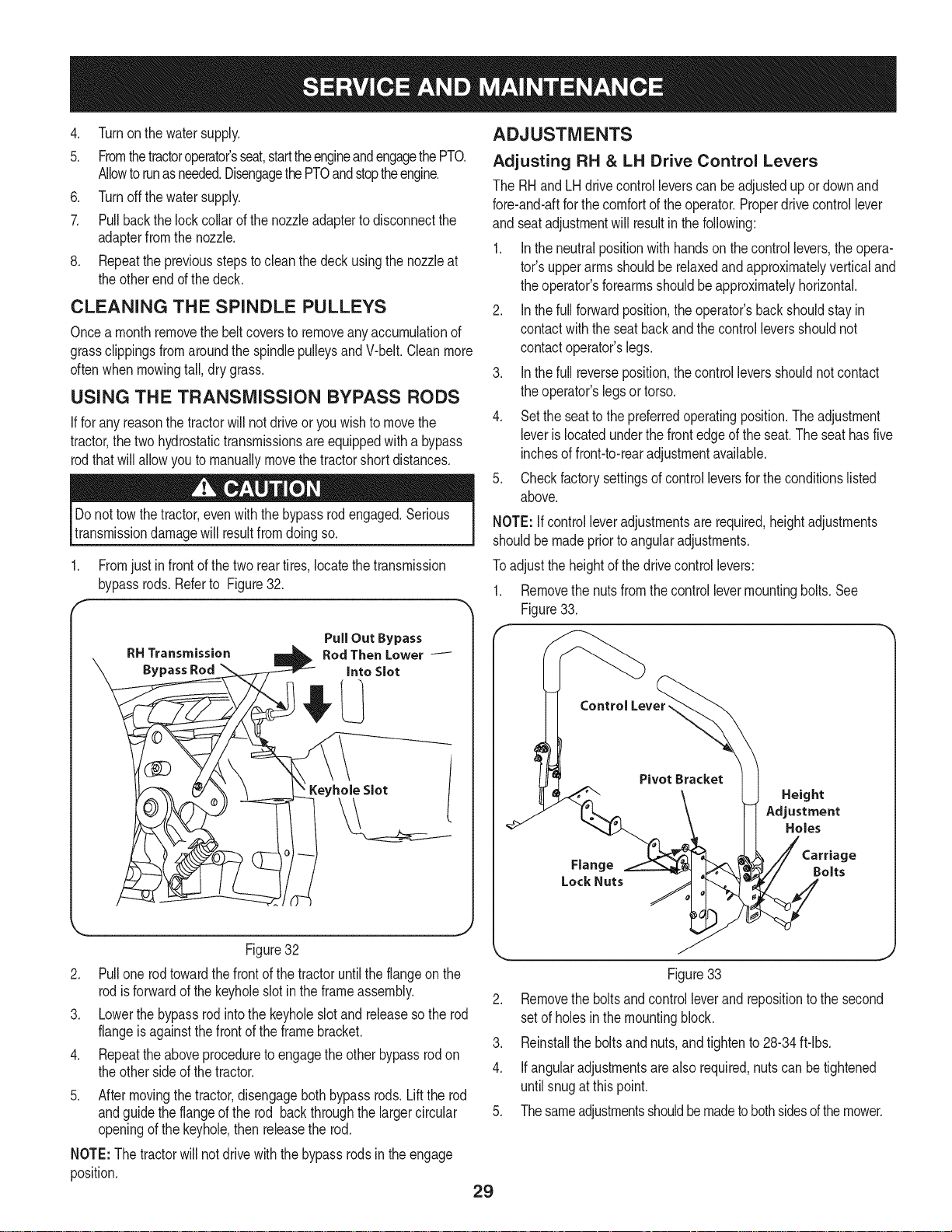
1. Fromjustin frontof the tworeartires,locatethe transmission
bypassrods.Referto Figure32.
f
ADJUSTMENTS
Adjusting RH & LH Drive Control Levers
TheRHandLH drivecontrolleverscan beadjustedupor downand
fore-and-aftforthecomfortof theoperator.Properdrivecontrollever
and seatadjustmentwillresultinthefollowing:
1. Inthe neutralpositionwithhandson thecontrollevers,theopera-
tot'supperarmsshouldbe relaxedandapproximatelyverticaland
theoperator'sforearmsshouldbeapproximatelyhorizontal.
2. Inthe fullforwardposition,theoperator'sbackshouldstayin
contactwiththeseatbackandthe controlleversshouldnot
contactoperator'slegs.
3. Inthe full reverseposition,thecontrolleversshouldnotcontact
theoperator'slegsor torso.
4. Setthe seatto thepreferredoperatingposition.Theadjustment
leveris locatedunderthefrontedgeof theseat.Theseathasfive
inchesof front-to-rearadjustmentavailable.
5. Checkfactorysettingsofcontrolleversfortheconditionslisted
above.
NOTE:If controlleveradjustmentsare required,heightadjustments
shouldbemadepriortoangularadjustments.
Toadjustthe heightofthedrivecontrollevers:
1. Removethenutsfromthecontrollevermountingbolts.See
Figure33.
Figure32
2. Pullonerodtowardthefrontof thetractoruntilthe flangeonthe
rodisforwardof thekeyholeslotinthe frameassembly.
3. Lowerthebypassrodintothekeyholeslotandreleasesothe rod
flangeis againstthefrontof theframebracket.
4. Repeattheaboveprocedureto engagetheotherbypassrodon
theothersideof thetractor.
5. Aftermovingthetractor,disengagebothbypassrods.Lifttherod
andguidetheflangeofthe rod backthroughthe largercircular
openingofthe keyhole,then releasetherod.
NOTE:The tractorwillnotdrivewiththebypassrodsinthe engage
position.
Control Lever,
Pivot Bracket
Height
Adjustment
Holes
Flange Bolts
Lock Nuts
Figure33
2. Removethe boltsandcontrolleverandrepositiontothe second
setofholesinthemountingblock.
3. Reinstallthe boltsandnuts,andtightento 28-34ft-lbs.
4. Ifangularadjustmentsarealso required,nutscan betightened
untilsnugatthispoint.
5. Thesameadjustmentsshouldbemadetobothsidesof themower.
29
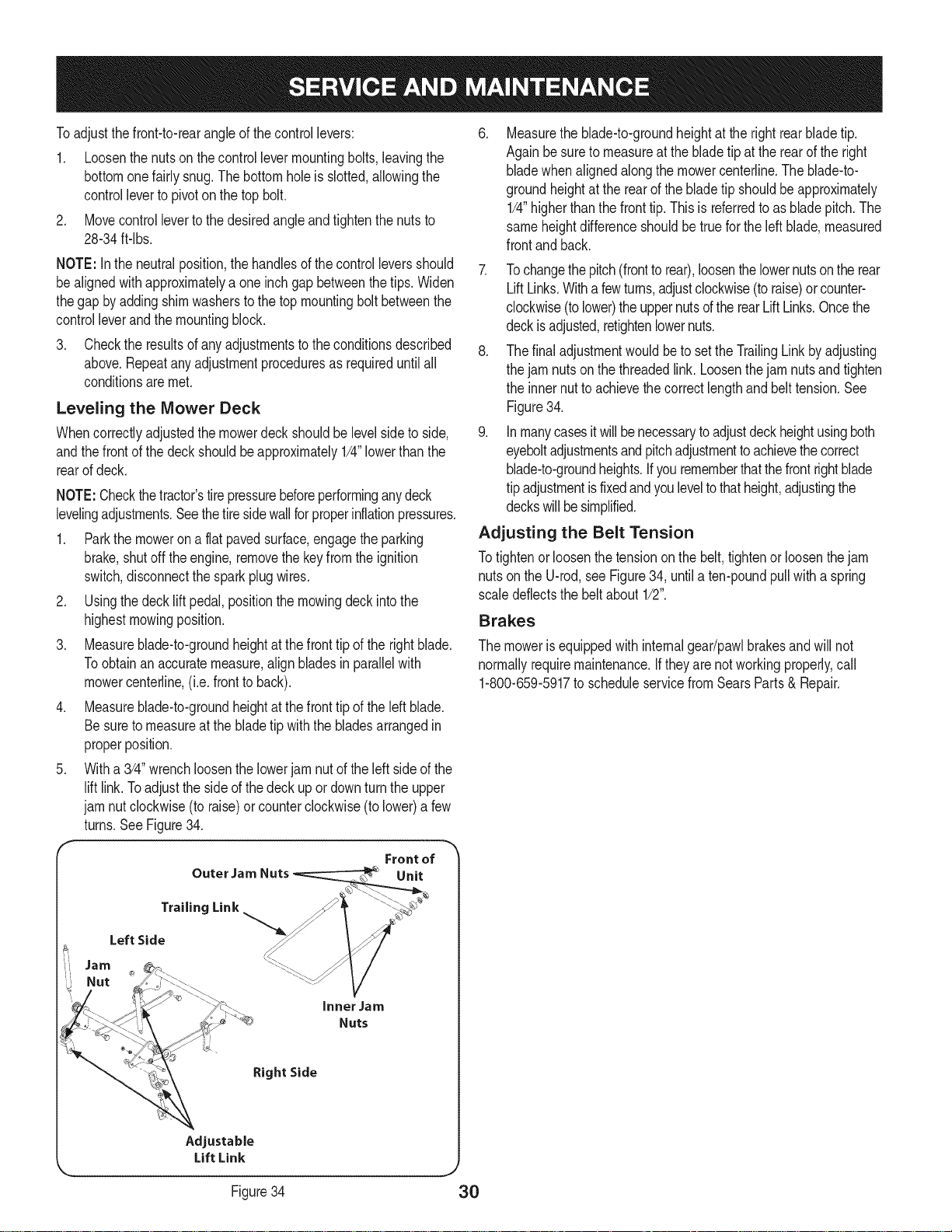
Toadjustthe front-to-rearangleof thecontrollevers:
1. Loosenthenutsonthecontrollevermountingbolts,leavingthe
bottomonefairlysnug.Thebottomholeis slotted,allowingthe
controlleverto pivoton thetop bolt.
2. Movecontrolleverto thedesiredangleandtightenthenutsto
28-34ft-lbs.
NOTE:Intheneutralposition,thehandlesofthecontrolleversshould
bealignedwithapproximatelya oneinchgap betweenthetips.Widen
thegap by addingshimwasherstothetop mountingboltbetweenthe
controlleverandthe mountingblock.
3. Checkthe resultsofanyadjustmentstotheconditionsdescribed
above.Repeatanyadjustmentproceduresas requireduntilall
conditionsaremet.
Leveling the Mower Deck
Whencorrectlyadjustedthemowerdeckshouldbe levelsideto side,
andthefrontof thedeckshouldbeapproximately1/4"lowerthanthe
rearofdeck.
NOTE:Checkthetractor'stirepressurebeforeperforminganydeck
levelingadjustments.Seethe tiresidewallforproperinflationpressures.
1. Parkthe mowerona flatpavedsurface,engagetheparking
brake,shutoff theengine,removethekeyfromthe ignition
switch,disconnectthe sparkplugwires.
2. Usingthedecklift pedal,positionthemowingdeckintothe
highestmowingposition.
3. Measureblade-to-groundheightatthe fronttipof therightblade.
Toobtainanaccuratemeasure,alignbladesinparallelwith
mowercenterline,(i.e.frontto back).
4. Measureblade-to-groundheightatthe fronttipof theleftblade.
Besureto measureatthebladetipwiththebladesarrangedin
properposition.
5. Witha 3/4"wrenchloosenthelowerjam nutofthe leftsideof the
lift link.Toadjustthe sideof thedeckup ordownturn theupper
jam nutclockwise(to raise)orcounterclockwise(tolower)a few
turns.SeeFigure34.
.
Measuretheblade-to-groundheightatthe rightrearbladetip.
Againbesureto measureatthebladetipattherearofthe right
bladewhenalignedalongthe mowercenterline.The blade-to-
groundheightattherearof thebladetip shouldbeapproximately
1/4"higherthanthefronttip.Thisis referredto as bladepitch.The
sameheightdifferenceshouldbetrueforthe leftblade,measured
frontandback.
7. Tochangethepitch(frontto rear),loosenthe lowernutsonthe rear
LiftLinks.Withafewturns,adjustclockwise(to raise)orcounter-
clockwise(tolower)theuppernutsofthe rearLiftLinks.Oncethe
deckisadjusted,retightenlowernuts.
8. Thefinaladjustmentwouldbeto settheTrailingLinkbyadjusting
thejam nutson thethreadedlink.Loosenthejamnutsandtighten
theinnernutto achievethecorrectlengthand belttension.See
Figure34.
9. Inmanycasesitwill benecessarytoadjustdeckheightusingboth
eyeboltadjustmentsandpitchadjustmenttoachievethecorrect
blade-to-groundheights.Ifyourememberthatthefrontrightblade
tipadjustmentisfixedandyouleveltothatheight,adjustingthe
deckswillbesimplified.
Adjusting the Belt Tension
Totightenorloosenthetensiononthe belt,tightenorloosenthejam
nutson theU-rod,see Figure34,untila ten-poundpullwitha spring
scaledeflectsthebeltabout1/2".
Brakes
Themoweris equippedwith internalgear/pawlbrakesandwill not
normallyrequiremaintenance.Iftheyarenotworkingproperly,call
1-800-659-5917to scheduleservicefromSearsParts& Repair.
Jam
Nut
Front of
Outer Jam Nuts Unit
Trailing Link
Left Side
Inner Jam
Nuts
Right Side
Adjustable
Lift Link
Figure34 30
 Loading...