

Craftsman 235199050 Owner’s Manual
Owner's Manual
CRAFTSMIIN"
1/2" Drive Ultra-Duty
PISTOL GRIP IMPACT WRENCH
Model No.
235.199050
• Safety
° Operation
° Maintenance
° Service and
Adjustments
= Parts List
• Espa_oi
_WARNING:
Before using this Impact Wrench
read this manual and follow all its
Safety and Operating Instructions.
Sears, Roebuck and Co., Hoffman Estates, IL 60179
Owner'= M=nual P7360 (1-98) Printed In USA
TABLE OF CONTENTS
PAGE
Two Year Warranty
Safety
Warning Labels
Notice, Warning and Caution
Placing Tool In Service
Using the Tool
Operation
Air Supplyand Connections
Using the Power Management System
Specifications
Maintenance
Lubrication
Service and Adjustment
Disassembly
Assembly
Troubleshooting
Parts List
Exploded Drawing
Parts for Ordering
EspaSol 20-37
3-5
6-7
8-15
17-19
2
16
FULL TWO YEAR WARRANTY
If this product fails due to a defect in material or workmanship within
two years from the date of purchase, Sears will at its option, repair or
replace it free of charge.
Return this product to a Sears Service Center for repair,or to place of
purchase for replacement.
This warranty gives you specific legal rights, and you may also have
other rights which vary from state to state.
Sears, Roebuck and Co., Dept. 817WA, Hoffman Estates, IL 60179
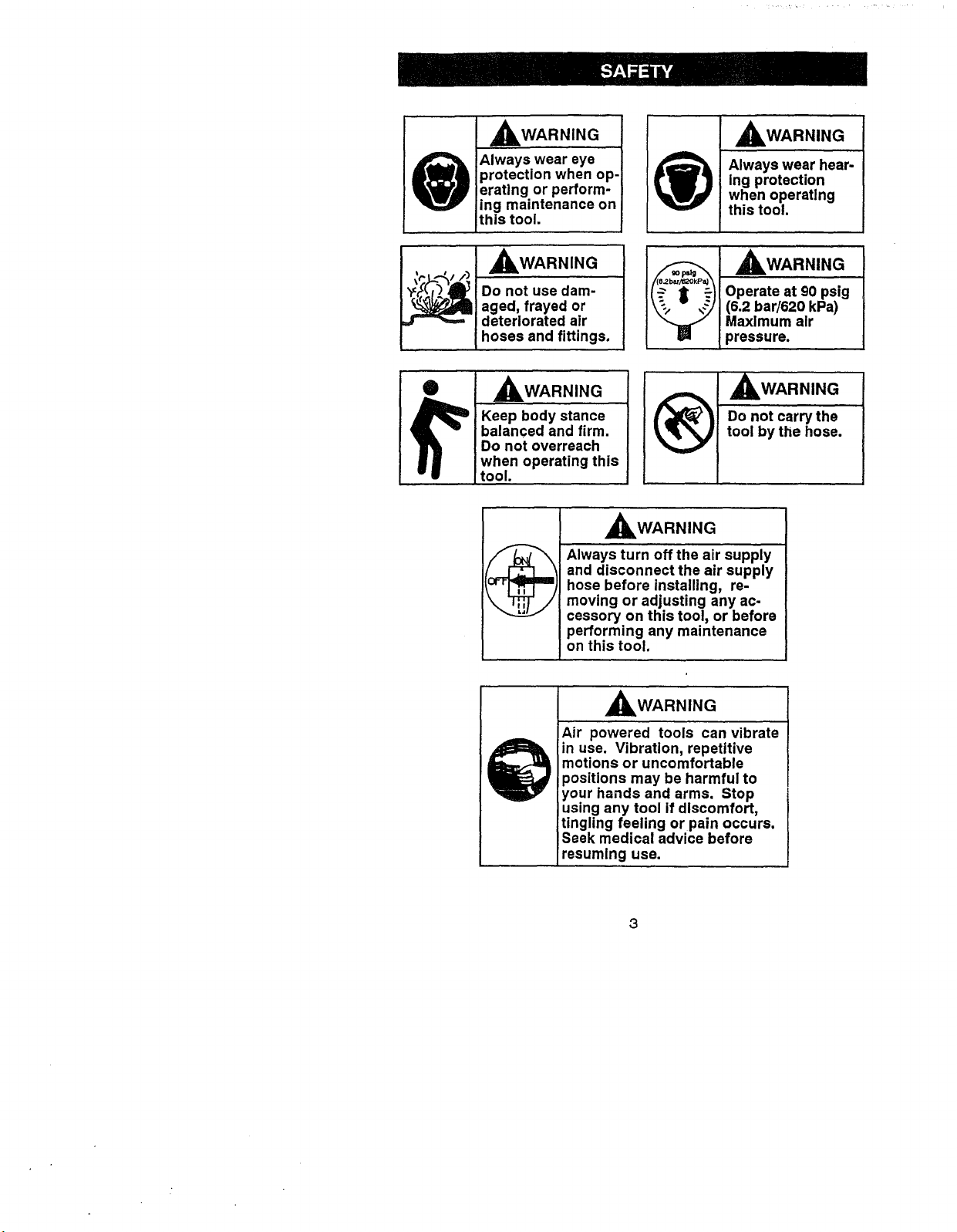
,_WARNING
Always wear eye
protection when op-
erating or perform-
ing maintenance on
this tool.
_WARNING
Always wear hear-
ing protection
when operating
this tool.
_._l_gl_ Do not use dam- Operate at 90 psig
aged, frayed or (6.2 bar/620 kPa)
deteriorated air Maximum air
hoses and fittings, i pressure.
Keep body stance Do not carry the
balanced and firm. tool by the hose.
Do not overreach
when operating this
tool.
,_WARNING
Always turn off the air supply
and disconnect the air supply
hose before installing, re-
moving or adjusting any ac-
cessory on this tool, or before
performing any maintenance
on this tool.
,_WARNING
Air powered tools can vibrate
in use. Vibration, repetitive
motions or uncomfortable
positions may be harmful to
your hands and arms. Stop
using any tool if discomfort,
tingling feeling or pain occurs.
Seek medical advice before
resuming use.
3
_WARNING is used to indicate the presence of a hazard which
can cause severe personal Injury or death if thewarning Is Ignored.
CAUTION is used to indicate the presence of a hazard which will
or can cause minor personal injury or property damage if the cau-
tion is Ignored.
NOTICE is used to notify people of installation, operation or main-
tenance information which is important but not hazard related.
This Craftsman Impact Wrench is
designed for use in general auto-
motive repair, tire service and
heavy duty fleet applications.
,_WARNING:
Important safety information en-
closed.
Read this manual before operating
tool.
It is the responsibility of an em-
ployer to place the information in
this manual into the hands of any-
one who operates this device.
Failure to observe the following
warnings could result in injury.
PLACING TOOL IN SERVICE
• Always operate, inspect and
maintain this tool in accordance
with all regulations (local, state,
federal and country), that may
apply to hand-held/hand-oper-
ated pneumatic tools.
• For safety, top performance,
and maximum durability of
parts, operate this toolat
90 psig (6.2 bar/620 kPa) maxi-
mum air pressure at the inlet
with 3/8" (10 mm) inside diame-
ter air supply hose.
° Always turn offthe air supply
and disconnect the air supply
hose before installing, removing
or adjusting any accessory on
this tool, or before performing
any maintenance on this tool.
• Do not use damaged, frayed or
deteriorated airhoses and fit-
tings.
° Be sure all hoses and fittings
are the correct size and are
tightly secured. See Figure 1 for
a typical piping arrangement.
° Always use clean, dry air at
90 psig maximum air pressure.
Dust, corrosive fumes and/or
excessive moisture can ruin the
motor of an air tool.
° Do not lubricate tools with flamo
mable or volatile liquids such as
kerosene, diesel or jet fuel.
PLACING TOOL IN SERVICE
(continued)
• Do not removeany labels. Re-
place any damagedlabel.
• The use of a hosewhip is rec-
ommended. A couplercon-
nected directlyto the air inletin-
creases tool bulkand de-
creases tool maneuverability.
• For maximum performance, the
coupler on thewallshould be
the next size largerthan the
coupler usedon the tool.The
coupler closesttothe tool
should notbe lessthanthe
proper air supplyhose size.
USING THE TOOL
• Always wear eye protection
when operatingor performing
maintenance on this tool.
• Always wear hearing protection
when operating this tool.
• Keep hands, loose clothing and
long hair away from rotating
end of tool.
• Note the position of the revers-
ing lever before operating the
tool so as to be aware of the
direction of rotation when oper-
ating the throttle.
• Anticipate and be alert for sud-
den changes in motion during
start-up and operation of any
power tool.
• Keep body stance balanced
and firm. Do not overreach
when operating this tool. High
reaction torques can occur at or
below the recommended air
pressure.
• Tool shaft may continue to ro-
tate briefly after throttle is re-
leased.
• Air powered tools can vibrate in
use. Vibration, repetitive mo-
tions or uncomfortable positions
may be harmful to your hands
and arms. Stop using any tool ff
discomfort, tingling feeling or
pain occurs. Seek medical ad-
vice before resuming use.
• Use accessories recommended
by Craftsman.
• Use only impact sockets and
accessories. Do not use hand
(chrome) sockets or accesso-
ries.
• Impact wrenches are not torque
wrenches. Connections requir-
ing specific torque must be
checked with a torque meter af-
ter fitting with an impact
wrench.
• This tool is not designed for
working in explosive atmo-
spheres.
° This tool is not insulated against
electric shock.
NOTICE: The use of other than
genuine Craftsman replacement
parts may result in safety hazards,
decreased tool performance, in-
creased maintenance, and may
invalidate all warranties.
Repairs should be made only by
authorized trained personnel.
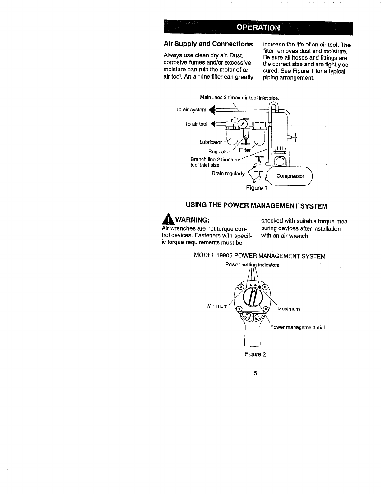
Air Supply and Connections
Always use clean dry air.Dust,
corrosivefumes and/or excessive
moisture can ruinthe motor of an
air tool. An air line filter can greatly
Main lines 3 timesair tool inletsize.
Toairtool
Lubri
Branch line 2 times air - _ I [_ _1 I
toolinletsize _,,//_/-.-,- ,t =
Drainregulady_ Compressor_
USING THE POWER MANAGEMENT SYSTEM
increasethe life of anair tool. The
filterremoves dustand moisture.
Besure all hoses andfittingsare
the correct sizeand are tightlyse-
cured.See Figure1 for a typical
pipingarrangement.
Figure 1
,_WARNING:
Airwrenches are nottorquecon-
trotdevices. Fastenerswith specif-
ictorquerequirementsmust be
MODEL 19905 POWER MANAGEMENT SYSTEM
Power settingindicators
Minimum
Figure2
checked with suitabletorque mea-
suringdevices afterinstallation
with an air wrench.
Maximum
Power management dial
6
YourImpactWrench incorporates
a Power Management System that
allows you to select four power
output settings. These settings
range from minimum power output
through maximum power output in
the forward direction only. The Air
Wrench will always operate at
maximum power output in the re-
verse direction, no matter what
power output level is selected.
AWARNING:
The four powersettingindicators
of increasingsize onthe rear of
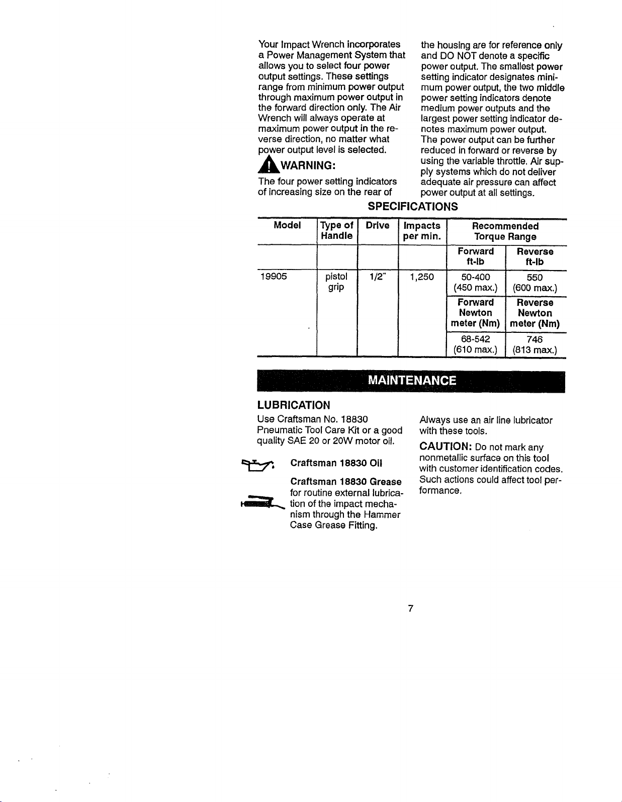
SPECIFICATIONS
the housing are for reference only
and DO NOT denote a specific
power output. The smallest power
setting indicator designates mini-
mum power output, the two middle
power setting indicators denote
medium power outputs and the
largest power setting indicator de-
notes maximum power output.
The power output can be further
reduced in forward or reverse by
using the variable throttle. Air sup-
ply systems which do not deliver
adequate air pressure can affect
power output at all settings.
Model Type of Drive Impacts
Handle per min.
19905
pistol 1/2'" 1,250
grip
LUBRICATION
Use Craftsman No. 18830
Pneumatic Tool Care Kit or a good
quality SAE 20 or 20W motor oil.
Craftsman 18830 Oil
Craftsman 18830 Grease
for routine external lubrica-
tion of the impact mecha-
nism through the Hammer
Case Grease Fitting.
Recomm'ended
Torque Range
Forward
ft.lb
50-400
(450 max.)
Forward
Newton
meter (Nm)
68-542
(610 max.)
Reverse
ft-lb
55O
(600 max.)
Reverse
Newton
meter (Nm)
746
(813 max,)
Always use an air line lubricator
with these tools.
CAUTION: Donot mark any
nonmetallic surface on this tool
with customer identification codes.
Such actions could affect tool per-
formance.
7
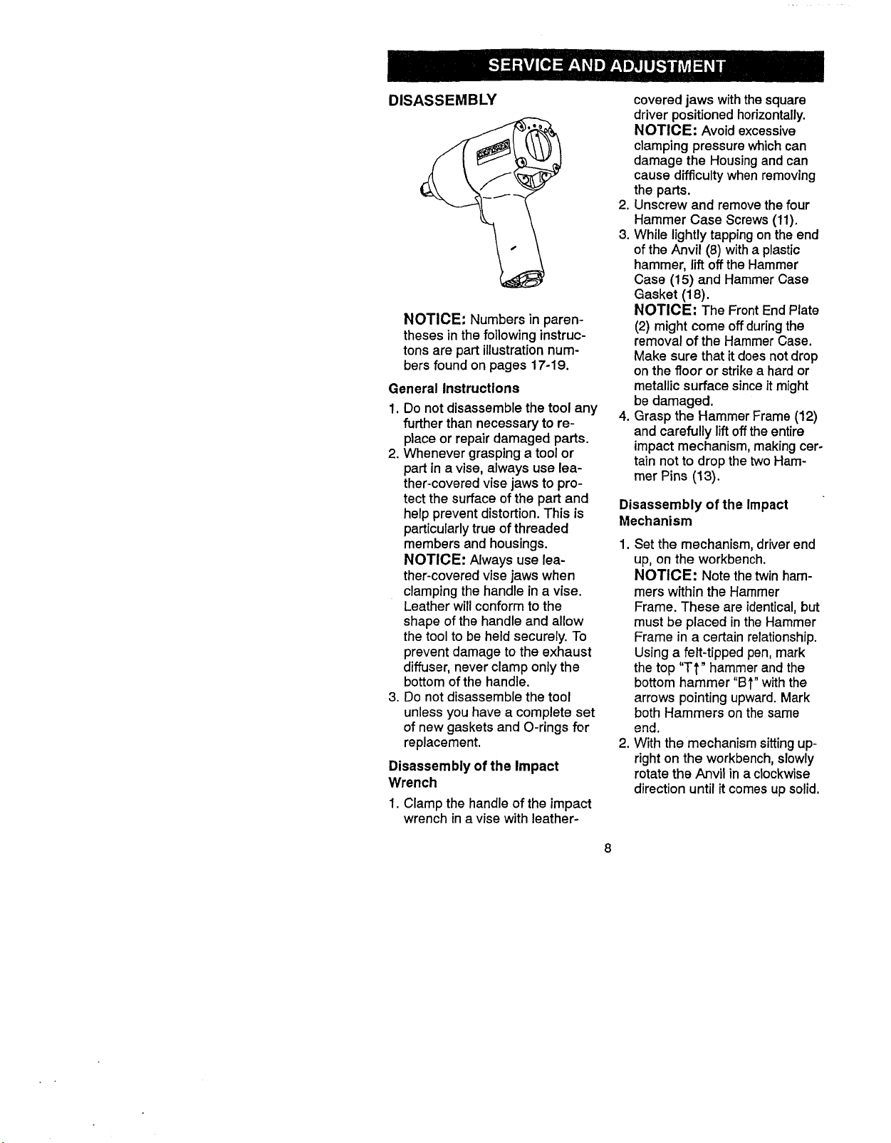
DISASSEMBLY
NOTICE: Numbers in paren-
theses in the following instruc-
tons are part illustration num-
bers found on pages 17-19.
General Instructions
1. Do not disassemble the tool any
further than necessary to re-
place or repair damaged parts.
2. Whenever grasping atool or
part in a vise, always use lea-
ther-covered vise jaws to pro-
tect the surface of the part and
help prevent distortion. This is
particularly true of threaded
members and housings.
NOTICE: Always use lea-
ther-covered vise jaws when
clamping the handle in a vise.
Leather will conform to the
shape of the handle and allow
the tool to be held securely. To
prevent damage to the exhaust
diffuser, never clamp only the
bottom of the handle.
3. Do not disassemble the tool
unless you have a complete set
of new gaskets and O-rings for
replacement.
Disassembly of the Impact
Wrench
1. Clamp the handle of the impact
wrench in a vise with leather-
covered jaws withthe square
driver positioned horizontally.
NOTICE: Avoid excessive
clamping pressure which can
damage the Housing and can
cause difficulty when removing
the parts.
2. Unscrew and remove the four
Hammer Case Screws (11).
3. While lightly tapping on the end
of the Anvil (8) with a plastic
hammer, lift off the Hammer
Case (15) and Hammer Case
Gasket (18).
NOTICE: The Front End Plate
(2) might come off during the
removal of the Hammer Case.
Make sure that itdoes not drop
on the floor or strike a hard or
metallic surface since it might
be damaged.
4. Grasp the Hammer Frame (12)
and carefully lift off the entire
impact mechanism, making cer-
tain not to drop the two Ham-
mer Pins (13).
Disassembly of the Impact
Mechanism
1. Set the mechanism, driver end
up, on the workbench.
NOTICE: Note the twin ham-
mers within the Hammer
Frame. These are identical, but
must be placed in the Hammer
Frame in a certain relationship.
Using a felt-tipped pen, mark
the top "Tt" hammer and the
bottom hammer "Bt" with the
arrows pointing upward. Mark
both Hammers on the same
end.
2. With the mechanism sitting up-
right on the workbench, slowly
rotate the Anvil in a clockwise
direction until it comes up solid.

NOTICE: If you continueto ro-
tate the Anvil, it will cam the
Hammers out of engagement.
Don't do this; merely rotate the
Anvil until itcomes up solid.
3. Hold the Hammer Frame firmly
and without disturbing the ham-
mers, gently lift the Anvil while
simultaneously rotating it clock-
wise about 1/8 of a turn from
the Hammer Frame.
4. With the Anvil removed, lift out
the two Hammer Pins. The twin
hammers are now free to slide
from the Hammer Frame, Be
careful do not to drop them.
Disassembly of the Motor
NOTICE: When pulling, disas-
sembling or assemblingthe mo-
tor, we recommendreplace-
ment of the MotorGasket (7).
1. Remove the MotorAssembly
from the Housing(19) bypush-
ingon Power Management Dial
(41) from the back ofthe
Housing. See Figure3.
splined end of the Rotor (5) with
a plastic hammer. If the Front
End Plate does not come loose,
secure a center punchin a vise
with the point angled downward
and outward from the vise.
Then, grasp the Cylinder and
Front End Plate in one hand
and position the hole in the end
of the Rotor against the punch.
NOTICE: Be careful not to
drop the Cylinder since it can
be damaged by hitting a hard
surface.
Using the other hand, tap the
punch with a hammer while
pressing the Rotor against the
punch. After a few taps, the
Front End Plate will slide off of
the Cylinder.
NOTICE: To prevent damage
to the Cylinder, do not tap or
strike Cylinder on a hard or me-
tallic surface when removing
the Rotor Bearings (3).
4,
To remove the Front Rotor
Bearing, hold the Front End
Plate with Front Rotor Bearing
down and tap the Front End
Plate on a flat, nonmetallic
surface such as awork bench.
This will loosen the Front Rotor
Bearing so that it will drop out of
the Front End Plate. See
Figure 4.
Figure 3
NOTICE; If the Motor Assem-
bly cannot be removed from the
Housing by pushing, tap the
Power Management Dial lightly
until the Motor Assembly is free.
2. Remove the Power Manage-
ment Dial from the rear of the
Cylinder (1). Remove the Power
Management Dial Seal (42) if it
needs to be replaced.
3. Remove the Front End Plate (2)
from the Cylinder by tapping the
Front end plate
Front rotor bearing
Bench with nonmetallic surface
Figure 4
5. Remove the Rear RotorBear-
ingRetainer(6) from the rear of
the Rotor (5). The Rotor can
now be removed from the Cylino
der. Remove the Vanes (4) from
the Rotor if they need to be re-
placed.
e
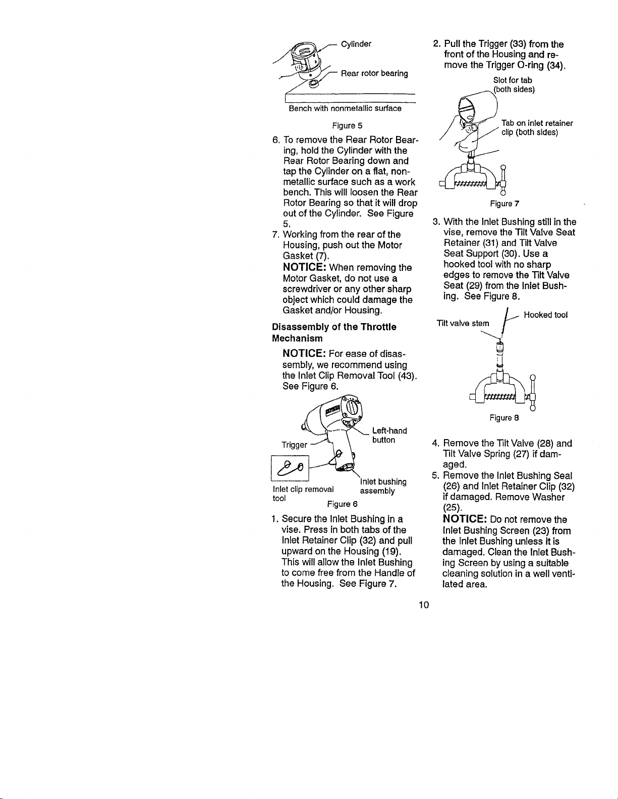
Rear rotor bearing
_ Cylinder
Bench with nonmetallic surface
Figure 5
6. To remove the Rear Rotor Bear-
ing, hold the Cylinder with the
Rear Rotor Bearing down and
tap the Cylinder on a flat, non-
metallic surface such as a work
bench. This will loosen the Rear
Rotor Bearing so that it will drop
out of the Cylinder. See Figure
5.
7. Working from the rear of the
Housing, push out the Motor
Gasket (7).
NOTICE: When removing the
Motor Gasket, do not use a
screwdriver or any other sharp
object which could damage the
Gasket and/or Housing.
Disassembly of the Throttle
Mechanism
NOTICE: For ease of disas-
sembly, we recommend using
the inlet Clip Removal Tool (43).
See Figure 6.
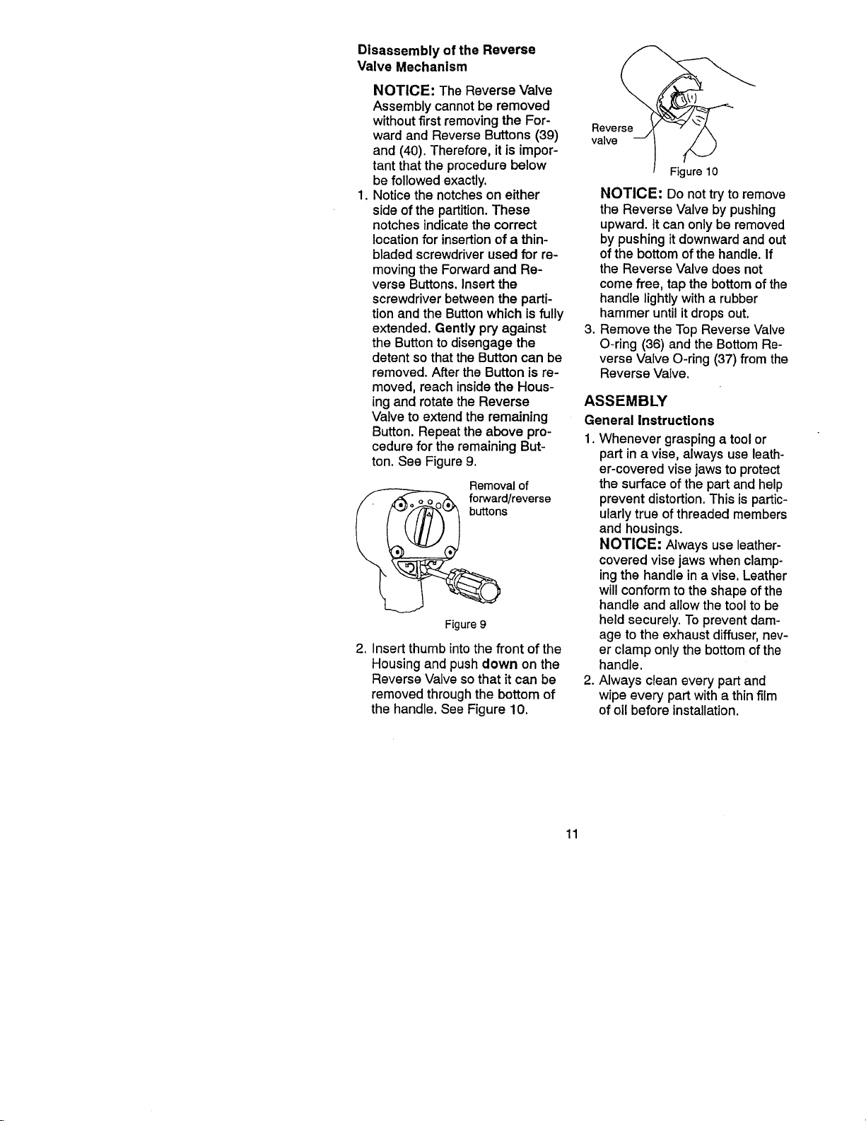
2. Pull the Trigger (33) from the
front of the Housing and re-
move the Trigger O-ring (34).
SIotfortab
Tab on inlet retainer
clip (both sides)
Figure 7
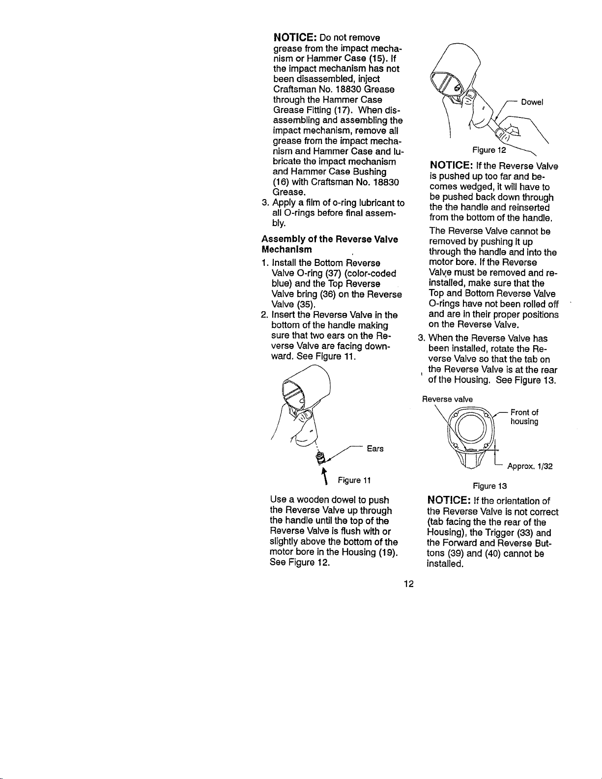
3. With the Inlet Bushing stillinthe
vise, remove the Tilt Valve Seat
Retainer (31) and Tilt Valve
Seat Support (30). Use a
hooked tool with no sharp
edges to remove the Tilt Valve
Seat (29) from the Inlet Bush-
ing. See Figure 8.
Hooked tool
Tilt valve stem
Left-hand
button
Inlet clip removal assembly
tool
Figure 6
Inlet bushing
1. Secure the Inlet Bushing in a
vise. Press in both tabs of the
Inlet Retainer Clip (32) and pull
upward on the Housing (19).
This will allow the Inlet Bushing
to come free from the Handle of
the Housing. See Figure 7.
Figure 8
.
Remove the TiltValve (28) and
-lilt Valve Spring (27) if dam-
aged.
5°
Remove the inlet Bushing Seal
(26) and Inlet Retainer Clip (32)
if damaged. Remove Washer
(25).
NOTICE: Do not remove the
Inlet Bushing Screen (23) from
the Inlet Bushing unless it is
damaged. Cleanthe Inlet Bush-
ing Screen by using a suitable
cleaning solution in a well venti-
lated area.
10
Disassembly of the Reverse
Valve Mechanism
NOTICE: The Reverse Valve
Assembly cannot be removed
without first removing the For-
ward and Reverse Buttons (39) valve
and (40). Therefore, it is impor-
tant that the procedure below
be followed exactly.
1. Notice the notches on either
side of the partition. These
notches indicate the correct
location for insertion of a thin-
bladed screwdriver used for re-
moving the Forward and Re-
verse Buttons. Insert the
screwdriver between the parti-
tion and the Button which is fully
extended. Gently pry against 3.
the Button to disengage the
detent so that the Button can be
removed. After the Button is re-
moved, reach inside the Hous-
ing and rotate the Reverse
Valve to extend the remaining
Button. Repeat the above pro-
cedure for the remaining But-
ton. See Figure 9.
Removal of
_ _°uttrWoard/reverse
Figure 9
2. Insert thumb into the front of the
Housing and push down on the
Reverse Valve so that it can be
removed through the bottom of
the handle. SeeFigure 10.
Reverse
Figure 10
NOTICE: Do not try to remove
the Reverse Valve by pushing
upward. It can only be removed
by pushing it downward and out
of the bottom of the handle. If
the Reverse Valve does not
come free, tap the bottom of the
handle lightly with a rubber
hammer until it drops out.
Remove the Top Reverse Valve
O-ring (36) and the Bottom Re-
verse Valve O-ring (37) from the
Reverse Valve.
ASSEMBLY
General Instructions
1. Whenever grasping a tool or
part in a vise, always use leath-
er-covered vise jaws to protect
the surface ofthe part and help
prevent distortion.This ispartic-
ularlytrue of threadedmembers
and housings.
NOTICE: Always use leather-
covered visejaws when clamp-
ingthe handle ina vise, Leather
willconformto the shapeofthe
handle and allowthetoolto be
heldsecurely.To prevent dam-
age to the exhaust diffuser, nev-
er clamp only the bottom of the
handle.
2. Always clean every part and
wipe every part with a thin film
of oil before installation.
11
NOTICE: Do not remove
grease from the impactmecha-
nismor Hammer Case (15). If
the impactmechanism has not
been disassembled,inject
Craftsman No. 18830 Grease
throughthe Hammer Case
Grease Fitting(17). When dis-
assemblingand assemblingthe
impactmechanism,remove all
grease from the impactmecha-
nism and Hammer Case and lu-
bricatethe impactmechanism
and Hammer Case Bushing
(16) with Craftsman No. 18830
Grease.
3. Apply a filmof o-ringlubricantto
all O-rings beforefinal assem-
bly.
Assembly of the Reverse Valve
Mechanism
1. Install the Bottom Reverse
Valve O-ring (37) (color-coded
blue) and theTop Reverse
Valve bring(36) on the Reverse
Valve (35).
2. Insert the ReverseValve in the
bottomof the handlemaking
sure thattwoears on the Re-
verseValve are facing down-
ward.See Figure 11.
Dowel
Figure12
NOTICE: If the Reverse Valve
is pushed up too far and be-
comes wedged, itwillhave to
be pushed backdownthrough
the the handleand reinserted
from the bottomof the handle.
The Reverse Valve cannot be
removed by pushing it up
through the handle and into the
motor bore. If the Reverse
Valve must be removed and re-
installed, make sure that the
Top and Bottom Reverse Valve
O-rings have not been rolled off
and are in their proper positions
on the Reverse Valve.
3. When the Reverse Valve has
been installed, rotate the Re-
verse Valve so that the tab on
the Reverse Valve is at the rear
I
of the Housing. See Figure 13.
/_ Ears
Figure 11
Use a wooden dowel to push
the Reverse Valve up through
the handle until the top of the
Reverse Valve is flush with or
slightly above the bottom of the
motor bore in the Housing (19).
See Figure 12.
Reverse valve
housing
__ Front of
Approx, 1/32
Figure13
NOTICE: !f the orientation of
the Reverse Valve is not correct
(tab facing the the rear of the
Housing), the Trigger (33) and
the Forward and Reverse But-
tons (39) and (40) cannot be
installed.
12
 Loading...