

Craftsman 235.185930 Owner's Manual
Owner ’s Manual
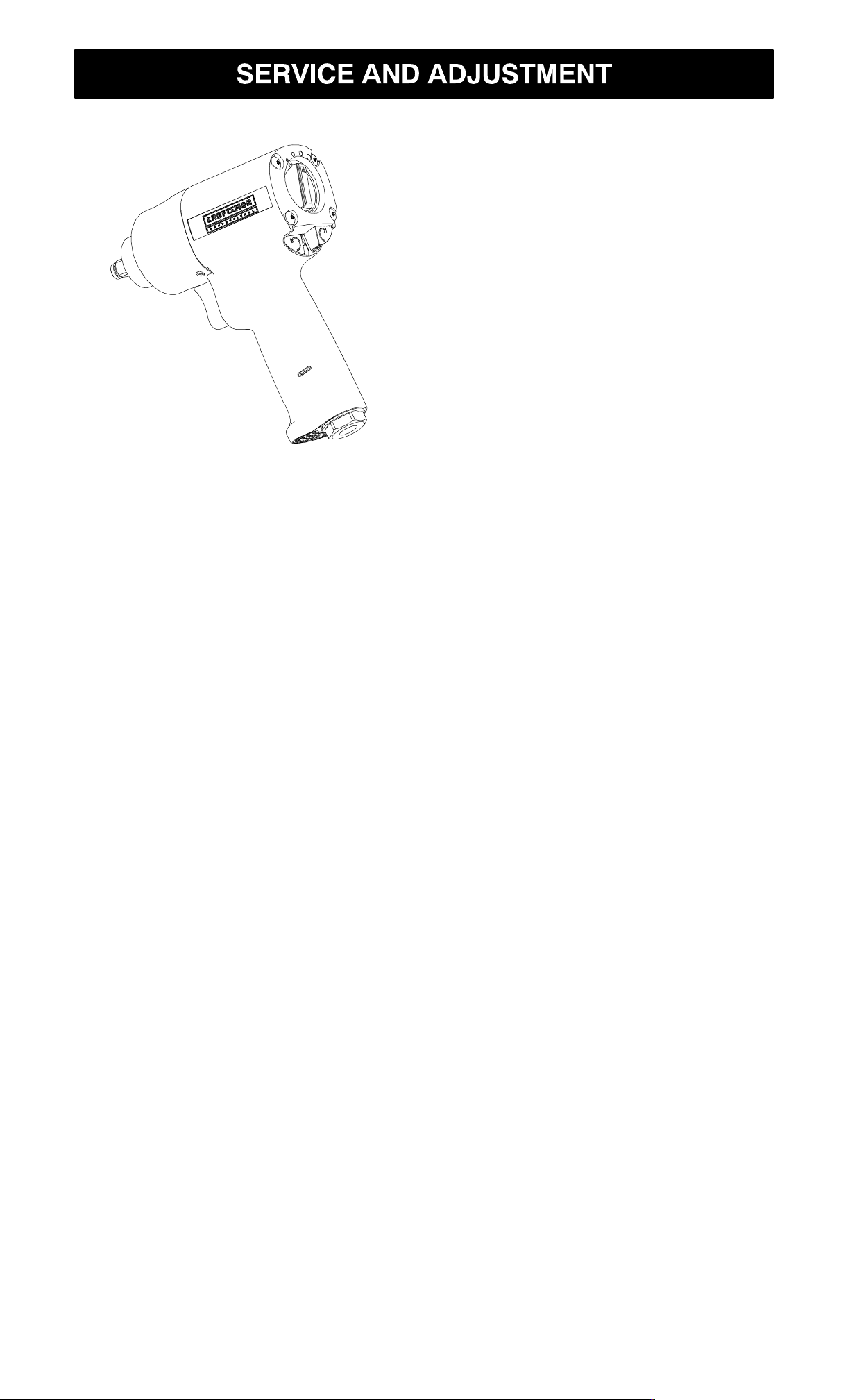
3/4¨ Drive Ultra–Duty
PISTOL GRIP IMPACT WRENCH
Model No.
235.185930
WARNING:
Before using this Impact Wrench
read this manual and follow all its
S Safety
S Operation
S Maintenance
S Service and
Adjustments
S Parts List
S Español
Safety and Operating Instructions.
Sears, Roebuck and Co., Hoffman Estates, IL 60179
Owner’s Manual P7463 (09–00) Printed in USA

TABLE OF CONTENTS PAGE
Two Year Warranty 2
Safety 3–5
Warning Labels
Notice, Warning and Caution
Placing Tool In Service
Using the Tool
Operation 6–7
Air Supply and Connections
Using the Power Management System
Specifications
Maintenance 7
Lubrication
Service and Adjustment 8–15
Disassembly
Assembly
Troubleshooting 16
Parts List 17–19
Exploded Drawing
Parts for Ordering
Español 20–37
FULL TWO YEAR WARRANTY
If this product fails due to a defect in material or workmanship within
two years from the date of purchase, Sears will at its option, repair or
replace it free of charge.
Return this product to a Sears Service Center for repair, or to place of
purchase for replacement.
This warranty gives you specific legal rights, and you may also have
other rights which vary from state to state.
Sears, Roebuck and Co., Dept. 817WA, Hoffman Estates, IL 60179
2
WARNING
WARNING
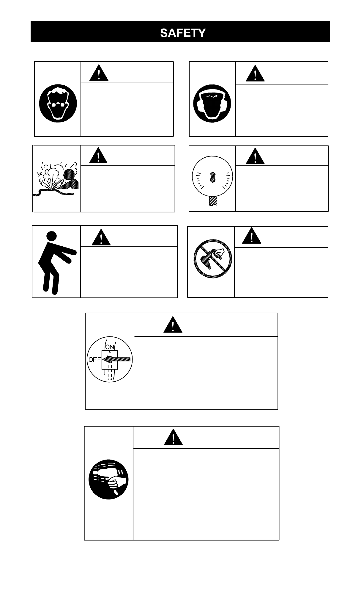
Always wear eye
protection when operating or performing maintenance on
this tool.
WARNING
Do not use damaged, frayed or
deteriorated air
hoses and fittings.
WARNING
Keep body stance
balanced and firm.
Do not overreach
when operating this
tool.
90 psig
(6.2bar/620kPa)
Always wear hearing protection
when operating
this tool.
WARNING
Operate at 90 psig
(6.2 bar/620 kPa)
Maximum air
pressure.
WARNING
Do not carry the
tool by the hose.
WARNING
Always turn off the air supply
and disconnect the air supply
hose before installing, removing or adjusting any accessory on this tool, or before
performing any maintenance
on this tool.
WARNING
Air powered tools can vibrate
in use. Vibration, repetitive
motions or uncomfortable
positions may be harmful to
your hands and arms. Stop
using any tool if discomfort,
tingling feeling or pain occurs.
Seek medical advice before
resuming use.
3

WARNING is used to indicate the presence of a hazard which
can cause severe personal injury or death if the warning is ignored.
CAUTION is used to indicate the presence of a hazard which will
or can cause minor personal injury or property damage if the caution is ignored.
NOTICE is used to notify people of installation, operation or main-
tenance information which is important but not hazard related.
This Craftsman Impact Wrench is
designed for use in general automotive repair, tire service and
heavy duty fleet applications.
WARNING:
Important safety information enclosed.
Read this manual before operating
tool.
It is the responsibility of an employer to place the information in
this manual into the hands of anyone who operates this device.
Failure to observe the following
warnings could result in injury.
PLACING TOOL IN SERVICE
parts, operate this tool at
90 psig (6.2 bar/620 kPa) maximum air pressure at the inlet
with 1/2” (13 mm) inside diameter air supply hose.
• Always turn off the air supply
and disconnect the air supply
hose before installing, removing
or adjusting any accessory on
this tool, or before performing
any maintenance on this tool.
• Do not use damaged, frayed or
deteriorated air hoses and fittings.
• Be sure all hoses and fittings
are the correct size and are
tightly secured. See Figure 1 for
a typical piping arrangement.
• Always operate, inspect and
maintain this tool in accordance
with all regulations (local, state,
federal and country), that may
apply to hand–held/hand–operated pneumatic tools.
• For safety, top performance,
and maximum durability of
• Always use clean, dry air at
90 psig maximum air pressure.
Dust, corrosive fumes and/or
excessive moisture can ruin the
motor of an air tool.
• Do not lubricate tools with flammable or volatile liquids such as
kerosene, diesel or jet fuel.
4

PLACING TOOL IN SERVICE
(continued)
• Do not remove any labels. Replace any damaged label.
• The use of a hose whip is recommended. A coupler connected directly to the air inlet increases tool bulk and decreases tool maneuverability.
• For maximum performance, the
coupler on the wall should be
the next size larger than the
coupler used on the tool. The
coupler closest to the tool
should not be less than the
proper air supply hose size.
• Tool shaft may continue to rotate briefly after throttle is released.
• Air powered tools can vibrate in
use. Vibration, repetitive motions or uncomfortable positions
may be harmful to your hands
and arms. Stop using any tool if
discomfort, tingling feeling or
pain occurs. Seek medical advice before resuming use.
• Use accessories recommended
by Craftsman.
• Use only impact sockets and
accessories. Do not use hand
(chrome) sockets or accessories.
USING THE TOOL
• Always wear eye protection
when operating or performing
maintenance on this tool.
• Always wear hearing protection
when operating this tool.
• Keep hands, loose clothing and
long hair away from rotating
end of tool.
• Note the position of the reversing button or mechanism before
operating the tool to be aware
of the direction of rotation when
operating the throttle.
• Anticipate and be alert for sudden changes in motion during
start–up and operation of any
power tool.
• Keep body stance balanced
and firm. Do not overreach
• Impact wrenches are not torque
wrenches. Connections requiring specific torque must be
checked with a torque meter after fitting with an impact
wrench.
• This tool is not designed for
working in explosive atmospheres.
• This tool is not insulated against
electric shock.
NOTICE: The use of other than
genuine Craftsman replacement
parts may result in safety hazards,
decreased tool performance, increased maintenance, and may
invalidate all warranties.
Repairs should be made only by
authorized trained personnel.
when operating this tool. High
reaction torques can occur at or
below the recommended air
pressure.
5
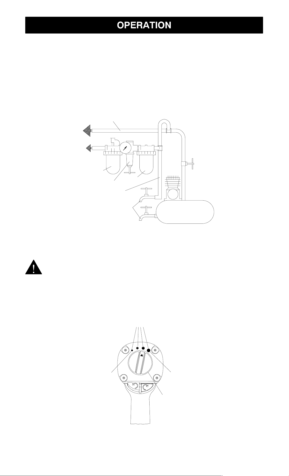
Air Supply and Connections
Always use clean dry air. Dust,
corrosive fumes and/or excessive
moisture can ruin the motor of an
increase the life of an air tool. The
filter removes dust and moisture.
Be sure all hoses and fittings are
the correct size and are tightly secured. See Figure 1 for a typical
air tool. An air line filter can greatly
Main lines 3 times air tool inlet size.
To air system
To air tool
Lubricator
Regulator
Branch line 2 times air
tool inlet size
Drain regularly
Filter
piping arrangement.
Compressor
Figure 1
USING THE POWER MANAGEMENT SYSTEM
WARNING:
Air wrenches are not torque control devices. Fasteners with specific torque requirements must be
MODEL 185930 POWER MANAGEMENT SYSTEM
Power setting indicators
checked with suitable torque measuring devices after installation
with an air wrench.
Minimum
Maximum
Power management dial
Figure 2
6
Your Impact Wrench incorporates
ence only and DO NOT denote a
a Power Management System that
allows you to select four power
output settings. These settings
range from minimum power output
through maximum power output in
the forward direction only. The Air
Wrench will always operate at
maximum power output in the reverse direction, no matter what
power output level is selected.
NOTICE: The four power setting
indicators of increasing size on the
rear of the housing are for refer-
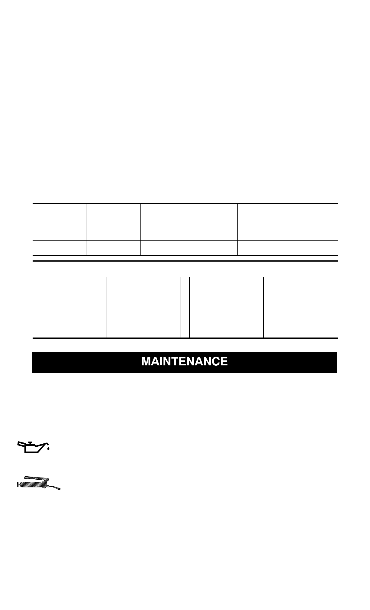
SPECIFICATIONS
Model Type of
Drive Impacts
specific power output. The small-
est power setting indicator desig-
nates minimum power output, the
two middle power setting indica-
tors denote medium power outputs
and the largest power setting indi-
cator denotes maximum power
output.
The power output can be further
reduced in forward or reverse by
using the variable throttle. Air sup-
ply systems which do not deliver
adequate air pressure can affect
power output at all settings.
Free
Weight
Handle
185930 pistol grip 3/4¨ 1,175 8,000 7 lbs.
Recommended Torque Range
Forward
lb–ft
200–900
(1100 max.)
Forward
Newton
meter (Nm)
271–1220
(1492 max.)
per min.
Reverse
lb–ft
200–900
(1200 max.)
Speed
rpm
Reverse
Newton
meter (Nm)
271–1220
(1627 max.)
LUBRICATION
Use Craftsman No. 18830
Pneumatic Tool Care Kit or a good
quality SAE 20 or 20W motor oil.
Craftsman 18830 Oil
Craftsman 18830 Grease
for routine external lubrication of the impact mechanism through the Hammer
Case Grease Fitting.
Always use an air line lubricator
with these tools.
CAUTION: Do not mark any
nonmetallic surface on this tool
with customer identification codes.
Such actions could affect tool per-
formance.
7
DISASSEMBLY
Disassembly of the Impact
Wrench
1. Clamp the handle of the impact
wrench in a vise with leathercovered jaws with the square
driver positioned horizontally.
NOTICE: Avoid excessive
clamping pressure which can
damage the Housing and can
cause difficulty when removing
the parts.
2. Unscrew and remove the four
Hammer Case Screws (12).
NOTICE: Numbers in paren-
theses in the following instructons are part illustration numbers found on pages 17-19.
General Instructions
1. Do not disassemble the tool any
further than necessary to replace or repair damaged parts.
2. Whenever grasping a tool or
part in a vise, always use leather-covered vise jaws to protect the surface of the part and
help prevent distortion. This is
particularly true of threaded
members and housings.
NOTICE: Always use lea-
3. While lightly tapping on the end
of the Anvil (9) with a plastic
hammer, lift off the Hammer
Case (16) and Hammer Case
Gasket (19).
NOTICE: The Front End Plate
(2) might come off during the
removal of the Hammer Case.
Make sure that it does not drop
on the floor or strike a hard or
metallic surface since it might
be damaged.
4. Grasp the Hammer Frame (13)
and carefully lift off the entire
impact mechanism, making certain not to drop the two Hammer Pins (14).
ther-covered vise jaws when
clamping the handle in a vise.
Leather will conform to the
shape of the handle and allow
the tool to be held securely. To
prevent damage to the exhaust
diffuser, never clamp only the
bottom of the handle.
3. Do not remove any part which
is a press fit in or on a subassembly unless the removal of
that part is necessary for repairs or replacement.
4. Do not disassemble the tool
unless you have a complete set
of new gaskets and O-rings for
replacement.
Disassembly of the Impact
Mechanism
1. Set the mechanism, driver end
up, on the workbench.
NOTICE: Note the twin ham-
mers within the Hammer
Frame. These are identical, but
must be placed in the Hammer
Frame in a certain relationship.
Using a felt-tipped pen, mark
the top hammer “T↑” and the
bottom hammer “B↑” with the
arrows pointing upward. Mark
both Hammers on the same
end.
8

2. With the mechanism sitting up-
Cylinder (1). Remove the Power
right on the workbench, slowly
rotate the Anvil in a clockwise
direction until it comes up solid.
NOTICE: If you continue to ro-
tate the Anvil, it will cam the
Hammers out of engagement.
Don’t do this; merely rotate the
Anvil until it comes up solid.
3. Hold the Hammer Frame firmly
and without disturbing the hammers, gently lift the Anvil while
simultaneously rotating it clockwise about 1/8 of a turn from
the Hammer Frame.
4. With the Anvil removed, lift out
the two Hammer Pins.
NOTICE: The twin hammers
are now free to slide from the
Hammer Frame. Be careful do
not to drop them.
Disassembly of the Motor
Management Dial Seal (42) if it
needs to be replaced.
3. Remove the Front End Plate (2)
from the Cylinder by tapping the
splined end of the Rotor (6) with
a plastic hammer. If the Front
End Plate does not come loose,
secure a center punch in a vise
with the point angled downward
and outward from the vise.
Then, grasp the Cylinder and
Front End Plate in one hand
and position the hole in the end
of the Rotor against the punch.
NOTICE: Be careful not to
drop the Cylinder since it can
be damaged by hitting a hard
surface.
Using the other hand, tap the
punch with a hammer while
pressing the Rotor against the
punch. After a few taps, the
NOTICE: When pulling, disas-
sembling or assembling the motor, we recommend replacement of the Motor Gasket (8).
1. Remove the Motor Assembly
from the Housing (20) by pushing on Power Management Dial
(41) from the back of the
Housing. See Figure 3.
Power
Management
Dial
Front End Plate will slide off of
the Cylinder.
NOTICE: To prevent damage
to the Cylinder, do not tap or
strike Cylinder on a hard or metallic surface when removing
the Rotor Bearings (3) and (4).
4. To remove the Front Rotor
Bearing, hold the Front End
Plate with Front Rotor Bearing
down and tap the Front End
Plate on a flat, nonmetallic
surface such as a work bench.
This will loosen the Front Rotor
Bearing so that it will drop out of
the Front End Plate. See
Figure 4.
Figure 3
NOTICE: If the Motor Assem-
bly cannot be removed from the
Housing by pushing, tap the
Power Management Dial lightly
until the Motor Assembly is free.
2. Remove the Power Management Dial from the rear of the
Front End Plate
Front Rotor Bearing
Bench with nonmetallic surface
Figure 4
5. Remove the Rear Rotor Bearing Retainer (7) from the rear of
the Rotor (6). The Rotor can
9
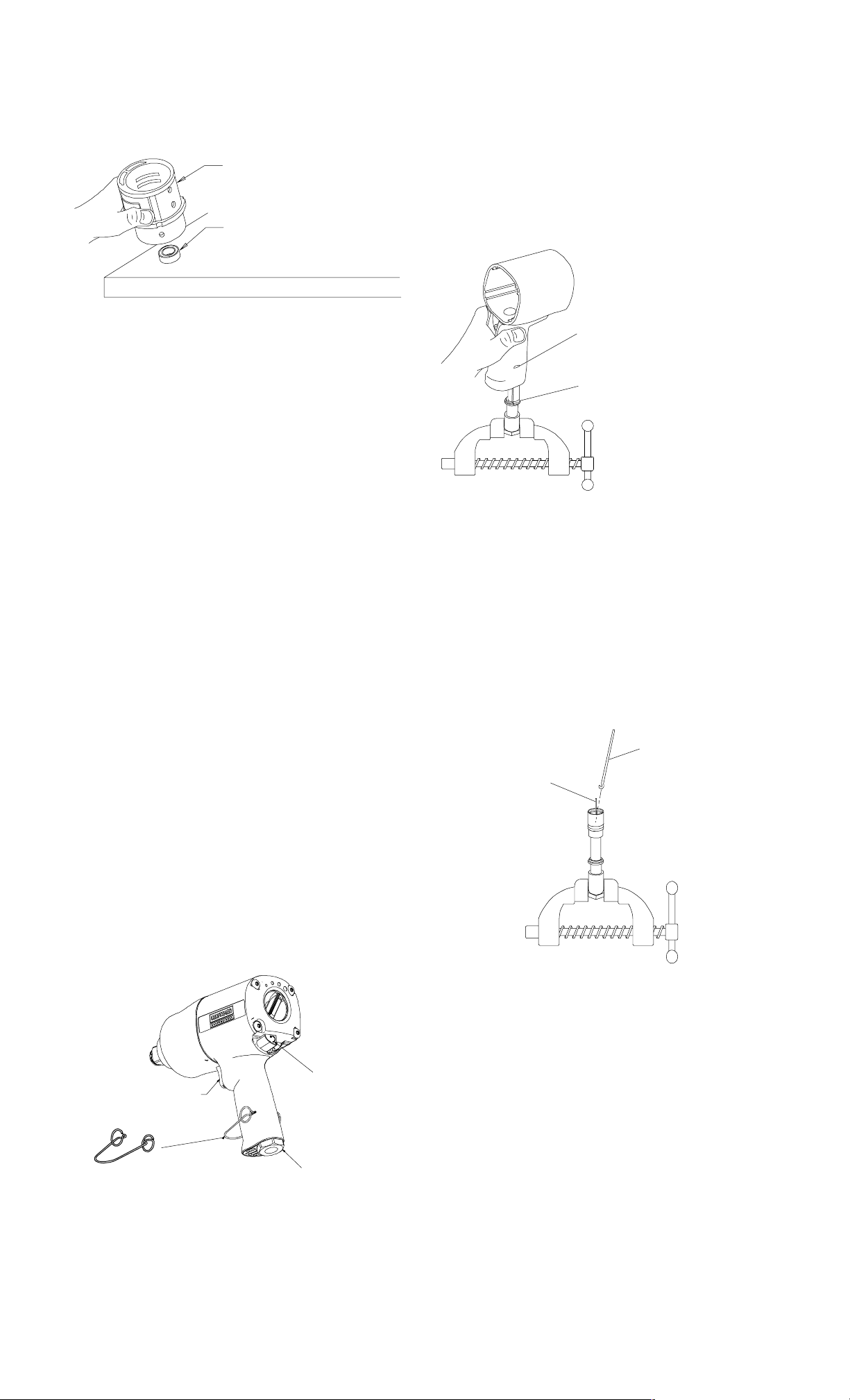
now be removed from the Cylin-
Inlet Retainer Clip (25) and pull
der. Remove the Vanes (5) from
the Rotor if they need to be replaced.
Cylinder
Rear Rotor Bearing
Bench with nonmetallic surface
Figure 5
6. To remove the Rear Rotor Bearing, hold the Cylinder with the
Rear Rotor Bearing down and
tap the Cylinder on a flat, nonmetallic surface such as a work
upward on the Housing (20).
This will allow the Inlet Bushing
to come free from the Handle of
the Housing. See Figure 7.
2. Pull the Trigger (33) from the
front of the Housing and remove the Trigger O-ring (34).
Slot for Tab
(both sides)
Tab on Inlet Retainer
Clip (both sides)
bench. This will loosen the Rear
Rotor Bearing so that it will drop
out of the Cylinder. See Figure
5.
7. Working from the rear of the
Housing, push out the Motor
Gasket (8).
NOTICE: When removing the
Motor Gasket, do not use a
screwdriver or any other sharp
object which could damage the
Gasket and/or Housing.
Disassembly of the Throttle
Mechanism
NOTICE: For ease of disas-
sembly, we recommend using
Figure 7
3. With the Inlet Bushing still in the
vise, remove the Tilt Valve Seat
Retainer (32) and Tilt Valve
Seat Support (31). Use a
hooked tool with no sharp
edges to remove the Tilt Valve
Seat (30) from the Inlet Bushing. See Figure 8.
Hooked tool
Tilt Valve stem
the Inlet Clip Removal Tool (43).
See Figure 6.
Trigger
Inlet Clip Removal
Tool
Figure 6
Left-hand
button
Inlet Bushing
Assembly
1. Secure the Inlet Bushing in a
vise. Press in both tabs of the
Figure 8
4. Remove the Tilt Valve (29) and
Tilt Valve Spring (28) if damaged.
5. Remove the Inlet Bushing Seal
(27) and Inlet Retainer Clip (25)
if damaged.
NOTICE: Do not remove the
Inlet Bushing Screen (24) from
the Inlet Bushing unless it is
damaged. Clean the Inlet Bushing Screen by using a suitable
cleaning solution in a well ventilated area.
10
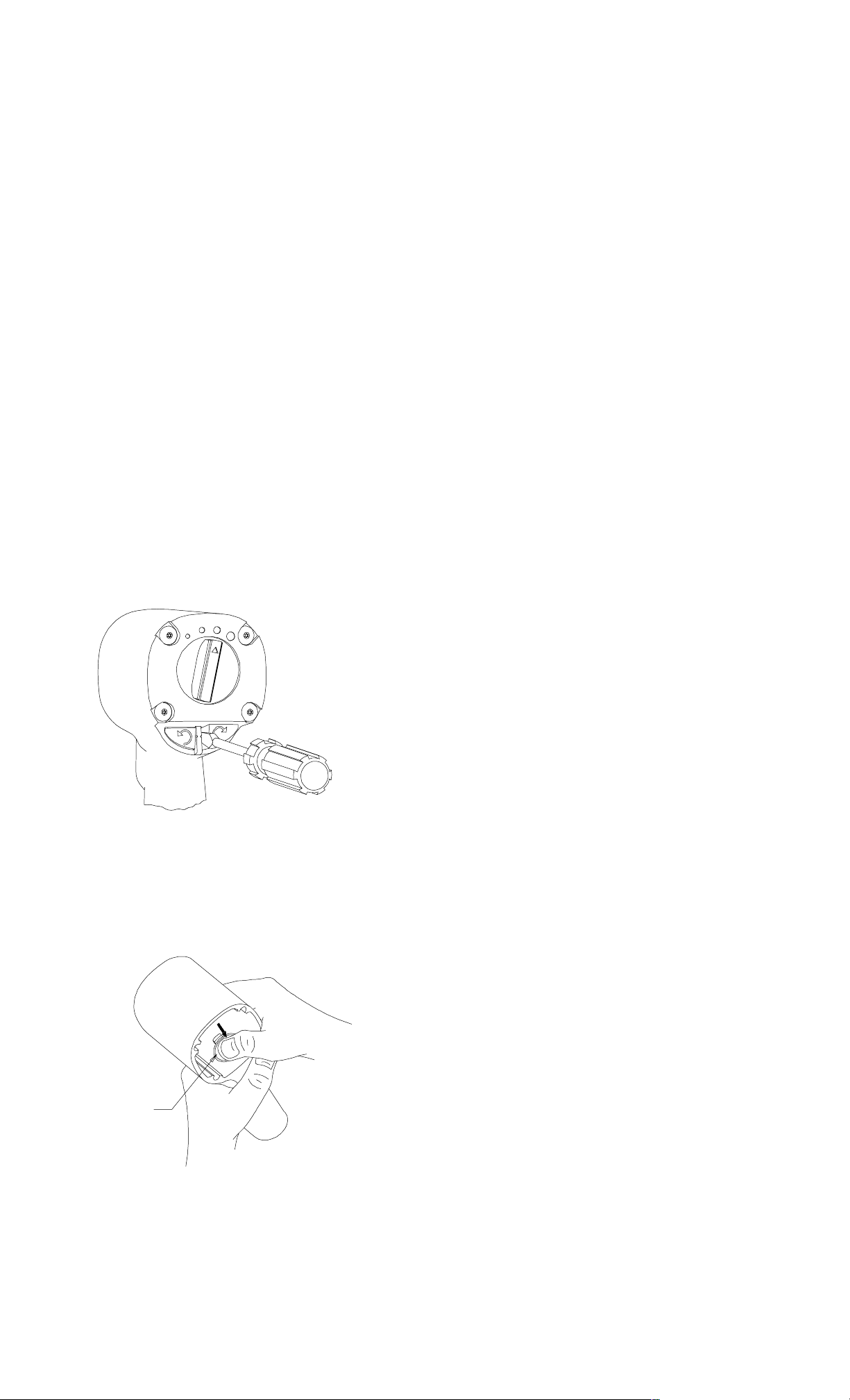
Disassembly of the Reverse
of the bottom of the handle. If
Valve Mechanism
NOTICE: The Reverse Valve
Assembly cannot be removed
without first removing the Forward and Reverse Buttons (39)
and (40). Therefore, it is important that the procedure below
be followed exactly.
1. Insert the screwdriver between
the partition and the fully extended Button. Gently pry
against the Button to disengage
the detent so that the Button
can be removed. After the Button is removed, reach inside the
Housing and rotate the Reverse
Valve to extend the remaining
Button. Repeat the above procedure for the remaining Button. See Figure 9.
Removal of
forward/reverse
buttons
the Reverse Valve does not
come free, tap the bottom of the
handle lightly with a rubber
hammer until it drops out.
3. Remove the Top Reverse Valve
O-ring (36) and the Bottom Reverse Valve O-ring (37) from the
Reverse Valve.
ASSEMBLY
General Instructions
1. Whenever grasping a tool or
part in a vise, always use leather-covered vise jaws to protect
the surface of the part and help
prevent distortion. This is particularly true of threaded members
and housings.
NOTICE: Always use leather-
covered vise jaws when clamping the handle in a vise. Leather
will conform to the shape of the
Figure 9
2. Insert thumb into the front of the
Housing and push down on the
Reverse Valve so that it can be
removed through the bottom of
the handle. See Figure 10.
handle and allow the tool to be
held securely. To prevent damage to the exhaust diffuser, never clamp only the bottom of the
handle.
2. Always clean every part and
wipe every part with a thin film
of oil before installation.
NOTICE: Do not remove
grease from the impact mechanism or Hammer Case (16). If
the impact mechanism has not
been disassembled, inject
Craftsman No. 18830 Grease
through the Hammer Case
Grease Fitting (18). When disassembling and assembling the
Reverse
Valve
Figure 10
NOTICE: Do not try to remove
the Reverse Valve by pushing
upward. It can only be removed
by pushing it downward and out
impact mechanism, remove all
grease from the impact mechanism and Hammer Case and lubricate the impact mechanism
and Hammer Case Bushing
(17) with Craftsman No. 18830
Grease.
3. Apply a film of o-ring lubricant to
all O-rings before final assembly.
11
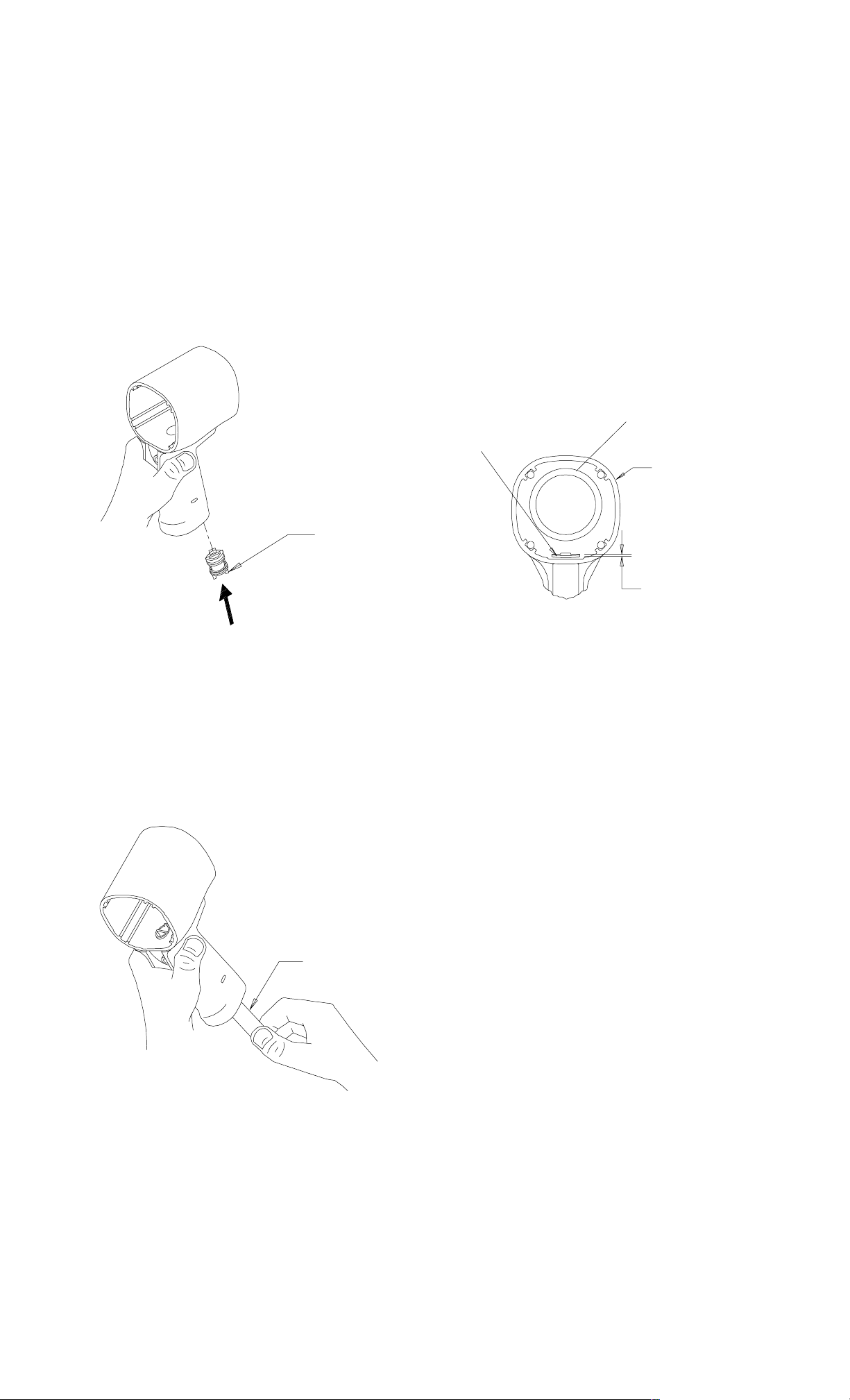
Assembly of the Reverse Valve
The Reverse Valve cannot be
Mechanism
1. Install the Bottom Reverse
Valve O-ring (37) (color-coded
blue) and the Top Reverse
Valve O–ring (36) on the Reverse Valve (35).
2. Insert the Reverse Valve in the
bottom of the handle making
sure that two ears on the Reverse Valve are facing downward. See Figure 11.
removed by pushing it up
through the handle and into the
motor bore. If the Reverse
Valve must be removed and reinstalled, make sure that the
Top and Bottom Reverse Valve
O-rings have not been rolled off
and are in their proper positions
on the Reverse Valve.
3. When the Reverse Valve has
been installed, rotate it so that
the tab is at the rear of the
Housing. See Figure 13.
Rear of Housing
Reverse Valve
Front of
Housing
Ears
Figure 11
Use a wooden dowel to push
the Reverse Valve up through
the handle until the top of the
Reverse Valve is flush with or
slightly above the bottom of the
motor bore in the Housing (20).
See Figure 12.
Approx. 1/32”
Figure 13
NOTICE: If the orientation of
the Reverse Valve is not correct
(tab facing the the rear of the
Housing), the Trigger (33) and
the Forward and Reverse Buttons (39) and (40) cannot be
installed.
4. Install the Trigger O-ring (34) on
the Trigger. Insert the Trigger
Assembly in the front of the
Housing.
5. Rotate the Reverse Valve in ei-
Dowel
Figure 12
NOTICE: If the Reverse Valve
is pushed up too far and becomes wedged, it will have to
be pushed back down through
the the handle and reinserted
from the bottom of the handle.
ther direction until an ear comes
up against the Trigger.
6. Look through the Housing from
the rear. If the tab on the Re-
verse Valve has been rotated to
the left, install the right Button
in the Housing. When one Button has been installed, push the
Button in. This will rotate the’
Reverse Valve so that the other
Button can be installed. See
Figure 14.
12
 Loading...