

Craftsman 226165291 Owner’s Manual
Operator's Manual
[RRFTSMRN°
Permanently Lubricated
Tank Mounted
AIR COMPRESSOR
Model No.
226.165291
CAUTION: Read and follow
all Safety Rules and Operating
Instructions before First Use
of this Product.
Sears, Roebuck and Co., Hoffman Estates, IL 60179LU _
17939.02 Draft (06/19/02)
• Safety Rules
• Operation
• Maintenance
• Parts List
Warranty ....................................... 2
Safety Rules .................................... 2
Glossary ..................................... 2-3
Installation.................................... 3-4
Operation .................................... 4-6
Maintenance .................................. 6-7
Storage ....................................... 7
Troubleshooting ................................ 8-9
Parts Illustration and List ....................... 10-11
FULL ONE YEAR WARRANTY ON CRAFTSMAN
AIR COMPRESSOR
Ifthis Craftsman air compressorfalls due to a defect in materi-
al or workmanship within one full year from the date of pur-
chase, return it to the nearest Sears Service Center in the
United States, and Sears will repair it free of charge.
If this air compressor is used for commercial purposes, this
warranty applies for only 90 days from the date of purchase.
This warranty gives you specific legal rights and you may also
have other rights which vary from state to state.
Sears, Roebuck and Co., Dept. 817WA, Hoffman Estates, IL
60179
WARNING: For your own safety read all of the instructions
and precautions before operating tool.
CAUTION: Always follow proper operating procedures as
defined in this manual even if you are familiar with use of this
or similar tools. Remember that being careless for even a
fraction of a second can result in severe personal injury.
• Always operate the compressor in a well ventilated area
free of combustible materials, gasoline or solvent vapors.
• If spraying flammable materials, locate compressor at least
20 feet away from spray area. An additional length of hose
may be required. Store flammable materials in a secure
location away from compressor.
• Never place objects against or on top of compressor.
Operate compressor in an open area at least 12 inches
away from any wall or obstruction that would restrict the
flow of fresh air to the ventilation openings,
• Operate compressor is a clean, dry, well ventilated area.
Do not operate unit indoors or in any confined area.
• Always remain in attendance with the product when it is
operating.
• Drain tank daily or after each use. If tank develops a leak,
replace it immediately with a new tank or replace the
entire compressor.
• Never drill into, weld or make any modifications to the tank
or its attachments.
• The tank is designed to withstand specific operating pres-
sures. Never make adjustments or parts substitutions to
alter the factory set operating pressures.
• For essential control of air pressure, you must install a
pressure regulator and pressure gauge to the air outlet (if
not equipped) of your compressor. Follow the equipment
manufacturers recommendation and never exceed the
maximum allowable pressure rating of attachments. Never
use compressor to inflate small low-pressure objects such
as children's toys, footballs, basketballs, etc.
Always wear ANSI Z87.1 approved safety glasses with
side shields when using the compressor.
Never point any nozzle or sprayer toward any part of the
body or at other people or animals.
Always turn the compressor off and bleed pressure from
the air hose and tank before attempting maintenance,
attaching tools or accessories.
Never operate the compressor outdoors when it is raining
or in wet conditions.
Never operate compressor with protective covers removed
or damaged.
Any electrical wiring or repairs required on this product
should be performed by authorized service center person-
nel in accordance with national and local electrical codes.
• Make certain that the electrical circuit to which the com-
pressor is connected provides proper electrical grounding,
correct voltage and adequate fuse protection.
Air obtained directly from the compressor should never be
used to supply air for human consumption, in order to use
air produced by this compressor for breathing, suitable fil-
ters and in-line safety equipment must be properly
installed. In-line filters and safety equipment used in con-
junction with the compressor must be capable of treating
air to all applicable local and federal codes prior to human
consumption.
• Work in an area with good cross-ventilation. Read and fol-
low the safety instructions provided on the label or safety
data sheets for the material you are spraying. Use a
NIOSH/MSHA approved respirator designed for use with
your specific application.
• Never touch any exposed metal parts on compressor dur-
ing or immediately after operation. Compressor will remain
hot for several minutes after operation.
Do not reach around protective shrouds or attempt mainte-
nance until unit has been allowed to cool.
Always operate compressor in a stable secure position to
prevent accidental movement of the unit. Never operate
compressor on a roof or other elevated position. Use addi-
tional air hose to reach high locations.
Become familiar with these terms before operating the unit.
CFM: Cubic feet per minute.
SCFM: Standard cubic feet per minute; a unit of measure of
air delivery.
PSIG: Pounds per square inch gauge; a unit of measure of
pressure.
Code Certification: Products that bear one or more of the
following marks: UL, CUL, ETL, CETL, have been evaluated
by OSHA certified independent safety laboratories and meet
the applicable Underwriters Laboratories Standards for Safety.
Cut-In Pressure: While the motor is off, air tank pressure
drops as you continue to use your accessory.When the tank
pressure drops to a certain low level the motor will restart
automatically,The low pressure at whichthe motor automati-
cally restartsis called "cut-in"pressure.
2

Cut-OutPressure:Whenanaircompressoristurnedonand
begins to run, air pressure in the air tank begins to build, it
buildsto a certain high pressure before the motor automati-
cally shuts off- protecting your air tank from pressure higher
than its capacity. The high pressure at which the motorshuts
off is called "cut-out" pressure.
Branch Circuit: Cimuit carrying electricity from electrical
panel to outlet.
LOCATION OF THE AIR COMPRESSOR
Locate the air compressor in a clean, dry and well ventilated
area. The air compressor should be located at least 12" away
from the wall or other obstructions that will interfere with the
flow of air. The air compressor pump and shroud are designed
to allow for proper cooling.The ventilation openings on the
compressor are necessary to maintain proper operating tem-
perature. Do not place rags or other containers on or near
these openings.
POWER SOURCE
The motor is designed for operation on the voltage and fre-
quency specified. Normal loads will be handled safely on volt-
ages not more than 10% above or below specified voltage.
Runningthe unit on voltageswhich are not within range may
cause overheating and motor burn-out. Heavy loads require
that voltage at motor terminals be no less than the voltage
specified on nameplate.
• Air compressor requires a 115 volt, 60 Hz power source.
GROUNDING INSTRUCTIONS
WARNING: Improper connection of equipment grounding
conductor can resultin the risk of electrical shock. Equipment
should be grounded while in use to protect operator from
electrical shock.
• Check with a qualified electrician if you do not understand
grounding instructions or if you are in doubt as to whether
the tool is properly grounded,
• This tool is equipped with an approved 3-conductor cord
rated up to 240V and a 3-prong grounding type plug rated
at 115V (See Figure 1) for your protection against shock
hazards.
• Grounding plug should be plugged directly into a properly
installed and grounded 3-prong greunding-type receptacle,
as shown (See Figure 1),
Properly Grounded Outlet
Grounding Prong
3-Prong Plug _
Figure 1 - 3-Prong Receptacle
fit in outlet, have proper outlet installed by a qualified
electrician.
• Inspect tool cords periodically, and if damaged, have
repaired by an authorized service facility.
• Green (or green and yellow) conductor in cord is the
grounding wire. if repair or replacement of the electric cord
or plug is necessary, do not connect the green (or green
and yellow) wire to a live terminal.
• Where a 2-prong wall receptacle is encountered, it must
be replaced with a properly grounded 3-prong receptacle
installed in accordance with National Electric Code and
local codes and ordinances.
WARNING: Any receptacle replacement should be per-
formed bya qualified electrician.
A temporary3-prong to 2-prong grounding adapter (See
Figure2) is available for connecting plugstoa two pole outlet
if it is properly grounded.
Grounding Lug Make Sure This
Adapter \
3-Pron_. _ Greund
2-Prong Receptacle
Figure 2 - 2-Prong Receptacle with Adapter
• Do not use a 3-prong to 2-preng grounding adapter unless
permitted by local and national codes and ordinances. (A
3-preng to 2-preng grounding adapter is notpermitted in
Canada,)
• Where a 3-prong to 2-preng grounding adapter ispermit-
ted, the rigidgreen tab or terminal on the side of the
adapter must besecurely connected to a permanent elec-
trical ground such as a properly grounded water pipe, a
properly grounded outlet box or a properly grounded wire
system.
• Many cover plate screws, water pipes and outlet boxesare
not properly grounded. Toensure proper ground, ground-
ing means must be tested by a qualified electrician,
EXTENSION CORDS
• The use of any extension cord will cause some drop in
voltage and loss of power.
• Wires of the extension cord must be of sufficient size to
carry the current and maintain adequate voltage.
• Use the table to determine the minimum wire size (A.W.G.)
extension cord.
• Use only 3-wire extension cords having 3-prong grounding
type plugs and 3-pole receptacles which accept the tool
plug.
• Ifthe extension cord is worn, cut or damaged in any way,
replace itimmediately.
• Do not remove oralter grounding preng in any manner. In the
event of a malfunction or breakdown, grounding provides a
path of least resistance for electrical shock.
WARNING: Do not permit fingers to touch the terminals of
plug when installing or removing from outlet.
• Plug must be plugged into matching outlet that is properly
installed and grounded in accordance with all local codes
and ordinances. Do not modify plug provided. If it will not
EXTENSION CORD LENGTH
Wire Size A.W.G.
Up to 50 ff..................................... 12
NOTE: Using extension cords over 50 ft. long is not
recommended.
3
VOLTAGE AND CIRCUIT PROTECTION
This air compressor can be operated on a 15 amp circuit if
the following conditions are met.
• Voltage supply threugh branch circuit is 15 amps.
• Circuit is not used to supply any other electrical needs
(lights, appliances, etc.)
• Extension cords comply with specifications.
• Circuit is equipped with a 15 amp circuit breaker or 15
amp time delay fuse.
NOTE: If compressor is connected to a circuit protected by
fuses, use only time delay fuses marked "D".
If any of the above conditions cannot be met, or if operation of
the compressor repeatedly causes interruption of the power, it
may be necessary to operate it from a 20 amp circuit. It is not
necessary to change the line cord.
DESCRIPTION
The Craftsman permanently lubricated air compressor con-
sists of a one cylinder, single-stage air compressor pump and
air tank. This air compressor requires no oil.Your air compres-
sor can be used for operating paintspray guns, air tools, blow
guns, nailers/staplers, air brushes and inflator kits,An inline
are filter which removes moisture and dirt from compressed
air should be used where applicable. An inline regulator can
be used if a more precise adjustment of air pressure is need-
ed downstream.
SPECIFICATIONS
HP (Max. Developed) ............................. 2
Displacement ............................. 4.6 CFM
Bore ....................................... 1.85"
Stroke ..................................... 0.86"
Voltage-Single Phase .......................... 115 V
Minimum Branch Circuit Requirement .............. 15A.
Fuse Type ............................. Amps Delay
Air Tank Capacity .......................... 6 Gallons
Approximate Cut-In Pressure .................. 110 PSI
Approximate Cut-Out Pressure ................. 150 PSI
SCFM@40 psi ................................. 3.9
SCFM@90 psi ................................. 2.7
AIR COMPRESSOR CONTROLS
Refer to Figures 3, 4 and 5.
Become familiar with these controls before operating the unit.
• Auto/Off Lever: Turn this lever to "Auto" to provide auto-
matic power to the pressure switchand "OFF" to remove
power at the end of each use.
• Pressure Switch: The pressure switchautomatically
starts the motorwhen the air tank pressure drops below
the factoryset "cut-in"pressure.It stopsthe motor when the
airtank pressure reaches the factoryset "cut-out"pressure,
• Safety Valve: If the pressure switch does not shut off the
air compressor at its"cut-out" pressure setting,the safety
valve will protect against high pressure by "popping out"at
its factory set pressure (Slightlyhigher than the pressure
switch "cut-out" setting).
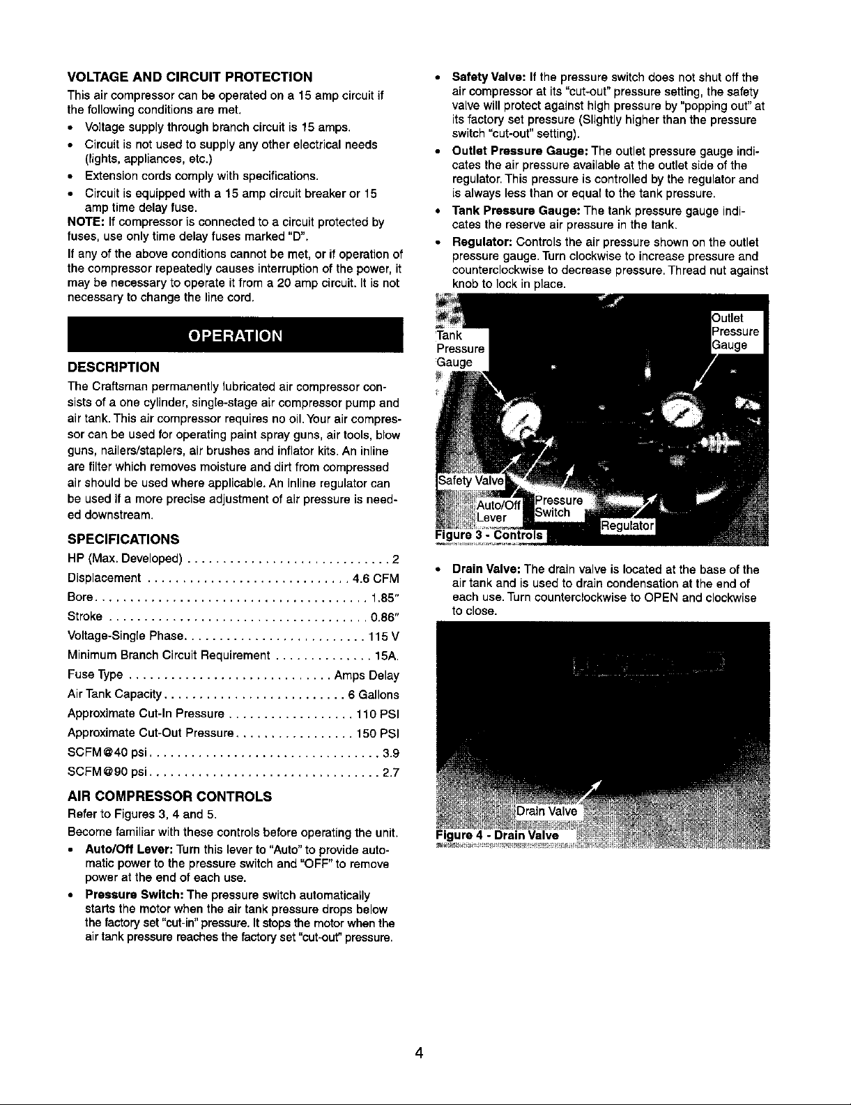
• Outlet Pressure Gauge: The outlet pressure gauge indi-
cates the air pressure available at the outlet side of the
regulator. This pressure is controlled by the regulator and
is always less than or equal to the tank pressure.
• Tank Pressure Gauge: The tank pressure gauge indi-
cates the reserve air pressure in the tank.
• Regulator: Controls the air pressure shown on the outlet
pressure gauge.Turn clockwise to increase pressure and
counterclockwiseto decrease pressure. Thread nut against
knob to lock in place.
Tank
Pressure
Gauge
Figure 3 - Controls
• Drain Valve: The drain valve is located at the base of the
air tank and is used to drain condensation at the end of
each use. Turn counterclockwise to OPEN and clockwise
to close.
Drain Valve
Figure 4 - Drain Valve
4
 Loading...