


SEARS
OWNER'S
MANUAL
MODEL NO.
225.582500
15" TRANSOM
225.582590
20" TRANSOM
CAUTION:
Read and Follow
all Safety Rules
and Instructions
Before Operating
This Equipment
Sears Roebuck and Co., Hoffman Estates, IL 60179 U.S.A.
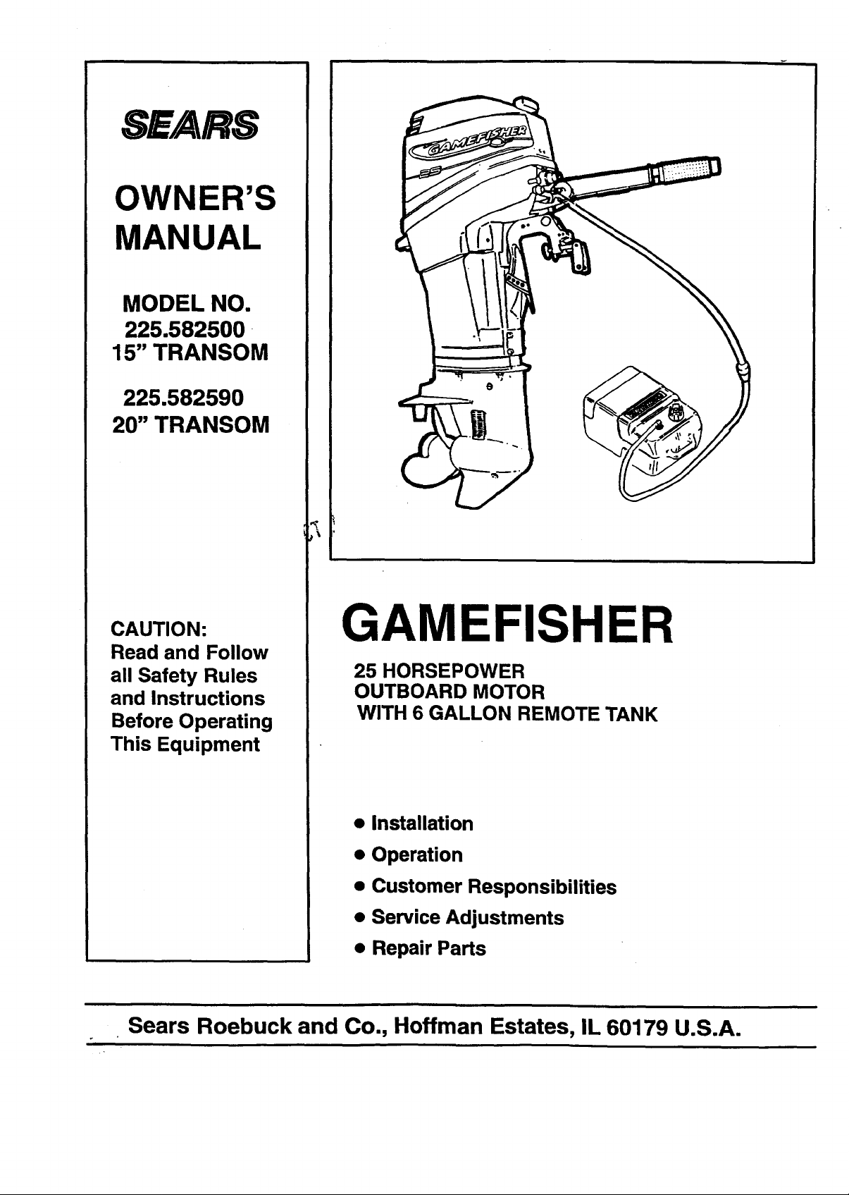
GAMEFISHER
25 HORSEPOWER
OUTBOARD MOTOR
WITH 6 GALLON REMOTE TANK
• Installation
• Operation
• Customer Responsibilities
• Service Adjustments
• Repair Parts
SAFETY & SAFE PRACTICES
Notice
Throughout this publication, "Warnings" and "Cau-
tions" (accompanied by the international HAZARD
Symbol ) are used to alert the operator to special
instructions concerning a particular operation that
may be hazardous if performed incorrectly. OB-
SERVE THEM CAREFULLY.
HAZARDS OR UNSAFE PRACTICES WHICH
COULD RESULT IN SEVERE PERSONAL
INJURY OR DEATH
HAZARDS OR UNSAFE PRACTICES WHICH
COULD RESULT IN MINOR INJURY OR
PRODUCT OR PROPERTY DAMAGE.
Boaters Responsibilities
The operator (driver) is responsible for the correct
and safe operation of the boat and safety of its occu-
pants and general public. It is strongly recommended
that each operator (driver) read and understand this
entire manual before operating the outboard.
Be sure at least one additional person is instructed in
the basics of starting and operating the outboard and
boat handling in case the driver is unable to operate
the boat.
Before Operating Your Outboard
DO NOT USE A MOTOR WITH A HORSE-
POWER RATING HIGHER THAN WHAT IS
LISTED ON THE CERTIFICATION PLATE ON
YOUR BOAT.
USING AN OUTBOARD THAT EXCEEDS THE
MAXIMUM HORSEPOWER LIMIT OF A BOAT
CAN RESULT IN SERIOUS INJURY, DEATH OR
BOAT DAMAGE.
Fuel
DO NOT STORE YOUR MOTOR OR GAS-
OLINE WHERE FUMES MAY REACH AN OPEN
FLAME AND CAUSE A FIRE.
DRAIN THE GASOLINE from your motor before
transporting your motor inside your car or other
vehicles.
• GASOLINE AND ITSVAPORS ARE EXTREME-
LY FLAMMABLE AND HIGHLY EXPLOSIVE
UNDER CERTAIN CONDITIONS, ALWAYS
STOP THE ENGINE AND DO NOT SMOKE OR
ALLOW OPEN FLAMES OR SPARKS IN THE
AREA WHILE FILLING FUEL TANK(S).
• DO NOT FILLTHE FUELTANKWHEN THE EN-
GINE IS RUNNING. DO NOT FILL THE FUEL
TANK INDOORS.
• REMOVE PORTABLE FUEL TANK FROM
BOAT WHEN REFUELING TO PREVENT SPIL-
LING FUEL IN BOAT, ALWAYS MIX FUEL IN A
WELL VENTILATED AREA.
Read this manual carefully. Learn how to operate
your outboard properly. If you have any ques-
tions, contact your nearest Sears Store which
sells Gamefisher outboard motors.
This manual as well as safety labels posted on the
outboard use safety alerts to draw your attention
to special safety instructions that should be fol-
lowed.
Safety and operating information that is practiced
along with using good common sense can help
prevent personal injury and product damage.
ALWAYS DISCONNECT SPARK PLUG WIRES AND
PLACE WIRES WHERE THEY CANNOT CONTACT
SPARK PLUGS TO PREVENT ACCIDENTAL
STARTING WHEN WORKING ON YOUR OUT-
BOARD.
Operation
DO NOT attempt to make repairs or adjustments
not specifically covered in this manual. Should
you ever need technicalassistance, please con-
tact your Sears Service Center.
NEVER OPERATE YOUR MOTOR AT FULL
THROTTLE WHEN THE ENGINE IS OVER-
LOADED. THIS CAN OCCUR-4JNDER CONDI-
TIONS WHEN A PLANING BOAT IS LOADED
SO IT DOES NOT PLANE OR WHEN TOWING
ANOTHER BOAT.
Some boats are extremely unstable in the water
even when secured to a dock. Do not stand erect.
Stay as close as possible to centerline of boat es-
pecially while installing motor.
SAFETY & SAFE PRACTICES
SERVICE
Neglected inspection and maintenance service of
your outboard or attempting to perform mainte-
nance or repair on your outboard if you are not fa-
miliar with the correct service and safety proce-
dures could cause personal injury, death or
product failure.
Using a replacement part that is inferior to the
original part could result in personal injury, death
or product failure.
Using Lanyard Stop Switch
THE PURPOSE OF THE LANYARD STOP SWITCH
IS TO TURN OFF THE ENGINE IGNITION WHEN-
EVER THE OPERATOR (WHEN AI"FACHED TOTHE
LANYARD) MOVES FAR ENOUGH AWAY FROM
THE OPERATOR'S POSITION TO ACTIVATE THE
SWITCH.
The lanyard is a cord usuallybetween 4 and 5feet
in length when stretched out with an element on
one end made to be inserted into the switchand
a clip on the other end for attaching tothe opera-
tor. It is coiled to make its at-rest condition as
short as possible so as to minimize the likelihood
of the lanyard entanglement with nearby objects.
Itis made as longas it is in itsstretched condition
to minimize the likelihood of accidental activation
should the operator choose to move around in an
area close to the normal operator's position,iffor
any reason ,it is desired to have a shorterfunc-
tionallanyard, this may be accomplishedby using
up length in the way the lanyard and clipare at-
tached to the operator (such as wrappingthe lan-
yardaround the operator's wrist orleg) orbytying
a simple knot in the lanyard.
The following advantages and disadvantages
of a lanyard stop switch should be considered
before electing to use, or not to use such a
switch.
ADVANTAGES: THE PURPOSE OF A LANYARD
STOP SWITCH IS TO STOP THE ENGINE IGNI-
TION WHENEVER THE OPERATOR (WHEN
ATTACHED TO THE LANYARD) MOVES FAR
ENOUGH AWAY FROM THE OPERATOR'S
POSITION TO ACTIVATE THE SWITCH. THIS
WOULD OCCUR IF THE OPERATOR FALLS OR
MOVES WITHIN THE BOAT A SUFFICIENT DIS-
TANCE FROM THE OPERATOR'S POSITION.
THIS TYPE OF ACCIDENT IS MOST LIKELY IN
CERTAIN TYPES OF BOATS SUCH AS LOW
SIDED BASS BOATS, HIGH PERFORMANCE
BOATS AND LIGHT, SENSITIVE-HANDLING
FISHING BOATS OPERATED BY HAND TIL-
LER. IT IS ALSO LIKELY AS A RESULT OF
POOR OPERATING PRACTICES SUCH AS SIT-
"riNG ON THE BACK OF THE SEAT AT PLAN-
ING SPEEDS, STANDING AT PLANING
SPEEDS, OPERATING AT HIGH SPEEDS IN
SHALLOW OR OBSTACLE-INFESTED WA-
TERS, RELEASING YOUR GRIP ON A STEER-
ING WHEEL THAT IS PULLING IN ONE DIREC-
TION, DRINKING AND DRIVING OR DARING,
HIGH-SPEED BOAT MANEUVERS.
DISADVANTAGES: INADVERTENT ACTIVATION
OF THE SWITCH IS A POSSIBILITY. THIS
COULD CAUSE ANY OR ALL OF THE FOL-
LOWING POTENTIALLY HAZARDOUS SITUA-
TIONS:
.
LOSS OF BALANCE AND FALLING FOR-
WARD OF UNSTABLE BOAT PAS-
SENGERS - A PARTICULAR CONCERN
IN BOW RIDER TYPE BOATS.
2. LOSS OF POWER AND DIRECTIONAL
CONTROL IN HEAVY SEAS, STRONG
CURRENT OR HIGH WINDS.
3. LOSS OF CONTROL WHEN DOCKING.
In addition, there are limitations to what the lan-
yard stop switch can do. The boat can continue
to coast for a considerable distance depending on
the velocity at shutdown and the degree of any
turn. However, the boat will not complete a full
circle while the boat iscoasting. It can cause inju-
ryto anyone in the boat's path as seriously as the
boat would when under power.
As we cannot possibly know of and advise the
boating public of all conceivable boat/motor types
and/or poor operating practices, the final decision
of whether to use a lanyard stop switch rests with
you, the owner/driver.
We strongly recommend that other occupants be
instructed on proper starting and operating proce-
dures should they be required to operate the out-
board and boat in an emergency.
-3-
CONGRATULATIONS
PRODUCT SPEClRCATIONS
You are to be congratulated on your selection of this
Outboard Motor which will give you years of satisfac-
tory service. Your Gamefisher is the end product of
years of research, engineering and development. It
has been assembled by craftsmen who take pride in
their work.
This Owner's Manual will help you to receive allthe
trouble free performance built into your motor. READ
THROUGH THIS MANUAL CAREFULLY BEFORE
OPERATING THE MOTOR. It contains complete
operating instructions and recommendations for the
care and protection of your motor. Following these
recommendations and instructions will assure you
years of boating pleasure.
Outboarding is a great sport. Always remember, how-
ever, that you have friends on the water. Extend to
them the courtesy of thoughtful, safe operation of
your motor and boat and you will increase your own
enjoyment.
MODEL
NUMBER
SERIAL
NUMBER
DATE OF
PURCHASE
THE MODEL AND SERIAL NUMBER WILL BE
FOUND ON A DECAL ATFACHED TO THE PORT
STERN BRACKET.
YOU SHOULD RECORD BOTH SERIAL NUMBER
AND DATE OF PURCHASE AND KEEP IN A SAFE
PLACE FOR FUTURE REFERENCE.
MAINTENANCE AGREEMENT
A Sears Maintenance Agreement is available on this
)roduct. Contact your nearest Sears store for details.
Engine 25 HP
Horsepower Rating @ 5500 RPM
Recommended Full Throttle
Operating Range 5000-6000 RIbM
Engine Type Two Cycle, Three Cylinder
Bore and Stroke 2.375 x 1.9375
Cubic Inch Displacement 25.75
Cooling Water Cooled
Displacement Type Water Pump
Propeller Right Hand Rotation
Spline Drive
Standard 10-3/8" Dia. x 13" Pitch
Spark Plug 33-811
(Champion L82C)
Spark Plug Gap .035 in.
Fuel Tank Remote 6.0 gal. ( 23 L)
Gear Ratio 2.25:1
No. of Teeth: Pinion Gear 12
Forward/Reverse Gear 27
Weight (approx.) 15" Leg = 921bs.
20" Leg = 951bs.
Gasoline Oil Ratio 25:1 Break- in
50:1 Normal
CUSTOMER RESPONSIBILITIES
• Read and observe the safety rules.
• Follow a regular schedule in maintaining, caring
for and usingyour outboard motor.
• Follow the instructionsunder =Customer
Responsibilities"and =Storage" sections of this
Owners Manual.
ONE YEAR LIMITED WARRANTY ON GAMEFISHER OUTBOARD MOTOR
For one year from the date of purchase, when this Gamefisher outboardmotor is maintained, lubricated and tuned-up
according to the instructionsin the owner's manual, Sears willrepair,free of Charge, any defect in material and
workmanship.
IfthisGamefisher Outboard Motor is used for commercial or rental purposes, this warranty appliesfor only90 days from
the date of purchase.
This warranty does not cover:.
• Expendable items which become wom during normaluse, such asspark plugs, water pump impeller, oil
seals, propellers and tune-ups.
• Repairs necessary because of operator abuse or negligence, including but not limitedto strikingan
underwater object and failure to maintain the equipment according to the instructionscontained in the
Owner's Manual.
WARRANTY SERVICE IS AVAILABLE BY RETURNING THE GAMEFISHER OUTBOARD MOTOR TO THE NEAR-
EST SEARS SERVICE CENTER/DEPARTMENT IN THE UNITED STATES. THIS WARRANTY APPLIES ONLY
WHILE THIS PRODUCT IS IN USE IN THE UNITED STATES.
This warranty gives you specific legal rights, and you may also have other rightswhich may vary from state to state.
Sears Roebuck and Co., Department 817WA, Hoffman Estates, IL 60179
-4-
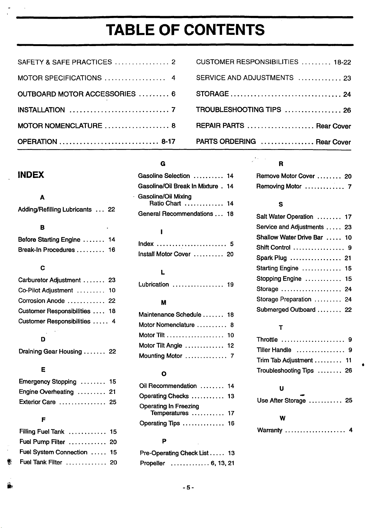
TABLE OF CONTENTS
SAFETY & SAFE PRACTICES ................ 2
MOTOR SPECIFICATIONS .................. 4
OUTBOARD MOTOR ACCESSORIES ......... 6
INSTALLATION ............................. 7
MOTOR NOMENCLATURE ................... 8
OPERATION ............................. 8-17
G
INDEX
A
Adding/Refilling Lubricants ... 22
B
Before Starting Engine ....... 14
Break-In Procedures ......... 16
C
Carburetor Adjustment ....... 23
Co-Pilot Adjustment ......... 10
Corrosion Anode ............ 22
Customer ResponsibUities .... 18
Customer Responsibilities ..... 4
D
Draining Gear Housing ....... 22
E
Emergency Stopping ........ 15
Engine Overheating ......... 21
Exterior Care ............... 25
F
Filling Fuel Tank ............ 15
Fuel Pump Filter ............ 20
Fuel System Connection ..... 15
FuelTank Filter ............. 20
Gasoline Selection .......... 14
Gasoline/Oil Break In Mixture . 14
Gasoline/Oil Mixing
Ratio Chart ............. 14
General Recommendations ... 18
I
Index ....................... 5
Install Motor Cover .......... 20
L
Lubrication ................. 19
M
Maintenance Schedule ....... 18
Motor Nomenclature .......... 8
Motor'lilt ................... 10
Motor "liltAngle ............. 12
Mounting Motor .............. 7
O
Oil Recommendation ........ 14
Operating Checks ........... 13
Operating In Freezing
Temperatures ........... 17
Operating'lips .............. 16
P
Pre-Operating Check List..... 13
Propeller ............. 6, 13, 21
CUSTOMER RESPONSIBILITIES ......... 18-22
SERVICE AND ADJUSTMENTS ............. 23
STORAGE ................................. 24
TROUBLESHOOTING TIPS ................. 26
REPAIR PARTS .................... Rear Cover
PARTS ORDERING ................ Rear Cover
Remove MotorCover ........ 20
Removing Motor ............. 7
S
Salt Water Operation ........ 17
Service and Adjustments ..... 23
Shallow Water Drive Bar ..... 10
Shift Control ................. 9
Spark Plug ................. 21
Starting Engine ............. 15
Stopping Engine ............ 15
Storage .................... 24
Storage Preparation ......... 24
Submerged Outboard ........ 22
T
Throttle ..................... 9
Tiller Handle ................ 9
Trim Tab Adjustment ......... 11
Troubleshooting Tips ........ 26
u
Use After Storage ........... 25
W
Warranty .................... 4
I
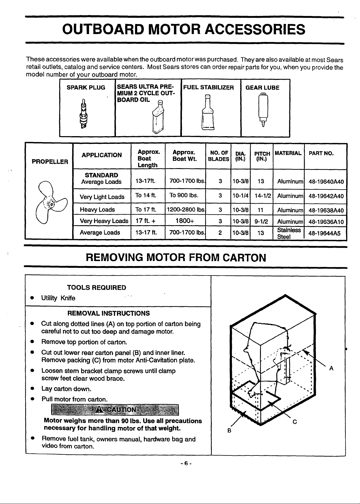
OUTBOARD MOTOR ACCESSORIES
These accessories were available when the outboard motor was purchased. They are also available at most Sears
retail outlets, catalog and service centers. Most Sears stores can order repair parts for you, when you provide the
model number of your outboard motor.
PROPELLER
SPARK PLUG
APPLICATION
STANDARD
Average Loads
Very Light Loads
Heavy Loads
Very Heavy Loads
Average Loads
SEARS ULTRA PRE-
MIUM 2 CYCLE OUT-
BOARD OIL
Approx.
Boat
Len_lth
13-17ft.
To 14 ft.
To 17 ft.
17 ft. +
13-17 ft.
I I
1200-2800 Ibs
iFUEL STABILIZER
Approx.
Boat Wt.
700-1700 Ibs
To 900 Ibs.
1800+
700-1700 Ibs,
GEAR LUBE
0
NO. OF DIA. PITCH
BLADES (IN.) (IN.)
3 10-3/8 13
3 10-114 14-1/2
3 10-3/8 11
3 10-3/8 9-112
2 10-3/8 13
MATERIAL
Aluminum
Aluminum
Aluminum
Aluminum
Stainless
Steel
PART NO.
48-19640A40
48-19642A40
48-19638A40
48-19636A10
48-19644A5
REMOVING MOTOR FROM CARTON
TOOLS REQUIRED
• Utility Knife
REMOVAL INSTRUCTIONS
• Cut along dotted lines (A) on top portion of carton being
careful not to cut too deep and damage motor.
• Remove top portion of carton.
• Cut out lower rear carton panel (B) and inner liner.
Remove packing (C) from motor Anti-Cavitation plate.
• Loosen stem bracket clamp screws until clamp
screw feet clear wood brace.
• Lay carton down.
• Pull motor from carton.
Motor weighs more than 90 Ibs. Use all precautions
necessary for handling motor of that weight.
Remove fuel tank, owners manual, hardware bag and
video from carton.
A
C
B
-6-
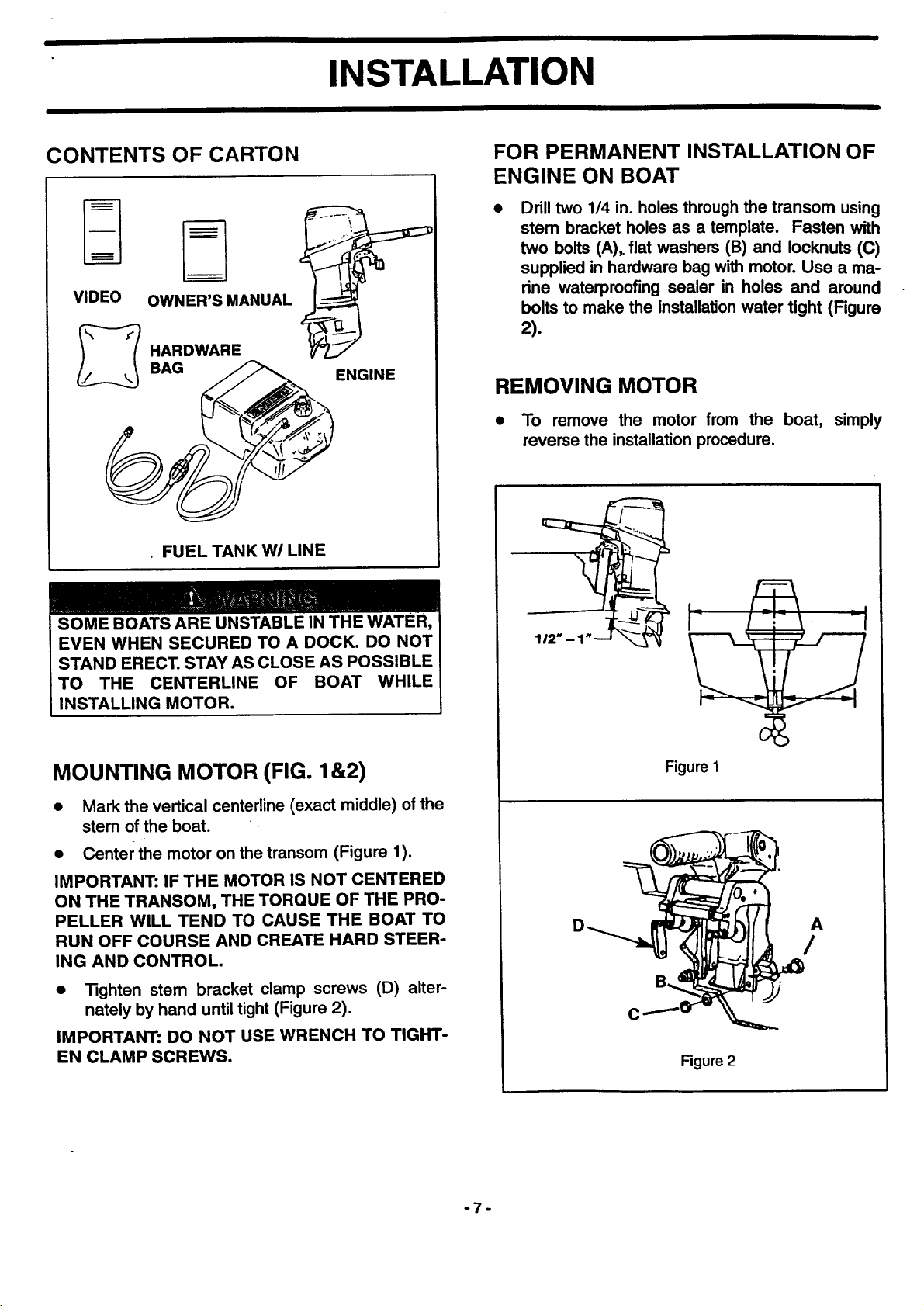
INSTALLATION
CONTENTS OF CARTON
_'_ HARDWARE
J!_._ BAG _ ENGINE
• FUEL TANK W/LINE
FOR PERMANENT INSTALLATION OF
ENGINE ON BOAT
Drill two 1/4 in. holes through the transom using
stem bracket holes as a template. Fasten with
two bolts (A),. flat washers (B) and Iocknuts ((3)
supplied in hardware bag with motor. Use a ma-
rine waterproofing sealer in holes and around
bolts to make the installation water tight (Figure
2).
REMOVING MOTOR
• To remove the motor from the boat,
reverse the installation procedure.
simply
SOME BOATS ARE UNSTABLE IN THE WATER,
EVEN WHEN SECURED TO A DOCK. DO NOT
STAND ERECT. STAY AS CLOSE AS POSSIBLE
TO THE CENTERLINE OF BOAT WHILE
INSTALLING MOTOR.
MOUNTING MOTOR (FIG. 1&2)
• Mark the vertical centerline (exact middle) of the
stem of the boat.
• Center the motor on the transom (Figure 1).
IMPORTANT: IF THE MOTOR IS NOT CENTERED
ON THE TRANSOM, THE TORQUE OF THE PRO-
PELLER WILL TEND TO CAUSE THE BOAT TO
RUN OFF COURSE AND CREATE HARD STEER-
ING AND CONTROL.
• "13ghten stem bracket clamp screws (D) alter-
nately by hand until tight (Figure 2).
IMPORTANT: DO NOT USE WRENCH TO TIGHT-
EN CLAMP SCREWS.
Figure 1
D
A
/
Figure 2
I
-7-
II I
OPERATION
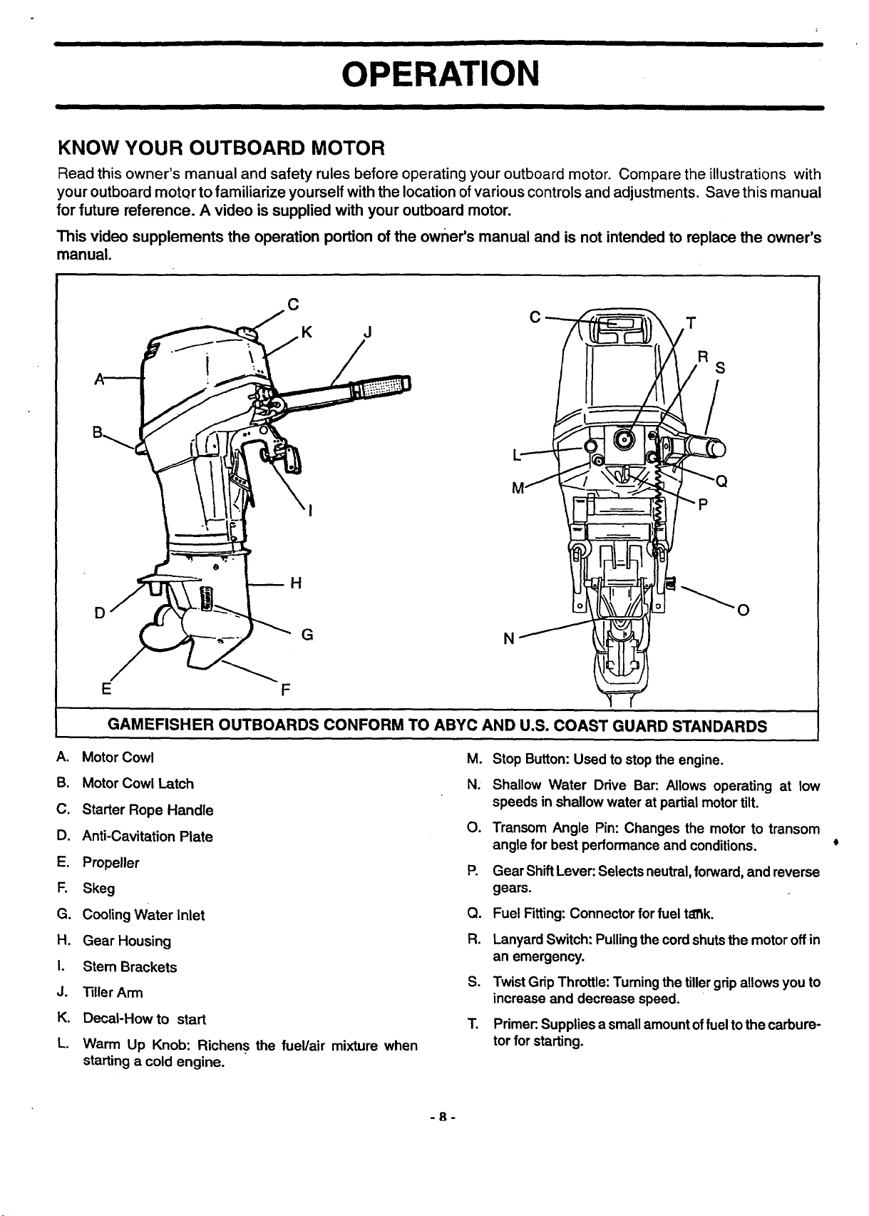
KNOW YOUR OUTBOARD MOTOR
Read this owner's manual and safety rules before operating your outboard motor. Compare the illustrations with
your outboard motQr to familiarize yourself with the location of various controls and adjustments. Save this manual
for future reference. A video is supplied with your outboard motor.
This video supplements the operation portion of the owner's manual and is not intended to replace the owner's
manual.
D
E F
C
K J
H
G N
C
T
S
P
GAMEFISHER OUTBOARDS CONFORM TO ABYC AND U.S. COAST GUARD STANDARDS
A. Motor Cowl
B. Motor Cowl Latch
C. Starter Rope Handle
D. Anti-Cavitation Plate
E. Propeller
F. Skeg
G. Cooling Water Inlet
H. Gear Housing
I. Stem Brackets
J. Tiller Arm
K. Decal-How to start
L. Warm Up Knob: Richens the fuel/air mixture when
starting a cold engine.
M. Stop Button: Used to stop the engine.
N. Shallow Water Drive Bar: Allows operating at low
speeds in shallow water at partial motortilt.
O. Transom Angle Pin: Changes the motor to transom
angle for best performance and conditions.
P. Gear ShiftLever:Selects neutral,forward,and reverse
gears.
Q. Fuel Fitting:Connector for fuel t_fflk.
R. Lanyard Switch: Pullingthe cordshutsthe motoroffin
an emergency.
S. TwistGripThrottle: Turning the tillergripallowsyou to
increase and decrease speed.
3". Primer:.Supplies a small amountoffueltothe carbure-
tor for starting.
-8-
OPERATION
HOW TO USE YOUR OUTBOARD
MOTOR
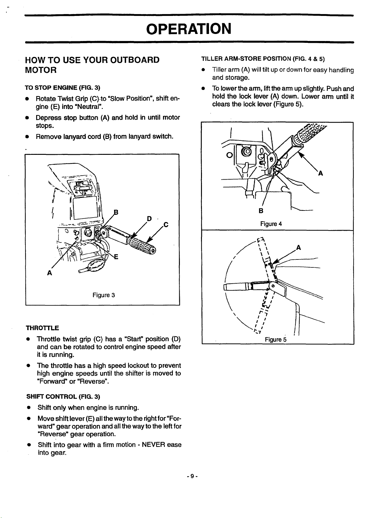
TO STOP ENGINE (FIG. 3)
• Rotate Twist Grip (C).to "Slow Position", shift en-
gine (E) into "Neutral".
• Depress stop button (A) and hold in until motor
stops.
• Remove lanyard cord (B) from lanyard switch.
D
TILLER ARM-STORE POSITION (FIG. 4 & 5)
• Tiller arm (A) will tilt up or down for easy handling
and storage.
• To lower the arm, liftthe arm up slightly. Push and
hold the lock lever (A) down. Lower arm until it
clears the lock lever (Figure 5).
I
O
B
Figure 4
A
Figure 3
THROTTLE
• Throttle twist grip (C) has a "Start" position (D)
and can be rotated to control engine speed after
it is running.
• The throttle has a high speed lockout to prevent
high engine speeds until the shifter is moved to
"Forward" or "Reverse".
SHIFT CONTROL (FIG. 3)
• Shift only when engine is running.
• Move shift lever (E) all the way to the right for"For-
ward" gear operation and all the way to the left for
"Reverse" gear operation.
• Shift into gear with a firm motion - NEVER ease
into gear.
A
-9-
OPERATION
III
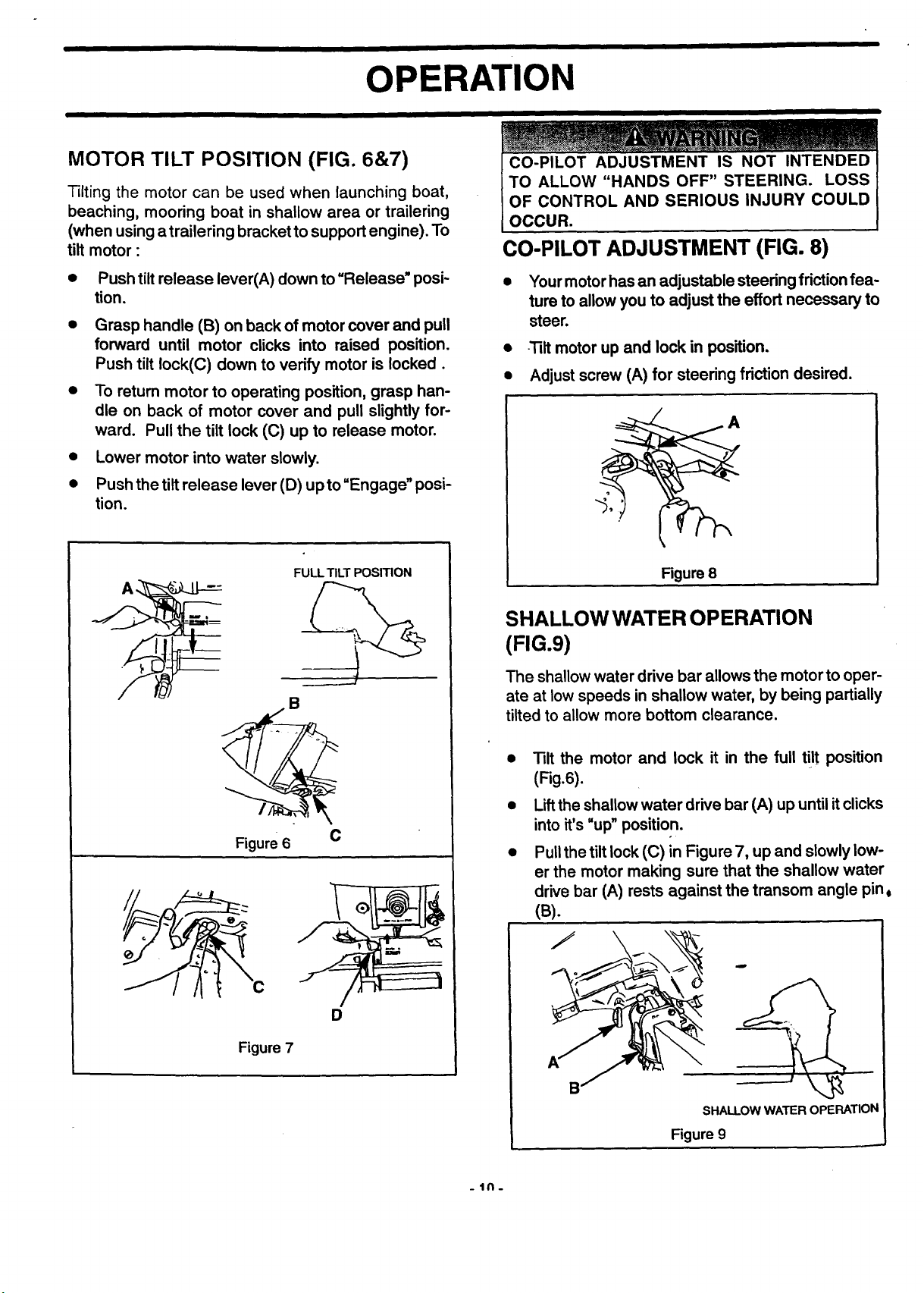
MOTOR TILT POSITION (FIG. 6&7)
Tilting the motor can be used when launching boat,
beaching, mooring boat in shallow area or trailering
(when using a trailering bracket to support engine). To
tilt motor :
Push tilt release lever(A) down to "Release" posi-
tion.
• Grasp handle (B) on back of motor cover and pull
forward until motor clicks into raised position.
Push tilt lock(C) down to verify motor is locked.
• To return motor to operating position, grasp han-
dle on back of motor cover and pull slightly for-
ward. Pull the tilt lock (C) up to release motor.
• Lower motor into water slowly.
• Push the tilt release lever (D) up to"Engage" posi-
tion.
FULL TILT POSITION
CO-PILOT ADJUSTMENT IS NOT INTENDED
TO ALLOW "HANDS OFF" STEERING. LOSS
OF CONTROL AND SERIOUS INJURY COULD
OCCUR.
CO-PILOT ADJUSTMENT (FIG. 8)
• Yourmotorhasan adjustable steeringfriction fea-
ture to allowyou to adjust the effortnecessary to
steer.
• -'_it motor up and lock in position.
• Adjust screw (A) for steering friction desired.
Figure 8
Figure 6 C
Figure 7
SHALLOW WATER OPERATION
(FIG.9)
The shallow water drive bar allows the motor to oper-
ate at low speeds in shallow water, by being partially
tilted to allow more bottom clearance.
Tilt the motor and lock it in the full ti!t position
(Fig.6).
Lift the shallow water drive bar (A) up until it clicks
into it's "up" position.
Pull the tilt lock (C) in Figure 7, up and slowly low-
er the motor making sure that the shallow water
drive bar (A) rests against the transom angle pin 0
(B).
7
D
_IN.
SHALLOW WATER OPERATION
Figure 9
OPERATION
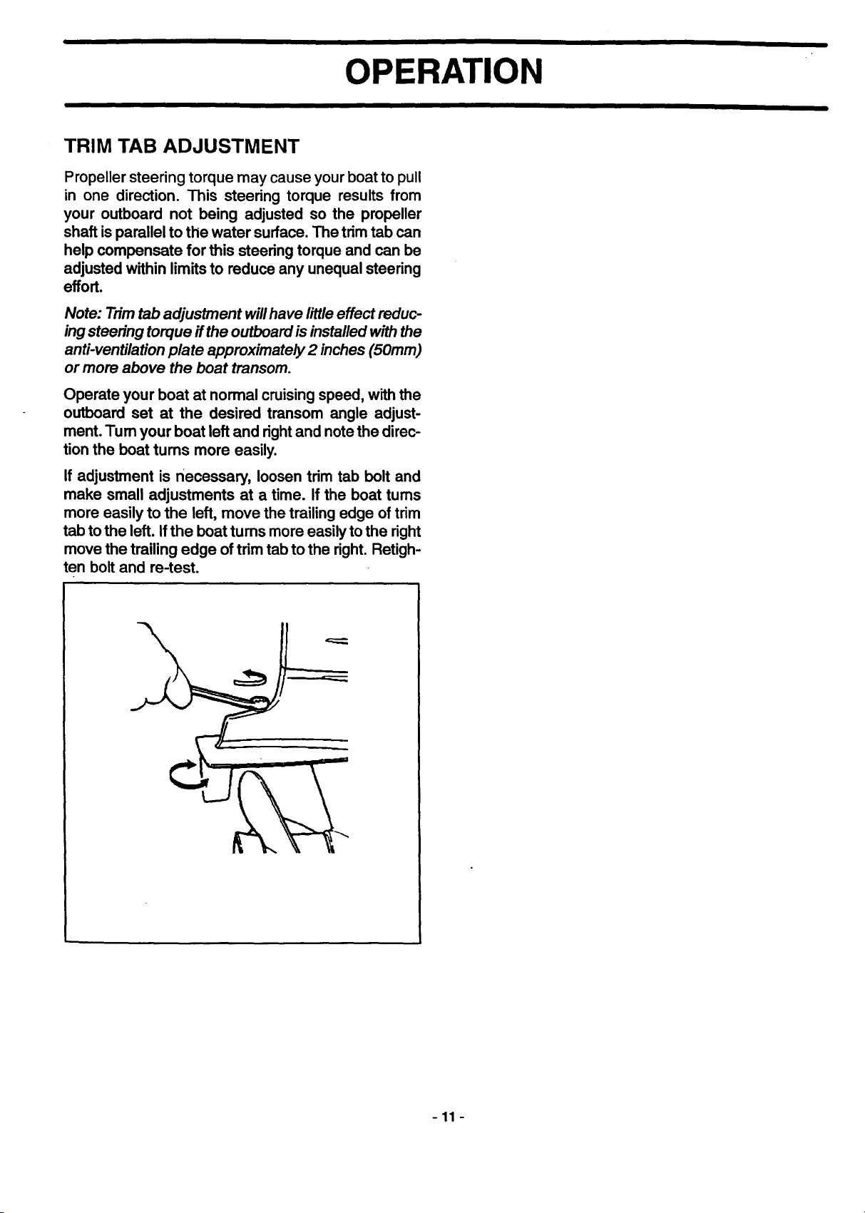
TRIM TAB ADJUSTMENT
Propeller steering torque may cause your boat to pull
in one direction. This steering torque results from
your outboard not being adjusted so the propeller
shaft isparallel to the water surface.The trimtab can
help compensate for this steering torque and can be
adjusted withinlimits to reduce any unequalsteering
effort.
Note: Trim tab adjustment will have little effect reduc-
ing steering torque if the outboard is installed with the
anti-ventilation plate approximately 2 inches (50mm)
or more above the boat transom.
Operate your boat at normal cruisingspeed, with the
outboard set at the desired transom angle adjust-
ment. Tum your boat left and rightand note the direc-
tion the boat tums more easily.
If adjustment is necessary, loosen trim tab bolt and
make small adjustments at a time. If the boat turns
more easily to the left, move the trailing edge oftrim
tab to the left. If the boat turns more easily to the right
movethe trailing edge of trimtab to the right. Retigh-
ten boltand re-test.
-11 -
OPERATION
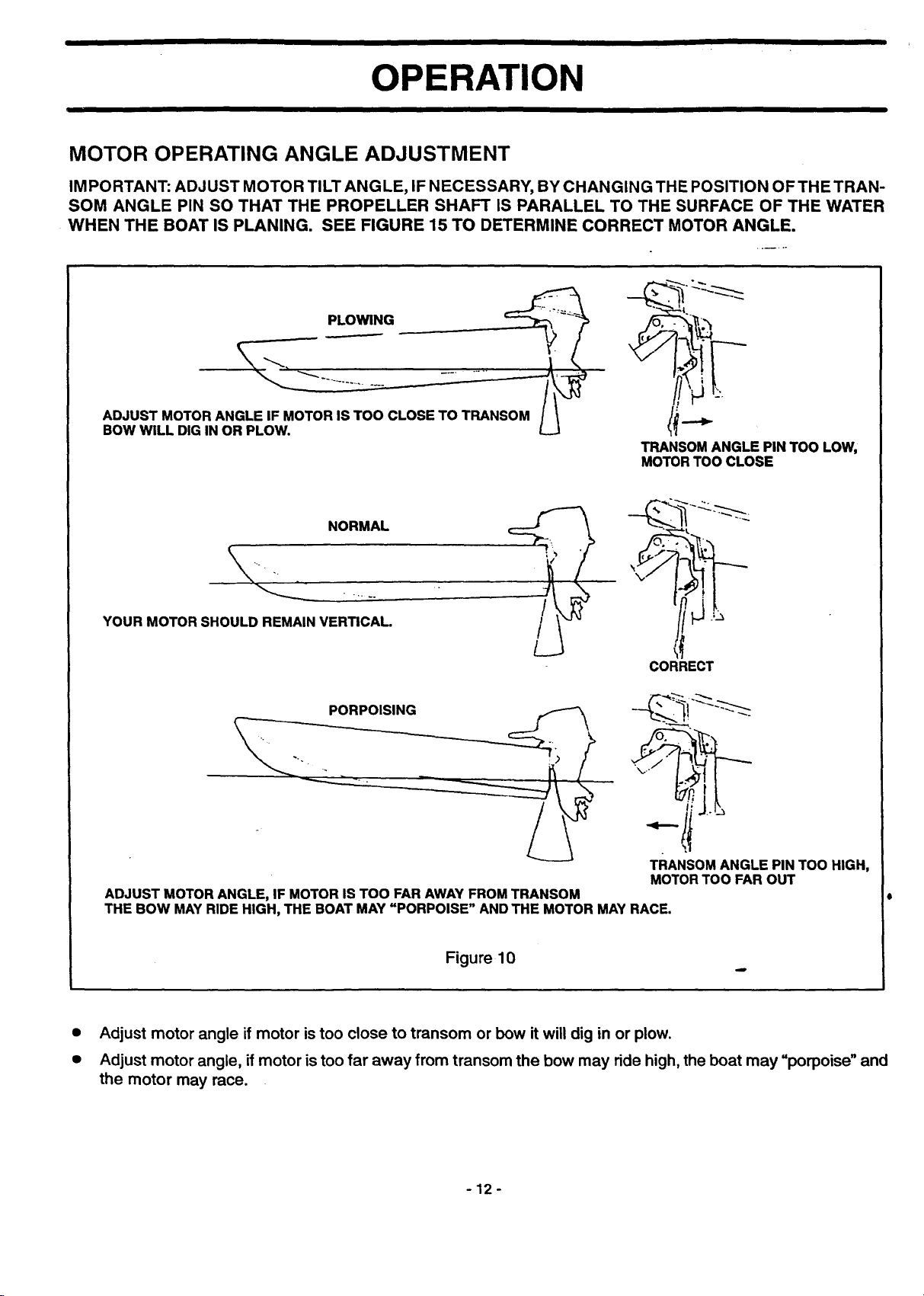
MOTOR OPERATING ANGLE ADJUSTMENT
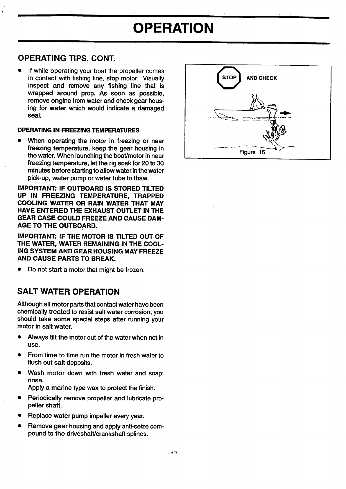
IMPORTANT: ADJUST MOTOR TILT ANGLE, IF NECESSARY, BY CHANGING THE POSITION OF THE TRAN-
SOM ANGLE PIN SO THAT THE PROPELLER SHAFT IS PARALLEL TO THE SURFACE OF THE WATER
WHEN THE BOAT IS PLANING. SEE FIGURE 15 TO DETERMINE CORRECT MOTOR ANGLE.
PLOWING
ADJUST MOTOR ANGLE IF MOTOR IS TOO CLOSE TO TRANSOM I \
BOW WILL DIG IN OR PLOW. L_J
TRANSOM ANGLE PIN TOO LOW,
MOTOR TOO CLOSE
NORMAL
YOUR MOTOR SHOULD REMAIN VERTICAL
/
L
CORRECT
TRANSOM ANGLE PIN TOO HIGH,
MOTOR TOO FAR OUT
ADJUST MOTOR ANGLE, IF MOTOR IS TOO FAR AWAY FROM TRANSOM
THE BOW MAY RIDE HIGH, THE BOAT MAY uPORPOISE" AND THE MOTOR MAY RACE.
Figure 10
• Adjust motor angle if motor is too close to transom or bow it will dig in or plow.
• Adjust motor angle, if motor is too far away from transom the bow may ride high, the boat may "porpoise" and
the motor may race.
-12-
OPERATION
PRE-OPERATING CHECK LIST
_1 Boat is rated for motor horsepower and load
conditions.
I_1 Operator knows safe navigation, boating and
operating procedures.
I_1 All needed safety equipment is on board, in good
condition and easy to reach.
I_1 Motor is operating normally. If the motor is hard to
start or is not running well, have repairs made
before leaving dockside.
I_ Fuel supply is O.K.
!_1 Use only recommended gasoline and oil and use
only the correct mixture.
I_1 There are no fuel leaks.
I_l Propeller is not fouled or damaged.
I_1 A spare propeller is on board.
I_1 The correct anchor and lines are on board.
I_1 All anchor and mooring lines are neatly coiled out
of the way.
[_l Recreational equipment and fishing gear is
stowed securely.
[_ Bilge is pumped and there are no water leaks.
1_1 Passengers are safely on board.
[_1 The area is clear for operation. Operator is aware
of other boats,skiers,divers,swimmers,etc.
[_ Boat is loaded evenly from front to rear.
[_1 Operator has read and understood the entire
owner's manual
Check tightness of stem bracket clamp screws.
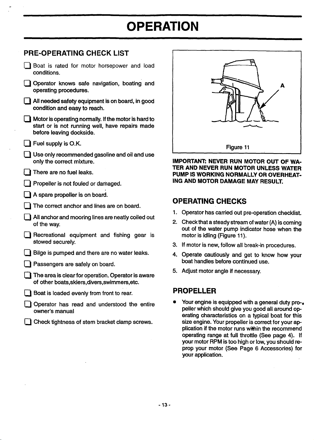
A
Figure 11
IMPORTANT: NEVER RUN MOTOR OUT OF WA-
TER AND NEVER RUN MOTOR UNLESS WATER
PUMP IS WORKING NORMALLY OR OVERHEAT-
ING AND MOTOR DAMAGE MAY RESULT.
OPERATING CHECKS
1. Operator has carried out pre-operation checklist.
2. Checkthat a steadystream of water (A) is coming
out of the water pump indicator hose when the
motor is idling (Figure 11).
3. Ifmotoris new,follow all break-in procedures.
4, Operate cautiously and get to know how your
boat handles before continued use.
5. Adjustmotor angle if necessary.
PROPELLER
Your engine is equipped with a general duty pro-,
peller which should give you good all around op-
erating characteristics on a typical boat for this
size engine. Your propeller is correct for your ap-
plication if the motor runs within the recommend
operating range at full throttle (See page 4). If
your motor RPM is too high or low, you should re-
prop your motor (See Page 6 Accessories) for
your application.
-13-
OPERATION
BEFORE STARTING ENGINE
GASOLINE SELECTION
UNITED STATES AND CANADA
This outboard is designed to operate on any major
brand of automotive unleaded gasoline with a mini-
mum posted octane rating of 87. Mid-grade automo-
tive gasolines that contain fuel injector cleaner are
preferred for added intemal engine cleanliness.
Leaded gasoline is not recommended.
INTERNATIONAL
Use a major brand of automotive unleaded gasoline
with a minimum poster RON of 90. Mid-grade auto-
motive gasoline that contain fuel injector cleaner are
preferred for added intemal engine cleanliness.
Leaded gasoline is acceptable in areas where un-
leaded gasoline is not available. However, exhaust
passageway corrosion may occur due to the accu-
mulation of exhausted lead particles.
IMPORTANT: TO AVOID ENGINE PROBLEMS,
THE FUEL SYSTEM SHOULD BE EMPTIED BE-
FORE STORAGE FOR 30 DAYS OR LONGER.
DRAIN THE FUEL TANK, THEN RUN THE ENGINE
AND LET IT RUN UNTIL IT STOPS. USE FRESH
FUEL NEXT SEASON. SEE STORAGE INSTRUC-
TIONS FOR ADDITIONAL INFORMATION. NEVER
USE ENGINE OR CARBURETOR CLEANER
PRODUCTS IN THE FUEL TANK OR PERMANENT
DAMAGE MAY OCCUR. EXPERIENCE INDI-
CATES THAT ALCOHOL BLENDED FUELS
CALLED GASOHOL (OR USING ETHANOL OR
METHANOL) CAN ATTRACT MOISTURE, WHICH
LEADS TO OIL/GAS SEPARATION AND FORMA-
TION OF ACIDS DURING STORAGE. ACIDIC GAS
CAN DAMAGE THE FUEL SYSTEM OF AN EN-
GINE WHILE IN STORAGE.
If gasoline containing alcohol is used or if you suspect
the presence of alcohol in your gasoline, increase
your inspection of the fuel system, visually checking
for leaks or abnormalities.
stabilizer container. Run engine at least 5 minutes af-
ter adding stabilizer to allow the stabilizer to reach the
carburetor. You do not have to drain the fuel tank for
storage if you are using fuel stabilizer.
OIL RECOMMENDATION
Use SEARS ULTRA PREMIUM Certified TC-W3
2- Cycle Outboard Oil.
Sears Ultra Premium Certified TC-W3 Outboard
Oil is a high grade oilthat provides increased lu-
bricationand extra resistance to carbon buildup
when used with good or varying grades of gaso-
line.
Periodically consult with your Sears store to get the
latest gasoline and oil recommendations. If Sears
2-Cycle Outboard Oil is not available, substitute a 2
Cycle outboard manufacturer's oil or another brand of
2-Cycle outboard oil that is NMMA Certified TC-W3
or TC-WII. The use of an inferior 2-Cycle oil can re-
duce engine durability. Damage from use of an inferi-
or oil may not be covered under the limited warranty.
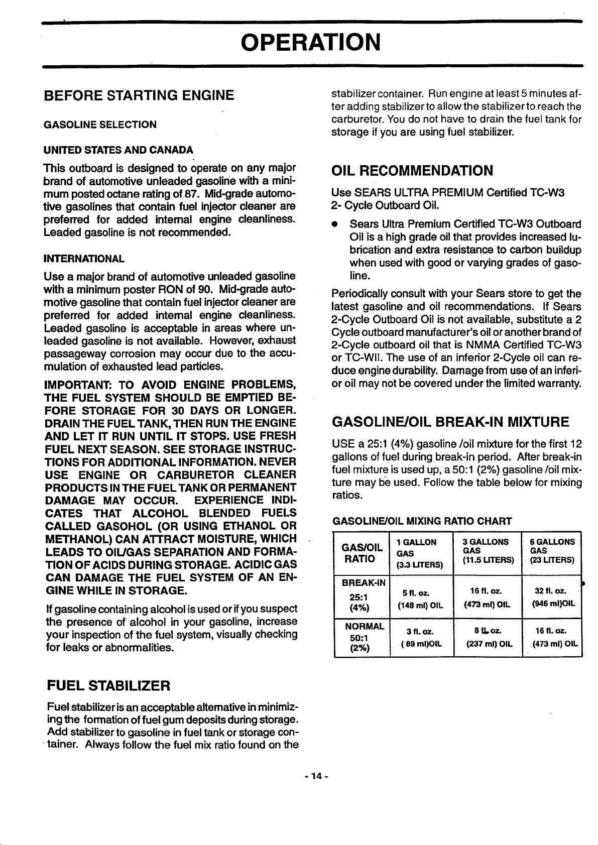
GASOLINE/OIL BREAK-IN MIXTURE
USE a 25:1 (4%) gasoline/oil mixture for the first 12
gallons of fuel during break-in period. After break-in
fuel mixture is used up, a 50:1 (2%) gasoline/oil mix-
ture may be used. Follow the table below for mixing
ratios.
GASOLINE/OIL MIXING RATIO CHART
GAS/OIL
RATIO
BREAK-IN
25:1
(4%)
NORMAL
50:1
(2%)
1 GALLON
GAS
(3.3 UTERS)
5 fl. oz.
(148 ml) OIL
3 fl. oz.
( 89 ml)OIL
3 GALLONS
GAS
(11.5 LITERS)
16fl. oz.
(473 ml) OIL
8 tLoz.
(237 ml) OIL
6 GALLONS
GAS
(23 LITERS)
32 fl. oz.
(946 ml)OIL
16fl. oz.
(473 ml) OIL
FUEL STABILIZER
Fuel stabilizer isan acceptable alternative in minimiz-
ing the formation of fuel gum deposits during storage.
Add stabilizer to gasoline in fuel tank or storage con-
tainer. Always follow the fuel mix ratio found on the
-14-
OPERATION
FILLING FUEL TANK
;!_
gm
AVOID SERIOUS INJURY OR DEATH FROM A
GASOLINE FIRE OR EXPLOSION. ALWAYS
STOP THE ENGINE. DO NOT SMOKE OR
ALLOW OPEN FLAMES OR SPARKS IN THE
AREA WHILE FILLING FUEL TANKS.
• Fill fuel tanks outdoors away from heat, sparks,
and open flames.
• Remove portable fuel tanks from boat to refill
them.
Always stop engine before refilling tanks.
Do not overfill the fuel tank. Fuel will expand in
volume as it's temperature rises and can leak un-
der pressure.
FILLING PORTABLE FUEL TANK
Pour the full amount of oil along with approximately
one gallon of gasoline into the fuel tank. Mix thor-
oughly, then pour the remainder of gasoline into the
tank.
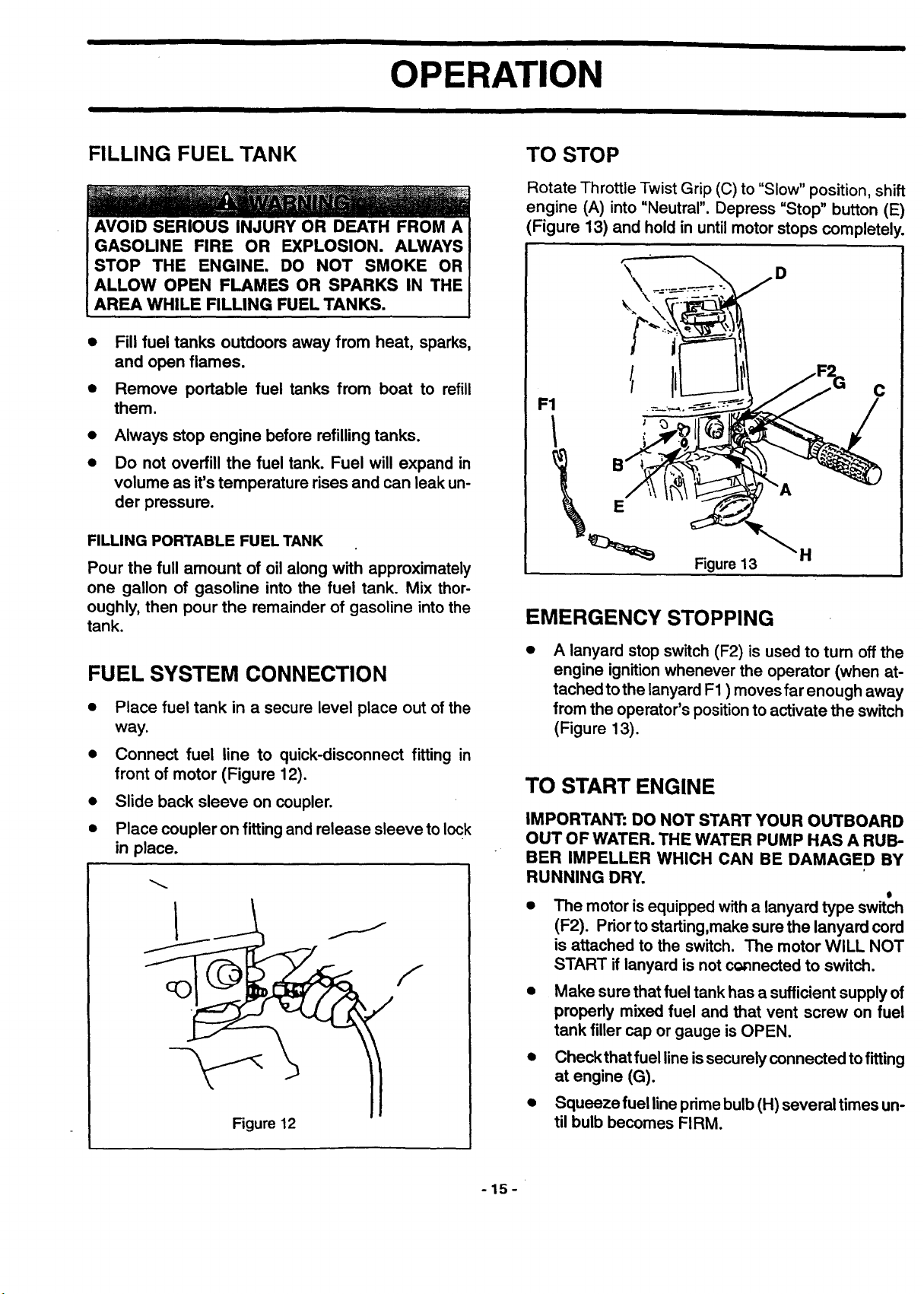
TO STOP
Rotate Throttle Twist Grip (C) to "Slow" position, shift
engine (A) into "Neutral". Depress "Stop" button (E)
(Figure 13) and hold in until motor stops completely.
D
C
F1
E
H
Figure 13
EMERGENCY STOPPING
FUEL SYSTEM CONNECTION
• Place fuel tank in a secure level place out of the
way.
• Connect fuel line to quick-disconnect fitting in
front of motor (Figure 12).
• Slide back sleeve on coupler.
• Place coupler on fitting and release sleeve to lock
in place.
F
A lanyard stop switch (F2) is used to tum off the
engine ignition whenever the operator (when at-
tached tothe lanyard F1 ) moves far enough away
from the operator's position to activate the switch
(Figure 13).
TO START ENGINE
IMPORTANT: DO NOT START YOUR OUTBOARD
OUT OF WATER. THE WATER PUMP HAS A RUB-
BER IMPELLER WHICH CAN BE DAMAGED BY
RUNNING DRY.
0
• The motor is equipped with a lanyard type switch
(F2). Prior to starting,make sure the lanyard cord
is attached to the switch. The motor WILL NOT
START if lanyard is not connected to switch.
• Make sure that fuel tankhas a sufficientsupplyof
properly mixed fuel and that vent screw on fuel
tank filler cap or gauge is OPEN.
• Checkthatfuel line issecurelyconnected tofitting
at engine (G).
Figure 12
• Squeeze fuel line prime bulb (H) several times un-
til bulb becomes FIRM.
-15-
OPERATION
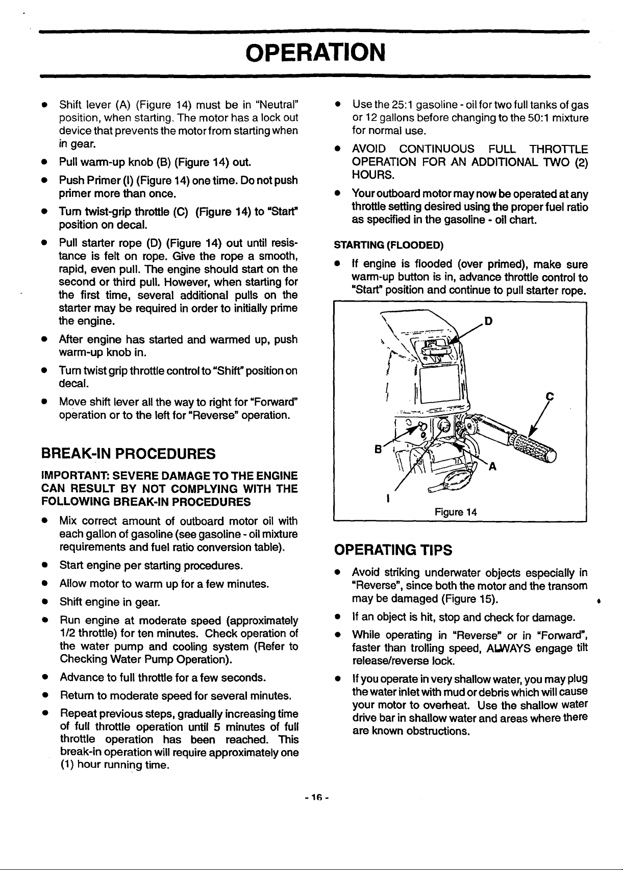
• Shift lever (A) (Figure 14) must be in "Neutral"
position, when starting. The motor has a lock out
device that prevents the motor from starting when
in gear.
• Pull warm-up knob (B) (Figure 14) out.
• Push Primer (I) (Figure 14) one time. Do not push
primer more than once.
• Turn twist-grip throttle (C) (Figure 14) to "Start"
position on decal.
• Pull starter rope (D) (Figure 14) out until resis-
tance is felt on rope. Give the rope a smooth,
rapid, even pull. The engine should start on the
second or third pull. However, when starting for
the first time, several additional pulls on the
starter may be required in order to initially prime
the engine.
• After engine has started and warmed up, push
warm-up knob in.
• Tum twist grip throttle control to"Shift" position on
decal.
Use the 25:1 gasoline - oil for two full tanks of gas
or 12 gallons before changing to the 50:1 mixture
for normal use.
AVOID CONTINUOUS FULL THRO'I-I'LE
OPERATION FOR AN ADDITIONAL TWO (2)
HOURS.
Youroutboardmotormay nowbe operated at any
throttlesetting desired usingthe properfuel ratio
as specifiedinthe gasoline - oil chart.
STARTING (FLOODED)
• If engine is flooded (over primed), make sure
warm-up button is in, advance throttle controlto
"Start" position and continue to pull starter rope.
D
Move shift lever allthe way to rightfor "Forward"
operation or to the left for "Reverse" operation.
BREAK-IN PROCEDURES
IMPORTANT: SEVERE DAMAGE TO THE ENGINE
CAN RESULT BY NOT COMPLYING WITH THE
FOLLOWING BREAK-IN PROCEDURES
• Mix correct amount of outboard motor oil with
each gallon of gasoline (see gasoline - oil mixture
requirements and fuel ratio conversion table).
• Start engine per starting procedures.
• Allow motor to warm up for a few minutes.
• Shift engine in gear.
• Run engine at moderate speed (approximately
112 throttle) for ten minutes. Check operation of
the water pump and cooling system (Refer to
Checking Water Pump Operation).
Advance to full throttle for a few seconds.
Return to moderate speed for several minutes.
Repeat previous steps, gradually increasing time
of full throttle operation until 5 minutes of full
throttle operation has been reached. This
break-in operation will require approximately one
(1) hour running time.
I
Figure 14
OPERATING TIPS
Avoid striking underwater objects especially in
"Reverse", since both the motor and the transom
may be damaged (Figure 15).
If an object is hit, stop and check for damage.
While operating in "Reverse" or in "Forward",
faster than trolling speed, AI,,WAYS engage tilt
release/reverse lock.
If you operate in very shallow water, you may plug
the water inlet with mud or debris which will cause
your motor to overheat. Use the shallow water
drive bar in shallow water and areas where there
are known obstructions.
-16-
OPERATION
OPERATING TIPS, CONT.
If while operating your boat the propeller comes
in contact with fishing line, stop motor. Visually
inspect and remove any fishing line that is
wrapped around prop. As soon as possible,
remove engine from water and check gear hous-
ing for water which would indicate a damaged
seal.
OPERATING IN FREEZING TEMPERATURES
• When operating the motor in freezing or near
freezing temperature, keep the gear housing in
the water. When launchingthe boat/motor innear
freezing temperature, letthe rigsoak for 20 to 30
minutes before startingto allowwater inthe water
pick-up, water pump orwater tube to thaw.
IMPORTANT: IF OUTBOARD IS STORED TILTED
UP IN FREEZING TEMPERATURE, TRAPPED
COOLING WATER OR RAIN WATER THAT MAY
HAVE ENTERED THE EXHAUST OUTLET IN THE
GEAR CASE COULD FREEZE AND CAUSE DAM-
AGE TO THE OUTBOARD.
AND CHECK
Figure 15
IMPORTANT: IF THE MOTOR IS TILTED OUT OF
THE WATER, WATER REMAINING IN THE COOL-
ING SYSTEM AND GEAR HOUSING MAY FREEZE
AND CAUSE PARTS TO BREAK.
• Do not start a motor that might be frozen.
SALT WATER OPERATION
Although all motor parts that contact water have been
chemically treated to resist salt water corrosion, you
should take some special steps after running your
motor in salt water.
• Always tilt the motor out of the water when not in
use.
• From time to time run the motor in fresh water to
flush out salt deposits.
• Wash motor down with fresh water and soap:
rinse.
Apply a marine type wax to protect the finish.
• Periodically remove propeller and lubricate pro-
peller shaft.
• Replace water pump impeller every year.
• Remove gear housing and apply anti-seize com-
pound to the driveshaft/crankshaft splines.
_4"/
CUSTOMER RESPONSIBILITIES
' / /
,,,,,n°°,o°°,
complete regular service // _
Check/Replace fuel line filter •
Clean/Replace fuel tank filter •
Check/Replace spark plug •
Check cooling system •
Check propeller condition •
Check Corrosion Control Anode • •
LUBRICATION FREQUENCY CHART
Shift Linkage
Carb Linkage • •
Swivel Bracket • •
Clamp Screws
Propeller Shaft • •
SERVICE DATES
Gear Check level •
Housing Replace lubricant •
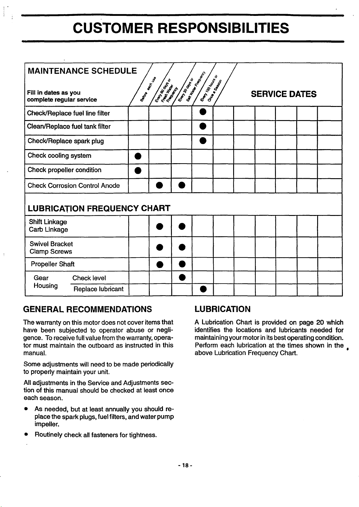
GENERAL RECOMMENDATIONS
The warranty on this motor does not cover items that
have been subjected to operator abuse or negli-
gence. To receive full value from the warranty, opera-
tor must maintain the outboard as instructed in this
manual.
Some adjustments will need to be made periodically
to properly maintain your unit.
All adjustments in the Service and Adjustments sec-
tion of this manual should be checked at least once
each season.
As needed, but at least annually you should re-
place the spark plugs, fuel filters, and water pump
impeller.
Routinely check all fasteners for tightness.
LUBRICATION
A Lubrication Chart is provided on page 20 which
identifies the locations and lubricants needed for
maintaining your motor in its best operating condition.
Perform each lubrication at the times shown in the
above Lubrication Frequency Chart.
-18-