

Craftsman 225581498 Owner’s Manual
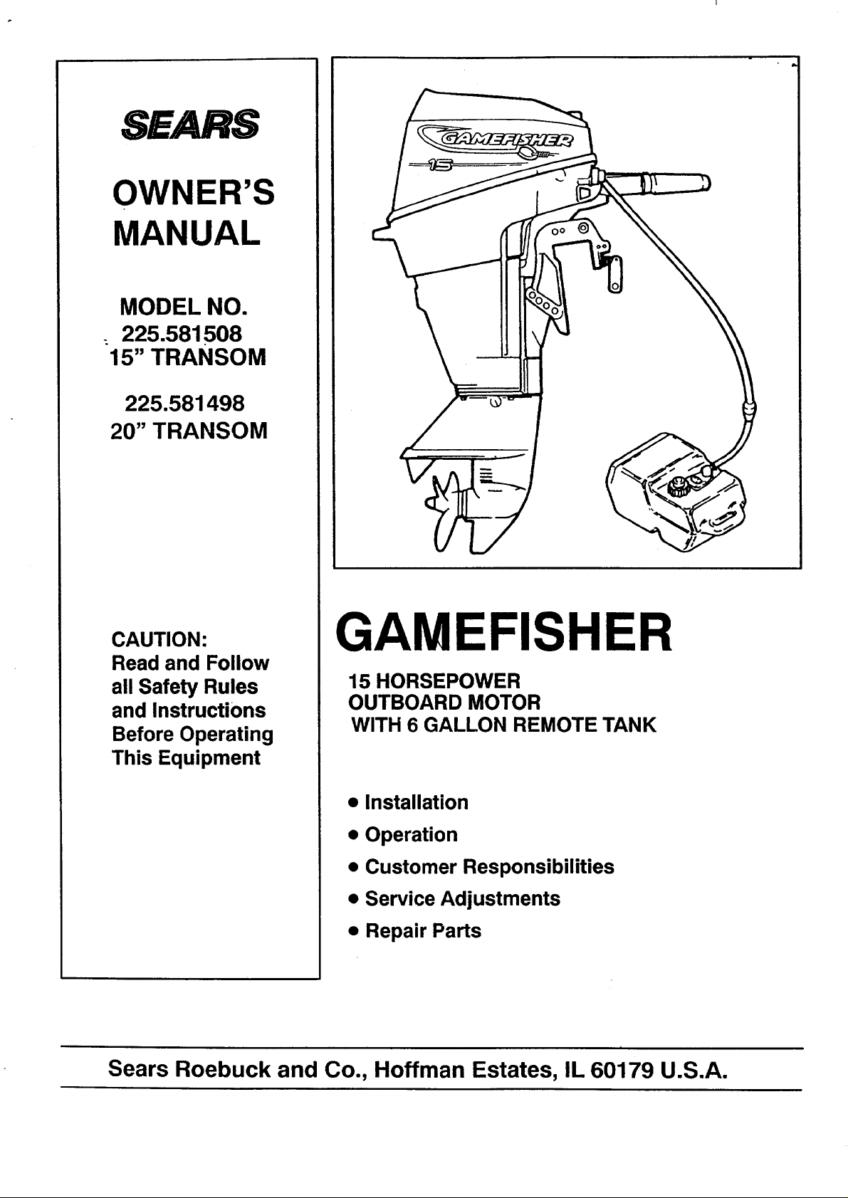
SEARS
OWNER'S
MANUAL
MODEL NO.
225.581508
15" TRANSOM
225.581498
20" TRANSOM
CAUTION:
Read and Follow
all Safety Rules
and Instructions
Before Operating
This Equipment
GAMEFISHER
15 HORSEPOWER
OUTBOARD MOTOR
WITH 6 GALLON REMOTE TANK
• Installation
• Operation
• Customer Responsibilities
• Service Adjustments
• Repair Parts
Sears Roebuck and Co., Hoffman Estates, IL 60179 U.S.A.
BOATER'S RESPONSIBILITIES
ii i iii i I
SAFETY RULES
The operator (driver) is responsible for the correct and
safe operation of the boat and safety of its occupants
and general public. It is strongly recommended that
each operator (driver) read and understand this entire
manual before operating the outboard.
Be sure at least one additional person on board is
instructed in the basics of starting and operating the
outboard and boat handling in case the driver is unable
to operate the boat.
BEFORE OPERATING YOUR OUTBOARD
Read this manual carefully. Learn how to operate your
outboard properly. If you have any questions, contact
your nearest Sears Store which sells Gamefisher out-
board motors.
Safety and operating information that is practiced along
with using good common sense can help prevent per-
sonal injury and product damage.
This manual as well as safety labels posted on the out-
board use the following safety alerts to draw your atten-
tion to special safety instructions that should be fol-
lowed.
USING AN OUTBOARD THAT EXCEEDS THE MAXI-
MUM HORSEPOWER LIMIT OF A BOAT CAN:
1. CAUSE LOSS OF BOAT CONTROL, 2. PLACE TOO
MUCH WE|GHT AT THE TRANSOM ALTERING THE
DESIGNED FLOTATION CHARACTERISTICS OF
THE BOAT OR 3. CAUSE THE BOAT TO BREAK
APART PARTICULARLY AROUND THE TRANSOM
AREA. OVERPOWERING A BOAT CAN RESULT IN
SERIOUS INJURY, DEATH OR BOAT DAMAGE.
DO NOT attempt to make repairs or adjustments not
specifically covered in this manual. Should you ever
need technical assistance, please contact your Sears
Service Center.
NEVER OPERATE your motor at full throttle when the
engine isoverloaded. This can occur under conditions
when a planing boat is loaded so it does not plane or
when towing another boat.
• Some boats are extremely unstable in the water, even
when secured to a dock. Do not stand erect. Stay as
close as possible to centerline of boat while installing
motor.
• DO NOT store your motor or gasoline where fumes
may reach an open flame and cause a fire.
IMMEDIATE HAZARDS WHICH WILL RESULT IN
SEVERE PERSONAL INJURY OR DEATH.
HAZARDS OR UNSAFE PRACTICES WHICH COULD
RESULT IN SEVERE PERSONAL INJURY OR DEATH.
I _ .CAUTION I
HAZARDS OR UNSAFE PRACTICES WHICH COULD
RESULT IN MINOR INJURY OR PRODUCT OR PRO-
PERTY DAMAGE.
ALWAYS DISCONNECT SPARK PLUG WIRES AND
PLACE WIRES WHERE THEY CANNOT CONTACT
SPARK PLUGS TO PREVENT ACCIDENTAL START-
ING WHEN WORKI_IG ON YOUR OUTBOARD
MOTOR.
• DO NOT use a motor with a horsepower rating higher
than what is listed (_nthe certification plate on your
boat.
DRAIN THE GASOLINE from your motor before
transporting your motor inside your car or other
vehicle.
GASOLINE AND ITS VAPORS ARE EXTREMELY
FLAMMABLE AND HIGHLY EXPLOSIVE UNDER
CERTAIN CONDITIONS. ALWAYS STOP THE EN-
GINE AND DO NOT SMOKE OR ALLOW OPEN
FLAMES OR SPARKS IN THE AREA WHILE FILLING
FUEL TANKS.
• DO NOT fill the gas tank when the engine is running.
Do not fill the gas tank indoors.
• REMOVE portable fuel tank from boat when refueling
to prevent spilling fuel in boat. Always mix fuel in a
well ventilated area.
2
CONGRATULATIONS...
PRODUCT SPECIFICATIONS
You are to be congratulated on your selection of this
Outboard Motor which will give you years of satisfactory
service. Your Gamefisher is the end product of years of
research, engineering and development. It has been
assembled by Craftsmen who take pride in their work.
This Owner's Guide will help you to receive all the
trouble-free performance built into your motor. READ
THROUGH THIS MANUAL CAREFULLY BEFORE
OPERATING THE MOTOR. It contains complete operat-
ing instructions and recommendations for the care and
protection of your motor. Following these recommenda-
tions and instructions will assure you of years of boating
pleasure.
I
Outboarding is a great _port. Always remember, how-
ever, that you have friends on the water. Extend to them
the courtesy of thoughtful, safe operation of your motor
and boat and you will increase your own enjoyment.
MODEL
NUMBER
SERIAL
NUMBER
DATE OF
PURCHASE
THE MODEL AND SERIAL NUMBERS WILL BE
FOUND ON A DECAL ATTACHED TO THE PORT
STERN BRACKET.
YOU SHOULD RECORD BOTH SERIAL NUMBER
AND DATE OF PURCHASE AND KEEP IN A SAFE
PLACE FOR FUTURE REFERENCE.
Engine 15 HP
Horsepower Rating @ 6000 RPM
Recommended
5500 - 6500 RPM
Operating Range
Engine Type Two Cycle, Two Cylinder
Bore and Stroke
Alternate Firing
2.25" x 1.94"
57.1 mm x 49.2 mm)
Cubic Inch 15.41 Cubic Inches
Displacement (252.5 cc)
Water Cooled - Displacement
Cooling Type Water Pump
Propeller Right Hand Rotation,
Spline Drive
Spark Plug - Champion 33-328
Spark Plug Gap 0.040 in. (1.0 mm)
Fuel Tank Remote 6.0 gal. (23 L)
Gear Ratio 14:22
15" Leg = 62 Ibs. (28.1 Kg)
Weight (approx.) 20" Leg = 64 Ibs. (29.0 Kg)
Fuel:Oil Ratio
25:1 Break-In
50:1 Normal
CUSTOMER RESPONSIBILITIES
• Read and observe the safety rules.
• Follow a regular schedule in maintaining, caring for
and using your outboard motor.
• Followthe instructions under"Cus.tomer Responsibil-
ities" and "Storage" sections of this Owner's Manual.
ONE YEAR LIMITED WARRANTY ON GAMEFISHER OUTBOARD MOTOR
Foroneyearfrom the date of purchase, when this Gamefisher Outboard Motor ismaintained, lubricated and tuned-
up according to the instructions inthe owner's manual, Sears will repair,free ofcharge, any defect in material and
workmanship.
Ifthis Gamefisher Outboard Motor is used for commercial orrentalpurposes, thiswarranty applies foronly 90 days
from the date of purchase.
This warranty does notcover:
• Expendable items which become worn during normal use, such as sparkplugs, water pump impeller, oil seals,
propellers and tune-ups.
• Repairs necessary because of operator abuse or negligence, includingbutnot limited to strikingan underwater
object and failure to maintain the equipment according to the instructionscontained in the owner's manual.
WARRANTY SERVICE IS AVAILABLE BY RETURNING THE GAMEFISHER OUTBOARD MOTOR TO THE
NEAREST SEARS SERVICE CENTER/DEPARTMENT IN THE UNITED STATES. THIS WARRANTY APPLIES
ONLY WHILE THIS PRODUCT IS IN USE IN THE UNITED STATES.
This warranty gives you specific legal rights, and you may also have other rightswhich may vary from state to
state.
._ SEARS, ROEBUCK AND CO. Department 817WA, Hoffman Estates, IL 60179
TABLE OF CONTENTS
SAFETY RULES ................................. 2
MOTOR SPECIFICATIONS ...................... 3
WARRANTY ..................................... 3
MOTOR ACCESSORIES ......................... 5
INSTALLATION ................................. 7
MOTOR NOMENCLATURE ...................... 8
OPERATION ................................. 8-16
INDEX
B
Before Starting Engine ....... 12
Index ........................ 4
Boat Transom ................ 7
Break-In Procedure .......... 13
Know Your Outboard Motor . .. 8
C
Carburetor .................. 25
Cooling System ............. 15
Customer Responsibilities .... 17
Lanyard Stop Switch .......... 6
Lubrication Schedule ........ 17
Lubrication Code ............ 22
D
Draining/Refilling Gear
Housing Lubricant ......... 23
Maintenance Schedule ....... 17
Mounting Motor .............. 7
E
Exterior Care ................ 27
Motor Tilt Angle ............. 11
Motor Speed (RPM) and
Propeller ................. 15
F
Motor Tilt .................... 9
Fuel Pump Filter ............. 19
Fuel Ratio Conversion Table .o 12
Fuel System ................ 11
Fuel Tank Filter ............. 19
Oil Selection ................ 12
Operating Checks ........... 15
Operating In Freezing
G
Gasoline Selection .......... 12
General Recommendations... 17
Temperatures ............. 16
Pre-Operation Checklist ..... 16
Product Specifications ........ 3
Propeller ................... 11
Propeller Removal ........... 21
CUSTOMER RESPONSIBILITIES ............. 17-24
SERVICE AND ADJUSTMENTS ................. 25
STORAGE .................................. 26-27
TROUBLESHOOTING POINTS .................. 28
REPAIR PARTS ................................ 29
PARTS ORDERING .................. REAR COVER
I
R
Removing Motor ............. 7
Remove Motor Cover ........ 18
K
S
Salt Water Operation ........ 16
L
Shakedown Checklist ........ 16
Shallow Water Drive Bar ..... 10
Spark Plug .................. 20
Start Engine ................ 14
Steering Friction ............. 9
M
Storage ..................... 26
Submerged Motor
Fresh Water ............... 24
Submerged Motor
Salt Water ................ 24
T
Tiller Handle Position ........ 10
O
Throttle Stop ................ 25
Troubleshooting Chart ....... 28
W
Warranty .................... 3
P
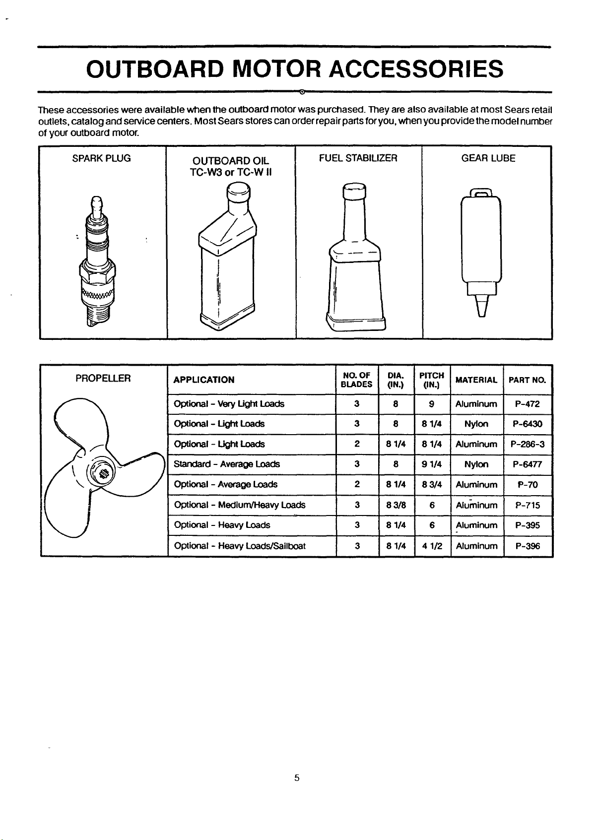
OUTBOARD MOTOR ACCESSORIES
These accessories were available when the outboard motor was purchased. They are also available at most Sears retail
outlets, catalog and service centers. Most Sears stores can order repair parts for you, when you provide the model number
of your outboard motor.
SPARK PLUG
PROPELLER
OUTBOARD OIL
TC-W3 or TC-W !1
i
APPLICATION
opuonal- Veryug_ Loads
Optional- Ught Loads
Optional - Light Loads
FUEL STABILIZER GEAR LUBE
NO. OF DIA.
BLADES (IN.)
3 8
3 8
2 8 1/4
PITCH
(IN.)
9
8 1/4
8 1/4
MATERIAL
Aluminum
Nylon
Aluminum
PARTNO.
P-472
P-6430
P-286-3
Standard - Average Loads
Optional - Average Loads
Optional - Medium/Heavy Loads
Optional - Heavy Loads
Optional - Heavy Loads/Sailboat
3 8
2 8 1/4
3 8 3/8
3 8 1/4
3 8 1/4
9 1/4
8 3/4
6
6
4 1/2
Nylon
Aluminum
Aluminum
Aluminum
Aluminum
P-6477
P-70
P-715
P-395
P-396
5
i ii
GENERAL INFORMATION
LANYARD STOP SWITCH
1 The purpose of the lanyard stop switch is to turn off
the engine ignition whenever the operator (when at-
tached to the lanyard) moves far enough away from the
operator's position to activate the switch.
2 The lanyard is a cord usually between 4 and 5 feet in
length when stretched out with an element on one end
made to be inserted into the switch and a metal snap on
the other end for attaching to the operator. It is coiled to
make its at-rest condition as short as possible so as to
minimize the likelihood of the lanyard entanglement
with nearby objects. It is made as long as it is in its
stretched condition to minimize the likelihood of acci-
dental activation should the operator choose to move
around in an area close to the normal operator's posi-
tion. If for any reason it is desired to have a shorter
functional lanyard, this may be accomplished by using
up length in the way the lanyard and clip are attached to
the operator (such as wrapping the lanyard around the
operator's wrist or leg) or by tying a simple knot in the
lanyard.
Read the Safety Warning following before electing to
use or not to use such a switch.
THE FOLLOWING ADVANTAGES AND DISADVAN-
TAGES OF A LANYARD STOP SWITCH SHOULD BE
CONSIDERED BEFORE ELECTING TO USE, OR NOT
TO USE, SUCH A SWITCH.
ADVANTAGES: THE PURPOSE OF A LANYARD STOP
SWITCH IS TO STOP THE ENGINE IGNITION WHEN-
EVER THE OPERATOR (WHEN ATTACHED TO THE
LANYARD) MOVES FAR ENOUGH AWAY FROM THE
OPERATOR'S POSITION TO ACTIVATE THE
SWITCH. THIS WOULD OCCUR IF THE OPERATOR
FALLS OR MOVES WITHIN THE BOAT A SUFFI-
CIENT DISTANCE FROM THE OPERATOR'S POSI-
TION. THIS TYPE OF ACCIDENT IS MOST LIKELY IN
CERTAIN TYPES OF BOATS SUCH AS LOW-SIDED
BASS BOATS, HIGH-PERFORMANCE BOATS AND
LIGHT, SENSITIVE-HANDLING FISHING BOATS
OPERATED BY HAND-TILLER. IT IS ALSO LIKELY AS
A RESULT OF POOR OPERATING PRACTICES SUCH
AS SITTING ON THE BACK OF THE SEAT AT PLAN-
ING SPEEDS, STANDING AT PLANING SPEEDS,
OPERATING AT HIGH SPEEDS IN SHALLOW OR
OBSTACLE-INFESTED WATERS, RELEASING YOUR
GRIP ON A STEERING WHEEL THAT IS PULLING IN
ONE DIRECTION, DRINKING AND DRIVING OR
DARING, HIGH-SPEED BOAT MANEUVERS.
DISADVANTAGES: INADVERTENT ACTIVATION OF
THE SWITCH IS ALSO A POSSIBILITY. THIS COULD
CAUSE ANY, OR ALL, OF THE FOLLOWING POTEN-
TIALLY HAZARDOUS SITUATIONS:
1, LOSS OF BALANCE AND FALLING FORWARD OF
UNSTABLE BOAT PASSENGERS- A PARTICULAR
CONCERN IN BOW RIDER TYPE BOATS.
2. LOSS OF POWER AND DIRECTIONAL CONTROL
IN HEAVY SEAS, STRONG CURRENT OR HIGH
WINDS.
3. LOSS OF CONTROL WHEN DOCKING.
IN ADDITION, THERE ARE LIMITATIONS TO WHAT
THE LANYARD STOP SWITCH CAN DO. THE BOAT
CAN CONTINUE TO COAST FOR A CONSIDERABLE
DISTANCE DEPENDING ON THE VELOCITY AT
SHUTDOWN AND THE DEGREE OF ANY TURN.
HOWEVER, THE BOAT WILL NOT COMPLETE A
FULL CIRCLE. WHILE THE BOAT IS COASTING, IT
CAN CAUSE INJURY TO ANYONE IN THE BOAT'S
PATH AS SERIOUSLY AS THE BOAT WOULD WHEN
UNDER POWER.
AS WE CANNOT POSSIBLY KNOW OF AND ADVISE
THE BOATING PUBLIC OF ALL CONCEIVABLE
BOAT/MOTOR TYPES AND/OR POOR OPERATING
PRACTICES, THE FINAL DECISION OF WHETHER
TO USE A LANYARD STOP SWITCH RESTS WITH
YOU, THE OWNER/DRIVER.
WE STRONGLY RECOMMEND THAT OTHER OCCU-
PANTS BE INSTRUCTED ON PROPER STARTING
AND OPERATING PROCEDURES SHOULD THEY BE
REQUIRED TO OPERATE THE OUTBOARD AND
BOAT IN AN EMERGENCY.
6
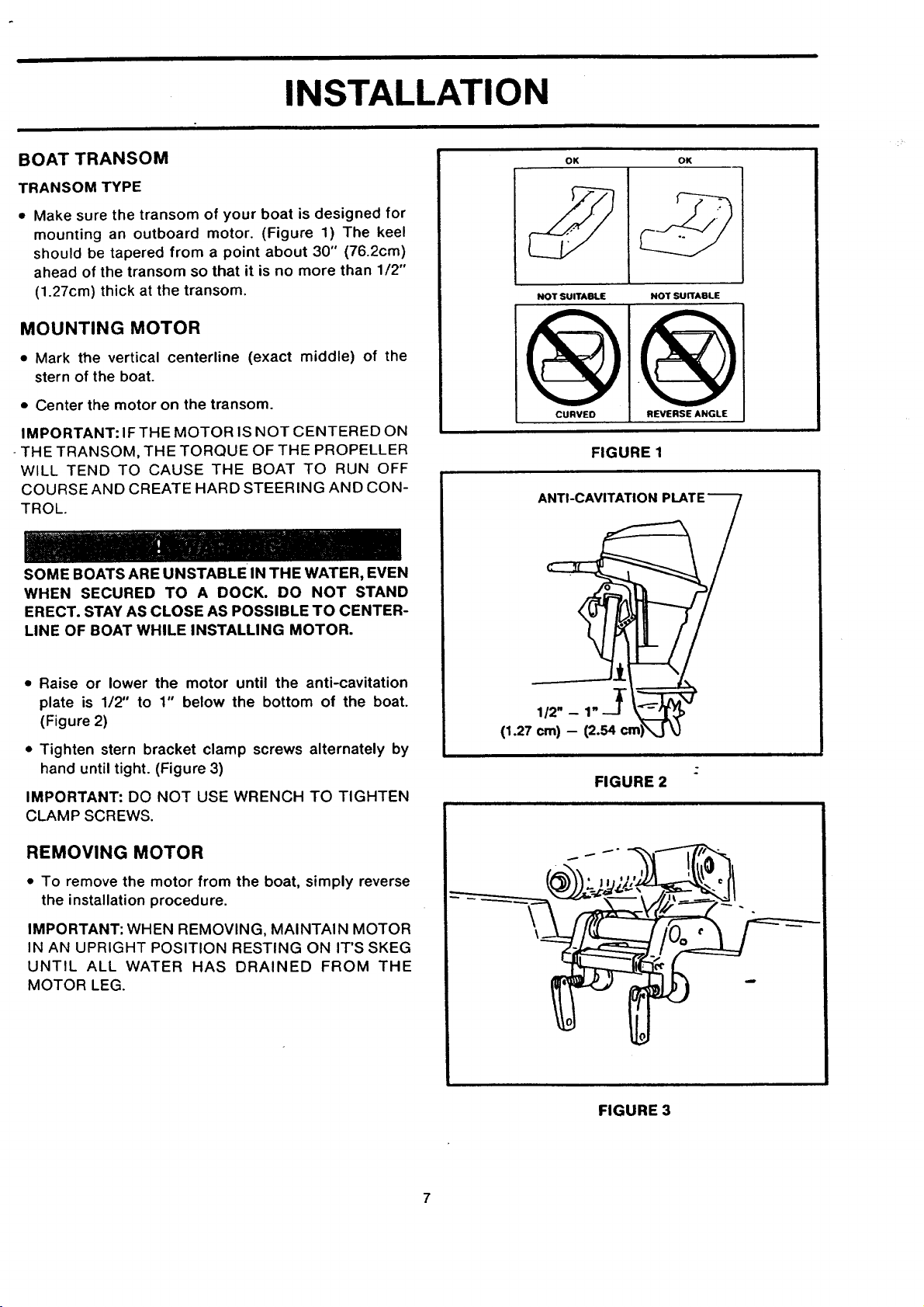
INSTALLATION
BOATTRANSOM
TRANSOM TYPE
• Make sure the transom of your boat is designed for
mounting an outboard motor. (Figure 1) The keel
should be tapered from a point about 30" (76.2cm)
ahead of the transom so that it is no more than 1/2"
(1.27cm) thick at the transom.
MOUNTING MOTOR
• Mark the vertical centerline (exact middle) of the
stern of the boat.
• Center the motor on the transom.
IMPORTANT: IF THE MOTOR IS NOT CENTERED ON
THE TRANSOM, THE TORQUE OF THE PROPELLER
WILL TEND TO CAUSE THE BOAT TO RUN OFF
COURSE AND CREATE HARD STEERING AND CON-
TROL.
SOME BOATS ARE UNSTABLE IN THE WATER, EVEN
WHEN SECURED TO A DOCK. DO NOT STAND
ERECT. STAY AS CLOSE AS POSSIBLE TO CENTER-
LINE OF BOAT WHILE INSTALLING MOTOR.
OK OK
NOT SUITABLE NOT SUITABLE
FIGURE 1
ANTI-CAVITATION
• Raise or lower the motor until the anti-cavitation
plate is 1/2" to 1" below the bottom of the boat.
(Figure 2)
• Tighten stern bracket clamp screws alternately by
hand until tight. (Figure 3)
IMPORTANT: DO NOT USE WRENCH TO TIGHTEN
CLAMP SCREWS.
REMOVING MOTOR
• To remove the motor from the boat, simply reverse
the installation procedure.
IMPORTANT: WHEN REMOVING, MAINTAIN MOTOR
IN AN UPRIGHT POSITION RESTING ON IT'S SKEG
UNTIL ALL WATER HAS DRAINED FROM THE
MOTOR LEG.
(1.27 crn) -- (2.54
FIGURE 2
FIGURE 3
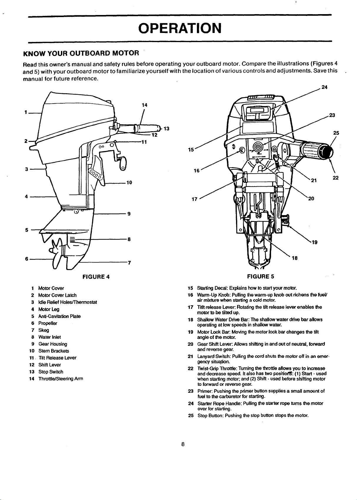
OPERATION
KNOW YOUR OUTBOARD MOTOR
Read this owner's manual and safety rules before operating your outboard motor. Compare the illustrations (Figures 4
and 5) with your outboard motor to familiarize yourself with the location of various controls and adjustments. Save this
manual for future reference.
14
2
OO
15
25
FIGURE 4
1 MotorCover
2 MotorCoverLatch
3 IdleReliefHolesfThermostat
4 MotorLeg
5 Anti-CavitationPlate
6 Propeller
7 Skeg
8 WaterInlet
9 GearHousing
10 Stem Brackets
11. "131tReleaseLever
12 ShiftLever
13 StopSwitch
14 ThrotUe/SteedngArm
- 10
22
17
9
18
FIGURE 5
15 StartingDecal:Explains howtostartyourmotor.
16 Warm-Up Knob:Puffingthewarm-upknoboutrichensthe fuel/
airmixture whenstartingacoldmotor.
17 "ritltreleaseLever:Rotatingthe tiltreleaseleverenables the
motorto be tiltedup.
18 ShallowWaterDriveBar:The shallowwaterdrivebarallows
operatingat lowspeedsinshallowwater.
19 MotorLockBar:Movingthe motorlockbarchangesthe tilt
angleof themotor.
20 GearShiftLever:Allowsshiftinginand outof neutral,forward
andreversegear.
21 LanyardSwitch:Pullingthecordshutsthe motoroffinan emer-
gencysituation.
22 Twist-GripThrottle:Tumingthethrottleallowsyou toincrease
anddecreasespeed.Italsohastwopositiod_:(1) Start - used
whenstartingmotor;and (2)Shift -usedbeforeshiftingmotor
toforward orreversegear.
23 Primer:Pushingtheprimerbuttonsuppliesa smallamountof
fueltothecarburetorforstarting.
24 StarterRopeHandle:Pullingthe starterropeturns the motor
overforstarting.
25 StopButton:Pushingthestopbuttonstopsthe motor.
8
OPERATION
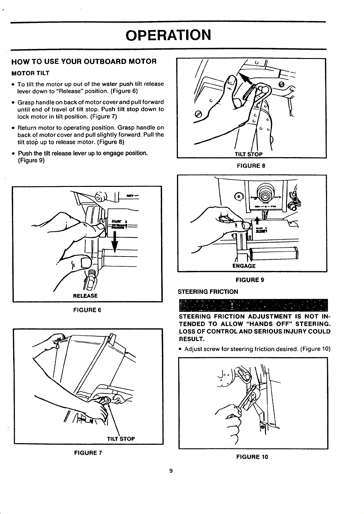
HOW TO USE YOUR OUTBOARD MOTOR
MOTOR TILT
• To tilt the motor up out of the water push tilt release
lever down to "Release" position. (Figure 6)
• Grasp handle on back of motor cover and pull forward
until end of travel of tilt stop. Push tilt stop down to
lock motor in tilt position. (Figure 7)
• Return motor to operating position. Grasp handle on
back of motor cover and pull slightly forward. Pull the
tilt stop up to release motor. (Figure 8)
• Push the tilt release lever up to engage position.
(Figure 9)
RELEASE
FIGURE 6
TILTSTOP
FIGURE 8
ENGAGE
FIGURE 9
STEERING FRICTION
STEERING FRICTION ADJUSTMENT IS NOT IN-
TENDED TO ALLOW "HANDS OFF" STEERING.
LOSS OF CONTROL AND SERIOUS INJURY COULD
RESULT.
• Adjust screw for steering friction desired. (Figure 10)
FIGURE 7
TILT STOP
FIGURE 10
J
ii i i
OPERATION
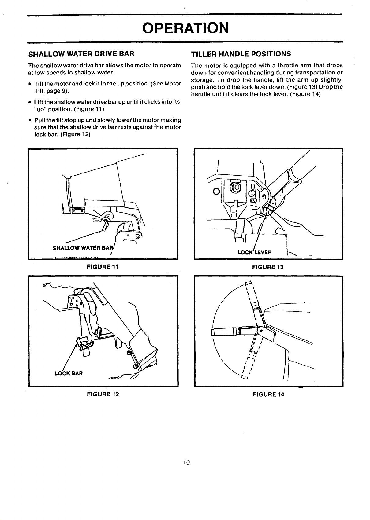
SHALLOW WATER DRIVE BAR
The shallow water drive bar allows the motor to operate
at low speeds in shallow water.
• Tilt the motor and lock it in the up position. (See Motor
Tilt, page 9).
• Lift the shallow water drive bar up until it clicks into its
"up" position. (Figure 11)
• Pull the tilt stop up and slowly lower the motor making
sure that the shallow drive bar rests against the motor
lock bar. (Figure 12)
TILLER HANDLE POSITIONS
The motor is equipped with a throttle arm that drops
down for convenient handling during transportation or
storage. To drop the handle, lift the arm up slightly,
push and hold the lock lever down. (Figure 13) Drop the
handle until it clears the lock lever. (Figure 14)
SHALLOW WATER BAR/
FIGURE 11
LOCK BAR
FIGURE 12
/
FIGURE 13
f\\
/
\
FIGURE 14
10
OPERATION
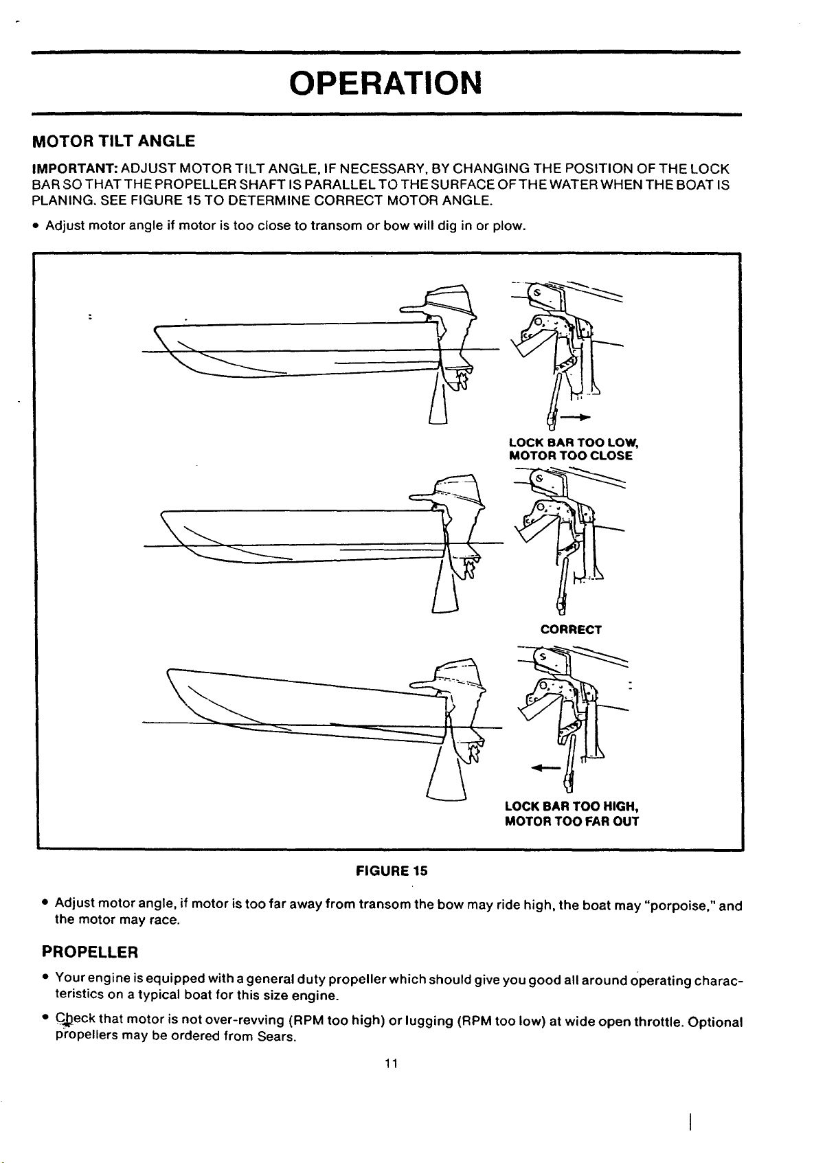
MOTOR TILT ANGLE
IMPORTANT: ADJUST MOTOR TILT ANGLE, IF NECESSARY, BY CHANGING THE POSITION OF THE LOCK
BAR SO THAT THE PROPELLER SHAFT IS PARALLEL TO THE SURFACE OF THE WATER WHEN THE BOAT IS
PLANING. SEE FIGURE 15 TO DETERMINE CORRECT MOTOR ANGLE.
• Adjust motor angle if motor is too close to transom or bow will dig in or plow.
LOCK BAR TOO LOW,
MOTOR TOO CLOSE
-2
CORRECT
LOCK BAR TOO HIGH,
MOTOR TOO FAR OUT
FIGURE 15
• Adjust motor angle, if motor is too far away from transom the bow may ride high, the boat may "porpoise," and
the motor may race.
PROPELLER
• Your engine is equipped with a general duty propeller which should give you good all around Operating charac-
teristics on a typical boat for this size engine.
• CJ_eck that motor is not over-revving (RPM too high) or lugging (RPM too low) at wide open throttle. Optional
propellers may be ordered from Sears.
11
OPERATION
BEFORE STARTING ENGINE
OIL SELECTION
• Use NMMA certified TC-W3 or TC-W II outboard oil.
GASOLINE SELECTION
• 87 pump octane minimum, premium not needed.
• 10% ethanol maximum.
• 3% methanol maximum.
• Use a major fuel supplier.
IMPORTANT: Experience indicates that alcohol
blended fuels (called gasohol or using ethanol or
methanol) can attract moisture which leads to separa-
tion and formation of acids during storage. Acidic gas
can damage the fuel system of an engine while in stor-
age. To avoid engine problems, the fuel system should
be emptied before storage for 30 days or longer. Drain
the gas tank, start the engine and let it run until the fuel
lines and carburetor are empty. Use fresh fuel next
season. See Storage Instructions for additional infor-
mation. Never use engine or carburetor cleaner pro-
ducts in the fuel tank or permanent damage may occur.
FOR A PROPER FUEL MIX
Recommended lubricant and gasoline must be properly
mixed or serious damage will result to the engine.
• Maintain a clean fuel tank.
• Strain fuel through a fine mesh strainer.
• Pour one (1) gallon (38.1 cm) of fresh gasoline intoan
empty fuel tank. Add proper amount of outboard mo-
tor oil. Add balance of gasoline, mix thoroughly.
TO PREVENT SPILLING FUEL IN BOAT, REMOVE
PORTABLE FUEL TANK WHEN REFUELING. GASO-
LINE IS HIGHLY FLAMMABLE -- ALWAYS MIX IN
WELL VENTILATED AREA.
• Observe safety rules - mix fuel in a well ventilated
area (preferably outdoors). Avoid sparks and open
flames.
• Repeated use of additive compounds such as
"break-in" oils, "tune-up" compounds, "tonics", "fric-
tion reducing" compounds, etc. is not recommended.
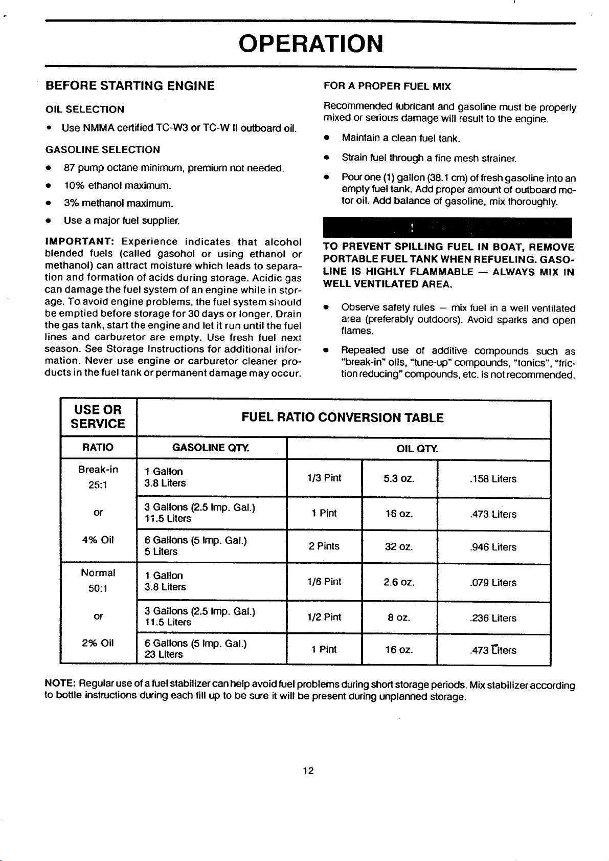
USE OR
SERVICE FUEL RATIO CONVERSION TABLE
RATIO GASOLINE QTY. OIL QTY.
Break-in 1Gallon
25:1 3.8 Liters 1/3 Pint 5.3 oz, .158 Liters
or 3 Gallons (2.5 Imp. Gal.)
4% Oil 6 Gallons (5 Imp. Gal.)
Normal 1 Gallon
50:1 3.8 Liters 1/6 Pint 2.6 oz. .079 Liters
or 3 Gallons (2.5 Imp. Gal.) 1/2 Pint 8 oz. .236 Liters
2% Oil 6 Gallons (5 Imp. Gal.)
NOTE: Regular use of a fuel stabilizer can help avoid fuel problems during short storage periods. Mix stabilizer according
to bottle instructions during each fill up to be sure it will be present during unplanned storage.
11.5 Liters 1Pint 16 oz. .473 Liters
5 Liters 2 Pints 32 oz. .946 Liters
11.5 Liters
23 Liters 1 Pint 16 oz. .473 "Citers
12
• II II I
I
OPERATION
BREAK-IN PROCEDURE -- USE 25:1 MIX
I ,A CAUTION ]
SEVERE DAMAGE TO THE ENGINE CAN RESULT
BY NOT COMPLYING WITH THE FOLLOWING
BREAK-IN PROCEDURE.
• Mix correct amount of outboard motor oil with each
gallon of gasoline (see gasoline -- oil mixture require-
ments and fuel ratio conversion table).
• Run engine at moderate speed (approximately 1/2
throttle) for ten minutes. Check operation of the
water pump and cooling system. (Refer to "Checking
Water Pump Operation.")
• Advance to full throttle for a few seconds.
• Return to moderate speed for several minutes.
• Repeat steps 2 and 3 gradually increasing time of full
throttle operation until 5 minutes of full throttle oper-
ation has been reached. This break-in operation will
require approximately one (1) hour running time.
• Use the 25:1 gasoline-oil for an additional two (2)
hours before changing to the 50:1 mixture for normal
use.
• AVOID CONTINUOUS FULL THROTTLE OPERA-
TION FOR AN ADDITIONAL TWO (2) HOURS.
• Your outboard motor may now be operated at any
throttle setting desired using the proper fuel ratio as
specified in the gasoline-oil chart.
DISCONNECT FUEL LINE IF MOTOR IS NOT USED
FOR ANY LENGTH OF TIME. FAILURE TO DO SO
COULD RESULT IN FUEL LEAKAGE INTO THE
BOAT.
• Observe required maintenance and operating in-
structions.
FUEL SYSTEM
I _ CAUTION 1
CHECK WITH YOUR SEARS STORE BEFORE USING
ANY FUEL TANK; TO MAKE SURE THE LINE, VENT
AND CHECK VALVE ARE SAFE, AND ARE THE
CORRECT SIZE.
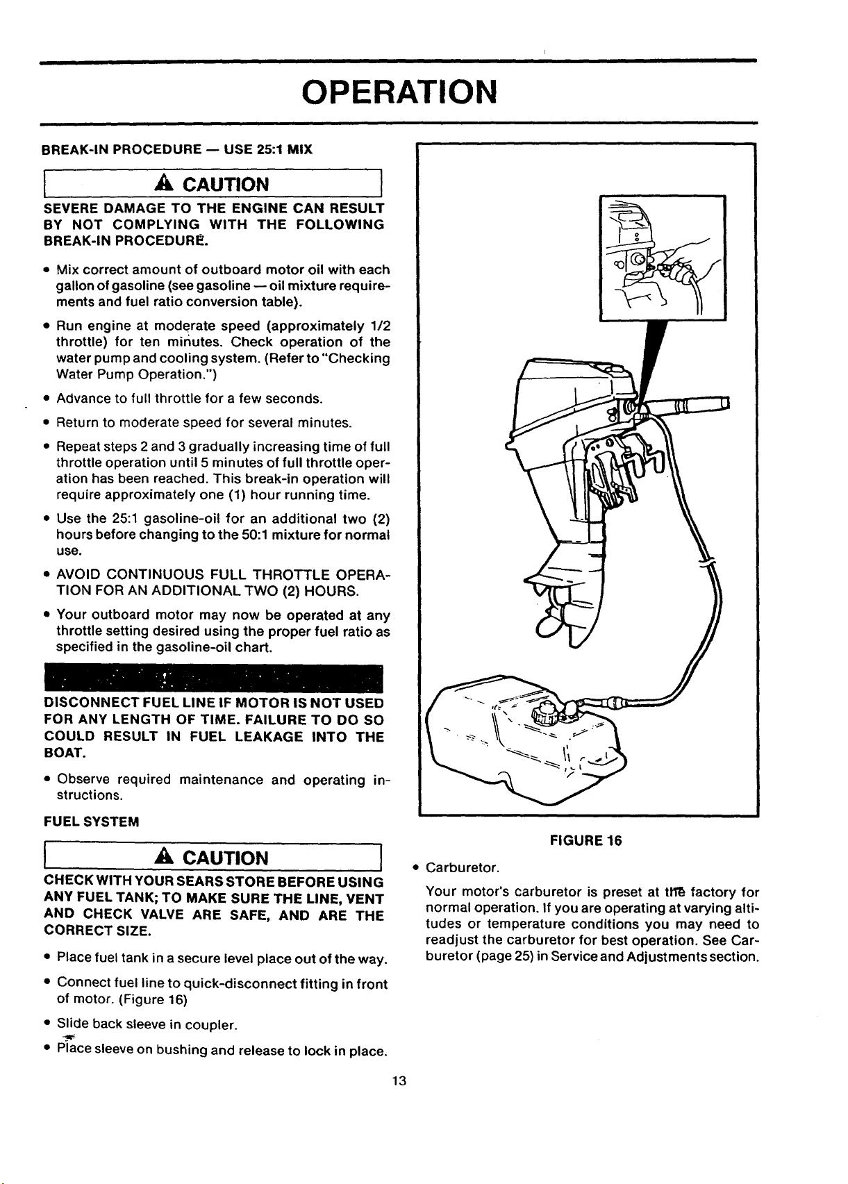
• Place fuel tank in asecure level place out of the way.
• Connect fuel line to quick-disconnect fitting in front
of motor. (Figure 16)
FIGURE 16
• Carburetor.
Your motor's carburetor is preset at tll_ factory for
normal operation. If you are operating at varying alti-
tudes or temperature conditions you may need to
readjust the carburetor for best operation. See Car-
buretor (page 25) in Service and Adjustments section.
• Slide back sleeve in coupler.
• Place sleeve on bushing and release to lock in place.
13
OPERATION
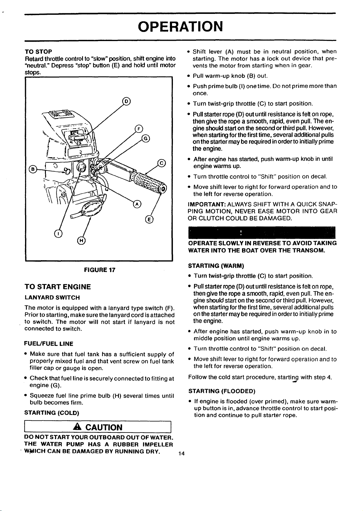
TO STOP
Retard throttle control to "slow" position, shift engine into
"neutral." Depress "stop" button (E) and hold until motor
stops.
®
• Shift lever (A) must be in neutral position, when
starting. The motor has a lock out device that pre-
vents the motor from starting when in gear.
• Pull warm-up knob (B) out.
• Push prime bulb (I) onetime. Do not prime more than
once.
• Turn twist-grip throttle (C) to start position.
• Pull starter rope (D) out until resistance isfelt on rope,
then give the rope a smooth, rapid, even pull. The en-
gine should start on the second or third pull. However,
when starting for the first time, several additional pulls
on the starter may be required inorder to initially prime
the engine.
• After engine has started, push warm-up knob in until
engine warms up.
• Turn throttle control to "Shift" position on decal.
• Move shift lever to right for forward operation and to
the left for reverse operation.
IMPORTANT: ALWAYS SHIFT WITH A QUICK SNAP-
PING MOTION, NEVER EASE MOTOR INTO GEAR
OR CLUTCH COULD BE DAMAGED.
FIGURE 17
TO START ENGINE
LANYARD SWITCH
The motor is equipped with a lanyard type switch (F).
Prior to starting, make sure the lanyard cord is attached
to switch. The motor will not start if lanyard is not
connected to switch.
FUEL/FUEL LINE
• Make sure that fuel tank has a sufficient supply of
properly mixed fuel and that vent screw on fuel tank
filler cap or gauge is open.
• Check that fuel line is securely connected to fitting at
engine (G).
• Squeeze fuel line prime bulb (H) several times until
bulb becomes firm.
STARTING (COLD)
OPERATE SLOWLY IN REVERSE TO AVOID TAKING
WATER INTO THE BOAT OVER THE TRANSOM.
STARTING (WARM)
• Turn twist-grip throttle (C) to start position.
• Pullstarter rope (D) out until resistance isfelt on rope,
then give the rope a smooth, rapid, even pull. The en-
gine shouldstart on the second or third pull. However,
when startingfor the firsttime, several additional pulls
on the starter may be required in order to initiallyprime
the engine.
• After engine has started, push warm-up knob in to
middle position until engine warms up.
• Turn throttle control to "Shift" position on decal.
• Move shift lever to right for forward operation and to
the left for reverse operation.
Follow the cold start procedure, starting with step 4.
STARTING (FLOODED)
• If engine is flooded (over primed), make sure warm-
up button is in, advance throttle control to start posi-
tion and continue to pull starter rope.
[ A, CAUTION
DO NOT START YOUR OUTBOARD OUT OF WATER.
THE WATER PUMP HAS A RUBBER IMPELLER
• WJblICH CAN BE DAMAGED BY RUNNING DRY.
14
OPERATION
OPERATING CHECKS
COOLING SYSTEM
Cooling water ispicked up on the side ofthe gear housing
just ahead of the propeller, goes through the powerhead,
and then goes out with the exhaust gases.
IMPORTANT: NEVER RUN MOTOR OUT OF THE WA-
TER, AND NEVER RUN MOTOR UNLESS WATER PUMP
IS WORKING NORMALLY OR OVERHEATING AND MO-
TOR DAMAGE MAY RESULT.
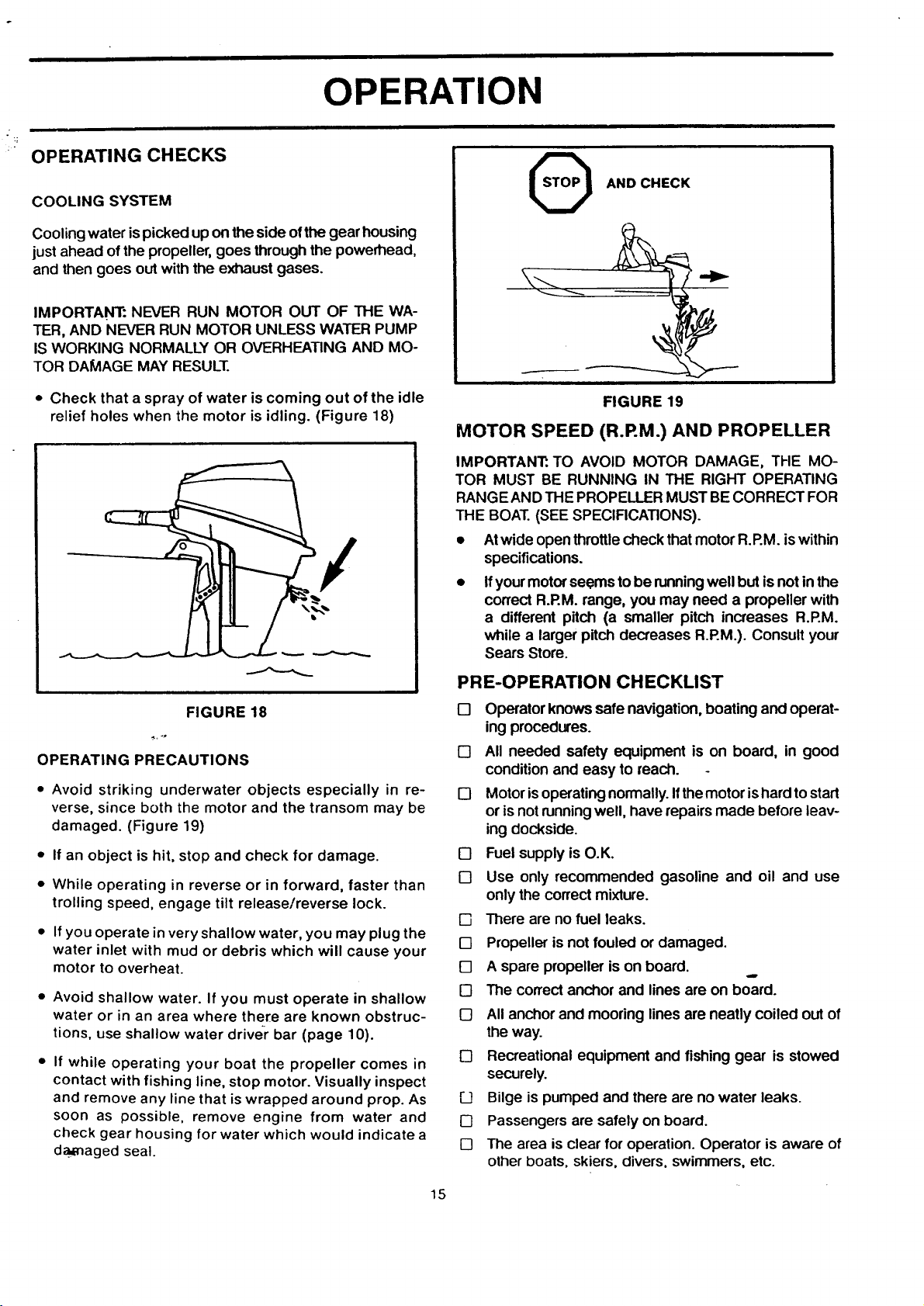
• Check that a spray of water is coming out of the idle
relief holes when the motor is idling. (Figure 18)
/
AND CHECK
i
FIGURE 19
MOTOR SPEED (R.RM.) AND PROPELLER
IMPORTANT:. TO AVOID MOTOR DAMAGE, THE MO-
TOR MUST BE RUNNING IN THE RIGHT OPERATING
RANGE AND THE PROPELLER MUST BE CORRECT FOR
THE BOAT.(SEE SPECIRCATIONS).
• Atwide open throttlecheck that motor R.P.M. iswithin
specifications.
• Ifyour motorseems to be runningwell but is not in the
correct R.RM. range, you may need a propeller with
a different pitch (a smaller pitch increases R.P.M.
while a larger pitch decreases R.RM.). Consult your
Sears Store.
FIGURE 18
OPERATING PRECAUTIONS
Avoid striking underwater objects especially in re-
verse, since both the motor and the transom may be
damaged. (Figure 19)
If an object is hit, stop and check for damage.
While operating in reverse or in forward, faster than
trolling speed, engage tilt release/reverse lock.
If you operate in very shallow water, you may plug the
water inlet with mud or debris which will cause your
motor to overheat.
Avoid shallow water. If you must operate in shallow
water or in an area where there are known obstruc-
tions, use shallow water driver" bar (page 10).
If while operating your boat the propeller comes in
contact with fishing line, stop motor. Visually inspect
and remove any line that is wrapped around prop. As
soon as possible, remove engine from water and
check gear housing for water which would indicate a
da_naged seal.
PRE-OPERATION CHECKLIST
13 Operator knows safe navigation, boating and operat-
ing procedures.
[] All needed safety equipment is on board, in good
condition and easy to reach.
[] Motor isoperatingnormally.Ifthemotorishard tostart
or is not runningwell, have repairs made before leav-
ing dockside.
[] Fuel supply is O.K.
[] Use only recommended gasoline and oil and use
only the correct mixture.
[] There are no fuel leaks.
[] Propeller is not fouled or damaged.
[] A spare propeller is on board.
[] The correct anchor and lines are on board.
[] All anchor andmooring lines are neatly coiled out of
the way.
[] Recreational equipment and fishing gear is stowed
securely.
F__]Bilge is pumped and there are no water leaks.
[] Passengers are safely on board.
[] The area is clear for operation. Operator is aware of
other boats, skiers, divers, swimmers, etc.
Ip
15
OPERATION
SHAKEDOWN CHECKLIST
[] Operator has read and understood the entire opera-
tor's manual.
[] Operator has carried out pre-operation checklist.
[] Operate cautiously and get to know how your boat
handles.
[] If the motor is new, follow all break-in procedures.
[] Follow all operating procedures.
[] Check tightness of mounting clamps.
[] Adjust motor angle if necessary.
[] Adjust idle if necessary.
[] Adjust carburetor if necessary.
[] Check that propeller is correct for boat.
OPERATING IN FREEZING
TEMPERATURES
• When usingthe motor infreezing or nearfreezing tem-
peratures, keep the gear housing inthe water. When
launching the boat/motor in near freezing"tempera-
tures, let the rig soak for 20 to 30 minutes before start-
ing to allow water in the water pick-up, water pump,
or water tube to thaw.
IMPORTANT: IF THE MOTOR IS TILTED OUT OF THE
WATER, WATER REMAINING IN THE COOLING SYSTEM
AND GEAR HOUSING MAYFREEZE AND CAUSE PARTS
TO BREAK.
• Do not starta motor that might be frozen.
SALT WATER OPERATION
Although all motor parts that contact water have been
chemically treated to resist salt water corrosion, you
should take some special steps after runningyour motor
in salt water.
• Always tilt the motor out of thewater when not inuse.
• From time to time run the motor infresh water to flush
out salt deposits.
• Wash motor down with fresh water and soap; rinse.
Apply a marine-type wax to protect the finish.
• Periodically remove propeller and lubricatepropeller
shaft.
• Replace water pump impeller every year. Apply anti-
seize compound to the driveshaft/crankshaft spline.
i ,A CAUTION
IF OUTBOARD IS STORED TILTED UP IN FREEZING
TEMPERATURE, TRAPPED COOLING WATER OR
RAIN WATER THAT MAY HAVE ENTERED THE
EXHAUST OUTLET IN THE GEAR CASE COULD
FREEZE AND CAUSE DAMAGE TO THE OUTBOARD.
16
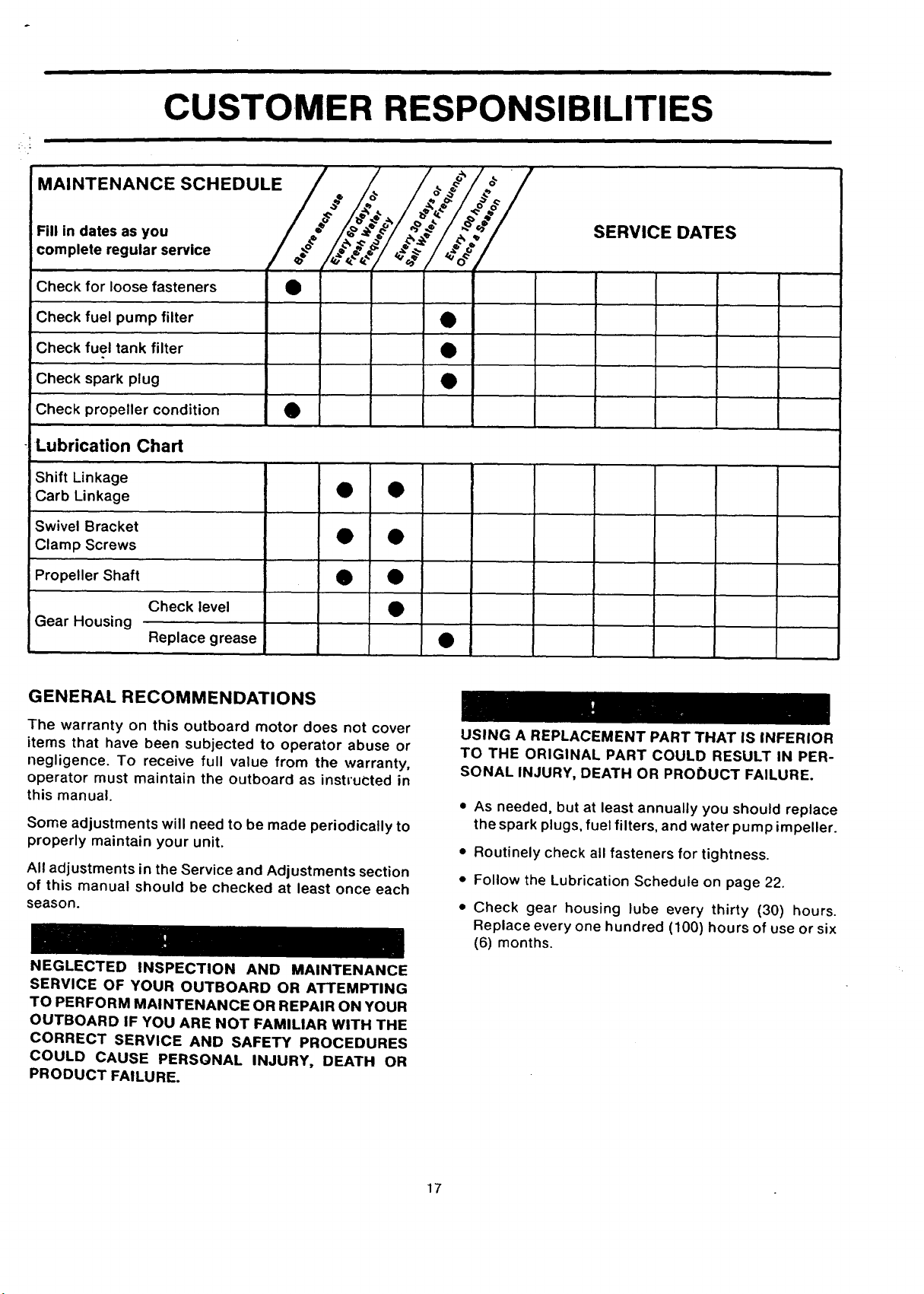
CUSTOMER RESPONSIBILITIES
' / / _/_ /
MAINTENANCE SCHEDULE/ ._ /.o,. / ._j/_o_.# /
F.,,._atesas.o,, I/' _;_lt._f l_"._t ..:#I/'&"'!.&_'!
complete regular service / ._o- /
Check for loose fasteners •
Check fuel pump filter •
Check fuel tank filter •
Check spark plug •
Check propeller condition •
Lubrication Chart
Shift Linkage
Carb Linkage • •
Swivel Bracket
Clamp Screws • •
Propeller Shaft • •
Check level •
Gear Housing
Replace grease •
SERVICE DATES
GENERAL RECOMMENDATIONS
The warranty on this outboard motor does not cover
items that have been subjected to operator abuse or
negligence. To receive full value from the warranty,
operator must maintain the outboard as instructed in
this manual.
Some adjustments will need to be made periodically to
properly maintain your unit.
All adjustments in the Service and Adjustments section
of this manual should be checked at least once each
season.
NEGLECTED INSPECTION AND MAINTENANCE
SERVICE OF YOUR OUTBOARD OR ATTEMPTING
TO PERFORM MAINTENANCE OR REPAIR ON YOUR
OUTBOARD IF YOU ARE NOT FAMILIAR WITH THE
CORRECT SERVICE AND SAFETY PROCEDURES
COULD CAUSE PERSGNAL INJURY, DEATH OR
PRODUCT FAILURE.
USING A REPLACEMENT PART THAT IS INFERIOR
TO THE ORIGINAL PART COULD RESULT IN PER-
SONAL INJURY, DEATH OR PRODUCT FAILURE.
• As needed, but at least annually you should replace
the spark plugs, fuel filters, and water pump impeller.
• Routinely check all fasteners for tightness.
• Follow the Lubrication Schedule on page 22.
• Check gear housing lube every thirty (30) hours.
Replace every one hundred (100) hours of use or six
(6) months.
17
 Loading...