

Page 1
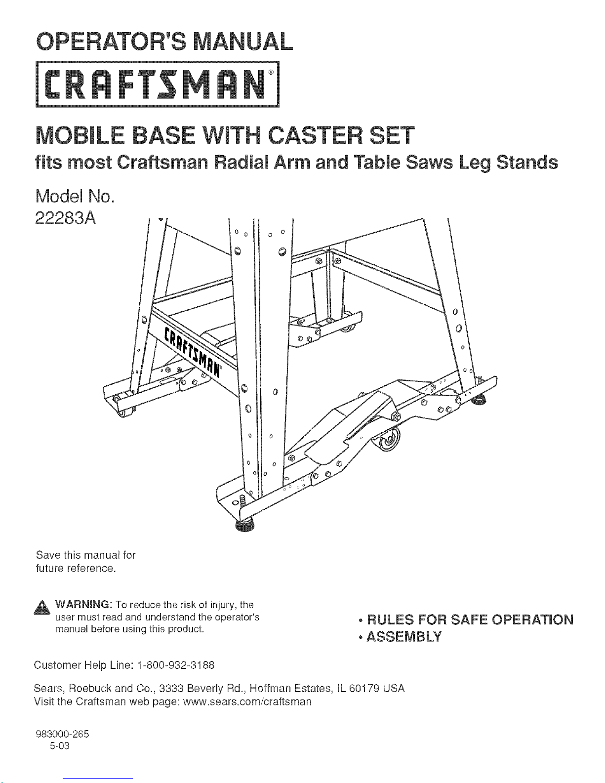
fits most Craftsman
Model No.
22283A
Radial Arm and Table Saws Leg Stands
©
Save thb manual for
future reference.
,_ WARNING: To reduce the risk of injury, the
user must read and understand the operator's
manual before using this product.
oRULES FOR SAFE OPERATION
oASSEMBLY
Customer Help Line: 1-800-932-3188
Sears, Roebuck and Co., 3333 Beverly Rd., Hoffman Estates, IL 60179 USA
Vbit the Craftsman web page: www.sears.com/craftsman
983000-265
5-03
Page 2
Thepurposeof safetysymboisis to attractyourattentionto possibiedangers.Thesafetysymbois,andthe
expianafionswiththem,deserveyourcarefuiattentionandunderstanding.Thesafetywarningsdonotbythemseives
eliminateanydanger.Theinstructionsorwarningstheygivearenotsubstitutesforproperaccidentprevention
measures.
SYMBOL MEANmNG
DANGER:hdbatesanimminentiyhazardoussituation,which,if notavoided,wHiresuitindeathor
WARNING:Undbatesapotentialiyhazardoussituation,which,ifnotavoided,couidresuitindeathor
seriousinjury.
CAUTION:Indicatesa potentiallyhazardoussituation,which,ifnotavoided,mayresultinminoror
moderateinjury.Itmayalsobeusedtoalertagainstunsafepracticesthatmaycausepropertydamage.
mmportant:Advisesyouofimportantinformationorinstructionsvitaltotheoperationormaintenanceof
Note:Advisesyouofadditionalinformationconcerningtheoperationormaintenanceoftheequipment.
,_ WARNmNG: Read and understand aH instructions.
Failure to follow all instructions listed below, may
result in electric shock, fire and/or serious personal
injury.
SAVE THESE INSTRUCTIONS
[] Know your power tool Read the operator's manuai for
your Table Saw or Radial Arm Saw carefully. Learn the
saw's applications and limitations as well as the specific
potential hazards related to this tool.
Safety instructions For Mobile Bases
[] Never install mobile base with saw mounted to leg
stand.
[] Be careful when moving to avoid any finger pinch
points.
[] Remove the dust bag before moving the tool or when
placing the leg stand on the mobile base.
[] Place base on a level surface and adjust leveling feet
before placing your saw in position. This should keep
saw from rocking, while testing it for stability.
[] Test for stability in both the up (on the caster) and the
down positions. Exercise caution when testing the
stability of top heavy machines such as your saw.
[] Never lift the saw onto the leg stand without help.
[] Unplug your saw before moving or repositioning your
tool.
[] Always test your setup for stability and safety after
repositioning and before plugging the saw into an outlet.
[] Care should be taken when planning the orientation of
your saw onto the mobile base. Transfer of weight off of
the leveling feet to the caster will result in the saw tilting
1/2 in. toward the fixed wheels. When repositioning top
heavy tools such as your saw, take advantage of the
center of gravity, and position so that it will remain
stable while on caster.
[] Never use your saw while it is suspended on the swivel
caster. Always lower saw onto the nonskid leveling feet
before operating.
[] When moving, always push the leg stand, not the saw.
[] Think Safety. Safety is a combination of operator
awareness, common sense and alertness at aii times.
[] Save these instructions. Refer to them frequently and
use them to instruct others who may use this tool If you
loan someone this tool, loan them these instructions also.
_ WARNING: Secure leg stand to mobile base before
moving the tool. Failure to secure the leg stand could
cause the saw to fall resulting in serious personal
injury.
[] Measure the leg stand from the leveling foot hobs at
one side to the leveling foot hobs on the other side.
This measurement is needed to determine which hobs
in the lower support bracket and wheel support bracket
are to be used when assembling the mobile base. The
hobs must align properly for the leg stand and mobile
base to be secured.
_, WARNING: Do not engage or disengage the
release lever while the support brace is still attached
to the leg stand and never use your hand to operate
the release lever. Failure to heed this warning could
result in serious personal injury.
[] Unpack and identify all components and hardware
before attempting to assemble this unit.
Page 3

The items incUuded in this kit are:
m Large caster (1)
m Oenter support (2)
m Lower support bracket (2)
m WheeU support bracket (2)
m Oaster bracket (1)
m Release Rever (1)
WheeU Hardware Bag:
m WheeU (2)
m Hex bout, 1/4x 1 3/4 (2)
m Lock nut, 1/4 - 20 (2)
m Large bout, 3/8 x 4 1/2 (1)
m Washer, 3/8 (1)
m Lock nut, 3/8 - 16 (1)
Hardware Baq:
m Hex bout, 1/4 x 5/8 (24)
m Hex nut, flanged, 1/4 - 20 (24)
m Large hex bout, 5/16 x 3/4 (10)
m Large hex nut, 5/16 - 18 (8)
m Washer, 5/16 (18)
m LeveUing feet (2)
m Washer, 3/8 (4)
m Nut, 3/8-16(4)
m Lock nut, 5/16 - 18 (2)
MOSTTABLE
SAWS
MOSTRADIAL
ARMSAWS
CENTER
SUPPORT
WHEEL
SUPPORT
BRACKET
_° ° ° ooO_
WHEEL
WHEEL RELEASELEVER
SUPPORTBRACKET @_%\
WHEEL
CENTER
LOWER ÷ !41
SUPPORT ...__[%/
BRACKET °°°_--
_._ LEVEUNG
® FEET
LOWERSUPPORT
BRACKET
®
@
@
CASTER
BRACKET
LEVEUNGFEET
LARGECASTER
Fig. 1
Page 4

ASSEMBLY (NSTRUCT(ONS
To assemble first side (side with two wheels):
m Remove wheels, hex bolts, and lock nuts from the bag.
m Place wheel in slot of the wheel support bracket and
insert hex bolt through both the bracket and the wheel.
[] Secure with the lock nut and tighten.
[] Place center support (without the slot) upside down on
a fiat surface. Align the wheel support brackets with the
hobs previously determined to fit the saw. Using the
small hex bolts and hex nuts from the hardware bag,
place hex bolts through the hobs of both the wheel
support bracket and the center support.
[] Tighten using hex nuts.
Note: Repeat above steps for other side.
To assemble remaining side (side with two leveling feet
and caster):
m Mount caster to the caster bracket using large hex
bolts. Secure using lock nuts.
m Attach leveling feet to lower support bracket using hex
nuts and washers as shown in figure 3. Leveling feet
must touch the floor when the caster is in the raised
position.
m Secure bracket to underside of center support using the
remaining large hex bolts and hex nuts.
m Place center support (with slot and attached caster)
upside down on a fiat surface. Align the lower support
brackets with the hobs previously determined to fit the
saw. Using the small hex bolts and hex nuts from the
hardware bag, place hex bolts through the hobs of
both the lower support bracket and the center support.
[] Tighten using hex nuts.
[] Turn assembly upright onto leveling feet.
[] (nsert release lever into slot. Using the large bolt,
washer, and lock nut, secure release lever. Tighten.
[] (f saw is mounted to a leg stand, remove the saw from
the leg stand before installing the mobile base.
[] Remove leveling feet from leg stand. Secure the mobile
base to the leg stand using the large hex bolt and large
hex nut.
[] Mount the saw and remove support brace from the leg
stand (the support above the release lever). Do not
discard the support brace and hardware. (n the event
the saw is ever removed from the mobile base the
support brace must be installed.
,_ WARN(NG: Obtain help when lifting the saw to
place on the leg stand. Once the saw is mounted,
remove the support brace from the leg stand (the
support above the release lever). Failure to remove
the support brace, could result in injury.
TO RA(SE WHEEL:
Step down firmly on release lever.
TO LOWER WHEEL:
Place foot under the release lever and lift up.
Note: Never use your hand to raise or lower the wheel.
CENTERSUPPORT HEXBOLT
HEXHUT,
FLANGED_
HEXBOLT
_WHEEL
SUPPORTBRACKET
LOCKNUT
WHEEL
LARGEBOLT
J
LOCKHUT
WHEEL
Fig. 2
RELEASE
LEVER
WA_
NUT
@
@
SLOT
LOCKNUT
CASTER
BRACKET
LARGE
HEXBOLT_WASHER CASTER
HEXNUT
LEVEUNGFEET
TO
RA(SE
LARGE
HEXBOLT
&
Fig. 3
TO
Fig. 4
 Loading...