


Operators Manual
CRIIFTSMIIN°
Adjustable Universal
MOBILE BASE
Model No. 22252
• Safety
• Assembly
• Operation
• Parts
CAUTION:
Before using this product,
read this manual and follow
all its Safety Rules and
Operating Instructions.
Sears, Roebuck and Co., Hoffman Estates, IL 60179 U.S.A.
Visit ourCraftsman website:www.sears.com/craftsman
General Safety Instructions for Power Tools
U_ng powertod_ of any kk_lcan bedangerousif safe opera,rigproceduresare
noflolowed. Recogn_ tbehaza_s _ eachtoc_andusng themwith respect
and cau_xw,_ll co_ imit tbe pcssibailyofpemc,'_ lejury. _, if
_fely p_au_ns am igno_l, personaliniufy_1_ukaly result.Alwaysusecon_
m0nseine - your pemonlesofelyle your_spc_==Jt_ity
I. Knowyourpowertobl. Fieadand understandlhe Owners Manual and
_ mewarr_gsand_nswcUon_be_sarlXed_otbetcd.
Propedygromd_ tods.
3. Keepgua_slep_ce.
4. Flen!o_eadjus_ngkeysand wrenches.
5. l<eepwod<area c_eanandd_
6. Keepchi_Venaway.
7. Neverleave ham;rigmachines,t:_<_unattendnd.
8. Dleconneclto_s from se_qce.
9. Begulady rnainie_ too_s.
10.LBe conact toolslot thejob.
11.New'force a tod.
12.v_arsa_yappe_.
13.u_ s_y g_assesOogg_.
15.Rep_cebemaged_ Vnrnnd_ely
16.Ma_ sum yourwch<p_tfc_n L_suff_ sturdyto doIbe
med_cjchatbend.
17. Usepo_w_tools _ a we_llitareawttha k_ surfaceonwhichto stand tbetis
dean andfree Imm anyobl_tk_.
18.o_ng*orkpiecesecur_y.
16. Prc_oedya_cho_powertoolsto w_k siends.
20. Useco_ectblade_r jobberg done.
21."1111nkSafe. Sa_ofyisa combina_onofoperatorawareness,commo_sense
and _r_ess atedl_nes.
Safety Instructions for Mobile Bases
1. Be caretulwben nxMng to Imit a_'_yr*_gerpinchpo_ts.
2- P_e bese w a iove_sv_ace and a_t_ levele_ belo_ p_:=_ the vr_k_e in
p_Ben. TI_ sttouUkeep Ibe_ _m roddng,v,t_e ios_ng _for sblt_.
3. Testfor stabililyin both_e up (on_e castors)and the do,m positions.
_ cau_o_,,,A_entostingthe sblbahyoft_p heavymac_nes (ditil
Ixesses, bandsaws, e_c,).
4. Un_ug any powerto_ beforemow_ or_ng your toot
5. A_ tost yoursetup forsieb_ityandsafelya_er mpos_oblng.
Cam chould be taken wbenpbnrmg Ibe odenta_ of tbe machineoofothe
univ_ rno_ bese.Tmn_ of_eiQ_to_ofthe_/elersto_he_ v_l
resultin_e machiee fiBeg 1/2"towardthe tixndwhets. Wben posit_o_ng
top heavytoole suchas a ditgpressorb_mdsaw,takendvant_ge oftbe o_-
terof gmv6y,=xI positionso thatItwil rem_n _ whileoncasters.
7. Ne_e_useyourmachinewhileit issuspendedon thetwo swivelcastem.
N_ys lowertbe_ oofo6_eno_ddd k_elers beforeopera_g.
e. _ mov,ng,=_,,,,six_-,_ebase,notthemchlee.
Assembly Instructions
Toolsrequired:7/16", 1i'Z',9/16_wrench, 7/16" soc_ tape rr_asure, pliers.
1. Unpack and identifyail componentsand hardware. Make sure there are
no m_sing ber_ and t_ them le noShil_oingbernage.
Note: Read instructic_sthoroughlybefore proceeding.
2. Carefully measure tbe footprint of your machlee(orwhatover you are
md_l_dng) and add about 1"to tbe dime_. (1" bllows dea_ tor
the fasteners), Keep in mindthe baseadjusts in 1"increments.
Note: Mostmacblnesw_th4-ioggndstandsare sornewbetndj_cabie, by
Iooseflingand mtightening1heboRsthat holdtbem together.
3. Firsten._,umthe machinele stable onthe mobliebase, then determtoe
_rect_n of ro=.Carefu_ reviow assemUy _ chown below toheko
you _ the fixedwheel, c_sterand ieveler p_ement. As theseam
exampiosonly, you mustdetermine what bestsuitsyourpadleofar
marine's requirementsfor stability.
4. Select and anange tbeSide Railsizes as necessaryto assembie Ihe
base to your machine's footprint.
Note: Ifbe4pto liltyourmacblne intotbe bese le notavailabie, you may
want toassemble tbe base aroundyourmachlee. Use 2 x 4's to
blockthe machineup.
5. Bolfthe Side Rai_sto thecomers and each other usingthese simple
rules:
A: AIJconnectionsrequire_e use of (2) 1/4"-20 x 1/2"bolts(Q) and
(2) 1/4"-20 nuts (R) at each end ofthe connections.
B: PositionSideRails intocomers asfar as ispractical.
C: Itle recommended you keepyourmachiee stand symmetrical by
usingtbe sarnesize and posi6oblngof Side Rails on opposite sides.
Note: blsert boltsso thsttbe nutsare on tbeinsideof the
movie base.
6. Re-check dimenstons,_en _hten all boitsand nuts.
Assembly Examples
Be sure to fof_w safely and Assembly Instructions.Keep in mind the actual
operation ofyour machine and the effect it has on overall stabilit_
Figure 1 Figure 2
A wide, narrowb_se, suchas on _t edge
sander, may berm_ from th_ amangement.
Figure 3
Badcallysquaremaddne_canbear_nged
A k:_g,narrow base, such M c_ a jointer,
wouldbe_e_t thornb_s anarq3,ecnent.
Figure 4
A_'_, nanowbase,suchasona_1, pre_
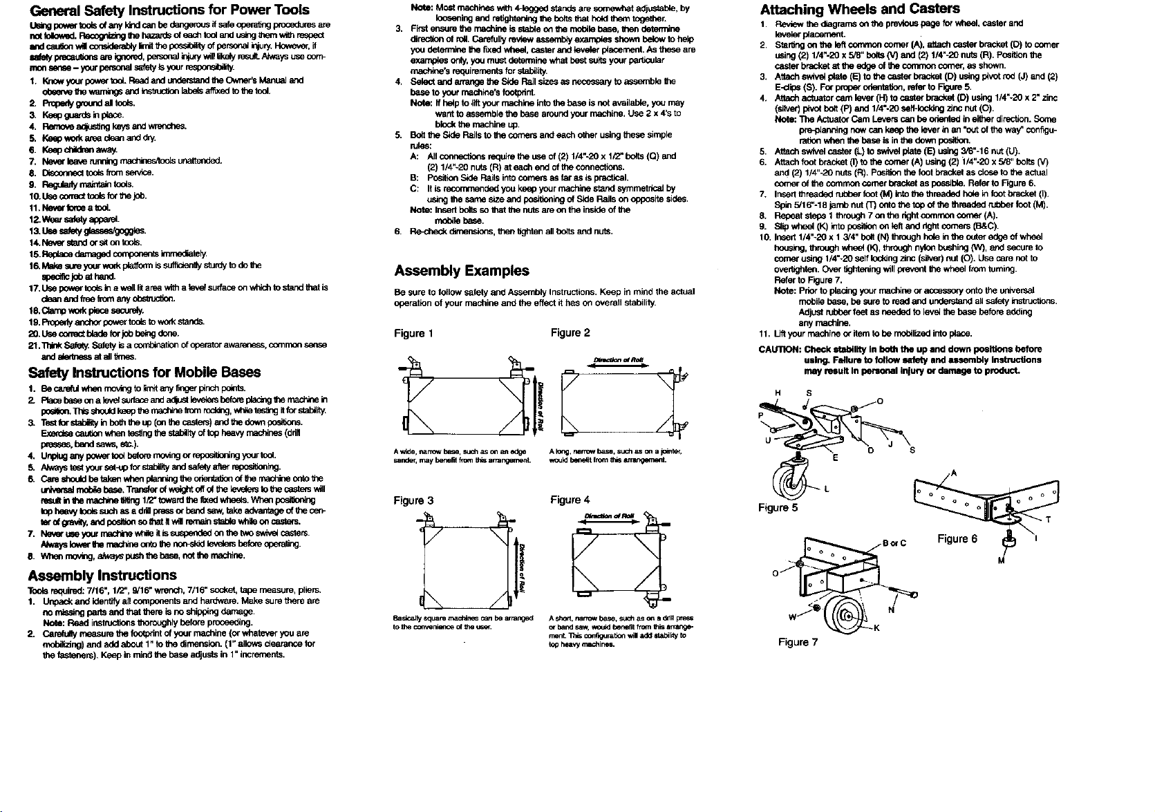
Attaching Wheels and Casters
1. Review the diagrams o_ thep_ pageforwheel, caste_and
ieve_ placement.
2. Star_g on tbe left convnon comer (A), attach caster bracket(D) tocomer
using(2) 1/4"-20 x5/8" bo6s {V) and (2) 114"-20nuts(R). Positionthe
caster bracketat tbe edge of tbe common comer, as shown.
3, Attochsw_v_ p4_te(E) to thecaste_bracket (D) usingpivotrod(J) and (2)
E-clips (S). Fo_properobeofation,refer to F_jure5.
4. Attochack_tor cam lever(H) to casto_brack_ (D) using 1/4"-20 x 2"zinc
(silver) pivotbblt(P) and 1/4"-20 se/f-lodd_j zinc nut(O).
NOto: "l_heActuatorCam Leverscan be odentedin eitherdirection.Sonm
pre-plenblngnow can keep tbe leverin an '_ut of the way_configu-
ra6onwhen tbe bese is in the downposi0on.
5. Attachswivel caster (L) to swivel prate(E) using3_8"-16nut(U).
6. Attachfootbrachet(I)tothe¢omer(A)u_ng(2)l/4"-2Ox518"bolbl(V)
and (2) 114"-20nuts (R). Positionthe foot bracketas closeto the actual
comerof tbe comrnoncomer brad<et as pos=bio. Refer to Rgure 6.
7. InsertI_readnd mt:t_r foot(M) iofothethreaded hole infoot brackel(I).
Sple 5/16"-18 jamb nut (T) onto the top of the threaded rL_ber foot (M).
8. Repeat steps 1 through7 o_ f_e dght commoncomer (A).
g. S6p wheel (K) into po_i_ onleft and dght comers (B&C).
10. Insert1/4"-20 x t 3/4" bolt (N) through holeinthe outeredge of wheel
housk_, throughwhee_(K), _ nylo_bushing(W), and secure to
comerusing I/4"-20 self ioddng zinc (silver)nut (O). Use care not to
over_ghten.Ove_ itghte_ing w_llpreventthe wheel Imm toming.
Refer toRgure 7.
Note: Priorto plating your machine or acces,soryontothe ur_vemal
mobile b_se, be sure to read and understandall sofelyinstructions.
Adjust _ feet as needed to iove_thebese before adding
any machine.
11. Liftyour machineor itemto be mobilized intop_ace.
CALI13CN:Check stability In bout the up and down po_itions before
Figure 5
using. Failure to follow safety and assembly Instructions
may mult In personal InJuq/o_rdamage to product.
H S
8orC
w _ I
Figure
 Loading...