

Craftsman 20930 Owner's Manual
Operator’s Manual
VACUUM PUMP/BRAKE BLEED KIT
Model 20930
CAUTION: Before using this
product, read this manual and
follow all its Safety Rules
and Operating Instructions.
• Safety
• Operation
• Specifications
• Vacuum Systems
• Diagnostics
• Parts and Accessories
• Español, p. 20
Sears, Roebuck and Co., Hoffman Estates, IL 60179, U.S.A.
www.craftsman.com

CONTENTS
Service Parts& Accessories . . . . . . . . . . . . . . . . . . . . . . . . . . . . . . . . . . . . . . . . . . . . . . . . . . . . . . . . . . . 1
The Pump . . . . . . . . . . . . . . . . . . . . . . . . . . . . . . . . . . . . . . . . . . . . . . . . . . . . . . . . . . . . . . . . . . . . . . . . 2
The Automotive Vacuum System . . . . . . . . . . . . . . . . . . . . . . . . . . . . . . . . . . . . . . . . . . . . . . . . . . . . . . . 4
Diagnosing Mechanical Engine Conditions.. . . . . . . . . . . . . . . . . . . . . . . . . . . . . . . . . . . . . . . . . . . . . . . . 6
Positive Crankcase Ventilation System .. .. .. .. .. .. .. .. .. .. .. .. .. .. .. .. . . . . . . . . . . . . . . . . . . . 8
Exhaust Gas Recirculation (EGR) . . . . . . . . . . . . . . . . . . . . . . . . . . . . . . . . . . . . . . . . . . . . . . . . . . . . . . . 9
Spark Delay Valves (SDV) . .. .. .. .. .. .. . . . . . . . . . . . . . . . . . . . . . . . . . . . . . . . . . . . . . . . . . . . . . . 13
Electrical/Vacuum Solenoid . . . . . . . . . . . . . . . . . . . . . . . . . . . . . . . . . . . . . . . . . . . . . . . . . . . . . . . . . . 14
Thermal-Controlled Vacuum Switching Valves .. .. .. .. .. .. .. . . . . . . . . . . . . . . . . . . . . . . . . . . . . . . . 14
Brake Bleeding . . . . . . . . . . . . . . . . . . . . . . . . . . . . . . . . . . . . . . . . . . . . . . . . . . . . . . . . . . . . . . . . . . . 16
Spanish Section. .. . . . . . . . . . . . . . . . . . . . . . . . . . . . . . . . . . . . . . . . . . . . . . . . . . . . . . . . . . . . . . . . . 20
CRAFTSMAN ONE YEAR FULL WARRANTY
If this Craftsmanproduct fails due to a defect in material or workmanship within one year from the date of
purchase, RETURN IT TO ANY SEARS STORE OR OTHER CRAFTSMAN OUTLET IN THE UNITED STATES FOR FREE
REPLACEMENT.
This warranty applies for only 90 days from the date of purchase if this product is ever used for commercial
or rental purposes.
This warranty does not include vacuum pump seals, which are expendable parts.
This warranty gives you specific legal rights, and you may also have other rights which vary from state to
state.
Sears, Roebuck and Co., Hoffman Estates, IL 60179
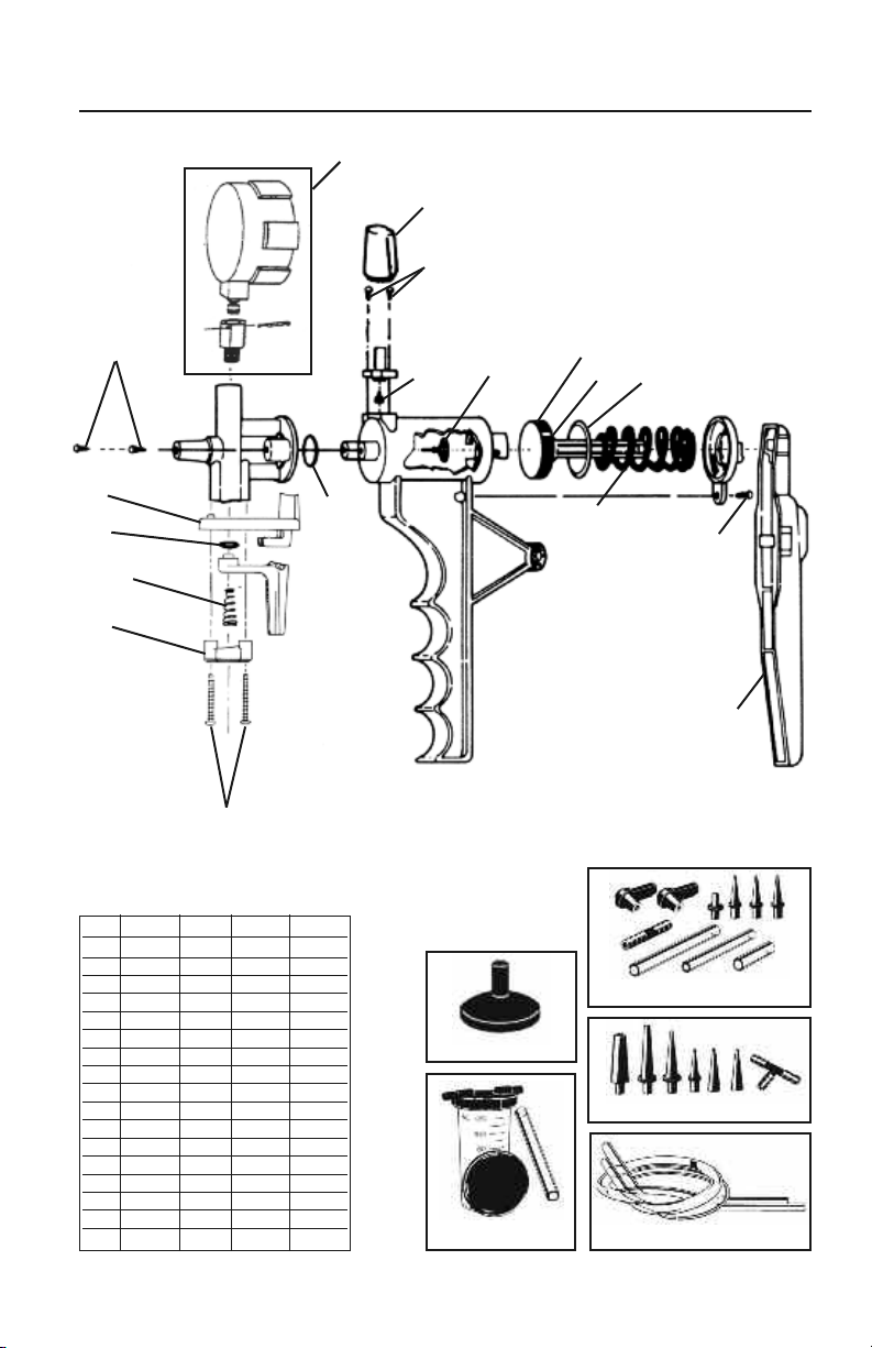
SERVICE PARTS & ACCESSORIES
06172
14
10
11
16
6
7
12
17
13
PUMP SERVICE KITS
This Kit 04100 823371 823311
1X X X
2X X
3X X
4X X
5X X
6X X
7X X X
8X
9X
10 X
11 X
12 XX
13 XX
14 X
15
16 X
17 X
1
2
822392 – Suction Cup
822390 – Reservoir Kit
3
4
5
8
822303 – Adapter Kit
822303 – Adapter Kit
822391 – Tubing (2 pieces)
9
823373
1

THE PUMP
The vacuum pump is an extremely versatile service
tool that can be used to test a variety of automotive
systems and perform a number of useful tasks.
Though the pump has obvious uses for testing
various vacuum motors, control valves and vacuum
sources, its applications don’t end there. Almost
any part or system that requires proper sealing,
pressure or vacuum to operate can be tested with
the vacuum pump. The pump and its accessories
also transfer fluids, help to bleed brakes and aid in
other tasks. The pump also meets diagnostic tool
requirements when such tools are specified for some
state vehicle inspection programs.
This section will describe the pump, give
specifications, tell how to use the pump and
provide some service tipsto helpyou keep your
pump in tip-top shape.
DESCRIPTION
The hand-held vacuum pump is simple, accurate,
easy to use, and has many applications. It consists
of a pump body, moveable handle, vacuum gauge,
vacuum fitting and a safety-capped pressure fitting.
The pump is easily held in your hand, and when the
handle is squeezed, a vacuum is drawn at the
vacuum fitting. If the vacuum fitting of the pump
is connected to a closed container or system, the
gauge will show the vacuum level. If the pressure
fitting is attached to the container or system, a
pressure will be generated but will not show on the
gauge. If it is desired to read the amount of
pressure, a separate pressure gauge is required.
VACUUM RELEASE
The vacuum is released by pulling back on the
Vacuum Release Lever. This action allows air to enter
the system, thus relieving the vacuum. Vacuum will
also be released when the hose is detached from the
vacuum fitting.
SAFETY CAP
The small cap on the pressure fitting is pressed on
with a friction fit. It can be removed with a twisting
pull. The cap is used to prevent any fluids (brake
fluid, gasoline, etc.), which may have accidentally
been pulled into the pump, from squirting into the
user’seyes. Forthis reason, the cap should always
be in place when using the pump, except when
attaching a hose to the pressure fitting. The pump
will last for many years when cared for properly.
See PROPER CARE in this section.
SPECIFICATIONS
Maximum Vacuum Approx. 25" Hg
@ Sea Level: (85 kPa)
Stroke Volume: 1 cu. in. (16cc)
Maximum Pressure
(Unassisted): 15 psi (103 kPa)
(Assisted): 30+ psi (207+ kPa)
Gauge Accuracy 3%-2%-3%
(15-20 in Hg): of full range
USING THE PUMP
The vacuum pump is simple to use. In most cases,
the pump is either attached directly to a component,
used in place of a vacuum line or connected into a
vacuum circuit with a tee connector. The pump can
be operated as a test instrument in three ways:
1) When vacuum is desired for a test, the movable
handle of the pump is simply squeezed with your
hand, as in clenching your fist. Continue strokes
until desired vacuum is indicated on the gauge.
2) The pump can be connected into a vacuum circuit
and used to measure existing amounts of vacuum,
just as any vacuum gauge would be used. When
used this way, donot pump the handle, or incorrect
readings may result.
2

THE PUMP
3) The pump can also be used as a pressure pump
by removing the safety cap and connecting to the
pressure fitting. When the pump handle is released
from the closed position, pressure is created.
Additional pressure can be applied by manually
pushing in the piston pump rod.
CAUTION: Always be sure the safety cap is in place
unless the pressure fitting is being used. Other
sections of this manual outline specific uses for
the pump.
PROPER CARE
Yourpump isa sturdilybuilt, precision test
instrument. Do handle it carefully!
Don’t drop or handle roughly as the gauge accuracy
may be affected. Care for your pump and it will
give you years of trouble-free service.
LUBRICATION
The factory-installed lubricantis silicone oil and
should provide very longservice. If you find it
necessary to lubricate yourpump, usesilicone oil.
If unavailable, you may use DOT 5 (not DOT 3)
silicone-based brake fluid or a salad vegetable oil.
Do not use petroleum based fluids or spray
lubricants (WD-40, motor oil, etc.), as these will
damage the pump.
3
THE AUTOMOTIVE VACUUM SYSTEM
This manual deals with vacuum, how it is used in
various automotive systems and how the vacuum
pump can be used to test and diagnose these
systems. This section discusses what vacuum is,
how it is measured, where it comes from on an
automobile, the system for distributing and using
vacuum, and some troubleshooting basics.
WHAT IS VACUUM?
Put simply, vacuum is empty space, and may exist
as either a total or partial vacuum. Vacuum does
not, of itself, create power. Rather, power for
vacuum devices depends on the presence of
atmospheric pressure. The atmosphere exerts a
pressure of 14.7 pounds per square inch (psi) on
everything atsea level.If aportion of the air is
removed from one side of a diaphragm (partial
vacuum), the atmospheric pressure will exert a
force on the diaphragm. The force is equal to the
pressure difference times the diaphragm area
(FIGURE 1). Generally, the less air (greater vacuum)
in a given space, the more the atmosphere tries to
get in and the more force is created.
HOW IS VACUUM MEASURED?
In the United States, vacuum is commonly measured
in inches of Mercury ("Hg). Itmay alsobe
measured in centimeters of Mercury (cm Hg) and
kiloPascals (kPa). Atmospheric pressure will support
a column of Mercury ina manometergauge about
30 inches high or about 76 cm high. This is the
barometric pressure in " Hg which varies as the
weather changes. Vacuum readings in " Hg are
really negative pressure readings. For example,
30" Hg vacuum would be a complete vacuum. Half
of a complete vacuum would be 15" Hg. A gasoline
engine at idle usually pulls about 16-22" Hg
vacuum. On deceleration, because the throttle is
closed, the vacuum will increase. The pump will pull
about 25" Hg as indicated on its vacuum gauge
which is calibrated in both " Hg and kPa.
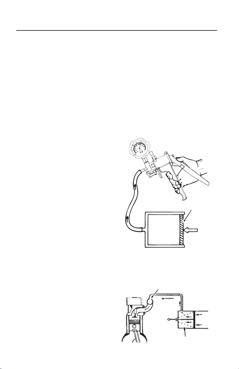
WHY ENGINES CREATE VACUUM
Vacuum is created when air is withdrawn from
a given volume, or a sealed volume is increased.
That is why vacuum is available in an engine.
On the intake stroke, the piston moves down, this
creates a partial vacuum because the volume of the
cylinder is increased. Air cannot rush through the
intake system fast enough to totally fill the space
created when the piston moves down (FIGURE 2).
This is the most common automotive vacuum
supply source.
GASOLINE VS. DIESEL VACUUM
Because a diesel engine does not produce as much
vacuum as a gasoline engine, a mechanical vacuum
pump must be employed to operate vacuum
devices. The pump is useful in testing devices
on both types of engines.
Piston area 10 sq.in.
14.7 PSI
10.7 PSI
40 Pounds
14.7 - 10.7 =4 PSI
FIGURE 1:
VACUUM VS. ATMOSPHERIC PRESSURE
Intake Stroke
FIGURE 2: THE ENGINE AS A VACUUM SOURCE
4
Vacuum Port
Air
Vacuum
THE AUTOMOTIVE VACUUM SYSTEM
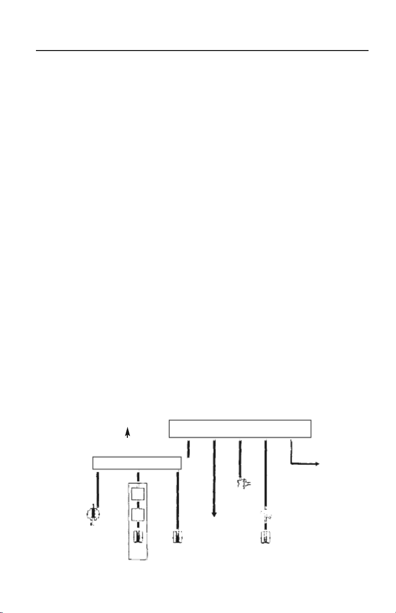
VACUUM DISTRIBUTION
All modern automobiles have a vacuum distribution
system (FIGURE 3), consisting of lines, hoses,
fittings and vacuum devices. This system must be
leak proof. If it is not, the engine air/fuel mixture
will be leaned out by the extra air entering the
system through the leaks, thus causing problems
such as burned exhaust valves, uneven idle, stalling,
pre-ignition, burned spark plugs, etc. Additionally,
any vacuum operated device affected by the
vacuum leak will not function properly.
A normal gasoline engine should develop 16-22" Hg
of intake manifold vacuum at idle. This is an
indication that the engine is breathing properly.
If the vacuum is lower, the engine is running less
efficiently.The lower the manifold vacuum, the less
efficiently the engine is running and the lower the
gas mileage will be.
The vacuum distribution system supplies vacuum
to vacuum motors (servos) inthe airconditioning,
power brake booster, speed control servo, emission
controls, manifold absolute pressure (MAP) sensor,
and automatic transmission control systems. In older
vehicles, vacuum is also supplied to the distributor
vacuum advance or retard mechanism. These
devices can be connected directly to manifold
vacuum, or can be controlled through electric
solenoids, thermostatic switches, or other
vacuum controls.
TROUBLESHOOTING THE VACUUM SYSTEM
Most vacuum problems can be traced to leaks, which
occur in hoses, connectors, motor diaphragms or
valves. Pinched lines or clogged valves will also not
allow vacuum flow. Problems can also be traced to
improper mechanical operation of devices driven by
vacuum motors.
The vacuum pump can be used to measure the
amount of vacuum in a hose. The vacuum gauge
feature is very usefulfor detecting afluctuating
vacuum supply or a leaky hose. The vacuum pump
feature enables you to check all types of vacuum
operated devices.
On a vacuum motor, for example, the pump is used
to evacuate the diaphragm chamber, which allows
you to check the mechanical operation of the device
as well as the amount of vacuum required to
actuate it. Testfor aleaking diaphragmby applying
10" Hg vacuum to the device (FIGURE 4). Observe
the gauge to see if the needle drops after the
actuator stops moving. If the needle continues
to drop, a leaking diaphragm is indicated. If the
diaphragm is okay, thevacuum should hold for
one minute with the needle steady.
VACUUM DISTRIBUTION BLOCK
To Intake Manifold
Power Brake
Booster
Distributor
Intake Air Motor
FIGURE 3: TYPICAL VACUUM DISTRIBUTION SYSTEM
Advance
To Speed
Control
5
To A/C
Heater
Auto
Trans
PRNDL Switch
Brake
Release Motor
THE AUTOMOTIVE VACUUM SYSTEM
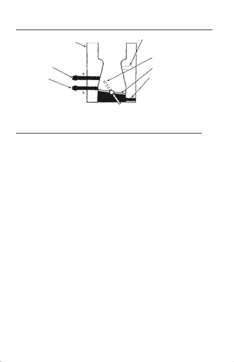
Carburetor or Throttle Body
EGR Vacuum
• Zero at closedthrottle
• Still zero when “S”vacuum ison
• Equal to manifoldat greater
throttle opening
Spark Port Vacuum
• No vacuum at
closed throttle
• Equal to manifoldvacuum off idle
• Originally used to control“spark” vacuum
to distributor advance diaphragm
FIGURE 4: TYPICAL CARBURETOR VACUUM SUPPLY POINTS
Venturi Vacuum
• Weak or zero atcruise or idle
• Strong at wideopen throttle
Position when “S” and “E”
vacuum are “on”
Throttle plate (closed position)
Manifold Vacuum
• Available with engine running
• Strongest at closedthrottle
• Gradually weakens as throttleopens
• But stays strongif the chokeis closed
DIAGNOSING MECHANICAL ENGINE CONDITIONS
VACUUM GAUGE CHECKS & DIAGNOSIS
The pump’s vacuumgauge readingsgive indications
of possible mechanical problems, but they are not
foolproof. Observe thegauge carefully andfollow
the vacuum readings with further tests, where
possible, to confirm your diagnosis.
Do not look for the engine to produce specific
(numerical) amounts of vacuum. Much more
important than specific numbers, are the range
of the vacuum readings and the movement of the
needle (FIGURE 5). Important things to notice about
the needle movement are HOW the needle moves
(in a smooth or jerky manner, erratic, etc.), what
direction it moves, whether movement is regular or
varying, and how far the needlemoves.
The following gives some examples of what to
look for and the meanings of a variety of vacuum
gauge readings.
NORMAL ENGINE
Run engine at idle and connect the pump to an
intake manifold vacuum port. Watch the needle’s
movement on the gauge. At idle, the vacuum gauge
reading should be 16-22" Hg and steady.
BURNED OR LEAKING VALVE
At idle, burned or leaking valves will cause the
pointer on the gauge to drop to a low reading and
return to normal at a regular interval. The needle
will drop from 1 to 7" Hg at regular intervals
whenever the defective valve attempts to close.
STICKING VALVE
A sticking valve will exhibit a rapid, intermittent
drop from the normal pointer indication. This is
unlike the regular drop that characterizes a
burned or leaking valve.
A sticking valve condition may be pin-pointed by
directly applying lightweight oil to each valve guide.
When the sticking valve is reached, the situation will
be temporarily remedied.
WEAK OR BROKEN VALVE SPRING
Weak valve springs are indicated when the pointer
of the vacuum pump gauge fluctuates rapidly
between 10" and 21" Hg at idle. The fluctuations
will increase with engine speed. A broken valve
spring will cause the needle to fluctuate rapidly
at a regular interval. Again,this will occurevery
time the valve attempts to close.
WORN VALVE GUIDES
Worn valve guides admit air which upsets the
air/fuel mixture. The vacuum gauge reading will
be lower than normal and will fluctuate rapidly
in a range of about 3" Hg. As the speed of the
engine is increased, the needle will steady.
6
DIAGNOSING MECHANICAL ENGINE CONDITIONS
LEAKING PISTON RING
Vacuum at idle will be low but steady at about 12 to
16" Hg. Open the throttle and allow the engine to
pick up speed to about 2000 RPM, and then close
the throttle quickly.The pointer should jump 2 to 5"
Hg above its low steady reading. A lesser gain may
indicate faulty rings, and a complete cylinder
leakage or compression test should be done.
BLOWN CYLINDER HEAD GASKET
At idle, the vacuum pump gauge pointer will
fluctuate between normal and a low reading.
The needle will drop sharply about 10" Hg from
a normal reading and return each time the defective
cylinder or cylinders reach firing position.
EXHAUST RESTRICTION TEST
An exhaust restriction will cause normal or nearnormal performance at engine idle, butcause very poor
engine performance under load or at higher speeds.
1) Connect the pump hose to an intake manifold
vacuum fitting. Operate the engine at idle and
note the vacuum reading and needle movement.
Compare readings and movements against
descriptions listed for burned valves and late
ignition or valve timing.
2) Watch the vacuum gauge as engine speed is
increased to approximately 2500 RPM.
3) An increasein vacuum over that obtained at idle
indicates an exhaustsystemthat is free of restrictions.
4) If the needle drops toward zero as engine RPM
is increased, either an exhaust restriction or an
over-active Exhaust Gas Recirculation (EGR) valve
is causing the problem.
5) Test theEGR valveseparately. If itis foundto
be in good condition, the problem is a restricted
exhaust. Check and replace if necessary.
INCORRECT IDLE AIR/FUEL MIXTURE
If the gauge needle drifts slowly back and forth at
idle,over a range of 4to 5" Hg,the fuel mixture is
too rich. A lean mixturewill cause an irregular drop
of the needle over about the same range.
INTAKE MANIFOLD OR AIR INDUCTION
LEAKS
If there are any air leaks in the air induction
system, the gauge needle will be about 3 to 9" Hg
below normal, but will remain steady.
LATE IGNITION OR VALVE TIMING
An extremely low but steady reading at idle
indicates late ignition or valve timing, or a
uniformly close setting of the valve lash.
Perform separate tests to determine which
of these problems, if any, have affected
the engine.
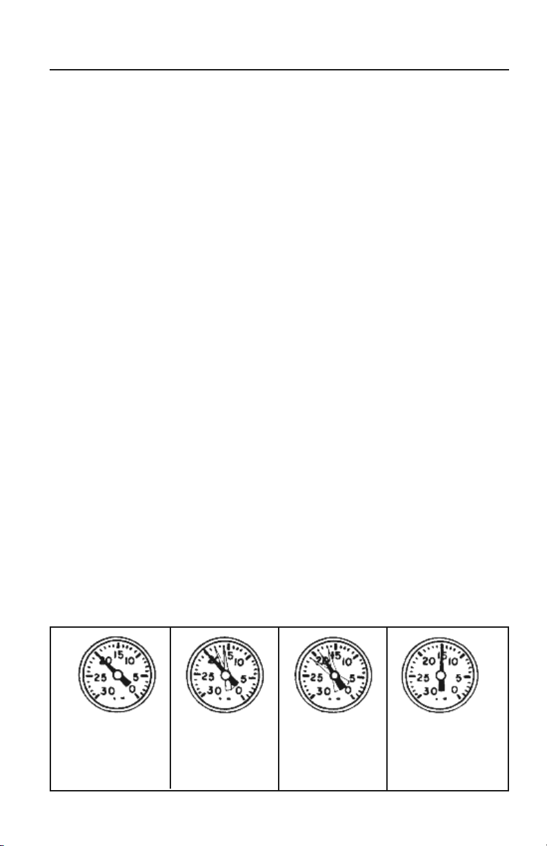
With motor at idle speed,
vacuum pointer should hold
steady between 16 and 22.
FIGURE 5: VACUUM GAUGE READINGS
With motor at idle speed,
dropping back of vacuum
pointer indicates sticky
valves.
With motor at idle speed,
floating motion right and
left of vacuum pointer
indicates carburetor too rich
or too lean.
7
With motor at idle speed,low
reading of vacuum pointer
indicates late ignition timing
or intake manifold air leak.

POSITIVE CRANKCASE VENTILATION SYSTEM
SYSTEM OPERATION
The Positive Crankcase Ventilation (PCV) system is
used on all modern engines to reduce air pollution
by providing a more complete scavenging of
crankcase vapors. Air is drawn through a filter
located in the air cleaner, through a hose in the
valve cover, into the crankcase, across and up into
the rear of the intake manifold or opposite valve
cover, through the PCV valve, through a hose, into
the intake manifold. Intake manifold vacuum draws
in all vapors from the crankcase to be burned in
the engine
When air flow through the carburetor or throttle
body is high, added air from the PCV system has
no effect on engine operation. However, at idle, air
flow through the carburetor or throttle body is so
low that any large amount added by the ventilation
system would upset the air/fuel mixture, causing a
rough idle. For this reason, the PCV valve restricts
the ventilation system flow when intake manifold
vacuum is high.
SERVICE PROCEDURES
After a period of operation, the PCV valve may
become clogged and reduce the amount of
crankcase ventilation. The PCV valve should be
replaced periodically to prevent the formation of
acids in the crankcase, and the build up of excessive
crankcase pressure, which could force engine oil out
past the seals. Use the following procedure to check
the PCV system using your pump:
3) Clamp off the vacuum hose to the PCV valve.
The engine speed should decrease 100 RPM to
indicate the loss of the calibrated air leak into
the intake manifold. The vacuum gauge reading
should increase slightly, indicating that the vacuum
leak has been plugged. If this does not happen,
replace the PCV valve and/or replace any damaged,
plugged or loose hoses.
4) If the engine is idling too slow or is rough, this
may be caused by a clogged PCV valve or hose.
Do not adjust the idle speed without first checking
the PCV system.
5) After installing a new PCV valve, always adjust
the idle speed, and if possible, the idle air mixture.
The installation of the wrong valve may cause too
much vapor to flow through the system if the
calibrated bleed is too large. This will lean out the
air/fuel mixture excessively. If the opening is too
small, the plugging effect will be nullified, emissions
will increase, acids will form and oil leaks may
develop. Be sure you get the correct PCV valve
for your car.
1) Inspect the system for kinked, plugged or
deteriorated hoses. Check to be sure all hoses
are connected properly.Repair as necessary.
2) Connect your pump to an intake manifold port
and check the vacuum reading of the warmed and
idling engine.
8
EXHAUST GAS RECIRCULATION (EGR)
An Exhaust Gas Recirculation (EGR) system is used
on most modern engines to reduce Oxides of
Nitrogen (NOx) emissions. During the combustion
process, nitrogen, which makes up 80 percent of
the air, will mix with oxygen at temperatures
above 2,500°F. During thecombustion process,
temperatures in the cylinders go well above
3,500°F providing the ideal conditions for the
formation of NOx.
SYSTEM OPERATION
To reduce theformation ofNOx, itis necessary to
lower the combustion temperature. This is most
often done by introducing exhaust gases back into
the combustion chamber through the use of an
EGR valve. The EGR valve (FIGURE 6) may be
operated by ported vacuum from above the
throttle plates, or by a sophisticated control
system that modulates the amount of EGR
depending on the temperature of the coolant,
ambient air temperature, engine speed or load.
An EGR valve that does not have a sophisticated
control system must be fully closed with a vacuum
of less than 2" Hg and begin to open with 2 to 8.5"
Hg of vacuum. At idle and wide-open throttle, the
ported vacuum supply is low and the valve should
be closed.
Some cars have a Back-Pressure Transducer Valve
(BPV) to modulate the operation of the EGR system.
Some cars have a Venturi Vacuum Amplifier(VVA)
to do the same job. The effect is to modulate the
amount of EGR according to the load on the engine.
To improve colddrivability,most cars are equipped
with some type of vacuum control device to shut off
EGR while the engine is cold.
EGR systems fail in two ways. Either the valve may
fail due to a fault of its own, such as a ruptured
diaphragm, or due to a loss of control vacuum.
Always check whether there is vacuum at the hose
connected to the EGR valve, before replacing the
valve. Connect the pump to the vacuum supply hose
at the EGR valve and check whether at 2000 RPM
there is at least 4 to 5" Hg vacuum available.
Remember also that clogged exhaust passages that
lead to or from the valve can restrict the flow even
if the valve is opening.
An EGR valve that remains open will cause the
engine to idle roughly, die at idle, and lose power
and full-throttle smoothness. Dirt or damage in the
valve seat area usually cause the valve to fail. An
EGR valve can operate normally with the engine
warm but remain open when the engine is cold.
That condition could be caused by a faulty thermal
switching device that does not cut off the vacuum
supply when the engine is cold.
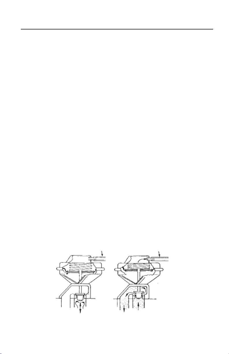
To Vacuum Source
No Vacuum Signal
Valve closed, exhaust blocked
FIGURE 6: EGR VALVE OPERATION
To Vacuum Source
Vacuum Signal Applied
Valve open, exhaust admitted tointake manifold
9
EXHAUST GAS RECIRCULATION (EGR)
EGR SERVICE PROCEDURES/GENERAL TEST
EXCEPT GM OR BACKPRESSURE
CONTROLLED TYPE
If the symptoms of an engine lead you to believe
that an EGR valve is staying open, follow this
procedure:
1) Connect a tachometer to the engine and run
the engine at idle speed until it reaches normal
operating temperature. Use the pump to check for
at least 10" Hg vacuum at the valve. Replace the
hose and note the engine RPM.
2) Remove the vacuum hose from the valve and
notice whether engine RPM increases.
3) If engine speed does increase, there may be
some type of problem in the vacuum control
circuit. Check the routing of all vacuum hoses.
4) If engine speed or the quality of idle changes,
remove the valve and check the pintle and valve
seat to make sure both are clean. If they are not,
replace the valve, gasket and adapter if it is burned,
warped or damaged.
If the engine symptoms lead you to believe that
the EGR valve is staying closed, follow the
procedure below:
1) Operate the engine at idle until it reaches full
operating temperature. Use the pump to check for
the presence of 10" Hg vacuum at the valve. Set the
engine speed at approximately 2000 RPM. Plug the
vacuum supply hose. Connect the vacuum pump to
the EGR valve and apply 10 to 15" Hg vacuum.
2) The diaphragm should move to the open position
and a decrease in engine RPM should be noted. If
not, the valve is defective or the manifold passages
are plugged. Release the vacuum on the EGR valve.
3) The diaphragm should move to the closed
position and an increase in engine RPM should be
noted. Return the engine to idle and turn it off.
4) Connect the pump to the EGR valve and test by
applying at least 9" Hg of vacuum to the diaphragm
and watch the gauge carefully for any vacuum loss.
5) If the valve diaphragm does not move, or cannot
hold vacuum, replace the EGR valve.
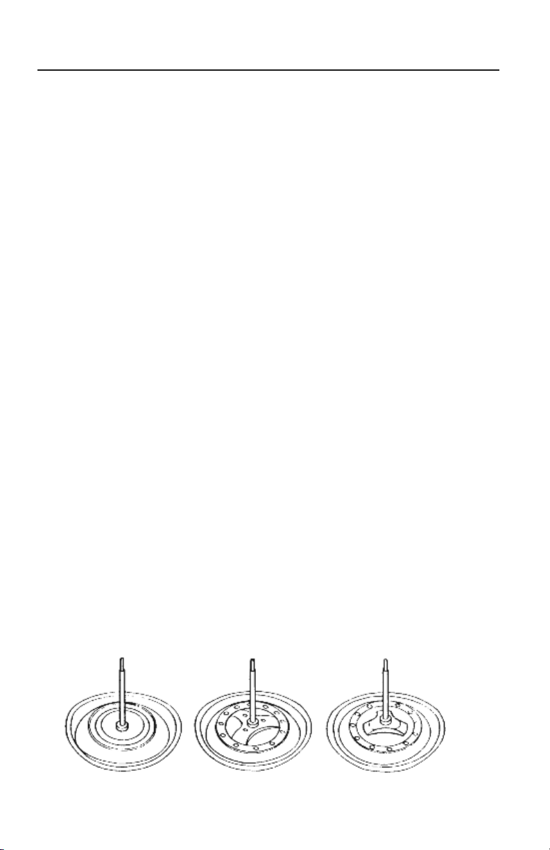
GM EGR VALVES
General Motors produces three types of EGR valves.
Each valve can be identified by the design of its
diaphragm plate (FIGURE 7). The first valve is a
ported vacuum EGR that has only a circular rib on
the back of its diaphragm plate. The second is a
positive backpressure valve with X-shaped ribs that
are raised only slightly above the plate. Finally,
there is a negative back-pressure valve with
X-shaped ribs raised well above the diaphragm
plate. Both the ported vacuum and negative
back-pressure valves are tested the same way.
A separate test is listed to check the positive
back-pressure valve.
GM PORTED VACUUM AND NEGATIVE
BACK-PRESSURE EGR TEST
1) Make sure all vacuum hoses are routed
according to the emission control label.
Ported Vacuum Positive Backpressure Negative Backpressure
FIGURE 7: GM EGR DIAPHRAGMS
10
EXHAUST GAS RECIRCULATION (EGR)
2) Check the vacuum connection to the EGR valve
for obstructions.
3) Connect the pump between the EGR valve and
the carburetor or vacuum source. Start the engine
and run it at idle until it reaches operating
temperature (195°F approx.). Check for vacuum
at 3000 RPM; it should be 5" Hg minimum.
4) If no vacuum is available in step 3, check for it
between the EGR thermal vacuum switch (TVS) and
the carburetor. If the vacuum is available there,
replace the TVS.
5) If the vacuum supply between the EGR and the
carburetor is adequate, connect the pump to the
EGR valve inlet. Depress the valve diaphragm and
apply approximately 10" Hg vacuum to the EGR.
To Starter Relay
To Ignition
Vacuum Amplifier
Release the diaphragm and record the time it takes
for the diaphragm to return to its seated position.
6) If it takes less than 20 seconds for the valve to
seat, replace the valve.
GM POSITIVE BACKPRESSURE EGR TEST
1) Follow steps 1 through 4 of the ported vacuum
and negative back-pressure EGR test.
2) Remove the EGR valve from the engine.
Connect the pump to the EGR vacuum inlet and
apply 10" Hg of vacuum. The valve should not
open. If it does, replace the valve.
3) Continue the test by keeping the vacuum applied
and shooting a low-pressure stream of air into the
valve’sexhaust inlet.The valve should now open.
If it does not, replace the valve.
Manifold Vacuum
EGR Delay
Solenoid
EGR Delay
Timer
EGR Valve
CCEGR Temperature Valve
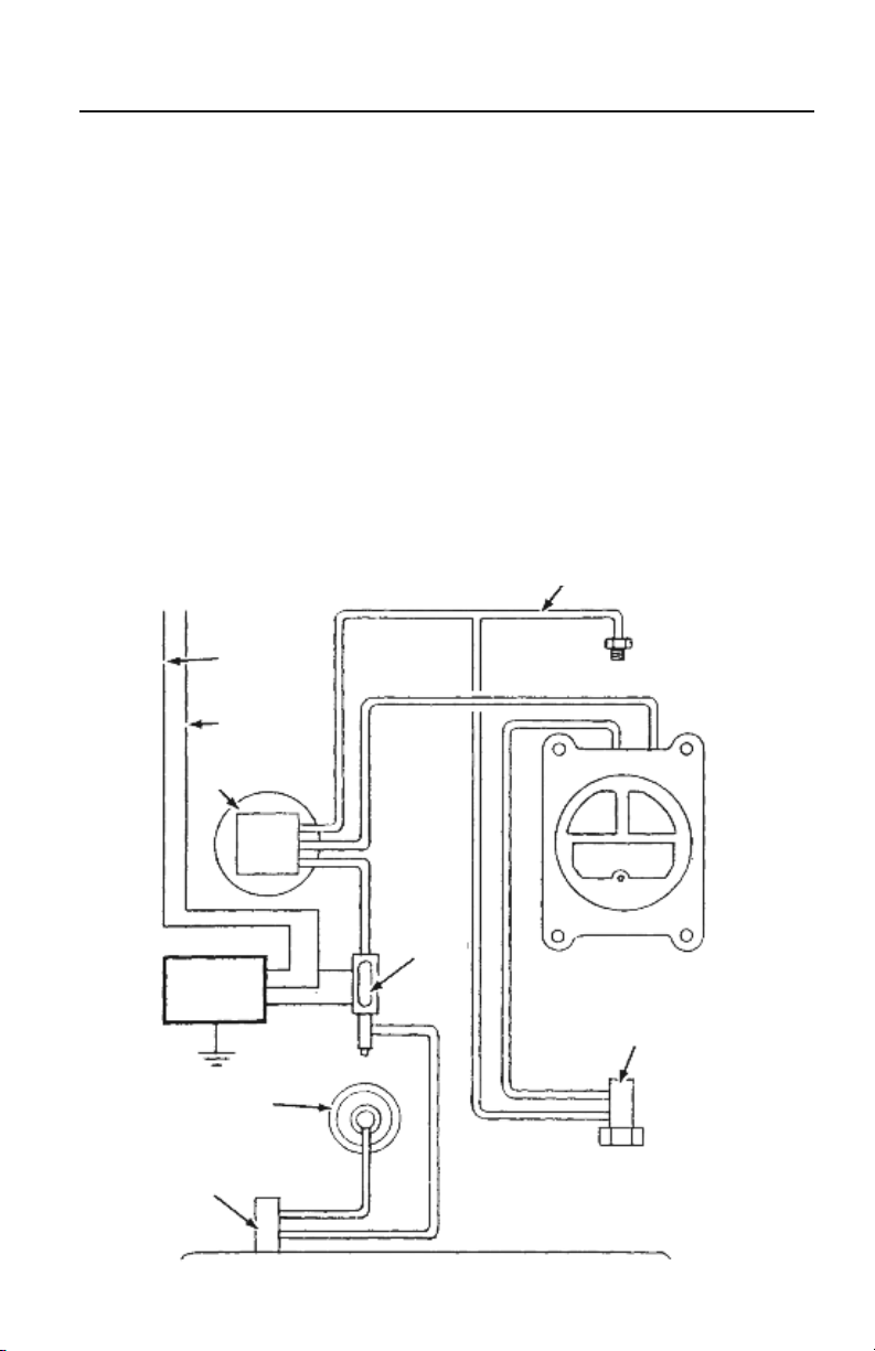
FIGURE 8: CHRYSLER VENTURI VACUUM-CONTROL EGR SYSTEM
11
Coolant Control Engine Vacuum Switch

EXHAUST GAS RECIRCULATION (EGR)
EGR VENTURI VACUUM AMPLIFIER
Some engines utilize a Venturi Vacuum Amplifier
that uses the weak vacuum signal from the throat of
the carburetor to allow the passage of the stronger
intake manifold vacuum to operate the EGR valve.
On most applications the amplifier provides a 2" Hg
boost to the Venturi signal (FIGURE 8).
SERVICE PROCEDURES
1) Start the engine, and run it at idle until it reaches
normal operating temperature.
2) Make sure the intake manifold hose to the
amplifier is properly connected. On those systems
with a reservoir,remove the hose from the reservoir
and use a tee connector to join the hose to the
intake manifold vacuum hose.
3) With separate lengths of hose and different
connectors, bypass any and all vacuum valves or
coolant controlled valves between the amplifier
and the EGR valve.
4) Use a tee connectorto attach the pumpintothe
vacuum line between the amplifier and EGR valve.
5) Increase engine speed to 1500 to 2000 RPM
and release the throttle. Let the engine return to
idle speed and remove the vacuum hose at the
carburetor venturi. The vacuum reading should be
within ± 0.3" Hg of the specified boost for that
amplifier if other than zero boost is specified.
Zero boost may read from 0 to .5" Hg. Replace
amplifier if it is out of specification.
6) Increase engine speed. Watching the vacuum
gauge, release the accelerator after a speed of
1500 to 2000 RPM is reached. If the vacuum gauge
reading shows an increase greater than 1" Hg
during acceleration period, the amplifier should
be replaced.
7) Remove the pump from the output vacuum line
and reconnect the hoses, but still bypass other
valves. Connect the pump and apply 2 to 4" Hg of
vacuum to port on the amplifier which is normally
connected to intake manifold vacuum. The EGR
valve should operate and engine idle should drop or
become erratic. If the EGR valve fails to move,
replace the amplifier.
BACK-PRESSURE TRANSDUCER VALVE
(BPV) OPERATION
The Back-pressure Transducer Valve (BPV) controls
the amount of EGR according to the load on the
engine. An exhaust pressure probe extends into
the exhaust crossover passageway to sample the
exhaust gas pressure. During light engine loads,
the pressure in the exhaust passageway is relatively
low, while during wide-open throttleoperation
(WOT), the pressure is highest. This pressure signal
is transmitted to a diaphragm in the BPV and is used
to control the amount of vacuum applied to the EGR
valve (FIGURE 9).
SERVICE PROCEDURES
1) Remove the air cleaner and plug the intake
manifold fitting. Start the engine and bring it to
normal operating temperature. Position the fast-idle
cam follower on the second step of the fast-idle cam
(to obtain about 1500 RPM), and then note engine
speed on a tachometer. Use the pump to check the
source vacuum at an intake manifold port (FIGURE
10). Note this reading.
2) Tee your pumpinto the vacuum passageway to
the BPV andthe reading should be 1 to 2" Hg of vacuum. Replace the BPV if it is not within specifications.
3) Leave the vacuum gauge at this location, remove
the hose to the EGR valve, and plug the hose opening. Read the vacuum pump gauge, which should be
the same as the intake manifold vacuum reading. If
it is not within 2" Hg of the source vacuum, replace
the BPV valve.
To Distributor
Spark–
EGR Thermal
Vacuum Valve
FIGURE 9:
EXHAUST BACKPRESSURE TRANSDUCER VALVE
12
Exposed to Exhaust GasPressure
To EGR
Valve
 Loading...