

Craftsman 20057983 Owner’s Manual

SEOMU06A-1

Table of Contents
Introduction
Symbols and Icons 2
Inventory 3
Preparation / Tools Required 4
Assembly
Rail and Trolley Assembly 5
Installing the Belt 6-7
Important Installation Instructions 8
Mounting Header Bracket 9
Installation
Attaching Rail to Header Bracket and Mounting Door Bracket 10
Mounting Opener to Ceiling 11
Attaching Door Arms 12
Installing Light and Emergency Release Handle 13
Wiring
Wiring Instructions 14
Connecting Photo Eye Safety System 15
Connecting Door Control Console 16
Connecting Power 17
Adjustment
Aligning the Photo Eye Safety System 17
Travel Limit Adjustment– I. UP Limit 18
Travel Limit Adjustment– II. DOWN Limit 19
Auto Force Adjustment 20
Final Adjustment and Testing 21
Operation
Programming 3-Button Remote 22
Programming Keyless Entry Pad 23
Important Safety Instructions 24
Operating the Opener 25
Door Status vs. Activation 26
Backup Battery Installation / Battery and Status Indicator 27
Backup Battery Features / Motion-Sensing Light 28
Maintenance 29
Troubleshooting 29-30
Repair Parts and Service
Rail Assembly Parts / Installation Parts / Accessories 31
Opener Assembly parts 32
Warranty 33
Symbols and Icons
!
WARNING
DO NOT connect power
*See Accessories in Repair Parts section of this manual for purchase information.
2
READ WARNINGS CAREFULLY to prevent SERIOUS INJURY or DEATH caused by
electrocution or mechanical hazard.
Please connect power
Beeps from built-in buzzer of the opener
Installation hardware are
shown in actual size
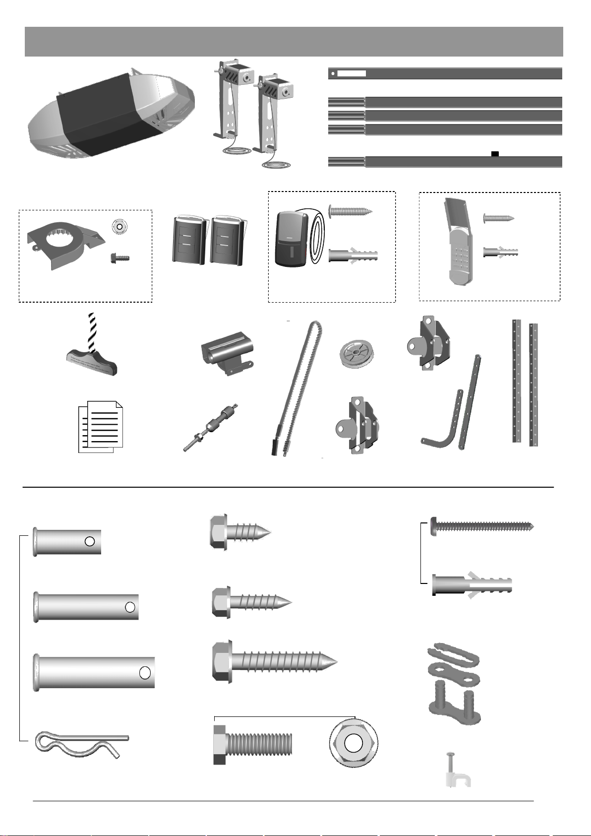
Inventory
Rail — Header Segment
Rail — Middle Segments x3
Opener Unit + Light Lens Cover
x 1
x 1
Sprocket Cover
Emergency Release Handle + Rope
Literature + Safety Labels
Photo Eye Safety System
Two 3-Button
Mini Remotes
Trolley
Trolley Shaft
Rail — End Segment with Trolley Stop Bolt
Screw #6 x 1”
Drywall Anchor
Door Control Console
Pulley
Belt
Door Bracket
Screw #6 x 1”
Drywall Anchor
Wireless Keyless Entry Keypad
Header
Bracket
Hanging
Door Arms
Brackets
x 2
x 2
INSTALLATION HARDWARE, LOCATED IN HARDWARE BAG (SHOWN IN ACTUAL SIZE)
x 2
x 2
Clevis Pin — Door arms
5/16” x 1”
x 1
Self-Threading Screw 1/4” x 5/8”
Door Bracket
x 4
Screw #6 x 1-1/4”
- Push Button
Drywall Anchor
- Push Button
Clevis Pin — Header Bracket
Lag Screw #12 x 1”— Photo Eye System
5/16” x 1-1/2”
x 4
x 1
Lag Screw 5/16” x 1-1/2”
Clevis Pin — Pulley
— Header Bracket / Mounting Opener
3/8” x 1-3/4”
x 5
Hitch Pin — Locking Clevis Pins
Bolt 5/16” x 1”
x 4
5/16” Flange Nut
x 4
— Door arms / Mounting Opener
x 2
x 2
x 1
Master Link Set
—Trolley Shaft
Insulated Staples
— Securing wires
3
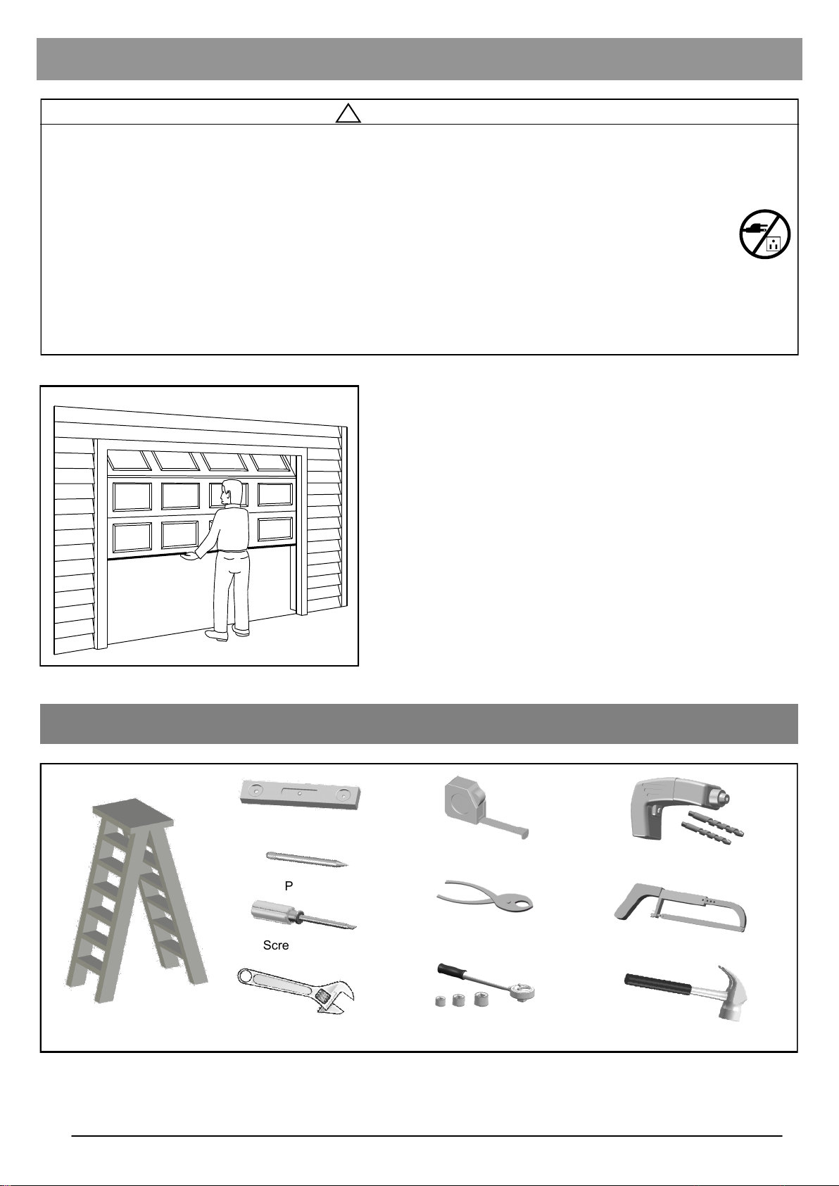
Preparation
!
WARNING
To prevent SERIOUS INJURY or DEATH:
- Before beginning installation of the opener please complete the following test to ensure that your door is
balanced and in good working condition.
- A poorly balanced door can cause serious injury and damage to the opener.
- Always have a qualified garage door service technician make any required adjustments and/or repairs to
your door before proceeding with installation.
- DISABLE ALL LOCKS and REMOVE ALL ROPES connected to the garage door BEFORE installing
and/or operating the opener.
To prevent damage to the door and opener:
- DO NOT connect power until instructed.
- Operate this opener with AC 120V/60Hz power supply ONLY.
DO NOT REUSE PARTS FROM ANOTHER BRAND OF OPENER!!!
Sectional Garage Door
Tools Required
BEFORE beginning Installation:
1. Disable locks and remove all ropes connected to the
garage door.
2. Perform the following door test to ensure your door is
balanced and in good working condition.
To Test Your Garage Door
1. Raise and lower the door to check if there is any sticking or
binding.
2. Check for loose hinges, damaged rollers, frayed cables and
damaged or broken springs.
3. Lift the door approximately halfway and release. The door
should stay at the point under proper spring tension.
Call a qualified garage door service technician if your door binds,
sticks or is unbalanced.
4
Step Ladder
Level
Pencil
Screwdriver
Adjustable Wrench
Tape Measure
Pliers
Ratchet with
5/16”, 7/16” and 1/2” sockets
Drill, 3/16” and 5/16” Drill Bits
Hack Saw
Hammer
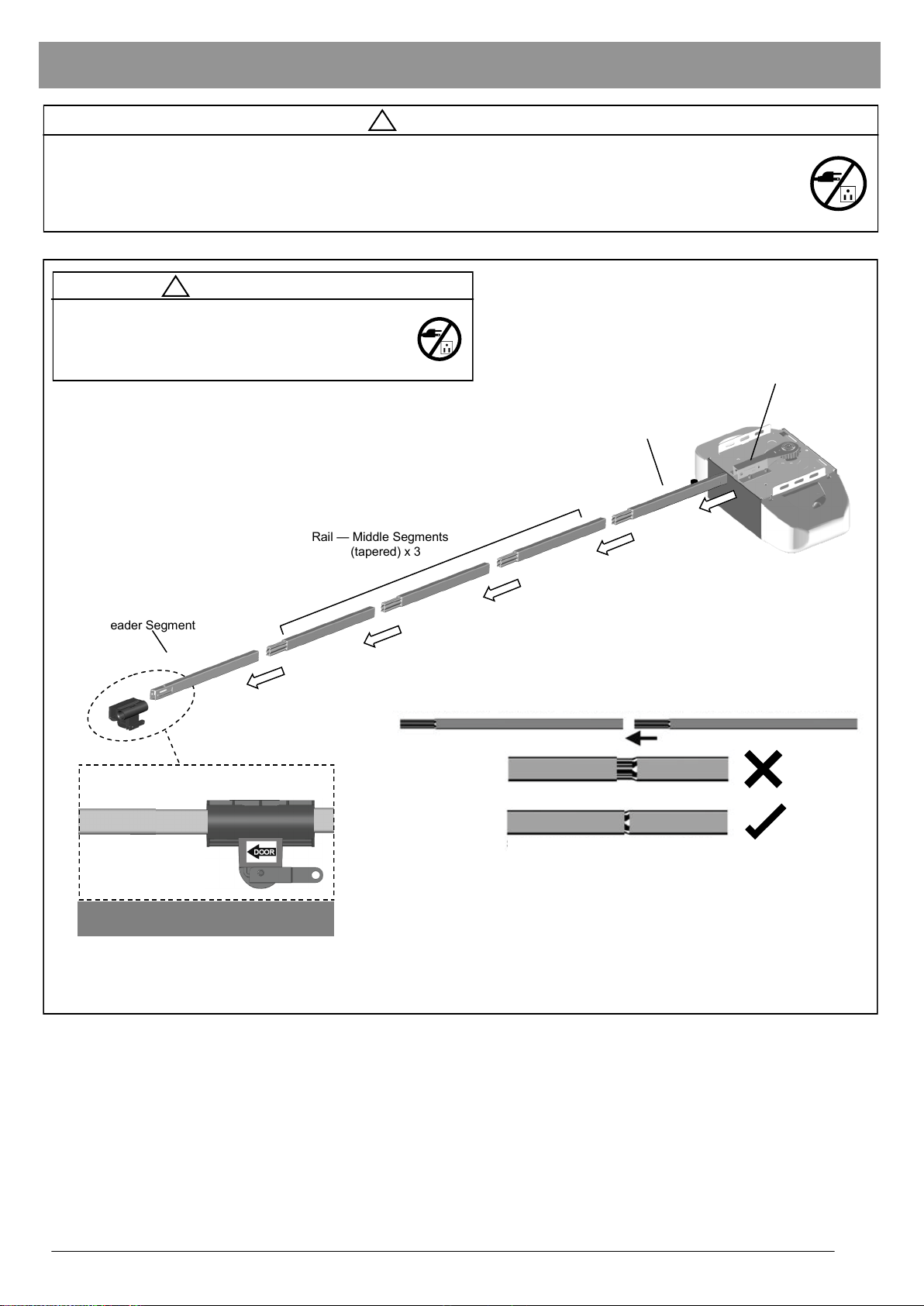
Rail and Trolley Assembly
!
WARNING
To prevent SERIOUS INJURY:
- DO NOT connect power until instructed.
- Keep hands and fingers clear from sprocket during operation.
- Wear gloves when installing belt.
- Keep hands and fingers away from joints and possible sharp edges.
!
CAUTION
- DO NOT connect power until instructed.
- To prevent INJURY, keep hands and fingers
away from joints and possible sharp edges.
- Wear gloves when installing chain/belt and cable.
Rail Bracket
Rail — End Segment (tapered)
with Trolley Stop Bolt
Rail — Header Segment
Trolley direction (Top View)
* VERY IMPORTANT! *
Rail — Middle Segments
(tapered) x 3
Wrong
Loosely connected
Right
Securely connected by applying force
When connecting the rails ensure they are securely connected as shown
above. To apply additional force tap gently on the end of the rail with a
rubber mallet*.
*Only use a soft rubber mallet to tap on the end of the rails as other tools
may damage the rail.
Fig.1
To Assemble Rail and Opener
1. Prepare the rails as shown in Fig.1.
2. Connect the rails starting with the Header Segment. Insert the tapered ends into open ends, apply any additional
force necessary by tapping the Rail on padded flooring. Ensure the End Segment has Trolley Stop Bolt facing up.
Make sure the rails are securely joined together as shown.
3. Slide the Trolley onto the rail from the Header Segment. Make sure the arrow is pointing towards the door as shown .
4. Insert the Rail - End Segment into the Rail Bracket on the Opener. Secure End Segment to Bracket as described on
next page.
5
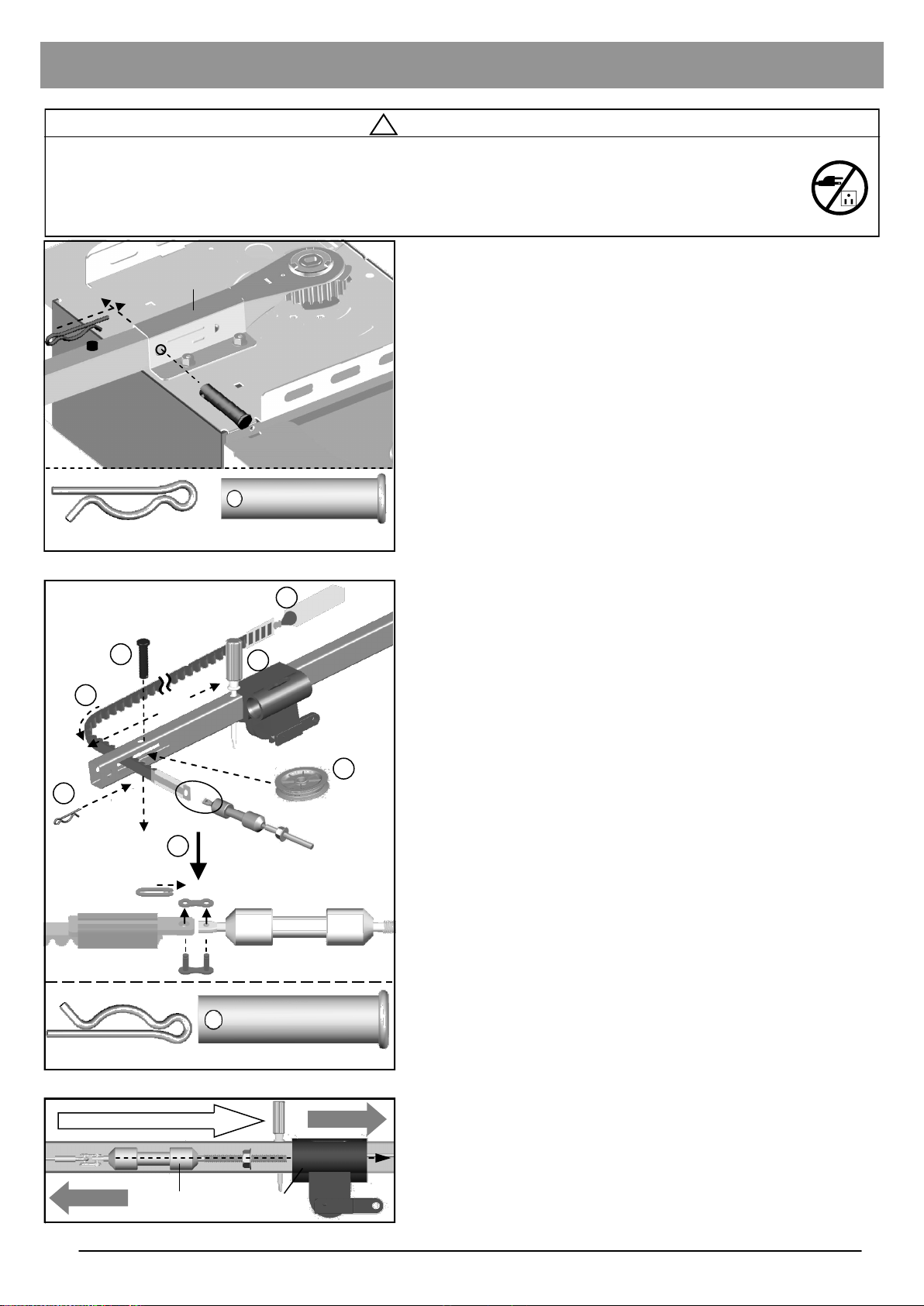
Installing the Belt
!
WARNING
To prevent SERIOUS INJURY:
- DO NOT connect power until instructed.
- Keep hands and fingers clear from sprocket during operation.
- Wear gloves when installing the belt.
- Keep hands and fingers away from joints and possible sharp edges.
To Secure the Rail on the Opener
With the End Segment of the rail fully inserted into the Rail
Bracket, insert a 5/16” x 1-1/2” Clevis Pin through the hole and
lock it into position with a Hitch Pin as shown in Fig.1.
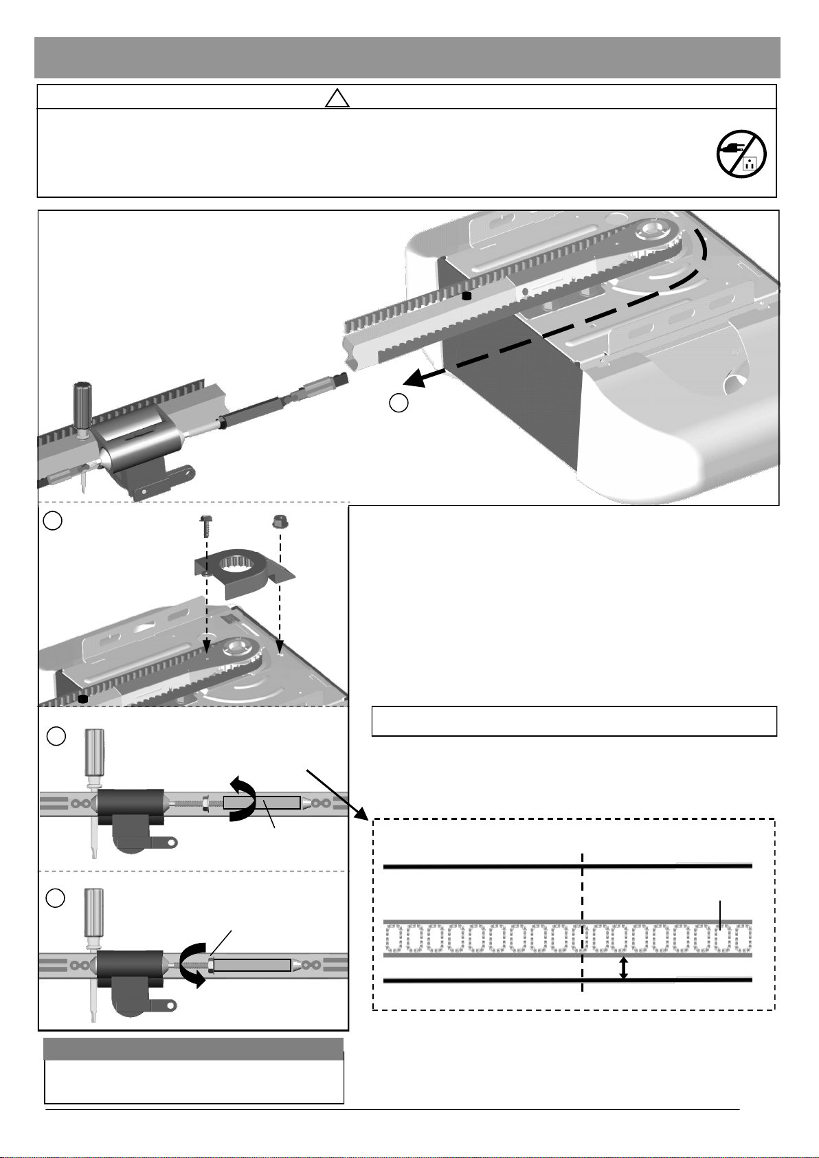
To Assemble the Header Section of Rail
See Figure 2 for steps 1 through 7.
1. Place the belt beside the rail as shown
2. Insert a screwdriver into the hole approximately 10-1/4” from
the end of the Rail - Header Segment. Slide the trolley
against this screw driver. The trolley must stay in this position for proper alignment of the belt.
3. Pass the belt end with Trolley Shaft Connector through the
slot on the Rail - Header Segment.
4. Insert the Pulley into the slot to the right of the belt.
5. Secure the Pulley by inserting the 3/8” x 1-3/4” Clevis Pin
through the top of the rail.
6. Lock the Clevis Pin with a Hitch Pin. Rotate the Pulley to
ensure it spins smoothly.
7. Connect the Trolley Shaft to the Trolley Shaft Connector on
the belt, using the Master Link Set.
8. Slide the Trolley Shaft into the Trolley until you hear a "click"
when they lock together. See Fig. 3.
Hitch Pin
3
Hitch Pin
Clevis Pin
5
Rail Bracket
Fig.1
Screwdriver
10-1/4”
Clevis Pin
Clevis Pin - 5/16” x 1-1/2”
1
2
Trolley
6
Hitch Pin
Trolley Shaft Connector
Hitch Pin
Slide trolley shaft into trolley to lock
Garage Door
7
Trolley Shaft
2
Trolley Shaft
Clevis Pin — 3/8” x 1-3/4”
Fig.2
Trolley
4
Pulley
Opener Unit
6
Fig.3
Installing the Belt
!
WARNING
To prevent SERIOUS INJURY:
- DO NOT connect power until instructed.
- Keep hands and fingers clear from sprocket during operation.
- Wear gloves when installing chain/belt and cable.
- Keep hands and fingers away from joints and possible sharp edges.
1
2
Sprocket Cover
3
4
Tighten until...
Belt Connector
Flange Nut
To Connect and Tension the Belt
1. With the trolley positioned against the screwdriver, pull the
remaining belt straight along the rail and engage belt teeth
around the sprocket. (Make sure the belt is not twisted
around the rail.) See Fig. 1.
2. After the belt is connected, attach the Sprocket Cover to the
opener with the screw and nut provided. See Fig. 2.
* VERY IMPORTANT! *
THE SPROCKET COVER MUST BE SECURELY INSTALLED!!
3. Rotate the Belt Connector towards the Trolley Shaft until the
belt is slightly loose about 1/4” (6mm) above the base of the
rail. Refer to the actual-sized illustration below for proper belt
tension. See Fig. 3.
Mid-point of rail assembly
Top of Rail
Actual Size
Belt
Tighten nut
NOTE: FOR HEAVY DOORS
For heavier doors an additional half turn to the belt
connector may be required to eliminate belt slippage.
1/4” (6mm)
Base of Rail
4. Tighten the Flange Nut on Trolley Shaft against the Belt
Connector. See Fig. 4.
Remove the screwdriver holding the trolley in position on the Rail Header Segment.
7
Important Installation Instructions
IMPORTANT INSTALLATION INSTRUCTIONS
!
WARNING
To reduce the risk of severe injury or death:
1. READ AND FOLLOW ALL INSTALLATION INSTRUCTIONS.
2. Install only on a properly balanced garage door. An improperly balanced door has the potential to inflict severe
injury. Have a qualified service person make repairs to cables, spring assemblies, and other hardware before
installing the opener.
3. Remove all ropes and remove or make inoperative all locks connected to the garage door before installing
opener.
4. Where possible, install the door opener 7 feet or more above the floor. For products having an emergency
release, mount the emergency release within reach, but at least 6 feet above the floor and avoiding contact
with vehicles to avoid accidental release.
5. Do not connect the opener to source of power until instructed to do so.
6. Locate the push button: (a) within sight of door, (b) at a minimum height of 5 feet so small children are not able
to reach it, and (c) away from all moving parts of the door.
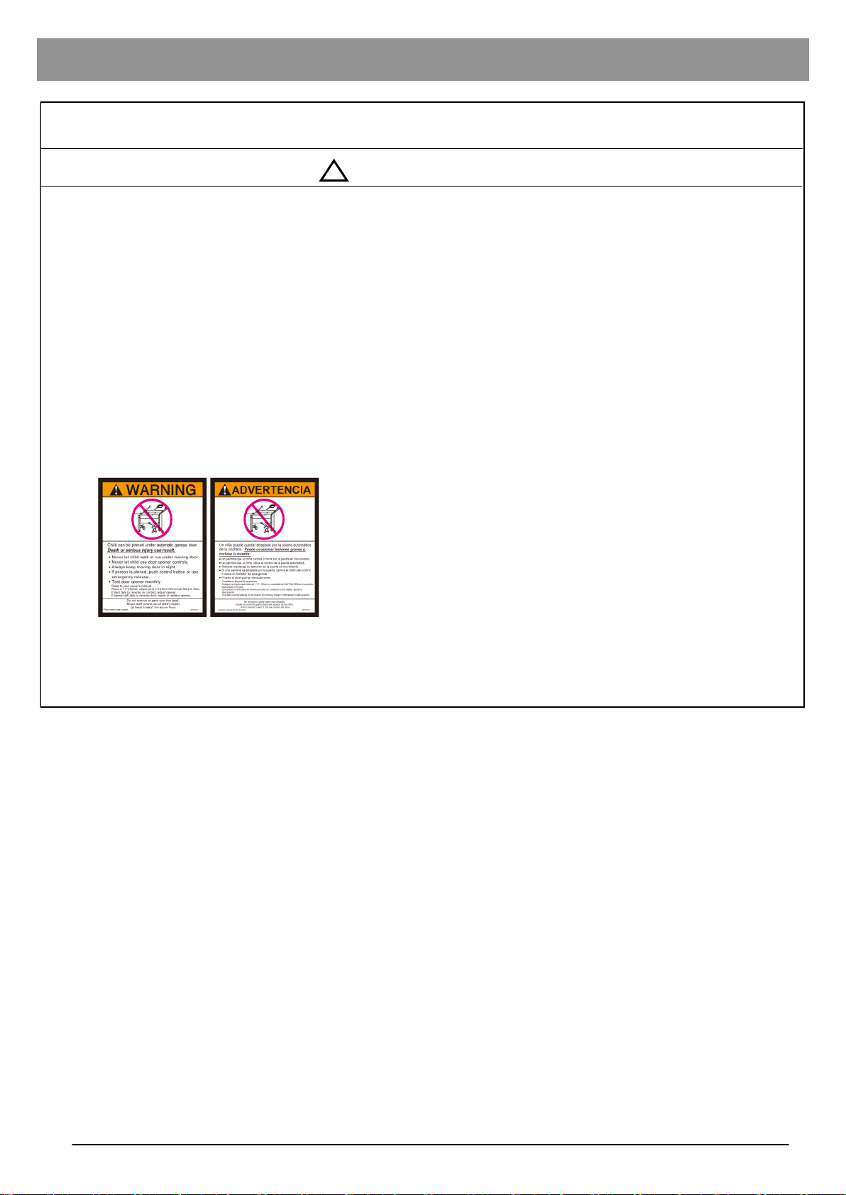
7. Install the Entrapment Warning Label next to the wall-mount push button in a prominent location. In case the
adhesive does not adhere on the surface, the label should be attached to the surface by mechanical means.
Place entrapment warning label on wall next to garage door control.
8. After installing the opener, the door must reverse when it contacts a 1-1/2-inch high object (or a 2 by 4 board
laid flat) on the floor.
8
Mounting Header Bracket
!
WARNING
To prevent SERIOUS INJURY:
- DO NOT connect power until instructed.
- The header bracket MUST be SECURELY fastened to the structural support on the mounting wall or
ceiling, otherwise the door may not reverse when required. DO NOT install the header bracket over drywall.
- Concrete anchors MUST be used when mounting the header bracket into masonry.
- NEVER try to loosen, move or adjust garage door springs, cables, pulleys, brackets, or hardware.
- Contact a qualified garage door service technician if your door binds, sticks or is unbalanced. An unbal-
anced door might not reverse when required.
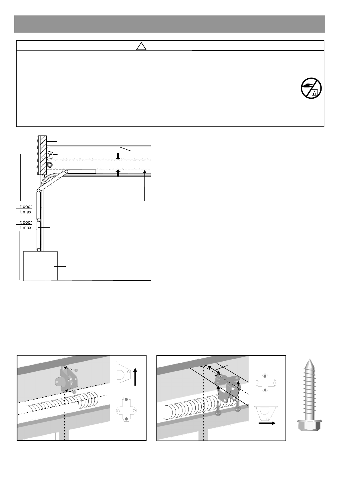
7ft door
8ft max
8ft door
9ft max
Header Wall
Header Bracket
Door Spring
Ceiling
2” (5cm) clearance
To Install Header Bracket
Note: Installation procedures may vary according to door
type.
1. While inside your garage, close the door and mark the
vertical centerline of the garage door. Extend the line onto
the header wall above the door spring.
2. Open the door to the highest point of travel. Mark a line on
MAX RAIL HEIGHT
Door Track
Highest Point of Door Travel
* VERY IMPORTANT! *
Door
Max recommended rail height from floor
7ft door = 8ft max height
8ft door = 9ft max height
the header wall 2“ (5cm) above the highest point of travel.
Note: DO NOT install the header bracket over drywall. In some
installations, it may be necessary to install a 2x4 across two wall
studs to create a suitable location for the header bracket.
If installing into masonry, use concrete anchors (not provided).
Wall-Mounting
As shown in Fig.2, place the header bracket on the vertical
centerline in direction shown.
Support block on floor
Floor
Fig.1
Mark and drill two 3/16” holes. Fasten the header bracket
securely to a structural support using two 5/16” x 1-1/2” lag
screws.
Alternative Ceiling-Mounting
Ceiling-mounting is suggested ONLY when clearance is minimal.
Horizontal Line
Highest Point of Door Travel
Fig.2 (Wall-Mounting) Fig.3 (Ceiling-Mounting)
Vertical Centerline
UP
Extend the vertical centerline onto the ceiling as shown in Fig.3.
Center the header bracket on the vertical mark, no more than
6” (15cm) from the header wall. Mark and drill holes to fasten the
header bracket securely to a structural support.
Finished Ceiling
Vertical Centerline
MAX. 6” (15cm)
OPENER
Lag Screw
5/16” x 1-1/2”
9
Attaching Rail to Header Bracket and Mounting Door Bracket
!
CAUTION
To prevent SERIOUS INJURY:
- DO NOT connect power until instructed.
- Horizontal and vertical REINFORCEMENT is needed for fiberglass, aluminum or lightweight steel garage
doors BEFORE installing the door bracket. Contact your door manufacturer for reinforcement options.
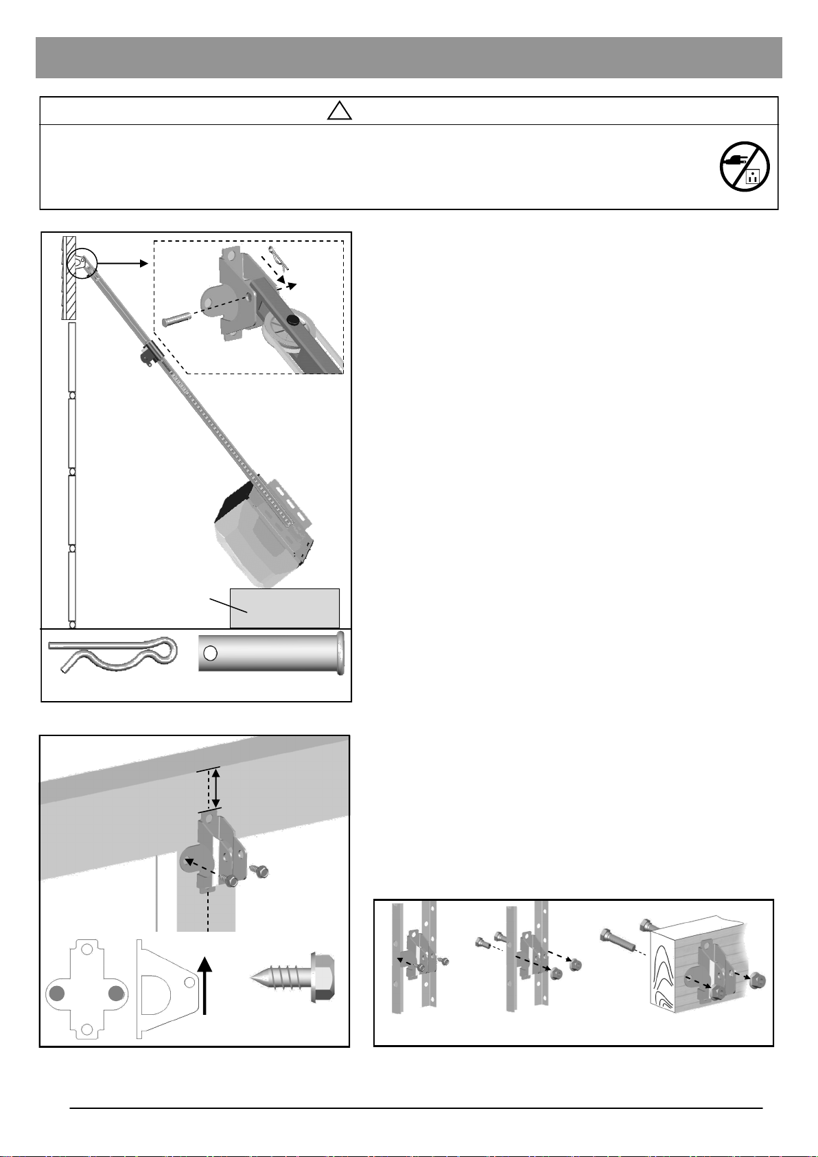
To Attach the Opener to the Header Bracket
1. As shown in Fig.1, use the packaging carton as temporary
support for the opener. Place the opener on carton to
prevent damage.
2. Align the mounting hole on the header rail to the mounting
hole on the Header Bracket.
3. Connect the header rail and the door bracket together with
a 5/16” x 1-1/2” clevis pin and lock it in place with a hitch
pin.
To mount the Door Bracket
Note: Some door reinforcement kits may provide direct
attachment of the door arm to the reinforcement bracket. If you
have a door reinforcement bracket with this option, skip this step
and proceed with the next step “mounting opener to ceiling”.
Hitch Pin
Carton
Clevis Pin - 5/16” x 1-1/2”
Fig.1
Top Edge of Door
2-4” (5-10cm)
1. Position the door bracket on the centerline of the door
approximately 2” - 4” (5-10cm) below the top edge of the
door, as shown in Fig.2.
2. Depending on the construction of your door, install using
one of the steps shown if Fig. 3 below:
For lightweight steel doors, with factory equipped
vertical steel reinforcement and horizontal strut.
(a) Mark and drill two 3/16” holes. Make sure not to drill
through the garage door. Secure the door bracket with two
1/4” x 5/8” self-threading screws (provided) as shown in
Fig.3(a).
(b) Alternative installation: Drill two 5/16” holes through the
door. Secure the door bracket using two 5/16” bolts, lock
washers and nuts (not provided) as shown in Fig.3(b). The
length of bolts will depend on the thickness of your door.
Wood door
(c) Mark and drill two 5/16” holes through the garage door.
Secure the door bracket using two 5/16” carriage bolts,
washers and nuts (not provided) as shown in Fig.3(c). The
length of bolts will depend on the thickness of your door.
Note: DO NOT use Self-Threading Screws on a wood door.
10
UP
Fig.2
Vertical Centerline of Door
Self-Threading
Screw - 1/4” x 5/8”
(a) (b) (c)
Fig.3
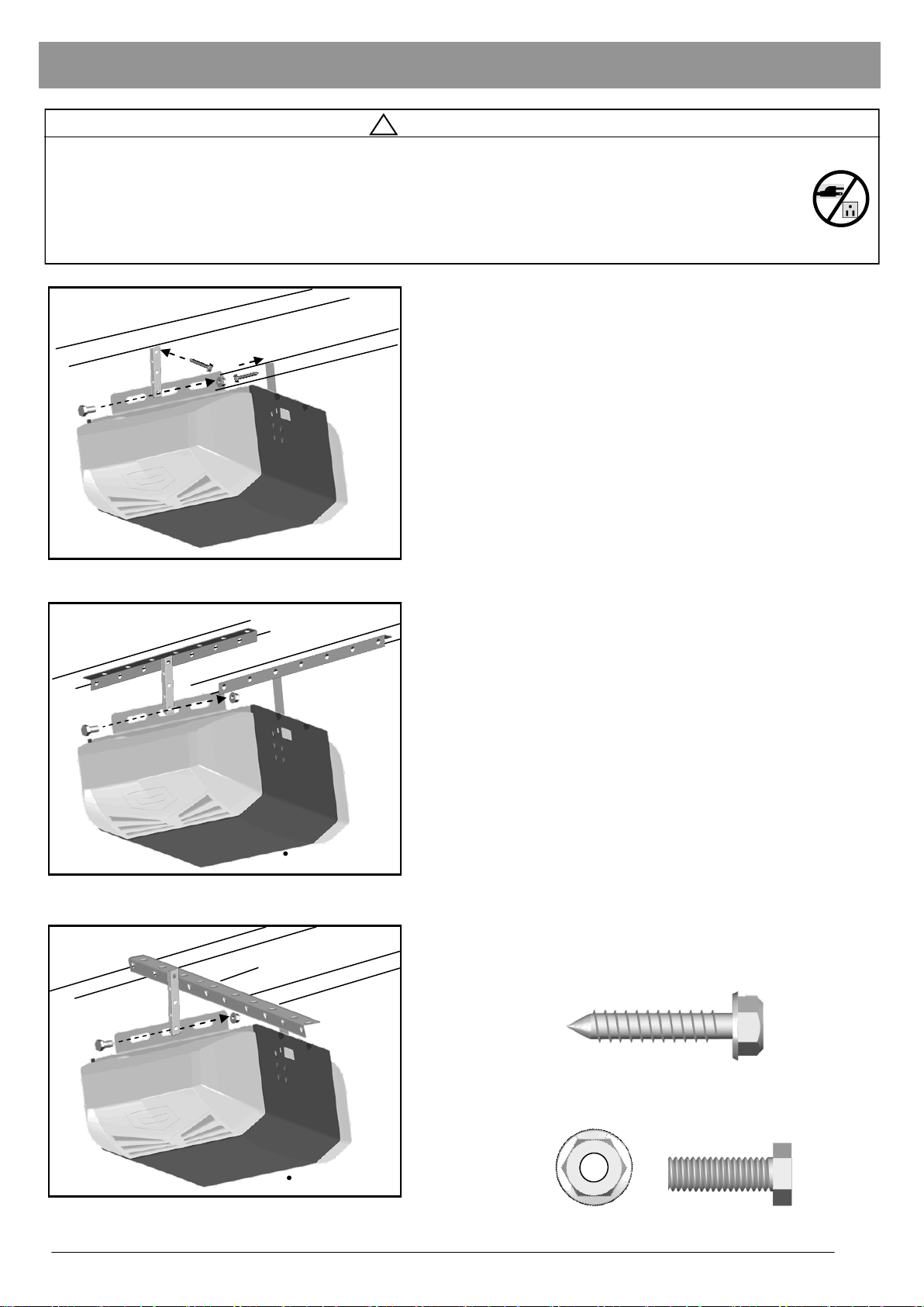
Mounting Opener to Ceiling
!
WARNING
To prevent SERIOUS INJURY or DEATH:
- DO NOT connect power until instructed.
- Install the opener at least 7 feet (2.13m) above the floor.
- Fasten the opener SECURELY to STRUCTURAL SUPPORTS of the garage to prevent falling.
- If installing brackets to masonry, concrete anchors (not provided) MUST be used.
Finished ceiling
Structural support
Fig.1
Angle Iron not provided
To Mount the Opener to Ceiling
The three most common installation options are shown in
Fig.1-3.
Fig.1 shows mounting the opener directly to structural
support on the ceiling. Fig.2 and 3 show mounting on a
finished ceiling, with heavy duty angle iron*.
*(angle iron not included)
Determine the mounting option that works best for your
application and follow installation steps below:
1. Raise the opener and rail assembly and temporarily place it
on a stepladder.
2. Position the opener and rail assembly so that it is aligned to
the center line of the garage door. If the header bracket was
mounted off center, align the opener with the header
bracket.
3. Measure the distance from each side of the opener to the
structural supports.
4. Cut both hanging brackets to appropriate length.
5. Drill 3/16” holes in the structural supports.
6. Secure one end of each of the hanging brackets to the
structural supports using 5/16” x1-1/2” lag screws
(provided).
Finished ceiling
Fig.2
Angle Iron not provided
Fig.3
Bolt / Lock Washer / Nut
not provided
Bolt / Lock Washer / Nut
not provided
7. Secure the opener to the hanging brackets and secure each
side with a 5/16” x 1” bolt and flange nut (provided).
8. Move the door manually to check clearance between
highest point of travel of the door and rail. If the door hits the
rail, raise the header bracket or adjust the mounting of
opener.
9. Remove the ladder ONLY when the opener is securely
mounted to the structural supports.
Fastening Hanging Brackets to structural supports
Lag Screw 5/16” x 1-1/2”
Securing Opener to Hanging Brackets
Bolt 5/16” x 1” Flange Nut
11
 Loading...