

Craftsman 196205680 Owner’s Manual
Owner's Manual
I (RRFTSMRN1
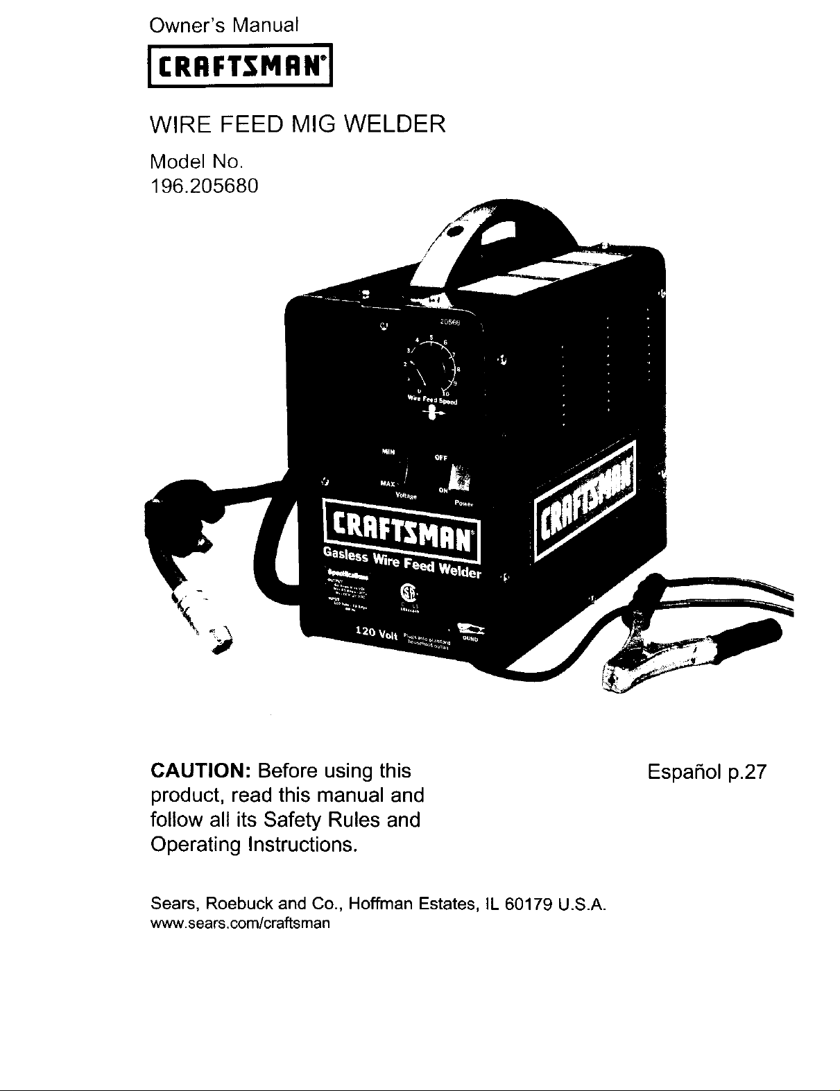
WIRE FEED MIG WELDER
Model No.
196.205680
/
CAUTION: Before using this
product, read this manual and
follow all its Safety Rules and
Operating Instructions.
Sears, Roebuck and Co., Hoffman Estates, IL 60179 U.S.A.
www.sears.com/craftsman
EspaSol p.27
Craftsman Limited Warranty ............ 2
Table Of Contents .............................. 2
Safety Summary ................................ 3
Important Safety Information ........ 3
Shock Hazards .............................. 4
Flash Hazards ................................ 4
Fire Hazards .................................. 5
Fume Hazards ................................ 6
Additional Safety Information .......... 7
Know Your Welder ............................ 8
Assembly ............................................ 9
Unpacking the Welder ...................... 9
Packing List ...................................... 9
Installing the Handle ........................ 9
Assemble the Face Shield ................ 9
Power Source Connection ................ 9
Extension Cords .............................. 10
Selecting the Welding Wire .............. 10
Install the Welding Wire .................... 10
Operation ............................................ 11
Description ........................................ 11
Duty Cycle ........................................ 11
Internal Thermal Protection .............. 12
Controls and Indicators .................... 12
Preparations for Welding .................. 12
Setting Up the Work Piece .............. 12
Preparing the Joint ............................ 12
Ground Clamp Connection .............. 13
Learning to Weld .............................. 14
Holding the Gun ................................ 14
Position the Gun to
the Work Piece ............................ 14
Distance From the Work Piece ...... 14
Laying a Bead .................................. 15
Welding Techniques .......................... 15
Traveling the Gun .......................... 15
Types of Weld Beads .................... 15
Welding Positions .......................... 16
Multiple Pass Welding .................... 17
Special Welding Methods ................ 17
Spot Welding .................................... 17
Spot Welding Instructions .............. 18
Maintenance ...................................... 18
General Maintenance ...................... 18
Consumable Maintenance .............. 18
Maintaining the Contact Tip ............ 18
Testing for a Shorted Nozzle .......... 19
Replace a Gun Liner ........................ 19
Maintaining the Welder .................... 20
Troubleshooting ................................ 20
Parts List ............................................ 22
Wiring Diagram .................................. 25
Suggested Settings .......................... 26
Limited Three-Year Warranty on Craftsman
Welder
For three years from the date of purchase, if
any part of this welder, except for the gun or
cables, fails due to a defect in material or
workmanship, return it to your nearest Sears
Parts & Repair Center, and it will be repaired
free of charge. Sears will repair the gun or
cables free of charge for only one year from
the date of purchase. This warranty does not
cover expendable parts such as contact tips
or nozzles, which are consumed during nor-
mal welder operation. This warranty applies
only while this product is used in the United
States. This warranty gives you specific legal
rights, and you may also have other rights
which vary from state to state.
Sears, Roebuck and Co., D/817WA, Hoffman
Estates, IL 60179
2
Everycraftsmanrespectsthetoolswith
whichtheywork.Theyknowthatthe tools
represent years of constantly improved
designs and developments. The true crafts-
man also knows that tools are dangerous if
misused or abused.
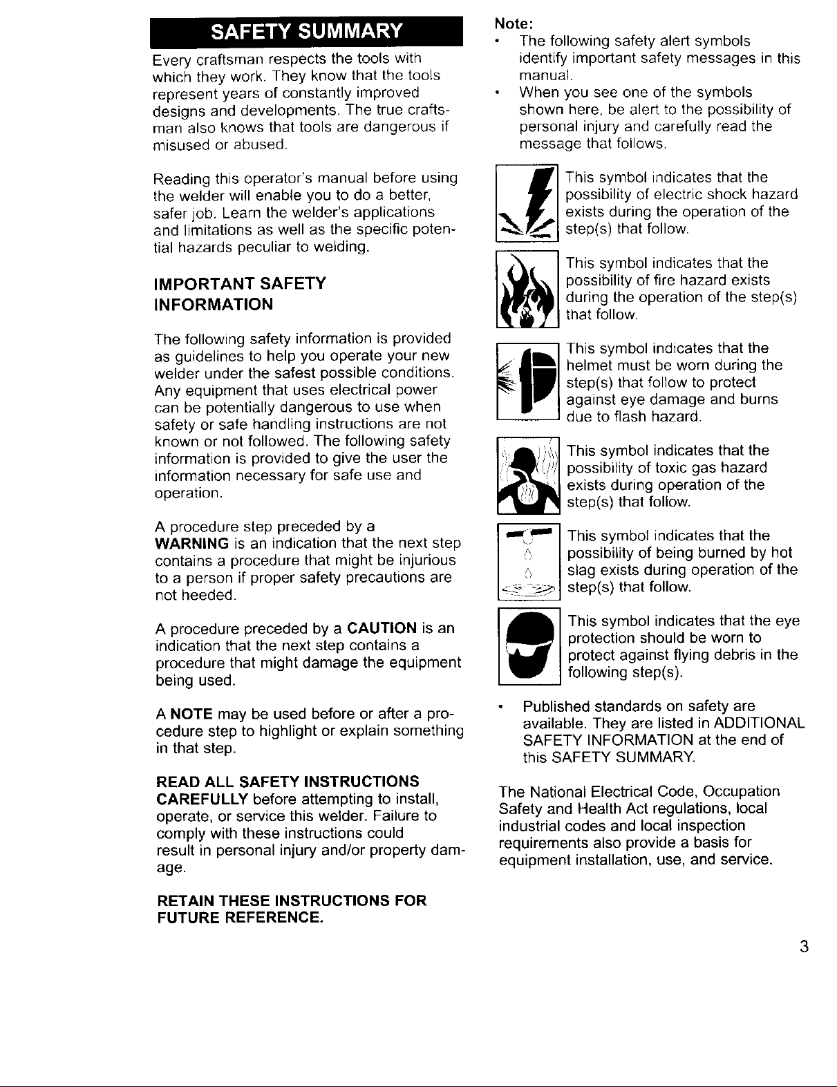
Note:
The following safety alert symbols
identify important safety messages in this
manual.
When you see one of the symbols
shown here, be alert to the possibility of
personal injury and carefully read the
message that follows.
Reading this operator's manual before using
the welder will enable you to do a better,
safer job. Learn the welder's applications
and limitations as well as the specific poten-
tial hazards peculiar to welding.
IMPORTANT SAFETY
INFORMATION
The following safety information is provided
as guidelines to help you operate your new
welder under the safest possible conditions.
Any equipment that uses electrical power
can be potentially dangerous to use when
safety or safe handling instructions are not
known or not followed. The following safety
information is provided to give the user the
information necessary for safe use and
operation.
A procedure step preceded by a
WARNING is an indication that the next step
contains a procedure that might be injurious
to a person if proper safety precautions are
not heeded.
_'] This symbol indicates that the
I possibility of electric shock hazard
,,_ Ii' I exists during the operation of the
•_J step(s) that follow.
This symbol indicates that the
possibility of fire hazard exists
during the operation of the step(s)
that follow.
This symbol indicates that the
helmet must be worn during the
step(s) that follow to protect
against eye damage and burns
due to flash hazard.
This symbol indicates that the
possibility of toxic gas hazard
exists during operation of the
step(s) that follow.
This symbol indicates that the
possibility of being burned by hot
slag exists during operation of the
step(s) that follow.
A procedure preceded by a CAUTION is an
indication that the next step contains a
procedure that might damage the equipment
being used.
A NOTE may be used before or after a pro-
cedure step to highlight or explain something
in that step.
READ ALL SAFETY INSTRUCTIONS
CAREFULLY before attempting to install,
operate, or service this welder. Failure to
comply with these instructions could
result in personal injury and/or property dam-
age.
RETAIN THESE INSTRUCTIONS FOR
FUTURE REFERENCE.
This symbol indicates that the eye
protection should be worn to
protect against flying debris in the
following step(s).
Published standards on safety are
available. They are listed in ADDITIONAL
SAFETY INFORMATION at the end of
this SAFETY SUMMARY.
The National Electrical Code, Occupation
Safety and Health Act regulations, local
industrial codes and local inspection
requirements also provide a basis for
equipment installation, use, and service.
3
SHOCK HAZARDS
I.__ ]WARN' O
ELECTRIC SHOCK CAN KILL! To reduce
the risk of death or serious injury from shock,
read, understand, and follow the following
safety instructions. In addition, make certain
that anyone else who uses this welding
equipment, or who is a bystander in the
welding area understands and follows these
safety instructions as well.
IMPORTANT! TO REDUCE THE RISK
OF DEATH, INJURY, OR PROPERTY
DAMAGE, DO NOT ATTEMPT
OPERATION of this welding equipment
until you have read and understand the
following safety summary.
Do not, in any manner, come into physical
contact with any part of the welding
current circuit. The welding current circuit
includes:
a. the work piece or any conductive
material in contact with it,
b. the ground clamp,
c. the electrode or welding wire,
d. any metal parts on the electrode
holder, or wire feed gun.
Do not weld in a damp area or come in
contact with a moist or wet surface.
Do not attempt to weld if any part of
clothing or body is wet.
Do not allow the welding equipment
to come in contact with water or
moisture.
Do not drag welding cables, wire feed
gun, or welder power cord through or
allow them to come into contact with
water or moisture.
Do not touch welder, attempt to turn
welder on or off if any part of the
body or clothing is moist or if you
are in physical contact with water or
moisture.
Do not attempt to plug the welder
into the power source if any part of body
or clothing is moist, or if you
are in physical contact with water
or moisture.
Do not connect welder work piece clamp
to or weld on electrical conduit.
Do not alter power cord or power cord
plug in any way.
Do not attempt to plug the welder
into the power source if the ground prong
on power cord plug is bent over, broken
off, or missing.
Do not allow the welder to be connected
to the power source or attempt to weld if
the welder, welding cables, welding site,
or welder power cord are exposed to any
form of atmospheric precipitation, or salt
water spray.
Do not carry coiled welding cables around
shoulders, or any other part of the body,
when they are plugged into the welder.
Do not modify any wiring, ground
connections, switches, or fuses in
this welding equipment.
Wear welding gloves to help insulate
hands from welding circuit.
Keep all liquid containers far enough
away from the welder and work area so
that if spilled, the liquid can not possibly
come in contact with any part of the
welder or electrical welding circuit.
Replace any cracked or damaged parts
that are insulated or act as
insulators such as welding cables, power
cord, or electrode holder
IMMEDIATELY.
FLASH HAZARDS
_p] WARNING
ARC RAYS CAN INJURE EYES AND BURN
SKIN! To reduce the risk of injury from arc
rays, read, understand, and follow the following
safety instructions. In addition, make certain
that anyone else that uses this welding
equipment, or is a bystander in the welding
area understands and follows these safety
instructions as well. Headshields and filter
should conform to ANSI Z87.1 standards.
Do not look at an electric arc without
proper protection. A welding arc is
extremely bright and intense and, with
inadequate or no eye protection, the
retina can be burned, leaving a
permanent dark spot in the field of vision.
4
A shieldor helmetwitha number10
shadefilterlens(minimum)mustbeused.
Donot strikea weldingarc untilall
bystandersandyou(thewelder)
haveweldingshieldsand/orhelmets
in place.
Donot wearacrackedor broken
helmetand replaceanycrackedor
brokenfilter lensesIMMEDIATELY.
Do notallowtheuninsulatedportion
ofthe wirefeedgunto touchtheground
clamporgroundedworkto preventan arc
flashfrombeingcreatedon contact.
Providebystanderswithshieldsor hel-
metsfittedwitha #10 shadefilter lens.
Wearprotectiveclothing.Theintenselight
ofthe weldingarccanburntheskin in
muchthe samewayasthesun,even
throughlight-weightclothing.Weardark
clothingof heavymaterial.Theshirtworn
shouldbelong sleevedandthe collar
keptbuttonedtoprotectchestandneck.
ProtectagainstREFLECTEDARCRAYS.
Arc rayscan bereflectedoffshiny
surfacessuchasaglossypainted
surface,aluminum,stainlesssteel,and
glass.It is possiblefor youreyesto be
injuredbyreflectedarc raysevenwhen
wearinga protectivehelmetor shield.If
weldingwitha reflectivesurfacebehind
you,arc rayscanbounceoff the surface,
thenoff thefilterlensontheinsideof
your helmetor shield,thenintoyoureyes.
Ifareflectivebackgroundexistsin your
weldingarea,eitherremoveitor coverit
withsomethingnon-flammableandnon-
reflective.Reflectivearcrayscanalso
causeskinburninadditiontoeye injury.
FIRE HAZARDS
WARNING
FIRE OR EXPLOSION CAN CAUSE
DEATH, INJURY, AND PROPERTY
DAMAGE! To reduce the risk of death, injury,
or property damage from fire or explosion,
read, understand, and follow the following
safety instructions. In addition, make certain
that anyone else that uses this welding
equipment, or is a bystander in the welding
area, understands and follows these safety
instructions as well. REMEMBER! Arc weld-
ing by nature produces sparks, hot spatter,
molten metal drops, hot slag, and hot metal
parts that can start fires, burn skin, and
damage eyes.
Do not wear gloves or other clothing
that contains oil, grease, or other
flammable substances.
Do not wear flammable hair
preparations.
Do not weld in an area until it is checked
and cleared of combustible and/or flam-
mable materials. BE AWARE that sparks
and slag can fly 35 feet and can pass
through small cracks and openings. If
work and combustibles cannot be sepa-
rated by a minimum of 35 feet, protect
against ignition with suitable, snug-fitting,
fire resistant, covers or shields.
Do not weld on walls until checking for
and removing combustibles touching the
other side of the walls.
Do not weld, cut, or perform other such
work on used barrels, drums, tanks, or
other containers that had contained a
flammable or toxic substance. The tech-
niques for removing flammable
substance and vapors, to make a used
container safe for welding or cutting, are
quite complex and require special
education and training.
Do not strike an arc on a compressed
gas or air cylinder or other pressure ves-
sel. Doing so will create a brittle area that
can result in a violent rupture
immediately or at a later time as
a result of rough handling.
Do not weld or cut in an area where the
air may contain flammable dust (such as
grain dust), gas, or liquid vapors (such as
gasoline).
Do not handle hot metal, such as the
work piece or electrode stubs, with bare
hands.
Wear leather gloves, heavy long sleeve
shirt, cuffless trousers, high-topped
shoes, helmet, and cap. As necessary,
use additional protective clothing such as
leather jacket or sleeves, fire resistant
leggings, or apron. Hot sparks or metal
can lodge in rolled up sleeves, trouser
cuffs, or pockets. Sleeves and collars
should be kept buttoned and pockets
5
eliminated from the shirt front.
Have fire extinguisher equipment handy
for immediate use! A portable chemical
fire extinguisher, type ABC, is
recommended.
Wear ear plugs when welding overhead
to prevent spatter or slag from falling
into ear.
Make sure welding area has a good,
solid, safe floor, preferably concrete or
masonry, not tiled, carpeted, or made of
any other flammable material.
Protect flammable walls, ceilings,
and floors with heat resistant covers
or shields.
Check welding area to make sure it
is free of sparks, glowing metal or slag,
and flames before leaving the welding
area.
FUME HAZARDS
WARNING
FUMES, GASSES, AND VAPORS CAN
CAUSE DISCOMFORT, ILLNESS, AND
DEATH! To reduce the risk of discomfort, ill-
ness, or death, read, understand, and follow
the following safety instructions. In addition,
make certain that anyone else that uses this
welding equipment or is a bystander in the
welding area, understands and follows these
safety instructions as well.
advice and inspection of the ventilation of
the welding area. These metals produce
EXTREMELY TOXIC fumes which can
cause discomfort, illness, and death.
Do not weld or cut in areas that are near
chlorinated solvents. Vapors from chlori-
nated hydrocarbons, such as
trichloroethylene and perchloroethylene,
can be decomposed by the heat of an
electric arc or its ultraviolet radiation.
These actions can cause PHOSGENE, a
HIGHLY TOXIC gas to form, along with
other lung and eye-irritating gasses. Do
not weld or cut where these solvent
vapors can be drawn into the work area
or where the ultraviolet radiation can pen
etrate to areas containing even very
small amounts of these vapors.
Do not weld in a confined area unless it
is being ventilated or the operator (and
anyone else in the area) is wearing an
air-supplied respirator.
Stop welding if you develop momentary
eye, nose, or throat irritation as this indi-
cates inadequate ventilation. Stop work
and take necessary steps to improve
ventilation in the welding area. Do not
resume welding if physical discomfort
persists.
Do not weld in an area until it is checked
for adequate ventilation as described in
ANSI standard #Z49.1. If ventilation is
not adequate to exchange all fumes and
gasses generated during the welding
process with fresh air, do not weld unless
you (the welder) and all bystanders are
wearing air-supplied respirators.
Do not heat metals coated with, or that
contain, materials that produce toxic
fumes (such as galvanized steel), unless
the coating is removed. Make certain the
area is well ventilated, and the operator
and all bystanders are wearing air-sup-
plied respirators.
Do not weld, cut, or heat lead, zinc,
cadmium, mercury, beryllium, or similar
metals without seeking professional
6
ADDITIONAL SAFETY
INFORMATION
For additional information concerning
welding safety, refer to the following
standards and comply with them as
applicable.
ANSI Standard Z49.1 SAFETY IN
WELDING AND CUTTING - obtainable
from the American Welding Society, 550
NW Le Jeune Road, Miami, FL 33126
Telephone (800) 443-9353,
Fax (305) 443-7559 - www.amweld.org
or www.aws.org
ANSI Standard Z87.1 - SAFE PRAC-
TICE FOR OCCUPATION AND EDUCA-
TIONAL EYE AND FACE PROTECTION
- obtainable from the American National
Standards Institute, 11 West 42nd St.,
New York, NY 10036
Telephone (212) 642-4900,
Fax (212) 398-0023 - www.ansi.org
NFPA Standard 51B - CUTTING AND
WELDING PROCESS - obtainable from
the National Fire Protection Association,
1 Batterymarch Park, P.O. Box 9101,
Quincy, MA 02269-9101
Telephone (617) 770-3000
Fax (617) 770-0700 - www.nfpa.org
OSHA Standard 29 CFR, Part 1910,
Subpart Q., WELDING, CUTTING AND
BRAZING - obtainable from your state
OSHA office or U.S. Dept. of Labor
OSHA, Office of Public Affairs, Room
N3647, 200 Constitution Ave.,
Washington, DC 20210 - www.osha.gov
CSA Standard W117.2 - Code for SAFE-
TY IN WELDING AND CUTTING. -
obtainable from Canadian Standards
Association, 178 Rexdale Blvd.,
Etobicoke, Ontario M9W 1R3 -
www.csa.ca
American Welding Society Standard
A6.0. WELDING AND CUTTING CON-
TAINERS WHICH HAVE HELD COM-
BUSTIBLES. - obtainable from the
American Welding Society, 550 NW Le
Jeune Road, Miami, FL 33126
Telephone (800) 443-9353,
Fax (305) 443-7559 - www.amweld.org
or www.aws.org
7
Wire Speed
Gun Cable
J
Welding
Gun
Voltage Clamp
Selector Gr( und
Handle
Cable
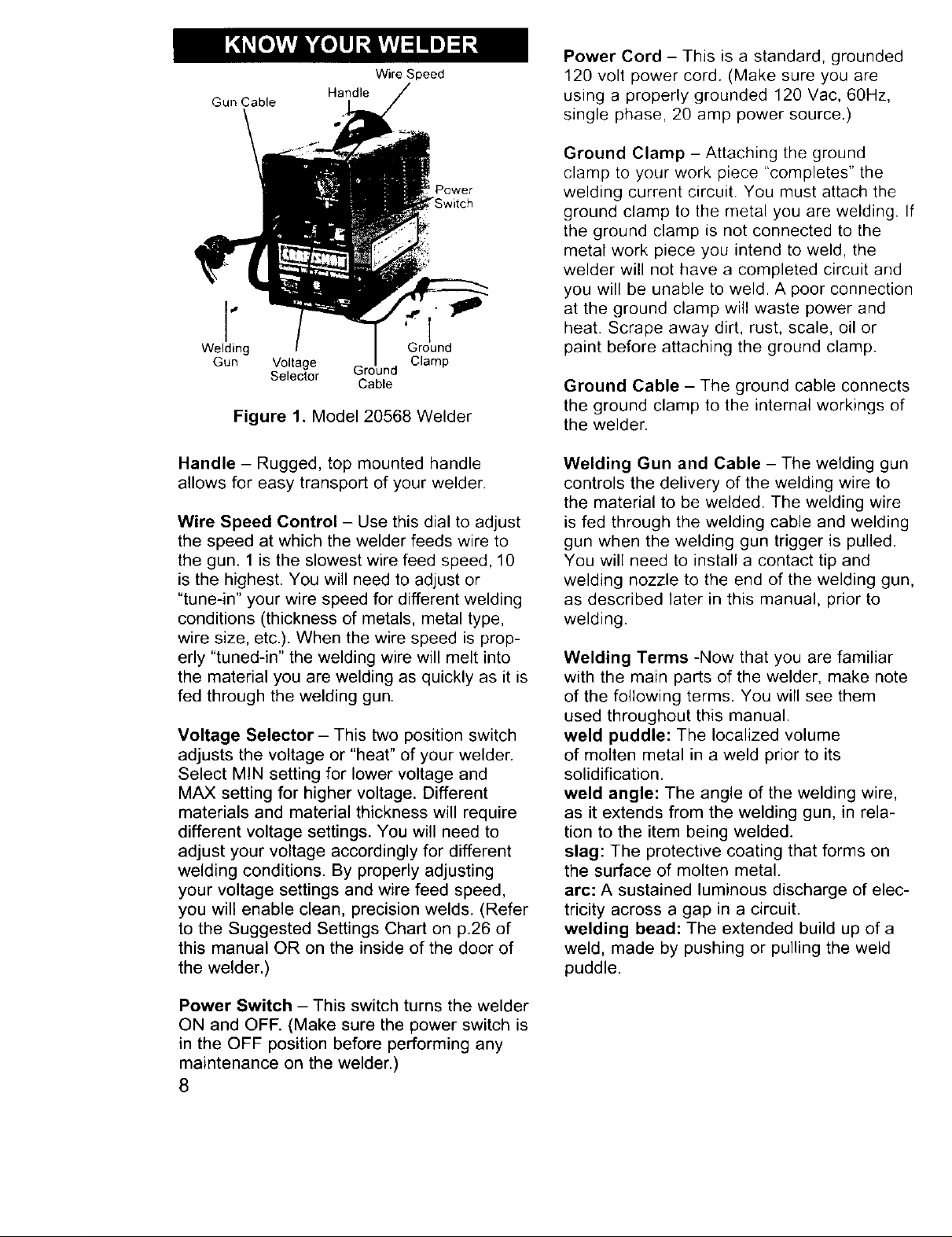
Figure 1. Model 20568 Welder
Power
"Switch
Power Cord - This is a standard, grounded
120 volt power cord. (Make sure you are
using a properly grounded 120 Vac, 60Hz,
single phase, 20 amp power source.)
Ground Clamp - Attaching the ground
clamp to your work piece "completes" the
welding current circuit. You must attach the
ground clamp to the metal you are welding. If
the ground clamp is not connected to the
metal work piece you intend to weld, the
welder will not have a completed circuit and
you will be unable to weld. A poor connection
at the ground clamp will waste power and
heat. Scrape away dirt, rust, scale, oil or
paint before attaching the ground clamp.
Ground Cable - The ground cable connects
the ground clamp to the internal workings of
the welder.
Handle - Rugged, top mounted handle
allows for easy transport of your welder.
Wire Speed Control - Use this dial to adjust
the speed at which the welder feeds wire to
the gun. 1 is the slowest wire feed speed, 10
is the highest. You will need to adjust or
"tune-in" your wire speed for different welding
conditions (thickness of metals, metal type,
wire size, etc.). When the wire speed is prop-
erly "tuned-in" the welding wire will melt into
the material you are welding as quickly as it is
fed through the welding gun.
Voltage Selector - This two position switch
adjusts the voltage or "heat" of your welder.
Select MIN setting for lower voltage and
MAX setting for higher voltage. Different
materials and material thickness will require
different voltage settings. You will need to
adjust your voltage accordingly for different
welding conditions. By properly adjusting
your voltage settings and wire feed speed,
you will enable clean, precision welds. (Refer
to the Suggested Settings Chart on p.26 of
this manual OR on the inside of the door of
the welder.)
Welding Gun and Cable - The welding gun
controls the delivery of the welding wire to
the material to be welded. The welding wire
is fed through the welding cable and welding
gun when the welding gun trigger is pulled.
You will need to install a contact tip and
welding nozzle to the end of the welding gun,
as described later in this manual, prior to
welding.
Welding Terms -Now that you are familiar
with the main parts of the welder, make note
of the following terms. You will see them
used throughout this manual.
weld puddle: The localized volume
of molten metal in a weld prior to its
solidification.
weld angle: The angle of the welding wire,
as it extends from the welding gun, in rela-
tion to the item being welded.
slag: The protective coating that forms on
the surface of molten metal.
arc: A sustained luminous discharge of elec-
tricity across a gap in a circuit.
welding bead: The extended build up of a
weld, made by pushing or pulling the weld
puddle.
Power Switch - This switch turns the welder
ON and OFF. (Make sure the power switch is
in the OFF position before performing any
maintenance on the welder.)
8
Thefollowingproceduresdescribetheprocess
requiredtoassemble,install,maintain,andpre-
paretoweldwithyournewwirefeedacwelder.
UNPACKING THE WELDER
1. Removeanycartonsor bagscontaining
parts/accessories.(Mostpartsare
shippedinsidethewelderdoor.)
2. Openthecartonsorbagspackedwithyour
welderandinspecttheircontentsfordamage.
3. Layoutthe partsandcomparethemto
thethepackinglistinTable1to
familiarizeyourselfwiththepartsand
whattheyare called.Thiswill helpyou
whenreadingthemanual.
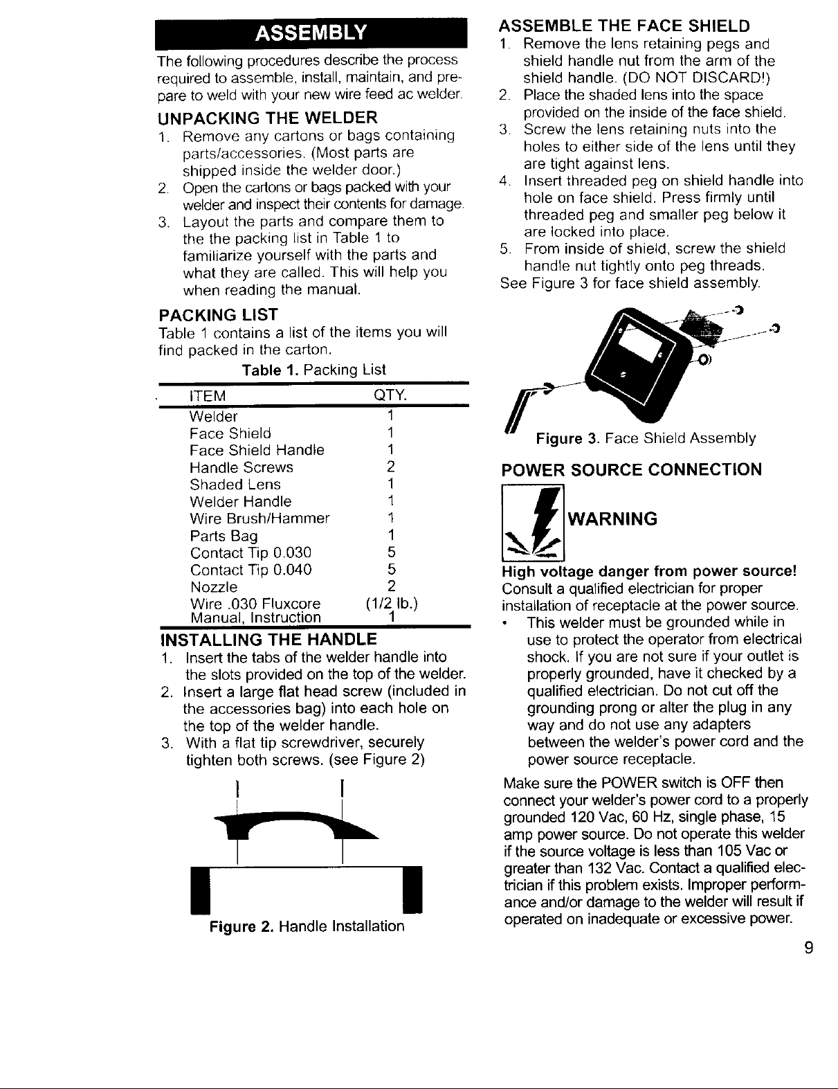
PACKING LIST
Table 1 contains a list of the items you will
find packed in the carton.
Table 1. Packing List
ITEM QTY.
Welder 1
Face Shield 1
Face Shield Handle 1
Handle Screws 2
Shaded Lens 1
Welder Handle 1
Wire Brush/Hammer 1
Parts Bag 1
Contact Tip 0.030 5
Contact Tip 0.040 5
Nozzle 2
Wire .030 Fluxcore (1/2lb.)
Manual, Instruction
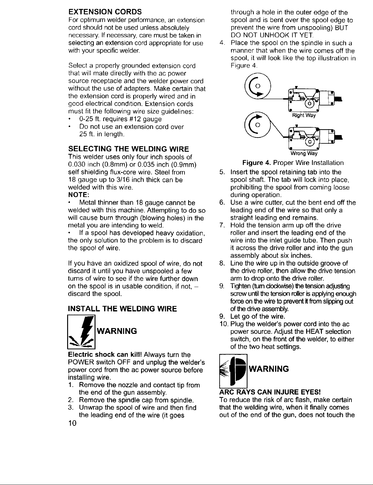
INSTALLING THE HANDLE
1. Insert the tabs of the welder handle into
the slots provided on the top of the welder.
2. Insert a large flat head screw (included in
the accessories bag) into each hole on
the top of the welder handle.
3. With a flat tip screwdriver, securely
tighten both screws. (see Figure 2)
1
I 1
! !
Figure 2. Handle Installation
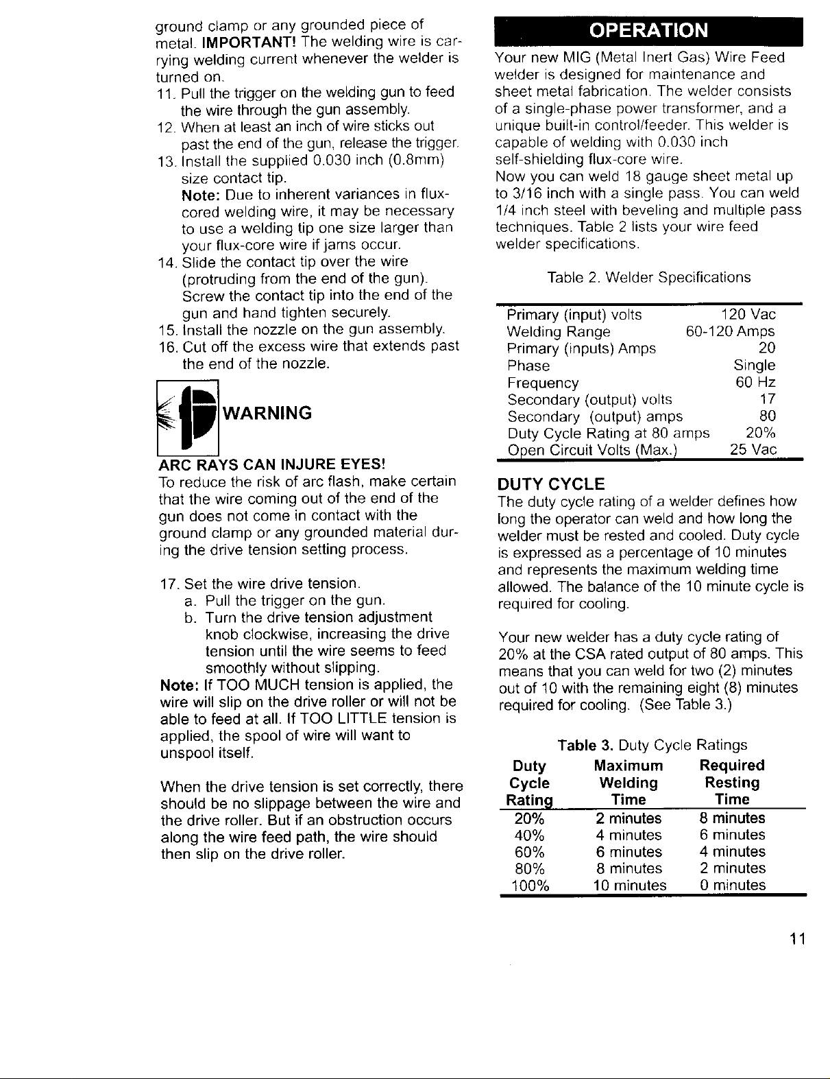
ASSEMBLE THE FACE SHIELD
1. Remove the lens retaining pegs and
shield handle nut from the arm of the
shield handle. (DO NOT DISCARD!)
2. Place the shaded lens into the space
provided on the inside of the face shield.
3. Screw the lens retaining nuts into the
holes to either side of the lens until they
are tight against lens.
4. Insert threaded peg on shield handle into
hole on face shield. Press firmly until
threaded peg and smaller peg below it
are locked into place.
5. From inside of shield, screw the shield
handle nut tightly onto peg threads.
See Figure 3 for face shield assembly.
Figure 3. Face Shield Assembly
POWER SOURCE CONNECTION
High voltage danger from power source!
Consult a qualified electrician for proper
installation of receptacle at the power source.
This welder must be grounded while in
use to protect the operator from electrical
shock. If you are not sure if your outlet is
properly grounded, have it checked by a
qualified electrician. Do not cut off the
grounding prong or alter the plug in any
way and do not use any adapters
between the welder's power cord and the
power source receptacle.
Make sure the POWER switch is OFF then
connect your welder's power cord to a properly
grounded 120 Vac, 60 Hz, single phase, 15
amp power source. Do not operate this welder
if the source voltage is less than 105 Vac or
greater than 132 Vac. Contact a qualified elec-
trician if this problem exists. Improper perform-
ance and/or damage to the welder will result if
operated on inadequate or excessive power.
9
EXTENSION CORDS
For optimum welder performance, an extension
cord should not be used unless absolutely
necessary. If necessary, care must be taken in
selecting an extension cord appropriate for use
with your specific welder.
Select a properly grounded extension cord
that will mate directly with the ac power
source receptacle and the welder power cord
without the use of adapters. Make certain that
the extension cord is properly wired and in
good electrical condition. Extension cords
must fit the following wire size guidelines:
0-25 ft. requires #12 gauge
Do not use an extension cord over
25 ft. in length.
through a hole in the outer edge of the
spool and is bent over the spool edge to
prevent the wire from unspooling) BUT
DO NOT UNHOOK IT YET.
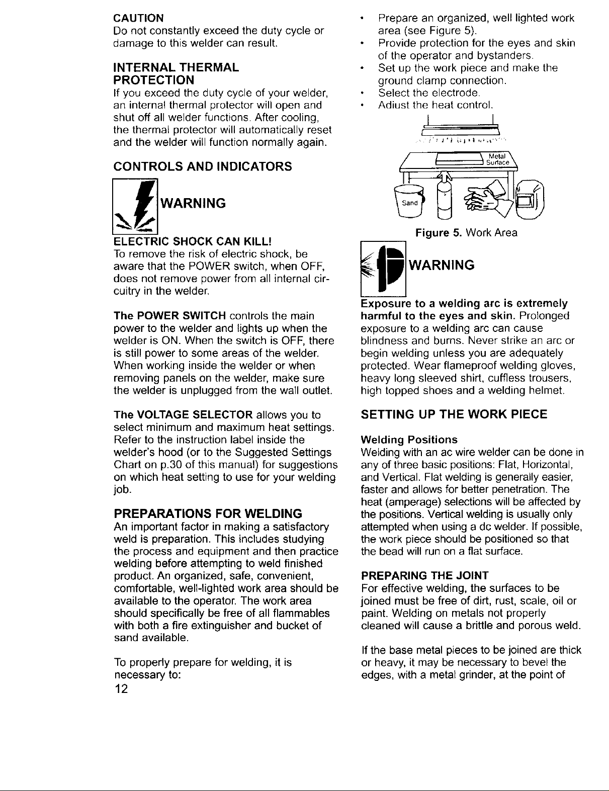
.
Place the spool on the spindle in such a
manner that when the wire comes off the
spool, it will look like the top illustration in
Figure 4.
SELECTING THE WELDING WIRE
This welder uses only four inch spools of
0.030 inch (0.8mm) or 0.035 inch (0.9mm)
self shielding flux-core wire. Steel from
18 gauge up to 3/16 inch thick can be
welded with this wire.
NOTE:
Metal thinner than 18 gauge cannot be
welded with this machine. Attempting to do so
will cause burn through (blowing holes) in the
metal you are intending to weld.
If a spool has developed heavy oxidation,
the only solution to the problem is to discard
the spool of wire.
If you have an oxidized spool of wire, do not
discard it until you have unspooled a few
turns of wire to see if the wire further down
on the spool is in usable condition, if not, -
discard the spool.
INSTALL THE WELDING WIRE
Electric shock can kill! Always turn the
POWER switch OFF and unplug the welder's
power cord from the ac power source before
installing wire.
1. Remove the nozzle and contact tip from
the end of the gun assembly.
2. Remove the spindle cap from spindle.
3. Unwrap the spool of wire and then find
the leading end of the wire (it goes
10
Wrong Way
Figure 4. Proper Wire Installation
5. Insert the spool retaining tab into the
spool shaft. The tab will lock into place,
prohibiting the spool from coming loose
during operation.
6. Use a wire cutter, cut the bent end off the
leading end of the wire so that only a
straight leading end remains.
7. Hold the tension arm up off the drive
roller and insert the leading end of the
wire into the inlet guide tube. Then push
it across the drive roller and into the gun
assembly about six inches.
8. Line the wire up in the outside groove of
the drive roller, then allow the drive tension
arm to drop onto the drive roller.
9. Tighten (turn clockwise) the tension adjusting
screw until the tension roller is applying enough
force on the wire to prevent it from slipping out
of the drive assembly.
9. Let go of the wire.
10. Plug the welder's power cord into the ac
power source. Adjust the HEAT selection
switch, on the front of the welder, to either
of the two heat settings.
ARC RAYS CAN INJURE EYES!
To reduce the risk of arc flash, make certain
that the welding wire, when it finally comes
out of the end of the gun, does not touch the
ground clamp or any grounded piece of
metal. IMPORTANT! The welding wire is car-
rying welding current whenever the welder is
turned on.
11. Pull the trigger on the welding gun to feed
the wire through the gun assembly.
12. When at least an inch of wire sticks out
past the end of the gun, release the trigger.
13. Install the supplied 0.030 inch (0.8mm)
size contact tip.
Note: Due to inherent variances in flux-
cored welding wire, it may be necessary
to use a welding tip one size larger than
your flux-core wire if jams occur.
14. Slide the contact tip over the wire
(protruding from the end of the gun).
Screw the contact tip into the end of the
gun and hand tighten securely.
15. Install the nozzle on the gun assembly.
16. Cut off the excess wire that extends past
the end of the nozzle.
ARC RAYS CAN INJURE EYES!
To reduce the risk of arc flash, make certain
that the wire coming out of the end of the
gun does not come in contact with the
ground clamp or any grounded material dur-
ing the drive tension setting process.
17. Set the wire drive tension.
a. Pull the trigger on the gun.
b. Turn the drive tension adjustment
knob clockwise, increasing the drive
tension until the wire seems to feed
smoothly without slipping.
Note: If TOO MUCH tension is applied, the
wire will slip on the drive roller or will not be
able to feed at all. If TOO LITTLE tension is
applied, the spool of wire will want to
unspool itself.
When the drive tension is set correctly, there
should be no slippage between the wire and
the drive roller. But if an obstruction occurs
along the wire feed path, the wire should
then slip on the drive roller.
Your new MIG (Metal Inert Gas) Wire Feed
welder is designed for maintenance and
sheet metal fabrication. The welder consists
of a single-phase power transformer, and a
unique built-in control/feeder. This welder is
capable of welding with 0.030 inch
self-shielding flux-core wire.
Now you can weld 18 gauge sheet metal up
to 3/16 inch with a single pass. You can weld
1/4 inch steel with beveling and multiple pass
techniques. Table 2 lists your wire feed
welder specifications.
Table 2. Welder Specifications
Primary (input) volts 120 Vac
Welding Range 60-120 Amps
Primary (inputs) Amps 20
Phase Single
Frequency 60 Hz
Secondary (output) volts 17
Secondary (output) amps 80
Duty Cycle Rating at 80 amps 20%
Open Circuit Volts/Max.! 25 Vac
DUTY CYCLE
The duty cycle rating of a welder defines how
long the operator can weld and how long the
welder must be rested and cooled. Duty cycle
is expressed as a percentage of 10 minutes
and represents the maximum welding time
allowed. The balance of the 10 minute cycle is
required for cooling.
Your new welder has a duty cycle rating of
20% at the CSA rated output of 80 amps. This
means that you can weld for two (2) minutes
out of 10 with the remaining eight (8) minutes
required for cooling. (See Table 3.)
Table 3. Duty Cycle Ratings
Duty Maximum Required
Cycle Welding Resting
Rating Time Time
20% 2 minutes 8 minutes
40% 4 minutes 6 minutes
60% 6 minutes 4 minutes
80% 8 minutes 2 minutes
100% 10 minutes 0 minutes
11
CAUTION
Do not constantly exceed the duty cycle or
damage to this welder can result.
INTERNAL THERMAL
PROTECTION
If you exceed the duty cycle of your welder,
an internal thermal protector will open and
shut off all welder functions. After cooling,
the thermal protector will automatically reset
and the welder will function normally again.
CONTROLS AND INDICATORS
_ WARNING
ELECTRIC SHOCK CAN KILL!
To remove the risk of electric shock, be
aware that the POWER switch, when OFF,
does not remove power from all internal cir-
cuitry in the welder.
The POWER SWITCH controls the main
power to the welder and lights up when the
welder is ON. When the switch is OFF, there
is still power to some areas of the welder.
When working inside the welder or when
removing panels on the welder, make sure
the welder is unplugged from the wall outlet.
Prepare an organized, well lighted work
area (see Figure 5).
Provide protection for the eyes and skin
of the operator and bystanders.
Set up the work piece and make the
ground clamp connection.
Select the electrode.
Adiust the heat control.
I I
Figure 5. Work Area
_1 WARNING
Exposure to a welding arc is extremely
harmful to the eyes and skin. Prolonged
exposure to a welding arc can cause
blindness and burns. Never strike an arc or
begin welding unless you are adequately
protected. Wear flameproof welding gloves,
heavy long sleeved shirt, cuffless trousers,
high topped shoes and a welding helmet.
The VOLTAGE SELECTOR allows you to
select minimum and maximum heat settings.
Refer to the instruction label inside the
welder's hood (or to the Suggested Settings
Chart on p.30 of this manual) for suggestions
on which heat setting to use for your welding
job.
PREPARATIONS FOR WELDING
An important factor in making a satisfactory
weld is preparation. This includes studying
the process and equipment and then practice
welding before attempting to weld finished
product. An organized, safe, convenient,
comfortable, well-lighted work area should be
available to the operator. The work area
should specifically be free of all flammables
with both a fire extinguisher and bucket of
sand available.
To properly prepare for welding, it is
necessary to:
12
SETTING UP THE WORK PIECE
Welding Positions
Welding with an ac wire welder can be done in
any of three basic positions: Flat, Horizontal,
and Vertical. Flat welding is generally easier,
faster and allows for better penetration. The
heat (amperage) selections will be affected by
the positions. Vertical welding is usually only
attempted when using a dc welder. If possible,
the work piece should be positioned so that
the bead will run on a flat surface.
PREPARING THE JOINT
For effective welding, the surfaces to be
joined must be free of dirt, rust, scale, oil or
paint. Welding on metals not properly
cleaned will cause a brittle and porous weld.
If the base metal pieces to be joined are thick
or heavy, it may be necessary to bevel the
edges, with a metal grinder, at the point of
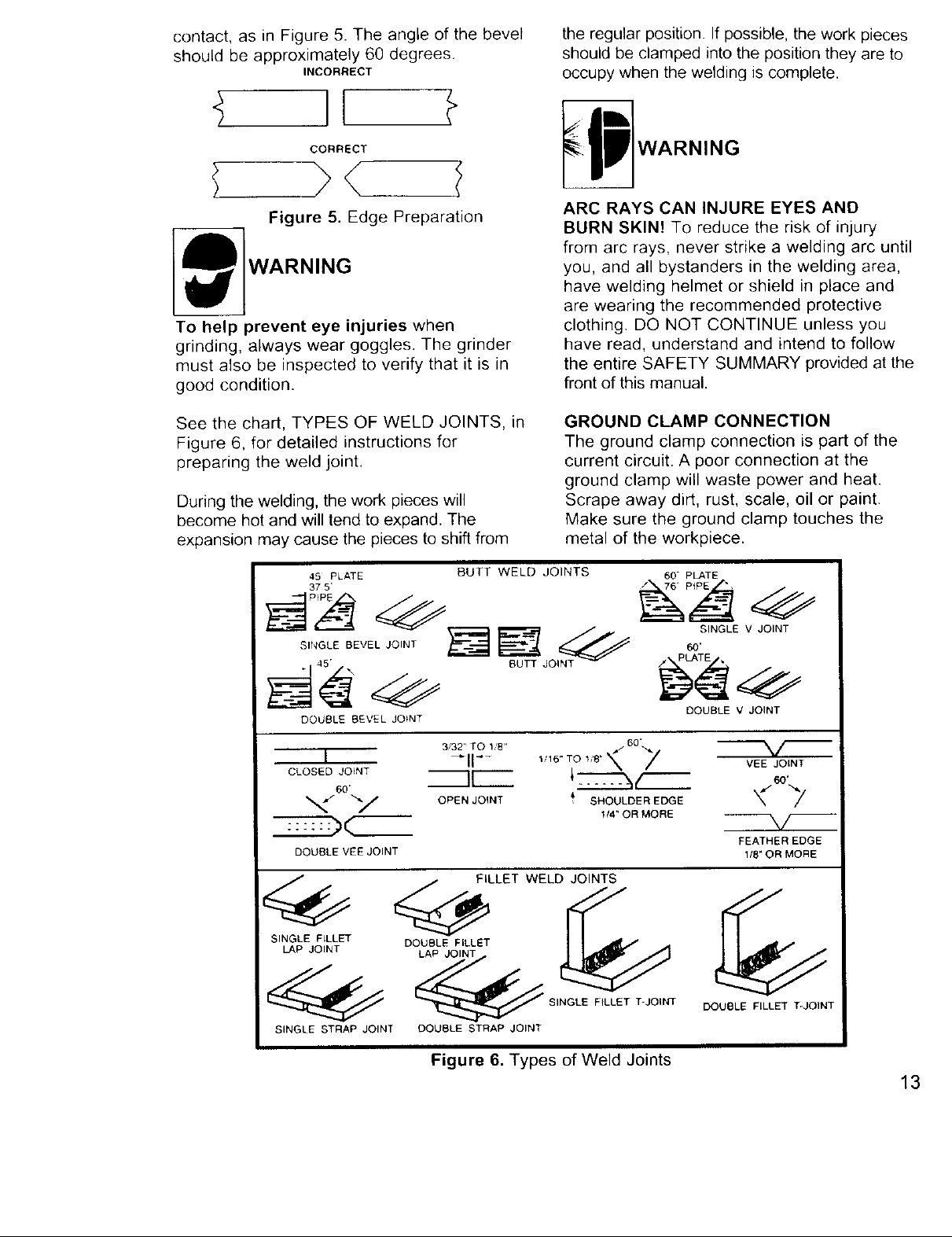
contact,asin Figure5.Theangleof the bevel
shouldbeapproximately60degrees.
INCORRECT
CORRECT
)< /
Figure 5. Edge Preparation
WARNING
To help prevent eye injuries when
grinding, always wear goggles. The grinder
must also be inspected to verify that it is in
good condition.
the regular position. If possible, the work pieces
should be clamped into the position they are to
occupy when the welding is complete.
ARC RAYS CAN INJURE EYES AND
BURN SKIN! To reduce the risk of injury
from arc rays, never strike a welding arc until
you, and all bystanders in the welding area,
have welding helmet or shield in place and
are wearing the recommended protective
clothing. DO NOT CONTINUE unless you
have read, understand and intend to follow
the entire SAFETY SUMMARY provided at the
front of this manual.
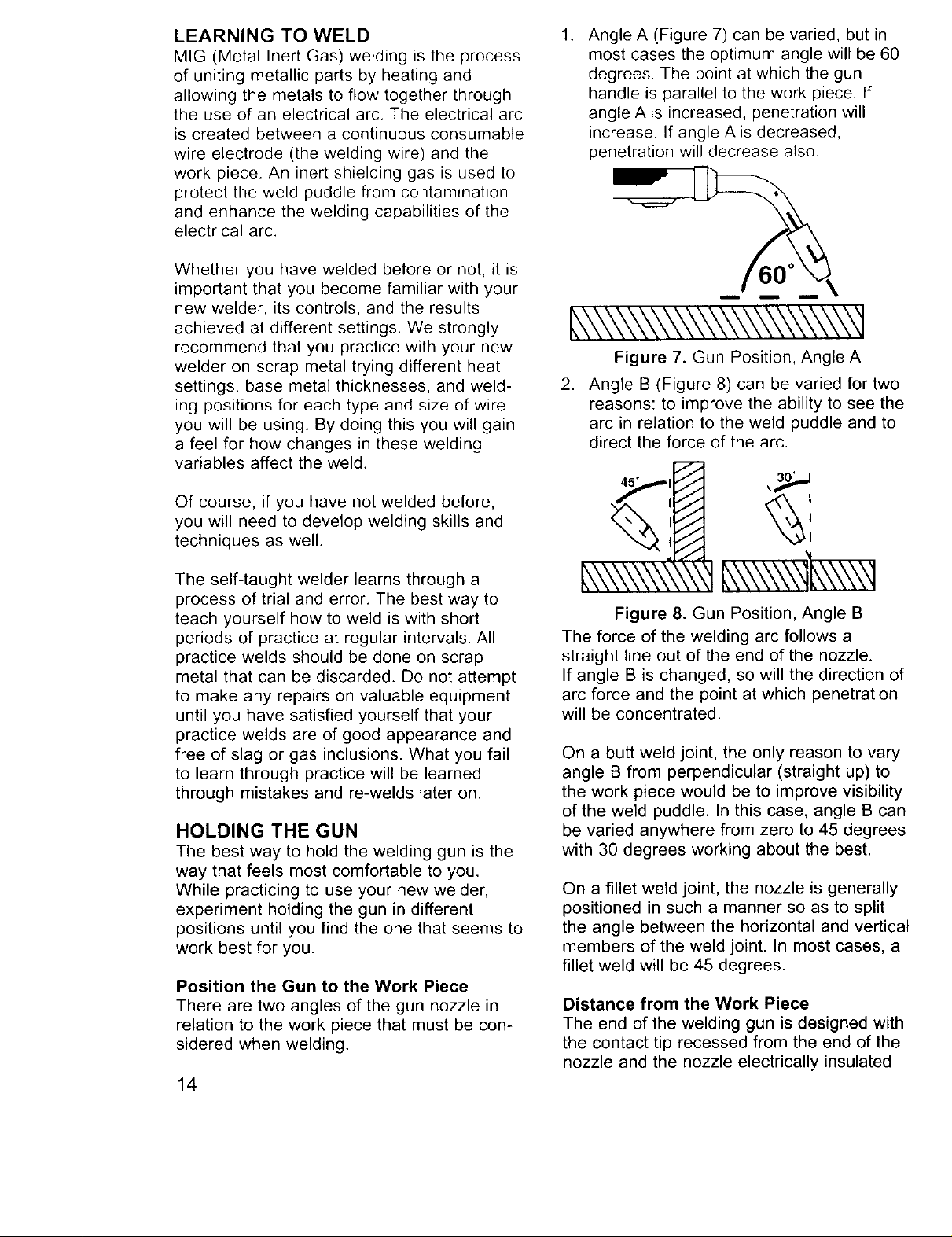
See the chart, TYPES OF WELD JOINTS, in
Figure 6, for detailed instructions for
preparing the weld joint.
During the welding, the work pieces will
become hot and will tend to expand. The
expansion may cause the pieces to shift from
45 PLATE BUTT WELD JOINTS
37 5'
DOUBLE BEVEL JOfNT
I --I1"- VEEJOINT
CLOSED JOINT I[ _o.
60.
_,/ "*-/ OPEN JOINT _' SHOULDER EDGE _" _//
DOUBLE VEE JOINT 1/8" OR MORE
3/32" TO YB" 1/16" TO 118' *_
GROUND CLAMP CONNECTION
The ground clamp connection is part of the
current circuit. A poor connection at the
ground clamp will waste power and heat.
Scrape away dirt, rust, scale, oil or paint.
Make sure the ground clamp touches the
metal of the workpiece.
" PLATE
SINGLE V JOINT
60"
DOUBLE V JOINT
FEATHER EDGE
FILLET WELDJOINT_
_ SINGLE F{LLET T-JOINT DOUBLE FILLET T-JOINT
SINGLE STRAP JOINT DOUBLE STRAP JOINT
Figure 6. Types of Weld Joints
13
LEARNING TO WELD
MIG (Metal Inert Gas) welding is the process
of uniting metallic parts by heating and
allowing the metals to flow together through
the use of an electrical arc. The electrical arc
is created between a continuous consumable
wire electrode (the welding wire) and the
work piece. An inert shielding gas is used to
protect the weld puddle from contamination
and enhance the welding capabilities of the
electrical arc.
Whether you have welded before or not, it is
important that you become familiar with your
new welder, its controls, and the results
achieved at different settings. We strongly
recommend that you practice with your new
welder on scrap metal trying different heat
settings, base metal thicknesses, and weld-
ing positions for each type and size of wire
you will be using. By doing this you will gain
a feel for how changes in these welding
variables affect the weld.
Of course, if you have not welded before,
you will need to develop welding skills and
techniques as well.
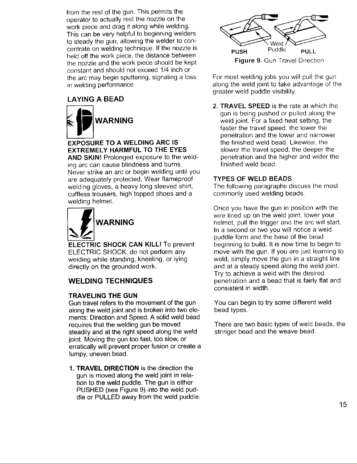
1. Angle A (Figure 7) can be varied, but in
most cases the optimum angle will be 60
degrees. The point at which the gun
handle is parallel to the work piece. If
angle A is increased, penetration will
increase. If angle A is decreased,
penetration will decrease also.
L\\\\\\\\\\\\\\\\\\\\\\\q
Figure 7. Gun Position, Angle A
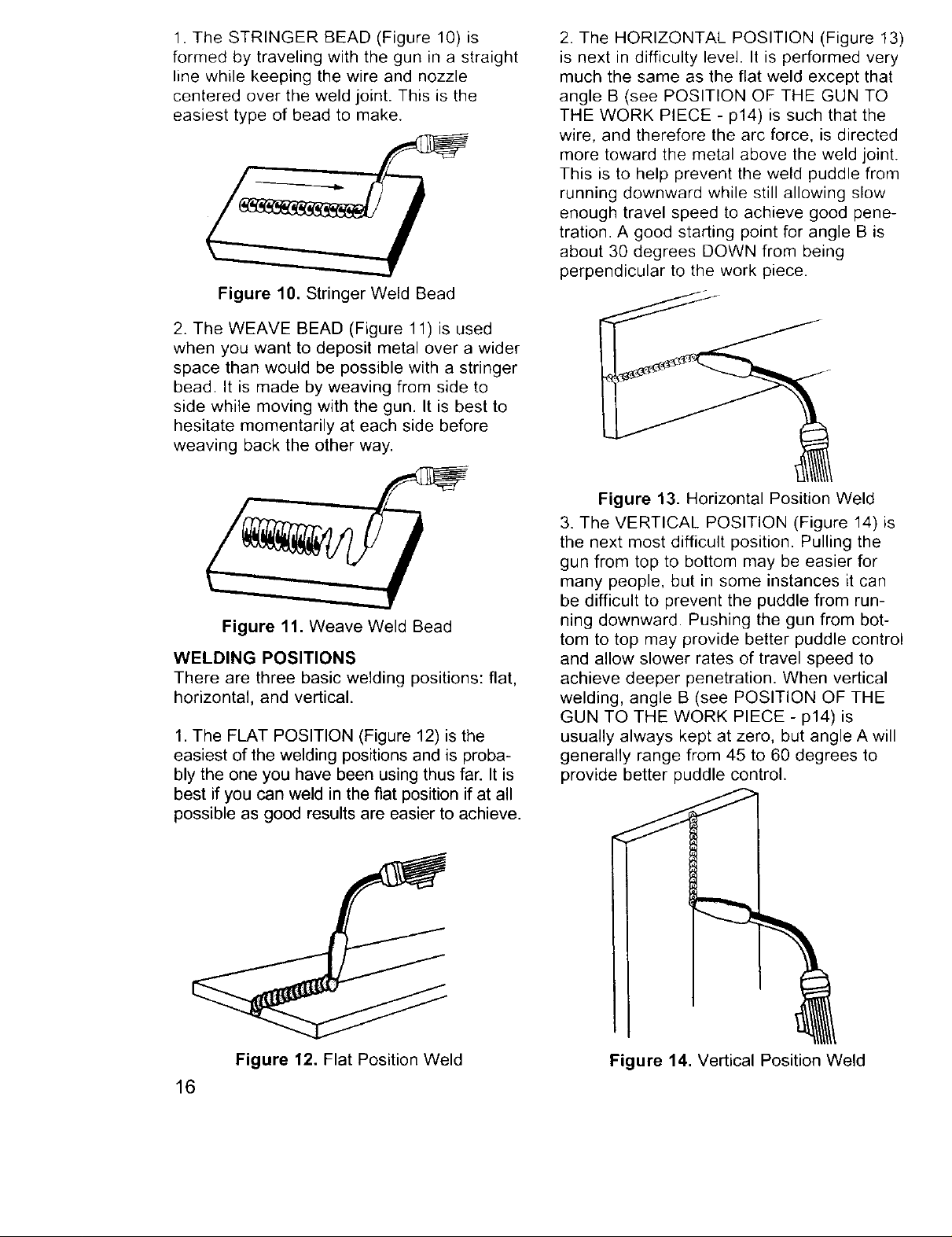
.
Angle B (Figure 8) can be varied for two
reasons: to improve the ability to see the
arc in relation to the weld puddle and to
direct the force of the arc.
45 ° I
The self-taught welder learns through a
process of trial and error. The best way to
teach yourself how to weld is with short
periods of practice at regular intervals. All
practice welds should be done on scrap
metal that can be discarded. Do not attempt
to make any repairs on valuable equipment
until you have satisfied yourself that your
practice welds are of good appearance and
free of slag or gas inclusions. What you fail
to learn through practice will be learned
through mistakes and re-welds later on.
HOLDING THE GUN
The best way to hold the welding gun is the
way that feels most comfortable to you.
While practicing to use your new welder,
experiment holding the gun in different
positions until you find the one that seems to
work best for you.
Position the Gun to the Work Piece
There are two angles of the gun nozzle in
relation to the work piece that must be con-
sidered when welding.
14
#,\\\\\\\\\\\'t
Figure 8. Gun Position, Angle B
The force of the welding arc follows a
straight line out of the end of the nozzle.
If angle B is changed, so will the direction of
arc force and the point at which penetration
will be concentrated.
Qn a butt weld joint, the only reason to vary
angle B from perpendicular (straight up) to
the work piece would be to improve visibility
of the weld puddle. In this case, angle B can
be varied anywhere from zero to 45 degrees
with 30 degrees working about the best.
On a fillet weld joint, the nozzle is generally
positioned in such a manner so as to split
the angle between the horizontal and vertical
members of the weld joint. In most cases, a
fillet weld will be 45 degrees.
Distance from the Work Piece
The end of the welding gun is designed with
the contact tip recessed from the end of the
nozzle and the nozzle electrically insulated
fromtherestofthe gun.Thispermitsthe
operatorto actuallyrestthenozzleonthe
workpieceanddragitalongwhilewelding.
Thiscanbeveryhelpfultobeginningwelders
to steadythe gun,allowingthewelderto con-
centrateonweldingtechnique.Ifthe nozzleis
heldoffthe workpiece,thedistancebetween
thenozzleandtheworkpieceshouldbekept
constantandshouldnotexceed1/4inchor
thearcmaybeginsputtering,signalinga loss
inweldingperformance
LAYING A BEAD
EXPOSURE TO A WELDING ARC IS
EXTREMELY HARMFUL TO THE EYES
AND SKIN! Prolonged exposure to the weld-
ing arc can cause blindness and burns.
Never strike an arc or begin welding until you
are adequately protected. Wear flameproof
welding gloves, a heavy long sleeved shirt,
cuffless trousers, high topped shoes and a
welding helmet.
_ WARNING
ELECTRIC SHOCK CAN KILL! To prevent
ELECTRIC SHOCK, do not perform any
welding while standing, kneeling, or lying
directly on the grounded work.
WELDING TECHNIQUES
TRAVELING THE GUN
Gun travel refers to the movement of the gun
along the weld joint and is broken into two ele-
ments: Direction and Speed. A solid weld bead
requires that the welding gun be moved
steadily and at the right speed along the weld
joint. Moving the gun too fast, too slow, or
erratically will prevent proper fusion or create a
lumpy, uneven bead.
PUSH Puddle PULL
Figure 9. Gun Travel Direction
For most welding jobs you will pull the gun
along the weld joint to take advantage of the
greater weld puddle visibility.
, TRAVEL SPEED is the rate at which the
gun is being pushed or pulled along the
weld joint. For a fixed heat setting, the
faster the travel speed, the lower the
penetration and the lower and narrower
the finished weld bead. Likewise, the
slower the travel speed, the deeper the
penetration and the higher and wider the
finished weld bead.
TYPES OF WELD BEADS
The following paragraphs discuss the most
commonly used welding beads.
Once you have the gun in position with the
wire lined up on the weld joint, lower your
helmet, pull the trigger and the arc will start.
In a second or two you will notice a weld
puddle form and the base of the bead
beginning to build. It is now time to begin to
move with the gun. If you are just learning to
weld, simply move the gun in a straight line
and at a steady speed along the weld joint.
Try to achieve a weld with the desired
penetration and a bead that is fairly flat and
consistent in width.
You can begin to try some different weld
bead types.
There are two basic types of weld beads, the
stringer bead and the weave bead.
1. TRAVEL DIRECTION is the direction the
gun is moved along the weld joint in rela-
tion to the weld puddle. The gun is either
PUSHED (see Figure 9) into the weld pud-
dle or PULLED away from the weld puddle.
15
1. The STRINGER BEAD (Figure 10) is
formed by traveling with the gun in a straight
line while keeping the wire and nozzle
centered over the weld joint. This is the
easiest type of bead to make.
Figure 10. Stringer Weld Bead
2. The WEAVE BEAD (Figure 11) is used
when you want to deposit metal over a wider
space than would be possible with a stringer
bead. It is made by weaving from side to
side while moving with the gun. It is best to
hesitate momentarily at each side before
weaving back the other way.
2. The HORIZONTAL POSITION (Figure 13)
is next in difficulty level. It is performed very
much the same as the flat weld except that
angle B (see POSITION OF THE GUN TO
THE WORK PIECE - p14) is such that the
wire, and therefore the arc force, is directed
more toward the metal above the weld joint.
This is to help prevent the weld puddle from
running downward while still allowing slow
enough travel speed to achieve good pene-
tration. A good starting point for angle B is
about 30 degrees DOWN from being
perpendicular to the work piece.
Figure 11. Weave Weld Bead
WELDING POSITIONS
There are three basic welding positions: flat,
horizontal, and vertical.
1. The FLAT POSITION (Figure 12) is the
easiest of the welding positions and is proba-
bly the one you have been using thus far. It is
best if you can weld in the fiat position if at all
possible as good results are easier to achieve.
Figure 13. Horizontal Position Weld
3. The VERTICAL POSITION (Figure 14) is
the next most difficult position. Pulling the
gun from top to bottom may be easier for
many people, but in some instances it can
be difficult to prevent the puddle from run-
ning downward. Pushing the gun from bot-
tom to top may provide better puddle control
and allow slower rates of travel speed to
achieve deeper penetration. When vertical
welding, angle B (see POSITION OF THE
GUN TO THE WORK PIECE - p14) is
usually always kept at zero, but angle A will
generally range from 45 to 60 degrees to
provide better puddle control.
16
Figure 12. Flat Position Weld
Figure 14. Vertical Position Weld
 Loading...