

Craftsman 196205070 Owner’s Manual
IB-205070
Owner's Manual
I CRRFTSMRN1
220V PLASMA CUTTER
Model No.
196.205070
CAUTION: Before using this
product, read this manual and
follow all its Safety Rules and
Operating Instructions.
Sears, Roebuck and Co., Hoffman Estates, IL 60179 U.S.A.
www.sears.com/craftsman
Espa_ol p.23
Craftsman Limited Warranty .............. 2
Introduction ........................................ 2
Safety Summary .................................. 3
Safety Information .............................. 3
Shock Hazards .................................. 4
Flash Hazards .................................... 4
Fire Hazards ...................................... 5
Plasma Arc Hazards .......................... 6
Fume Hazards .................................... 6
Additional Safety Information ............ 7
Plasma Cutter Specifications ............ 8
Description ........................................ 8
Operating Characteristics .................. 8
Duty Cycle ........................................ 8
Internal Thermal Protection .............. 8
Pneumatic Protection ...................... 8
Electric Shock Protection ................ 8
Know Your Plasma Cutter .................. 9
Plasma Cutter Installation .................. 10
Site Selection .................................... 10
Power Source Connection ................ 10
Power Requirements ........................ 10
Connect to Power Source ................ 10
Extension Cords .............................. 10
Assembling the Plasma Cutter .......... 10
Unpacking the Plasma Cutter .......... 10
Packing List...................................... 10
Assemble the Face Shield .............. 11
Installing the Handle ........................ 11
Operation ............................................ 11
Connecting the Air Supply .................. 11
Connecting the Ground Clamp to the
Workpiece .......................................... 12
Powering Up the Unit ........................ 12
Principles of Plasma Cutting .............. 12
Learning to Plasma Cut ...................... 12
Holding the Torch ............................ 13
Position the Torch to the Workpiece 13
Cutting ................................................ 13
Piercing .............................................. 14
Recommended Cutting Speeds ........ 14
Maintenance ........................................ 15
Draining Condensation ...................... 15
Replacing the Nozzle ........................ 15
Replacing the Electrode .................... 16
Replacing the Swirl Ring .................... 16
Replacing the Nozzle Cap .................. 16
Troubleshooting .................................. 16
Wiring Diagram .................................... 18
Parts List .............................................. 19
Limited Three-Year Warranty on Craftsman Plasma Cutter
For three years from the date of purchase, if any part of this plasma cutter, except for the gun
or cables, fails due to a defect in material or workmanship, return it to your nearest Sears Parts
& Repair Center, and it will be repaired free of charge. Sears will repair the gun or cables free
of charge for only one year from the date of purchase. This warranty does not cover expend-
able parts such as electrodes, nozzles or nozzle caps, which are consumed during normal
plasma cutter operation. This warranty applies only while this product is used in the United
States. This warranty gives you specific legal rights, and you may also have other rights which
vary from state to state.
Sears, Roebuck and Co., D/817WA, Hoffman Estates, IL 60179
This owner's manual provides all of the specific information you need to safely and effectively use
your Plasma Cutter. It contains instructions on safety, set-up, installation and actual Plasma Cutter
operation.
Everycraftsmanrespectsthetoolswith
whichtheywork.Theyknowthatthetools
representyearsofconstantlyimproved
designsanddevelopments,Thetrue
craftsmanalsoknowsthattoolsare
dangerousifmisusedorabused,
Readingthisoperator'smanualbeforeusing
theplasmacutterwiltenableyoutodoabet-
ter,saferjob.Learntheplasmacutter's
applicationsandlimitationsasweltasthe
specificpotentialhazardspeculiartoplasma
cutting.
IMPORTANT SAFETY
INFORMATION
The following safety information is provided
as guidelines to help you operate your new
plasma cutter under the safest possible con-
ditions. Any equipment that uses electrical
power can be potentially dangerous to use
when safety or safe handling instructions are
not known or not followed. The following
safety information is provided to give the
user the information necessary for safe use
and operation.
A procedure step preceded by a
WARNING is an indication that the next step
contains a procedure that might be injurious
to a person if proper safety precautions are
not heeded,
A procedure step preceded by a CAUTION
is an indication that the next step contains a
procedure that might damage the equipment
being used,
A NOTE may be used before or after a
procedure step to highlight or explain
something in that step.
READ ALL SAFETY INSTRUCTIONS
CAREFULLY before attempting to install,
operate, or service this plasma cutter. Failure
to comply with these instructions could result
in personal injury and/or property damage.
RETAIN THESE INSTRUCTIONS FOR
FUTURE REFERENCE.
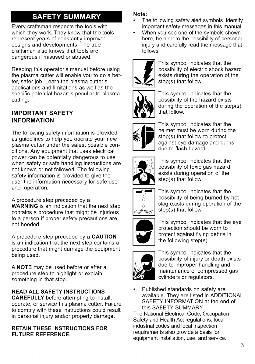
Note:
• The following safety alert symbols identify
important safety messages in this manual.
• When you see one of the symbols shown
here, be alert to the possibility of personal
injury and carefully read the message that
follows.
This symbol indicates that the
possibility of electric shock hazard
exists during the operation of the
step(s) that follow.
This symbol indicates that the
possibility of fire hazard exists
during the operation of the step(s)
that follow.
This symbol indicates that the
helmet must be worn during the
step(s) that follow to protect
against eye damage and burns
due to flash hazard.
This symbol indicates that the
possibility of toxic gas hazard
exists during operation of the
step(s) that follow.
This symbol indicates that the
possibility of being burned by hot
slag exists during operation of the
step(s) that follow.
This symbol indicates that the eye
protection should be worn to
protect against flying debris in
the following step(s).
This symbol indicates that the
possibility of injury or death exists
due to improper handling and
maintenance of compressed gas
cylinders or regulators.
Published standards on safety are
available. They are listed in ADDITIONAL
SAFETY INFORMATION at the end of
this SAFETY SUMMARY.
The National Electrical Code, Occupation
Safety and Health Act regulations, local
industrial codes and local inspection
requirements also provide a basis for
equipment installation, use, and service.
3
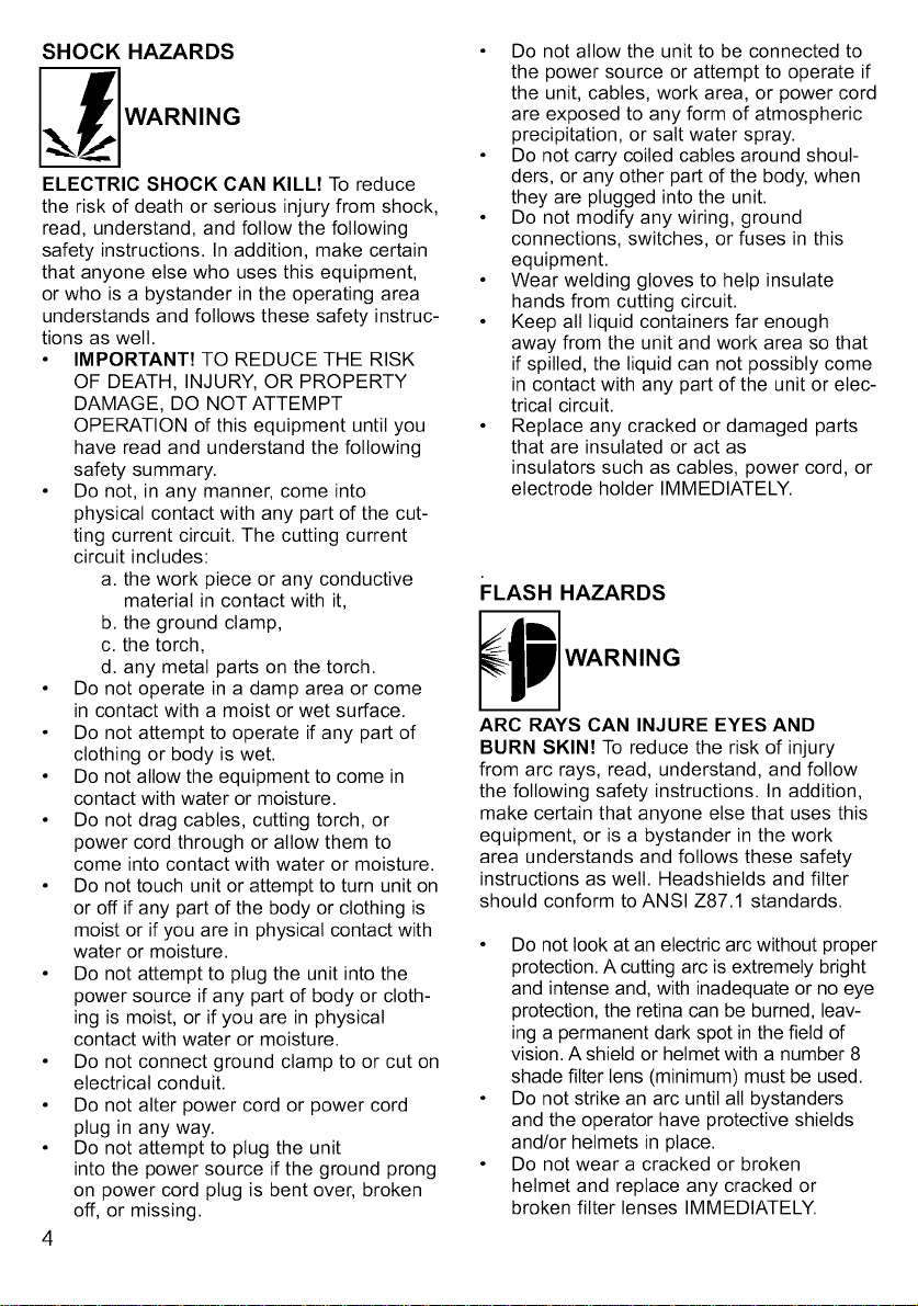
SHOCK HAZARDS
WARNING
ELECTRIC SHOCK CAN KILLt To reduce
the risk of death or serious injury from shock,
read, understand, and follow the following
safety instructions. In addition, make certain
that anyone else who uses this equipment,
or who is a bystander in the operating area
understands and follows these safety instruc-
tions as welt.
• IMPORTANT! TO REDUCE THE RISK
OF DEATH, INJURY, OR PROPERTY
DAMAGE, DO NOT ATTEMPT
OPERATION of this equipment until you
have read and understand the following
safety summary.
• Do not, in any manner, come into
physical contact with any part of the cut-
ting current circuit. The cutting current
circuit includes:
a. the work piece or any conductive
material in contact with it,
b. the ground clamp,
c. the torch,
d. any metal parts on the torch.
• Do not operate in a damp area or come
in contact with a moist or wet surface.
• Do not attempt to operate if any part of
clothing or body is wet.
• Do not allow the equipment to come in
contact with water or moisture.
• Do not drag cables, cutting torch, or
power cord through or allow them to
come into contact with water or moisture.
• Do not touch unit or attempt to turn unit on
or off if any part of the body or clothing is
moist or if you are in physical contact with
water or moisture.
• Do not attempt to plug the unit into the
power source ifany part of body or cloth-
ing is moist, or if you are in physical
contact with water or moisture.
• Do not connect ground clamp to or cut on
electrical conduit.
• Do not alter power cord or power cord
plug in any way.
• Do not attempt to plug the unit
into the power source if the ground prong
on power cord plug is bent over, broken
off, or missing.
• Do not allow the unit to be connected to
the power source or attempt to operate if
the unit, cables, work area, or power cord
are exposed to any form of atmospheric
precipitation, or salt water spray.
• Do not carry coiled cables around shoul-
ders, or any other part of the body, when
they are plugged into the unit.
• Do not modify any wiring, ground
connections, switches, or fuses in this
equipment.
• Wear welding gloves to help insulate
hands from cutting circuit.
• Keep all liquid containers far enough
away from the unit and work area so that
if spilled, the liquid can not possibly come
in contact with any part of the unit or elec-
trical circuit.
• Replace any cracked or damaged parts
that are insulated or act as
insulators such as cables, power cord, or
electrode holder IMMEDIATELY.
FLASH HAZARDS
WARNING
ARC RAYS CAN INJURE EYES AND
BURN SKIN! To reduce the risk of injury
from arc rays, read, understand, and follow
the following safety instructions. In addition,
make certain that anyone else that uses this
equipment, or is a bystander in the work
area understands and follows these safety
instructions as well. Headshields and filter
should conform to ANSI Z87.1 standards.
• Do not look at an electric arc without proper
protection. A cutting arc is extremely bright
and intense and, with inadequate or no eye
protection, the retina can be burned, leav-
ing a permanent dark spot in the field of
vision. A shield or helmet with a number 8
shade filter tens (minimum) must be used.
• Do not strike an arc until all bystanders
and the operator have protective shields
and/or helmets in place.
• Do not wear a cracked or broken
helmet and replace any cracked or
broken filter lenses IMMEDIATELY.
Topreventanarcflashfrombeingcreat-
edoncontactdonotallowtheuninsutat-
edportionofthecuttingtorchtotouch
thegroundclamporgroundedwork.
Providebystanderswithshieldsor
helmetsfittedwitha#8shadefilterlens.
Wearprotectiveclothing.Theintense
lightofthecuttingarccanburntheskin
inmuchthesamewayasthesun,even
throughtight-weightclothing.Weardark
clothingofheavymaterial.Theshirtworn
shouldbelongsleevedandthecollar
keptbuttonedtoprotectchestandneck.
ProtectagainstREFLECTEDARCRAYS.
Arcrayscanbereflectedoffshinysurfaces
suchasaglossypaintedsurface,
aluminum,stainlesssteel,andglass.Itis
possibleforyoureyestobeinjuredby
reflectedarcraysevenwhenwearinga
protectivehelmetorshield.Ifworkingwith
areflectivesurfacebehindyou,arcrays
canbounceoffthesurface,thenoffthefil-
terlensontheinsideofyourhelmetor
shield,thenintoyoureyes.Ifareflective
backgroundexistsinyourworkarea,either
removeitorcoveritwithsomethingnon-
flammableandnon-reflective.Reflective
arcrayscanalsocauseskinbuminaddi-
tiontoeyeinjury.
FIRE HAZARDS
WARNING
FIRE OR EXPLOSION CAN CAUSE
DEATH, INJURY, AND PROPERTY DAM-
AGE! To reduce the risk of death, injury, or
property damage from fire or explosion, read,
understand, and follow the following safety
instructions. In addition, make certain that
anyone else that uses this equipment, or is a
bystander in the work area, understands and
follows these safety instructions as well.
REMEMBER!Plasma arc cutting, by nature
produces sparks, hot spatter, molten metal
drops, hot slag, and hot metal parts that can
start fires, burn skin, and damage eyes.
• Do not wear gloves or other clothing that
contains oil, grease, or other
flammable substances.
• Do not wear flammable hair
preparations.
• Do not work in an area until it is checked
and cleared of combustible and/or
flammable materials. BE AWARE that
sparks and slag can fly 35 feet and can
pass through small cracks and openings.
If work and combustibles cannot be
separated by a minimum of 35 feet,
protect against ignition with suitable,
snug-fitting, fire resistant, covers or
shields.
• Do not plasma cut on walls until checking
for and removing combustibles touching
the other side of the walls.
• Do not weld, cut, or perform other such
work on used barrels, drums, tanks, or
other containers that had contained a
flammable or toxic substance. The
techniques for removing flammable sub-
stance and vapors, to make a used
container safe for welding or cutting, are
quite complex and require special
education and training.
• Do not strike an arc on a compressed
gas or air cylinder or other pressure
vessel. Doing so wilt create a brittle area
that can result in a violent rupture
immediately or at a later time as a result
of rough handling.
• Do not weld or cut in an area where the
air may contain flammable dust (such as
grain dust), gas, or liquid vapors (such as
gasoline).
• Do not handle hot metal, such as the work
piece or electrode stubs, with bare hands.
• Wear leather gloves, heavy long sleeve
shirt, cuffless trousers, high-topped
shoes, helmet, and cap. As necessary,
use additional protective clothing such as
leather jacket or sleeves, fire resistant
leggings, or apron. Hot sparks or metal
can lodge in rolled up sleeves, trouser
cuffs, or pockets. Sleeves and collars
should be kept buttoned and pockets
eliminated from the shirt front.
• Have fire extinguisher equipment handy
for immediate use! A portable chemical
fire extinguisher, type ABC, is
recommended.
• Wear ear plugs when working overhead
to prevent spatter or slag from falling
into ear.
• Make sure work area has a good, solid,
5
safefloor,preferablyconcreteormason-
ry,nottiled,carpeted,ormadeofany
otherflammablematerial.
Protectflammablewalls,ceilings,
andfloorswithheatresistantcovers
orshields.
Checkworkareatomakesureitisfree
ofsparks,glowingmetalor
stag,andflamesbeforeleavingthe
workarea.
PLASMA ARC HAZARDS
WARNING
THE HEAT FROM THE PLASMA ARC CAN
CAUSE SERIOUS BURNS. THE FORCE
OF THE ARC ADDS GREATLY TO THE
BURN HAZARD. THE INTENSELY HOT
AND POWERFUL ARC CAN QUICKLY CUT
THROUGH GLOVES AND TISSUE.
• Keep away from the torch tip.
• Do not grip material near the cutting
path.
• The pilot arc can cause burns - keep
away from torch tip when trigger is
pressed.
• Wear proper flame retardant clothing cov-
ering all exposed body areas.
• Point torch away from your body and
toward work when pressing the
torch trigger
• Turn off power source and disconnect
input power before disassembling torch
or changing torch parts.
FUME HAZARDS
WARNING
FUMES, GASSES, AND VAPORS CAN
CAUSE DISCOMFORT, ILLNESS, AND
DEATH! To reduce the risk of discomfort,
illness, or death, read, understand, and
follow the following safety instructions. In
addition, make certain that anyone else that
uses this equipment or is a bystander in the
work area, understands and follows these
safety instructions as welt.
6
• Do not work in an area until it is checked
for adequate ventilation as described in
ANSI standard #Z49.1. If ventilation is
not adequate to exchange all fumes and
gasses generated during the cutting
process with fresh air, do not plasma cut
unless the operator and all bystanders
are wearing air-supplied respirators.
• Do not heat metals coated with, or that
contain, materials that produce toxic
fumes (such as galvanized steel), unless
the coating is removed. Make certain the
area is well ventilated, and the operator
and all bystanders are wearing air-sup-
plied respirators.
• Do not weld, cut, or heat lead, zinc,
cadmium, mercury, beryllium, or similar
metals without seeking professional
advice and inspection of the ventilation of
the work area. These metals produce
EXTREMELY TOXIC fumes which can
cause discomfort, illness, and death.
• Do not weld or cut in areas that are near
chlorinated solvents. Vapors from
chlorinated hydrocarbons, such as
trichtoroethytene and perchtoroethylene,
can be decomposed by the heat of an
electric arc or its ultraviolet radiation.
These actions can cause PHOSGENE, a
HIGHLY TOXIC gas to form, along with
other lung and eye-irritating gasses. Do
not weld or cut where these solvent
vapors can be drawn into the work area
or where the ultraviolet radiation can
penetrate to areas containing even very
small amounts of these vapors.
• Do not weld or cut in a confined area
unless it is being ventilated or the opera-
tor (and anyone else in the area) is wear-
ing an air-supplied respirator.
• Stop working if you develop momentary
eye, nose, or throat irritation as this
indicates inadequate ventilation. Stop
work and take necessary steps to
improve ventilation in the work area. Do
not resume work if physical discomfort
persists.
ADDITIONAL SAFETY
INFORMATION
For additional information concerning
welding and cutting safety, refer to the follow-
ing standards and comply with them as
applicable.
• ANSI Standard Z49.1 - SAFETY IN
WELDING AND CUTTING - obtainable
from the American Welding Society, 550
NW Le Jeune Road, Miami, FL 33126
Telephone (800) 443-9353,
Fax (305) 443-7559 - www.amweld.org
or www.aws.org
• ANSI Standard Z87.1 - SAFE PRAC-
TICE FOR OCCUPATION AND
EDUCATIONAL EYE AND FACE
PROTECTION - obtainable from the
American National Standards Institute,
11 West 42nd St., New York, NY 10036
Telephone (212) 642-4900,
Fax (212) 398-0023 - www.ansi.org
• NFPA Standard 51B - CUTTING AND
WELDING PROCESS - obtainable from
the National Fire Protection Association,
1 Batterymarch Park, P.O. Box 9101,
Quincy, MA 02269-9101
Telephone (617) 770-3000
Fax (617) 770-0700 - www.nfpa.org
• OSHAStandard 29 CFR, Part 1910,
Subpart Q., WELDING, CUTTING AND
BRAZING - obtainable from your state
OSHA office or U.S. Dept. of Labor
OSHA, Office of Public Affairs, Room
N3647, 200 Constitution Ave.,
Washington, DC 20210 - www.osha.gov
• CSA Standard Wl17.2 - Code for
SAFETY IN WELDING AND CUTTING.-
obtainable from Canadian Standards
Association, 178 Rexdale Blvd.,
Etobicoke, Ontario M9W 1R3 -
www.csa.ca
• American Welding Society Standard
A6.0. WELDING AND CUTTING
CONTAINERS WHICH HAVE HELD
COMBUSTIBLES. - obtainable from the
American Welding Society, 550 NW Le
Jeune Road, Miami, FL 33126
Telephone (800) 443-9353,
Fax (305) 443-7559 - www.amweld.org
or www.aws.org
7
DESCRIPTION
Your new Plasma Cutter is designed as a
clean, distortion free means of cutting
through metal, up to 3/16 inch thick.The
plasma cutter power generator consists of a
transformer a rectifying unit and a PC Board.
The PC Board controls the unit safeguards
and governs the work cycles of the various
components which make up the unit, such as
the solenoid valve, the power contactor, etc.
Table 1 lists your Plasma Cutter specifica-
tions.
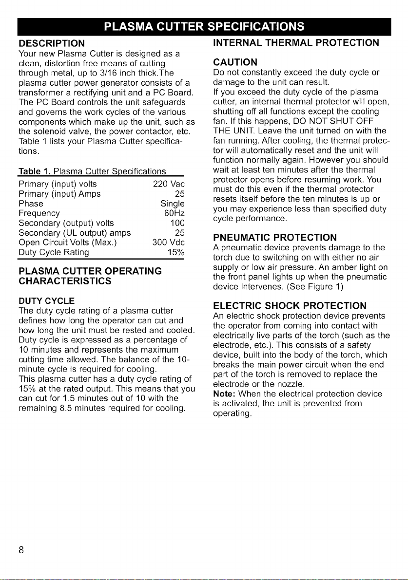
Table 1. Plasma Cutter Specifications
Primary (input) volts 220 Vac
Primary (input) Amps 25
Phase Single
Frequency 60Hz
Secondary (output) volts 100
Secondary (UL output) amps 25
Open Circuit Volts (Max.) 300 Vdc
Duty Cycle Rating 15%
PLASMA CUTTER OPERATING
CHARACTERISTICS
DUTY CYCLE
The duty cycle rating of a plasma cutter
defines how long the operator can cut and
how long the unit must be rested and cooled.
Duty cycle is expressed as a percentage of
10 minutes and represents the maximum
cutting time allowed. The balance of the 10-
minute cycle is required for cooling.
This plasma cutter has a duty cycle rating of
15% at the rated output. This means that you
can cut for 1.5 minutes out of 10 with the
remaining 8.5 minutes required for cooling.
INTERNAL THERMAL PROTECTION
CAUTION
Do not constantly exceed the duty cycle or
damage to the unit can result.
If you exceed the duty cycle of the plasma
cutter, an internal thermal protector wilt open,
shutting off all functions except the cooling
fan. If this happens, DO NOT SHUT OFF
THE UNIT. Leave the unit turned on with the
fan running. After cooling, the thermal protec-
tor wilt automatically reset and the unit will
function normally again. However you should
wait at least ten minutes after the thermal
protector opens before resuming work. You
must do this even if the thermal protector
resets itself before the ten minutes is up or
you may experience less than specified duty
cycle performance.
PNEUMATIC PROTECTION
A pneumatic device prevents damage to the
torch due to switching on with either no air
supply or low air pressure. An amber light on
the front panel lights up when the pneumatic
device intervenes. (See Figure 1)
ELECTRIC SHOCK PROTECTION
An electric shock protection device prevents
the operator from coming into contact with
electrically live parts of the torch (such as the
electrode, etc.). This consists of a safety
device, built into the body of the torch, which
breaks the main power circuit when the end
part of the torch is removed to replace the
electrode or the nozzle.
Note: When the electrical protection device
is activated, the unit is prevented from
operating.
Power Indicator
Handle, Lamp
Pneumatic
Torch
Cable
Power_
Cord
Cutting Ground
Torch Clamp
Figure 1. Model 20507 Plasma Cutter
Protection
Lamp
Thermal
Lamp
Ground
Cable
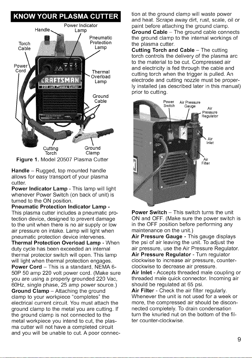
Handle - Rugged, top mounted handle
allows for easy transport of your plasma
cutter.
Power Indicator Lamp - This lamp will light
whenever Power Switch (on back of unit) is
turned to the ON position.
Pneumatic Protection Indicator Lamp -
This plasma cutter includes a pneumatic pro-
tection device, designed to prevent damage
to the unit when there is no air supply or low
air pressure on intake. Lamp wilt light when
pneumatic protection device intervenes.
Thermal Protection Overload Lamp - When
duty cycle has been exceeded an internal
thermal protector switch will open. This lamp
will light when thermal protection engages.
Power Cord - This is a standard, NEMA 6-
50P 50 amp 220 volt power cord. (Make sure
you are using a properly grounded 220 Vac,
60Hz, single phase, 25 amp power source.)
Ground Clamp -Attaching the ground
clamp to your workpiece "completes" the
electrical current circuit. You must attach the
ground clamp to the metal you are cutting. If
the ground clamp is not connected to the
metal workpiece you intend to cut, the plas-
ma cutter will not have a completed circuit
and you will be unable to cut. A poor connec-
tion at the ground clamp will waste power
and heat. Scrape away dirt, rust, scale, oil or
paint before attaching the ground clamp.
Ground Cable - The ground cable connects
the ground clamp to the internal workings of
the plasma cutter.
Cutting Torch and Cable - The cutting
torch controls the delivery of the plasma arc
to the material to be cut. Compressed air
and electricity is fed through the cable and
cutting torch when the trigger is pulled. An
electrode and cutting nozzle must be proper-
ly installed (as described later in this manual)
prior to cutting.
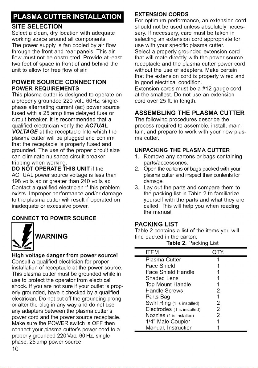
Power Air Pressure
Switch Gauge Air
Pressure
Inlet
Air
Filter
Jlator
Power Switch - This switch turns the unit
ON and OFF. (Make sure the power switch is
in the OFF position before performing any
maintenance on the unit.)
Air Pressure Gauge - This gauge displays
the psi of air leaving the unit. To adjust the
air pressure, use the Air Pressure Regulator.
Air Pressure Regulator - Turn regulator
clockwise to increase air pressure, counter-
clockwise to decrease air pressure.
Air Inlet - Accepts threaded mate coupling or
threaded mate quick connector. Incoming air
should be regulated at 65 psi.
Air Filter - Check the air filter regularly.
Whenever the unit is not used for a week or
more, the compressed air should be discon-
nected completely. To drain condensation
turn the knurled nut on the bottom of the fit-
ter counter-clockwise.
9
SITE SELECTION
Select a clean, dry location with adequate
working space around all components.
The power supply is fan cooled by air flow
through the front and rear panels. This air
flow must not be obstructed. Provide at least
two feet of space in front of and behind the
unit to allow for free flow of air.
POWER SOURCE CONNECTION
POWER REQUIREMENTS
This plasma cutter is designed to operate on
a properly grounded 220 volt, 60Hz, single-
phase alternating current (ac) power source
fused with a 25 amp time delayed fuse or
circuit breaker, It is recommended that a
qualified electrician verify the ACTUAL
VOLTAGE at the receptacle into which the
plasma cutter will be plugged and confirm
that the receptacle is properly fused and
grounded. The use of the proper circuit size
can eliminate nuisance circuit breaker
tripping when working,
DO NOT OPERATE THIS UNIT if the
ACTUAL power source voltage is tess than
198 volts ac or greater than 240 volts ac,
Contact a qualified electrician if this problem
exists, Improper performance and/or damage
to the plasma cutter wilt result if operated on
inadequate or excessive power,
CONNECT TO POWER SOURCE
WARNING
High voltage danger from power source!
Consult a qualified electrician for proper
installation of receptacle at the power source,
This plasma cutter must be grounded while in
use to protect the operator from electrical
shock. If you are not sure if your outlet is prop-
erly grounded, have it checked by a qualified
electrician, Do not cut off the grounding prong
or alter the plug in any way and do not use
any adapters between the plasma cutter's
power cord and the power source receptacle,
Make sure the POWER switch is OFF then
connect your plasma cutter's power cord to a
properly grounded 220 Vac, 60 Hz, single
phase, 25 amp power source,
10
EXTENSION CORDS
For optimum performance, an extension cord
should not be used unless absolutely neces-
sary. If necessary, care must be taken in
selecting an extension cord appropriate for
use with your specific plasma cutter.
Select a properly grounded extension cord
that will mate directly with the power source
receptacle and the plasma cutter power cord
without the use of adapters. Make certain
that the extension cord is properly wired and
in good electrical condition.
Extension cords must be a #12 gauge cord
at the smallest. Do not use an extension
cord over 25 ft. in length.
ASSEMBLING THE PLASMA CUTTER
The following procedures describe the
process required to assemble, install, main-
tain, and prepare to work with your new plas-
ma cutter.
UNPACKING THE PLASMA CUTTER
1. Remove any cartons or bags containing
parts/accessories.
2. Open the cartons or bags packed with your
plasma cutter and inspect their contentsfor
damage.
3. Lay out the parts and compare them to
the packing list in Table 2 to familiarize
yourself with the parts and what they are
called. This wilt help you when reading
the manual.
PACKING LIST
Table 2 contains a list of the items you will
find packed in the carton.
Table 2. Packing List
ITEM QTY.
Plasma Cutter 1
Face Shield 1
Face Shield Handle 1
Shaded Lens 1
Top Mount Handle 1
Handle Screws 2
Parts Bag 1
Swirl Ring (1isinstalled) 2
Electrodes (1isinstalled) 2
Nozzles (1is installed) 2
1/4" Mate Coupler 1
Manual, Instruction 1
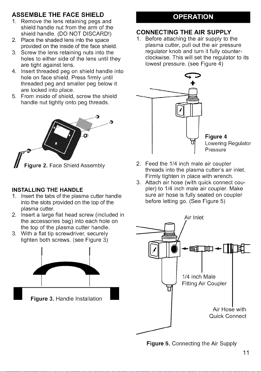
ASSEMBLE THE FACE SHIELD
1. Remove the lens retaining pegs and
shield handle nut from the arm of the
shield handle. (DO NOT DISCARD!)
2. Place the shaded lens into the space
provided on the inside of the face shield.
3. Screw the lens retaining nuts into the
holes to either side of the lens until they
are tight against lens.
4. Insert threaded peg on shield handle into
hole on face shield. Press firmly until
threaded peg and smaller peg below it
are locked into place.
5. From inside of shield, screw the shield
handle nut tightly onto peg threads.
CONNECTING THE AIR SUPPLY
1. Before attaching the air supply to the
plasma cutter, pull out the air pressure
regulator knob and turn it fully counter-
clockwise. This will set the regulator to its
lowest pressure. (see Figure 4)
÷
Figure 4
Lowering Regulator
Pressure
Figure 2. Face Shield Assembly
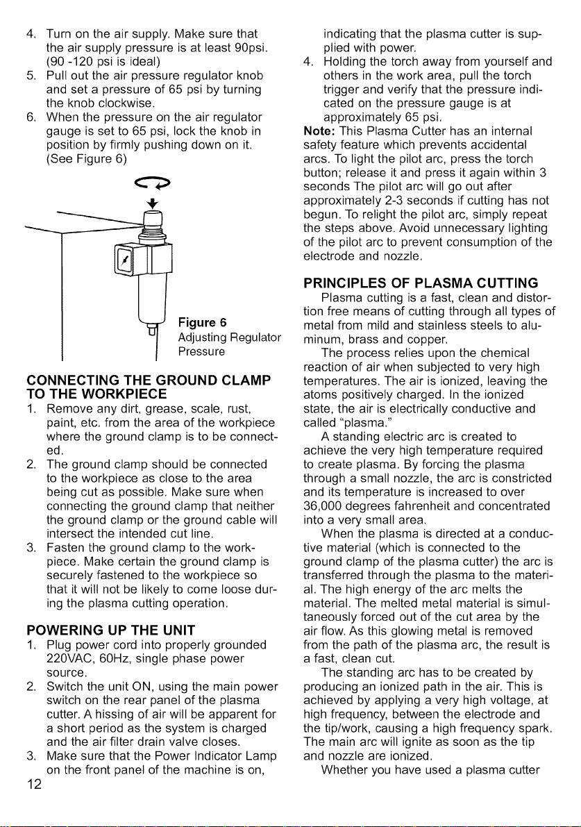
INSTALLING THE HANDLE
1. Insert the tabs of the plasma cutter handle
into the slots provided on the top of the
plasma cutter.
2. Insert a large flat head screw (included in
the accessories bag) into each hole on
the top of the plasma cutter handle.
3. With a fiat tip screwdriver, securely
tighten both screws. (see Figure 3)
Figure 3. Handle Installation
2. Feed the 1/4 inch male air coupler
threads into the plasma cutter's air inlet.
Firmly tighten in place with wrench.
3. Attach air hose (with quick connect cou-
pler) to 1/4 inch male air coupler. Make
sure air hose is fully seated on coupler
before letting go. (See Figure 5)
Air Inlet
Figure 5. Connecting the Air Supply
11
4. Turn on the air supply. Make sure that
the air supply pressure is at least 90psi.
(90 -120 psi is ideal)
5. Pull out the air pressure regulator knob
and set a pressure of 65 psi by turning
the knob clockwise.
6. When the pressure on the air regulator
gauge is set to 65 psi, lock the knob in
position by firmly pushing down on it.
(See Figure 6)
0
Figure 6
Adjusting Regulator
Pressure
CONNECTING THE GROUND CLAMP
TO THE WORKPIECE
1. Remove any dirt, grease, scale, rust,
paint, etc. from the area of the workpiece
where the ground clamp is to be connect-
ed.
2. The ground clamp should be connected
to the workpiece as close to the area
being cut as possible. Make sure when
connecting the ground clamp that neither
the ground clamp or the ground cable wilt
intersect the intended cut line.
3. Fasten the ground clamp to the work-
piece. Make certain the ground clamp is
securely fastened to the workpiece so
that it will not be likely to come loose dur-
ing the plasma cutting operation.
POWERING UP THE UNIT
1. Plug power cord into properly grounded
220VAC, 60Hz, single phase power
source.
2. Switch the unit ON, using the main power
switch on the rear panel of the plasma
cutter. A hissing of air wilt be apparent for
a short period as the system is charged
and the air filter drain valve closes.
3,
Make sure that the Power Indicator Lamp
on the front panel of the machine is on,
12
indicating that the plasma cutter is sup-
plied with power.
4. Holding the torch away from yourself and
others in the work area, pull the torch
trigger and verify that the pressure indi-
cated on the pressure gauge is at
approximately 65 psi.
Note: This Plasma Cutter has an internal
safety feature which prevents accidental
arcs. To light the pilot arc, press the torch
button; release it and press it again within 3
seconds The pilot arc will go out after
approximately 2-3 seconds if cutting has not
begun. To relight the pilot arc, simply repeat
the steps above. Avoid unnecessary lighting
of the pilot arc to prevent consumption of the
electrode and nozzle.
PRINCIPLES OF PLASMA CUTTING
Plasma cutting is a fast, clean and distor-
tion free means of cutting through all types of
metal from mild and stainless steels to alu-
minum, brass and copper.
The process relies upon the chemical
reaction of air when subjected to very high
temperatures. The air is ionized, leaving the
atoms positively charged. In the ionized
state, the air is electrically conductive and
called "plasma."
A standing electric arc is created to
achieve the very high temperature required
to create plasma. By forcing the plasma
through a small nozzle, the arc is constricted
and its temperature is increased to over
36,000 degrees fahrenheit and concentrated
into a very small area.
When the plasma is directed at a conduc-
tive material (which is connected to the
ground clamp of the plasma cutter) the arc is
transferred through the plasma to the materi-
al. The high energy of the arc melts the
material. The melted metal material is simul-
taneously forced out of the cut area by the
air flow. As this glowing metal is removed
from the path of the plasma arc, the result is
a fast, clean cut.
The standing arc has to be created by
producing an ionized path in the air. This is
achieved by applying a very high voltage, at
high frequency, between the electrode and
the tip/work, causing a high frequency spark.
The main arc will ignite as soon as the tip
and nozzle are ionized.
Whether you have used a plasma cutter
beforeornot,itisimportantthatyoubecome
familiarwithyournewplasmacutter.We
stronglyrecommendthatyoupracticewith
yournewplasmacutteronscrapmetaltrying
differentbasemetals,basemetalthicknesses,
andcuttingpositions.Bydoingthisyouwilt
gainafeelforhowchangesinthesevariables
affectthecuttingprocess.
Ofcourse,ifyouhavenotusedaplasma
cutterbefore,youwiltneedtodevelopprop-
ercuttingskillsandtechniquesaswell.
Theself-taughtoperatorlearnsthrougha
processoftrialanderror.Thebestwayto
teachyourselfhowtoplasmacutiswith
shortperiodsofpracticeatregularintervals.
Allpracticecutsshouldbedoneonscrap
metalthatcanbediscarded.Donotattempt
tomakeanycutsonvaluableequipment
untilyouhavesatisfiedyourselfthatyour
practicecutsareofgoodappearanceand
freefrommajorfaults.
ELECTRICAL
CHARGE
(-)
CUTTING TORCH
GAS -- ELECTRODE
-- SHIELDING
GAS
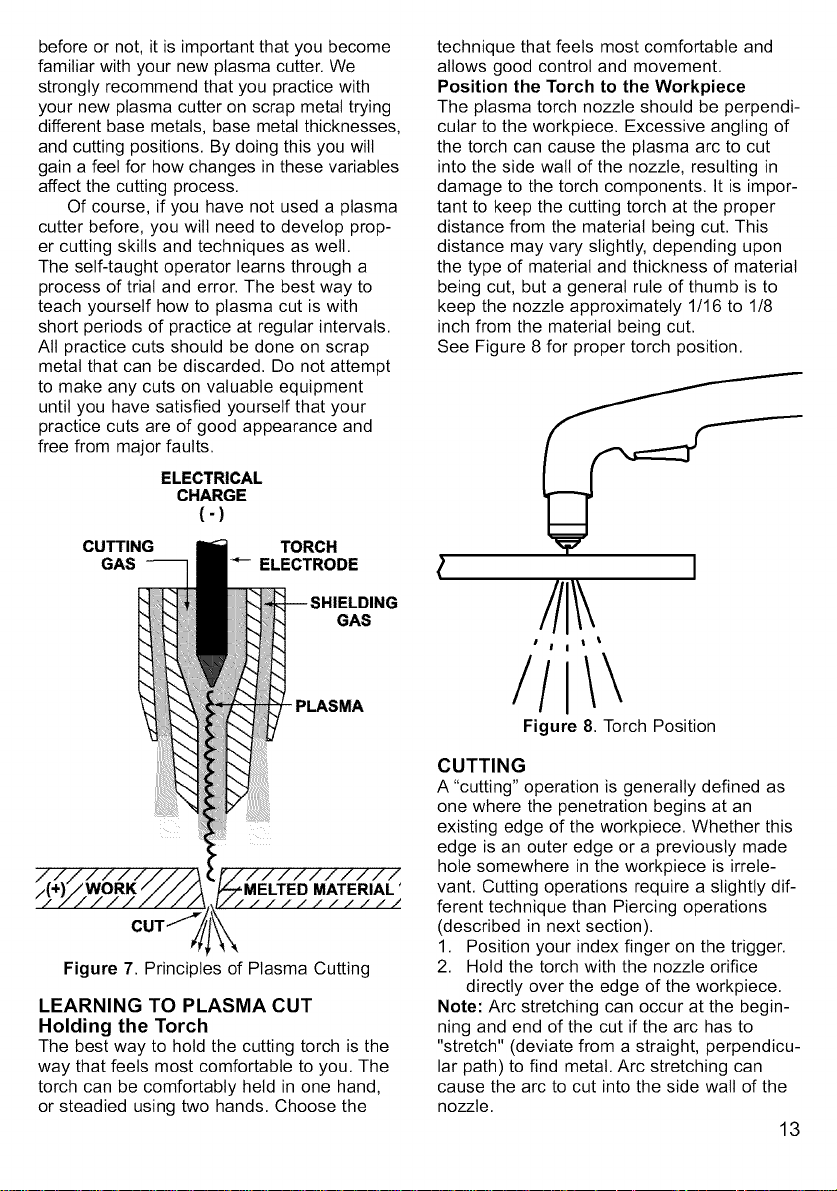
technique that feels most comfortable and
allows good control and movement.
Position the Torch to the Workpiece
The plasma torch nozzle should be perpendi-
cular to the workpiece. Excessive angling of
the torch can cause the plasma arc to cut
into the side wall of the nozzle, resulting in
damage to the torch components. It is impor-
tant to keep the cutting torch at the proper
distance from the material being cut. This
distance may vary slightly, depending upon
the type of material and thickness of material
being cut, but a general rule of thumb is to
keep the nozzle approximately 1/16 to 1/8
inch from the material being cut.
See Figure 8 for proper torch position.
I
I t
I I t
PLASMA
LEARNING TO PLASMA CUT
Holding the Torch
The best way to hold the cutting torch is the
way that feels most comfortable to you. The
torch can be comfortably held in one hand,
or steadied using two hands. Choose the
/I
Figure 8. Torch Position
CUTTING
A "cutting" operation is generally defined as
one where the penetration begins at an
existing edge of the workpiece. Whether this
edge is an outer edge or a previously made
hole somewhere in the workpiece is irrele-
vant. Cutting operations require a slightly dif-
ferent technique than Piercing operations
(described in next section).
1. Position your index finger on the trigger.
2. Hold the torch with the nozzle orifice
directly over the edge of the workpiece.
Note: Arc stretching can occur at the begin-
ning and end of the cut if the arc has to
"stretch" (deviate from a straight, perpendicu-
lar path) to find metal. Arc stretching can
cause the arc to cut into the side wall of the
nozzle.
13
 Loading...