


Owner's Manual
CRRFTSHRN®
ALL-IN-ONE
CUTTING TOOL
Model No.
183.172540
Important Safety Notice
[_, WARNING I
Always have one hand firmly
placed on the tool body while
operating, Never operate the
tool by holdingonlythe tool
handle.
• Safety Instructions
CAUTION:
Before using this Cutting
Tool, read this manual
and follow all its Safety
Rules and Operating
Instructions,
• Accessories
• Assembly
• Operation
• Maintenance
• Parts List
• Espanol
Sears, Roebuck and Co., Hoffman Estates, IL 60179 USA
Part, No, 183172540001 Rev. 0 07/21/03
Safety and Assembly Instructions
CRRFTSMRN®
FLEX SHAFT for
ALL-IN-ONE
CUTTING TOOL
Model No.
183.287660
IAWA.N,.GJ
ALWAYS WEAR EYE PROTECTION. Any power
standard Z87.1. Everyday glasses have only
impact resistant lenses. They ARE NOT safety
glasses, Safety goggles are available at most
hardware stores,
Glasses or goggles not in compliance with ANSI
Z87.1 could cause serious injury when they
break.
USE FACE OR DUST MASK along with safety
goggles if cutting or routing operation is dusty.
Make sure work area is well ventilated.
NEVER PLACE HANDS IN THE PATH OF THE
CUTTER or under the workpiece.
USE HEARING PROTECTION, particularly
during extended periods of operation,
ALWAYS RE-TIGHTEN COLLET before starting
the tool after a cutting bit or accessory has
been changed. Loose bits and accessories can
cause unexpected shifting of the tool, resulting
in loss of control and injury from the bit or
cutting tool being thrown.
NEVER TOUCH THE CUTTING BIT
IMMEDIATELY AFTER USE. The bit will be too
hot to be handled with bare hands and will burn
your fingers.
tool can throw foreign
which could cause
permanent eye damage.
ALWAYS wear safety
objects into your eyes
goggles (not glasses) that
comply with ANSI safety
ASSEMBLY INSTRUCTIONS
t.
Turn cutting toolmotor switch OFF and remove
plugfrom the power source.
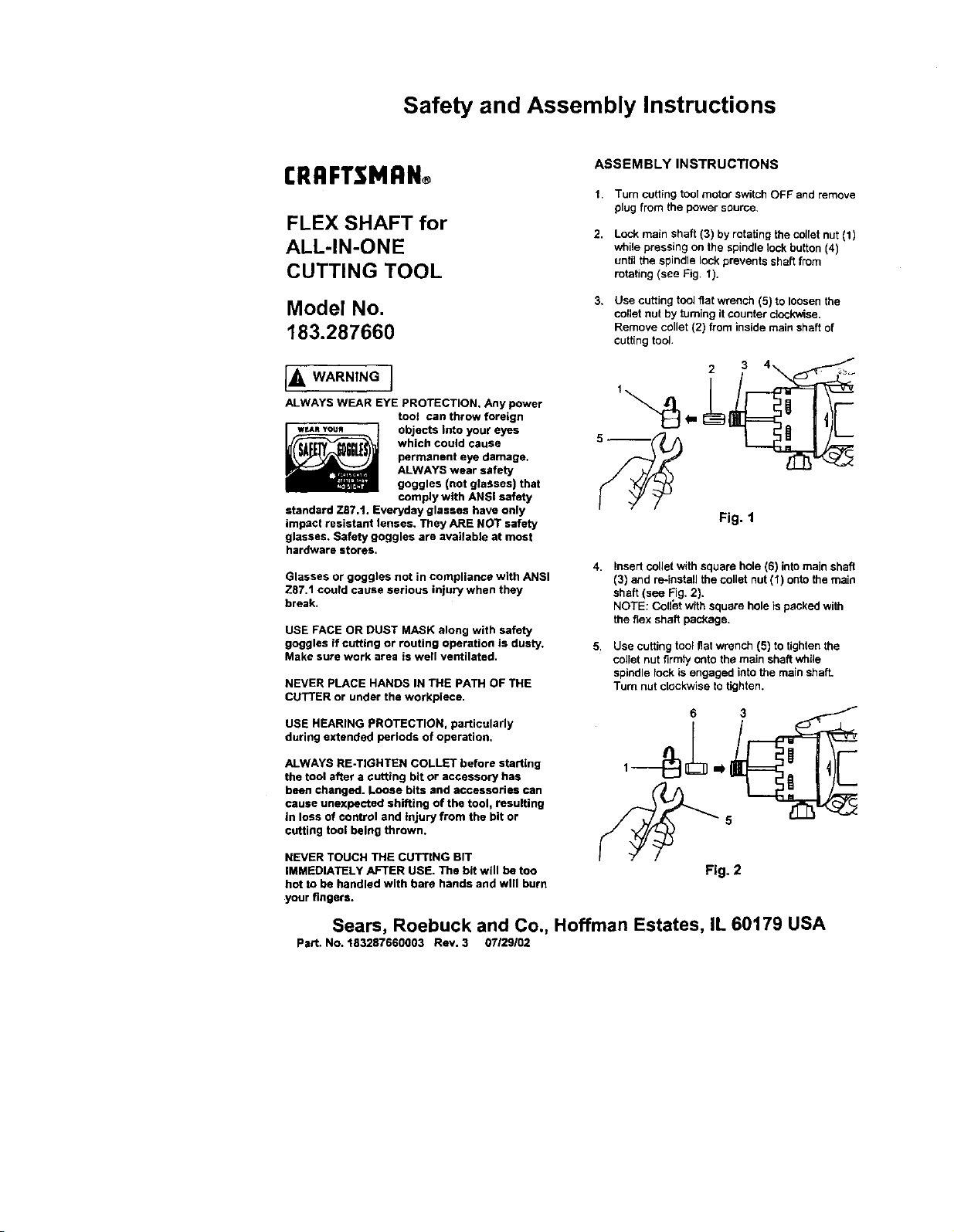
2.
Lock mainshaft (3) by rotatingthecollet nut(1)
while pressing on the spindle lockbutton (4)
untilthe spindlelock preventsshaftfrom
rotating (see Fig 1).
3.
Use cutting toolfiat wrench (5) to loosenthe
collet nut by turningit counter clockwise.
Remove collet(2) from insidemain shaft of
cutting tool.
2 3
Fig. 1
4. Insert collet withsquare hole (6) intomain shaft
(3) and re-installthe collet nut(1) onto the main
shaft(see Fig. 2).
NOTE: Coll_t with square hole ispackedwith
the flex shaft package.
5. Use cutting tool fiatwrench (5) to tightenthe
colletnut firmty onto the main shaftwhile
spindle lock is engaged into the main shaft,
Turn nut clockwise to tighten.
Fig. 2
Sears, Roebuck and Co., Hoffman Estates, IL 60179 USA
Part. No. 183287660003 Rev. 3 07129102
SECTION PAGE
Warranty........................................ 2
ProductSpecifications...................... 2
PowerToolSafety ............................ 3
CuttingToct&AccessorySafety ......... 4
ElectricalRequirement&Safety .......... 5
CuttingTootSymbols........................ 6
SECTION PAGE
ACCSS_ .................................... 7
Carton Contents .............................. 7 - 8
Know Your Cutting Toct .................... 9 - 10
Assembly & Operation ...................... 11 - 23
Maintenance ................................... 24
Repair Parts ................................... 25 - 36
FULL ONE YEAR WARRANTY
If this Cutting Tool fails due to a defect in material or workmanship within one year of date of
purchase, Sears will at its optionrepair or replace itfree of charge.
Return this Cutting Tool to a Sears Service Center for repair, or to place of purchase for
replacement.
This warranty gives you specific legal rights, and you may also have other dghts which may vary
from state to state.
Sears, Roebuck and Co., Dept. 817 WA, Hoffman Estates, IL 60179
[A WARNINGJ
Some dust created by power sanding, sawing, grinding, drilling and other construction activities contains
chemicals known (to the State of California) to cause cancer, birth defects or other reproductive harm. Some
examples of these chemicals are:
• Lead from lead-based paints
• Crystalline silica from bricks, cement and other masonry products
• Arsenic and chromium from chemically treated lumber
Your risk from these exposures varies, depending on how often you do this type of work. To reduce your
exposure to these chemicals, work in a well ventilated area and work with approved safety equipment such as
those dust masks that are specially designed to filter out microscopic particles,
Motor Rating ...................... 120 V, 60 Hz, AC
Amperes ........................... 5.0 A
Two Speeds (no load) ......... 20,000 & 30,000 RPM
Motor Horsepower ...... 3/4HP (Maximum Developed)
Weight ..................... 3 lb. 12 oz, (1.7 kg)
Maximum Disc SiZe .... 4" Diameter
J_ WARNING I
To avoid electrical hazards, fire hazards or damage to the tool, use proper circuit protection.
This power tool is wired at the factory for 110-120 V operation. It must be connected to a 110-120 V 115 A time
delayed fuse or circuit breaker. To avoid shock or fire, replace power cord Immediately if it is worn, cut or
damaged in any way.
Before using your cutting tool, it Is critical that you read and understand these safety rules, Failure to follow
these rules could result in serious Injury to you or damage to the cutting tool.
2
Safety and Assembly Instructions
ASSEMBLY INSTRUCTIONS - cont'd
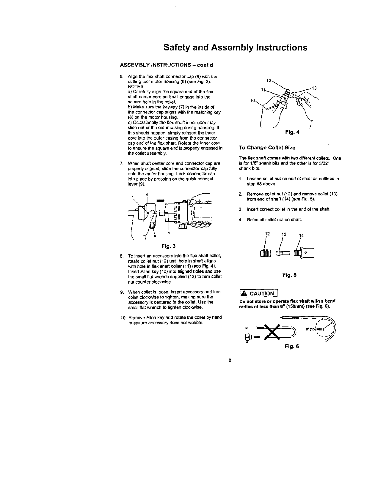
6. Align the flex shaft connector cap (6) wfth the
cutting tool motor housing (8) (see Fig. 3).
NOTES:
a) Carefully align the square endof the flex
shaft center core so it will engage into the
square hole in the collet.
b) Make sure the keyway (7) in the inside of
the connector cap alignswith the matching key
(8) on the motor housing.
c) Oocasionally theflex shaft inner core may
slide out of the outer casing durthg handling. If
this should happen, simply reinsert the inner
coreinto the outer casing from the connector
cap end of the flex shaft. Rotate the ironercore
to ensure the square end is properlyengaged in
the collet assembly.
7. When shaft center coreand connector cap are
properly aligned,slidethe connectorcap fully
ontothe motor housing. Lock connectorcap
intoplace by pressing on the quick connect
lever (g).
9
Fig. 3
8. To insert an accessory intothe flex shaft collet,
rotate collet nut (12) untilhole in shaft aligns
with hole in flexshaft collar (11) (see Fig. 4).
insert Allen key (10) intoaligned holes and use
the small fiat wrench supplied (13) to turn toilet
nutcounter clockwise.
9. When collet is loose, insert accessory and turn
col)atclockwise to tighten, making sure the
accessoryis centered in the collet, Use the
smallfiat wrench to tighten clockwise.
10. Remove Allen key and rotate the ¢otlet by hand
to ensure accessory does notwobble.
t2
11 13
Fig. 4
To Change Cotlet Size
The flex shaft comes with two differentcollets+ One
is for 1/8"shank bits and the otheris for 3/32"
shank bits.
1. Loosen colletnut on end of shaftas outlinedin
step #8 above.
2. Remove collet nut (12) and remove collet(13)
from end of shaft(14) (see Fig. 5).
3. Insert correct collet in the end of the shaft.
4. Reinstall collet nut on shaft.
12 13 14
,o
Fig. 5
Ih,CAU ONI
Do not store or operate flex shaft with a bend
radius of less than 6" (150ram) (see Fig. 6).
Fig. 6
[_ WARNING--]
Before using your cutting tool, it is critical
that you read and understand these safety
rules. Failure to follow these rules could
result in serious injury to you or damage to
the cutting tool
Good safety practices are a combination of common
sense, staying alert and understanding how to use your
power tool. To avoid mistakes that couldcause serious
thjuty, do not pJugin your cuing tooJuntil you have read
and understoo_ the follOWing safety rules:
READ and become familiar with thisentire Owner's
Manual. LEARN the tool's applications, limitationsand
possible hazards.
t-,_ WARNING_
LOOkfor this symbo_that identifies important safety
precautions. Itmeans CAUTIONI BECOME ALERTt,
YOUR SAFETY IS INVOLVEDI
GENERAL SAFETY RULES
KEEP GUARDS IN PLACE and in working order.
ALWAYS WEAR EYE PROTECTION. Any powertool
can throw foreign objects into your eyes
damage. ALWAYS wear safety goggles
which cOUldcause permanent eye
(not glasses) that comply with ANSI
glasses have only impactresistant lenses. *l_heyARE
NOT safety glasses. Safety goggles are available at
Sears.
safety standard Z87.1. Everyday
IA,WARN'NGI
Glasses or goggles not in compliance with ANSI
Z87,1 could cause serious injury when they break.
WORK AREA
Keep your work area clean and well lit. Cluttered
benches and dark areas invite accidents.
Do not operate power tools in explosive
atmospheres, such as in the presence of flammable
liquids, gasses or dust. Power toolscreate sparks
which may lgnttethe dust or fumes.
Keep bystanders, children and visitors away while
operating the tool. Distractions can cause you to lose
control
PERSONAL SAFETY
Stay alert, watch what you are doing and use
common sense when operating a power tool. Do not
use the toot while tired or under the influence of
drugs, alcohol or medication. A moment of inattention
while operatingpower tools mey result in serious
person_ injury.
SAVE THESE INSTRUCTIONS FOR REFERENCE
Dress properly. Do not wear loose clothing or jewelry
Contain long hair. Keep your hair, clothing and
gloves away from moving parts. Loose clothing.
jewelry or long hair can be caught In moving parts.
Avoid accidental starting. Re sure switch is OFF
before plugging in. Carting too_swith yourfinger on
the switch or plugging in tools that have the switch ON
invites accidents.
Remove adjusting keys or wrenches before turning
the tool ON. A wrench or key that is left attached to a
rotating part of the tool may result in personal injury
Do not overreach. Keep proper footing and balance
at all times. Proper footing and balance enables better
control of the toct in unexpected situations.
Use safety equipment. Always wear eye protection.
Dust mask, non-skid safety shoes, hard hat or
hearing protection must be used for appropriate
conditions.
TOOL USE AND CARE
Use clamps or other practical way to secure and
support the workpiece to a stable platform. Holding
the work by hand or against your body is unstable and
may lead toJossof control.
Do not force the tool Uae the correct tool for your
application. The correct tooIwilldo the job better and
safer at the rate for which it is designed.
Do not use the tool it the switch does not turn it ON
or OFF. Any tool that cannot be controlledwith the
switch is dangerous and must be repaired.
Disconnect the plug from the power source before
making any adjustments, changing accessories or
storing the tool. Such preventive safety measures
reduce the risk of starting the tool accidentally.
Store idfa toots out of reach of children and other
untrained persons. Tools are dangerous in the hands of
untrained users.
Maintain tools with care, Keep cutting tools sharp
and clean. Preper/y maintained cuttingtools with sharp
cuttingedges are less likely to bind and are easier to
control.
Check for misalignment or binding of moving parts,
breakage of parts and any other condition that may
affect the tool's operation. If damaged, have the tool
serviced before using. Many accidents are caused by
poorly maintained too!s.
Use only accessories that are recommended by the
manufacturer for your model Accessories that maybe
suitable for one toolmay become hazardous when used
on another tool
SERVICE
Tool service must be performed only by qualified
personnel Service or maintenance performed by
unqualified personnel could result in risk of injury.
When servicing a tool, use only identical
replacement parts. Follow instructions in the
Maintenance section of this manual. Use of
unauthorized parts or failure to follow Maintenance
instructions may create a dsk of electric shock or injury.
ANGLE GRINDER ATTACHMENT SAFETY
L='wAr.J.GI
Always wear safety goggles with side shields or a
face mask when using the angle grinder attachment.
High speed grinding and sanding will throw hot
sparks and dust particles that could cause serious
injury to your eyes.
Always wear hearing protection when using the angle
grinder attachment.
SPECIFIC SAFETY RULES
Hold tool by insulated gripping surfaces when
performing an operation where the cutting tool may
contact hidden wiring or its own cord. Contact with a
"live" wire will make exposed metal parts of the tool "live"
and shock the operator.
Always make sure the work surface is free from nails
and other foreign objects, Cutting into a nail can cause
the bit and the tool to jump and damage t_e bit.
Never hold the workpiece in one hand and the tool in
the other hand when in use. Never place the hands
near or below the cutting surface. Clamping the
mateda[ and guiding the tool with both hands is much
safer,
Never lay workpiece on hard surfaces like concrete,
stone, etc. Protruding cutting bit may cause tool tojump.
Always wear safety goggles, hearing protection and
dust mask. Use only in well ventilated area. Using
personal safety devices and working in a safe
environment reduces risk of injury.
After changing the bits or making adjustments, make
sure the collet nut end any other adjustment devices
are securely tightened. Loose adjustment devices will
be violently thrown.
Never use dull or damaged bits. Sharp bits must be
handled with care, Damaged bits can snap during use.
Dull bits require more force to push the tool, possibly
causing the bit to break.
Never touch the bit during or Immediately after use.
After use the bit is too hot to be touched by hare hands.
Always use appropriate dust mask when using the
angle grinder attachment.
Use ONLY grinding wheels and sanding discs rated
for speeds greater than 18,000 RPM, as the angle
grinder attachment runs st speeds from 12,000 -
18,000 RPM.
Inspect the grinding wheel before each use to make
sure it is tightly fastened and free from cracks or any
other damages.
Rotate the guard to a position where it will protect the
operator from sparks and dust. The guard should be
positioned immediately in front of the side handle to
protect the operator's hand.
Do not over tighten the nut holding the grinding
wheel in place. Excessive tightening may cause the
grinding wheel to crack and possibly shatter dudng
operation.
Do not clamp the angle grinder attachment in a vice
or usa as a fixed grinder.
Hold the angle grinder attachment securely with two
hands at ell times while it is running.
Never turn the motor switch ON with the grinding
wheel or sanding disc touching the work surface.
FLEXIBLE SHAFT SAFETY
When using the flexible shaft accessory, always
hang the motor unit on a hook using the hanging loop
at the top of the motor housing.
Always use safety glasses, hearing protection and a
dust mask.
Never hold the workplace with your hand while using
a cutting biL Clamp the wofkpiece in a vice or to a
workbench to permit using two hands on the flex shaft.
Never place hands in the path of the cutter or under
the wod(piece.
Do not store or operate the flex shaft with a bend
radius of less than g" (150 ram).
SAVE THESEINSTRUCTIONS FOR REFERENCE
4
IZolUl;pie;il_ F;ll IIP'_,IIIfe__
This cutting tool is double insulated to protect you from
el_l shock,
WARNIN N
Double Insulated tools are equipped with a polarized
plug (one blade is wider than the other). This plug
will fit Into a polarized outlet only one way. If the plug
does not fit fully into the outlet, reverse the plug, If it
still does not fit, contact a qualified electrician to
install a polarized outleL Do not alter the plug In any
way. Double insulation eliminates the need for the three
wire grounded power cord and grounded power supply
system.
Avoid body contact with grounded surfaces such as
pipes, radiators, ranges and refrigerators. There is an
increased risk of electric shock if your body is grounded.
Do not expose power tools to rain or wet conditions,
Water entering a power tool will increase the risk of
electric shock.
Do not abuse the cord. Never use the cord to carry
the tool or pull the plug from the outlet. Keep cord
away from heat, oil, sharp edges and moving parts.
Replace damaged cords immediately. Damaged cords
increase the dsk of electric shock.
When operating a power tool outdoors, use an
outdoor extension cord marked '_N-A" or "W". These
cords are rated for outdoor use arm reduce the risk of
• e]ecfric shock,
Make sure your extension cord is in good condition.
When using an extension cord, be sure to use one heavy
enough to carry the current the tool will draw. An
undersized cord will cause a drop in line voltage resulting
in loss of power and overheating, The table below shows
the correct size to use according to cord length and
nameplate ampere rating. If in doubt, use the next
heavier gauge. The smaller the gauge number the
heavier the cord.
Be sure your extension cord is propedy wired and in
good condition. Always replace e damaged extension
cord or have it repaired by a qualified electrician before
using it. Protect your extension cord from sharp objects,
excessive heat and damp or wet areas.
Use a separate electrical circuit for your power tools.
This circuit must not be loss than 14 gauge wir_nd
should be protected with either a 15 Ampere time delay
fuse or circuit breaker. Before connecting the power tool
to the power source, make sure the switch is in the OFF
position and the power source is the same as indicated
on the nameplate. Running at lower voltage will damage
the motor.
IA WARNING I
Repair or replace damaged or worn extensioncords
immediately.
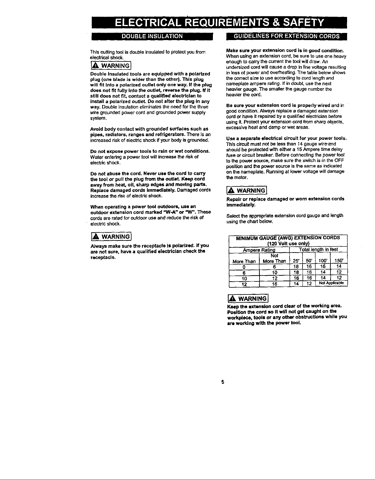
Select the appropriate extension cord gauge and length
using the chart below.
I_ WARNING I
Always make sure the receptacle is polarized. If you
are not sure, have a qualified electrician check the
receptacle.
MINIMUM GAUGE (AWG) EXTENSION CORDS
(120 Volt use only)
Ampere Rating Total length in feet
Not IMore Than More Than 25' 50' 100' 150'
O 6 18 16 I 16 14
6 10 18 16 I 14 12
t0 12 I 16 16 14 12
t2 16 I,_14 12 NotApplicable
[,_. WARNING J
Keep the extension cord clear of the working area,
Position the cord so it will not get caught on the
workplece, tools or any other obstructions while you
ere worklng with the power tool.

IA WARNING I
Some of the following symbols may be used on
your tool. Please study them and learn their
meaning. Proper interpretation of these symbols
will allow you to operate the tool better and safer.
V
volts
A
amperes
Hz
W
kW
#F
kg
N/cm z
Pa
min
hertz
watt
kilowatts
micro farads
I
liters
kilograms
newtons per square centimeter
pascals
h
hours
minutes
seconds
S
altemating current
®
LISTED
no
[]
z_
iA
@
,..Imin
o
0
This symbol designates that this
tool is listed with U.S.
requirements by Underwriters
Laboratories.
three-phase alternating current
three-phase alternating current with
neutral
direct current
no load speed
alternating or direct current
class II construction
splash proof construction
watertight construction
protective earthing at earthing terminal,
Class I tools
revolutions or reciprocations per minute
Diameter
Off position
Arrow
Warning symbol
AVAILABLEACCESSORIES
IA WARNING J
Use only accessories recommended for this cutting
tool. Follow instructions that accompany
accessories. Use of improper accessortes may cause
injury to the operator or damage to the Cutting Tool.
Visit your Sears Hardware Department or see the
Sears Power and Hand Tool Catalog for an assortment
of accessories recommended for use with this cutting tool:
_/_"Cutting Bits
_la"& 3132"Hobby Rotary Tool Accessories
_, Cutters
> Polishers
Sanders
> Grinders
Most '/4"Shank Router Bits
3 '/="Grinding Disks
4" Sanding Disks
)f:_;_l(I]_l [e[o]ll i :1_11[,;
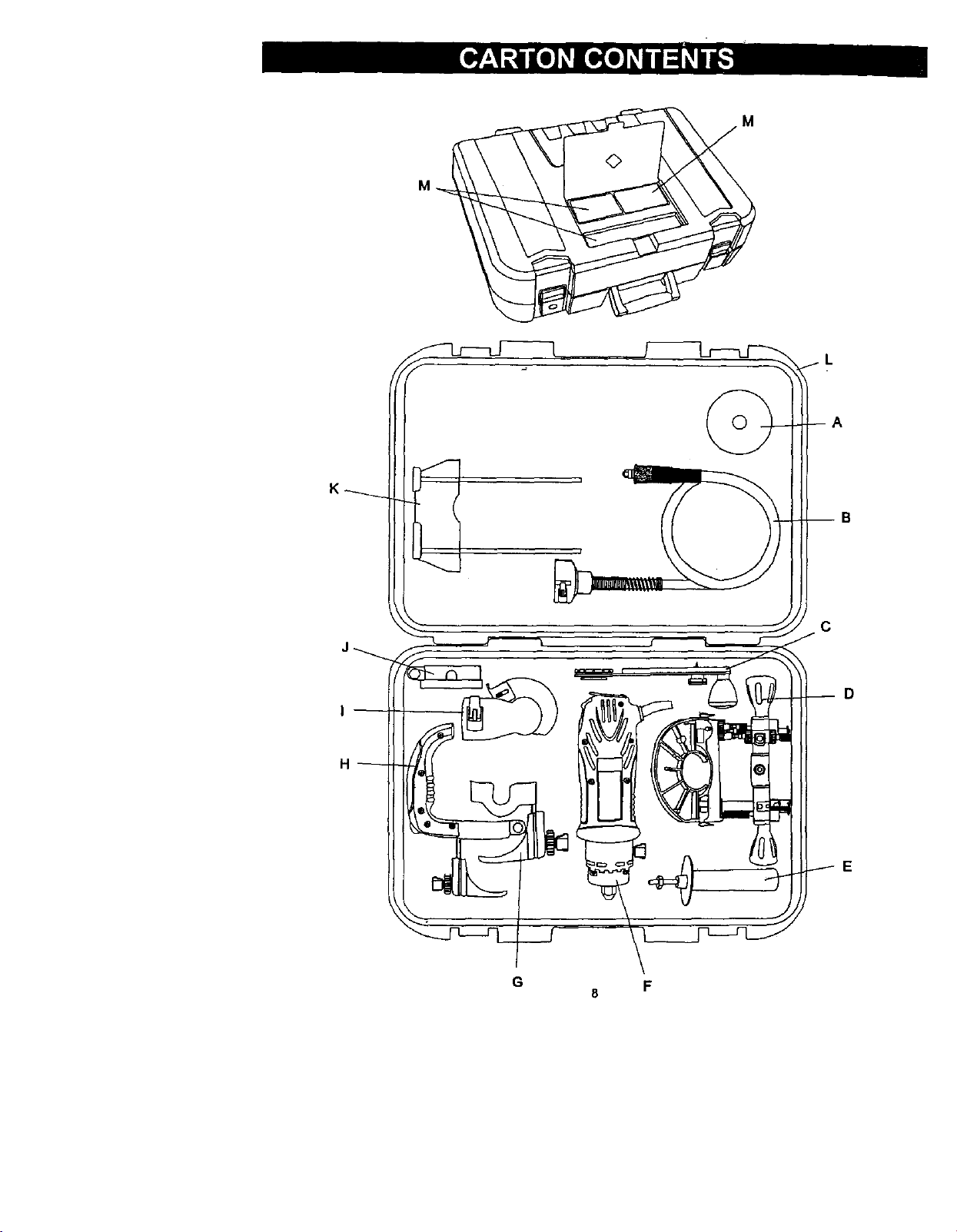
UNPACKING AND CHECKING CARTON CONTENTS
IA WARNINGJ
If any part is missing or damaged, de not plug the
Cutting Tool into the power aource until the missing
or damaged part is replaced and assembly is
complete.
Carafully unpack the Cutting Tool and all its components.
Compare against the =Cutting Tool Components" chart.
NOTE: See Page 8 & 9 for illustration of components.
J_. WARNING I
To avoid fire or toxic reaction, never use gasoline,
naphtha, acetone, lacquer thinner or similar highly
volatile solvents to clean the cutting tool.
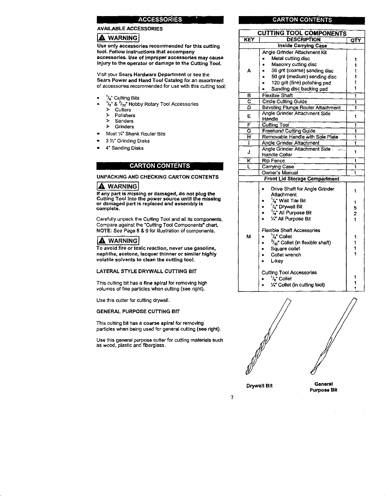
LATERAL STYLE DRYWALL CUTTING BIT
This cutting bit has a fine spiral for removing high
volumes of fine particles when cutting (see right).
CUTTING TOOL COMPONENTS
KEY J DESCRIPTION I QI;Y
A 36 grit (coarse} sanding disc 1
B Flexible Shaft 1
C Circle Cutting Guide 1
D Beveling Plunge Router Attachment 1
E Angle Grinder Attachment Side 1
F Cuffing Tool
G Freehand Cutting Guide 1
H Removable Handle with Sole Plate t
t Angle Gdnder Attachment 1
j Angle Grinder Attachment Side • "" t
K Rip Fence t
L Carr_ng Case I
M
Inside Carrying Case
Angle Grinder Attachment Kit
Metal cutting disc 1
Masonry cutting disc 1
50 grit (medium) sanding disc 1
120 grit (fine) polishing pad 1
Sanding disc backing pad 1
Hendle
Handle Collar
Owner's Manual t
Front Lid Storage Compartment
Drive Shaft for Angle Grinder 1
Attachment
_/8"Wall Tile Bit 1
1/8"Drywall Bit 5
lie" All Purpose Bit 2
¼" All Purpose Bit 1
Flexible Shaft Accessories
l/e" Collet 1
3/==.Collet (in flexible shaft) 1
Square coilet 1
Coflet wrench 1
• L-key
Cutting Tool Accessories
_/a"Collet 1
¼" Collet (in cutting tool) 1
1
Use this cutter for cutting drywall
GENERAL PURPOSE CUTTING BIT
Thiscutting bithas acoarse spiral for removing
particles when beingusedfor generalcutting(see right).
Use this general purpose cutter for cutting materials such
as wood, plastic and fiberglass,
Drywall Bit General
Purpose Sit
7
M
K_
D
H
G F;
8
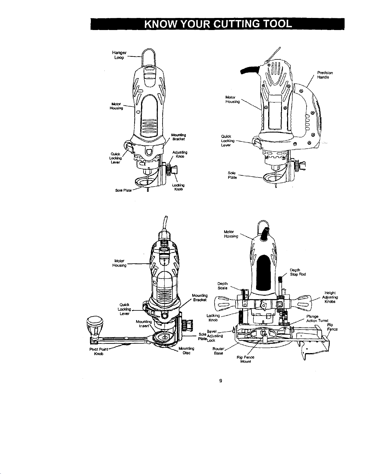
Loop
H_ng C:) <
I_ver
Adjusting
KnOb
Motor
Housir
Quick
Lod_ng
Le_r
,So4e
Prate
precision
Handle
Knob
Motor
Housing
Quick
Lever
Mounting
OLSC
Mounting
Sole Adjusting
Pla_eLoc_
Knob
Base
DepUl
SCale
Motor
Housir
Rip Fence
Mount
Depth
StopRod
PSunge
Action Turret
Height
Knobs
Rip
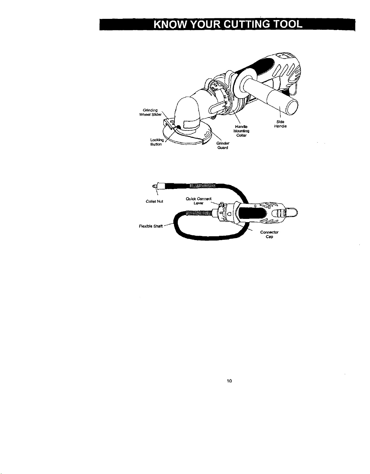
Grinding
Lockln
Button
Handle
Mounting
Colla¢
Cc41etNut Lever
Qulc_Connect
Connector
Cap
lO