

Page 1
Owner’s Manual
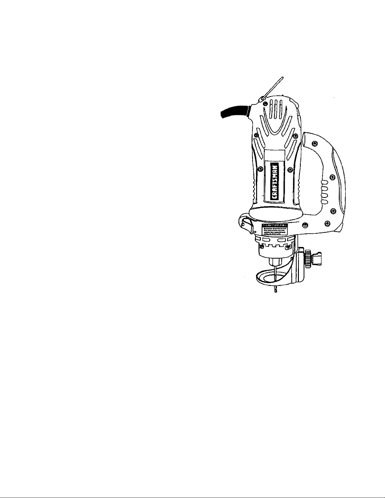
CRAFTSMAN
ALL-IN-ONE
CUTTING TOOL
Model No.
183.172530
Important Safety Notice
A WARNING
Always have one hand firmly
placed on the tool body
while operating. Never
operate the tool by holding
only the tool handle.
CAUTION:
Before using this Cutting
Tooi, read this manual and
follow all its Safety Rules
and Operating
instmctions.
• Accessories
• Assembiy
• Operation
• Maintenance
• Parts List
• Espanol
Sears, Roebuck and Co., Hoffman Estates, iL 60179 USA
Part. No. 183172530001 Rev.O 12/25/02
•* Safety Instructions
Page 2

TABLE OF CONTENTS
SECTION
Warranty
Product Specifications
Power Tool Safety
Cutting Totri Safety
Electrical Requirements & Safety
Accessories
.........................................................
...............................
........................................
......................................
..................................................
.............
PAGE SECTION
. 2
.
. 2
. 3
. 4
.
. 5
. 6
Carton Contents
Know Your Cutting Tool
Assembly & Operation
Maintenance............................................
Repair Parts............................................
Parts & Service Availabifity
....................................
......................
........................
................
.
.......
.
.
.......
PAGE
8
18
WARRANTY
FULL ONE YEAR WARRANTY
If this Cutting Tool fails due to a defect in material or workmanship within one year of date of
purchase, Sears will at its option repair or replace it free of charge.
Return this Cutting Tool to a Sears Service Center for repair, or to place of purchase for
replacement.
This warranty gives you specific legal rights, and you may also have other rights which may vary
from state to state.
Sears, Roebuck and Co., Dept. 817 WA, Hoffman Estates, IL 60179
A WARNING
Some dust created by power sanding, sawing, grinding, drilling and other construction activities contains
chemicals known (to the State of California) to cause cancer, birth defects or other reproductive harm. Some
examples of these chemicals are;
• Lead from lead-based paints
■ Crystalline silica from bricks, cement and other masonry products
• Arsenic and chromium from chemically treated lumber
Your risk from friese exposures varies, depending on how often you do this type of work. To reduce your exposun
to these chemicals, work in a well ventilated area and work with approved safety equipment such as those dust
masks that are specially designed to filter out microscopic particles.
PRODUCT SPECIFICATIONS
Motor Rating
Amperes
2 Speeds (no load)
.................................
........................................
......................
12CA/. 60Hz, AC
5.0 Amperes
20000 & 30000 RPM
Motor Horsepower
Weight
................................
..........
% HP (Maximum Developed)
1-7 kg
A WARNING
To avoid electrical hazards, fire hazards or damage to the cutting tool, use proper circuit protection.
This cutting tool is wired at the frictory for 110-120 Volt operation. It must be connected to a 110-120 Volt /15
Ampere time delay fuse or circuit breaker. To avoid shock or fire, replace power cord immediately if it is worn, cut
or damaged in any way.
Before using your cutting tool, it is critical that you read and understand these safety rules. Failure to follow these
rules could result in serious Injury to you or damage to the cutting tool.
Page 3

POWER TOOL SAFETY
▲ WARNING
Before using your cutting tool, it is critical that you read and understand these safety rules. Failure to follow these rules could result in serious injury to you or damage to the cutting tool.
Good safety practices are a combination of common
sense, staying alert and understanding how to use your
power tool. To avoid mistakes that could cause serious
injury, do not plug in your cutting tool until you have read
and understood the following safety rules:
1.
READ and become familiar with this entire Owner’s
Manual. LEARN the tool’s applications, limitations and
possible hazards.
2.
A WARNING
Look for this symbol that identifies important safety
precautions. It means CAUTIONI BECOME ALERTI
YOUR SAFETY IS INVOLVEDI
3. KEEP GUARDS IN PLACE and in working order.
4. OO NOT USE IN A DANGEROUS ENVIRONMENT
such as damp or wet locations or exposure to rain.
Keep woik area well lighted.
5. DO NOT use power tods in the presence of
flammable liquids or gases.
6. KEEP WORK AREA CLEAN. Cluttered areas and
workbenches invite accidents.
7. KEEP CHILDREN AWAY. All visitors should be kept
at a safe distance from the work area.
8. DO NOT FORCE THE TOOL. It will do the job better
and safer at the rate for which it was designed.
9. USE THE RIGHT TOOL. Do not force the tool or
attachment to do a job for which it is not designed.
10. WEAR PROPER APPAREL DO NOT wear loose
Clothing, gloves, neckties, rings, bracelets or other
jewelry that may get caught in moving parts. Non-slip
footwear is recommended. Wear protective hair
covering to contain long hair.
11. WEAR A FACE MASK OR DUST MASK. Sawing,
cutting, drilling and sanding operations produce
hazardous dust.
12. DISCONNECT TOOLS FROM THE POWER
SOURCE before servicing and when changing
accessories such as blades, bits, cutters, etc.
13. REDUCE THE RISK OF UNINTENHONM.
STARTING. Make sure the svritch is in the “OFP
position before plugging into the power source.
14. USE ONLY RECOMMENDED ACCESSORIES.
Consult tite Ovmer's Manual for recommended
accessories. The use of improper accessories may
cause injury to you or damage to tiie tool.
15. REMOVE ADJUSTING KEYS AND WRENCHES.
Form the habit of checking to see that keys and
adjusting wrenches are removed from the tool before
turning "ON".
16. NEVER LEAVE TOOL RUNNING UNATTENDED.
TURN THE POWER “OFF", Do not leave the tool
before it comes to a complete slop.
17. NEVER STAND ON TOOL. Serious injury could occur
if the tool is tipped or if the cutting tool is
unintentionally contacted.
18. DO NOT OVER REACH. Keep proper footing and
balance at all times.
19. MAINTAIN TOOLS WITH CARE. Keep tools sharp
and dean for most efficient and safest performance.
Follow instructions for lubricating and changing
accessories.
20. CHECK FOR DAMAGED PARTS. Before further use
of the tool, a guard or other part that is damaged
should be carefully checked to en^re it will operate
' property and perform its intended function. Check for
alignment of moving parts, binding of moving parts,
mounting and any other conditions that may affect its
safe operation, A guard or other part that is damaged
should be properly repaired or replaced.
21. MAKE WORKSHOP CHILD PROOF wth padlocks,
master switches or by removing starter ke]^.
22. DO NOT operate the tool If you are under the
influence of any drugs, alcohot or medication that
could impair your abili^ to use the tool safely.
23. USE OUST COLLECTION SYSTEM wherever
possible. Dust generated from certain materials can
be hazardous to your health artd In some cases, a fire
hazard. Always operate the power tod in a well
ventilated area with adequate dust removal.
ALWAYS WEAR EYE PROTECTION. Any power tool
24,
ANSI safety standard Z87.1. Everyday glasses have
only impact resistant lenses. They ARE NOT safety
glasses. Safety goggles are available at Sears.
can throw foreign objects into
your eyes which could cause
permanent eye damage.
alw ays wear safety goggles
(not glasses) that comply with
A WARNING
Glasses or goggles not In compliance with ANSI
Z87.1 could cause serious Injury when they break.
SAVE THESE INSTRUCTIONS FOR REFERENCE
Page 4

CUTTING TOOL SAFETY
A WARNING
For your safety, do not plug in your cutting tool or try
to use any accessory until It is completely assembled
and installed according to these instructions, and
until you have read and understood this Owner’s
Manual.
11. NEVER HOLD THE WORKPIECE (N ONE HAND
while operating the tool with the other hand.
12. NEVER PLACE HANDS IN THE PATH OF THE
CUTTER AND UNDER THE WORKPIECE.
Failure to follow these safety rules will result in risk of
serious Injury. ’
1. WEAR EYE PROTECTION. This high speed tool will
throw particles from the workpiece during operation.
Make sure safety glasses have side shields.
2. USE FACE OR DUST MASK along with safety
goggles if cutting or routing (deration is dusty. Make
sure work area is well ventilated.
3. USE HEARING PROTECTION, particularly during
extended periods of operation.
4. NEVER USE DULL OR DAMAGED BITS. Damaged
bits can break without warning. Dull bits may overload
the motor, cut slowly and are difficult to control. They
will also overheat and possibly break.
5. ALWAYS MAKE SURE THE WORKPIECE IS FREE
OF NAILS AND OTHER FOREIGN OBJECTS. If the
bit strikes a nail It will jump sideways and possibly
break.
6. DO NOT USE THIS TOOL FOR DRILUNG HOLES.
It is NOT intended to be used as a drill.
7. ALLOW CLE/UIANCE UNDER WORKPIECE for bit
to travel. Never place workpiece on hard surfaces
such as concrete etc. The bit may jump or break when
contacting a surface other than the one being cut.
8. ALWAYS SET THE DEPTH GUIDE TO THE
APPROPRIATE DEPTH. Use tool vrith the depth
guide flat against the work surface for better control of
the tool.
9. NEVER use THE TOOL WITHOUT THE SOLE
PLATE, PRECISION HANDLE OR ROUTER BASE
attached and appropriately adjusted.
10. ALWAYS CLAMP WORKPIECE TO HOLD IT
STEADY WHEN CUTTING. This will free both hands
for operating the tool.
13. NEVER START THE TOOL WHEN THE BIT IS
TOUCHING THE WORKPIECE. The bit may catch
the workpiece causing loss of control.
14. ALWAYS HOLD THE TOOL WITH TWO HANDS
DURING START-UP AND OPERATION. When
starting, motor torque will cause the tool to twist,
15. TURN OFF ALL CIRCUIT BREAKERS AND
REMOVE ALL FUSES in the work area when cutting
into walls or blind areas.
16. ALWAYS HOLD THE TOOL BY THE INSULATED
GRIPPING SURFACES ON THE BODY OF THE
TOOL where there is any possibility of the cutting bit
contacting hidden electrical wires or the cord of the
tool. Contact with "live” virires will make exposed metal
parts of the tool "live” causing an electrical shock to
the operator.
17. WHEN CUTTING DRYWALL ELECTRICAL OUTLET
OPENINGS using the outlet as a guide, always cut in
a counter clockwise direclloo. The natural tendency of
the tool to pull to the left will cause a "hugging” action
toward the outlet box, resulting in a neater cut.
18. NEVER LAY THE TOOL DOWN UNTIL THE
CUTTING BIT COMES TO A COMPLETE STOP. A
spinning bit can come in contact with the surface and
pull it out of your control,
19. NEVER TOUCH THE CUTTING BIT IMMEDIATELY
AFTER USE. The bit will be too hot to be handled with
bare hands and wii bum your fingers.
20. ALWAYS RE-TIGHTEN COLLET AND ALL
adjustments before starting the tool after a cutting
bit or accessory has been changed. Loose bits and
adjustments can cause unexpected shifting of the tool
resulting in loss of control and injury from the bit or
cutting tool being thrown.
SAVE THESE INSTRUCTIONS FOR REFERENCE
Page 5

ELECTRICAL REQUIREMENTS & SAFETY
DOUBLE INSULATION
This cutting tool is double insulated to protect you from
electrical shock.
A WARNING
Double insulated tools are equipped with a polarized
plug (one blade is wider than the Other). This plug will
ht into a polarized outlet only one way. If the plug
does not fit fully into the outlet, reverse the plug. If it
still does not fit, contact a qualified electrician to
install a polarized outlet Do not alter the plug in any
way. Double insulation eliminates the need for the three
wire grounded power cord and grounded power supply
system.
Avoid body contact with grounded surfaces such as
pipes, radiators, ranges and refrigerators. There is an
increased risk of electric shodc if your body is grounded.
Do not expose power tools to rain or wet conditions.
Water entering a power tool will increase the risk of
electric shock.
Do not abuse the cord. Never use the cord to cany
the tool or pull the plug from the outlet Keep cord
away from heat oil. sharp edges and moving parts.
Replace damaged cords immediately. Damaged cords
Increase the risk of electric shock.
When operating a power tool outdoors, use an
outdoor extension cord marked "WA" or “W”. These
cords are rated for outdoor use and reduce the risk of
electric shock.
A WARNING
Always make sure the receptacle is polarized. If you
are not sure, have a qualified electrician check the
receptacle.
GUIDELINES FOR EXTENSION CORDS
Make sure your extension cord is in good condition.
When using an extension cord, be sure to use one heavy
enough to carry the cument the tool will draw. An
undersized cord will cause a drop in line voltage resulting
in loss of power and overheating. The table below shows
the correct size to use according to cord length and
nameplate ampere rating. If in doubt, use the next
heavier gauge. The smaller the gauge number the
heavier the cord.
Be sure ^ur extension cord is ¡properly wired and in
good condition. Always replace a damaged extension
cord or have it repaired by a qualified electrician before
using if. Protect your extension cord from sharp objects,
excessive heat and damp or wet areas.
Use a separate electrical circuit for your power tools.
This circuit must not be less than 14 gauge wre and
should be protected with either a 15 Ampere time delay
fuse or circuit breaker. Before connecting the power tool
to the power source, make sure the switch is in the OFF
position and the power source is the same as indicated
on the nameplate. Running at lower voltage will damage
the motor.
A WARNtNG
Repair or replace damaged or worn extension cords
immediately.
Select the appropriate extension cord gauge and length
using the chart below.
MINIMUM GAUGE (AWG) EXTENSION CORDS
Ampere Rating
More Than
0
6
10
12
(120 Volt use only)
Not
More Than
6
10 18 16
12 16 16
16
Total length in feet
25' 50’ 100'
16 16 14
18
14 12
14
14
NotAppHcable
150'
12
12
A WARNING
Keep №e extension cmd clear of the working area.
Position the cord so it will not get caught on the
workpiece, to^s or any other obstructions while you
are working with the power tool.
Page 6

ACCESSORIES CARTON CONTENTS
AVAILABLE ACCESSORIES
A WARNING
Use only accessories recommended for this cutting
tool. Follow instructions that accompany accessories.
Use of improper accessories may cause injury to the
operator or damage to the cutting tool.
Visit your Sears Hardware Department or see the Sears
Power andftand Tool Catalog for an assortment of
accessories recommended for use with this cutting tool:
Flex Drive
Rip Guide
Router
Circle Cutter
Cutting Bits
Hobby Rotary Tool Accessories
Cutters
Polishers
Sanders
Grinders
A WARNING
Use only accessories designed for this cutting tool to
avoid severe injury or tool damage.
Do not use any accessory unless you have
completely read the instructions or Owner's Manual
for that accessory.
UNPACKING AND CHECKING CARTON CONTENTS
A WARNING
If any part is missing or damaged, do not plug the
cutting tool into the power source until the missing
or damaged part is replaced and assembly is
complete.
Carefully unpack the cutting tool and all its components.
Compare against the “Cutting Tool Components" chart
below.
NOTE: See Page 7 for illustration of components.
A WARNING
To avoid fire or toxic reaction, never use gasoline,
naphtha, acetone, lacquer thinner or similar highly
volatile solvents to clean the cutting tool.
CUTTING TOOL COMPONENTS
"KEYHI DESCRIPTION | QTY
Cutting Tool 1
A
Collet Wrench 1
B
Collet Wrench Holder 1
C
Owner's Manual
D
Precision Handle with Soie Plate I 1
E
Freehand Sole Plate Attachment 1
F
1/8" Collet Sleeve 1
G
1/4" Collet Sleeve 1
H
Lateral Style Drvwall Cutter 1
1
Wood / Plastic / Fiberglass Cutter | 1
J
Cutting Tool Box
Accessory Box
1
NOTE: The two most commonly used cutters are
included with this tool (items I & J). It is Important
that you use the correct cutter to ensure the most
efficient cutting action.
• Use cutter T’ with the finer spiral for cutting
drywatl.
• Use the general purpose cutter “J” with the
coarser spiral for cutting materials such as wood,
plastic and fiberglass.
Page 7

CARTON CONTENTS
Cutting Toot Box
Accessory Box
Page 8

KNOW YOUR CUTTING TOOL
Page 9

ASSEMBLY & OPERATION
A WARNING
Remove the plug from the power source before
assembly, changing accessories or cutters and
making adjustments. This safety action will help
prevent accidental starting of the tool which could
result in serious injury.
ON / OFF & SPEED CONTROL SWITCHES
This cutting tool is equipped with a sliding ON / OFF
switch (1) located on the side of the tool and a speed
control switch (2) located on top of the tool (see Fig. 1 ),
Fig, 1
1. To turn the tool ON, slide the switch (1) up.
INSTALLING CUTTING BITS - Cont’d
4. Insert new cutting bit (4) into the collet.
A WARNING
Insert the bit all the way into the collet and then
pull it back between and 'it". This creates an
air space between the motor shaft and the bit to
help prevent overheating the bit.
Before tightening the collet on the bit, make sure
the flutes (spiral portion) of the bit are completely
wsible outside the collet. Clamping the collet on
the bit flutes will result in broken bits and possible
injury.
When bit is properly placed in the collet depress the
5.
shaft locking button and turn the collet nut clockwise
by hand as far as possible.
6. Securely tighten collet nut using the wrench.
2. To turn the tool OFF, slide the switch down,
3. To set speed to high speed, slide speed control switch
(2) away from the ON / OFF switch. ■
4. To set the speed control switch to low speed, slide the
speed control switch (2) toward the ON / OFF switch.
INSTALLING CUTTING BITS
A WARNING
Cutting bit and router bit cutting surfaces are
extremely sharp. Handle with caution.
To insert a cutting bit, use the collet wrench which is in the
wrench holder attached to the power cord,
1. Depress the shaft locking button (1) and rotate the
collet lock nut (2) clockwise with the other hand until
the locking button drops into place, preventing the
shaft from turning (see Rg, 2).
2. While continuing to hold the shaft locking button IN,
use the collet wrench (3) to turn the collet nut counter
clockwise. Loosen the collet nut two or three turns.
3. Remove bit if one is already Installed in the tool.
Fig. 2
WORK LIGHTS
The motor unit has two built-in work lights (5) (see Fig, 2).
These work lights automatically light up when the motor
switch is turned ON. Patterns or drawings in the
immediate vicinity of the bit will be illuminated for better
visibility and improved cutting accuracy.
SELECT APPROPRIATE MOTOR SPEED
Selecting the appropriate motor speed will ensure
smoother, more efficient cutting action. Choose LOW
speed for grinding, cutting plastics, polishing and when
using wire or bristle bnjshes. Choose HIGH speed when
cutting wood, using cut-off wheels and to reduce “chatter"
that may develop when cutting some materials at LOW
speed.
Page 10

ASSEMBLY & OPERATION
CHANGING COLLET INSERT
The cutting bits for this tool are locked into place with a
collet nut (1) and collet (see Fig. 3). The tool is assembled
at the factory with NO collet installed. Both the Ve" and VS"
collets can be found in the carrying case front lid storage
compartment. The 1/8" collet (2) is used for holding hobby
tool accessory bits. The Vi’ collet (3) is supplied for
holding SMALL router bits with a V*” shank.
To change from one collet size to the other
1. Remove bit from ttie tool.
2. Continue turning the collet nut counter clockwse until
it can be removed (torn the motor shaft (4).
3. Pull the collet out of the motor shaft and replace it with
the other one.
NOTE; Each collet is the same on both ends, so either
end can be inserted into the motor shaft.
4. Re-install the collet nut and slightly tighten it by hand.
5. Install the new bit as outlined in INSTALLING
CUTTING BITS on Page 9. .
NOTE: Tightening the collet nut without a bit In the collet
will cause the collet hole to become smaller and make
installing bits difficult. When storing the tool with no bit
installed, leave collet nut loose.
FREEHAND SOLE PLATE
INSTALUNG FREEHAND SOLE PLATE
The freehand sole plate is designed for basic freehand
cutting with the cutting bit. It is idesdiy suited for cutting
electrical outlet holes In drywall.
▲ WARNING
Do NOT use the freehand sole plate with router bits.
Limited control with this accessory could causa you
to loose control and Increase the chance of serious
Ipjury.
INSTALLING FREEHAND SOLE PLATE - cont’d
1.
Slide freehand sole plate mounting bracket (1) onto
the bottom of motor housing (2) until the slot in the
bracket (3) lines up with the shaft locking button (4) in
the motor housing.
NOTE: The mounting bracket must be pushed onto
the motor housing as far as it will go.
2.
Lock the sole plate to the motor housing by snapping
the quick locking lever (5) firmly against the motor
housing.
Fig. 4
ADJUSTING FREEHAND SOLE PLATE
1. Adjust freehand sole plate depth by loosening the
depth gauge locking knob (6) and rotating the
adjusting knob (7) to move the sole plate in or out as
required (see Rg. 5).
NOTE; Set the depth gauge so the cutting bit
protrudes beyond the sole plate V«’ more than the
thickness of the material being cut. For example, if
you are cutting %' drywall, the bit should protmde V*"
beyond the sole plate.
2. Securely tighten depth gauge knob.
3. Before starting to cut you should re-check bit depth.
Make sure sole plate is at right angles to the bit and
securely tighten^. Re-check the collet to make sure
the bit is securely fastened.
10
Page 11

ASSEMBLY & OPERATION
A WARNING
Have you read "POWER TOOL SAFETY”,
“CUTTING TOOL SAFETY" and “ELECTRICAL
SAFETY" on pages 3,4 and 5 of this Manual? If
not, please do it now t>efore you operate this
cutting tool. Your safety depends on ftl
Every time you use the cutting tool you should
verify the following:
1. Cutting tool cord is not damaged.
2. Bit is correct type for the material being cut
3. Bit is sharp. In good condition, properly
installed and securely tightened.
4. Safety glasses and dust mask are being worn.
Failure to adhere to these safety rules can greatly
increase your chances of injury.
PRACTICE CUTS USING FREEHAND SOLE PLATE
Before attempting to work on an actual project, take the
time to make a few practice cuts with your cutting tool.
Use some scraps of material that are the same material as
used in your actual project.
1. Draw a pattern similar to your first project on a scrap
piece of material.
PRACTICE CUTS USING FREEHAND SOLE PLATE
6. Set the speed control switch to the appropriate speed.
7. Turn the switch ON.
8.
When the motor is up to full speed, slowly tip the tool
to an upright position, letting the bit cut into the
workpiece (see Fig, 7). Once the tool has reached the
upright position and the bit has cut through the
workpiece, slowly move the tool in a clockwise
direction using slow steady pressure to make the cut.
NOTE: Except for cutting around outlet boxes in
drywall, always cut In a clockwise direction.
When cut is complete, turn the tool OFF, wait until it
9.
ccOTies to a complete stop and remove it from the
workpiece.
2. Install freehand sole plate as shown in Fig. 4.
3. Install cutting bit in ttie collet as shown in Fig. 2.
4. Adjust depth of freehand sole plate as shown In Rg. 5.
5. Rest the edge of the sole plate on the workpiece with
the bit at an angie of about 45° (see Rg. 6].
NOTE: DO NOT let the bit contact the workpiece untii
svwtch is turned ON and the tool is up to full speed.
A^arning
Before turning the tool switch ON, make sure you
hold the tool firmly wHh both hands. Starting
torc|ue will cause the tool to twist
A DANGER
Do not attempt cutting around outlet boxes in drywall
until:
1. Ail electricity in the vicinity of electric wires has
been disconnected by either turning tile breaker
OFF or removing the fuses.
2. You have read the instructions on the following
page entitled “CUTTING OUTLET OPENINGS IN
DRYWALL”.
CUTTING TIPS
The rotating cutting action of the bit will cause a slight pull
to the left when cutting. Natural variations in the structure
of wood will cause the bit to "wander". This tendency will
be magnified when applying too much pressure to the bit.
Sower cutting gives you better control. Excessive
pressure or fast cutting will increase bit temperature and
shorten the life of the bit
When cutting a hole in a vertical surface, avoid ending the
cut at the bottom of the hole. Always start and end the cut
at the *top’ so the cut-out part wiH not drop onto the
rotating bit Always turn tiie tool OFF before removing it
from the workpiece.
11
Page 12

ASSEMBLY & OPERATION
CUTTING OUTLET OPENINGS IN DRYWAU.
A DANGER
Do not attempt to use this tool to make cut-outs
around any fixture or opening which has live eiectrical
wires or on any wall which may have electrical wiring
behind it if a iive wire is contacted, the bit couid
conduct the eiectric current to the tool, creating an
electrocution hazard for the operator. Turn OFF
breakers or remove fuses to disconnect the electric
circuit in the area of work. Always hold the tool by its
insulated housing when working in areas where there
is a possibiiity of contacting electric wires. Always
wear eye protection when operating this tool.
1. Before installing drywall, push the electrical wires to
the back of the box as far as possible so they will not
be cut by the bit when cutting the opening.
2. Before fastening the drywall sheet over №e electrical
box, mark the sheet as close as possible to the center
of the box opening. Mark should be on the side of the
drywall facing you.
3. When fastening the drywali in place, do not place nails
or screws closer than 12” from the box. This will
prevent the drywall from becoming deformed under
pressure.
4. Insert cutting bit and install freehand sole plate as
outlined on Pages 9 & 10 of this Owner's Manual.
Adjust depth of cut so the bit wiil protrude Vj" beyond
the thickness of the drywall.
CUTTING OUTLET OPENINGS IN DRYWALL - cont’d
6. Move the bit slowly lo the right until you feel and hea
the bit contacting the inside of the box.
7. Pull the bit out far enough to slip it over the edge of
the box. Once the bit is outside the box. push it back
to full depth beside the outside edge of the box.
8. Move the tool upward while applying slight pressure
toward the center of the box. When you feel the bit
reach the top right hand comer of the box, move the
tool to the left while applying slight pressure
downward toward the center of the box,
9. Continue moving the tool around the box in a counter
clockwise direction while maintaining slight pressure
toward the center of the box. When the box cut-out is
complete. Turn the tool OFF and remove it from the
cut-out
10. Completed electrical box cut-out will be accurately ant
neatly cut (see Fig. 9).
5. Hold the tool firmly with both hands and turn it ON.
Plunge the bit through the drywall at the mark
indicating the center of the box. See Fig. 8 for cutting
pattern.
Fig. 8
NOTE; Always move the cutting bit in a counter
clockwise direction around №e outlet box. The natural
tendency of the cutting bit to move to the left will make it
easier to cut close lo the box.
12
Page 13

ASSEMBLY & OPERATION
PRECISION HANDLE
INSTALLING PRECISION HANDLE
The precision handle is designed for use when precision
control over the toot movement is desired. The
comfortable handle can be used wth either the right or left
hand.
1, Slide precision handle mounting bracket (1) onto the
bottom of motor housing (2) until the slot under the
handle (3) lines up with the shaft locking button (4) in
the motor housing (see Rg. 10).
NOTES:
a) The mounting bracket must be pushed onto the
motor housing as far as it will go.
b) The shaft locking button (5) can now be activated
by your thumb while holding on to the precision
handle
2, Lock the precision handle to the motor housing by
snapping the quick locking lever (6) firmly against the
motor housing.
Fig. 10
ADJUSTING FREEHAND SOLE PLATE
M'AINTENA'NCE
A DANGER
For your own safety, turn the switch OFF and remove
the plug from the power source before maintaining
your cutting tool.
When servicing, use only identical Craftsman parts.
Use of any other part may create a hazard or cause
product damage,
EXTERNAL CLEANING
A WARNING
DO NOT use solvents when cleaning plastic parts.
Most plastics are susceptible to damage from various
types of commercial solvents and may be damaged by
their use. Use clean cloth to remove dirt, dust, oil,
grease, etc.
Do not at anytime allow brake fluids, gasoline,
petroleum-based products, penetrating oils, etc. to
come in contact with plastic parts. They contain
chemicals that can damage, weaken or destroy plastic
INTERNAL CLEANING
It has been found that electric tools are subjected to
accelerated wear and possible premature failure when
they are used on fiberglass boats and sports cars,
wallboard, speckling compounds or plaster. The chips and
grindings from these materials are highly abrasive to
electric tool parts such as bearings, brushes, commutatons,
etc. During any use on these materials it is extremely
important that the tool is cleaned frequently by blowing out
with a compressed air jet.
1. Adjust precision handle sole plate depth by loosening
the depth gauge locking knob (7) and rotating the
adjusting knob (8) to move the sole plate (9) in or out
as required (see Rg. 11).
NOTE: Set Ihe d^th gauge so the cutting bit
protrudes beyond the sole plate Vt" more than the
thickness of the material being cuL For example, if
you are cutting ^U“ pine, the bit should protrude '/#"
beyond the sole plate.
2. Securely tighten depth gauge knob.
3. Before starting to cut you should re-check bit depth,
make sure sole plate Is at right angles to the bit and
securely tightened. Re-check the collet to make sure
the bit is securely fastened.
Fig. 11
A DANGER
It is critical that you wear safety goggles or safety
glasses with side shields and a dust mask while
blowing dust out of the cutting tool with a
compressed air jet. Failure to take these safety
precautions could result in permanent eye or lung
damage.
POWER CORD MAINTENANCE
A WARNING
To avoid shock or fire hazard, replace the cord
immediately If it is worn or damaged in anyway.
LUBRICATION
Ail of the bearings in this cutting tool are lubricated with a
sufficient amount of high grade lubricant for the life of the
unit under normal conditions. Therefore, no further
lubrication is required.
13
Page 14

PARTS DIAGRAM - MODEL 183.172530
Main Unit
14
Page 15

PARTS LIST - MODEL 183.172530
(A WARNING
When servicing use only CRAFTSMAN replacement parts. Use of any other parts may create a HAZARD or cause
damage to your Cutting Tool.
Any attempt to repair or replace electrical parts on this Cutting Tool may create a hazard unless repair is
performed by a qualified technician. Repair seit^ce is available by contacting your nearest Sears Service Center.
Always order by PART NUMBER, not by key number.
Main Unit
Key#
Part#
1
01AR-000032-00 Bearing Sleeve
2
01AR-000035-00
3 01AT-000014-AO Bushing tube
5 01AT-000031-00 Bushing tube
10 02AE-000060-00 Front bearing 1 53 03AY-000020-00
11 02AE-000061-00
_12
02AK-000022-00
13
02AH-000088-00 Brush spring 2 59
14 02AH-000089-00
15 02AH-000112-00 Hanger
17
02AS-000199-AO
18 02AS-000201-AO
22 02AW-000055-00
23
03AA-000279-00 Transformer
24
03AC-000011-FO Capacity
25 03AC-000043-00 Capacity 1
28 03AD-000009-AO Diode 4 73 2213-MA0011-00
29
03AD-000040-00 Diac
30
03AD-000074-00 LED
31 03AD-0000754)0 Triac 1
34 03AM-000104-00 Stator 1 79 2203-PAOd08-00
35 03AM-000105-00 Rotor 1 81 2213-PAOCQ2-00
36
03AP-000073-00 PCB
37 03AP-000076-00 PCB 1 83
38
03AR-000013-AO
39
03AR-000015-DO
40 03AR-000109-AO Resistor 3
41
03AS-000135-00 Micro switch 1 91
42 03AS-000140-00 Switch 1
Part Name Qty
Switch presser
Rear bearing
Rivet
Spindle spring 1
Case screw
Screw
Retaining ring
Resistor 1 84
Resistor 1 85
Key# Part#
44 03AT-000033-00
1
1 48 03AT-000040-00
49
2
50 03AW-000131-00 Power cord
2
1 55 03AY-000073-00
56
4
62
1 62 2203-MA0004-00 1/8" collet 1
8 63 2203-MA0007-00 Lock plate 1
3 67 2207-MA0003-00 Spindle lock 1
1 70 2213-MA0002-00
1 71 2213-MA0005-00 Chuck cap
1 72
1 74 2213-MA0012-00 Brush case 2
2 76 2213-MAO014-00
77 2213-MA0015-00 Stop plate 1
1 82 2213-PA0023-00 Top cabinet 1
87 2213-PA0028-00
92 9920-PA0011-00 Cord Sleeve 1
03AT-000046-00
03AY-000074-00 Wire 2
04AP-000068-00 Fibra
2203-MA0003-00 1/4" collet 1
2213-MA0006-00 Spanner 1
*
2213-SAM001-00 Brush assembly 2
2213-PA0024-00
2213-PA0025-00 Lock button 1
2213-PA0026-00
9866-PA0004-00 Press ptate 1
Part Name
Terminal blocR
Terminal (femaie)
Carbon brush
Wire
Wire 2
Conductor
Metal conductor
Wire cover
Spanner belt
Bottom cabinet
Switch cover .
Cover
2P-Switch 1
Qty
1
2
2
1
1
1
2
1
2
1
1
1
1
1
15
Page 16

PARTS - MODEL 183.172530
Freehand Soleplate Assembly
211.
201
K«y«
201
202
203
208 2213-MA0010-00 Freecut metal round guide
211
212
213
214
215
216
Part*
O2AF-OOO041-IO
02AF-0000764)0
02AS-000287-00 Screw
2213-PA0010-00 Lock
2213-PA0011-00
2213-PA0012-00 Plastic guide base
2213-PA0013-00
2213-PA0014-00 Sleeve
2213-PA001&00
Fixing shaft
Release lock gin
Fixbase
Adjustment Gear 15T
Screw lock F
Part Name
16
Qty
1
1
1
1
1
1
1
1
1
1
Page 17

PARTS - MODEL 183.172530
Handle Assembly
Key#
301 02AF-O00041-I0 Fixing shaft
302 02AF-000076-00
304 02AH-000106^
305 02AS-000148-00
306
307 02AS-OOCQ87-00 Screw
308 O2AS-O0Q288-0O Screw
310 02AW-000067-00
312 2213-MA00134»
321 2213-PAOOIOeO
323 2213-PA0012-00
324
325
326 2213-PA001SO0
327 2213-PA00164»
328 2213-PA0017-00
329 2213-PA0016-00
330 2213-PA00l9e0
331 2213-PAOQ20-00
332 22134>A0021-00
Part#
Release lock oln 1
Compressive spring
Screw
02AS-000199^
2213-PA0013-00
2213-PA0014-00 Sleeve
Screw
Washer
S-round guide hoider
Lock 1
Plastic guide base
AdKistment Gear 1ST
Screw lock F
Anx right handle
Anx left hanrfle
Anx handle softgrip (outsklel
Anx handle softgrip Ònslde)
Slmolelock
Shaft F5-5
17
Part Name Qty
1
1
2
1
1
2
1
1
1
1
1
1
1
1
1
1
1
1
Page 18

.^urs!
If
M-S:
w,
MS
fe
p
il
For repair of major brand appliances in your own home
no matter who made it, no matter who sold it!
1-800-4-MY-HOME®
(1 •800-469^63)
www.sears.com
Anytime, day or night
(U.S A and Canada)
www.sears.ca
For repair of cany-in products like vacuums, lawn equipment,
and electronics, call for the location of your nearest
Sears Parts and Repair Ceriter.
1-800-488-1222 Anytime, day or night (U,S a only)
www.seafs.com
For the replacement parts, accessories and owner’s manuals
that you need to do-it-yourself, call Sears PartsDirect^^I
1 -800-366-PART 6 a.m, -11 p.m. CST, 7 days a week
(1-800-366-7278) (U.SAonly)
www.sears.com/partsdirect
To purchase or inquire about a Sears Serxice Agreement
or Sears Maintenance Agreement
1 -800-827-6655 (U.S A) 1 -800-361 ^665 (Canada)
7 ajn. - 5 p.m. CST, Mon. - Sat 9 am, - 8 p.ra EST. M - F. 4 p.m. Sat
Para pecfr servido de reparación a
domidiio, y paa oidenar plazas:
1-8ie-SU-HOGAR®“
<1-888-784-6427) ^
« RaoWerad Tmdmi« / ^ TiBdMWk / Secvk» Uailt Saaii. Rofbucfc fend Ca
• Malts Ragistnda / ^ Marea da Fábrici/*** hlarca da Safvido da Saart, RotbucA and Ca
^Mwxjuadacoftnmarea/^^MarquadapQtéadaSaaii, RoabuefcandCo-
18
Au Canada pour service en fiangais:
1-800-LE-FOYER**
(1-800-533-8937)
www,sear8.ca
C Saan, Roebuck and C<L
 Loading...