

Craftsman 183172521 Owner’s Manual
Owner's Manual
CRAFTSMAN®
ALL-IN-ONE
CUTTING TOOL
Model No.
183.172521
183172520003
Important Safety Notice
® ®
IA WARNINGI
Always have one hand firmly
placed on the tool body while
operating. Never operate the
tool by holding only the tool
handle,
CAUTION:
Before using this Cutting
Tool, read this manual and
follow all its Safety Rules
and Operating
Instructions.
Sears, Roebuck and Co., Hoffman Estates, IL 60179 USA
Part. No. 183172520003 Rev. 3 06/27/02
• Safety Instructions
• Accessories
• Assembly
• Operation
• Maintenance
• Parts List
• Espanol
SECTION PAGE
Warranty ........................................ 2
Product Specifications ...................... 2
Power Tool Safety ............................ 3
Cutting Tool Safety ........................... 4
Electrical Requirements & Safety ........ 5
Accessories .................................... 6
SECTION PAGE
Carton Contents .............................. 6, 7
Know Your Cutting Tool .................... 8
Assembly & Operation ...................... 9 - 18
Maintenance ................................... 18
Repair Parts ................................... 19 - 25
Parts & Service Availability ................ 26
FULL ONE YEAR WARRANTY
tf this Cutting Tool fails due to a defect in materialor workmanshipwithinone year of date of
purchase,Searswillat itsoptionrepairorreplaceitfree of charge.
Return this Cutting Tool to a Sears Service Center for repair, or to place of purchase for
replacement.
Thiswarrantygivesyou specificlegal rights,and youmay also have otherrightswhichmay vary
from statetostate.
Sears, Roebuckand Co., Dept.817 WA, HoffmanEstates,IL60179
IAWARNINGI
Some dust created by power sanding, sawing, grinding, drilling and other construction activities contains
chemicals known (to the State of California) to cause cancer, birth defects or other reproductive harm. Some
examples of these chemicals are:
• Lead from lead-based paints
,, Crystalline silica from bricks, cement and other masonry products
• Arsenic and chromium from chemically treated lumber
Your risk from these exposures varies, depending on how often you do this type of work. To reduce your expos,
to these chemicals, work in a well ventilated area and work with approved safety equipment such as those dust
masks that are specially designed to filter out microscopic particles.
Motor Rating ...................... 120V, 60Hz, AC Motor Horsepower ...... 314HP (Maximum Developed)
Amperes ........................... 5.0 Amperes Weight ..................... 1.7 kg
2 Speeds (no load) .............. 20000 & 30000 RPM
IJk WARNINGI
To avoid electrical hazards, fire hazards or damage to the cutting tool, use proper circuit protection.
This cutting tool is wired at the factory for 110-t20 Volt operation. It must be connected to a 110-120 Volt / 15
Ampere time delay fuse or curcuit breaker. To avoid shock or fire, replace power cord immediately if it is worn,
or damaged in any way.
Before using your cutting tool, it is critical that you read and understand these safety rules. Failure to follow th_
rules could result in serious injury to you or damage to the cutting tool.
IA WARNINGI
Before using your cutting tool, it is critical that you read and understand these safety rules.
Failure to follow these rules could result in serious injury to you or damage to the cutting tool.
Good safety practices are a combination of common
sense, staying alert and understanding how to use your
power tool. To avoid mistakes that could cause sedous
injury, do not plug in your cutting tool until you have read
and understood the following safety rules:
1. READ and become familiar with thisentire Owner's
Manual. LEARN the toors applications, limitations and
possible hazards.
IA WARNINGI
Look for this symbol that identifies important safely
precautions. It means CAUTION! BECOME ALERTI
YOUR SAFETY IS INVOLVED!
3.
KEEP GUARDS IN PLACE and inworking order. 19.
4.
DO NOT USE IN A DANGEROUS ENVIRONMENT
such as damp orwet locations or exposure to rain.
Keep work area well lighted.
5.
DO NOT use power tools in the presence of
flammable liquidsor gases.
6.
KEEP WORK AREA CLEAN. Cluttered areas and
workbenches invite accidents.
7. KEEP CHILDREN AWAY. All visitors should be kept
at a safe distance from the work area.
8. DO NOT FORCE THE TOOL. It will do the job better
and safer at the rate for which it was designed.
9. USE THE RIGHT TOOL. Do not force the tool or
attachment to do a job for which it is not designed.
10. WEAR PROPER APPAREL. DO NOT wear loose
clothing, gloves, neckties, rings, bracelets or other
jewelry that may get caught in moving parts. Non-slip
footwear is recommended. Wear protective hair
covering to contain long hair.
11. WEAR A FACE MASK OR DUST MASK, Sawing,
cutting, drilling and sanding operations produce
hazardous dust.
12. DISCONNECT TOOLS FROM THE POWER
SOURCE before servicing and when changing
accessories such as blades, bits, cutters, etc.
13. REDUCE THE RISK OF UNINTENTIONAL
STARTING. Make sure the switch is in the "OFF"
position before plugging into the power source.
14. USE ONLY RECOMMENDED ACCESSORIES.
Consult the Owner's Manual for recommended
accessories. The use of improper accessories may
cause injury to you or damage to the tool.
15.
REMOVE ADJUSTING KEYS AND WRENCHES.
Form the habit of checking to see that keys and
adjusting wrenches are removed from the tool before
turning "ON".
16.
NEVER LEAVE TOOL RUNNING UNATTENDED.
TURN THE POWER "OFF". Do not leave the tool
before it comes to a complete stop.
17.
NEVER STAND ON TOOL. Serious injurycould occur
if the tool is tipped or if the cutting tool is
unintentionally contacted.
18.
DO NOT OVER REACH. Keep proper footing and
balance at all times.
MAINTAIN TOOLS WITH CARE. Keep tools sharp
and clean for most efficient and safest performance,
Follow instructions for lubricating and changing
accessories.
20.
CHECK FOR DAMAGED PARTS. Before further use
of the tool, a guard or other part that is damaged
should be carefully checked to ensure itwill operate
properly and perform its intended function. Check for
alignment of moving parts, binding of moving parts,
mounting and any other conditions that may affect its
safe operation. A guard or other part that is damaged
should be properly repaired or replaced.
21.
MAKE WORKSHOP CHILD PROOF with padlocks,
master switches or by removing starter keys.
22.
DO NOT operate the tool if you are under the
influence of any drugs, alcohol or medication that
could impair your ability to use the tool safely.
23.
USE DUST COLLECTION SYSTEM wherever
possible. Dust generated from certain materials can
be hazardous to your health and in some cases, a fire
hazard. Always operate the power tool in a well
ventilated area with adequate dust removal.
24. ALWAYS WEAR EYE PROTECTION. Any power tool
ANSI safety standard Z87.1. Everyday glasses have
only impact resistant lenses. They ARE NOT safety
glasses. Safety goggles are available at Sears,
can throw foreign objects into
your eyes which could cause
permanent eye damage.
ALWAYS wear safety goggles
(not glasses) that comply with
IAWARNINGI
Glasses or goggles not in compliance with ANSI
Z87,1 could cause serious injury when they break.
SAVE THESE INSTRUCTIONS FOR REFERENCE
IA WARNINGn
For your safety, do not plug in your cutting tool or try
to use any accessory until it is completely assembled
and installed according to these instructions, and
until you have read and understood this Owner's
Manual,
Failure to follow these safety rules will result in risk of
serious injury.
1. WEAR EYE PROTECTION. This high speed tool will
throw particles from the workpiece during operation.
Make sure safety glasses have side shields.
2. USE FACE OR DUST MASK along with safety
goggles if cutting or routing operation isdusty. Make
sure work area is well ventilated.
3.
USE HEARING PROTECTION, particularly during
extended periods of operation.
4.
NEVER USE DULL OR DAMAGED BITS. Damaged
bits can break without warning. Dull bits may overload
the motor, cut slowly and are difficult to control. They
will also overheat and possibly break.
5.
ALWAYS MAKE SURE THE WORKPIECE IS FREE
OF NAILS AND OTHER FOREIGN OBJECTS. If the
bit strikes a nail it will jump sideways and possibly
break.
6. DO NOT USE THIS TOOL FOR DRILLING HOLES.
it is NOT intended to be used as a drill.
7.
ALLOW CLEARANCE UNDER WORKPIECE for bit
to travel. Never place workpiece on hard surfaces
such as concrete etc. The bit may jump or break when
contacting a surface other than the one being cut.
8.
ALWAYS SET THE DEPTH GUIDE TO THE
APPROPRIATE DEPTH. Use tool with the depth
guide fiat against the work surface for better control of
the tool.
9. NEVER USE THE TOOL WITHOUT THE SOLE
PLATE, PRECISION HANDLE OR ROUTER BASE
attached and appropriately adjusted.
10. ALWAYS CLAMP WORKPIECE TO HOLD IT
STEADY WHEN CUTTING. This will free both hands
for operating the tool.
11.
NEVER HOLD THE WORKPIECE IN ONE HAND
while operating the tool with the other hand.
12.
NEVER PLACE HANDS IN THE PATH OF THE
CU'I-rER AND UNDER THE WORKPIECE.
13.
NEVER START THE TOOL WHEN THE BIT IS
TOUCHING THE WORKPIECE. The bit may catch
the workpiece causing loss of control.
14.
ALWAYS HOLD THE TOOL WITH TWO HANDS
DURING START-UP AND OPERATION. When
starting, motor torque will cause the tool to twist.
15.
TURN OFF ALL CIRCUIT BREAKERS AND
REMOVE ALL FUSES in the work area when cuttir
into walls or blind areas.
16.
ALWAYS HOLD THE TOOL BY THE INSULATED
GRIPPING SURFACES ON THE BODY OF THE
TOOL where there is any possibility of the cutting b
contacting hidden electrical wires or the cord of the
tool. Contact with "live"wireswill make exposed me
parts of the tool "live"causing an electrical shock to
the operator.
17.
WHEN CUTTING DRYWALL ELECTRICAL OUTLI
OPENINGS using the outlet as a guide, always cut
a counter clockwise direction. The natural tendency
the tool to pull to the left will cause a "hugging" actk
toward the outlet box, resulting in a neater cut.
18.
NEVER LAY THE TOOL DOWN UNTIL THE
CUTTING BIT COMES TO A COMPLETE STOP. [
spinning bit can come in contact with the surface ar
pull it out of your control.
19.
NEVER TOUCH THE CUTTING BIT IMMEDIATEL"
AFTER USE. The bit will be too hot to be handled
bare hands and will burn your fingers.
ALWAYs RE-TIGHTEN COLLET AND ALL
20.
ADJUSTMENTS before starting the tool after a cutt
bit or accessory has been changed. Loose bits and
adjustments can cause unexpected shifting of the tc
resulting in loss of control and injury from the bit or
cutting tool being thrown
SAVE THESEINSTRUCTIONS FOR REFERENCE

This cutting tool is double insulated to protect you from
electrical shock.
IA WARNING I
Double insulated tools are equipped with a polarized
plug (one blade is wider than the other). This plug will
fit into a polarized outlet only one way. If the plug
does not fit fully into the outlet, reverse the plug. If it
still does not fit, contact a qualified electrician to
install a polarized outlet. Do not alter the plug in any
way. Double insulation eliminates the need for the three
wire grounded power cord and grounded power supply
system.
Avoid body contact with grounded surfaces such as
pipes, radiators, ranges and refrigerators. There is an
increased risk of electric shock if your body is grounded.
Do not expose power tools to rain or wet conditions.
Water entering a power tool will increase the risk of
electric shock.
Do not abuse the cord. Never usa the cord to carry the
tool or pull the plug from the outlet. Keep cord away
from heat, oil, sharp edges and moving parts.
Replace damaged cords immediately. Damaged cords
increase the risk of electric shock.
When operating a power tool outdoors, use an
outdoor extension cord marked "W-A" or "W". These
cords are rated for outdoor use and reduce the risk of
electric shock.
IAWARNINGI
Always make sure the receptacle is polarized. If you
are not sure, have a qualified electrician check the
receptacle.
[e'llJliJ]=l!l_l=l[,..'] ;[e]:t I:}:,(li:l_!.'][e]_[l_[e]:|il_DleJlJ:] ! i I__lJ i;| I It] _
Make sure your extension cord is In good condition.
When using an extension card, be sure to use one heavy
enough to carry the current the tool will draw. An
undersized cord will cause a drop in line voltage resulting
in loss of power and overheating. The table below shows
the correct size to use according to cord length and
nameplate ampere rating. If in doubt, use the next heavier
gauge. The smaller the gauge number the heavier the
cord.
Be sure your extension cord is properly wired and in
good condition. Always replace a damaged extension cord
or have it repaired by a qualified electrician before using it.
Protect your extension cord from sharp objects, excessive
heat and damp or wet areas.
Use a separate electrical circuit for your power tools.
This circuit must not be less than 14 gauge wire and
should be protected with either a 15 Ampere time delay
fuse or circuit breaker. Before connecting the power tool to
the power source, make sure the switch is in the OFF
position and the power source isthe same as indicated on
the nameplate. Running at lower voltage will damage the
motor.
IAWARNINGI
Repair or replace damaged or worn extension cords
immediately.
Select the appropriate extension cord gauge and length
using the chart below.
MINIMUM GAUGE (AWG) EXTENSION CORDS
Ampere Rating Total length infeet
More Than More Than 25' 50' 100' 150'
0 6 18 16 16 14
6 10 18 16 14 12
10 p 12 16 16 14 12
12 16 14 12 NotApplicable
(120 Volt use only)
Not
IAWARNINGI
Keep the extension cord clear of the working area.
Position the cord so it will not get caught on the
workpiece, tools or any other obstructions while you
are working with the power tool.
AVAILABLEACCESSORIES
UNPACKING AND CHECKING CARTON CONTENTS
IA WARNINGJ
Use only accessories recommended for this cutting
tool. Follow instructions that accompany accessories.
Use of improper accessories may cause injury to the
operator or damage to the cutting tool.
Visit your Sears Hardware Department or see the Sears
Power and Hand Tool Catalog for an assortment of
accessories recommended for use with this cutting tool:
• Flex Drive
• Rip Guide
• 1/8"Cutting Bits
• 1/8"Hobby Rotary Tool Accessories
>. Cutters
> Polishers
Sanders
Grinders
• Most ¼" Shank Router Bits
IA WARNINGI
Use only accessories designed for this cutting tool to
avoid severe injury or tool damage.
Do not use any accessory unless you have completely
read the instructions or Owner's Manual for that
accessory.
[,_, WARNING]
If any part is missing or damaged, do not plug the
cutting tool into the power source until the missing
damaged part is replaced and assembly is complet,
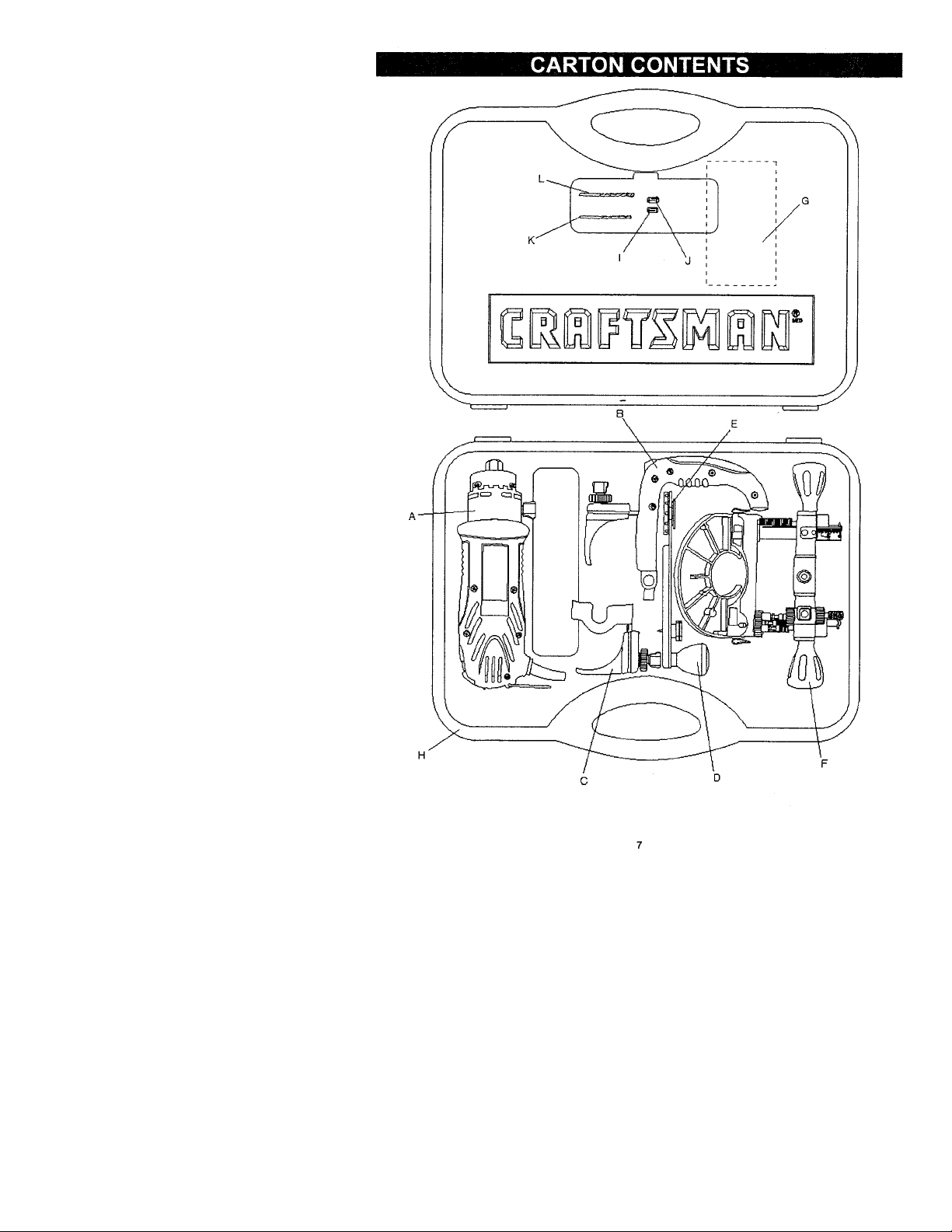
Carefully unpack the cutting tool and all its components
Compare against the "Cutting Tool Components" chart
below.
NOTE: See Page 7 for illustration of components.
I_, WARNING I
To avoid fire or toxic reaction, never use gasoline,
naphtha, acetone, lacquer thinner or similar highly
volatile solvents to clean the cutting toot.
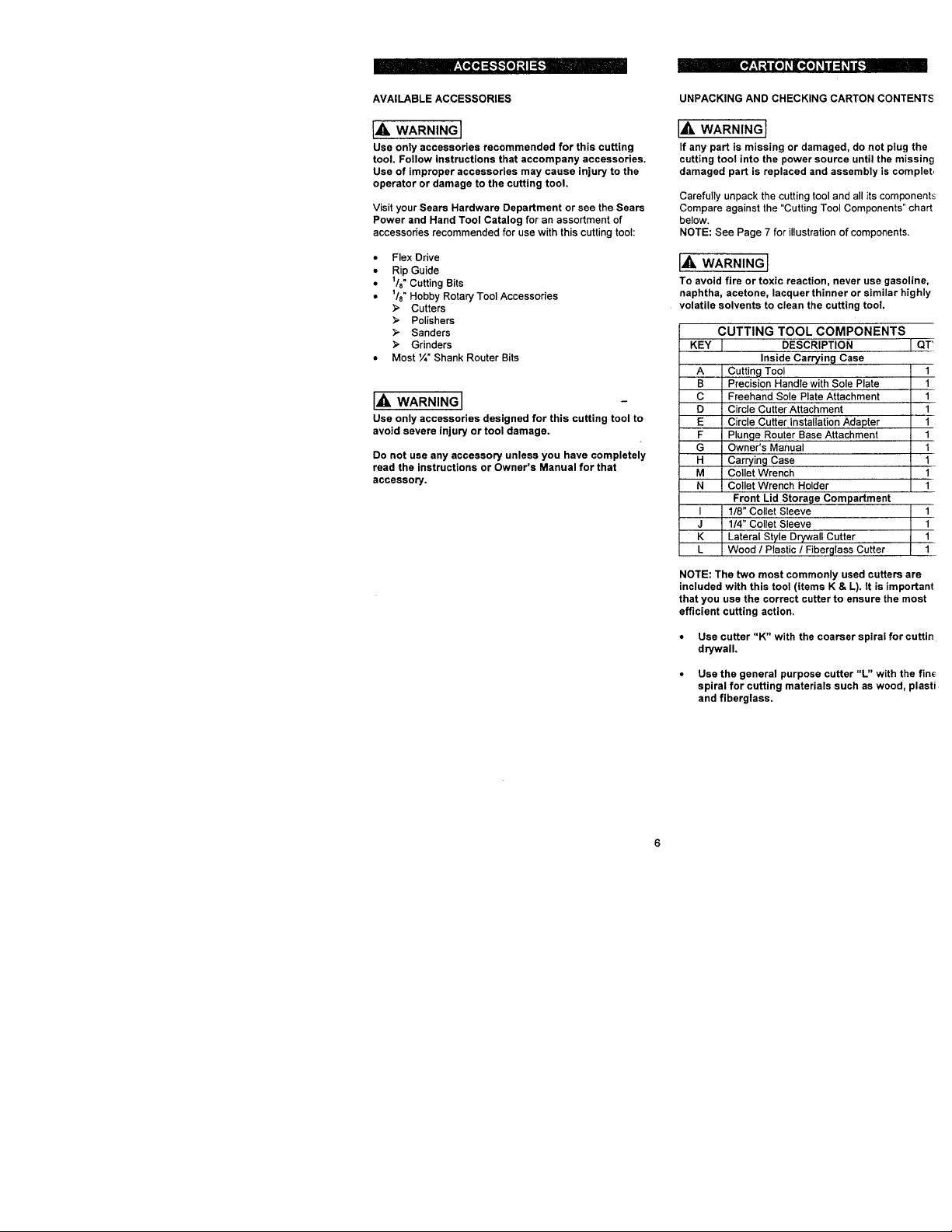
CUTTING TOOL COMPONENTS
KEY _ DESCRIPTION
B Precision Handle with Sole Plate 11
icu oo,
i i
I I 1/8" Collet Sleeve I 1
J I 1/4" Collet Sleeve 1
K Lateral Style Drywall Cutter I 1
L Wood / Past c / F berg ass Cutter 1
NOTE: The two most commonly used cutters are
included with this tool (items K & L). It is important
that you usa the correct cutter to ensure the most
efficient cutting action.
• Use cutter "K" with the coarser spiral for cuttin
drywall.
• Use the general purpose cutter "L" with the fin_
spiral for cutting materials such as wood, plasti
and fiberglass.
Inside Carrying Case
Freehand Sole Plate Attachment
Circle Cutter Attachment
Circle Cutter Installation Adapter
Plunge Router Base Attachment
Carryin 9 Case
Collet Wrench
Collet Wrench Holder
Front Lid Storage Compartment
-K
E
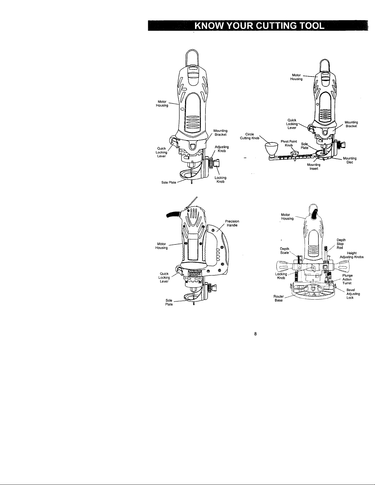
Motor
Housing
Motor
Housing
MounUng
Bracket
Quick Adjus_ng
Lever
Locking
Knob
Motor
Housing
_! Precision
Lockin
Lever
Sole _
Plate
Knob
Handle
Cutting
Circle
t
Lockinl
Knob
Router
Base
Motor
Housing
Quick
Lever
Moungng
Inse_
Mounting
Bracket
Disc
Depth
Stop
Rod
Height
Adjus_ng Knobs
Plunge
Action
Tu_et
Bevel
Adjusting
Lock
IA WARNINGI
Remove the plug from the power source before
assembly, changing accessories or cutters and
making adjustments. This safety action will help
prevent accidental starting of the tool which could
result in serious injury.
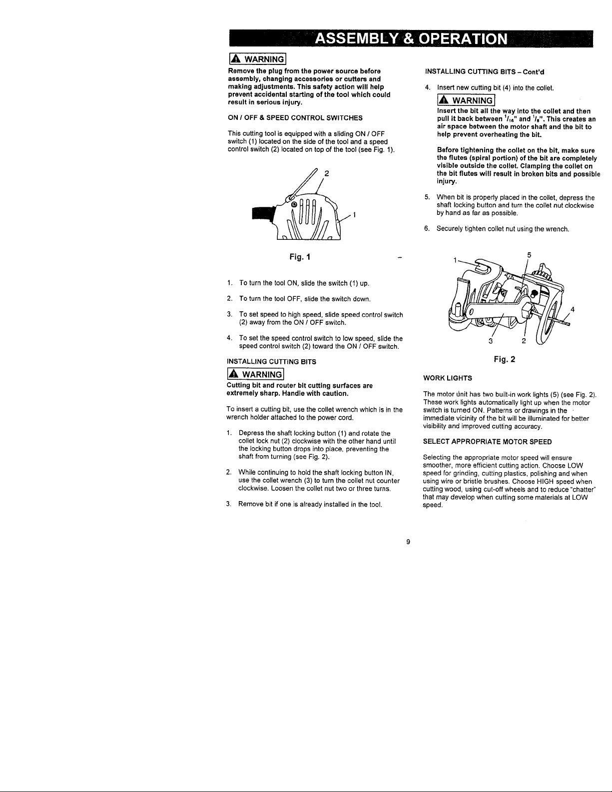
ON / OFF & SPEED CONTROL SWITCHES
This cutting tool is equipped with a sliding ON / OFF
switch (1) located on the side of the tool and a speed
control switch (2) located on top of the tool (see Fig. 1).
Fig. 1
1. To turn the tool ON, slide the switch (1) up.
2, To turn the tool OFF, slide the switch down.
3. To set speed to high speed, slide speed control switch
(2) away from the ON / OFF switch.
4. To set the speed control switch to low speed, slide the
speed control switch (2) toward the ON / OFF switch.
INSTALLING CUTTING BITS
I,A WARNING I
Cutting bit and router bit cutting surfaces are
extremely sharp. Handle with caution.
To insert a cutting bit, use the collet wrench which is in the
wrench holder attached to the power cord.
Depress the shaft locking button (1) and rotate the
collet lock nut (2) clockwise with the other hand until
the locking button drops into place, preventing the
shaft from turning (see Fig. 2).
2.
While continuing to hold the shaft locking button IN,
use the collet wrench (3) to turn the collet nut counter
clockwise. Loosen the collet nut two or three turns.
3. Remove bit if one is already installed in the tool.
INSTALLING CUTTING BITS - Cont'd
4.
Insert new cutting bit (4) into the collet.
I,A WARNING I
Insertthebitallthe way intothecolletand then
pullitback between 1/16"and 11s",This createsan
airspace between the motor shaftand the bitto
help prevent overheating the bit.
Before tightening the collet on the bit, make sure
the flutes (spiral portion) of the bit are completely
visible outside the collet. Clamping the collet on
the bit flutes will result in broken bits and possible
injury.
When bit is properly placed in the collet, depress the
shaft locking button and turn the collet nut clockwise
by hand as far as possible.
6. Securely tighten collet nut using the wrench.
3 2
Fig. 2
WORK LIGHTS
The motor LInit has two built-in work lights (5) (see Fig. 2).
These work lights automatically light up when the motor
switch is turned ON. Patterns or drawings in the -
immediate vicinity of the bit will be illuminated for better
visibility and improved cutting accuracy.
SELECT APPROPRIATE MOTOR SPEED
Selecting the appropriate motor speed will ensure
smoother, more efficient cutting action. Choose LOW
speed for grinding, cutting plastics, polishing and when
using wire or bristle brushes. Choose HIGH speed when
cutting wood, using cut-off wheels and to reduce "chatter"
that may develop when cutting some materials at LOW
speed.
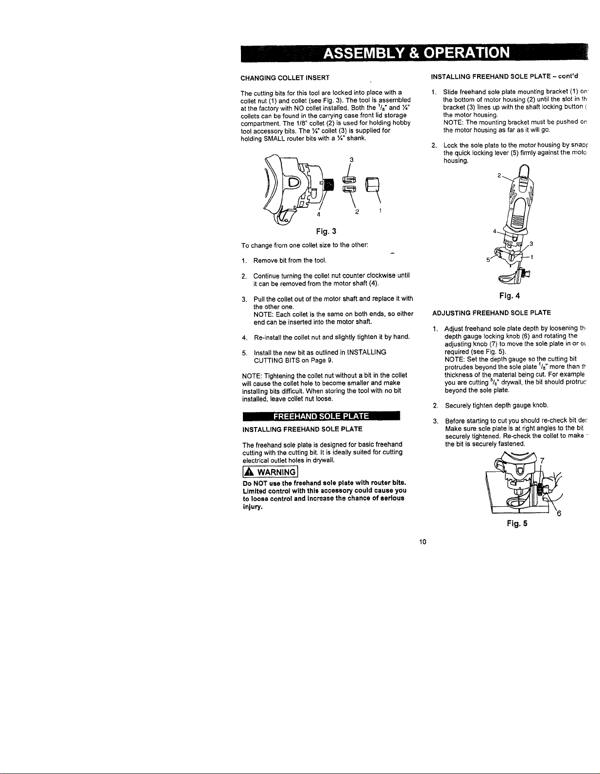
CHANGING COLLET INSERT
The cutting bits for this tool are locked into place with a
collet nut (1) and collet (see Fig. 3). The tool is assembled
at the factory with NO collet installed. Both the 118"and ¼"
collets can be found in the carrying case front lid storage
compartment. The 1/8" collet (2) is used for holding hobby
tool accessory bits. The ¼" collet (3) is supplied for
holding SMALL router bits with a ¼" shank.
3
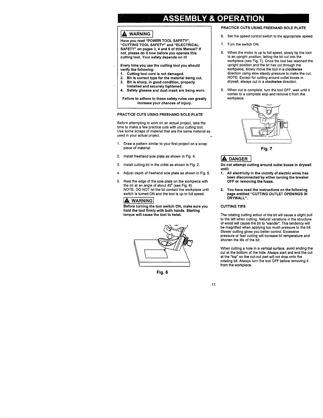
INSTALLING FREEHAND SOLE PLATE - cont'd
Slide freehand sole plate mounting bracket (1) on"
the bottom of motor housing (2) until the slot in th
bracket (3) lines up with the shaft locking button /
the motor housing,
NOTE: The mounting bracket must be pushed on
the motor housing as far as it will go.
Lock the sole plate to the motor housing by snapr
the quick locking lever (5) firmly against the mote
housing.
2
4 2 1
Fig. 3
To change from one collet s_e to the other:
1. Remove bitfrom the tool.
2. Continue turning the collet nut counter clockwise until
it can be removed from the motor shaft (4).
3. Pull the collet out of the motor shaft and replace it with
the other one.
NOTE: Each collet is the same on both ends, so either
end can be inserted into the motor shaft.
4. Re-install the collet nut and slightly tighten it by hand.
5. Install the new bit as outlined in INSTALLING
CUTTING BITS on Page 9.
NOTE: Tightening the collet nut without a bit in the collet
will cause the collet hole to become smaller and make
installing bits difficult. When storing the tool with no bit
installed, leave collet nut loose,
INSTALLING FREEHAND SOLE PLATE
The freehand sole plate is designed for basic freehand
cutting with the cutting bit. It is ideally suited for cutting
electrical outlet holes in dr/wall.
IA WARNINGI
Do NOT use the freehand sole plate with router bits.
Limited control with this accessory could cause you
to loose control and inc_ase the chance of serious
injury.
!
,3
5
ADJUSTING FREEHAND SOLE PLATE
Adjust freehand sole plate depth by loosening th,
depth gauge locking knob (6) and rotating the
adjusting knob (7) to move the sole plate in or eL
required (see Fig. 5).
NOTE: Set the depth gauge so the cutting bit
protrudes beyond the sole plate 1/8"more than tt_
thickness of the material being cut. For example
you are cutting s/s" drywall, the bit should protru¢
beyond the sole plate.
2.
Securely tighten depth gauge knob.
3.
Before starting to cut you should re-check bit der
Make sure sole plate is at right angles to the bi!
securely tightened. Re-check the collet to make -
the bit is securely fastened.
L--1
Fig. 4
Fig. 5
10
IAWA"NINGI
Have you read "POWER TOOL SAFETY",
"cu'n'ING TOOL SAFETY" and "ELECTRICAL
SAFETY" on pages 3, 4 and 5 of this Manual? If
not, please do it now before you operate this
cutting tool. Your safety depends on itl
Every time you use the cutting tool you should
verify the following:
1. Cutting tool cord is not damaged.
2. Bit is correct type for the material being cut.
3. Bit is sharp, in good condition, properly
installed and securely tightened.
4. Safety glasses and dust mask are being worn.
Failure to adhere to these safety rules can greatly
increase your chances of injury.
PRACTICE CUTS USING FREEHAND SOLE PLATE
Before attempting to work on an actual project, take the
time to make a few practice cuts with your cutting tool
Use some scraps of material that are the same material as
used in your actual project.
1. Draw a pattern similar to your first project on a scrap
piece of material.
2. Install freehand sole plate as shown in Fig. 4.
3. Install cutting bit in the collet as shown in Fig. 2.
4. Adjust depth of freehand sole plate as shown in Fig. 5.
5.
Rest the edge of the sole plate on the workpiece with
the bit at an angle of about 45= (see Fig. 6).
NOTE: DO NOT let the bit contact the workpiece until
switch is turned ON and the tool is up to full speed.
I_ WARNING I
Before turningthetoolswitch ON, make sure you
hold the toolfirmlywith both hands, Starting
torque willcause the toolto twist,
Fig. 6
PRACTICE CUTS USING FREEHAND SOLE PLATE
6. Set the speed control switch to the appropriate speed.
7. Turn the switch ON.
When the motor is up to full speed, slowly tip the tool
to an upright position, letting the bit cut into the
workpiece (see Fig. 7). Once the tool has reached the
upright position and the bit has cut through the
workpiece, slowly move the tool in a clockwise
direction using slow steady pressure to make the cut.
NOTE: Except for cutting around outlet boxes in
drywall, always cut in a clockwise direction.
When cut is complete, turn the tool OFF, wait until it
comes to a complete stop and remove it from the
workpiece.
Fig. 7
I_, DANGER I
Do not attempt cutting around outlet boxes in drywall
until:
1. All electricity in the vicinity of electric wires has
been disconnected by either turning the breaker
OFF or removing the fuses.
2. You have read the instructions on the following
page entitled "CUTTING OUTLET OPENINGS IN
DRYWALL".
CUTTING TIP,S
The rotating cutting action of the bitwill cause a slight pull
to the left when cutting. Natural variations in the structure
of wood will cause the bit to "wander'. This tendency will
be magnified when applying too muchpressure to the bit.
Slower cutting gives you better control. Excessive
pressure or fast cutting will increase bit temperature and
shorten the life of the bit.
When cutting a hole in a vertical surface, avoid ending the
cut at the bottom of the hole. Always start and end the cut
at the "top" so the cut-out part will not drop onto the
rotating bit. Always turn the tool OFF before removing it
from the workpiece.
11
CUTTING OUTLET OPENINGS IN DRYWALL
IA DANGER I
Do not attempt to use this tool to make out-outs
around any fixture or opening which has live electrical
wires or on any wall which may have electrical wiring
behind it. If a live wire is contacted, the bit could
conduct the electric current to the tool, creating an
electrocution hazard for the operator. Turn OFF
breakers or remove fuses to disconnect the electric
circuit in the area of work, Always hold the tool by its
insulated housing when working in areas where there
is a possibility of contacting electric wires. Always
wear eye protection when operating this tool.
Before installing drywall, push the electrical wires to
the back of the box as far as possible so they will not
be cut by the bit when cutting the opening,
Before fastening the drywall sheet over the electrical
box, mark the sheet as close as possible to the center
of the box opening. Mark should be on the side of the
drywall facing you.
When fastening the drywall in place, do not plaee nails
or screws closer than 12" from the box. This will
prevent the drywall from becoming deformed under
pressure.
4.
Insert cutting bit and install freehand sole plate as
outlined on Pages 9 & 10 of this Owner's Manual.
Adjust depth of cut so the bit will protrude 1/8"beyond
the thickness of the drywall.
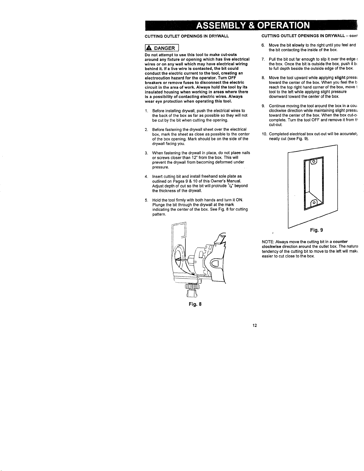
Hold the tool firmly with both hands and turn it ON.
Plunge the bit through the drywall at the mark
indicating the center of the box. See Fig. 8 for cutting
pattern.
cu'n'ING OUTLET OPENINGS IN DRYWALL - con_'
6.
Move the bit slowly to the right until you feel and
the bit contacting the inside of the box.
7.
Pull the bit out far enough to slip it over the edge
the box. Once the bit is outside the box, push it b_
to full depth beside the outside edge of the box.
Move the tool upward while applying slight pressL
toward the center of the box. When you feel the b
reach the top right hand corner of the box, move t
tool to the teft while applying slight pressure
downward toward the center of the box,
Continue moving the tool around the box in a cou,
clockwise direction while maintaining slight pressu
toward the center of the box. When the box cut-o_
complete. Turn the tool OFF and remove it from t,_
cut-out.
10.
Completed electrical box cut-out will be accuratel_
neatly cut (see Fig. 9).
Fig. 8
Fig. 9
NOTE: Always move the cutting bit in a counter
clockwise direction around the outlet box. The natura
tendency of the cutting bit to move to the left will mak_
easier to cut close to the box.
12
•"lr_g.l =15"
INSTALLING PRECISION HANDLE
The precision handle is designed for use when precision
control over the tool movement is desired. The
comfortable handle can be used with either the right or left
hand.
Slide precision handle mounting bracket (1) onto the
bottom of motor housing (2) until the slot under the
handle (3) lines up with the shaft locking button (4) in
the motor housing (see Fig. 10).
NOTES:
a) The mounting bracket must be pushed onto the
motor housing as far as it will go.
b) The shaft locking button (5) can now be activated
by your thumb while holding on to the precision
handle
Lock the precision handle to the motor housing by
snapping the quick locking lever (6) firmly against the
motor housing.
6 4
5
Fig. 10
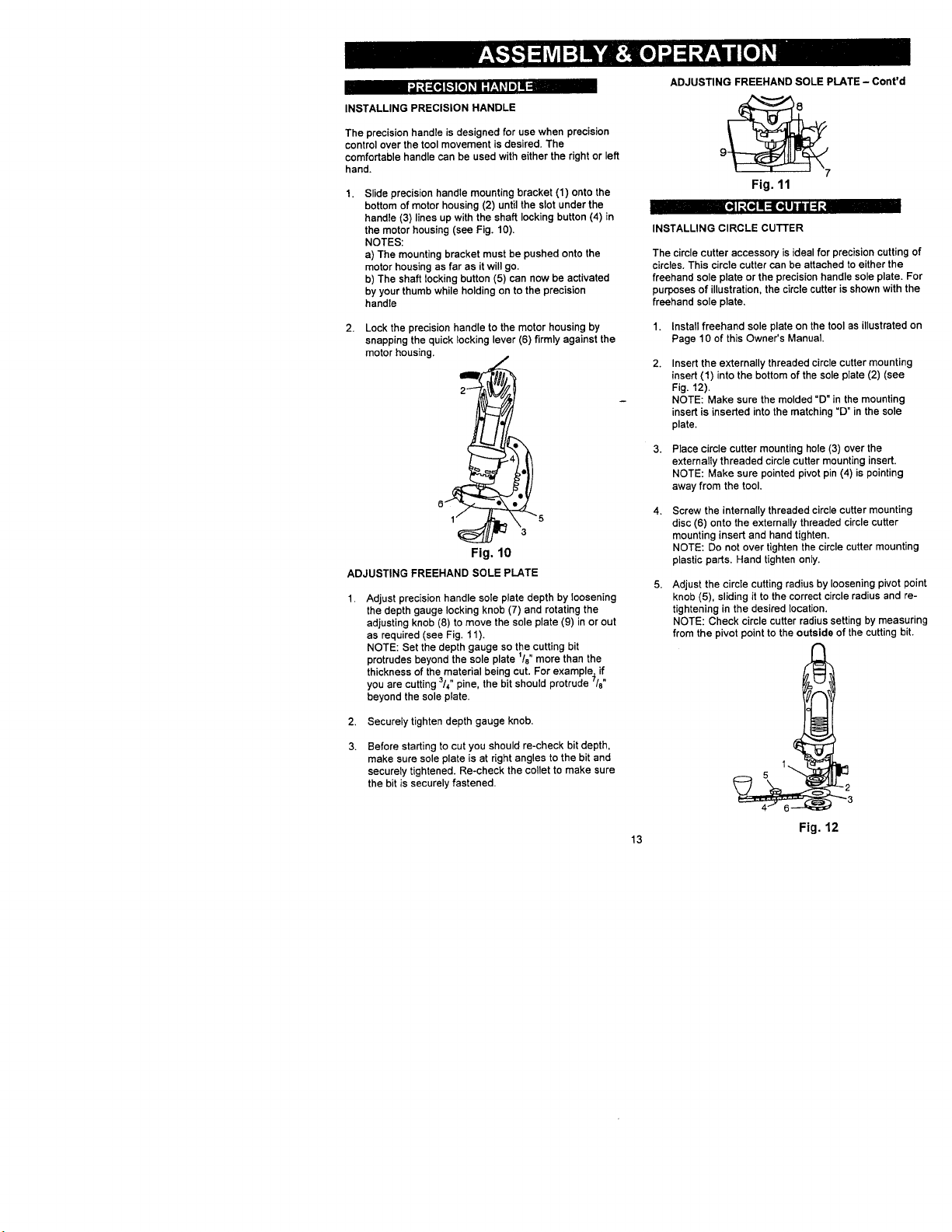
ADJUSTING FREEHAND SOLE PLATE
Adjust precision handle sole plate depth by loosening
the depth gauge locking knob (7) and rotating the
adjusting knob (8) to move the sole plate (9) in or out
as required (see Fig. 11).
NOTE: Set the depth gauge so the cutting bit
protrudes beyond the sole plate 1/8"more than the
thickness of the material being cut. For example, if
you are cutting 3/4" pine, the bit should protrude 7/8"
beyond the sole plate.
2.
Securely tighten depth gauge knob.
3.
Before starting to cut you should re-check bit depth,
make sure sole plate is at right angles to the bit and
securely tightened. Re-check the coltet to make sure
the bit is securely fastened.
ADJUSTING FREEHAND SOLE PLATE - Cont'd
9 v 8
Fig. 11
INSTALLING CIRCLE CUTTER
The circle cutter accessory is ideal for precision cutting of
circles. This cimle cutter can be attached to either the
freehand sole plate or the precision handle sole plate. For
purposes of illustration, the circle cutter is shown with the
freehand sole plate,
1.
Install freehand sole plate on the tool as illustrated on
Page 10 of this Owner's Manual.
2.
Insert the externally threaded circle cutter mounting
insert (1) into the bottom of the sole plate (2) (see
Fig. 12).
NOTE: Make sure the molded "D" in the mounting
insert is inserted into the matching "D" in the sole
plate.
Place circle cutter mounting hole (3) over the
externally threaded circle cutter mounting insert.
NOTE: Make sure pointed pivot pin (4) is pointing
away from the tool.
Screw the internally threaded circle cutter mounting
disc (6) onto the externally threaded circle cutter
mounting insert and hand tighten.
NOTE: Do not over tighten the circle cutter mounting
plastic parts. Hand tighten only.
Adjust the circle cutting radius by loosening pivot point
knob (5), sliding it to the correct circle radius and re-
tightening in the desired location.
NOTE: Check circle cutter radius setting by measuring
from the pivot point to the outside of the cutting bit.
-2
"_"3
13
Fig. 12
I I ll:ll!llltlli/l_ III
CIRCLE CURER OPERATION
[_ WARNING]
Unplug the tool from the power source before
changing accessories, changing bite and making
adjustments.
Before turning the tool ON, check to make sure bit
and all accessory fasteners are securely tightened.
1. Mark the center of the circle you wish to cut on the
workpiece and drill a 6 mm or isle4" pilot hole.
2. Adjust cutting bit depth to lie" longer than the
thickness of the material being cut (see Fig. 5).
3. Adjust the circle cutting radius by loosening pivot point
knob, sliding it to the correct circle radius and re-
tightening in the desired location.
NOTE: Check circle cutter radius setting by measuring
from the pivot point to the outside of the spiral bit.
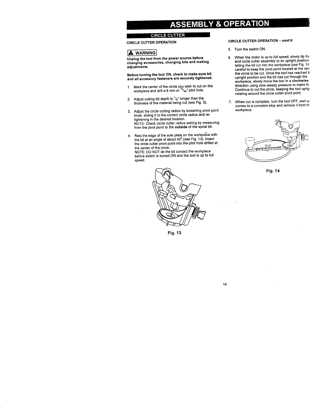
4.
Rest the edge of the sole plate on the workpi_ce with
the bit at an angle of about 45 °.(see Fig. 13). Insert
the circle cutter pivot point-into the pilot hole ddlled at
the center of the circle.
NOTE: DO NOT let the bit contact the workpiece
before switch is turned ON and the tool is up to full
speed.
CIRCLE CUTTER OPERATION - cont'd
5. Turn the switch ON.
When the motor is up to full speed, slowly1
and circle cutter assembly to an upright pc
letting the bit cut into the workpiece (see F
careful to keep the pivot point located at tt"
the circle to be cut. Once the tool has reac
upright position and the bit has cut througt
workpiece, slowly move the tool in a clock
direction using slow steady pressure to ms
Continue to cut the circle, keeping the tool
rotating around the circle cutter pivot point
When cut is complete, turn the tool OFF, v
comes to a complete stop and remove it fr
workpiece.
\
Fig. 14
Fig, 13
14
• ImB = I_Ul_,[€_:41_ellJ.l_ KY-,_::II
The router accessory converts your cutting tool intoa
small hobby plunge router that is capable of handling
sman ¼" shank router bits as well as the spiral cutting bit.
The tilting base is ideal for bevel cutting. The plunge
feature allows you to pro-set up to three different cutting
depths.
[,_ WARNING I
Unplug the tool from the power source before
changing accessories, changing bits and making
adjustments.
Before turning the tool ON, check to make sure the bit
and all accessory fasteners are securely tightened.
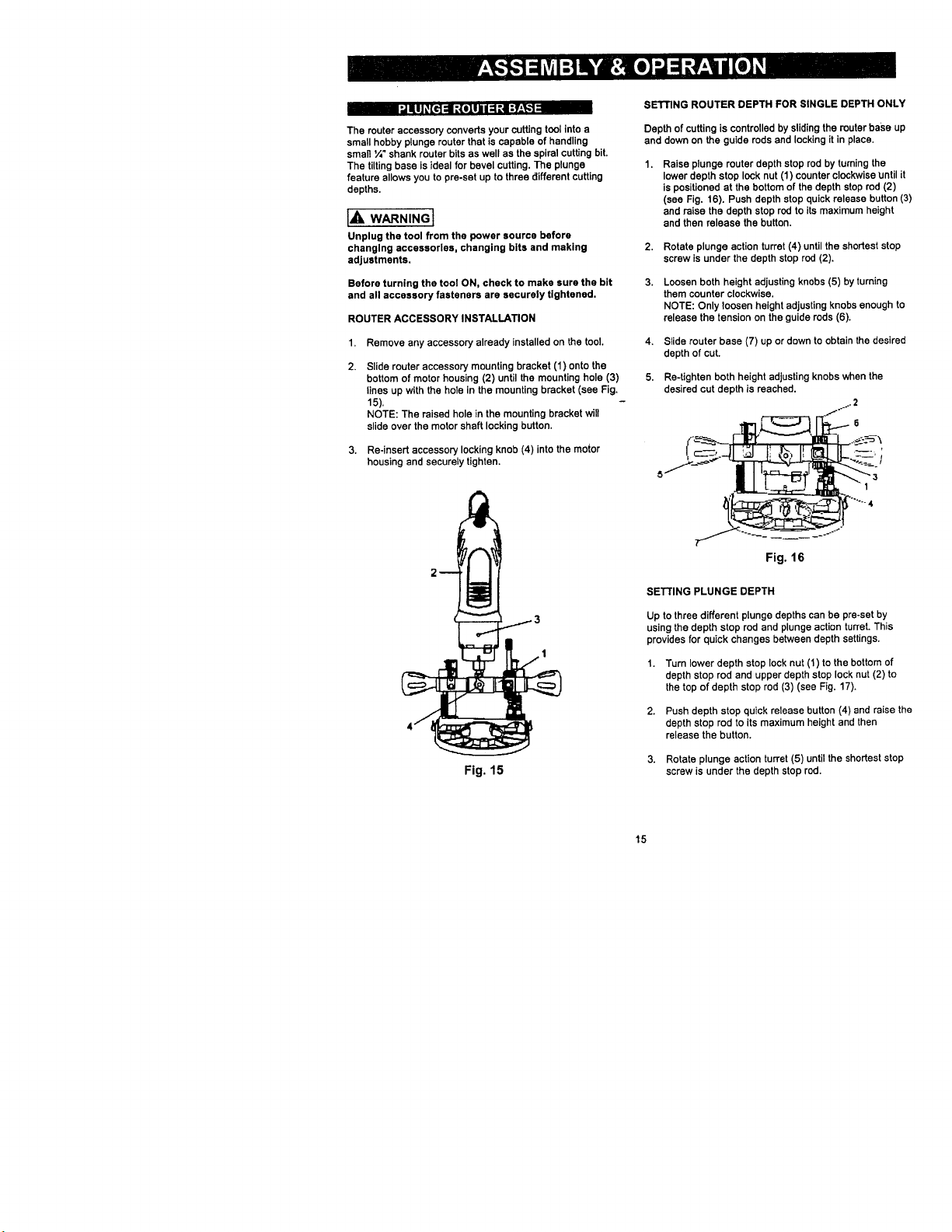
ROUTER ACCESSORY INSTALLATION
1.
Remove any accessory already installedon the tool.
2.
Slide router accessory mounting bracket (1) onto the
bottom of motor housing (2) until the mounting hole (3)
lines up with the hole in the mounting bracket (see Fig.
15).
NOTE: The raised hole in the mounting bracket will
slide over the motor shaft locking button.
3.
Re-insert accessory locking knob (4) into the motor
housing and securely tighten.
SETTING ROUTER DEPTH FOR SINGLE DEPTH ONLY
Depth of cuttingis controlled by slidingthe router base up
and down on the guide rods and lockingit in place.
Raise plunge router depth stop rod by turningthe
lower depth stop lock nut (1) counter clockwise until it
is positioned at the bottom of the depth stop rod (2)
(see Fig. 16). Push depth stop quick release button (3)
and raise the depth stop rod to its maximum height
and then release the button.
2.
Rotate plunge action turret (4) untilthe shortest stop
screw is under the depth stop rod (2).
3.
Loosen both height adjusting knobs (5) by turning
them counter clockwise.
NOTE: Only loosen height adjusting knobs enough to
release the tension on the guide rods (6).
4,
Slide router base (7) up or down to obtain the desired
depth of cut.
5.
Re-tighten both height adjusting knobs when the
desired cut depth is reached.
Fig. 15
Fig. 16
SETrlNG PLUNGEDEPTH
Up to three different plunge depths can be pre-set by
using the depth stop rod and plunge action turret. This
provides for quick changes between depth settings.
1. Turn lower depth stop lock nut (1) to the bottom of
depth stop rod and upper depth stop lock nut (2) to
the top of depth stop rod (3) (see Fig. 17),
2. Push depth stop quick release button (4) and raise the
depth stop rod to its maximum height and then
release the button,
3. Rotate plunge action turret (5) until the shortest stop
screw is under the depth stop rod.
15
SETTINGPLUNGEDEPTH-cont'd
4,
Loosen both height adjusting knobs (6) by tuming
them counter clockwise.
NOTE: Only loosen height adjusting knobs enough to
release the tension on the guide rods (7).
5.
Slide router base (8) up or down to obtain the desired
depth of cut.
6.
Re-tighten height adjusting knobs when the desired
cut depth is reached.
7.
Push the depth stop quick release button and lower
depth stop rod until it contacts the turret stop screw
(9). After releasing the quick release button, finer
adjustments can be made by tuming the depth stop
rod.
8,
Lock both lhe lower (1) and upper (2) depth stop lock
nuts against the router body to lock the depth stop rod
in place.
NOTE: Do not use pliers to tighten lock nuts. T_um
lock nuts by hand only.
9.
Lock shortest turret stop screw by tightening lock nut
(10).
NOTE: Do not over tighten lock nut.
10. Loosen both height adjusting knobs just enough to
allow rouler to freely slide up and down on the guide
rods.
11. Two additional depths can be pre-set in a similar way
setting the other two turret stop screws to the desired
depth.
NOTE: To select pre-set plunge depth, simply rotate
the turret until the correct turret stop screw is aligned
under the depth stop rod.
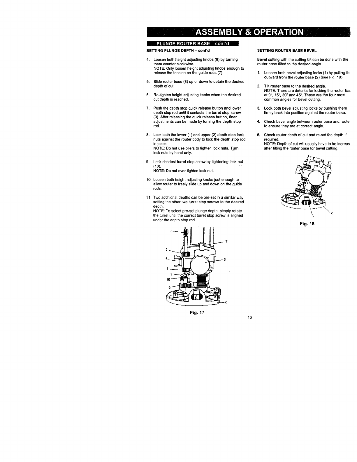
SETTING ROUTER BASE BEVEL
Bevel cutting with the cutting bit can be done with the
router base tilted to the desired angle.
I. Loosen both bevel adjusting locks (1) by pulling th_
outward from the router base (2) (see Fig. 18).
2.
Tilt router base to the desired angle.
NOTE: There are detents for locking the router ba_
at O°, 15°, 300and 45 °. These are the four most
common angles for bevel cutting.
3. Lock both bevel adjusting locks by pushing them
firmly back into positionagainst the router base.
4. Check bevel angle between router base and router
to ensure they are at correct angle.
5.
Check router depth of cut and re-set the depth if
required.
NOTE: Depth of cut will usually have to be increas,
after tilting the router base for bevel cutting.
'"2
Fig. 18
1
9
Fig. 17
16
 Loading...