

Craftsman 183172500 Owner’s Manual
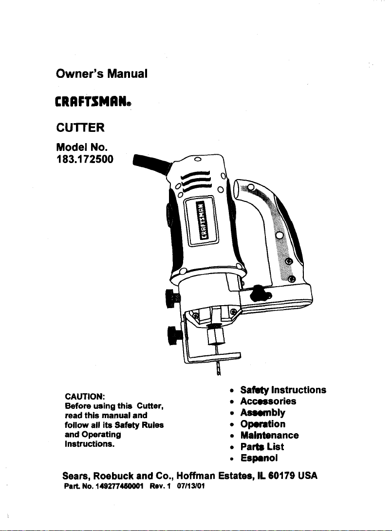
Owner's Manual
CRRFTSMANe
CUTTER
Model No.
183.172500
CAUTION:
Before using this Cutter,
read this manual and
follow all its Safety Rules
and Operating
Instructions.
• SafIty Instructions
• Accessories
• Assembly
• Operation
• Maintenance
• Parts List
• Espenol
Sears, Roebuck and Co., Hoffman Estates, IL 60179 USA
ParL No. 149277480001 Rev. 1 07/13/01
SECTION PAGE
warranty ........................................ 2
Product Specifications ....................... 2
Power Tool Safety ............................ 3
Cutter Safety ..................................4
Elech'icalRequirements & Safety........5
Accessories ....................................5
SECTION PAGE
Carton Contents .............................. 6, 7
Know Your Cutl_. ............................. 8
Assembly & OpemUon ...................... 9 - 17
Maintenance ................................... 17
Repair Parts ................................... 18 - 22
Parts & Service Availability ................ 23
llllJ
FULL ONE YEAR WARRANW
If this Cutter fails due to a defect in material or workmanship within one year of date of
purchase,Sears will at itsoptionrepair orreplace itfree of charge.
Returnthis Cutterto a Sears Service Center for repair,or to place of purchase for replacement.
This warranty gives you specific legal fights, and you may also have other rights which may vary
from state to state.
Seam, Roebuck and Co., Dept. 817 WA, Hoffman Estates, IL 60179
l& WARNING I
Some dust created by power sanding, sawing, grinding, drilling and other coaMructlon activities contains
chemlcaia known (to the State of California) to cause cancer, birth defects or olther reproductive harm. Some
exampfes of these chemicals are:
• Lead from iaad-based paints
• Crystalline silica Wont bricks, cement and other masonry products
• Arsenic and chrominm from chem..ally treated lumber
Your risk from these exposure varies, depending on how often you do this type of work. To reduce your
expo6ure to these chemicals, work In a well ventliated area and wod( _ approvad safety equipment such as
those dust masks that ere specially designed to filter out microscopic parl_.
l;,l [o] lU[oM
Motor Rating ...................... 120V, 60Hz, AC Motor Horsepower ...... tl3 HP (Ma_mum Developed)
Amperes ........................... 4.0 Amperes Weight ..................... 3.75 kg
Speed (no load) .................. 30000 RPM
I,_, WARNINGI
To avoid electrical hazards, fire hazards or damage to the cutter, use proper circuit protection.
This cutter is wired atthe factory for110-120 Volt operation. It must be connecl_d to a 110-120 Voit115 Ampere
time delay fuse or curcuit breaker. To avoid shock or fire, replace power cord immediately If It is worn, cut or
damaged in any way.
Before using your cutter, It is crltinal that you read and undemtand these mlGety rules. Failure to follow these
miss could result in serious injury to you or damage to the cutter.

[A WARNINGJ
Before using your cutter, it is critical that you read and understand these safety rules. Failure
to follow these rules could result in serious injury to you or damage to the cutter.
15,
Good safe_ practices are a combina_n of common
sense, staying alert and undemtanding howto use your
power tool. To avoid mistakes that could cause sedous
mJury, do not plug in your cutter until you have read and
understood the following safety rules:
1. READ and become familiar with this entire Owner's
Manual. LEARN the tool's applications, limitations and
possible hazards.
2.IA WARNINGJ
Look for this symbol that identif'ms important safety
precautions. It means CAUTIONI BECOME ALERTt
YOUR SAFETY IS INVOLVEDI
3. KEEP GUARDS IN PLACE and in working order.
4. DO NOT USE IN A DANGEROUS ENVIRONMENT
such as damp orwet locations or exposure to rain.
Keep work area well lighted.
5. DO NOT use power toolsinthe presence of
flammable liquidsor gases.
6. KEEP WORK AREA CLEAN. Cluttered areas and
workbenches invite accidents.
7. KEEP CHILDREN AWAY. All visitors should be kept
at a safe distance from the work area.
8. DO NOT FORCE THE TOOL ItwHIdothejobbetter
and safer at the rate for which if was designed.
9. USE THE RIGHT TOOL. Do not force the tool or
attachment to do a job for which it is not designed.
10. WEAR PROPER APPAREL. DO NOT wear loose
clothing, gloves, neckties, rings, bracelets or other
jewelry that may get caught in moving pans. Non-slip
footwear is recommended. Wear protective hair
covering to contain long hair.
11. WEAR A FACE MASK OR DUST MASK. Sawing,
cutting, drilling and sanding operations produce
hazardous dust.
12. DIe, CONNECT TOOLS FROM THE POWER
SOURCE before servicing and when changing
accessories such as blades, bits, cutters, etc.
13. REDUCE THE RISK OF UNINTENTIONAL
STARTING. Make sure the switch is in the "OFF"
position before plugging into the power source.
14. USE ONLY RECOMMENDED ACCESSORIES.
Consult the Owner's Manual for recommended
accessories. The use of improper accessories may
cause injury to you or damage to the tool.
REMOVE ADJ_ KEYS AND WRENCHES.
Form the habit of checking to see that keys and
adjusting wrenches are removed from the tool before
turning "ON'.
16.
NEVER LEAVE TOOL RUNNING UNATTENDED.
TURN THE POWER "OFF". Do not leave the tool
before it comes to a complete stop.
17.
NEVER STAND ON TOOL. Serious injury could
occur ifthe tool is tipped or if the cutting tool is
unintentionally contacted.
18.
DO NOT OVERREACH. Keep proper footing and
balance at all times.
19. MAINTAIN TOOt_ WITH CARE. Keep tools sharp
and clean for molt efficient and safest performance.
Follow instruc_ofls for lubricating and changing
accessories.
20. CHECK FOR D_Mt, GED PARTS. Before further use
of the tool, a guaed or other part that is damaged
should be carefuNy checked to ensure it will operate
properly and perfoml its intended function. Check for
alignment of moving parts, binding of moving parts,
mounting and any _her conditions that may affect its
safe operation. Aguard or other part that is damaged
should be properly repaired or replaced.
21. MAKE WORKI_IOIP CHLD PROOF with padlocks,
master switches or by removing starter keys.
22. DO NOT operate the tool if you are under the
influence of any drugs, alcohol or medication that
could impair your abHify to use the tool safely.
23. USE DUST COLLECTION SYSTEM wherever
ossible. Dust generstod from certain materials can
e hazardous to your health and in some cases, a fire
hazard. Always operate the power tool in a well
ventilated area with adequate dust removal.
24.
ALWAYS WEAR EYE PROTECTION. Any power
ANSI safety stenderd Z87.1. Everyday glasses have
only impact reststont lenses. They ARE NOT safety
glasses. Safety goggles are available at Sears.
tool can throw foreign objects
into your eyes which could
cause permanent eye damage.
ALWAYS wear safety goggles
(not glasses) that comply with
I& WARNll_I
Glasses or gollIlII not In compliance with ANSI
Ztt7.1 could cI I_dous injury when they break.
SAVE THESE INSTRUCTIONS FOR REFERENCE

_ARNING_
For your safety, do not plug in your cutter or try to
use any accessory until it is complemly assembled
and installed according to these Instructions, and
until you have read and understood this Owner's
Manual.
Failure to follow these safety rules will result in risk of
serious injury.
1. WEAR EYE PROTECTION. This high speed tool will
throw particles from the workpiece during operation.
Make sure safety glasses have side shields.
2. USE FACE OR DUST MASK along with safety
goggles if cutting or routing operation is dusty. Make
sure work area is well ventilated.
3.
USE HEARING PROTECTION, particularly during
extended periods of operation.
4.
NEVER USE DULL OR DAMAGED BITS. Damaged
bits can break without warning. Dull bits may ovedoad
the motor, cut slowly and are difficult to control. They
will also overheat and possibly break.
ALWAYS MAKE SURE THE WORKPIECE IS FREE
OF NAILS AND OTHER FOREIGN OBJECTS. If the
bit strikes a nail it will jump sideways and possibly
break.
6. DO NOT USE THIS TOOL FOR DRILLING HOLES.
It is NOT intended to be used as a ddll.
ALLOW CLEARANCE UNDER WORKPIECE for bit
to b'avel. Never place workpiece on hard surfaces
such as concrete etc. The bitmay jump or break
when contacting a surface other than the one being
cut.
ALWAYS SET THE DEPTH GUIDE TO THE
APPROPRIATE DEPTH. Use tool with the depth
guide flat against the work surface for better control of
the tool.
9. NEVER USE THE TOOL wrrHOUT THE SOLE
PLATE, PRECISION HANDLE OR ROUTER BASE
attached and appropriately adjusted.
10. ALWAYS CLAMP WORKPIECE TO HOLD IT
STEADY WHEN CUTTING. This will free both hands
for operating the tool.
11. NEVER HOLD THE WORKPIECE IN ONE HAND
while operating the fool with the other hand.
12. NEVER PLACE HANDS IN THE PATH OF THE
CUTTER AND UNDER THE WORKPIECE.
13. NEVER START THE TOOL WHEN THE BIT IS
TOUCHING THE WORKPECE. The bit may catch
the workpiece causing loss of control.
14. ALWAYS HOLD THE TOOL WITH TWO HANDS
DURING START-UP AND OPERATION. When
starting, motor torque will cause the tool to twisL
15. TURN OFF ALL CIRCUIT BREAKERS AND
REMOVE ALL FUSES in the work area when cutting
into walls or blind areas.
16. ALWAYS HOLDTHE TOOL BY THE INSULATED
GRIPPING _UlIRFACES ON THE BODY OF THE
TOOL where fllere is any possibility of the cutter
contacting hidden elecb'ical wires or the cord of the
tool. Contectwith "live" wires will make exposed
metal parts of the tool _live" causing an electrical
shock to the operator.
17.
WHEN CUTTING DRYWALL ELECTRICAL OUTLET
OPENINGS using the outlet as a guide, always cut in
a counter c_ direction. The natural tendency
of the tool to pull to the left will cause a "hugging"
action toward the outlet box, resulting in a heater cut.
18. NEVER LAY THE TOOL DOWN UNTIL THE
CUTTER COB TO A COMPLETE STOP. A
spinning bit (:an come in contact with the surface and
pull it out of yqmr con_ol.
19. NEVER TOU_H THE BIT IMMEDIATELY AFTER
USE. The bit!will be too hot to be handled with bare
hands and _dll bum your fingers.
20. ALWAYS RI_TI_HTEN COLLET AND ALL
ADJUSTMIENT8 before starting the tool after a bit or
accessory h_ been changed. Loose bits and
adjuskneolB_ cause unexpected shifting of the tool,
resulting in I_ bf control and injury from the bit or
cutter being thmt_.
SAVE THESE INSTRUCTIONS FOR REFERENCE

[lJli=|ilPl_k_._--"'Jllll].
This cutter is double insulated to protect you from
electrical shock.
IA WARNING I
Double insulated tools am equipped with a polarized
plug (one blade is wider than the other). This plug will
f_ into a polarized outlet only one way. If the plug
does not fit fully into the outlet, reverse the plug. If it
still does not fit, contact a qualified etacITIclan to
install a polarized outlet. Do not alter the plug in any
way. Double insulation eliminates the need for the three
wire grounded power cord and grounded power supply
system.
Avoid body contact wlth grounded surfaces such as
pipes, radiators, ranges and refrlgerators. There is an
increased riskof electric shock if your body is grounded.
Do not expose power tools to rain or wet conditions.
Water entering a power tool will increase the risk of
electric shock.
Do not abuse the cord. Never use the cord to carry
the tool or pull the plug from the outteL Keep cord
away from heat, oil, sharp edges and moving parts.
Replace damaged cords immediately. Damaged cords
increase the risk of electhc shook.
When operaUng a power tool outdoors, use an
outdoor exteesfon cord marked "W-A" or"W". These
cords are rated for outdoor use and reduce the risk of
electric shock.
IA, WARNING I
Always make sure the receptacle Is polarized. If you
are not sure, have a qualified electllclsn check the
receptacle.
[ellJll]illl_lile]:l 1:l)[41l:ll_k'l[I]_: [ata];llk
Make sure your extension cord is in good condWon.
When using an extension cord, be sure to use one heavy
enough to carry the current the tool will draw. An
undersized cord will cause a drop in line voltage resulting
in loss of power told overheating. The table below shows
the correct size to use according to cord length and
nameplate ampere rating. If in doubt, use the next heavier
gauge. The smager the gauge number the heavier the
cord.
Be sure your extension conS is properly wired and in
good condition, Always replace a damaged extension
cord or have it repaked by a qualified electrician before
using it. Proteet your extension cord from sharp objects,
excessive heat and damp or wet areas.
Use a separate electrical circuit for your power tools.
This circuit must not be less than 14 gauge wire and
should be protected with either a 15 Ampere time delay
fuse or circuit breaker. Before connecting the power tool
to the power source, make sure the switch is in the OFF
position and the power source is the same as indicated on
the nameplate. Running at lower voltage will damage the
motor.
IA WARNINOI
Repair or rspla¢l) damaged or worn extension cords
immediately.
Select the appropriate extension cord gauge and length
using the chart below.
MINIMUM GAUGE (AWG) EXTENSION CORDS
Ampere Rating Total length in feet
More Than More Than 25' 50' 100' 150'
0 6 18 16 16 14
12 16 14 12 NOtApplicable
(120 Volt use only)
Not
0 10 18 16 14 12
12 16 16 14 12
_A WARNINGI
Keep the extm_ cord clear of the working area.
Position the coRl so It will not get caught on the
workptace, too_ or any other obstructions while you
are working w#h the power tool.
_Xo(o] II.$'_o] =]i;i_'
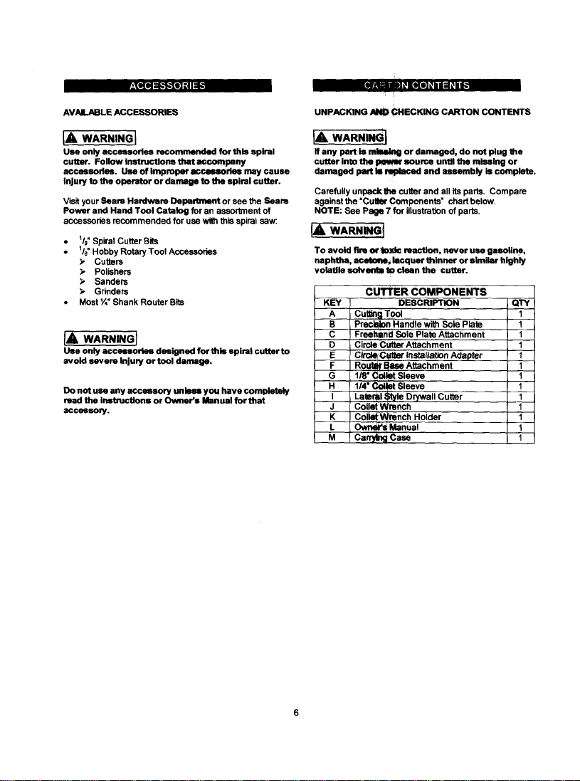
AVAILABLE ACCESSORIES
I r II _J_mn1_i_
UNPACKING _ CHECKING CARTON CONTENTS
!i !
[A WARNING I
Use only accessories recommended for this spiral
cutter. Follow instructions that accompany
accessories. Use of improper accessories may cause
Injury to the operator or damage to the spiral cutter.
Visit your Sears Hardware Department or see the Seam
Power and Hand Tool Catalog for an assorbllent of
accessories recommended for use with this spiral saw:
• _/e" Spiral Cutter Bits
• 1/8"Hobby Rotary Tool Accessories
;, Cutters
_, Polishers
Sanders
;, Grinders
• Most ¼" Shank Router Bits
IA wAe.,.o]
Use only accessories designed for this spiral cutter to
avoid severe Injury or tool damage.
Do not use any accessory unless you have completely
read the Instructions or Owner's Manual for that
accessory.
IA WARNmGI
If any part is mlsek!tg or damaged, do not plug the
cutter into the PoWer source until the missing or
damaged part Is replaced and assembly is complete.
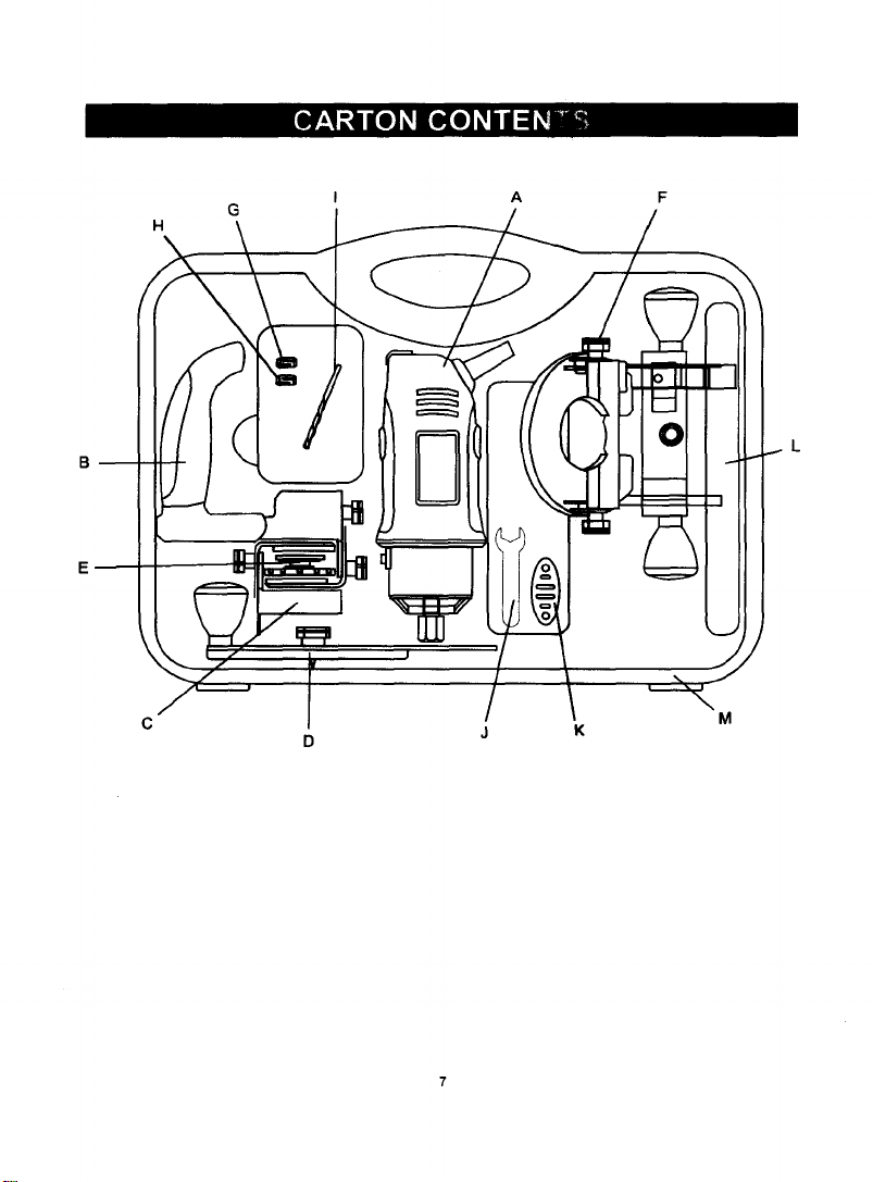
Carefully unpackthe cutter and all its parts. Compare
against the =Cutm" Components" chart below.
NOTE: See Page 7 for illustm'don of parts.
IA, WARNING I
To avoid fire or, toxic reaction, never use gasolin e,
naphtha, acetolm_ lacquer thinner or similar highly
volatile solvents to clean the cutter.
CUTTER COMPONENTS
KEY DESCRIPTION QTY
A CuWn_ Tool 1
_C B-- Precil_k:)n Handlewith Sole Plata 1
Freehand Sole Plate Attachment 1
D Circle Cutter Attachment 1
c_€_ Instaita=nAdepter 1
R0U _t_TBase Attachment 1
G 118" Col_t Sleeve t
1/4" Co41_t Sleeve 1
Lateral Style Drywall Cutter 1
J Collet Wrench I
K Coll_Wrench Holder 1
Owr_, _! Manual 1
Canyll_ Case 1
[_ [o,Io_
C
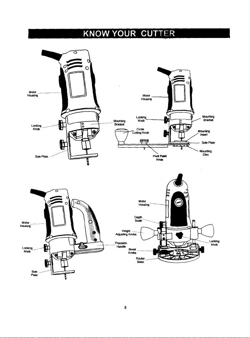
K41_e]vAvJk_e]l_ [e,]l]lil_l
Loddng
Knob
Motor .... _
Housing
Sole _/
Plate
Sole Plate _F_
|
Mou_ting L / MBr°Ua_
Circle
CutBng Knob Mir_g
Sole Plate
Y'_ J _'-_'"_ Mounting
Pi_ _ Disc
Adjusting Knobs
P_dsior_
Handle
eev_
KnObs
Router
Base
Locking
KnOb
IA WARNINGI
Remove the plug from the power source before
assembly, changing accessorkm or cutters and
making adjustments. This safety action wftl help
prevent accidental etarting of the tool which could
result In eertous Injury.
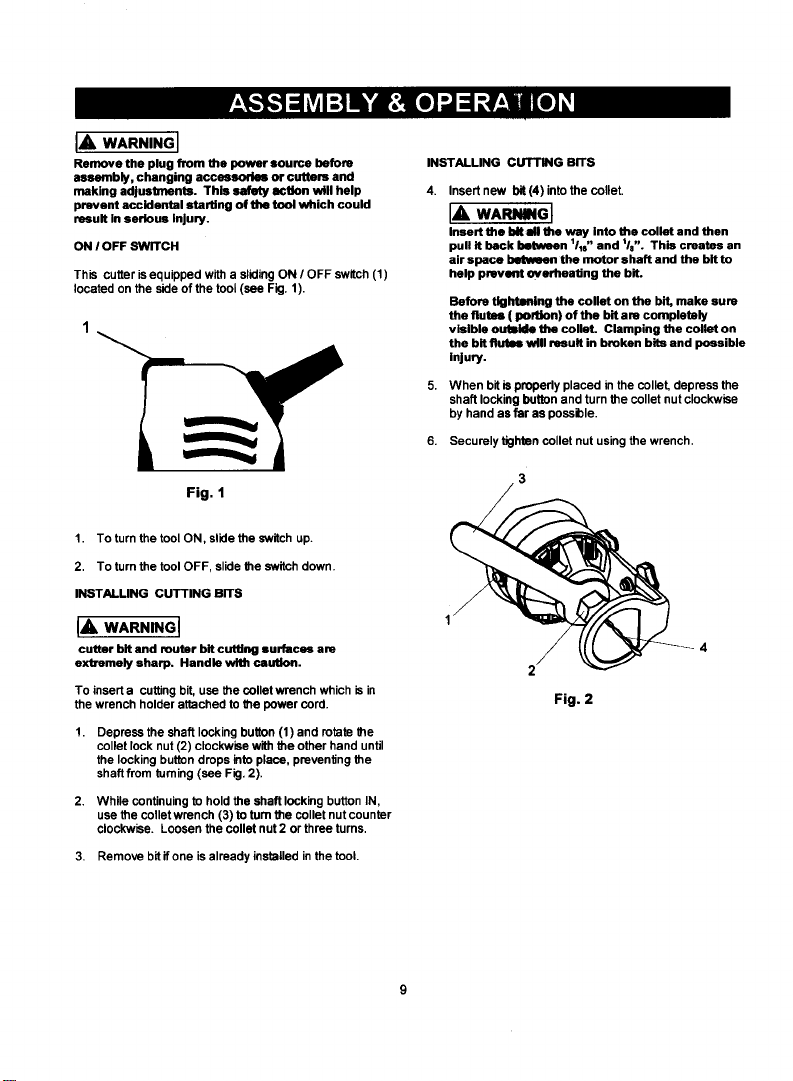
ON I OFF SWITCH
This cutter is equipped with a sliding ON / OFF switch (1)
located on the side of the tool (see Fig. 1 ).
Fig. 1
1. To turn the tool ON, slide the switch up.
2. To turn the tool OFF, slide the switch down.
INSTALLING CUTTING BITS
IA WARNING]
cutter bit and router bit cutting surfaces am
extremely sharp. Handle with caution.
To insert a cutting bit, use the collet wrench which is in
the wrench holder attached to the power cord.
Depress the shaft locking button (1) and rotate the
collet lock nut (2) clockwise with the other hand until
the locking button drops into place, preventing the
shaft from turning (see Fig. 2).
2. While continuing to hold the shaft locking button IN,
use the collet wrench (3) to turn the collet nut counter
clockwise. Loosen the collet nut 2 or three turns.
3. Remove bit ifone is already installed in the tool.
INSTALLING CUTTING BITS
4. Insert new bit (4) into the colleL
I_ WARNING I
Insert the bit all the way Into the collet and then
pull it back between 111s"and tla". This creates an
airspace between the motor shaft and the bltto
help prevent overheating the bit.
Before tight=ruing the collet on the bit, make sure
the flutes (poItion) of the bit are completely
visible outside the colleL Clamping the collet on
the bit flutsl w#l result in broken bits and possible
injury.
5. When bit ispropedy placed in the collet, depress the
shaft locking button and turn the collet nut clockwise
by hand as far as possible.
6. Securely tighten collet nut using the wrench.
Fig. 2
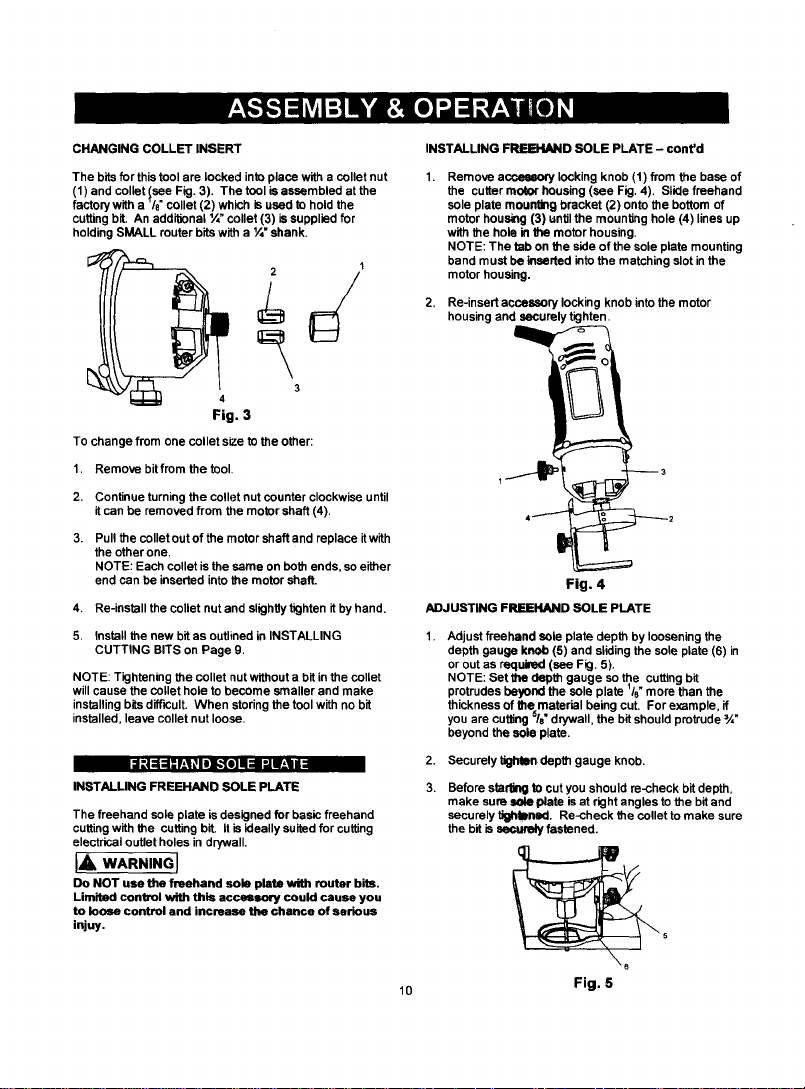
CHANGING COLLET INSERT
The bits for this tool are locked into place with a collet nut
(1) and collet lsee Fig. 3). The tool is assembled at the
factory with a "/8"collet (2) which is used to hold the
cutting bit. An addil_onal ¼" collet (3) issupplied for
holding SMALL router bits with a I/4" shank.
Fig. 3
To change from one collet size to the other:
1. Remove bit from the tool.
2. Continue turning the collet nut counter clockwise until
it can be removed from the motor shaft (4).
3. Pull the collet out of the motor shaft and replace it with
the other one.
NOTE: Each collet is the same on both ends, so either
end can be inserted into the motor shaft.
4. Re-install the collet nut and slighity tighten it by hand.
5. Install the new bit as outlined in INSTALLING
CUTTING BITS on Page 9.
NOTE: Tightening the collet nut without a bit in the collet
will cause the collet hole to become smaller and make
installing bits difficult. When storing the tool with no bit
installed, leave collet nut loose.
l:|=Izl==f±_l_li_ fo]II=l I'nI_II
INSTALLING FREEHAND SOLE PLATE
The freehand sole plate is designed for basic freehand
cutting with the cutting bit. It is ideally suited for cutting
electrical outlet holes in drywall.
IA WARNiNGJ
Do NOT use the freehand sole plate with router bits,
Limited control with this accessory could cause you
to loose control and increase the chance of serious
injuy.
INSTALLING FREEHAND SOLE PLATE - cont'd
Remove a_ locking knob (1) from the base of
the cutter motor housing (see Fig. 4). Slide freehand
sole plate mounting bracket (2) onto the bottom of
motor housing (3) until the mounl_ng hole (4) lines up
with the hole in the motor housing.
NOTE: The tab on the side of the sole plate mounting
band must be inserted into the matching slot inthe
motor housing.
2. Re-insert accessorylocking knobintothe motor
housingand securelytighten.
Fig. 4
ADJUSTING FREEItAND SOLE PLATE
Adjust freehand sole plate depth by loosening the
depth gauge knob (5) and sliding the sole plate (6) in
or out as required (see Fig. 5).
NOTE: Bet the depth gauge so the cutting bit
protrudes beyond the sole plate '/8" more than the
thickness of the material being cut. For example, if
you are cutting 5/8" drywall, the bif should protrude ¾"
beyond the sole plate.
2. Securely tighfan depth gauge knob.
Before starting to cut you should re-check bitdepth,
make sure sole plate is at right angles to the bit and
securely t_ned. Re-check the collet to make sure
the bit is sec_ fastened.
10
Fig. 5
IAWARN,NOr
Have you read "POWER TOOL 8AI=ETY",
"CUTTER SAFETY" and "ELECTRICAL SAFETY"
on pages 3, 4 and 5 of thto Manual? If not, please
do It now before you operate thto cutter. Your
safety depends on ttl
Every time you use the cutmr you should verify
the following:
1. cutmr cord Is not damaged.
2. BIt is correct type for the matarlal being cut.
3. Bit to sharp, In 9God cond#lon, properly
installed and securely tighlMitted.
4. Safety glasses and dust mask are being wom.
Failure to adhere to these safety rules can greatly
increase your chances of Injury.
PRACTICE CUTS USING FREEHAND SOLE PLATE
Before attempting to work on an actual project, take the
time to make a few practice cuts with your saw. Use
some scraps of material that are the same materisl as
used in your actual project.
1. Draw a pattom similar to your f'wstproject on a scrap
piece of material.
2. Install freehand sole plato as shown in Fig. 4.
3. Install cutting bit in the collet as shown in Fig. 2.
4. Adjust depth of freehand sole plate as shown in Fig. 5.
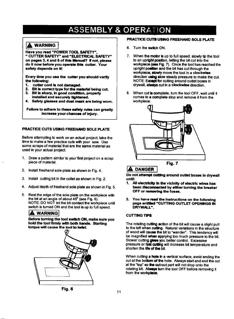
Rest the edge of the sole plate on the workpiece with
the bit at an angle of about 45 ° (see Fig. 6).
NOTE: DO NOT let the bit contact the workpiece until
switch is tumed ON and the tool is up to full speed.
IA WARNINGI
Before turning the tool switch ON, make sure you
hold the tool flnnty with both hands. Starting
torque will cause the tool to twtot.
PRACTICE GUTS USING FREEHAND SOLE PLATE
6. Turn the switch ON.
7.
When the motor is up to full speed, slowly tip the tool
to an upright position, letting the hit cut into the
workpiece (lee Fig. 7). Once the tool has reached the
upright pceil_n and the bit has cut through the
workpiac.e, slowly move the tool in a clockwk_
diraction ulll_ slow steady pressure to make the cut,
NOTE: E._e_ for cutting around outlet bo_es in
drywall, always out in a clockwise direction.
When cut is cumpleto, turn the tool OFF, wait until it
comes to a complete stop and remove it from the
workpiece.
Fig. 7
IA DANGER I
Do not attempt ©uttlng around outlet boxes in dwwall
until:
1. All electricity lit the vicinity of electric wires has
been disr.olmectad by either turning the breaker
OFF or remmtlng the fuses.
2. You have mind the instructlous on the following
page entitled =CU'I-FING OUTLET OPENINGS IN
DRYWALL".
CUTTING TIPS
The rotating cuffing aclJon of the bit will cause a slight pull
to the left when cut_g. Natural vedatJons in the structure
of wood will cause the bit to "wander'. This tendency will
be magnified when applying too much pressure to the bit.
Slower cutting _ you better control. Excessive
pressure or fa_ _ will increase bit temperature and
shorten the life oflhe bit.
When cutting a hole b a vertical surface, avoid ending the
cut at the betll_it el' the hole. Always start and end the cut
at the "top" so ate cut.out part will not drop onto the
rotating bit. Alway= turn the tool OFF before removing it
from the workpleoe.
Fig. 6 I_
[,:][oT
CUTTING OUTLET OPENINGS IN DRYWALL CUTTING OUTLET OPENINGS IN DRYWALL - cont'd
IA DANGER I 6.
Do not attempt to use this tool to make cut-outa
around any fixture or opening which has live electdcal 7.
wires or on any wall which may have elect]rlcal wiring
behind it. If a live wire is contacted, the bit could
conduct the electric current to the tool, cresting an
electrocution hazard forths operator. Tum OFF 8.
breakers or remove fuses to disconnect the electric
circuit in the area of work. Aliways hold the tool by its
insulated housing when working In areas where there
is a possibility of contacting electric wires. Always
wear eye protection when operating this tool.
Before installing drywalH, push the electrical wires to
the back of the box as far as possible so they will not
be cut by the bit when cutting the opening.
Before fastening the drywall sheet over the electrical
box, mark the sheet as close as possible to the center
of the box opening. Mark should be on the side of the
drywall facing you.
3. When fastening the drywall in place, do not place nails
or screws closer than _2" from the box. This will
prevent the drywall from becoming deformed under
pressure.
Insert cutter and install freehand sole plate as
outlined on Pages 9 & 10 of this Owner's Manual.
Adjust dept of cut so the bit will protrude _/e" beyond
the thickness of the drywall.
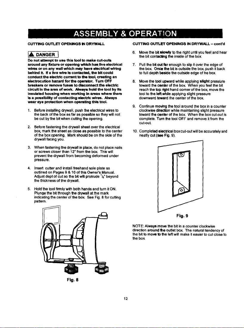
Hold the tool firmly with both hands and turn it ON.
Plunge the bit through the dq/wall at the mark
indicating the center oF the box. See Fig. 8 for cutting
pattern.
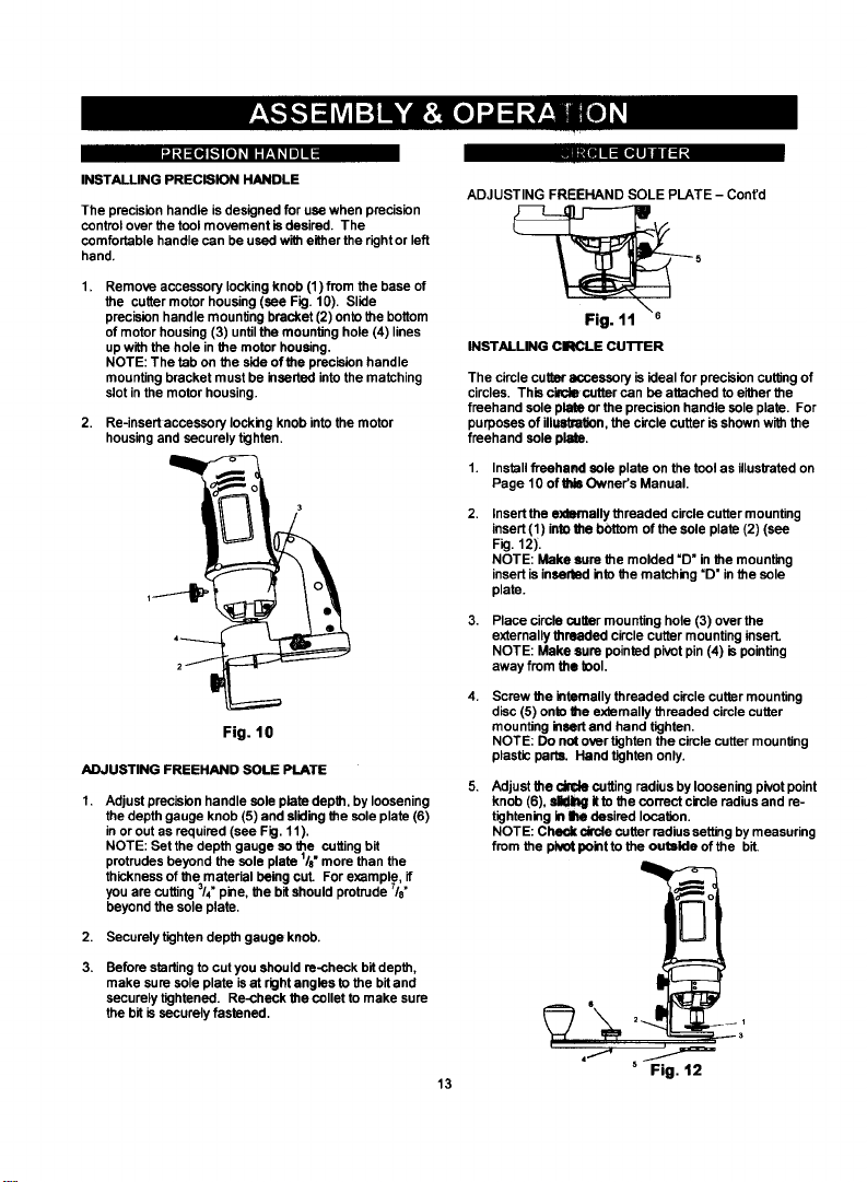
Move the bit slowly to the right until you feel and hear
the bit contacting the inside of the bo_
Pull the bit out far enough to slip it over the edge of
the bo_ Onoe the bit isoutside the box, push it back
to full depth beside the outside edge of he box.
Move the tool upward while applying slight pressbre
toward the cenler of the bo_ When you feel the bit
reach the top right hand comer of the box, move the
tool to the left while applying slight pressure
downward toward the center of the bo:_
Continue moving the tool around the box in a counter
clockwise direc_n while maintaining slight pressure
toward the center of the box. When the box cut-out is
complete, Turn the tool OFF and remove it from the
cut-out.
10. Completed elec_ical box cut-out will be accurately and
neatly cut (see Fig. 9).
Fig. 8
Fig. 9
NOTE: Always move the bit in a counter clockwise
directten around the outlet box. The natural tendency of
the bitto move tothe left will make it easier to cut close to
the bo_
12
I-) lS"d5:][o)"-.] iOD]
•J_(_k,"l[e] _1I_"f__l_l|]ll III In= [qgiianil=l"
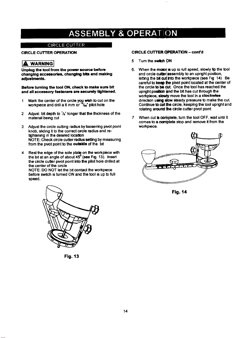
INSTALLING PRECISION HANDLE
The precision handle is designed for use when precision
control over the tool movement is desired. The
comfortable handle can be used with either the right or left
hand.
Remove accessory locking knob (1) from the base of
the cutter motor housing (see Fig. 10). Slide
precision handle mounting bracket (2) onto the bottom
of motor housing (3) until the mounting hole (4) lines
up with the hole in the motor housing.
NOTE: The tab on the side of the precision handle
mounting bracket must be inserted into the matching
slot in the motor housing.
2. Re-insert accessory locking knob into the motor
housing and securely tighten.
Fig. 10
ADJUSTING FREEHAND SOLE PLATE
Adjust precision handle sole plate depth, by loosening
the depth gauge knob (5) and sliding the sole plate (6)
in or out as required (see Fig. 11).
NOTE: Set the depth gauge so the cutting bit
protrudes beyond the sole plate Is" more than the
thickness of the material being cut. For example, if
you are cutting /4" pine, the bit should protrude Is"
beyond the sole plate.
2. Securely tighten depth gauge knob.
Before starting tocut you should re-check bitdepth,
make sure sole plate is at right angles to the bit and
securely tightened. Re-check the collet to make sure
the bit is securely fastened.
3 7
1
ADJUSTING FREEHAND SOLE PLATE - Cont'd
INSTALLING CIRCLE cU'rFER
The circle cutter accessory is ideal for precision cutttng of
circles. This cbcle cutter can be attached to either the
freehand sole plate or the precision handle sole plate. For
purposes of illustralten, the circle cutter is shown with the
freehand sole plate.
1. installfieeharKI sole plate on the toolas illustratedon
Page 10 of_ Owner's Manual.
insert the externally threaded circle cutter mounting
insert (1) into Ute bottom of the sole plate (2) (see
Fig, 12),
NOTE: Make sure the molded "D" in the mounting
insert is inserted into the matching "D" in the sole
plate.
Place circle cutter mounting hole (3) over the
externally threaded circle cutter mounting insert.
NOTE: Make sure pointed pivot pin (4) is pointing
away from the tool.
Screw the internally threaded circle cutter mounting
disc (5) onto the externally threaded circle cutter
mounting insert and hand tighten.
NOTE: Do not over tighten the cimle cutter mounting
plastic parts, Hand tighten only.
Adjust the dr{de cutting radius by loosening pivot point
knob (6), _ It to the correct circle radius and re-
tightening In Ire desired location.
NOTE: C_ drcte cutter radius setting by measuring
from the pivot point to the outside of the bit,
13
Fig. 12
I]I _MII mR[_-_--- --
CIRCLE CUTTER OPERATION
IA WARNINGI
Unplug the tool from the power source before
changing accessories, changing bits and making
adjustments.
Before turning the tool ON, check to make sum bit
and all accessory fasteners are securely tightened.
1 Mark the center of the circle you wish to cut on the
workplace and dnll a 6 mm or s/, pilot hole
2 Adjust bit depth to l/o" longer that the thlckness of the
material being cut
Adjust the ctmle cuitmg radius by loosening pivot pomt
knob, sl_tng itto the correct c_rcle radius and re-
tightemng tn the desired Iocafion
NOTE: Check circle cutter radius setting by measunng
from the pNot point to the outside of the bit
Rest the edge of the sole plato on the workplace with
the bd at an angle of about 450 (see F_j. 13). Insert
the circle cutter p_votpotnt into the pilot hole drilled at
the center of the circle
NOTE: DO NOT let the bit contact the workptece
before switch tsturned ON and the tool is up to full
speed.
CIRCLE CUTTER QPERATION - cont'd
5 Tumthe_0N
6. When the molo_ m up m full speed, slowly tip the tool
and circle cuter assembly to an uprK3ht position,
letting the bitcu_lnto the workpiace (see FK3 14) Be
careful to keep the pivot point located at the center of
the ctrcle to N Cut. Once the tool has reached the
upnght posl_n and the bit has cut through the
workpiece, ak_ move the tool in a clockwise
dtrecbon ulblg slow steady pressure to make the cut.
Continue tO c,_ _ circle, keeping the tool upnght and
rotating around the circle cutter pivot potnt
7 When cut is con_ptete, tom the tool OFF, wa_ unttl it
comes to a ocmplete stop and remove it from the
workpN_3e.
Fig. 14
Fig. 13
14
;|O|IPlll = =4I-'f_-_-_
The router accessory converts your cuffing tool into a
small hobby router that is capable of handling small 1/4,
shank router bits as well as the cuffing bit. The tilting
base isideal for bevel cutting.
IA WARNiNGI
Unplug the tool from the powor source before
changing accessories, changing bits and making
adjustments.
Before tuming the tool ON, check to make sure _e bit
and all accessory fastonere ere securely tightened.
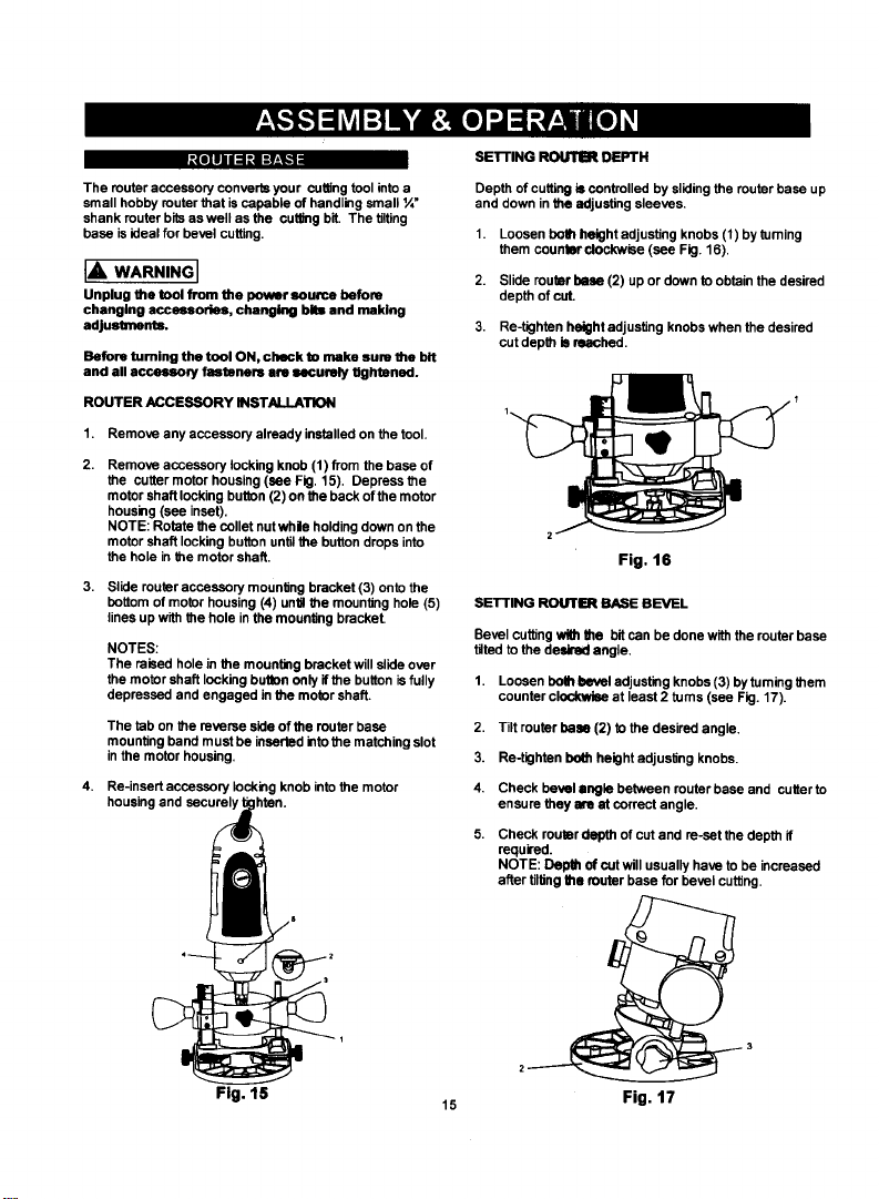
ROUTER ACCESSORY INSTALLATION
1. Remove any accessory already installed on the tool.
Remove accessory locking knob (1) from the base of
the cutter motor housing (see Fig. 15). Depress the
motor shaft locking button (2) on the back of the motor
housing (see inset).
NOTE: Rotate the collet nut whle holding down on the
motor shaft locking button until the button drops into
the hole in the motor shaft.
3. Slide router accessory mounitng bracket (3) onto the
bottom of motor housing (4) unUl the mounting hole (5)
lines up with the hole in the mounting bracket.
NOTES:
The raised hole in the mounting bracket will slide over
the motor shaft locking button only if the button is fully
depressed and engaged in the motor shaft.
The tab on the reverse side of the router base
mounting band must be inserted into the matching slot
in the motor housing.
4. Re-insert accessory locking knob into the motor
housing and securely I hten.
SETFING ROUTIER DEPTH
Depth of cutting is controlled by sliding the router base up
and down in the adjusting sleeves.
1. Loosen both height adjusting knobs (1) by turning
them countm'clockwise (see Fig. 16).
2. Slide router bose (2) up or down to obtain the desired
depth of cut.
3. Re-tighten height adjusUng knobs when the desired
cut depth is reached.
Fig. 16
SETTING ROUTER BASE BEVEL
Bevel cuffing with the bit can be done with the router base
ti/ted to the deldred angle.
1. Loosen both bevel adjusting knobs (3) by tuming them
counter clockwise at least 2 turns (see Fig. 17).
2,
Tilt router base (2) to the desired angle,
3.
Re-tighten both height adjusitng knobs.
4,
Check bevel angle between router base and cutter to
ensure they are at correct angle.
Check router depth of cut and to-set the depth if
required.
NOTE: Depth of cut will usually have to be increased
after tilting the router base for bevel cuffing.
Fig. 15
15
Fig. 17
 Loading...